

Page 1

TRITTONTRITTON
www.dimmer.de
COMPACT CONTROL FOR
THEATRE AND LIVE
24 CH / 36 CH / 48 CH
USER MANUAL
Version 1.3
Page 2

Page 3

User Manual - Index
LT- A
INDEX
1 - PRESENTATION 1
INTRODUCTION 1
2 - TECHNICALS CHARACTERISTICS 3
TECHNICALS CHARACTERISTICS - DEFINITION 3
CONECTIONS 5
DMX-OUT 5
MIDI IN-THRU-OUT 5
MAINS 5
INSTALLATION 6
MAINTENANCE 6
TECHNICAL SERVICE 6
3 - LAYOUT & BASIC FUNTIONS 7
LAYOUT: LOGIC PARTS 7
MANUAL FIELD 7
MASTERS 7
GENERAL CONTROL 7
SEQUENCE 8
GENERAL MASTER & BLACKOUT KEY 8
MAIN SYSTEM INSTALLATION. COLD RESET 9
THE MANUAL FIELD: C1..C24 FADERS 9
CHANNELS GROUPS 10
MEMORIES OR PRESETS 11
LOADING PRESET IN THE MASTERS 12
RECORDING MASTER PAGES 14
MAIN MENU 16
EDITOR FOR THE MANUAL FIELD: zz NUM zz 17
PRESETS & GROUPS MODIFICATION 19
4 - MASTERS 23
FUNCTIONS KEYS ASSOCIATED TO THE MASTERS 23
WORKING IN "GO" MODE 23
MASTER FLASH FUNCTION 24
NOTES ABOUT THE MASTERS 24
5 - THE SEQUENCE 27
Page 4

Manual de Usuario - Index
B - LT
THE SEQUENCE 27
WORKING WITH THE SEQUENCE 27
EDITING THE SEQUENCE 29
NOTES ABOUT THE SEQUENCE: 31
NOTES FOR SETUP AND SEQUENCE 31
ERASING THE SEQUENCE: DEL 32
6 - THE CHASES 35
THE CHASES 35
STORING A CHASE 35
NOTES ABOUT THE CHASE EDITION: 37
THE CHASES IN THE MASTERS 38
7 - SETUP 41
SYSTEMS SETUP 41
PCH - 24/36/48 CONTROL CHANNELS: 512 DIMMER CHANNELS 41
EDIT, EDITS THE CHANNEL PATCH 42
EDITING THE PATCH 43
SEQ- PARAMETERS FOR THE SEQUENCE 44
SOLOON/SOLOOFF 45
TºON/TºOFF 45
RECFIXED / RECFREE 45
GM - GENERAL MASTER PARAMETERS 46
CH 46
BLKOUTENABLED / BLKOUTDISABLED 46
PRH- PREHEAT FUNCTION 47
LV (LEVEL) 47
CAP (CAPTURE) 47
MEM - THE SHOW DATA. 48
EX (EXAM) 48
LO (LOAD) 48
REC 48
DEL (DELETE) 49
FORMT (FORMAT) 49
SYSTEM EXCLUSIVE: SYSX RXD TXD 49
MID - MIDI PORT CONFIGURATION 50
ON/OFF 51
IN/OUT 51
CH1 51
INFO 51
-> - TO ACCESS TO THE SECOND SETUP DISPLAY 53
RST - WARM RESET 54
LNG - LANGUAGE 54
CT - DISPLAY CONTRAST 54
BEEP - ACOUSTIC SIGNAL 55
XF - CROSSFADE TYPE 55
Page 5

Manual de Usuario - Index
LT- C
SCR - SCROLLERS (COLOUR CHANGERS) 56
8 - TEST 59
SOFTWARE TEST 59
BUF (BUFFER) 59
HARD (HARDWARE) 59
MEM (MEMORY) 59
VER (VERSION) 60
HARD (HARDWARE TEST) 60
INPUT 60
MEM (MEMORY) 60
DISP (DISPLAY) 60
BEEP 61
LEDS 61
9 - WORKING WITH SCROLLERS 63
DEFINING ONE CONTROL CHANNEL LIKE SCROLLER 63
SCROLLERS EXAM 63
WORKING WITH THE SCROLLERS 63
10 - WORKING WITH MIDI 65
MIDI PORT CONFIGURATION 66
FOR MORE INFORMATION... 66
11 - EXAM FUNCTION 67
12 - SPECIAL FUNCTIONS - TIME 69
‘CAPTURING’ DELAY TIMES FOR THE SEQUENCE 69
‘CAPTURING’ STEP TIMES FOR THE CHASE 70
Page 6

Manual de Usuario - Index
D - LT
Page 7

User Manual - Lesson 1 - Presentation
LT & 1
1 - PRESENTATION
INTRODUCTION
There are three models for the manual control console "TRITTON":
• TRITTON-24, for 24 control channels / 12 masters.
• TRITTON-36, for 36 control channels / 24 masters.
• TRITTON-48, for 48 control channels / 36 masters.
These control boards are manufactured completely with digital technology, and passed the hard
control tests.
The manipulation of these consoles is very easy, quick and efficient, in this way the user can use the
100% of the console tools. TRITTON is a console cheaper and very functional.
TRITTON has a great number of possibilities similar to sophisticated consoles possibilities, in
constant update.
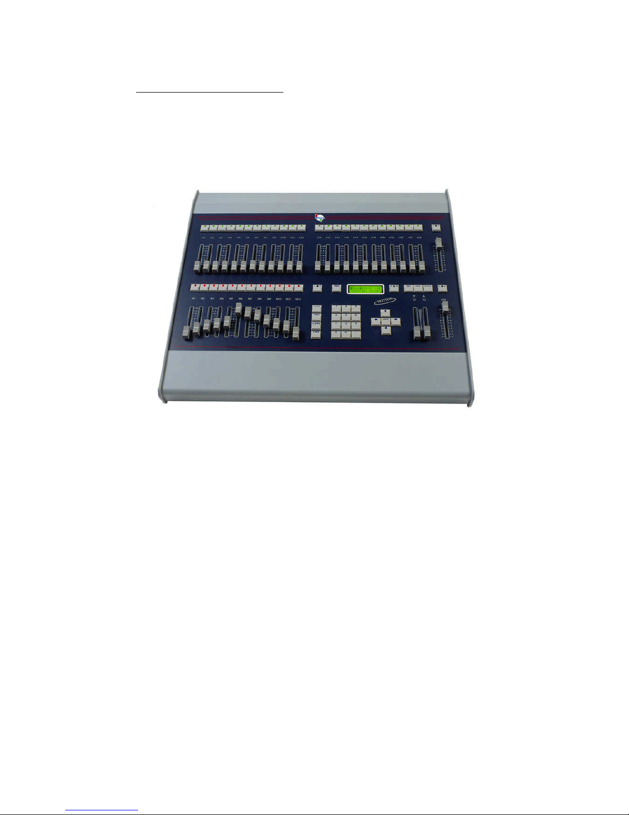
There are 3 different models, one model for each requirement. In the next figure, we can see the
basic parts:
• Manual field. (24 faders for TRITTON-24, 36 for TRITTON-36 and 48 for TRITTON-48).
• Masters. (12 masters for TRITTON-24, 24 for TRITTON-36 and 36 for TRITTON-48).
• Sequence.
• General Master.
• General control, with a display, numeric keyboard, cursors and dedicated function keys.
The difference between models is the channels and masters number.
Page 8
User Manual - Lesson 1 - Presentation
2 & LT
TRITTON-24:
Page 9

User Manual - Lesson 2 - Technical Characteristics
LT & 3
2 - TECHNICALS CHARACTERISTICS
TECHNICALS CHARACTERISTICS - DEFINITION
• Control channels: 24, 36 or 48.
• Masters: 12, 24 or 36. Masters for channels groups, presets or chases.
• Dimmers channels: 512.
• Presets or memories: 800 (1 -799).
• Channel Flash.
• Masters Flash, in modes Solo and Normal.
• Times in masters.
• 99 Chases of steps no limited, with presets, groups or channels: With level and rate control, 3
directions, and 5 reproduction modes (4 hard modes and 1 soft mode).
• Sequence: 1000 steps. All step with a preset, time-in, time-out, delay and jump.
• Dipless crossfade.
• 99 master pages.
• 14, 26 or 38 simultaneous fades, for TRITTON-24, 36 or 48 respectively.
• EXAM function. Helps us to know any recorded information.
• MODIFY function. Permits us to modify presets and groups.
• Setup.
• Patch: 512 dimmers, 4 curves and maximum output level by channel.
• Preheat function.
• MIDI port configuration.
• Inner data memory, for data shows. Functions: record, load, exam... and permits us to
export the data show to a MIDI sequencer (Sysex).
• Warm reset.
• Messages language selection.
• Scrollers patch.
• ... And other friendly functions of the LT consoles.
Page 10

User Manual - Lesson 2 - Technical Characteristics
4 & LT
• Hardware and software tests.
• Output buffer.
• Tests for keys, potentiometers, LED's, display, inner data memory...
• Free memory test…
• General Master. (It is possible to exclude channels of this control).
• Black-Out key. (It is possible enable or disable this function key).
• Scrollers, (colour changer), management.
• MIDI IN-THRU-OUT.
• DMX-512 1990 (USITT).
• Alphanumeric display - 2 x 16 characters.
• Digital technology:
• Microprocessor: H8/3003 - 16 Mhz.
• EPROM: 512 Kb.
• RAM. 512 Kb.
• Size:
• TRITTON-24: 540 mm. x 500 mm. x 60 mm...160 mm. 6 Kg.
• TRITTON-36: 770 mm. x 500 mm. x 60 mm…160 mm. 8 Kg.
• TRITTON-48: 1000 mm. x 500 mm. x 60 mm…160 mm. 10 Kg.
• 85-265V~ / 50-60 Hz.
• Nominal Power: 21W.
• Nominal Intensity: 0.165 A.
• Protection: 2 fuses x 1 A/250V type F
• Temperature: -45º / 80ºC
• Humidity: 80% (no condensation).
• CAT II.
Page 11
User Manual - Lesson 2 - Technical Characteristics
LT & 5
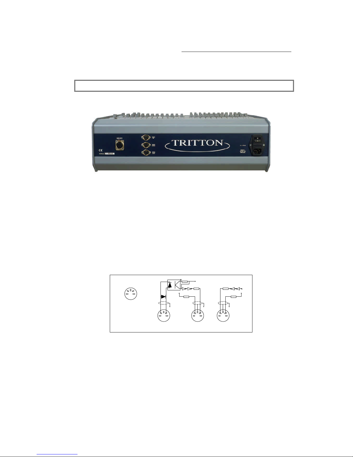
CONECTIONS
In the rear panel:
DMX-OUT
DMX-512 (1990) output, according to the USITT. (Standard female XLR-5). Code:
Pin 1: GND.
Pin 2: Data -.
Pin 3: Data +.
3 & 4 pins: No connected.
MIDI IN-THRU-OUT
Standard port MIDI: 3 female DIN-5 (180º):
1
4
2
5
3
DIN-5180º
R
R
R
R
R
MIDI-OUTMIDI-THRUMIDI-IN
MAINS
Mains input: 85-265V∼ / 50-60Hz. IEC base with 2 fuses enclosure (1 A / 250V type F fuses), and
on/off switch (I position on & O position off).
Notes:
In the inner power supply, there is one 2 A fuse. Remember this for your replacements!
You have to use cables with earth connection (normalised cables).
Page 12

User Manual - Lesson 2 - Technical Characteristics
6 & LT
INSTALLATION
TRITTON is distributed ready to work:
• Unpack the console with care.
• Place the console in a plane surface.
• Connect the power cable to the IEC base, in the rear of TRITTON. Always use power cable
with earth, normalised.
• Connect the DMX output cable to the connector marked like DMX OUT, Always use data
cable for the RS485 standard: twisted pares screened, of low capacitance and 120 ohms
impedance.
• Switch on the console. Switch in position I.
TRITTON is ready to work!
MAINTENANCE
TRITTON doesn't need periodical maintenance.
Cleaning: Clean the external surfaces with a cloth wetted in water.
TECHNICAL SERVICE
GERMANY: Geo-Technic
Fax: 0049 (0) 6188 - 90 11 41
Tel: 0049 (0) 6188 - 90 11 40
Actualization of software: www.dimmer.de
Page 13

User Manual - Lesson 3 - Layout & Basic
LT & 7
3 - LAYOUT & BASIC FUNTIONS
LAYOUT: LOGIC PARTS
In the frontal panel of the console we can find:
MANUAL FIELD
The 24 potentiometers (36 for TRITTON-36 or 48 for TRITTON-48), localizer in the upper zone,
and marked like C1..C24 are the channels level potentiometers. All potentiometer has one Flash
key associated.
All Flash keys have a green LED. In this LED we can see the output level of its associated channel.
These keys are affected only by the general master position.
In the frontal panel, (upper left), we can find the C potentiometer, this potentiometer controls the
manual field output in scene, (C potentiometer doesn't affect the channel flash level), is the manual
field master.
Over this potentiometer we can find the SG.DB key. This key permits us to choose between two
manual field modes: Single (LED off) y Double (LED on).
MASTERS
There are 12 masters (24 for TRITTON-36 & 36 for TRITTON-48), marked like M1..M12. All
masters have associated a multifunction key.
The multifunction key, Mn, (M1..M12), can work like:
• Master assignation key. It used for load or remove groups, memories or chases in a master.
• Master Flash key: Modes normal and solo.
• GO key: Start fades of the master assignation, (group or memory) or Start the chase (automatic
or step by step modes).
These keys have a red LED, this LED show us the associated master status.
GENERAL CONTROL
Located near the masters and under manual field, we can find this general control section. The
general control is composed by:
• 2x16 characters alphanumeric display, monitoring the menus, numerical data, fault and
information messages, and any other needed information...
• Numerical keyboard.
• Arrows & ENTER keys.
Page 14

User Manual - Lesson 3 - Layout & Basic Functions
8 & LT
• And the dedicated keys:
• FL-MT chooses the working mode of the associated keys to the masters, Mn, like GO,
normal master flash or solo master flash keys.
• LOAD loads groups, memories, chases or pages in the masters.
• TIME loads times in the masters are assigned with presets (memories) or groups, and
for others special functions.
• EX-AM accedes at the information recorded in the console. (This key works in
conjunction with the rest of the console keys).
• REC records presets, chases and pages.
• DELETE deletes presets, pages, manual field, chases and other cleared functions in
masters and menus.
• INSERT, works in the menus: sequence, chase and patch editing menus. And in
playback mode, this key jumps to the desired position in the sequence.
SEQUENCE
With two potentiometers, X1 & X2, for manual control, and the next functions keys:
GO: Starts the present crossfade.
GO-BACK: Starts the crossfade in invert direction, crossfading at the previous step in the
sequence.
PAUSE: Stops the started crossfade.
In playback mode, INSERT key jumps at the desired position in the crossfade steps.
GENERAL MASTER & BLACKOUT KEY
The general master is the potentiometer located on the frontal panel (right down).
The general master is associated with the Black-Out key, BLK-OUT, above the GM fader.
Page 15
User Manual - Lesson 3 - Layout & Basic Functions
LT & 9
MAIN SYSTEM INSTALLATION. COLD RESET
1.- Connect the output cable. 5 pin XLR DMX.
2.- Connect the IEC mains lead.
3.- Press and hold down ßß key (for "cold reset") and switch on the console power, release the key.
The first time that we start the console have to do "cold reset", and each time that we want erase all
recorded data in the console. For the cold reset: Press and hold down ßß key, and switch on the
console power.
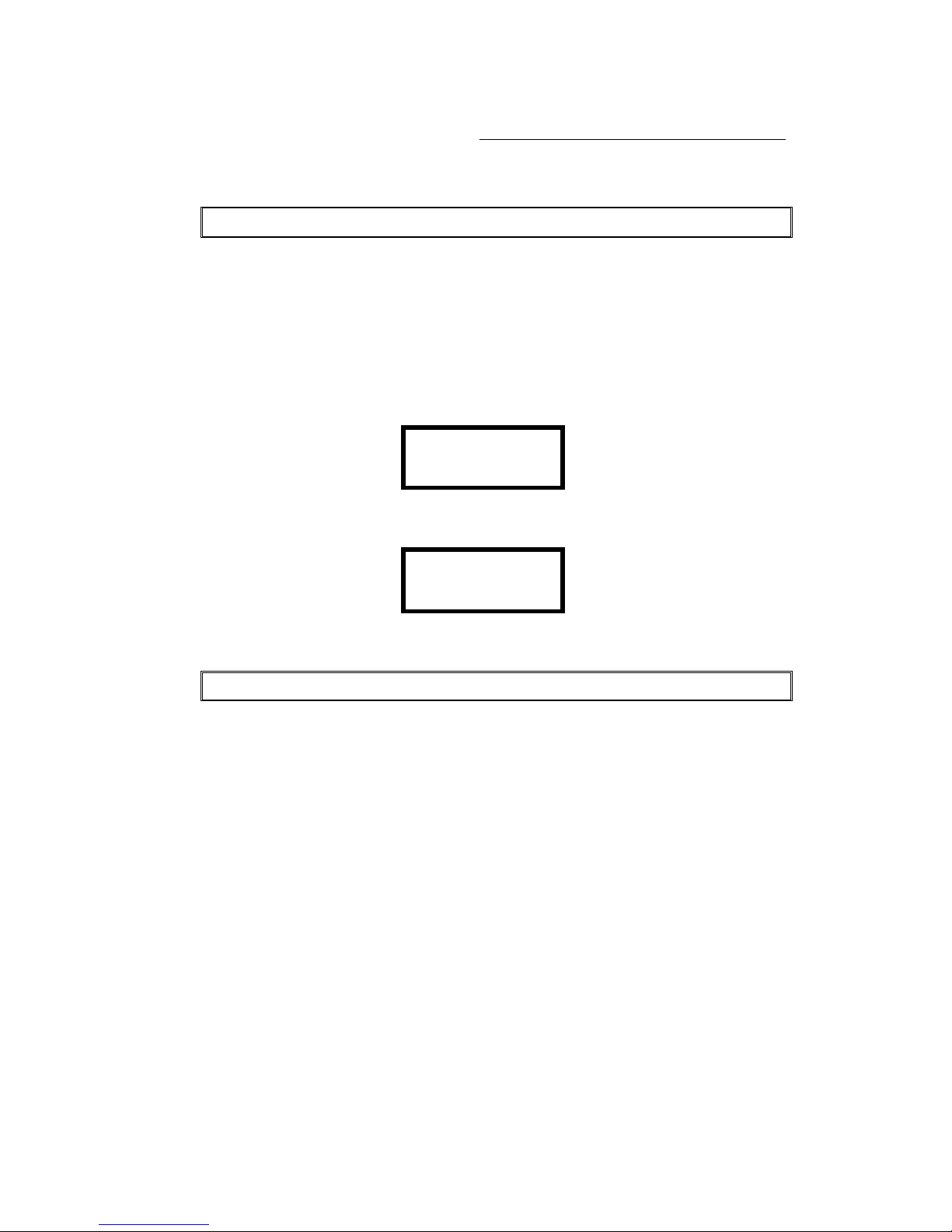
After the "cold reset", in the console display we can read (for a short time):
LT COPYRIGHT
TRITTON 24 V1.30
And after, we can see the main menu:
nMainnSEQ >0
MDFY NUM ->
THE MANUAL FIELD: C1..C24 FADERS
• Locate the general master, GM, at 100%.
• Confirm that the BLK.OUT & SG.DB keys are not activated (LED off).
From the manual field we have control about 24 console channels:
With the C master (manual field general master) at 100%: When a fader is moved out the its 0%
level, its corresponding control channel outs in scene, with a proportional level to the marked level
with the potentiometer. The associated flash key LED shows us this level.
When we push the channel flash key, and while this is pushed, the channel is at 100% level.
The manual field output is proportional to the C master level. When the C master is in its 0% (the
down end of its travel), there is not manual field output.
Note: The Flash keys are not controlled for the C master.
How to remove the output to scene of the manual field? There are three possibilities:
1. Move the 24 manual field faders at 0%. (Clear the manual field composition)
2. Move the C fader at its 0%. (This process maintains the manual field composition).
3. With the keys sequence: DELETE SG.DB. (Clear the manual field composition).
Page 16

User Manual - Lesson 3 - Layout & Basic Functions
10 & LT
There is a second function mode for the manual field: Double Mode. This mode permit us to do
manual fades between two manuals compositions, from the C1..C24 faders.
• Select Double mode: Push the SG.DB key, (LED on).
In this way, C master works like a crossfade fader, fading between two manual compositions.
• Locate the C fader in one of its end positions (0% ó 100%):
With the faders C1..C24, perform one composition. Note that we have not output in scene. The
green LED's of the channel flash keys are off.
Move the C fader at the other end position. Note as the manual composition appears in scene
following the C fader movement. At the end of the C fader travelling, the console produces an
acoustic signal, "beep", indicating the end of the fade. The composition is in scene at 100%.
Now, we cam move the manual field faders, to obtain the new desired composition. These faders'
movements still are not showed in the output.
Move the C fader at the other end position. Note as the old manual composition, in scene, fade at
0% and the new manual field composition fades at 100%. Both fades follow the C fader movement.
At the end of the C fader travelling, the console produces a new acoustic signal, "beep", indicating
the end of the fade. Now the new composition is at 100% in scene, and the C1..C24 faders are
ready for the next manual composition.
Repeat this process the desired times.
This mode, Doubling mode, permits us do a manual sequence.
Exit the Double mode pressing SG.DB again (LED off).
CHANNELS GROUPS
The channels groups are created in the masters and only exit within them. The channels groups help
us select channels sophisticated combinations. And in any case, groups can be used like presets in
the masters.
Create a channel group:
Do you a combination channels/levels with the manual faders (C1..C24), for example, all
panoramas at 100%. When the desired picture is in scene, load you this combination in a master,
like a channel group:
• Push the LOAD key.
• Push the desired Mn key. (Mn: Associated master key, M1..M12)
• The light in scene now is in the master.
The red LED of the associated key to the master (Mn) is lit at 50%, this LED shows us that its
associated master has light information. Now you can give this channels group in scene, moving up
the master fader. The green LED is lit at 100%, it shows us that its associated master is in scene.
If we remove the manual field output, and move up the master fader that has this group, we can see,
in scene, the channel group.
We can have up to 800 different groups. The channels groups can be recorded in the master pages.
Page 17

User Manual - Lesson 3 - Layout & Basic Functions
LT & 11
When we remove a group of its master, the group is erased. We have to record it in a master page.
Remove the master assignation pressing:
• 0 LOAD
• Mn. Master associated key that we want clear.
Now the red LED of the master associated key, Mn, is at 0%, showing us that the master is empty.
Other way for remove the master assignation is:
• DELETE
• Mn. Master associated key that we want clear.
Note: In the groups and preset always is recorded the all console output, the current scene. In this
way we can use the masters outputs to create new presets or new groups. The channels groups only
can be reproduced with the masters.
MEMORIES or PRESETS
The TRITTON control board can store up to 800 presets (1..799).
In each preset we store the current console output, the scene. The scene is composed for the manual
field, masters and sequence outputs, and controlled by the general master level.
To store a preset, prepare the scene giving level to some channels through the manual field faders
and/or assigned master. When the scene is constituted:
• Enter a number to name the preset, in the numerical keyboard, (optional).
• Push the REC key.
When we push the REC key the console produces one 'beep'; the preset has been recorded. The
console display shows us the recorded preset number (upper right corner).
If you attempt storing to an existing preset, the console shows us one warning message, in this
situation, we can:
• Press the REC again to overwrite the preset or press C if you do not intend to overwrite the
existing preset, and enter a different preset number.
Notes:
When we push the REC key without previous number, TRITTON stores the next preset number to
the last stored preset number, or as preset 1 if there aren't recorded presets.
The recorded presets, by default, are inserted in the sequence, directly. We can set that the sequence
does not include to the new presets from the SETUP SEQ menu.
Preset numbers are 1 - 799.
The presets are used as base to create the sequence and chases. The presets can be loaded and
reproduced in the masters and stored in the master pages.
Page 18

User Manual - Lesson 3 - Layout & Basic Functions
12 & LT
To erase a stored preset:
• Enter the preset number that you want erase
• Push DELETE key. The console needs confirmation to erase this preset.
• Confirm pushing DELETE again.
Information about the recorded presets:
1. Push 0 EX-AM: The display shows us the stored presets list.
2. Push # EX-AM: The display shows us the information about the preset #. (# is a preset
number).
Example: exam display for the preset 2, this preset has the channels 1, 2 y 3 at 93% and the channel
7 at 100%:
P c 1-3 7
2 @ 93 F
If we use the arrow keys, we can accede to the next information:
↓ Accede to the next recorded preset.
↑ Accede to the previous recorded preset.
→Accede to the more information about the same preset. Advance.
← Accede to the more information about the same preset. Review.
To exit of these information displays, push the ENTER key.
TRITTON has one command to erase all recorded preset. This keys sequence needs confirmation:
• 0 DELETE (DELETE confirmation).
LOADING PRESET IN THE MASTERS
To load a preset in a master is necessary that the preset is stored.
1. Load one preset in one master.
• Enter the preset number that you wish load, #
• Press the LOAD key
• Press the desired Mn. (Master associated key). It is possible push mote than one Mn
key, the associated master with each pushed key, is loaded with the next recorded preset
to the last loaded preset. Exit with ENTER.
2. Clear the master content.
• Press the 0 numerical key.
Page 19

User Manual - Lesson 3 - Layout & Basic Functions
LT & 13
• Press LOAD
• Press the desired Mn. It is possible push mote than one Mn key, the associated master
with each pushed key, is cleared. Exit with ENTER.
Or:
• Press DELETE
• Press the desired Mn. It is possible push mote than one Mn key, the associated master
with each pushed key, is cleared. Exit with ENTER.
3. Enter a fade time in a master within a preset or channel group:
• Enter the desired time (0 - 999 in seconds). Enter the 0 seconds is similar to clear
the master assigned time.
• Press TIME key.
• Press the desired Mn key. It is possible push mote than one Mn key to enter the same
time in their associated masters. Exit with ENTER.
4. Loading correlative presets in consecutive masters.
• Enter the first preset number to load in the masters.
• Press LOAD LOAD. (Double click1). All the masters are loaded from the indicated
preset to the last recorded preset or until all the masters are loaded. This keys sequence
reloads the previous assignations.
5. Clearing all the masters.
• Enter number 0.
• Press LOAD LOAD. (Double click). All the masters are cleared.
6. Loading a time in all the masters within presets or groups.
• Enter the time for the masters, in seconds. The 0 time is similar to clear the assigned
time.
• Press TIME TIME. (Double click). The fade time is included in all the masters that
are loaded with groups or presets.
When we have a loaded master, the red LED of its associated key is lit at 50%. If this master is
providing scene output, its LED is lit at 100%.
We can give output to the master assignation, with the master fader or with its associated key, Mn,
in GO mode:
1. If the master has no time, its assignation fades in scene at 100%, in 0.1 seconds. In a second
GO, its assignation fades out scene at 0%, in 0.1 seconds.
2. If the master has fade time, when we push its associated key, Mn, its assignation fades from 0%
at 100% in the assigned fade time. When the master is at 100%, if we push its Mn, the master
assignation fades at 0% in the assigned fade time. If the master fader is at x% level, fades from
1
Double click: Two "clicks" followed, in a short time.
Page 20

User Manual - Lesson 3 - Layout & Basic Functions
14 & LT
x to 100%, in the proportional assigned fade time. In these fades the master is temporised.
When a master is temporised its red LED is blinking.
Note: Upon loading or emptying a master, be careful that its control fader is at 0%, to avoid light
jumps in stage.
RECORDING MASTER PAGES
TRITTON has 99 master pages. From 901 until 999.
In all page, we stored the current masters assignations. Prepare the desired master assignations
(presets, groups, chases, times…):
• Enter the page number: 9##
• Press REC
In the moment of pushing REC will be heard a 'beep': the page has been stored correctly. If you
attempt storing to an existing pages, the console shows us a messages, press REC again to overwrite
the existing page, if you do not intend to overwrite this page, push C key, and enter a different page
number.
Erasing a master pages:
• Enter the page number you desired erase: 9##
• Press DELETE
Loading a stored master page:
• Enter the page number: 9####
• Press LOAD
Note: The page load does not imply a light jump in scene, if you have a active master, its new
assignation is not effective until its master fader rise at its 0% level.
Removing the master pages (two different ways):
• 900 LOAD or
• 0 LOAD LOAD
To obtain information about the pages, or about the master assignations in the console display
(Remember that in all exam displays we can move with arrows keys to obtain more information):
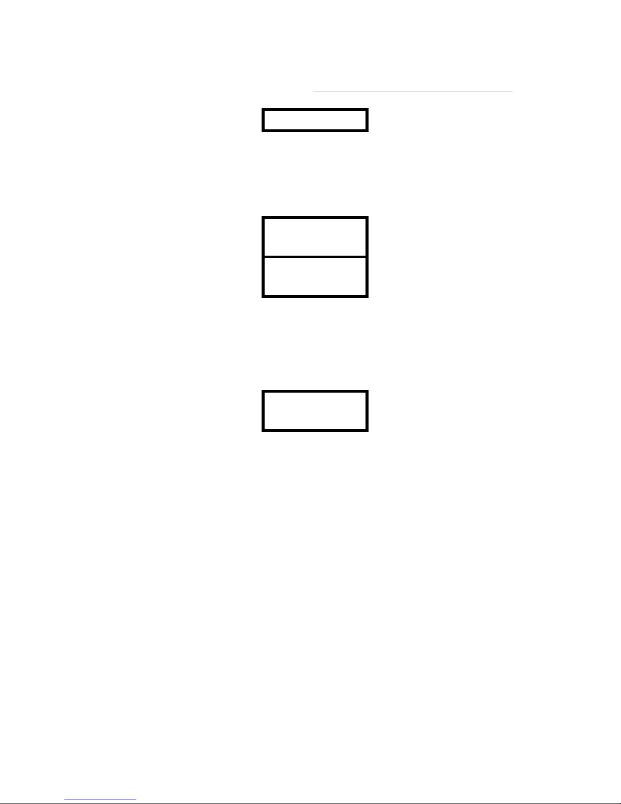
• EXAM Mn: Shows us the assignation, status and level of the selected master. Example: Exam
of the master 1, M1. In the display, we can see that the M1output is at 100%, that its assignation
is a preset 56 and has a fade time of 15 seconds. Furthermore we can see the stored channels of
the preset 56, in this example the channels 1, 2 & 3 at 100% (1-3 @100%):
M1 56 C 1-3
Page 21
User Manual - Lesson 3 - Layout & Basic Functions
LT & 15
F ×15 @ F
• EXAM FL-MT: Shows us the assignations of all the Masters, including its charged page
number. In the example display, we can see that the charged page is 901, that M1 has the preset
1 and that it is at 96%, That M2 has a channels group and that it is at 83%… Pushing the àà
key, we can access to M3 and M4 information, and then up to M12. To see the assigned times
push the ↓↓ key.
P901 P 1 GRP
M1 @ 96 83
↓↓
P901 P 1 GRP
M1 × 2.0 3.1
• 900 EXAM: Shows us the list of recorded pages.
• 9## EXAM: Shows us the information about the selected page 9##. In the example, the
information about the page 901, thus the M1 has the preset 1 and a fade time of 2 seconds, and
the M2 has a group and a fade time of 3.1 seconds. To access the information about M3..M12
press the àà key, as many times as will be necessary.
P901 P 1 GRP
M1 × 2.0 3.1
Page 22

User Manual - Lesson 3 - Layout & Basic Functions
16 & LT
MAIN MENU
In the TRITTON console, many of the editing, set-up & test functions are implemented into the
menus. This permits us eliminate a great number of dedicated keys.
The menus are a very simple use, for menus we have:
• The arrow keys (4), or cursors, they permit us to advance by the screen, selecting the functions.
• The ENTER key, to enter/exit of the menu options.
• The numerical keyboard permits us to enter the numerical data, for the edit and set-up process.
• In any cases, the INSERT key permits us to access to certain options, into the menus.
• When we switch on the console, in its display, the main menu appears:
nMainnSEQ >0
MDFY NUM ->
In the main menu there are the next functions:
1. SEQ: To edit the sequence.
2. MDFY: To modify presets & groups.
3. NUM: To edit the manual field in small numerical editor.
4. ->: To access to the second page of the main menu.
5. DEL: Deleting the sequence completely.
6. TEST: In this we can find hard and soft tests.
7. SETUP: Console configuration. Including the Patch, MIDI port, scrollers and other user
options.
8. ->: To return to the first page of the main menu.
The first command, in each menu, is its own name, in this case Main, this first command permits us
to exit to the previous menu, and always it written in tiny letters. In this case, the Main menu is a
first menu and this command has not function.
In the drawing, we can see that there are two cursors, nMainn, to both sides of the selected
option, you can displace these cursors with the arrows keys. Then, to select one menu option, for
example SEQ, press the key: ‘àà’ one time, in the display: nSEQn, to enter in this option press
ENTER key.
Page 23
User Manual - Lesson 3 - Layout & Basic Functions
LT & 17
EDITOR FOR THE MANUAL FIELD: zz NUM zz
When we need more precision to adjust the channel level, TRITTON has a little editor for the
manual field from the numerical keyboard. For example, when we work with scrollers or moving
lights this tool is very used.
From the Main menu, select the option NUM:
Main SEQ >0
MDFY nNUMn ->
In the display:
C +
>0
@ - :
To the right of the display are the symbols that indicate us the new functions for the cursor keys.
These functions only are actives when this display are present.
To the left of the display is the command line.
The new functions, for the cursors or arrow keys, are:
Arrow Up, + : Permit us add one channel/group of the selected group.
Arrow down, -: Permit us eliminate one channel of the selected group.
Arrow right, : : Permit us create a channel range.
Arrow left, @: Permits us assign a level for the selected channels group in the editor. Enter
this level with two digits.
Examples:
• Select the channel 1 at 75%.
The first entered number is always a channel number.
Press the keys: 1 ßß 75 .
In the command line: C 1@75.
• Select the channels 5-20 at 56%.
Press the keys: 5 àà 20 ßß 56 .
In the command line: C 5:20@56.
• Select the channels 16, 18, and 20-24 except the 23 at 15%.
Page 24

User Manual - Lesson 3 - Layout & Basic Functions
18 & LT
Press the keys: 16 áá 18 áá 20 àà 24 ââ 23 ßß 15 .
In the command line: C 16+18+20:24-23@15.
• Select the channel 23 at 100%.
Press the keys: 23 ßß ßß .
In the command line: C 23@F.
To obtain the level 100% (Full), press the ßß key ( @ ) two times.
• Select the channel 24 at 5%.
Press the keys: 24 ßß 05 .
In the command line: C 24@5.
To obtain the level < 10%, enter this level with two digits: 0#.
The last action done in the editor is erased pressing C.
To exit the editor press ENTER.
Note: The editor of manual field has the same functioning that the faders of the manual field,
included the functioning in “Double” mode.
LEVEL: FINE ADJUSTMENT
The user can do a fine adjustment (0-255), with more precision that the numeric entry, after to enter
a level (by numeric keyboard) and before to press other key:
The up and down arrows permit us to do a fine adjustment about the entered level.
Page 25
User Manual - Lesson 3 - Layout & Basic Functions
LT & 19
PRESETS & GROUPS MODIFICATION
It is possible to change the group or preset content editing it newly with other information
(overwrite), or modifying its content with the MDFY function.
To overwrite the preset number # we must:
• Edit the desired scene.
• # REC. TRITTON ask for a confirmation. REC to confirm. The preset # has been stored with
the new scene.
To overwrite the group in the master # we must:
• Edit the desired scene.
• LOAD Mn. The group in the master # has been stored with the new scene.
Using the MDFY function it is possible to modify presets and groups totally or partially. The
MDFY function is in the first page of the main menu. To select it, displace the cursor using the
arrows keys and press ENTER to accept it.
Main SEQ >0
nMDFYn NUM ->
To modify the preset number # we must:
• # nMDFYn ENTER
To modify the group or preset in the master # we must:
• nMDFYn ENTER Mn
Now, a new working mode is activated, the modification mode, this mode permit us to do the
needed modifications and store them. During this mode is active, in the display you can see:
nRECn ESC NUM
Mdfy GRP
These options permit us to store the modifications (REC), to quit without store them (ESC) and
access to the numerical editor (NUM) in a temporal mode to adjust channels.
In the inner line, you can see the item that TRITTON is modifying. The preset are identified by their
number (Mdfy 23) and the groups with the label GRP (Mdfy GRP).
When you access to modify a preset or group, in addition to the display options, TRITTON loads
the preset or group selected in the A manual field, and at the same time, forces at 0% to the resst of
Page 26

User Manual - Lesson 3 - Layout & Basic Functions
20 & LT
the console outputs. In this way, only the preset or group selected to modification mode is active in
scene. In this status the SG-DB LED is blinking to shows us that the modification mode is active.
Now we can use the channel faders or the numerical editor (NUM) to do the desired modifications.
When the preset or group is satisfactorily modified, press nRECn ENTER to store the changes
or press nESCn ENTER to quit without store the modifications.
Resume:
# nMDFYn ENTER {modifications} nRECn ENTER
nMDFYn ENTER Mn {modifications} nRECn ENTER
Note:
When you access to the numerical editor (NUM) from MDFY, in the NUM display you can see the
flag Mdfy, this flag informs us that the modification mode is active. When you quit of the NUM
menu pressing ENTER, you return to the MDFY menu.
Page 27

User Manual - Lesson 3 - Layout & Basic Functions
LT & 21
Summary:
SG.DB
Selects the single or double modes for the manual
field.
DELETE SG.DB
Erases the manual field output.
LOAD Mn
Loads the scene, like a group, in the selected master.
REC
Stores the scene like a preset N+1
## REC Stores the scene like a preset # (1-799).
## DELETE
Erases the selected preset.
0 DELETE
Erases all the stored presets.
## LOAD Mn Loads the preset # in the selected master.
## LOAD LOAD Loads the correlative presets, from the #, in all the
masters.
0 LOAD Mn
Clears the assignations of its associated master.
DELETE Mn
Clears the assignations of its associated master.
0 LOAD LOAD
Clear the assignations of all the masters.
## TIME Mn Assigns a fade time # (0-999) at the selected master.
## TIME TIME Assigns a fade time # at all the masters within preset
or group.
9#### REC Records the 12 masters assignation in a page 9##
9#### DELETE
Erases the indicated page.
900 DELETE
Erases all the stored pages.
9#### LOAD
Loads the indicated page in the masters.
900 LOAD
Clear the assignations of all the masters.
nMDFYn ENTER Mn
Modify the content of the Mn
# nMDFYnENTER
Modify the preset #
Summary for EXAM functions:
EXAM EXAM
Scene output.
0 EXAM
List of recorded presets. Arrows keys for more
information.
## EXAM Preset #
EXAM Mn
Mn: assignation and status.
900 EXAM
List of recorded pages. Arrows keys for more
information.
9#### EXAM
Indicated page.
EXAM FL-MT
Assignations of all the masters, and their status.
EXAM SG.DB
Scene output from the manual field, and status of C
fader.
Page 28

User Manual - Lesson 3 - Layout & Basic Functions
22 & LT
Page 29
User manual - Lesson 4 - Masters
LT & 23
4 - MASTERS
FUNCTIONS KEYS ASSOCIATED TO THE MASTERS
There are three functions keys specially associated with the masters:
1. LOAD, Used to load/empty them.
2. TIME, Used to load/clear fade times them.
3. FL-MT, Used to choose the function of the associated keys, Mn, there are three possibilities:
• FL-MT LED at off. The Mn keys are GO keys, to start the master assignation within
preset or group. GO Mode.
• FL-MT LED at on. (Push FL-MT). The Mn keys are master flash keys in Normal
mode. Flash NORMAL Mode.
• FL-MT LED blinks. (Push FL-MT again). The Mn keys are master flash keys in Solo
mode. Flash SOLO Mode.
WORKING IN "GO" MODE
Only for masters loaded with preset or channels groups. For masters loaded with chase see the
lesson 6).
There are two basic modes working with masters:
1. MANUAL.
The movement of the master fader controls the scene output of its assignation. Thus, when the fader
is in its extreme 0% (down), there is not scene output. When the fader is in its extreme 100% (up)
its assignation is at 100% in scene (maximum level). In intermediate positions we will obtain
intermediate output levels. At the moment that the master is scene output, its LED is lit at 100%.
In this mode, the assigned fade times are not counted. The output follows the fader movement.
Page 30

User manual - Lesson 4 - Masters
24 & LT
2. AUTOMATIC
Suppose that we have a master with one preset (or channel group) but without fade time, and its
fader is at 0%. In this situation push its Mn key, (In GO mode - FL-MT LED at off), the master
assignation jump at scene, at 100%, in 0.1 seconds. Its red LED of its Mn key is lit at 100%.
If the master is at 100% and we push its Mn key, its assignation jump at 0%, in 0,1 seconds, its
LED now, is lit at 50%.
3. AUTOMATIC WITH FADE TIMES
Suppose that we have a master with one preset (or channel group) and fade time. For example, a
fade time of 5 seconds, and its fader is at 0% (down). In this situation push its Mn key, (In GO
mode - FL-MT LED at off), the master assignation fade in scene at 100% in 5 seconds. The red
LED of its Mn key, is blinking, indicating us that it is temporising. When the fade finishes the led
stops of blink.
During the automatic temporisation, in a master, if we push the Mn key again, the temporisation is
stopped. Push Mn again to restart the temporisation fade newly.
If the master is at 100% and we push its Mn key, fades out scene, from 100% at 0%, in 5 seconds.
MASTER FLASH FUNCTION
After cold reset, or initially, the FL-MT LED is off, the Flash function is deactivated:
1. Push FL-MT, one time, and its LED is on. Normal Flash Mode. In this situation of FL-MT
function, each time that we push the associated Mn of a preset or group master, its assignation
takes a 100% level in scene, release the Mn key for that its assignation take the 0% level in
scene.
2. Push FL-MT again, its LED is blinking. Solo Flash Mode. In this situation of FL-MT function,
each time that we push the associated Mn of a preset or group master, its assignation takes a
100% level in scene, and at the same time, blacks out the output of the others masters and
sequence1. In stage, only is the output of the selected master. Release the Mn key for that its
assignation take the 0% level in scene, and the output of the rest of the master their previous
levels.
( 1 ) The influence of this functions about the sequence is selected in the SETUP SEQ menu..
NOTES ABOUT THE MASTERS
• When we load a preset or group in a master, we have to place its fader at 0%, to avoid light
jumps in scene.
• When we load an assigned master, the new assignation is active directly, it is not necessary
remove its previous assignation.
Page 31

User manual - Lesson 4 - Masters
LT & 25
• When we load a masters page, the faders at 0% accept their new assignations automatically. The
faders with level different at 0% (with scene output), marked with one asterisk, * (in the exam
displays), take its new assignation when they are moved at 0%.
• When one master is temporising, the LED of its Mn key is blinking, its output level and fader
level is not equal. The master is nailed. This situation is marked with the symbol "<". At any
time of the its temporisation, we can take manual control about the master output: Move the
fader up to reach the master output, moment in which will be heard a 'beep', indicating that we
have manual control about the master output.
• With the Mn keys in GO mode, if the fader is out of its 0%, the fade always is from the current
level up to 100% level, with the proportional fade time.
Summary:
FL-MT (LED off) Mn
GO. Starts the fade of the master assignation,
counting the possible assigned time.
FL-MT (LED on) Mn
Normal Flash. When Mn is pushed its output is at
100%.
FL-MT (LED blinking) Mn
Solo Flash. When Mn is pushed its output is at
100% and the output of the rest of the masters is
0%.
Page 32

User manual - Lesson 4 - Masters
26 & LT
Page 33

User Manual - Lesson 5 - Main Menu - The Sequence
LT & 27
5 - THE SEQUENCE
THE SEQUENCE
Various steps form the sequence, TRITTON has a maximum of 1000 steps for its sequence. In all
step, we can have:
• A preset.
• A fade-in time.
• A fade-out time for the previous step.
• A delay time.
• A jump at other sequence step/preset.
When we replay the sequence, in manual mode, automatic mode or temporised automatic mode, the
sequence steps are gone happening in scene of the following form:
The sequence step, or the preset that it is in the X1 step (normally in stage) fades out at 0%, while
the preset of the step in X2 (next preset in scene) fades in scene from 0% up to 100%. This double
fade is named like crossfade. When the X2 step is at 100%, its preset advances to X1, and the next
step in the sequence advances to X2. The sequence is prepared to begin a new crossfade between the
steps in X1 and X2. In this way, we can say that the sequence is a succession of crossfades.
In TRITTON, these crossfades, by default, are dipless0.
The preset 0 is always the preset of the 0 step (blackout preset). It is not possible to change the
preset of this step, but we can edit fade times, delay time and step jump.
WORKING WITH THE SEQUENCE
With the EX-AM function we can obtain information in the display:
• EX-AM GO: Access to the current crossfade information.
To create the sequence we have to store the desired presets. The console included in the sequence
all stored preset in numerical order 1.
The edition of the sequence is detailed in the next part.
There are three ways of sequence reproduction:
1. Manual.
In this mode, we only work with the X1 & X2 faders. The recorded sequence times are not
computed.
Page 34

User Manual - Lesson 5 - Main Menu - The Sequence
28 & LT
As initial situation, suppose we have the X1 & X2 faders in their lower position. These faders are
inverted, when X1 is in its lower position, has its maximum level, at 100%, and when X2 is in its
lower position is at 0%. In this situation the X1 preset is in scene, and the X2 preset is waiting to
fade in scene. We can move the faders at the same time or not. Note that the X1 & X2 presets
respond to the movements of their faders. The crossfade finishes when the two faders reach their
upper position. In this moment the X2 step (preset) jump to X1 and the next step in the sequence
jump to X2. The next crossfade is ready. The scale of these faders have been inverted, now, X1 is in
its 100% and X2 in its 0%.
The green LEDS marked likes X1 & X2, show us the direction of the needed movement to finish the
crossfade:
• If X2 is lit, move the faders at their upper position.
• If X1 is lit, move the faders at their lower position.
In any time, we can press the GO key, starting the crossfade automatically. In the same way, when
the crossfade is in automatic mode, we can take manual control with the faders.
2. Automatic without stored fade times.
In this mode the GO & GO-BACK keys are used. Not store fade times in the sequence.
Each time that we press the GO key, the sequence advances one step. There is not a real fade
because we have not stored fade times.
Each time that we press the GO-BACK key, the sequence goes back one step.
3. Automatic with stored fade times
It is the more complete mode to reproduce the sequence. The associated function keys are GO, GO-
BACK and PAUSE.
Place the X1 & X2 faders are in their lower positions and the sequence with the 0 step in X1 and 1
step in X2:
When we press the GO key, the X2 step, the 1, starts its fade to scene during the stored fade-in time,
Tin. And the X1 step, in this example the 0, starts its fade from scene during the stored fade-out
time, Tout, (this time is in the X2 step). The X2 LED shows us the direction of the faders
movement to finish the crossfade in manual mode, during the automatic crossfade this LED is
blinking. At the end of the crossfade, the X2 step (preset) jump to X1 and the next step in the
sequence jump to X2. The next crossfade is ready. The X2 LED does not blink.
If we have programmed a delay time2, Tauto, the step 1 will stay in scene this time, when this delay
time finishes, the next crossfade begins. If there is not delay time, the new crossfade begins with a
new GO. During the delay time, one LED is lit and the other LED is blinking (X1 & X2).
At any time during the crossfade, we can press GO. In this moment a next step enters in X2
immediately.
If during a crossfade we push PAUSE, the crossfade is stopped. To restart the crossfade press GO
or press GO-BACK.
If we push GO-BACK the crossfade is restarted in inverted direction. We can press this key , as
many times as will be necessary.
Page 35

User Manual - Lesson 5 - Main Menu - The Sequence
LT & 29
The displacement of the sequence
There are two modes to interrupt the sequential order of the crossfades, one programmed, editing
jumps in the sequence. Basically is one indication of the next step to fade after the step with the
programmed jump. For example, in the step 56, enter a jump to step 1 (J1), so, when the step 56 is
in scene the next step will be the step 1 (now in X2). And other with the INSERT function. With
this function, at any time, we can:
• Enter the step number and press INSERT GO: Inserting in X1 (scene) the indicated
step.
• Enter the preset number and press . (dot) INSERT GO: Inserting in X1 (scene) the
indicated preset. If this preset number is in more than one step, in X1 is located the first
step with this preset.
• Enter the step number and press INSERT GO-BACK: Inserting in X2 (next step in
scene) the indicated step. There is not light jump in scene.
• Enter the preset number and press . (dot) INSERT GO-BACK: Inserting in X2
(next preset in scene) the indicated preset. There is not light jump in scene.
• 1 INSERT INSERT (double click): Places the sequence in initial position.
• Enter the step number and press INSERT INSERT: places the step 0 in X1 and the
indicated step in X2.
• Enter the preset number and press . (dot) INSERT INSERT: places the step 0 in
X1 and the indicated preset in X2.
To program a jump, JUMP, or with the displacements with the INSERT function, we can use de
number of the step or of the preset. To indicate that we enter a preset number, only press •, (dot)
after the numerical data. (Format ###. ).
EDITING THE SEQUENCE
From the SEQ menu, we can edit the sequence completely. Enter in this menu and note the change
of the display.
This display shows us a numerical sheet, we have to place us in the appropriated place and enter the
desired data. In general, to move us by the "sheets" use the arrow keys, and to enter the numerical
data use the numerical keyboard.
Select the SEQ command in the main menu: Push the àà key, (nSEQn, placing the cursors in the
command SEQ), and press ENTER. Note we have a new display.
In this display the sequence sheet is showed, in the console we only can see two sequence steps.
This display with the empty sequence is:
nS0 nP0 J
S1 P J
Where by columns we have:
Page 36

User Manual - Lesson 5 - Main Menu - The Sequence
30 & LT
1.- Information about the sequence step we are editing, S# or Step #, this column can not be editing.
2.- Information about the step preset. P#
3.- Step number (or preset number -j-) that it will follow in the sequence to the step that we are
programming. Jump: J #.
Press the àà key 3 times, we pass to the second display for these steps:
n↓ n↑ °
↓ ↑ °
4.- Fade-out time for the previous step in seconds. (↓)
5.- Fade-in time for this step in seconds. (↑)
6.- Delay time for this step in seconds. (°)
Move the cursor with the arrow keys (cursors) at the desired position, and enter the desired
numerical data:
à: Moves the cursor one position to the right, from the last position goes back to the first position
of the same step.
ß: Moves the cursor one position to the right. Not changes of step.
↓: Moves the cursor to the next step.
↑: Moves the cursor to the previous step.
Example: Edit the step 1 with the preset 1, a T.out of 2 seconds, a T. in of 0.5 seconds, a T.Delay of
3 seconds and a Jump at step 0:
S 1 P 1 J0
↓ 2.0 ↑ 0.5
o
3.0
Place the cursor in the cell P, with the cursors, and enter 1.
Press à, now we are in cell J. Enter the number 0.
Press à, now we are in cell ↓↓. Enter 2.
Press à, now we are in cell ↑↑. Enter 0.5.
Press à, now we are in cell o. Enter 3.
The step 1 is edited.
Repeat this process for all steps we want edit.
To exit of this editing menu and stored the data, press ENTER key.
Page 37

User Manual - Lesson 5 - Main Menu - The Sequence
LT & 31
Notes about the sequence:
• If we have active the Setup option FIXED1 sequence, each time that we store a preset, this is
enter in the sequence automatically, in numerical order. If the sequence is FREE, we have to
enter the preset by edition.
• The INSERT key is used in the editing of the sequence to insert the next recorded preset to the
previous step preset, always located in the cell P. If we are in a time cell, the INSERT function
will copy the times of the previous step.
• To erase an edited time, press 0 or DELETE with the cursors around it.
• The step 0, always has the preset 0.
• The steps are not editable, cell S. From this column, enter a step number and press à to go to
the indicated step. It is a "localisation" function.
• In the columns S or P, when we press DELETE, we erase the complete step.
• To insert one preset in the sequence, locate the cursors in the step that we want have the new
preset, in the cell P, enter the preset number and press INSERT.
• To cancel a numerical enter, before store it, press C.
• The times can take values from 0 seconds to 999 seconds, though the times of 3 numbers will
not be able to have decimal part.
• INSERT function for the edition of the sequence:
In the cell P (preset), when we press INSERT the next recorded preset is inserted (in numerical
order with reference to the pervious step).
In the cell ↑ (time in), when we press INSERT, the time in of the previous step will be copied.
In the cell ↓ (time out), when we press INSERT, the time out of the previous step will be
copied.
In the cell º (delay time), when we press INSERT, the delay time of the previous step will be
copied.
• In the sequence visualisation, a jump to one step is showed like J###, and a jump to one preset
is showed like a j###.
NOTES FOR SETUP AND SEQUENCE
In this lesson you can find marks like this: 1. In this part, these marks, about the setup options, are
explained. (See the lesson ‘SETUP, Systems Configuration’):
From the SETUP menu, there are two submenus about the sequence options: SEQ and XF:
0.- The ‘dipless’ characteristics can be inhibited: SETUP Xfon: ON OFF
1.- To avoid that the systems inserts the stored preset in the sequence: SETUP SEQ RECfixed:
FIXED FREE.
2.- To deactivate the delay time: SETUP SEQ T oon: ON OFF
Page 38

User Manual - Lesson 5 - Main Menu - The Sequence
32 & LT
ERASING THE SEQUENCE: DEL
To erase the sequence access to the DEL command, from the main menu:
MainnDELn
>0
TEST SETUP ->
Select DEL command and select the SEQ option. This command needs confirmation.
Page 39

User Manual - Lesson 5 - Main Menu - The Sequence
LT & 33
Summary:
GO
Starts the new crossfade.
GO-BACK
Starts the crossfade in inverted direction.
PAUSA
Stops the current crossfade.
Nº INSERT GO
The indicated step goes to X1. Light jump.
Nº INSERT GO-BACK
The indicated step goes to X2. No Light jump.
Nº INSERT INSERT
Deactivates the sequence, and the indicated step goes
to X2.
1 INSERT INSERT
Deactivates the sequence, and the step 1 goes to X2.
Initialisation.
INSERT INSERT
Deactivates the sequence, and the step 0 goes to X1.
No modification in X2.
Nº preset . INSERT GO
The indicated preset goes to X1. Light jump.
Nº preset . INSERT GO-BACK
The indicated preset goes to X2. No Light jump.
Nº preset . INSERT INSERT
Deactivates the sequence, and the indicated preset
goes to X2.
0 . INSERT INSERT
Deactivates the sequence, and the preset 0 goes to
X2.
EXAM GO/GO.BACK/PAUSE
Access to the sequence exam display.
Page 40

User Manual - Lesson 5 - Main Menu - The Sequence
34 & LT
Page 41

User Manual - Lesson 6 - The Chases
LT & 35
6 - THE CHASES
THE CHASES
Various steps form a chase, the steps are not limited. The steps are done with presets, groups or
channels.
In TRITTON, we can store 99 chases, named like 801-899, and we can reproduce up to 6 chases in
the same time. (12 for TRITTON-36, and 18 for TRITTON-48).
For one chase, we can define:
• Its steps and if these steps are of channels, groups or presets.
• The step time (time for the step in scene).
• Direction for the chase operation. There are 3 directions:
• In crescent direction, >,
• Decrescendo direction, <,
• And cyclic, <>.
• The chase mode. There are 5 modes:
• ´Hard 1’, _| , the step goes-in scene in flash mode and goes-out scene in flash mode.
• ‘Hard 2’, / |, the step goes-in scene with a slow-ramp and goes-out scene in flash mode.
• ‘Hard 3’, | \, the step goes-in scene in flash mode and goes-out scene with a slow-ramp.
• ‘Hard 4’, / \, the step goes-in scene with a slow-ramp and goes-out scene in the same
way.
• ‘Soft’, XX. The step goes-in scene with a slow-ramp. At the same time the previous
step goes-out scene with a slow-ramp (it is like a crossfade).
The ‘soft’ mode is the unique mode that permits has two steps of the chase in scene.
The chases are play in the masters, using 2 consecutive faders (and their associated keys) to control
each chase.
STORING A CHASE
To store a chase:
Enter the chase number: 8##.
Press REC.
The console answer us if the steps are of preset, grupos or channels:
Page 42

User Manual - Lesson 6 - The Chases
36 & LT
nPRESnCHAN
GRPS
Select the desired step type. Next, in the display:
802nT0.0n> _
P
The form of editing the chase, it is similar to the employee in a "data sheet", and to the already
explained for the case of the sequence. Remember that the arrow keys permit us mover us to the
desired cells and the numerical data are entered from the numerical keyboard.
In the display, from left to right:
Cell 1.- It is the chase number we are editing or modifying (802), under this number there is a flag
shows us if the chase is from preset (P), groups (G) or channels (C).
Cell 2.- It is the step time. The time chase depends of the number the steps. (T0.0)
Cell 3.- It is the direction. Right, left or cyclic. To select the desired direction, places in this cell and
press INSERT. (>).
Cell 4.- It is the chase mode: there are 4 "hard" modes and 1 "soft" mode. To select the desired
mode, places in this cell and press INSERT. ( _)
By this upper line we move us with the arrow keys àà & ßß.
Pass to the lower line with ↓↓ key, in this line we can find or edit the numbers of the presets or
channels of the chase. The steps assignation. These steps are in order from left to right. By the steps
we move us with the arrow keys àà & ßß.
Example: Suppose we want stored the chase 805, for preset, "soft" mode, cyclic, with the presets, 1,
3, 5, 7, 5, 8, 9 & 9, in this order. If we want a chase time of 1 minute, or 60 seconds, (each step 7.5
seconds - 60/8 is the step time). To store this chase:
• 805 REC
• nPRESETn ENTER
• Pass to the cell nT0.0n and enter 7.5. (Display: nT7.5n).
• Pass to the cell n>n and press INSERT INSERT, the symbol <> will appear.
• Pass to the cell n _n and press INSERT INSERT INSERT INSERT, the symbol XX will
appear.
• ↓↓. Now we can insert the desired presets:
• 1, àà.
• 3, àà.
• 5, àà.
• 7, àà.
Page 43

User Manual - Lesson 6 - The Chases
LT & 37
• 5, àà.
• 8, àà.
• INSERT (or 9 and à), and
• 9, àà.
Now the chase is programmed. To exit press ENTER.
Copying a chase
Copy the chase 802 like a chase 810:
• 802 REC
• Over the cell n802n press 810 (if it is necessary modify the new chase 810)
• Press ENTER.
Now there are the chase 802 & 810.
Notes about the chase edition:
• When we are editing the preset for the chase, we can enter the preset/channel number or press
INSERT key to insert the next number preset/channel/group. Maintaining the INSERT key
pressed, we insert presets/channels/group, without need of displacing us with the arrows.
• To clear one step, press DELETE (over this step).
• To clear a step time, press DELETE (over this time).
• The step time by default is 0.1 seconds or "CUT" time.
• Each time that we move the cursors the previous entry is stored.
• C key erases the numerical data no stored.
• The step time can be from 0 seconds up to 999 seconds, though the times of 3 characters have
not decimal part.
Chases of groups
To store a group in a chase step, we can:
Select the desired chase step, with the cursors.
Prepare the desired scene.
Press LOAD. In this moment the console output is stored like a group in the selected
chase step. Move the arrows to edit other step.
Or we can:
Page 44

User Manual - Lesson 6 - The Chases
38 & LT
Go to the end of the chase, (the first empty step).
Prepare the desired scene.
Press INSERT. In this moment the console output is stored like a group in the selected
chase step, and the system is ready in the next step.
General notes:
To load one group you can use LOAD or INSERT (in the last step).
During of edition of the chase the LOAD key doesn’t work out this chase edition.
In the groups chases, because of the chases haven’t reference number, in the chase steps appears the
step number.
THE CHASES IN THE MASTERS
The chase uses 2 consecutive masters for its control:
The odd master is the level control master for the chase output. (0 - 100%)
The even master is the speed control master for the chase. (CUT: 100%, STORED TIME: 50% and
HOLD: 0%).
The Mn key associated to the odd master, M
odd,
starts the stopped chase or stops the active chase,
(GO-chase).
The Mn key associated to the even master, M
even
is to execute the chase step to step, each time that
you press its M
even
the chase advances one step.
The flash master function does not work in the Mn keys associated to a chase.
Loading a chase in masters.
• 8## LOAD Mn. (The M
impar
LED is lit)
All Chases are loaded with its level control locked at 100% and its speed control locked at 100%,
in this way it is not necessary displace the masters to reproduce the chase.
Removing a chase in masters. There are three options:
• 800 LOAD Mn
• 0 LOAD Mn or
• DELETE Mn
Information about the chases:
Page 45

User Manual - Lesson 6 - The Chases
LT & 39
• EX-AM Mn: Information about the chase loaded in the selected masters:
M1 C801 > T2.0
78 STOP /\ P1
Where: M1 is the master name with the charged chase; C801 is the chase number; > is the direction
of the chase; T2.0 is the step time; 78 is the chase output level; STOP is the speed; /\ is the chase
mode and P1 is the current preset in scene (or c1 for the channel chase).
• 8#### EX-AM: Information about the chase 8##.
• 800 EX-AM: Information about all stored chases.
Erasing a chases from the console memory:
• 801 DELETE.
Other functions for the chases:
• Modd: Stars the chase. The first step appears in scene, after the step time, this step goes out and
the next step appears in scene... After the last step, the first step appears again. The Modd LED
is blinking. If the chase is active, when we press the Modd key, the chase is stopped and
deactivates, and its LED is lit.
• # Modd. Stars the chase. The chase is executed # times, and after, it is deactivated
automatically.
• Meven. Chase execution in manual mode, "step to step". In this way the speed control has not
function. The user marks the step time with the Meven key. Each time that we press Meven key a
new step appears in scene. The Meven LED is lit, the Modd LED stops if is blinking. When the
chase steps fade in scene, the speed control fader controls the speed of this fade. If this fader is
at 0%, HOLD, there are not steps in scene (except in "hard1" mode, _).
• # Meven: Stars the step # to scene. The chase is in "step to step" mode.
Page 46

User Manual - Lesson 6 - The Chases
40 & LT
Summary:
8## REC
Stores 8##.
801 LOAD Mn
Loads the chase, 801, in the selected masters.
0 LOAD Mn
Removes the master assignation
8## DELETE
Erases the chase from the console memory
800 DELETE
Erase all stored chases.
M
impar
Stars / Deactivates the chase.
M
par
Executes the chase in "step to step" mode.
# M
impar
Stars and executes the chase # times.
# M
par
Activates the step #, and the chase is now in "step to step"
mode.
800 EXAM
Exams the stored chases list.
801 EXAM
Exams the chase 801.
EX-AM Mn
Exams the master assignation.
Page 47
User Manual - Lesson 7 - Setup
LT & 41
7 - SETUP
SYSTEMS SETUP
The user can configure the systems with his preferences, in the Setup menu. Each parameter of the
systems has valour by default; this valour is the adopted valour after a hard reset.
Adjust all the parameter before the programming.
Options of Setup menu:
Main SEQ >0
MDFY NUM n->n
Main DEL >0
TEST nSETUPn ->
The nSETUPn menu is in the second page of the Main menu. This menu is formed by 2 pages,
with the next options:
Page 1: nSetnPCH SEQ GM
PRH MEM MID ->
à Page 2: nSetnRST LNG CT
BEEP XF SCR ->
PCH - 24/36/48 control channels: 512 dimmer channels
Page 1: SetnPCHnSEQ GM
PRH MEM MID ->
Select the option PCH (channels patch), pressing: nPATCHn ENTER.
In Setup Patch menu:
nPatchnEDIT
DFT
c1 LF
C1
In the lower line we find information about the current patch:
• c1 appears if the patch is lineal for 24/36/48 channels, by default.
Page 48

User Manual - Lesson 7 - Setup
42 & LT
• LF appears if all channels have their LIMIT at 100%, by default.
• C1 appears if all channels have assigned the curve 1, by default.
In the upper line we find:
• Patch. To return to the previous menu (SETUP).
• EDIT. To edit the patch.
• DFT (Patch by default). To return to the default patch. After this command, always, appear the
flags c1, LF & C1.
EDIT, edits the channel patch
Select the EDIT option, in the display pressing nEDITn ENTER:
n1 nc1 LF C1
2 c2 LF C1
To edit the patch we use the format of numerical sheet, similar to the used in the edition of the
sequence and chases. Remember: Access to the desired cell and enter the numerical data.
In the display, we can see two dimmer channels at the same time. The dimmer channels, in the first
column, are not editable. We have 512 dimmer channels.
From left to right we find:
1
It is the number of the dimmer channel. This data is not editable. In the cells of dimmer channel
number we can use a displacement function:
• Enter the dimmer number we want edit.
• Press the à key. (The System goes to this dimmer channel)
Or we can displace us using ↑↑ and ↓↓ to displace us at the desired dimmer channel.
c1
It is the number of control channel that it is controlling the dimmer channel, which it is just in the
previous cell. We can enter any number from 1 up to 24, 36 or 48, respectively for TRITTON of
24, 36 or 48 control channels.
LF
It is the valour for the LIMIT function: the maximum level for the dimmer output. The dimmer
output never will be more level. You can enter valour from 0 up to 100. The 100 level is marked
like F, (full), the channels are not limited.
When we have a LIMIT different to 100%, its assigned curve is recalculate between 0% and the
LIMIT valour.
Page 49
User Manual - Lesson 7 - Setup
LT & 43
C1
It is the number of the assigned curve. There are 4 curves:
1. Lineal.
2. Square.
3. Invert square.
4. ON-OFF or Non-dim.
EDITING THE PATCH
Example 1: Control the dimmer 101 with the control channel 2. Select the curve 4, ON-OFF.
(Suppose that the dimmer 101 is connected to a discharge lamp).
• Access to the dimmer number: 101. Entering the 101 and pressing à key (or manteining
pressed the ↓ key until arriving to this dimmer channel).
• In the display:
101nc- nL- C 102 c- L- C-
• Enter the channel number (2) and press à key two times. In the display:
101 c2 LF
nC1n
102 c- L- C-
• Enter the curve number, (4). This channel dimmer is configured.
Example 2: About the TRITTON-24, suppose that we want control the dimmer channels 25, 26 &
27 with the control channels 1, 2 & 3.
• From the cell 1, enter the number 25 and press à
25 nc- nL- C 26 c- L- C-
• Press the 1 key, and the arrow-down key to move us at the next dimmer channel (26).
25 c1 LF C1
26 nc- nL- C-
Page 50
User Manual - Lesson 7 - Setup
44 & LT
• Press INSERT key. The INSERT function enters the next control channels with reference to the
control channel assigned to the previous dimmer channels. The INSERT function depends of
the cell that we are situated:
1. From a cell of the number of dimmer channel: inserts the next number of control
channel, the same valour for LIMIT and the same curve. And passes at the next number
of dimmer channel.
2. From a cell of the number of control channel: inserts the next number of control
channel and inserts he valour by default for LIMIT and curve. And passes at the next
number of dimmer channel.
3. From a cell of L or C: copies only the valour of L or C (respectively). And passes at the
next number of dimmer channel. It is necessary have assigned the control channel.
Note: If we want copy the same control channel number (that the assigned too the previous dimmer
channel), in the cell of control channel, c, maintain pressed the TIME key and press INSERT.
Example 3: Assign the dimmer channels 3-15 to the control channels 4-16. Setup EDIT:
• Access to the dimmer channel 3, and select its cell of control channel.
3 nc3 nLF C1
4 c4 LF C1
• Enter its control channel, 4, and press ↓ key.
• Press INSERT, and maintain this key pressed up to the dimmer channel 15.
15 nc16nLF
C1
16 c16 LF C1
SEQ- Parameters for the sequence
• Select the menu option SEQ, from the Setup menu:
Display 1: Set PCHnSEQnGM
PRH MEM MID ->
• Select the option SEQ, pressing nSEQn ENTER.
In the SEQ SETUP menu:
nSeqnSOLOon
Tºon RECfixed
Page 51

User Manual - Lesson 7 - Setup
LT & 45
Here, we have access to the parameters:
SOLOon/SOLOoff
This parameter can appear in these two formats. This parameter permits that a Flash Solo (in the
masters) backs out the sequence or not:
SOLOon: Activate. The Flash Solo does not black out the sequence.
SOLOoff: Deactivate. The Flash Solo blacks out the sequence.
The parameter is active by default (on).
To change this parameter, select the SOLOon option, now we can choose the desired status for this
parameter:
ON OFF
Select the desired option and press ENTER.
Tºon/Tºoff
This parameter can appear in these two formats. This parameter permits count the delay time of the
sequence or not.
Tºon: Activate (by default). The delay time is active in the sequence execution.
Tºoff: Deactivate. The delay time is not active in the sequence execution. The user have to press
GO to start each new crossfade. (The delay times are not erased).
This option is very used to test the sequence rapidly. (Only testing the crossfade times).
To change this parameter, select the Tºon option, now we can choose the desired status for this
parameter:
ON OFF
Select the desired option and press ENTER.
RECfixed / RECfree
This parameter can appear in these two formats. This parameter permits that the stored preset will be
included in the sequence automatically or not:
RECfixed At the same time that you store one preset, this preset is inserted in the sequence
(in numerical order).
RECfree: The new stored presets are not inserted in the sequence.
We can change this parameter in any time.
When we are storing presets for our sequence this parameter have to be like FIXED, and when we
are storing presets for others things this parameter have to be like FREE.
By default, we have this parameter like RECfixed.
To change this parameter, select the command and, in the new display appears:
FIXED FREE
Page 52
User Manual - Lesson 7 - Setup
46 & LT
Choose the desired option.
GM - General Master parameters
Select the GM (option in Setup menu):
Display 1:
Set PCH
SEQnGMn
PRH MEM MID ->
• Select GM, with the arrow keys.
• Press ENTER.
In the display:
nGmnCH-0
BLKOUTenabled
The General Master fader (GM) controls the general output of the console. By default, this fader
controls all the channels, except the scrollers channels. This fader has associated one black out key,
B.O. to deactivate the console output. When this function key is active, its LED is lit, there is not
console output. The program in the console is active.
Configuration about GM fader and B.O. key.
CH
TRITTON permits us exclude channels of the control of the GM. Indicate the channels number that
the GM fader (and the B.O. key) to exclude:
## nCHnn ENTER
## is a number between 0 and 24 (for TRITTON-24). The excluded channels always will be the
last channels of the systems. For example, if we exclude 5 channels, (5 CH) the GM does no
control the channels: 24, 23, 22, 21 & 20. These channels are very used controlling smoke
machinery, work lights…
BLKOUTenabled / BLKOUTdisabled
This parameter can appear in these two formats. This parameter permits us deactivate the console
dimmers output whit the BO key, or not:
BLKOUTenabled: The BO key deactivates the console dimmers output .
BLKOUTdisabled: The BO key has not function.
To change this parameter, select the command BLKOUTenabled. In the display:
ENABLE DISABLE
Choose the desired option.
Page 53
User Manual - Lesson 7 - Setup
LT & 47
To see the current configuration for the GM fader and the BO key in the display:
EX-AM BLK.OUT
PRH- Preheat Function
• Select the option PRH (in the Setup menu):
Screen 1:
Set PCH SEQ GM
nPRHnMEM MID ->
• Select PRT, with the cursors.
• Press ENTER.
In the display:
nPrhnLV CAP
>0
To preheat the lamps use the "preheat" function.
There are two working modes:
LV (LEVEL)
Linear function: All channels are to the same preheating level.
## nLVn ENTER
In this moment, all the console dimmer channels are at ##%.
To erase any preheating information:
0 nLVn ENTER
CAP (CAPTURE)
Non linear function: We can capture one scene for the preheat function:
Prepare the desired scene output.
nCAPn ENTER
This scene is now, the preheating output.
For the two working modes:
The information in scene from the PRHT function is not stored in the presets.
The PRHT function, from the option LEVEL, does not affect to the scrollers.
The general master has not control about the PRHT levels.
Page 54
User Manual - Lesson 7 - Setup
48 & LT
Note: Inside the PRH menu, we can increase or decrease the preheating level with the arrow-up key
and arrow-down key.
The preheat function is not applied to the channel out of the master general.
MEM - The Show data.
• Select the option MEM (In the Setup menu)
Display 1:
Set PCH SEQ GM
PRHnMEMnMID ->
• Select MEM with the cursors.
• Press ENTER.
The Mem menu has the next options:
Page 1 nMemnEX LO
>0
REC DEL ->
Page 2 nMemnFORMT
>0
Sysx RXD TXD ->
TRITTON has 256 Kbytes to store shows. We can have various shows stored in the console. The
time used in one show storing/loading is very short. The number of shows that the console can store
depends to the own shows.
Moreover, TRITTON permits us a serial communication using the MIDI port, with a MIDI
sequencer to export or to import the show data using a MIDI "System Exclusive" known as Sysex.
In the MEM menu, we have the functions:
EX (EXAM)
To see (exam) the recorded shows in the inner data memory. In the console display will appear the
quantity of empty memory, in the next format: ‘Free ######Bytes’. To exam the recorded shows,
press the arrow-down key (or arrow-up key): ‘Show### ######B’. In this message we can see the
show number and its capacity (in Bytes). Press the arrow-down key to see the next recorded
show…
LO (LOAD)
To load one recorded show from the data memory to the active console memory:
### nnLOnn ENTER
In this process, the active console memory is actualised completely with the stored data show.
The number of the last show loaded appears at the end of the inner line of the first page.
Page 55

User Manual - Lesson 7 - Setup
LT & 49
REC
To record the current show in the memory like a show file:
### nnRECnn ENTER
The currents show is without changes.
In the show file are stored:
All presets, pages, chases, the sequence, and all the Setup Parameters.
The number of the last show stored appears at the end of the inner line of the first page.
Note: The groups or masters assignations only are stored if they are in any page.
Recommendation: Record your show periodically. In case of problems you can save a lot of
edition time.
DEL (DELETE)
To erase one stored show file:
### nnDELnn ENTER
The show file is deleted. If this show is too in the active show, remains here, only the show file is
erased.
FORMT (FORMAT)
To format the data memory for shows files. The console advises us when this process is necessary
(the first time that you want store one show) or used this command, always that you want erase all
the show files. All show file is erased:
nFORMTn ENTER
This command needs confirmation.
SYSTEM EXCLUSIVE: Sysx RXD TXD
TRITTON permits us to export show data (stored in its memory) to a MIDI sequencer (or other
console), and after, it permits us to import these data. Moreover, this functionality permits to
exchange shows between TRITTON consoles and between TRITTON and TITAN consoles.
To export or to import the show data you need a MIDI cable and a MIDI sequencer (or other
console LT). Connect the MIDI cable following the next table:
TRITTON MIDI CABLE - FUNCTION SEQUENCER or
TRITTON-TITAN
MIDI OUT >-----TXD - TRANSMISSION ------> MIDI IN
MIDI IN <-------RXD - RECEPTION -------< MIDI OUT
To export a stored show, you must:
• Connect the MIDI cable in transmission mode (see the previous table).
Page 56
User Manual - Lesson 7 - Setup
50 & LT
• Set the sequencer (or the other console) in reception mode for the System Exclusive, Sysex.
(Each sequencer has its particular way to do this).
• Press: ## nnTXDnn ENTER
Where ## is a number of a show recorded in the TRITTON memory. During the transmission in the
display you can see: Sending...
When the show data are send, TRITTON returns to the previous menu. The sequencer (or other LT
console) permits us to store the received data.
To import a show in the TRITTON memory, you must:
• Connect the MIDI cable in reception mode (see the previous table).
• Press: ## nnRXDnn ENTER
Where ## is a number of a new show that it will be stored in the TRITTON memory. During the
transmission in the display you can see: Receiving...
• Send from the sequencer (or other console) the Sysex data. (Each sequencer has its particular
way to do this).
NOTE: The transmission from the sequencer must begin after the set up TRITTON in reception
mode, but, before 4 seconds, in other way, the reception mode (in TRITTON) is deactivated in
automatically.
When the transmission is finished, TRITTON returns to the previous menu. In the memory of
TRITTON the show ## is stored.
Remember: Only a stored show in the TRITTON memory can be sent. All Sysex data received are
stored in the TRITTON memory. The System Exclusive doesn't work with the active show.
All Sysex data are available for software MIDI sequencer of PC or Mac, for hardware MIDI
sequencers and for others LT consoles, in concrete the consoles TRITTON and TITAN.
The MIDI port of TRITTON is automatically configured to execute the Sysex commands (RXD or
TXD).
MID - MIDI port configuration
Select the option MID (In Setup menu):
Display 1:
Set PCH SEQ GM
PRH MEMnnMIDnn->
• Select the option MIDI, with the cursors.
• Press ENTER.
In the display:
Page 57

User Manual - Lesson 7 - Setup
LT & 51
nnMidinnoff
>1
out CH1 INFO
on/off
This parameter can appear in these two formats. This command activates (on) /or deactivates (off)
the MIDI port:
Off: Deactivate. The MIDI port does transmit / receive MIDI commands.
On: Activate. The MIDI port transmits / receives MIDI commands.
To change this command, select the command and choose the desired option.
In/out
This parameter can appear in these two formats. Setup the MIDI port like transmitter (OUT) or like
receiver (IN).
To change this command, select the command and choose the desired option.
CH1
To set-up the MIDI channel (1-16) for the MIDI communication:
## nnCH1nn ENTER The command, now, is showed like CH##.
INFO
To exam the midi code used in the console. TRITTON has each key associated with one MIDI note,
and each fader associated with one MIDI controller. These associations can be consulted in the
INFO command (information):
MIDI code in TRITTON is:
Note 0 - 0 Controller 0 - Master C
Note 1 - 1 Controller 1 - X1
Note 2 - 4 Controller 2 - X2
Note 3 - 7 Controller 3 - GM
Note 4 - TIME Controller 4..51 - Fader C1..C48*
Note 5 - LOAD Controller 52..87 - Fader M1..M36*
Note 6 - INSERT
Note 7 - DELETE
Note 8 -
•
Note 9 -
3
Note 10 - 6
Note 11 - 9
Note 12 - C
Note 13 - 2
Page 58
User Manual - Lesson 7 - Setup
52 & LT
Note 14 - 5
Note 15 - 8
Note 16 - ↓
Note 17 -
à
Note 18 - ENTER
Note 19 -
ß
Note 20 - ↑
Note 21 - EXAM
Note 22 - REC
Note 23 - FLMT
Note 24 - SG.DB
Note 25 - BLKOUT
Note 26 - GOBACK
Note 27 - PAUSE
Note 28 - GO
Note 29..76 - C1..C48*
Note 77..112 - M1..M36*
*The MIDI code showed is generic (and compatible) for all TRITTON models.
The relation between the MIDI notes and the standard keyboard is:
C1
D1
E1
F1
G1
A1
B1
C2
D2
E2
F2
G2
A2
B2
C3
D3
E3
F3
G3
A3
B3
C4
D4
E4
F4
G4
A4
B4
Nota 36
Nota 38
Nota 40
Nota 41
Nota 43
Nota 45
Nota 47
Nota 48
Nota 50
Nota 52
Nota 53
Nota 55
Nota 57
Nota 59
Nota 60 DO CE NT RAL
Nota 62
Nota 64
Nota 65
Nota 67
Nota 69
Nota 71
Nota 72
Nota 74
Nota 76
Nota 77
Nota 79
Nota 81
Nota 83
Nota 37
Nota 39
Nota 42
Nota 44
Nota 46
Nota 49
Nota 51
Nota 54
Nota 56
Nota 58
Nota 61
Nota 63
Nota 66
Nota 68
Nota 70
Nota 73
Nota 75
Nota 78
Nota 80
Nota 82
C#1
D#1
F#1
G#1
A#1
C#2
D#2
F#2
G#2
A#2
C#3
D#3
F#3
G#3
A#3
C#4
D#4
F#4
G#4
A#4
NOTAS - CANALES
G7
A7
B7
C8
D8
E8
F8
G8
Nota 115
Nota 117
Nota 119
Nota 120
Nota 122
Nota 124
Nota 125
Nota 127
Nota 116
Nota 118
Nota 121
Nota 123
Nota 126
G#7
A#7
C#8
D#8
F#8
• • •
• • •
• • •
• • •
C-2
D-2
E-2
F-2
Nota 0
Nota 2
Nota 4
Nota 5
Nota 1
Nota 3
C#-2
D#-2
Page 59
User Manual - Lesson 7 - Setup
LT & 53
General:
• Each time we press a key, the console transmits the NOTE ON of the associated MIDI note.
• Each time the console receives one NOTE ON its associated key is activated.
• Each time we release a key, the console transmits the NOTE OFF of the associated MIDI note.
• Each time the console receives one NOTE OFF its associated key is released.
• Each time we move a fader, the console transmits the associated MIDI controller.
• Each time the console receives a MIDI controller its associated fader imitates this movement.
(It is one way to store the movements of faders in real time).
• TRITTON have Running Status, increasing the transmission velocity.
More information about MIDI in the lesson 10.
-> - To access to the second SETUP display
Select the option -> (In the Setup menu):
Display 1:
Set PCH SEQ GM
PRH MEM MIDnn-
>nn
• Select the option ->, with the cursors.
• Press ENTER.
In the display, we have the second page of SETUP commands:
Display 2: nnSetnnRST LNG CT
BEEP XF SCR ->
In this page, also it is the command -> to pass to the first Setup menu page. The first command,
‘Set’, also it is used to return at the Main menu.
Page 60
User Manual - Lesson 7 - Setup
54 & LT
RST - Warm reset
Select the option RST (In the second pages of the Setup menu):
Display 2: SetnnRSTnnLNG CT
BEEP XF SCR ->
• Select the option RST, with the cursors.
• Press ENTER.
In this moment, the console:
1. Places the sequence in its beginning.
2. Deactivates the started chases.
3. Sets up all masters at 0% level.
4. Erases the manual field information.
5. Maintains all the stored data and all the Setup parameters.
The console, now, is in a known status.
NOTE: In TRITTON also has a hardware reset. With the console in off, press: ß, and hold down
this key, and switch on the console. (For more information see the lesson 3).
LNG - Language
Select the option LNG (In the second pages of the Setup menu):
Display 2: Set RSTnnLNGnnCT
BEEP XF SCR ->
• Select the option LNG, with the cursors.
• Press ENTER.
Now, we can see the selected language. Select it and choose the desired working language. This
change only affects to the messages and information lines.
CT - Display contrast
Select the option CT (In the second pages of the Setup menu):
Display 2:
Set RST
LNGnnCTnn
Page 61
User Manual - Lesson 7 - Setup
LT & 55
BEEP XF SCR ->
• Select the option CT, with the cursors.
• Press ENTER.
Now, to adjust the display contrast, use the up & down arrows keys. We can see the result of this
adjustment in the display.
BEEP - Acoustic signal
Select the option BEEP (In the second pages of the Setup menu):
Display 2:
Set RST LNG CT
nnBEEPnnXF SCR ->
• Select the option BEEP, with the cursors.
• Press ENTER.
To activate /deactivate the acoustic signal, ‘beep’. Here, we have the commands ON (beep active)
& OFF (beep deactivate). By default we have the option at ON, active.
XF - Crossfade type
Select the option XF (In the second pages of the Setup menu):
Display 2:
Set RST LNG CT
BEEPnnXFnnSCR ->
• Select the option XF, with the cursors.
• Press ENTER.
In the display:
nnXfnnDIPLESSon
By default the TRITTON crossfade is dipless. But the user can deactivate this characteristic.
About the dipless crossfade:
The dipless characteristic is applied to the channels that are in X1 and X2 at the same time. One
channel in X1 fades up at 0% and in the same time this channel in X2 fade at 100% level. When a
crossfade is dipless this channel never has (during the crossfade) a level inferior at the level stored
in X2 (target level). Example: The channel 1 is in X1, in scene, at 75%, and it is in X2, at 80%.
When we press GO, to start the crossfade: The channel 1 is maintained at 75%, until the X2 output
scopes this level, in this moment this channel is controlled for X2 and fades at 80%.
Page 62
User Manual - Lesson 7 - Setup
56 & LT
If the crossfade is not dipless, in this same example, when we press GO, the channel 1 beginning to
fade toward 0%, until the X2 output scopes this current level. In this moment this channel is
controlled by X2.
SCR - Scrollers (colour changers)
• Select the option SCR (In the second pages of the Setup menu):
Display 2:
Set RST LNG CT
BEEP XFnnSCRnn->
• Select the option SCR, with the cursors.
• Press ENTER.
In the display:
nnScrnnEDIT DFT
PRIORIoff Scr0
From here, we can:
EDIT: Edit the scroller sheet.
DFT (DEFAULT): Whit this option we set up that all the channels are lighting channels. There are
not scrollers. In this case in the display (downright) we can see, Scr0.
PRIOIRoff / PRIORIon: To activate /deactivate the priority for scrollers, about its control mode. By
default this characteristic is PRIORoff.
To edit the scrollers sheet, select the option EDIT. In this submenu we can define that channel is a
scroller:
c1 nnLIGHT nn
c2 LIGHT
In the display, we have the scroller sheet, and from the second column we can set up the type of the
control channel (LIGHT or SCROLLER). To change the current selection, press the INSERT key.
Each time that we press INSERT this option switch between light and scroller. We can move with
the arrow keys to set up the desired channels. Press ENTER to store and exit of this menu.
About the scroller channel operation:
1. The GM or the BO key does not control the scroller channels.
2. The "preheat" function does not work with the scroller channels.
3. All the scroller channels work in LTP mode (Last Take Precedence), the last command has
priority. In the light channels the maximum level has priority (HTP mode - Highest Take
Precedence).
4. A stored scroller in one preset scopes its maximum level in the moment that the preset is
activated (in the sequence, master, and chase…).
Page 63

User Manual - Lesson 7 - Setup
LT & 57
5. A scroller channel will not lose the level reached upon deactivating the preset that contains it.
Staying in this position, until other playback takes control over it. To erase is information, we
can accomplish a warm reset, RST, or edit the channel again.
6. When we work in PRIORIon mode: The scroller channels follow a different priority mode that
the lighting channels. In this case the value that will take precedence will be:
• Manual field. (Priority 1).
• Masters. (1..12). (Priority 2..13).
• Sequence, X2 & X1. (Priority 14-15).
7. When we work in PRIORIoff mode, option by default, all the console playbacks have the same
priority, excepting the manual field.
One example working with PRIORIon mode:
Suppose that we have a scroller handled by the sequence. In any moment, we can handle its colour,
simply we should make it from a source most high-priority. To suppose that the scroller 3 is in
green colour and controlled by the sequence, will stay in scene 1 minute, in this same time we wish
that the scroller accomplishes a chase of colours, yellow, red, and blue. Simply we should program
the chase of colours and to execute it. If in any moment we wish put a colour, for example, violet,
will be able to do it from a master without the need of deactivating the chase or the sequence.
Thus upon eliminating the exit from the master, the scroller will continue making the chase of
colours.
Upon ending the chase, the scroller returns to the colour indicated by the sequence, the green.
One example working with PRIORIoff mode:
Each time that we activate a control source, and this pass of 0% to other value of intensity, actives
the scroller, and will lose its control over this output of the scroller. Thus any master triggered will
impose its level - colour on scene, the same as any step new of a chase or of sequence, and once put
this colour in scene will lose all its control over the same.
It can not be eliminated colour information, so only to give new colour.
Page 64

User Manual - Lesson 7 - Setup
58 & LT
Page 65
User Manual - Lesson 8 - Test
LT & 59
8 - TEST
TRITTON-24, TRITTON-36 & TRITTON-48 have functions of TEST, that they help us to exam
the correct operation of the console, and to isolate possible problems.
We have "Software Tests" and "Hardware Tests".
SOFTWARE TEST
Select the option TEST (in the Main menu):
nnTESTnn ENTER.
In the display:
nnTestnnBUF
>0
HARD MEMORIA
VER
Here we have the next test options:
BUF (BUFFER)
This option shows us the output level of the 512 DMX channels. We can exam a concrete channel,
moving us with the arrow keys or entering the desired dmx channel number and press à key.
The information that it appears in the function EXAM EXAM, in not the same that the buffer
information, in the buffer information we see also the result of applying the curve and the limit
function.
Note: In the buffer information we have the information about the 512 output channels.
HARD (HARDWARE)
This option has a series of test options of console physical parts, as are the test of LED, the faders,
the keys... See below.
MEM (MEMORY)
This test shows us the empty RAM memory (capacity), in a format like:
XX% free memory.
Some parameters, as the number of steps of a chase, depend only and exclusively of the quantity of
available memory in the internal RAM.
To exit of this Test, press any key or wait a seconds.
Page 66

User Manual - Lesson 8 - Test
60 & LT
VER (VERSION)
This option shows us the current software version. This version is very important for maintenance
and update of the console.
To exit of this Test, press any key or wait a seconds.
Note. The software test are compatibles with the console operation.
HARD (HARDWARE TEST)
The software tests are not compatibles with the console operation. When we execute some hardware
test the console operation is stopped.
This test help us to find the hardware problems in the console:
nnHardnnINPUT MEM
DISP BEEP LEDS
INPUT
Keys and faders Test.
Enter in the INPUT HARD TEST, follow the instructions in the display. To begin, press:
• ENTER
And in the display we can see the active faders and their levels, and the name of the pressed keys.
So, press the desired keys and move the desired faders, and check their reading in the display.
This display is in white if there are not active faders or pressed keys.
Note: At the same time only we can see 4 inputs (reading).
To exit of this Test, press ENTER again.
MEM (MEMORY)
This test permits us check the memory status. It does not affect to its recorded data.
When this test is finished, appears the message: MEM OK.
DISP (DISPLAY)
To activate this function press ENTER key.
The display will appear in black (all spots are actives).
To exit of this function press ENTER again.
BEEP
To check the acoustic signal or "beep"
Page 67

User Manual - Lesson 8 - Test
LT & 61
Select the option BEEP, and press ENTER key to activate this test.
In this moment, the console emits ‘beeps’ periodically.
To exit of this test, press ENTER key again.
LEDS
To check each LED of the console.
Select the option BEEP, and press ENTER key to activate this test.
When this test is activated:
1. In the console display we can see the name of the LED in exam, the first LED is SG.DB
(LED of the upright key). This LED is fading up-down, until we exit of this test or we
check other LED.
2. The à & ß keys permit us check the next LED, or the previous LED respectively. In
the display always we see the name of the LED in exam.
To exit of this test, press ENTER key again.
Page 68

User Manual - Lesson 8 - Test
62 & LT
Page 69
User Manual - Lesson 9 - Working with Scrollers
LT & 63
9 - WORKING WITH SCROLLERS
TRITTON can work with scrollers (colour changers). These scrollers have some special
characteristics.
DEFINING ONE CONTROL CHANNEL LIKE SCROLLER
From the SETUP menu, we can define that control channel is a scroller.
SETUP SCR EDIT:
c1 nnLIGHT nn
c2 LIGHT
Place us in the desired cell, the cell at right of the control channel number that will be a scroller, and
with the INSERT key, switch between the two options (LIGHT ó SCROLLER) set up the desired
channel like scroller. See also the lesson 7.
SCROLLERS EXAM
Scroller channel:
• Press EX-AM key and press the Flash key of the desired channel.
The channel number appears in the display with a little ‘s’ (for scroller channel) or with a little ‘c’
(for light channel).
From the SETUP PATCH menu, the scroller channel also is marked with a little ‘s’.
In others words, each time that you see a little ‘s’ near the channel number, you see a scroller
number.
WORKING WITH THE SCROLLERS
The scroller output level is a colour in scene, and one colour isn't more important than other colour
(with great output level). To resolve this problem in scene, the scroller channels work in LTP
mode (Last Take Precedence), and no in HTP mode (High Take Precedence).
TRITTON has two working modes for scrollers:
PRIORIon Mode: In this mode, the playbacks of TRITTON have the next priority order:
1. Manual field
2. The masters, beginning from the master 1 and finishing in master 12 (TRITTON-24).
3. The sequence, first X2 and after X1.
PRIORIoff Mode: All playbacks have the same priority, except the manual field.
Page 70

User Manual - Lesson 9 - Working with Scrollers
64 & LT
• One scroller, controlled by the manual field, will follow to the movement of its fader, except
when the fader is at 0%, in this moment this scroller can be controlled by other playbacks. For
PRIORIoff the scroller is at 0% and without control and for PRIORIon the scroller channel
takes the level of the next playback in the priority order.
• One scroller included in a master follows the next process: In the moment that the master takes a
level >0%, the scroller appears in scene at its recorded level, in others words, the scroller take
its colour immediately (f.e.80%), in this way this scroller doesn't pass by the previous colours.
• This scroller included in the master doesn't change its output level when the master returns at
0%. In others word, the colour is maintained in scene, but this scroller isn't controlled by this
masters. (If we are in PRIORIon mode, the next playback takes its control).
• When one scroller is controlled by one chase: The scroller always is in "hard 1" mode (_) and
the scroller doesn't depend to the master level of this chase. The scroller output level changes
when the next chase step produces one change or when other playback produces the change.
• When one scroller is in X2, in the sequence, in the same moment that X2 begins its fade to
scene, the scroller takes its target level (its stored colour), this scroller doesn't fade.
It is important that the user tests with both modes and chooses your preferred mode.
Note: If we have a preset (or group) only with scroller charged in a master, we can start it with its
Flash key, it isn't necessary to move the fader, (when we release the Flash key the scroller loses its
control, but no its output level).
Note: When one channel is scene has not origin (any playback is controlling its level), its level
is not stored in the presets.
Page 71
User Manual - Lesson 10 - Working with MIDI
LT & 65
10 - WORKING WITH MIDI
The MIDI protocol (Musical Instrument Digital Interface), it is a protocol created for the musical
instruments, but today is introduced in the world of the lighting and multimedia. The
synchronisation of the all show elements is possible with MIDI.
The basic configurations using TRITTON and its MIDI, are represented in this drawing:
ORDEN ADOR
PC,
AMIGA,
MACINTOSH
INTERFACE
MIDI
MODOOUT
MIDI IN
MIDI OUT
ORDENADO R
PC,
AMIGA,
MACINTOSH
INTERFACE
MID I
MODO IN
MIDI OUT
MIDI IN
GRABACION
REPRODUCCION
MIDI THRU
OTROS EQUIPOS
MIDI
TRITTON TRITTON
The computer can be substituted with a MIDI sequencer. In this case the MIDI interfaces isn't
necessary.
The MIDI protocol permits us a time control very interesting, synchronising in a very accurate
mode, even advancing a lighting event to its music event (adjusting slow response of the lamps).
Permits us to accelerate/decelerate an event, to the same speed that the rest of the show (music,
smoke...). And above all permits that the musicians handle the lighting from a most familiar control
for them or that the illuminators start musical events from their lightboards.
The correspondence MIDI in the TRITTON console is:
MIDI Note = Console key.
MIDI Controller = Console fader.
There are not commands like Program Change, Pause, Play... or commands in real time like
"click"…
The Running Status is contemplated in this console, increasing the transmission speed.
Page 72

User Manual - Lesson 10 - Working with MIDI
66 & LT
MIDI PORT CONFIGURATION
The MIDI port is configured in the menu: SETUP MID (MIDI).
We can activate or deactivate the MIDI port. (ON or OFF respectively).
If we want that the console emits MIDI commands, select the option OUT. The entry MIDI-IN is
not active.
If we want that the console receives MIDI commands, select the option IN. The entry MIDI-IN is
active and the output MIDI-OUT is not active.
The MIDI-THRU connector always is a copy of the MIDI-IN signal. And it is used to link other
MIDI units.
The MIDI communication channel (1..16) is defined by: ## CH.
See also the lesson 7.
FOR MORE INFORMATION...
If it is the first time that we do an assembly using the MIDI synchronisation, will be very interesting
to widen information about this topic. Some publications that we consider interesting:
‘Técnicas de Interface MIDI. Música y Ordenadores Personales’. Editorial JACKSON. Author
G. Perotti.
‘MIDI systems and Control’. Editorial Focal Press. Author Francis Rumsey.
Page 73
User Manual - Lesson 11 - EXAM Function
LT & 67
11 - EXAM FUNCTION
This function permits us obtain information very interesting.
EXAM Command Display information.
EX-AM EX-AM
Output level of all channels. To see a concrete channel, enter
its number ## and press àà.
EX-AM Channel Flash key
List of preset with this channel stored.
EX-AM Mn
Content /status of the selected master.
EX-AM FL-MT
Content /status of all master.
EX-AM LOAD **Deactivate the EX-AM function.
EX-AM TIME
Help about the TIME key.
EX-AM REC
Help about the REC key.
EX-AM DELETE
Help about the DELETE key.
EX-AM INSERT
Help about the INSERT key.
EX-AM GO (PAUSE or GO-BACK)
Exam the current crossfade.
EX-AM BLK.OUT
Exam the status of GM and BO key.
EX-AM SG.DB
Exam the manual field.
EX-AM any arrow key **No function.
EX-AM any numerical key **Deactivate the EX-AM function.
EX-AM ENTER **Deactivate the EX-AM function.
0 EX-AM
List the recorded presets. Arrow keys.
### EX-AM (1..799)
Exam of selected preset. Arrow keys.
800 EX-AM
List the recorded chases. Arrow keys.
8## EX-AM (801..899)
Exam of selected chase. Arrow keys.
900 EX-AM
List the recorded pages. Arrow keys.
9## EX-AM (901..999)
Exam of selected page. Arrow keys.
• To exit of the exam display press ENTER.
• Note: You can access other information with the arrows keys.
Page 74

User Manual - Lesson 11 - EXAM Function
68 & LT
Page 75

User Manual - Lesson 12 - Special Functions/Time
LT & 69
12 - SPECIAL FUNCTIONS - TIME
‘CAPTURING’ DELAY TIMES FOR THE SEQUENCE
We can ‘capture’ the delay times, for the sequence, manually. In other words, we can press the GO
key, reproducing the sequence, as times as it is necessary, and TRITTON ‘teaches’ the time between
pressings (delay time). This delay time, Tauto, is inserted in X1 at the end of its crossfade.
If we have programmed delay times, deactivate this times (SETUP SEQ Tºoff).
Recording delay times manually:
• Press and hold down TIME and press GO. The crossfade begins, when the crossfade finish
begins the delay time, to mark its finish and the beginning of the next crossfade:
• Press and hold down TIME and press GO. In this moment the total delay time is inserted in the
step in X1 and the next crossfade begins…
• Press and hold down TIME and press PAUSE, to finish this process.
Notes:
If we have recorded fade times, these times are discounted of the delay times.
If we have not recorded fade times, and we want insert them after maintaining the time between
crossfades:
1. From the Main menu, select the option SEQ to edit the sequence.
2. Enter the desired fade times pressing and hold down TIME (TIME + ###), in this way the
inserted fade time is discounted of Tauto. The time between crossfades is the same.
Note:
In the capture processing: If the delay time is smaller than the stored fade time, the console emits a
warning ‘beep’ and the delay time is not recorded, but the storing process is not deactivate.
Page 76

User Manual - Lesson 12 - Special Functions/Time
70 & LT
‘CAPTURING’ STEP TIMES FOR THE CHASE
It is possible capture the step time for a chase manually.
Charge the desired chase in the masters (the chase can be activated or not), and:
• Press and hold down TIME and press Mpar (Step), Mpar, Mpar …as times as it is necessary,
until be sure of be the desired time for the chase.
• Press and hold down TIME and press Mimpar (Go). After this command the chase begins work
automatically, with the step time inserted manually. In concret, the new step time is the time
between the last pressing of Mpar , STEP, and the pressing of Mimpar, GO, (always with the
TIME key pressed).
In this way is very simple synchronise the chases with the music in leave or other thing, without the
necessity of edit this step time.
Page 77

Page 78

Because your
successes are
ours
www.dimmer.de
Specifications can be changed without previous notice.
 Loading...