

Page 1
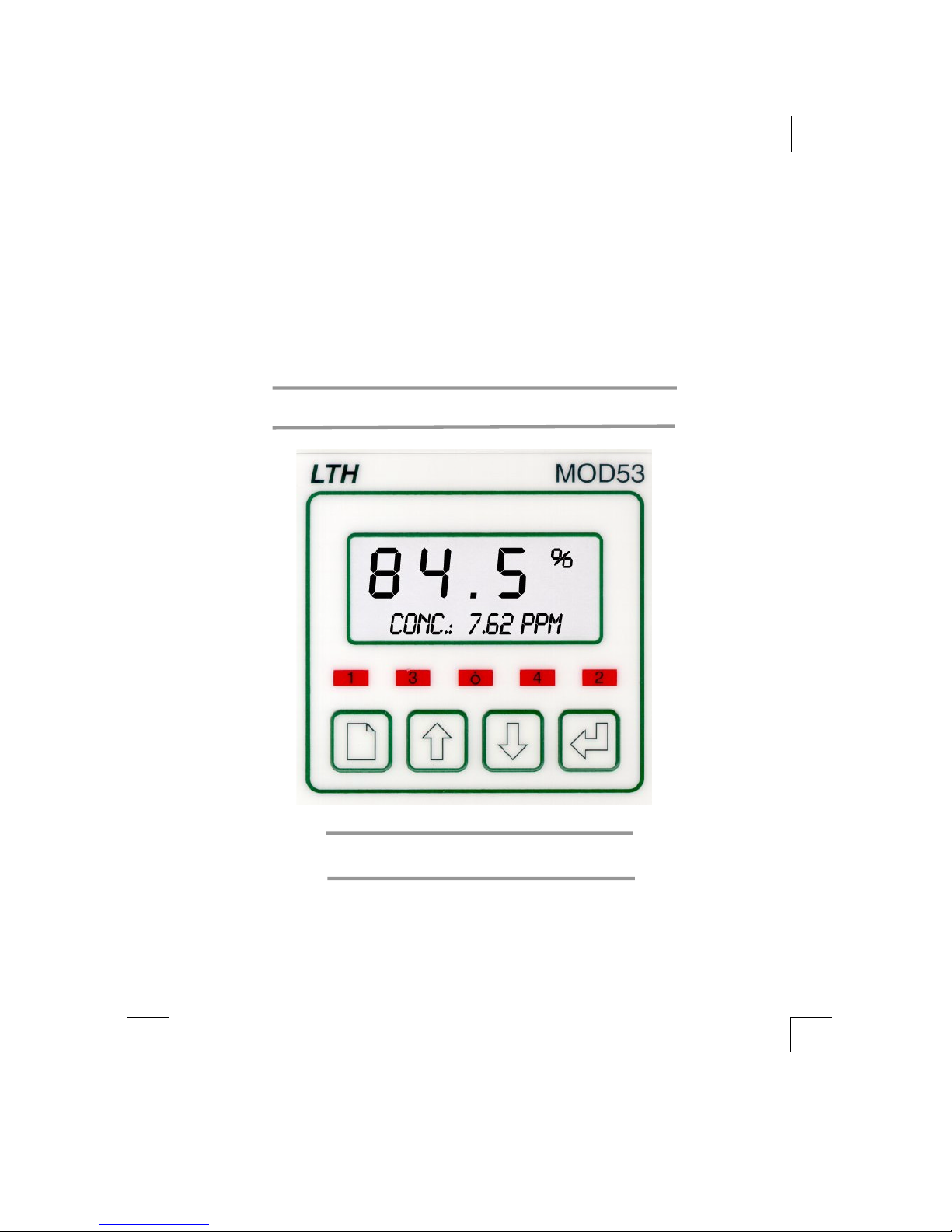
MOD53
DISSOLVED OXYGEN MONITOR
OPERATION GUIDE
Page 2

Preface
1
Preface
Product warranty
The MOD53 has a warranty against defects in materials and workmanship for three
years from the date of shipment. During this period LTH will, at its own discretion,
either repair or replace products that prove to be defective. The associated
software is provided ‘As is’ without warranty.
Limitation of warranty
The foregoing warranty does not cover damage caused by accidental misuse,
abuse, neglect, misapplication or modification.
No warranty of fitness for a particular purpose is offered. The user assumes the
entire risk of using the product. Any liability of LTH is limited exclusively to the
replacement of defective materials or workmanship.
There are no user serviceable parts, including fuses etc., within the unit. Any
attempt to dismantle the instrument will invalidate the warranty.
Disclaimer
LTH Electronics Ltd reserves the right to make changes to this manual or the
instrument without notice, as part of our policy of continued developments and
improvements.
All care has been taken to ensure accuracy of information contained in this
manual. However, we cannot accept responsibility for any errors or damages
resulting from errors or inaccuracies of information herein.
Copyright and trademarks
All rights reserved. Translations, reprinting or copying by any means of this
manual, complete or in part or in any different form requires our explicit approval.
MOD53 is a trademark of LTH Electronics Ltd
Fifth Edition August 2005
Part number : 6136
LTH Electronics Ltd
Chaul End Lane
Luton Telephone: +44 (0)1582 593693
Bedfordshire Fax: +44 (0)1582 598036
LU4 8EZ email: [email protected]
England Web: www.lth.co.uk
Page 3

Preface
2
Manufacturing Standards
Electromagnetic compatibility
This instrument has been designed to comply with the standards and regulations
set down by the European EMC Directive
Safety
This instrument has been designed to comply with the standards and regulations
set down by the European Low Voltage Directive using BS EN 61010-1 : 1993
Quality
This instrument has been manufactured under the following quality standard :
ISO 9001:2001. Certificate No : FM 13843
Note: The standards referred to in the design and construction of LTH products are
those prevailing at the time of product launch. As the standards are altered from
time to time, we reserve the right to include design modifications which are
deemed necessary to comply with the new or revised regulations.
Page 4

Contents
3
Contents
Preface..................................................................................................................1
Contents ...............................................................................................................3
1 Introduction.....................................................................................................5
About the MOD53 ............................................................................................5
Unit Specification .............................................................................................5
2 Installation – Safety & EMC............................................................................7
Wiring Installation ............................................................................................7
3 Installation – Panel Mount .............................................................................9
Top Connector ...............................................................................................11
Supply Voltage Connections..........................................................................11
Current Output Connections ..........................................................................12
Set Point Relay Connections .........................................................................12
Set Point Relays 3 & 4 Connection ................................................................13
Bottom Connector ..........................................................................................14
Sensor Input Connections..............................................................................14
Sensor Types.................................................................................................15
Temperature Input Connections.....................................................................16
Pressure Transmitter Input.............................................................................17
RC2 Cleaner Connection ............................................................................... 17
Digital Inputs ..................................................................................................18
4 Installation – Surface Mount........................................................................19
Pipe Mounting ................................................................................................20
Terminal Connections ....................................................................................21
Supply Voltage Connections..........................................................................21
Current Output Connections ..........................................................................22
Relay Connections.........................................................................................23
Sensor Input Connections..............................................................................24
Sensor Types.................................................................................................24
Temperature Input Connections.....................................................................26
Pressure Transmitter Input.............................................................................27
RC2 Cleaner Connection ............................................................................... 27
Digital Inputs ..................................................................................................28
5 User Interface................................................................................................29
The Front Panel .............................................................................................29
The Menu System ..........................................................................................30
Error Messages..............................................................................................30
Access Entry ..................................................................................................30
Unit Configuration ..........................................................................................34
6 Main Display..................................................................................................37
7 Parameters ....................................................................................................41
Units...............................................................................................................43
Sensor Type...................................................................................................44
Temperature Input..........................................................................................44
Salinity............................................................................................................44
Page 5

Contents
4
Pressure Compensation.................................................................................45
Simulated Input ..............................................................................................45
8 Set Points ......................................................................................................47
Set Point Source ............................................................................................49
Set Point Trigger ............................................................................................49
Set Point Mode...............................................................................................50
Dose Alarm Timers ........................................................................................51
Set Point 4......................................................................................................52
9 Current Output ..............................................................................................53
Input ...............................................................................................................54
Output Range.................................................................................................54
Zero & Span ...................................................................................................54
Dual current outputs.......................................................................................55
Proportional Control .......................................................................................55
Error Condition...............................................................................................55
10 Calibration ...................................................................................................57
On-Line/Off-Line Operation............................................................................59
Calibration Access .........................................................................................59
Automatic Calibration.....................................................................................59
Sensor Calibration..........................................................................................60
Temperature Calibration ................................................................................61
Pressure Input Calibration..............................................................................62
Current Output Calibration .............................................................................63
Resetting The User Calibration ......................................................................64
11 Save & Restore ...........................................................................................65
12 Pressure Input.............................................................................................67
13 Configuration ..............................................................................................71
14 Sensor Cleaning .........................................................................................73
15 Fault Finding ...............................................................................................75
16 OE15 Membrane Replacement ..................................................................79
17 Guarantee and Service...............................................................................81
Appendix A – DO Measurement .......................................................................83
Appendix B – Probe Parameters ......................................................................85
Appendix C – Factory Default Setups..............................................................87
Appendix D – Customer Setup .........................................................................91
Appendix E – Calibration ..................................................................................95
Appendix F – Temperature Sensor Data..........................................................97
Appendix G – Pressure Conversions...............................................................99
Appendix H – Oxygen Solubility.....................................................................101
Appendix I – Error Messages..........................................................................103
Index .................................................................................................................107
Page 6

1 Introduction
5
1 Introduction
ABOUT THE MOD53
The MOD53 is a microprocessor controlled dissolved oxygen measurement
instrument. It uses a multifunction LCD to display readings and provide feedback
to the operator. Different options provide fully configurable control, alarm and
feedback with up to four relays and two 0/4-20mA current output sources.
UNIT SPECIFICATION
Sensor Input Galvanic (Mackereth) 0 to 9.999mA or Polargraphic
(Clark) 0 to 500.0nA.
Sensor Bias Voltage Software Programmable, -1.000 to +1.000V,
Resolution ±1mV, Output Accuracy ±3mV
Sensor membrane
correction factor
Software Programmable
0 to 9999
Sensor Cable Up to 100 metres
Ranges of
Measurement
0 - 199.9 % saturation, 0 - 30.00 ppm Concentration,
0 – 999.9 mmHg (Calibration specific)
0 – 9999 mBar pO
2
(Calibration specific)
Accuracy
±3µA (Galvanic Mode), ±1.0nA (Polargraphic Mode)
Linearity
±0.1% of Range
Repeatability
±0.1% of Range
Temperature Sensor 4 wire interface, operating with up to 100 metres of
cable. Software selectable sensor type including
PT100 & PT1000 RTD.
Measurement Range
-50°C to +300°C (when using PT100 or PT1000)
Temperature Accuracy
±0.2°C (Dependant on Sensor Configuration)
Operator Adjustment
(Temperature)
± 50°C, or ± 122°F
Temperature
Compensation
Automatic, or Manually set from 0°C to 100°C
Pressure
Compensation
Actively from 4-20 mA input (Direct or 24V loop
powered from the MOD53.) Software Scalable.
or User Programmable from 0.50 – 9.99 bar
With user Selectable Pressure Damping
Salinity Compensation User Programmable from 0 – 40.0 ppt
Ambient Operating
Temperature
-20°C to +50°C (-4°F to +122°F) for full specification.
Ambient temperature
variation
±0.01% of range / °C (typical)
Page 7

1 Introduction
6
User Interface Large 4 character 7-segment display for measured
value, with alphanumeric dot matrix characters for
units, information and programming. Easy to use four
button user interface for programming.
Current output
(optional 1 or 2 outputs)
Selectable 0-20mA or 4-20mA operation into a 1000Ω
maximum load, fully isolated to 2kV. Selectable
transmission of either sensor reading or temperature,
and software scalable within the operating range.
Can be configured as a clean output so that the signal
switches between 0 to 20mA.
Operator adjustment
(Current)
±1mA zero and ±1mA span for remote monitor
calibration
Set Point Relays
(2 standard, 4 optional)
Fully configurable set points with volt free contacts.
Rated 5A 30V DC / 5A 250VAC (non-inductive).
Operating Modes
(Relays 1,2 & 3)
Configurable High, Low, Band or Latch trigger
conditions, with On/Off, Time Proportioning, Pulse
Proportioning, and Cleaning modes for each relay.
Adjustable delay timers up to 10 mins, and hysteresis
in On/Off mode. Adjustable dose alarm timer to 15
mins in all modes. Adjustable cycle time and band in
“Proportioning” modes. Adjustable duration, recovery
and interval periods in “Cleaning” mode.
Operating mode
(Alarm relay 4)
The relay can be set to energise on any one of the
following instrument conditions:- Sensor alarm, Dose
alarm, Calibration, Off line, Any error
Off-Line Facility
(for calibration and
commissioning)
Initiated by remote contact closure or software
selection. Relays 1, 2 & 3 are de-energised and the
current outputs are held at the last On-Line value.
EMC : Immunity BS EN 50082-2 1995
EMC : Emissions BS EN 50081-1 1992
Safety Designed and manufactured in accordance with BS
EN 61010-1 1993
Power Supply
Optional
85 to 250V AC or DC 10W max.
18 to 36V AC or DC 15 W max
Panel Mount Housing Flame retarding ABS plastic, rated to IP66 to the front
when installed in a panel.
Weight Less than 0.6kg
Dimensions 96mm x 96mm x 140mm (H x W x D), including
connectors
Surface Mount Housing Expanded polyurethane foam rated to IP66
Weight Less than 1.5kg
Dimensions
305mm x 200mm x 82mm (H x W x D), excluding
mounting brackets
Page 8

2 Installation – Safety & EMC
7
2 Installation – Safety & EMC
This chapter describes how to install and mount the MOD53, and how to connect
the unit to a power source and auxiliary equipment.
Although today’s electronic components are very reliable, it should be anticipated
in any system design that a component could fail and it is therefore desirable to
make sure a system will fail safe. This could include the provision of an additional
monitoring device, depending upon the particular application and any
consequences of an instrument or sensor failure.
WIRING INSTALLATION
The specified performance of the MOD53 is entirely dependent on correct
installation. For this reason, the installer should thoroughly read the following
instructions before attempting to make any electrical connections to the unit.
CAUTION !
: ALWAYS REMOVE THE MAIN POWER FROM THE SYSTEM
BEFORE
ATTEMPTING ANY ALTERATIONS TO THE W IRING. ENSURE THAT
BOTH
POWER INPUT LINES ARE ISOLATED. MAKE SURE THAT THE POWER
CANNOT BE SWITCHED ON BY ACCIDENT WHILST THE UNIT IS BEING
CONNECTED. FOR SAFETY REASONS AN EARTH CONNECTION MUST BE
MADE TO THE EARTH TERMINAL OF THIS INSTRUMENT.
LOCAL WIRING AND SAFETY REGULATIONS SHOULD BE STRICTLY
ADHERED TO WHEN INSTALLING THIS UNIT. SHOULD THESE
REGULATIONS CONFLICT WITH THE FOLLOWING INSTRUCTIONS,
CONTACT LTH ELECTRONICS OR AN AUTHORISED LOCAL DISTRIBUTOR
FOR ADVICE.
To maintain the specified levels of Electro Magnetic Compatibility (EMC,
susceptibility to and emission of electrical noise, transients and radio frequency
signals) it is essential that the types of cables recommended within these
instructions be used. If the installation instructions are followed carefully and
precisely, the instrument will achieve and maintain the levels of EMC protection
stated in the specification. Any equipment to which this unit is connected must also
have the same or similar EMC control to prevent undue interference to the system.
♦ Terminations at the connectors should have any excess wire cut back so that
a minimal amount of wire is left free to radiate electrical pick-up inside or
close to the instrument housing.
♦ The terminal cover of the surface mount unit must be correctly re-assembled
and securely fastened, to maintain a continuous electro-magnetic shield
around the instrument.
N.B. The use of CE marked equipment to build a system does not necessarily
mean that the completed system will comply with the European requirements for
EMC and therefore CE marking.
Page 9

2 Installation – Safety & EMC
8
Noise suppression
In common with other electronic circuitry, the MOD53 may be affected by high level,
short duration noise spikes arising from electromagnetic interference (EMI) or radio
frequency interference (RFI). To minimise the possibility of such problems occurring,
the following recommendations should be followed when installing the unit in an
environment where such interference could potentially occur.
The following noise generating sources can affect the MOD53 through capacitive or
inductive coupling.
• Relay coils
• Solenoids
• AC power wires, particularly at or above 100V AC
• Current carrying cables
• Thyristor field exciters
• Radio frequency transmissions
• Contactors
• Motor starters
• Business and industrial machines
• Power tools
• High intensity discharge lights
• Silicon control rectifiers that are phase angle fired
The MXD53 series is designed with a high degree of noise rejection built in, to
minimise the potential for interference from these sources, but it is recommended
that you apply the following wiring practices as an added precaution. Cables
transmitting low level signals should not be routed near contactors, motors,
generators, radio transmitters, or wires carrying large currents.
If noise sources are so severe that the instrument’s operation is impaired, or even
halted, the following external modifications should be made, as appropriate:
• Fit arc suppressors across active relay or contactor contacts in the vicinity.
• Run signal cables inside steel tubing as much as is practical.
• Use the internal relays to switch external slave relays or contactors when
switching heavy or reactive loads.
• Fit an in-line mains filter close to the power terminals of the instrument.
Page 10
3 Installation – Panel Mount
9
3 Installation – Panel Mount
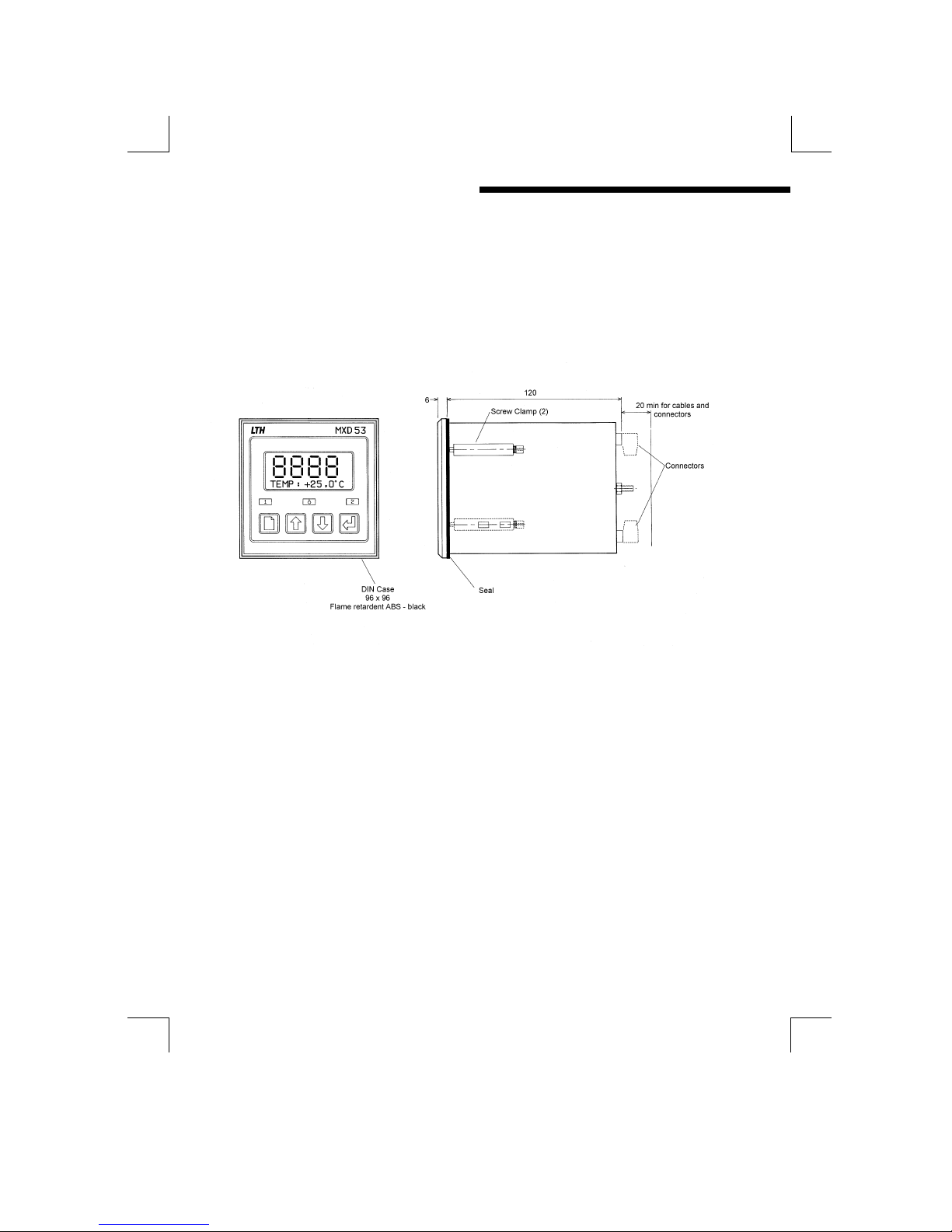
The panel-mounting version is designed to be flush mounted and sealed in a
square cut-out in a panel, and is held in place with the two screw clamps provided.
Figure 1 : Overall dimensions panel-mounting MOD53
• The panel cut-out for mounting the unit should be 92 mm x 92 mm (+1.0 – 0.0).
• A sealing gasket is supplied with the MOD53 to be fitted around the edge of the
cut-out.
• Two screw clamps are supplied and are fitted from the back of the instrument.
• Take care to ensure the gasket is correctly positioned before tightening the
clamps.
• A badly fitted gasket will not give a good seal to the specified IP rating.
Page 11
3 Installation – Panel Mount
10
Unit Connection
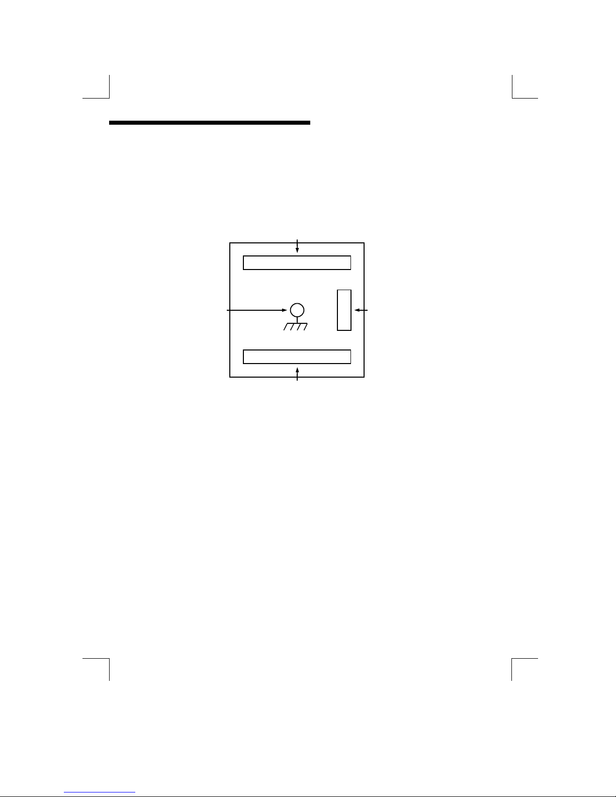
Connections to the panel-mounted version of the MOD53 are made with up to four
plug and socket terminal blocks, accessible to the rear of the unit.
Top Connector
Bottom Connector
Expansion Port
where fitted
Earth Stud
Figure 2 : Panel mount unit, rear view
The top connector houses the power input, relay and current output terminals. The
bottom connector houses the sensor input, temperature sensor input and the
digital inputs. The expansion port provides for additional enhancements such as
the third and fourth relay connection.
Page 12
3 Installation – Panel Mount
11
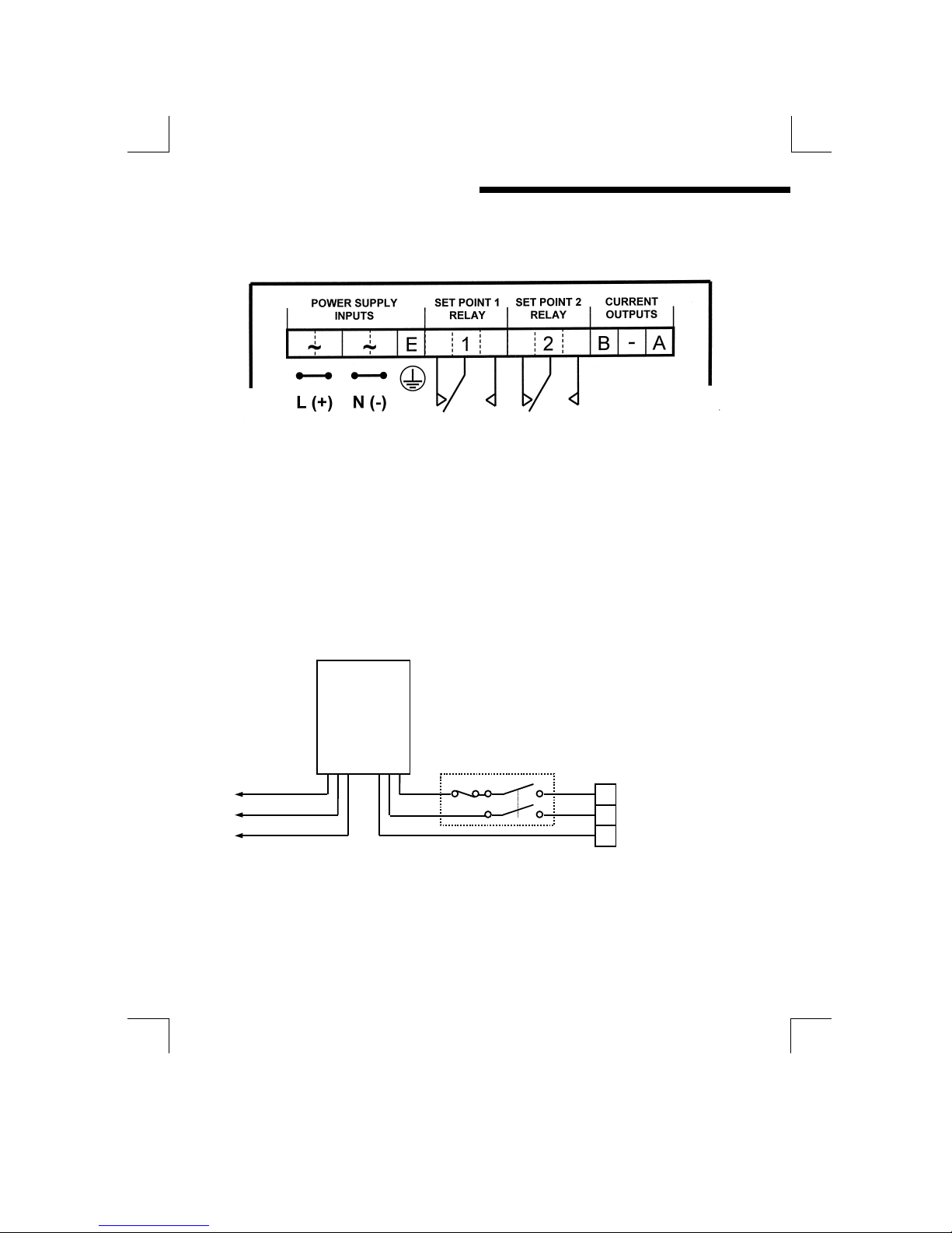
TOP CONNECTOR
Figure 3 : Panel mount unit, top connector wiring
SUPPLY VOLTAGE CONNECTIONS
The MOD53 can be powered from either an AC or DC supply voltage. The unit
provides two terminals for each of the input connections (“Live” & “Neutral” for an
AC input, or + & - for a DC Input), plus an “Earth” terminal. This allows the supply
to be “daisy chained” to the relay contacts and/or other instruments. The
instrument uses a universal power supply that accepts a wide range of voltage and
frequency inputs. Refer to the label adjacent to the power supply terminals for
the input voltage limits. Exceeding these limits may damage the instrument.
Figure 4 : Power supply connection
The power supply should be taken from an isolated spur and fused to a maximum
of 3 Amps. If the relays require greater current, then a separate 5A fuse will be
required. The incoming Earth connection must be connected to the “Earth”
terminal.
MOD53
OUT IN
3A
L
N
E
Page 13
3 Installation – Panel Mount
12
CURRENT OUTPUT CONNECTIONS
The MOD53 can be supplied with up to 2 current outputs designated A and B. It is
shipped with links across the relevant current output pins if the option is fitted. If a
current output is required, remove the link and replace with a cable terminated by a
load resistance not exceeding 1000Ω. For best noise immunity, use a screened
twisted pair cable, with the screen connected to Earth at one end. Use a
sufficiently large cable to avoid a high resistance in the overall current loop. When
either of the outputs is open circuit, in a dual output unit, the other will
indicate a fault by transmitting a 2mA signal. This will be accompanied by a
flashing error message on the Display (E41, see Appendix I)
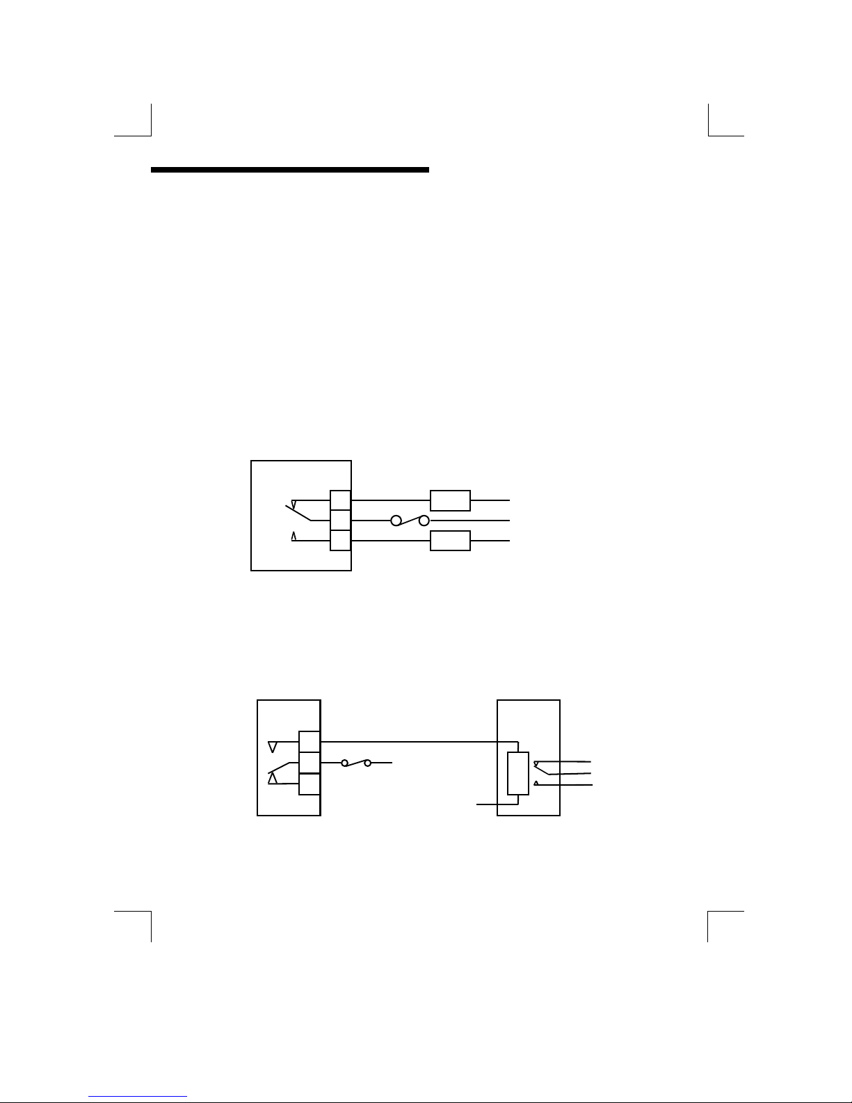
SET POINT RELAY CONNECTIONS
The relay contacts are connected to the terminals only and are electrically isolated
from the instrument itself. They must be connected in series with a 5 Amp
fuse.
MOD53
Load A
Neutral
Live
Neutral
Load B
5A
Figure 5 : Relay contact connection
A contact arc suppressor may be required to prevent excessive electrical noise,
depending upon the load. To switch more than 5 Amps will require a slave relay.
MOD53
Slave Relay
Neutral
Live
Figure 6 : Slave relay connection
Page 14
3 Installation – Panel Mount
13
For convenience, the power can be looped across from the supply connections.
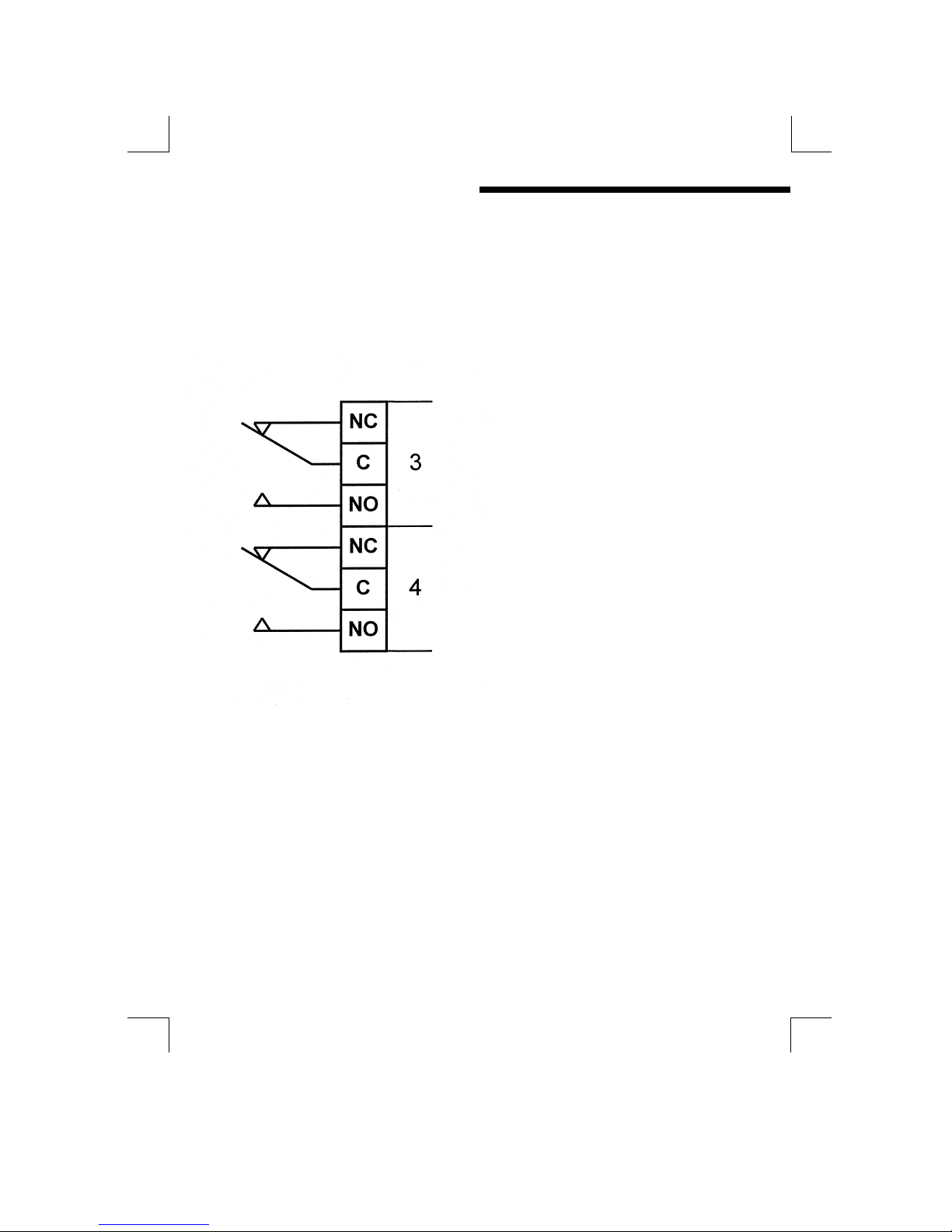
SET POINT RELAYS 3 & 4 CONNECTION
When fitted, the expansion port connector houses the additional relay output
terminals. NB The relay contacts are volt free and should be wired in series with a
supply and load { see Figure 5.}
NOTE :
NC = normally closed
NO = normally open
C = common
Figure 7 : Panel mount unit, Relays 3 & 4 wiring
Page 15
3 Installation – Panel Mount
14
BOTTOM CONNECTOR
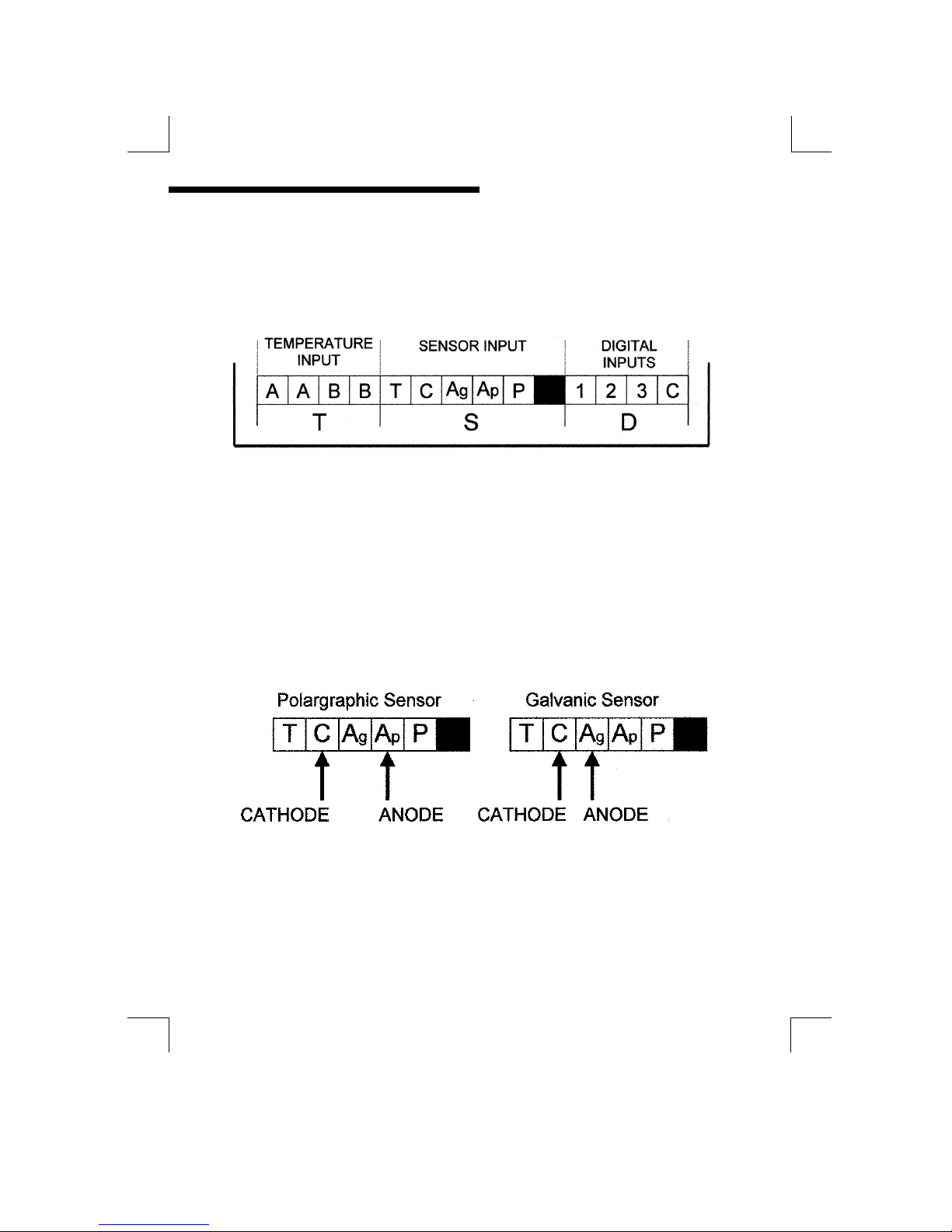
The bottom connector houses the sensor input and digital input connections. Two
separate connectors are used, separated by a blanking plug. A 9 way connector is
provided for the sensor input and a 4 way connector for the digital inputs.
Figure 8 : Panel mount unit, bottom connector wiring
SENSOR INPUT CONNECTIONS
The MOD53 has been designed with the flexibility to accept a wide variety of both
Galvanic and Polargraphic Dissolved Oxygen probes. Parameters such as
membrane correction, bias voltage and temperature sensor type can be easily
programmed into the instrument. It will be necessary to identify the sensor type
e.g. Galvanic or Polargraphic, and the temperature sensor type e.g. PT1000 or
thermistor.
Figure 9 : Sensor Connections
Page 16
3 Installation – Panel Mount
15
SENSOR TYPES
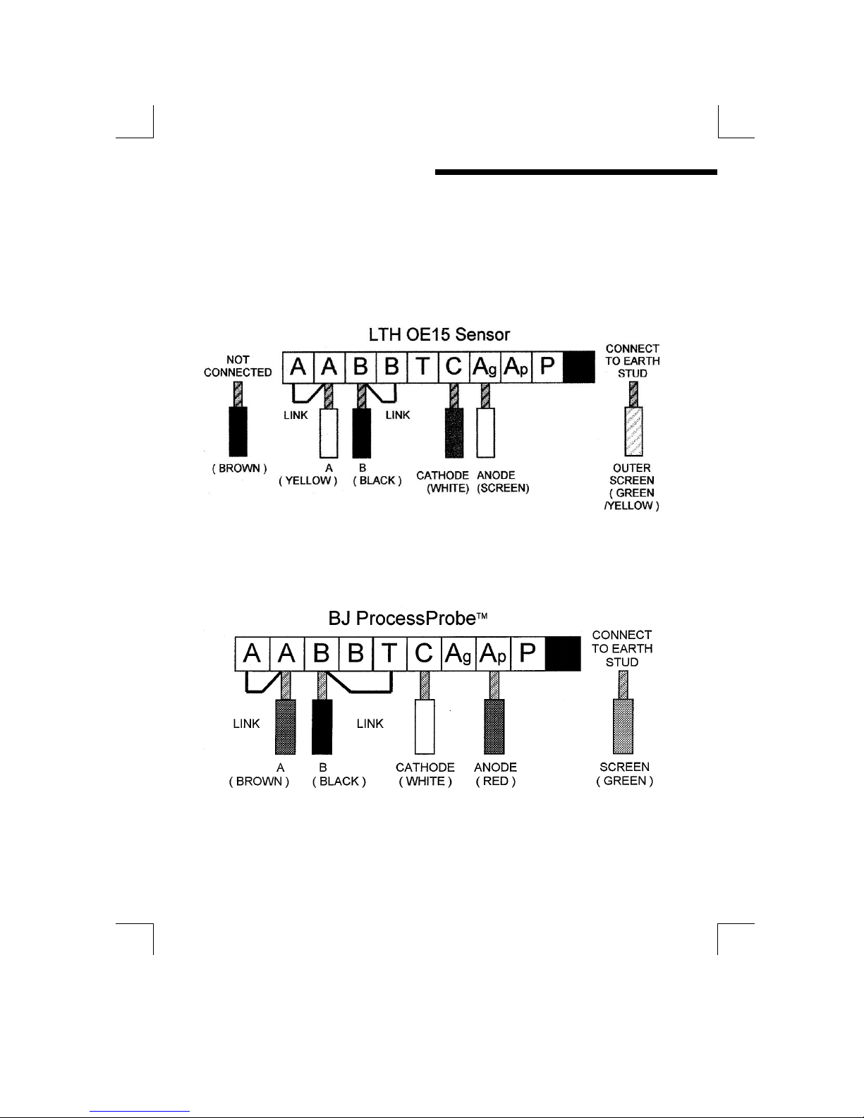
The following figures give the connection details of the most commonly used LTH
cable types. Do not use any other type of cable than those recommended by LTH
or the sensor manufacturer to extend the sensor / instrument distance.
Figure 10 : OE15 Cable
The outer screen/shield should be connected to the centre Earth Stud.
Figure 11 : ProcessProbe
TM
Cable
Page 17
3 Installation – Panel Mount
16
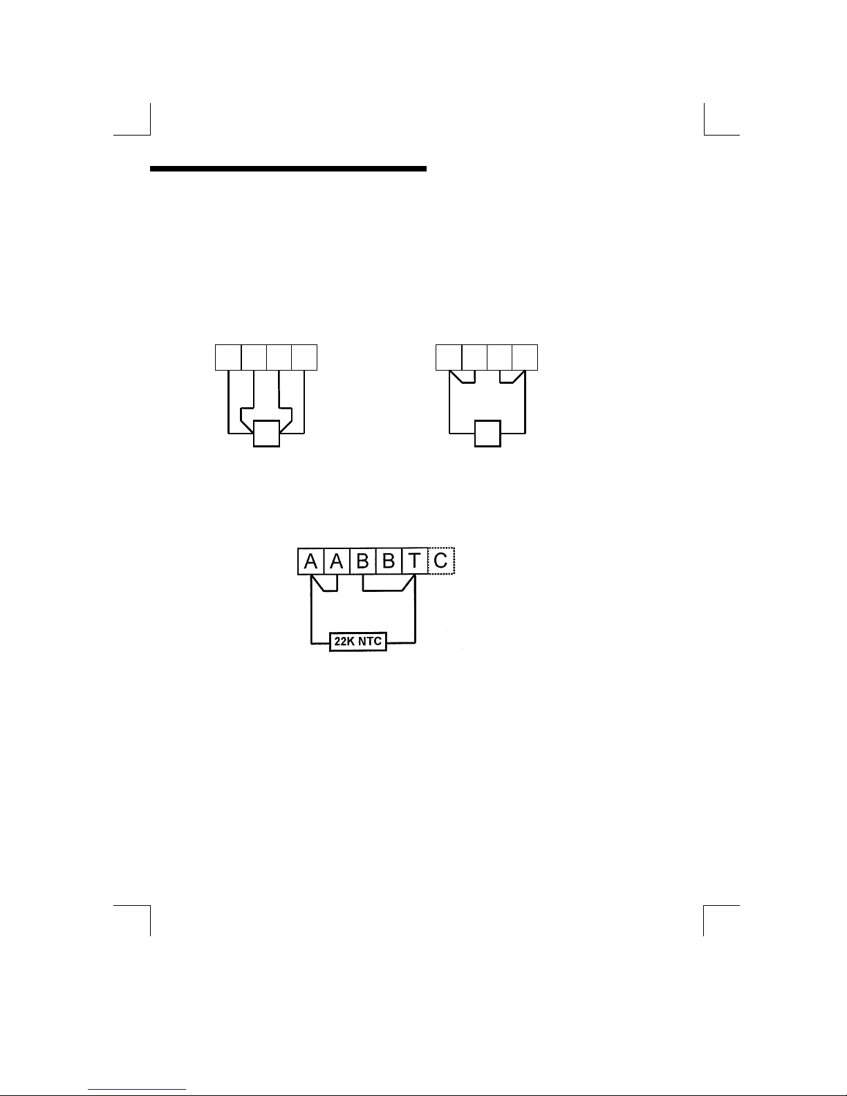
TEMPERATURE INPUT CONNECTIONS
The temperature input system is designed to measure resistive temperature
sensors. These can be configured as 2 or 4 wire sensors, although for the specified
accuracy it is necessary to use the 4 wire configuration for cable lengths over 5
metres.
Figure 12 : Standard RTD Temperature Connection
Figure 13 : ProcessProbe 22K Thermistor Connection
The MOD53 can be configured to accept a PT100, PT1000, 1K or 22K thermistor
temperature sensor. (see “Configuration” page)
A A B B A A B B
4 Wire RTD 2 Wire RTD
Page 18
3 Installation – Panel Mount
17
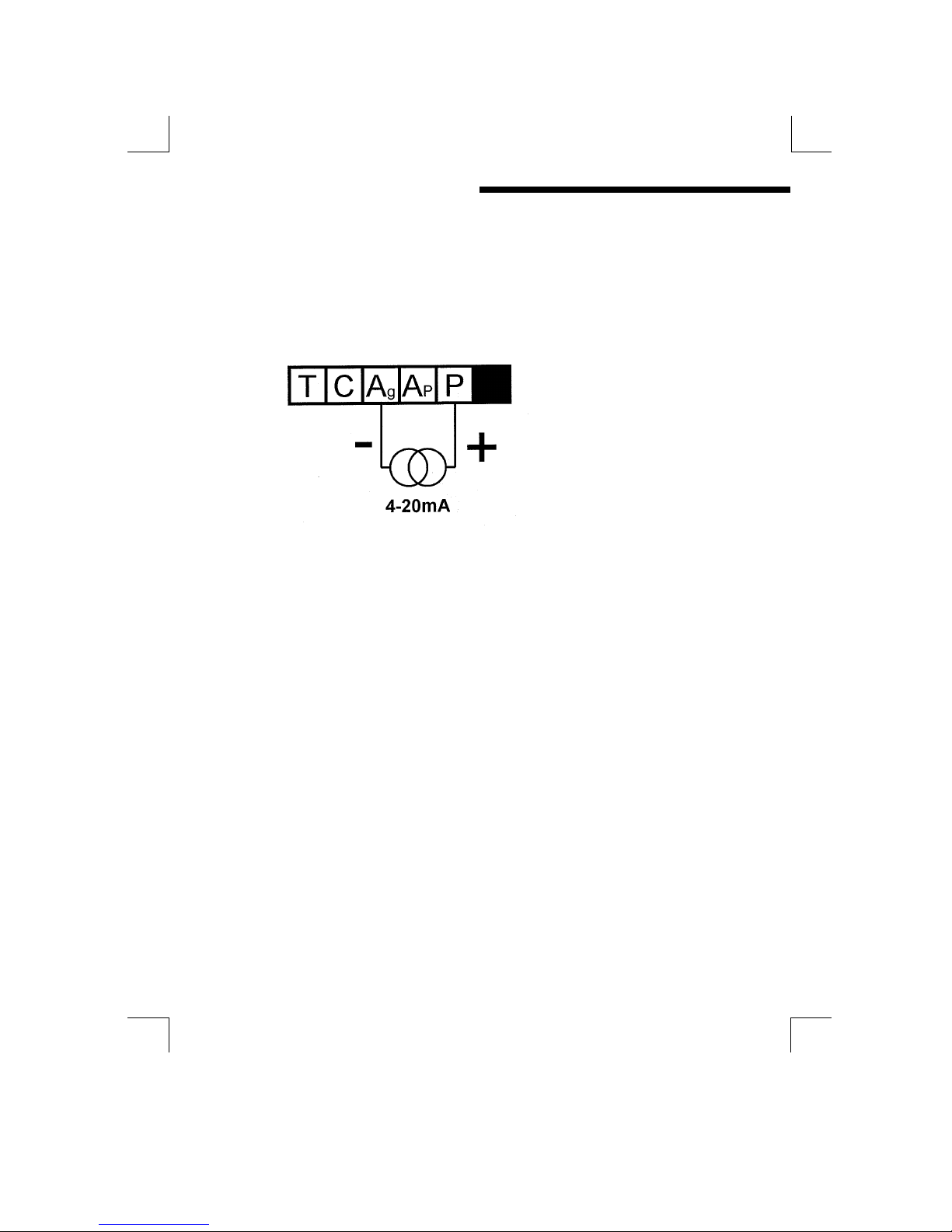
PRESSURE TRANSMITTER INPUT
The MOD53 can accept a 4-20mA input signal from a pressure transmitter. This
can be scaled within software and permits active pressure compensation of the
dissolved oxygen measurement. The signal can be either 24V loop powered, from
the MOD53, or externally powered from the transmitter. The mode of operation is
selected in the software set-up.
Figure 14 : Pressure Transmitter Connections
{ NB : The negative connection shares the same terminal as the Galvanic sensor
anode connection }
RC2 CLEANER CONNECTION
If the active pressure input is not being used, an RC2 rotary cleaner can be
powered from the “P” terminal. Connect the cleaner terminals through one of the
relay terminals* in the same polarity as for the active pressure input. Set the “P
Mode” function to “Auto” . Set the Pressure “Input” to “24V Loop”. Reset the
“P Mode” function to “Manual” . Configure the chosen relay (*) to “Cleaning” .
Page 19
3 Installation – Panel Mount
18
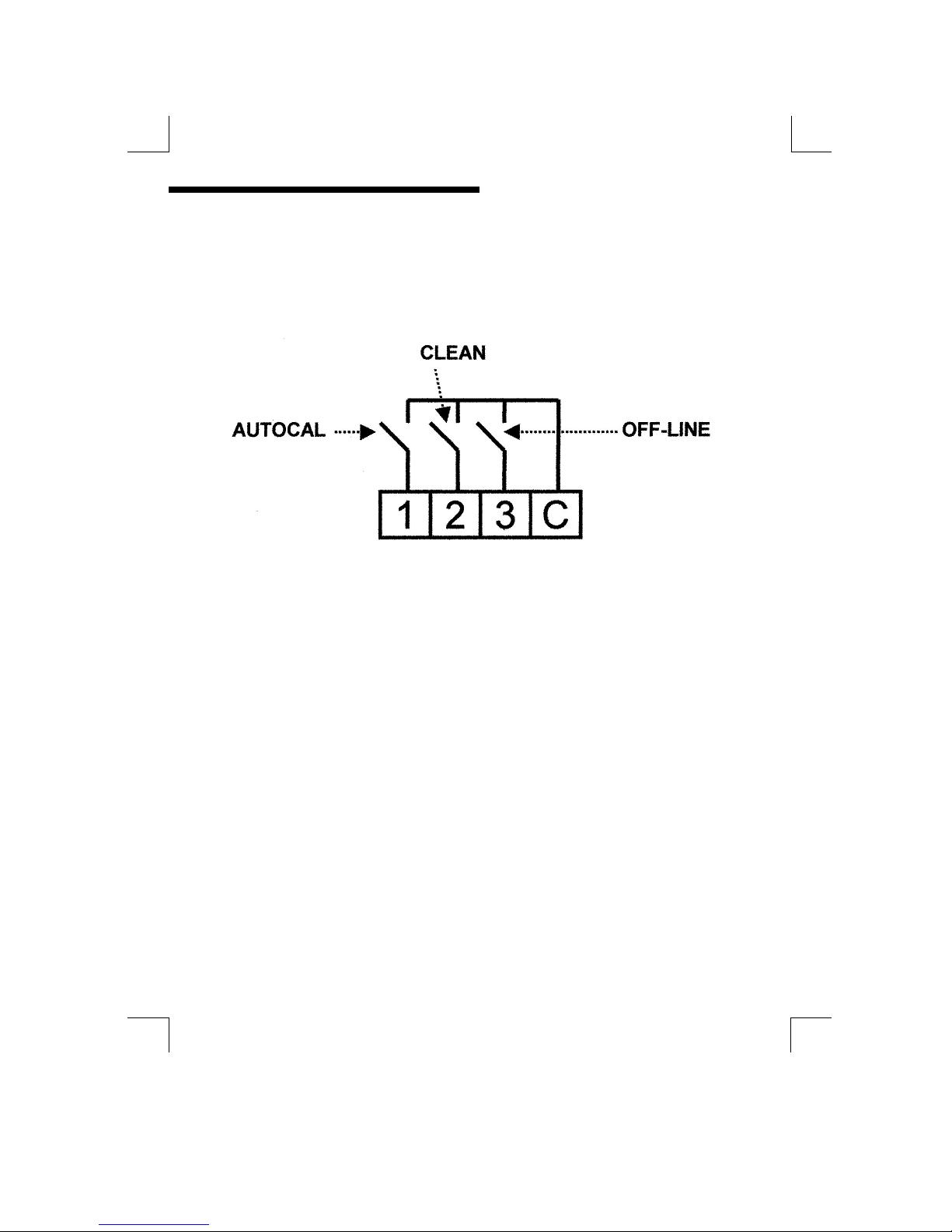
DIGITAL INPUTS
The digital inputs are used to externally initiate a clean cycle or take the unit OffLine. These inputs are intended to be switched using a volt free link , switch or
relay. Closing the contact will initiate the appropriate action.
Figure 15 : Digital Inputs
Page 20
4 Installation – Surface Mount
19
4 Installation – Surface Mount
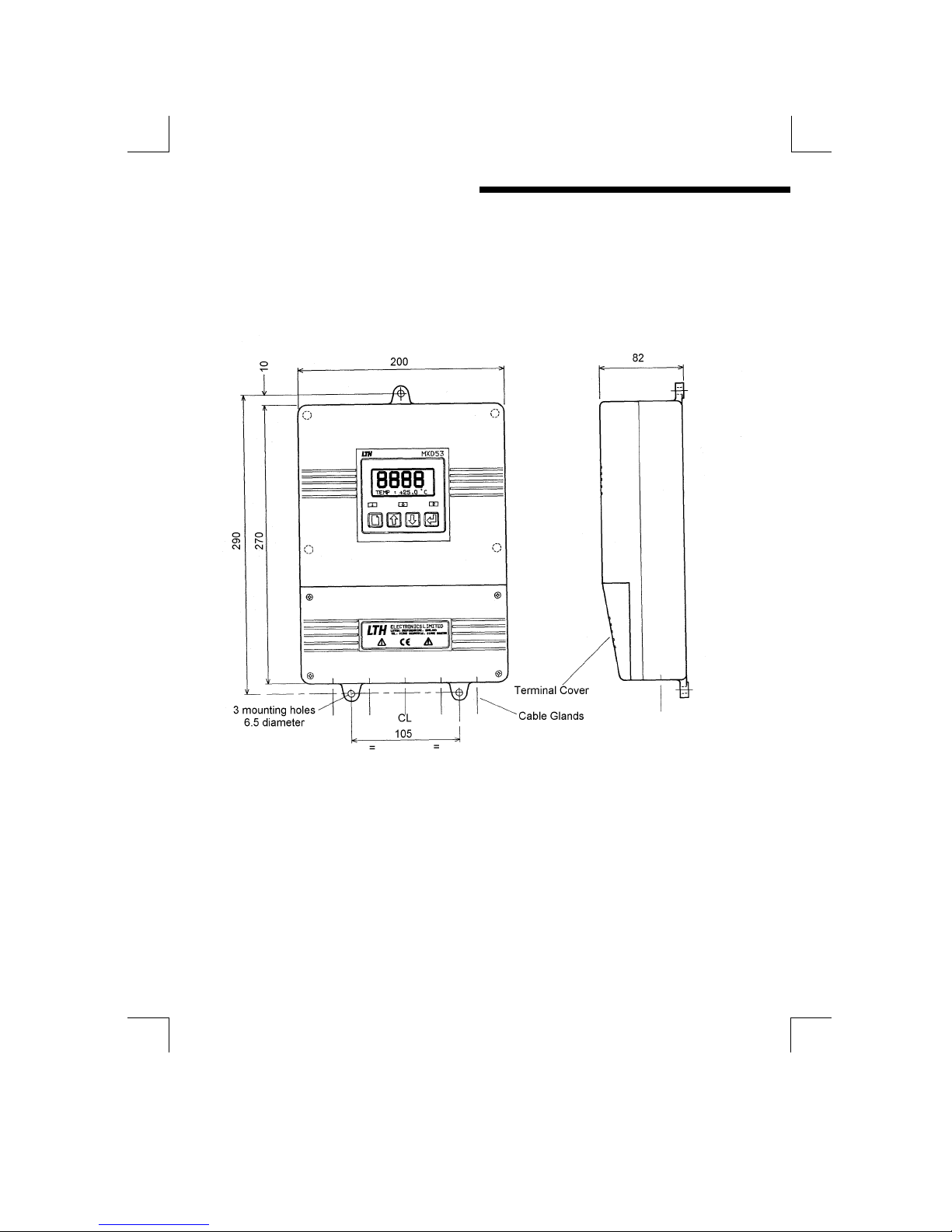
The surface mounting version is designed for fixing to a wall or other flat surface.
Three 6.5 mm diameter holes are provided for this purpose. Note that fasteners
are not provided.
Figure 16 : Overall dimensions surface mounting MOD53
♦ LTH recommend using No. 10 x 1¼ inch round head screws or similar for
mounting.
♦ Care must be taken when fitting the unit to uneven walls or surfaces. Do not
over stress the three mounting lugs.
♦ Over tightening the mounting screws could also break the lugs.
Page 21
4 Installation – Surface Mount
20
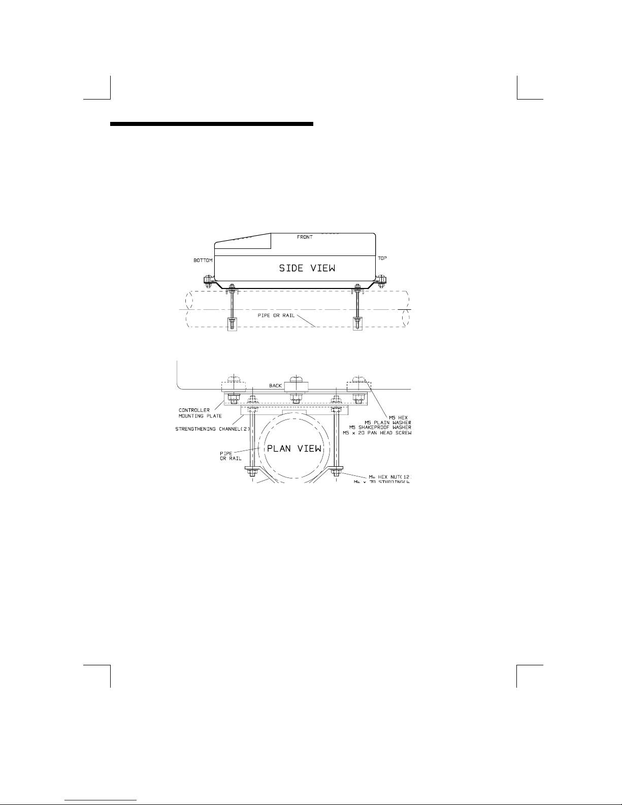
PIPE MOUNTING
The handrail & pipe mounting version is designed for fixing to a vertical or
horizontal handrail or pipe, of 25 - 60 mm outside diameter. The mounting kit
comprises one plate, two channels, two clamps, four studs, 3 x M5 nuts, 3 x M5
plain washers, 3 x M5 shake proof washers, 12 x M4 nuts and 12 x M4 shake proof
washers, as shown in the exploded view below.
Figure 17 : MOD53 handrail & pipe mounting brackets
• The brackets can be fitted either vertically or horizontally.
• Position the channels to the rear of the mounting plate and secure with 8 x M4
nuts and 8 x M4 shake proof washers as shown.
• Position the mounting plate assembly onto the pipe/handrail ensuring that the
single fixing hole for the controller is at the top.
• Secure the two pipe clamps with the 4 x M4 nuts and 4 x M4 shake proof
washers.
• Attach the controller to the mounting plate with the 3 sets of M5 fixings supplied.
Page 22
4 Installation – Surface Mount
21
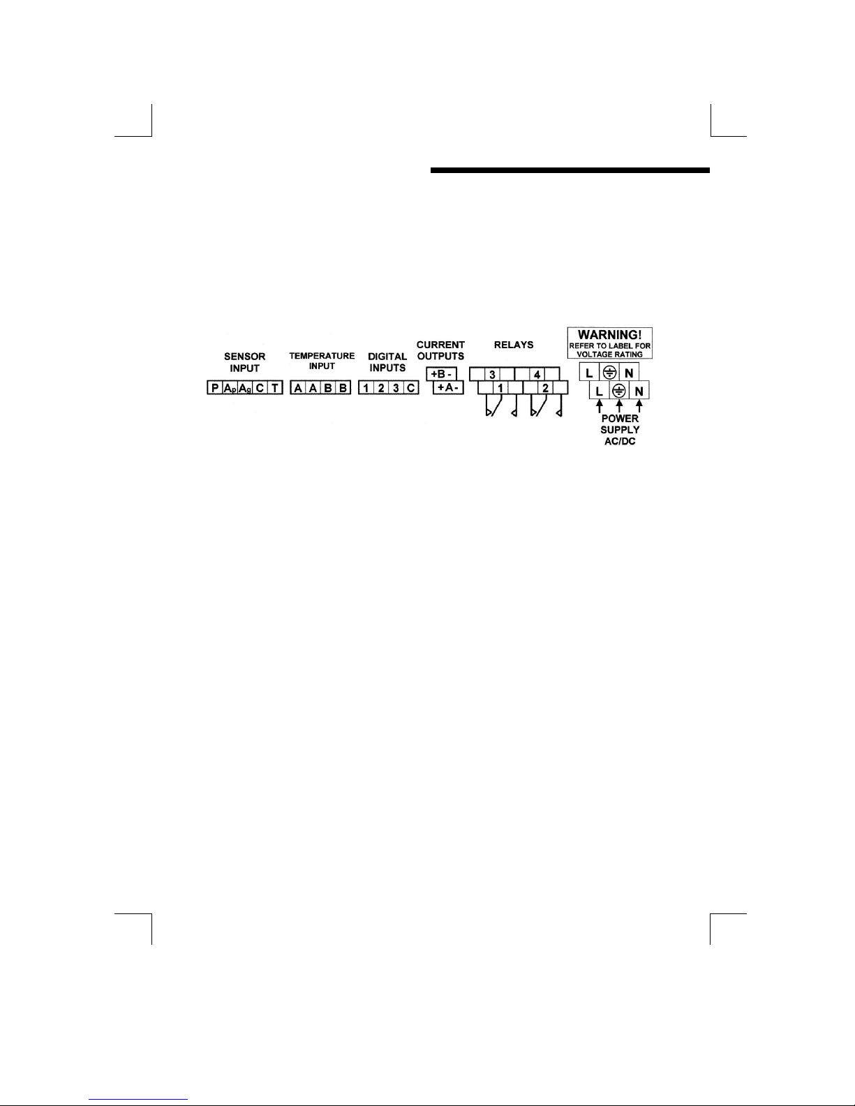
TERMINAL CONNECTIONS
Having ensured that the main power is isolated from the unit, remove the terminal
cover by releasing the screws at each corner. (The terminal cover is the small
cover at the bottom of the front panel. Once the cover has been removed the
following terminal arrangement should be visible. Some terminals may not be fitted
due to different supplied options.
Figure 18 : Surface mount unit, terminal connections
The cables should be fed through the cable glands. After each cable has been
attached, pull most of the cable slack back through the cable gland to prevent any
unwanted RF energy from being radiated inside the housing. Make sure not to
strain the cable within the instrument. Tighten the cable gland onto the cable so
that it grips sufficiently to seal and to prevent the cable from being pulled back
through the gland.
SUPPLY VOLTAGE CONNECTIONS
The MOD53 can be powered from either an AC or DC supply voltage. The unit
provides two terminals for each of the input connections (“Live” & “Neutral” for an
AC input, or + & - for a DC Input), plus an “Earth” terminal. This allows the supply to
be “daisy chained” to the relay contacts and/or other instruments. The instrument
uses a universal power supply that accepts a wide range of voltage and frequency
inputs. Refer to the label adjacent to the power supply terminals for the input
voltage limits. Exceeding these limits may damage the instrument.
Page 23
4 Installation – Surface Mount
22
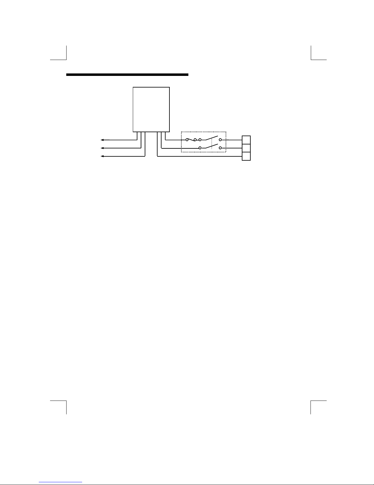
Figure 19 : Power supply “daisy chain” connection
The power supply should be taken from an isolated spur and fused to a maximum
of 3 Amps. If the relays require greater current, then a separate 5A fuse will be
required. The incoming Earth connection must be connected to the “Earth”
terminal.
CURRENT OUTPUT CONNECTIONS
The MOD53 can be supplied with up to 2 current outputs designated A and B. It is
shipped with links across the relevant current output pins if the option is fitted. If a
current output is required, remove the link and replace with a cable terminated by a
load resistance not exceeding 1000Ω. For best noise immunity use a screened
twisted pair cable, with the screen connected to Earth at one end. Use a sufficiently
large cable to avoid a high resistance in the overall current loop. When either of
the outputs is open circuit, in a dual output unit, the other will indicate a fault
by transmitting a 2mA signal. This will be accompanied by a flashing error
message on the Display ( E41 ).
MOD53
OUT IN
3A
L
N
E
Page 24
4 Installation – Surface Mount
23
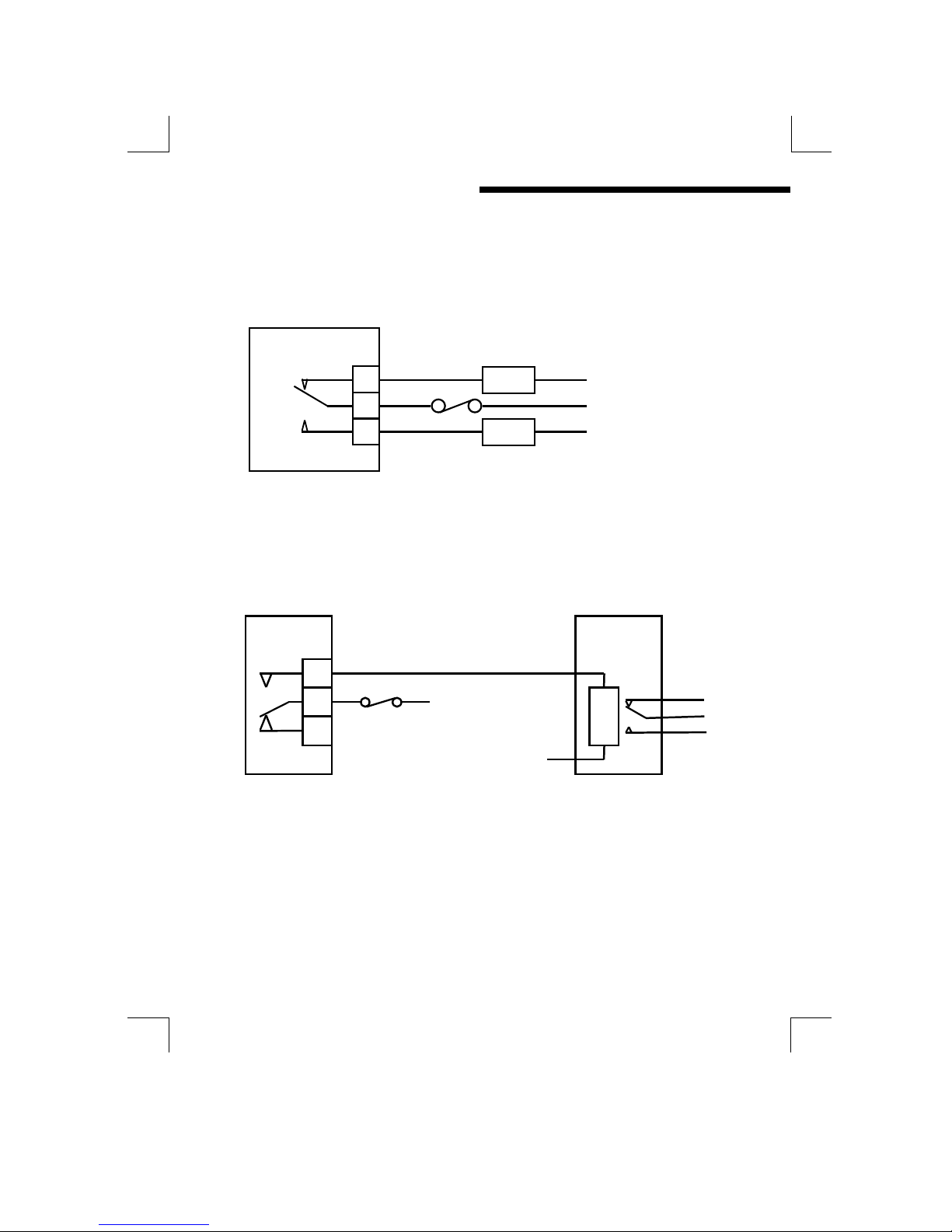
RELAY CONNECTIONS
The relay contacts are connected to the terminals only and are electrically isolated
from the instrument itself. They must be connected in series with a 5 Amp fuse.
MOD53
Load A
Neutral
Live
Neutral
Load B
5A
Figure 20 : Relay contact connection
A contact arc suppressor may be required to prevent excessive electrical noise,
depending upon the load. To switch more than 5 Amps will require a slave relay.
MOD53
Slave Relay
Neutral
Live
Figure 21 : Slave relay connection
For convenience, the power can be looped across from the supply connections.
Page 25
4 Installation – Surface Mount
24
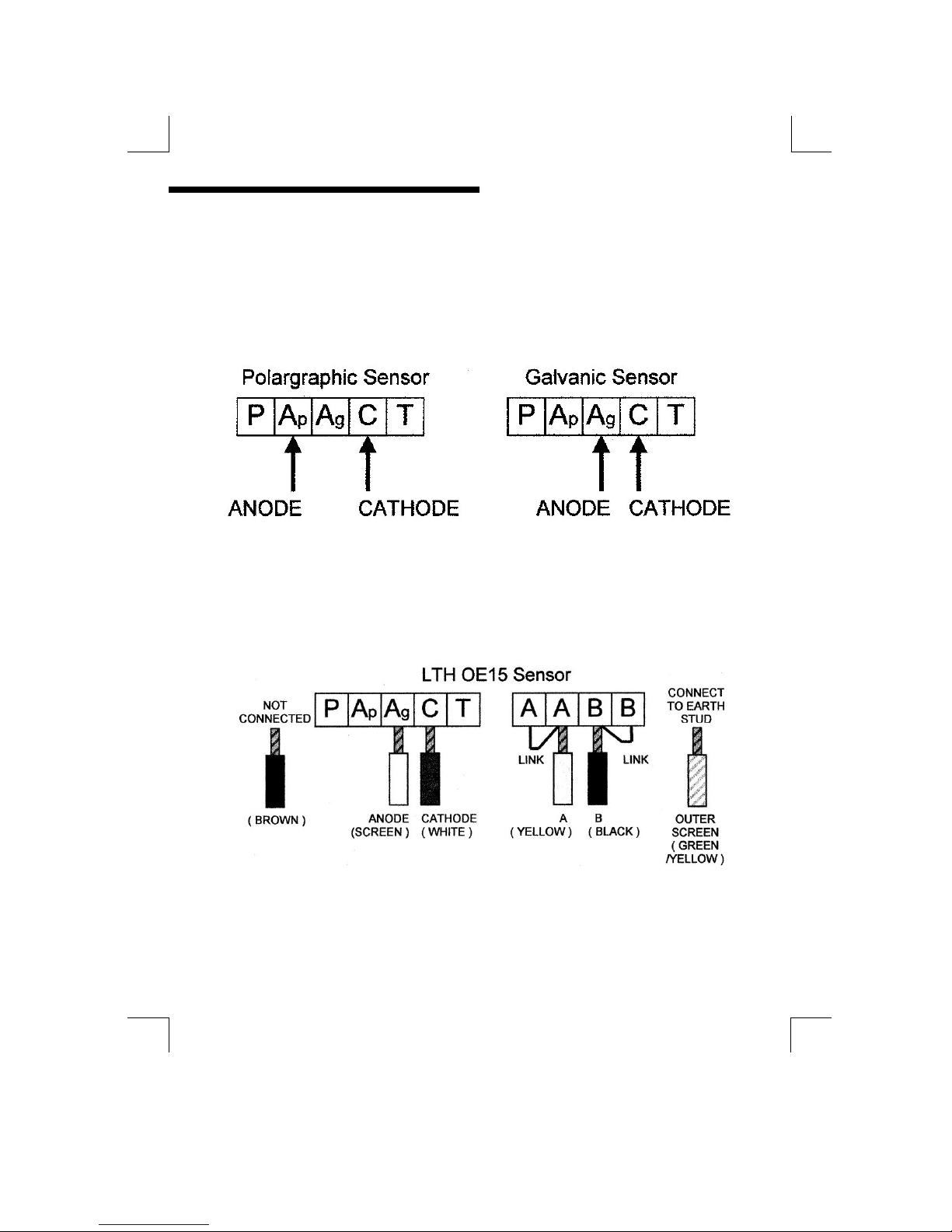
SENSOR INPUT CONNECTIONS
The MOD53 has been designed to accept a wide variety of both Galvanic and
Polargraphic Dissolved Oxygen probes. Parameters such as membrane
correction, bias voltage and temperature sensor type can be easily programmed
into the instrument. It will be necessary to identify the sensor type e.g. Galvanic or
Polargraphic, and the temperature sensor type e.g. PT1000 or thermistor.
Figure 22 : Sensor Connections
SENSOR TYPES
The following figures give the connection details of the most commonly used LTH
cable types. Do not use any other type of cable than those recommended by LTH
or the sensor manufacturer to extend the sensor / instrument distance.
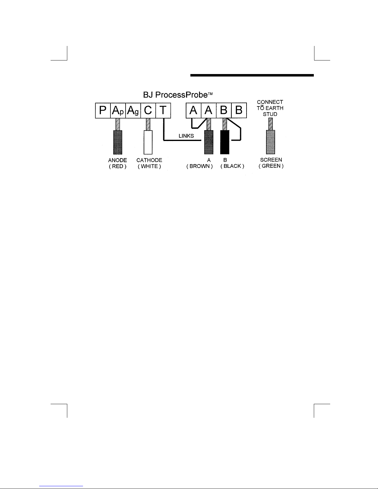
The outer screen/shield should be connected to the centre Earth Stud.
Figure 23 : OE15 Cable
Page 26
4 Installation – Surface Mount
25
Figure 24 : ProcessProbe
TM
Cable
Page 27
4 Installation – Surface Mount
26
TEMPERATURE INPUT CONNECTIONS
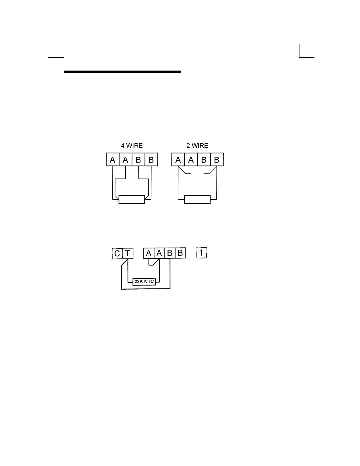
The temperature input system is designed to measure resistive temperature
sensors. These can be configured as 2 or 4 wire sensors, although for the
specified accuracy it is necessary to use the 4 wire configuration for cable lengths
over 5 metres.
Figure 25 : Standard RTD Temperature Connection
Figure 26 : ProcessProbe 22K Thermistor Connection
The MOD53 can be configured to accept a PT100, PT1000, 1K or 22K thermistor
temperature sensor. (see “Configuration” page).
Page 28
4 Installation – Surface Mount
27
PRESSURE TRANSMITTER INPUT
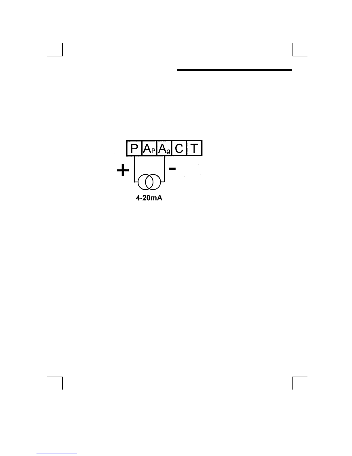
The MOD53 can accept a 4-20mA input signal from a pressure transmitter. This
can be scaled within software and permits active pressure compensation of the
dissolved oxygen measurement. The signal can be either 24V loop powered, from
the MOD53, or externally powered from the transmitter. The mode of operation is
selected in the software set-up.
Figure 27 : Pressure Transmitter Connections
{ NB : The negative connection shares the same terminal as the Galvanic sensor
anode connection }
RC2 CLEANER CONNECTION
If the active pressure input is not being used, an RC2 rotary cleaner can be
powered from the “P” terminal. Connect the cleaner terminals through one of the
relay terminals* in the same polarity as for the active pressure input. Set the “P
Mode” function to “Auto” . Set the Pressure “Input” to “24V Loop” . Reset the
“P Mode” function to “Manual”. Configure the chosen relay (*) to “Cleaning” .
Page 29
4 Installation – Surface Mount
28
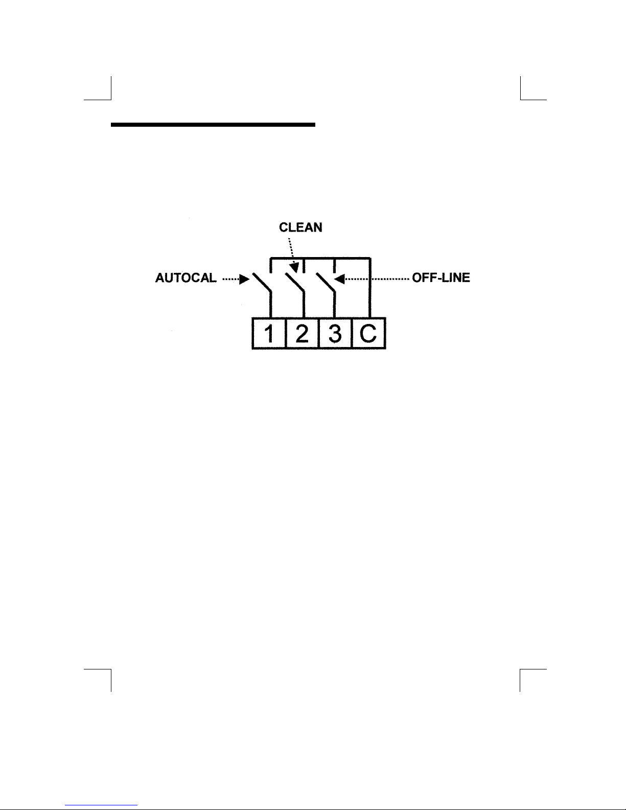
DIGITAL INPUTS
The digital inputs are used to externally initiate a clean cycle or take the unit OffLine. These inputs are intended to be switched using a volt free link , switch or
relay. Closing the contact will initiate the appropriate action.
Figure 28 : Digital Inputs
Page 30
5 User Interface
29
5 User Interface
CAUTION!
BEFORE PROCEEDING, ENSURE THAT THE INSTALLATION
INSTRUCTIONS HAVE BEEN FOLLOWED CORRECTLY. FAILURE TO DO SO
MAY RESULT IN AN ELECTRICALLY HAZARDOUS INSTALLATION, OR
DEGRADE INSTRUMENT PERFORMANCE.
When shipped the MOD53 is configured to the default % saturation set-up. In this
state, the instrument can perform all of the necessary function for a basic dissolved
oxygen monitoring instrument.
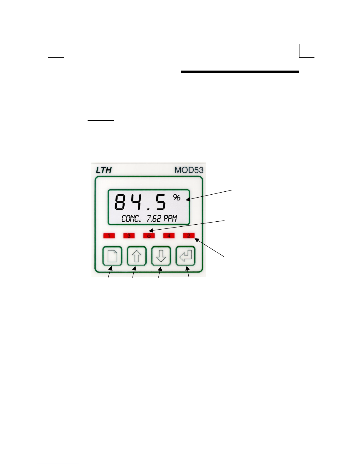
THE FRONT PANEL
The MOD53 uses a versatile dot matrix character LCD to display all of the settings
and readings. The seven segment digits at the top of the display indicate the
primary measured value during normal operation. The six character display to the
right of these indicates the units of measurement when a value is being displayed.
The sixteen characters on the bottom of the display are used to indicate secondary
readings or states, and to display scrolling error messages.
LIQUID
CRYSTAL
DISPLAY
OFFLINE
STATUS LED
UP TO 4
STATUS
LEDS FOR
SET POINTS
PAGE UP DOWN ENTER
PROGRAMMING BUTTONS
Page 31

5 User Interface
30
Along with the LCD display, the front panel also incorporates five LEDs. The four
outer LEDs (labelled 1,2,3 & 4) indicate the set point status, i.e. when the LED is
illuminated the indicated relay is active. The centre LED indicates when the unit is
“Off-Line”. Note: Not all relay channels may be fitted.
THE MENU SYSTEM
When the instrument is switched on, it will default to the main display menu. The
user interface to the MOD53 is arranged as a menu structure, a summary of which
is printed as a fold out sheet at the back of this guide. Movement around this
menu structure is achieved using the “PAGE”, “UP” and “DOWN” keys at the
bottom of the front panel. The functions within each menu are explained in detail
in the following sections of this guide.
ERROR MESSAGES
If the internal diagnostics have detected an error condition, the appropriate error
message will flash on the bottom row of the display. Pressing the “ENTER” key
when an error message is flashing will scroll a more detailed description of the
error along the bottom line. Pressing “ENTER” again will return the unit to the
flashing display. The error messages can be disabled within the “Configuration”
menu. If the error messages are disabled, the display will flash a bell symbol on
the far right of the bottom row when an error is detected. It is possible to configure
Relay 4 (if fitted) as an error relay to provide external indication of error conditions.
ACCESS ENTRY
To protect the instrument setup from unauthorised or accidental tampering, an
access code must be entered. The “Access Entry” menu will appear when the
“PAGE” key is first pressed from the main display menu. A character on the upper
right of the display will indicate whether access is permitted. The character will be
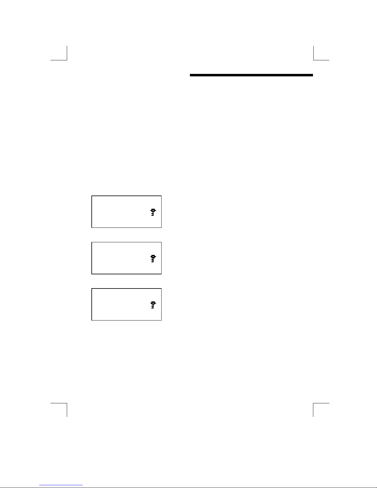
a key for permitted access and a padlock for denied access. By default the access
code will appear as 0000, however to unlock the instrument the correct code will
need to be entered.
Page 32
5 User Interface
31
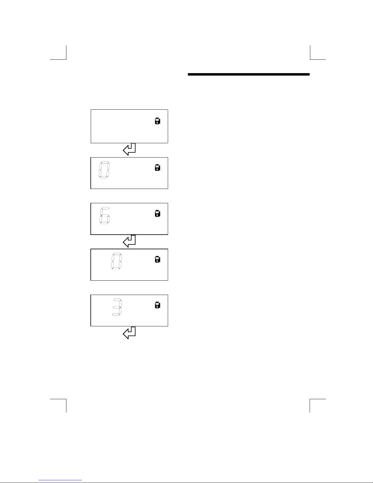
Enter the access code as follows. { Note : “Outlined” text represents flashing
digits/characters on the display }.
0000
00000000
0000
Access Code ?
Press “ENTER” to begin editing the access
code.
000
000000
000
Access Code ?
ØØØØ ××××
Use the “UP” and “DOWN” keys to change the
first digit
0
00
000
0000
00
Access Code ?
Press “ENTER” to select the next digit
6
66
6 00
0000
00
Access Code ?
ØØØØ ××××
Use the “UP” and “DOWN” keys to change the
second digit
6
66
6 00
0000
00
Access Code ?
Press “ENTER” to select the next digit
Continued on next page .......
Page 33
5 User Interface
32
63
6363
63 0
00
0
Access Code ?
ØØØØ ××××
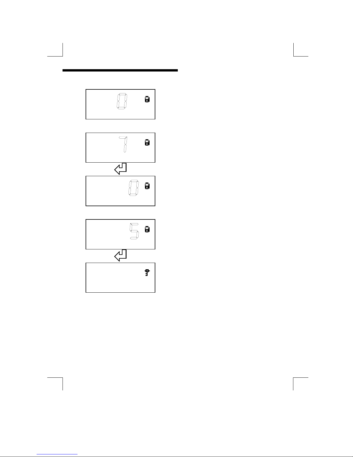
Use the “UP” and “DOWN” keys to change the
third digit
63
6363
63 0
00
0
Access Code ?
Press “ENTER” to select the next digit
637
637637
637
Access Code ?
ØØØØ ××××
Use the “UP” and “DOWN” keys to change the
last digit
63
6363
637
77
7
Access Code ?
Press “ENTER” to store the new code
6375
63756375
6375
Access Code ?
If the new code is correct the Padlock symbol
will now change to a Key symbol.
{ Note 6375 is only an example of an access code, the correct code will need to be
entered to unlock the instrument.}
The default access codes are 0001 for level one and 0002 for level 2.
When the key symbol is displayed the operator may then move through the menu
structure using the “PAGE”, “UP” and “DOWN” keys. Pressing the “PAGE” key will
advance the unit on to the next menu header, using the “UP” and “DOWN” keys
the operator can then select the items within that menu.
Page 34
5 User Interface
33
Pressing the “PAGE” key from within a menu will return the unit to the menu’s
header, subsequent presses of the “PAGE” key will advance to the next menu.
When the last menu is reached the unit will return to the normal display mode.
Using the “PAGE” and “ENTER” keys simultaneously will allow the unit to move
backwards through the menus.
N.B. When in the menu structure, if none of the buttons are pressed within 2
minutes, the unit will timeout and return to the main display. The Access
Code display will be reset to 0000 30 seconds after returning to the main
display.
There are two levels of access to the menu structure (refer to the menu structure
printed inside the back cover). The first level allows access to the basic setup
operations. The more complex level two menus will only appear when the level
two access code has been entered. Once the access code has been entered
correctly the operator can use the “UP” and “DOWN” keys to select and modify the
access codes.
000
000000
0000
00
0
Access Code ?
Access Code Entry
ØØØØ ××××
0001
00010001
0001
Edit Level 1
Level 1 Code Edit. Press “ENTER” to edit.
(Available when level 1 code has been entered)
ØØØØ ××××
0002
00020002
0002
Edit Level 2
Level 2 Code Edit. Press “ENTER” to edit.
(Available when level 2 code has been entered)
ØØØØ ××××
Page 35
5 User Interface
34
UNIT CONFIGURATION
Editing of discrete values (such as Set Point Level or Fixed Temperature Input) is
performed in the same way as described previously for the access code entry.
Changing states (such as Units or Set Point Mode) is achieved in a similar fashion.
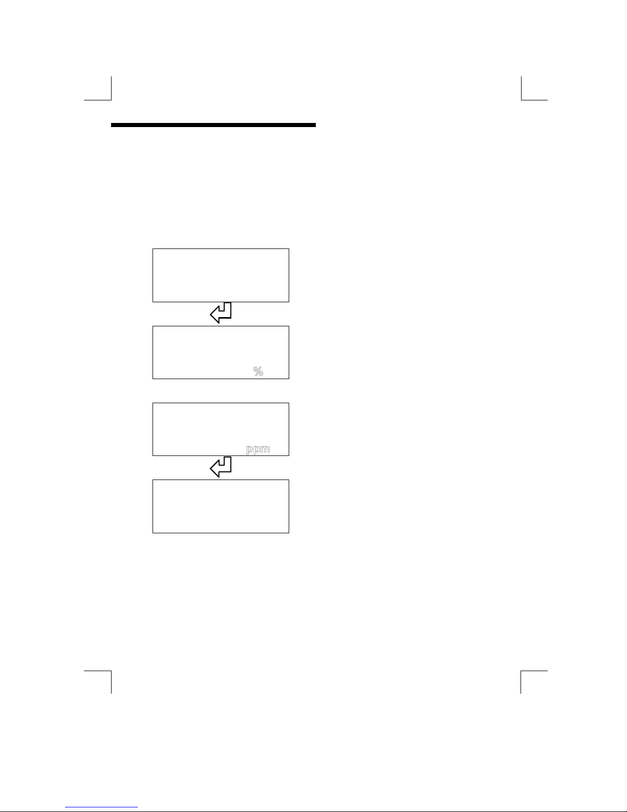
E.g. Using the “Units” menu function (in the “Parameters” menu). Press the
“ENTER” key to start the text flashing. Press the “UP” and “DOWN” keys to cycle
through the displayed states, then press “ENTER” to select the required state.
Units : %
Press “ENTER” to start the units
flashing
Units :
ØØØØ ××××
Use the “UP” and “DOWN” keys to
cycle through the flashing options
Units :
Press “ENTER” to select the
flashing option
Units : ppm
Page 36
5 User Interface
35
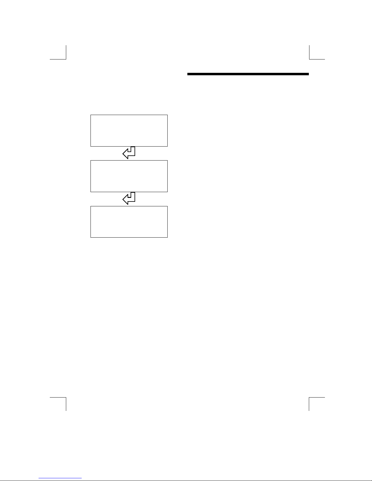
For functions such as Calibration and Restoring Setup, press the ”ENTER” key to
initiate the function, the system will then ask for confirmation. Press “ENTER” to
continue or “UP” or ”DOWN” to cancel the function. e.g.
Restore Setup B
Select the required function and press the
“ENTER” key.
Are You Sure ?
To continue press the “ENTER” key again
To abort the “Restore”, press any other
key
Restoring
When the setup has been restored, the
system will return to the main display.
The following sections of this guide describe in more detail each of the menus and
their functions.
Page 37

5 User Interface
36
This page intentionally blank
Page 38

6 Main Display
37
6 Main Display
The normal mode of operation is to display the sensor reading on the top row and
a secondary reading on the bottom row. Using the “UP” and “DOWN” keys the
user can cycle through the secondary parameters (those available depend upon
the instrument options and configuration).
10.00
10.0010.00
10.00
ppm
Sat. : 100.0%
Sensor Concentration + Saturation
(When Display units are Concentration)
ØØØØ ××××
100.0
100.0100.0
100.0
%
Conc. : 15.53 ppm
Sensor Saturation + Concentration
(When Display units are Saturation)
ØØØØ ××××
Any combination of Sensor operating units can be displayed here in the same
format as the two examples above, but are excluded here for brevity (a total of
20 combinations are possible). The main display will always be the units
selected in the Parameters Menu (%Sat, ppm, mBar, mm Hg, nA/uA). The
secondary display can be one of the remaining four units or as follows below.
ØØØØ ××××
60.0
60.0 60.0
60.0
%
SP1 : 10.0%
Sensor + Set Point 1
(When SP1 Trigger = High or Low)
ØØØØ ××××
60.0
60.0 60.0
60.0
%
SP1H : 4.00%
Sensor + Set Point 1 High
(When SP1 Trigger = Band or Latch)
ØØØØ ××××
Continued on next page .........
Page 39

6 Main Display
38
ØØØØ ××××
60.0
60.0 60.0
60.0
%
SP1L : 2.00%
Sensor + Set Point 1 Low
(When SP1 Trigger = Band or Latch)
ØØØØ ××××
Set Points 2 & 3 are displayed here in the same format as for Set Point 1 but
are excluded here for brevity. A Set Point will not be displayed if has been
configured to “Cleaning” operation
ØØØØ ××××
60.0
60.0 60.0
60.0
%
Temp : +72.5°C
Sensor + Temperature Input
(When Compensation = Auto)
ØØØØ ××××
60.0
60.0 60.0
60.0
%
Man IP : +25.0°C
Sensor + Fixed Temperature
(When Compensation = Manual)
ØØØØ ××××
60.0
60.0 60.0
60.0
%
Salin.: 12.3ppt
Sensor + Fixed Salinity Setting
ØØØØ ××××
60.0
60.0 60.0
60.0
%
Press. : 2.35Atm
Sensor + Pressure Input
(or fixed setting if compensation = Manual)
ØØØØ ××××
Continued on Next Page ……….
Page 40

6 Main Display
39
ØØØØ ××××
60.0
60.060.0
60.0
%
Output A : 12.76mA
Sensor + Current Output A (if fitted)
ØØØØ ××××
60.0
60.060.0
60.0
%
Output B : 12.76mA
Sensor + Current Output B (if fitted)
ØØØØ ××××
60.0
60.060.0
60.0
%
Zero Cal
Zero (0% Saturation) Calibration
(Available when access parameter set in
“Calibration” menu).
ØØØØ ××××
60.0
60.060.0
60.0
%
Span Cal.
Span (100% Saturation) Calibration
(Available when access parameter is set in
the “Calibration” menu).
ØØØØ ××××
1.00
1.00 1.00
1.00
Atm
Calib Pressure
When “Span Calibration” is complete the
calibration pressure is displayed. (The
Calibration Pressure can be set manually in
the “Calibration” menu).
Selecting the parameter and pressing the “ENTER” key (provided that no error
messages are present) will set the default secondary parameter. This is the
default parameter that is displayed on the bottom line, when the unit is switched
on, or as a result of returning to the normal display mode.
Page 41

6 Main Display
40
This page intentionally blank
Page 42
7 Parameters
41
7 Parameters
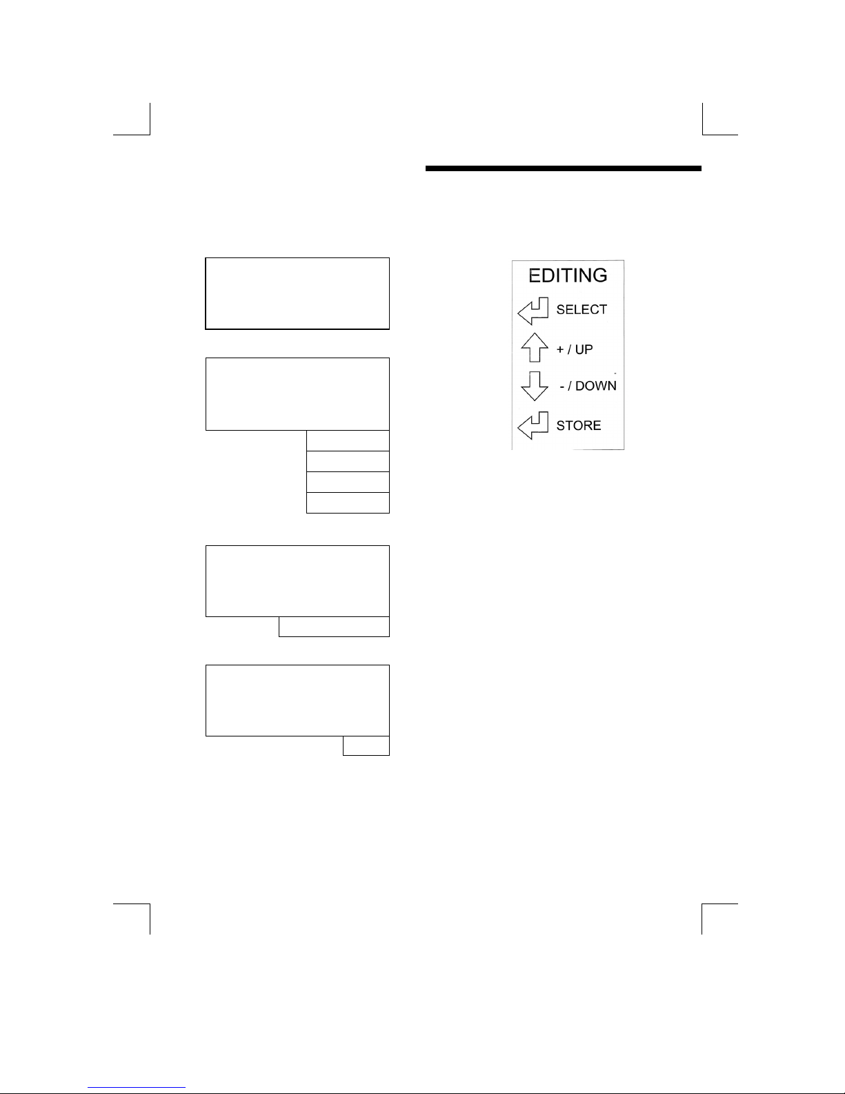
The “Parameters” menu contains the basic configurations for the sensor inputs
Parameters
Parameters
Menu Header
ØØØØ ××××
Units : % Sat
ppm
pO2
mm Hg
Current
Display Units
ØØØØ ××××
Probe : Galvanic
Polargraphic
Sensor Type
ØØØØ ××××
Temp Units : °C
°F
Temperature Display Units
ØØØØ ××××
Continued on next page .........
Page 43

7 Parameters
42
ØØØØ ××××
TC Mode : Auto
Manual
Temperature Compensation Mode. Only
present if temperature sensor (T Input) is
enabled under “Configuration” menu page.
(Otherwise defaults to “Manual”)
ØØØØ ××××
+25.0
+25.0 +25.0
+25.0
°C
Manual
Temperature input for manual
compensation. Only present when
temperature compensation is set to Manual.
ØØØØ ××××
19.0
19.019.0
19.0
ppt
Input Salinity
Salinity level set
ØØØØ ××××
P Comp : Manual
Auto
Pressure Compensation Mode :
Auto : From the active 4-20mA input
Manual : From user set Pressure Level
ØØØØ ××××
Continued on next page .........
Page 44
7 Parameters
43
P Units: Atm
Bar
kPa
m H2O
p
si
mm Hg
Pressure Display Units. Available when the
pressure compensation is set to “Manual”
ØØØØ ××××
1.0
1.01.0
1.0
Bar
Input Pressure
Fixed pressure level when
compensation is manual
ØØØØ ××××
Simulate Input
Press “ENTER” to Select the Input
Simulation Mode
1.0
1.01.0
1.0
ppm
Simulate : 12.00mA
Simulate sensor input. Use the “Up”
and “Down” keys to scan through the
input range to test the Set Point
Relays and Current Outputs
UNITS
The MOD53 primary display can be setup to display in % (saturation), ppm
(concentration), pO2 (partial pressure of Oxygen) or input current. This is achieved
by simply setting the appropriate units. The relationship between these three
parameters is determined by several factors including temperature, pressure and
the salinity of the solution being measured. (See Appendix A).
Page 45

7 Parameters
44
SENSOR TYPE
The MOD53 can scale its input readings to operate with either a Galvanic
(Mackereth) or Polargraphic (Clark) sensor. This enables the instrument to be used
with a variety of different manufacturers’ sensors. Both types of sensor provide a
current output, but Polargraphic sensors require a polarising voltage to be applied
across the Anode and Cathode. Other parameters will need to be set such as the
bias voltage, membrane correction and temperature sensor type. These settings
will need to be obtained from the manufacturer of the sensor
TEMPERATURE INPUT
Temperature has a significant effect on the output from the sensor, and it is
therefore necessary to compensate for the variations in the liquid and the sensor.
The MOD53 provides the facility to measure and automatically compensate for
these temperature variations, or alternatively, if no temperature sensing is
available, the user can select manually the temperature at which the unit
compensates. It is recommended that unless a stable measurement temperature
is achievable, the automatic compensation be used.
The operator can apply automatic or manual temperature compensation to the
dissolved oxygen measurement by selecting the mode of operation in the “T.
Comp.” menu item within the “Parameters” menu. For automatic compensation,
the correct temperature sensor must be selected in the Configuration menu. When
the manual mode of operation is selected the user can enter the fixed process
temperature under the Fixed Temp. Menu. { Note. When the automatic mode is
selected the Fixed Temp. menu will not be present }.
NOTE : If a Temperature sensor fault is detected, the unit defaults to the “Fixed
Temp” setting for compensation purposes, and displays an error condition.
The operator can choose to display all temperatures in °C or °F by modifying the
“T. Units” parameter. All temperature related displays will use the units selected
in this menu. N.B. The system will normally convert all temperature related
variables when the units are changed, however it may be wise for the operator to
ensure that changing the units has not altered the set points or current outputs.
SALINITY
The salinity of the solution has a significant effect when converting % Saturation to
concentration. The user can compensate for this by setting the “Input Salinity”
parameter to the correct level. (Entered in ppt, parts per thousand).
Page 46

7 Parameters
45
PRESSURE COMPENSATION
The MOD53 can accept a 4-20 mA input from a pressure transmitter to permit
automatic compensation for variations in the pressure. If it is available, set the “P
Comp” parameter to “Auto”. If not, set the “P Comp” parameter to “Manual” and
set the measurement pressure at the “Input Pressure” parameter. The units for
pressure display can be set to either “Bar”, “Atm”, “psi”, “kPa”, “m H
2
O” or “mm
Hg” at the “P Units” parameter. Variations of pressure can have a significant on
the sensor output..
SIMULATED INPUT
The facility exists within the MOD53 to simulate the input sensor levels to test the
set point and current output operation. This function allows the user to cycle up
and down through the sensor range using the “UP” and “DOWN” keys and display
the current output level, with the relays responding accordingly.
To select the Simulate menu item from the Parameters menu, press the “ENTER”
key. The unit will now display the simulation menu. Pressing the “UP” and
“DOWN” keys will cycle the displayed value between its minimum and maximum
levels in steps of 1%. The relays and current output will respond as if the displayed
value were an actual input, thus allowing the user to debug the set point and
current output configurations.
Page 47

7 Parameters
46
This page intentionally blank
Page 48
8 Set Points
47
8 Set Points
The Set Point configuration is separated into two menus, the first “Set Points 1&2”
and the second “Set Points 3&4” (if fitted). The menu structures for Set points 1,2
& 3 are identical, and provide a high level of flexibility in the configuration of the
relay outputs.
Set Points 1&2
Set Points
Menu Header
ØØØØ ××××
SP1 : Disabled
Sensor IP
Temp IP
Cleaning
Set Point Source
Control. When
cleaning is
selected the
following menu
items will be
replaced by the
”Cleaning”
menus
ØØØØ ××××
SP1 Trig : High
Low
Band
Latch
Set Point Trigger
ØØØØ ××××
4.00
4.00 4.00
4.00
Set Point 1
Set Point Level
(When trigger is “High” or “Low”)
ØØØØ ××××
Continued on next page ……..
Page 49
8 Set Points
48
ØØØØ ××××
SP1 Mode : On/Off
PP
TP
Set Point Mode. This menu will not
appear if Trigger is set to “Latch” or
“Band”. The mode will default to
“On/Off” in this state
ØØØØ ××××
SP1 Dose Alarm? Y
N
Set Point 1 Dose Alarm Timer Enable.
ØØØØ ××××
00:30
00:3000:30
00:30
mm
: ss
SP1 Alarm Time
Set Point 1 Dose Alarm Time
(Only visible when Timer Enable = Y)
ØØØØ ××××
00:30
00:3000:30
00:30
mm
: ss
SP1 Delay
Set Point Delay (to energising)
(Only appears if mode = On/Off)
ØØØØ ××××
5.0
5.05.0
5.0
%
SP1 Hysteresis
Set Point Hysteresis
(Only appears if mode = On/Off)
ØØØØ ××××
Continued on next page ……..
Page 50

8 Set Points
49
ØØØØ ××××
00:30
00:3000:30
00:30
mm
: ss
SP1 Cycle Time
Set Point Cycle time for PP mode
(Only appears if mode is PP)
ØØØØ ××××
5.0
5.0 5.0
5.0
%
SP1 Prop Band
Set point proportional band as % of
range
(Only appears if mode = PP or TP)
ØØØØ ××××
{ Note. The Set Point 2 menus continue from here, and are
structured in the same manner.}
SET POINT SOURCE
The set point operation on the MOD53 can be configured to operate from one of
three sources. The default source is the main sensor input reading, but the set
point can also trigger from the temperature input or be used to switch a cleaning
device for timed washing of the sensor. The menu structure for configuring the set
points is basically the same for the sensor and temperature inputs. For cleaning
operation, the menu items are replaced by the cleaning menu.
SET POINT TRIGGER
The set points can be configured to trigger in four ways. The level where the set
point triggers is set by editing the value under the “Set Point 1” menu item in the
“Set Points” menu. When the trigger is set to Band or Latch the “Set Point 1”
menu disappears and “SP1 Band High” and “SP1 Band Low” menu items become
available.
1. When the Trigger is set to “High”, the relay will be activated when the source
input becomes greater than the set point.
2. When the trigger is set to “Low”, the relay will become activated when the
source input is less than the set point.
3. When the trigger is set to “Band” the relay will become activated when the
source input is either greater than the “Band High” level, or lower than the “Band
Low” level.
Page 51

8 Set Points
50
4. When the trigger is set to “Latch” the relay will become activated when the
source input becomes lower than the “Band Low” level, and will remain energised
until it becomes higher than “Band High” level. It will then remain de-energised
until the sensor input falls below the “Band Low” level again.
SET POINT MODE
The relays can operate in one of three modes.
On/Off Mode
The On/Off mode is the default mode of operation for the relays. The relay
energises when the set point is activated and is de-energised when the set point is
de-activated.
“Delay”: In order to prevent, short duration changes at the input affecting the relay
operation a delay can be set before the relay is energised. If the input is still the
same after the delay, then the relay will be energised.
“Hysteresis”: A facility to apply hysteresis to the set point level allows the user to
avoid relay “Chatter” when the sensor input level approaches the set point level.
“Chatter” is caused when the sensor input is sufficiently close to the set point value
that noise on the signal repeatedly crosses the set point level, thus causing the
relay to switch on and off rapidly.
The hysteresis level should therefore be set to be a little larger than the input noise
level.
Time Proportional Mode
The MOD53 provides two forms of pseudo proportional control, which can be used
to control the levels to a defined value when used in conjunction with a pump or
valve. When the reading deviates from the programmed set point level the relay
pulses at a rate proportional to that deviation. It is possible to control any on/off
device such as a solenoid valve or dosing pump using the time proportional mode.
The proportional band is displayed as a percentage of the full range value. For
example, a proportional band of 20% on the dissolved oxygen range of 0-30 ppm
would give a band of 6 ppm. If the set point trigger was selected as LOW and the
set point value was 10 ppm, the band would cover 4 to 10 ppm. When the reading
falls below 4 ppm the relay would be energised. As the input rises and approaches
the set point the output relay starts to cycle on and off with the on time reducing
and the off time increasing, respectively. The cycle time is adjustable and is the
sum of the on and off times.
Pulse Proportional Mode
The Pulse Proportional (or PP) mode is intended to drive solenoid type dosing
pumps which have the facility to accept an external pulse input. The proportional
band operates in the same way as the Time Proportional mode.
Page 52

8 Set Points
51
The output relay now operates by producing a series of pulses of fixed duration.
The pulse rate increases as the measurement moves further from the set point,
until it reaches the maximum frequency at the limit of the proportional band. (i.e. 4
ppm in the previous example).
DOSE ALARM TIMERS
The dose alarm timer can be used to prevent overdosing under many different fault
conditions , such as sensor failure or wiring faults. When the timer is enabled the
user can set the “Alarm Time”. If the associated relay remains energised for
longer than the “Alarm Time” the alarm will activate, de-energising the relay to
prevent over-dosing and flash the relative set point LED on the front panel. The
display will also flash a warning message when the alarm is activated. NB During
pulse or time proportional operation the cumulative “on” time that the set point is
active will be taken.
To cancel the warning, and reactivate the set point, the user need only press the
“ENTER” button on the front panel. NB. If more than one Alarm is active, set point
1 takes priority over set point 2 which takes priority over set point 3, and they are
cancelled in that order by additional presses of the “ENTER” button.
Set Point 4 can be set to activate when a Dose Alarm is detected.
Page 53

8 Set Points
52
SET POINT 4
Set Point 4 can be configured as an alarm output triggered by one of a number of
events. This can be configured by editing the SP4 trigger, which can be found after
the Set Point 3 configuration in the “Set Points 3&4” menu.
Set Points 3&4
Set Points 3 & 4 Menu Header
ØØØØ××××
The Set Point 3 menu continues from here and is structured in the same
manner as for Set Points 1 and 2.
ØØØØ××××
Relay 4 will energise only when the selected
state occurs, and de-energise when that
state clears.
SP4: Disabled
Sensor
- When a sensor related error is detected
Dose
- When any of the Dose Alarms activates
Calibration
- When a calibration is in progress
Off-Line
- When the unit is taken “Off-Line”
Any Error
- When any system error is detected.
ØØØØ××××
Page 54
9 Current Output
53
9 Current Output
The current output menu structure contains all of the necessary setup functions to
configure the current output source(s). If one current output is fitted then the menu
will be as follows. If two current outputs are fitted they are referred to as A and B
respectively. When either of the outputs is open circuit, in a dual output unit,
the other will indicate a fault by transmitting a 2mA signal. This will be
accompanied by a flashing error message on the Display (E41).
Current Output
Current Output
Menu
ØØØØ××××
Sensor IP
Temp IP
Cleaning
If “Cleaning” is
selected the
following menus
will be replaced by
the Cleaning
menus.
ØØØØ××××
4
44
4----20
2020
20
mA
Select Output
Current output type
(0 - 20mA or 4 - 20 mA)
ØØØØ××××
0.00
0.000.00
0.00
ppm
Current O/P Zero
Zero current (0/4mA) sensor input level
ØØØØ××××
Continued on next page …….
Page 55

9 Current Output
54
ØØØØ ××××
20.0
20.0 20.0
20.0
ppm
Current O/P Span
Span current (20mA) sensor input level
ØØØØ ××××
On Error = No
22mA
0mA
Select state of current output when input
source error is detected (i.e. Sensor Input
Fault, Temperature input Over range)
INPUT
The input for the current output can be one of three options. The unit can use the
sensor input or the temperature input as the source for the zero and span.
Alternatively the output can be used to drive a cleaning system (see “Cleaning”).
When the cleaning option is selected, the span and zero menus disappear and are
replaced by the cleaning option menus.
OUTPUT RANGE
The output range for the current output can be set to one of two ranges, either 0 20mA or 4-20mA. This selection sets the limits of the zero and span output levels.
The output will continue to provide an extrapolated output above (>20mA) and
below (<4mA) these points but will flag an error message on the main display. The
maximum current limit is approximately 22mA, the minimum limit is 0mA (i.e. the
unit cannot source a negative current)
ZERO & SPAN
The zero and span levels are set as the limits of the source input. This provides a
totally flexible method of configuring the current output. The zero can be set
anywhere within the input source range and the span up to 5% of the selected
range, providing total control of the output range and offset. An inverse
relationship can easily be achieved by simply setting the zero level to be higher
than the span level.
Page 56

9 Current Output
55
DUAL CURRENT OUTPUTS
If the instrument is supplied with two current outputs they are designated A & B
respectively. The menu for current output B is identical to A and is displayed after
the A menu.
PROPORTIONAL CONTROL
Many devices such as motor speed controllers, valve actuators, or stroke
positioners will accept an analogue 4-20 mA control signal.
It is possible to use the measurement signal from the instrument as a control
signal. By setting the point at which the output is 4 mA as the set point (e.g. 7.00
ppm) and the point at which the output is 20 mA as the proportional band (e.g. 4.00
ppm) a simple form of proportional control is achieved. If this signal was used to
drive a valve actuator, the valve would be fully open at 4.00 ppm; half open at 5.50
ppm and closed at 7.00 ppm.
ERROR CONDITION
The current outputs can be programmed to output 22mA or 0mA when an error is
detected on the source (i.e. Sensor Fault, Temperature Over or Under Range), to
provide remote warning of error conditions or to ensure fail safe operation. The
default state of is disabled, where the parameter is set to ”No”.
Page 57

9 Current Output
56
This page intentionally blank
Page 58

10 Calibration
57
10 Calibration
The MOD53 provides the facility within the “Calibration” menu to adjust the sensor
inputs and current output levels to tailor the unit to the system in which it is
operating.
Calibration
Calibration Menu Header
ØØØØ ××××
Mode : On-Line
Off-Line
When “Off-Line” the relays are deenergised and the current outputs held.
The “Off-Line” LED on the front panel
will illuminate
ØØØØ ××××
Cal Access ? Y
N
Setting this to “Y” enables the sensor
calibration menu items on the main
display
ØØØØ ××××
Cal.Units: % Sat
ppm
p
O2
mm Hg
The instrument can be calibrated in any
of the measurement units shown here.
An allowance should be made for
temperature variation when calculating
the calibration level. If the operating
units are changed in the Parameters
Menu, the Cal. Units are automatically
changed to the same units. They can
be changed to other units here as
required.
ØØØØ ××××
Continued on next page ……..
Page 59
10 Calibration
58
2.00
2.00 2.00
2.00
Atm
Enter Pressure
Enter the sensor pressure at calibration
ØØØØ ××××
Sensor Zero
Sensor Zero (0% Saturation) Calibration.
ØØØØ ××××
100.0
100.0100.0
100.0
%
Set Span Cal Pt.
Set Span Calibration Level (0 - 100%) in
whichever calibration units have been
selected.
ØØØØ ××××
Sensor Span
Sensor Span Calibration.
ØØØØ ××××
AutoCal N
Y
Enable Automatic Span Calibration
ØØØØ ××××
Temperature
Temperature offset calibration
(Only present if “T. Comp.” Is “Auto”)
ØØØØ ××××
Continued on Next Page ……..
Page 60
10 Calibration
59
Pressure Input
4-20mA Pressure Input Calibration
(Only present if “Pressure Comp.” is set
to “Auto” in the Parameters Menu)
ØØØØ ××××
Current Output
Current Output Calibration
(User adjustment of 0,4 & 20mA output
levels)
ØØØØ ××××
Reset User Cal
Reset all of the calibrations to the
factory default settings.
ØØØØ ××××
ON-LINE/OFF-LINE OPERATION
Selecting the “Mode” menu allows the user to put the unit in the ”Off-Line” state. If
the state is “Off-Line” the relays are de-energised and the current output is held
for the duration of the “Off-Line” state. When “On-Line” is selected the relays
and current output operate normally. The middle LED on the front panel indicates
when the unit is “Off-Line”. In addition the user can set the unit to “Off-Line” by
using the digital input terminal.
CALIBRATION ACCESS
A feature has been included to allow users to access the sensor calibration from
the main display. To enable this feature the “Cal Access?” state should be set to
“Y”. To disable this feature, preventing users from altering the calibration from the
main display, the “Cal Access?” state should be set to “N”.
AUTOMATIC CALIBRATION
Span calibration can be initiated by an external digital input if the “Autocal
Enable?” function is set to “Y”. When the input is shorted to the common input
the unit will calibrate the span to the set level.
Page 61
10 Calibration
60
SENSOR CALIBRATION
Sensor Zero
Sensor Zero Calibration
(Place sensor in 0% saturated solution)
Press to begin calibration
Are You Sure?
The instrument will ask for confirmation
Press to Confirm, any of the other 3 buttons
will
abandon the sensor calibratio
n.
Sampling
Unit measures input current that equates to
the 0% Saturation input level.
Sensor Span
Sensor Span Calibration
(Place sensor in saturated solution)
Press to begin calibration
Are You Sure?
The instrument will ask for confirmation
Press to Confirm, any of the other 3 buttons
will abandon the sensor calibration.
Sampling
The unit will measures the input current that
equates to the 100% saturation level, and will
record the Temperature at that point (the fixed
value will be taken if the compensation mode
is “Manual”)
Page 62
10 Calibration
61
TEMPERATURE CALIBRATION
To initiate the temperature calibration select the “Temperature“ menu item in the
“Calibration” menu and press the “ENTER” key.
Temperature
Temperature offset calibration
(Only present if Compensation is Automatic)
Are You Sure?
The instrument will ask for confirmation
Press to confirm, any of the other 3 buttons
abandons the temperature calibration.
25.0
25.025.0
25.0
°C
The Temperature reading is now displayed.
Whilst the display flashes
ØØØØ××××
Adjust the reading using the up/down buttons
25.2
25.225.2
25.2
°C
Adjusted Reading
Press to accept the calibrated value when
ready.
Offset = +0.2°C
For user information, the unit will display the
offset adjustment
Page 63
10 Calibration
62
PRESSURE INPUT CALIBRATION
Pressure Input
Pressure Input Calibration
Press to begin calibration
Are You Sure?
The instrument will ask for confirmation
Press to Confirm, any of the other 3 buttons
will abandon the sensor calibration.
Set Input to 4mA
Set the pressure transmitter output to 4mA.
Press “ENTER” to start
Sampling
The unit will sample the 4mA input current.
When complete the display will move on to the 20mA calibration
Set Input to 20mA
Set the pressure transmitter output to 20mA
Press “ENTER” to start
Sampling
The unit will sample the 20mA input current.
Page 64
10 Calibration
63
CURRENT OUTPUT CALIBRATION
The user is provided with an opportunity to adjust the current output, to calibrate
any equipment that may be being used to monitor the current output signal. To
adjust the current output select the “Current Output” menu item in the
“Calibration” menu. Please keep in mind that the current output cannot go below
0mA. The maximum offset is ±2mA. If two current outputs are fitted they are
referred to as A and B respectively.
Current Output
Current Output Calibration
(0,4 & 20mA levels)
Press to start calibration
Are You Sure?
The unit will request confirmation before
beginning the calibration
Press to confirm, any of the other 3 buttons
abandons the temperature calibration.
Adjust 0mA
Use the Ø and × keys to adjust the output to
give 0.00mA at the output monitor.
Press “ENTER” to finish.
Adjust 4mA
Use the Ø and × keys to adjust the output to
give 4.00mA at the output monitor.
Press “ENTER” to finish.
Adjust 20mA
Use the Ø and × keys to adjust the output to
give 20.00mA at the output monitor.
Press “ENTER” to finish.
Page 65
10 Calibration
64
RESETTING THE USER CALIBRATION
If required the user can reset all of the user calibrations to their default states by
selecting the “Reset User Cal.” menu item .
Reset User Cal
Reset all User calibrations to default states
Press “ENTER” to initiate reset
Are You Sure?
The unit will ask for confirmation before
resetting the user calibrations.
Press “ENTER” to confirm
Resetting
The display will appear as shown whilst the
unit is resetting the calibrations. It will return
to the top of the Calibration menu when
complete
Page 66

11 Save & Restore
65
11 Save & Restore
One of the many new features in the MXD53 series of instruments is the availability
to the user of a setup storage and recovery facility. Using these functions the user
can save an instrument setup into either of two stores, or restore a previously
saved setup from one of the two stores or two default setups.
Save / Restore
Save /Restore Menu Header
ØØØØ ××××
Save As Setup A
Save current instrument setup to store A
ØØØØ ××××
Save As Setup B
Save current instrument setup to store B
ØØØØ ××××
Restore Setup A
Restore instrument to setup in store A
ØØØØ ××××
Restore Setup B
Restore instrument to setup in store B
ØØØØ ××××
Continued on the next page ......
Page 67

11 Save & Restore
66
ØØØØ ××××
Default Galvanic
Set instrument to default for Galvanic
Probe operation.
ØØØØ ××××
Default Polargraphic
Set instrument to default for Polargraphic
Probe operation.
ØØØØ ××××
To use these functions select the “Save/Restore” menu item and use the ”UP” and
“DOWN” keys to select the required function. Pressing the “ENTER” key will
prompt the unit to ask for confirmation. Pressing the “ENTER” key again will
initiate the function. The unit will then perform the function and then return to the
main menu.
This facility is very useful when testing or fault finding is required. The setup can
be stored prior to testing and restored once testing is complete. The two default
setups are provided to give a basic instrument setup for each of the Polargraphic
and Galvanic probe configurations.
Note. There is no protection for the setup stores other than the systems request
for confirmation, so be very careful not to overwrite already saved setups.
Page 68

12 Pressure Input
67
12 Pressure Input
When the “P Comp” parameter in the “Parameters” menu is set to “Auto” this
menu will become available.
Pressure
Pressure menu header
ØØØØ ××××
Mod Input
24V Loop
The MOD53 has the ability to support both
direct 4-20mA input and 24V loop powered
systems by setting this parameter. NB A
“User Calibration” is essential in the 24V
loop mode.
ØØØØ ××××
Units : Atm
Bar
kPa
m H
O
p
si
mm Hg
The display of pressure units can be set to
any one of six common standards.
ØØØØ ××××
1.00
1.001.00
1.00
Atm
Set 4mA Input
Set the 4mA input pressure level
ØØØØ ××××
Continued on next page ..........
Page 69

12 Pressure Input
68
ØØØØ ××××
2.00
2.002.00
2.00
Atm
Set 20mA Input
Set the 20mA input pressure level
ØØØØ ××××
Dampin Disabled
Enabled
Select whether “Pressure Damping” is
active
ØØØØ ××××
1.00
1.001.00
1.00
Atm
Pressure Limit A
Enter “From” limit. Damping is applied
when input pressure presents a step
change from Limit A to Limit B
ØØØØ ××××
3.50
3.503.50
3.50
Atm
Pressure Limit B
Enter “To” Limit.
ØØØØ ××××
Input Mode
The MOD53 is designed to accept either direct 4-20mA input, or to interface to a
24V loop powered transmitter. Care should be taken when connecting the unit to
ensure that the cable resistance is not too great, which will lead to too great a
voltage drop over length of the cable.
For the direct input configuration the input resistance is 100Ω. The necessary
supply voltage will depend on whether there any other monitors in the loop. The
maximum required will be = 22mA X Total In-Line resistance (including the cable
resistance).
Page 70

12 Pressure Input
69
Pressure Damping
The facility has been provided to allow the user the dampen the effect of rapid
changes in pressure that might lead the unit to activate the set point relays before
the sensor has had a chance to react to the change in pressure (which would give
a false reading). When activated the unit will hold the sensor readings and flash a
“Pressure Damping” message on the display for 20 seconds. After twenty
seconds expires the unit will update the sensor readings, compensated to
whatever level the pressure input has settled to having allowed the sensor to
“catch up”. If the pressure input returns to the level it was at prior to damping
being applied, then the damping will be cancelled, whether the twenty seconds has
expired or not. The user may also cancel the pressure damping by pressing the
“ENTER” key when the “Pressure Damping” message is flashing on the display.
To use this facility simply set the “Damping” item in the “Pressure Input” menu to
“Enabled”. The limits A (“From”) and B (“To”) can be tailored by the user to
provide the necessary response. For example :
(i) If Limit A (“From”) is set to 1.00Atm and Limit B (“To”) is set to 2.5 Atm, then
when the input pressure rises from an input below 1.00Atm to one greater
than 2.5Atm, pressure damping will be applied
(ii) If Limit A (“From”) is set to 2.3Atm and Limit B (“To”) is set to 1.2Atm, then
when the input pressure falls from an input above 2.3Atm to one less than
1.2Atm, pressure damping will be applied.
Page 71

12 Pressure Input
70
This page intentionally blank
Page 72

13 Configuration
71
13 Configuration
The units also includes a configuration menu which sets up some basic operating
parameters for the instrument
Configuration
Configuration menu header
ØØØØ ××××
Lan : English
The MOD53 has the ability to support
multilingual text messaging, this can be
selected from this menu.
Francais
Espanol
ØØØØ ××××
T Input : Disabled
The temperature sensing input can be
configured to accept a variety of resistive
sensing elements
PT1000
PT100
LTH 1K
1K Thermistor used in OE15
BJ 22K
22K Thermistor used in ProcessProbeTM
ØØØØ ××××
+0.675
+0.675+0.675
+0.675
V
Bias Voltage
For Polargraphic probes, the Bias Voltage
can be set at this menu parameter.
ØØØØ ××××
Continued on next page ..........
Page 73
13 Configuration
72
ØØØØ ××××
2500
25002500
2500
Membrane Correction
The Membrane Correction Factor can be
set at this menu parameter.
ØØØØ ××××
Errors : Enabled
Disabled
This function will disable/enable the
flashing error messages on the main
display. When disabled, a flashing “Bell”
character will indicate an error is present.
ØØØØ ××××
IP Filter : Out
Input Filtering.
10 Secs
20 Secs
40 Secs
1 Min
3 Mins
5 Mins
ØØØØ ××××
Input Filtering (Averaging)
When very noisy environments are encountered, this function will allow the user to
filter the sensor readings by taking a running average over the time period
selected. (From 10 seconds to 5 minutes).
Page 74

14 Sensor Cleaning
73
14 Sensor Cleaning
The set points or current output can be configured to operate a jet spray wash or
rotary electrode cleaning system on a timed cycle. Its purpose is to prevent
accumulation of particulate matter on the active surfaces of the sensor. The
cleaning control menus can be accessed form either of the Set Point or Current
Output menus, when one or other has been set to cleaning mode.
ØØØØ ××××
00:30
00:3000:30
00:30
mm
:ss
Cleaning Duration
The duration of the cleaning operation
(5 seconds to 10 minutes)
ØØØØ ××××
01:30
01:3001:30
01:30
hh:
mm
Cleaning Interval
The interval between cleaning
operations (5 minutes to 48
hours)
ØØØØ ××××
Clean : On-Line
Off-Line
System state when cleaning.
When “Off-Line”, the other
relays/current outputs are
disabled
ØØØØ ××××
00:05
00:0500:05
00:05
mm:
ss
Cleaning Recovery
Sensor recovery, time from end
of cleaning to returning to “OnLine” state” (5 seconds to 10
minutes)
ØØØØ ××××
Continued on next page ……
Page 75
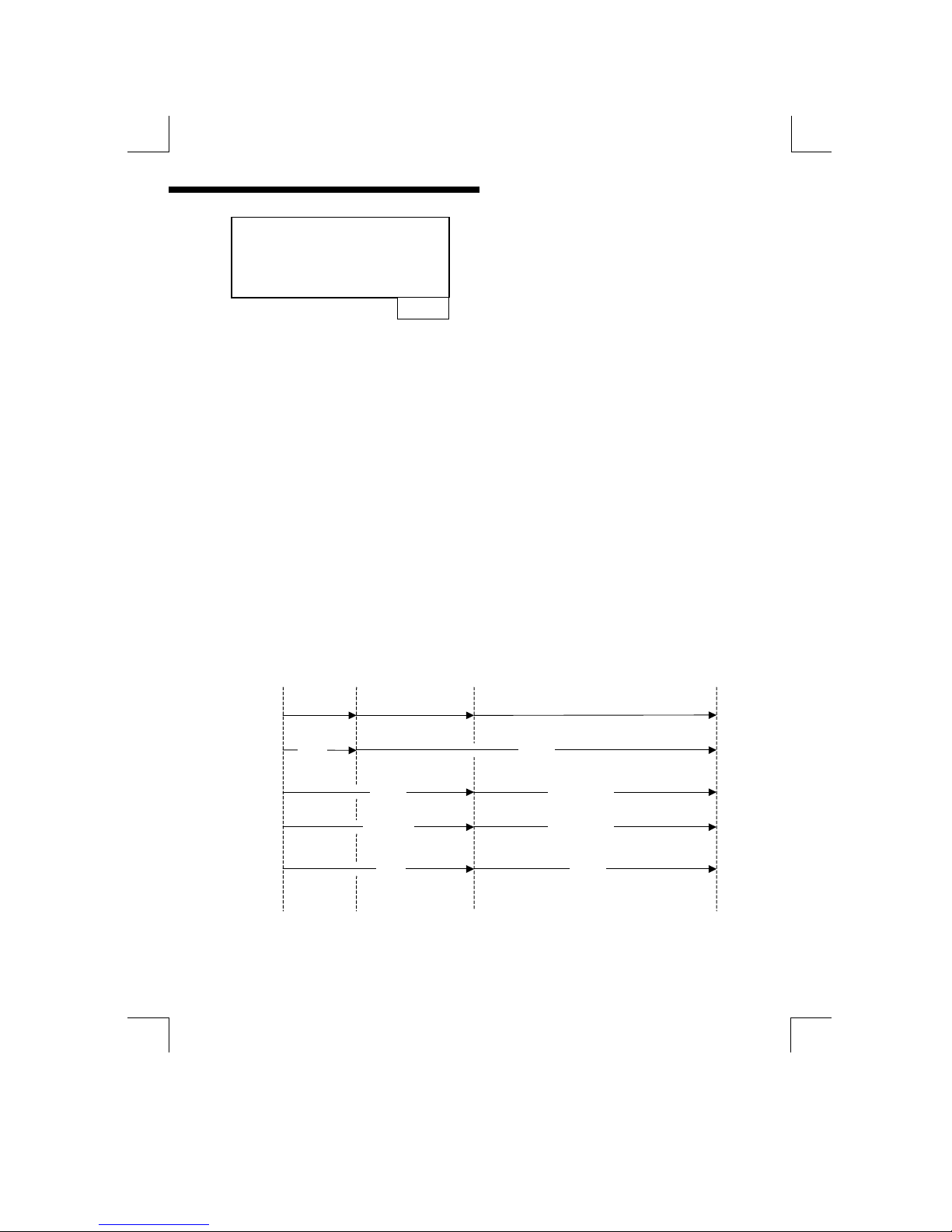
14 Sensor Cleaning
74
Cleaning Delay Y
N
When operating in “On-Line” state, “Y”
forces the cleaning to wait until all
relays are inactive.
(Only appears when state = “On-Line”)
Manually taking the instrument Off-Line will prohibit or terminate a “Clean” cycle. If
the instrument is Off-Line when a “Clean” cycle is requested, either automatically
or manually, the message “Cleaning Delayed” will flash on the bottom row of the
display until it is either cancelled using the “ENTER” key, or cleaning is initiated by
placing the unit back in the On-Line state. The instrument can be taken Off-Line
during a “Clean” cycle. This will de-energise the set point relays and freeze the
current output which could otherwise cause chaos in the control system as a result
of cleaning solution being sprayed onto the sensor.
By selecting the automatic Off-Line facility in the menu, spurious relay / current
output changes are prevented during the Duration and Recover periods. Normal
operation is restored during the Interval period. The clean Delay function gives
priority to the control relays. This means that a “Clean” cycle will be delayed for as
long as necessary until the control relays are in the “Off” state.
A manual clean cycle can be initiated by a remote switch/contacts connected to
the instrument digital input terminals. The “Clean” cycle software runs
automatically and continuously from power up if selected, beginning with the
Interval period. It can only be stopped by changing the operating mode of the
output which it is controlling.
Typical Operation with Clean Offline
Duration
Clean
Relay
Set point
Relay
Current
Output
Offline
Lamp
on
Recovery Interval
off
off
offon
Hold
Normal
Normal
Page 76

15 Fault Finding
75
15 Fault Finding
NOTE : THERE ARE NO USER SERVICEABLE PARTS INSIDE THE UNIT
The MOD53 has been designed to include a wide range of self diagnostic test,
some of which are performed at switch on, and some on a continuous basis. This
guide aims to provide a route to diagnosing and correcting any faults that may
occur during normal operation. The table shown, gives a list of the error messages
that the MOD53 generates, along with their probable causes. If the fault has
not been cleared after these checks have been made contact LTH. Please have
as much of the following information available as possible in any communication
with LTH, to enable quick diagnosis and correction of the problem.
1. Serial number of the instrument,
2. The approximate date of purchase.
3. Software Version (Displayed at Switch On)
4. Details of the program settings and application
5. Electrical environment and supply details
6. Circumstances under which the fault occurred.
7. The nature of the fault or faults
8. Any error messages that are displayed
9. The sensor type, cable length and type
10. Current output configuration
11. Relay connection configuration
It is often worthwhile to check the measurement by an independent method, for
example using a handheld meter. See also Noise Suppression.
The Instrument Appears Dead
Check that power is available to the unit . Use an appropriate voltmeter to check
that the power supply voltage at the connector is within the limits defined on the
connector label. Check that the power cable is securely and correctly attached.
There are no user serviceable fuses fitted within this unit.
The Access Code Does Not Work
It is probable that the access code has either been changed or the operator does
not recall the code correctly. Contact LTH or your local distributor should this
problem arise.
The Sensor Reading Is Constantly Over-range or Under-range
♦
Ensure that the sensor and temperature inputs are correctly connected, and
check that the sensor is not faulty or damaged.
♦
Check that the correct probe type has been selected ensure all probe
protective caps have been removed.
♦
Check that any junction boxes used are correctly connected.
♦
Check for damaged or broken cables.
Page 77

15 Fault Finding
76
♦
Where extension cables have been used, try connecting the sensor directly to
the instrument.
♦
Check the sensor using a hand held meter.
The Sensor Reading Is Incorrect
♦
Check the temperature compensation mode. If the compensation is set to
“Manual” check that the fixed temperature is at the correct level. If the
compensation is “Automatic” check that the temperature reading on the main
display is correct.
♦
Use another instrument to check the sensor.
♦
Check that the sensor gives sensible readings in air (100%) and Sodium
Sulphite Solution (0%)
♦
Check the Pressure and Salinity Compensation values
♦
Check that no error messages are being displayed.
The Temperature Reading Is Incorrect
♦ Check that the temperature sensor is correctly attached.
♦ Check that the temperature sensor type is correctly selected in the
“Configuration” menu.
♦
Where practical check the temperature sensor resistance against the table in
Appendix F.
♦
Check the user calibration.
Current Output is Incorrect or Noisy
♦
Check that the maximum load for the current loop has not been exceeded.
(1000Ω)
♦
Check that the terminals have been wired correctly .
♦
Check that the cable screen is attached to Earth at one end, and that the
cable does not pass too close to a power cable. Check that the current output
has been configured properly.
♦
Check the user calibration.
Pressure Input is Incorrect or Noisy
♦
Check that the maximum load for the current loop has not been exceeded.
♦
Check that the terminals have been wired correctly and that the cable screen
is attached to Earth at one end. Make sure that the cable does not pass too
close to a power cable.
♦
Check that the Pressure Input has been configured properly. Try performing a
user calibration.
Page 78

15 Fault Finding
77
Relays Appear to Malfunction
♦
Check that the unit is “On-Line”
♦
Check that the set point configuration is correct
♦
If the relays are vibrating or “chattering” as they pass the set point, check the
hysteresis setting and increase if necessary.
♦
Ensure that the relays are connected properly and that the voltage/current
levels are not exceeding the specification
♦
Check that the instrument input cables are not picking up excessive noise,
A Bell Symbol is Flashing on the Display
The system has detected an error but the error messages have been disabled in
the “Configuration” menu. Enable the error messages, correct the error and then
disable the error messages only if absolutely necessary.
OE15 DO Probe Maintenance
In order to achieve the maximum reliability from the overall system the sensor will
require regular calibration and maintenance. The period for this will depend upon
the application; e.g. in aeration tanks, a weekly check on calibration and fouling
would be a reasonable estimate, for rivers a longer period, and in ditches it may
need to be more frequent. The zero check in Sodium Sulphite would be less
frequent, probably once a month.
The OE15 electrode incorporates a number of features to simplify maintenance.
The electrolyte contained within the cartridge is gelled and sealed. The cartridge is
detachable. It can be removed by undoing the large stainless steel bolt at the
bottom of the electrode.
Due to the Galvanic action of the sensor, the cartridge has a finite life. It will
provide at least 12 months of continuous use before replacement becomes
necessary. LTH Electronics operates an exchange service for electrodes, but we
recommend the purchase of a spare cartridge if the process being monitored is
continuous. The electrode should contain a weak solution of Sodium Sulphite,
which absorbs any residual oxygen in the probe and conditions the electrode for
immediate use.
Page 79

15 Fault Finding
78
This page intentionally blank
Page 80
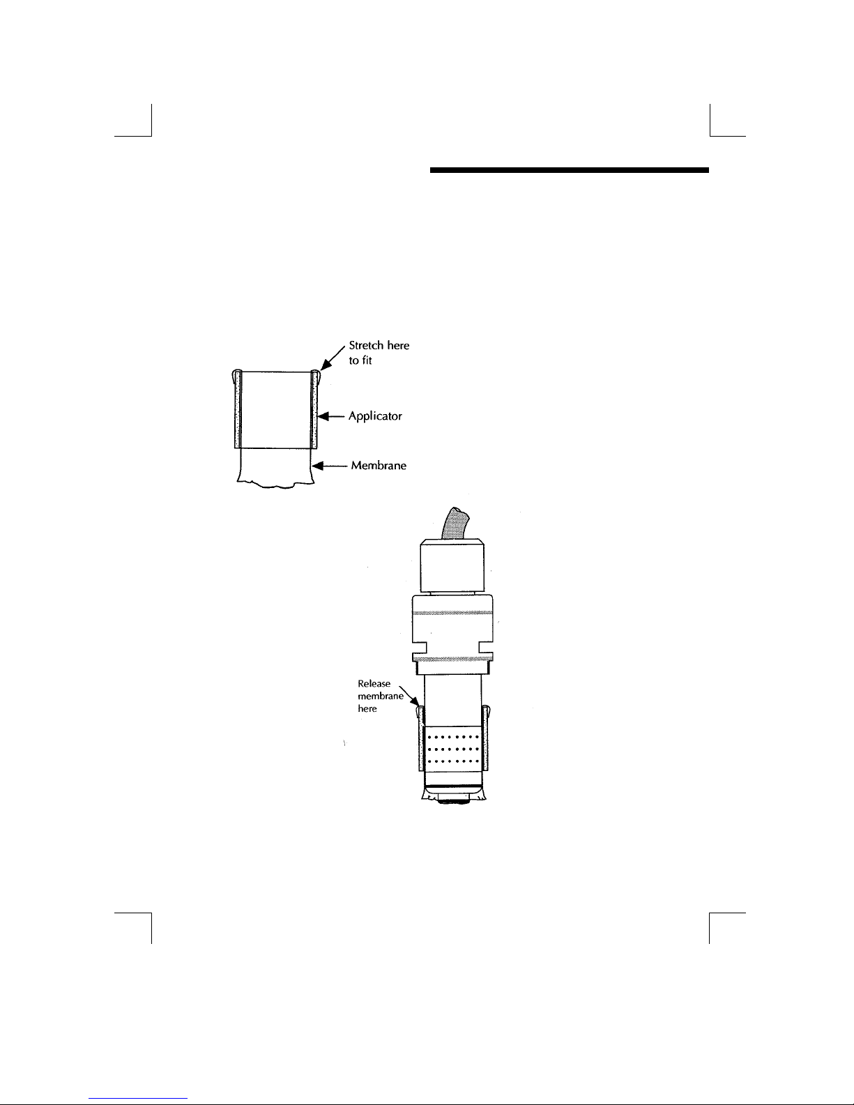
16 OE15 Membrane Replacement
79
16 OE15 Membrane Replacement
The electrode membrane is very delicate and may be damaged by careless use.
Inspect the electrode periodically for signs of membrane damage and replace it if
necessary.
Remove the damaged membrane and
the two ’O’ rings retaining it and set
these aside. Cut a 120mm length of
membrane and fit to the applicator as
shown by passing it through the middle
and evenly stretching the front edge
back over the outside. Slide the
applicator carefully over the electrode
taking care not to stretch the
membrane. Release the membrane at
the top and withdraw the applicator.
Page 81
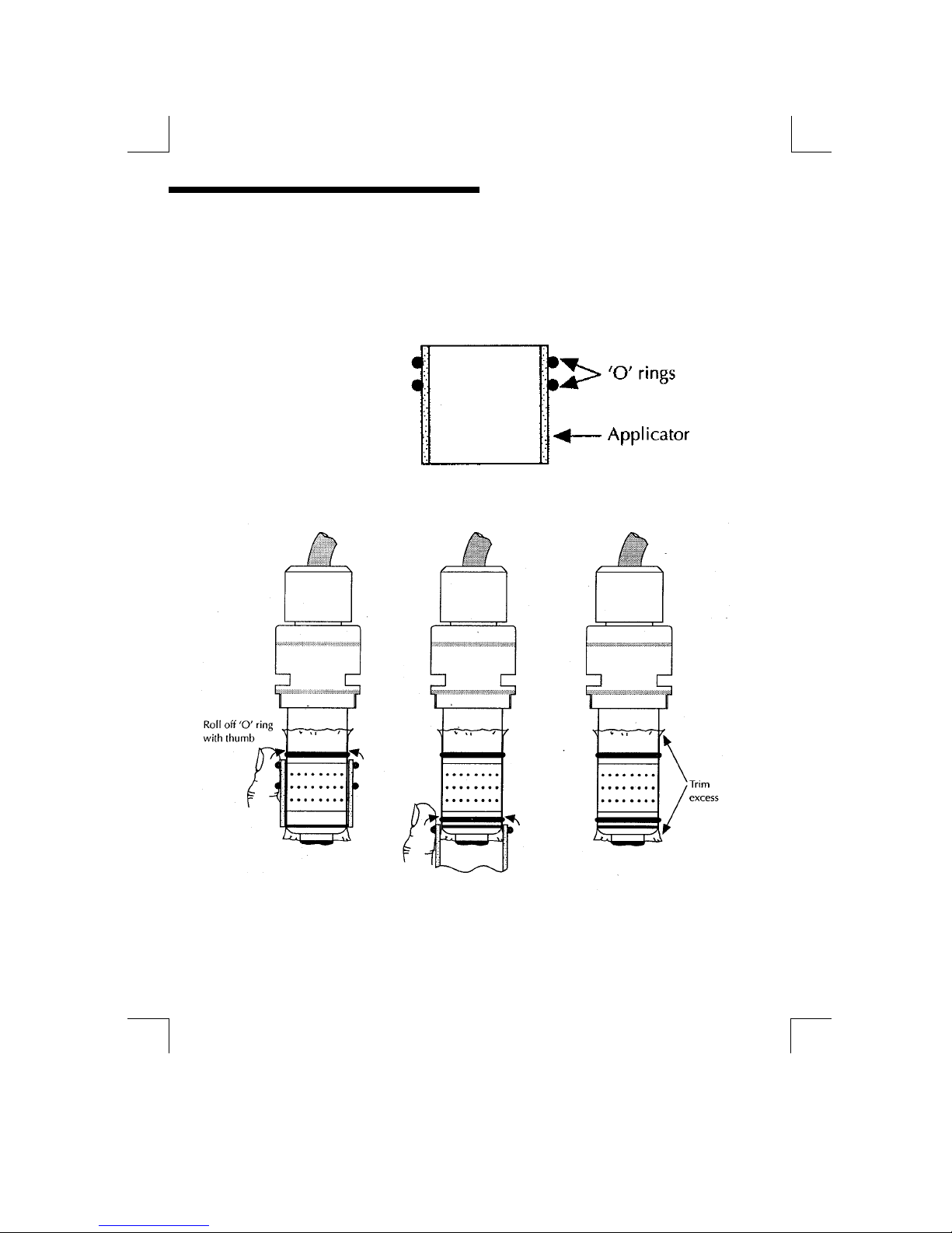
16 OE15 Membrane Replacement
80
Place the two ‘O’ rings on the applicator and slide this over the electrode taking
care not to touch the membrane covering the silver cathode. Push off the first ‘O’
ring to locate in the top groove without stressing the membrane. Fit the second ‘O’
ring in a similar fashion and trim off the excess membrane not enclosed within the
‘O’ rings.
Page 82

17 Guarantee and Service
81
17 Guarantee and Service
Products manufactured by LTH Electronics Ltd are guaranteed against faulty
workmanship and materials for a period of three years from the date of despatch,
except for finished goods not of LTH manufacture, which are subject to a separate
agreement.
All sensors made by LTH Electronics Ltd are thoroughly tested to their published
specification before despatch. As LTH have no control over the conditions in which
their sensors are used, no further guarantee is given, although any complaints
concerning their operation will be carefully investigated.
Goods for attention under guarantee (unless otherwise agreed) must be returned to
the factory carriage paid and, if accepted for free repair, will be returned to the
customer’s address free of charge. Arrangements can also be made for repair on
site, in which case a charge may be made for the engineer’s time and expenses.
If any services other than those covered by the guarantee are required, please
contact LTH direct.
N.B. Overseas users should contact their LTH nominated representative. Special
arrangements will be made in individual cases for goods returned from overseas.
Page 83

17 Guarantee and Service
82
This page intentionally blank
Page 84

Appendix A – DO Measurement
83
Appendix A – DO Measurement
Sensor Interface
The output signal from a Dissolved Oxygen probe is in the form of a constant DC
current which is proportional to the partial pressure of the liquid being measured.
In a 100% saturated solution at room temperature and pressure, the output from a
Galvanic probe will be of the order of hundreds of micro-amps (10
-6
Amps),
whereas the output from a Polargraphic probe will be of the order of hundreds of
nano-amps (10
-9
Amps).
In addition, Polargraphic probes require a bias voltage to be applied between the
cathode an anode of the DO cell to excite an output.
The equation for converting current input to % saturation is as follows :
% Saturation = (I/Io) x Pc x M x 100
Where : I = Measured Input Current
I
o
= 100% Saturation Current
P
c
= Pressure Correction Term
M = Membrane Correction Term
The pressure correction term compensates for the effect that pressure has on the
solubility of oxygen in water. This is almost directly proportional, i.e. a 10%
variation in pressure will lead to a 10% variation in the solubility and therefore
saturation of the liquid.
The pressure correction term is defined as follows :
P
o
- P
vapor(To)
P
c
= -------------------
P - P
vapor(T)
Where : Po = Pressure at 100% Calibration
P
vapor(T
= Saturation Vapour Pressure at T
P = Pressure
T = Temperature
To = Temperature at 100% Calibration
Page 85

Appendix A – DO Measurement
84
Membrane Correction
The membrane correction term is defined as follows :
M = e
A([1/T]-[1/To])
Where : A = Membrane Correction Factor
T = Temperature (in °K)
To = Temperature at calibration (in °K)
The membrane correction factor is specific to each make of probe and
characterises the type and thickness of the membrane material in terms of how its
permeability to Oxygen varies with temperature. From this, it can be seen that the
membrane correction term can contribute a variation in the saturation value of as
much as 3% for each degree of change in temperature (for a typical membrane
correction factor of 2220).
The above equations demonstrate the benefits of having active temperature and
pressure measurement when an accurate reading is required. For systems where
active pressure or temperature measurement is not available, manual
compensation is available.
Oxygen Solubility
The Oxygen solubility is easily defined as : % Saturation X Maximum Theoretical
Solubility of Oxygen in water. The maximum theoretical solubility is heavily
dependant on the temperature, pressure and salinity of the measured liquid.
Tables of data for Oxygen solubility are readily available from a number of sources
such as BS EN 25814, ISO5814 , and see solubility table.
Partial Pressure of Oxygen (pO2)
The concentration of a gas dissolved in a solution at equilibrium is proportional to
the partial pressure of the gas in contact with the solution (Henry’s Law). The
partial pressure of the gaseous component of the air in contact with the solution
remains proportional to the total pressure of the air sample.
The partial pressure of Oxygen in air at atmospheric pressure of 1 Bar (1000mBar)
is 210mBar (air is 21% Oxygen), so if a solution of pure water were 100% saturated
with Oxygen at atmospheric pressure the partial pressure of Oxygen in solution
would be 210mBar. e.g. 20% saturation at a pressure of 1 Bar gives a reading of
42mBar, 50% saturation at a pressure of 3 Bar gives a reading of 315mBar.
Page 86
Appendix B – Probe Parameters
85
Appendix B – Probe Parameters
The following table gives the necessary configuration data for a number of DO
probes :
Probe Type
Temperature
Sensor Type
Membrane
Correction
Factor
Bias
Voltage
LTH OE15 1K Thermistor
3965 N/A
BJ ProcessProbeTM 22K Thermistor
2220 +0.675V
Hamilton OxysensTM 22K Thermistor
2700 +0.670V
Page 87

Appendix B – Probe Parameters
86
This page intentionally blank
Page 88
Appendix C – Factory Default Setups
87
Appendix C – Factory Default Setups
Parameters Galvanic Polargraphic
Units % Saturation % Saturation
Probe Type Galvanic Polargraphic
Temperature Units
°C °C
Temperature Compensation Automatic Automatic
Fixed Temperature Input
+25.0°C +25.0°C
Fixed Salinity Input 0.00 ppt 0.00 ppt
Pressure Compensation Manual Manual
Pressure Units Atm Atm
Fixed Pressure Input 1.00 Atm 1.00 Atm
Set Points
SP1 Source Sensor Sensor
SP1 Trigger Low Low
SP1 Level (Latch High) 50.0% 50.0%
SP1 Latch Low 20.0% 20.0%
SP1 Mode On/Off On/Off
SP1 Dose Alarm No No
SP1 Alarm Time (mm:ss) 05:00 05:00
SP1 Delay (mm:ss) 00:00 00:00
SP1 Hysteresis
(% of SP Level)
1.0% 1.0%
SP1 Cycle Time (mm:ss) 00:30 00:30
SP1 Proportional Latch
(% of range)
20.0% 20.0%
Page 89
Appendix C – Factory Default Setups
88
Parameters Galvanic Polargraphic
SP2 Source Sensor Sensor
SP2 Trigger High High
SP2 Level (Latch High) 50.0% 50.0%
SP2 Latch Low 20.0% 20.0%
SP2 Mode On/Off On/Off
SP2 Dose Alarm No No
SP2 Alarm Time (mm:ss) 05:00 05:00
SP2 Delay (mm:ss) 00:00 00:00
SP2 Hysteresis 1.0% 1.0%
SP2 Cycle Time (mm:ss) 00:30 00:30
SP2 Proportional Band 20.0% 20.0%
SP3 Source Sensor Sensor
SP3 Trigger Latch Latch
SP3 Level (Latch High) 50.0% 50.0%
SP3 Latch Low 20.0% 20.0%
SP3 Mode On/Off On/Off
SP3 Dose Alarm No No
SP3 Alarm Time (mm:ss) 05:00 05:00
SP3 Delay (mm:ss) 00:00 00:00
SP3 Hysteresis 1.0% 1.0%
SP3 Cycle Time (mm:ss) 00:30 00:30
SP3 Proportional Band 20.0% 20.0%
SP4 Alarm Trigger Disabled Disabled
Cleaning
Duration (mm:ss) 00:05 00:05
Interval (hh:ss) 01:00 01:00
Mode Off-Line Off-Line
Recovery (mm:ss) 00:05 00:05
Delay N N
Page 90
Appendix C – Factory Default Setups
89
Parameters Galvanic Polargraphic
Current Outputs
Input A Sensor Sensor
Output A 4-20mA 4-20mA
Output A Zero 0.0% 0.0%
Output A Span 100.0% 100.0%
Input B Temperature Temperature
Output B 4-20mA 4-20mA
Output B Zero 0.0°C 0.0°C
Output B Span 100°C 100°C
Pressure Input
Mode Input Input
Units Atm Atm
4mA Level 0.40 Atm 0.40 Atm
20mA Level 2.00 Atm 2.00 Atm
Pressure Damping Disabled Disabled
Pressure Limit A (“From”) 0.00 Atm 0.00 Atm
Pressure Limit B (“To”) 0.00 Atm 0.00 Atm
Calibration
Mode On-Line On-Line
Calibration Access No No
Configuration
Language English English
T Input LTH 1K* BJ 22K**
Bias Voltage 0.000V +0.675V**
Membrane Correction Factor 3965* 2220**
Errors Enabled Enabled
Input Filter Out Out
* Default for use with the OE15 Probe
** Default for use with the ProcessProbe
TM
Page 91

Appendix C – Factory Default Setups
90
This page intentionally blank
Page 92
Appendix D – Customer Setup
91
Appendix D – Customer Setup
Instrument Serial No. : _____________________
Sensor Serial/Type No. : _____________________
Parameters
Units
Probe Type
Temperature Units
Temperature Compensation
Fixed Temperature Input
Fixed Salinity Input
Pressure Compensation
Pressure Units
Fixed Pressure Input
Set Point 1
SP1 Source
SP1 Trigger
SP1 Level (Latch High)
SP1 Latch Low
SP1 Mode
SP1 Dose Alarm
SP1 Alarm Time (mm:ss)
SP1 Delay (mm:ss)
SP1 Hysteresis
(% of SP Level)
SP1 Cycle Time (mm:ss)
SP1 Proportional Band
(% of range)
Page 93
Appendix D – Customer Setup
92
Set Points 2 - 4
SP2 Source
SP2 Trigger
SP2 Level (Latch High)
SP2 Latch Low
SP2 Mode
SP2 Dose Alarm
SP2 Alarm Time (mm:ss)
SP2 Delay (mm:ss)
SP2 Hysteresis
(% of SP Level)
SP2 Cycle Time (mm:ss)
SP2 Proportional Band
(% of range)
SP3 Source
SP3 Trigger
SP3 Level (Latch High)
SP3 Latch Low
SP3 Mode
SP3 Dose Alarm
SP3 Alarm Time (mm:ss)
SP3 Delay (mm:ss)
SP3 Hysteresis (% of SP)
SP3 Cycle Time (mm:ss)
SP3 Proportional Band
(% of range)
SP4 Alarm Trigger
Cleaning
Duration (mm:ss)
Interval (hh:ss)
Mode
Recovery (mm:ss)
Delay
Page 94
Appendix D – Customer Setup
93
Current Output
Input A
Output A
Output A Zero
Output A Span
Input B
Output B
Output B Zero
Output B Span
Pressure Input
Mode
Units
4mA level
20mA Level
Damping
Limit A (“From”)
Limit B (“To”)
Calibration
Mode
Calibration Access
Configuration
Language
T Input
Bias Voltage
Membrane Correction
Errors
Input Filter
Page 95

Appendix D – Customer Setup
94
This page intentionally blank
Page 96

Appendix E – Calibration
95
Appendix E – Calibration
Calibration Procedures
Normal good practices should be observed when calibrating DO systems. When
the instrument is first connected to the oxygen sensor, i.e. when the unit is first
installed, or whenever the oxygen sensor is changed or the membrane replaced,
the user should perform a zero check and span calibration of the system using the
following procedure. If necessary the user can use a span calibration other than
100% by simply setting the span calibration level in the “Set Span Level” item in
the “Calibration” menu.
Notes.
• As an aid to stable air calibration, a partially covered bucket can be used to
shield the sensor from the temperature variations which arise from exposure to
the wind and sunlight.
• It is recommended that because the OE15 oxygen cartridge has a finite life, a
spare cartridge should be stocked where a significant down time is not
acceptable to the application.
• The OE15 sensor requires a minimum fluid flow of 0.5ms
-1
to refresh the
depletion layer which forms around the sensor membrane. This applies to both
air and solution readings.
• All calibration is done in % Saturation, even if the required operating mode is
concentration.
• Approximate sensor current is 700uA = 100% Sat with Galvanic sensor and
60nA = 100% Sat with Polargraphic sensor.
Zero Check in a de-oxygenated solution
• Prepare a fresh solution of approximately 2% wt/vol. of sodium sulphite in demineralised water.
• Wash off any process chemicals or water from the sensor, which may
contaminate the solution. Use de-mineralised water or follow the
manufacturers cleaning instruction as necessary.
• Set the instrument to read Current.. Select % saturation as the secondary
reading. Allow the output to settle in air at (or close to) 100% saturation. Place
the sensor in the sodium sulphite solution and observe the current reading.
The reading should drop below 10% of the air saturated reading within 35
seconds.
• If this time is exceeded, cycle the sensor between the free air and the solution
to improve the speed of the response. If cycling it 3 or 4 times does not
improve the response significantly, store the sensor overnight in the solution
and then re-test it with a fresh solution the following day. If it still does not
respond within the specified time the cartridge membrane should be checked
and replaced if necessary, otherwise the electrolyte will have to be replaced
(this must be done at the factory for OE15 probes).
Page 97

Appendix E – Calibration
96
• If the sensor responds quickly enough, check that within another 3 minutes the
current reading has fallen to virtually zero (less than 5µA).
• If the current reading is greater than 5µA, select the “Zero Cal” function form
the main menu, or from the calibration menu. Press the “ENTER” key and the
unit will correct the 0% saturation point to the current input at this point.
Span Calibration in Free Air
• The frequency of this check depends upon the application, but should be made
generally once a month.
• Wash off any process chemicals or water from the sensor. Use de-mineralised
water or follow the manufacturers cleaning instructions as necessary.
• Set the instrument to read Current. Select % saturation as the secondary
reading.
• Stabilise the sensor by leaving it in the process solution for up to 10 minutes.
This will allow the temperature compensator networks to reach equilibrium.
• Lift the sensor so that it is just above the process solution, and therefore as
close to the temperature of that solution as possible. Observe the instrument
readings and wait until the output stabilises. If necessary enable the sensor
filter to obtain a stable reading.
• If necessary check and set the calibration level (100%) in the “Calibration”
Menu.
• Select the “Span Cal” function from the main menu, or from the calibration
menu. Press the “ENTER” key and the unit will correct the 100% saturation
point to the current input at this point.
• Enter the Pressure level at the span calibration from within the calibration
menu. It is important to have the sensor pressure level correctly entered,
especially when the sensor is measuring in a system where pressure can vary
over a wide range. If automatic Temperature compensation is selected the unit
will automatically store the measured temperature at the instance of the 100%
span calibration. If, however, the Temperature compensation is “Manual”, the
user will need to ensure that the “fixed” temperature input is set to the
temperature the sensor is experiencing at the instance of calibration, as this will
be taken as the calibration temperature.
Page 98
Appendix F – Temperature Sensor Data
97
Appendix F – Temperature Sensor Data
The table below lists approximate resistance values of temperature sensors that
may be used with the MXD53 series. Not all options are available on all models.
Temperature
(°°°°C)
PT1000
RTD**
LTH 1K
Thermistor
BJ 22K
Thermistor
0
1000.0Ω 2691Ω 64.88 kΩ
10
1039.0Ω 1779Ω 41.34 kΩ
20
1077.9Ω 1204Ω 26.97 kΩ
25
1097.3Ω 1000Ω 22.00 kΩ
30
1116.7Ω 833.7Ω 18.03 kΩ
40
1155.4Ω 589.0Ω 12.30 kΩ
50
1194.0Ω 423.9Ω 8.57 kΩ
60
1232.4Ω 310.5Ω 6.07 kΩ
70
1270.7Ω 231.0Ω 4.38 kΩ
80
1308.9Ω 174.5Ω 3.21 kΩ
90
1347.0Ω 133.6Ω 2.39 kΩ
100
1385.0Ω 103.6Ω 1.80 kΩ
** For a PT100 RTD, divide the PT1000 values by 10
Page 99

Appendix F – Temperature Sensor Data
98
This page intentionally blank
Page 100
Appendix G – Pressure Conversions
99
Appendix G – Pressure Conversions
The following table provides conversions between all the common pressure units
mm Hg
760
750
7.50
73.36
51.72
1
psi
14.696
14.504
0.145
1.422
1
0.0194
m H
2
0
10.33
10.20
0.102
1
0.703
0.0136
kPa
101.33
100
1
9.81
6.895
0.133
Bar
1.0133
1
0.01
0.0981
0.069
0.00133
Atm
1
0.987
0.00987
0.0968
0.061
0.00132
Atm
Bar
kPa
m H
2
0
psi
mm Hg
 Loading...