

Page 1
The Innovation Company
LTG Aktiengesellschaft
Instructions for Installation, Use
and Maintenance
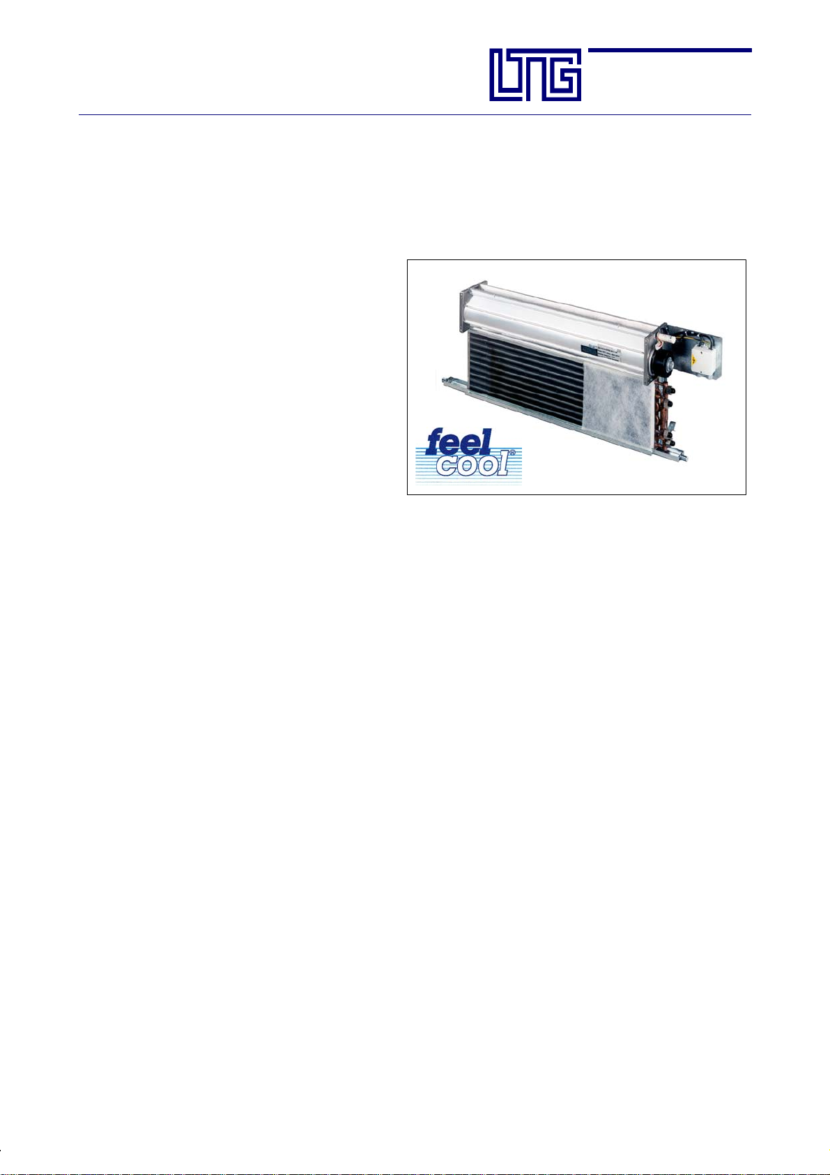
Fan Coil Unit VFC
Example:
Fan coil unit for sill installation
LTG Aktiengesellschaft
D - 70435 Stuttgart, Grenzstraße 7
D -- 70405 Stuttgart, Postfach 40 05 25
+49 (0711) 82 01-0 Fax +49 (0711) 82 01-720
Internet: http://www.LTG-AG.de
E-Mail: [email protected]
AG-- B 201.1e (Feb. 10)
Page 2

Page 3
The Innovation Company
LTG Aktiengesellschaft
Instructions for Installation, Use and Maintenance
Fan Coil Unit Type VFC
Table of contents
EC Declaration of Conformity 5
Safety Instructions 7
1 Transport and Storage 9
1.1 Transport Instructions 9
1.2 Storage 9
2 Function 10
2.1 Intended use 10
3 Technical Specifications 11
3.1 Specifications, Dimensions 11
3.2 Caloric Output Data 28
3.3 Acoustic Data 28
3.4 Hydraulic Data 28
3.5 Weight 29
3.6 Electrical Data 29
4 Installation 31
4.1 Installation / Suspension 31
4.2 Water Connections 34
4.3 Condensate Connection 40
4.4 Check after Installation 41
5FirstUse 42
6 Operation, Maintenance and Repair 43
6.1 Heat Exchanger, Water Connections and Condensate Tray 43
6.2 Filter 43
6.3 Fan 43
6.4 Repair 44
6.5 Trouble Shooting and Corrective Action 45
6.6 Maintenance Interval s of the Individual Components 47
7 Spare Parts 48
8 Decommissioning and Disposal 48
Section:
Page:
Date:
AG--B 201.1e
3
Feb. 2010
E LTG Aktiengesellschaft ⋅ Grenzstraße 7 ⋅ D-70435 Stuttgart ⋅ +49 (0711) 8201-0 ⋅ Fax -720
Internet: http://www.LTG-AG.de ⋅ E-Mail: [email protected] ⋅ Printed in Germany ⋅ Ausgaben mit früherem
Datum werden hiermit ungültig ⋅ Technische Änderungen vorbehalten ⋅ Former editions are invalid ⋅ Subject to technical modifications.
Page 4

Page 5
The Innovation Company
LTG Aktiengesellschaft
Instructions for Installation, Use and Maintenance
Fan Coil Unit Type VFC
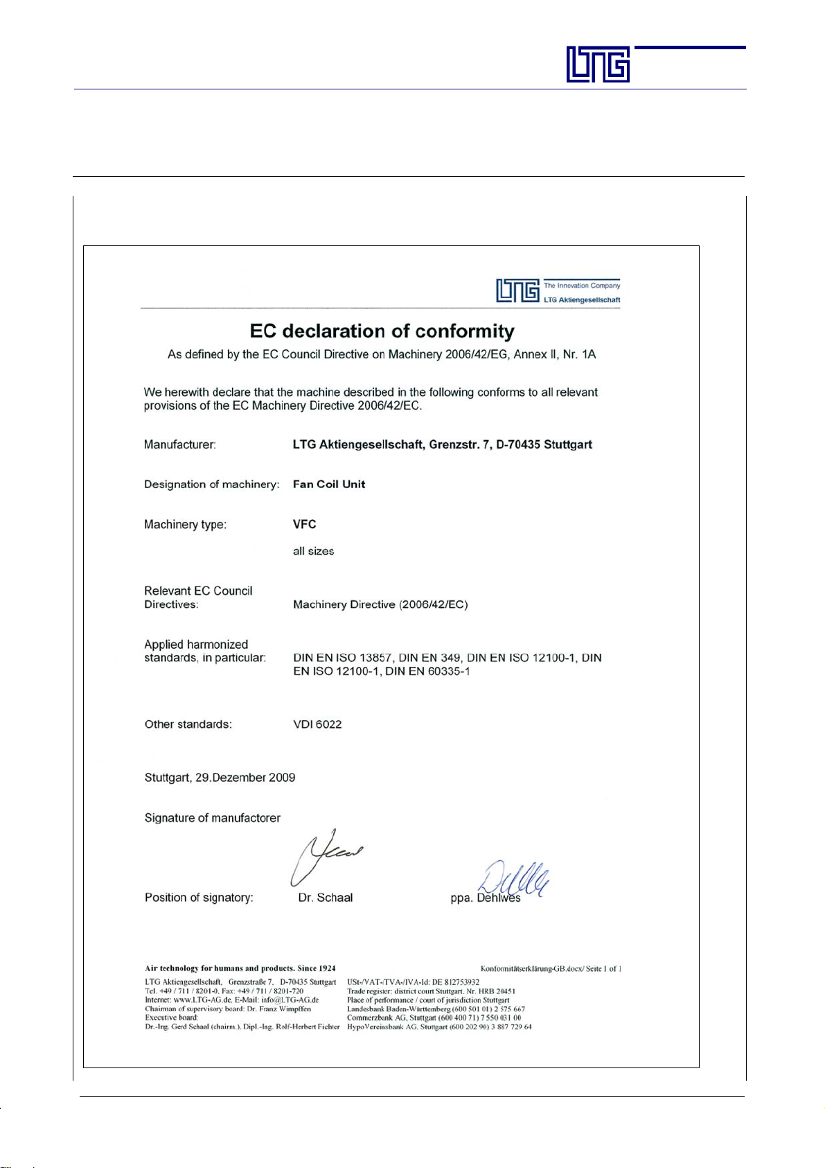
EC Declaration of Conformity
Section:
Page:
Date:
AG--B 201.1e
5
Feb. 2010
E LTG Aktiengesellschaft ⋅ Grenzstraße 7 ⋅ D-70435 Stuttgart ⋅ +49 (0711) 8201-0 ⋅ Fax -720
Internet: http://www.LTG-AG.de ⋅ E-Mail: [email protected] ⋅ Printed in Germany ⋅ Ausgaben mit früherem
Datum werden hiermit ungültig ⋅ Technische Änderungen vorbehalten ⋅ Former editions are invalid ⋅ Subject to technical modifications.
Page 6

Page 7
The Innovation Company
LTG Aktiengesellschaft
Instructions for Installation, Use and Maintenance
Fan Coil Unit Type VFC
Carefully read the safety instructions before using any LTG fan coil unit.
Always follow the safety instructions!
Safety Instructions
The units meet any pertinent safety standards.
The installation and maintenance of air conditioning units may be dangerous because of high
pressures and electrical componentsbeing alive. Therefore, the installation,maintenance, and repair must be performed by qualified and trained staff only.
In particular electrical connections are to be provided, removed, or modified by authorized persons only observing all relevant safety instructions.
Safety instructions in the technical documentation and on unit labels must be followed at alltimes.
Do not open the unit for cleaning, maintenance, or repair and do not remove covers and casings
(air diffuser) unless all conducting lines have been completely disconnected. Do not connect or
remove the plug--in connector when under tension.
Any work regarding the electrical equipment is to be performed by skilled and trained staff only.
Connections to the main power supply and the safety earth terminal must be executed exactly as
described in the wiring diagram.
Electrical operation of the unit in a partly disas sembled condition or of individual components
is not permitted since earth terminals might be interrupted.
The standard version of the heat exchangers is designed for an operating pressure of10 bar (test
pressure 16 bar).Highwater pressuresmay be hazardous. Higher operatingpressures,therefore,
require LTG’s express permission. Wear safety glasses.
During continuous operation the motor may reach temperatures of up to 65 _C. If necessary, allow the motor to cool off or wear gloves.
Be careful when performing work on the heat exchangers. Blades and housing parts are sharp-edged. Wear gloves during work and handling.
Be careful when working overhead and provide protection against parts falling from above.
Never remove the protective grille of the fan impeller and the motor cover during operation.
Keep objects and dirtfromenteringthe impeller. A damaged fan impeller orobjects being ejected
by the impeller may be hazardous.
The casing on site also serves as a protection and should be removed for maintenance and cleaning only.
Avoid any additional load to the unit or the suspensions since stability might be insufficient.
In the heating mode a temperature of up to 80 _C may be achieved. Water--carrying parts may
be hot so do not touch with your bare hands to avoid burns.
The unit must be checked by an expert immediately
- if it has been mechanically damaged or is suffering from a water damage,
- if the fan shows signs of damages (imbalance, damage to the bearing or motor),
- if the suspension or the casing show clear signs of corrosion or ageing.
Do notput the unit back into operation before all necessary maintenance and repair has been performed!
Take the unit entirely off the main power supply until all repairs have been completed even if this
might result in not being able to operate undamaged units
It is in any case imperative to take a damaged unit completely off the main power supply!
Section:
Page:
Date:
AG--B 201.1e
7
Feb. 2010
E LTG Aktiengesellschaft ⋅ Grenzstraße 7 ⋅ D-70435 Stuttgart ⋅ +49 (0711) 8201-0 ⋅ Fax -720
Internet: http://www.LTG-AG.de ⋅ E-Mail: [email protected] ⋅ Printed in Germany ⋅ Ausgaben mit früherem
Datum werden hiermit ungültig ⋅ Technische Änderungen vorbehalten ⋅ Former editions are invalid ⋅ Subject to technical modifications.
Page 8

Page 9
The Innovation Company
LTG Aktiengesellschaft
Instructions for Installation, Use and Maintenance
Fan Coil Unit Type VFC
1. Transport and Storage
The unit requires dry and dust--free conditi ons during transport, storage, installation, and operation.
The unit is supplied i n corrugated board boxes secured with straps.
Units are stacked on Euro or single trip pallets and secured with straps. Pallets may be moved using forklifts
or cranes.
Do not remove thepackaging unless immediatelyprior toinstallation onsite to protect the unit from pollution
and damages.
LTG Aktiengesellschaft will not take responsibility for any pollution of or
damages to the unit.
1.1 Transport Instructions
Handle units appropriately and with care during transport.
Do not throw, let drop to the ground or bump into other items or walls.
Make sure that units are safely fastened during transport and avoid damage through other items.
It is recommended to always have units ha ndled by at least two persons.
The packaging is not
weather--resistant.
Section:
Page:
Date:
AG--B 201.1e
9
Feb. 2010
1.2 Storage
Make sure that units are entirely protected against weathe ring, humidity, and other adverse conditions that
might result in damages during storage.
The storage location must meet the following climatic requirements:
Temperature between +5 _C and +55 _C with a relative humidity of 90 % max. (non--condensing).
E LTG Aktiengesellschaft ⋅ Grenzstraße 7 ⋅ D-70435 Stuttgart ⋅ +49 (0711) 8201-0 ⋅ Fax -720
Internet: http://www.LTG-AG.de ⋅ E-Mail: [email protected] ⋅ Printed in Germany ⋅ Ausgaben mit früherem
Datum werden hiermit ungültig ⋅ Technische Änderungen vorbehalten ⋅ Former editions are invalid ⋅ Subject to technical modifications.
Page 10
The Innovation Company
LTG Aktiengesellschaft
Instructions for Installation, Use and Maintenance
Fan Coil Unit Type VFC
2. Function
The fan coil unit is a recirculating air unit for cooling or heating (2--pipe) or for cooling and heating (4-- pipe)
the air.
These fan coil units have been designed for installation in sills and ceilings in office and conference rooms,
hotel rooms, hospitals and other closed rooms for indoor air treat ment.
The fan sucksin ambient air via a heat exchanger, heating or cooling the air and reintroducing it into the room.
Uniform distribution of the air across the entire fan is ensured by a cross--flow impeller extending over the
entire width. The heat exchanger is usually equipped with a filter for protection.
Thermal e nergy transport to the heat exchanger is performed by water; water connecti on on the right or left.
If the cold water temperature drops in the cooling mode below dew point the condensate will be collected by
a condensate tray with possible connecting socket. For reasons of hygiene, the unit should be dimensioned
in a wayto ensure that no condensation occurs during standard operation. For operation below dew point insulated units are available.
Output is water--side controlled by valves.
The fan speed is controlled by a five--speed capacitor motor with low energy consumption, with individual
switch activation.
For group activation a total of 5 units may be connected in parallel.
Take care to connect in parallel identical speeds only, i.e. connect speed I of unit 1 to speed I of unit 2, etc.
With view to dimensioning, the most important da ta are the caloric output, the sound power level and the air
flow rate.
The units’ caloric output is determined through the fan speed, the waterflow rate, and the valve setting which
may be controlled by a regulating device.
The units’ sound power and the air flow rate are determined through the fan speed.
The use of a filter results, at the same speed level, in a reduction of both the caloric output and the air flow
rate while the sound power level of the units is higher when increasing the fan speed.
Section:
Page:
Date:
AG--B 201.1e
10
Feb. 2010
2.1 Intended Use
The LTG fan coil unit type VFCG is intended for use in closed rooms.
It is designed for ambient tempera tures of +5 _Cto+40_C and a maximum relative humidity of up to 90%
(non--condensing).
In order to ensure safe motor functioning the ambient te mperature when i nstalled should not exceed +40 _C.
The maximum admissible supply temperature is, therefore, limited to +80 _C.
Any other operating conditions require the express and written permission of LTG Aktiengesellschaft.
LTG Aktiengesellschaft does not assume responsibility for any damages resulting from unint ended use.
E LTG Aktiengesellschaft ⋅ Grenzstraße 7 ⋅ D-70435 Stuttgart ⋅ +49 (0711) 8201-0 ⋅ Fax -720
Internet: http://www.LTG-AG.de ⋅ E-Mail: [email protected] ⋅ Printed in Germany ⋅ Ausgaben mit früherem
Datum werden hiermit ungültig ⋅ Technische Änderungen vorbehalten ⋅ Former editions are invalid ⋅ Subject to technical modifications.
Page 11
The Innovation Company
LTG Aktiengesellschaft
Instructions for Installation, Use and Maintenance
Fan Coil Unit Type VFC
3. Technical Specifications
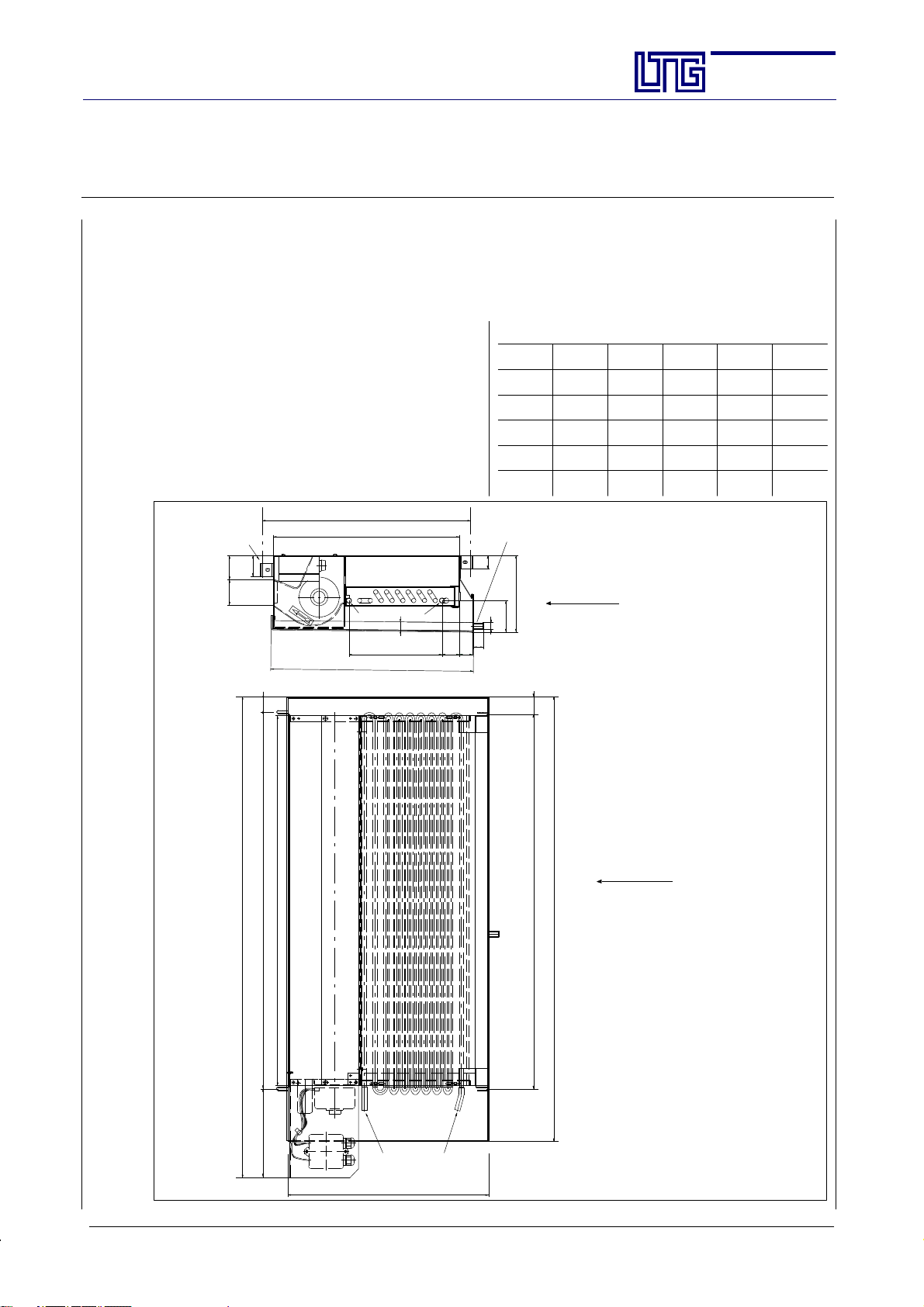
3.1 Specifications, Dimensions
Ceiling Unit, 2-pipe System
Specification
Fan coil unit with one heat exchanger for heating or
cooling the ambient air. Water-sid e control by valves.
Particularly low “built-in” depth and height, therefore
especially appro pr iatefor a room-savinginstallation in
ceilings.For extremely low inlet temperatures an insulated drain tray is available for insertion on site.
Horizontal installation (in the ceiling). Water connection on the right or left.
Mounting suspension with threaded
rodØ6mm
air outlet
width
58 56
48
35
483
431
RL
469 incl. insulation
216
20
VL
40
30
Section:
Page:
Date:
AG--B 201.1e
11
Feb. 2010
Dimensions
Size A B C D E
500 784 527 725 543 538
630 884 627 870 643 638
800 1114 857 1030 873 868
1000 1314 1057 1230 1073 1068
1250 1514 1257 1470 1273 1268
Condensate drainage
30
VL = water inlet
RL = water return
Vie w
73
15
total height 178
22
Hint for Installation:
For horizontal installation, the cooler
40
must be angled by 10_ in order to allow the condensate drainage and to
avoid condensate between the blades of
the heat exchanger.
This special arrangement will only be
required if a constant condensate formation is to be expected, i.e. if the temperature of the cold water supply will
constantly remain more than 2 K below
the dew point of the ambient air.
Vie w
Water connection:
drain tray, dimension C
unit width, dimension A
cross-- flow fan width, dimension B
unit suspension fan--side, dimension D
205
12 mm Cu tube with
Top vi e w
E LTG Aktiengesellschaft ⋅ Grenzstraße 7 ⋅ D-70435 Stuttgart ⋅ +49 (0711) 8201-0 ⋅ Fax -720
Internet: http://www.LTG-AG.de ⋅ E-Mail: [email protected] ⋅ Printed in Germany ⋅ Ausgaben mit früherem
Datum werden hiermit ungültig ⋅ Technische Änderungen vorbehalten ⋅ Former editions are invalid ⋅ Subject to technical modifications.
rapid action coupling
465
View: direction of air (arrow)
Unit as illustrated:
Water connection on the left
(or on the right, as required)
Motor always on the left
unit suspension heat exchanger-- side, dimension E
If water connection on the right,
unit width (dim. A) is extended by 80 mm
Connection heat exchanger:
shown 12 mm Cu--tube,
other dimensions with connection
1/2” internal thread.
Please note:
Position and size of the inspection openings
must meet constructional requirements
Page 12
The Innovation Company
LTG Aktiengesellschaft
Instructions for Installation, Use and Maintenance
Fan Coil Unit Type VFC
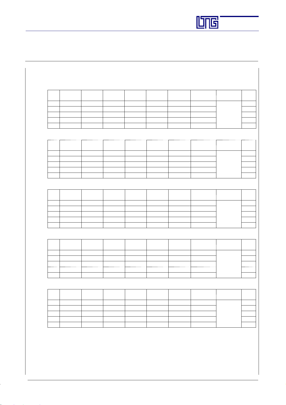
Technical Specifications, Ceiling Unit, 2-pipe System (legend see page 20)
Size 500
n
[-]V[m
3
/h]
L
A18
[dB(A)]
L
wA
[dB(A)]
Q
I 160 24 30 37 36 864 720
II 240 29 35 49 48 1152 960 15
III 290 35 41 57 56 1265 1120 18
IV 340 38 44 64 64 1408 1280 20
V 430 45 51 73 73 1576 1460 27
Size 630
n
[-]V[m
3
/h]
I 170 23 29 48 43 1032 860
II 260 27 33 59 59 1416 1180 15
III 310 34 40 68 68 1536 1360 18
IV 370 38 44 76 76 1672 1520 20
V 480 45 51 87 87 1879 1740 27
L
A18
[dB(A)]
L
wA
[dB(A)]
Q
koF
[W/K]
koF
[W/K]
/t
/t
1
Q
1
Q
kmF
[W/K]
kmF
[W/K]
/t
/t
Section:
Page:
Date:
1
2
Q
k
[W]
mF
Q
ksens
[W]
mF
2
[kg/h]/[kPa]
AG--B 201.1e
12
Feb. 2010
wo/p
P
w
[W]
el
12
200/18
1
2
Q
k
[W]
mF
Q
ksens
[W]
mF
2
wo/p
w
[kg/h]/[kPa]
P
[W]
el
12
200/20
Size 800
n
[-]V[m
L
3
/h]
A18
[dB(A)]
L
wA
[dB(A)]
Q
koF
[W/K]
/t
1
Q
I 220 23 29 52 48 1152 960
II 320 26 32 72 64 1536 1280 15
III 380 32 38 83 78 1762 1560 18
IV 460 36 42 95 92 2024 1840 20
V 580 43 49 105 105 2268 2100 28
kmF
[W/K]
/t
1
2
Q
k
[W]
mF
Q
ksens
[W]
mF
2
wo/p
w
[kg/h]/[kPa]
200/22
Size 1000
n
[-]V[m
L
3
/h]
A18
[dB(A)]
L
wA
[dB(A)]
Q
koF
[W/K]
/t
1
Q
I 300 25 31 62 59 1488 1180
II 420 28 34 82 76 1968 1520 26
III 470 33 39 92 89 2079 1780 28
IV 570 37 43 104 102 2288 2040 32
V 720 45 51 114 114 2462 2280 39
kmF
[W/K]
/t
1
2
Q
k
[W]
mF
Q
ksens
[W]
mF
2
wo/p
w
[kg/h]/[kPa]
200/23
Size 1250
n
[-]V[m
L
3
/h]
A18
[dB(A)]
L
wA
[dB(A)]
Q
koF
[W/K]
/t
1
Q
I 360 25 31 80 73 1752 1460
II 470 28 34 98 92 2208 1840 26
III 570 33 39 107 104 2350 2080 28
IV 690 37 43 116 113 2486 2260 32
V 830 44 50 128 124 2678 2480 39
1
) Specific cooling capacity (noncondensing operation)
2
) Cooling capacity with the following parameters: water inlet: 6_C,
kmF
[W/K]
/t
1
2
Q
k
[W]
mF
Q
ksens
[W]
mF
2
wo/p
w
[kg/h]/[kPa]
200/25
induction air temperature before entering the heat exchanger: 26_C, 50% rel. humidity
P
[W]
12
P
[W]
22
P
[W]
22
el
el
el
E LTG Aktiengesellschaft ⋅ Grenzstraße 7 ⋅ D-70435 Stuttgart ⋅ +49 (0711) 8201-0 ⋅ Fax -720
Internet: http://www.LTG-AG.de ⋅ E-Mail: [email protected] ⋅ Printed in Germany ⋅ Ausgaben mit früherem
Datum werden hiermit ungültig ⋅ Technische Änderungen vorbehalten ⋅ Former editions are invalid ⋅ Subject to technical modifications.
Page 13
The Innovation Company
LTG Aktiengesellschaft
Instructions for Installation, Use and Maintenance
Fan Coil Unit Type VFC
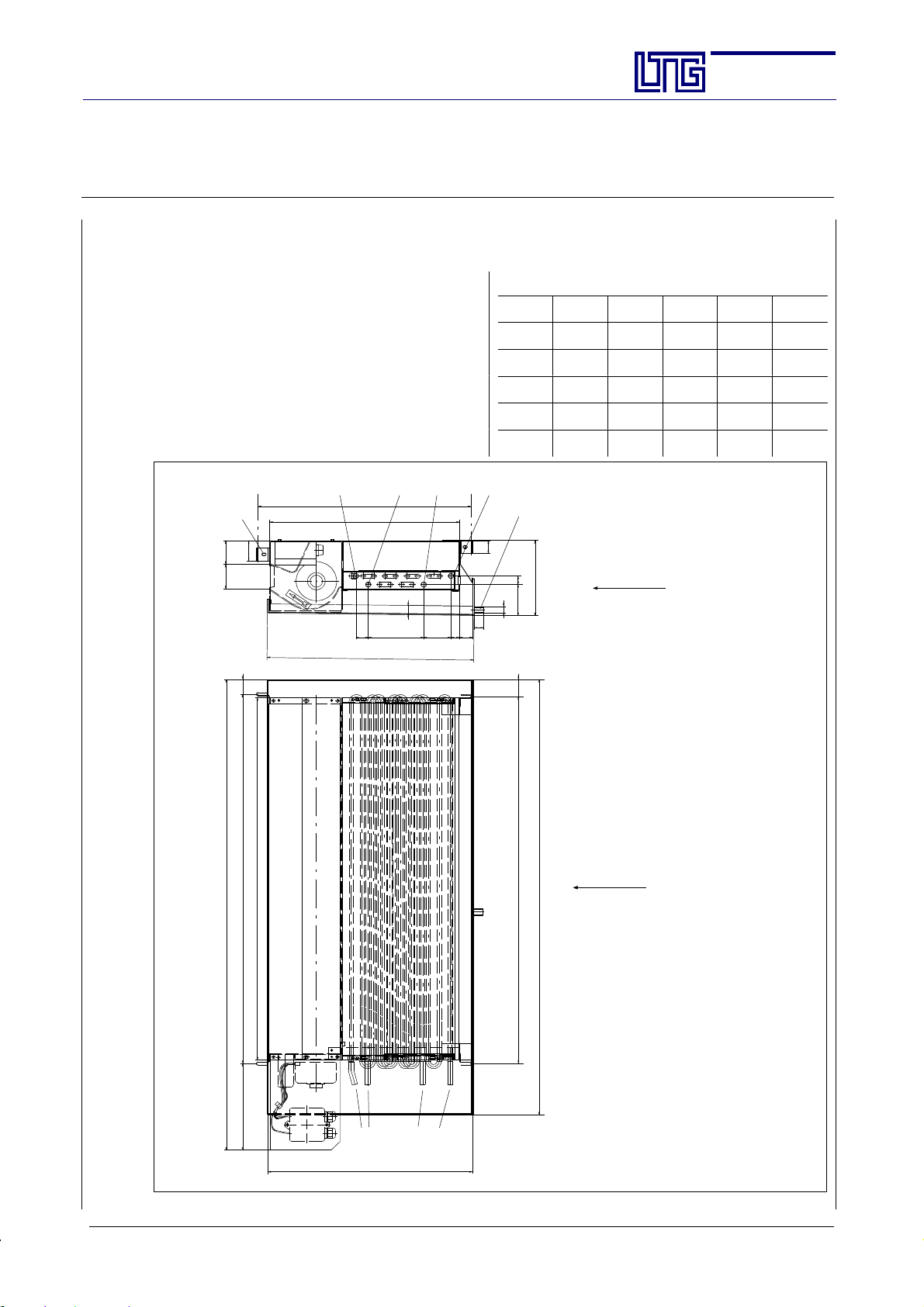
Ceiling Unit, 4-pipe System
Specification
Fan coil unit with one heat exchanger and 2 separate
cycles for heating and cooling the ambient air .
W ater-side control by valves. Particularly low “builtin” depth and height, therefore especially appropriate
for a room-saving installation in ceilings.
For extremely low inlet temperatures an insulated
drain tray is available for insertion on site. Horizontal installation (in the ceiling).
Water connection on the right or left.
Mounting suspension withthreaded
rodØ6mm
air outlet
width
58 56
48
483
431
20
29
469 incl. insulation
126
62
19
30
Section:
Page:
Date:
AG--B 201.1e
13
Feb. 2010
Dimensions
Size A B C D E
500 784 527 725 543 538
630 884 627 870 643 638
800 1114 857 1030 873 868
1000 1314 1057 1230 1073 1068
1250 1514 1257 1470 1273 1268
KKW--VLKKW--RL HZG--VLHZG--RL
Condensate drainage
30
20
KKW--VL = cooling -- water inlet
KKW--RL = cooling -- water return
HZG--VL = heating -- water inlet
HZG--RL = heating -- water return
Vie w
73
15
total height 178
22
Top vi e w
35205
Hint for Installation
40
For horizontal installation, the cooler must be
angled by 10_ in order to allow the condensate
drainage and to avoid condensate between the
blades of the heat exchanger.
This special arrangement will only be required
if a constant condensate formation is to be expected, i.e. if the temperature of the cold water
supply will constantly remain more than 2 K
below the dew point of the ambient air.
Vie w
Water connection:
drain tray, dimension C
unit width, dimension A
unit suspension fan--side, dimension D
cross-- flow fan width, dimension B
12 mm Cu tube
with rapid action coupling
465
View: direction of air (arrow)
Unit as illustrated:
unit suspension heat exchanger-- side, dimension E
Water connection on the left
(or on the right, as required)
Motor always on the left
If water connection on the right,
unit width (dim. A) is extended by 80 mm
Connection heat exchanger:
shown 12 mm Cu--tube,
other dimensions with connection
1/2” internal thread.
Please note:
Position and size of the inspection openings
must meet constructional requirements
E LTG Aktiengesellschaft ⋅ Grenzstraße 7 ⋅ D-70435 Stuttgart ⋅ +49 (0711) 8201-0 ⋅ Fax -720
Internet: http://www.LTG-AG.de ⋅ E-Mail: [email protected] ⋅ Printed in Germany ⋅ Ausgaben mit früherem
Datum werden hiermit ungültig ⋅ Technische Änderungen vorbehalten ⋅ Former editions are invalid ⋅ Subject to technical modifications.
Page 14
The Innovation Company
LTG Aktiengesellschaft
Instructions for Installation, Use and Maintenance
Fan Coil Unit Type VFC
Technical Specifications, Ceiling Unit, 4-pipe System (legend see page 20)
Size 500
n
[-]V[m3/h]
L
A18
[dB(A)]
L
wA
[dB(A)]
Q
koF
t
[W/K]
/
Q
/t
mF
[W/K]
k
1
1
I 160 24 30 34 28 672 560 21 19
II 240 29 35 46 45 1080 900 28 28 15
III 290 35 41 54 54 1220 1080 32 32 18
IV 340 38 44 60 60 1320 1200 35 35 20
V 430 45 51 68 68 1468 1360 40 40 27
Size 630
n
[-]V[m3/h]
I 170 23 29 41 36 864 720 26 23
II 260 27 33 52 51 1224 1020 32 31 15
III 310 34 40 60 60 1356 1200 35 35 18
IV 370 38 44 67 67 1474 1340 39 39 20
V 480 45 51 76 76 1641 1520 43 43 27
L
A18
[dB(A)]
L
wA
[dB(A)]
Q
koF
t
[W/K]
/
Q
/t
mF
[W/K]
k
1
1
2
Q
mF
k
[W]
2
Q
mF
k
[W]
Q
mF
Q
mF
ksens
2
[W]
ksens
2
[W]
Q
hoF
t
[W/K]
Q
hoF
t
[W/K]
Section:
Page:
Date:
/
Q
hmF
t
[W/K]
/
Q
hmF
t
[W/K]
AG--B 201.1e
14
Feb. 2010
/
wok/p
w
[kg/h]/[kPa]
200 / 13 100 / 2.5
/
wok/p
w
[kg/h]/[kPa]
200 / 14 100 / 2.7
woh/p
[kg/h]/[kPa]
woh/p
[kg/h]/[kPa]
P
w
el
[W]
12
P
w
el
[W]
12
Size 800
n
[-]V[m3/h]
L
A18
[dB(A)]
L
wA
[dB(A)]
Q
koF
t
[W/K]
/
Q
/t
mF
[W/K]
k
1
1
I 220 23 29 47 42 1008 840 29 26
II 320 26 32 64 60 1440 1200 38 36 15
III 380 32 38 74 71 1604 1420 42 41 18
IV 460 36 42 82 81 1782 1620 47 47 20
V 580 43 49 92 91 1965 1820 51 51 28
2
Q
k
[W]
mF
Q
mF
ksens
2
[W]
Q
hoF
t
[W/K]
/
Q
/
hmF
wok/p
w
woh/p
w
t
[W/K]
[kg/h]/[kPa]
[kg/h]/[kPa]
200 / 16 100 / 3.1
Size 1000
n
[-]V[m3/h]
L
A18
[dB(A)]
L
wA
[dB(A)]
Q
koF
t
[W/K]
/
Q
/t
mF
[W/K]
k
1
1
I 300 25 31 58 53 1272 1060 36 33
II 420 28 34 76 71 1704 1420 47 44 26
III 470 33 39 85 82 1853 1640 54 51 28
IV 570 37 43 95 92 2024 1840 59 57 32
V 720 45 51 107 105 2268 2100 65 65 39
2
Q
k
[W]
mF
Q
mF
ksens
2
[W]
Q
hoF
t
[W/K]
/
Q
/
hmF
wok/p
w
woh/p
w
t
[W/K]
[kg/h]/[kPa]
[kg/h]/[kPa]
200 / 18 100 / 3.4
Size 1250
n
[-]V[m3/h]
L
A18
[dB(A)]
L
wA
[dB(A)]
Q
koF
t
[W/K]
/
Q
/t
mF
[W/K]
k
1
1
I 360 25 31 74 68 1632 1360 46 43
II 470 28 34 90 85 2040 1700 54 51 26
III 570 33 39 98 96 2196 1920 61 58 28
IV 690 37 43 106 104 2288 2080 63 61 32
V 830 44 50 118 116 2505 2320 69 67 39
1
) Specific cooling capacity (noncondensing operation)
2
) Cooling capacity with the following parameters: water inlet: 6_C,
2
Q
k
[W]
mF
Q
mF
ksens
2
[W]
Q
hoF
t
[W/K]
/
Q
/
hmF
wok/p
w
woh/p
w
t
[W/K]
[kg/h]/[kPa]
[kg/h]/[kPa]
200 / 20 100 / 3.6
induction air temperature before entering the heat exchanger: 26_C, 50% rel. humidity
P
[W]
12
P
[W]
22
P
[W]
22
el
el
el
E LTG Aktiengesellschaft ⋅ Grenzstraße 7 ⋅ D-70435 Stuttgart ⋅ +49 (0711) 8201-0 ⋅ Fax -720
Internet: http://www.LTG-AG.de ⋅ E-Mail: [email protected] ⋅ Printed in Germany ⋅ Ausgaben mit früherem
Datum werden hiermit ungültig ⋅ Technische Änderungen vorbehalten ⋅ Former editions are invalid ⋅ Subject to technical modifications.
Page 15
The Innovation Company
LTG Aktiengesellschaft
Instructions for Installation, Use and Maintenance
Fan Coil Unit Type VFC
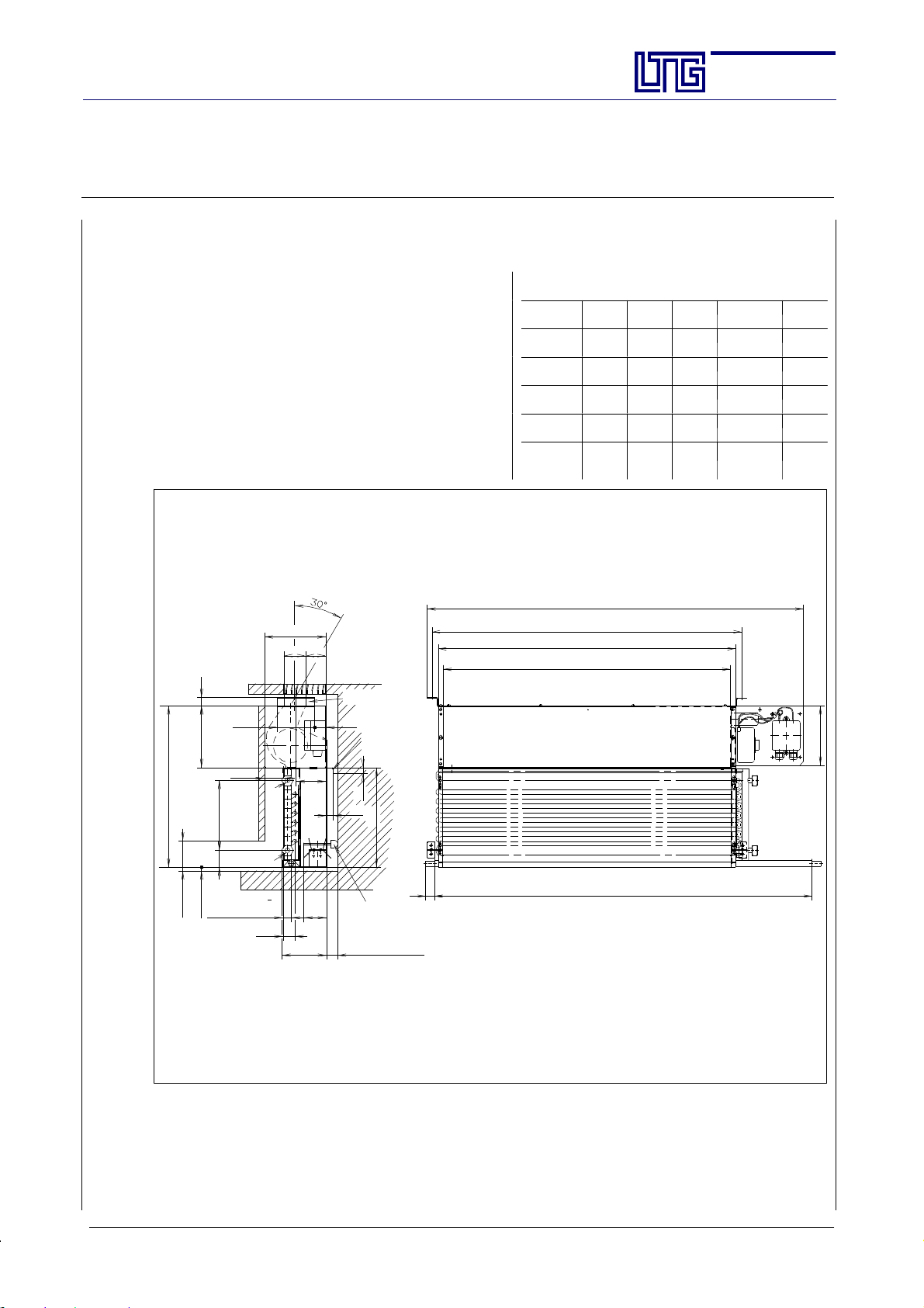
Unit for Sill Installation, 2-pipe System
Specification
Fan coil unit withone heat exchanger for heating orcooling the ambient air.
Water-side control by valves.
Particularly small built--in depth and height, therefore
especially appropriate for a room-saving installation in
sills.
For extremelylow inlet temperatures an insulateddrain
tray is available for insertion on site.
Vertical installation.
Water connection on the right or left.
Section:
Page:
Date:
AG--B 201.1e
15
Feb. 2010
Dimensions
Size A B C D E
500 527 497 563 730 755
630 627 597 663 885 855
800 857 827 893 1085 1085
1000 1057 1027 1093 1335 1285
1250 1257 1227 1293 1553 1485
431
min. 80
165
min. 10
22
100
50
18745
condensate
drainage 22
Ø15
total length, dimension E
165
55
58
air outlet
suspension from
above -- special
version
30
standard:
bracket for
rear wall
installation
(accessory)
80
RL
VL
60
32
119
15
18
266
25
rubberstop to be orderedseparately acc. to wall clearance
min. 10
without rear suspension
unit suspension, dimension C
unit length, dimension A
air outlet, dimension B
length of drain tray, dimension D
note: drain tray length may exceed
total length of unit.
RL = water return
VL = water inlet
160
power
switch
The unit may be mounted using one of the following possibilities:
- suspension from above (attachment to the sill)
- wall mounting -- rear suspension
E LTG Aktiengesellschaft ⋅ Grenzstraße 7 ⋅ D-70435 Stuttgart ⋅ +49 (0711) 8201-0 ⋅ Fax -720
Internet: http://www.LTG-AG.de ⋅ E-Mail: [email protected] ⋅ Printed in Germany ⋅ Ausgaben mit früherem
Datum werden hiermit ungültig ⋅ Technische Änderungen vorbehalten ⋅ Former editions are invalid ⋅ Subject to technical modifications.
Page 16
The Innovation Company
LTG Aktiengesellschaft
Instructions for Installation, Use and Maintenance
Fan Coil Unit Type VFC
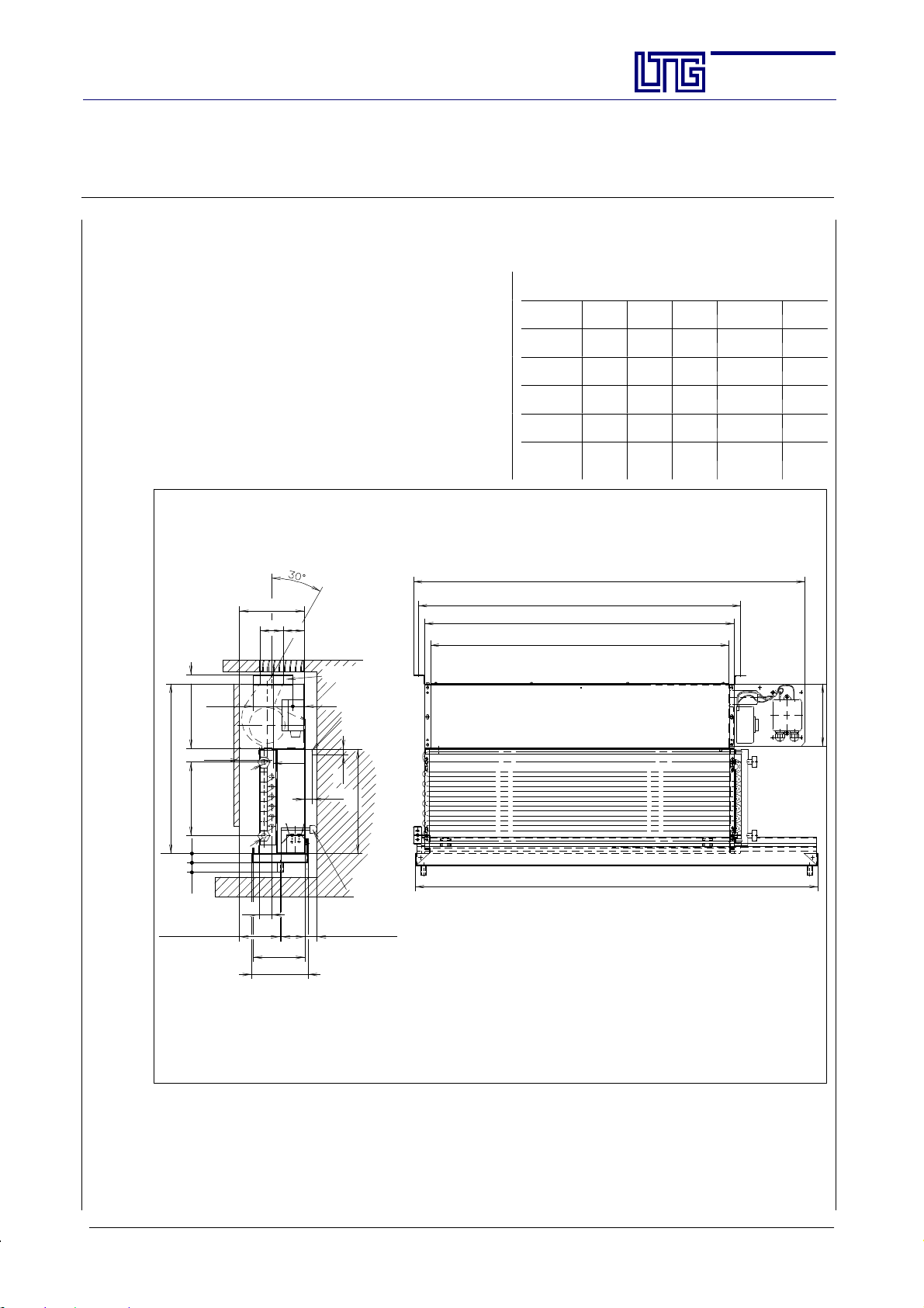
Unit for Sill Installation, 2-pipe System, for extremely low inlet temperatures
Specification
Fan coil unit withone heat exchanger for heating orcooling the ambient air.
Water-side control by valves.
Particularly small built--in depth and height, therefore
especially appropriate for a room-saving installation in
sills.
For extremelylow inlet temperatures an insulateddrain
tray is available for insertion on site.
Vertical installation.
Water connection on the right or left.
165
58 55
22
air outlet
Section:
Page:
Date:
AG--B 201.1e
16
Feb. 2010
Dimensions
Size A B C D E
500 527 497 563 757 755
630 627 597 663 857 855
800 857 827 893 1087 1085
1000 1057 1027 1093 1287 1285
1250 1257 1227 1293 1487 1485
total length, dimension E
unit suspension, dimension C
unit length, dimension A
air outlet, dimension B
suspension from
above -- special
100
165
50
431
187
25 25
condensate
drainage 102
Ø15
VL
RL
32
130
143
insulated
drain tray
80
60
version
30
standard:
bracket for rear
wall installation
(accessory)
15
18
266
rubber stop to be ordered
separately acc. to wallclearance
min. 15
without rear suspension
length of drain tray, dimension D
note: drain tray length may exceed
total length of unit.
RL = water return
VL = water inlet
The unit may be mounted using one of the following possibilities:
- suspension from above (attachment to the sill)
- wall mounting -- rear suspension
power
switch
160
E LTG Aktiengesellschaft ⋅ Grenzstraße 7 ⋅ D-70435 Stuttgart ⋅ +49 (0711) 8201-0 ⋅ Fax -720
Internet: http://www.LTG-AG.de ⋅ E-Mail: [email protected] ⋅ Printed in Germany ⋅ Ausgaben mit früherem
Datum werden hiermit ungültig ⋅ Technische Änderungen vorbehalten ⋅ Former editions are invalid ⋅ Subject to technical modifications.
Page 17
The Innovation Company
LTG Aktiengesellschaft
Instructions for Installation, Use and Maintenance
Fan Coil Unit Type VFC
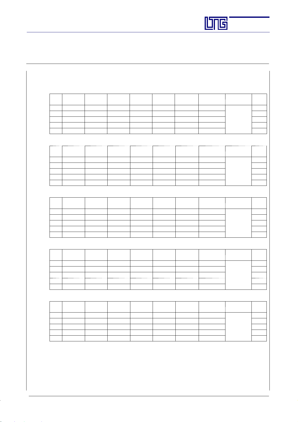
Technical Specifications, Unit for Sill Installation, 2-pipe System (legend see page 20)
Size 500
n
[-]V[m
3
/h]
L
A18
[dB(A)]
L
wA
[dB(A)]
Q
I 160 26 32 37 36 864 720
II 240 30 36 49 48 1152 960 20
III 290 36 42 57 56 1265 1120 23
IV 340 40 46 64 64 1408 1280 25
V 430 46 52 73 73 1576 1460 31
Size 630
n
[-]V[m
3
/h]
I 170 25 31 48 43 1032 860
II 260 29 35 59 59 1416 1180 20
III 310 35 41 68 68 1536 1360 23
IV 370 39 45 76 76 1672 1520 25
V 480 46 52 87 87 1879 1740 31
L
A18
[dB(A)]
L
wA
[dB(A)]
Q
koF
[W/K]
koF
[W/K]
/t
/t
1
Q
1
Q
kmF
[W/K]
kmF
[W/K]
/t
/t
Section:
Page:
Date:
1
2
Q
k
[W]
mF
Q
ksens
[W]
mF
2
[kg/h]/[kPa]
AG--B 201.1e
17
Feb. 2010
wo/p
P
w
[W]
el
16
200/18
1
2
Q
k
[W]
mF
Q
ksens
[W]
mF
2
wo/p
w
[kg/h]/[kPa]
P
[W]
el
16
200/20
Size 800
n
[-]V[m
L
3
/h]
A18
[dB(A)]
L
wA
[dB(A)]
Q
koF
[W/K]
/t
1
Q
I 220 25 31 52 48 1152 960
II 320 28 34 72 64 1536 1280 20
III 380 34 40 83 78 1762 1560 23
IV 460 38 44 95 92 2024 1840 25
V 580 45 51 105 105 2268 2100 31
kmF
[W/K]
/t
1
2
Q
k
[W]
mF
Q
ksens
[W]
mF
2
wo/p
w
[kg/h]/[kPa]
200/22
Size 1000
n
[-]V[m
L
3
/h]
A18
[dB(A)]
L
wA
[dB(A)]
Q
koF
[W/K]
/t
1
Q
I 300 27 33 62 59 1488 1180
II 420 30 36 82 76 1968 1520 29
III 470 34 40 92 89 2079 1780 33
IV 570 38 44 104 102 2288 2040 36
V 720 46 52 114 114 2462 2280 42
kmF
[W/K]
/t
1
2
Q
k
[W]
mF
Q
ksens
[W]
mF
2
wo/p
w
[kg/h]/[kPa]
200/23
Size 1250
n
[-]V[m
L
3
/h]
A18
[dB(A)]
L
wA
[dB(A)]
Q
koF
[W/K]
/t
1
Q
I 360 27 33 80 73 1752 1460
II 470 30 36 98 92 2208 1840 29
III 570 35 41 107 104 2350 2080 33
IV 690 38 44 116 113 2486 2260 36
V 830 46 52 128 124 2678 2480 42
1
) Specific cooling capacity (noncondensing operation)
2
) Cooling capacity with the following parameters: water inlet: 6_C,
kmF
[W/K]
/t
1
2
Q
k
[W]
mF
Q
ksens
[W]
mF
2
wo/p
w
[kg/h]/[kPa]
200/25
induction air temperature before entering the heat exchanger: 26_C, 50% rel. humidity
P
[W]
176
P
[W]
25
P
[W]
25
el
el
el
E LTG Aktiengesellschaft ⋅ Grenzstraße 7 ⋅ D-70435 Stuttgart ⋅ +49 (0711) 8201-0 ⋅ Fax -720
Internet: http://www.LTG-AG.de ⋅ E-Mail: [email protected] ⋅ Printed in Germany ⋅ Ausgaben mit früherem
Datum werden hiermit ungültig ⋅ Technische Änderungen vorbehalten ⋅ Former editions are invalid ⋅ Subject to technical modifications.
Page 18
The Innovation Company
LTG Aktiengesellschaft
Instructions for Installation, Use and Maintenance
Fan Coil Unit Type VFC
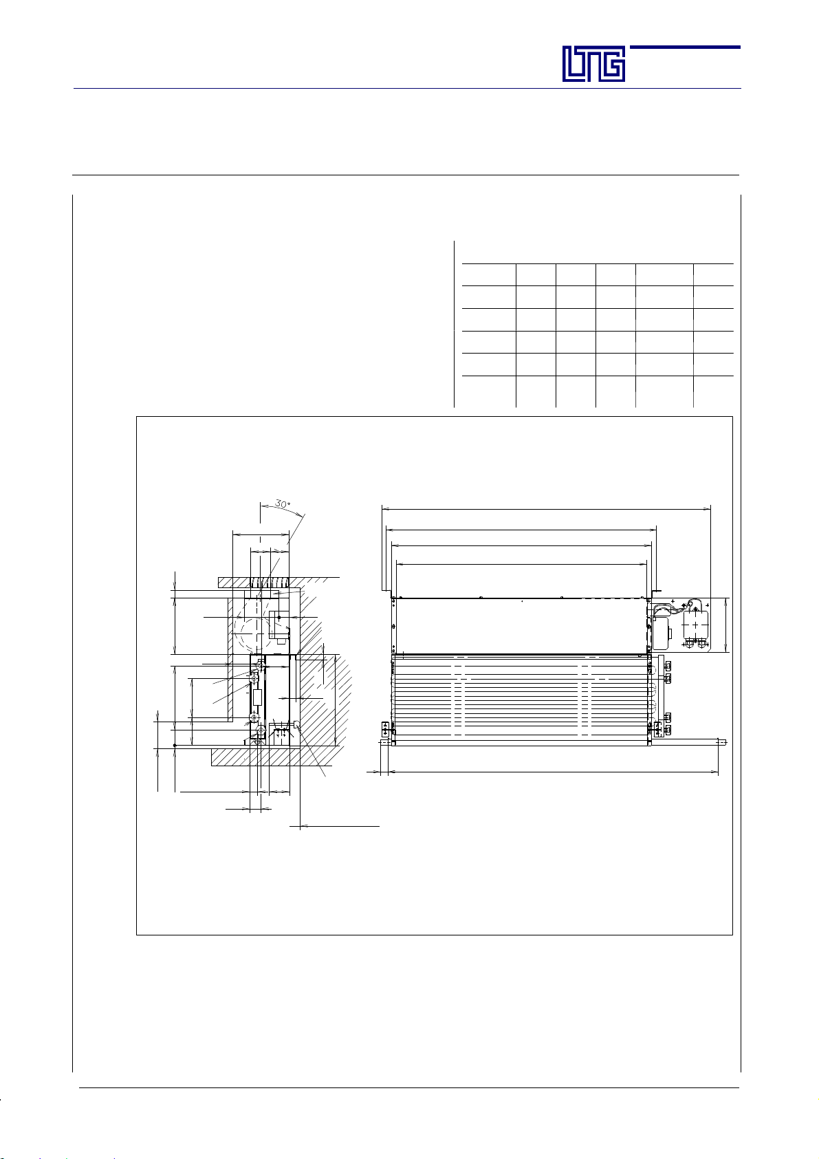
Unit for Sill Installation, 4-pipe System
Specifikation
Fan coil unit with one heat exchangerwith two separate
water cycles for heating and cooling the ambient air.
Water-side control by valves.
Particularly small built-in depth and height, therefore
especially appropriate for a room-saving installation in
For extremely low inlet temperatures the unit is available with an insulated drain tray.
Vertical installation.
Water connection on the right or left.
165
58
55
22
air outlet
Section:
Page:
Date:
AG--B 201.1e
18
Feb. 2010
Dimensions
Size A B C D E
500 527 497 563 730 755
630 627 597 663 885 855
800 857 827 893 1085 1085
1000 1057 1027 1093 1335 1285
1250 1257 1227 1293 1553 1485
total length, dimension E
unit suspension, dimension C
unit length, dimension A
air outlet, dimension B
suspension from
above -- special
version
30
standard: bracket
for rear wall installation (accessory)
15
18
266
25
rubber stop to be ordered
separately acc. to wallclearance
min. 10
without rear suspension
length of drain tray, dimension D
note: drain tray length may exceed
total length of unit.
KKW--VL = cooling -- water inlet
KKW--RL = cooling -- water return
HZG--VL = heating -- water inlet
HZG--RL = heating -- water return
min. 80
165
KKW- RL
113
187
HZG- RL
82
45
condensate
drainage 22
min. 10
Ø15
100
50
HZG-VL
KKW-VL
80
60
32
The unit may be mounted using one of the following possibilities:
- suspension from above (attachment to the sill)
- wall mounting -- rear suspension
160
E LTG Aktiengesellschaft ⋅ Grenzstraße 7 ⋅ D-70435 Stuttgart ⋅ +49 (0711) 8201-0 ⋅ Fax -720
Internet: http://www.LTG-AG.de ⋅ E-Mail: [email protected] ⋅ Printed in Germany ⋅ Ausgaben mit früherem
Datum werden hiermit ungültig ⋅ Technische Änderungen vorbehalten ⋅ Former editions are invalid ⋅ Subject to technical modifications.
Page 19
The Innovation Company
LTG Aktiengesellschaft
Instructions for Installation, Use and Maintenance
Fan Coil Unit Type VFC
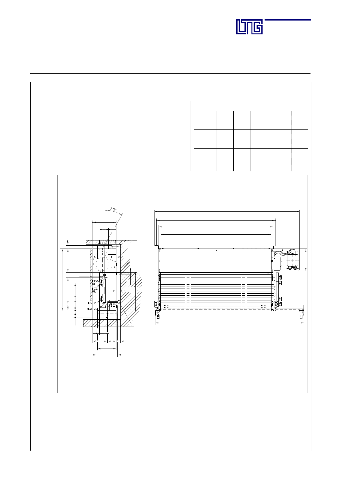
Unit for Sill Installation, 4-pipe System, for extremely low inlet temperatures
Specification
Fan coil unit with one heat exchanger and two separate
cycles for heating or cooling the ambient air.
Water-side control by valves.
Particularly small built-in depth and height, therefore especially appropriate for a room-saving installation in sills.
For extremelylow inlet temperatures an insulateddrain
tray is available for insertion on site.
Vertical installation.
Water connection on the right or left.
165
58 55
80
air outlet
suspension from
above -- special
version
30
standard:
bracket for rear
wall installation
(accessory)
15
18
266
22165187
100
50
431
113
Section:
Page:
Date:
AG--B 201.1e
19
Feb. 2010
Dimensions
Size A B C D E
500 527 497 563 757 755
630 627 597 663 857 855
800 857 827 893 1087 1085
1000 1057 1027 1093 1287 1285
1250 1257 1227 1293 1487 1485
total length, dimensionE
unit suspension, dimension C
unit length, dimension A
air outlet, dimension B
power
switch
160
82
2525
length of drain tray, dimension D
note:drain tray length mayexceed total length ofunit.
KKW--VL = cooling -- water inlet
KKW--RL = cooling -- water return
HZG--VL = heating -- water inlet
HZG--RL = heating -- water return
condensate
drainage 102
Ø15
32
insulated
drain tray
130
143
rubber stop to be ordered
separately acc. to wallclearance
60
min. 15
without rear suspension
The unit may be mounted using one of the following possibilities:
- suspension from above (attachment to the sill)
- wall mounting -- rear suspension
E LTG Aktiengesellschaft ⋅ Grenzstraße 7 ⋅ D-70435 Stuttgart ⋅ +49 (0711) 8201-0 ⋅ Fax -720
Internet: http://www.LTG-AG.de ⋅ E-Mail: [email protected] ⋅ Printed in Germany ⋅ Ausgaben mit früherem
Datum werden hiermit ungültig ⋅ Technische Änderungen vorbehalten ⋅ Former editions are invalid ⋅ Subject to technical modifications.
Page 20
The Innovation Company
LTG Aktiengesellschaft
Instructions for Installation, Use and Maintenance
Fan Coil Unit Type VFC
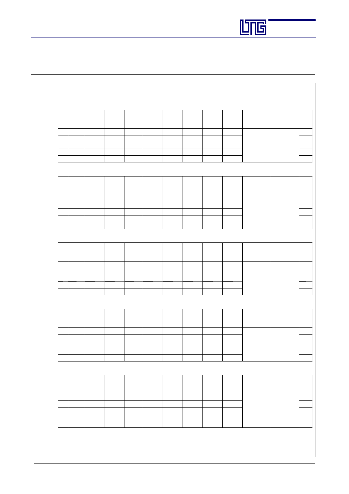
Technical Specifications, Unit for Sill Installation, 4-pipe System (legend see page 20)
Size 500
n
[-]V[m3/h]
L
A18
[dB(A)]
L
wA
[dB(A)]
Q
koF
t
[W/K]
/
Q
/t
mF
[W/K]
k
1
1
I 160 26 32 34 28 672 560 21 19
II 240 30 36 46 45 1080 900 28 28 20
III 290 36 42 54 54 1220 1080 32 32 23
IV 340 40 46 60 60 1320 1200 35 35 25
V 430 46 52 68 68 1468 1360 40 40 31
Size 630
n
[-]V[m3/h]
I 170 25 31 41 36 864 720 26 23
II 260 29 35 52 51 1224 1020 32 31 20
III 310 35 41 60 60 1356 1200 35 35 23
IV 370 39 45 67 67 1474 1340 39 39 25
V 480 46 52 76 76 1641 1520 43 43 31
L
A18
[dB(A)]
L
wA
[dB(A)]
Q
koF
t
[W/K]
/
Q
/t
mF
[W/K]
k
1
1
2
Q
mF
k
[W]
2
Q
mF
k
[W]
Q
mF
Q
mF
ksens
2
[W]
ksens
2
[W]
Q
hoF
t
[W/K]
Q
hoF
t
[W/K]
Section:
Page:
Date:
/
Q
hmF
t
[W/K]
/
Q
hmF
t
[W/K]
AG--B 201.1e
20
Feb. 2010
/
wok/p
w
[kg/h]/[kPa]
200 / 13 100 / 2.5
/
wok/p
w
[kg/h]/[kPa]
200 / 14 100 / 2.7
woh/p
[kg/h]/[kPa]
woh/p
[kg/h]/[kPa]
P
w
el
[W]
16
P
w
el
[W]
16
Size 800
n
[-]V[m3/h]
L
A18
[dB(A)]
L
wA
[dB(A)]
Q
koF
t
[W/K]
/
Q
/t
mF
[W/K]
k
1
1
I 220 25 31 47 42 1008 840 29 26
II 320 28 34 64 60 1440 1200 38 36 20
III 380 34 40 74 71 1604 1420 42 41 23
IV 460 38 44 82 81 1782 1620 47 47 25
V 580 45 51 92 91 1965 1820 51 51 31
2
Q
k
[W]
mF
Q
mF
ksens
2
[W]
Q
hoF
t
[W/K]
/
Q
/
hmF
wok/p
w
woh/p
w
t
[W/K]
[kg/h]/[kPa]
[kg/h]/[kPa]
200 / 16 100 / 3.1
Size 1000
n
[-]V[m3/h]
L
A18
[dB(A)]
L
wA
[dB(A)]
Q
koF
t
[W/K]
/
Q
/t
mF
[W/K]
k
1
1
I 300 27 33 58 53 1272 1060 36 33
II 420 30 36 76 71 1704 1420 47 44 29
III 470 34 40 85 82 1853 1640 54 51 33
IV 570 38 44 95 92 2024 1840 59 57 36
V 720 46 52 107 105 2268 2100 65 65 42
2
Q
k
[W]
mF
Q
mF
ksens
2
[W]
Q
hoF
t
[W/K]
/
Q
/
hmF
wok/p
w
woh/p
w
t
[W/K]
[kg/h]/[kPa]
[kg/h]/[kPa]
200 / 18 100 / 3.4
Size 1250
n
[-]V[m3/h]
L
A18
[dB(A)]
L
wA
[dB(A)]
Q
koF
t
[W/K]
/
Q
/t
mF
[W/K]
k
1
1
I 360 27 33 74 68 1632 1360 46 43
II 470 30 36 90 85 2040 1700 54 51 29
III 570 35 41 98 96 2196 1920 61 58 33
IV 690 38 44 106 104 2288 2080 63 61 36
V 830 46 52 118 116 2505 2320 69 67 42
1
) Specific cooling capacity (noncondensing operation)
2
) Cooling capacity with the following parameters: water inlet: 6_C,
2
Q
k
[W]
mF
Q
mF
ksens
2
[W]
Q
hoF
t
[W/K]
/
Q
/
hmF
wok/p
w
woh/p
w
t
[W/K]
[kg/h]/[kPa]
[kg/h]/[kPa]
200 / 20 100 / 3.6
induction air temperature before entering the heat exchanger: 26_C, 50% rel. humidity
P
[W]
16
P
[W]
25
P
[W]
25
el
el
el
E LTG Aktiengesellschaft ⋅ Grenzstraße 7 ⋅ D-70435 Stuttgart ⋅ +49 (0711) 8201-0 ⋅ Fax -720
Internet: http://www.LTG-AG.de ⋅ E-Mail: [email protected] ⋅ Printed in Germany ⋅ Ausgaben mit früherem
Datum werden hiermit ungültig ⋅ Technische Änderungen vorbehalten ⋅ Former editions are invalid ⋅ Subject to technical modifications.
Page 21
The Innovation Company
LTG Aktiengesellschaft
Instructions for Installation, Use and Maintenance
Fan Coil Unit Type VFC
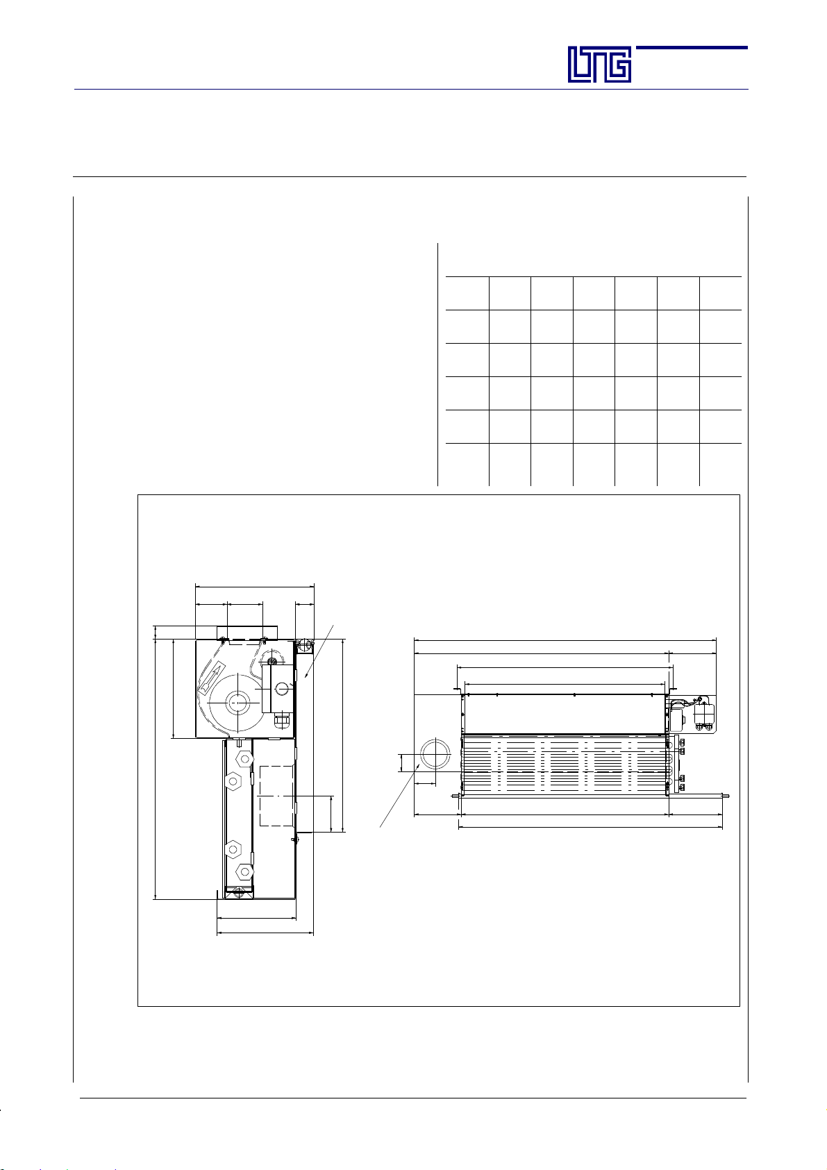
Unit for Sill Installation with Fresh Air Supply by Linear Diffuser LDB
Specification
Fan coil unit special version with fresh air supply.
Through an adjustable LTG diffuser type LDB, the
air is blown out in paralle l to the cross-flow fan
outlet.
Optimum fresh air supply is ensured even with the
fan at standstill.
Fan coil unit with one heat exchanger and two separate circuits for heating or cooling the ambient air.
Water-side control by valves.
Particularly small built-in depth and height, therefore especially appropriate for a room-saving installation in sills.
Vertical installation.
Water connection on the right or left.
Section:
Page:
Date:
AG--B 201.1e
21
Feb. 2010
Dimensions
Size A B C D E F
500 720 497 563 730 527 916
630 820 597 663 885 627 1016
800 1050 827 893 1085 857 1246
1000 1250 1027 1093 1335 1057 1446
1250 1450 1227 1293 1553 1257 1646
431 22
52 58 31
165
196
130
160
LDB 20/8/1
320
60
total length,dimension F
air distribution box, dimension A
unit su sp e nsion, dimension C
air outlet, dimension B
71
86
193
Connection fresh air
size 500 and size 630: DN 100
size 800, 1000 and 1250: DN 125
unit length, dimension E
drain tray, dimension D
Lateral view shown reduced
196
221
shown: 4-pipe- unit
Technical data see standard unit VFC--4/VFC--2
Acoustic data may vary according to fresh air rate.
E LTG Aktiengesellschaft ⋅ Grenzstraße 7 ⋅ D-70435 Stuttgart ⋅ +49 (0711) 8201-0 ⋅ Fax -720
Internet: http://www.LTG-AG.de ⋅ E-Mail: [email protected] ⋅ Printed in Germany ⋅ Ausgaben mit früherem
Datum werden hiermit ungültig ⋅ Technische Änderungen vorbehalten ⋅ Former editions are invalid ⋅ Subject to technical modifications.
Page 22
The Innovation Company
LTG Aktiengesellschaft
Instructions for Installation, Use and Maintenance
Fan Coil Unit Type VFC
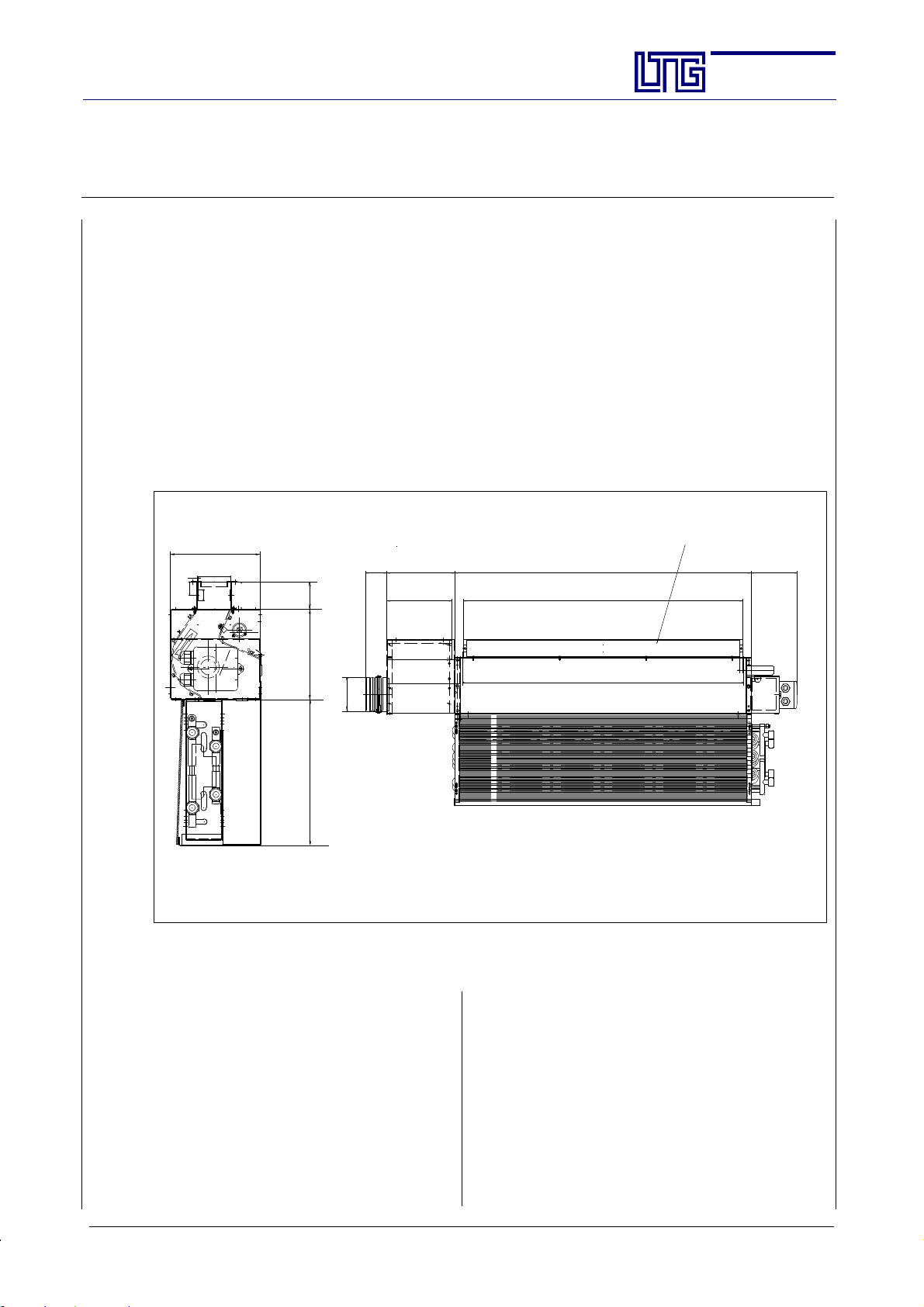
Unit for Sill Installation with Fresh Air Supply by Fresh Air Box
Fan coil uni t special version with fresh air supply, with lateral (left, opposite to m otor) primary air box in extension to the recirculating air outlet
Connection is realized using a DN 100 socket, with integrated damper (option).
Optimum fresh air supply is ensured even with the fan at standstill.
Fan coil unit with one heat exchanger and two separate circuits for heating or cooling the ambient air.
Water-side control by valves.
Particularly small built-in depth and height, therefore especially appropriate for a room-saving installation
in sills.
Vertical installation.
Water connection on the right or left.
Socket (option) to adapt to local air outlet requirements
165
62
21
50
188
Section:
Page:
Date:
857 134197
810
AG--B 201.1e
22
Feb. 2010
165
Ø99
267
Type VFC (shown: 4-pipe) with fresh air supply by fresh air box
10 10
7
Technical data see standard unit VFC--4/VFC--2
Acoustic data may vary according to fresh air rate.
Legend to the Technical Specification
n -- speed
V --flow rate (
L
A18
L
wA
--sound pressure level , 18 m2Sabine
--sound power level ¦ 3dB(A)
(without casing)
Q
Q
Q
Q
-- cooling capacity (without filter)
koF
-- cooling capacity (with filter)
kmF
--heating capacity (without filter)
hoF
-- heating capacity (with filter)
hmF
¦ 10%)
Q
ksensmF--
t --temperature difference between induction
w
ok
w
oh
p
P
el
812
Lateral view shown reduced
sensible cooling capacity (with filter)
air temp. before enteringthe heat exchanger
and water supply
-- standard water flow rate at cooling capacity
-- standard water flow rate at heating capacity
w
-- water--side pressure loss
--electric power consumption (¦ 20%)
E LTG Aktiengesellschaft ⋅ Grenzstraße 7 ⋅ D-70435 Stuttgart ⋅ +49 (0711) 8201-0 ⋅ Fax -720
Internet: http://www.LTG-AG.de ⋅ E-Mail: [email protected] ⋅ Printed in Germany ⋅ Ausgaben mit früherem
Datum werden hiermit ungültig ⋅ Technische Änderungen vorbehalten ⋅ Former editions are invalid ⋅ Subject to technical modifications.
Page 23
The Innovation Company
LTG Aktiengesellschaft
Instructions for Installation, Use and Maintenance
Fan Coil Unit Type VFC
Technical Specifications, Units for Sill Installation with Fresh Air Supply
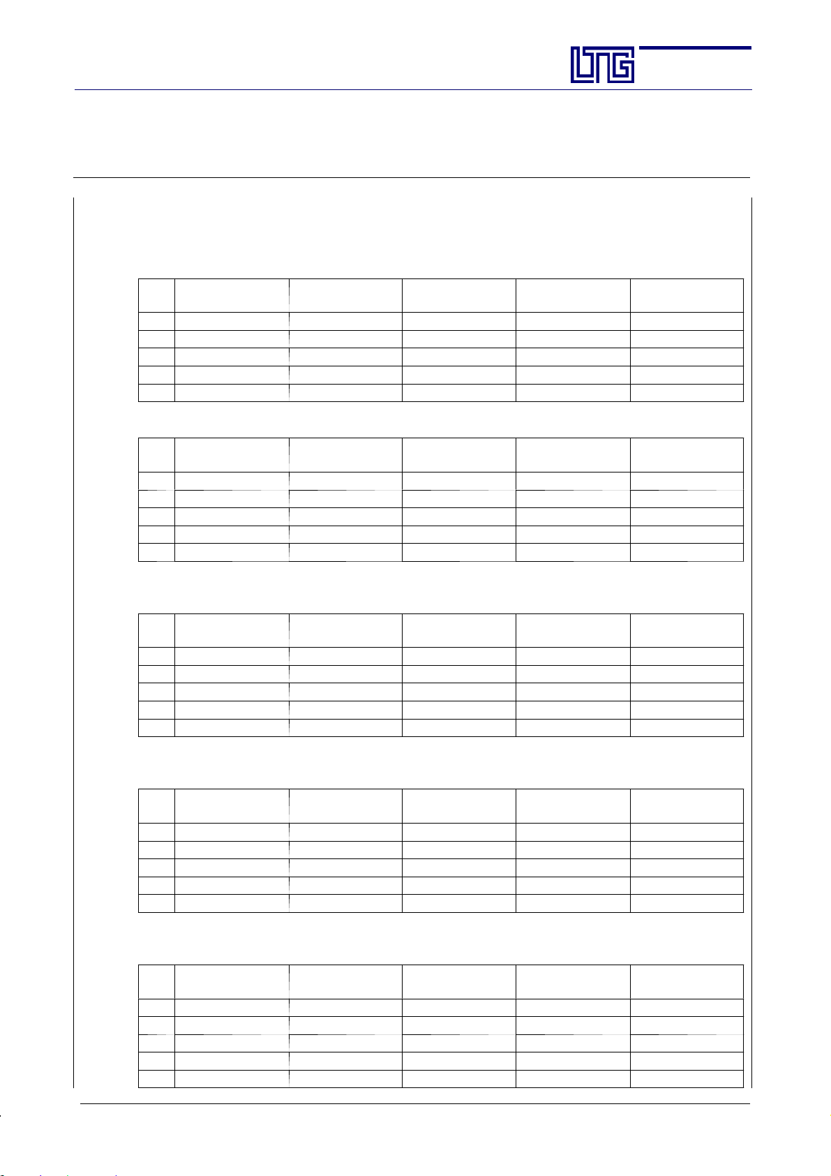
Sound Power Values with Fresh Air
Sound power LwAfor size 500 with fresh air, connection Ø 100 mm
n
VP=30m3/h
[-]
[dB(A)]
I 34 31 34 37 41
II 37 35 37 38 41
III 42 41 41 41 44
IV 45 44 44 44 45
V 52 51 51 51 51
Sound power LwAfor size 630 with fresh air, connection Ø 100 mm
n
VP=40m3/h
[-]
[dB(A)]
I 32 32 35 38 41
II 35 34 36 38 41
III 42 40 40 41 44
IV 46 44 44 44 45
V 52 51 51 51 51
VP=40m3/h
[dB(A)]
VP=50m3/h
[dB(A)]
VP=50m3/h
VP=60m3/h
[dB(A)]
[dB(A)]
Section:
Page:
Date:
VP=60m3/h
[dB(A)]
VP=70m3/h
[dB(A)]
AG--B 201.1e
23
Feb. 2010
VP=70m3/h
[dB(A)]
VP=80m3/h
[dB(A)]
Sound power LwAfor size 800 with fresh air, connection Ø 125 mm
(fresh air box: Ø 100 mm)
n
[-]
VP=60m3/h
[dB(A)]
VP=70m3/h
[dB(A)]
VP=80m3/h
[dB(A)]
VP=90m3/h
[dB(A)]
VP= 100 m3/h
I 32 33 35 38 40
II 36 35 36 38 40
III 41 39 40 41 42
IV 44 43 43 43 44
V 52 51 51 51 51
Sound power LwAfor size 1000 with fresh air, connection Ø 125 mm
(fresh air box: Ø 100 mm)
n
[-]
VP=70m3/h
[dB(A)]
VP=80m3/h
[dB(A)]
VP=90m3/h
[dB(A)]
VP= 100 m3/h
[dB(A)]
VP= 120 m3/h
I 33 34 34 37 41
II 36 35 37 38 41
III 41 39 39 40 42
IV 45 43 43 43 44
V 52 51 51 51 51
Sound power LwAfor size 1250 with fresh air, connection Ø 125 mm
(fresh air box: Ø 100 mm)
n
[-]
VP=80m3/h
[dB(A)]
VP=90m3/h
[dB(A)]
VP= 100 m3/h
[dB(A)]
VP= 120 m3/h
[dB(A)]
VP= 140 m3/h
I 33 34 35 36 38
II 36 35 37 38 38
III 41 39 39 40 42
IV 45 43 43 43 44
V 52 50 50 50 50
[dB(A)]
[dB(A)]
[dB(A)]
E LTG Aktiengesellschaft ⋅ Grenzstraße 7 ⋅ D-70435 Stuttgart ⋅ +49 (0711) 8201-0 ⋅ Fax -720
Internet: http://www.LTG-AG.de ⋅ E-Mail: [email protected] ⋅ Printed in Germany ⋅ Ausgaben mit früherem
Datum werden hiermit ungültig ⋅ Technische Änderungen vorbehalten ⋅ Former editions are invalid ⋅ Subject to technical modifications.
Page 24
The Innovation Company
LTG Aktiengesellschaft
Instructions for Installation, Use and Maintenance
Fan Coil Unit Type VFC
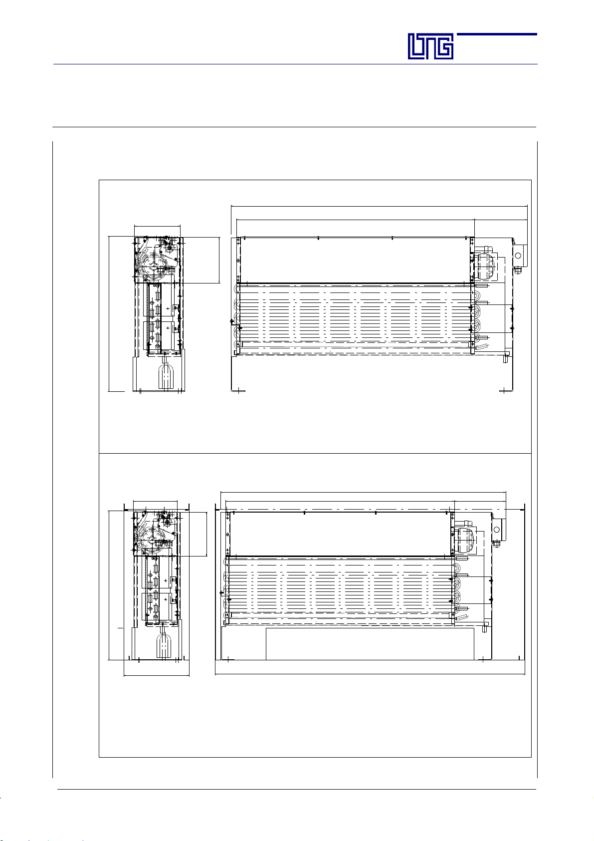
Upright Unit with solid Floor Fixation
165
165
559
1067
Section:
Page:
Date:
AG--B 201.1e
24
Feb. 2010
191857
Type VFC 800 (shown: 4- pipe), upright unit with solid floor fixation
without casing
857 191165
165
559
(246)
(1160)
1067
Type VFC 800 (shown: 4- pipe), upright unit with solid floor fixation
with casing
Technical data see standard unit VFC--4/VFC--2
E LTG Aktiengesellschaft ⋅ Grenzstraße 7 ⋅ D-70435 Stuttgart ⋅ +49 (0711) 8201-0 ⋅ Fax -720
Internet: http://www.LTG-AG.de ⋅ E-Mail: [email protected] ⋅ Printed in Germany ⋅ Ausgaben mit früherem
Datum werden hiermit ungültig ⋅ Technische Änderungen vorbehalten ⋅ Former editions are invalid ⋅ Subject to technical modifications.
Page 25
The Innovation Company
LTG Aktiengesellschaft
Instructions for Installation, Use and Maintenance
Fan Coil Unit Type VFC
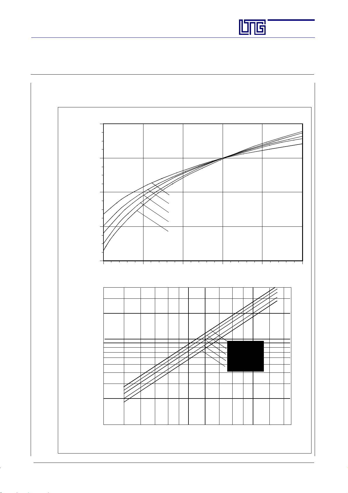
Water-side Pressure Loss and Capacity for different Flow Rates,
2-pipe System
120
100
80
60
I
II
III Speed
IV
V
Section:
Page:
Date:
AG--B 201.1e
25
Feb. 2010
Capacity in % of the nom. capacity Q
40
50 100 150 200 250 300
Flow rate w [kg/h]
40
20
[kPa]
10
w
5
3
2
VFC 1250
VFC 1000
VFC 800
VFC 630
VFC 500
Water--side pressure loss p
1
50 70 100 200140 280
Flow rate w [kg/h]
E LTG Aktiengesellschaft ⋅ Grenzstraße 7 ⋅ D-70435 Stuttgart ⋅ +49 (0711) 8201-0 ⋅ Fax -720
Internet: http://www.LTG-AG.de ⋅ E-Mail: [email protected] ⋅ Printed in Germany ⋅ Ausgaben mit früherem
Datum werden hiermit ungültig ⋅ Technische Änderungen vorbehalten ⋅ Former editions are invalid ⋅ Subject to technical modifications.
Page 26
The Innovation Company
LTG Aktiengesellschaft
Instructions for Installation, Use and Maintenance
Fan Coil Unit Type VFC
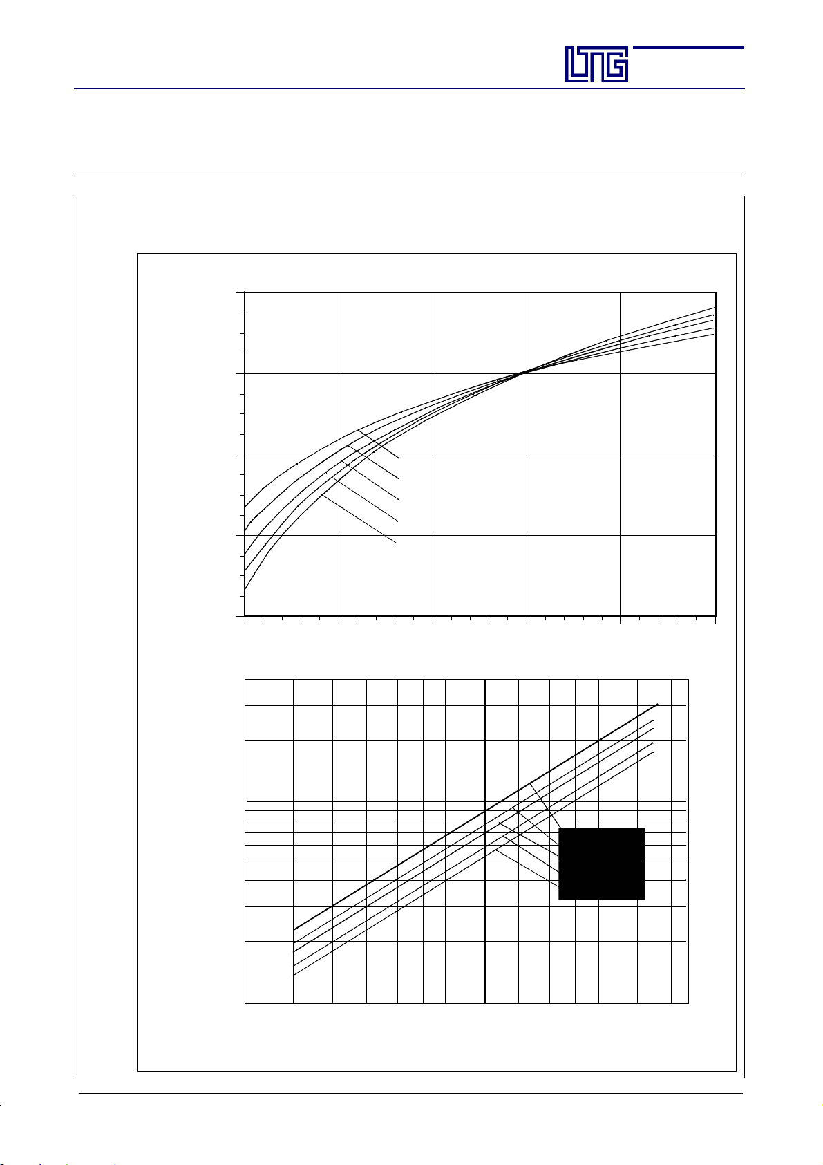
Water-side Pressure Loss and Cooling Capacity for different Flow Rates,
4-pipe System
120
k
100
80
60
I
II
III Speed
IV
V
Section:
Page:
Date:
AG--B 201.1e
26
Feb. 2010
Cooling capacity in % of the nom. c apacity Q
40
50 100 150 200 250 300
Flow rate w [kg/h]
40
20
[kPa]
10
w
VFC 1250
5
3
2
VFC 1000
VFC 800
VFC 630
VFC 500
Water--side pressure loss p
1
50 70 100 200140 280
Flow rate w [kg/h]
E LTG Aktiengesellschaft ⋅ Grenzstraße 7 ⋅ D-70435 Stuttgart ⋅ +49 (0711) 8201-0 ⋅ Fax -720
Internet: http://www.LTG-AG.de ⋅ E-Mail: [email protected] ⋅ Printed in Germany ⋅ Ausgaben mit früherem
Datum werden hiermit ungültig ⋅ Technische Änderungen vorbehalten ⋅ Former editions are invalid ⋅ Subject to technical modifications.
Page 27
The Innovation Company
LTG Aktiengesellschaft
Instructions for Installation, Use and Maintenance
Fan Coil Unit Type VFC
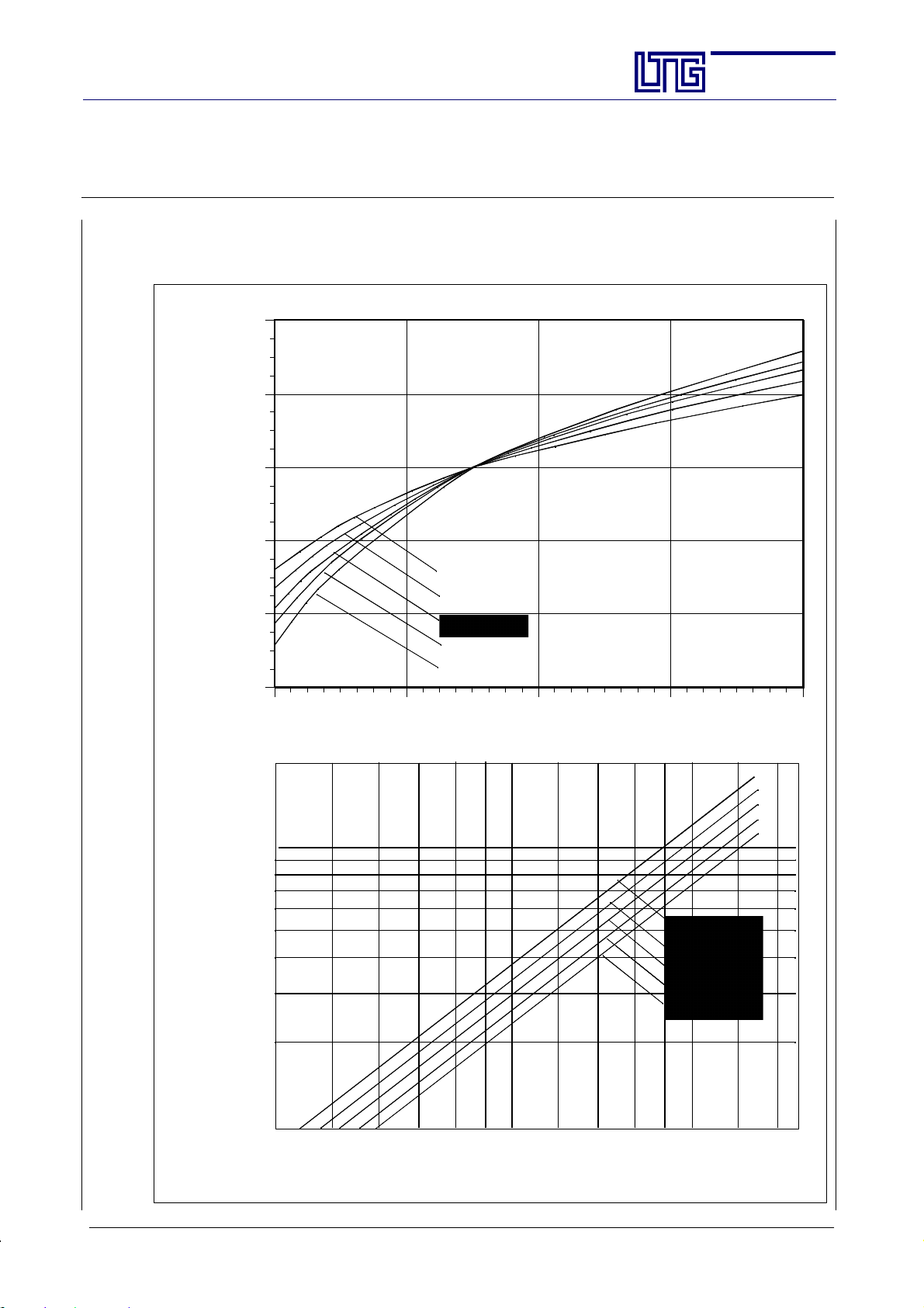
Water-side Pressure Loss and Heating Capacity for different Flow Rates,
4-pipe System
140
h
120
100
80
I
60
Heatling capacity in % of the nom. capacity Q
40
II
III Speed
IV
V
Section:
Page:
Date:
AG--B 201.1e
27
Feb. 2010
40 80 120 160 200
Flow rate w [kg/h]
20
10
[kPa]
w
5
3
2
VFC 1250
VFC 1000
VFC 800
VFC 630
VFC 500
Water--side pressure loss p
1
50 70 100 200140 280
Flow rate w [kg/h]
E LTG Aktiengesellschaft ⋅ Grenzstraße 7 ⋅ D-70435 Stuttgart ⋅ +49 (0711) 8201-0 ⋅ Fax -720
Internet: http://www.LTG-AG.de ⋅ E-Mail: [email protected] ⋅ Printed in Germany ⋅ Ausgaben mit früherem
Datum werden hiermit ungültig ⋅ Technische Änderungen vorbehalten ⋅ Former editions are invalid ⋅ Subject to technical modifications.
Page 28
The Innovation Company
LTG Aktiengesellschaft
Instructions for Installation, Use and Maintenance
Fan Coil Unit Type VFC
3.2 Caloric Output Data
Caloric output data were determined at a test stand in the LTG test lab.
Data are valid if the following applies:
- unit at operating temperature, steady--state condition
- steady--state condition during measurements
- no condensation at the heat exchanger in the cooling mode
- water without additives (drinking water quality)*
- water supply temperatures from 12 _Cto16_C in the cooling mode and 50 _C--60_Cin the heating mode.
Parameters used:
- specific hea t capacity of the water 4186 J/(kgK)
- specific hea t capacity of the air 1004 J/(kgK)
- air density 1.2 kg/m
To ensure easy transferability, the specific caloric outputs -- i.e. the absolute caloric outputs in relation to the
temperature difference between water intake and induction air before entering the heat exchanger -- are given
with varying fan speeds.
The outputs given in the chart do apply with specific nominal flow rates only. These are stated for each type
and size.
The correction charts give a graphic illustration of how outputs change with otherflow rates compared to nominal flow rate output.
Flow rates have been determined through calculation and may vary by about 10%.
* Addition of ethylene glycol to lower the freezing point:
To lowerthe freezingpoint, coolingwater isoften addedsome ethyleneglycol. The lowerspecific thermal
capacity of the mixture reduces the unit’s cooling capacity.
3
Section:
Page:
Date:
AG--B 201.1e
28
Feb. 2010
3.3 Acoustic Data
Acoustic data have been determined in a reverberation chamber in the LTG test lab.
The technical data sheet contain the A weighted sound pressure levels L
Sound pressure levels a pply to a room absorption surface of 18 m
6 dB(A). Thus, sound power levels may easily be calculated.
L
WA=LA18
+ 6 dB(A)
The da ta given apply to one unit, i.e. one room axle. If more than one unit is installed in the same room, the
sound pressure level will rise accordingly.
Increase in sound level with several sound sources of the same type:
Number of sound sources of the same type
Sound level increase [dB] 3 5 6
Measuring accuracy is 10%.
3.4 Hydraulic Data
Heat exchangers are approved for an operating pressure of 10 bar max. (test pressure 16 bar).
Pressures exceeding 10 bar require the express permission of LTG.
Water--side pressure losses have been measured directly at the heat exchanger connections. Further resistances will have to be added.
Measuring accuracy is 10%.
A18
2
which equals a room absorption of about
1 2 3 4
for different fan speedss.
E LTG Aktiengesellschaft ⋅ Grenzstraße 7 ⋅ D-70435 Stuttgart ⋅ +49 (0711) 8201-0 ⋅ Fax -720
Internet: http://www.LTG-AG.de ⋅ E-Mail: [email protected] ⋅ Printed in Germany ⋅ Ausgaben mit früherem
Datum werden hiermit ungültig ⋅ Technische Änderungen vorbehalten ⋅ Former editions are invalid ⋅ Subject to technical modifications.
Page 29
The Innovation Company
LTG Aktiengesellschaft
Instructions for Installation, Use and Maintenance
Fan Coil Unit Type VFC
3.5 Weight
Weights (without packaging) in kg
Size
VFC 500
VFC 630
VFC 800
VFC 1000
VFC 1250
Unit for sill installation
13
15
19
23
28
3.6 Electrical Data
3.5.1 Electrical Connection
(on--site control)
Connect the unit to a residual current device (RCD).
Section:
Page:
Date:
AG--B 201.1e
29
Feb. 2010
Ceiling unit
Unit for sill installation with additional drain tray
15
18
23
28
33
All units are provided with a terminal box installed inside the unit, degree of protection IP 44.
A total of 5 units may be connected in parallel and triggeredthrough asingle
switch.
Take care to connect in parallel identical speeds only, i.e. connect speed I of
unit 1 to speed I of unit 2, etc.
For a safe start of the fans it is indispensable to use speed III.
The main power supply on site is to be performed according to the wiring diagram and by skilled and trained
staff only.
Electrical lines on site must be realized using the outputs on the terminal box and on the unit housing.
It is not permitted to work on the electrical equipment with the unit being alive.
Units must be provided with a possibility to completely disconnected them from
the main power supply!
Any work mustbe performed in compliance with national regulations and safety
instructions.
The technical specifications contain the electrica l output data for the units.
E LTG Aktiengesellschaft ⋅ Grenzstraße 7 ⋅ D-70435 Stuttgart ⋅ +49 (0711) 8201-0 ⋅ Fax -720
Internet: http://www.LTG-AG.de ⋅ E-Mail: [email protected] ⋅ Printed in Germany ⋅ Ausgaben mit früherem
Datum werden hiermit ungültig ⋅ Technische Änderungen vorbehalten ⋅ Former editions are invalid ⋅ Subject to technical modifications.
Page 30
The Innovation Company
LTG Aktiengesellschaft
Instructions for Installation, Use and Maintenance
Fan Coil Unit Type VFC
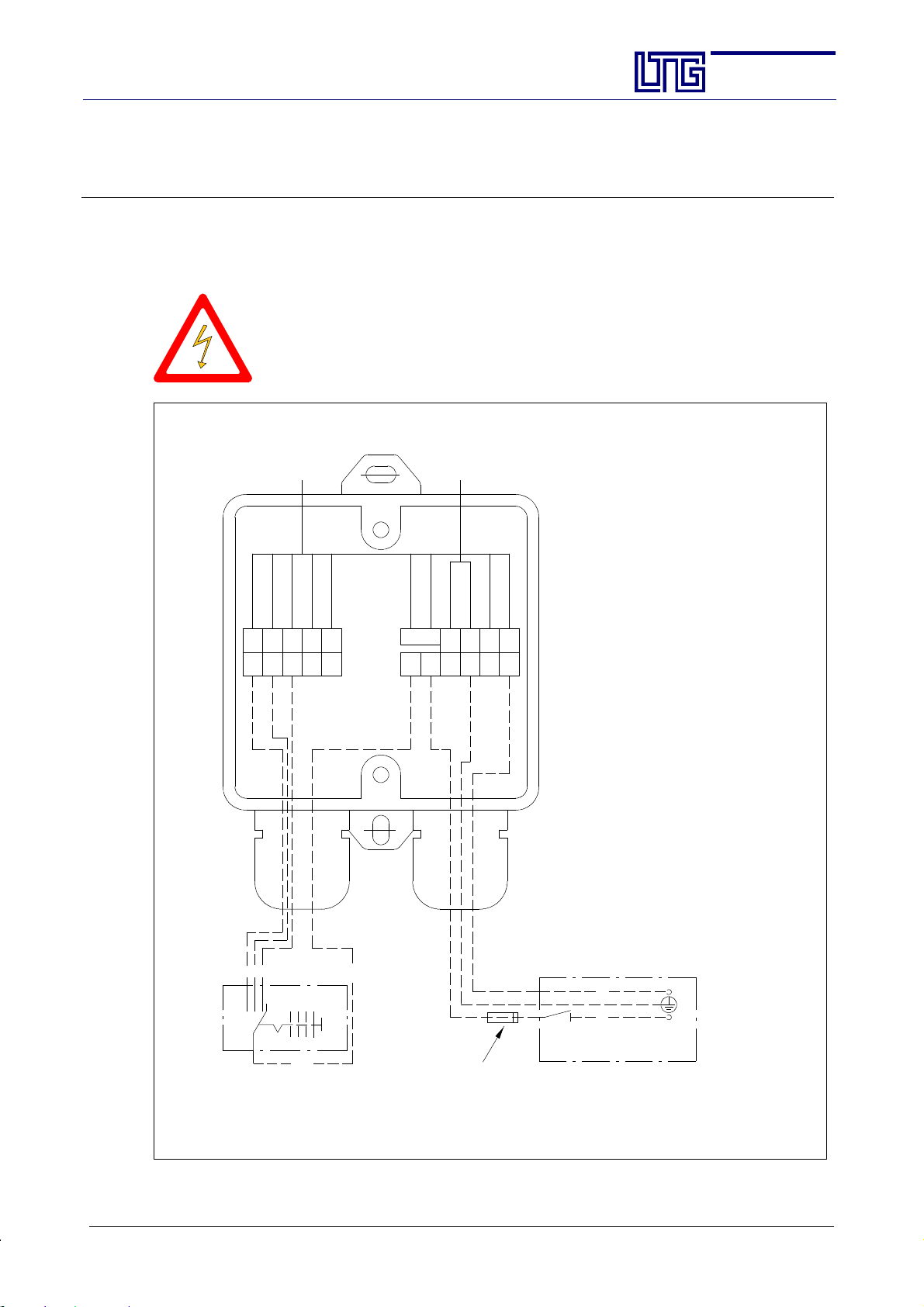
For an individual activation all units are equipped with a terminal box mounted to the unit.
A total of 5 units may be connected in parallel and triggered using a single switch.
Connection to the main power supply on site is to be performed according to the
wiring diagram and by skilled and trained staff only.
It is not permitted to work on the electrical equipment with the unit being alive.
Unitsmust be providedwith apossibility to completely disconnect them from the
main power supply.
It is not permitted to operate the units in a partly disassembled condition.
connection
side LTG
Section:
Page:
Date:
AG--B 201.1e
30
Feb. 2010
speed I
white
speed II
speed III
gray
red
speed IV
112233445
123
switch
1
L1
032
speed V
orange
5
1
S
black
yellow
brown
capacitor
C
LL PEN
PE N
L1
fuse 2A: slow-blow,
on site, can vary acc. to project
(see design data)
blue
yellow-green
CN
PE
Notice:
Forsafestartingofthefan,
use speed III
N
L
disconnector, on site
power supply
E LTG Aktiengesellschaft ⋅ Grenzstraße 7 ⋅ D-70435 Stuttgart ⋅ +49 (0711) 8201-0 ⋅ Fax -720
Internet: http://www.LTG-AG.de ⋅ E-Mail: [email protected] ⋅ Printed in Germany ⋅ Ausgaben mit früherem
Datum werden hiermit ungültig ⋅ Technische Änderungen vorbehalten ⋅ Former editions are invalid ⋅ Subject to technical modifications.
Page 31
The Innovation Company
LTG Aktiengesellschaft
Instructions for Installation, Use and Maintenance
Fan Coil Unit Type VFC
4. Installation
4.1 Installation / Suspension
There are, in general, three ways to install or suspend the units:
- wall mounting -- rear or lateral
- installation using floor stands
- ceiling installation
Please consider the following when installing the units:
- To ensure unit stability and rigidity, use screws of at least the stated property class when fixing the unit.
Fixings required for installation are not included.
- Use only the existing holes on the unit for the fixing elements.
- Use only the fixing ele ments described on the following pages for fixing the unit to ensure sufficient stability. Always observe the installation instructions!
- Do not use t he air conditioning units as supporting elements for other components and avoid loading them
in any other way.
4.1.1 Ceiling Units
Units are installed using threaded rods M8 and the 4 brackets provided for on the unit.
Section:
Page:
Date:
AG--B 201.1e
31
Feb. 2010
The cooler must be angled by 10_ in order to allow the condensate drainage
and to avoid condensate between the blades of the heat exchanger (in case
of constant condensate formation).
4.1.2 Units for Sill Installation
There are various possibilities to install the units (see following 2 pages):
- Units are installed using the two angle brackets on the unit’s top and 4 bolts.
- Using an angle bracket on the unit’s backside, the unit ma y be fixed to a wall or floor support.
Additionally, the unit may be secured against the wall using rubber stops.
Select fittings in a way to ensure that sound transmission is avoided.
E LTG Aktiengesellschaft ⋅ Grenzstraße 7 ⋅ D-70435 Stuttgart ⋅ +49 (0711) 8201-0 ⋅ Fax -720
Internet: http://www.LTG-AG.de ⋅ E-Mail: [email protected] ⋅ Printed in Germany ⋅ Ausgaben mit früherem
Datum werden hiermit ungültig ⋅ Technische Änderungen vorbehalten ⋅ Former editions are invalid ⋅ Subject to technical modifications.
Page 32
The Innovation Company
LTG Aktiengesellschaft
Instructions for Installation, Use and Maintenance
Fan Coil Unit Type VFC
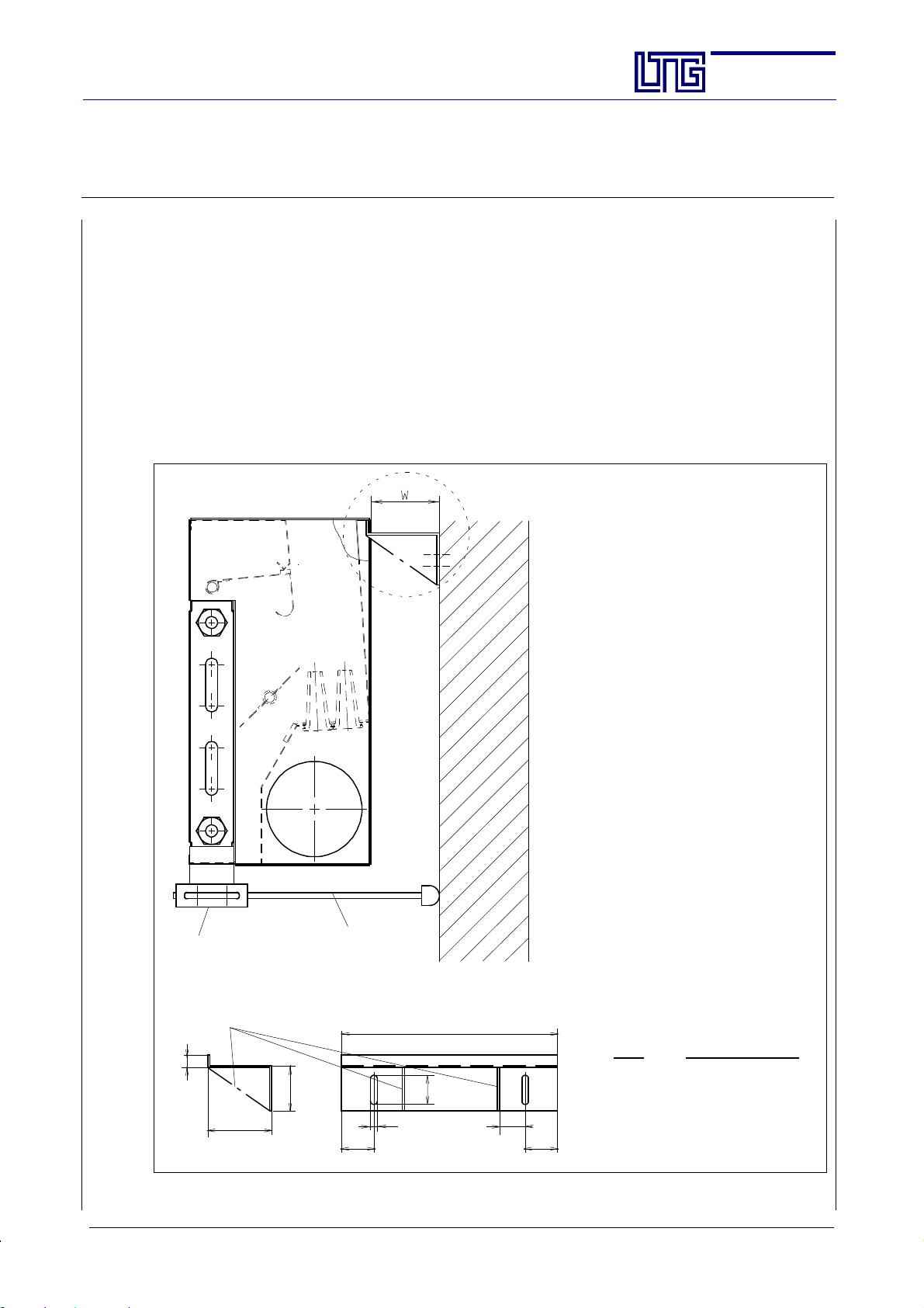
Wall mounting - Rear Suspension
For rear suspension, a Z profile is available. It offers the possibility to subsequently adjust the unit in height
by approx. 10 mm and lateral ly, parallel to the wall, by approx. 50 mm.
However, the wall clearance cannot be adjusted. Therefore, always state the clearance W between the unit
and the wall in your order. Forstability reasons, this clearance must not exceed 200 mm when using the standard version, but for greater clearances, a reinforced version is available.
If the unit is not supported from below, use a spacer in addition to the wall bracket for safety reasons (consisting of clamping pieces or clamping brackets and rubber stops).
The unit housing can be supported in the same way on the front side
For wall mounting, screws of at least property class M8 (8.8) are to be used to ensure sufficient stability.
=15mm
W
min
X
Section:
Page:
Date:
AG--B 201.1e
32
Feb. 2010
50
rubber stop
wall bracket
60
12
24
B
ca. 50
60
L = W + 5 mm for version I
L = W + 55 mm for version II
Size Dimension B in mm
500 375
630 495
800 670
1000 870
1250 1110
clamping clip
gusset
X
only if L > 205 mm
15
L
E LTG Aktiengesellschaft ⋅ Grenzstraße 7 ⋅ D-70435 Stuttgart ⋅ +49 (0711) 8201-0 ⋅ Fax -720
Internet: http://www.LTG-AG.de ⋅ E-Mail: [email protected] ⋅ Printed in Germany ⋅ Ausgaben mit früherem
Datum werden hiermit ungültig ⋅ Technische Änderungen vorbehalten ⋅ Former editions are invalid ⋅ Subject to technical modifications.
Page 33
The Innovation Company
LTG Aktiengesellschaft
Instructions for Installation, Use and Maintenance
Fan Coil Unit Type VFC
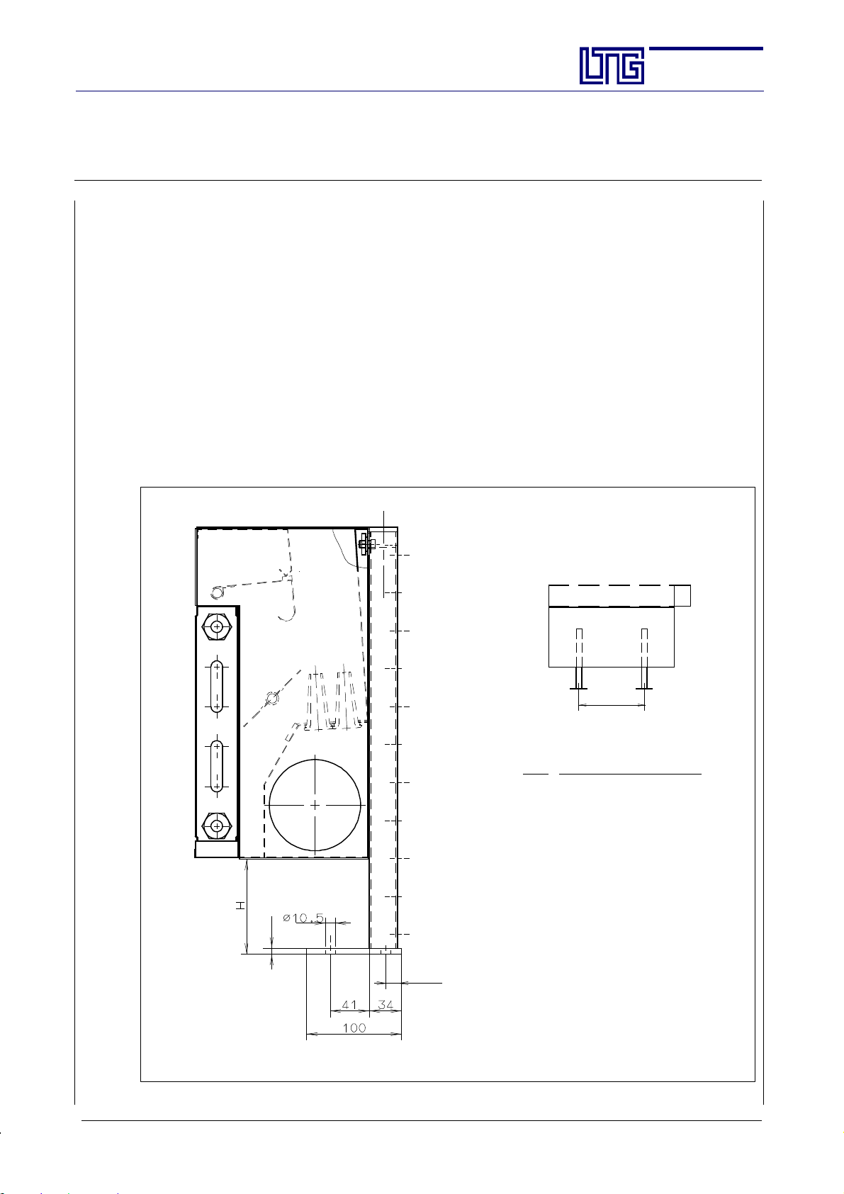
Installation using Floor Stands
For an installation independent of the wall, galvanized floor stands with a plastic plug are available (2 floor
stands required for each unit).
The floor stand height L depends on the unit type and the installation conditions. Dimension H > 20 mm may
be sufficient. Please always state the unit type and dimension ’H’ when ordering.
The unit is adjustable in height, upwards by approx. 5 mm, and downwards to ’H’.
However, it should be considered that the floor stand may exceed the unit height.
The unit may also be adjusted to the rear in the slots of the stand by approx. 10 mm.
The unit may furthermore be adjusted laterally, in its longitudinal axis, by approx. 50 mm, provided that the
center-to-center distance of the stands is observed.
Location screws (included i n the delivery) are fixed to the rails of the floor stands and the unit is inserted in
this fixing device.
When fixing the unit to the floor, use screws of at least property class M8 (8.8). These special screws are not
included in the delivery.
Section:
Page:
Date:
AG--B 201.1e
33
Feb. 2010
A
Center--to--center dist. A
Size
500 370 mm
630 515 mm
800 670 mm
1000 870 mm
1250 1115 mm
6
Please state height H when ordering !
25
E LTG Aktiengesellschaft ⋅ Grenzstraße 7 ⋅ D-70435 Stuttgart ⋅ +49 (0711) 8201-0 ⋅ Fax -720
Internet: http://www.LTG-AG.de ⋅ E-Mail: [email protected] ⋅ Printed in Germany ⋅ Ausgaben mit früherem
Datum werden hiermit ungültig ⋅ Technische Änderungen vorbehalten ⋅ Former editions are invalid ⋅ Subject to technical modifications.
Page 34
The Innovation Company
LTG Aktiengesellschaft
Instructions for Installation, Use and Maintenance
Fan Coil Unit Type VFC
4.2 Water Connections
Remove the heat exchanger plugs prior to water connection!
Units are provided wit h hea t exchange rs with copper tubes a nd aluminum blades for 4--pipe operation with
separate heating and cooling circuits or for 2--pipe operation.
The heat exchangers have been approved for a maximum operating pressure of 10 bar
(other pressures on request).
Depending on the unit type, water connections are supplied in the following versions:
1. copper fitting with 12 mm outer diameter.
This connection is only suitable for flexible connection with quick coupling.
2. 1/2” internal thread fitting, conical and sealing.
Always follow the installation instructions for the water connections attached
to each unit.
Section:
Page:
Date:
AG--B 201.1e
34
Feb. 2010
Connections must be strainless.
Connecting lines must be able to expand.
Attention:
Prior to allowing water to enter the unit the flexible water connection hoses
will have to be checked for proper and l eakproof fixation. Even though hoses
to the heat exchanger are preinstalled, fixations might have loosened during
transport or installation of the unit on site.
You may use off--t he--shelf control valves and shut--off va lves.
When tightening the fittings, avoid damaging the heat exchanger pipes through bending or twisting.
Pipe fittings must always be flush.
In order to adjust the water volume specified in the selection data, a regulating device or restricting olive will
be required. If identical units with e xactly the same water volume and pressure losses are used, an individual
regulating device for each unit is superfluous. In this case, one regulating device for the entire line may be
sufficient. Otherwise, a regulating device will be required for each heat exchanger.
If removal of a heat exchanger without draining the entire system is a requirement, two or four isolation valves
will have to be provided for each unit. You may use off--the--shelf shut--off valves.
The unit fittingwill only be providedwith an integrated vent if specifically asked for. The water speed inside
the heat exchanger is usually sufficient to carry along air bubbles and one ventilation device per line is therefore appropriate. In a case of emergency, the line may be ventilated by slightly loosening the standardfitting
of the unit.
Included in the unit price and also in general provided with the unit -- (unless special fittings such as transitions, straight-way or angle valvesor hoseconnectionsare ordered)is a completecompressionfitting forunitside water connection, appropriate to take copper pipes with a 12 mm outer diameter, wall thickness of
0.7 -- 1.0 mm, suitable for connecting hoses. The union nut is fixed to the heat exchanger pipe’s flared end,
while olive and banjo bolt will be delivered in packs of 2 or 4 -- according to type of unit -- in a bag attached
to the unit.
Due to possible condensation, the connections to the heat exchanger for cooling should beinsulated, e.g. using
Armaflex insulation.
E LTG Aktiengesellschaft ⋅ Grenzstraße 7 ⋅ D-70435 Stuttgart ⋅ +49 (0711) 8201-0 ⋅ Fax -720
Internet: http://www.LTG-AG.de ⋅ E-Mail: [email protected] ⋅ Printed in Germany ⋅ Ausgaben mit früherem
Datum werden hiermit ungültig ⋅ Technische Änderungen vorbehalten ⋅ Former editions are invalid ⋅ Subject to technical modifications.
Page 35
The Innovation Company
LTG Aktiengesellschaft
Instructions for Installation, Use and Maintenance
Fan Coil Unit Type VFC
The water connection side is to be specified when ordering the unit. Some units offer a possibility to still
change the side during installation by removing 4 bolts.
Execute the heat exchanger connection as follows:
-- Vert ical heat exchangers: water supply below, water return above
-- Horizontal heat exchangers: unit’s front side: water supply, unit’s back side: water return
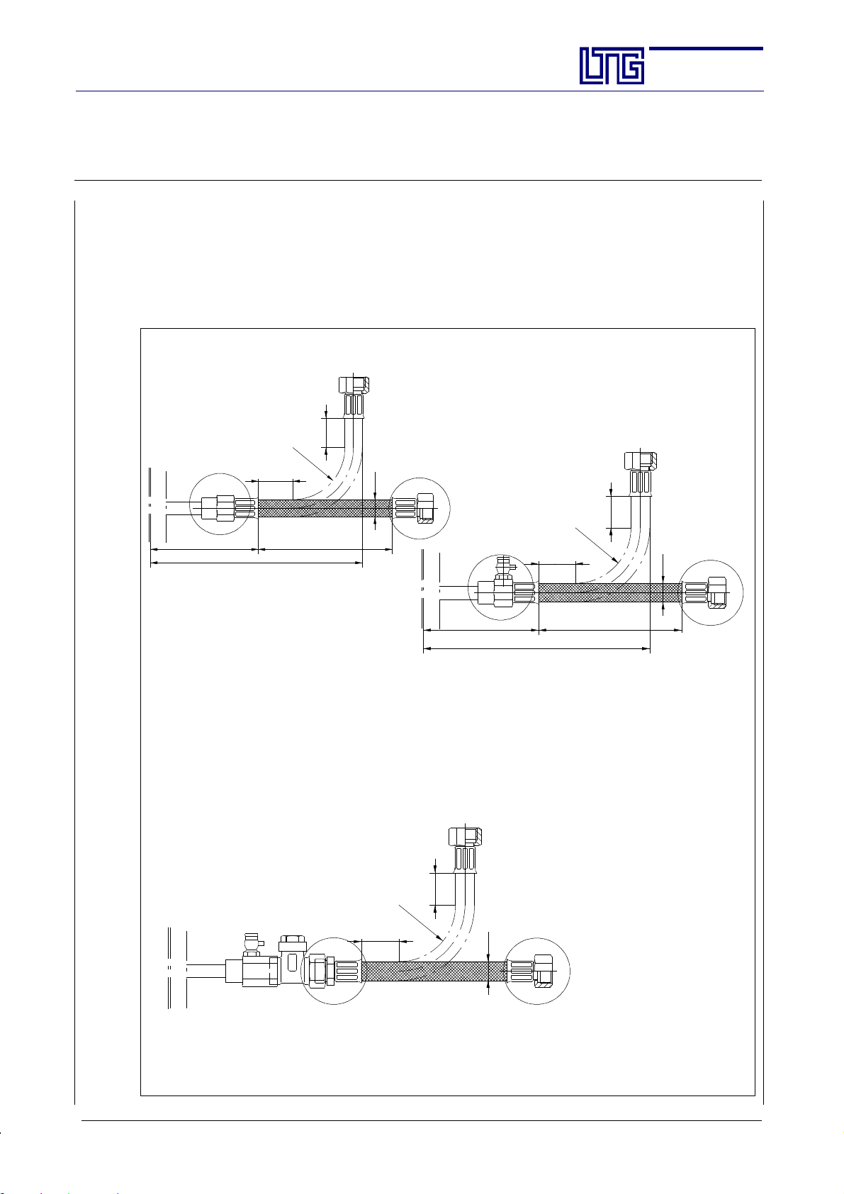
Example for water connection using flexible hose
(Quick coupling connection to heat exchangers)
min.R50
ca.100
min.35
ca.200
min.35
Ø17 DN 12
min.150
Section:
Page:
Date:
min.R50
min.35
AG--B 201.1e
35
Feb. 2010
min.35
Ø17 DN 12
ca.100
ca.200
min.150
Hose without insulation. For insulated hoses, dimensions will change accordingly
(10 mm Armaflex insulation).
Hose for connection to heat exchanger with smooth tube end diameter 12 mm,
connection types: quick coupling, quick coupling with venting
Different hose connections, thread diameter acc. to customer requirements or standard 1/2”
Example for water connection
using transition - LTG description VSG 10/ 2 EH (venting) -,
straight-way valve and flexible hose
min.R50
min.35
min.35
Ø15 DN 10
Hose without insulation. For insulated hoses, dimensions will change accordingly.
Hose for connection to angle or straight-way valve,
connection type: AGK, external thread, tapered 1/2”
Different hose connections, thread diameter acc. to customer requirements or standard 1/2”
E LTG Aktiengesellschaft ⋅ Grenzstraße 7 ⋅ D-70435 Stuttgart ⋅ +49 (0711) 8201-0 ⋅ Fax -720
Internet: http://www.LTG-AG.de ⋅ E-Mail: [email protected] ⋅ Printed in Germany ⋅ Ausgaben mit früherem
Datum werden hiermit ungültig ⋅ Technische Änderungen vorbehalten ⋅ Former editions are invalid ⋅ Subject to technical modifications.
Page 36
The Innovation Company
LTG Aktiengesellschaft
Instructions for Installation, Use and Maintenance
Fan Coil Unit Type VFC
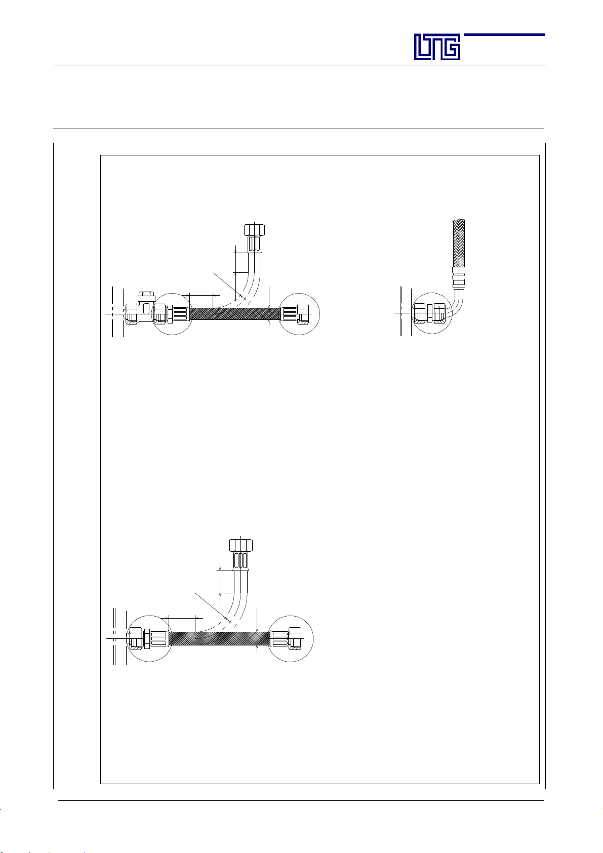
Example for water connection using valve and flexible hose
_
variant)
min. R 50
min.150
min. 35
Ø17 DN 12
(straight and 90
Hose without insulation. For insulated hoses, dimensions will change accordingly.
(10 mm Armaflex insulation
Hose for connection to angle or straight-way valve,
Connection type AGK, external thread, tapered 1/2”
Different hose connections, thread diameter acc. to customer requirements or standard 1/2”
Connection for direct screwing into the heat exc hanger in case of angle connection,
Connection type: double nipple 1/2”--1/2”; UFD hose connection, 1/2” flat seal union nut
Section:
Page:
Date:
AG--B 201.1e
36
Feb. 2010
Example for water connection for direct screwing into the heat exchanger
min. R 50
min.150
min. 35
Ø17 DN 12
Hose without insulation. For insulated hoses, dimensions will change accordingly.
Connection for direct screwing into the heat exchanger
Connection type: AGK, external thread, tapered 1/2”
Different hose connections, thread diameter acc. to customer requirements or standard 1/2”
E LTG Aktiengesellschaft ⋅ Grenzstraße 7 ⋅ D-70435 Stuttgart ⋅ +49 (0711) 8201-0 ⋅ Fax -720
Internet: http://www.LTG-AG.de ⋅ E-Mail: [email protected] ⋅ Printed in Germany ⋅ Ausgaben mit früherem
Datum werden hiermit ungültig ⋅ Technische Änderungen vorbehalten ⋅ Former editions are invalid ⋅ Subject to technical modifications.
Page 37
The Innovation Company
LTG Aktiengesellschaft
Instructions for Installation, Use and Maintenance
Fan Coil Unit Type VFC
Section:
Page:
Date:
AG--B 201.1e
37
Feb. 2010
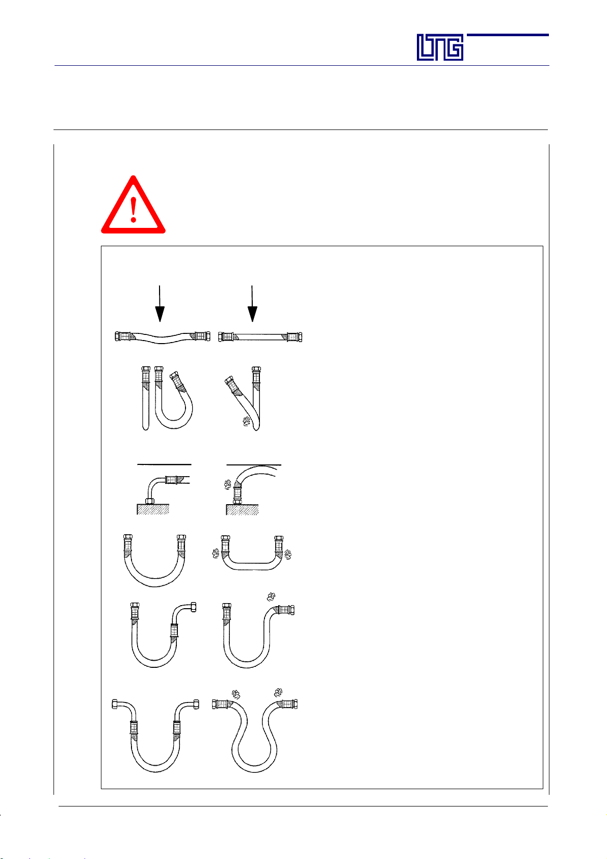
4.2.1 Instructions for Installation of Water Connections Using Flexible Hoses
Warranty will only apply if the following instructions are observed and if installation is performed in compliance with DIN--EN regulations.
In particular, corrosive, electrochemical, and bacteriological charges are to
be excluded taking appropriate preventive measures.
correct incorrect
- Pressure and exposition to heat may result in slight
elongation of the hose.
Therefore, newly placed hoses must consider such
potential elongation.
- Do not fall below the admissible bending radius
(chart), neither during transport, nor during
R
min
installation or when installed.
If it should turn out impossible to keep the admissible bending radius, choose a different installation
type.
- For minimum length see chart below.
If the hose is being placed by bending it, check
whether there is sufficient hose le ngth to allow for
an open bow in order to avoid kinking and destruction of the hose at the connecting points.
- Absolutely avoid distorting or kinking the flexible
connection.
- Do not subject the hose to any tensile or pressure
loads applied from outside, neither during installation nor operation.
- Do not retighten rigid connections (outer threa d)
after fixing the second connection since this might
result in distortion of or damage to the hose.
- In general, tightness of the connect ion (hose/connector) is the responsibility of the technician performing the installation.
- Any sealing materi al included in the delivery is t o
be verified by the technician for its suitability since
the hose manufacturer has no information about the
material or geometry of the connections.
E LTG Aktiengesellschaft ⋅ Grenzstraße 7 ⋅ D-70435 Stuttgart ⋅ +49 (0711) 8201-0 ⋅ Fax -720
Internet: http://www.LTG-AG.de ⋅ E-Mail: [email protected] ⋅ Printed in Germany ⋅ Ausgaben mit früherem
Datum werden hiermit ungültig ⋅ Technische Änderungen vorbehalten ⋅ Former editions are invalid ⋅ Subject to technical modifications.
Page 38
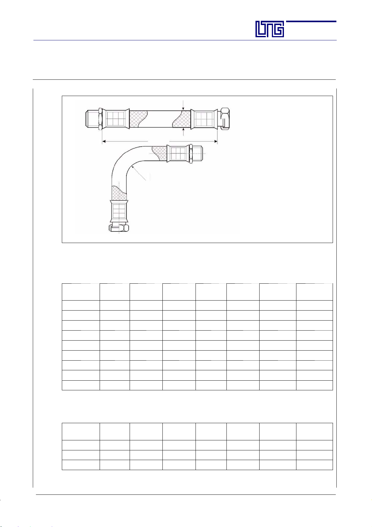
The Innovation Company
LTG Aktiengesellschaft
Instructions for Installation, Use and Maintenance
Fan Coil Unit Type VFC
D
ext.
L
min
R
min
Section:
Page:
Date:
AG--B 201.1e
38
Feb. 2010
Armoured hose Oxystop up to +70 _C (diffusion inhibiting, marked through weaved--in blue strip)
Armoured hose EPDM up to +93 _C (vapour permeable, not marked)
ND
hose
D
A
PN
[bar]
R
min
L
min
L
min
=90_
L
min
= 180_
L
min
= 360_
06/08 12 15 27 60 140 180 260
10 14 15 40 60 190 250 260
12 18 15 60 80 260 360 550
15 22 12 70 95 300 420 640
19 27 10 80 100 350 480 730
25 34 10 100 125 430 590 900
32 44 10 160 140 650 900 1400
40 54 6 180 160 750 1030 1600
50 64 6 230 210 940 1300 2020
Armoured hose Oxyblock
*at+30
_C / 10 bar at + 50 _C (vapour impermeable, marked through weaved--in blue--white strip)
ND
hose
D
A
PN
[bar]
R
min
L
min
L
min
=90_
L
min
= 180_
L
min
= 360_
08 13,5 16 * 110 100 310 490 830
10 16 16 * 130 100 380 580 990
12 17 16 * 150 100 450 680 1150
E LTG Aktiengesellschaft ⋅ Grenzstraße 7 ⋅ D-70435 Stuttgart ⋅ +49 (0711) 8201-0 ⋅ Fax -720
Internet: http://www.LTG-AG.de ⋅ E-Mail: [email protected] ⋅ Printed in Germany ⋅ Ausgaben mit früherem
Datum werden hiermit ungültig ⋅ Technische Änderungen vorbehalten ⋅ Former editions are invalid ⋅ Subject to technical modifications.
Page 39
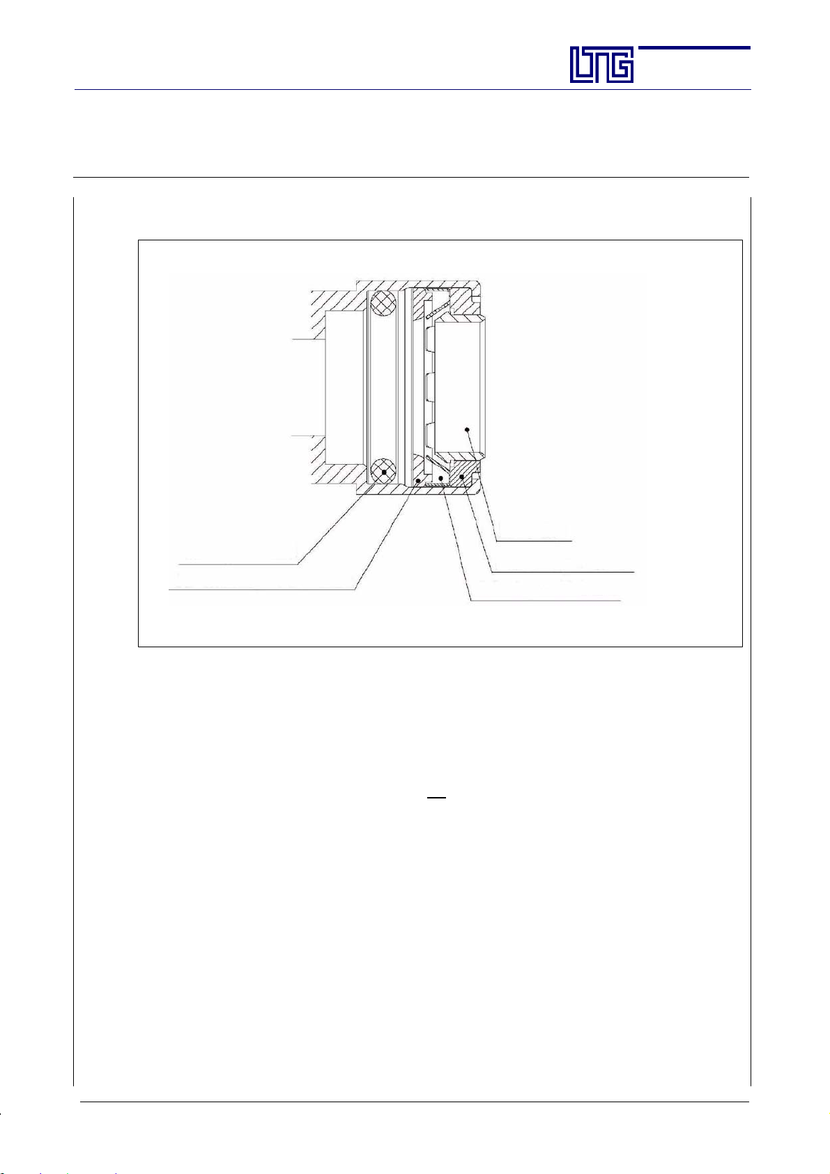
The Innovation Company
LTG Aktiengesellschaft
Instructions for Installation, Use and Maintenance
Fan Coil Unit Type VFC
4.4.2 Plug-in Connection Cuprofit
Section:
Page:
Date:
Inner ring
AG--B 201.1e
39
Feb. 2010
O--Ring EPDM
Polysulfone ring
Outer ring of coppe r
Stainless steel retaining ring
Tube connection of plug--in fitting and bright copper tube according to EN 1057 and RAL 641/1 or suitable
brass or red brass socket.
This permanently tight connection is suitable for concealed installation.
Using special tools, this connection may be detached up to three times when not under pressure.
Prior to reconnection, check for undamaged condition of the seal.
Check every installation for tightness when completed.
Due to their specific de sign, Cuprofit connectors are not
suitable for use as groundingconduct ors for electrical
installations and therefore not to be considered in the compensation of potential.
Maximum operating pressure 10 bar / 93 _C. Test pressure 16 bar / 30 _C.
E LTG Aktiengesellschaft ⋅ Grenzstraße 7 ⋅ D-70435 Stuttgart ⋅ +49 (0711) 8201-0 ⋅ Fax -720
Internet: http://www.LTG-AG.de ⋅ E-Mail: [email protected] ⋅ Printed in Germany ⋅ Ausgaben mit früherem
Datum werden hiermit ungültig ⋅ Technische Änderungen vorbehalten ⋅ Former editions are invalid ⋅ Subject to technical modifications.
Page 40
The Innovation Company
LTG Aktiengesellschaft
Instructions for Installation, Use and Maintenance
Fan Coil Unit Type VFC
4.3 Condensate Connection
Remove the condensate drainage plugs before connecting
the condensate lines!
Condensate formation occurs when the cold water supply temperature is belowthe ambient air dew pointtemperature. Neither LTG Induction Units nor LTG Fan Coil Units have been designed for an operation with
steady condensateformation which is why specialcare must betaken whensetting thewater inlet temperature
not to fall below the dew point temperature. If necessary, provide a continuous control of the wate r temperature based on outside air humidity.
On request, units are available in a special insulat ed version for condensing operation (please consider when
designing and ordering). In any case, please observe the following:
Air conditioning with centralized cooling and dehumidification (water temperature > 13 _C)
A certain water supply temperature will result in condensate formation since the temperature is below the
ambient air dewpoint. This dewpoint, however,depends onindoor air humidity.The water supplytemperature may be 1-- 2 K be low the dew point of the air since the air temperature on the pipes is higher than the
actual water temperature.
If rooms are ventilated with a maximum supply air humidity of e.g. 8.5 g/kg L
ture may be lowered to 15_C without risk of condensate formation.
In case of an increased humidity of the air, there a two solutions:
Case A: Condensate tray not connected (condensate socket closed by plug)
- If outside air humidity is high keep windows closed.
- Alternative: If windows are opened use a window contact with closing/time--delayed opening
system.
- Alternative: A central system controls the water supply temperature based on the outside air
humidity whenever windows are opened, i.e. in case of a high humidity of the air the water supply temperature is increased. This will, however, reduce the cooling capacity.
Case B: Condensate tray connected
- No need for a window contact or central cold water supply temperature raise in case of high
outside air humidity.
- If a short--term increase of t he indoor air humidity is probable (unit in the intermediate ceiling
above a wet room, e.g. a hotel) it is recommended to provide the t ray with a thermal insulation.
- In general, VPI 6022 requirements are to be met with the installation of any condensate drain
connection on site.
Ventilation without dehumidification or window opening (water temperature > 16 _C)
In case of a ventilation without dehumidification the water supply temperature must be 16 _C or up.
If the supply air is not dehumidified or the ventilation is realized by opening windows, the air humidity
might be very high which is why the following case will have to be considered:
The condensate tray must
- A central c old water control and weather related cold water supply temperat ure raise is recommended
since opening the windows might result in outside air with a high humidity entering the room and the
temperature dropping below the air’s dew point.
Whatever the case of application, all water carrying pipes and fittings outside
the condensate tray’s range must be insulated.
If a condensate drainage system is connected there must be sufficient slope
and proper drainage of the condensate produced. Condensate trays and the
condensate drainage system require cleaning and sanitation checks on a regular basis.
be connected.
Section:
Page:
Date:
AG--B 201.1e
40
Feb. 2010
the water supply tempera-
tr
E LTG Aktiengesellschaft ⋅ Grenzstraße 7 ⋅ D-70435 Stuttgart ⋅ +49 (0711) 8201-0 ⋅ Fax -720
Internet: http://www.LTG-AG.de ⋅ E-Mail: [email protected] ⋅ Printed in Germany ⋅ Ausgaben mit früherem
Datum werden hiermit ungültig ⋅ Technische Änderungen vorbehalten ⋅ Former editions are invalid ⋅ Subject to technical modifications.
Page 41
The Innovation Company
LTG Aktiengesellschaft
Instructions for Installation, Use and Maintenance
Fan Coil Unit Type VFC
4.4 Check after Installation
Verify for the unit’s proper connection to a residual current device (RCD).
Mechanical Check
Having com pleted the installation the unit is to be checked for any mechanical damages. Remainders of the
packaging materia l and dust in or on the unit must be removed.
Check the following:
- leakproofness of the water connections (including heat exchanger connections),
- the insulati on of all cold water carrying components to the heat exchanger for dam age,
- the condensate drai nage (optional) for c lear passage and sufficient slope,
- the fixing screws for proper fit,
- the suspension for rigidity and sufficient load--bearing capacity (ceiling units),
- the unit for not contacting the facade and the raw floor except via the seals provided and the supporting
feet (floor units),
- the line volta ge and frequency to match t he data given on the type plate,
- the electrical connections for proper execution and conformity to pertinent regulations,
- proper functioning of the control (optional) ,
- proper functioning of the motors (fan, actuators) without friction noises,
- the unit’s fixation,
- the diffusion area/diffusion grille of the unit to be free of any obstructions,
- proper horizontal alignment, accurate to dimension,
- sufficient water hose lengths and strainless laying,
Section:
Page:
Date:
AG--B 201.1e
41
Feb. 2010
Check for Media Supply
- Check for proper availability of primary air, cold water, warm water, and electrical power or compressed
air for the control.
- Check whether voltage and line frequency comply with the data given on the actuator’s type plate. Never
operate controldevices with inappropriate voltage or frequency since this mightresult in destruction of the
units and put people at risk.
Control T echnical Equipment
Supply of control devices by LTG Aktiengesellscha f t is optional, however it is the rule for actuators for units
with dampers. Control valves are often factory--mounted.
Check for Proper Functioning
Turn the temperature control’s selection knob slowlyfrom one end position to the other while keeping an eye
on the control dampers and linkage or the valves. Dampers and valves must move correspondingly quite
smoothly and without rattling noises from one end position to t he other. No exceptional noise must be produced by the electric actuators. In case the units show damages have them properly repaired by an expert. Damper linkageshave been gauge adjustedin the factory and, therefore, require LTG Aktiengesellschaft’s skilled
personnel for readjustment.
Starting Standard Operation
Then set the temperature controller tothe desired temperature. After a certaintime the indoor air temperature
should meet the setpoint.
E LTG Aktiengesellschaft ⋅ Grenzstraße 7 ⋅ D-70435 Stuttgart ⋅ +49 (0711) 8201-0 ⋅ Fax -720
Internet: http://www.LTG-AG.de ⋅ E-Mail: [email protected] ⋅ Printed in Germany ⋅ Ausgaben mit früherem
Datum werden hiermit ungültig ⋅ Technische Änderungen vorbehalten ⋅ Former editions are invalid ⋅ Subject to technical modifications.
Page 42
The Innovation Company
LTG Aktiengesellschaft
Instructions for Installation, Use and Maintenance
Fan Coil Unit Type VFC
5. First Use
Prior to first use any installation work and all checks must have been completed.
Check for proper water and power supply.
Please take special care to ensure that the starting voltage is adequate.
Having started the unit an a ir flow should be perceivable from the outlet grille. Only very minor air diffusion
and motor sounds should be audible. Other sounds such as frictionor impact mightindicate damages resulting
from transport or installation.
Section:
Page:
Date:
AG--B 201.1e
42
Feb. 2010
E LTG Aktiengesellschaft ⋅ Grenzstraße 7 ⋅ D-70435 Stuttgart ⋅ +49 (0711) 8201-0 ⋅ Fax -720
Internet: http://www.LTG-AG.de ⋅ E-Mail: [email protected] ⋅ Printed in Germany ⋅ Ausgaben mit früherem
Datum werden hiermit ungültig ⋅ Technische Änderungen vorbehalten ⋅ Former editions are invalid ⋅ Subject to technical modifications.
Page 43
The Innovation Company
LTG Aktiengesellschaft
Instructions for Installation, Use and Maintenance
Fan Coil Unit Type VFC
Section:
Page:
Date:
6. Operation, Maintenance and Repair
All units are virtually maintenance free , however certain things should be observed.
Any maintenance and repair work must be performed by skilled and trained
staff only.
Before starting any maintenance or repair work the unit is to be completely
disconnected from the main power supply!
6.1 Heat Exchanger, Water Connections and Condensate Tray
It is recommended to vacuum clean the heat exchanger and the dry condensate tray on a regular basis.
The heat exchanger blades are sharp--edged. Wear gloves for protection!
Check water connections and heat exchanger for tightness and possible corrosion damages.
If corrosion occurs inside the heat exchangers skilled staff must check the water treatment.
In case of condensation and existing condensate drainage the condensate tra y will have to be wet cleaned and
checked for contamination on a regular basis as required by VDI 6022.
6.2 Filter
Unit with filter
If a recirculated air filter exists it requires replacement about 2--3 months after first use of the unit. By that
time, it will probably be saturated from carpet lints and construction dust residues.
Exact timing is subject to local conditions.
The filter must be replaced on a regular basis, every 6 months to 2 years depending on dust formation.
A 6--month filter change interval will be required if the unit is operated in an environment with heavy dust
load, a lot of foot traffic, and only minimum primary air filter quality.
A 2--year filter change interval might be appropriate if the unit is operated under c onditions without foot traf-
fic, in a clean environment, and with a very good primary air filter quality.
Unit without filter
The exchanger(s) is/are to be vacuum cleaned about 2 to 3 months after their putting into operation. By that
time, heat exchangers are usually visibly polluted from carpet lints and construction dust remainders. Exact
timing is subject to local conditions.
Heat exchanges will then have to be vacuum cleaned on a regular basis, every 6 months to 2 years depending
on dust formation. This gains particular importance considering that condensate formation might result in
hard--to--remove dust caking.
A 6--month cleaning interval might be required if the unit is operated in an environment with heavy dust load,
a lot of foot traffic, and onlyminimum primary air filter quality, incase of condensate formation on the cooler
even sooner.
A 2--year cleaning interval might be appropriate if the unit is operated under conditions without foot traffic,
in a clean environment, with a very good primary air filter quality and without condensate formation on the
cooler.
6.3 Fan
The fan is virtually maintenance--free. However, after an operating time of about 20,000 hours a failure of
the fan may occur.The fan must be checked for smooth and proper running, possible imbalance, and damages
to the bearing. The fan must also be checked on a regular basis, every 6 to 12 months, for potentia l dust and
foreign bodies on the impeller. Severe pollution and foreign bodies may result in premature wear of the bearing and fan.
AG--B 201.1e
43
Feb. 2010
E LTG Aktiengesellschaft ⋅ Grenzstraße 7 ⋅ D-70435 Stuttgart ⋅ +49 (0711) 8201-0 ⋅ Fax -720
Internet: http://www.LTG-AG.de ⋅ E-Mail: [email protected] ⋅ Printed in Germany ⋅ Ausgaben mit früherem
Datum werden hiermit ungültig ⋅ Technische Änderungen vorbehalten ⋅ Former editions are invalid ⋅ Subject to technical modifications.
Page 44
The Innovation Company
LTG Aktiengesellschaft
Instructions for Installation, Use and Maintenance
Fan Coil Unit Type VFC
6.4 Repair
If the damage is not obviously a mere ”damage to the bodywork”, e.g. on the condensate tray or outlet, units
should be completely replaced and checked by the factory (in case of defects to the fan it might be sufficient
to replace the fan unit without need to disconnect the system entirely from the water supply system).
First, the unit is to be completely disconnected from the power supply by an expert.
The filter in front of the heat exchanger is easy to replace since it is fixed to the unit with a simple adhesive
strip.
Replacement of the control unit should be performed by skilled staff only
or by the factory.
Replacement of individual components, e.g. a fan bearing, is not recommended since the greater number of settings can only be performed in the factory using special equipment.
Warranty applies to complete fans only.
Section:
Page:
Date:
AG--B 201.1e
44
Feb. 2010
E LTG Aktiengesellschaft ⋅ Grenzstraße 7 ⋅ D-70435 Stuttgart ⋅ +49 (0711) 8201-0 ⋅ Fax -720
Internet: http://www.LTG-AG.de ⋅ E-Mail: [email protected] ⋅ Printed in Germany ⋅ Ausgaben mit früherem
Datum werden hiermit ungültig ⋅ Technische Änderungen vorbehalten ⋅ Former editions are invalid ⋅ Subject to technical modifications.
Page 45
The Innovation Company
LTG Aktiengesellschaft
Instructions for Installation, Use and Maintenance
Fan Coil Unit Type VFC
6.5 Troubleshooting and Corrective Action
Tr ouble Source Action
Cold or hot water supply not
No heating or cooling by the
unit despite of fan running
No air movement at the unit’s
outlet grille
No control signal is applied to
the (valve) actuator, or it is not
the one according to setting
No valve spindle m ovement
when actuator motor signal is
being changed
Unit is heating or cooling, but
set temperature is not achieved
Despite highest fan speed only
weak air movement at the fan
diffuser
Measured cold water temperature is lower than the setting
(ask technician for setting).
Therefore, diffused air temperature is extremely low
operating.
Heat exchanger and water supply lines have room temperature
The unit’s fan is not operating
Deficient control
Actuator is stuck
Window is open Close window
Filter or heat exchanger polluted
Suction or diffuser opening
blocked or polluted
Cold water temperature to the
units is too low
Section:
Page:
Date:
AG--B 201.1e
45
Feb. 2010
Ensure cold or hot water supply
Check and remove trouble
Check fan coil unit shut-- off
valve
Put fan into operation. If necessary, force starting with highest
speed level
Check fan power supply. If necessary, replace fuses or switch
on main power supply
Replace drive unit.
Have unit checked by a specia-
lized technician replacing or repairing broken parts
Try to release the stuck actuator
by setting the temperature controller from ”max. hot” to
”max. cold” and vice versa.
If unsuccessful, remove actuator, clean or replace
Replace filter
Clean heat exchanger
Remove objects in front of the
diffuser and protective grille.
Observe a minimum distance of
10 cm in front of the casing.
Clear of objects
Check cold water control including valve and actuator. If necessary, restore proper settings,
replace or repair broken parts
E LTG Aktiengesellschaft ⋅ Grenzstraße 7 ⋅ D-70435 Stuttgart ⋅ +49 (0711) 8201-0 ⋅ Fax -720
Internet: http://www.LTG-AG.de ⋅ E-Mail: [email protected] ⋅ Printed in Germany ⋅ Ausgaben mit früherem
Datum werden hiermit ungültig ⋅ Technische Änderungen vorbehalten ⋅ Former editions are invalid ⋅ Subject to technical modifications.
Page 46
The Innovation Company
LTG Aktiengesellschaft
Instructions for Installation, Use and Maintenance
Fan Coil Unit Type VFC
Tr ouble Source Action
Part of the condensate trays is
overflowing despite of drainage
system
Unit drips
Increased indoor air humidity
perceivable
Water inlet/return temperature
difference too low
Audible impact noises
Audible grinding noises
Audible knocking noises
Condensate drainage system
clogged
Leaking or overflowing condensate tray
Considerable moisture sources
in the room
Water volume possibly too high Check water volume balancing
Fan not running or not conveying sufficient air
Inlet temperature too high in
the cooling mode
Fan bearing damage
Foreign bodies in the fan
Fan imbalanced resulting in
contact to the casing
Suspension improperly fixed
Casing vibrations
Section:
Page:
Date:
AG--B 201.1e
46
Feb. 2010
Remove clogging
In the meantime, increase inlet
temperature or shut off unit
Replace leaking condensate
tray
Check condensate pump
Check drainage system
Remove moisture sources
If impossible, temporarily shut
off unit water--side
Check fan and terminals
Maybe speed is too low
Heat exchanger and filter polluted
Check temperature and cooling
circuit
Replace bearing or drive
(only by
LTG A ktiengesellschaft)
Remove foreign body from impeller (only with the unit off)
Replace drive and impeller unit
Check and fix suspension
E LTG Aktiengesellschaft ⋅ Grenzstraße 7 ⋅ D-70435 Stuttgart ⋅ +49 (0711) 8201-0 ⋅ Fax -720
Internet: http://www.LTG-AG.de ⋅ E-Mail: [email protected] ⋅ Printed in Germany ⋅ Ausgaben mit früherem
Datum werden hiermit ungültig ⋅ Technische Änderungen vorbehalten ⋅ Former editions are invalid ⋅ Subject to technical modifications.
Page 47
The Innovation Company
LTG Aktiengesellschaft
Instructions for Installation, Use and Maintenance
Fan Coil Unit Type VFC
6.6 Maintenance Intervals of the Individual Components
Component Activity
Unit, in general
Filter
Heat exchanger
Dirt and
condensate tray
Fan
Check for pollution, damage, corrosion,
correct positioning and fixation
Check for pollution, damage and odours 3
Check the filter layer for tightness 3
Replace filter medium (document) 12* x
Check for hygienic condition 3
Check for pollution, damage and corrosion 6
Clean to maintain function 6 x
Check water connections 12
Check proper function of entry and return 12
Ven t x
Check for hygienic condition 6
Check for pollution, damage, leak tightness
and corrosion
Clean to maintain function x
Check for hygienic condition 3
Check heat insulation for damage (visual check) x
Check drain and siphon for proper functioning x
Check for pollution, damage, corrosion and proper
fixation
Clean to maintain function x
Check impeller for imbalance 12
Check bearing for noises 12
Check vibration damper for proper functioning 12
Check safety device for proper functioning 12
Clean chambers from the inside x
Check for hygienic condition 6
Section:
Page:
Date:
AG--B 201.1e
47
Feb. 2010
To perform
months as required
12
3
6
*Shorten replacement intervals if outside or recirculating air are extremely dust loaded.
VDI 6022 sanitation requirements must be observe d.
E LTG Aktiengesellschaft ⋅ Grenzstraße 7 ⋅ D-70435 Stuttgart ⋅ +49 (0711) 8201-0 ⋅ Fax -720
Internet: http://www.LTG-AG.de ⋅ E-Mail: [email protected] ⋅ Printed in Germany ⋅ Ausgaben mit früherem
Datum werden hiermit ungültig ⋅ Technische Änderungen vorbehalten ⋅ Former editions are invalid ⋅ Subject to technical modifications.
Page 48
The Innovation Company
LTG Aktiengesellschaft
Instructions for Installation, Use and Maintenance
Fan Coil Unit Type VFC
7. Spare Parts
The following spare partsare availableand may beordered fromLTG Aktiengesellschaft stating unit type
and description.
Quan-
tity
Ident No. Description
1 4--pipe heat exchanger size 500 for VFC 1
1 4--pipe heat exchanger size 630 for VFC 1
1 4--pipe heat exchanger size 800 for VFC 1
1 4--pipe heat exchanger size 1000 for VFC 1
1 4--pipe heat exchanger size 1250 for VFC 1
1 2--pipe heat exchanger size 500 for VFC 1
1 2--pipe heat exchanger size 630 for VFC 1
1 2--pipe heat exchanger size 800 for VFC 1
1 2--pipe heat exchanger size 1000 for VFC 1
1 2--pipe heat exchanger size 1250 for VFC 1
1 530065 Draintraysize630forVFC 10
1 530073 Draintraysize800forVFC 10
1 531170 Drain tray size 1000 for VFC 10
1 1003369 Drain tray size 1250 for VFC 10
1 1008313 Terminal box electrical connection 1
1 Fan size 500 with 5-speed motor 1
1 Fan size 630 with 5-speed motor 1
1 Fan size 800 with 5-speed motor 1
1 Fan size 1000 with 5-speed motor 1
1 Fan size 1250 with 5-speed motor 1
1 Capacitor 1 uF 5
1 Capacitor 1.5 uF 5
Filter mats in rolls of 40 m 1 roll
Adhesive Velcro tape 100 m
Section:
Page:
Date:
AG--B 201.1e
48
Feb. 2010
Minimum
order quantity
For heat exchangers please state connection (1/2”, smooth copper tube)
8. Decommissioning, disposal
When the fan is taken out of service, is no longer used and isdisposed of as waste, the following must be complied with:
- all steel parts are waste for recycling
- all plastic parts are waste for recycling
- all secondary substances and lubricants must be disposed of in accordance with the provisions of the EWC
(European Waste Catalogue) classification.
E LTG Aktiengesellschaft ⋅ Grenzstraße 7 ⋅ D-70435 Stuttgart ⋅ +49 (0711) 8201-0 ⋅ Fax -720
Internet: http://www.LTG-AG.de ⋅ E-Mail: [email protected] ⋅ Printed in Germany ⋅ Ausgaben mit früherem
Datum werden hiermit ungültig ⋅ Technische Änderungen vorbehalten ⋅ Former editions are invalid ⋅ Subject to technical modifications.
 Loading...