

Page 1
LT-DMX-1809 DMX-SPI Signal Decoder LT-DMX-1809 DMX-SPI Signal Decoder
LT-DMX-1809
DMX-SPI Signal Decoder
warranty
5 years
LT-DMX-1809 converts the universal standard DMX512 signal into SPI(TTL) digital signal to drive LEDs
compatible driving IC, it could control every channel of the LED lights, realize 0~100% dimming or editing
all sorts of changing effect.
DMX-SPI decoder are widely used in LED flashing word string light, LED dot light, SMD strip, LED digital
tubes, LED wall light, LED pixel screen, Hi-power spotlight, flood light, etc.
1. Product Parameter:
LT-DMX-1809
Input Signal:
Input Voltage:
Output Signal:
Decoding Channels:
DMX512 Socket:
Compatible with WS2811/WS2812/WS2812B, UCS1903/UCS1909/UCS1912/UCS2903/UCS2909/UCS2912 TM1803/
TM1804/TM1809/1812/ driving IC.GS8206(BGR)/SM16703
Note: grey level from best or worst depend on the IC types, it is nothing with the LT-DMX-1809 decoder performance.
DMX512
5~24Vdc
SPI
512 Channels/Unit
3-pin XLR, Green Terminal
Dimming Range: 0~100%
Working Temperature: -30℃~65℃
Dimensions: L125×W64×H40(mm)
Package Size: L135×W70×H50(mm)
Weight (G.W.): 300g
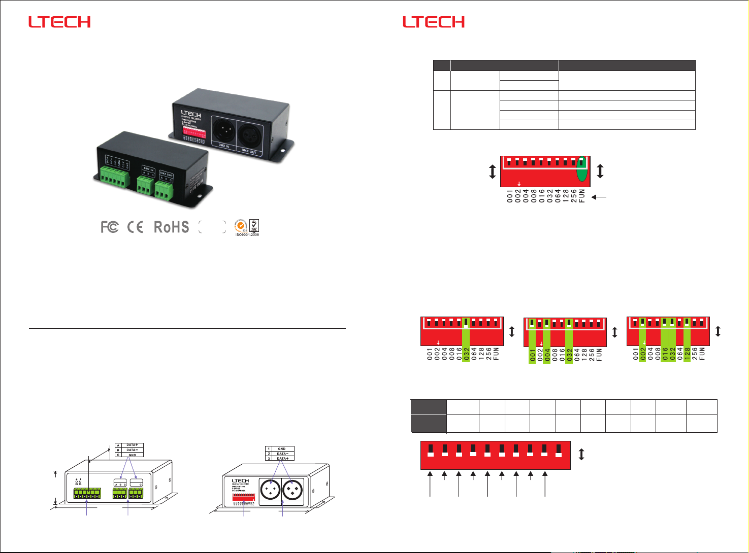
2. Configuration Diagram:
64mm
A
DMX IN DMX OUT
DAT
CLK
GND
DC+
40mm
125mm
Power Input / Signal output
Terminal
A B
Green Block
(DMX Terminal)
1 2 3 4 5 6 7 8 9 10
Address
Dip Switch
1 2
3
ONDIP
DMX IN DMX OUT
115mm
3-pin XLR
(DMX Terminal)
12
3
1
with
3. Output Port Definition:
Input Port
Port
DC+
DC-
DC+
DATA
CLK
GND
5-24V LED power supply inputdc
LED power supply output anode
Data cable
Clock cable (N/A)
Ground (DC-)cable
No.
Power Supply
1
Output Port
2
Connect LED
Dip Switch Operation:
4.
0
1
2
3
4
5
6
7
8
9
10
ON
1
4
4.1 How to set DMX address via dip switch:
FUN=OFF (the 10th ) Modedip switch=OFF DMX
The Decoder enter into DMX control mode automatically when receiving DMX signal.
Like figure upward: FUN=OFF is high speed(upward), FUN=ON is low speed (downward)
1. The driving chip of this decoder has option for high and low speed(800K/400K), please choose the
suitable speed according to the design of your LED lights, in most cases, it is high speed.
2. DMX address value = the total value of (1-9), to get the place value when in “on” position, otherwise
will be 0.
E.g.1: Set Initial Address To 32. E.g.2: Set Initial Address To 37.
OFF
1
2
3
4
5
6
7
8
9
ON
10
4.2 Self-testing Mode:
When no DMX signal, Self-testing Mode
Static
Black
1=on
Static
Red
Dip Switch
Self-test
Function
1-9=off
1
2
3
4
ON
5
ON
001+004+03 2=37
4=on 7=on
3=on 6=on
Static
Static
Blue
Static
Yellow
Green
6
7
8
OFF
4
3
2
1
Static
Static
Green
Static
Red
Yellow
Static
Static
Blue
[Attn] When several dip switches are ON, subjected to the highest switch value.
As the figure above shows, the effect will be 7 colors smooth at 7 speed level.
Purple
7
8
7 Colors
Jumping
7 Colors
9
Smooth
10
ON
6
5
Static
Cyan
Static
White
2
Function
OFF
ON
Valu e
E.g.3: Set Initial Address To 178.
OFF
1
2
3
4
5
6
9
10
ON
ON
002+016+03 2+128 =178
5=on
Static
Static
Cyan
Static
White
Purple
For changing effects (Dip Switch 8 9=ON): /
DIP switch 1-7 is used to realize 7 speed
levels. (7=ON, the fastest level)
7
8=on 9=on2=on
7 Colors
Jumping
www. ltech -led.com
8
9
10
7 Colors
Smooth
OFF
ON
Page 2
LT-DMX-1809 DMX-SPI Signal Decoder LT-DMX-1809 DMX-SPI Signal Decoder
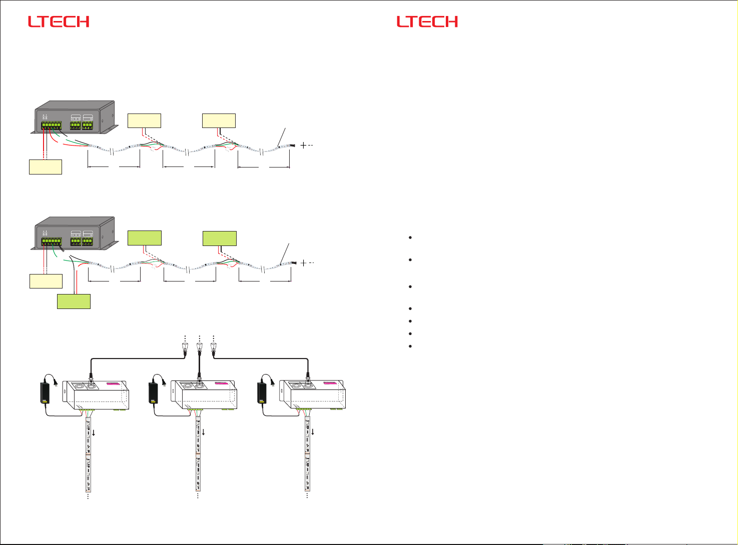
5. Wiring Diagram:
5.1 LED pixel strip wiring diagram.
A. Conventional connection method.
A
T
DMX IN DMX OUT
DA
CLK
GND
DC+
dc
12V
Power supply
A B
GND
DA
+
R
G
G
B. Special connection method - light fixtures and controller using different operating voltages.
A
DMX IN DMX OUT
DAT
CLK
GND
DC+
5-24V
dc
Power supply
GND
DA
+
GND
36V
dc
Power supply
A B
R
G
G
+
5.2 DMX wiring diagram.
12V
dc 12V
Power supply
GND
+
R
G
G
5M
36V
dc
Power supply
GND GND
+ +
R
G
G
5M
Power supply
R
R
G
G
G
G
5M
Power supply
R
R
G
G
G
G
5M
DMX Signal Input
dc
GND
+
R
Pixel Strip
R
G
G
G
G
5M
36V
dc
R
Pixel Strip
R
G
G
G
G
5M
6. Attention:
6.1 The product shall be installed and serviced by the qualified person.
6.2 This product is non-waterproof. Please avoid the sun and rain. When installed outdoors please ensure it is
mounted in a water proof enclosure.
6.3 Good heat dissipation will prolong the working life of the controller. Please ensure good ventilation.
6.4 Please check if the output voltage of the LED power supply used comply with the working voltage of the
product.
6.5 Please ensure that adequate sized cable is used from the controller to the LED lights to carry the
current. Please also ensure that the cable is secured tightly in the connector.
6.6 Ensure all wire connections and polarities are correct before applying power to avoid any damages to the
LED lights.
6.7 If a fault occurs, please return the product to your supplier. Do not attempt to fix this product by yourself.
7. Warranty Agreement:
7.1 We provide lifelong technical assistance with this product:
A 5-year warranty is given from the date of purchase. The warranty is for free repair or replacement if
cover manufacturing faults only.
For faults beyond the 5-year warranty, we reserve the right to charge for time and parts.
7.2 Warranty exclusions below:
Any man-made damages caused from improper operation, or connecting to excess voltage and
overloading.
The product appears to have excessive physical damage.
Damage due to natural disasters and force majeure.
Warranty label, fragile label and unique barcode label have been damaged.
The product has been replaced by a brand new product.
ower Supply
P
Adaptor
AC Adapter
Model no.
Input : 100-240V-1.5A
Output : DC12V---5A
Warning: INDOOR USE ONLY
An amplifier is needed when more than 32 decoders are connected, signal amplification should not be more
*
DMX IN
DMX OUT
10
9
8
7
LT-DMX-1809
A
T
DC+
DA
CLK
GND
IN
+VC
GND
12Vdc
RI
750
SPI(TTL)
B
R
511
Signal Output
R
471
G
471
471
R
511
471
RS
104
682
R
511
471
471
OUT
GND
IN
+VC
GND
RI
750
Pixel Strip Pixel Strip Pixel Strip
B
R
511
R
471
G
471
471
R
511
471
RS
104
682
R
511
471
471
OUT
GND
ower Supply
P
Adaptor
ON
6
5
4
3
2
1
AC Adapter
Model no.
Input : 100-240V-1.5A
Output : DC12V---5A
Warning: INDOOR USE ONLY
12Vdc
DMX IN
DMX OUT
LT-DMX-1809
A
DC+
DAT
CLK
GND
IN
+VC
GND
RI
750
SPI(TTL)
B
R
511
Signal Output
R
471
G
471
471
R
511
471
RS
104
682
R
511
471
471
OUT
GND
IN
+VC
GND
RI
750
B
R
511
R
471
G
471
471
R
511
471
RS
104
682
R
511
471
471
OUT
GND
10
9
8
7
ower Supply
P
Adaptor
ON
6
5
4
3
2
1
AC Adapter
Model no.
Input : 100-240V-1.5A
Output : DC12V---5A
Warning: INDOOR USE ONLY
12Vdc
DMX IN
DMX OUT
LT-DMX-1809
TA
DC+
DA
CLK
GND
IN
+VC
GND
RI
750
SPI(TTL)
B
R
511
Signal Output
R
471
G
471
471
R
511
471
RS
104
682
R
511
471
471
OUT
GND
IN
+VC
GND
RI
750
B
R
511
R
471
G
471
471
R
511
471
RS
104
682
R
511
471
471
OUT
GND
10
9
8
than 5 times continuously.
3
7.3 Repair or replacement as provided under this warranty is the exclusive remedy to the customer. We
ON
7
6
5
4
3
2
1
shall not be liable for any incidental or consequential damages for breach of any stipulation in this
warranty.
7.4 Any amendment or adjustment to this warranty must be approved in writing by our company only.
★This manual only applies to this model. We reserve the right to make changes without prior notice.
www. ltech -led.com
4
Update Time: 2020.05.22_A3
 Loading...