

Page 1
LT-890
DMX512 CV Decoder
1
2
209mm
12345678910
ONDIP
RUN
FUN=OFF
(
DMX)
FUN=ON
(
TEST)
222mm
42mm
108mm
DMX
I
N
DMX
O
UT
DC-
DC+
DC-
DC+
CH04CH01 CH07 CH10CH05CH02 CH08 CH11CH06CH03 CH09 CH12V+V+ V+ V+
CH07-CH12
CH07-CH12
CH01-CH06
CH01-CH06
LT-890 DMX512 CV Decoder Manual LT-890 DMX512 CV Decoder Manual
LTECH LTECH
ZHUHAI LTECH ELECTRONIC TECHNOLOGY CO., LTD.
WWW.LTECHONLINE.COM
Tel: +86 756 620 8823 Fax: +86 756 620 8833
warranty
5 years
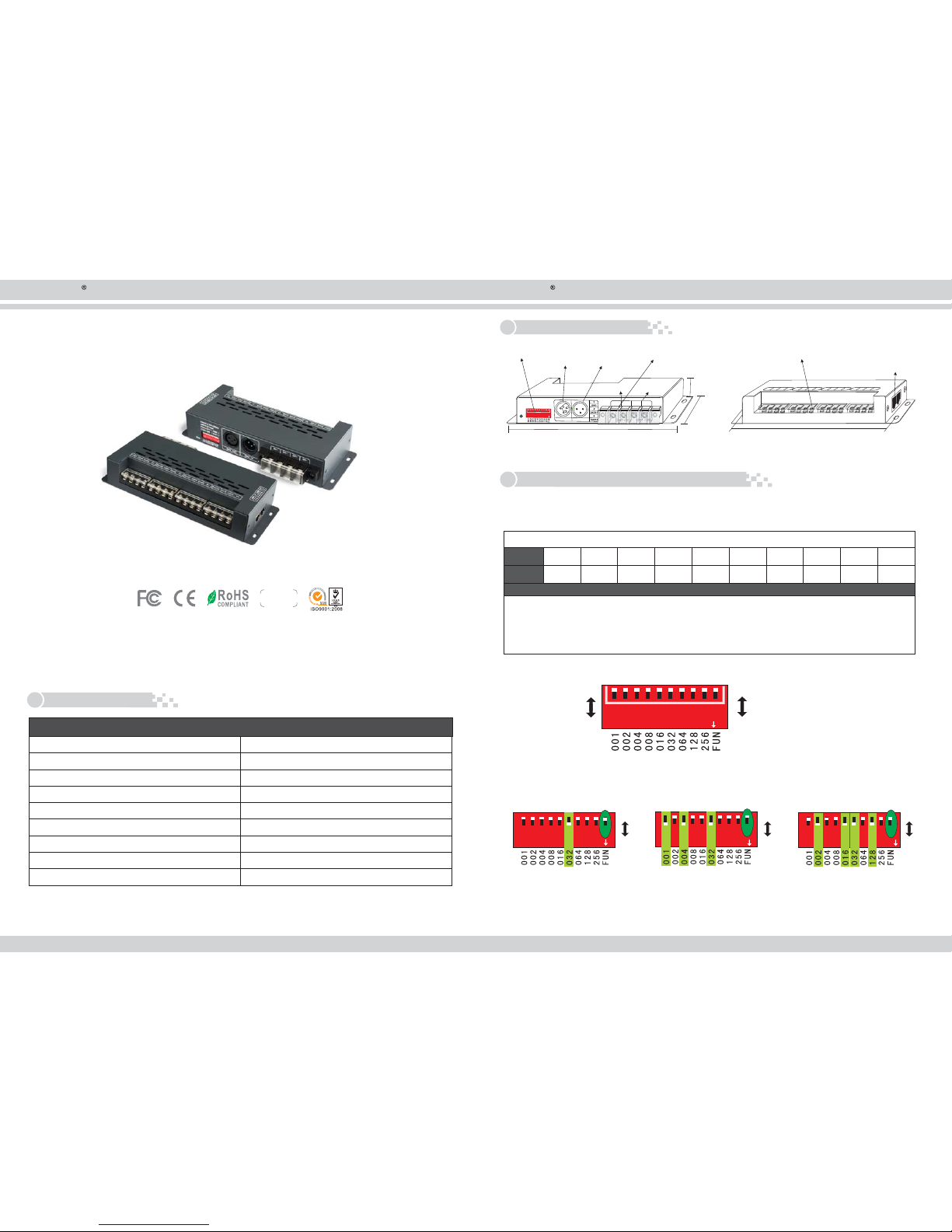
LT-898 DMX CV Decoder converts the universal standard DMX512 signal into PWM signal to drive
LEDs. this compact decoder work with DMX512 Console, with 256 levels gray scale output per
channel. Realize 0-100% brightness and various changing effect. equiped with DMX standard XRL-3,
RJ45 interface, easy to operate. And it can control single color, two color, RGB LED light.
1. Product Parameter:
LT-890
Input Voltage
Max Load Current
Max Output Power
Working Temperature
Package Size
Weight(G.W.)
DC5V 24~DC V
5A×12CH Max 60A
300W/720W/1440W(5V/12V/24V)
L222×W108×H42mm
L230×W112×H44mm
Dimension
-30 ~65℃℃
650g
DMX512
Input Signal
XLR-3, RJ45
DMX512 Socket
DMX Input Output
RJ45
/
LED Lights Connection Terminals
DC5V-DC24V
Power Input
DMX Input
XLR-3
DMX Output
XLR-3
DIP Switch
3. How to Set DMX Address via Dip Switch:
1) Set DMX512 Original Address:
Accept DMX512 signal only when the DIP switch FUN=OFF, as Figure 1
1
2
3
5
6
78
10
4
001 002 004 008 016
032
064 128 256
DMX512 initial address code is equal to the total amount of the DIP switches’ number
from 1 to 9, press DIP switch downward(ON: at position :”1”), user can get the number of
its position, if pressing upward(at position”0”), the number of its position is 0.
Specification
DIP
Address
FUN
9
When Dip switch 1 9 are OFF, the-.initial DMX address defaults to 1
FUN=OFF (DMX )Mode
FUN=ON (Self-test Mode )
Example1: Set Initial Address To 32 Example2: Set Initial Address To 37 Example3: Set Initial Address To 178
*
001+004+032=37
002+016+032+128=178
22445577889
9
OFF OFF OFF
ON ON ON
11336
6
ON
ON ON
2 45 78913 6
10
10
10
12345678910
ON
0
1
OFF
ON
2. Configuration Diagram:
Side A Side B
Page 2
3
1
1
1
1
1
1
1
1
2
2
2
2
2
2
2
2
3
3
3
3
3
3
3
3
4
4
4
4
4
4
4
4
5
5
5
5
5
5
5
5
6
6
6
6
6
6
6
6
7
7
7
7
7
7
7
7
8
8
8
8
8
8
8
8
9
9
9
9
9
9
9
9
10
10
10
10
10
10
10
10
ON
ON
ON
ON
ON
ON
ON
ON
0
1
0
1
0
1
0
1
0
1
0
1
0
1
0
1
OFF
ON
OFF
ON
OFF
ON
OFF
ON
OFF
ON
OFF
ON
OFF
ON
OFF
ON
4
CH04CH01 CH07 CH10CH05CH02 CH08 CH11CH06CH03 CH09 CH12V+V+ V+ V+
DC+
DC-DC+DC-
LT-890
CH04CH01 CH07 CH10CH05CH02 CH08 CH11CH06CH03 CH09 CH12V+V+ V+ V+
DC+
DC-DC+DC-
LT-890
CH04CH01 CH07 CH10CH05CH02 CH08 CH11CH06CH03 CH09 CH12V+V+ V+ V+
DC+
DC-DC+DC-
LT-890
DC+
DC-DC+DC-
LT-890
CH04CH01 CH07 CH10CH05CH02 CH08 CH11CH06CH03 CH09 CH12V+V+ V+ V+
DC+
DC-DC+DC-
LT-890
CH04CH01 CH07 CH10CH05CH02 CH08 CH11CH06CH03 CH09 CH12V+V+ V+ V+
DC+
DC-DC+DC-
LT-890
CH04CH01 CH07 CH10CH05CH02 CH08 CH11CH06CH03 CH09 CH12V+V+ V+ V+
13% Brightness
25% Brightness
38% Brightness
50% Brightness
63% Brightness
75% Brightness
88% Brightness
100% Brightness
DMX OUT
DMX OUT
DMX OUT
DMX IN
DMX IN
DMX IN
USB-DMX
Signal converter
DMX512
PC Console
DMX IN
DMX IN
DMX OUT
DMX OUT
DC5V-24V
DC5V-24V
DC+
DC-DC+DC-
LT-8 90
CH04CH01 CH07 CH10CH05CH02 CH08 CH11CH06CH03 CH09 CH12V+V+ V+ V+
DC+
DC-DC+DC-
LT-890
CH04CH01 CH07 CH10CH05CH02 CH08 CH11CH06CH03 CH09 CH12V+V+ V+ V+
RGB LED Strip
Single Color Strip
R
-
-
-
-
-
-
-
-
-
-
-
-
R
R
R
G
G
G
G
B
B
B
B
+
+
+
+
+
+
+
+
G
R
B
G
R
B
G
R
B
G
R
B
G
R
B
G
R
B
G
R
B
G
R
B
G
R
B
G
R
B
G
R
B
G
R
B
G
R
B
G
R
B
G
R
B
G
R
B
G
R
B
G
R
B
G
R
B
G
R
B
G
R
B
G
R
B
G
R
B
G
R
B
G
R
B
G
R
B
G
R
B
G
R
B
G
R
B
G
R
B
G
R
B
G
R
B
G
R
B
G
R
B
G
R
B
G
R
B
G
R
B
G
R
B
G
R
B
G
R
B
G
R
B
G
R
B
G
R
B
G
R
B
G
R
B
G
R
B
G
R
B
G
R
B
G
R
B
G
R
B
G
R
B
G
R
B
LT-890 DMX512 CV Decoder Manual LT-890 DMX512 CV Decoder Manual
LTECH LTECH
ZHUHAI LTECH ELECTRONIC TECHNOLOGY CO., LTD.
WWW.LTECHONLINE.COM
Tel: +86 756 620 8823 Fax: +86 756 620 8833
2) Testing Function:
4. Connection Diagram:
1) Connecting RGB LED Lights:
2) Connecting Single Color LED Lights:
RJ45 Socket
XLR-3 Socket
3) DMX Console Connection
Output
Output
Output
Input
Input
CH07-CH12
CH07-CH12
CH01-CH06
CH01-CH06
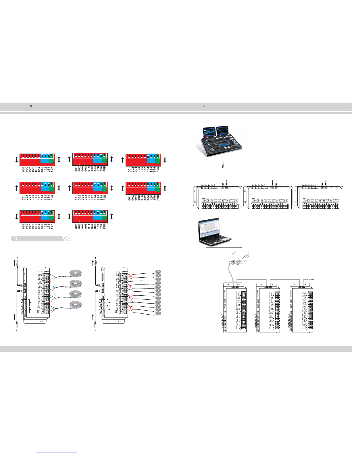
Regarding the dip switch, Turn on 10th for testing mode. No.1-6 control 12 Channels accordingly.
Namely one switch control 2 continuous channels. No.7-9 is for brightness setting, 8 levels,
which applies for all channels.
Page 3
5
6
LT-890 DMX512 CV Decoder Manual LT-890 DMX512 CV Decoder Manual
LTECH LTECH
ZHUHAI LTECH ELECTRONIC TECHNOLOGY CO., LTD.
WWW.LTECHONLINE.COM
Tel: +86 756 620 8823 Fax: +86 756 620 8833
5. Attention:
6. Warranty Agreement:
1) The product shall be installed and serviced by a qualified person.
2) This product is non-waterproof. Please avoid the sun and rain. When installed outdoors please
ensure it is mounted in a water proof enclosure.
3) Good heat dissipation will prolong the working life of the controller. Please ensure good ventilation.
4) Please check if the output voltage of any LED power supplies used comply with the working voltage of
the product.
5) Please ensure that adequate sized cable is used from the controller to the LED lights to carry the current.
Please also ensure that the cable is secured tightly in the connector.
6) Ensure all wire connections and polarities are correct before applying power to avoid any damages to
the LED lights.
7) If a fault occurs please return the product to your supplier. Do not attempt to fix this product by yourself.
1) We provide lifelong technical assistance with this product:
A 5-year warranty is given from the date of purchase. The warranty is for free repair or replacement
and covers manufacturing faults only.
For faults beyond the 5-year warranty we reserve the right to charge for time and parts.
2) Warranty exclusions below:
Any man-made damages caused fro m improp er operation, or connecting to excess voltage and
overloading.
The product appears to have excessive physical damage.
Damage due to natural disasters and force majeure.
Warranty label, fragile label and unique barcode label have been damaged.
The product has been replaced by a brand new product.
3) Repair or replacement as provided under this warranty is the exclusive remedy to the customer.
LTECH shall not be liable for any incidental or consequential damages for breach of any stipulation
in this warranty.
4) Any amendment or adjustment to this warranty must be approved in writing by LTECH only.
★ This manual only applies to this model. LTECH reserves the right to make changes without prior notice.
Update Time 2014.05.25:
 Loading...