


LS TRACTOR
OPERATOR'S MANUAL
LS TRACTOR
OPERATOR'S MANUAL
PO Box 70, Battleboro, NC 27809
Tel : 252-984-0700
Fax : 252-984-0701
www.lstractor.com
www.lstractorusa.com
OHSAS 18001
MT1-SERIES
P/NO
52121611/01
DATE
20170000
MT122 MT125


Contents
2. Instruction for Safe Operation
(1)Thenameofeachpart····································2-1
2-1. Boarding and Exiting the tractor
(1)Boardingthetractor··································2-2
(2)Driver’sseatswitch······································2-2
(3)Seatadjustment·········································2-3
(4)Seatbelt··············································2-4
(5)Exitingthetractor········································2-4
2-2. Safety device
(1) Hood (Bonnet) · · · · · · · · · · · · · · · · · · · · · · · · · · · · · · · · · · · · ······2-5
(2) Fender · · · · · · · · · · · · · · · · · · · · · · · · · · · · · · · · · · · · · · · · · · · · · · · 2-5
(3)PTOsafetycoverandprotectioncap·························2-5
(4)Roll-OverProtectiveStructure(ROPS)························2-6
1. General Notices for Safety
1-1. Before using the tractor ··································1-1
1-2. Safety Precautions (Read this for safety before using)
(1)Noticesbeforeusingthetractor·····························1-4
(2)NoticeswhenstartingEngine ······························1-7
(3)Noticeswhileoperating/usingthetractor·······················1-8
(4) Notices when connecting Implement · · · · · · ···················1-10
(5)Noticeswhentowingthetractor····························1-11
(6)Noticeswhentransportingthetractor························1-11
(7)Noticeswhenservicingthetractorafterwork ···················1-12
(8) Notices when handling Diesel Fuel ··························1-13
(9)Noticeswhenleavingthetractor····························1-14
(10)NoticesrelatingtoToxicsubstances························1-14
1-3. Long-term storage
(1) Preparation for storage ··································1-15
(2) Check & Maintenance during storage ························1-16
(3)PreparationforReuse···································1-16
1-4. Notices for “Use & Disposal” related to the environment ·········1-17
1-5. Symbols ·············································1-18
1-6. Safety Decals
(1) Handling and Maintenance of Safety Decals ····················1-19
(2)SafetyDecalsandattachingposition·························1-19

Contents
3. Instruments and Controls
3-1. Instrument panel and Front controls
(1) Instrument panel ········································3-2
(2)Keyswitch············································3-4
(3)Turnsignallightswitch····································3-4
(4)Lightswitch············································3-5
(5)Hazardwarninglightswitch································3-5
(6)PTOswitch ········································3-6
(7) Brake pedal ······································
···3-7
(8)Parkingbrakelever····································
· ·3-7
(9)Throttlelever··········································3-8
(10) HST forward / reverse pedal (HST type) · · · · · · · · · · · · · · · · · · · · · · 3-8
(11)Cruisecontrolswitch(HSTtype)····························3-9
3-2. Left / Right-hand side Levers and Pedals
(1) Range gear shift lever····································3-11
(2)4WDlever····································3-11
(3)Worklightswitch···································3-12
(4)PTOselectlever·······································3-12
(5)Electricalpoweroutletsocket······························3-13
(6) Differential lock pedal· · · · ·································3-13
3-3. Hydraulic System
(1)Safetyprecautions···································
· ··3-14
(2)Steeringsystem·····································
· · · 3-15
(3)HydraulicliftControl··································
· · · 3-16
(4)Midmowerheightadjustmentknob·························3-17
(5)RemotecontrolleverandQuickcoupler(optional)···············3-18
(6)Joysticklever(iffitted)··································3-19
(7)HydraulicSystemDiagram ································3-20
4. Operation and Work
4-1. Engine start and stop
(1)Enginestart············································4-1
(2)Startincoldweather·····································4-3
(3)Enginestop············································4-3
4-2. How to drive and stop
(1)Howtodrive ·········································· 4-4
(2) Changing speed ········································4-6
(3)EmergencyStop········································4-7

Contents
4-3. How to handle new tractor
(1)Checkpoints··········································4-11
(2) Notices in handling new Tractor ·····························4-11
4-4. Attaching Implement
(1)3-pointlinkage·········································4-12
(2)Powertake-off(PTO)shaft································4-16
(3)HitchandDrawbar(optional)·······························4-19
(4) 7-Pole connector (optional)································4-20
(5)Technicallymaximumpermissiblemass······················4-21
(6) Tires and Load capacity · · · · · ·····························4-22
(7) Adjusting Wheel tracks and tire replacement · · · · · · · · · · · · · · · · · · · 4-22
(8) Using Front-end loader (optional) · · · · · · · · · · · · · · · · · · · · · · · · · · · 4-23
(9)AdjustingSteeringangle·································4-25
(10) Recommended maximum specification of implements ···········4-26
4-5. Driving Speed········································4-27
5. Lubrication and Maintenance
5-1. Access for Maintenance ··································5-1
5-2. Maintenance Chart ······································5-2
5-3. Lubricants and Capacity ·································5-4
5-4. First 50 hour check ·····································5-5
5-5. Check before Starting (Daily check)
(1)Engineoil·············································5-6
(2)Fueltank··············································5-7
(3) Instrument panel & Indicators ·······························5-7
(4)Turnsignallights,LightsandHorn···························5-8
(5)Enginecoolant·········································5-9
(6) Air cleaner (Dry type)····································5-9
(7)CleaningofRadiatorandRadiatorscreen······················5-10
(8)Tireairpressureanddamage······························5-10
(9)TighteningstateofBoltsandNutsofeachpart ·················5-11
(10) Adjustment of Brake pedal play · · · · · · · · · · · · · ···············5-12
(11)AdjustmentHSTcontrollinkage(HSTtype)····················5-13
(4)Stoppingtractor·········································4-8
(5)Drivingtractorontheroad ·································4-9
(6)Parking ············································ 4-10

Contents
5-6. First 50 hour check
(1)Lubricatinggrease······································5-14
(2)CleaningofRadiatorandRadiatorscreen·····················5-14
(3)CheckingTransmissionoil································5-14
(4)CheckingFrontaxleoil ··································5-15
(5)Batterycheck·········································5-15
(6) Air cleaner (Dry type)····································5-15
(7) Hydraulic hoses and Leakage · · · · · · · · · · · · · · · · · · · · · · · · · · · · · · 5-15
5-7. Every 250 hour check
(1)ReplacingEngineoilandFilter·····························5-16
(2)ReplacingHydraulicoilfilter·······························5-17
(3)TensionadjustmentofFanbelt·····························5-18
(4)Drainfueltank····································5-18
(5)Toe-in···············································5-19
5-8. Every 500 hour check
(1) Changing Front axle oil · · · · · ·····························5-20
(2) Changing Transmission oil · · ······························5-20
(3)ReplacingFuelfiltercartridge······························5-21
(4) Replacing Air cleaner element (Dry type)······················5-22
5-9. Every 1000 hour check
(1)AdjustingEngineValveclearance···························5-23
5-10. Every 1500 hour check
(1)Inspectandcleanfuelinjectionnozzle,ifnecessary ·············5-23
(2)Inspectcrankcasebreathersystem··························5-23
5-11. Every 2000 hour or 2-year check
(1)ReplacementofEnginecoolant·····························5-24
(2)Checkandreplacefuelhosesandcoolanthoses················5-25
5-12. General maintenance (When required)
(1)Air-bleedingfromFuelsystem ·····························5-26
(2)Fuse&Mainfuse·······································5-27
(3) Battery handling and Notices ······························5-29
5-13. Troubleshooting ·····
·································5-33
6. Dimension and Specification ·······················6-1

1 -1
1. General Notices for Safety
1-1. Before using the tractor
※ Must read and understand this operator’s manual carefully and
always refer to information and prescriptions outlined in this
manual to prevent all potential health and safety risks.
◆ General information for intended use
z Your tractor is designed and manufactured to pull, to carry, to supply the power a variety of mounted
or towed equipment for agriculture. Do not use the product for other purposes than intended by the
manufacturer and outlined in this manual. Do not use this tractor for light/heavy forestry applications.
z Do not use the product beyond its limits of terrain gradient and stability than outlined in this manual.
Using the tractor beyond these limits may cause a overturning accident.
z Do not use the tractor on higher speeds than allowed by the load of the tractor and road condition.
Always choose a suitable driving speed to maintain the stability of the tractor.
z Do not use the tractor near or on soft verges of canals and brooks or banks and verges that are
undermined by rodents. The tractor may sink sideways and roll-over.
z Do not use the tractor on brittle bridge heads and poor bridge floors. These constructions may
collapse and cause overturning of the tractor. Always check out the condition and carrying
capacity of bridges and ramps prior to engage.
z Do not use the tractor without wearing the seat belt and Roll-Over Protective Structure (ROPS)
during operations where roll-over or tip-over hazards exist. The ROPS will only be fully effective when
the driver remains attached to his/her seat.
z Do not use equipment mounted on the tractor which is not correctly matching and firmly fixed.
Such equipment may increase the risk for roll-over and hit the tractor when coming loose.
z Do not use the tractor in combination with equipment arbitrary, without having consulted the
specific operator’s manual provided with the equipment. This manual alone cannot provide you
with all the information about safety operation of the combination.
z Do not use the tractor beyond its limits of dynamic stability. High speed, abrupt maneuvers, and
fast and short cornering will increase the risk of roll-over.
z Do not use the tractor for overloaded pulling work, in cases where you don’t know if the load will
yield, for instance when pulling stumps. The tractor may flip over when the stump is not yielding.
z Be extremely cautious when working with the tractor on forage silos without lateral con crete walls.
A wide track setting may improve the lateral stability of the tractor.
z Be cautious that the center of gravity of the tractor may increase when the front-end loader is
loaded or the three-point linkage are raised. In these conditions, the tractor may roll-over earlier than
expected.
z Do not step down from the tractor without shutting down the PTO, shifting the transmission
to neutral and applying the parking brak e.
zNever remove or modify or change the driver’s protection device or safety device arbitrary.

1 -2
◆ Safety Mark Description
- In the places where the cautions in usage are required, the marks such as “DANGER”, “WARNING”,
“CAUTION” are found.
- You should comply with the description marked on the decals attached on the product or the conten ts
marked with safety mark in this Operator's Manual.
Warning - This indicates a potential dangerous situation that may cause a serious
injury or death if not avoided.
Caution - This indicates a potential dangerous situation that may cause a light
injury or damage to the properties if not avoide d .
Notice - This indicates the instructions for right use for the safety of persons or
products.
Danger - This indicates a fatal dangerous situation that may cause a serious injury
or death if not avoided.
Notice
Caution
Warning
Danger
z You must take the necessary precautions to always be aware of the possible presence of
bystanders, certainly when maneuvering in confined areas. Keep people away from the tractor during
work. Pay the necessary attention while operating next to public roads or footpaths. Thrown objects
can get projected outside the field and hit unprotected people like bikers or pedestrians. Wait until it is
clear of bystanders.
z Do not violate the local traffic rules related to public roads and highways.
z Do not allow riders on the tractor; do not allow people standing on the access way or step to the
cab when the tractor is moving. Your view to the left will be obstructed and a rider risks to fall from the
tractor during unforeseen or abrupt movements.
z This tractor has only one operator station and is a one man operated vehicle. Other people on or
around the tractor during normal operation are not allowed.
z Always stay clear from implements operating area and especially do not stand between tractor
and trailed vehicle either three-point linkage when operating lift controls; ensure no bystanders
are near these operating areas.
z This tractor may be equipped with a number of sensors to control safety functio ns. Do not attempt
to bypass any function on the tractor. You will be exposed to serious hazards, and moreover, the
behavior of the tractor may become unpredictable.
z The manufacturer will not be responsible for the damage or safety problems caused by maintenance
or repair with non-genuine parts. It must be requested to use the genuine parts.
z When cleaning the tractor by using high pressurized water, do not inject water directly to the
electronic parts, wiring, air intake pipe, hot engine or muffler inside the bonnet.
z Maintenance and repair of the tractor is performed by skilled technical experts with the proper
tools authorized by the manufacturer.
z For damage or accidents caused by misuse or operation in violation of these rules, the manufacturer
and its distributors will not have any responsibility and warranty.
z Keep this operator’s manual for future reference at hand (on the tractor).

1 -3
Front
Rear
RightLeft
Fig.1-1
Fig.1-2
Fig.1-3
Engine No.
◆ Terminology
When reading this Operator's Manual, refer to
the right figure for the discrimination of the front/
rear/ left/ right direction.
Chassis No.
Running hour
TM number
Fig.1-4
◆ Product Identification
Your tractor has a exclusive chassis number and
engine number marked with product serial number
tag to identify the product. (See Fig.1-1)
In case of requesting service or parts from your
dealer, dealer will need chassis serial number,
engine serial number, TM number and running
hours displayed on the instrument panel. (See Fig.
1-3)
540/2933

1 -4
1-2. Safety Precautions - read this for safety before using.
(1) Notices before using the tractor
z For Safety operation : Before using this tractor,
read carefully and understand this operator's
manual and operator’s manual of the mounted
or trailed machinery on this tractor, and strictly
follow the instructions outlined in the operator’s
manuals.
Read Operator’s
Manual carefully.
▶Additional seat (where fitted) is used for driver training or instruction. Do not permit
anyone to ride on the tractor.
Warning
z Operator’s condition : The persons such as
patients, drunks, people on drugs, etc. are never
allowed to operate this tractor.
Only educated operators can use the tractor
after learning the usage of controls for moving,
stopping, turning and other operating.
z Suitable Clothes & Protect Entanglement :
When checking or operating the tractor, wear
tight fitting clothes and safety equipment instead
of loose or long clothes. Also, slippers, high
heel shoes are not suitable for operation. Wear
the low shoes or work shoes or boo ts.
Warning
▶Do not approach the rotating shaft such as PTO shaft or cooling fan, especia lly,
with loose clothing and long clothes. The entanglement in rotating shaft can cause
serious injury or death.
▶Stop the engine and be sure PTO shaft is stopped before getting near it.
z Keep Riders off : Riders on the tractor or implements obstruct the operator’s view and can be
thrown off the tractor. It can cause a serious injury or death. Riders should not be carried on the
tractor at any time.
z Safety Decal s : For right use and personal safety of the operator, the safety decals are attached to
the parts related with safety operation. Before using the tractor, comply with the safety instructions.
(For further information, refer to the section 1-6-(1)(2). “Safety Decals” in this manual.)
Especially, special cares must be taken for using the tractor in the places where the safety
signs such as Danger, Warning, Caution etc. are marked. (See page 1-2)

1 -5
z Protect Children : Pay special attention to children (or a child) while using the tractor or during
storage.
- Make sure children keep a safe distance from the tractor and all implements before using the
tractor. Be alert to the presence of children.
- Do not let children or an untrained person operate the tractor.
- Do not allow children to approach the tractor while the engine is running.
- When parking the tractor, remove the ignition key and lower implements to the ground for
children’s safety.
▶As children are very curious, they may do unexpected movements or actions.
Special care must be taken when operating tractor or equipment.
Warning
z Lamps : Do not modify the lamps or change the bulb capacity arbitrarily.
▶ Modified lamps or change bulb capacity may cause the traffic accident by
disturbing approaching driver’s views.
▶ If the lamp is blown out, replace it immediately with a genuine part. In case of
driving at night, it may cause a traffic accident.
Warning
z Periodical Check : “Lubrication and Maintenance” must be performed periodically. If necessary,
do it immediately and if not, it may cause a failure, reduction of product life or physical injury.
* Periodic Lubrication and Maintenance
Fuel, Oil, Filter, Air cleaner, Battery, Belt, Cable, Grease, Pedals such as clutch (if fitted) and
brake pedal(s), Tire air pressure, Wheel bolts, Toe-in, Electrical wirings, other items related to
safety.
z Genuine Parts : When replacing parts, you must use “Genuine Parts” of LS tractor. Contact your
authorized local dealer. If not, it may cause a failure, reduction of product life or serious injury.
z Restrict Maintenance : If repairing or changing some components or settings arbitrary, the
performance of the tractor can NOT be guaranteed, and may void the warranty. And also,
maintenance of the heavy weighted parts without special tools may cause serious injury. These
works have to be treated by well-educated and skilled service experts.
If required to check or repair the tractor due to such a trouble, or having any question about your
tractor, contact your authorized local dealer.
* The items that are not allowed to be modified or removed arbitrarily by user are as below :
- Protection structures such as PTO cover, Guar ds, Safety frame(Roll-ba r), Cab(if fitted), etc.
- Engine components, Fuel injection control and setting, etc.
- Automatic control equipment, Lamps, Transmission, Hydraulic valve and pressure setting s.
- Other parts that detail and where complicated adjustments are needed.

1 -6
z Protective Structures : For the operator’s safety, various protective structures, i.e. Bonnet (Hood),
Fan cover, PTO safety cover, PTO shaft protection cap, Roll-bar or another Roll-over Protective
Structure, etc are attached on the tractor. If these structures are modified or removed by user
arbitrarily, it may cause serious accident. Such behaviors are prohibited strictly.
▶ The Protective Structure and interconnecting components are a certified system.
Any damage, fire, corrosion or modification will weaken the structure and reduce
your protection. If this occurs, the Protective Structure MUST be replaced with a
new one. Contact your authorized local dealer for Protective Structure inspection
and replacement.
▶ In case of an accident, fire, tip or roll-over, the following MUST be performed by a
qualified technician before operating the tractor again.
- The Protective Structure MUST be replaced.
- The mounting or suspension for the Protective Structure , operator seat and
suspension, seat belt and mounting compo nen ts and wiring within the operat or’s
protective system MUST be carefully inspected for damage.
- All damaged parts MUST be replaced.
▶ DO NOT attach any device to the Protective Structure for pulling purposes.
▶ DO NOT weld, drill holes, attempt to straighten or repair the protective
structure. The modification can reduce the structural integrity of the
structure which can cause death or serious injury in the event of fire, tip, roll
over, collision or accident and void the warranty.
Warning
z Level of protection of the FOPS (Falling Objects Protective Structure) : This tractor does NOT
provide any protection against falling objects according to OECD code 10 stan da rd. It is
recommended to use a certified FOPS structure when working with front-end loaders.
z Level of protection against hazardous substances : This tractor does NOT provide any
protection against hazardous substances. Do not use the tractor with crop sprayers in hazardous
area.
z Level of protection of the OPS (Operators Protection Structure) : This tractor does NOT
provide any protection against
- low hanging wires and branches in the forest, orchard or construction area, etc.
- toppling trees, primarily in case a rear-mounted tree grab-crane is mounted at the rear of the
tractor.
- penetrating objects in the operator’s enclosure, primarily in case a winch is mounted at the rear of
the tractor.
- potential risks by using any optional equipment that might be available to deal with those hazards.
NEVER enter or operate these hazardous area without certified Operator Protective Structure
installed.

1 -7
(2) Notices when starting Engine
z Check each part with reference of “5. Lubrication
and Maintenance” in this manual. If necessary,
repair or replace it immediately. Especially,
check if safety protection structures or
covers are attached originally and the bolts
and nuts are tightened well.
z Before starting, check again if there are other
workers or children around the tractor and
implements and keep a safe distance.
z Start engine and opera te the tractor after sitting
on the driver’s seat with a securely fastened
seat belt.
z Place the shuttle lever, transmission gear lever
in NEUTRAL and especially check if parking
brake is applied.
z Lower the implements on the ground.
z Ensure that rear view mirrors and the other
mirrors (if fitted) are adjusted correctly, and
check the operation of the headlights and other
lights.
z For driver’s safety, to prevent an unintentional
start, movement and operation, several and
various start-safety interlock devices may be
equipped on your tractor. And, these installation
may need to do correct operation and follow the
procedure strictly. Read carefully section 4-1,
“Engine start and stop” in this manual before
trying to start engine.
z Do not short across the starter motor terminals
to start engine. It may cause a sudden start and
serious injury or death.
Warning
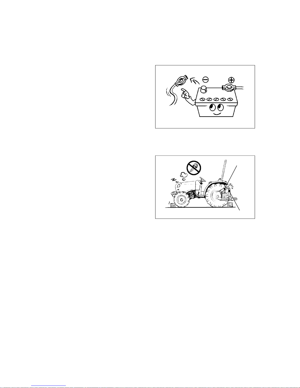
▶Do not start the engine in a closed area. The poisonous exhaust gas can cause
fatal damage to the driver or persons around.
Starter motor

1 -8
z Connect left and right brake pedal(s) while
driving on the road. (if fitted)
z DO NOT use differential lock device while
driving on the road or turning in the field.
z DO NOT ride your foot on the brake pedal(s) or
clutch pedal.
z Do not jump up/down while tractor is moving.
When getting on/off the tractor, use the grab rail
and sub step to prevent falls.
z Lower the driving speed enough before turning a
sharp curve. Especially, when you drive the
tractor with implements, make the turning radius
wider.
z DO NOT start or stop the tractor suddenly.
Engage the clutch and brake softly. If not, front
wheels can be lifted up and it is very dangerous.
z While working, clean regularly mud and debris
around the front/rear wheels and axles.
(3) Notices while operating/using the tractor
z Ventilation
Warning
▶It is very dangerous to work in
a closed area. The poison ou s
exhaust gas may cause serious
damage to the human body. If
you should work in this area,
make sure to ventilate well and
put on the protective mask.
z When driving the tractor in reverse, lower the
engine speed. Make sure to check if there is any
obstacle or person in the rear.
z DO NOT permit other people and especially
children approach within working area while
operating tractor and equipment.
z Noise and Vibration : When working between buildings or in confined spaces, the sound pressure
level can be increased. Wear suitable ear protectors in high noise level conditions. When working
with equipment in the field, vibration intensity from equipment may be increased. To reduce the harm
to the body, take a rest periodically.

1 -9
z To climb a steep slope, drive tractor slowly in
reverse up the slope rather than forward. It is
much safer.
z When turning tractor on a slope, the tractor can
be overturned easily. Pay attention to the
steering operation.
z When working at the edge of steep slope,
especially, when using heavy attached
implements, take special care about a turn-over.
z When working, wear the protectio n equipme nt
and tighten the seat belt.
z If the authorized passenger seat are not installed,
keep riders off.
z When crossing a high ridge, let down the
implement and go straight across the ridge at
low speed.
z When connectin g the implements to the
front/rear of the tractor, install the proper
additional weights in the rear/front of the tractor
to keep the balance of the tractor.
z On a downhill, operate the throttle pedal and
brake pedal slowly and DO NOT drive while the
transmission gear is in NEUTRAL.
z When working with a front/rear implement, be
careful not to touch the overhead power lines
and lightning strikes.
z Obey the traffic rules while driving on public
roads. Do not exceed the local legal speed limit.
Use a beacon or slow moving vehicle (SMV) to
indicate that the vehicle is slow moving.
z If you can not drive the tractor due to a failure,
move the tractor to a safe place and install
troubled vehicle (safety tripod).
(Day : backward 100m ( 328 ft )
Night : backward 200m ( 656 ft))
z Do not overuse the fuel, oil, etc and pay attention not to contact the skin directly. Generally, these
materials contain harmful materials to the human body. When you work in a area where hazardous
chemicals are sprayed, check the cabin filter (if fitted) and replace the filter with suitable one for the
purpose being used. To protect the body completely from these harmful materials, wear a safe
protection equipment such as mask, and clean the body after working.

1 -10
z Attach or detach the implement on wide and
level ground.
z Do not use the tractor in combination with
equipment arbitrary, without having consulted
the specific operator’s manual provided with the
equipment.
z You have to stay clear from the three-point
linkage when controlling it. Do not stay between
tractor and implement.
z Do not stay between tractor and trailed vehicle
for connecting/disconnecting or checking it.
Trailed vehicle may roll down or tractor can
move reverse.
z When towing the trailed vehicle, use only hitch
or drawbar. Do not tow by connecting with any
other structures.
z When connectin g heavy implements, apply the
parking brake and use the wheel chock.
z Do not attach over-weighted implement .
▶Before connecting or checking the implement, put PTO switch to “OFF” and place
PTO gear lever(if fitted) in neutral position.
▶When attaching or detaching the implement, make sure to fix the implement and
tighten the three point hitch pins correctly. If not, the serious troubles and injury can
occur during the operation.
▶If heavy loaded trailer is connected to 3-point linkage or any structure, it can cause
turnover or failure and serious injury. Make sure to use towing hitch or authorized
draw bar.
Warning
(4) Notices when connecting Implement
▶When connecting or disconnecting hydraulic coupler, lower implement on the
ground, turn off engine and check if the pressure of hydraulic line is released.
▶ When installing the implement having big hydraulic cylinders or lines, check oil
level in tractor transmission housing after installing the implements.
Caution

1 -11
z Check the horizontal and vertical permissible load of the hitch (or drawbar) before towing. The load
is different with trailer brake, and stopping distance increases with speed and weight of towed loads
and slope. Make sure you consider the total weight of the equipment and its load. (See section 4.
“Hitch and Drawbar” )
z Drive slowly when towing extremely heavy loads.
z Do not tow trailers that are not fitted with an independe nt braking system.
(5) Notices when towing the tractor
z If your tractor needs to be towed for a short
distance, use the hitch (or drawbar) or front
towing hook. Do not connect to other structures
such as rear axle, ROPS, front axle, steering
components for towing.
z Tractor can be steered for a short distance
without engine running, but it will be hard to turn
the steering wheel. If possible, run the engine for
steering and lubrication.
z When being towed, disengage the 4WD,
differential lock, parking brake and place all gear
shift levers in neutral position.
(6) Notices when transporting the tractor
z When transporting the tractor by truck, trailer,
etc, use suitable equipment or facilities to
load or unload the tractor.
z Fix the tractor tightly to the vehicle with heavy-
duty straps or chains.
z When fixing the rear of the tractor, use the hitch
or hitch support.
z When fixing the front of the tractor, use the
towing hook.
z When driving on public roads, the transpo rting
vehicle must have signs and lights required by
local regulation to avoid collision with a vehicle.
▶ When fixing the tractor, do not hook or connect chains to the 4WD shaft, steering
cylinder, tie-rod or front axle. These can be damaged by the chain or excessive
strain.
▶ In case of turbocharg er engin e (where fitted), cover the exhaus t outlet to protect
that the turbocharger does not rotate by air without lubrication.
Caution

1 -12
(7) Notices when servicing the tractor after work
z Check and maintenance must be performed after stopping the engine and cooling do wn the
engine sufficiently.
Warning
▶When opening radiator cap, hot
cooling water or steam may
explode. Remove the cap using
a thick rag or glove to prevent
serious burns.
z Keep an approved fire extinguis he rand First-aid-kit on your tractor.
z To prevent fire or explosion, keep flames or sparks away from battery. Do not grind, smoke, or weld
near a battery. For further information, see section 5-10-(3), “Battery handling and Notices” .
▶Always remove grounded (-) battery clamp first and assemble it last. If not, It
can cause an explosion by spark.
▶The gas generated from the battery is explosive. Keep cigarettes, sparks and
flames away from battery. Never check battery charge by placing a metal object
across the terminals.
▶Sulfuric acid in battery electrolyte is poisonous. It is strong enough to burn skin,
clothing and can cause blindness if splashed into eyes. Do not touch the battery or
liquid by bare hand without gloves or any protection. If electrolyte is splashed into
eyes, flush immediately with clean water for at least 20 minutes and get medical
attention.
▶Do not short circuit the battery posts with metal items.
▶Battery post, terminals and related accessories contain lead and lead compounds.
MUST WASH YOUR HANDS AFTER HANDLING.
Warning
z DO NOT pour water into the radiator or engine
when engine is hot. The engine or radiator may
crack.
Warning
▶Before removing hydraulic pipes or hoses and other parts, make sure to check that
hydraulic pressure is relieved completely. The leaks of pressurized oil can cause a
fatal physical injury.
▶Use proper protection equipments, befo re servicing hydrau lic system.
▶Before connecting or disconnecting the hydraulic quick coupler, lower the
implements to the ground, and check that hydraulic pressure is relieved.
z Before checking or repairing hydraulic system and fuel system, make sure the engine is stopped,
and all the transmission gears are in neutral, and lower the implements to the ground. The
leaks of pressurized fluid can cause a fatal physical injury. If injured by leaking fluid, get medical
attention immediately.
z Remove all mud and debris from the tractor after working. Especially check the engine area and
exhaust system.

1 -13
(8) Notices when handling Diesel Fuel
z Do not mix gasoline, alcohol or blended fuels to diesel fuel. These mixtures are explosive in fuel
tank.
z Never remove the fuel cap or refuel with the engine running or hot.
z Do not smoke while refueling the tractor. Keep any type of flame away.
z Maintain control of the fuel filler nozzle when filling the fuel tank.
z Do not fill the fuel tank to capacity. Fill only to the bottom of the filler neck to allow room for
expansion.
z Before servicing the tractor, attach a “DO NOT
OPERATE” warning tag to the tractor in an area
that will be visible.
See other side
Reason :
DO NOT
OPERATE
DO NOT
OPERATE
Signed by :
Tel :
z Keep the area used for serv i ci ng the tractor
clean and dry. Wet or oily floors are slippery. It
can be dangerous when working with electrical
equipment.
z Electric sensors, switche s, harness, involving
engine control unit(if fitted) is very sensitive and
delicate. Strictly prohibit injecting water,
mechanical impulse and any kind of welding
on engine.
z When lifting heavy parts like engine, axle, tire
etc., make sure to check the lifting facilities
have enough strength and capacity.
z Do not attempt to remove or unfasten the air conditioning components arbitrary. There is a
possible to be severely frostbitten or injured by escaping refrigerant. Contact your autho rized local
dealer to work air conditioning systems.
z Wipe up spilled fuel immediately and always
tighten the fuel tank cap securely.
z If the original fuel tank cap is lost, replace it with
an approved one.
z Never use fuel for cleaning purposes.
z Arrange fuel purchases so that summer grade
fuels are not held over and used in the winter.
z Before operating with Bio-Diesel, contact your
authorized local dealer for information relating to
the use and storage of Bio-Diesel.

1 -14
z Stop the tractor on level ground.
z Place the transmission gear in neutral and put
PTO switch to “OFF” position.
z Lower the mounted implemen ts on the ground .
z Apply the parking brake.
z Stop the engine and remove the ignition key.
z Before you leave the operator’s station , wait for
engine and all moving parts to stop.
z Have to apply the wheel chock when parking the
tractor on a slope unavoidably.
▶ When parking the tractor on a slope unavoidably while attaching the loaded
equipment, the tractor may move even if the parking brake is applied. Apply the
wheel chock and low speed transmission gear as follow. (if fitted)
-. Mechanical : downhill ⇒ Reverse 1gear / uphill ⇒ Forward 1gear
-. HST type : Lowest gear
Caution
(9) Notices when leaving the tractor
(10) Notices relating to T oxic substances
z Exhaust gas and some its constituents of the Diesel engine are known to the State of California to
cause cancer, birth defects, and other reproductive harm. (California proposition 65)
z Battery post, terminals and related accessories contain lead and lead compounds. MUST WASH
YOUR HANDS AFTER HANDLING.
1 -15
1-3. Long-term storage
(1) Preparation for storage
※ Wash the tractor cleanly and follow the
procedure as below.
z Apply grease or lubricant oil or spray paint to the
non-painted metal to avoid corrosion. Keep the
tractor in a covered, dry and well-ventilated
place.
Temperature : 10℃ ~ 35℃ (50℉ ~ 95℉)
Humidity : 45% ~ 70%
z Place all controls, including electrical switche s,
in neutral position and apply the wheel chocks to
the tires and disengage the parking brake.
z Check the lubricant level of each parts and if the
engine oil has exceeded 100 hours of work,
change the oil and run the engine for 5 minutes
at idle rpm.
z Drain engine coolant completely. If the engine
coolant is anti-freeze solution, it is not necessary
to drain but check its density.
z Fill the fuel tank full with fuel.
z Loosen all drive belts and clean the air cleaner.
z Loosen the rubber plug (if fitted) under the clutch
chamber to drain water.
z Remove the battery, clean the cover and smear
the terminals with grease. Place the battery in a
ventilated place not less than 10°C (50°F) and
away from direct sunlight.
z Remove the lift-rod and place the lift-arm to the
highest position to lubricate the internal cylinder.
Lift rod
Lift arm
z If possible, fit stands or other suitable supports under the axles to raise the wheel off the ground.
And let the air out of the tires. If not, check the tire pressure from time to time.
z Remove the lift rod and place the lift arm to the highest position to protect the cylinder.
z Remove the ignition key.
z Cover the tractor with a non-water-proo f cover.
z If the implements are attached, lower the implements on a support off the ground.

1 -16
(3) Preparation for Reuse
※ When using first after long-term storage, check each part as below.
z Check the damaged part or loosen part.
z Check the leakage of fuel, coolant, engine oil, transmission and front axle oil.
z Check the level and density of the engine coolant.
z Check the level of engine, transmission, rear and front axle oil, and fuel.
(For further information, refer to the section 5, “Lubrication and Maintenance” in this manual.)
z Check all drive belts carefully, paying particular attention to the point where the straight run of the belt
starts to bend around the pulley. Check the vee groove in the pulley for corrosion.
z Electric system check
- Is there any open circuit or any other problem in the wiring?
- Is there any problem of the instruments?
- Is the charging state of the battery sufficient?
z Start engine, and check the engine oil pressure indicato r and battery charg ing indicat or in the
instrument panel. These indicators have to be turned off while engine is running.
z Run the engine at a fast idling speed (sugge st 1000/ 150 0 rpm) until normal operating tempera ture is
registered, and check the surroundings for oil, fuel and coolant leakag e.
Warning
▶ When restartin g engine at the end of long-term storage, follow the instruction s of
the “Preparation for Reuse” as below.
(2) Check & Maintenance during storage
z Apply grease or lubricant oil regularly to the non-painted parts.
z Check the leakage of fuel, oil and coolant. If necessary, repair the damaged part.
z Check if the tire air pressure is normal.
z Start engine periodicall y, at least every 6 month for circulation and lubrication in fuel system.
z The battery should be charged about once a month not to be discharged entirely.
▶ As the electrolyte of battery is sulfuric acid, it is emits the explosive and poison ous
gas. It is strong enough to burn skin, clothing and can cause blindness if splashed
into eyes.
- Keep the sparks and flames and cigarettes away from the battery.
- When handling the battery, wear safety glasses to protect the eyes.
- If the electrolyte contacts the eyes and skin, wash with water immediately and go
to see a doctor.
▶ When removing and storing batte ry, select dry and cool place out of reach of
children.
Caution

1 -17
Soil, air and water are essential elements for human life. To contribute to environment
preservation of the Earth, we are trying to minimize the environment pollution necessitated by
general business activity such as product design, manufacturing, distributio n, etc.
Several substances and products derived from chemical and petroche mical prod ucts are major
portion of environment pollution and must be disposed of according to environment laws or
related regulations, and common sense.
We’d like to notify the following items for “Use & Disposal” related to environment preservation.
1. Avoid the overloaded work after reading the operator's manua l.
Overloaded work may reduce the life of the product as well as the unburned exhaust gas
occurred during overload work becomes the major cause of air pollution.
2. When you replace various oils (engine, transmission, anti-freeze solution) directly, do not
throw the exhausted waste oil to any place.
This may pollute the soil and water seriously and also is prohibited legally. If violating, you
would be responsible for that by civil or criminal case. The waste oil must be disposed
according to the environment laws.
3. Use the product according to the operator's manual and if the life of product ended, do not
throw away (or dispose) to any place. The rust water or oil coming from the disposed
product may cause the pollution of soil or water. Thus, the wasted product must be
disposed lawfully, contact your authorized local dealer nearby.
4. Modern lubricants contain additives. Do not burn the disposed oil or fuel in conventional
heating systems.
5. When handling fuel, lubricants oil and coolants, do not left to be absorbed into the ground.
They must be collected and disposed in a suitable manner.
6. Do not adjust the setting of the fuel delivery system. This will alter the emission of
exhaust fumes.
1-4. Notices for ”Use & Disposal” related to the environment

1 -18
Gear Neutral
The followings show the symbols and its meaning used for the tractor.
1-5. Symbols
Low speed
High speed
Engine speed
control (throttle)
Engine speed
control (throttle)
Position control
(Up)
Position control
(Down)
Draft control
(Deep)
Draft control
(Shallow)
Forward/Rearward
Forward
Backward
4WD disconnection
4WD connection
Quick turn
(Optional)
Parking brake
Turn signal
light
Headlights
(downward)
Side lights
Headlights
(upward)
Work light
Light switch
Emergency lights
Cylinder rod
(shorten)
Cylinder rod
(extend)
Window wiper
Window wiper
/ Washer (front)
Window wiper
/ Washer (rear)
Cruise drive
(Optional)
Cruise drive release
(Optional)
Fuel level
Refer to User’s
Manual.
Fuel filter
Battery charging
Caution!
Transmission
oil pressure
Engine oil pressure
Engine coolant
temperature
Diesel engine
preheat
horn
Engine stop
PTO in operation
PTO stop
Engine start
Direction
indicating light
Cylinder rod
(floating)
Differential lock
device
Unlatched brake
pedal

1 -19
(2) Safety Decals and Attaching position
1
5
9
3
6
84
10
7
2
1-6. Safety Decals
(1) Handling and Maintenance of Safety Decals
z For intended use and personal safety of the operator, the safety decals (labels) are attached to the
parts related with safety operation.
z Before operating or maintenance of the tractor, check the position and read the instructions carefully.
▶ The instructions described on the safety decals are very important for the safety of
the operator and workers around. If ignored, it may cause the death or serious
injury.
▶ If the decals are dirty, wash them with soap water and wipe with soft rags. Do not
use the thinner, acetone, or other harsh chemicals as it may erase the instructions.
▶ If the decal is detached or damaged, replace it with a new one on original position.
▶ When cleanin g the tractor with pressurized water, the decals can be detac hed .
▶ If a decal is on a part that is replaced, make sure the decal is attached on the new
part.
Caution
z If you find “Read Operator’s Manual” symbol (1) in
the decals, refer to the appropriate page of the
operator’s manual for further information regarding
operation, adjustment and maintenan ce.
1
4

1 -20
1. Location : On top of the Fuel Cap
- Low sulfur diesel fuel only.
- Do not smoke while refueling and keep any
type of flame away.
- Part No. : 40241059
2. Location : On the right-hand rear side of the
bonnet side cover.
- RUN OVER HAZARD
- To prevent serious injury or death;
• Start only from seat with transmission and
PTO in neutral.
• DO NOT short across starter terminals to
start engine.
- Part No. : 40195651
3. Location : On top of rear PTO guard.
- Rotating driveline contact may cause serious
injury or death.
- Keep all driveline, tractor and equipment
shields in place during operation.
- Part No. : 40195650
4. Location : On the left/right-hand side of the
fan shroud.
- Keep hands clothing away from the rotating fan
and belts.
- Contact with moving parts may cause loss of
fingers or a hand.
- Failure to comply could result in death or
serious injury.
- Part No. : 40239638
5. Location : On top of right-hand fender.
- HIGH PRESSURE FLUID HAZARD
- To prevent serious injury or death;
• Relieve pressure on system before repairing,
adjusting or disconnecting.
• Wear proper hand and eye protection when
searching for leaks, use wood or cardboard
instead of hands.
• If hydraulic fluid or fuel sinks into skin, seek
medical attention immediately.
- Part No. : 40195652

1 -21
6. Location : On top of the left-hand fender
- TO PREVENT DEATH OR SERIOUS INJURY;
- Keep Roll-over Protective Structure fully
upright and locked.
- Do not operate vehicle without ROPS locking
pins in position.
- When ROPS must be lowered:
• Drive with extreme care.
• Seat belt use is not recommended.
• Do not attempt to fold ROPS when a canopy
is fitted.
• ROPS is heavy. Always work with an
assistant when lowering or raising the ROPS.
- No roll-over protection is provided when ROPS
is in lowered position.
- Part No. : 40008817
7. Location : On top of radiator, at the front of
the radiator cap.
- TO PREVENT DEATH OR SERIOUS INJURY;
High pressure steam and hot water. Remove
filler cap with extreme care.
- Failure to comply could result in death or
serious injury.
- Part No. : 40297729
8. Location : On the right-hand front side of the
bonnet side cover.
- TO PREVENT SERIOUS INJURY OR DEATH;
Beware hot part. Keep clear of muffler to avoid
injury.
- Failure to comply could result in serious injury.
- Part No. : 40239636
WARNING

1 -22
9. Location : On the right-hand side of the rollbar.
① CAUTION
- PTO selector & lever must be in “OFF” position
to start engine.
- Do not operate on hard surfaces with 4WD
engaged.
② WARNING
- TO PREVENT SERIOUS INJURY OR DEATH;
• After first hour of operation and daily thereafter,
check front and rear wheel lug nuts and bolts
for proper torque.
• PTO - keep hands, feet and clothing away from
PTO & other moving parts.
• Disengage PTO and shut off engine before
servicing tractor or implements, or attaching /
detaching implements.
• Keep all safety shields in place for your
protection.
• Pull only from approved drawbar or lower links
of 3-point hitch at horizontal position or below.
• Lock tractor brake pedals together for travel on
roads or highways.
• Always apply parking brake and shift
transmission to neutral before dismounting.
• Always use a seat belt when you operate the
tractor.
• Allow no riders on tractor or implements.
• Do not use a seat belt when operating with
folding ROPS in lowered position.
• Engine exhaust fumes can cause death or
sickness. Always try to work in a ventilated
area.
• Disengage the differential lock when turning
the tractor. Always disengage the differential
lock when driving on roads.
• Depress on or both brake pedals to disengage
the differential lock.
- Failure to comply could result in death or
serious injury.
- Part No. : 40195656

1 -23
10. Location : On the left-hand side of the rollbar.
- TO PREVENT SERIOUS INJURY OR DEATH;
• Never operate a tractor without a certified
ROPS.
• Always fasten seat belt when operating tractor
with ROPS in upright position.
• Do not operate the tractor on steep slopes or
drop-off.
• Avoid sharp turns at high speeds.
• Use of ROPS and seat belt reduce the chance
of injury or death in roll-over or upset occu r.
• Do not attach ropes or chains to ROPS for
pulling purpose.
- Failure to comply could result in death or
serious injury.
- Part No. : 40234561

2 -1
2. Instruction for Safe Operation
(1) The name of each part
① HST type
Rear tire
Hood
(Bonnet)
Fender
Instrument panel
Steering wheel
Driver’s seat
Safety frame
(Roll-bar)
Head lights
Front tire
Step
Engine frame
3-point linkage

2 -2
2-1. Boarding and Exiting the tractor
(1) Boarding the tractor
z Whenever possible, use the left-hand side step
for entering.
z When boarding the tractor, use the steering
wheel and grab handle on the left/right fender.
z Do not jump up/down for your safety.
▶ Operator’s condition : The persons such as patients, drunks, people on drugs,
etc. are never allowed to operate this tractor.
Only well educated operators can use the tractor after learning the usage of
controls for moving, stopping, turning and other operating.
▶ Do not grasp the gear levers when entering the cabin from the right-hand side.
Caution
Steering wheel
Step
(2) Driver’s seat switch
z At the lower end of the seat, there is a switch to
detect that operator is sitting in seat.
z If the operator gets up from the seat while engine
is running, the engine will stop automatically for
safety in case of ;
- getting up from the seat for more than 2 seconds
when HST pedals (HST type) are NOT in neutral
position.
- the HST pedals are in NEUTRAL and rear PTO
is engaged without applying the parking brake.
- the PTO select lever is on “MID” or “REAR/MID”
position.
z Before leaving the driver’s seat, turn the PTO
switch “OFF” and place the PTO select lever on
“REAR” position, and apply the parking brake.
warning
▶DO NOT arbitrarily remove the seat switch. If it is necessary to replace the seat the
seat switch has to be replaced together. If not, the engine does not start.
Seat switch
Grab handle

2 -3
② Seat (Reversible)
z
Before operating the tractor, adjust the position
of driver’s seat according to body size and length.
z Seat F/R adjustment lever
1) After sitting on driver’s seat, move the seat F/R
adjustment lever upward to release the lock.
2) Move the driver’s seat forward or backward
depending on driver’s body length.
3) Release the seat F/R adjustment lever and
check if the seat is correctly locked.
z Seat reverse lever
1) Move the driver’s seat to the last position after
lifting the seat F/R adjustment lever.
2) Move seat reverse lever to the left.
3) Turn the seat 180˚ with lifting seat cushion a
little.
4) Check if the seat is correctly locked.
Seat reverse lever
warning
▶ DO NOT put your hand under the seat while sitting. It may cause a serious injury
by seat suspension.
(3) Seat adjustment
① Seat (Standard)
zBefore operating the tractor, adjust the driver’s
seat position according to body size and length.
1) After sitting on driver’s seat, move the seat
adjustment lever upward to release the lock.
2) Move the driver’s seat forward or backward
depending on driver’s body length.
3) Release the seat adjustment lever and check
the seat is locked.
zAdjust the seat suspension to fit the weight of
operator (if fitted).
Seat adjustment lever
Release
Seat F/R adjustment
lever
warning
▶DO NOT put your hand under the seat while sitting. It may cause a injury by seat
suspension.
▶DO NOT adjust the seat position while driving.

2 -4
(5) Exiting the tractor
z Whenever possible, use the left-hand side step
for entering/exiting.
z When exiting the tractor, use the step, steering
wheel and grab handle on the left fender.
z In an emergency state, you can use the right-
hand side step for exiting.
z Do not jump up/down for your safety.
z Stop the engine and remove the ignition key
before leaving tractor.
Grab handle
▶ Do not press the control pedals when entering /ex iting the driver’s seat.
▶ Do not grasp the gear levers when entering/exiting the driver’s seat.
Caution
(4) Seat belt
z Always wear the seat belt before operating the
tractor and adjust the belt to fit the operator.
1. Insert the seat belt end into the buckle until a
‘click’ indi c a t es it is prop erly engaged.
2. To remove the seat belt from the buckle,
press the red release button on the buckle.
z Check the seat belt regularly. If damaged or
frayed, replace it with a new one.
Warning
▶If not wearing the seat belt, it may cause serious injury in case of accident.
During operation, it must be required to wear seat belt with a cab or safety frame
installed. After wearing the seat belt, adjust the belt to fit the operator.
▶If safety frame is folded down for frame model, do not wear the seat belt.
Buckle
Seat belt
Steering wheel
Step
Grab handle

2 -5
2-2. Safety Device
(1) Hood (Bonnet)
z Hood is a protection device to prevent an
unintended access to the rotating parts around
engine; cooling fan, fan belt and rotating shaft
and pulley.
z Do not remove and modify the hood.
(2) Fender
z Fender is a protection device to prevent an
unintended access to the rear tires and to
prevent mud from irrupting to the driver.
z Do not remove and modify the fender.
Hood (Bonnet)
Fender
Warning
▶ If you contact the rotating shaft, it may cause a serious injury.
- DO NOT touch shaft which is rotating.
- DO NOT remove the safety cover.
- Avoid loose clothes that can easily be rolled up in the revolving shaft.
(3) PTO safety cover and protection cap
PTO protection
cap
PTO safety cover
z PTO safety cover is a protection device to
prevent an unintended access to the PTO shaft
and to prevent an accident causing by the
rotating drive shaft.
z Do not remove the PTO safety cover. If the PTO
safety cover or protection cap is damaged or
removed, replace it with a genuine part.
z Do not step on the PTO safety cover.
z After using the PTO shaft, apply grease and
insert the PTO shaft protection cap.
2 -6
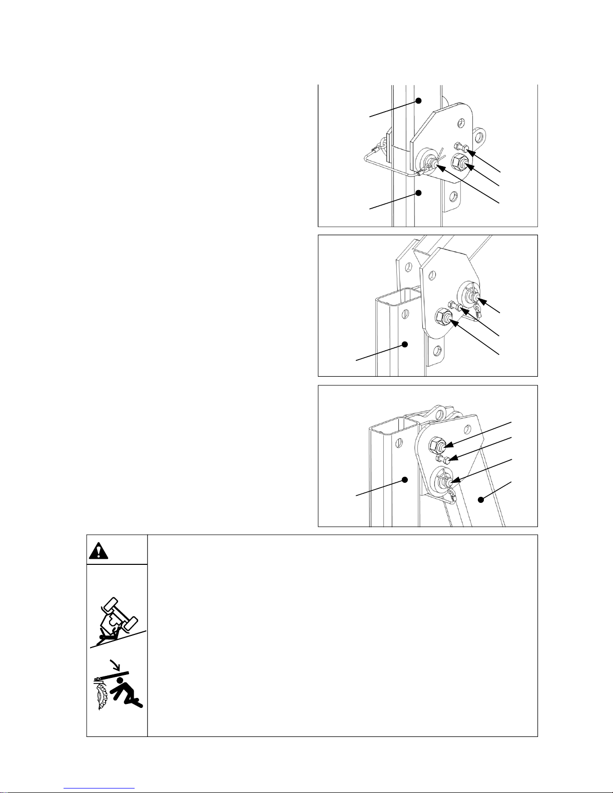
z How to fold the safety frame.
1. Loosen the safety frame bolts②④and nuts
(both sides) loosely. (Do not unscrew them
completely)
2. Remove the pins③ on the both side and fold
down the safety frame backward.
- Be careful of the possibility that your head, hand
and shoulder might be hurt by sudden folding
result from the weight of the safety frame.
3. Depending the position of the upper frame ⑤,
two positions are available on the lower frame
①. When folding the upper frame ⑤ fully, use
the lower side hole of the lower frame ① .
4. Set the holes of the frame ① and ⑤ in line, and
put the pins③ into the hole to fix the safety
frame and apply the snap pin.
5. Fasten the bolts②④and nuts (both sides)
tightly.
z When standing the safety frame up, follow the
same procedure.
z When the upper safety frame ⑤ is fully folded,
check the upper limit of 3-point linkage.
(4) Roll-Over Protective Structure (ROPS)
① Foldable Safety frame (Roll-bar type)
Warning
▶ Do not change or disassemble the safety frame arbitrarily for safety.
▶ Unless the safety frame is applied correctly, it may cause a serious acciden t on
tractor when being overturned.
- Be sure to stand the safety frame up completely and assemble the bolts, pins and
nuts in correctly.
▶ In case of folding the safety frame.
- Do cooperate with more than 2 people when folding or standing up the safety
frame as it’s heavy.
- Be careful not to be injured by sudden folding, which might occur when folding or
standing up the safety frame, results from its weight.
- Do not wear seatbelt when the safety frame is folded down.
- Do stand the safety frame up again as soon as the work is finished.
①
②
③
④
⑤
①
②
③
④
⑤
①
②
③
④

3 -1
3. Instruments and Controls
3-1. Instrument panel and Front controls
Important to owner , read carefully
Brake pedal
Turn signal
light switch
Joystick lever
(See section 3-3)
Instrument panel
Key switch
Throttle lever
HST pedals
HST type
Parking brake lever
Light switch
with hazard warning
light switch
PTO switch
Cruise control switch
3 -2
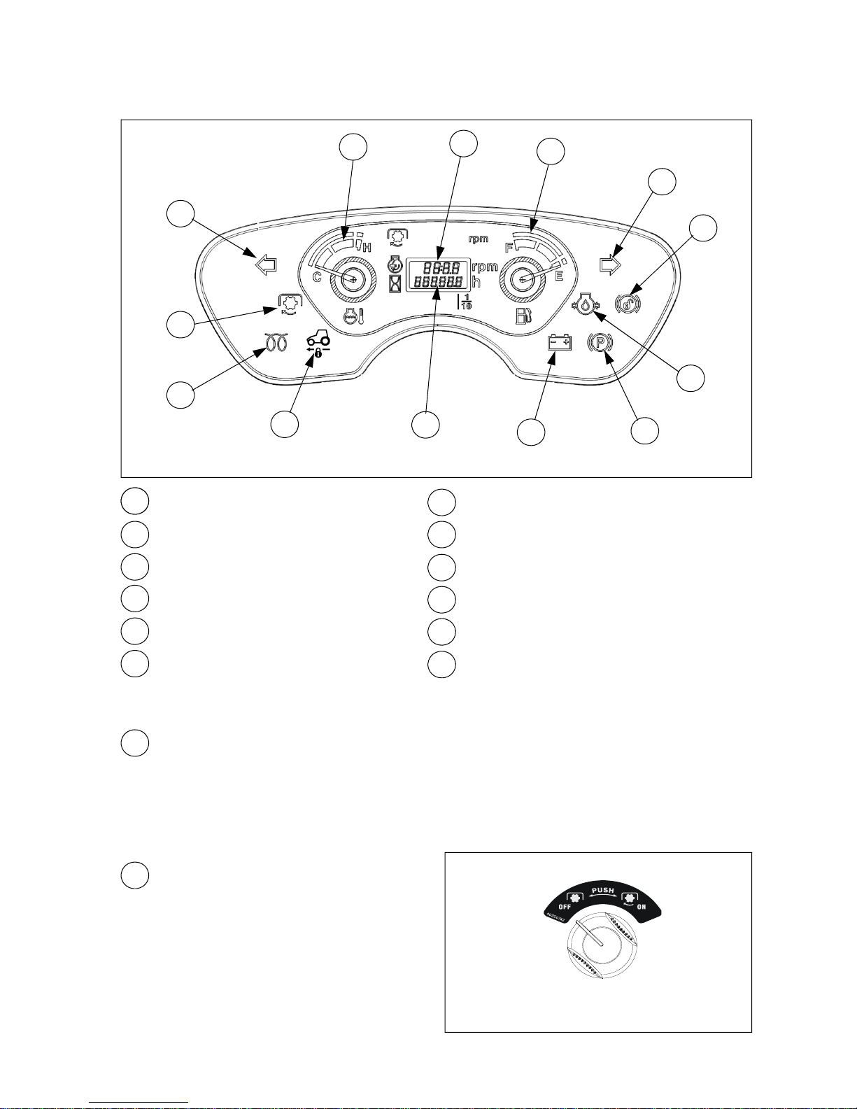
(1) Instrument panel
1
2
6
7
8
9
10
11
12
3
4
5
21
Turn signal indicator (Left / Right)
3
Cold start aid indicator
2
PTO operation indicator
4
Cruise drive indicator
5
Engine coolant temperature gauge
6
Tachometer
7
Hour meter
8
Fuel level gauge
9
Battery charging indicator
12
Engine oil pressure indicator
10
Parking brake indicator
11
Brake pedals not latched indicator (Not used)
1
Turn signal indicator (Left / Right)
z When turning the turn signal light switch to the
left/right direction, the front/rear turn signal
lights are blinked. At this time, this indicator
shall blink simultaneously.
1
2
PTO operation indicator
z When turning PTO switch ON while the engine
is running and PTO lever (if fitted) is engaged,
the PTO shaft shall rotate and this indicator
shall be turned on.
PTO switch
540/2933

3 -3
3
Cold start aid indicator
z When turning start-key switch to “Preheat”
position, this indicator shall be ON.
z When turning start-key switch to “Start”
position, this indicator shall be ON as well.
4
Cruise drive indicator
z This indicator shall be ON when pressing the
cruise control switch for applying cruise drive.
5
Engine coolant temperature gauge
z This gauge indicates the temperature of engine coolant.
z The closer the needle approaches “H”, the higher the temperature of engine coolant is.
z If the needle of engine coolant temperature gauge indicates red zone, Stop the engine
immediately and check the engine cooling system. (coolant, radiator screen, fan belt, …)
z The radiator and coolant is very hot. When checking the coolant level, comply with instructions of
the section 5 “Maintenance and Lubrication” in this manual.
6
Tachometer
z Tachometer shows running engine speed. (revolutions per minute)
7
Hour meter
z The number 0005.3 in hour meter shows that the tractor has been used for 5.3hours.
(5hours and 18minutes).
z This indicator shall be ON when turning the key
switch to ON position, and shall be OFF after
starting engine.
z If not, contact your authorized dealer for
checking electrical charging system.
9
Battery charging indicator
z This gauge indicates the remaining amount of
fuel. If the needle indicates “E”, fill the fuel tank
immediately
8
Fuel level gauge
65
3 4 7
8
9
540/2933
540/2933

3 -4
(2) Key switch
z “Preheat” – Preheat (Cold start aid)
z “OFF” – Engine stops, Power off
z “ON” – Power on
z “Start” – Engine start up
▶As soon as engine starts, turn the ignition key to “ON” position immediately. If not, it
may cause damage to starter motor.
▶If the tractor is not in use, the ignition key should be removed.
Caution
Key switch
Preheat
OFF
ON
Start
z This indicator shall be ON when turning the
key switch to ON position, and shall be OFF
after starting engine.
z If not, contact your authorized local dealer for
checking the engine lubrication system.
12
Engine oil pressure indicator
z This indicator shall be ON when pressing
brake pedal.
10
Parking brake indicator
11
Brake pedals not latched indicator
z This indicator is not used.
(3) Turn signal light switch
z This switch is used to give information to other
vehicles when turning to the left or right.
z If turning the switch to clockwise, the right turn
signal lights are blinking.
If turning the switch to counter-clockwise, the left
turn signal lights are blinking.
▶ When chang ing the lane or
direction on the road, operate
the turn signal lights to inform
other vehicles of your direction.
Caution
Turn signal light switch
Right
Left
Light switch
10
12
11
540/2933

3 -5
▶ When passing with other vehicles in the opposite lane at night, turn the headlights
to low beam not to disturb oncoming cars.
Caution
(4) Light switch
- U.S.A version
z OFF – Instrument panel and all lights are OFF.
– Instrument panel, sidelights and
hazard warning lights are ON.
– Instrument panel, sidelights and
headlights are ON.
(use when working)
– Instrument panel, sidelights, headlights
and hazard warning lights are ON.
(use when driving)
Light switch
- U.S.A version
z If turning the light switch ① by one step to the
clockwise, all hazard warning lights are blinked.
z When turning the light switch to “Low beam”
position, the hazard warning light is automatically
turned on.
▶ If you use the hazard warning lights for a long time, it may cause a increase of
electrical consumption. Do not use the hazard warning lights for a long time.
Notice
①
②
(5) Hazard warning light switch
Light switch

3 -6
(6) PTO switch
z To operate the independent PTO, comply with
the instruction as below.
1. Start engine and place the PTO select lever to
desired position.
2. Put the PTO switch to ON position.
3. To stop the PTO temporarily, push down the
PTO switch to OFF position.
4. To change the PTO gear lever (if fitted), make
sure to push down PTO switch to OFF position.
▶ To start engine, the PTO switch must be placed to “OFF” position.
▶ Before connecting or checking the implement, place PTO switch to “OFF” position.
▶ PTO shaft rotates even if the tractor moves backward. Pay attention to the
surroundings to prevent an accident.
▶ Do not engag e the PTO with the engine running at high speed. Sudd en
engagement can cause damage to some implement and tractor. Engage the PTO
at low rpm, and then raise engine speed to rated rpm.
Warning
ON : Push and Turn
OFF : Push
OFF
ON
PTO switch

3 -7
(7) Brake pedal
z The brake pedal for HST models is located at
the left-hand side of the front console.
z To stop the tractor, release the HST pedals. As
the HST pedals are returned to neutral position,
the tractor shall be stopped.
z This brake system is designed for parking brake
or emergency stop only. Do not use this brake
pedal for service brake.
z If 4WD is engaged, the braking force is applied
on front and rear wheels.
Brake pedal
Caution
▶ For HST models, when releasing HST pedals, the pedals shall be return to neutral
position and HST brake begins to work. But, you have to press this brake pedal
additionally in an emergency state.
▶ DO NOT ride your foot on the brake pedal while driving. If so, it may cause failure
of the brake device.
Parking brake lever
PARK
Release
Caution
▶ DO NOT drive the tractor while the parking brake is engaged. It may cause
damage to the brake or parking brake device.
(8) Parking brake lever
z To apply parking brake, press the brake pedal,
and lift the parking brake lever upward to engage
the parking brake ratchet.
z Release the brake pedal slowly with checking
the slippage of the tractor.
z To release the parking brake, press the brake
pedal little bit harder, and then the parking brake
lever shall be released by spring.

3 -8
▶ Set the engin e speed over 1500 rev/min for stability of hydraulic system while
driving or working.
Notice
(9) Throttle lever
z It is used to set or change the engine speed.
Low speed : Pull It backward
High speed : Push it forward.
z When using the throttle pedal, the throttle lever
must be placed on LOW speed.
Throttle lever
(10) HST forward / reverse pedal
(HST type)
z Press the HST pedal forward to drive tractor
forward.
z Remove foot from the pedal to stop the tractor.
As the pedal returns to neutral, the tractor shall
be stopped.
z The tractor speed is depending on the HST
pedal displacement.
z When reversing the tractor, press the HST
reverse pedal.
warning
▶ Press the brake pedal to stop the tractor at high speed. Even if the HST pedal(s)
become to be neutral, it takes long distance to stop the tractor at high speed.
▶ Do not sudden ly press/release the HST pedal(s) to avoid the impact of the
start/stop.
HST forward pedal
HST reverse pedal
Caution
▶ To prevent serious damage to the HST unit, do not arbitrary adjust the stopper
bolts related to the HST pedal stroke and linkage system.

3 -9
(1 1) Cruise control switch
(HST type)
z It is used to maintain the forward speed
constantly in case of HST models.
z For cruise drive, press down the symbol part of
the cruise control switch in the state of pressing
the HST forward pedal. And then, the HST pedal
shall be fixed and the tractor can drive forward
with constant speed.
z To quit the cruise drive ;
1) Press the brake pedal down or
2) Press down the non-symbol part of the cruise
control switch. And then, The HST pedal returns
to the neutral position and the cruise drive shall
be quitted.
▶ During the cruise drive, do not press down the HST reverse pedal to release the
cruise drive or to reverse the tractor. After quitting the cruise drive as above
described, press the HST reverse pedal.
warning
Cruise control switch

3 -10
Important to owner , read carefully.
3-2. Left / Right-hand side Levers and Pedals
HST type
Range gear
shift lever
4WD lever
Differential lock
pedal
PTO select lever
Electric power
socket
See section 3-3

3 -11
▶ When driving on the road, disengage the 4WD. If not, it may cause damage of
drive line and serious accident. After working, before coming out from the field,
select 2WD.
▶ When driving the tractor at high speed while the 4WD is engaged, sharp steering
may cause a accident.
(2) 4WD lever
z Stop the tractor completely before operating the
4WD lever.
z Push the lever forward to engage the four wheel
drive(4WD).
z Pull the lever backward to disengage 4WD.
z Four wheel drive (4WD) is effective for the
followings.
- When traction is needed in plow ground.
- When working on slippery ground.
- When working with tiller on hard ground.
- When crossing a ridge
(1) Range gear shift lever
z Low speed, neutral and high speed is available.
▶ Before operating range gear
shift lever, HAVE TO STOP the
tractor completely.
Caution
Range gear shift lever
Caution
High
Low
4WD lever
2WD
4WD

3 -12
(4) PTO select lever
z It is used to select the Middle PTO and/or REAR
PTO. If placing the lever as below;
REAR : Rear PTO shall only rotate.
MID+REAR : Middle PTO and rear PTO shaft
shall rotate together.
MID : Middle PTO shaft shall only rotate.
z For PTO shaft speed, refer to the section 6,
“Dimension and specification” in this manual.
z Before starting engine, place the PTO select
lever on “REAR” position. If the lever is placed
on the other position, you can not start the
engine, due to safety interlock system.
▶ After placing PTO switch in OFF and PTO shaft has been stopped completely, shift
the PTO select lever.
▶ If the PTO select lever is NOT engaged smoothly, lift up and down the rear
implement to align the drive shaft.
Caution
(3) Work light (optional)
z There is a switch to turn on the rear work light.
z ON - place the switch to the right direction and
the work light shall be ON.
z OFF - place the switch to the left direction and
the work light shall be OFF.
▶When driving on the road at night, do not let the rear work light stay ON position. It
may cause a disturbance to the driver of the following car.
Caution
OFF
ON
MID
REAR
MID+REAR
PTO select lever

3 -13
(6) Differential lock pedal
z If the tractor cannot go forward as one side rear
wheels are slipping, depress the clutch pedal
then press the differential lock pedal.
z Differential lock is effective for working on
slippery ground.
z If engaged, both rear wheels will rotate at equal
speed. So, It disturbs steering operation and you
cannot turn.
▶ Do not turn the tractor while the differential lock is engaged.
▶ Do not use the differential lock while driving on the road.
▶ Stop or drive slow the tractor before engaging the differential lock.
Warning
z Take your foot off the pedal to release the
differential lock. If the traction gap of the rear
wheels is reduced almost, the differential lock is
released automatically.
z If the differential lock does not disengaged
automatically, depress one-side brake pedal (if
fitted) slightly for a second, and/or turn the
steering wheel left and right after stopping
tractor .
Differential lock pedal
Differential lock
(5) Electrical power outlet socket
Electric power
outlet socket
z This is used to withdraw the electric power for
charging of the cigarette lighter jack or cellular
phone.
z In case of using cigarette lighter jack (optional)
-If you push the cigarette lighter jack, the heating
coil generates heat and shall be used as
alternative of lighter.
z In case of using as power supply (12V)
-Use the cellular phone charger less 10A.
Caution
▶ When using a cigarette lighter jack, cares must be taken not to touch the heating
coil. The heat generated coil is very hot and may cause the danger of a burn.

3 -14
3-3. Hydraulic system
(1) Safety precautions
z Hydraulic oil leaking under pressure can penetrate the skin and cause infection or other injury. To
prevent personal injury, comply with as below.
-. Relieve all pressure before disconnecting hydraulic lines.
-. Before applying pressure, make sure all connections are tight and components are in good
condition.
-. Never use your hand to check for suspected leaks under pressure.
-. If injured by leaking fluid, get medical attention immediately.
z The hydraulic hoses and fittings on your tractor meet engineering specifications for the particular
function. When replacing damaged parts, use only manufacture authorized service parts.
z Care in hydraulic hose installation is a must:
-. Make sure pressure is relieved before starting installation procedure.
-. DO NOT kink or twist a hose, failure may occur. Properly route the hose.
-. Have a certified hydraulic technician install the hose.
-. Remove air from the hydraulic system after installing any hydraulic component.
z Periodically check hydraulic system for leaks or damaged parts - kinked, crushed, flattened, hard
blistered, heat cracked, charred, twisted, soft or loose covered hoses and fittings.
z DO NOT pull or apply external forces to the hose. The hose may fail and cause injury.
z Keep all persons away from the working area. If a hose fails, mechanisms controlled by fluid power
can become hazardous. Lifted mechanisms can fall to the ground, steering system may fail, etc.
z Stay clear of a pressurized hose assembly that has blown apart. Hose fittings can be thrown off at
high speed and a loose hose can whip around with great force.
z Hydraulic oil can reach high temperatures. Allow fluid to cool before servicing the system.
z Vibration can reduce hose service life. Make sure all retaining clamps and/or devices are secured .
z Environmental conditions can cause hose and fittings to deteriorate. Inspect hydraulic hoses
periodically. Replace worn or damaged hoses and fittings.
Warning
▶Before removing hydraulic pipes or hoses and other parts, make sure to check that
hydraulic pressure is relieved completely. The leaks of pressurized oil can cause a
fatal physical injury.
▶Use proper protection equipments, before servicing hydraulic system.
▶Before connecting or disconnecting the hydraulic quick coupler, lower the
implements to the ground, and check that hydraulic pressure is relieved.
z Before checking or repairing the hydraulic system, make sure the engine is stopped, and all the
transmission gears are in neutral, and lower the implements to the ground.

3 -15
▶If the engine stops, the operation of steering wheel becomes hard to turn and
causes steering not to work. But this does not mean a failure.
▶If you turn the steering wheel while driving, the steering wheel does not return back
automatically.
Notice
(2) Steering system
z The hydraulic steering system controlled by fluid power provides you more convenience to operate
the steering wheel.
z Notices when using the steering system.
1. If there is too much of a load in front loader bucket, it could be difficult to operate the steering wheel.
In this case, reduce the size of the load.
2. After turning the steering wheel fully, do not turn the steering wheel to the same direction again. As
the unnecessary force is applied, this could damage to the steering system. Especially, DO NOT
operate the steering wheel excessively. If the front wheel mired in a ditch. In this case, the rim could
be affected and damaged.
3. If it sounds abnormal when operating the steering wheel, this means that there is some air in the
steering components and line. In this case, turn the steering wheel to the left and right fully and hold
it for about 5 seconds, and the air shall bleed out and the abnormal noise shall disappear. If it’s not
cleared, contact your authorized local dealer for repair.
4. When starting engine in cold weather, an abnormal noise may occur. In this case, warm up the
tractor before using to reduce the oil viscosity.
5. If you use the tractor for a long time while turning the steering wheel fully, the oil temperature will
increase which may cause the reduction of the product life or the failure of hydraulic and steering
system.

3 -16
(3) Hydraulic lift control
Position control lever
Down speed
control knob
Mid mower height
adjustment knob
① Position control
z The 3-point linkage can go up/down by using
the position control lever as below.
1. Push the position control lever forward, the 3point linkage goes down.
2. Pull the position control lever backward, the 3point linkage goes up. The raising speed is
depend on the engine speed. If it does not raised
at the low rpm, increase the engine speed.
3. If releasing position control lever, the lever goes
to neutral automatically and the 3-point linkage
shall be stopped.
Position control lever
Down
Up

3 -17
② Down speed control knob
z Turn the knob to the clockwise to lower the
implement slowly and to the counter-clockwise
to rise speed faster. If turning the knob clockwise
to lock, the implement is fixed and even If
lowering down the position control lever, the
implement can not be lowered down.
- Tiller : Slow in down speed.
- Plough : Fast in down speed.
z When working in hard ground, lower down the
implement slowly to avoid the rebound of the
implement.
▶When driving on the road, replacing tiller blades or removing grass around the tiller
blades, turn the down-speed control knob clockwise slightly to lock.
▶DO NOT OVER TIGHTEN (Control knob could lock valve in up position.)
Warning
Fast
Slow & Lock
Down-speed control knob
(4) Mid mower height adjustment knob
z This is used to adjust the height of the mid
mower while working.
z At first, lift up the 3-point linkage and mid mower.
z If rotating the knob counter-clockwise, the height
of the mid mower shall be lowered, and
otherwise the height shall be lifted.
z Lower down the 3-point linkage and mid mower.
Low
High
Mid mower height adjustment knob
▶Do not try to turn the mid mower height adjustment knob clockwise without lifting
the position control lever.
Notice

3 -18
(5) Remote control lever and Quick coupler (optional)
z This is used to operate the hydraulic cylinder and/or motor of the implement attache d to the tractor
by the hydraulic oil pressure.
z If you lift up the remote control lever, the hydraulic pressure works to the upper coupler, and the
lower coupler is connected to the drain.
z When releasing the lever, the remote control valve is returned to neutral position.
z After connecting and preliminary operating the hydraulic equipment, check again transmission oil
level of the tractor.
Remote control
lever`
UP
DOWN
Quick coupler
Remote control valve
From pump
To hyd. housing
To drain (oil tank)
When lifting up
When pushing down
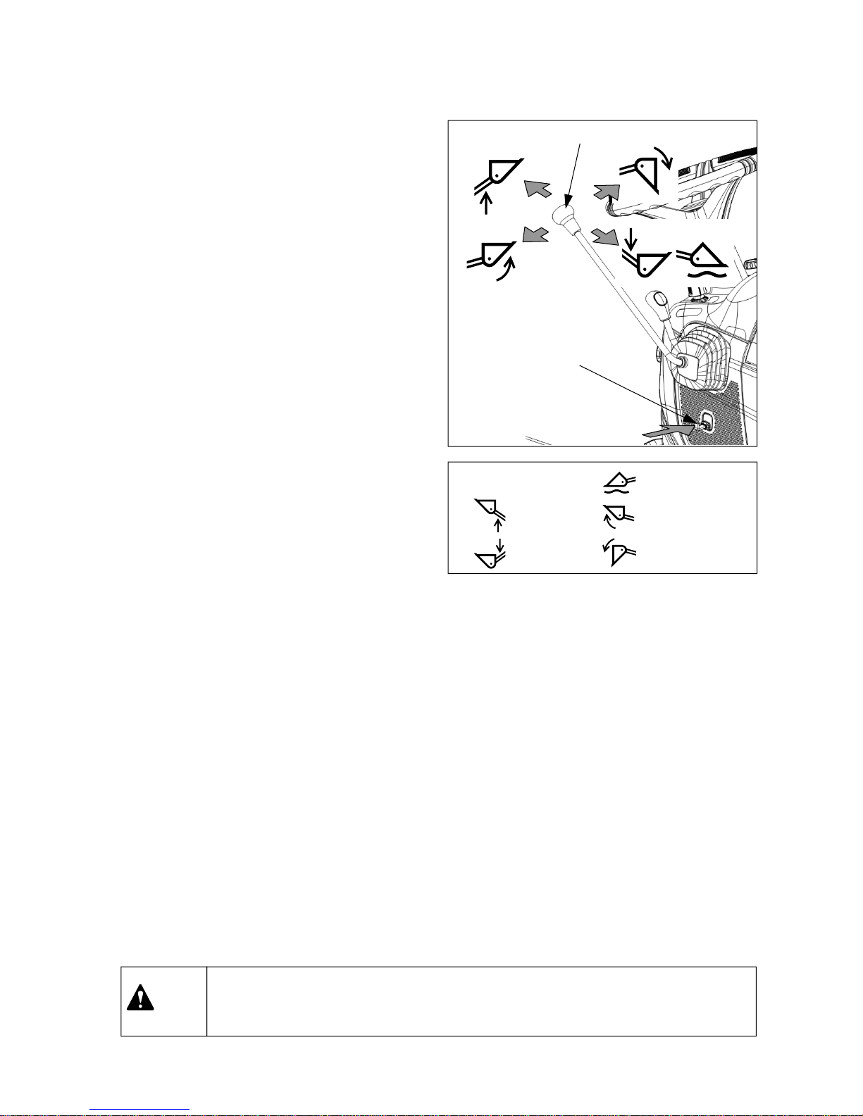
3 -19
Loader up
Loader down
Bucket up
Bucket dump
Bucket floating
<Meaning of symbols>
▶To prevent accidents, push and lock the locking lever when you do not use joystick
lever.
Warning
Locking lever
(safety device)
Joystick lever
Lock
(6) Joystick lever (if fitted)
z Remote joystick lever helps to operate front-end
loader comfortably.
z Joystick can be operated at 4 directions as
shown in the right figure.
z If you move joystick diagonally, boom and
bucket may be operated at the same time. In this
case, less loaded cylinder may be moved first.
z When you want to float bucket, lower the loader
and push forward the lever at floating position.
After finishing work, pull the lever and place it in
neutral position.
z Locking lever shown in the right figure is used to
lock the joystick lever.
- Pull from the joystick : Unlock
- Push to the joystick : Lock
z For further information, See section 4-4-(8),
“Using Front-end loader” in this manual.

3 -20
(7) Hydraulic System Diagram
HST type
1. Hydraulic oil filter
2. Hyd. Pump & valve assembly
3. Steering unit
4. Steering cylinder
5. Independent PTO valve
6. HST filter
7. Front loader valve (optional)
8. Hydraulic lift control valve
9. Down speed control valve
10. Lift cylinder in hydraulic housing

4 -1
▶ Check each part bef ore starting the
engine.
▶ Check if there’s anyone close to the
tractor before starting.
▶ Place all the levers and switches in
“NEUTRAL” or “OFF” position.
4. Operation and Work
4-1. Engine start and stop
(1) Engine start
Caution
3. Place the PTO
select lever on “Rear
PTO” position and
HST pedal in
NEUTRAL position.
HST type
Brake pedal
HST pedals
Throttle lever
Range gear
shift lever
PTO select
lever
PTO switch
7. Check if engine oil pressure
indicator and battery charging
indicator are OFF. If not go OFF,
stop the engine and check the
problem.
8. Run engine a few
minutes to allow
engine oil and
transmission oil to
warm up.
6. Turn key switch to start
position. As soon as the
engine starts, release
key switch to ON
position.
2. Place the range gear shift lever
in NEUTRAL, and PTO switch
in OFF.
1. Sit in the driver’s seat
and apply the parking
brake lever.
4. . Turn key switch to
ON and check if the
battery charging
indicator and engine
oil pressure indicator
are ON.
5. Turn the key switch
to “Preheat” for
about 4 seconds
with checking if the
pre-heating indicator
is ON.
4 -2
(2) Start in cold weather
z Push the throttle lever to the middle position of full throttle.
z Start the engine after operat ing the cold start aid for about 4 second s.
z If engine begins to run, carry out warming up for 5~10 minutes at 1500 rpm.
z Use the engine oil for winter in cold weather. Refer to “Lubricants and Capacity” at the end of this
manual.
z Use the diesel for winter when it is very cold weather. It is much easier to start engine.
Warning
Caution
▶ When storing the tractor in the cold weather, the battery must be removed and
stored in a cool and dry place where it is warm and is isolated from the children.
▶ Allowing engine to idle for a long time will waste fuel and cause a build up of carbon.
Caution
▶ Only start engine outdoors or in a well ventilated place, as the engine exhaust
fumes may cause sickness or death.
▶ To avoid an explosion, never use startin g fluid to start eng ine.
▶ Start the engine ONLY from the driver’s seat with placing all the transmission gear
shift levers in neutral.
▶ DO NOT start the engine by shorting across the terminals of start motor. If the
engine starts and the tractor moves suddenly, it may cause a serious injury or death
.
▶ If HST pedal is not in neutral or PTO switch is not “OFF”, the engine does not
start even if turning the key switch to start position.
▶ Do not opera te start motor more than 10 seco nd s. If engin e doe s not start, wait
for 1~2 minutes before restarting.
▶ When the engin e is running, DO NOT turn the key switch to “Start” position. It
may cause the failure of start motor.
▶ In the cold weather, carry out the warming up. If you use the tractor in the state
that the engine does not reach the normal temperature, the engine life shall be
reduced.

4 -3
(3) Engine stop
z Pull the throttle lever backward to reduce the
engine speed and turn the key switch to “OFF”
position. The engine shall be stopped.
z Remove the ignition key after stopping engine.
▶ When stopp ing the eng ine after hea vy work, run the engine for 1~2 minutes at low
speed. If you stop the engine suddenly, the engine life could be shortened.
Caution
Throttle lever

4 -4
4-2. How to drive and stop
(1) How to drive
7. If pressing the brake pedal or turning off the
cruise control switch, the cruise control
mode shall be quitted.
6. If necessary, press down the symbol part of
the cruise control switch fix the driving speed
constantly.
1. Pull the position control lever to lift the
implement up after starting engine
2. Set engine speed at 1500 rev/min.
3. Place the range shift lever to the suitable
position.
4. Press the brake pedal and release the
parking brake.
5. Press the HST pedal slowly forward or
backward to move the tractor.
▶For HST model, there is a switch to control engine cut-off for driver’s safety. If the
operator leaves the driver’s seat without proper action for safety, the engine shall
be stop automatically. (For further information about seat, see page 2-2)
▶ When you drive HST type tractor, run the engine speed more than 1500 rev/min
for stability of hydraulic system.
▶ Press down the HST pedals slowly to prevent the sudden start of the tractor.
Notice
HST type
Range gear lever
Throttle lever
HST pedalsBrake pedal
Position control lever
Down
Up
Cruise control switch

4 -5
(2) Changing speed
HST type
z Move throttle lever forward to increase the
driving speed.
z Press down the HST pedals slightly or fully to
control the driving speed.
z Set driving speed properly depen ding on the
road condition with range gear lever.
z The range gear shift lever must be operated in
the neural state of HST pedals, and after tractor
has stopped completely.
Throttle lever
HST forward pedal
HST reverse pedal

4 -6
3. Apply the parking brake after pressing the
brake pedal.
1. Take a foot off from the HST pedals and
press the brake pedal at the same time.
HST type
2. Turn the key switch to “OFF” position.
Do not press the HST pedals before the
engine stops completely.
(3) Emergency Stop
Brake pedal
Parking brake lever
PARK
Release

4 -7
(4) Stopping tractor
1. Take a foot off from the HST pedal, and
press down the brake pedal. Place the range
gear shift lever in NEUTRAL and PTO switch
to OFF position.
3. Engage the parking brake lever after
pressing brake pedal, and take foot off from
the brake pedal slowly.
2. Pull throttle lever backward to lower the
engine speed.
Turn the key switch to “OFF” position.
HST Type
Range gear lever
PTO switch
HST pedalsBrake pedal
Parking brake lever
PARK
Release

4 -8
(5) Driving tractor on the road
z When facing downhill, DO NOT place the gear lever in “Neutral” position.
z When driving the tractor on a unpaved road by attaching an implement to 3-point linkage, place the
gear lever to low speed and DO NOT lift the implement up to the highest position. When the tractor
bumps an obstacle, it may cause the jolting of implement and the failure of hydraulic system.
(In this case, place the position control lever on ¾ rising position of full stroke for safety.)
▶ Avoid a sudden start, sudden brake and sharp turn.
▶ DO NOT allow people on the tractor or on other implements.
▶ DO NOT place the baggag e on the tractor or implement.
▶ Place PTO select lever in NEUTRAL (if fitted) and put the PTO switch in OFF
position.
▶ DO NOT use the differential lock and four wheel drive (2WD use only).
▶ When traveling with implement on rear 3-point linkage, tighten the stabilizer to
avoid lateral movement.
▶ When traveling with implements installed , turn slowly by wide turnin g radius.
▶ While traveling, DO NOT ride your foot on the clutch pedal (if fitted) or brake
pedal(s).
▶ While traveling, DO NOT ope rate any implement such as tiller, loader etc.
Caution
DO NOT USE DIFF-LOCK

4 -9
(6) Parking
z Stop the tractor on a level surface, not on a slope.
z Disengage PTO and place all the transmission
gear levers in NEUTRAL position and apply the
parking brake.
z Lower down the implements on the ground .
z Stop the engine and remove ignition key.
z Before you leave the operator’s station, wait for
engine and all the moving parts to stop.
▶If it is necessary to park the tractor on a slope, furthermore with loaded trailer, the
tractor may roll down, even though the parking brake is applied. In this case, apply
the gear in low speed and apply the chocks or blocks to all the tire.
- HST Type : place the range gear shift lever to the lowest speed.
Caution
Caution
▶DO NOT depart from the tractor with the transmission gear placed in neutral and
the parking brake is not applied. In neutral position, the tractor may roll. Apply the
parking brake at all times before leaving the tractor.

4 -10
4-3. How to handle new tractor
(2) Notices in handling new tractor
z To get the best performance, comply with the following instructions.
- DO NOT start or stop the tractor suddenly.
- DO NOT carry out heavy loaded work and DO
NOT increase the engine rpm to high speed
suddenly.
- Despite warm temperature outside, carry out
warming up the engine for approximately 5
minutes at 1500 rev/min
(1) Check points
※ For new tractor, the followings must be checked once aga in even thou gh there was sufficient quality
management, inspection, regulating of each part in the factory.
z Appearance check
- Is there any damage while transporting?
z Engine cooling system check
- Is there anti-freeze solution in the radiator? And any leakage?
z Fuel system check
- Is there any leakage of fuel in the fuel system?
z Oil level check
- Is there optimal oil amount in each part ?
z Electric system check
- Is there any cut-off or any other problem in the wiring?
- Is there any problem to operate the instruments?
- Is the state of battery charging sufficient?
z After using first 50 hours,
- Replace the engine oil filter and hydraulic oil filters after first 50 hours of work, and check each
part of your tractor as reference of chapter 5-4. “First 50 hour check” in this manual.
- If possible, contact your authorized local dealer for “First 50 hour check”.

4 -11
(1) 3-point linkage
4-4. Attaching Implement
Warning
▶Before attaching/detaching implement, place PTO switch in OFF position and PTO
gear lever in neutral position, and apply the parking brake.
▶When attaching/detaching implement, make sure to assemble and tighte n the
connecting parts correctly.
▶If the tractor is used to tow heavy loads, always use the approved drawbar or hitch
to avoid injury. Never connect to lower link or upper link of 3-point linkage. If not, it
may cause tipping or turnover.
▶DO NOT connect the implements that require more power than can be generated
by your tractor.
▶Never stand between implement and tractor when connecting implement.
▶DO NOT change the setting pressure of the relief valve arbitrarily to increase the lift
capacity of the 3-point linkage. It can cause fatal damage to the hydraulic system.
z When attaching the implement, comply with the followings.
1. Set the implement upright on a level surface and approach the implement in reverse.
2. Stop the tractor on attaching position and apply the parking brake.
3. Connect the lower link(3) to implement and insert firmly the lock pin. (left, right)
4. Connect the upper link(5) to implement and insert firmly the lock pin. Wide adjustable range of the
upper link provides you easier attachment.
5. Fix the implement firmly with stabilizer(2).(left, right).
①
④
③
⑤
②
⑥
⑦
① Lift rod (LH)
② Stabilizer
③ Lower link
④ Lift rod (RH)
⑤ Upper link
⑥ Lift rod pin
⑦ Upper link pin
⑧ Lower link pin
⑧

4 -12
① Upper link installation and
adjustment
z Adjust the upper link ① depending on the
implements.
z Length of the uppe r link ① can be adjusted by
turning the grip ②.
z Fasten the lock nut ③.
z Adjusting range : 15.7 ~ 29.5 inch.
▶ Insert the snap-pin ⑤ firmly to prevent the upp er link pin ④ from being escaped.
Notice
② Adjustment of the lift rod’s length
z Lift rod (RH) can be adjusted by loosening the
lock-nut ②, and turning the body ①.
z After adjusting, tighten the lock-nut ② again.
③ Adjustment of stabilizer ’s length
z The length of the stabilizer can be adjusted by
turning the handle ② , after removing the fixingpin ①.
z After adjusting, insert the fixing-pin ① again.
▶ Adjust the lateral swinging
clearance of the implement to
be within 20~40mm (0.8~1.6 in).
Notice
②
①
④⑤
③
①
②
①
②

4 -13
④ Reference of Implement installation part
19
(0.74)
A
B
C
(Max)
GH J L N
CAT.1
19.3
(0.75)
683
(26.8)
4.5
(0.18)
39
(1.53)
35
(1.53)
22.4
(0.88)
22
(0.86)
44.5
(1.75)
69
(2.71)
76
(2.99)
44
(1.73)
Unit : mm
(unit : inch)
D
(Min)
K
E
(Max)
F
(Min)
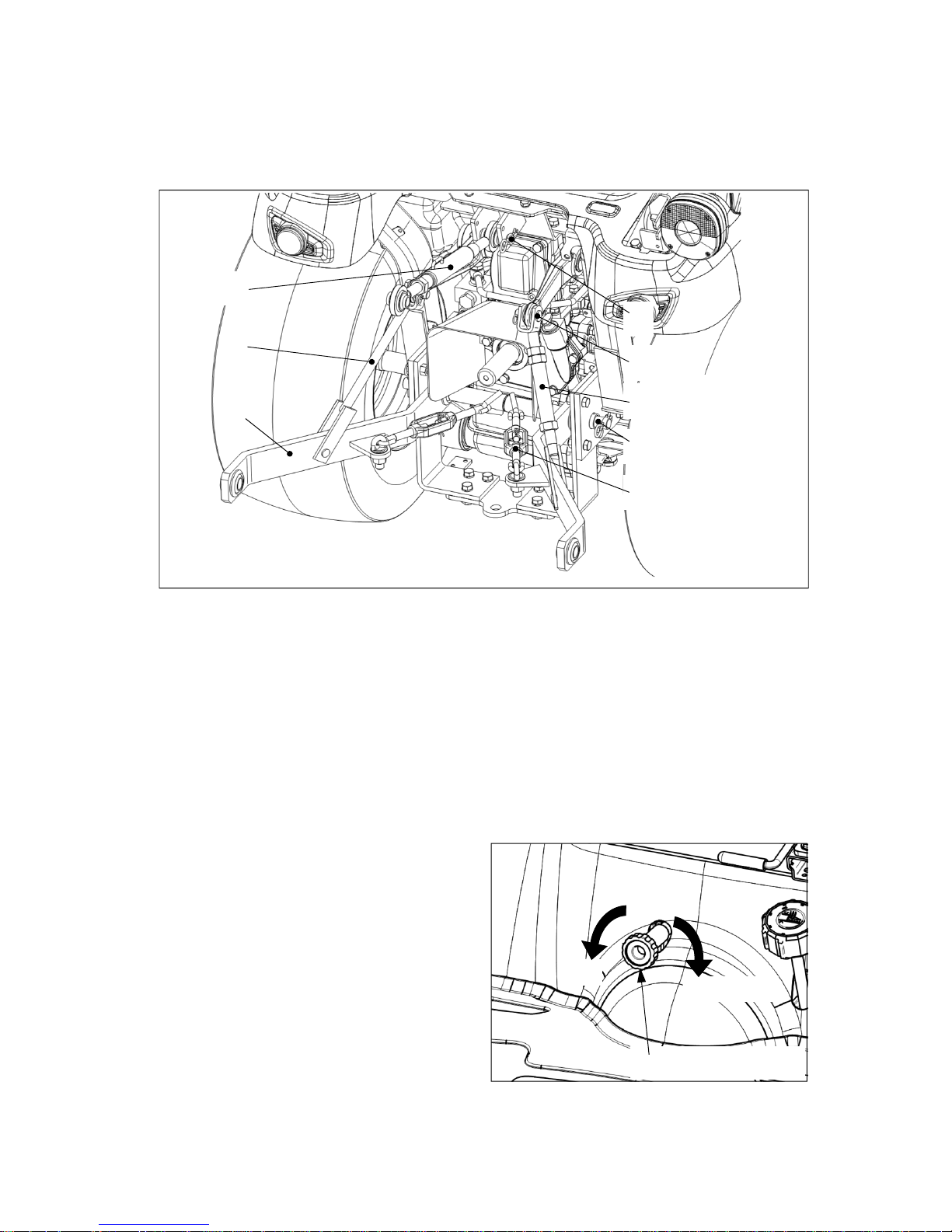
4 -14
z When driving the tractor without attaching implement, comply with the followings.
1. Fix upper link ⑤ or remove it.
2. Connect stabilizer ② to the lower link ③ to avoid lateral movement of the lower link.
z If the 3-point linkage is not necessary, remove it as follows.
1. Remove upper link pin ⑦, and detach the upper link ⑤.
2. Detach fixing parts between lift rod ①,④ and lower link ③ while holding lower link tightly.
And, put down the lower link.
3. Remove the lift rod pin ⑥ and detach lift rod (LH) and lift rod (RH).
4. Detach the lower link ③ and stabilizer ② after removing the lower link pin ⑧.
⑤ Handling of the 3-point linkage
①
④
③
⑤
②
⑥
⑦
⑧
Fast
Slow & Lock
Down-speed control knob
z When using hitch/drawb ar, or driving on road, lift
up the 3-point linkage and fix it by turning the
down speed control knob to lock position.
① Lift rod (LH)
② Stabilizer
③ Lower link
④ Lift rod (RH)
⑤ Upper link
⑥ Lift rod pin
⑦ Upper link pin
⑧ Lower link pin
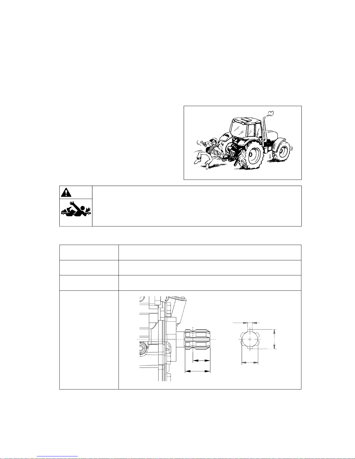
4 -15
(2) Power take-off (PTO) shaft
① Safety precautions
z When PTO shaft is rotating, NEVER APPROACH the shaft.
z Check if PTO shield is attached correctly. If the shield is removed or damaged, replace it with a new
one.
z Suitable Clothes & Protect Entanglement :
When checking or attaching implement to the
PTO shaft, wear tight fitting clothes and safety
equipment instead of loose or long clothes. Also,
slippers, high heel shoes are not suitable. Wear
the suitable clothes.
Warning
▶Do not approach the rotating shaft such as PTO shaft or cooling fan, especially,
with loose clothing and long clothes. The entanglement in rotating shaft can cause
serious injury or death.
▶Stop the engine and be sure PTO shaft is stopped before getting near it.
② Specification and Dimension of Rear PTO shaft
Rear PTO 1 speed gear (6T)
PTO / Engine speed 540 / 2933 rpm
Rotation direction Clockwise (When looking at PTO shaft end)
Shaft dimension
(Unit : inch)
(0.34 in)
(1.1 in)
(1 3/8 in)
(Teeth : 6T)
1.18 in
(1.71 in)

4 -16
Module : DP 16/32
Number of Teeth : 15T
(1.77 in.)
(0.94 in.)
(0.84 in.)
(0.98 in.)
MID PTO 1 speed gear (15T)
PTO / Engine speed 2500 / 2841 rpm
Rotation direction Counter clockwise (When looking at PTO shaft end)
Shaft dimension
(Unit : inch)
③ Specification and Dimension of Middle PTO shaft

4 -17
④ Attaching PTO drive shaft
z When connectin g PTO drive shaft to the PTO shaft and implement, make sure to check the fixing
status of the locking pins.
z When attaching implements with power take-off drive shafts, refer to the drawings as below.
z After installing implements,
- check the inclination of the PTO drive shaft,
- check the interference with PTO safety cover and other structure,
- check the effective engaging length of the PTO drive shaft according to the position of the 3-point
linkage.
z The stiff inclination of the drive shaft makes a loud noise and may cause a failure of the driveline.
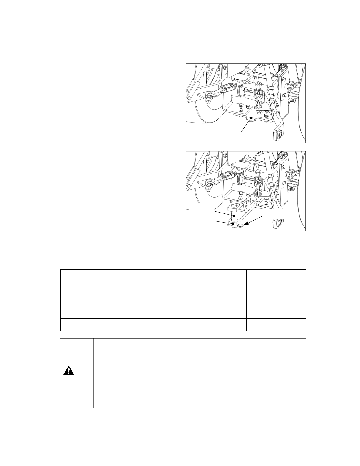
4 -18
(3) Hitch and Drawbar (optional)
z When attaching towing equipments, use the
hitch or drawbar. DO NOT use the 3-point
linkage or other parts. If so, the tractor could
turnover.
z When attaching towing equipments, do not
exceed the maximum permissible vertical and
horizontal loads.
Hitch
▶ Pulling from the tractor rear axle or any point above the axle may cause the tractor
to overturn. Use always the drawbar or hitch for pulling work.
▶ Do not tow equipment withou t brakes, weighin g more than twice the tractor weight.
▶ When locking the hitch or drawbar with pin after aligning to the towing equipmen t,
apply the parking brake and stop the engine.
▶ Before transp orting equ ipment on public roads, make sure you comply with your
local traffic regulation.
Caution
Hitch Drawbar (w/clevis)
Unbraked towable mass 800kg (1764 lb) 800kg (1764 lb)
Independently braked towable mass 1600kg (3527 lb) 1600kg (3527 lb)
Inertia-braked towable mass 1600kg (3527 lb) 1600kg (3527 lb)
Hydraulic or pneumatic braked towable mass N/A N/A
Hitch pin
① Hitch
z Vertical load : 400kg (882lbs)
z Horizontal load : 1600kg (3527lbs)
② Drawbar (w/clevis)
z It is used to tow the equipment having 2 axles.
z It is available to adjust the length of draw bar
(telescopic type) after removing snap pin and
lock pin in the right figure. After adjusting the
length, assemble the pins correctly.
z Insert the hitch pin and snap pin correctly after
attaching/detaching the equipment.
z Vertical load : 400kg (882lbs)
z Horizontal load : 1600kg (3527lbs)
Drawbar
Snap pin

4 -19
(4) 7-Pole connector (if fitted)
z The one of the standard 7-pole trailer connectors is provided and is mounted at the rear of the tractor.
The connections of the 7-pole connector (viewed from the rear of the tractor) are as follows;
z EC Version
Pin No. Function
1 Left turn signal light
2NA
3 Ground (Earth)
4 Right turn signal light
5 Side light
6 Brake light
7 Side light
z ASAE Version
Pin No. Function
1 Ground (Earth)
2 Working light
3 Left turn signal light
4 Brake light
5 Right turn signal light
6 License number plate light
7 Auxiliary

4 -20
(5) Technically maximum permissible mass
z When working with front loader or rear heavy loaded attachments installed to the 3-point linkage,
install ballast weights on the counter-part axle to maintain the front and rear weight balance of the
tractor. If not, front or rear axle can be strained by the overloaded weight.
z When working with the front loader, place the attached rear weight to the highest position and turn
the down speed control knob to the “lock” position.
z DO NOT exceed the total maximum permis s ibl e mass and/or permissible maximum mass on
each axle declared by manufacturer as below, even if the load capacity of the tire is sufficient.
z If the load capacity of the tires is lower than maximum permissible mass on each axle , the
maximum mass on each axle must be loaded under the load capacity of the tire.
Check the load capacity of the tires.
All models Remarks
Technically total maximum
permissible mass
1200kg (2646 lb)
It may depend on the load
capacity of the tires.
(See next page)
Front axle (*) 650kg (1433 lb)
Rear axle 840kg (1852 lb)
▶ Maximum permissible mass is measured with only the front or rear wheels on the
scales inclusive of ballasts and with mounted equipment in the raised position.
▶ Do not exceed the maximum permissible mass abov e and/or the load
capacity of the tires. Overloaded operation may invalidate the warranty.
▶ DO NOT change the setting pressure of the relief valve arbitrarily to increase the
lift capacity of the front loader or 3-point linkage. It can cause fatal damage to the
hydraulic system and front axle.
Caution
* includes front mounted equipment or loader in the raised position but without load in the bucket.
z Restrict operation : In case of driving speed does not exceed 8km/h (5 mph) and standard
front/rear wheel track (See page 6-1), intermittent maximum permissible load of the front axle can
be ;
810kg (1786 lb) for all models ; Have to check the load capacity of the tires. (See next page).

4 -21
(6) Tires and Load capacity
(*) 1 : Front axle, 2 : Rear axle
Axle No.
(*)
Tires
Standard tire air pressure
(kg/cm2)
Load capacity (x2)
(kg)
Maximum mass(es)
1
18x8.50-10 4PR
(Industrial)
1.5 (150 KPa, 22 psi) 750 (1653 lb)
1200kg (2646 lb)
2
26x12.0-12 4PR
(Industrial)
1.4 (140 KPa, 20 psi) 1620 (3571 lb)
1
18x8.50-10 4PR
(Turf)
1.5 (150 KPa, 22 psi) 750 (1653 lb)
1200kg (2646 lb)
2
26x12.0-12 4PR
(Turf)
1.4 (140 KPa, 20 psi) 1614 (3558 lb)

4 -22
(7) Adjusting Wheel tracks and tire replacement
z If the front wheel track is adjusted, check the
clearance between tires and tractor body case
by case. If necessary, the steering angle must
be adjusted.
(See page 4-25 in this manual)
z When adjusting rear wheel track, check the
radial and lateral clearance between rear tire
and tractor chassis as below.
- A : 15mm (0.6 in) (Minimum)
- B : 30mm (1.2 in) (Minimum)
▶ When adjusting the wheel track, pay attention to the direction of tire lugs. If it
shows “/\” shape when looked behind, it is correct.
▶ Actual settings may vary depending on the brand of the rim and type of tire.
Notice
▶The tractor wheels are very heavy. PLEASE BE CAREFUL.
▶When removing the wheels, proceed with extreme caution, use a suitable hoist and
specific equipment to move heavy parts.
Warning
“A”
“B”
FENDER

4 -23
① Safety precautions
z Multi-functional joystick lever provides you more
convenient operation for front-end loader.
z When operating the tracto r with front-end loade r,
the center of gravity of the tractor may be higher,
and the stability of the vehicle may be worse
than unattached vehicle.
-. DO NOT drive fast on a traffic load. The rolling
or tipping of the tractor can be happened easily.
-. When loading/unloading the bucket on a slope,
move the tractor straight against the slope.
-. DO NOT try to approach a stiff slope.
-. Attach the ballast weight on the 3-point linkage
to prevent the overload of the front axle, and to
improve the stability of the vehicle.
z When working with front-end loade r, the front
visibility of the tractor may be worse than
unattached vehicle. Have to observe people and
other vehicles around the tractor.
z DO NOT allow people to pass under the front-
end loader.
z DO NOT allow people to ride on the bucket.
▶After using the front-end loader, lock the joystick lever to prevent the accident.
(if fitted)
▶When leaving the tractor, lower down the front-end loader on the ground.
Warning
(8) Using Front-end loader (optional)
▶Have to strictly observe the following precautions;
- Do not lift the front-end loader to a height from which objects may fall or roll onto
the driver.
- Use always the correct attachment (grab forks, buckets.. etc) for the specific task
to perform and ensure that the load is securely kept in place.
Warning
Locking lever
(safety device)
Joystick lever
Lock
Loader up
Loader down
Bucket up
Bucket dump
Bucket floating
<Meaning of Symbols>

4 -24
② Connection of hydraulic hoses
z Refer to the following instruction for hydraulic
hoses connection.
z Boom lowering – coupler ①
Boom lifting ------ coupler ②
Bucket lifting ----- coupler ③
Bucket dump ----- coupler ④
z The thread specification of valve outlet ports,
pipe end adapter and quick coupler;
- valve outlet ports : PF 3/8
- pipe end adapters : PT 3/8
- quick couplers : ISO 5675 3/8”
z . Use suitable quick couplers for hose
connection. If possible, contact your authorized
local dealer.
z After connecting the hoses, start the engine and
check the leakage of the hydraulic lines.
z Check the transmission oil level after installing of
the front loader.
④
③ ②
①

4 -25
③ Attaching points for Front-end loader
z When attaching the front-en d loade r for all models, refer to the drawings as below.

4 -26
(9) Adjusting Steering Angle
z The adjustment of steering angle for this models is not available. Your tractor has fixed maximum
steering angle.
z Maximum steering angle : See section 6, “Dimension and Specification”.

4 -27
(10) Recommended Maximum Specification of Implements
No. Implements Specification MT122, MT125
1 Trailer Maximum vertical load See section 4-4-(3) in this manual
2 Mid mower Max working width 1524 mm (60 in)
3 Rear mounted mower Max working width 1524 mm (60 in)
4 Rear mounted sprayer Maximum weight 150 kg (331 lb)
5 Pulling type sprayer Maximum weight 800 kg (1600 lb)
6 Rotary Tiller Max tilling width 1280 mm (50 in)
7 Bottom plow Maximum width 110 0 mm (43 in)
8 Manure Spreader Maximum volume 800 kg (1600 lb)
9 Front grader Max working width 1400 mm (55 in)
10 Rear blade Max working width 1370 mm (54 in)
11 Front loader
Max lift capacity
(Bucket pivot point)
402 kg (886 lb)
12 Box blade Max working width 1280 mm (50 in)
13 Backhoe Max digging dept h 1978 mm (78 in)
14 Snow Blade Max working width 1370 mm (54 in)
15 Snow Blower Max working width 1370 mm (54 in)
z When attaching implements to the tractor, refer to the followings recommended as maximum
specification of each implement. DO NOT attach bigger implements than this specification. For other
implements, contact your authorized local dealer.

4 -28
4-5. Driving speed
z The driving speed of tractor or the revolution speed of PTO depends on the work, tire and ground
condition. For safety, operate the tractor at suitable speed .
z Table of driving speed (unit : Km/h -> Mile/h)
Note) Engine speed : 3000 rev/min, Dynamic load radius : 295mm (11.6 in).
HST Type
Range gear LOW HIGH
Forward
0 ~ 6.13 Km/h
(0 ~ 3.81mph)
0 ~ 14.65 Km/h
(0 ~ 9.10 mph)
Reverse
0 ~ 3.70 Km/h
(0 ~ 2.30 mph)
0 ~ 8.80 Km/h
(0 ~ 5.47 mph)

5 -1
z For safety, the hood must be closed and
correctly latched before operating the tractor.
z The hood is hinged at the front. A gas cylinder is
attached inside to support the hood for easy
access to the engine.
z To open the hood, push the hood opening knob
and lift up the hood.
z To close the hood, lay down the hood and push
it down slightly to lock position.
5-1. Access for maintenance
① Opening Hood
▶ After the engine has stoppe d complete ly, you have to open the hood for check.
▶ If you open the hood while the engin e is running, it can cause serious damag e by
the intended or unintended access to rotating shaft, pulley, V-belt, cooling fan of the
engine or engine application parts. PLEASE BE CAREFUL.
Caution
Hood opening knob
5. Lubrication and Maintenance
z The jacking points for maintenance is depending
on serviced parts case by case. Do not hesitate
to contact your authorized local dealer for asking.
z Do not use the front axle assembly or steering
linkage and cylinder for jacking point. These
components have some rotating pivots and/or
does not have enough structural strength.
z For general maintenance, use flat surface under
the engine frame end for jacking point, and
connect additionally hoist to the front towing
hook (if fitted) for safety.
z For rear jacking points, flat surface under the
rear axle housing is recommended, and
additionally use the top-link bracket and its pin
for lifting point after removing the top-link.
② Jacking points
Front jacking point
Front towing hook
(optional)
Rear jacking point
(both side)
▶ When lifting the rear of the
tractor, apply chocks to the slots
between front axle and engine
frame symmetrically to prevent
the rolling of the front axle.
Caution
PUSH

5 -2
HST type
9
23
4
12
19
14
20
16
7
6
10
11
3
21
8
17
2
z Periodic maintenance not only extends the service life of the tractor but also serves to ensure safe
operation. The maintenance chart sho ws the standard service interv als. If you notice any
abnormal symptoms, make sure to carry out the inspection and maintenance work,
regardless of recommended service intervals in this maintenance chart.
z Appropriate service intervals vary depending on the usage and operating conditions. Contact your
authorized dealer for the most appropriate service intervals of your local work conditio ns .
5-2. Maintenance Chart
1
5
18
13
15
22
24
25

5 -3
HST type
★ First Replacement ● Replacement ▲ Check, Adjustment and Supply ■ Clean up
No. Checking Parts Page No.
Check period (hr)
Daily 50 250 500 1000 1500 2-yr
1 Fuel tank 5-7
▲
2 Fuel filter 5-21
▲●
3 Engine oil 5-6, 5-16
▲★●
4 Engine oil filter 5-5, 5-16
★●
5 Engine coolant 5-9, 5-24
▲●
6 Radiator screen 5-10, 5-14
▲■
7 Air cleaner 5-9, 5-15, 5-22
▲■●
8 Battery 5-15
▲
9 Fan belt tension 5-18
▲
10 Valve clearance 5-23
▲
11 Fuel injection nozzle 5-23
▲
12 Hydraulic oil filter 5-5, 5-17
★●
13 HST filter 5-5, 5-17
★●
14 Transmission oil 5-14, 5-20
▲●
15 Front axle oil 5-15, 5-20
▲●
16 3-Point linkage 5-14
▲
17 HST pedal neutral 5-13
▲
18 Brake pedal play 5-12
▲
19
Turn signal lights,
Lights, Horn
5-8
▲
20
Instrument panel &
Indicators
5-7
▲
21 Bolts and Nuts 5-11
▲
22 Tire air pressure 5-10
▲
23 Toe-in 5-19
▲
24 Hydraulic hoses 5-15
▲
25 Crankcase breather 5-23
▲

5 -4
5-3. Lubricants and Capacity
RECOMMENDED OIL VISCOSITIES
The correct engine oil viscosity grade is dependent upon ambient temperature. Refer to the chart below
when selecting oil for your tractor engine.
In areas where prolonged periods of extreme temperatures are encountered, local lubricant practices
are acceptable ; such as the use of SAE 5W 30 in extreme low temperatures or SAE 50 in extreme high
temperatures.
Starting
Temperature
℃(℉)
Oil
Viscosity
-30
(-22)
-25
(-13)
-20
(-4)
-15
(-5)
-10
14)-5(23)0(32)
-10
(50)20(68)30(86)40(104)
SAE 10W-30
SAE 15W-40
SAE 5W-30
Lubricants Capac ity International standard
Recommended
products
Engine coolant 3.3L (0.9U.S.gals) ASTM D6210, D4985
Soft water (50%) +
Anti-freeze (50%)
Fuel 25L (6.6U.S.gals) ASTM D975 No.2 Low sulfur diesel fuel
Engine oil
(crank case)
2.9L (0.8U.S.gals) API CF-4 or CI-4
KIXX DL
(Maker : GS Caltex)
Transmission oil
(for hydraulic lift and
steering system)
12.5L (3.3U.S.gals)
API GL4
ISO VG 32/46
LSTH400
(Maker : GS Caltex or
S-OIL TOTAL co. Ltd.)
Front axle oil 2.0L (0.5U.S.gals)
API GL4
SAE 80W
EPK 80W90
(Maker : S-OIL TOTAL
co. Ltd.)
Grease
(Front axle holder,
3-point linkage, etc)
Proper amount NLGI 2

5 -5
z After using first 50 hours, contact your authorized local dealer for maintenance if possible.
- Replace engine oil and engine oil filter. (⇒ Refer to Every 250 hour check. See page 5-16)
- Replace hydraulic oil filter. (⇒ Refer to Every 500 hour check. See page 5-17)
- Check transmission / rear axle / hydraulics oil level
- Check front axle oil level
- Check and adjust parking brake
- Check torque of exhaust manifold bolts
- Check and adjust V-belts and tension
- Tighten all cooling system hose connections
- Check torque of safety frame mounting bolts
- Check torque of front end weight clamp bolts (if fitted)
- Check torque of wheel bolts and nuts
- Check tire pressures and condition
- Clean radiator cores
- Check radiator coolant level and specific gravity
- Check brake adjustment and pedal stroke
- Lubricate all grease fittings
- Neutral start switches operative
5-4. First 50 hour check

5 -6
z Before starting engine, check the followings carefully to avoid any failure or damage.
5-5. Checking before Starting (Daily check)
Battery
charging
status
Brake/HST
operation
Tire
air pressure
and damage
Wheel bolts and
tightening of
each part
Amount of
transmission oil
Amount of
engine oil
Amount of
coolant
Operation of
indicators
Fuel
amount
Damage of headlights,
turn signal lights,
and horn
(1) Engine oil
z
Oil specification and capacity :
See section 5-3, “Lubricants and Capacity” or
the last page in this manual.
z
Checking engine oil level
- Check engine oil level before starting engine or
at 5 minutes later after stopping engine.
- Check if the oil level is between MAX and MIN
mark of the oil gauge. If necessary, add new oil.
- It must only be checked while the engine is
stopped.
- If your engine is operated in dusty/dirty
condition, the service interval must be shorter
than normal condition.
- Must replace the engine oil and engine oil filter
after the first 50 hours of use.
Engine oil gauge
Engine oil gauge
Contaminant
in fuel filter

5 -7
Temp.
Above -15℃ (5℉) Below -15℃ (5℉)
Fuel
100%
Wintertime-Diesel
Add 20%
Kerosene
(2) Fuel tank
① Tank Capacity : See section 5-3,
“Lubricants and Capacity” or the last page in this
manual.
② Using Fuel
z Use low sulfuric diesel.
z If contaminants like water or dusts are mixed in
the fuel, it may cause a severe damage to the
engine. To fill the tank, the fuel storage facility
must be equipped as shown in the figure.
If possible, fill the tank at the gas station.
③ Using Diesel for winter
z General diesel fuel tends to generate paraffin
dregs in winter time which may cause a bad
engine start. Thus, it is recommended to use
diesel for winter in winter time.
z If the ambient temperature is below -15°C (5°F),
it is advised to mix diesel with kerosene as
shown in the right table.
④ Checking Fuel level
z Check the fuel gauge and if it’s not sufficient, fill the fuel tank with fuel.
▶If the engine stops after finishing work, fill the tank fully.
As the temperature drops down, the humidity in the fuel tank is condensed and may
mix with the fuel.
Notice
Battery charging
indicator
Engine oil pressure
indicator
Drum
Impurities
(3) Instrument panel & Indicators
z
Check if the indicators are normally turned on/off
before starting engine or while operating
frequently and periodically.
z
If the engine oil pressure indicator and
battery charging indicator are turned on while
the engine is running, stop the engine
immediately and check the engine lubrication
system and battery charging system. If possible,
contact your authorized local dealer for check.
2933

5 -8
(4) Turn signal lights, Lights and Horn
z Check the operation of lights, turn signal lights and horn
▶ Use the bulb of rated capac ity.
▶ In case of using the improper bulb, it may cause a failure of electric system.
Notice
Illuminating Lights Light bulb specification
Headlights
(Low beam / High beam)
12V 35W-H8 / N/A
Turn signal lights (front / rear) 12V 21W
Side lights (front / rear) LED
Stop lights / Taillights (rear) LED / LED
Work light(s) (optional) 12V 27W (Roll-bar)
Instrument panel lights and indicators LED
Turn signal
light switch
Light switch
z If the light is OFF suddenly when operating the switch, check the problems as followings.
1. Check the relating fuse in the fuse box.
2. Check the light bulb. If necessary, replace it by a new one as referring to below.

5 -9
(6) Air cleaner (Dry type)
① Check and clean filter element
z Remove the cover and pull out the primary filter
element straight out in the right figure.
z When cleaning the element in the working field,
tap the element by hand to remove the dust.
▶Do not tap the element on a
hard place when cleaning it.
▶if the element is cracked,
change it with a new one.
Notice
z If the dust is not removed by tapping, use
compressed air {less than 500kPa (5bar ; 72psi)}
from inside to outside as shown in the right figure
“Fig. 2” to remove the dust and foreign materials.
And clean inside the filter element with a clean
damp cloth.
▶Do not assemble a wet filter element.
▶Do not dry the wet filter element by using the compressed air.
▶Do not start the engine if air filter element is not assembled .
Notice
② Assembling filter element
z Clean the inside of the air cleaner housing using a clean damp cloth.
z Check if there is damage inside filter element by using a light. If there is tiny crack or small hole in the
filter element or the gasket is damaged, replace it with a new one.
z Insert the filter element by pushing it deeply into the filter housing.
z Remove the dust of the evacuator valve and clean the inside of the cover.
z Assemble the cover with the evacuator valve placed downward.
▶ DO NOT start the engine or close the hood if the filter element is not assembled.
Notice
(5) Engine coolant
z Refer to “Replacement of Engine coolant” (See page 5-24)
(Pressurized air)
Cover
Primary element
Evacuator valve

5 -10
(7) Checking of Radiator and
Radiator screen
z Check the radiator fins and radiator scree n daily.
z If finding out dust and dry grass stuck to the
radiator or radiator screen, clean them.
z When cleaning the radiator with water, let water
flow from the fan side.
▶ If there are lots of dust and dry grass stuck to the radiator screen, the cooling
efficiency will be reduced and the engine can be overheated.
▶ Clean the radiat or only while the engine is stopped
.
Caution
② Standard air pressure - See section 4-4-(6), “Tires and Load capacity” in this manual.
(8) Tire air pressure and damage
① Check
z Check the air pressure or the damage of the tires
daily. Always use the correct pressure for each
axle, and if the tire is damaged, change it with a
new one.
z Ensure tire pressures are not lower than the
correct values, to prevent;
-blown tires;
- bead wear;
- internal damage;
- irregular wear and short service life
z Do not over-inflate the tires, as this may lead to damage in the event of impact and, in extreme
conditions, the tire rim may be deformed or the tire may burst.
▶ It is not allowed to remove/attach or change the tire arbitrarily.
Carry out the work in the tire repair center equipped with a expert and special
safety tools.
▶ When checkin g tire pressures, keep the bod y away from the valve mechanism or
cap.
▶ The tire pressures vary depending on the load weighing on the axles.
Caution
Radiator screen
Low Good Exceed

5 -11
(9) Tightening state of bolts and nuts of each part
z
Check if the bolts or nuts of each part are loosened. If necessary, tighten it again as referring to the
following table.
z
Especially, check the bolts and nuts of the tires before starting engine, if necessary, tighten them.
Strength classification
4T 8T 10.9T
N.m kgf.m lbf.ft N.m kgf.m lbf.ft N.m kgf.m lbf.ft
M6 4.9~6.9 0.5~0.7 3.6~5.1 11.8~13.7 1.2~1.4 8.7~10.1 14.7~16.7 1.5~1.7 10.8~12.3
M8 11.8~16.7 1.2~1.7 8.7~12.3 29.4~34.3 3.0~3.5 21.7~25.336.3~41.2 3.7~4.2 26.8~30.4
M10 20.6~29.4 2.1~3.0 15.2~21.7 49.0~53.9 5.0~5.5 36.2~39.872.6~82.4 7.4~8.4 53.5~60.8
M12 44.1~53.9 4.5~5.5 32.5~39.8 93.2~108 9.5~11.0 68.7~79.6 123~137 12.5~14.0 90.4~101
M14 63.7~78.5 6.5~8.0 47.0~57.9 132~147 13.5~15.0 97.6~108 206~226 21.0~23.0 152~166
M16 88.3~108 9.0~11.0 65.1~79.6 177~196 18.0~20.0 130~145 314~343 32.0~35.0 231~253
M18 118~137 12.0~14.0 86.8~101 245~275 25.0~28.0 180~203 441~471 45.0~48.0 325~347
※
Tightening torques for general maintenance
84
 Loading...