


VER 1.5


Introduction
Introduction
Hello. Thank you for choosing LS Mecapion L7 Series.
This user manual describes how to use the product and what precautions to take.
Failure to comply with guidelines may cause injury or product damage. Be sure to read this
user manual before you use the product and follow all guidelines.
The contents of this manual are subject to change without prior notice depending on software
versions.
No reproduction of part or all of the contents of this manual in any form, by any means or for any
purpose, shall be permitted without the explicit written consent of LS Mecapion.
The patent, trademark, copyright and other intellectual property rights in this user manual are
reserved by LS Mecapion. No use for purposes other than those related to the product of LS
Mecapion shall be authorized.
iii

Safety Precautions
Precautions
Definition
Danger
Failure to comply with guidelines may cause death or serious injury.
Caution
Failure to comply with guidelines may cause injury or property damage.
Danger
Before wiring or inspection tasks, turn off the power. Wait 15 minutes until the charge lamp
goes off, and then check the voltage.
Be sure to ground both the servo drive and the servo motor.
Only specifically trained professional engineers are permitted to perform wiring tasks.
Perform wiring tasks after you install both the servo drive and the servo motor.
Do not operate the device with wet hands.
Do not open the servo drive cover while in operation.
Do not operate the device with the servo drive cover removed.
Even if the power is off, do not remove the servo drive cover.
Caution
Install the servo drive, the servo motor, and the regenerative resistance on non-combustible
material.
In case of servo drive malfunction, disconnect the input power.
Safety Precautions
Safety precautions are categorized as either Danger or Caution, depending on the
seriousness of the precaution.
Certain conditions that are listed as Caution may also result in serious injury .
Electric Shock Precautions
Fire Prevention Precautions
iv

Safety Precautions
Environment
Conditions
Servo Drive
Servo Motor
Usage temp.
0 ~ 50 ℃
0 ~ 40 ℃
Storage temp.
-20 ~ 65 ℃
-20 ~ 60 ℃
Usage
humidity
Below 90% RH (non-condensing)
Below 80% RH
Storage
humidity
Below 90% RH
Altitude
Below 1000 m
Spacing
When installing 1 unit:
More than 40 mm space at the top and
bottom of the control panel
More than 10 mm space at the left and
right sides of the control panel
When installing 2 or more units:
More than 100 mm space at the top of
the control panel
More than 40 mm space at the bottom
of the control panel
More than 30 mm space at the left and
right sides of the control panel
More than 2 mm between units
Refer to "2.2.2 Installation Inside the
Control Panel."
Others
Install in a location free from iron, corrosive gas, and combustible gas.
Install in a location free from vibration or shock.
Caution
Make sure that the installation orientation is correct.
Do not drop the product or expose it to excessive shock.
Install in a location that is free from water, corrosive gas, combustible gas, or flammable
material.
Install in a location that can support the weight of the product.
Do not stand on the product or place heavy objects on top of it.
Be sure to maintain the specified spacing when you install the servo drive.
Be sure not to get conductive or flammable debris inside either the servo drive or the servo
motor.
Firmly fix the servo motor onto the machine.
Be sure to install a servo motor with a gearbox in the specified direction.
Do not touch the rotating unit of the servo motor while you operate the machine.
Do not apply excessive shock when you connect a coupling to the servo motor shaft.
Do not place a load on the servo motor shaft that is heavier than specified.
Installation Precautions
Store and use the product in an environment as follows:
v

Safety Precautions
Caution
Be sure to use AC 200-230 V for the input power of the servo drive.
Be sure to connect the servo drive ground terminal.
Do not connect commercial power directly to the servo motor.
Do not connect commercial power directly to the U, V, W output terminal of the servo drive.
Directly connect U, V, W output terminals of the servo drive and U, V, W input terminals of the
servo motor, but do not install a magnetic contactor between the wiring.
Be sure to use a pressurized terminal with an insulation tube when you connect the power
terminal for the servo drive.
When wiring, be sure to separate the U, V, and W cables for the servo motor power and
encoder cable.
Be sure to use robotic cable if the motor requires movement.
Before you perform power line wiring, turn off the input power of the servo drive, and then wait
until the charge lamp goes off completely.
Be sure to use shielded twisted-pair wire for the pulse command signal (PF+, PF-, PR+, PR-),
speed command signal (SPDCOM), and torque command signal (TRQCOM).
Caution
Check the input voltage (AC 200-230 V) and power unit wiring before you turn on the power.
The servo must be in the OFF mode when you turn on the power.
Before you turn on the power, check the motor's ID and the encoder pulse for L7 □A □□□A.
Set the motor ID ([P0-00]) and the encoder pulse ([P0-02]) for L7 □A □□□A first after you
turn on the power.
After you complete the above settings, set the drive mode for the servo drive that is connected
to the upper level controller to [P0-03].
Refer to Chapter 1.2 "System Configuration" to perform CN1 wiring for the servo drive
according to each drive mode.
You can check the ON/OFF state for each input terminal of CN1 at [St-14].
Caution
Check and adjust each parameter before operation.
Do not touch the rotating unit of the motor during operation.
Do not touch the heat sink during operation.
Be sure to attach or remove the CN1 and CN2 connectors when the power is off.
Extreme change of parameters may cause system instability.
Wiring Precautions
Precautions for Initial Operation
Precautions for Handling and Operation
vi

Safety Precautions
Caution
Install an emergency stop circuit on the outside to immediately stop operation if necessary.
Reset the alarm when the servo is off. Be warned that the system restarts immediately if the
alarm is reset while the servo is on.
Minimize electromagnetic interference by using a noise filter or DC reactor. Otherwise, adjacent
electrical devices may malfunction because of the interference.
Use only the specified combinations of servo drive and servo motor.
The electric brake on the servo motor keeps the mortor at a standstill. Do not use it for ordinary
braking.
The electric brake may not function properly depending on the brake lifespan and mechanical
structure (for example, if the ball screw and servo motor are combined via the timing belt).
Install an emergency stop device to ensure mechanical safety.
Caution
For potentially dangerous situations that may occur during emergency stop or device
malfunction, use a servo motor with an electric brake, or separately install a brake system on
the outside.
In case of an alarm, solve the source of the problem. After you solve the problem and ensure
safety, deactivate the alarm and start operation again.
Do not get close to the machine until the problem is solved.
Caution
Before performing servicing tasks, turn off the power. Wait 15 minutes until the charge lamp
goes off, and then check the voltage. Voltage may remain in the condenser even after you turn
off power and may cause an electric shock.
Only authorized personnel are permitted to perform repair, inspection or replacement of parts.
Do not modify the product.
Caution
This user manual is subject to change upon product modification or standards changes. In case
of such changes, the user manual will be issued with a new product number.
Caution
This product is not designed or manufactured for machines or systems that are used in
situations related to human life.
This product is manufactured under strict quality control. However, be sure to install safety
devices when applying the product to a facility where a malfunction in the product might cause
a major accident or significant loss.
Precautions for Use
Malfunction Precautions
Precautions for Repair/Inspection
General Precautions
Product Application
vii

Safety Precautions
Caution
EEPROM is rewritable up to 1 million times for the purpose of, among others, recording
parameter settings. The servo drive may malfunction depending on the lifespan of EEPROM
when the total counts of the following tasks exceed 1 million.
EEPROM recording as a result of parameter changes
EEPROM recording as a result of alarm trigger
EEPROM Lifespan
viii

Table of Contents
Table of Contents
Introduction .................................................................................................................... iii
Safety Precautions ......................................................................................................... iv
Table of Contents ........................................................................................................... ix
1. Product Components and Signals ................................................................... 1-1
1.1 Product Components ..................................................................................................... 1-1
1.1.1 Product Verification ........................................................................................ 1-1
1.1.2 Part Names .................................................................................................... 1-3
1.2 System Configuration .................................................................................................... 1-7
1.2.1 Overview ........................................................................................................ 1-7
1.2.2 Wiring Diagram of the Entire CN1 Connector ................................................. 1-9
1.2.3 Example of Position Operation Mode Wiring ................................................ 1-10
1.2.4 Example of Speed Operation Mode Wiring ................................................... 1-11
1.2.5 Example of Torque Operation Mode Wiring .................................................. 1-12
1.2.6 Examples of Speed / Position Operation Mode Wiring ................................. 1-13
1.2.7 Example of Speed/Torque Operation Mode Wiring ....................................... 1-14
1.2.8 Example of Position/Torque Operation Mode Wiring .................................... 1-15
1.3 Signals ........................................................................................................................ 1-16
1.3.1 Digital Input Contact Signal .......................................................................... 1-16
1.3.2 Analog Input Contact Signal ......................................................................... 1-17
1.3.3 Digital Output Contact Signal ........................................................................ 1-17
1.3.4 Monitor Output Signal and Output Power ..................................................... 1-18
1.3.5 Pulse Train Input Signal ................................................................................ 1-18
1.3.6 Encoder Output Signal ................................................................................. 1-19
2. Installation .......................................................................................................... 2-1
2.1 Servo Motor ................................................................................................................... 2-1
2.1.1 Usage Environment ........................................................................................ 2-1
2.1.2 Prevention of Excessive Shock ...................................................................... 2-1
2.1.3 Motor Connection ........................................................................................... 2-1
2.1.4 Load Device Connection ................................................................................ 2-2
2.1.5 Cable Installation ............................................................................................ 2-2
2.2 Servo Drive.................................................................................................................... 2-3
2.2.1 Usage Environment ........................................................................................ 2-3
2.2.2 Installation Inside the Control Panel ............................................................... 2-4
2.2.3 Power Wiring .................................................................................................. 2-5
3. Wiring Method .................................................................................................... 3-1
3.1 Internal Block Diagram .................................................................................................. 3-1
3.1.1 L7 Drive Block Diagram [L7SA001□ - L7SA004□] .......................................... 3-1
3.1.2 L7 Drive Block Diagram [L7SA008□ - L7SA035□] .......................................... 3-2
3.2 Power Wiring ................................................................ ................................................. 3-3
3.2.1 L7 Drive Wiring Diagram [L7SA001□ - L7SA035□] ......................................... 3-3
3.2.2 Dimensions for Power Circuit Electrical Parts ................................................. 3-4
3.3 Timing Diagram ............................................................................................................. 3-5
3.3.1 Timing Diagram During Power Input ............................................................... 3-5
ix

Table of Contents
3.3.2 Timing Diagram at the Time of Alarm Trigger .................................................. 3-6
3.4 Control Signal Wiring ..................................................................................................... 3-7
3.4.1 Contact Input Signal ....................................................................................... 3-7
3.4.2 Contact Output Signal .................................................................................... 3-8
3.4.3 Analog Input/Output Signals ........................................................................... 3-9
3.4.4 Pulse Train Input Signal................................................................................ 3-10
3.4.5 Encoder Output Signal ..................................................................................3-11
3.5 Quadrature Encoder Signaling Unit (CN2) Wiring ........................................................ 3-12
3.5.1 APCS-EAS Cable .................................................................................. 3-12
3.5.2 APCS-EBS Cable .................................................................................. 3-12
3.6 Serial Encoder Signaling Unit (CN2) Wiring ................................................................ 3-13
3.6.1 APCS-ECS Cable .................................................................................. 3-13
3.7 Transmission of Absolute Encoder Data ...................................................................... 3-15
3.7.1 Transmission of Absolute Encoder Data ....................................................... 3-15
4. Parameters .......................................................................................................... 4-1
4.1 How to Use the Loader .................................................................................................. 4-1
4.1.1 Name and Function of Each Part.................................................................... 4-1
4.1.2 Status Summary Display ................................................................................ 4-2
4.1.3 Parameter Handling ....................................................................................... 4-4
4.1.4 Data Display ................................................................................................... 4-8
4.1.5 External Input Contact Signal Display [St-14] ............................................... 4-10
4.1.6 External Input Signal and Logic Definition .....................................................4-11
4.1.7 External Output Contact Signal Display [St-15]............................................. 4-19
4.1.8 External Output Signal and Logic Definition ................................................. 4-20
4.2 Parameter Description ................................................................................................. 4-26
4.2.1 Parameter System ........................................................................................ 4-26
4.2.2 Operation Status Display Parameter ............................................................ 4-27
4.2.3 System Setting Parameter ............................................................................ 4-30
4.2.4 Control Setting Parameter ............................................................................ 4-34
4.2.5 Input/Output Setting Parameter .................................................................... 4-37
4.2.6 Speed Operation Setting Parameter ............................................................. 4-40
4.2.7 Position Operation Setting Parameter .......................................................... 4-42
4.2.8 Operation Handling Parameter ..................................................................... 4-45
4.3 Operation Status Display ............................................................................................. 4-49
4.3.1 Status Display [St-00] ................................................................................... 4-49
4.3.2 Speed Display .............................................................................................. 4-49
4.3.3 Position Display ............................................................................................ 4-49
4.3.4 Torque and Load Display .............................................................................. 4-49
4.3.5 I/O Status Display ......................................................................................... 4-50
4.3.6 Miscellaneous Status and Data Display ........................................................ 4-50
4.3.7 Version Display............................................................................................. 4-51
4.4 Parameter Setting ....................................................................................................... 4-52
4.4.1 System Parameter Setting ............................................................................ 4-52
4.4.2 Control Parameter Setting ............................................................................ 4-55
4.4.3 Analog Input/Output Parameter Setting ........................................................ 4-59
4.4.4 Input/Output Contact Point Parameter Setting .............................................. 4-61
4.4.5 Speed Operation Parameter Setting ............................................................. 4-63
4.4.6 Position Operation Parameter Setting .......................................................... 4-64
x

Table of Contents
4.5 Alarms and Warnings .................................................................................................. 4-66
4.5.1 Servo Alarm Status Summary Display List .................................................... 4-66
4.5.2 Servo Warning Status Summary Display List ................................................ 4-68
4.6 Motor Type and ID (to be continued on the next page) ................................................ 4-69
5. Handling and Operation .................................................................................... 5-1
5.1 What to Check Before Operation ................................................................................... 5-1
5.1.1 Wiring Check .................................................................................................. 5-1
5.1.2 Drive Signal (CN1) Wiring Check ................................................................... 5-1
5.1.3 Surrounding Environment Check .................................................................... 5-1
5.1.4 Machine Status Check .................................................................................... 5-1
5.1.5 System Parameter Check ............................................................................... 5-2
5.2 Handling ........................................................................................................................ 5-3
5.2.1 Manual JOG Operation [Cn-00] ................................................................ ...... 5-3
5.2.2 Program JOG Operation [Cn-01] .................................................................... 5-4
5.2.3 Alarm Reset [Cn-02] ....................................................................................... 5-5
5.2.4 Reading Alarm History [Cn-03] ....................................................................... 5-6
5.2.5 Alarm History Reset [Cn-04] ........................................................................... 5-7
5.2.6 Auto Gain Tuning [Cn-05] ............................................................................... 5-8
5.2.7 Phase Z Search Operation [Cn-06] ................................................................ 5-9
5.2.8 Input Contact Forced ON/OFF [Cn-07] ......................................................... 5-10
5.2.9 Output Contact Forced ON/OFF [Cn-08] ...................................................... 5-12
5.2.10 Parameter Reset [Cn-09] .............................................................................. 5-13
5.2.11 Automatic Speed Command Offset Correction [Cn-10] ................................. 5-14
5.2.12 Automatic Torque Command Offset Correction [Cn-11] ................................ 5-15
5.2.13 Manual Speed Command Offset Correction [Cn-12] .................................. 5-16
5.2.14 Manual Torque Command Offset Correction [Cn-13] ................................. 5-17
5.2.15 Instantaneous Maximum Load Factor Initialization [Cn-15]........................... 5-18
5.2.16 Parameter Lock[Cn-16] ................................................................................ 5-19
5.2.17 Current Offset[Cn-17] ................................................................................... 5-20
6. Communication Protocol .................................................................................. 6-1
6.1 Overview and Communication Specifications ................................................................ 6-1
6.1.1 Overview ........................................................................................................ 6-1
6.1.2 Communication Specifications and Cable Access Rate .................................. 6-2
6.2 Communication Protocol Base Structure ....................................................................... 6-3
6.2.1 Sending/Receiving Packet Structure .............................................................. 6-3
6.2.2 Protocol Command Codes ............................................................................. 6-5
6.3 L7 Servo Drive Communication Address Table ............................................................ 6-10
6.3.1 Operation Status Parameter Communication Address Table ........................ 6-10
6.3.2 System Parameter Communication Address Table ....................................... 6-12
6.3.3 Control Parameter Communication Address Table ....................................... 6-14
6.3.4 Input/Output Parameter Communication Address Table ............................... 6-16
6.3.5 Speed Operation Parameter Communication Address Table ........................ 6-17
6.3.6 Position Operation Parameter Communication Address Table ...................... 6-18
7. Product Specifications ...................................................................................... 7-1
7.1 Servo Motor ................................................................................................................... 7-1
7.1.1 Product Features ............................................................................................ 7-1
7.1.2 Outline Drawing ............................................................................................ 7-14
7.2 Servo Drive.................................................................................................................. 7-23
xi

Table of Contents
7.2.1 Product Features .......................................................................................... 7-23
7.2.2 Outline Drawing ............................................................................................ 7-25
7.3 Options and Peripheral Devices .................................................................................. 7-27
8. Maintenance and Inspection ............................................................................. 8-1
8.1 Maintenance and Inspection .......................................................................................... 8-1
8.1.1 Precautions .................................................................................................... 8-1
8.1.2 What to Inspect .............................................................................................. 8-1
8.1.3 Parts Replacement Cycle ............................................................................... 8-2
8.2 Diagnosis of Abnormality and Troubleshooting .............................................................. 8-3
8.2.1 Servo Motor .................................................................................................... 8-3
8.2.2 Servo Drive .................................................................................................... 8-4
9. Appendix ............................................................................................................. 9-1
9.1 Motor Type and ID (to be continued on the next page) .................................................. 9-2
9.2 Test Drive Procedure ..................................................................................................... 9-4
Quality Assurance ........................................................................................................ 9-9
User Manual Revision History .................................................................................. 9-10
xii

1. Product Components and Signals
Series
Name
Communication
Type
Input
Voltage
Capacity
Encoder Type
Option
Servo
Series
S: Standard I/O
type
N: Network type
A: 220 VAC
B: 400 VAC
001: 100 W 050: 5.0 kW
002: 200 W 075: 7.5 kW
004: 400 W 110: 11.0kW
008: 750 W 150: 15.0kW
010: 1.0 kW
020: 2.0 kW
035: 3.5 kW
A: Quadrature
(Pulse type)
B: Serial
(communication
type)
Exclusive
Option
L7 S A 004 A AA
1. Product Components and Signals
1.1 Product Components
1.1.1 Product Verification
1. Check the name tag to verify that the product matches the model you ordered.
Does the format of the servo drive's name tag match?
Does the format of the servo motor's name tag match?
2. Check the product and options.
Are the type and length of the cables correct?
Does the regenerative resistance conform to the standard?
Is the shape of the shaft end correct?
Is there any abnormality when the oil seal or brake is mounted?
Are the gearbox and the gear ratios correct?
Is the encoder format correct?
3. Check the exterior.
Is there any foreign substance or humidity?
Is there any discoloring, contamination, damage or disconnection of wires?
Are the bolts at joints fastened sufficiently?
Is there any abnormal sound or excessive friction during rotation?
Servo Drive Product Format
1-1

1. Product Components and Signals
Encoder Type
Quadrature(pulse type)
A: Inc. 1024 [P/R]
B: Inc. 2000 [P/R]
C: Inc. 2048 [P/R]
D: Inc. 2500 [P/R]
E: Inc. 3000 [P/R]
F: Inc. 5000 [P/R]
G: Inc. 6000 [P/R]
Serial BISS
(communication type)
N : 19bit S-Turn Abs.
M : 19bit M-Turn Abs.
Servo Motor
Motor Capacity
R3 : 30[W]
R5 : 50[W]
01 : 100[W]
02 : 200[W]
03 : 300[W]
04 : 400[W]
05 : 450[W]
06 : 550/600[W]
07 : 650[W]
08 : 750/800[W]
09 : 850/900[W]
10 : 1.0[kW]
·
·
150 : 15.0[kW]
220 : 22.0[kW]
300 : 30.0[kW]
370 : 37.0[kW]
Motor Shape
S: Solid Shaft
H: Hollow Shaft
B: Assembly
F: Flat Type
Flange Size
A : 40 Flange
B : 60 Flange
C : 80 Flange
D : 100 Flange
E : 130 Flange
F : 180 Flange
G : 220 Flange
H : 250 Flange
J : 280 Flange
Rated RPM
A: 3000 [RPM]
D: 2000 [RPM]
G: 1500 [RPM]
M: 1000 [RPM]
Shaft Cross-section
N: Straight
K: One-sided round
key (standard)
C: C Cut
D: D Cut
T: Tapering
R: Double-sided
round key
H: Hollow Shaft
Oil Seal and Brake
Non-existent: None
attached
1: Oil Seal attached
2: Brake attached
3: Oil Seal and Brake
attached
Gearbox
Specifications
Non-existent:
No gearbox
G1: For general industrial
purposes (Foot Mount)
G2: For general industrial
purposes (Flange Mount)
G3: Precise Gearbox
Gearbox
Classification
03: 1/3
10: 1/10
APM – S B 04 A E K 1 G1 03
Servo Motor Product Format
1-2

1. Product Components and Signals
Bearing Cap
Shaft
Flange
Frame
Housing
Encoder
Cover
Encoder
Connector
Motor Power
Cable
Motor
Connector
Encoder
Cable
Bearing Cap
Shaft
Flange
Frame
Housing
Encoder
Cover
Encoder
Connector
Motor
Connector
Flange
Shaft
Frame
Power connector
Encoder connector
Mold
Housing
Encoder Cover
1.1.2 Part Names
Servo Motor
80 Flange or below
80 Flange or below(Flat Type)
130 Flange or higher
1-3

1. Product Components and Signals
Main power connector (L1,
L2, L3)
Regenerative resistance
connector (B+, B, BI)
When basic installation
is in use short circuit B
and BI terminals
When installing external
resistance install in the
B+ and B terminals
Motor power cable
connector (U, V, W)
Operation keys
(Mode, Up, Down, Set)
Heat sink
Control power connector
(C1, C2)
Ground
CN3:
RS-422 communication
connector
CN2:
Encoder signal connector
CN1:
Control signal connector
Display
Front cover
CN5:
USB connector
CN4:
RS-422 communication
connector
DC reactor connector
(PO, PI)
Short circuit when not used
Servo Drive
L7SA 001□, L7SA 002□, L7SA 004□
1-4

1. Product Components and Signals
CN3:
RS-422 communication
connector
CN2:
Encoder signal connector
CN1:
Control signal connector
Display
Front cover
CN5:
USB connector
CN4:
RS-422 communication
connector
Main power connector
(L1, L2, L3)
Motor power cable
connector (U, V, W)
Heat sink
Control power connector
(C1, C2)
Ground
Operation keys
(Mode, Up, Down, Set)
DC reactor connector
(PO, PI)
Short circuit when not used
Regenerative resistance
connector (B+, B, BI)
When basic installation
is in use short circuit B
and BI terminals.
When installing external
resistance install in the
B+ and B terminals.
L7SA 008□, L7SA 010□
1-5

1. Product Components and Signals
CN3:
RS-422 communication
connector
CN2:
Encoder signal connector
CN1:
Control signal connector
Display
Front cover
CN5:
USB connector
CN4:
RS-422 communication
connector
Main power connector
(L1, L2, L3)
Motor power cable
connector (U, V, W)
Heat sink
Control power connector
(C1, C2)
DC reactor connector
(PO, PI)
Short circuit when not used
Regenerative resistance
connector (B+, B, BI)
When basic installation
is in useshort circuit B
and BI terminals.
When installing external
resistance install in the
B+ and B terminals.
Operation keys
(Mode, Up, Down, Set)
Ground
L7SA 020□, L7SA 035□
1-6

1. Product Components and Signals
Position
Controller
Speed
Controller
Change
Position
Command
Pulse
Position
Controller
Speed
Controller
Current
Controller
Position Controller
Upper Level Controller
Servo Drive
Servo Motor
Motor
Encoder
Position Feedback
Position
Controller
Speed
Controller
Change
Speed
Command
Speed
Controller
Current
Controller
Speed Command
Upper Level Controller Servo Drive Servo Motor
Motor
Encoder
Position Feedback
1.2 System Configuration
1.2.1 Overview
The L7 servo system can be configured in various ways depending on its interface with the
upper level controller.
(1) Position Operation System
The servo is run by pulse commands. You can change the location of the servo motor by
changing command pulses based on a certain transfer unit.
Advantage: The structure of the upper level controller is simple because pulse input is linked to
transfer units.
Disadvantages:
Fast rotation is compromised when a precise transfer unit is used.
Response is low because multiple levels of controllers are used.
(2) Speed Operation System
The servo is run by speed commands. There are two types of speed commands: analog
voltage command and digital speed command.
Advantages:
The servo responds quickly.
Precision control is easy.
Disadvantage: The upper level controller is complex.
1-7

1. Product Components and Signals
Position
Controller
Torque
Controller
Change
Torque
Command
Torque
Controller
Current
Controller
Torque Command
Upper Level Controller Servo Drive Servo Motor
Motor
Encoder
Position Feedback
Operation Mode
System Configuration
0
The servo is run on the torque operation system.
1
The servo is run on the speed operation system.
2
The servo is run on the position operation system.
3
The servo is run with the speed and position operation systems as points of
contact.
4
The servo is run with the speed and torque operation systems as points of
contact.
5
The servo is run with the position and torque operation systems as points of
contact.
(3) Torque Operation System
The servo is run by torque commands. Analog voltage-based commands are used.
Advantages:
The servo responds quickly.
Precision control is easy.
Disadvantage: The upper level controller is complex.
(4) Operation Mode
The L7 servo drive can be run in torque, speed, and position modes, depending on its
interface with the upper level controller. The operation modes can be switched by
parameters or digital input contact point.
1-8

1. Product Components and Signals
STOP 48
EMG 18
CWLIM 19
CCWLIM 20
DIR 46
ALMRST 17
SPD3 21
SPD2 22
SPD1 23
SVON 47
ALARM+38
ALARM-39
READY+40
READY-41
ZSPD43
BRAKE44
INPOS
45
50+24V IN
GND2424
ALO016
ALO115
ALO214
GND2425
SPDCOM 27
GND 8
TRQCOM 1
GND 8
Digital Input Digital Output
Command Pulse Input
Analog Input
DC 24V
3.3kΩ
Line Driver
Open Collector
CN1
-10V ~ +10V
Upper Level
Controller
-10V ~ +10V
Analog Speed
Command/Limit
Analog Torque
Command/Limit
Note 1)
(DIA)
(DI9)
(DI8)
(DI7)
(DI6)
(DI5)
(DI4)
(DI3)
(DI2)
(DI1)
(DO1)
(DO2)
(DO3)
(DO4)
(DO5)
Note 1)
Note 1) Input signals DI1 to DIA and output signals DO1 to DO5 are default signals allocated by the factory.
Note 2) ** These are non-allocated signals. You can change their allocation by setting parameters. For more
information, refer to “4.1.6 External Input Signal and Logic Definition” and “4.1.8 External Output Signal and
Logic Definition.”
VLMT**
TLMT**
Note 2)
WARN**
INSPD**
EGEAR1 **
EGEAR2 **
PCON **
GAIN2 **
P_CLR **
T_LMT **
Note 2)
MODE **
ABS_RQ **
ZCLAMP **
MONIT128
MONIT229
GND37
AO32
/AO33
BO30
/BO31
ZO4
/ZO5
SG36
Analog Output
Encoder Pulse Output
Connect to Connector Case
-10V ~ +10V
-10V ~ +10V
Upper Level
Controller
+12VA34
-12VA35
PULCOM 49
PF+ 9
PF- 10
PR+ 11
PR- 12
1.2.2 Wiring Diagram of the Entire CN1 Connector
1-9

1. Product Components and Signals
STOP 48
EMG 18
CWLIM 19
CCWLIM 20
DIR 46
ALMRST 17
SPD3 21
SPD2 22
SPD1 23
SVON 47
ALARM+38
ALARM-39
READY+40
READY-41
ZSPD43
BRAKE44
INPOS
45
50+24V IN
GND2424
MONIT128
MONIT229
GND37
AO32
/AO33
BO30
/BO31
ZO4
/ZO5
ALO016
ALO115
ALO214
GND2425
PULCOM 49
PF+ 9
PF- 10
PR+ 11
PR- 12
TRQCOM 1
GND 8
SG36
Digital Input Digital Output
Analog Output
Command Pulse Input
Encoder Pulse Output
Analog Input
Connect to Connector Case
DC 24V
3.3kΩ
Line Driver
Open Collector
CN1
-10V ~ +10V
-10V ~ +10V
-10V ~ +10V
Upper
Level
Controller
-10V ~ +10V
Analog
Torque
Limit
Upper
Level
Controller
EGEAR1
**
EGEAR2
**
PCON **
GAIN2 **
P_CLR **
T_LMT **
VLMT**
TLMT**
Note 1)
Note 2)
Note 2)
(DIA)
(DI9)
(DI8)
(DI7)
(DI6)
(DI5)
(DI4)
(DI3)
(DI2)
(DI1)
(DO1)
(DO2)
(DO3)
(DO4)
(DO5)
Note 1)
Note 1) Input signals DI1 to DIA and output signals DO1 to DO5 are default signals allocated by the factory.
Note 2) ** These are non-allocated signals. You can change their allocation by setting parameters. For more
information, refer to “4.1.6 External Input Signal and Logic Definition” and “4.1.8 External Output Signal and
Logic Definition.”
MODE **
ABS_RQ **
ZCLAMP ** WARN**
INSPD**
+12VA34
-12VA35
1.2.3 Example of Position Operation Mode Wiring
1-10

1. Product Components and Signals
STOP 48
EMG 18
CWLIM 19
CCWLIM 20
DIR 46
ALMRST 17
SPD3 21
SPD2 22
SPD1 23
SVON 47
ALARM+38
ALARM-39
READY+40
READY-41
ZSPD43
BRAKE44
INPOS
45
50+24V IN
GND2424
ALO016
ALO115
ALO214
GND2425
SPDCOM 27
GND 8
TRQCOM 1
GND 8
Digital Input Digital Output
Command Pulse Input
Analog Input
DC 24V
3.3kΩ
Line Driver
Open Collector
CN1
-10V ~ +10V
Upper
Level
Controller
-10V ~ +10V
Analog
Speed
Command
Analog
Torque Limit
Note 1)
(DIA)
(DI9)
(DI8)
(DI7)
(DI6)
(DI5)
(DI4)
(DI3)
(DI2)
(DI1)
(DO1)
(DO2)
(DO3)
(DO4)
(DO5)
Note 1)
Note 1) Input signals DI1 to DIA and output signals DO1 to DO5 are default signals allocated by the factory.
Note 2) ** These are non-allocated signals. You can change their allocation by setting parameters. For more
information, refer to “4.1.6 External Input Signal and Logic Definition” and “4.1.8 External Output Signal and
Logic Definition.”
VLMT**
TLMT**
Note 2)
WARN**
INSPD**
EGEAR1 **
EGEAR2 **
PCON **
GAIN2 **
P_CLR **
T_LMT **
Note 2)
MODE **
ABS_RQ **
ZCLAMP **
MONIT128
MONIT229
GND37
AO32
/AO33
BO30
/BO31
ZO4
/ZO5
SG36
Analog Output
Encoder Pulse Output
Connect to Connector Case
-10V ~ +10V
-10V ~ +10V
Upper
Level
Controller
+12VA34
-12VA35
1.2.4 Example of Speed Operation Mode Wiring
1-11

1. Product Components and Signals
STOP 48
EMG 18
CWLIM 19
CCWLIM 20
DIR 46
ALMRST 17
SPD3 21
SPD2 22
SPD1 23
SVON 47
ALARM+38
ALARM-39
READY+40
READY-41
ZSPD43
BRAKE44
INPOS
45
50+24V IN
GND2424
ALO016
ALO115
ALO214
GND2425
SPDCOM 27
GND 8
TRQCOM 1
GND 8
Digital Input Digital Output
Command Pulse Input
Analog Input
DC 24V
3.3kΩ
Line Driver
Open Collector
CN1
-10V ~ +10V
Upper
Level
Controller
-10V ~ +10V
Analog
Speed Limit
Analog
Torque
Command
Note 1)
(DIA)
(DI9)
(DI8)
(DI7)
(DI6)
(DI5)
(DI4)
(DI3)
(DI2)
(DI1)
(DO1)
(DO2)
(DO3)
(DO4)
(DO5)
Note 1)
Note 1) Input signals DI1 to DIA and output signals DO1 to DO5 are default signals allocated by the factory.
Note 2) ** These are non-allocated signals. You can change their allocation by setting parameters. For more
information, refer to “4.1.6 External Input Signal and Logic Definition” and “4.1.8 External Output Signal and
Logic Definition.”
VLMT**
TLMT**
Note 2)
WARN**
INSPD**
EGEAR1 **
EGEAR2 **
PCON **
GAIN2 **
P_CLR **
T_LMT **
Note 2)
MODE **
ABS_RQ **
ZCLAMP **
MONIT128
MONIT229
GND37
AO32
/AO33
BO30
/BO31
ZO4
/ZO5
SG36
Analog Output
Encoder Pulse Output
Connect to Connector Case
-10V ~ +10V
-10V ~ +10V
Upper
Level
Controller
+12VA34
-12VA35
1.2.5 Example of Torque Operation Mode Wiring
1-12

1. Product Components and Signals
STOP 48
EMG 18
CWLIM 19
CCWLIM 20
DIR 46
ALMRST 17
SPD3 21
SPD2 22
SPD1 23
SVON 47
ALARM+38
ALARM-39
READY+40
READY-41
ZSPD43
BRAKE44
INPOS
45
50+24V IN
GND2424
ALO016
ALO115
ALO214
GND2425
PULCOM 49
PF+ 9
PF- 10
PR+ 11
PR- 12
SPDCOM 27
GND 8
TRQCOM 1
GND 8
Digital Input Digital Output
Command Pulse Input
Analog Input
DC 24V
3.3kΩ
Line Driver
Open Collector
CN1
-10V ~ +10V
Upper
Level
Controller
-10V ~ +10V
Analog
Speed
Command
Analog
Torque
Limit
Note 1)
(DIA)
(DI9)
(DI8)
(DI7)
(DI6)
(DI5)
(DI4)
(DI3)
(DI2)
(DI1)
(DO1)
(DO2)
(DO3)
(DO4)
(DO5)
Note 1)
Note 1) Input signals DI1 to DIA and output signals DO1 to DO5 are default signals allocated by the factory.
Note 2) ** These are non-allocated signals. You can change their allocation by setting parameters. For more
information, refer to “4.1.6 External Input Signal and Logic Definition” and “4.1.8 External Output Signal and
Logic Definition.”
Note 3) Input Contact Mode = ON: Speed Control Mode, Mode = OFF: Position Operation Mode
VLMT**
TLMT**
Note 2)
WARN**
INSPD**
EGEAR1 **
EGEAR2 **
PCON **
GAIN2 **
P_CLR **
T_LMT **
Note 2)
MODE **
ABS_RQ **
ZCLAMP **
MONIT128
MONIT229
GND37
AO32
/AO33
BO30
/BO31
ZO4
/ZO5
SG36
Analog Output
Encoder Pulse Output
Connect to Connector Case
-10V ~ +10V
-10V ~ +10V
Upper
Level
Controller
+12VA34
-12VA35
Note 3)
1.2.6 Examples of Speed / Position Operation Mode Wiring
1-13

1. Product Components and Signals
STOP 48
EMG 18
CWLIM 19
CCWLIM 20
DIR 46
ALMRST 17
SPD3 21
SPD2 22
SPD1 23
SVON 47
ALARM+38
ALARM-39
READY+40
READY-41
ZSPD43
BRAKE44
INPOS
45
50+24V IN
GND2424
ALO016
ALO115
ALO214
GND2425
SPDCOM 27
GND 8
TRQCOM 1
GND 8
Digital Input Digital Output
Command Pulse Input
Analog Input
DC 24V
3.3kΩ
Line Driver
Open Collector
CN1
-10V ~ +10V
Upper
Level
Controller
-10V ~ +10V
Analog
Speed
Command/
Limit
Analog
Torque
Limit/
Command
Note 1)
(DIA)
(DI9)
(DI8)
(DI7)
(DI6)
(DI5)
(DI4)
(DI3)
(DI2)
(DI1)
(DO1)
(DO2)
(DO3)
(DO4)
(DO5)
Note 1)
Note 1) Input signals DI1 to DIA and output signals DO1 to DO5 are default signals allocated by the factory.
Note 2) ** These are non-allocated signals. You can change their allocation by setting parameters. For more
information, refer to “4.1.6 External Input Signal and Logic Definition” and “4.1.8 External Output Signal and
Logic Definition.”
Note 3) Input Contact Mode = ON: Speed Control Mode, Mode = OFF: Torque Operation Mode
VLMT**
TLMT**
Note 2)
WARN**
INSPD**
EGEAR1 **
EGEAR2 **
PCON **
GAIN2 **
P_CLR **
T_LMT **
Note 2)
MODE **
ABS_RQ **
ZCLAMP **
MONIT128
MONIT229
GND37
AO32
/AO33
BO30
/BO31
ZO4
/ZO5
SG36
Analog Output
Encoder Pulse Output
Connect to Connector Case
-10V ~ +10V
-10V ~ +10V
Upper
Level
Controller
+12VA34
-12VA35
Note 3)
1.2.7 Example of Speed/Torque Operation Mode Wiring
1-14
1. Product Components and Signals
STOP 48
EMG 18
CWLIM 19
CCWLIM 20
DIR 46
ALMRST 17
SPD3 21
SPD2 22
SPD1 23
SVON 47
ALARM+38
ALARM-39
READY+40
READY-41
ZSPD43
BRAKE44
INPOS
45
50+24V IN
GND2424
ALO016
ALO115
ALO214
GND2425
PULCOM 49
PF+ 9
PF- 10
PR+ 11
PR- 12
SPDCOM 27
GND 8
TRQCOM 1
GND 8
Digital Input Digital Output
Command Pulse Input
Analog Input
DC 24V
3.3kΩ
Line Driver
Open Collector
CN1
-10V ~ +10V
Upper
Level
Controller
-10V ~ +10V
Analog
Speed
Limit
Analog
Torque
Limit/
Command
Note 1)
(DIA)
(DI9)
(DI8)
(DI7)
(DI6)
(DI5)
(DI4)
(DI3)
(DI2)
(DI1)
(DO1)
(DO2)
(DO3)
(DO4)
(DO5)
Note 1)
Note 1) Input signals DI1 to DIA and output signals DO1 to DO5 are default signals allocated by the factory.
Note 2) ** These are non-allocated signals. You can change their allocation by setting parameters. For more
information, refer to “4.1.6 External Input Signal and Logic Definition” and “4.1.8 External Output Signal and
Logic Definition.”
Note 3) Input Contact Mode = ON: Position Control Mode, Mode = OFF: Torque Operation Mode
VLMT**
TLMT**
Note 2)
WARN**
INSPD**
EGEAR1 **
EGEAR2 **
PCON **
GAIN2 **
P_CLR **
T_LMT **
Note 2)
MODE **
ABS_RQ **
ZCLAMP **
MONIT128
MONIT229
GND37
AO32
/AO33
BO30
/BO31
ZO4
/ZO5
SG36
Analog Output
Encoder Pulse Output
Connect to Connector
Case
-10V ~ +10V
-10V ~ +10V
Upper
Level
Controller
+12VA34
-12VA35
Note 3)
1.2.8 Example of Position/Torque Operation Mode Wiring
1-15

1. Product Components and Signals
Pin
Number
of
Factory
Setting
Name
Details
Applicable Modes
Position
Speed
Torque
Speed
/Position
Speed
/Torque
Position
/Torque
50
+24 V IN
Input contact +24 [V]
power
O O O O O
O
47
SVON
Servo ON
O O O O O
O
23
SPD1
Multi-speed 1
X O X
O/X
O/X X 22
SPD2
Multi-speed 2
X O X
O/X
O/X X 21
SPD3
Multi-speed 3
X O X
O/X
O/X X 17
ALMRST
Reset upon alarm
O O O O O
O
46
DIR
Select rotation
direction
O O O O O O 20
CCWLMT
Counter-clockwise
limit
O O O O O
O
19
CWLMT
Clockwise limit
O O O O O O 18
EMG
Emergency stop
O O O O O
O
48
STOP
Stop
O O O O O
O
Allocate
EGEAR1
Electronic gear ratio 1
O X X
X/O X O/X
Allocate
EGEAR2
Electronic gear ratio 2
O X X
X/O X O/X
Allocate
PCON
P control action
O O X O O/X
O/X
Allocate
GAIN2
Select gain 2
O O X O O/X
O/X
Allocate
P_CLR
Clear input pulse
O X X
X/O X O/X
Allocate
T_LMT
Control torque with
TRQCOM
O O O O O O Allocate
MODE
Change operation
modes
X X X O O O Allocate
ABS_RQ
Request absolute
position data
O O O O O
O
Allocate
ZCLAMP
Zero clamp
X O X
O/X
O/X
O
1.3 Signals
1.3.1 Digital Input Contact Signal
1-16

1. Product Components and Signals
Pin
Number
Name
Description
Applicable Modes
Position
Speed
Torque
Speed
/Position
Speed
/Torque
Position
/Torque
27
SPDCOM
Analog speed
command (-10-+10 [V])
X O X
O/X
O/X
X
Analog Speed Limit
(-10-+10 [V])
X X O X X/O
X/O
1
TRQCOM
Analog Torque
Command
(-10-+10 [V])
X X O X X/O
X/O
Analog torque limit
(-10-+10 [V])
O O X O O/X
O/X
8
37
GND
Grounding for analog
signals
O O O O O
O
Pin
Number
of
Factory
Setting
Name
Description
Applicable Modes
Position
Speed
Torque
Speed
/Position
Speed
/Torque
Position
/Torque
16
ALO0
Alarm group contact
output 1
O O O O O O 15
ALO1
Alarm group contact
output 2
O O O O O
O
14
ALO2
Alarm group contact
output 3
O O O O O
O
38 / 39
ALARM +/-
Alarm O O O O O O
40 / 41
READY +/-
Ready for operation
O O O O O O 43
ZSPD
Zero speed reached
O O O O O O 44
BRAKE
Brake O O O O O O
45
INPOS
Position reached
O X X
X/O X O/X
Allocate
TLMT
Torque limit
O O O O O O Allocate
VLMT
Speed limit
O O O O O O Allocate
INSPD
Speed reached
X O X
O/X
O/X X Allocate
WARN
Warning
O O O O O
O
24
25
GND24
Input/output contact
Grounding of drive
power (24 [V])
O O O O O
O
1.3.2 Analog Input Contact Signal
1.3.3 Digital Output Contact Signal
1-17

1. Product Components and Signals
Pin
Number
Name
Description
Applicable Modes
Position
Speed
Torque
Speed
/Position
Speed
/Torque
Position
/Torque
28
MONIT1
Analog monitor
output 1
(-10-+10 [V])
O O O O O O 29
MONIT2
Analog monitor
output 2
(-10-+10 [V])
O O O O O
O
8
37
GND
Grounding for analog
signals
O O O O O
O
34
+12 V
Terminal for +12 [V]
power output
O O O O O O 35
-12 V
Terminal for -12 [V]
power output
O O O O O
O
Pin
Number
Name
Description
Applicable Modes
Position
Speed
Torque
Speed
/Position
Speed
/Torque
Position
/Torque
9
PF+
F+ pulse input
O X X
X/O X O/X
10
PF-
F- pulse input
O X X
X/O X O/X
11
PR+
R+ pulse input
O X X
X/O X O/X
12
PR-
R- pulse input
O X X
X/O X O/X
49
PULCOM
Not for use
X X X X X
X
Pin
Number
Name
Description
Applicable Modes
Position
Speed
Torque
Speed
/Position
Speed
/Torque
Position
/Torque
9
PF+
Not for use
X X X X X
X
10
PF-
F pulse input
O X X
X/O X O/X
11
PR+
Not for use
X X X X X X 12
PR-
R pulse input
O X X
X/O X O/X
49
PULCOM
+24 V power input
O X X
X/O X O/X
1.3.4 Monitor Output Signal and Output Power
1.3.5 Pulse Train Input Signal
Line Driver (5 V)
Open Collector (24 V)
1-18

1. Product Components and Signals
Pin
Number
Name
Description
Applicable Modes
Position
Speed
Torque
Speed
/Position
Speed
/Torque
Position
/Torque
32
33
30
31
AO
/AO
BO
/BO
Outputs encoder signals
received from the motor as
signals pre-scaled
according to the ratio
defined by [P0-14]/[P0-15].
(5 [V] line driver method)
O O O O O
O
4 5 ZO
/ZO
Outputs encoder Z signals
received from the motor.
(5 [V] line driver method)
O O O O O
O
1.3.6 Encoder Output Signal
1-19

1. Product Components and Signals
1-20

2. Installation
Item
Requirements
Notes
Ambient
temperature
0 ∼ 40[℃]
If the temperature at which the product will be used is
outside this range, the product must be custom-ordered
with consultation of the technical support team.
Ambient
humidity
80[%] RH or lower
Use the product in steam-free places.
External
vibration
Vibration acceleration
19.6 [㎨] or below in the
X and Y directions
Excessive vibration reduces the lifespan of bearings.
U – U
V - V
W – W
- F.G
2. Installation
2.1 Servo Motor
2.1.1 Usage Environment
2.1.2 Prevention of Excessive Shock
Excessive shock to the motor shaft during installation, or the motor falling during handling,
may damage the encoder.
2.1.3 Motor Connection
The motor might burn out when commercial power is directly connected to it.
Be sure to connect via the specified drive.
Connect the ground terminal of the motor to either of the two ground terminals inside the drive, and
the remaining terminal to the type-3 grounding.
Connect the U, V, and W terminals of the motor, just as the U, V, and W terminals of the drive.
Make sure that the pins on the motor connector are securely connected.
In case of moisture or condensation on the motor, make sure that insulation resistance is 10 [㏁]
(500 [V]) or higher before you start installation.
2-1

2. Installation
Flange
Lateral Load
Axial Load
Notes
N
kgf N kgf
40
148
15
39
4 60
206
21
69
7
80
255
26
98
10
130
725
74
362
37
180
1548
158
519
53
220
1850
189
781
90
Load shaft
Motor shaft
0.03 [㎜] or below (peak to peak)
0.03 [㎜] or below (peak to peak)
Nr: 30 [㎜] or
below
Lateral load
Axial load
2.1.4 Load Device Connection
For coupling connection: Make sure that the motor shaft and the load shaft are aligned within
the tolerance.
For pulley connection:
2.1.5 Cable Installation
In case of vertical installation, make sure that no oil or water flows into connection parts.
Do not apply pressure to, or scratch, cables.
In case of moving the motor, be sure to use robotic cables to prevent sway.
2-2

2. Installation
Item
Requirements
Notes
Ambient
temperature
0∼50[℃]
Caution
Install a cooling fan on the control panel in to keep the
surrounding temperature within the required range.
Ambient
humidity
90[%] RH or
lower
Caution
Condensation or freezing of moisture inside the drive during
prolonged periods of inactivity may damage it.
Remove any moisture completely before you operate the drive
after a prolonged period of inactivity.
External
vibration
Vibration
acceleration 4.9
[㎨] or lower
Excessive vibration reduces the lifespan of the machine and
causes malfunction.
Surrounding
conditions
No exposure to direct sunlight.
No corrosive gas or combustible gas.
No oil or dust.
Sufficient ventilation for closed areas.
2.2 Servo Drive
2.2.1 Usage Environment
2-3

2. Installation
Caution
Make sure that heat does not affect the drive during the installation of external regenerative
resistance.
When assembling the control panel of the servo drive, make sure that it is sufficiently close to
the wall.
When assembling the control panel, make sure that metal powder caused by drilling does not
enter the drive.
Make sure that oil, water, and metal dust do not enter the drive through gaps or the ceiling.
Protect the control panel with air purge in places where there is a lot of harmful gas or dust.
When installing 1 unit:
When installing 2 or more units:
40 mm or
longer
10 mm or
longer
10 mm or
longer
40 mm or
longer
100 mm
or longer
30 mm or
longer
30 mm or
longer
40 mm or
longer
2 mm or longer
2.2.2 Installation Inside the Control Panel
Comply with the spaces specified in the following images for installation inside the control
panel.
2-4

2. Installation
Caution
Overvoltage can damage the drive.
Model
Resistance
Value
Standard
Capacity
* Notes
L7□A001□
100 [Ω]
Built-in 50 [W]
Caution
For more information about resistance for
expanding regenerative capacity, refer to “7.3
Option and Peripheral Device.”
L7□A002□
L7□A004□
L7□A08□
40 [Ω]
Built-in 100
[W]
L7□A010□
L7□A020□
13 [Ω]
Built-in 150
[W]
L7□A035□
Danger
After disconnecting the main power, make sure that the charge lamp is off before you start
wiring. There is a risk of electric shock.
2.2.3 Power Wiring
Make sure that the input power voltage is within the allowed range.
Connection of commercial power to the U, V and W terminals of the drive may cause damage.
Be sure to supply power via terminals L1, L2 and L3.
Connect short-circuit pins to the B and BI terminals. For external regenerative resistance, use
standard resistance for the B+ and B terminals after removing the short-circuit pins.
Configure the system in a way that main power (L1, L2, L3) is supplied only after control power (C1,
C2). (Refer to “Chapter 3 Wiring.”)
High voltage remains for a while, even after the main power is disconnected.
Grounding must be done over the shortest distance.
A long ground wire is susceptible to noise and thus causes malfunction.
2-5

2. Installation
2-6

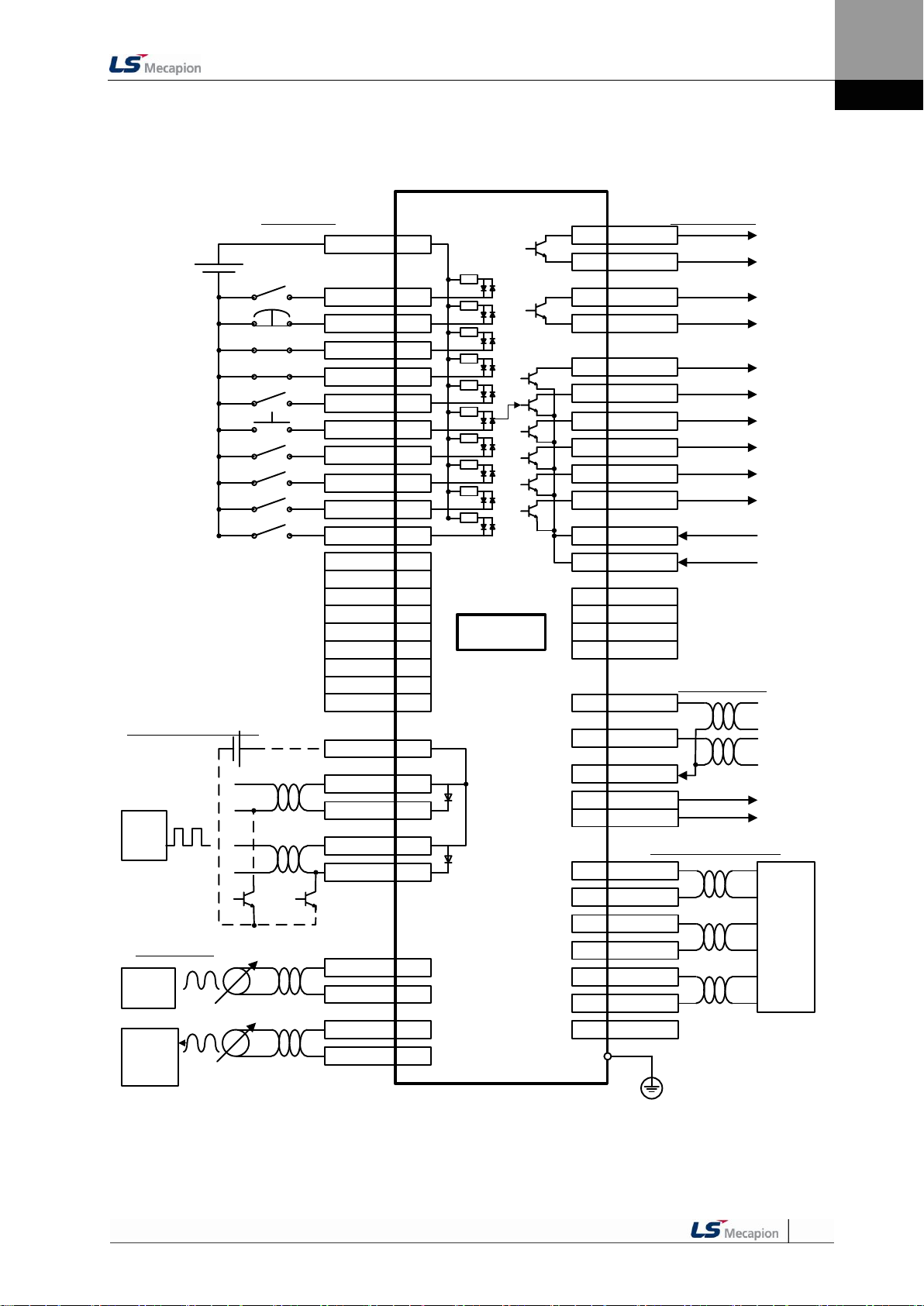
3. Wiring Method
3. Wiring Method
3.1 Internal Block Diagram
3.1.1 L7 Drive Block Diagram [L7SA001□ - L7SA004□]
NOTE 1) If you use a DC reactor, connect to the PO and PI pins.
NOTE 2) If you use external regenerative resistance, connect to the B+ and B pins after removing the B
and BI short-circuit pins.
3-1

3. Wiring Method
3.1.2 L7 Drive Block Diagram [L7SA008□ - L7SA035□]
NOTE 1) If you use a DC reactor, connect to the PO and PI pins.
NOTE 2) If you use external regenerative resistance, connect to the B+ and B pins after you remove the B
and BI short-circuit pins.
NOTE 3) The L7SA008□ and L7SA035□ models are cooled by a DC 24 [V] cooling fan.
3-2

3. Wiring Method
U
V
W
L1
L2
L3
C1
C2
B+
B
BI
38
39
CN1
RA
M
E
Alarm-
Alarm+
1Ry
RA
1SK
1Ry1MC
+24V
NF
1MC
R S T
서보드라이브
(200~230V)
Main
OFF
Main
ON
인코더
외부
회생저항
주1)
주2)
PO
PI
DC 리액터
Servo Drive
Note 1)
DC Reactor
Encoder
Note 2) External
Regenerative Resistancer
7~10 ㎜
3.2 Power Wiring
3.2.1 L7 Drive Wiring Diagram [L7SA001□ - L7SA035□]
3-3
NOTE 1) It takes approximately one to two seconds until alarm signal is output after you turn on the main
NOTE 2) Short-circuit B and BI terminals before use. Regenerative resistance of L7SA001□-L7SA004□
NOTE 3) Remove the sheath of cables to be used for the main circuit power by approximately 7-10 [㎜] and
power. Accordingly, push and hold the main power ON switch for at least two seconds.
(50 [W], 100 [Ω]), L7SA010□ (100 [W], 40 [Ω]), and L7SA035□ (150 [W], 13 [Ω]) exist inside. If
regenerative capacity is high because of frequent acceleration and deceleration, open the shortcircuit pins (B, BI) and connect external regenerative resistance to B and B+.
use devoted crimp terminals. (Refer to “3.2.2 Power Circuit Electric Sub Assembly Standards.”)
NOTE 4) Connect or remove the main circuit power unit wiring after pushing the button of the L7SA001□-
L7SA010□ drive terminal. For drive L7SA035□, use a (-) slot screwdriver for connection and
removal.

3. Wiring Method
Name
L7SA001□
L7SA002□
L7SA004□
L7SA008□
L7SA010□
L7SA020□
L7SA035□
MCCB
ABS33bM (8 A)
12 A
24 A
Noise Filter
(NF)
RFY-4010M
4020M
4030M
DC reactor
HFN-6 (6 A)
HFN-10 (10 A)
HFN-30 (30 A)
MC
GMC-9 (11 A)
GMC-18 (18 A)
GMC-40 (35 A)
Wire
AWG16
(1.25 SQ)
AWG14
(2.0 SQ)
AWG12
(4.0 SQ)
Crimp terminal
UA-F1510, SEOIL
(10 mm Strip & Twist)
UA-F2010, SEOIL
(10 mm Strip & Twist)
UA-F4010, SEOIL
(10 mm Strip & Twist)
Regenerative
resistance
(Provided by
default)
50 [W]
100 Ω
100 [W]
40 Ω
150 [W]
13 Ω
3.2.2 Dimensions for Power Circuit Electrical Parts
3-4

3. Wiring Method
Control power
establishment 5
[V]
Control program
reset
Main power
establishment
Alarm
(Normally On)
Servo Ready
Servo On
Clear DB
PWM output
(motor
rotation)
150 ms
50 ms
120 ms
10 ms
10 ms
5 ms
40 ms
Main power,
control power
supply
200 ms
2 ms
3.3 Timing Diagram
3.3.1 Timing Diagram During Power Input
For L7 Series, connect single-phase power to the C1 and C2 terminals to supply power to
the control circuit, and three-phase power to L1, L2, and L3 to supply power to the main
circuit.
The servo signal becomes Ready after the maximum time of 120 [ms] that is required to
reset the inside of the device. If you change the signal to ON, the servo starts operation in 40
[ms].
3-5

3. Wiring Method
Caution
Never reset the alarm before you solve the problem that triggered the alarm and change the
command signal (Servo ON) to OFF.
200 ms
Control power
establishment
5 [V]
Control
program
Reset
Main power
establishment
Alarm
(Normally On)
Servo RDY
Servo On
Clear DB
PWM
(Motor rotation)
RESET
150 ms
40 ms
10 ms
5 ms
2 ms
30 ms
Alarm triggered by
anomaly
Remove
causes that
triggered
alarm
Main power,
control power
supply
3.3.2 Timing Diagram at the Time of Alarm Trigger
When the alarm triggers in the servo drive, PWM is blocked and the motor stops.
3-6

3. Wiring Method
Caution
1. There are two input contacts based on the characteristics of individual signals: contact A and
contact B. They can be set by [P2-08] and [P2-09].
2. It is possible to turn each contact on or off forcibly with [Cn-07]. Take extra caution, however,
because each contact is automatically turned off when power is off.
3. The signal definition of each contact can be modified by [P2-00], [P2-01], [P2-02], [P2-03], and
[P2-04].
R2
Internal
Circuit
COM
R1
DC 24V
R1: 3.3 KΩ, R2: 680 Ω
3.4 Control Signal Wiring
3.4.1 Contact Input Signal
3-7

3. Wiring Method
Caution
1. There are two output contacts based on the characteristics of individual signals: contact A and
contact B. They can be set by [P2-10].
4. It is possible to turn each contact on or off forcibly with [Cn-08]. Take extra caution, however,
because each contact is automatically turned off when power is off.
5. The signal definition of each contact point can be modified by [P2-05], [P2-06], and [P2-07].
6. Overvoltage and overcurrent may cause damage because a transistor switch is used internally.
Rated voltage and current: DC 24 [V] ±10%, 150 [㎃]
Internal
Circuit
DC 24V
L
L
Contact
Contact
Note 1)
NOTE 1) For alarm and ready output signals, the GND24 terminal is separated.
3.4.2 Contact Output Signal
3-8

3. Wiring Method
Input/output
Servo Drive
Input/output signal
AGND
AGND
Twisted Pair
Shield Wire
FG
330 [Ω] 1/4 [W]
330 [Ω] 1/4 [W]
5 [kΩ]
0.1 [uF]
+12 [V] (34)
-12 [V] (35)
Analog command
(26), (27), (1)
AGND
(8)
3.4.3 Analog Input/Output Signals
1. Keep GND as 0 [V] of control power.
2. Keep the input signal command voltage within ±10 [V], and input impedance at 22 [㏀].
3. Output signal voltage for Monitor 1 (No. 28) and Monitor 2 (No. 29) is ±10 [V].
Configure wiring as shown in the following image when you adjust analog input with
parameter resistance by using power supplied by the drive.
Do not exceed the maximum output capacity of 30 [㎃].
3-9

3. Wiring Method
Servo Drive
Upper level controller
PF
PR
PF+
PF-
PR+
PR-
Line driver
Line receiver
FG
Twisted Pair
Shield Wire
Servo Drive
Upper level controller
+24 [V]
GND24
GND24
Pulse COM
PR-
FG
Shield Wire
PF-
Upper level controller
Servo Drive
PR+
PF+
PF-
PR-
GND12
Power note 1)
NPN
R
R
FG
3.4.4 Pulse Train Input Signal
(1) Line Driver (5 [V]) Pulse Input
(2) Open Collector (24 [V]) Pulse Input
(3) 12 [V] or 5 [V] NPN Open Collector Pulse Command
NOTE 1) When using 5 [V] power: Resistance R = 100-150 [Ω], 1/2 [W]
When using 12 [V] power: Resistance R = 560-680 [Ω], 1/2 [W]
When using 24 [V] power: Resistance R = 1.5 [kΩ], 1/2 [W]
3-10

3. Wiring Method
Servo Drive
Upper level controller
PA
AO
/AO
GND
Line driver
Line receiver
GND
GND
Upper level controller
Servo Drive
Power
note 2)
FG
PNP
PF+
PF-
P
PR+
4
PR-
R
R
(4) PNP Open Collector Pulse Command
NOTE 1) When using 24 [V] power: Resistance R = 1.5 [kΩ], 1/2 [W]
When using 12 [V] power: Resistance R = 560-680 [Ω], 1/2 [W]
When using 5 [V] power: Resistance R = 100-150 [Ω], 1/2 [W]
3.4.5 Encoder Output Signal
Connect the GND terminal of the upper level controller and the GND terminal of CN1
because encoder signals are output based on the GND of control power.
Encoder signals for the servo motor received from CN2 are pre-scaled according to the ratio
defined by [P0-14] / [P0-15] and output in line driver mode.
3-11
Set bit number 2 to 1 in the menu ‘P0-18 Fuction Select Bit',
It outputs open collector A,B,Z phases through existing AL0, AL1 and AL2 contact points.
(Output voltage 40mA and below, Maximum frequency 100Khz)

3. Wiring Method
Encoder
1
2
3
4
5
6
7
8
9
10
11
12
13
14
15
A
/A
B
/B
Z
/Z
U
/U
V
/V
W
/W
5V
GND
SHD
13
12
11
10
9
8
5
6
3
4
1
2
14
7
Frame
Servo Drive
Servo Motor
AWG24 7Pair Twisted
Shield Wire
Cable
Connector
Maker - AMP
172163-1
170361-1
Cable
Connector(CN2)
Maker – 3M
10314-52A0-008
10114-3000VE
Servo Drive
Servo Motor
Encoder
A
B
C
D
E
F
K
L
M
N
P
R
H
G
J
A
/A
B
/B
Z
/Z
U
/U
V
/V
W
/W
5V
GND
SHD
13
12
11
10
9
8
5
6
3
4
1
2
7
Frame
AWG24 7Pair Twisted
Shield Wire
Cable
Connector(CN2)
Maker – 3M
10314-52A0-008
10114-3000VE
Cable
Connector
MS3108B20-29S
14
3.5 Quadrature Encoder Signaling Unit (CN2)
Wiring
3.5.1 APCS-EAS Cable
3.5.2 APCS-EBS Cable
3-12

3. Wiring Method
Encoder
1
2
3
4
7
8
9
MA
SL
/SL
+5V
GND
SHD
3
4
5
6
14
7
Frame
Servo Drive
Servo Motor
AWG24 4Pair Twisted
Shield Wire
Cable
Connector
Maker - AMP
172161-1
170361-1
Cable
Connector(CN2)
Maker – 3M
10314-52A0-008
10114-3000VE
/MA
3.6 Serial Encoder Signaling Unit (CN2)
Wiring
3.6.1 APCS-ECS Cable
3.6.2 APCS-EDS Cable
3-13

3. Wiring Method
Servo Drive
Servo Motor
인코더
1
6
2
7
9
4
5
MA
/MA
SL
/SL
5V
GND
SHD
Cable
Connector(CN2)
Maker - 3M
10314-52A0-008
10114-3000VE
Connector
Tyco Connector
(7Ciruits)
Encoder
3
4
5
6
14
7
Frame
3.6.3 APCS-EES Cable
3-14

3. Wiring Method
Absolute data transmission
Pre-scaler pulse output
3.7 Transmission of Absolute Encoder Data
3.7.1 Transmission of Absolute Encoder Data
Upon the absolute encoder's request for absolute data, the data of the absolute encoder are
transmitted to the upper level controller in the form of quadrature pulses through the output
of the encoder output signals, AO and BO.
In this case, pulses are output at the speed of 500 [Kpps].
Among absolute data, multi-turn data are transmitted first, followed by single-turn data.
(Refer to “4.1.6 External Input Signal and Logic Definition" for information on the allocation of
the sequence input signal and ABS-RQ signal.)
Transmission Sequence of Absolute Data
1. When the servo is off, change the ABS_RQ signal on the upper level controller to ON.
2. The servo drive checks the ABS_RQ signal for 10 [ms].
3. The servo drive prepares the transmission of multi-turn data for 100 [ms].
4. The servo drive transmits multi-turn data for up to 140 [ms] (based on 16-bit multi-turn data).
5. The servo drive prepares the transmission of single-turn data for 100 [ms].
6. The servo drive transmits single-turn data with the pre-scaler ratio applied for up to 1100 [ms]
(based on 19-bit single-turn data).
7. The servo drive operates with normal encoder output signals 100 [ms] after the single-turn data are
completely transmitted.
3-15

4. Parameters
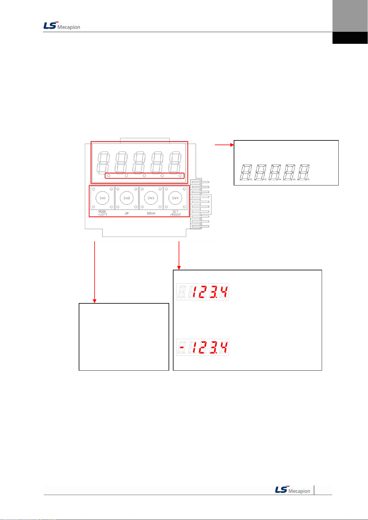
Display 5-digit FND data.
Digit 5 Digit 4 Digit 3 Digit 2 Digit 1
[MODE]: Change display mode.
[/LEFT]: Move to another data digit.
[UP]: Increase displayed data.
[DOWN]: Decrease displayed data.
[SET]: Confirm displayed data.
[/RIGHT]: Move to another data digit.
Displays the decimal point.
E.g.) 123.4
In the case of 16 bits, the minus symbol is used.
In the case of 32 bits, a dot is used.
E.g.) -123.4
4. Parameters
4.1 How to Use the Loader
4.1.1 Name and Function of Each Part
4-1

4. Parameters
DIGIT 3-1: Displays the current status of the servo.
bb - Servo OFF
run - Servo ON
Pot - CCW Limit
not - CW Limit
DIGIT 4_High: ZSPD
DIGIT 4_Medium: INSPD or INPOS
DIGIT 4_Low: Command (speed or torque)
DIGIT 4_DOT: Ready
DIGIT 5: Displays the current control mode.
P - Position control
S - Speed control
T - Torque control
DIGIT 5_DOT: Servo ON
4.1.2 Status Summary Display
(1) Status Summary Display in Speed Mode
① Example of the OFF status of the servo in speed control mode
② Example of the ON status of the servo in speed control mode
4-2

4. Parameters
Operation Status
Screen
Function
Notes
Displays the servo's OFF status when in the
position mode.
Displays the servo's ON status when in position
mode.
Displays CCW status when in position mode.
Displays CW status when in position mode.
Displays the servo's OFF status when in speed
mode.
Displays the servo's ON status when in speed
mode.
Displays CCW status when in speed mode.
Displays CW status when in speed mode.
Displays the servo's OFF status when in torque
mode.
Displays the servo's ON status when in torque
mode.
Displays CCW status when in torque mode.
Displays CW status when in torque mode.
(2) Servo Operation Status Summary Display List
The following list explains the operation status summary display of different modes of the
servo.
4-3

4. Parameters
St-00
St-01
St-02
St-24
St-25
St-26
P0-00
P0-01
P0-02
P0-25
P0-26
P0-27
Cn-00
Cn-01
Cn-02
Cn-13
Cn-14
Cn-15
UP
DOWN
MODE
P4-00
P4-01
P4-02
P4-11
P4-12
P4-13
Operation Status
Summary Display
P1-00 P2-00 P3-00
P1-25 P2-22 P3-20
4.1.3 Parameter Handling
(1) Parameter Movement
Example of changing speed control mode to position control mode ([P0-03]: 00001 -> 00002)
If the alarm does not go off at the start of operation, the speed operation mode [S=bb] indicating
operation status is displayed.
Editable parameters are from [P0-00] to [Cn-15]. Press [SET] when a parameter number is
displayed and you can see and edit the parameter data.
In the initial parameter edit status, the number on the far right flickers (ON and OFF for 0.5 seconds
respectively) and becomes editable.
4-4

4. Parameters
Orde
r
Loader Displays
Keys to Use
What to Do
1
Displays the speed control mode with
main power and control power
permitted.
2
Press [MODE] to move to [P0-00].
3
Press [UP] or [DOWN] to move to [P003].
4
Press [SET] to go to the parameter edit
window. The parameter is displayed as
00001.
5
Press [UP] or [DOWN] at the blinking
cursor to change the number to 00002.
6
Press and hold [SET] for approximately
one second. After two flickers, the
number will be saved as 00002 in the
parameter.
7
Press and hold [MODE] for
approximately one second to return to
the P0-03 parameter.
8
Press [MODE] to change status to
position operation [P= bb] status which
is the summary display of the current
status.
(2) Example of changing speed control mode to position control
mode ( [P0-03]: 00001 -> 00002 )
NOTE 1) “ ” indicates flickering.
NOTE 2) If you hold down [UP] / [DOWN] at the current cursor in the parameter window, the number
continues to increase/decrease.
4-5

4. Parameters
Orde
r
Loader Displays
Keys to Use
What to Do
1
Displays the speed control mode with
main power and control power
permitted.
2
Press [MODE] to move to [P1-00].
3
Press [UP] or [DOWN] to move to [P107].
4
Press [SET] to enter parameter edit
mode. The parameter is displayed as
00200.
5
Press [/LEFT] or [/RIGHT] at the
blinking cursor to move to the desired
digit, DIGIT 3.
6
Press [UP] or [DOWN] at the blinking
DIGIT 3 position to change the number
to 00500.
7
Press and hold [SET] for approximately
one second. After two flickers, the
number will be saved as 00500 in the
parameter.
8
Press and hold [MODE] for
approximately one second to return to
[P1-07].
(3) Example of changing speed proportional gain 2
([P1-07]: 200 [rad/s] -> 500 [rad/s])
NOTE 1) “ ” indicates flickering.
NOTE 2) If you hold down [UP] / [DOWN] at the current cursor in the parameter window, the number
continues to increase/decrease.
4-6

4. Parameters
Orde
r
Loader Displays
Keys to Use
What to Do
1
Displays the speed control mode with
main power and control power
permitted.
2
Press [MODE] to move to [P1-00].
3
Press [UP] or [DOWN] to move to [P020].
4
Press [SET] to enter parameter edit
mode. The parameter is displayed as
00000.
5
Press [/LEFT] or [/RIGHT] at the
blinking cursor to move to the desired
digit, DIGIT 3.
6
Press [UP] or [DOWN] at the blinking
DIGIT 3 position to change the number
to -0500.
7
Press and hold [SET] for approximately
one second. After two flickers, the
number will be saved as -0500 in the
parameter.
8
Press and hold [MODE] for
approximately one second to return to
[P0-20].
(4) Example of changing DAC output offset 1 ([P0-20]: 0 [Unit/V] ->
-500 [Unit/V])
NOTE 1) “ ” indicates flickering.
NOTE 2) If you hold down [UP] / [DOWN] at the current cursor in the parameter window, the number
continues to increase/decrease.
4-7

4. Parameters
① Minimum (0b00000)
② Maximum (0b11111)
① Minimum (0x0000)
② Maximum (0xFFFF)
① E.g.) 0
② E.g.) +1234
① E.g.) -1234
② E.g.) +5678
① E.g.) -123.4
② E.g.) +123.4
4.1.4 Data Display
(1) Binary
(2) Hex
(3) 16-bit Unsigned Integer
(4) 16-bit Signed Integer
① E.g.) -1234 ② E.g.) +5678
(5) 16-bit Decimal Point Display
① E.g.) -123.4 ② E.g.) +123.4
4-8

4. Parameters
Display upper two digits
Display middle four digits
Display lower four digits
Display upper two digits
Display middle four digits
Display lower four digits
Order
Loader Displays
Keys to Use
What to Do
1
Displays the speed control mode with
main power and control power
permitted.
2
Press [MODE] to move to [St-00].
3
Press [UP] or [DOWN] to move to [St16].
4
Press [SET] to display lower digit data.
5
Each time you press [/LEFT] or
[/RIGHT]
lower, middle, and upper data is
displayed.
6
Each time you press [/LEFT] or
[/RIGHT]
lower, middle, and upper data is
displayed.
7
Press and hold [MODE] for
approximately one second to return to
[St-16].
(6) 32-bit Signed Integer Data Display
① Minimum (-2147483648)
② Maximum (2147483647)
E.g.) [St-16]: Displayed as Upper = 0, Middle = 0012, and
Lower = 2071
NOTE 1) “ ” indicates flickering.
4-9

4. Parameters
Number
(A)
(9)
(8)
(7)
(6)
(5)
(4)
(3)
(2)
(1)
Contact
Number
DIA
DI9
DI8
DI7
DI6
DI5
DI4
DI3
DI2
DI1
CN1
Pin number
48
18
19
20
46
17
21
22
23
47
Allocated
default
Signal name
STOP
EMG
CWLIM
CCWLI
M
DIR
ALMR
ST
SPD3
SPD2
SPD1
SVON
4.1.5 External Input Contact Signal Display [St-14]
You can check whether the ON/OFF status of digital input/output signals that access the
servo drive are on or off.
(1) External Input Signal Display
The positions of the seven segment LEDs and CN1 connector pins correspond as follows.
If an LED that corresponds to a pin is turned on/off, it indicates ON/OFF accordingly.
Input Contact Display
4-10

4. Parameters
Input Signal
Input Allocation Number
4.1.6 External Input Signal and Logic Definition
The following describes how to allocate input signals and how to view them.
(1) Input Signal Allocation
L7 Drive allows for the allocation of a total of 19 input contact fuctions to 10 hardware
contacts.
Each of the input contact functions is located at the designated digit of parameter [P2-00],
[P2-01], [P2-02], [P2-03], or [P2-04]. Changing the value of the digit allows allocation to pins
DI1 through DIA
The default input signal allocation is as follows:
One number can be allocated to two input signals such as N (input signal): 1 (input allocation
number).
E.g.) If SVON and SPD1 are allocated to DI #01, you can use both the SVON signal and the
SPD1 signal when entering DI #01.
4-11

4. Parameters
Signal Name
Input
Signal
Alwa
ys
Alloc
ated
CN1 Pin Default Allocation Number
No
Alloc
ation
Input
Signal
Definition
Default
setting
Parameter
Allocation
48
18
19
20
46
17
21
22
23
47
Servo ON
[P2-00].Set Digit 1
SVON
F A 9 8 7 6 5 4 3 2 1
0
[P2-00]
0x4321
Multi-speed 1
[P2-00]. Set Digit 2
SPD1
F A 9 8 7 6 5 4 3 2 1
0
Multi-speed 2
[P2-00]. Set Digit 3
SPD2
F A 9 8 7 6 5 4 3 2 1
0
Multi-speed 3
[P2-00]. Set Digit 4
SPD3
F A 9 8 7 6 5 4 3 2 1
0
Alarm reset
[P2-01]. Set Digit 1
ALMRST
F A 9 8 7 6 5 4 3 2 1
0
[P2-01]
0x8765
Select rotation
direction
[P2-01]. Set Digit 2
DIR
F A 9 8 7 6 5 4 3 2 1
0
Forward rotation
prohibited
[P2-01]. Set Digit 3
CCWLIM
F A 9 8 7 6 5 4 3 2 1
0
Reverse rotation
prohibited
[P2-01]. Set Digit 4
CWLIM
F A 9 8 7 6 5 4 3 2 1 0 Emergency stop
[P2-02]. Set Digit 1
EMG
F A 9 8 7 6 5 4 3 2 1
0
[P2-02]
0x00A9
Stop
[P2-02]. Set Digit 2
STOP
F A 9 8 7 6 5 4 3 2 1
0
Electronic gear
ratio 1
[P2-02]. Set Digit 3
EGEAR1
F A 9 8 7 6 5 4 3 2 1
0
Electronic gear
ratio 2
[P2-02]. Set Digit 4
EGEAR2
F A 9 8 7 6 5 4 3 2 1 0 P control action
[P2-03]. Set Digit 1
PCON
F A 9 8 7 6 5 4 3 2 1
0
[P2-03]
0x0000
Select gain 2
[P2-03]. Set Digit 2
GAIN2
F A 9 8 7 6 5 4 3 2 1
0
Input pulse clear
[P2-03]. Set Digit 3
P_CLR
F A 9 8 7 6 5 4 3 2 1
0
Torque limit
[P2-03]. Set Digit 4
T_LMT
F A 9 8 7 6 5 4 3 2 1
0
Change operation
modes
[P2-04]. Set Digit 1
MODE
F A 9 8 7 6 5 4 3 2 1
0
[P2-04]
0x0000
Absolute encoder
data request
[P2-04]. Set Digit 2
ABS_RQ
F A 9 8 7 6 5 4 3 2 1 0 Zero clamp
[P2-04]. Set Digit 3
ZCLAMP
F A 9 8 7 6 5 4 3 2 1
0
4-12
NOTE 1) No CN1 connector pin is allocated when the default value is "0".

4. Parameters
Input Signal
Input Allocation Number
(2) Example of Changing Input Signal Allocation
The input signal definition can be changed in [P2-00], [P2-01], [P2-02], [P2-03], and [P2-04].
The input signal logic definition can be changed in [P2-08] and [P2-09].
Allocate input signals as shown in the following table:
4-13

4. Parameters
Signal Name
Input
Signal
Alwa
ys
Alloc
ated
CN1 Pin Default Allocation Number
No
Alloc
ation
Input
Signal
Definition
Value
After
Changing
Parameter
Allocation
48
18
19
20
46
17
21
22
23
47
Servo ON
[P2-00].Set Digit 1
SVON
F A 9 8 7 6 5 4 3 2 1
0
[P2-00]
0x0321
Multi-speed 1
[P2-00]. Set Digit 2
SPD1
F A 9 8 7 6 5 4 3 2 1
0
Multi-speed 2
[P2-00]. Set Digit 3
SPD2
F A 9 8 7 6 5 4 3 2 1
0
Multi-speed 3
[P2-00]. Set Digit 4
SPD3
F A 9 8 7 6 5 4 3 2 1
0
Alarm reset
[P2-01]. Set Digit 1
ALMRST
F A 9 8 7 6 5 4 3 2 1
0
[P2-01]
0x0765
Select rotation
direction
[P2-01]. Set Digit 2
DIR
F A 9 8 7 6 5 4 3 2 1
0
Forward rotation
prohibited
[P2-01]. Set Digit 3
CCWLIM
F A 9 8 7 6 5 4 3 2 1
0
Reverse rotation
prohibited
[P2-01]. Set Digit 4
CWLIM
F A 9 8 7 6 5 4 3 2 1 0 Emergency stop
[P2-02]. Set Digit 1
EMG
F A 9 8 7 6 5 4 3 2 1
0
[P2-02]
0x0080
Stop
[P2-02]. Set Digit 2
STOP
F A 9 8 7 6 5 4 3 2 1
0
Electronic gear
ratio 1
[P2-02]. Set Digit 3
EGEAR1
F A 9 8 7 6 5 4 3 2 1
0
Electronic gear
ratio 2
[P2-02]. Set Digit 4
EGEAR2
F A 9 8 7 6 5 4 3 2 1 0 P control action
[P2-03]. Set Digit 1
PCON
F A 9 8 7 6 5 4 3 2 1
0
[P2-03]
0x9000
Select gain 2
[P2-03]. Set Digit 2
GAIN2
F A 9 8 7 6 5 4 3 2 1
0
Input pulse clear
[P2-03]. Set Digit 3
P_CLR
F A 9 8 7 6 5 4 3 2 1
0
Torque limit
[P2-03]. Set Digit 4
T_LMT
F A 9 8 7 6 5 4 3 2 1
0
Change operation
modes
[P2-04]. Set Digit 1
MODE
F A 9 8 7 6 5 4 3 2 1
0
[P2-04]
0x000A
Absolute encoder
data request
[P2-04]. Set Digit 2
ABS_RQ
F A 9 8 7 6 5 4 3 2 1 0 Zero clamp
[P2-04]. Set Digit 3
ZCLAMP
F A 9 8 7 6 5 4 3 2 1
0
4-14
NOTE 1) No CN1 connector pin is allocated when the default value is "0".

4. Parameters
Before Changing
After Changing
[P2-00]:
[P2-02]:
Order
Loader Displays
Keys to Use
What to Do
1
Press [MODE] to move to [P2-00].
2
Press [SET] to enter parameter edit
mode. The parameter is displayed as
04321.
3
Press [UP] or [DOWN] at the blinking
cursor to change the number to
0432A.
4
Hold down [SET] for approximately
one second. After two flickers, the
number is saved as 0432A for the
parameter.
5
Hold down [MODE] for approximately
one second to return to [P2-00].
6
Press [UP] or [DOWN] at the blinking
cursor to change the number to P2-02.
7
Press [SET] to enter parameter edit
mode. The parameter is displayed as
000A9.
8
Press [/LEFT] or [/RIGHT] at the
blinking cursor to move to the desired
digit, DIGIT 2.
9
Press [UP] or [DOWN] at the blinking
cursor to change the number to
00019.
10
Hold down [SET] for approximately
one second. After two flickers, the
number is saved as 00019 for the
parameter.
11
Hold down [MODE] for approximately
one second to return to [P2-02].
12
** Modification is not possible with the servo on &. Reset the parameter.
※
In case of exiting
without saving the set
value
Hold down [MODE] for approximately
one second to return to the parameter.
Examples of Changing Input Signal Allocation
The following is an example of changing input signal allocation.
The allocation signals of SVON (CN1-47) and STOP (CN1-48) can be switched in the
following sequence.
NOTE 1) “ ” indicates flickering.
4-15

4. Parameters
Signal Name
Input
Signal
(Initial
name)
CN1 Pin Default Allocation Number
Contact B
Input
signal
logic
setting
Default
setting
Parameter
Allocation
48
18
19
20
46
17
21
22
23
47
Servo ON
[P2-08].Set Digit 1
SVON
1 0
[P2-08]
0x11111
Multi-speed 1
[P2-08]. Set Digit 2
SPD1
1 0
Multi-speed 2
[P2-08]. Set Digit 3
SPD2
1 0
Multi-speed 3
[P2-08]. Set Digit 4
SPD3
1 0
Alarm reset
[P2-08]. Set Digit 5
ALMRST
1 0
[P2-09]
0x10001
Select rotation
direction
[P2-01]. Set Digit 2
DIR 1
0
Forward rotation
prohibited
[P2-01]. Set Digit 3
CCWLIM
0
Reverse rotation
prohibited
[P2-01]. Set Digit 4
CWLIM
0
Emergency stop
[P2-02]. Set Digit 1
EMG
0
Stop
[P2-02]. Set Digit 2
STOP
1 0
Input signal logic definition
Input signal logic definition number
(3) Input signal logic definition
L7 Drive allows for defining the logic of input signals for 10 hardware contacts from DI1 to
DIA through parameters [P2-08] and [P2-09].
The logic of input signals as set in the factory is as follows.
4-16
NOTE 1) For the purpose of the input signal logic definitions, Contact A is 1 and Contact B is 0.

4. Parameters
Signal Name
Input
Signal
CN1 Pin Default Allocation Number
Cont
act B
Input
signal
logic
definition
Default
setting
Parameter
Allocation
48
18
19
20
46
17
21
22
23
47
Servo ON
[P2-08].Set Digit 1
SVON
1 0
[P2-08]
0x11111
Multi-speed 1
[P2-08]. Set Digit 2
SPD1
1 0
Multi-speed 2
[P2-08]. Set Digit 3
SPD2
1 0
Multi-speed 3
[P2-08]. Set Digit 4
SPD3
1 0
Alarm reset
[P2-08]. Set Digit 5
ALMRST
1 0
Select rotation
direction
[P2-01]. Set Digit 2
DIR 1
0
[P2-09]
0x11101
Forward rotation
prohibited
[P2-01]. Set Digit 3
CCWLIM
0
Reverse rotation
prohibited
[P2-01]. Set Digit 4
CWLIM
1 0
Emergency stop
[P2-02]. Set Digit 1
EMG
1 0
Stop
[P2-02]. Set Digit 2
STOP
1 0
Input signal logic definition
Input signal logic definition number
(4) Example of Changing Input Signal Logic Definitions
Input signal logic definitions can be changed in [P2-08] and [P2-09].
When input signals are allocated as below, settings will be done as shown in table below.
NOTE 1) For the purpose of the input signal logic definition, Contact A is 1 and Contact B is 0.
4-17

4. Parameters
Before changing
After changing
[P2-08]:
[P2-09]:
Order
Loader Displays
Keys to Use
What to Do
1
Press [UP] or [DOWN] at the blinking
cursor to move to [P2-08].
2
Press [SET] to enter parameter edit
mode. The parameter is displayed as
11111.
3
Press [UP] or [DOWN] at the blinking
cursor to change the number to 11110.
4
Hold down [SET] for approximately
one second. After two flickers, the
number is saved as 11110 for the
parameter.
5
Hold down [MODE] for approximately
one second to return to [P2-08].
6
Press [UP] or [DOWN] at the blinking
cursor to change the number to [P209].
7
Press [SET] to enter parameter edit
mode. The parameter is displayed as
10001.
8
Press [/LEFT] or [/RIGHT] at the
blinking cursor to move to the desired
digit, DIGIT 2.
9
Press [UP] or [DOWN] at the blinking
cursor to change the number to 10011.
10
Hold down [SET] for approximately
one second. After two flickers, the
number is saved as 10011 for the
parameter.
11
Hold down [MODE] for approximately
one second to return to [P2-09].
12
** Modification is not possible with the servo on &. Reset the parameter.
※
In case of exiting
without saving the set
value
Hold down [MODE] for approximately
one second to return to the parameter.
Examples of changing input signal logic definitions
The table below shows examples of changing input signal logic definitions.
The sequence of changing logic signal contact A of SVON (CN1-47) to contact B and logic
signal contact B of CCWLIM (1-20) to contact A is as follows.
NOTE 1) “ ” indicates flickering.
4-18

4. Parameters
Number
(5)
(4)
(3)
(2)
(1)
Contact
Number
DO5
DO4
DO3
DO2
DO1
CN1
pin number
45
44
43
40/41
38/39
Allocated default
signal name
INPOS
BRAKE
ZSPD
READY
ALARM
4.1.7 External Output Contact Signal Display [St-15]
You can check whether the ON/OFF status of digital input/output signals that access the
servo drive are on or off.
(1) External Output Signal Display
The positions of the seven segment LEDs and CN1 connector pins correspond as follows.
If an LED that corresponds to a pin is turned on/off, it indicates ON/OFF accordingly.
Output Contact Display
4-19
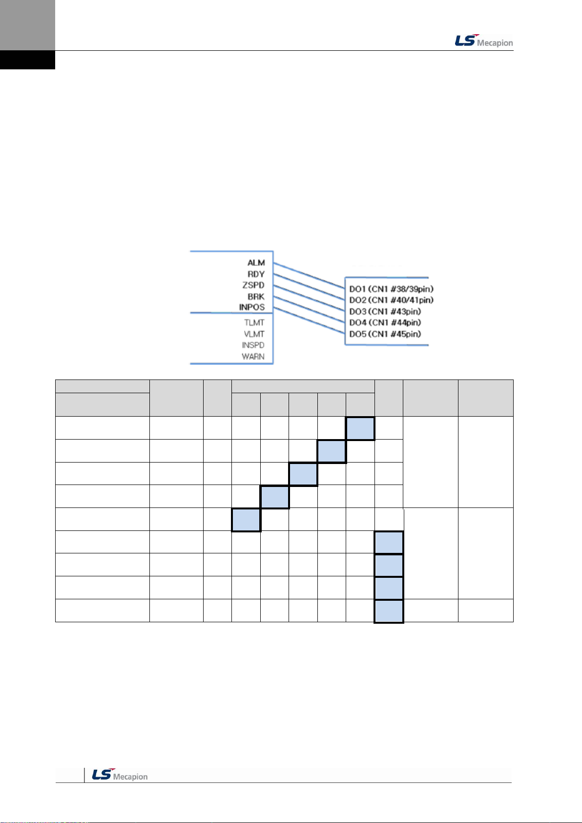
4. Parameters
Signal Name
Output
Signal
Alwa
ys
Alloc
ated
CN1 Pin Default Allocation Number
Not
Alloc
ated
Internal
Parameter
Default
Value
Parameter Allocation
45
44
43
40/41
38/39
Alarm
[P2-05].Set Digit 1
ALARM
F 5 4 3 2 1 0
[P2-05]
0x4321
Servo Ready
[P2-05]. Set Digit 2
READY
F 5 4 3 2 1 0
Zero speed achieved
[P2-05]. Set Digit 3
ZSPD
F 5 4 3 2 1 0
Brake
[P2-05]. Set Digit 4
BRAKE
F 5 4 3 2 1 0
Position reached
[P2-06]. Set Digit 1
INPOS
F 5 4 3 2 1 0
[P2-06]
0x0005
Torque limit reached
[P2-06]. Set Digit 2
TLMT
F 5 4 3 2 1 0
Speed limit reached
[P2-06]. Set Digit 3
VLMT
F 5 4 3 2 1 0
Speed achieved
[P2-06]. Set Digit 4
INSPD
F 5 4 3 2 1 0
Warning
[P2-07]. Set Digit 1
WARN
F 5 4 3 2 1 0
[P2-07]
0x0000
Output Signal
Output Allocation Number
4.1.8 External Output Signal and Logic Definition
The following explains output signal allocation and the method of checking allocation status.
(1) Output Signal Allocation
Output signal definition: [P2-05], [P2-06], [P2-07]
Output signal logic definition: [P2-10]
The default output signal allocation is as follows:
NOTE 1) No CN1 connector pin is allocated when the default value is "0".
4-20

4. Parameters
Signal Name
Output
Signal
Alwa
ys
Alloc
ated
CN1 Pin Default Allocation Number
Not
Alloc
ated
Internal
Parameter
Value
After
Changing
Parameter Allocation
45
44
43
40/41
38/39
Alarm
[P2-05].Set Digit 1
ALARM
F 5 4 3 2 1 0
[P2-05]
0x0301
Servo Ready
[P2-05]. Set Digit 2
READY
F 5 4 3 2 1 0
Zero speed achieved
[P2-05]. Set Digit 3
ZSPD
F 5 4 3 2 1 0
Brake
[P2-05]. Set Digit 4
BRAKE
F 5 4 3 2 1 0
Position reached
[P2-06]. Set Digit 1
INPOS
F 5 4 3 2 1 0
[P2-06]
0x5400
Torque limit reached
[P2-06]. Set Digit 2
TLMT
F 5 4 3 2 1 0
Speed limit reached
[P2-06]. Set Digit 3
VLMT
F 5 4 3 2 1 0
Speed achieved
[P2-06]. Set Digit 4
INSPD
F 5 4 3 2 1 0
Warning
[P2-07]. Set Digit 1
WARN
F 5 4 3 2 1 0
[P2-07]
0x0002
Output Signal
Output Allocation Number
(2) Examples of Changing Output Signal Allocation
The output signal definition can be changed in [P2-05], [P2-06], and [P2-07].
The output signal logic definition can be changed in [P2-10].
Allocate output signals as in the following table:
4-21
NOTE 1) No CN1 connector pin is allocated when the default value is "0".

4. Parameters
Before Changing
After Changing
[P2-05]:
Order
Loader Window Display
Result
Keys to Use
What to Do
1
Press [MODE] to move to [P2-05].
2
Press [SET] to enter parameter
edit mode. The parameter is
displayed as 04321.
3
Press [UP] or [DOWN] at the
blinking cursor to change the
number to 04323.
4
Press [/LEFT] or [/RIGHT] at the
blinking cursor to move to the
desired digit, DIGIT 3.
5
Press [UP] or [DOWN] at the
blinking cursor to change the
number to 04123.
6
Hold down [SET] for approximately
one second. After two flickers, the
number will be saved as 04123 for
the parameter.
7
Hold down [MODE] for
approximately one second to
return to [P2-05].
8
** Modification is not possible with the servo on & Reset the parameter.
※
In case of exiting without
saving the set value
Hold down [MODE] for
approximately one second to
return to the parameter.
Example of Changing Output Signal Allocation
The following is an example of output signal allocation change.
The sequence of switching the allocation signals of ALARM (CN1-38/39) and ZSPD (CN1-
43) is as follows:
NOTE 1) “ ” indicates flickering.
If two output signals are allocated to a number, the output contact setting error [AL-72] alarm
will be triggered.
4-22

4. Parameters
Signal Name
Input
Signal
(Initial
Name)
CN1 Pin Default Allocation Number
Contact B
Output
Signal
Logic
Definition
Default
Setting
Parameter Allocation
45
44
43
40 /41
38 /39
Alarm
[P2-10].Set Digit 1
ALARM
0
[P2-10]
0x10110
Servo Ready
[P2-10]. Set Digit 2
READY
1
0
Zero speed achieved
[P2-10].Digit 3
ZSPD
1
0
Brake
[P2-10].Digit 4
BRAKE
0
Position reached
[P2-10].Digit 5
INPOS
1
0
Output signal logic definition number
Output signal logic definitions
DO1(Contact A/Contact B)
DO2(Contact A/Contact B)
DO3(Contact A/Contact B)
DO4(Contact A/Contact B)
DO5(Contact A/Contact B)
(3) Output Signal Logic Definition
Output signal logic definition: [P2-10]
The logic of output signals as shipped from the factory is as follows.
NOTE 1) For the purpose of the input signal logic definition, Contact A is 1 and Contact B is 0
4-23

4. Parameters
Signal Name
Input
Signal
(Initial
Name)
CN1 Pin Default Allocation Number
Contact B
Output
Signal
Logic
Definition
Default
Setting
Parameter Allocation
45
44
43
40 /41
38 /39
Alarm
[P2-10].Set Digit 1
ALARM
0
[P2-10]
0x11110
Servo Ready
[P2-10]. Set Digit 2
READY
1
0
Zero speed achieved
[P2-10].Digit 3
ZSPD
1
0
Brake
[P2-10].Digit 4
BRAKE
1
0
Position reached
[P2-10].Digit 5
INPOS
1
0
Output signal logic definitions
Output signal logic definition number
DO1(Contact A/Contact B)
DO2(Contact A/Contact B)
DO3(Contact A/Contact B)
DO4(Contact A/Contact B)
DO5(Contact A/Contact B)
(4) Examples of Changing Output Singal Logic Definition
Output signal logic definitions can be changed at [P2-10]
Set output singals as shown in the table below when they are allocated as below.
For the purpose of the input signal logic definition, Contact A is 1 and Contact B is 0
4-24

4. Parameters
Before Changing
After Changing
[P2-05]:
Order
Loader Window Display
Result
Keys to Use
What to Do
1
Press [MODE] to move to [P2-05].
2
Press [SET] to enter parameter
edit mode. The parameter is
displayed as 04321.
3
Press [UP] or [DOWN] at the
blinking cursor to change the
number to 04323.
4
Press [/LEFT] or [/RIGHT] at the
blinking cursor to move to the
desired digit, DIGIT 3.
5
Press [UP] or [DOWN] at the
blinking cursor to change the
number to 04123.
6
Hold down [SET] for approximately
one second. After two flickers, the
number will be saved as 04123 for
the parameter.
7
Hold down [MODE] for
approximately one second to
return to [P2-05].
8
** Modification is not possible with the servo on & Reset the parameter.
※
In case of exiting without
saving the set value
Hold down [MODE] for
approximately one second to
return to the parameter.
Example of Changing Output Signal Allocation
The following is an example of output signal allocation change.
The sequence of switching the allocation signals of ALM (CN1-38/39) and ZSPD (CN1-43) is
as follows:
NOTE 1) “ “ indicates flickering.
If two output signals are allocated to a number, the output contact setting error [AL-72] alarm
will be triggered.
4-25

4. Parameters
Move to
Another
Parameter
Parameter
Number
Initial Screen
Parameter
Group Name
Details
MODE Key
-
E.g.) In speed mode
Status Summary
Display
Displays the status
summary of the servo.
St-00 - St-26
Status
Displays the operation
status of the servo.
P0-00 - P0-27
System
Saves system
configuration
information.
P1-00 - P1-29
Control
Save control-related
parameters.
P2-00 - P2-22
IN / OUT
Saves parameters
related to analog and
digital input/output.
P3-00 - P3-20
Speed
Operation
Saves speed
operation parameters.
P4-00 - P4-14
Position
Operation
Saves position pulse
operation parameters.
Cn-00 - Cn-18
Command
Performs operation
handling.
4.2 Parameter Description
4.2.1 Parameter System
There are a total of eight groups of parameters. Each group is explained in the following
table:
4-26
The following explains the acronyms related to application mode in the parameter.
P: Use in position control mode.
S: Use in speed control mode.
T: Use in torque control mode.
Press [MODE] once to move to the next display mode.

4. Parameters
Parameter
Unit
Initial
Details
Code
Name
Minimum
Maximum
St-00
Current operation status
-
-
Displays the current operation status.
DIGIT 5: Operation Mode
DIGIT 4: ZSPD, INPOS/INSPD, Command, READY
DIGIT 3-1: Run Status
(Details: Refer to "4.1.2 Status Summary Display.")
Operation status
0
0
St-01
Current operation speed
[RPM]
0
Displays the current operation speed.
(Details: Refer to “4.3.2 Speed Display.”)
Current speed
-10000
10000
St-02
Current command speed
[RPM]
0
Displays the current command speed.
(Details: Refer to “4.3.2 Speed Display.”)
Command speed
-10000
10000
St-03
Follow position pulse
[pulse]
0
Displays the accumulated number of tracked position
command pulses.
Displays the accumulated number of position
command pulses that followed as a result of the
rotation of the servo motor because the servo was
turned on.
If a number is lower than the minimum or higher
than the maximum, it is displayed as the minimum
or maximum.
(Details: Refer to “4.3.3 Position Display.”)
Feedback pulse
-2^30
2^30
St-04
Position command pulse
[pulse]
0
Displays the accumulated number of position
command pulses.
Displays the accumulated number of position
command pulses that have been entered since the
servo turned on.
(Details: Refer to “4.3.3 Position Display.”)
Command pulse
-2^30
2^30
St-05
Remaining position pulse
[pulse]
0
Displays the remaining position pulses that the servo
has to operate.
This is the difference between command pulse and
tracking pulse, and displays the remaining position
pulses for the servo to operate.
The remaining position pulses, which are displayed
when the servo is off, are ignored when the servo
turns on.
(Details: Refer to “4.3.3 Position Display.”)
Pulse error
-2^30
2^30
St-06
Input pulse frequency
[Kpps]
0.0
Displays input pulse frequency.
Input Pulse frequency
-1000.0
1000.0
St-07
Current operation torque
[%]
0.0
Displays the current load factor against the rated load
factor.
Displays the load currently output by the servo
motor as a percentage against the rated output.
Current torque
-300.0
300.0
St-08
Current command torque
[%]
0.0
Displays the command load factor against the rated
load factor.
Displays the load currently output by the servo
motor as a percentage against the rated output.
(Details: Refer to “4.3.4 Torque and Load Display.”)
Command torque
-300.0
300.0
4.2.2 Operation Status Display Parameter
For detailed information, refer to "4.3 Operation Status Display."
“**” Modification is not possible with the servo on & Power reset parameter.
“*” Parameter that cannot be modified with the servo on
4-27

4. Parameters
Parameter
Unit
Initial
Details
Code
Name
Minimum
Maximum
St-09
Accumulated overload
rate
[%]
0.0
Displays the currently accumulated load factor against
the maximum accumulated load factor as a
percentage.
(Details: Refer to “4.3.4 Torque and Load Display.”)
Accumulated overload
-300.0
300.0
St-10
Instantaneous maximum
load factor
[%]
0.0
Displays the instantaneous maximum load factor
against the rated load factor.
Displays, as a percentage, the maximum overload
between the current time and the start of control set
off when the servo turned on.
(Details: Refer to “4.3.4 Torque and Load Display.”)
Maximum load
-300.0
300.0
St-11
Torque limit
[%]
-
Displays the torque limit value.
Displays, as a percentage, the maximum torque
that the servo motor can output, against the rated
torque.
(T_LMT contact ON: Analog torque input. T_LMT
contact OFF: [P1-13] and [P1-14] values)
Torque limit
-300.0
300.0
St-12
DC link voltage
[V]
0.0
Displays the current DC link voltage of the main power.
The DC link voltage of the standard drive that uses
220 [V] is approximately 300 [V].
The maximum DC link voltage allowed for the
standard drive that uses 220 [V] is 405 [V].
The overvoltage alarm [AL-41] triggers when the
DC link voltage threshold is exceeded because
there is either too much or too little regenerative
resistance.
The normal DC link voltage in the regenerative
section is 385 [V] or below.
(Details: Refer to “4.3.4 Torque and Load Display.”)
DC link voltage
0.0
500.0
St-13
Regenerative overload
[%]
0.0
Displays the regenerative overload rate.
Regeneration overload
0.0
20.0
St-14
Input contact status
-
-
Displays the input contact status that the servo
recognizes.
(Details: Refer to “4.1.5 External Input Contact Signal
Display.”)
Input Status
-
-
St-15
Output contact status
-
-
Displays the output contact status that the servo
outputs.
(Details: Refer to “4.1.6 External Input Contact Signal
Display.”)
Output status
-
-
St-16
Single-turn data
(Single-turn data)
[pulse]
0
Displays the single-turn data of the encoder in pulses.
Single-turn data
0
2^30
St-17
Single-turn data
(Degrees)
[˚]
0.0
Displays the single-turn data of the encoder in degrees.
Single-turn data
(Degrees)
0.0
360.0
St-18
Multi-turn data
[rev]
0
Displays the multi-turn data of the encoder.
Multi-turn data
-32768
32767
4-28

4. Parameters
Parameter
Unit
Initial
Details
Code
Name
Minimum
Maximum
St-19
Internal temperature
[℃]
0
Displays the internal temperature sensor value.
Room temperature
0
200
St-20
Rated motor speed
[RPM]
0
Displays the rated speed of the currently
installed motor.
Rated RPM
0
10000
St-21
Maximum motor speed
[RPM]
0
Displays the maximum speed of the currently
installed motor.
Maximum RPM
0
10000
St-22
Rated motor current
[A]
0.00
Displays the rated current of the currently
installed motor.
Rated current
0.00
655.35
St-23
U phase current offset
[mA]
0
Displays the U phase current offset.
U Phase current
offset
-200
200
St-24
V phase current offset
[mA]
0
Displays the V phase current offset.
V phase current
offset
-200
200
St-25
Program version
-
-
Displays the version of the currently installed
program.
(Details: Refer to “4.3.7 Software Version
Display.”)
Software version
-
-
St-26
FPGA 버전
-
-
Displays the version of the currently installed
FPGA version.
FPGA Version
-
-
4-29

4. Parameters
Parameter
Unit
Initial
Details
Code
Name
Minimum
Maximum
**P0-00
Motor ID
-
999
Serial type encoder: Reads the motor ID from the
encoder and displays it.
Quadrature Type encoder: Sets motor ID directly.
If the attempt to read motor data fails, the initial
value is set to 999.
(Details: Refer to “4.4.1 System Parameter
Setting.")
Motor ID
0
999
**P0-01
Encoder type
-
0
Serial Type encoder: Reads and displays from the
encoder.
Quadrature Type encoder: Sets the value directly.
0: Quadrature Type encoder
1: Serial encoder (-)
2: Serial encoder (12 bit)
3: Serial encoder (16 bit)
4: Serial encoder (20 bit)
5: Serial encoder (24 bit)
(Details: Refer to “4.4.1 System Parameter
Setting.")
Encoder type
0
5
**P0-02
Encoder pulse
[ppr]
3000
Serial Type encoder: Reads the number of bits
per turn from the encoder and displays it.
Quadrature Type encoder: Sets the number of
encoder pulses directly.
(Details: Refer to “4.4.1 System Parameter
Setting.")
Enc resolution
1
30000
*P0-03
Select operation
mode
-
1
Sets operation mode.
(0: Torque operation. 1: Speed operation. 2: Position
operation. 3: Speed/position operation. 4:
Torque/speed operation. 5: Torque/position
operation.)
(Details: Refer to “4.4.1 Speed Operation Parameter
Setting.")
Operation mode
0
5
**P0-04
RS422
communication
speed
[bps]
0
Sets communication speed for RS-422
communication.
0 : 9600 [bps]
1 : 19200 [bps]
2 : 38400 [bps]
3 : 57600 [bps]
(Details: Refer to “4.4.1 System Parameter Setting.")
RS422 baud rate
0
3
**P0-05
System ID
-
0
Sets drive ID for communication.
An ID can be given to the servo if USB
communication, RS422 communication and BUS
communication are used for communication with
the servo.
A unique ID can be given to the servo and used
for individual communication with it.
(Details: Refer to “4.4.1 System Parameter Setting.")
System ID
0
99
4.2.3 System Setting Parameter
For detailed information, refer to "4.4.1 System Parameter Setting."
“**” Modification is not possible with the servo on & Power reset parameter.
“*” Parameter that cannot be modified with the servo on
4-30

4. Parameters
Parameter
Unit
Initial
Details
Code
Name
Minimum
Maximum
P0-06
Main power input mode
-
0b00
Sets main power input.
DIGIT 1-> 0: Single-phase power
1: 3-phase power input
Caution: Using single-phase power
may lower motor output.
DIGIT2 -> 0: Error in case of phase loss
1: Warning in case of phase loss
Power fail mode
0b00
0b11
P0-07
RST checking time
[ms]
20
Sets the time to check main power phase
loss.
RST check time
0
5000
P0-08
Displays parameter
upon start.
-
0
Sets the number for the operation status
parameter that is displayed at the start.
(Details: Refer to “4.4.1 System Parameter
Setting.")
Start up parameter
0
25
*P0-09
Regenerative overload
derating
[%]
100
Sets derating factor for checking of
regenerative resistance overload. The
overload alarm triggers quickly when the
derating value is set to 100% or below.
Regeneration derating
1
200
**P0-10
Regenerative resistance
value
[Ω]
0
Sets the resistance value for regenerative
braking resistance. If set to 0, the default
resistance value of the drive is used.
Regenerarion
brake resistor
0
1000
**P0-11
Regenerative resistance
capacity
[W]
0
Sets the capacity for the current
regenerative resistance. If set to 0, a default
resistance capacity embedded in the drive
is used.
Regenerarion brake
capacity
0
30000
*P0-12
Overload check
Base load factor
[%]
100
Indicates the load factor for starting
continuous overload checks. If set to 100 or
below, an overload check starts early and
the overload alarm triggers early.
Overload check base
10
100
P0-13
Continuous overload
warning level
[%]
50
Indicates the level of continuous overload
warning signal output. Outputs the warning
signal when the percentage value against
alarm trigger load factor is reached.
Overload Warning Level
10
100
*P0-14
Encoder output prescale
numerator
-
1
Sets the prescale numerator for encoder
output when the servo outputs an encoder
signal to the outside.
(Details: Refer to “4.4.1 System Parameter
Setting.")
Encoder out NUM.
1
16383
*P0-15
Encoder output prescale
denominator
-
1
Sets the prescale denominator for encoder
output when the servo outputs an encoder
signal to the outside.
(Details: Refer to “4.4.1 System Parameter
Setting.")
Encoder out DEN.
1
16383
*P0-16
PWM OFF delay time
[ms]
10
Sets the time to delay until the PWM signal
actually goes off after the servo is turned off.
(Details: Refer to “4.4.1 System Parameter
Setting.")
PWM OFF delay
0
1000
4-31

4. Parameters
Parameter
Unit
Initial
Details
Code
Name
Minimum
Maximum
*P0-17
DB control mode
-
0x0
Sets DB control mode.
0: Hold after DB stop
1: Release after DB stop
2: Release after free run stop
3: Hold after free run stop
(Details: Refer to “4.4.1 System Parameter
Setting.")
DB control mode
0x0
0x3
*P0-18
Function setting bit
-
0b00
Sets drive function per digit.
DIGIT 1 -> Sets the operation direction of the
servo.
0: Foward (CCW), Reverse (CW)
1: Forward (CW), Reverse (CCW)
DIGIT 2 -> Sets the open collector output.
0: Not for use
1: Use
DIGIT 4 -> Sets the monitor output.voltage
0: -10V~+10V 1: 0~10V
(Details: Refer to “4.4.1 System Parameter
Setting.")
Function select bit
0b00
0b11
P0-19
DAC output mode
-
0x3210
Sets output mode for 1-4 analog output
channels.
Sets CH0-CH3 from the bottom, HEX Code, in
order.
Output CH0 and CH1 as MONIT1 and
MONIT2.
0 : Speed Feedback [RPM]
1 : Speed Command [RPM]
2 : Torque Feedback [%]
3 : Torque Command [%]
4 : Position Command Frequency [0.1
Kpps]
5 : Following Error [pulse]
6 : DC Link Voltage [V]
D: Speed command (User) [RPM]
E: Torque command (User) [%]
(Details: Refer to “4.4.1 System Parameter
Setting.")
DAC mode (F)
0x0000
0xFFFF
P0-20
DAC output offset 1
(MONIT1)
[Unit/V]
0
Sets offset for 1-4 analog output channels.
Speed: [RPM]
Torque: [%]
Position command frequency: [0.1 Kpps]
Position: [pulse]
DC Link: [V]
Offset
(Details: Refer to “4.4.1 System Parameter
Setting.")
DAC output offset 1
(MONIT1)
-1000
1000
P0-21
DAC output offset 2
(MONIT2)
[Unit/V]
0
DAC offset 2 (F)
(MONIT2)
-1000
1000
P0-22
DAC Output Offset 3
[Unit/V]
0
DAC offset 3 (F)
-1000
1000
P0-23
DAC Output Offset 4
[Unit/V]
0
DAC offset 4 (F)
-1000
1000
4-32

4. Parameters
Parameter
Unit
Initial
Details
Code
Name
Minimum
Maximum
P0-24
DAC output scale 1
(MONIT1)
[Unit/V]
500
Sets magnification for 1-4 analog output
channels.
Sets magnification as setting Unit/V.
E.g.) Channel 1 scale 100 [RPM]: Output 100
[RPM] as 1 [V].
(Details: Refer to “4.4.1 System Parameter
Setting.")
DAC scale1 (F)
(MONIT1)
1
10000
P0-25
DAC output scale 2
(MONIT2)
[Unit/V]
500
DAC scale 2 (F)
(MONIT2)
1
10000
P0-26
DAC output scale 3
[Unit/V]
50
DAC scale 3 (F)
1
10000
P0-27
DAC output scale 4
[Unit/V]
50
DAC scale 4 (F)
1
10000
P0-28
U phase Current Offset
value
[mA]
0
Store U phase Current Offset value.
U Current Offset
-9999
9999
P0-29
V phase Current Offset
value
[mA]
0
Store V phase Current Offset value.
V Current Offset
-9999
9999
P0-30
4-33

4. Parameters
Parameter
Unit
Initial
Details
Code
Name
Minimum
Maximum
P1-00
Inertia ratio
[%]
100
Sets inertia ratio for load.
Inertia ratio is considered 100 percent when
there is no load from the motor. Because
setting inertia ratio against load is an important
control parameter for the operation of the
servo, inertia ratio shall be set by calculating
load inertia by the machine system and rotor
inertia from the motor specification table.
Setting an accurate inertia ratio is crucial for
optimal servo operation.
(Details: Refer to “4.4.2 Control Parameter
Setting.”)
Inertia ratio
0
20000
P1-01
Position proportional gain
1
[Hz]
50
Sets position control proportional gain 1.
(Details: Refer to “4.4.2 Control Parameter
Setting.”)
Position P gain 1
0
500
P1-02
Position Proportional Gain
2
[Hz]
70
Sets position control proportional gain 2.
(Details: Refer to “4.4.2 Control Parameter
Setting.”)
Position P gain 2
0
500
P1-03
Position command filter
time constant
[ms]
0
Sets filter time constant for internal position
command which is reflected by electric gear ratio.
(Details: Refer to “4.4.2 Control Parameter
Setting.”)
Pos. command filter time
constant
0
1000
P1-04
Position feedforward gain
[%]
0
Sets position feedforward control ratio.
(Details: Refer to “4.4.2 Control Parameter
Setting.”)
Pos. feedforward gain
0
100
P1-05
Position feedforward
Filter time constant
[ms]
0
Sets position feedforward control filter time
constant.
(Details: Refer to “4.4.2 Control Parameter
Setting.”)
Pos. feedforward time
constant
0
1000
P1-06
Speed proportional gain 1
[rad/s]
400
Sets speed control proportional gain 1.
(Details: Refer to “4.4.2 Control Parameter
Setting.”)
Speed P gain 1
0
5000
P1-07
Speed proportional gain 2
[rad/s]
700
Sets speed control proportional gain 2.
(Details: Refer to “4.4.2 Control Parameter
Setting.”)
Speed P gain 2
0
5000
P1-08
Speed integral time
constant 1
[ms]
50
Sets speed control integral time constant 1.
(Details: Refer to “4.4.2 Control Parameter
Setting.”)
Speed time constant 1
1
1000
P1-09
Speed integral time
constant 2
[ms]
15
Sets speed control integral time constant 2.
Speed time constant 2
1
1000
P1-10
Speed command filter
time constant
[ms]
10
Sets filter time constant for speed command
values.
Spd. command filter time
constant
0
1000
4.2.4 Control Setting Parameter
For detailed information, refer to "4.4.2 Control Parameter Setting."
“**” Modification is not possible with the servo on & Power reset parameter.
“*” Parameter that cannot be modified with the servo on
4-34
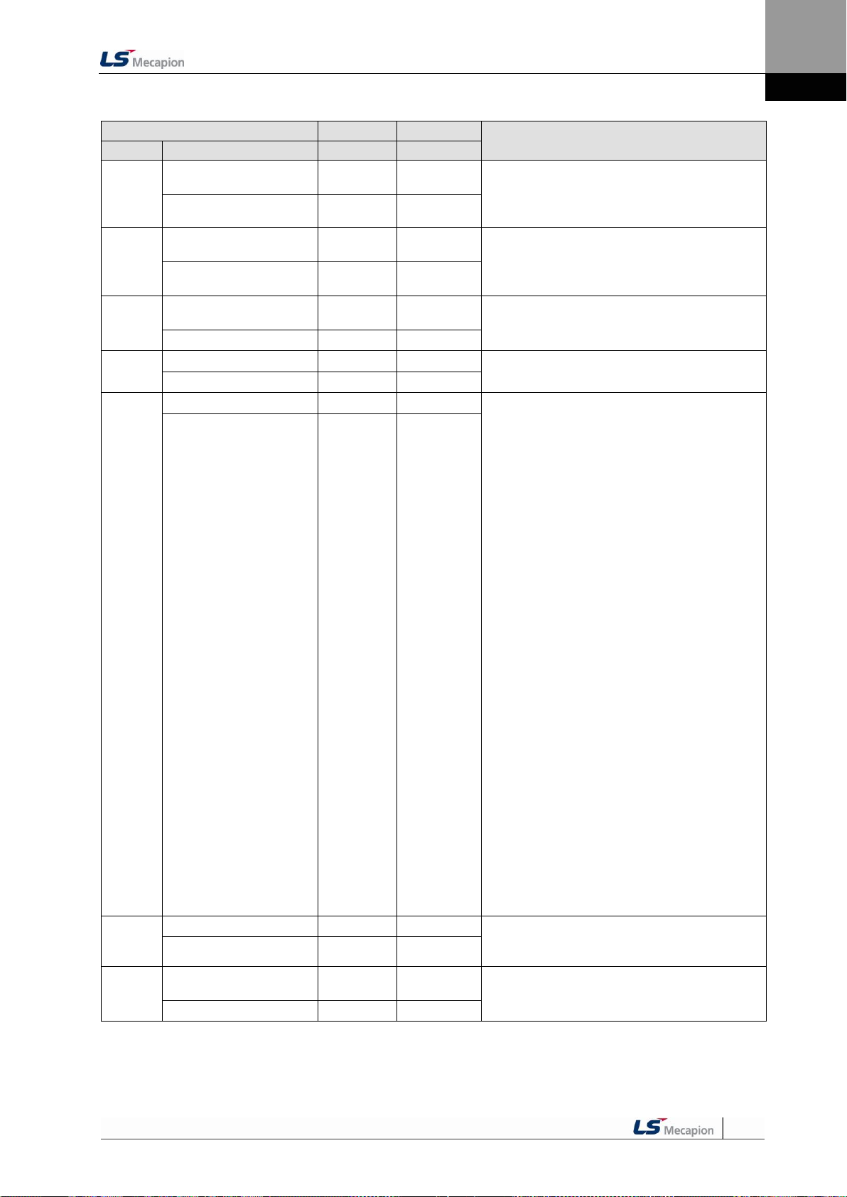
4. Parameters
Parameter
Unit
Initial
Details
Code
Name
Minimum
Maximum
P1-11
Speed feedback filter time
constant
0.1[ms]
5
Sets filter time constant for speed search values.
(Details: Refer to “4.4.2 Control Parameter Setting.”)
Spd. feedback filter time
constant
0
1000
P1-12
Torque command filter time
constant
[ms]
10
Sets filter time constant for torque command values.
(Details: Refer to “4.4.2 Control Parameter Setting.”)
Trq. command filter time
constant
0
1000
P1-13
Forward rotation torque
limit
[%]
300
Sets forward rotation torque limit.
(Details: Refer to “4.4.2 Control Parameter Setting.”)
Positive torque limit
0
300
P1-14
Negative torque limit
[%]
300
Sets negative torque limit.
(Details: Refer to “4.4.2 Control Parameter Setting.”)
Negative torque limit
0
300
P1-15
Gain transfer mode
-
0x00
Sets gain transfer mode. [0x0F (DIGIT 1)]
0: Use only gain 1.
1: ZSPD automatic gain transfer
In case of zero speed, transfer from gain 1 to
gain 2.
In the opposite case, transfer from gain 2 to gain
1.
2: INPOS automatic gain transfer
In case of IN position, transfer from gain 1 to gain
2.
In the opposite case, transfer from gain 2 to gain
1.
3: Manual gain transfer
When the gain 2 contact is on, transfer from gain
1 to gain 2.
In the opposite case, transfer from gain 2 to gain
1.
Sets P and PI control transfer modes. [0xF0 (DIGIT
2)]
0: Control PI only.
1: Control P if the command torque is higher than
the set torque [P1-24].
2: Control P if the command speed is higher than
the set speed [P1-25].
3: Control P if the current acceleration is higher
than the set acceleration [P1-26].
4: Control P if the current position error is higher
than the set position error [P1-27].
Control P if the PCON contact is on (highest
priority).
(Details: Refer to “4.4.2 Control Parameter Setting.”)
(Details: Refer to “4.4.4 Input/Output Contact
Parameter Setting.”)
Conversion mode
0x00
0x43
P1-16
Gain transfer time
[ms]
1
Sets gain transfer time during operation.
When converting gain 1 to gain 2 and gain 2 to gain
1, conversion is scheduled according to the set time.
Gain conversion time
1
100
P1-17
Resonance avoidance
operation
-
0
Select whether to use the notch filter or not.
0: Do not use. 1: Use
(Details: Refer to “4.4.2 Control Parameter Setting.”)
Notch filter use
0
1
4-35

4. Parameters
Parameter
Unit
Initial
Details
Code
Name
Minimum
Maximum
P1-18
Resonance avoidance
frequency
[Hz]
300
Sets resonance avoidance frequency.
(Details: Refer to “4.4.2 Control Parameter Setting.”)
Notch frequency
0
1000
P1-19
Resonance avoidance
range
[Hz]
100
Sets the scope of resonance avoidance frequency.
(Details: Refer to “4.4.2 Control Parameter Setting.”)
Notch bandwidth
0
1000
P1-20
Auto gain tuning speed
100
[RPM]
8
Sets speed for automatic gain tuning run.
Auto gain tuning Speed
1
10
P1-21
Auto gain tuning distance
-
3
Sets round-trip distance for automatic gain tuning run.
Auto gain tuning distance
1
5
P1-22
Torque control speed
limiting mode
-
0
Sets speed limit mode during torque control.
0: Limit to [P1-23]. 1: Maximum motor speed
2: Analog speed command
3: Limited to the smaller value between the value of
[P1-23] and the analog speed command.
Velocity limit switch
(torque control)
0
3
P1-23
Speed limit
[RPM]
2000
Sets speed limit when speed limit mode [P1-22] is 0
during torque control.
Velocity limit value
(torque control)
0
10000
P1-24
P control conversion torque
%
200
When setting P and PI control transfer mode [P1-15],
sets [0x10 (DIGIT 2)] P control conversion torque.
Torque switch value
(P control conversion)
0
300
P1-25
P control conversion speed
rpm
50
When setting P and PI control transfer mode [P1-15],
sets [0x20 (DIGIT 2)] P control conversion speed.
Speed switch value
(P control conversion)
0
6000
P1-26
P control conversion
acceleration
rpm/s
1000
When setting P and PI control transfer mode [P1-15],
sets [0x30 (DIGIT 2)] P control conversion
acceleration.
Acc. switch value
(P control conversion)
0
5000
P1-27
P control conversion
position error
pulse
2000
When setting P and PI control transfer mode [P1-15],
sets [0x40 (DIGIT 2)] P control conversion position
error .
Position Err switch value
(P control conversion)
0
10000
4-36
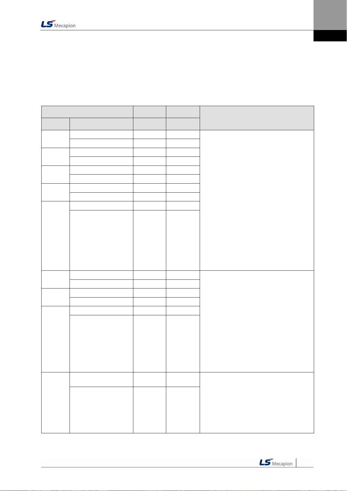
4. Parameters
Parameter
Unit
Initial
Details
Code
Name
Minimum
Maximum
**P2-00
Input signal definition 1
-
0x4321
Allocates a CN1 connector pin for a digital input
signal.
Initial input signal allocation
[P2-00]DIGIT 1 = SVON (DI1)
[P2-00]DIGIT 2 = SPD1 (DI2)
[P2-00]DIGIT 3 = SPD2 (DI3)
[P2-00]DIGIT 4 = SPD3 (DI4)
[P2-01]DIGIT 1 = ALARMST (DI5)
[P2-01]DIGIT 2 = DIR (DI6)
[P2-01]DIGIT 3 = CCWLIM (DI7)
[P2-01]DIGIT 4 = CWLIM (DI8)
[P2-02]DIGIT 1 = EMG (DI9)
[P2-02]DIGIT 2 = STOP (DIA)
[P2-02]DIGIT 3 = EGEAR1 (**)
[P2-02]DIGIT 4 = EGEAR2 (**)
[P2-03]DIGIT 1 = PCON (**)
[P2-03]DIGIT 2 = GAIN2 (**)
[P2-03]DIGIT 3 = P_CLR (**)
[P2-03]DIGIT 4 = T_LMT (**)
[P2-04]DIGIT 1 = MODE (**)
[P2-04]DIGIT 2 = ABS_RQ (**)
[P2-04]DIGIT 3 = ZCLAMP (**)
(**) Unallocated signals
(Details: Refer to “4.1.6 External Input Signal and
Logic Definition.”)
Input port define 1
0
0xFFFF
**P2-01
Input signal definition 2
-
0x8765
Input Port define 2
0
0xFFFF
**P2-02
Input signal definition 3
-
0x00A9
Input Port define 3
0
0xFFFF
**P2-03
Input signal definition 4
-
0x0000
Input Port define 4
0
0xFFFF
**P2-04
Input signal definition 5
-
0x0F00
Input Port define 5
0
0xFFFF
**P2-05
Output signal definition 1
-
0x4321
Allocate a CN1 connector pin for a digital output
signal.
Initial output signal allocation
[P2-05]DIGIT 1 = ALARM (DO1)
[P2-05]DIGIT 2 = READY (DO2)
[P2-05]DIGIT 3 = ZSPD (DO3)
[P2-05]DIGIT 4 = BREAK (DO4)
[P2-06]DIGIT 1 = INPOS (DO5)
[P2-06]DIGIT 2 = TLMT (**)
[P2-06]DIGIT 3 = VMLT (**)
[P2-06]DIGIT 4 = INSPD (**)
[P2-07]DIGIT 1 = WARN (**)
(**) Unallocated signals
(Details: Refer to “4.1.8 External Output Signal
and Logic Definition.”)
In case of dual allocation, the output contact
setting error [AL-72] occurs.
Output port define 1
0
0xFFFF
**P2-06
Output signal definition 2
-
0x0005
Output port define 2
0
0xFFFF
**P2-07
Output signal definition 3
-
0x0000
Output port define 3
0
0xFFFF
**P2-08
Input signal logic
definition 1
-
0b11111
Define CN1 connector logic for a digital input
signal. (0: Contact B. 1: Contact A)
Initial input logic definitions
[P2-08]DIGIT 1 = DI1 (CN1 #47) (Contact A)
[P2-08]DIGIT 2 = DI2 (CN1 #23) (Contact A)
[P2-08]DIGIT 3 = DI3 (CN1 #22) (Contact A)
[P2-08]DIGIT 4 = DI4 (CN1 #21) (Contact A)
[P2-08]DIGIT 5 = DI5 (CN1 #17) (Contact A)
(Details: Refer to “4.1.6 External Input Signal and
Logic Definition.”)
Input logic set 1
0
0b11111
4.2.5 Input/Output Setting Parameter
For detailed information, refer to "4.4.3 Analog Input/Output Parameter Setting" and "4.4.4
Input/Output Contact Parameter Setting."
“**” Modification is not possible with the servo on & Power reset parameter.
“*” Parameter that cannot be modified with the servo on
4-37

4. Parameters
Parameter
Unit
Initial
Details
Code
Name
Minimum
Maximum
**P2-09
Input signal logic
definition 2
-
0b10001
Define CN1 connector logic for a digital input
signal.(0: Contact B, 1: Contact A)
Initial input logic definitions
[P2-09]DIGIT 1 = DI6 (CN1 #46) (Contact A)
[P2-09]DIGIT 2 = DI7 (CN1 #20) (Contact A)
[P2-09]DIGIT 3 = DI8 (CN1 #19) (Contact A)
[P2-09]DIGIT 4 = DI9 (CN1 #18) (Contact A)
[P2-09]DIGIT 5 = DIA (CN1 #48) (Contact A)
(Details: Refer to “4.1.6 External Input Signal
and Logic Definition.”)
Input logic set 2
0
0b11111
**P2-10
Output signal logic
definition
-
0b10110
Define CN1 connector logic for a digital output
signal (0: Contact B, 1: Contact A)
Initial input logic definitions
[P2-10]DIGIT 1 = DO1 (CN #38/39) (Contact B)
[P2-10]DIGIT 2 = DO2 (CN #40/41) (Contact A)
[P2-10]DIGIT 3 = DO3 (CN #43) (Contact A)
[P2-10]DIGIT 4 = DO4 (CN #44) (Contact B)
[P2-10]DIGIT 5 = DO5 (CN #45) (Contact A)
(Details: Refer to “4.1.8 External Output Signal
and Logic Definition.”)
(Details: Refer to “4.4.4 Input/Output Contact
Parameter Setting.”)
Output logic set
0 0b11111
P2-11
Position reached output
range
[pulse]
10
Sets remaining pulse range for position reached
output in position operation mode.
(Details: Refer to “4.4.4 Input/Output Contact
Parameter Setting.”)
In position range
1
65535
P2-12
Zero speed output range
[RPM]
10
Sets speed range for zero speed output during a
stop.
(Details: Refer to “4.4.4 Input/Output Contact
Parameter Setting.”)
Zero speed range
1
500
P2-13
Range of output for speed
reached
[RPM]
10
Sets speed range for command speed reached
output.
(Details: Refer to “4.4.4 Input/Output Contact
Parameter Setting.”)
In speed range
1
500
P2-14
Brake output action speed
[RPM]
100
Sets speed for turning on the brake output
contact.
(Details: Refer to “4.4.4 Input/Output Contact
Parameter Setting.”)
Brake output speed
0
6000
P2-15
Brake output delay time
[ms]
500
Sets how much time to delay until the brake
output contact turns on when the servo is off or
stops.
(Details: Refer to “4.4.4 Input/Output Contact
Parameter Setting.”)
Brake output delay time
0
1000
P2-16
Position pulse clear mode
-
1
Select operation type for position pulse clear
(PCLR) mode.
0: Operate in edge mode.
1: Operate in level mode.
(Details: Refer to “4.4.4 Input/Output Contact
Parameter Setting.”)
PCLR mode
0
1
*P2-17
Analog speed scale
[RPM]
2000
Sets speed scale when the analog speed
command is 10 [V].
(Details: Refer to “4.4.3 Analog Input/Output
Parameter Setting.”)
Analog speed
command scale
1
6000
4-38

4. Parameters
Parameter
Unit
Initial
Details
Code
Name
Minimum
Maximum
P2-18
Analog speed offset
[mV]
0
Sets offset for analog speed commands.
(Details: Refer to “4.4.3 Analog Input/Output
Parameter Setting.”)
Analog speed
command offset
-1000
1000
P2-19
Zero speed clamp speed
[RPM]
0
Sets speed range for the clamp operation of the
analog zero speed command.
(Details: Refer to “4.4.3 Analog Input/Output
Parameter Setting.”)
Zero speed
clamp RPM
0
1000
*P2-20
Analog torque scale
[%]
100
Sets torque scale when the analog torque
command is 10 [V].
(Details: Refer to “4.4.3 Analog Input/Output
Parameter Setting.”)
Analog torque scale
1
350
P2-21
Analog torque command
offset
[mV]
0
Sets offset for analog torque commands.
(Details: Refer to “4.4.3 Analog Input/Output
Parameter Setting.”)
Analog torque
command offset
-1000
1000
P2-22
Zero torque clamp voltage
[mV]
75
Sets voltage range for the clamp operation of the
analog zero torque command.
(Details: Refer to “4.4.3 Analog Input/Output
Parameter Setting.”)
Zero torque clamp voltage
0
1000
4-39

4. Parameters
Parameter
Unit
Initial
Details
Code
Name
Minimum
Maximum
P3-00
Speed command 1
[RPM]
10
Sets 1-6 speed commands based on the speed
command input contact.
SPD
SD2
SPD3
Speed Control
OFF
OFF
OFF
Analog speed
command
ON
OFF
OFF
Digital speed
command 1
OFF
ON
OFF
Digital speed
command 2
ON
ON
OFF
Digital speed
command 3
OFF
OFF
ON
Digital speed
command 4
ON
OFF
ON
Digital speed
command 5
OFF
ON
ON
Digital speed
command 6
ON
ON
ON
Digital speed
command 7
(Details: Refer to “4.4.5 Speed Operation
Parameter Setting.”)
Speed command 1
-6000
6000
P3-01
Speed command 2
[RPM]
100
Speed command 2
-6000
6000
P3-02
Speed command 3
[RPM]
500
Speed command 3
-6000
6000
P3-03
Speed command 4
[RPM]
1000
Speed command 4
-6000
6000
P3-04
Speed command 5
[RPM]
1500
Speed command 5
-6000
6000
P3-05
Speed command 6
[RPM]
2000
Speed command 6
-6000
6000
P3-06
Speed command 7
[RPM]
3000
Speed command 7
-6000
6000
P3-07
Z detection operation speed
[RPM]
10
Sets Z detection operation speed.
Z search operation speed
1
300
P3-08
Speed command acceleration
time
[ms]
0
Sets acceleration time for speed commands.
(Details: Refer to “4.4.5 Speed Operation
Parameter Setting.”)
Speed command
ACC. time
0
10000
P3-09
Speed command deceleration
time
[ms]
0
Sets deceleration time for speed commands.
(Details: Refer to “4.4.5 Speed Operation
Parameter Setting.”)
Speed command DEC. time
0
10000
P3-10
Speed command S-curve
time
[ms]
10
Sets S-Curve time for speed commands.
Speed command
S-curve time
1
100
*P3-11
Speed operation pattern
-
0
Sets acceleration/deceleration type for speed
commands.
(0;Trapezoidal, 1;Sinusoidal)
(Details: Refer to “4.4.5 Speed Operation
Parameter Setting.”)
ACC.DEC. pattern
0
1
P3-12
Manual JOG operation speed
[RPM]
500
Sets operation speed for manual JOG operation
[Cn-00].
JOG operation speed
-6000
6000
4.2.6 Speed Operation Setting Parameter
For detailed information, refer to "4.4.5 Speed Operation Parameter Setting."
“**” Modification is not possible with the servo on & Power reset parameter.
“*” Parameter that cannot be modified with the servo on
4-40

4. Parameters
Parameter
Unit
Initial
Details
Code
Name
Minimum
Maximum
P3-13
Program JOG operation
speed 1
[RPM]
0
Sets operation speed/operation time for programs 1
to 4 during program JOG operation [Cn-01].
A test run repeats from step 1 to step 4.
Sets operation speed ([P3-13]-[P3-16]) and
operation time ([P3-17]-[P3-20]) for each step.
E.g.) Step 1 operation
Program jog speed 1
-6000
6000
P3-14
Program JOG operation
speed 2
[RPM]
3000
Program jog speed 2
-6000
6000
P3-15
Program JOG operation
speed 3
[RPM]
0
Program jog speed 3
-6000
6000
P3-16
Program JOG operation
speed 4
[RPM]
-3000
Program jog speed 4
-6000
6000
P3-17
Program JOG operation
time 1
[ms]
500
Program jog time 1
0
65535
P3-18
Program JOG operation
time 2
[ms]
5000
Program jog time 2
0
65535
P3-19
Program JOG operation
time 3
[ms]
500
Program jog time 3
0
65535
P3-20
Program JOG operation
time 4
[ms]
5000
Program jog time 4
0
65535
4-41

4. Parameters
Parameter
Unit
Initial
Details
Code
Name
Minimum
Maximum
**P4-00
Position input pulse
logic
-
0
Sets logic for position operation input pulses.
- The type of position command input pulses
and rotation direction per logic are as follows:
PULS
(CN1-9)
SIGN
(CN1-11)
PULS
(CN1-9)
SIGN
(CN1-11)
0
1
Phase
A + B
Positive
Logic
CW+CCW
Positive
Logic
PULS
(CN1-9)
SIGN
(CN1-11)
2
Pulse +
direction
positive
logic
Forward rotation Reverse rotation
PULS
(CN1-9)
SIGN
(CN1-11)
PULS
(CN1-9)
SIGN
(CN1-11)
PULS
(CN1-9)
SIGN
(CN1-11)
PF + PR
L Level
L Level
L Level
H Level
PULS
(CN1-9)
SIGN
(CN1-11)
PULS
(CN1-9)
SIGN
(CN1-11)
3
4
PULS
(CN1-9)
SIGN
(CN1-11)
5
Forward rotation
Phase
A + B
Negative
Logic
CW+CCW
Negative
Logic
Pulse +
direction
negative
logic
Reverse rotation
PULS
(CN1-9)
SIGN
(CN1-11)
PULS
(CN1-9)
SIGN
(CN1-11)
PF + PR
PULS
(CN1-9)
SIGN
(CN1-11)
H Level
H Level
H Level
L Level
E.g.) Relation between direction signals and
rotation directions when the position pulse
input logic is set to 2.
When the direction signal is low: Reverse
rotation (CW/clockwise)
When the direction signal is high: Forward
rotation (CCW/counterclockwise)
(Details: Refer to “4.4.6 Position Operation
Parameter Setting.”)
Pulse Input Logic
0
5
4.2.7 Position Operation Setting Parameter
For detailed information, refer to "4.4.6 Position Operation Parameter Setting."
“**” Modification is not possible with the servo on & Power reset parameter.
“*” Parameter that cannot be modified with the servo on
4-42

4. Parameters
Parameter
Unit
Initial
Details
Code
Name
Minimum
Maximum
*P4-01
Electronic gear ratio
numerator 1
-
1000
Sets electronic gear ratio numerator/denominator 0,
1, 2, and 3.
EGEAR
1
EGEAR
2
Electronic Gear
Ratio
Numerator /
Denominator
Electronic
Gear Ratio
OFF
OFF
Electronic gear
ratio numerator 0
Electronic
gear ratio 1
Electronic gear
ratio denominator 0
ON
OFF
Electronic gear
ratio numerator 1
Electronic
gear ratio 2
Electronic gear
ratio denominator 1
OFF
ON
Electronic gear
ratio numerator 2
Electronic
gear ratio 3
Electronic gear
ratio denominator 2
ON
ON
Electronic gear
ratio numerator 3
Electronic
gear ratio 4
Electronic gear
ratio denominator 3
The electronic gear ratio is the
numerator/denominator form of the relation
between the position command input pulse and
the motor encoder pulse. It is important to set
the ratio so that there is no error during position
operation.
(Details: Refer to “4.4.6 Position Operation
Parameter Setting.”)
Electric gear num.1
1
30000
*P4-02
Electronic gear ratio
numerator 2
-
1000
Electric gear num.2
1
30000
*P4-03
Electronic gear ratio
numerator 3
-
1000
Electric gear num.3
1
30000
*P4-04
Electronic gear ratio
numerator 4
-
1000
Electric gear num.4
1
30000
*P4-05
Electronic gear ratio
denominator 1
-
1000
Electric gear den.1
1
30000
*P4-06
Electronic gear ratio
denominator 2
-
2000
Electric gear den.2
1
30000
*P4-07
Electronic gear ratio
denominator 3
3000
Electric gear den.3
1
30000
*P4-08
Electronic gear ratio
denominator 4
-
4000
Electric gear den.4
1
30000
P4-09
Electronic gear ratio
mode
-
0
Select an electronic gear ratio mode.
0: Select electronic gear ratio 1-4.
1: Override offset [P4-10] on the electronic gear
ratio numerator 0.
(Details: Refer to “4.4.6 Position Operation
Parameter Setting.”)
Electric gear mode
0
1
P4-10
Electric gear ratio
numerator offset
-
0
Sets the offset of the electronic gear ratio numerator
0.
The offset will be set on the electronic gear ratio
numerator 0.
EGEAR1 contact LOW -> HIGH
: Increase the electronic gear ratio numerator by
1.
EGEAR2 contact LOW -> HIGH
: Decrease the electronic gear ratio numerator
by 1)
(Details: Refer to “4.4.6 Position Operation
Parameter Setting.”)
Electric gear num.
offset
-30000
30000
P4-11
Position error
[Pulse]
90000
Sets range for triggering the position error alarm.
(Details: Refer to “4.4.4 Input/Output Contact
Parameter Setting.”)
Following error range
1
2^30
P4-12
Limit contact function
-
0
Select the operation type of position command pulse
clear for CWLIM and CCWLIM contacts.
0: When the CCWLIM / CWLIM contact is on,
receive an input pulse and save it to buffer.
1: Ignore any input pulse when the CCWLIM /
CWLIM contact is on.
Position limit
function
0
1
4-43

4. Parameters
Parameter
Unit
Initial
Details
Code
Name
Minimum
Maximum
P4-13
Backlash
compensation
-
0
Sets backlash compensation in position
operation.
Sets backlash compensation by converting the
amount of backlashes to number of pulses if the
position changes because of backlashes
caused by position operation.
Sets in the opposite direction according to the
amount of backlashes.
(Details: Refer to “4.4.6 Position Operation
Parameter Setting.”)
Backlash
compensation
0
10000
P4-14
Pulse input filter
-
3
Sets filter frequency according to pulse input.
0 : No filter used
1 : 500 Khz (Min)
2 : 750 Khz
3 : 1 Mhz (Default)
4 : 1.25 Mhz
The frequency bands above were determined
based on the width of input pulse in
consideration of the characteristics of digital
filters.
Pulse input filter
0
4
4-44

4. Parameters
Parameter
Unit
Initial
Details
Code
Name
Minimum
Maximum
Cn-00
Manual JOG operation
-
-
The drive performs manual JOG operation
by itself.
(Refer to “Chapter 5 Handling and
Operation.”)
[MODE]: Finish
[UP]: Forward rotation (CCW)
[DOWN]: Reverse rotation (CW)
[SET]: Servo ON / OFF
Related parameters are as follows:
[P3-08]: Speed command acceleration
time
[P3-09]: Speed command deceleration
time
[P3-10]: Speed command S-curve
[P3-11]: Speed operation pattern
[P3-12]: JOG operation speed
Operate regardless of the contact input
status of CN1.
(Details: Refer to “4.4.5 Speed Operation
Parameter Setting.”)
(Details: Refer to "5.2 Handling.")
Jog
-
-
Cn-01
Program JOG operation
-
-
Continuously operates according to the
program already set.
[SET]: Program JOG run or stop
Related parameters are as follows:
[P3-08]: Speed command acceleration
time
[P3-09]: Speed command deceleration
time
[P3-10]: Speed command S-curve
[P3-11]: Speed operation pattern
[P3-13~16]: Program operation speed 1
to 4
[P3-17~20]: Program operation time 1 to
4
Operate regardless of the contact input
status of CN1.
(Details: Refer to “4.4.5 Speed Operation
Parameter Setting.”)
(Details: Refer to "5.2 Handling.")
Program jog
-
-
Cn-02
Alarm reset
-
-
Reset the alarm that went off.
(Details: Refer to "5.2 Handling.")
Alarm reset
-
-
4.2.8 Operation Handling Parameter
“**” Modification is not possible with the servo on & Power reset parameter.
“*” Parameter that cannot be modified with the servo on
4-45

4. Parameters
Parameter
Unit
Initial
Details
Code
Name
Minimum
Maximum
Cn-03
Get alarm history
-
-
Check the saved alarm code history.
[UP] or [DOWN]: Reads alarm codes.
E.g.) Recent first history [AL-42]:
RST_PFAIL occurs.
01: Latest alarm
20: 20th previous alarm
(Details: Refer to "5.2 Handling.")
Get alarm history
-
-
Cn-04
Alarm history reset
-
-
Deletes the entire saved alarm code history.
(Details: Refer to "5.2 Handling.")
Alarm history clear
-
-
Cn-05
Auto gain tuning
-
-
Performs automatic gain tuning operation.
Related parameters are as follows.
[P1-22]: Auto gain tuning speed
[P1-23]: Auto gain tuning distance
(Details: Refer to "5.2 Handling.")
Auto gain tuning
-
-
Cn-06
Z search
-
-
Perform Z detection.
[SET]: Mode entering and servo ON status
[UP]: Phase Z forward search
[DOWN]: Phase Z reverse search
Related parameters are as follows.
[P3-07]: Sets Z-phase search operation
speed [RPM].
(Details: Refer to "5.2 Handling.")
Z detection
-
-
Cn-07
Input contact forced
ON/OFF
-
-
Forcibly turns on/off the input contact
temporarily.
[UP]: (A),(8),(6),(4), and (2) signals forced
ON/OFF
[DOWN]: (9),(7),(5),(3), and (1) signals
forced ON/OFF
[MODE]: Move to another digit.
(Details: Refer to "5.2 Handling.")
Forced input test
-
-
Cn-08
Output contact forced
ON / OFF
-
-
Forcibly turns on/off the output contact
temporarily.
[UP]: (4) and (2) signals forced ON/OFF
[DOWN]: (5),(3), and (1) signals forced
ON/OFF
[MODE]: Move to another digit.
(Details: Refer to "5.2 Handling.")
Forced output test
-
-
Cn-09
Parameter initialization
-
-
Initializes parameter data.
(Details: Refer to "5.2 Handling.")
Parameter Initialization
-
-
4-46
 Loading...