


Right choice for ultimate yield
LSIS strives to maximize customers' profit in gratitude of choosing us for your partner.
Programmable Lo gic C ontroller
XGR CPU Modul e
User’s Manual
Read this manual carefully before
wiring, operating, servicing or
Keep this manual within easy reach for
CPU
Expansion drive
XGT Series
XGR-CPUH/F
XGR-CPUH/T
XGR-CPUH/S
XGR-DBST
XGR-DBSF(S)
XGR-DBSH(S)
XGR-DBDT
XGR-DBDF
XGR-DBDH
installing,
inspecting this equipment.
quick reference.
http://www.lsis.com

Safety Instructions
Warning
Caution
Before using the product …
For your safety and effective operation, please read the safety instructions
thoroughly before using the product.
► Safety Instructions should always be observed in order to prevent accident
or risk with the safe and proper use the product.
► Instructions are separated into “Warning” and “Caution”, and the meaning of
the terms is as follows;
WARNING indicates a potentially hazardous situation which,
if not avoided, could result in death or serious injury
CAUTION indicates a potentially hazardous situation which,
if not avoided, may result in minor or moderate injury.
It may also be used to alert against unsafe practices
► The marks displayed on the product and in the user’s manual have the
following meanings.
Be careful! Danger may be expected.
Be careful! Electric shock may occur.
► The user’s manual even after read shall be kept available and accessible to
any user of the product.

Safety Instructions
damage such as emergent stop switch,
protection circuit, the upper/lowest limit switch, forward/reverse
etc.) is detected during CPU operation in PLC, the whole output is
designed to be turned off and stopped for system safety. However,
in case CPU error if caused on output device itself such as relay or
detected, the output may be kept on, which may
In case of data exchange between computer or other external
Warning
Safety Instructions when designing
Please, install protection circuit on the exterior of PLC to protect
the whole control system from any error in external power or PLC
module. Any abnormal output or operation may cause serious problem
in safety of the whole system.
- Install applicable protection unit on the exterior of PLC to protect
the system from physical
operation interlock circuit, etc.
- If any system error (watch-dog timer error, module installation error,
TR can not be
cause serious problems. Thus, you are recommended to install an
addition circuit to monitor the output stat us.
Never connect the overload than rated to the output module nor
a llow the output circuit to have a short circuit, which may cause a
fire.
Never let the external power of the output circuit be designed to
be On earlier than PLC power, which may cause abnormal output or
operation.
equipment and PLC through communication or any operation of
PLC (e.g. operation mode change), please install interlock in the
sequence program to protect the system from any error. If not, it
may cause abnormal output or operation.

Safety Instructions
Caution
product is installed loosely or incorrectly, abnormal operation, error or
Caution
Safety Instructions when designing
I/O signal or communication line shall be wired at least 100mm
away from a high-voltage cable or power line. If not, it may cause
abnormal output or operati o n.
Safety Instructions when designing
Use PLC only in the environment specified in PLC manual or
general standard of data sheet. If not, electric shock, fire, abnormal
operation of the product or flames may be caused.
Before installing the module, be sure PLC power is off. If not,
electric shock or damage on the product may be caused.
Be sure that each module of PLC is correctly secured. If the
dropping may be caused.
Be sure that I/O or extension connecter is correctly secured. If
not, electric shock, fire or abnormal operation may be caused.
If lots of vibration is expected in the installation environment,
don’t let PLC directly vibrated. Electric shock, fire or abnormal
operation may be caused.
Don’t let any metallic foreign materials inside the product, which
may cause electric shock, fire or abnormal operation..

Safety Instructions
damage on the product may be
Before PLC system is powered on, be sure that all the covers of
Warning
Let the wiring installed correctly after checking the voltage rated
Caution
Safety Instructions when wir ing
Prior to wiring, be sure that power of PLC and external power is
turned off. If not, electric shock or
caused.
the terminal are securely closed. If not, electric shock may be c aused
of each product and the arrangement of terminals. If not, fire,
electric shock or abnormal operati on may be c ause d.
Secure the screws of terminals tightly with specified torque when
wiring. If the screws of terminals get loose, short circuit, fire or abnormal
operation may be caused.
*
Surely use the ground wire of Class 3 for PE terminals, which is
exclusively used for PLC. If the terminals not grounded correctly,
abnormal operation may be caused.
Don’t let any foreign materials such as wiring waste inside the
module while wiring, which may cause fire, damage on the product
or abnormal operation.

Safety Instructions
If not, electric shock or
Warning
Caution
Product or battery waste shall be processed as industrial waste.
Caution
Safety Instruct ions for test-operation or repair
Don’t touch the terminal when powered. Electric shock or abnormal
operation may occur.
Prior to cleaning or tightening the terminal screws, let all the
external power off including PLC power.
abnormal operation may occur.
Don’t let the battery recharged, disassembled, heated, short or
soldered. Heat, explosion or ignition may cause injuries or fire.
Don’t remove PCB from the module case nor remodel the module.
Fire, electric shock or abnormal operation may occur.
Prior to installing or disassembling the module, let all the external
power off including PLC power. If not, electric shock or abnormal
operation may occur.
Keep any wireless installations or cell phone at least 30cm away
from PLC. If not, abnormal operation may be caused.
Safety Instructions for waste disposal
The waste may discharge toxic materials or explode itself.

1
(3) Flag
A-6, A-11
2-4
Revision History
Revision History
Version Data Main contents Revised location
V 1.0 ’08. 6 First Edition -
V 1.1 ’08.7
1. Modifying contents
(2) How to configure redundancy system
(3) Performance specification
(4) S can Time
(5) Program memory
(6) I/O mod ule skip fu nction
(7) Module changing wizard during RUN
(8) Performance specification
(9) E xample of calculating consumption current/power
(10) Caution in handling
(11) Grounding
2. Adding contents
(1) XGR redundancy system configuration
(2) Remote I/O system
(3) Scan Time
(4) I/O module skip
3. Deleting contents
-
2-5
4-1,4-2
5-6,5-8
5-28
6-19,6-20
6-21
7-1,7-3
8-5
11-5
11-13
-
1-3
2-13
5-8
6-20
-
V 1.2 ’09.9
V 1.3 ’09.9
(1) Max install-able module number in specification
1. Modifying contents
(1) Performance specification
(2) redundancy parameter setting window
1. Adding contents
(1) Contents on redundancy system communication
operation setting (ONE IP Solution)
2. modifying contents
(1) Product list (add new products)
- XGR-DC32, XGR-DMMA
- XGF-SOEA
- XGL-EIPT
7-1
-
4-2
5-2, CH6
6-18~20
2-1
2-3

2
(5) Modifying contents on basic parameter
Ch6.7.1
(4) Base and expansion cable
Ch101.1
Revision History
Version Data Main contents Revised location
V 1.4 ’09.12
V 1.5 ’10.03
V 1.6 ’10.10
1. Adding contents
(1) adding contents related to DC power
1. Adding contents
(1) Contents on reset/D.Clear
(2) Contents on Cnet/FEnet module equipment
(3) Contents on redundancy parameter
(4) Warning flag
(5) Smart Link wiring diagr am and Event input m odule
specifications
2. Modifying contents
(1) Contents on parameter setting window
(2) Contents on Fault mask setting
(3) Module replacement
1. Modifying contents
(1) Modifying contents
(2) Adding contents
Ch8.1, Ch8.2, Ch8.3
4-6
2-7
5-8~9
App-8
9-24~25
5-4, 6-1, 6-14~15
6-20
6-23~24
Ch3.1
Ch5.1.2
V 1.7 ’10.10
V 1.8 ’10.10
(3) Adding modules
(4) Modifying contents on redundancy parameter
1. Modifying contents
(1) Overview
(2) System configuration
(3) Power module
1. Adding contents
(1) Adding contents on redundancy parameter
(2) Adding contents on redundancy parameter
(3) Adding contents on redundancy parameter
Ch5.1.4
Ch5.1.4
Ch1.1
Ch2.1
Ch8.4.1
Ch5.1.4
Ch6.8.1
Ch6.9

3
(4) Adding optical single module
1-1, 2-1, 2-6, 4-1, 4-2, 7-1
(1) Removing Appendix 1.11
App-21
(1) Vibration resistance S pecifications
3-1
(6) List of Configuration Products updated
Revision History
Version Data Main contents Revised location
V 1.9 ’11.06
V 2.0 ’13.01
V 2.1 ’14.06
1. Adding contents
(1) Adding module on Extension redundancy
(2) Adding contents on Extension redundancy
(3) Adding contents on Flag
1. Adding contents
(1) Adding Redundancy Expansion Base
(2) Built-in PID Function
2.Modifying contents
(1) Modifying EtherNet/IP
(2) Modifying U, K Device memory
3. Re moving conten ts
1. Adding contents
(1) Adding _REFRESH_NG_BASE
1-1, 2-1, 7-2
1-3, 1-4, 2-8, 6-25,
8-3, 10-2, 14-28
App-3/7/11/13
2-1, 10-1
Ch 14
1-6, 2-7, 2-13
4-1, 5-32
App-13
V 2.2 ’15.07
V 2.3 ‘15.09
V 2.4 ‘16.03
※ The number of User’s manual is indicated right part of the back cover.
ⓒ LSIS Co., Ltd 2008 All Rights Reserved.
1.Modifying content s
1.Modifying content s
(1) Rated input voltage modified
(2) Circuit configuration modified
(3) Smart Link Model name modified
(4) Terminology modified (FG PE)
(5) CPU Processing Speed Unit changed (us ns)
1.Modifying contents
(1) Smart Link manual supplemented
8-1
9-2, 9-3, 9-4, 9-5
9-6
8-2, 10-1, 10-2, 11-2, 13-1
4.1
2.1
9-6

7
Manual
online functions such as programming, printing,
About User’s Manual
About User’s Manual
Thank you for purchasing PLC of LSIS Co., Ltd.
Before use, mak e sure to caref ully read an d understan d the Us er’s Manu al about the functions,
performances, insta llation and programming of th e product you purchased in or der for correct
use and importantly, let the end user and maintenance administrator to be provided with the
User’s Manual.
The User’s Manual describes the product. If necessary, you may refer to the following
description and order accordingly. In ad dition, you may con nect our website(
and download the information as a PDF file.
Relevant User’s Manuals
Title Description
It describes how to use XG5000 software, which it is
XG5000 User’s
Manual
(for XGI/XGR)
XGI / XGR Series
Instructions &
Programming
applied to the IEC standar d language, especially about
monitoring and debugging by using XGI/XGR series
products.
It is the user’s manual for programming to explain ho w
to use commands that are used PLC system with XGI
CPU and XGR CPU.
http://eng.lsis.biz/)
No. of User’s
10310000834
10310000833
XGI-CPU User’s
Manual
It describes CPU specif ications and technical terms for
the XGT PLC system using a series of XGI-CPU.
10310000832

1
◎
◎
TABLE OF CONTENTS
TABLE OF CONTENTS
Chapter 1 Overview ......................................................................................................................... 1-1~1-8
1.1 About this User Manual ................................................................................................................... 1-1
1.2 Configuration o f the XGR Redundant System .................................................................................. 1-3
1.3 Features of the XGR Redundancy system ....................................................................................... 1-4
1.4 Glossary ........................................................................................................................................... 1-6
Chapter 2 System Configuration.................................................................................................... 2-1~2-17
2.1 Product List ........................................................................................................................................ 2-1
2.2 Redundancy System ....................................................................................................................... 2-7
2.2.1 Redundant System Configuration ............................................................................................. 2-7
2.2.2 Redundancy of CPU sy stem .................................................................................................. 2-9
2.2.3 Power Module Redundancy ..................................................................................................2-11
2.2.4 Extension Drive Redundancy ............................................................................................... 2-12
2.2.5 Extension Base Communication Path Redundancy ............................................................. 2-12
2.2.6 Example of Redundant System Configuration .................................................................... 2-12
2.3 Network System .............................................................................................................................. 2-17
2.3.1 Networking among Systems ................................................................................................. 2-17
2.3.2 Remote I/O Sy stem ................................................................................................................ 2-17
Chapter 3 General Specifications ............................................................................................................ 3-1
3.1 General S pecifications ....................................................................................................................... 3-1
Chapter 4 CPU Module ................................................................................................................... 4-1~4-8
4.1 Performance S pecifications ............................................................................................................... 4-1
4.2 Names and Functions of Parts .......................................................................................................... 4-3
4.3 Battery ............................................................................................................................................... 4-7
4.3.1 Battery specifications ................................................................................................................ 4-7
4.3.2 Cautions for usage .................................................................................................................... 4-7
4.3.3 Battery life ................................................................................................................................. 4-7
4.3.4 Replacement ............................................................................................................................. 4-8
Chapter 5 Program Constitution and Operation Method ............................................................... 5-1~5-33
5.1 Program Basics ............................................................................................................................... 5-1
5.1.1 Program S tructure and Execution ........................................................................................... 5-1
5.1.2 Software Program Execution Methodology ............................................................................ 5-2
5.1.3 Operation of instantaneous interrupt ......................................................................................... 5-5
5.1.4 Scan Time ................................................................................................................................. 5-6
5.2 Program Execution .........................................................................................................................5-11

2
TABLE OF CONTENTS
5.2.1 Program T ype ..........................................................................................................................5-11
5.2.2 Program Execution ..................................................................................................................5-11
5.2.3 Restart Mode ......................................................................................................................... 5-12
5.2.4 Tas k Progra m ........................................................................................................................ 5-14
5.3 Operation Mode............................................................................................................................... 5-23
5.3.1 Operation Mode .................................................................................................................... 5-23
5.3.2 RUN mode .............................................................................................................................. 5-23
5.3.3 S top M ode ............................................................................................................................... 5-24
5.3.4 Debug Mode ........................................................................................................................... 5-25
5.3.5 Switching Operation Mode .................................................................................................... 5-25
5.4 Redundancy System Operation .................................................................................................... 5-27
5.4.1 Redundancy System Operation ............................................................................................. 5-27
5.4.2 Start-up of Redundant System ................................................................................................ 5-29
5.5 Memory ........................................................................................................................................... 5-31
5.5.1 Program memory .................................................................................................................... 5-31
5.5.2 Data memory .......................................................................................................................... 5-32
5.5.3 Data retain area setting ........................................................................................................... 5-32
Chapter 6 CPU Module Functions ................................................................................................. 6-1~6-24
6.1 Self-dia gnosis Function ..................................................................................................................... 6-1
6.1.1 Scan watchdog timer ................................................................................................................ 6-1
6.1.2 I/O Module Check Function ...................................................................................................... 6-3
6.1.3 Battery level check .................................................................................................................... 6-3
6.1.4 Saving error log ......................................................................................................................... 6-3
6.1.5 Troubleshooting ........................................................................................................................ 6-3
6.2 Clock Function ................................................................................................................................... 6-4
6.3 Remote Functions ............................................................................................................................. 6-7
6.4 Forced On/Off Function of I/O ......................................................................................................... 6-10
6.4.1 Force I/O Setting ..................................................................................................................... 6-10
6.4.2 The point of time of method o f forced On/Off process .............................................................6-11
6.5 Operation history saving function .................................................................................................... 6-12
6.5.1 Error history ............................................................................................................................. 6-12
6.5.2 Mode change history .............................................................................................................. 6-12
6.5.3 Shut down history ................................................................................................................... 6-12
6.5.4 System history......................................................................................................................... 6-12
6.6 External device failure diagnosis function ........................................................................................ 6-13
6.7 Redundancy system operation mode ............................................................................................. 6-14
6.7.1 Operation mode setting ........................................................................................................... 6-14
6.7.2 Data synchronization area setting ........................................................................................... 6-16
6.8 Setting operation of communication .............................................................................................. 6-17
6.8.1 Automatic master conversion ................................................................................................ 6-17
6.8.2 Global status variable .............................................................................................................. 6-18
6.8.3 ONE IP Solution ...................................................................................................................... 6-18
6.9 Fault Mask Function ...................................................................................................................... 6-20
6.9.1 Applications and operations .................................................................................................... 6-20
6.9.2 Fault mask setting ................................................................................................................... 6-20
6.9.3 Releasing fault mask ............................................................................................................... 6-20
6.10 I/O M odule Skip Function .............................................................................................................. 6-21
6.10.1 Applications and operations .................................................................................................. 6-21
6.10.2 Setting and processing I/O data ............................................................................................ 6-21
6.10.3 Releasing skip function ......................................................................................................... 6-21
6.11 I/O Base Skip Function .................................................................................................................. 6-22

3
TABLE OF CONTENTS
6.11.1 Purpose and outline of the operation .................................................................................... 6-22
6.11.2 Setting method ...................................................................................................................... 6-22
6.11.3 Releasing skip function ......................................................................................................... 6-22
6.12 Module Replacement Function during Operation ......................................................................... 6-23
6.12.1 Module replacement in redundant system............................................................................ 6-23
6.12.2 Replacing I/O module in redundant system .......................................................................... 6-23
6.12.3 Replacing base module in redundant system ...................................................................... 6-24
Chapter 7 Extension Drive Module .................................................................................................. 7-1~7-3
7.1 Performance specifications ............................................................................................................... 7-1
7.2 Identification and Function ................................................................................................................. 7-2
Chapter 8 Power Module ................................................................................................................. 8-1~8-5
8.1 T y pe and S pecification ....................................................................................................................... 8-1
8.2 Parts’ Names ..................................................................................................................................... 8-2
8.3 Selection ............................................................................................................................................ 8-3
8.4 Examples of Current Consumption/Power Calculations ................................................................... 8-4
Chapter 9 IO Module ..................................................................................................................... 9-1~9-40
9.1 Cautions for Selecting Modules ......................................................................................................... 9-1
9.2 Digital Input Module S pecifications .................................................................................................... 9-3
9.2.1 8 point DC24V input module(source/sink type) ........................................................................ 9-3
9.2.2 16 point DC24V input module(source/sink type) ...................................................................... 9-4
9.2.3 16 point DC24V input module(source type) .............................................................................. 9-5
9.2.4 32 point DC24V input module(source/sink type) ...................................................................... 9-6
9.2.5 32 point DC24V input module(source type) .............................................................................. 9-7
9.2.6 64 point DC24V input module(source/sink type) ...................................................................... 9-8
9.2.7 64 point DC24V input module(source type) .............................................................................. 9-9
9.2.8 16 point AC110V input module ............................................................................................... 9-10
9.2.9 8 point AC220V input module ..................................................................................................9-11
9.2.10 8 point AC220V isolated input module .................................................................................. 9-12
9.3 Digital Output Module S pecifications ............................................................................................... 9-13
9.3.1 8 point relay output module ..................................................................................................... 9-13
9.3.2 16 point relay output module ................................................................................................... 9-14
9.3.3 16 point relay output module(Surge Killer built-in type) ........................................................... 9-15
9.3.4 16 point Triac output module ................................................................................................... 9-16
9.3.5 16 point transistor output module(sink type) ........................................................................... 9-17
9.3.6 32 point transistor output module(sink type) ........................................................................... 9-18
9.3.7 64 point transistor output module(sink type) ........................................................................... 9-19
9.3.8 16 point transistor output module(source type) ....................................................................... 9-20
9.3.9 32 point transistor output module(source type) ....................................................................... 9-21
9.3.10 64 point transistor output module(source type) ..................................................................... 9-22
9.3.11 8 point transistor isolated output module(sink type) .............................................................. 9-23
9.4 Digital I/O Combined Module S pecifications. .................................................................................. 9-24
9.4.1 32 point(DC input transistor output) I/O combined module ..................................................... 9-24
9.5 Event Input Module ......................................................................................................................... 9-25
9.5.1 Event input module ................................................................................................................. 9-25

4
TABLE OF CONTENTS
9.6 Applications of Smart Link ............................................................................................................... 9-26
9.6.1 Modules accessible to Smart Link .......................................................................................... 9-26
9.6.2 Smart Link Components ......................................................................................................... 9-26
9.6.3 Smart Link Mapping T able ...................................................................................................... 9-27
9.6.4 Smart Link Connection............................................................................................................ 9-27
9.6.5 Smart Link Connection Diagram ............................................................................................. 9-28
9.6.6 Smart Link Specifications & Dimensions ................................................................................ 9-38
Chapter 10 Base and Extension Cable ....................................................................................... 10-1~10-5
10.1 Specifications ................................................................................................................................. 10-1
10.1.1 Basic base ............................................................................................................................ 10-1
10.1.2 Extension base ..................................................................................................................... 10-1
10.1.3 Sync. Cable ........................................................................................................................... 10-2
10.1.4 Extension cable ..................................................................................................................... 10-2
10.1.5 Connector for extension cable (electrical) ............................................................................. 10-3
10.2 Parts and Names ........................................................................................................................... 10-4
10.2.1 Basic base ............................................................................................................................ 10-4
10.2.2 Extension base ..................................................................................................................... 10-5
Chapter 11 Installation and Wiring .............................................................................................. 11-1~11-13
11.1 Installation .......................................................................................................................................11-1
11.1.1 Inst allation environment ..........................................................................................................11-1
11.1.2 Cautions for handling .............................................................................................................11-3
11.1.3 Attachment/Detachment of modules ......................................................................................11-8
11.2 Wiring ........................................................................................................................................... 11-10
11.2.1 Power wiring ........................................................................................................................ 11-10
11.2.2 I/O Device wiring .................................................................................................................. 11-11
11.2.3 G rounding wiring ................................................................................................................. 11-12
11.2.4 S pecifications of wiring cable ............................................................................................... 11-13
Chapter 12 Maintenance ............................................................................................................. 12-1~12-2
12.1 Repairs and Maintenance ............................................................................................................. 12-1
12.2 Routine Inspection ......................................................................................................................... 12-1
12.3 Periodic Inspection ........................................................................................................................ 12-2
Chapter 13 EMC Compliance. ..................................................................................................... 13-1~13-4
13.1 Requirements Complying with EMC Specifications .................................................................... 13-1
13.1.1 EMC specifications ............................................................................................................... 13-1
13.1.2 Panel ..................................................................................................................................... 13-2
13.1.3 Cable ..................................................................................................................................... 13-3
13.2 Requirements Complying with Low Voltage Direction .................................................................. 13-4
13.2.1 Specifications applicable to XGT series ................................................................................ 13-4
13.2.2 Selection of XGT series PLC ................................................................................................ 13-4

5
TABLE OF CONTENTS
Chapter 14 Built-in PID Function ............................................................................................... 14-1~14-37
14.1 Features ........................................................................................................................................ 14-1
14.2 PID Control .................................................................................................................................... 14-1
14.3 PID Control Operation ................................................................................................................... 14-2
14.3.1 Terms used ........................................................................................................................... 14-2
14.3.2 PID equation ......................................................................................................................... 14-2
14.3.3 P control ................................................................................................................................ 14-3
14.3.4 PI control ............................................................................................................................... 14-4
14.3.5 PID control ............................................................................................................................ 14-5
14.4 PID Instructi on ............................................................................................................................... 14-6
14.4.1 PID loop state ........................................................................................................................ 14-6
14.4.2 PID instruction group ............................................................................................................. 14-7
14.5 PID Configuration .......................................................................................................................... 14-9
14.5.1 Common bit area ................................................................................................................ 14-12
14.5.2 Individual data operation ..................................................................................................... 14-15
14.6 Convenient Functions of PID Instruction ..................................................................................... 14-22
14.6.1 Various control method including PID ................................................................................. 14-22
14.6.2 Operation and function of Anti Wind-UP ............................................................................. 14-22
14.6.3 Operation and function of Auto-tuning ................................................................................ 14-22
14.6.4 Operation and function of cascade ..................................................................................... 14-23
14.7 Directions of PID Instructions ...................................................................................................... 14-24
14.7.1 Hardware configuration ....................................................................................................... 14-24
14.7.2 Program example 1 ............................................................................................................ 14-27
14.7.3 PID control .......................................................................................................................... 14-28
14.7.4 AT(Auto-tuning) operation ................................................................................................... 14-35
14.7.5 Program example 2 ............................................................................................................ 14-36
14.7.6 Cascade operation .............................................................................................................. 14-37
Chapter 15 Troubleshooting ...................................................................................................... 15-1~15-27
15.1 Basic Troubleshooting Procedure ................................................................................................. 15-1
15.2 Troubleshooting ............................................................................................................................. 15-2
15.2.1 Action when POWER LED is off ........................................................................................... 15-3
15.2.2 A ction when WA R. (Warning) LED is on ............................................................................... 15-4
15.2.3 A ction when ERR. LED is on. ............................................................................................... 15-8
15.2.4 A ction when RUN/STOP LED is off ...................................................................................... 15-9
15.2.5 A cton when I/O module does not work properly ................................................................. 15-10
15.2.6 Action when writing program is not possible ....................................................................... 15-12
15.2.7 Action when Sync. cable is not installed properly ............................................................... 15-13
15.2.8
When undesirable master switching occurs ....................................................................... 15-14
15.2.9 When newly added CPU does not join redundant operation ............................................. 15-15
15.2.10 When failing to switch master ........................................................................................... 15-16
15.2.11 When extension cable is disconnected ........................................................................... 15-17
15.2.12
When extension driver gets er ror ............................................................................... 15-19
15.3 Troubleshooting Questionnaires ................................................................................................. 15-21
15.4 Cases .......................................................................................................................................... 15-22
15.4.1 Trouble types and measures of input circuit ....................................................................... 15-22
15.4.2 Trouble types and measures of output circuit ..................................................................... 15-23
15.5 Error Codes List ........................................................................................................................... 15-25
15.5.1 Error codes during CPU operation ...................................................................................... 15-25

6
TABLE OF CONTENTS
Appendix 1 Flags List ............................................................................................................ App-1~App-18
Appendix 1.1 User Flag ....................................................................................................................... App-1
Appendix 1.2 System Error Representative Flag ................................................................................ App-2
Appendix 1.3 System Error Detail Flag ............................................................................................... App-6
Appendix 1.4 System Warning Representative Flag .......................................................................... App-8
Appendix 1.5 System Warning Detail Flag ........................................................................................ App-10
Appendix 1.6 System Operation Status Information Flag ................................................................. App-11
Appendix 1.7 Redundant Operation Mode Information Flag ............................................................ App-16
Appendix 1.8 Operation Result Information Flag .............................................................................. App-17
Appendix 1.9 Operation mode Key S tatus Flag ................................................................................ App-18
Appendix 1.10 Link Flag (L) List ........................................................................................................ App-19
Appendix 1.11 Reserved Word ......................................................................................................... App-21

1-1
XGR−AC12, XGR-AC22, XGR-AC13, XGR-AC23, XGR-DC42
XGR-DBDT, XGR-DBDF, XGR-DBDH
Chapter 1. Overview
Chapter 1. Overview
1.1 About this User Manual
This User Manual describes the performance speci fications and operation procedures of the redundancy system including the XGR-CPU, in
addition to the configuration of communication system and the use of special module in relation to the redundancy system.
This User Manual provides the basic specificati ons of the CPU module, power module, I/O modul e, main/expansion base of redundancy and
expansion drive module, which are applied to the ba sic system of redundancy (XGR).
Classification Model Name
Redundancy CPU Modul e
Expansion D rive Module
Redundancy Pow er Module
I/O Module
Redundancy Ba sic Ba se
Redundancy Expansion Base
Redundancy Expansion Drive Modul e
For programming, see following manuals in addi tion to this User Manual;
XG5000 User Manual (for XGI/XGR)
XGI/XGR Instruction User Manual
For further information o n the special and co mmunication modules, see the manuals and techni cal data pertinent to each special module and
communication modules.
User Manuals of the special modules
User Manuals of the communication modules
XGR−CPUH/F, XGR−CPUH/T, XGR-CPUH/S
XGR−DBST, XGR−DBSF(S), XGR−DBSH(S)
XGI−□□□□, XGQ−□□□□
XGR-M02P , XGR-M06P
XGR-E12P, XGR-E12H

1-2
Describes the product ty pes and system configurations available for the XGR
series.
CPU Module
Specifications
Configuration of program
and operation method
Chap. 6
Chap. 7
Chap.8
Chap. 9
Chap. 10
Provides the items and methodology of maintenance for PLC system to
prevent failure throughout the service life.
Provides the system construction and configuration in response to the EMC
specification.
Describes various errors an d faults which may occur in the sy stem and
countermeasures..
Append. 1
Flag List
Describes the types and conte nts of various flags.
Append. 2
Dimensions
Provides the external size of the CPU, I/O module and base.
Append. 3
GLOFA Compatibility
Append. 4
Warranty
Note
1) This User Manual doe s not describe the special a nd communication modules and programming.
Chapter 1. Overview
This User Manual contains following information.
Chapter Subject Description
Chap. 1 Overview Describes the configuratio n, product features, and glossaries.
Chap. 2 System Configuration
Chap. 3 General Specifications Provides the common speci fications of the modules used in the XGR se ries.
Chap. 4
Chap. 5
Chap. 11
Chap. 12
Chap. 13
Chap. 14
CPU Module Functions
Expansion driver module
Power Module
IO Module
Base Expansion Cable
Installation and Wiring
Maintenance
EMC Compliance
Troubleshooting
Describes the performance, specification, and ope ration of the XGR-CPUH.
Describes the specification s and use of the I/ O module and power module ,
except the CPU module.
Provides the guidelines for installation, wiring and precaution of t he PLC system
to secure system reliability.
Refer related manuals for the information.
2) XGR CPU is a kind of XGT PLC system whose CPU type can be clas sified as follows;
① XGK Series: the XGT PLC systems having the CPU using Master-K language(LS langua ge)
② XGI Series: the XGT PLC systems having single CPU using IEC language
③ XGR Series: the XGT PLC systems having redundan t CPUs using IEC language

1-3
Chapter 1. Overview
1.2 Configuration of the XGR Redundant System
XGR Redundancy System provides reliable solution for va rious types of redundan cy systems required in diversified applications. The XGR
Redundancy System is economical and user-convenient because the system makes use of the most resources of the XGI system, added
with the components for redundancy.
Redundancy
CPU module redundancy
Power module redundancy
Ethernet communication module redundancy
Modules for redundancy
2 redundant CPUs [optical, electrical]
5 types of power module [standard, la rge output] – AC110V, AC220V, DC24V individual
Redundant bases [2, 6 slots : 2, 6 communication modules can be installed]
3 types of expansion drive modules [per media class: optical, electrical, mixed]
Expansion base [12 slots: according to consumption current]
3 types of redundancy expansion drive modules [per media: Optical, electrical, mixed]
Redundancy expansion base [1 2 slots: according to consumption current]
CPU Module
IEC 61131-3 language supported, lad der process rate o f 42ns/command, 3MB (Approx. 128kstep) program capacity, 131,072
of I/O points
1Gbps optical communicati on for CPU synchronization
Built-in I/O communication master
Provides 2 types of CPU module according to the I/O communication media [optical , electrical]
Redundant system Network
•
Expansion d rive module
Topology: ring [bus ty pe operation activated i n case of one error]
Provides optical, electrical, and combined media
Applied with 100Mbps class industrial Eth ernet technology
Max. available I/O point s: 23,808 (31 station s x 12 slots x 64 poi nts)
Programming Tool
Integrated control of all the all XGT ty pes with XG5000 – XGK, XGI, XG B, XGR
Convenient programming, various motoring function, diagnosis function, edit funtion
Supports various IEC ty pe languages: LD, ST, SFC, IL[Only view function]
Supports communication parameter setting, frame monitoring function through XG-PD
Supported with software packages per functionalities for motion, APM, temperature controller, etc.

1-4
Chapter 1. Overview
1.3 Features of the XGR Redundancy system
XGR Redundancy System provides optimized solutions in vario us applications with its supe rb performance and convenience features.
High performance
CPU process rate: 42ns / command
High speed backplane
Large capacity control poin ts: max. 131,072 points
Sufficient program capacity (max. 128ksteps)
Sufficient data memory: 25MB
Long data type (64bit) and high speed real number operation (single, doubl e) provided
Switching operation with minimum delay : if the master CPU fails, operation is switched to t he backup CPU wi thin 50ms
Minimum size implemented
Compact panel can be implemented with the minimum size among the class
CPU module: Width(55 mm) * Height(98 mm) * Depth(90 mm)
Power module
1) XGR-AC12/AC22: Width (55 mm) * Hei ght (98 mm) * Depth (90 mm)
2) XGR-AC13/AC23: Width (55 mm) * Hei ght (98 mm) * Depth ( 110 mm)
Easy expansion using network
Easy installation of expansion bases using networ k cable
Up to 31 remote ba ses can be added
Software program c an be uploaded/download ed via online acces s from expansion base
Communication master module on expansion base enables the installatio n of smart I/O at anywhere
Improved maintenance maintain ace by system history, network ring configuration, etc.
Provides system analysis dat a including the ope ration, error, and sy stem histories
Network ring configuration enables normal system operation even w hen a network cable fails
Provides network monitoring and protocol monito ring functions
If communication fails (smart I/O, etc.), the failed channel can be monitored (by monitoring the flag via HMI).
Graphic display of sy stem configuration
Module Changing Wizard enables safe replacement of module during operation
Base Changing Wizard enables safe replacement of base during operation
IEC 61131-3 (standard language) specification compliance
Provide s IEC standard LD, ST, SFC, IL(only view function)
Provides IEC standard program structure and data type

1-5
Chapter 1. Overview
Supports various communication functions
Open network enables conveni ent interface with o ther products (Ethern et, Profibus, DeviceNet , RS-232C, RS-422/485, etc. )
Supports various protocols for improved convenience
Up to 24 communication master modules (12 high speed links, 8 P2Ps) c an be mounted on one redundant system.
Simple and east network dia gnosis using network a nd communication fra me monitoring function
RAPIEnet module can be ins erted on basic base
Diverse I/O modules are provided for easy system configuration
8, 16, 32, and 64 point modules are provided (8/16 point modules fo r relay output)
Single input, single outp ut, mixed I/O module p rovided
Extended applications with enhanced analog function
Analog modules can be connected to the slots of all the expansion bases (max. 250 output modules , 139 input modules)
Supports various application s with insulated ty pe analog and temperatu re module
Convenient use by special parameter settings and flags
Strengthened debugging fun ction by monitoring flags and data and changing t he setting value through special monitor display
window
Provides integrated programming & engineering environments
Integrated control of all the all XGT ty pes with XG5000 – XGK, XGI, X GB, XGR
Convenient p rogramming, vario us motoring function, dia gnosis function, edit funtion
Supports various IEC ty pe languages: LD, ST, SFC, IL[Only view function]
Supports communication parameter setting, frame monitoring function through XG-PD
Supported with software packages per functionalitie s for motion, APM, temperature controller, etc.
Provides diversified additional function
Battery backup and flash memory backup for software programs
Various restart mode(warm, cold)
Task program process
Forced ON/OFF of I/O
Clock
Module changing wizard available during operation
Fault mask function
Module skip function
Extensive operation history supported (sy stem hi story )
Detail error report supported (e rror histo ry)
LED indication of operation status
Dot matrix indicator: display operation information an d abnormal matters in texts.
PID Function
Max. 256 loops supported
Parameter setting using XG5000, convenient monitoring on loop status through Trend monitor
Easy control parameter setting using i mproved auto-tuning function
Provides various control modes including normal/ reverse combination operation, 2 step SV PID control, cascade control, etc.
Safety secured by diversi fied alarm function s including PV MAX, PV change, etc.

1-6
CPU module,
etc.
This base can accommodate the CPU module and Ethernet
operating as backup mode.
Expansion ba se where power module, I/O module, and
RAPIEnet).
A programming tool for developing software program, editing and
debugging
Replaceable
HSC,RTD
Chapter 1. Overview
1.4 Glossary
This section provides the major terms and their definitions, u sed in this Manual.
Terms Definition Remark
Module
Master CPU Module
Standby CPU Module
Redundant Basic
Base
Redundant Expansion
Base
Expansion Drive
Module
Synchronous cable
A standardized component havi ng a specific function to constitute a
system. E.g., I/O board designed to be inserted i nto base.
The CPU module running the p resent software prog ram. Automatically
switched to backup CPU module when the operation is stopped and
transfers the control
The control function of the master CPU module is transferred to this
standby CPU module in case of failure, and this standby CPU module
becomes the master CPU module.
communication module.
▪Master CPU system: the redundant ba sic system whose CPU module
is operating as the master.
▪Standby CPU system: the redundant ba sic base whose CPU module is
special/communication module can be installed . (The communication
module can be any module except the EtherNet/IP , FEnet and
The module for communication between base s. It also enable s setting the
base numbers (1~31) with a rotary switch
1Gbps optical cable for connection between the CP U modules of a
redundant system
power module,
I/O module,
As a part of redundant sy stem, the system is constructed to ena ble
CPU redundancy
Power redundancy
Unit
PLC System
XG5000
Module Changing
Wizard
continuous operation when the master CPU module fail s using a backup
CPU module
A system constructed with redundant power modules to enable continuo us
system operation when a modul e of the base fail s
A module or a set of module w hich is the mini mum unit of a PLC sy stem
oper ation. A PLC sy stem comprises units and/or s ets of units
A system consists of PLC and peripheral devices and can be controlled
with user software program
A software used for the r eplacement of CPU module during PLC
operation. Power module, I/O module, some of the special modules, and
base module can be replaced with this software
Basic unit.
Expansion unit
special
modules:
A/D,D/A,

1-7
%IX0.0.2
etc.
The variables used with na mes and type declared by user.
and %MD1234.
Chapter 1. Overview
Terms Definition Remark
Cold Restart
Warm Restart
Starting a PLC system and user program after initializing al l data (variable s
and programs such as I/O i mage area, internal register, timer, counte r, etc.)
automatically or manually
Along with the function that notifies user-program about power OFF
incidents, the user programs are restarted with holding previous data
according to setting, after a power OFF.
I/O Image Area
Cnet Computer Network
FEnet Fast Ethernet Network
Pnet Profibus-DP Network
Dnet DeviceNet Network
Rnet Remote Network
RTC Real Time Clock. The generic IC with a built-in clock function
Watchdog Timer
Function
Function Block
The internal memory area o f the CPU module in stalled to maintain I/ O
status
The timer which monitors the preset running time of a user program, and
triggers alarm if the process fails to be completed within preset ti me
The operation units which do not store the ope ration result in the
instructions, such as the 4 arithmetical and comparison operations, and
output the results of the inputs immediately
The operation units which store the operation re sults in the instru ction, such
as timer and counter, and use the results over multiple scans
Direct Variable
Automatic Symbolic
Variable
Task
The variables used without de claring name and ty pe. For example, I, Q,
and M areas are direct va riables.
- if declared as‘INPUT_0’=%IX0.0.2, ‘RES ULT’=%MD1234, ‘INPU T_0’
and ‘RESULT’ names can be used in the program instead of %IX0.0.2
The condition for a program start-up, such as fixed cycle task, internal
contact point task, and ini tialization task
%QW1.2.1
%MD1234,

1-8
The method wherein the cur rent enters PLC input terminal from swi tch when
Sink Output
The method wherein the current enters output terminal fro m load when the
The method wherein the cur rent enters from outpu t terminal when the PLC
+
−
S/W
Common
Current
+
−
I
S/W
Common
+
−
Current
Output
Contact
Common
−
Current
Output
Common
+
Chapter 1. Overview
Terms Definition Remark
the input signal is turned ON
Sink Input
Source Input
The method wherein the current enters switch from PLC input terminal when
the input signal is turned ON
PLC
PLC
Z: input
impedance
Z
Z
PLC output is ON
PLC
Contact
Load
output is ON
PLC
Source Output
Load

2-1
• Max. I/O points
• For opti cal communi cati on (multi mode, max. distance: 2km)
• Max. I/O points
• For opti cal communi cati on (s ingle mode, max. distan ce: 15km)
• Max. I/O points
• For electrical communication
• For mounti ng redu ndan cy CPU module, pow er redun dan cy
• Availabl e for 2 communication modules
• For mounti ng redu ndan cy CPU module, pow er redundancy
• Available for 6 communication modules
• Fo r mounting I/ O module , power redundancy
• Availabl e for 12 I/O modules
• Fo r mounting I/ O module , power redundancy
• Availabl e for 8 I/O modules
• Fo r mounting I/ O module , power redundancy
• Availabl e for 12 I/O modules
• Communication module for XGR expansion base operation.
Electrical media
• Communication module for XGR expansion base operation.
Optical media (multi mode, max. distance: 2km)
• Communication module for XGR expansion base operation.
Electrical/optical media mixing (multi mode, max. di stance: 2km)
• Communication module for XGR expansion base operation.
Optical media (single mode, max. distance: 15km)
• Communication module for XGR expansion base operation.
Electrical/optical media mixing (single mode, max. distance: 15km)
• Communication module for XGR expansion drive redundancy base
operation. Electrical media
operation. Optical media (multi mode, max. distance: 2km)
• Communication module for XGR expansion drive redundancy base
(multi mode, max. distance: 2km)
Chapter 2. System Configuration
Chapter 2. System Configuration
The XGR Series offer various products for basic systems, computer communication and network systems.
This Chapter describes the configuration method and features of each system.
2.1 Product List
The product line of the XGR Series is as follows.
(1) Products exclusive for redundancy
Product Model Description
: 23,808, program capacity: 3MByte (including UPLOAD)
: 23,808, program capacity: 3MByte (including UPLOAD)
: 23,808, program capacity: 3MByte (including UPLOAD)
Redundancy CPU
Module
Redundancy Basic
Base
Redundancy Expansion
Base
Redundancy Expan sion
Driver Base
XGR-CPUH/F
XGR-CPUH/S
XGR-CPUH/T
XGR-M02P
XGR-M06P
XGR-E12P
XGR-E08P
XGR-E12H
• Exten sion drive module redundancy
Expansion Drive
Module
Expansion Drive
Redundancy Modul e
Power Module
XGR-DBST
XGR-DBSF
XGR-DBSH
XGR-DBSFS
XGR-DBSHS
XGR-DBDT
XGR-DBDF
XGR-DBDH
XGR-AC12
XGR-AC22
XGR-AC13
XGR-AC23
XGR-DC42
• Communication module for XGR expansion drive redundancy base
operation. Electrical/optical media mixing
• DC5V: 5.5A , AC110V input
• DC5V: 5.5A , AC220V input
• DC5V : 8.5A, AC1 10V input
• DC5V: 8.5A , AC220V input
• DC5V: 7.5A , DC24V in put

2-2
XGC-F201
• LC type optical cable (multi core), length: 2 m
• LC type optical cable (multi core), length: 5 m
Chapter 2. System Configuration
Product Model Description
Sync. Cable
Dustproof module XGR-DMMA
XGC-F301
XGC-F501
• LC type optical cable (multi core), length: 3 m
• dustproof module for not used power module slot

2-3
Digital I/O Mi xed
Module
• DC 24V input , 16 point s(curren t sour ce / sink inpu t)
• Transistor output, 16 points (0.1A, sink output)
Chapter 2. System Configuration
(2) Common Products for XGT Series
(a) Digital I/O Module
Product Model Description
Digital Input M odu le
XGI-D21A
XGI-D21D
XGI-D22A
XGI-D24A
XGI-D28A
XGI-D22B
XGI-D24B
XGI-D28B
XGI-A12A
XGI-A21A
XGI-A21C
XGQ-RY1A
XGQ-RY1D
XGQ-RY2A
XGQ-RY2B
XGQ-TR2A
• DC 24V input , 8 point s (current source / sink input)
• DC 24V Diagnostic Input, 8 point (Current sink in put)
• DC 24V input , 16 point s (current source / si nk input )
• DC 24V input , 32 point s (current source / si nk input )
• DC 24V input , 64 point s (current source / si nk input )
• DC 24V input , 16 point s (current source inpu t)
• DC 24V input , 32 point s (current source inpu t)
• DC 24V input , 64 point s (current source inpu t)
• AC 110V inp ut, 16 points
• AC 220V input, 8 points
• AC 220V i sola te d i npu t, 8 points
• Relay output, 8 points (2A, single COM.)
• Diagnostic Relay output, 8 point (for 2A, single COM.)
• Relay outpu t, 16 points (2A)
• Relay output, 16 points (2A), Varistor incorporated.
• Transistor output, 16 points (0.5A, sink output)
XGQ-TR4A
Digital Output M odul e
Anti-vibration Module XGT-DMMA
XGQ-TR8A
XGQ-TR2B
XGQ-TR4B
XGQ-TR8B
XGQ-SS2A
XGQ-TR1C
XGH-DT4A
• Transistor output, 32 points (0.1A, sink output)
• Transistor output, 64 points (0.1A, sink output)
• Transistor output 16 points (0.5A, source output)
• Transistor output 32 points (0.1A, source output)
• Transistor output 64 points (0.1A, source output)
• Triac output, 16 points (1A)
• Transistor isolated output, 8 points (2A)
• Anti-vibration module for unused slots

2-4
• Volta ge Input: 8 channel
• DC 1 ~ 5V / 0 ~ 5V / 0 ~ 1 0V / −10 ~ +10V
• Current Input: 8 channel
• DC 4 ~ 20mA / 0 ~ 20mA
• Volta ge/Cu r rent I npu t: 4 cha nnel s
• Insula tion betwe en chan nels
• 2-wire transmitter driver power supported
• Volta ge Output : 4 channel s
DC 1 ~ 5V / 0 ~ 5V / 0 ~ 1 0V / −10 ~ +10V
• Curren t Output: : 4 channels
• DC 4 ~ 20mA / 0 ~ 20mA
• Curren t Output: : 4 channels
• Insula tion betwe en chan nels
• Curren t Output: : 4 channels
Insulation betwe en chan nels
• Volta ge Output : 8 channel s
• DC 1 ~ 5V / 0 ~ 5V / 0 ~ 1 0V / −10 ~ +10V
• Curren t Output: : 8 channels
• DC 4 ~ 20mA / 0 ~ 20mA
Analog I/O
Module
• Vol ta ge/Cu r rent in put 4 channel s
Voltage/Cur rent ou tp ut 2 ch ann el s
HART I/F
Module
HART I/F
Module
Thermocouple
Input Module
• Temperature (T/C) Input, 4 channel s,
• Insula tion betwe en chan nels
XGF-RD4A
• Temperature (RTD) Input, 4 channe l s
-
• Temperature (RTD) Input, 4 channe l s
• Insula tion betwe en chan nels
XGF-RD8A
• Temperature (RTD) Input, 8 channels
-
Output(8 channels, TR/current)
• Control loop: 4 loops
input (4 channel s, RTD), Outpu t (8 chan nels, TR )
• Volta ge In put ty pe ( Open C olle cto r ty pe )
• 200kHz, 2 channel
• 500kHz, 2 channel
• Volta ge In put ty pe ( Open C olle cto r type)
• 200kHz, 8 channel
(b) P roce ss an d Mot ion C ontrol Mo dules
Product Model Description Remarks
Chapter 2. System Configuration
Analog input
Module
Analog output
Module
XGF-AV8A
XGF-AC8A
XGF-AD08A
XGF-AD4S
XGF-AD16A
XGF-AW4S
XGF-DV4A
XGF-DC4A
XGF-DV4S
XGF-DC4S
XGF-DV8A
XGF-DC8A
• Volta ge/Cu r rent I npu t: 8 channels
• Volta ge/Cu r rent I npu t: 16 channels
• 2-wire voltage/ curre nt in put: 4 –channel, insulation
between channels
•
•
-
-
-
-
-
-
-
-
-
-
-
-
Analog Input
Analog Output
RTD Input
Module
Temp. control
Module
High speed
Counter
Module
XGF-AH6A
XGF-AC4H
XGF-DC4H
XGF-TC4S
XGF-RD4S
XGF-TC4UD
XGF-TC4RT
XGF-HO2A
XGF-HD2A
XGF-HO8A
•
• Current Input : 4 channel
• HART I/F, DC 4 ~ 20mA
• Current Output : 4 channel
• HART I/F, DC 4 ~ 20mA
• Control loop : 4 loop s
• Input (4 channel s, TC/R TD/volta ge/cu rrent ),
•
• Differ entia l Input type (Line Drive r type )
-
-
-
-
-
-
-
-
-
-

2-5
Event Input
Module
Data Log
Module
• 32 poin t s (Inp ut : 2 2 poi n ts , Outp ut : 10 p oi n ts )
Note
Recommendations of selecting USB Cable (To avoid disconnection with XG5000)
Chapter 2. System Configuration
Product Model Description Remarks
Positioning
Module
XGF-PO3A
XGF-PO2A
XGF-PO1A
XGF-PD3A
XGF-PD2A
XGF-PD1A
XGF-PO4H
XGF-PO3H
XGF-PO2H
XGF-PO1H
XGF-PD4H
XGF-PD3H
XGF-PD2H
XGF-PD1H
• Pulse out put (Open Collector type), 3 axes
• Pulse out put (Open Collector type), 2 axes
• Pulse out put (Open Collector type), 1 axis
• Pulse out put (Line Drive type), 3 axes
• Pulse out put (Line Drive type), 2 axes
• Pulse out put (Line Drive type), 1 axis
• Pulse out put (Open Collector type), 4 axes
• Pulse out put (Open Collector type), 3 axes
• Pulse out put (Open Collector type), 2 axes
• Pulse out put (Open Collector type), 1 axes
• Pulse out put (Line Drive type), 4 axes
• Pulse out put (Line Drive type), 3 axes
• Pulse out put (Line Drive type), 2 axes
• Pulse out put (Line Drive type), 1 axes
-
-
-
-
-
-
-
-
-
-
-
-
-
XGF-PN8A
XGF-PN8B
Motion Control
Module
1. Recommend that the company’s USB Cable(USB-301A) which is shielded and shorter th an 3m.
2. Recommend using USB Hub when connecting up to the PC poor at Noise.
XGF-M16M
XGF-M32E
XGF-SOEA
XGF-DL16A
• Network type(EtherCat), 8 axes, LS dedicated type
• Network type(EtherCat), 8 axes, Standard type
• Motion dedi cat ed net (M-II) ty pe, 16 axes
• Motion dedi cat ed net (EtherCAT) type, 32 axes
• DC 24V input , 32 point , Sequence of Ev ent modu le
• USB 2.0 , CF200 1, Ma x 16G B
-
-
-
-
-
-

2-6
• 100/10 Mbp s suppo rt
• Fast Ethernet(electrical), Master
• 100/10 Mbp s suppo rt
XGL-ESHF
• Fast Ethernet Switch module(optical)
-
XGL-EH5T
• Fast Ethernet Switch module(electrical)
-
• Communi catio n Module betwe en PLCs (elect rical )
• 100 Mbps Indust rial Ethe rnet suppo rted
• Communication Module between PLCs (optical)
• 100 Mbps Indust rial Ethe rnet suppo rted
• Communi catio n Module betwe en PLCs (elect rical / opt ical)
• 100 Mbps Indust rial Ethe rnet suppo rted
• Communi catio n Module betwe en PLCs (electrical)
• RAPIEnet Sw itch
• Serial communication
• RS-232C, 2 channel
• Serial communication
• RS-422(485), 2 channel
• Serial communication
• RS-232C 1 channel / RS-422(485) 1 channel
• Dedica ted Ethernet(optical ), M a ster
• 100/10 Mbp s suppo rt
• 100/10 Mbps support
• for Rnet Master I/F (Smart I/O communication available)
• for twisted cable
Profibus-DP
Module
XGL-PMEA
XGL-PMEC
Pnet Slave I/F
module
DeviceNet
Module
Ethernet/IP
Module
Note
(c) Co mmuni cati on Mo dul es
Product Model Description Remarks
Chapter 2. System Configuration
FEnet Module
(Optical/Elec.)
RAPIEnet
Cnet Module
FDEnet
Module(Master)
XGL-EFMF
XGL-EFMT
XGL-EIMT
XGL-EIMF
XGL-EIMH
XGL-ES4T
XGL-C22A
XGL-CH2A
XGL-EDMF
XGL-EDMT
• Fast Ethernet(optical), Master
• 100 Mbps Indust rial Ethe rnet suppo rted
• Deterministic communication support
• Dedica ted Ethe rnet(el ect rical) , Maste r
• Deterministic communication support
-
-
-
-
-
-
- XGL-C42A
-
• Fa st respon se speed supp ort(again st the e xisting Fnet
Rnet Module XGL-RMEA
XGL-PSEA
XGL-DMEA
XGL-EIPT
BACnet/IP I/F
Module
Fnet I/F module XGL-FMEA Field Bus master module -
For the active coupler, optical converter, repeater and block type remote module, see the network related
technical documents.
XGL-BIPT
module)
• 1 Mbps base band
• Profibus-DP Master module
• Profibus-DP Slave module
• DeviceNet Master module
Ethe rNe t/IP(e lectric)
100/10 Mbps support
BAC Ne t/IP (e le c tr ic )
100/10 Mbps support
-
-
-
-
-
-

2-7
Basic base
configuration
Extension base
configuration
Max. extendabl e
stacks
• 16-point modules: 5,952 points
• 64-point modules: 23,808 points
• B etween bases
- Electrical: 3.1km (when installing 31 expansion modules)
Chapter 2. System Configuration
2.2 Redundancy System
2.2.1 Redundant System Configuration
The configuration of the basic system incorporating the redundant basic base and expansion bases connected with cables
are shown below.
Classification Description
• C onstructed with 2 basic bases of the same structure.
• C onstructed with 2 extension drive module of the same station number
• Expansion bases can be installed up to 31 stacks.
Max. I/O modules • Up to 372 I/O modules can be installed in expansion bases.
Max. I/O points
Max. expansion
distance
• 32-point modules: 11,904 points
- Optical multi mode: 2 km
- Opt ical single mode: 15km
- Electrical: 100 m
• Tot al max length
- Optical multi mode: 62km (when installing 31 expansion modules)
- Optical single mode: 465km (when installing 31 expansion modules)

2-8
Note
(1)The redundant basic base ha s a fixed ba se No. of 0. Expansion bases are provided with switches for
to start.
I/O number
allocation for
expansion bases
Classification Description
• The beginning value of the I/O numbers of each base is determined by the base number setup
in the expansion drive module.
• In the base, the I/O numbers are allocated by 64 (fixed) points per slot.
Each slot is a llocated w ith 64 point s regardle ss of t he instal lation an d ty pe of modu le.
• D ifferent from the digital I/O modules, special modules do not use I/O number for control.
They use U device and exclusive function block.
• A n exemplary allocation of I/O numbers of a 12 slot base is shown b elow.
Chapter 2. System Configuration
• S ince communication module only can be installed on the basic base, I/O numbering is
meaningless.
I/O number of basic
base
• Though the basic base does not use the I/O number, the same numbers (768 points) as that
of a 12 lot expansion base are allocated.
• The basic base has the base No. of “0” located at the first digit of the I/O No.
setting up base No.
(2) The base modul e s i n stalle d w it h redundant CPU are available for the basic base only.
(3) The redundant CPU is a CPU module which occupies 2 slots.
(4) The type of module setup with I/O parameter must agree with that of the actual module to enable operation

2-9
Refresh
Size
Refresh
Size
XGI-A12A
1
XGQ-RY1A
1
XGI-A21A
1
XGQ-RY2A
1
XGI-A21C
1
XGQ-RY2B
1
XGI-D21A
1
XGQ-SS2A
1
XGI-D22A/B
1
XGQ-TR1C
1
XGI-D24A/B
2
XGQ-TR2A/B
2
XGI-D28A/B
4
XGQ-TR4A/B
4
Digital I/O module
XGH-DT4A
2
XGQ-TR8A/B
8
XGF-AC8A
22
XGF-RD4A
30
XGF-AV8A
22
XGF-RD4S
30
XGF-AD8A
22
XGF-TC4S
30
XGF-AD16A
21
XGF-RD8A
23
XGF-AD4S
12
XGF-TC4RT
31
XGF-AW4S
12
XGF-TC4UD
31
XGF-AC4H
11
XGF-HO2A
25
XGF-DC8A
11
XGF-HD2A
25
XGF-DV8A
11
XGF-HO8A
25
XGF-DC4A
11
2
XGF-DV4A
11
Data log module
XGF-DL16A
32
XGF-DC4S
11
XGL-EFMT
16
XGF-DV4S
11
XGL-EFMF
16
XGF-DC4H
7
XGL-ESHF
16
Analog I/O module
XGF-AH6A
11
XGL-DMEA
16
XGF-PO1A
2
XGL-PSEA
16
2
2
16
2
16
2
16
2
16
2
16
2
16
Chapter 2. System Configuration
2.2.2 Module selection when configuring basic system
When configuring basic system, you must consider about size of each module’s Data Refresh area.
Data Refresh area is used for data transmission between CPU and modules in XGR CPU system. Data Refresh
area is allocated to CPU memory, irrespective of module’s operation. You must consider about maximum size of Data
Refresh area. If it exceeds 5120 words(Input Data), 3072 words(Output Data), system doesn’t operate properly.
(1) Size of each module’s Data Refresh area
(Unit : WORD)
Item Type
Digital input modul e
Analog input module
Analog output
module
Item Type
Digital output module
Temperature detector
input module
Temperature control
module
High speed counter
module
SOE module
XGF-SOEA
APM module
( Advanced Position
module )
XGF-PO2A
XGF-PO3A
XGF-PD1A
XGF-PD2A
XGF-PD3A
XGF-PO1H
XGF-PO2H
Communication module
XGL-PMEA 16
XGL-PMEC
XGL-EDMT
XGL-EDMF
XGL-EDST
XGL-EDSF
XGL-RMEA

2-10
Refresh
Size
Refresh
Size
2
16
2
16
2
16
2
16
2
16
2
16
16
16
16
16
Note
Chapter 2. System Configuration
Item Type
XGF-PO3H
XGF-PO4H
XGF-PD1H
XGF-PD2H
APM module
( Advanced Position
module )
XGF-PD3H
XGF-PD4H
XGF-PN8A 3 XGL-EIMF
XGF-PN8B 3 XGL-ES4T
XGF-M16M 1 XGL-BBM
XGF-M32E 4 XGL-EIPT
(2) Calculation of Data Refresh area’s size
1) Limit of Data Refresh area’s size
Item Type
XGL-FMEA
XGL-C22A
XGL-C42A
XGL-CH2A
XGL-EIMT
Communication module
XGL-EIMH
Sum of Data Refresh area’s size installed in system (Input module) ≤ 5,120 WORD
Sum of Data Refresh area’s size installed in system (Output module) ≤ 3,072 WORD
2) Example
In a system, below modules are installed. (Input module)
XGI-D28A(20 EA), XGF-DC8A(40EA), XGF-AC8A(20EA), XGF-RD4A(10EA)
→ Input module data refresh : (4 * 20) + (22 * 20) + (30 * 10) = 820 WORD ≤ 5,120 WORD
→ Output module data refresh : (11 * 40) = 440 WORD ≤ 3,072 WORD
1) Sum of Input module Data Refresh area’s size must not exceed 5,120 WORD.
Sum of Output module Data Refresh area’s size must not exceed 3,072 WORD.
2) If size of Data Refresh area exceeds the range, XGK/I system doesn’t operate prope rly.

2-11
Modules
Type/Model
Main base
CPU Module
XGR-CPUH/T, XGR-CPUH/F
Power Module
XGR-AC12, XGR-AC22, XGR-AC13, XGR-AC23
Communication
Module
EtherNet/IP I/F module, FEnet I/F module, RAPIEnet I/F module,
Cnet I/F module
Base
XGR-M02P
*2)
, XGR-M06P
Expansion
Digital I/O
All types of digital I/O
Analog I/O
All types of analog I/O
Communication
Module
Pnet/Rnet/Dnet/Cnet I/F module
*1) XGR CPU module V1.8 or above is needed.
*1) XGR-M02P base is supported at XG5000 V3.6 or above
Note
(1) Redundant CPU cannot be installed on an expansion base module.
module, the same modul e must be instal led on th e CPU-B: 0 slot.
Chapter 2. System Configuration
2.2.3 Redundancy of CPU system
A redundant system has the redundancy of power supply modules, CPU modules, basic base modules, and
communication modules. On the basic base module of a redundant system, two identical power, CPU, and
communication modules are installed. The two CPU modules are connected with a sink cable.
One of the two CPU systems functions as the master which is in charge of the operation and the other is the backup
system which takes over the operation when the master system fails.
After correcting the failure, the previous master system can participate in the redundant operation as a backup system.
Master and backup systems can be selected using software tool and key switch during redundant operation.
Use the switch on the CPU module to setup CPU-A and CPU-B. If the setting is duplicated with A or B, normal
redundant operation cannot be achieved.
Slot 0
Slot 1
Slot 2
Power
Power
CPU
CPU-A
Module
Module
Module
Slot 0
Slot 1
Slot 2
Power
Power
CPU
CPU-B
Module
Module
Module
[Fig. 2.3.2] Slot configuration of duplicated basic base
The modules which can be installed on the basic base are as follows.
Slot 3
Slot 4
Slot 5
Slot 3
Slot 4
Slot 5
base
(2) The O/S version of the two CPUs must be the same.
(3) As shown in [Fig. 2.3.2], the modules on CPU-A: 0, 1, 2, 3, 4, 5 slots and CPU-B: 0, 1, 2, 3, 4, 5
slots must be of the same product type. If th e CPU-A: 0 slot is installed with an XGL-EFMF(FEnet)
*1)

2-12
Chapter 2. System Configuration
2.2.4 Power Module Redundancy
The power modules of the basic and expansion base systems can have a redundancy.
The redundant power module enables continuous system operation without interruption when one of the two power
modules fails to supply power.
Power system or power module failure can be repaired or the module can be replaced during operation without
interruption.
2.2.5 Extension Drive Redundancy
Extension redundancy system consists of power module, extension drive module, redundancy extension base, redundancy
cable. All modules except extension base modules are backed up by redundancy. One extension driver operates as master
system and another operation as standby which gets the right when error occurs at master system. Master extension driver
recovered from error gets stand-by and doesn’t participate in an operation. When changing extension drive module during
RUN mode, use “Base Skip”.
Extension redundancy drive modules in the same extension base should have same station number. Extension redundancy
drive module has to be mounted on the designated position of extension base
Master-standby status of extension driver is determined by operating status of CPU.
2.2.6 Expansion Base Communication Path Redundancy
Since the cable connectio n of the expansion bases are ring-structur ed, the s ystem can be operate d without interr upti on
even when a cable fails, by using the other cable.
In normal ring oper ati on mode, operation is perf ormed using the path which is n earer to the master. When a cable fails,
the system operation is maintained by line operation mode.
The failed cable can be replaced without interrupting the operation.

2-13
Note
(1) Extension base syste m can be configur ed by dual ring method.
(7) All exten sion drive rs in the sy stem need not be same.
Chapter 2. System Configuration
(1) Ring Operation Mode
Dual ring method
(2) Diverse configuration is avail abl e but t he re i s some l imit . Re fer t o appl i cation no te.
(3) O/S version of both extension drivers should be same.
(4) Switching of extension driver is same as that of CPU.
(5) If there is error in extension base modules (digital/analog I/O, communication module in
extension base), those are not backed up by redundancy.
(6) You can use only one extension driver. But at this time, extension driver is not backed up by
redundancy.

2-14
2.2.7 Example of Redundant System Configuration
(1) Example of using electrical modules
Chapter 2. System Configuration
(a) CPU-A module, CPU-B module: XGR-CPUH/T
(b) Ext. drive modules of base 1,2,3: XGR-DBDT
(2) Example of using optical modules
(a) CPU-A module, CPU-B module: XGR-CPUH/F
(b) Ext. drive modules of base 1,2,3: XGR-DBDF

2-15
Chapter 2. System Configuration
(3) Example using mixed modules
In a system that electrical modules are already established where distance among the stations is too far or
electrical no ise is severe, the section c an be replaced with optical modules to build an optical/el ectrical mixed
module network without an additional converter.
(a) CPU-A module, CPU-B module: XGR-CPUH/T
(b) Ext. drive modules of base 1,2,3: XGR-DBDT
(c) Ext. drive modules of base 1,2,3: XGR-DBDH

2-16
RAPIEnet (Ring)
GMR
PC Card
/HMI
Master
Backup
Ethernet
XGK
Smart
I/O
Software HMI
(Info-U)
Hub
Modbus
Pnet
Dnet
Rnet
Hub
XGI
GM4C
Chapter 2. System Configuration
(4) Example of using dedicated Ethernet for upper level HMI connection and between PLCs (Single ring)
The communication netw or k between upper level systems, ex isting P LCs and th e c ontroll er s f r om other supp liers
can be constructed using an Ethernet communication module (FEnet). With XGT PLCs, a high speed and
reliable system can be built using an industrial Ethernet module (RAPIEnet).

2-17
Functionality
Maximum No. of Modules
Max. No. of modules for high speed link configuration
12
Max. No. of P2P1) service modules
8
Max. No. of dedicated service (slave) modules
24
Network Type
Block-type Remote
Ext.-type Remote
2
DeviceNet O O
3
Rnet O O
4
Cnet(MODBUS)
O
-
Chapter 2. System Configuration
2.3 Network System
XGR Series support diversified network systems for flexible system configuration methodology.
For the communication between PLCs and upper level systems or between PLCs, Ethernet (EthNet/IP, FEnet, RAPIEnet) and
Cnet are provided. For lower control networ k syste m, Profibus-DP, DeviceNet, and Rnet are provided.
2.3.1 Networking among Systems
Only EthNet/IP , FEnet and RAPIEnet communication modules are availa ble for the redundant basic base.
All communication module s e x cept E the rnet communi c atio n mod ule can be in stal l ed in t he expansion base.
Maximum 24 communication modules can be installed in the redundant basic base and expansion bases.
Maximum number of modules limited by functionality are as follows;
*Note1) : P2Pservice: 1 to 1 communication
2.3.2 Remote I/O System
For the control network systems of the I/O modules distributed across remote locations, Profibus-DP, DeviceNet, Rn et,
Cnet, etc., are provided.
(1) I/O System Application by Network Type
Remote I/O modules are classified into base boa rd ty pe and block ty pe (Smart I/O, etc.). Base board type may not be
supported in certain network types.
No.
1 Profibus-DP O O
* The above specifications can be changed for functional improvement. Please refer to the technical material of the
network system for detail information.
(Master)
I/O (Smart IO)
I/O

2-18
Note
Pwr/ Mod.
Pwr/ Mod.
Ext. Drive.
Pnet/Dnet/Rnet/Cnet
(Master Module)
XGL
****
(2) Block-type Remote I/O System
(a) System Configura tion
Constructed with Profibus-DP, DeviceNet, Rnet and Cnet. Block-type remote I/O can be used regardless of the
PLC series in the system. Profibus-DP and DeviceNet are developed in compliance with the international standard,
therefore, they can be connected with other suppliers’ products as well as our own.
(b) I/O Allocation and I/O Numbering Scheme
1) available to allocate variable to remote IO by High Speed Link parameter
2) I, Q, M area of master can be designated as READ/WRITE area for the remote I/O area.
3) For smooth use of forced I/O setting function, it is recommended to use ‘I’ and ‘Q’ areas.
4) For the setting method of the high speed link parameters of module, see the technical documents of the network
system.
Chapter 2. System Configuration
−
Smart-I/O Smart-I/O Smart-I/O
(1) Remote station numbers and areas must be set-up with out ov e rlap pin g.
(2) Input and output services, such as forced On/Off, are provided only when the inputs
and outputs are allocated with I/O variables (%IW,%QW).
(3) For SMART IO connected to master module, in case you set Read area(Q) and Save
area(I) through XG-PD, forced I/O setting is available.

3-1
Ambient
humidity
Frequency
Acceleration
Amplitude
times
5 ≤ f < 8.4 Hz
3.5mm
8.4 ≤ f ≤ 150 Hz
9.8m/s2(1G)
Continuous vibration
5 ≤ f < 8.4 Hz
1.75mm
8.4 ≤ f ≤ 150 Hz
4.9m/s2(0.5G)
Half-sine, 3 times each direction per each axis
Square wave
Radiated
field noise
degree
N0ote
1) IEC (International Electrotechnical Com mission):
occurs. However, this state contains temporary conduction due to dew
produced.
Chapter 3 General Specifications
3.1 General Specifications
Table 3.1 shows the general specifications of XGT series.
[Table 3.1] General specifications
No. Items Specifications Related standard s
1
2
3
4 Storage humidity 5 ~ 95%RH (Non-condensing)
5
6
Ambient
temperature
Storage
temperature
Vibration
resistance
Shock
resistance
0 ~ 55 °C
−25 ~ +70 °C
5 ~ 95%RH (Non-condensing)
Occasional vibration -
−
Frequency Acceleration Amplitude
−
• Peak acceleration: 147 m/s2(15G)
• Duration: 11ms
•
Impulse noise
Electrostatic
discharge
±1,500 V
4kV
−
−
10 times each
directions
(X, Y and Z)
IEC61131-2
IEC61131-2
LSIS stan dard
IEC61131-2
IEC61000-1-2
7 Noise resistance
electromagnetic
Fast transient/bust
noise
8 Environment Free from corrosive gasses and excessive dust
9 Altitude Up to 2,000 ms
10
11 Cooling Air-cooling
Pollution
An international nongovernmental organization which promotes internationally cooperated standardization in
electric/electronic field, publishe s international stand ards and manages appli cable estimation system re lated with.
2) Pollution degree:
An index indicating pollution degree of the operating environment which decides insulation performance of the devices. For instance, Pollution
degree 2 indicates the state generally that only non-conductive pollution
80 ~ 1,000 MHz, 10V/m
Segme
nt
Voltage 2kV 1kV
Power supply
module
2 or less
Digital/analog input/output
communication interface
IEC61131-2,
IEC61000-1-3
IEC61131-2
IEC61000-1-4

4-1
Specifications
XGR-CPUH/F
XGR-CPUH/S
XGR-CPUH/T
Task program: Initialization, Cycle, Internal device
is
not supported.
LD (Ladder Diagram), ST (Structured Text)
IL (Instruction List, view function only)
112 ns / command
÷ : 1,134 ns(S), 2,660 ns(D)
Input variable(I)
16KB
%IW0.0.0 ~ %IW127.15.3
area(A)
System flag
PID flag
Chapter 4 CPU Module
Chapter 4 CPU Module
4.1 Performance Specifications
The performance specifications of the redundant CPU module are as follows.
Item
Program operation method
I/O Control system Scan synchronous batch processing system (refresh system).
Program language
Operator 18
Basic fun ction
No. of
Instructions
Operation
processing
speed (basic
instruction)
Basic fun ction
block
Dedicated
function block
Basic 42 ns / command
MOVE
Real number
operation
Scan program: Reiterative operation, Fixed cy cle scan
SFC (Sequential Function Chart)
130 types + real number operati on function
41
FB dedicated for special module, FB for process control
±: 602 ns(S), 1,078 ns(D)
x: 1,106 ns(S), 2 ,394 ns(D)
Remarks
Direct method by command
S: Single real number
D: Double real number
Program memory capacity 3MB Including upload program
I/O points(installable) 23,808 points (31bases * 12slots * 64poi nts)
Max. I/O memory contact point I: 131,072, Q: 131,072
Output variable(Q) 16KB %QW0.0.0 ~ %QW127.15.3
Automatic variable
Direct variable
Data
memory
Flag variable
512KB (max. 256KB re tain settable)
M 256KB (max. 128KB retain settable)
R 64KB * 2 blocks
W 128KB
F 4KB
K 16KB (PID 256 l oops)
L 22KB
N 42KB
U 32KB (31 base, 16 slo t, 32channel)
64KB per block
Same area with R
High speed link flag
P2P flag
Analogue refresh flag

4-2
Specifications
XGR-CPUH/F
XGR-CPUH/S
XGR-CPUH/T
Occupying 20 bytes
variable area
per point
Occupying 8 bytes
variable area
per point
END
lt
Data protection in case of
power failure
Setting retain area in the Basic Parameter
Retain setting of auto variable
peration monitoring
Data backup
between CPU
Data Sync. Method
between CPU
Proportional to data which master transmits to backup
user designated amount (2kword) * 0.250ms/2kword
Master switching
time
Ope ration delay in
case of standby start
Chapter 4 CPU Module
Item
Timer
Counter
Total no. of programs 256
Initialization task 1(_int)
Program structure
Self diagnosis function
Max. expansion base 31 stages One ba se per stage
Max. length between expansion base Optical (2km) Optical (15km) Electrical (100m)
Fixed cycle task 32 (range: 0~31 )
Internal device task 32 (range: 64~95)
Operation mode RUN, STOP, DEBU G
Restart mode Cold, Warm
O
between CPU
No point limit
Time range: 0.001~ 4,294,967.295 second (1,193 hours)
No point limit
Coefficient range : 64 bit expression range ( -32 ,768 ~ +32,767)
Operation delay monitoring, memory fault, I/O faul t, battery fault, power fau
and etc
Redunda nt monitoring by Sync. Line and ring type I/O networ k
Remarks
of automatic
of automatic
Processed at scan
1 G bps optical line, max. length 200 m (recommended)
Set in the Redundancy Parameter
Redundancy
performance
Internal consumption current (mA) 1,310 ㎃ 980㎃
Delay in case of
redundancy
operation
Weight (g) 276 g 257 g
- Max. 15ms
- optimization ava ilable by user setting
Basic 15ms +
22ms Refer to 5.1.4
About 10% more than single o peration scan time Refer to 5.1.4
Refer to 5.1.4

4-3
to RUN, STOP
writing program and changing
nitoring and
changing the data are available)
4.2 Names and Functions of Parts
Chapter 4 CPU Module
No. Name Description
Sets the operation mode of CPU module via key switch.
RUN mode: runs program
STOP mode: stops program
Operation mode
①
② - a
switch
RUN/REM/STOP
RUN/STOP LED
REM mode: mode selectable by programming tool
▶ RUN -> REM, STOP -> REM: keep s previous mode.
▶ RUN -> RUN, REM -> STOP: changes the mode
respectively
▶ In case operation mode is not REM,
operation mode are not available by programming tool. (Mo
Shows the operation sta tus of the CPU module.
Green light: ‘RUN’ mode
▶ ‘RUN’ operatio n by mode switch (local run)
▶ ‘RUN’ operation by programming tool with mode switch set as ‘REM’
(Remote run)
Red light: ‘STOP’ mode
▶ ‘STOP’ operation by mode switch
▶ ‘STOP’ operation by programming tool with mode switch set as ‘REM’
(Remote stop)

4-4
Off: No warning
Chapter 4 CPU Module
No. Name Description
② - b
WAR. LED
On(yellow): displaying an warning
▶ Force I/ O setting
▶ Skip I/O/Faul t mask setting
▶ Run when Fuse error
▶ Run when I/O module error
▶ Run when special module error
▶ Run when communication module error
▶ War ning abnormal R TC data
▶ Warning existence of base which doesn’t participate in the operation
▶ Abnormal operation stop warning
▶ Task collision warning
▶ Abnormal battery warning
▶ Warning detection of light error of external device
▶ High speed link setting wa rning
▶ P2P setting warning
▶ Fixed cy cle error warning
▶ Abnormal base power module warning
▶ Abnormal base skip cancellation warning
▶ Abnormal base number setting warning
▶Warning redundant configurat ion
▶Warning OS version inconsistency
▶Warning Ring topology configuration
On(red): di splays error makes the op eration unavailable
▶ CPU configuration er ror
▶ Module ty pe mismatch error
▶ Module detac hed error
▶ Fuse disconnection error
② - c ERR. LED
▶ Detection of h eavy trouble of external device
▶ Basic parameter error
▶ I/O para meter error
▶ Special module p arameter erro r
▶ User program error
▶ Program code error
▶ CPU abnormal end or malfuncti on
▶ Base power e rror
▶ Scan watchdog error
▶ Base information error
▶ S tandby CPU run error
▶ Expansion base detached error
▶ Redundant parameter error
▶ Module inser tion location error
▶ Expansion base no. overlapped error
▶ Redundant Sy nc. Error
▶ A/B side overlapped setting error
▶Base abnormal configuration error
Off:
▶ No error

4-5
Di splays operation st atus with 4 characters
Error (Refer to XGR error code)
Two types, optical/optical, el ectrical/electri cal
Used to download OS at first time
(1) BOOT/ NORMAL switch always should be set to right side.
for OS downloading
Caution
No. Name Description
② - d
② - e
② - f
Displaying operation
status
Displaying
redundancy status
Displaying expansion
network status
▶ Normal operation
▶ Warning
▶
Displays operation/installation st atus of CPU system.
▶ RED: On when redundant operation, Of f when single o peration
▶ MASTER: on; CPU operating as master , off; st andby CPU
▶ CPU-A: on when CPU position designation switch (⑤-b) set as A
▶ CPU-B: on when CPU position designation switch (⑤-b) set as B
Displays communication status w ith expansion base
ACT On (yellow): relevant channel is operating
LINK On (Green): link of relevant channel is connected
▶ 1 indicates upper channel (④-a), 2 indi cates lower channel (④-b).
RING On (Green): Expansion network is configured a s Ring.
Ring Off: Expansion network is not established or configured as Line because part
of Ring fails
Chapter 4 CPU Module
③ Sync. connector Data sharing and monitoring bet ween two CPUS.
④-a
④-b
⑤-a
A/B side switch
⑤-b
(CPU position
Connector for
expansion connector
BOOT/NORMAL
switch
designation switch)
Connector used for connecting with expansion base
For easy Ring configuration, tw o connector supported
BOOT/NORMAL (right side): used for normal ope ration
BOOT/NORMAL (left side): used to download OS (OS download mode).
(2) In case of setting to le ft side, sy stem doesn’t operate properly and
It i s not allowed for th e user to use
(3) BOOT/NORMAL switch is not allowed to set to left side
Designates the logical po sition of CPU
Left side means CPU position i s set as A
Right side means CPU position is set as B
Two CPU s hould have a dif ferent position.
(available to check in the progra mming tool)
In case two PLC are set as same po sition, the lately started one cau se “E101” error

4-6
Operation
Result
move to left return to center
Reset
move to left keep 3 seconds or
above return to center
Overall reset
Operation
Result
move to right return to center:
General data area and retain area (M,
Automatic variable) will be cleared.
move to left keep 3 seconds or
General data area, retain area (M,
cleared.
(1) Data clear function is only executed in sto p mode.
Caution
Chapter 4 CPU Module
No. Name Description
⑤-c Reset/D. Clear switch
Y ou can enable/disable Re set/D.Clear switch i n “XG5000 Basic Parameter Basic
Operation Setup”
1. When Reset switch is enabled
2. When D.Clear switch is enabl ed
above return to center:
⑥ USB connector Conne ctor for connecting with peripheral (XG5000 etc. ) (supports USB 1.1)
⑦ RS-232C connector Connector for conne cting with peripheral (XG5000 etc.)
⑧
Backup battery cover Backup battery cover
Automa tic variable) a nd R area will be

4-7
Item
Specifications
Nominal Voltage / Current
DC 3.0 V / 1,800 mAh
Warranty period
5 years(at ambient temperature)
Applications
Program/data backup, RTC operation in case of power failure
Type
LiMnO2 Lithium Battery
Dimensions (mm)
φ 17 .0 X 33.5 mm
In general, it gener ates the war ning after 7 years from the purch ase, b ut if th e cur rent is exces sivel y disch arged du e to
Caution
Chapter 4 CPU Module
4.3 Battery
4.3.1 Battery specifications
4.3.2 Cautions for usage
(1) Do not h eat it up nor weld t he electrode(it may reduce the life)
(2) Do not measure the voltage wi th a tester nor shor t-circuit it(it may cause a fire).
(3) Do not di sassemble it without pe rmission.
4.3.3 Battery life
The XGR-CPUH is designed to use it for 7 years and longer at any environment. However, the battery life varies depending on the duration
of power failure, operati on temperature range an d etc.
If the battery voltage level is low, the CPU module generates a warnin g of ‘Low Battery Level’. It can be che cked by the LED of th e CPU
module, flag and error message in XG5000.
If it is occurred to a low battery level warning, please shortly change the battery .
defective battery or leakage current, it may warn it earlier. If it warns shortly after replacing a battery, the CPU module may
need A/S service.

4-8
‘BAT’ LED Off?
Chapter 4 CPU Module
4.3.4 Replacement
A battery used as a backup power for program and data in case of power failure needs replacing regul arly. The program and data is kept
by the super capacity for about 30 minutes even a fter removing the ba ttery, but it needs u rgently replacing it as soon as pos sible.
Replace a battery in ac cordance with the follow ing steps.
Star ting replacing a battery
Open the battery cover .
Pull out the current battery and remove the
connector.
Insert a new battery into the holder along the
right direction and connect to the connector
Check whether ‘E502’ indication of the CPU
module indicator disappear
No
Defective battery
Yes
End

5-1
Begin Operation
Input image area refresh
Begin scan program
End of scan program
Output image area refresh
END
1 Scan
.
.
.
Input module contact point status
Output module contact status
Execute task
program
:System self diagnosis, comm. data
processing, operation mode changing, etc.
Chapter 5 Program Configuration and Operation Method
Chapter 5 Program Constitution and Operation Method
5.1 Program Basics
5.1.1 Program Structure and Execution
The program for the XGR PLC is made out with XG5000, compiled into an executable program, and transmitted to PLC for
execution.
(1) The programs can be classified into scan programs and task programs. The scan programs are executed at every
scanning, and the task programs are executed by a task.
- Scan program: the program executed every scan repeatedly
- Task program: the program executed by task
(2) A scan program runs from the fi rst to the last step re giste red in the project in the regi stered o rder, and termin ates the
scanning (END). The entire process is referred to as “1 scan.’
(3) This process meth odology which run s a progra m from the begi nning to the end and then runs the entire pro cess aga in,
is called ‘cyclic oper ation method.’
(4) Before starti ng the operati on of a scan prog ram, the statu s of the input module i s read an d saved i n the i n put image area,
and the status of the output image area is outputted to the output module when the operation of the scan program is
completed. This process is called ‘I/O Refresh.’
(5) XGR PLC series is based on the cyclic operation method. In the operation process, input or output status is not entered
directly, but the op e rati on i s exe cuted by I/O refreshing by s can uni t ba sis . To this end, the statuses of the i nput and out put
contact points are stored in the memory area of the PLC. This area is called image area.

5-2
Note
Step to start scan: it ru ns onc e as fol lo ws if i t is tu rn ed on o r i f you reset
Program starts
Chapter 5 Program Configuration and Operation Method
5.1.2 Program Execution Methodology
(1) Cyclic Operation Method (Scan)
A program scan is an operation cycle of a program from the first step to the end step. In a cyclic operation, the first step
is restarted after the end step of the previous scan has been completed. The table below s how s this process by ste p.
Step Process Description
Operation
With the program downloaded into the PLC, the instruction from the
user is received.
Initialization processing
it.
I/O module reset self-diagnostic execution
Data clear
Address allocation and type registration of I/O module
Refresh input ima ge area
Program operation processing
Program ends
Before starting an operation of program, it reads the status of Input
module and saves it to the input image area
When ON t ime of input d ata is shorte r than CPU sc an time, it is not
reflected to ladder program
Execute operations from the first to the last step of a program.
Refre sh output image ar ea
Once a program ’s operation ends, it outputs the content saved in the
output image area to the output module.
END
As a step that the CPU modul e ends 1 sc an proces s and ret urns to t he
first step, it processes the follows.
Updating the current values of Timer, Counter and others
Executing user event and data trace service
Execute self-diagnostic
Execute high speed link and P2P service
Check the status of mode setting key switch
The synchronization between the data of the master CPU and standby CPU begi ns after the star t-up of the
standby CPU. See 5.3 Operation Mode for the details of redundant operation.

5-3
Chapter 5 Program Configuration and Operation Method
(2) Interrupt Operation Method (Fixed Cycle Task Program)
In the interrupt operation method, if it is required to execute a task program with priority during scan program operation,
the current scan program operation is interrupted and the task program is executed. When the task program operation is
completed, the system returns to the previous scan program operation.
An interrupt signal instructs the CPU to execute a task program with priority.
A typical interrupt ope rati on is the fi xed cycle inter rupt operati on. In thi s metho d, the int errupt si gnal s are generat ed at
the times preset by the user to execute task programs. After the completion of a task program, the system returns to the
scan program.
Scan program
Interrupt 1 occurs
Interrupt 2 occurs
Interrupt 3 occurs
Interrupt 4 occurs
Interrupt 1
(Program 1)
Interrupt 2
(Program 2)
Interrupt 3
(Program 3)
(프로그램 3)
Interrupt 2
Interrupt 2
(Program 2)
Interrupt 4
(Program 4)
END

5-4
Note
ndicated with the scan times setup with the fixed cycle operation
waiting time.
Chapter 5 Program Configuration and Operation Method
(3) Constant Scan
Constant scan is an operation method which repeats the execution of a basic scan program at fixed cycle time.
In case that the fixed cycle time is longer than the time required for executing the scan program, the system waits for the
remaining time, and restarts the scan program at the beginning of the next cycle time. Therefore, different from the fixed
cycle task program, the program can be executed matching the I/O refreshing and synchronization. In such case, the
scan time is indicated excluding the waiting time.
On the contrary, if the fi xed cy cle time is setup s horte r than the ti me elapsed for the scan prog ram exe cution , the
‘_CONSTANT_ER’ flag is turned ‘ON’ and the operation is executed with the time during which the operation can be
executed.
The constant scan can be setup with the basic parameters of the XG5000.
When configured for a constant scan operation, the scan time is indicated as follows.
The maximum and current scan times are i
parameters, and the minimum scan time indicates the actual time elapsed for the program execution deducted with the

5-5
Note
pecified in the PLC is out of the allowable variance
range and falls, and especially, a short term interruption(several ms ~ dozens of ms) is called
Input power
Instantaneous interruption within 20ms
of power module is
power failure, timer
measurement and interrupt timer
measurements still work normally.
Input power
Instantaneous interruption over 20ms
Chapter 5 Program Configuration and Operation Method
5.1.3 Operation of instantaneous interrupt
The CPU module detects instantaneous interruption when the voltage of input power supplied to the power module is lower
than the nominal value.
If the CPU module detect s instan taneous interru ption, it proce sses operati on as foll ows.
(1) In case of instantaneous interruption within 20ms occurs
(2) In case of instantaneous interruption over 20ms occurs
(3) If the syste m has a redund ant power , the operation will be one of followings;
(a) In sta nta neo u s pow e r int er rup tio n i n one of two pow er mod ul e s which have been in ope ration;
- the other power module keeps operation, without interrupting PLC operation.
(b) In stanta neou s power inter rupti on in bot h power modu les by shorter th an 20ms;
- the modules operate as described in Clause 1) above.
(c) In stan tan eou s p ow er i n terrup tio n in both power modu l es by lon ge r than 20 ms;
- the modul e s ope rate a s des cr ib ed in Cl au se 2 ) above.
(a) It stops an operation with the output at the
moment of instantaneous interruption
maintained.
(b) It resumes the operat ion onc e the interruption is
removed
(c) The output voltage
maintained within the specified value.
(d) Even though an operation stops due to
instantaneous
(a) It executes i nitialization pr ocess such as when it
is turned on
(b) In a redundant CPU operation, the system
triggers CPU switch-over.
(1) What is instantaneous interruption?
It means the status that the power supply voltage s
instantaneous interruption.
(2) CPU switching
In a redundant CPU operation, if a power interruption longer than 20ms occurs in all the power modules of
the master CPU, the operation is switched over to the standby CPU. For the details of redundant
operation, see 5.3 Operation Mode.

5-6
Process time of scan
program
42ns per 4 byte of execution
program
Communication module: within
200 ㎲ per one
Digital I/O: w i th in 10㎲ per one
Communication module: within
150 ㎲
Different according to setting
In case of normal operation,
within 4ms
Chapter 5 Program Configuration and Operation Method
5.1.4 Scan Time
The time required to complete all steps from the first step (0 step) to last step, that is, a time taken for one control operation
is called ‘scan time.’ It is directly related to the control performance of the system.
(1) Operation and performance of XGR
The major factors which influence scan time are program operation time, I/O data process time, communication service
time, and the data syn chroniz ation betw een the mas ter and stan dby CPUs. By utilizing the hardwa re relay method for
the data exchange between expansion drive modules, the data communication performance of the XGR is greatly
improved. In addition, the scan time is greatly reduced by MPU’s ladder program execution and the paralleled execution
of the I/O data scanning by bus cont rolle r.
In a single CPU operation, the scan process times of CPU are as follows.
Item Content to be processed time
Scan program+ Task program
Process time of basic base
Process time of Expansion
base
Process time of system
Module process
Communication service
Every expansion base Within 300 ㎲ per one base
Module process
Communication service Within 1000 ㎲ per service
PUT/GET instruction process
Basic O/S pr ocess routin e, module err or check,
Fault mask, I/O skip etc.
Within 500 ㎲ per one service
Special module: within 30㎲
Different according to data
~ 0.5 kbyte : 800㎲ or less
~ 1 kbyte : 2.5㎳ or less
~ 4 kbyte : 8 ㎳ or less
~ 8 kbyte : 15㎳ or less
environment

5-7
CPU scan
Basic base
process
Extension
base
process
① scan program
② main base
process
③ extension base
process
②
③
④
System
process
1 scan1 scan
②-2
③-
2
②-1
③-1
Chapter 5 Program Configuration and Operation Method
(2) Calculation of scan time (Single CPU operation)
The CPU module executes controls along the following steps. A user can estimate the control performance of a system
that the user is to structure from the following calculation.
Scan time = ① scan program process + ② basic base process+ ③ expansion base process + ④ system process
① Scan program process = program size/4 x 0.042 (usec)
(For correct scan time calculation, add the execution speed of the applied instructions.)
② Basic base process
②-1. module process: processes refresh data of module in basic base
- Commmunication module: 200 ㎲ or less per one
②-2. communication service process: executes HS, P2P service
- 500㎲ or less per one service
③ Expansion base process
③-1. module process: processes refresh data of module in basic base
- Process time per expansion base: 300 ㎲ or less per expansion base
- Digital I/O: 10 ㎲ or less per one
- Special module: 30 ㎲ per one
③-2. Communication service proc ess and PUT /G ET ins truc tio n pr oc ess : ex ec ut es HS , P 2P s er vic e a nd PUT /GET
- Communication module: 150 ㎲ or less per one
instruction set by user
- Communication service process: 1000 ㎲ or less per service
- PUT/GET instruction process
~ 0.5 kbyte : 800㎲ or less
~ 1 kbyte : 2.5 ㎳ or less
~ 4 kbyte : 8 ㎳ or less
~ 8 kbyte : 15㎳ or less

5-8
Example
CPU(program 32KB) + 6 32-point I/O modules + 6 analog modules (total PUT/GET size 1000byte) + 4 communication
= 11.4
Chapter 5 Program Configuration and Operation Method
④ Sy stem process: executes system internal process includig basic O/S process routin, battery check, module error check, I/O
skip, forced I/O, loader service etc.
- different according to the environment In case of normal 4ms or less
modules (two in basic base, other two in expansion base, one communication service setting for each module)
What is the scan time of above system (the number of expansion base is 2)
Scan time(㎲) = l adde r process ti me + basic base process time + expansion base process time + system process time
= (32768/4 x 0.042) + (200 x 2(two communication modules) + 500 x 2) + (300 x 2(expansion base) + (10 x 6)+(30 x 6)+(150
x 2) + 1000 x 2 + 2500(PUT/GET)) + (4000)
= 11384 ㎲
㎳
(3) Scan time monitor
In an actual XGR CPU operation, the actual scan time can be obtai ned by monitori ng follow ing dat a.
(1) Scan time is saved into the following flag(F) areas.
_SCAN_MAX : max. value of scan time(unit of 0.1ms)
_SCAN_MIN : min. value of scan time(unit of 0.1ms)
_SCAN_CUR : current value of scan time (unit of 0.1ms)
_SCAN_MAX, _SCAN_MIN value can be initialized using _SCAN_WR flag.
If the _SCAN_MAX is larger than WDT (Watch Dog Timer) v alue, a system error occurs. The WDT time can be setup with the
basic parameters.
(4) S can Ti me in R edu nda nt Ope rati on
In redundant operati ons, compar ed with single CPU operatio n, the scan ti me sub stantially incr eases due to the syste m
data sharing between the CPUs. The scan time also varies according to the data volume setup by the user in the
redundancy parameter setting area. The increase in the scan time by data volume is as follows.

5-9
Redundancy
parameter
Though base error occurs in normal RUN mode,
is restored, it operates normally.
Though module is dis abled, module detachment
operates normally.
sion base
When two powe r modules of expa nsion base are
off, system goes to WAIT mode (Ebxx)
When two power modules of expansion base
are off, CPU error appears
Disable warning for single power
operation
Disables warning mes sa ge when one betw e en two
power modules i n e xpan si on ba se i s o ff
Disables warning message when becoming line
topology
Disables warning message when becoming Single
CPU Mode
Disable warning message for fault
mask removal
Disables warning message when fault mask is
removed.
When the cable is disconnected, it is instantly
switched. (within 1s)
Master automatic switchover (redundancy
Standby becomes Master.
Example
CPU(program 32KB) + 6 32-point I/O modules + 6 analog modules (total PUT/GET size 1000byte)
base, one communication service for
= 16.45
Chapter 5 Program Configuration and Operation Method
Contents Operation
Base
Hot swapping
option
Module
Expan
power failure
setup
Warning option
Communication
operation setting
(a) Redundant CPU system data: share basic data, e.g., syste m flag, commun icati on flag , etc. (2.8ms)
(b) Redundancy parameter setting data: synchronization time in each area is as follows;
I/Q base: 1ms/32 bases
M area: approx. 250 ㎲ per 2 kwords. Approx. 16 ms for synchronizing 128kword
R area: approx. 1.5ms per 2 kword. Approx. 12ms for max. 16 kword synchronization. (When 2 kword in R area is
transmitted, 2 kword in W area are also transmitted; total 4 kword are transmitted)
PID Area: 016.7 ㎲ required for each PID setting one loop. When max. 8 blocks are synchronized, approx. 4ms is
required.
Automatic variable area: 32KB 2.5ms required
Restart and wait
Base power failure error
Disable warning for li ne Topol ogy
Disable warning for Single CPU Mode
Disconnection of the cable
Disconnection of the server connection
system except that base operates. And if that base
error doesn’t appear. If that module is enabled, it
operation)
When Master/Standby is acting as FEnet
server, if th e cable o f the M ast e r is di sconn e cted,
+ 4 communication modules(two in basic base, other two in expansion
each one module) what is the scan time of above system? (Two expansion bases, synchronizes M area 2kword
and PID 2 blocks)
Redundancy Run scan ti me = single Run scan ti me + time for synch ronizi ng redund an cy da ta
= Single Run scan time + redund ancy system dat a+ I/O base + sy nchroniz ing M area and PID area
= 11.4ms + 2.8ms + 1ms + 0.25ms + 0.5 x 2

5-10
(1) When the st andb y CPU is a ctivate d to cha nge the s ystem from single ope ration t o redund ant oper atio n,
It should be note d t ha t, du ring sing le mode op e ration , in c lu ding w hen the st and by CPU i s not in ope rati on,
Caution
Chapter 5 Program Configuration and Operation Method
(5) Delay Time at Entering Redundancy Operation
When a redunda nt CP U i s added t o si ngle C PU operati on, the scan ti me of the curren t scan cycle i s increa sed
temporarily, for the standby CPU to be initiated to enter redundancy operation mode. Since the data synchronization is
carried out by 10% equival ent to the scan ti me of single ope ratio n, the scan ti me durin g the data synchroniz ati on
increases by about 10% compared with single operation.
the scan time increases for a short time to synch ronize the program and data from the master CPU to the
standby CPU.
(2)
data is not synchronized between the master CPU and standby CPU. Therefore, the data may differ from
each other CPU.

5-11
Chapter 5 Program Configuration and Operation Method
5.2 Program Execution
5.2.1 Program Type
The programs for the XGR PLC can be classified as presented in the chart below, according to their condition s of
execution. Total 256 programs can be used.
Total 256 PLC
programs
Task Program Initialization Task Program (0 ~ 1)
Fixed Cycle Task Program (0 ~ 32)
Internal contact point Task Program (0 ~ 32)
Scan Program (256 deducted with the No. of task programs)
5.2.2 Program Execution
(1) Task Program
(a) In itiali zatio n Task Prog ram
The initialization task programs are used for system initialization when starting PLC operation in cold or warm restart
mode.
During the execution of an initialization task program, the system operation status information flag _INIT_RUN is turned
to ON.
The initialization task program executes cycle operation including I/O refresh until the _INIT_DONE flag is ON.
(b) Fi xed Cycl e Task Prog ram
Fixed cycle task programs are executed in repetition at the cycle setup in the task.
(c) Internal Contact Point Task Program
The internal contact point task programs are executed when such events as rise, fall, transition, on, or off of the internal
contact points occur.
The point of time of execution is determined by the condition of event occurrence after the completion of scan program.
(2) Scan Program
In order to process the si gnals whi ch are repe ated regu larly in each scan, the oper ation is execute d from the fi rst (0)
step to the last step in the sequential order.
In case that a condition of interrupt execution is met by the fixed cycle task or interrupt module during the execution of
scan program, the current program is suspended, and the respective task (interrupt) program is executed. The
occurrence of an event of internal contact point program is checked when the scan program has been completed.

5-12
• Of the init ializ ation ta sks, the first scan On/Off i s executed for the fir st scan only , and not executed fr om the
and standby CPU will operates as master
Caution
next scan until the completion of _INIT_DONE.
• The above mode appli es when the master CPU is started from stop state. Since the st and by ope r ate s
according to the status of the master, restart mode does not apply.
• For manual reset switch activation in redundant operation, please take care of followings;
Activating the reset switch of the master CPU will restart the entire system, but activating the reset switch of
the standby CPU w ill re sta rt t he standby CPU only.
• When activating the Run/Stop switch during redundant operation, please take care of following;
If you activate Stop switch of CPU operating as master, CPU operating as master will become Stop mode
5.2.3 Restart Mode
Chapter 5 Program Configuration and Operation Method
The restart mode sets up the method of initializing variables and the system at the start-up of PLC operation.
Restart mode has two types; cold and warm restart, which can be set up in the basic parameters of the XG5000.
When the standby CPU starts up, it executes the initialization according to the restart mode and receives the program
and data backup from the master. When set up in flash operation mode, it receives the flash data backup from the
master too.
When the standby CPU is switched to master CPU during operation, it is not a restart, therefore, no further action is
taken.
The conditions of the execution of the restart modes are as follows.

5-13
Variable
Retain &
Initialization
Chapter 5 Program Configuration and Operation Method
(1) Cold restart
(a) All data is reset (deleted) to “0.” Here, the ‘all data ’ m eans the M ar ea, R ar ea, and au tomaton variables. The
flag area, such as PID, which does not belong to this category is not deleted.
(b) Only the variables whose initial values are set up are reset to the initial values.
(c) Even though the parameter is set u p t o war m restart mode, at the f irs t r u nn ing af ter c ha ng ing th e pr ogr a m to
be executed, the following program will be executed with cold restart mode.
(d) Pressing the manual r est switch for 3 seconds (s ame as the overall reset of the XG5000), the system will
start in cold restart mode regardless of the set up restart mode.
(2) Warm restart
(a) T he data which was set up to maintain previous va lue will m aintain the previous val ue. The data which h as
user defined initial value will be reset to the initial value. Other data will be deleted to “0.”
(b) When s et up in warm restart m ode, too, the f irst run, af ter an interru ption b y program download or error , will
be started in cold restart mode.
(c) When set up in war m restart m ode, if the dat a is abnor m al (data w as not maintained during a po wer fai lure),
the system will be started in cold restart mode.
(d) Press ing the m anual reset s witch for l ess than 5 seconds duri ng power -on, sam e as the reset instruction i n
the XG5000, if the setting is warm restart mode, the operation will begin in warm restart mode.
Data initializatio n ac cording to the restar t modes are a s follow s.
The variables relat ed with res tart mode are defau lt, re tain, and initiali zati on varia bles . The method o f initial izing the
variables in the execution of restart mode is as follows.
Mode
Default Initialize to ‘0’ Initialize to ‘0’
Retain Initialize to ‘0’ Maintain the previous value
Initialization Initialize to user defined val ue Initialize to user defined value
Cold Warm
Initialize to user defined val ue Maintain the previous value

5-14
Note
Chapter 5 Program Configuration and Operation Method
5.2.4 Task Program
This section describes the programming and configuration of the task programs with XG5000 which is the programming
software of the XGR.
(1) Programming Task Programs
(a) In the project window of the XG5000, select the PLC to which the task is added. Click the right button of mouse, and
select [Add Item]-[Task].
(b) In the Tas k dialog box , set up the ta sk to be added, and click Con firm butto n.
External contact point ta sk is not suppor ted in the XGR PLC Se rie s, a nd wi ll b e develo ped in t he nea r fut ur e.

5-15
Type
Spec.
1
When entering RUN
unit of 1ms)
Execute until the flag
-
--
-
Chapter 5 Program Configuration and Operation Method
(c) Th e configu red ta sk will be display ed a s shown in the window below. For detai l configu rati on, see the Us er Manual o f
the XG5000.
(2) Task Types
The below table summarizes the types and functions of tasks.
Initialization
Number
Start-up
condition
Detection/exec
ution
Detection delay
time
Execution
priority
Task number
mode, prior to starting
scan program
_INIT_DONE is ON
Cycle time (settable up to
4,294,967.295 seconds at the
Cyclically execute at the predefined interval.
Delayed as long as 0.2ms to the
max.
Setting 2 ~ 7 levels
(level 2 is the highest priority)
Assigning it between 0~31 so that
it is not duplicate
Cycle time Internal address
32 32
Conditions of internal device
designation
Checks and Executes after
completing scan program
Delayed as long as the max.
scan time.
Setting 2 ~ 7 levels
(level 2 is the highest priority)
Assigning it between 64~95 so
that it is not duplicated

5-16
Chapter 5 Program Configuration and Operation Method
(3) Processing method of task program
It describes the common processing method and cautions of task program
(a) Features of task program
Task program does not reiteratively be processed like a scan program and instead, it is executed only when the execution
conditions occur. Make sure to remember this when creating a task program.
For instance, if a task program with 10 seconds of fixed cycle is used with a timer and counter, the timer may have an error of
10 seconds maximum while the counter checks every 10 seconds, any counter input changed within 10 seconds is not counted.
(b) Execution priority
If several t asks to execute are waiting, it processes from the highest priority task program. If there are several tasks of same
priority, they are processed by the order which is occurred.
The task priority is applied to only each task.
Please set the priority of task program considering program features, importance level and urgency demanding execution.
(c) Process delay time
The delay of task program processing occurs due to the following factors. Make sure to consider them when setting a task or
creating a program.
Task detection delay(please refer to the details of each task)
Program execution delay due to the execution of preceding task program
(d) Correlation between scan program and task program in the initialization
Fixed Cycle task and internal contact point task does not operate while initialization task program is working.
Since scan program has a low priority, if a task occurs, it stops a scan program and executes a task program. Therefore, if tasks
frequently occur during one scan, a scan time may increase unreasonably. A special attention should be paid when setting the
conditions of task.

5-17
Note
Chapter 5 Program Configuration and Operation Method
(e) Protection from task program of a currently running program
If program execution continuity is lost by executing a higher priority program, you can partially protect the task program from
being executed, for a problematic part. At the moment, a program can be protected by application function commands of ‘DI
(task program operation disabled)’ or ‘EI(task program operation enabled)’
Insert the application function command, ‘DI’ into the beginning position of a section to be protected and the application
function command, ‘EI’ to the position to cancel it. Initialization task is not affected by the application function commands of
‘DI’ and ‘EI’.
(1) If task program priority is duplicate set, a program works according to the creation order.

5-18
(4) Cycle Time Task Program
(a) Se tting up cycle task
The window below shows the setting up of a fixed cycle task. In order to set up a fixed cycle task, enter task name, priority, and
task number for task control, and select Fixed Cycle radio button in the Condition of Execution, and enter the cycle time of
execution.
Chapter 5 Program Configuration and Operation Method
(b) Fixed cycle task processing
Execute a fixed cycle task program at a pre-defined interval.
(c) Cautions for using a fixed cycle task program
If a same task program is to be executed when a fixed cycle task program is in operation or waiting for execution, a new task is
ignored.
Only for a moment when the operation mode is RUN, a timer requiring executing a fixed cycle program is counted. Any
interruption time is ignored.
Remember that several fixed cycle task programs are to be executed simultaneously when setting the execution cycle of a
fixed cycle task program.
If using 4 fixed cycle task programs of which cycle is 2, 4, 10 and 20 seconds respectively, it may have simultaneous execution of
4 programs every 20 seconds, probably causing a longer scan time.

5-19
Caution
(1) Note that if the total time length during which cycle time task are executed simultaneously is longer than the
(2) The only cycle time task of which cycle is longer than scan cycle can be guaran teed fo r the fixed cycle.
Caution
Internal address task program is executed at the moment when a scan program is completely executed.
program, it is not immediately executed and instead, it is executed at the moment when a scan program is
m, a task is not executed because it is not detected at the moment when the execution conditions
Chapter 5 Program Configuration and Operation Method
specified tim e l eng th when s ever al cycle time task s occ ur sim ult ane ous l y, a s hor t cycle time task may not be
successfully executed.
(5) Internal device task
Bit and Word device can be set as execution condition for task.
(a) Task setting
In order to set up an internal device task, set task name, priority, and task number, Internal Device, the type of device and the
condition of start up (Rising, falling, transition, on and off)
(b) In ternal Devi ce Task Handling
After the completion of scan program by CPU module, the internal device task program will be executed if starting condition is
met according to the priority.
Therefore, although a scan program or task program generates the execution conditions of internal ad dres s task
executed completely. Therefore, if the execu t io n c o nd i t io ns of in ternal address task occur and disappear within a
scan progra
are surveyed.

5-20
Chapter 5 Program Configuration and Operation Method
(6) Task processing in instantaneous interruption
When resuming operation due to a long instantaneous interruption, ignore any waiting task and tasks that occur during
the interruption and process the only tasks from the moment of starting operation. If an inte rrupti on is wit hin 20ms, a ta sk
that was waitin g i s e x e cuted o n ce th e i nte rr upt ion i s r e moved. Any fixed cy cl e i nt er rupt ta sk t hat is duplicated during the
interruption is ignored.
Verification of task program
(7)
After creating a tas k program, v eri fy it in accor dance with the follow ings.
(a) Is the ta sk set p rope rly ?
If a task occurs excessively or several tasks occur simultaneously in a scan, it may cause longer scan time or irregularity If a task
setting can not be changed, check the max. scan time.
(b) Is the task priority well arranged?
A low priority task program may not be processed in a specified time due to a delay from a higher priority task program. The case
may be, since the next task occurs with a preceding task delayed, it may cause task collision. The priority should be set in
consideration of urgency of task, execution time and etc.
(c) Is the task program created as short as possible?
A longer execution time of task program may cause a longer scan time or irregularity. In addition, it may cause task program
collision. Make sure to set the execution time as short as possible(especially, create a fixed cycle task program so that it could be
executed within 10% of the shortest task cycle among several tasks. )
(d) Doesn’t the program need to be protected against the highest priority task during the execution of program?
If a different task breaks into a task program execution, it completes a current task and then, operates from a task with the
highest priority among waiting tasks. In case it is prohibited that a different task breaks into a scan program, it can be protected
by using ‘DI’/’EI’ application functional commands. It may cause a trouble while processing a global parameter process
commonly used with other program or a special or communication module.
(8) Program configuration and example of processing
First of all, register task and program as follows.
• Registering a task :
T_SLOW (fixed cycle : = 10ms, Priority := 3 )
PROC_1 (internal contact : = M0, Priority := 5 )

5-21
P0 Execution
P1 Execution
P2 Execution
T_SLOW Detection
PROC_1 Detection
Time :
0
6 7 8
10
12
17
20
22
24
25
30
32
34
(ms)
S
(1’st operation start)
1
program end
1
(2’nd scan start)
: Execution without program interruption
: Delay of program execution
: Instant stopping during program execution
Chapter 5 Program Configuration and Operation Method
• Registering a program :
Program --> P0 (scan program)
Program --> P1 (operating by task T_SLOW)
Program --> P2 (operating by task PROC_1)
Then, if the program execution time and the occurrence time of external interrupt signal are same,
• Execution time of each program: P0 = 21ms, P1 = 2ms and P2 = 7ms, respectively
• PROC_1 occurrence: During a scan program, the program is executed as follows.
can start
’st Scan
’st scan end

5-22
0
Scan starts and the scan program P0 starts operation
0~10
Program P0 is executed
10~12
P0 stops due to the execution request for P1 and P1 is executed
17
Execution request for P2
12~20
P1 execution i s c o mplet e a nd the s u spende d P 0 res u mes
20~24
P0 stops due to the execution request for P1 and P1 is executed
24~25
As P1 execution is complete, the suspended P0 is completely executed.
complete and execute P2.
25~30
Execute program P2
30~32
P2 stops due to the execution request for P1 and P1 is executed
32~34
As P1 execution is complete, the suspended P2 is completely executed.
34
Start a new scan(P2 execution starts)
Chapter 5 Program Configuration and Operation Method
Processing by time period
Time(ms) Processing
25
Check the execution request for P2 at the moment when scan program(P0) is

5-23
Start the first scan at RUN
mode
Initialize data area
verifying the effectiveness of
program
Execute input refresh
Execute scan program and interrupt
program
detachment of modules installed
Process communication service and
others
Execute output refresh
Change Operation Mode
Operate at the changed
Chapter 5 Program Configuration and Operation Method
5.3 Operation Mode
5.3.1 Operation Mode
(1) Program Execution Mode
Program execution mode is the status of program execution by the CPU module. There are three modes; Run, Stop,
and Debug. The operational status of each mode may vary by the status of the redundant operation.
It describes the operation process at each operation mode.
5.3.2 RUN mode
It executes a program operation normally.
Maintaining RUN mode
Determine whether to process by
Inspect the operation and
Changing to other mo de
operation mode

5-24
Chapter 5 Program Configuration and Operation Method
(1) Process of switching to Run mode
(a) When the PLC module is switched to the Run mode, th e d at a a rea i s i nit iali z ed.
According to the set up restart mode (cold, warm)
(b) Ch eck the pr ogram val idity to judge the po ssibil ity of executi on.
(2) Operation process
Execute I/O refresh and program operation.
(a) Execute the interrupt program by detecting the operation conditions of interrupt program.
(b) Inspect the operation and detachment of modules installed.
(c) Process communication service and other internal operations.
(d) Sy nch ronize the data betw een the mas ter and stand by CP U s.
5.3.3 Stop Mode
It stops with no program operation. Program can be transmitted through XG5000 only at remote STOP mode.
(1) Process in mode switching
When switched to the Stop mode, the output images are processed in two ways according to the basic parameter
setting, as shown below.
(a) When set up to maintain output in Run Stop switching
When the mode is switched from Run to Stop operation, the output image area maintains the results of the last
operation, and carries out output refreshing.
(b) When the output i s released fro m maintena nce at switching from Run to S top
When the mode is switched from Run to Stop operation, the output image area is deleted and output refreshing is
carried out.
(2) Operation process
(a) Execute I/O refresh.
(b) Inspect the operation and detachment of modules installed.
(c) Process communication service and other internal operations.

5-25
Operation condition
Description
Stepwise execution of
operation(step over)
Execution according to the
designation of break point
Once a break point is designated in a program, it stops at the designated
point
If designating the contact area to monitor and the status(read, write,
contact.
Execution according to the
designated scan frequency
Once designating the s can freque ncy to operation , i t stops a fter operati ng
as many as the scan frequency designated.
Caution
1. Debug mode is only avail able in si ngle sys tem.
Chapter 5 Program Configuration and Operation Method
5.3.4 Debug Mode
As a mode to find any error from a program or trace an operation procedure, the mode can be changed only from STOP
mode. In the mode, a user can verify a program while checking the program execution and data.
(1) Processing when a mode is changed
(a) At t he beg inni ng w hen the mode i s chan ged , i ni ti aliz e t he da ta a rea.
(b) Clear the output image area and execute input refresh.
(2) Operation process
(a) Execute I/O refresh.
(b) Debug gin g o pera tion depe nding on th e setting s.
(c) After completing debugging operation to the end of the program, it executes output refresh.
(d) Inspect the operation and detachment of modules installed.
(e) Process communication service and other internal operations.
(3) Conditions of debug operation
There are four types of debug operation conditions and if reaching the break point, it is possible to set a different type of
break point.
Upon an operation command, it executes a unit of operation and stops
Execution according to the
status of contact
value), it stops when the designated operation occurs at the pre-defined
(1) To use debug mode, tu rn off the pow er of standby CPU and so that th e syste m runs in singl e.
(2) Convert to remote stop mode by mode key switch.
2. During debug mode, the us er can’t change mode by mode swit ch.
(4) Operation method
(a) Set the debug operation conditions at XG5000 and execute the operation.
(b) The interrupt program can be set by enabled/disabled at the unit of each interrupt.
(For the details of operation, please refer to Chapter 12 Debugging in the user’s manual of XG5000)
5.3.5 Switching Operation Mode
(1) How to change an operation mode
An operation mode can be changed as follows.
(a) Mode change by the mode key of the CPU module
(b) Change by accessin g the progr amming to ol(XG50 00) to a communication port of CPU
(c) Change of a di ffere nt CPU modul e networked by XG5000 accessed to a communication port of CPU
(d) Change by using XG5000 , HMI and computer link module, which are networked.
(e) Change by ‘STOP’ comma nd whil e a progra m is opera ting.

5-26
Caution
(2) Type of Operati on Mode
(a) Changing program execution mode with mode key
the method of changing ope ratio n mode using mode key is as follows.
Mode Key Position Operation Mode
RUN Local RUN
STOP Local STOP
STOP → REM Remote STOP
REM → RUN Local RUN
RUN → REM Remote RUN
REM → STOP Local STOP
(b) Changing remote operation mode
Changing remote mode s can be done with the operati on mode swit ch at ‘Remote Allowed: REM.’
Mode Key
Position
Mode change Mode change by XG5000
Chapter 5 Program Configuration and Operation Method
Change by comput er
communication, etc.
Remote STOP → Remote RUN O O(review)
Remote STOP → DEBUG
REM
Remote RUN → Remote STOP
Remote RUN → DEBUG
DEBUG → Remote STOP
DEBUG → Remote RUN X X
O X
O O
X X
O O
If changing the remote ‘RUN’ mode to ‘RUN’ mode by switch, the PLC is continuously operating without
suspension.
Editing during RUN is po ssible in the ‘RUN’ mode by switch , but the mode change by XG5000 is restricted.
Make sure to change it only when the mode chan ge is not re motely allowed .

5-27
Cable between
CPUs
status
B is operating in redundant
Redundant
In redundant operation mode, CPU-A and CPU-B are
set up as master and standby to perform redundant
operation.
CPU-A and CPU-B are set up as master and standby
to perform redundant operation, but the operation is
stopped.
Caution
When a stan dby CPU is added to a s ystem oper ating wit h a single C PU (master) for redun dant operat ion, the
additional (stan dby) CPU must be installed in accordance w it h follow in g p ro ced ure s for u nin te rrupte d o pe ra tio n o f
Chapter 5 Program Configuration and Operation Method
5.4 Redundancy System Operation
5.4.1 Redundancy System Operation
(1) Redundant ope ration mode
A redundant system has data synchronization (SYNC) cable between CPUs. Each CPU module has a key switch
for operation mode setting. The key switches look as shown below;
The operation statues of redundancy system can be classified as flows according to the installation, power supply,
whether dada communication cable is connected between the CPUs, and the operation mode of each CPU.
Data sync.
Connected
Not connected
Current
operation
Single
operation
operation
Operation
stopped
Single
operation
Operation
mode of
CPU-A(B)
RUN STOP
RUN RUN
STOP STOP
RUN/STOP -
Operation
mode of
CPU-B(A)
Description
Only CPU-A or CPUoperation mode. Same single CPU operation.
The operation is same as a single CPU operation.
the PLC.
(1) With the power of the standby-side base OFF, construct a same module as the master-side base.
(2) Install the standby CPU in the CPU mounting slot. And set the A/B side switch in Standby CPU differently
from Master CPU.
(3) Connect the CPUs with th e data sy nchroni zation cable (Sy nc cable) and expansion cable.
(4) Confirm that the cable s are cor rectly connecte d, turn the pow er of the sta ndby bas e ON.
(5) Turn the operation mode switc h to Local Run mode, so tha t the stand by CPU is in corpora ted
in the redundant operation.
(6) The standby CPU must be incorporated in the redundancy system operation to be able to run
the same programs as those of the master CPU.
(Take care that, if the standby CPU has not been participating in the redundant operation,
its program may differ from that of the master CPU.)

5-28
Mode Change
Description
Standby Operation
Changing the standby to Run mode, the
operation is changed to redundant
operation.
If the master is changed to STOP, the
standby becomes master in single
operation status.
If the standby is changed to STOP, the
master operates in single operation
mode.
The one, A or B, that e nter s RU N mode
first gets the operation control and
status.
Chapter 5 Program Configuration and Operation Method
(2) Changing red undan t operatio n mode
(a) According to the change of the CPU operation mode with mode key or by XG5000, the operation mode of the
redundant system is changed as follows.
Current Status
Master Operation
RUN → STOP
Single Operation
(RUN/STOP)
Redundant
Operation
(RUN/RUN)
Operation Stop
(STOP/STOP)
(3) Changing master in redundant operation
(a) Conditions for automatic master switching
1) Master CPU power supply failure
2) Master CPU stopped due to failure in program execution
3) Module removal/replacement error in the master CPU‘s basic base
4) Master CPU failure (CPU excluded)
5) Module on an expansion base is removed (isolated)
6) A system error in the master CPU (abnormal termination of CPU, scan watchdog error)
(a) Conditions for manual master switching
1) Master CPU’s mode key switch is set to Stop
2) Switched to Stop mode by the XG5000 connected with the master CPU
3) Execution of master switching instr uc ti on via XG5000 online access
4) Master/standby switching instruction (MST_CHG) is executed
5) Master/standby switching flag (_MASTER_CHG) is executed.
(c) Conditions that do not switch master
1) One of two power supply fails
2) Master fails when the standby has been failed
a) If the same failure is identified, the operation is stopped.
b) When en error is detected in the module in which error mask has been set up, the master is not switched.
3) When the standby CPU is not in Run operation state
(No change: RUN) → RUN
→ STOP
(No change: RUN) → STOP
→ RUN
STOP status is
maintained
(No change: RUN)
(No change: RUN)
When the m aster is changed to STOP
state, the operati on is stopped
becomes t he m aster in sin gle o pera tion

5-29
Chapter 5 Program Configuration and Operation Method
5.4.2 Start-up of Redundant System
(1) Programming
(a) Conduct programm ing with XG5000.
(For details, see ‘XG5000 User Manual’.)
(b) Transmit the program
Transmit the program with XG5000.
(2) Starting met hods
Following methods are available for starting-up PLC;
(a) Starting with local key:
Download the program in remote mode (REM), set the front key to ‘RUN’
(b) Starting with XG5000:
Set the front key on the CPU module to ‘REM,’ select RUN on the XG5000’s online menu.
(c) Starting by power ON:
When the power is turned O N with the front key set to RUN or if the s ystem was in Remote RUN m ode before
power OFF, the system can be started by power ON.
(d) Restarting with reset key:
Restarting with reset key has two methods; Reset and Overall Reset
1) Reset: activated by pressing th e reset button on th e front of the CPU module les s than 3 seconds. ‘RST’ will
appear on the indicator panel of the CPU. This is the same as power ON/OFF.
2) Overall Reset: activated by pressing the reset button on the CPU module for more than 3 seconds. ‘RSTC’ will
appear on the indicator panel of the CPU. When the button is released, th e system will be restarted in c old
restart.
(3) Beginning the first operation
The procedures of system setting-up and starting-up for the first time operation of a redundant system are as
follows.
(a) Prepare the program bocks suitable for the purpose, in as independent forms as possible
(b) In the redundancy parameters, set up the data synchronization area.
(c) When the programming is completed, compile it and carry out debugging.
(d) U sing the XG5000 program tool, access CPU communication port and download the program
(e) Switch CPU-A or B to RUN mode using the mode switch key or XG5000.
(f) Switch the CPU which is not the master to RUN mode to set it to the standby CPU
(g) St op the CPU-A to check normal operation of the standby CPU-B.
(4) Participa ting in ope ration
When the standby CPU participates in the operation while the master CPU is in operation, the standby CPU is
synchronized with the master CPU in following procedures.
(a) CPU initialization
(b) Checking the redundant components
(c) Transfer non-variable data to the master
(d) Transfer variable data from the master
(e) Check synchronization with the master CPU
(f) Participate in the operation at the same time as the master CPU

5-30
Chapter 5 Program Configuration and Operation Method
Note
(1) For the redundant operation mode setting and para meter setting, see ‘6.7 Redundant System Operation Mode’
(2) (a), (b), and (c) are processed separately with delay time less than approximately 50ms at every scan of the master.
(3) (d), (e), and (f) must be processed within one scan of the master, with the delay time not exc eedi ng 50ms.
(If the volume of the variables used exceeds the standard variable value, the delay time may exceed 50ms. For further
information, see ‘5.1.4 Scan Time’)
(5) Procedures of participating in standby operation
Detail procedures of participating in standby operation are as follows.
(a) Power ON
1) Check that the master is in operation
2) Standby entering mode
3) CPU self diagnosis
4) Transfer program from the master (store in RAM and memory module)
(b) Checking redundant system components
1) Check switching I/O access
2) Receive and check switching I/O module information from the master
3) Scan the redundant I/O module information installed in the standby-side
4) Compare with the I/O parameters
(c)Transfer non-variable data from the master
1) Receive the flag from the master (executed by being divided into multiple scans as necessary)
2) After confirming that the flag status has not been changed, proceed to (4)
(d) Receive the variable data from the maser
1) User data area and a part of system buffer
(e) Check synchronicity with the master
1) All the operation data in the CPU is synchronized
(f) Participate in the operation at the same time as the master
1) Conduct redundant operation from the input refreshing
(6) Operation according to starting status
(a) Normal start-up
The master CPU module chec ks system configuration at power ON. In case of late power on of the expansion
base, the base being check appears on the front indicator panel and wait for power on.
In ‘STOP’ mode, wait for 10 seconds and switched to Stop mode.
1) The first operation after program modification begins in cold restart.
2) When the system had been shut-down normally, the restarting will be performed according to the set-up
parameters, including mode key, XG5000, power OFF and reset.
3) To cold-restart a system set up in warm restart mode, use reset key or the Overall Reset function of the
XG5000.
4) If the system was s topped due to an error in operation, the restart ing method will be determined by the type
and release method of the error (see ‘Chapter 13. Program Troubleshooting’).
(b) When I/O skip has been set up
1) Since the I/O module set up with sk ip is excluded from the operation in the r estarting, failure check , etc., are
not conducted, and i ncluded in the opera tion normally when the s kip is released during operation. For d etail
information, see ‘9.2 I/O Skip’ and ‘9.3 Module Replacement during Operation.’

5-31
area
area
Chapter 5 Program Configuration and Operation Method
(c) When failure mask has been set up
1) Sinc e the modules set u p with failure mask are included in the operation i n the restarting, f ailure check, etc.,
are conducted. Ho wever, even if module t ype disagreement error occurs in the initial p hase of the restart, the
operation is continued. For further information, see ‘9.1 Failure Mask.’
2) When the e ntire bases are set up with m ask, if the power of the r espective base is off, the CPU waits for
power on in waiting mode.
5.5 Memory
The CPU module contains two types of memory that can be used by a user. One is the program memory to save a user
program created to con stru ct a system and th e other one is the data memory to provide a device a rea to save the data during
operation.
5.5.1 Program memory
The storage capacity and data area type of the program memory are as follows.
Item(area) Capacity Remark
Whole memory area 25MB Whole memory capacity
Program Memory 3MB Include Upload
System Memory 4MB
Data Memory 2MB
Flash Memory 16MB For flash operation mode
System data and parameter
Device memory, Flag, System

5-32
Item(area)
Capacity
Whole data memory area
2MB
Reserved area
System flag
4KB
Analogue image flag
32KB
PID flag
16KB
High speed link flag
22KB
P2P flag
42KB
Input image area(%I)
16KB
Output image area(%Q)
16KB
R area(%R)
128KB
Direct parameter area(%M)
256KB
Symbolic parameter area(max.)
512KB
Stack area
256KB
Auto variable
User-defined
Retain settable if adding a parameter to the auto parameter area
M
User-defined
Retain settable into internal contact area by parameter
K(PID)
X
Contact that is kept a s contact st atus in cas e of interrupt
F
X
System flag area
U
Not retained
Analogue data registe r (ret ain not set table )
Not retained
(V1.1 or above)
High speed link/P2P service status contact of communication
module(retained)
N
X
P2P service address ar ea of communication module(retained)
R
X
Exclusive flash memory area(retained)
W
X
Exclusive flash memory area(retained)
Note
(1) K, L, N and R devices are basically retained.
(3) For details of directions, please refer to the ‘Online’ in the user’s manual of XG5000.
Chapter 5 Program Configuration and Operation Method
5.5.2 Data memory
The storage capacity and data area type of the data memory are as follows.
System area :
I/O data table
Forcible I/O table
Flag area
770KB
5.5.3 Data retain area setting
If the data nec essar y for o pera tion or the dat a tha t occu r duri ng oper ation are to be k ept for us e even when th e PLC
stops and r esumes operat ion, the defau lt(auto.) parameter retain is to be used. Alternati vely, a part of the M area
device may be used as the retain area by parameter setting.
The following table su mmariz es the fe ature s of retain settable device.
Device Retain setting Feature
L
(2) K, L and N devices can be deleted in the memory deletion window of PLC deletion, an online menu of
XG5000.

5-33
Maintaining the previous
value
Maintaining the previous
value
Maintaining the previous
value
Maintaining the previous
value
Maintaining the previous
value
DCLR (3sec)
Initializing as ‘0’
Initializing as ‘0’
Initializing as ‘0’
Maintaining the previous
value
Maintaining the previous
value
Maintaining the previous
value
Note
Parameter
Initializing as a user-defined
value
Initializing as a user-defined
value
Chapter 5 Program Configuration and Operation Method
(1) Data initialization by restart mode
There are 3 restart mode related parameters; default, initialization and retain parameter and the initialization methods of
each parameter are as follows in the restart mode.
Default Initializing as ‘0’ Initializing as ‘0’
Retain Initializing as ‘0’ Maintaining the previous value
Initialization
Retain & initi aliz ati on
(2) Operation in the data retain area
Retain data can be d ele ted as fol low s.
- D.CLR switch of the CPU module
- RESET swi tch of the CPU module (3 seconds and longer: Over all Reset )
- RESET by XG5000 (Overall Reset)
- Deleting memory at STOP mode by XG5000
- Writing by a program (recommen di ng the i ni tialization program)
- Writin g ‘0’ FILL and etc at XG5000 monitor mode
D.CLR clear d oes not work at RUN mode. To do it, after make sure to c hange t o STO P mode. I n additi on, the defaul t
area can be al so i ni ti aliz ed w h en cl eari ng by D. CL R swi tch .
When insta ntaneously op erating D.CLR , the only ret ain area is de leted. If main taining D.CLR for 3 seconds , 6 LEDs
blink and at the moment, if the switch returns, even R area data are also deleted.
For the maintenance or reset(clear) of the retain area data according to the PLC operation, refer to the following table.
Item Retain M area retain R area
Mode
Cold Warm
Initializing as a user-defined val ue
Maintaining the previous value
Reset
Over all reset
DCLR
Initializing as ‘0’ Initializing as ‘0’
Initializing as ‘0’ Initializing as ‘0’
STOP→RUN
When STOP->RUN, in case it is set as Cold Re star t, R etai n A ut o va ri abl e i s ini tia lized
In case it is set as Warm Restart, Retain Auto variable is maintained.
The terms and definitions for 3 types of variables are as follows.
(1) Default variable: a variable not set to maintain the initial/previous value
(2) Initialization(INIT) variable: a variable set to maintain the initial value
(3) Retain variable: a variable set to maintain the previous value
(3) Data initialization
Every device memory is cleared up as ‘0’ at the status of memory deletion. The data value may be assigned initially
depending on a system and at the moment, the initial iz ation task should be used.

6-1
Executing WDT
WDT
Chapter 6 CPU Module Functions
Chapter 6 CPU Module Functions
6.1 Self-diagnosis Function
(1) The self-diagnostic is the function that the CPU module diagnoses any trouble of the PLC system.
(2) It detects any t roubl e w he n tu rni ng on the PLC sy stem or any troubl e is found du ring the operatio n, avoi d the sy stem
from malfunctioning and taking preventive measures.
6.1.1 Scan watchdog timer
WDT(Watchdog Timer) is the function to detect any program runaway resulting from abnormal hardware/software of PLC
CPU module.
(1) WDT is a timer used to detect an operation delay from abnormal user program. It can be set in the basic
parameter of XG5000.
(2) WDT monitors any scan overtime during operation and if it detects any overtime delay, it immediat ely su spe nds
the PLC operation and turns off every output.
(3) If it is expected that programming a specific part(using FOR ~ NEXT command, CALL command and etc) may
have an overtime delay of scan watchdog timer while executing a user program, you can clear the timer by using
‘WDT’ command. The ‘WDT’ command restarts from 0 by initializing the overtime delay of scan watchdog time(for
the details of WDT command, please refer to the chapter about commands in the manual).
(4) To release a watchdog error, turn it on again, operate manual reset switch or change the mode to STOP mode.
0 1 2 3 ….. …8 9
Count (ms)
WDT Reset
0 1 2 …
Scan END
0 1 2 … …6 7
Scan END
0 1 2 …

6-2
Caution
Chapter 6 CPU Module Functions
(1) The setting ra nge o f the w at chdo g ti mer i s 1 ~ 99 9 ms(1 ms s tep ) , a nd the initial value i s 20 0 ms.
(2) If the cycle is set too short, scan watchdog time error may occur if the scan time is elongated by
communication traffic overload, etc. It is recommended to set the cycle sufficiently longer that
_SCAN_MAX

6-3
Note
Chapter 6 CPU Module Functions
6.1.2 I/O Module Check Function
This function checks the I/O module when entering Run mode or during PLC operation
(1) When entering Run mode, check if a module disagrees with the parameter setting or in failure (E030)
(2) Check if the I/O module is isolated or failed during operation (E031)
If an abnormality is detected, the error indicator lamp (ERR LED) turns on, error number is indicated on the status
indicator, and the CPU stops operation.
6.1.3 Battery level check
The function monitors battery level and detects, if any, low battery level, warning a user of it. At the moment, the warning
lamp (BAT) on the front of the CPU module is On. For the details of measures, please refer to “4.3.3 Battery Life”.
6.1.4 Saving error log
The CPU module logs, if any, errors so that a user can easily analyze the error and take corrective measures.
It saves each error code to the flag area.
The results of self-diagnostic check are logged in the flag ar ea.
For the d etails of self -diagnostic and troubleshooting against errors, pleas e refer to 14.5 Error C odes List
during CPU Operation of Chapter 13. Troubleshooting.
6.1.5 Troubleshooting
(1) Types of trouble
A trouble occurs mainly by the breakage of PLC, system configuration error and abnormal operation results.
‘Trouble’ can be catego riz ed by ‘heavy fault mode’ at which the system stops for the purpose of the system safety and
‘light fault mode’ at which the system warns a user of a trouble and resumes operation.
The PLC system may have a troubl e by the follow ing cau ses.
Trouble in t he P LC ha rdw ar e
System configuration error
Operation error while a user program is operating
Error detection resulting from a fault external device
(2) Operation mode when a trouble is found
If a trouble is detected, the PLC system logs the trouble message and stops or resumes operatio n dependi ng on a
trouble mode.
(a) Trouble in the PLC hardware
If heavy fault tha t the PLC may not prope rly work, such as CPU modul e, powe r module and other s occurs, the
system stops. However, the system resumes operation in case of light fault such as abno rmal batt ery.
System configuration error
(b)
It occurs when the hardware structure of PLC is not same as defined in the software. At the moment, the system
stops. This occurs at module type disagreement error, module isolated error, or when the I/ O mounted on the PLC
differs from the I/O se t up in the XG5000 .

6-4
Note
Note
Chapter 6 CPU Module Functions
Operation error while a user program is operating
(c)
In case of numerical operation error as a trouble occurring while a user program is operating, error flag(_ERR) and
error latch flag(_LER) are displayed and the system resumes operation. If an operation time exceeds the overtime
delay limit or the built-in I/ O mod ul e is not controll ed, the system stops.
Error latch flag is maintained as long during a scan program if an error occurs i n scan program.
Every time a c om mand is executed , er r or f la g is c l eared and set just af ter a c ommand generati ng an
error is executed.
Error detectio n resul ting from a faul t exter nal devi ce
(d)
It detects a fault of ext ernal devi ce; in case of heavy fault, the system stop s while i t just displ ays a faul t of the devi ce
and keeps operating in case of light fault.
(1) If a fault occurs, the fault number is saved into the flag(_ANNUM_ER).
(2) If light faul t is dete cted, the fault number is saved into the flag(_ANNUM_WAR).
(3) For further information about the flags, please refer to Appendix 1. Flags List.
(5) Error detecti on in redunda nt ope ration
Nonconformit y of redundanc y parameter is detected by the r edundancy par ameter error flag (_DUPL_PRM_ER),
and data comm unic ati on er ror duri ng re dun dan t oper at io n is detec t ed b y the redu nda nc y s ynchr oniza ti on er ror fla g
(_DUPL_SYNC_ERR). If an error occurs, the system stops. In addition, the status information on the current
redundancy system configuration is provided with the redundancy Configuration warning error flag
(_REDUN_WAR). If this err or is det ected, the system di splay s the statu s but contin ues operati on.
6.2 Clock Function
The CPU module contains a clock element (RTC), which operates by the backup battery even in case of power-off or
instantaneous interruption.
By using the clock data of RTC, the time control for the operation or trouble logs of the system is available. The present time
of RTC is updated to the clock-related F device pe r scan.
(1) Read from XG5000/Setting
Click ‘PLC RTC’ in the online mode, ‘PLC Information.’

6-5
Chapter 6 CPU Module Functions
It displays the time from the PLC RTC. If it displays the present time incorrectly, a user can fix it up by transferring the
right time after manually setting the time or performing “Synchronize PLC with PC clock” method to transmit the time
of PC clock connected to the PLC.
(2) Clock reading by Flag
It can be monitored by flags as follows.
Flags Examples Size F area Description
_RTC_TIME[0]
_RTC_TIME[1] 16#02 BYTE %FB13 Current time [Month]
_RTC_TIME[2] 16#23 BYTE %FB14 Current time [Date]
_RTC_TIME[3] 16#14 BYTE %FB15 Current time [Hour]
_RTC_TIME[4] 16#16 BYTE %FB16 Current time [Minute]
_RTC_TIME[5] 16#17 BYTE %FB17 Current time [Second]
_RTC_TIME[6] 16#06 BYTE %FB18 Current time[day]
_RTC_TIME[7] 16#20 BYTE %FB19 Current time [hundred year]
(3) Clock data modified by program
A user also can set the value of clock by using a program.
It is used when setting the time manually by external digital switches or creating a system to calibrate a clock
periodically on network.
Input a value i nto t he bel ow flag a rea an d use the ‘_RTC_TIME_US ER’ function block. The time data is up da ted in
scan END.
Flags Examples Size F area Description
_RTC_TIME_USER[0]
16#08
16#08
BYTE %FB12 Current time [year, last two digits]
BYTE %FB3860 Current time [year, last two digits]
_RTC_TIME_USER [1] 16#02 BYTE %FB3861 Current time [Month]
_RTC_TIME_USER [2] 16#23 BYTE %FB3862 Current time [Date]
_RTC_TIME_USER [3] 16#14 BYTE %FB3863 Current time [Hour]
_RTC_TIME_USER [4] 16#16 BYTE %FB3864 Current time [Minute]
_RTC_TIME_USER [5] 16#17 BYTE %FB3865 Current time [Second]
_RTC_TIME_USER [6] 16#06 BYTE %FB3866 Current time[day]
_RTC_TIME_USER [7] 16#20 BYTE %FB3867 Current time [hundred year]
Alternatively , in stea d o f u sing fun cti on blocks, it is al so po s sible t o e nt e r cl o ck dat a i nto t he abov e a rea an d tu rn on
‘_RTC_WR’ in order to input the time.
(a) No input is allowed unl ess ti me data is entered in a ri ght fo rmat
(However, eve n i f th e d ay o f t he wee k dat a i s n ot corre ct, i t i s se t wi thou t e rro r dete ct ed)
(b) After writing the clock data, check whether it is rightly set by monitoring Reading Clock device.

6-6
Operating temp.
Max. error (sec/date)
Ordinary (sec/date)
0 °C
- 4.67 ~ 1.38
-1.46
25 °C
- 1.64 ~ 2.42
0.43
55 °C
- 5.79 ~ 0.78
-2.29
Caution
(1) In iti ally, RTC may not h ave any clo ck d ata .
cur between the master and
Chapter 6 CPU Module Functions
(4) How to express the day of the week
Number 0 1 2 3 4 5 6
Day Sunday Monday Tuesday Wednesday Thursday Friday Saturday
(5) Time error
The error of RTC varies depending on the operating temperature. The following table shows the time error for a day.
(2) When using the CPU module, first make sure to set the accurate clock data.
(3) If any dat a out o f the clock d a ta r ang e i s w ri tten i n to RTC, i t doe s not w ork p rope rly.
i.e.) 14M 32D 25H
(4) RTC may sto p or have an err or due to abnorm al battery an d other causes . The error is releas ed if a new
clock data is written.
(5) For further information of how to modify the clock data, please refer to the description of XGI commands
(6) In the sybchron ization of the mas ter and backu CP Us, time differenc e may oc
backup.

6-7
Note
For the furt her information about rem ote funct ions, ple ase ref er to th e ‘Online’ part in the user’s manual of
XG5000.
Chapter 6 CPU Module Functions
6.3 Remote Function
The operation mode of the CPU can be changed by communicatio n, in addit ion to the key switch on th e module. For
remote operation, set the key switch of the CPU module to REM (remote) position>
(1) Types of remote operation
(a) Operation by connectin g to XG5000 vi a USB or RS-232C port installe d o n the CPU modul e
(b) Operate by connecting XG5000 via the USB port on the expansion drive module
(c) Other PLC networked on the PLC can be controlled with the CPU module connected to XG5000.
(d) The PLC operation is controlled by HMI software and other applications through the dedicated communication.
(2) Remote RUN/STOP
(a) Re mot e RUN/S TOP is the function to execute RUN/STOP remotely with the dip switch of the CPU module set to
REMOTE and the RUN/STOP switch set to S TOP.
(b) It is a very convenient function when the CPU module is located in a place hard to control or in case the CPU
module is to run/stop from the outside.
(3) DEBUG
(a) DEB U G is the fu n cti on to c on trol DEB U G wit h the di p sw it ch o f the C PU module set to REMO TE an d RU N/S TOP
switch set to STOP.
It is a very convenient functi on when che cking pro gram exe cution status or da ta in the debu gging ope ration of the
(b)
system.
(4) Remote Reset
(a) Remote reset is the function to reset the CPU module remotely in case an error occurs in a pla ce not t o di rectly
control the CPU module.
(b) Like the switch control, it supports ‘Reset’ and ‘Overall Re set.’
(5) Flash memory operation mode
(a) What is the flash operation mod e? It mean s that the syst em operat es by the backup program in flash in case the
program in ram is damaged. If selecting “Flash Memory Operation Mode”, it starts operation after program in
flash moves to the program memory of the CPU module when the operation mode is changed from other mode
to RUN mode or when restarting.
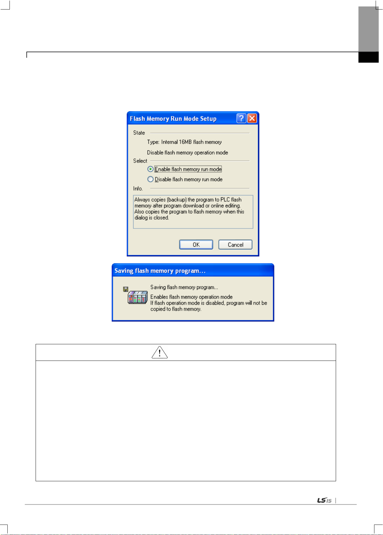
6-8
Caution
(1) The default is ‘Flash Memory Operation Mode deselected’.
set, the changed program may be applied only
writing, “Flash memory operation mode” is released.
Chapter 6 CPU Module Functions
(b) Flash Memory Operation Mode Setting
Check the operation mode setting by using ‘Online Set Flash Memory … ‘Enable flash memory run mode’
and click ‘OK. ’
Once pressing i t, it show s a dialogue box stati ng “Saving flash memory program …” and copies the program from
user program area to flash.
(2) Flash memory operation mode is maintained as ‘On’ as long as it is not ‘Off’ by XG5000.
(3) Flash memory operation mode can be changed, irrespective of RUN/STOP mode.
(4) Flash mem ory operation mode can be s et by the onli ne menu of XG 5000 when exec uting flash ‘operation
mode setting’ after program debugging is complete with the flash memory operation mode off.
(5) If modifying during RUN with ‘flash memory o perat ion m ode ’
when it restar ts as lo ng as the pr ogram is success full y writte n in flash memor y. Note tha t if the PL C restar ts
before a pr ogram is save d into flash m emory, a pr ogram that is s aved in adva nce, instead of the chang ed
program, works.
(6) If flash memory operation mode is changed from ‘disabled’ to ‘enable’, flash memory operation mode is
applied as long as the flash memory writing is com pl et e . In cas e the PL C r estarts before completing program

6-9
setting
CPU understands that flash memory does not have any
Chapter 6 CPU Module Functions
(c) Flash memory operation method
If restarting the PLC system or changing its operation mode to RUN , it works as follows depending o n the flash
operation mode setting.
Flash memory operation mode
On
Description
If program memory dat a are dam aged beca use flash mem ory
and program memor y are different or battery voltage is low, it
downloads the program saved in flash memory to program
memory.
Off
program and operates by the program saved in RAM.

6-10
Caution
Chapter 6 CPU Module Functions
6.4 Forced On/Off Function of I/O
The forcible I/O function is used to forcibly turn on or off I/O area, irrespective of program execution results.
6.4.1 Force I/O Setting
(1) Click [Online]-[Force I/O] on XG5000.
(a) To set forcible I/ O, select the flag of a conta ct to set and the data checkbox
(b) To set “1”, select the flag and data of a bit and then, select a flag.
(c) To set “0”, select a flag only , not the data corres pondin g to the bit .
(d) If selecting ‘forcibl e i npu t o r outp ut en able d’, the setting i s app lied a nd it works accordingly.
For further directions, please refer to the us e r’s manual of XG5000.
(1) Forcible I/ O s etti ng is available only in local I/O module .
(2) It can not be set in remote I/O module(smart I/O module).
(3) If for cible I/ O is set, “CHK LED” is On.
(4) The forcible I/ O set by a user is maint aine d even t houg h a n ew p ro gra m i s downloa ded .

6-11
Caution
Cautions for using forcible I/O
Chapter 6 CPU Module Functions
6.4.2 The point of time of method of forced On/Off process
(1) Forcible i npu t
‘Input’ replaces the data of a contact set by Forcible On/Off from the data read from input module at the time of input
refresh with the forcibly set data and updates input image area. Therefore, a user program can execute operation with
actual input data and forcibly set data.
(2) Forcible o ut put
‘Output’ replaces the data of a contact set by Forcible On /Off from th e outpu t image area dat a cont aining ope rati on
result at the time of output refresh with the forcibly set data and outputs to an output module after completing user
program operation. Unlike input, the data in output i mage a rea i s not c han ged by forcible On/Off set ting .
(1) It works from t he ti me w he n i npu t/out pu t a r e s et to ‘enable/disable’ respectively after setting forcible data.
(2) Forcible input can be set even thoug h a c tual I/O modul e i s n ot in s tall ed.
(3) The previously set On/Off setting data are kept in the CPU module, despite of power off on, operation
mode change, program download or manipulation by reset key. Howeve r, it i s del ete d i f ov er all re set is
executed.
(4) Forcible I/O da ta a re no t d ele ted eve n i n STOP mode.
(5) To set new data from the first, release every setting of I/O by using ‘overall reset’.

6-12
Note
Chapter 6 CPU Module Functions
6.5 Operation history saving function
There are four types of operation logs; Error log, Mode change log, shut down log and System log.
It saves the time, frequency and operation of each event into memory and a user can conveniently monitor them through
XG5000. Operation log is saved within the P LC un le s s it is del ete d by XG5000.
6.5.1 Error history
It saves error log that occurs during operation.
(1) Saving error code , date, time and erro r detail s.
(2) Saving logs up to 2,048
(3) Automatically released if memory backup is failed due to low battery level and etc
6.5.2 Mode change history
It saves the change mode information and time if an operation mode is changed.
(1) Saving the date, time and mode chan ge in formatio n.
(2) Saving up to 1 ,024.
6.5.3 Shut down history
Saving power On/ O ff da ta w ith i t’s time data.
(1) Saving On/Off data, date and time.
(2) Saving up to 1 ,024.
(3) History of master and standby power is indicated respectively.
6.5.4 System history
It saves the ope rati on log o f system that occur s du ring ope r ati on.
(1) Saving the date, time and operation changes
(2) XG5000 operation data, key swit ch change in formati on
(3) Instantaneous interruption data and network ope ration
(4) Saving up to 2 ,048
(1) The saved d at a a r e n ot deleted before it i s del et ed by sel ecti ng a menu in XG5 000.
(2) If executing Read All in case logs are more than 100, the previous logs are displayed.

6-13
Chapter 6 CPU Module Functions
6.6 External device failure diagnosis function
It is the flag that a user detects a fault o f external devi ce so that the su spension/w arni ng of a system coul d be easily re alized.
If using the flag, it can display a fault of external device, instead of creating a complex program and monitor a fault position
without XG5000 and source program.
(1) Detection/classification of external device fault
(a) The fault of external device is detected by a user progra m and it can be div ided into heavy fault(er ror) tha t require s
stopping the P LC o pe ra tion a nd l igh t fa ult (wa rning ) th at only di spl ay s faul t stat u s while it keeps operating.
(b) Heavy fault uses ‘_ANC_ERR' flag and light fault uses ‘_ANC_WB' flag.
(2) If a heavy fault of external device is detected
(a) If a heavy fault of external device is detected in a user program, it writes the val u e ac cording to error type defined in a
system fla g, ‘_ANC_ERR’ by a user. Then, with _CHK_ANC_ERR flag On, it check s at the complet ion of a scan
program. At the moment, if a fault is displayed, it is displayed in ‘_ANNUN_ER’ of ‘_CNF_ER’, which is the
represent ative error flag. Then, the PLC turns off every output module(depending on the output control setting of
basic param eter) and it has the same er ror status with PLC fa ult de tect ion. At th e m om ent , P.S LED and CHK LED
are On, besides ERR LED.
In case of a fault, a user can check the cause by using XG5000 and alternatively, check it by monitoring ‘_ANC_ERR’
(b)
flag.
(c) To turn off ERR LED, P.S LED and CHK LED, which are On by heavy fault error flag o f e xte rnal dev i ce, it i s nece ssa ry
to reset the PLC o r t urn i t o ff a nd on ag ai n .
Example
(3) If a li ght faul t o f e xte rna l devi c e i s d ete cte d
(a) If a lig h t fa u lt of ex t ernal device is det ected in a user program, it writes the val u e according to warning type defined in
‘_ANC_WAR’ by a us er. Then, with _CHK_ANC_WAR On, it c hecks at th e completio n of a scan program. At the
moment, if a warning is displayed, ‘_ANNUN_WAR’ of ‘_CNF_WAR’, which is the representative error flag of system
is On. At the moment, P.S LED and CHK LED are On.
(b) If a war ning occurs, a user can ch eck the ca uses b y using XG 5000. Alternatively, a user can check the causes by
directly monitoring ‘_ANC_WAR’ flag.
(c) With _CHK_ANC_WAR OFF, P. S LED and CHK LED are of f and the displa y,
reset.
Example
‘_ANNUN_WAR’ of ‘_CNF_WAR’ is

6-14
Chapter 6 CPU Module Functions
6.7 Redundancy system operation setting
For redundant syste m operat ion, redu ndan cy paramete rs have to be s et up.
Redundanct paramete r config urat ionis cla ssi fied into the operati on mode se tting and data sync hroniz ation area setting.
The default setting has no data synchronization area. Be careful that, if the data synchroniz atio n area is not se t up, the
data of the master CPU is not synchronized to the standby CPU.
Different from other parameters, the dredundancy parameters can be written during running.
However, the redundan cy para met e rs canno t be au tomati cal ly dpw nloa ded d u ring running w ri tin g.
From the XG5000 online writin g, sele ct the r edu nda n cy par a meter s only and download t he m.
6.7.1 Operation mode setting
(1) Single CPU operation mode
If the system is operati on with master CPU only , withou t standby , redundancy system configuration warning occurs.
To configure XGR system with a single CPU, select the ‘Di sabl e the wa rni ng messa ge fo r Si ngle C PU Mode’ check box
to prevent the warning display.

6-15
Caution
Chapter 6 CPU Module Functions
It is recommended to configure the XGR system in redundant CPU system. If the redundant system is configured
with single CPU , the s ystem stops if the CPU m odu le fai ls. To preve nt s ystem interr upti on, s et up the s ystem in
redundant CPU configuration
(2) Error handling in power cut-off of expansion base
In a redundant XGR system configured wuth multiple extensin bases for enhanced system reliability and diver sity, in case
of detach (powr off) of expansion base(s), the user can select whether to consider it as error or CPU restarts the system
and watis until exension base in problem paricipate in operation again.
a) If the check box “Restart and wait” is selected;
As the default setting , in case of a problem in an expansion base, the system is restarted and the CPU module waits
until the bas e i n fail u re is normalized. The base in failure is indicated wi th “Ebx x” in the CPU indi cator panel .
When the failed base is restarted normally and returns to the system, the CPU module restarts in the same manner as
the initial start-up and carry out normal operation.
b) If the check box “Extended Base Detach Error ” is selected;
In case of failure of an expansion base, other modules operate in accordance with the error process setting in the basic
parameter settings.
If the basic parameter was set to maintain output under error occurrence, other modules maintain the last output.

6-16
Caution
Chapter 6 CPU Module Functions
6.7.2 Data synchronization area setting
(1) M area setting
Setting can be made by 1 kbyte step within 1 ~ 256 kByte range.
Initial value: %MW0~%MW2000
Change in Start End method
(2) I/Q : setting by base unit
Setting can be made in base unit.
Initial value i s 31 bases (error message if the setting value is less than the number of installed bases)
(3) PID : setting by block (max. 8 blocks)
For the synchronization area of the PID area, 32 PID areas are allocated for each block
- Initial value: 0 block
(4) R(W) : set R only, and automatic setting for W
Synchronization area for R(W) area
- Initial value : %RW0~%RW2000(%WW0~%WW2000, %WW32768~%WW34768)
(1) The M area retain can be set up in the “Basic Parameter Setting.” For details, see “5.5.3 Data Retain Area
Setting.”
(2) When the master/standby CPUs are performing redundant operati on, follow ing s are automati cally
synchronized.
(a) L (high speed link fla g), N(P2P paramete r settin g) devi ce area
(b) F (system flag area) device area (howev er, indiv idual flag are as are not sy nchroniz ed) .
(c) U (special module refresh area) device area (however, only installed modules are synchronized).
(3) If a variable value has been changed during monitoring by XG5000, it applies to the respective areas of the
master and standby CPUs, rega rdles s of the data sync hroniz ation area setting.
 Loading...