


Right choice for ultimate yield
LSIS strives to maximize customers' profit in gratitude of choosing us for your partner.
Programmable Logic Controller
RAPIEnet I/F Module
User’s Manual
Read this manual carefully before
installing, wiring, operating, servicing
or inspecting this equipment.
Keep this manual within easy reach
for quick reference.
XGL-EIMT
XGL-EIMF
XGL-EIMH
XOL -EIMT
XOL -EIMF
XBL -EIMT
XGT Series
http://eng.lsis.biz
Safety Instructions
Warning
Caution
Before using the product …
For your safety and effective operation, please read the safety instructions
thoroughly before using the product.
► Safety Instructions should always be observed in order to prevent accident
or risk with the safe and proper use the product.
► Instructions are divided into “Warning” and “Caution”, and the meaning of
the terms is as follows.
This symbol indicates the possibility of serious injury
or death if some applicable instruction is violated
This symbol indicates the possibility of severe or
slight injury, and property damages if some
applicable instruction is violated
Moreover, even classified events under its caution category may develop into
serious accidents relying on situations. Therefore we strongly advise users to
observe all precautions properly just like warnings.
► The marks displayed on the product and in the user’s manual have the
following meanings.
Be careful! Danger may be expected.
Be careful! Electric shock may occur.
► The user’s manual even after read shall be kept available and accessible to
any user of the product.

Safety Instructions
Please install a protection circuit on the exterior of PLC so that the
whole system may operate safely regardless of failures from
external power or PLC. Any abnormal output or operation from PLC
may cause serious problems to safety in whole system.
- Install protection units on the exterior of PLC like an interlock circuit
that deals with opposite operations such as emergency stop,
protection circuit, and forward/reverse rotation or install an interlock
circuit that deals with high/low limit under its position controls.
- If any system error (watch-dog timer error, module installation error,
etc.) is detected during CPU operation in PLC, all output signals are
designed to be turned off and stopped for safety. However, there
are cases when output signals remain active due to device failures
in Relay and TR which can’t be detected. Thus, you are
recommended to install an addition circuit to monitor the output
status for those critical outputs which may cause significant
problems.
Never overload more than rated current of output module nor
allow to have a short circuit. Over current for a long period time may
cause a fire .
Never let the external power of the output circuit to be on earlier
than PLC power, which may cause accidents from abnormal output or
operation.
Please install interlock circuits in the sequence program for safe
operations in the system when exchange data with PLC or modify
operation modes using a computer or other external equipments
Read specific instructions thoroughly when conducting control
operations with PLC.
Warning
Safety Instructions for design process

Safety Instructions
I/O signal or communication line shall be wired at least 100mm
away from a high-voltage cable or power line. Fail to follow this
instruction may cause malfunctions from noise
Caution
Use PLC only in the environment specified in PLC manual or
general standard of data sheet. If not, electric shock, fire, abnormal
operation of the product may be caused.
Before install or remove the module, be sure PLC power is off. If
not, electric shock or damage on the product may be caused.
Be sure that every module is securely attached after adding a
module or an extension connector. If the product is installed
loosely or incorrectly, abnormal operation, error or dropping may be
caused. In addition, contact failures under poor cable installation will
be causing malfunctions as well.
Be sure that screws get tighten securely under vibrating
environments. Fail to do so will put the product under direct
vibrations which will cause electric shock, fire and abnormal
operation.
Do not come in contact with conducting parts in each module,
which may cause electric shock, malfunctions or abnormal operation.
Caution
Safety Instructions for design process
Safety Instructions on installation process
Safety Instructions
Prior to wiring works, make sure that every power is turned off. If
not, electric shock or damage on the product may be caused.
After wiring process is done, make sure that terminal covers are
installed properly before its use. Fail to install the cover may cause
electric shocks.
Warning
Check rated voltages and terminal arrangements in each product
prior to its wiring process. Applying incorrect voltages other than
rated voltages and misarrangement among terminals may cause fire
or malfunctions.
Secure terminal screws tightly applying with specified torque. If
the screws get loose, short circuit, fire or abnormal operation may be
caused. Securing screws too tightly will cause damages to the module
or malfunctions, short circuit, and dropping.
*
Be sure to earth to the ground using Class 3 wires for FG
terminals which is exclusively used for PLC. If the terminals not
grounded correctly, abnormal operation or electric shock may be
caused.
Don’t let any foreign materials such as wiring waste inside the
module while wiring, which may cause fire, damage on the product
or abnormal operation.
Make sure that pressed terminals get tighten following the
specified torque. External connector type shall be pressed or
soldered using proper equipments.
Caution
Safety Instructions for wiring process

Safety Instructions
Don’t touch the terminal when powered. Electric shock or abnormal
operation may occur.
Prior to cleaning or tightening the terminal screws, let all the
external power off including PLC power. If not, electric shock or
abnormal operation may occur.
Don’t let the battery recharged, disassembled, heated, short or
soldered. Heat, explosion or ignition may cause injuries or fire.
Warning
Do not make modifications or disassemble each module. Fire,
electric shock or abnormal operation may occur.
Prior to installing or disassembling the module, let all the
external power off including PLC power. If not, electric shock or
abnormal operation may occur.
Keep any wireless equipment such as walkie-talkie or cell phones
at least 30cm away from PLC. If not, abnormal operation may be
caused.
When making a modification on programs or using run to modify
functions under PLC operations, read and comprehend all
contents in the manual fully. Mismanagement will cause damages to
products and accidents.
Avoid any physical impact to the battery and prevent it from
dropping as well. Damages to battery may cause leakage from its
fluid. When battery was dropped or exposed under strong impact,
never reuse the battery again. Moreover skilled workers are needed
when exchanging batteries.
Caution
Safety Instructions for test-operation and
maintenance

Safety Instructions
Product or battery waste shall be processed as industrial waste.
The waste may discharge toxic materials or explode itself.
Caution
Safety Instructions for waste disposal

Version
Date
Details
Page
V 1.0
’08.01
First Edition
-
V 1.1
’10.03
1. Number of modules available by CPU types
(new model added)
2. Specification added
Ch1.3.2
Ch2.2
V 1.2
’10.09
XGB RAPIEnet added
-
V 1.3
’11.05
How to enable link through flag added
Ch 5.5.2
Revision History
Revision History
※ The number of User’s manual is indicated right part of the back cover.
Copyright ⓒ 2005 LSIS Co., Ltd All Rights Reserved.

1
Title
Description
XG5000 User’s Manual
XG5000 software user manual describing online function such as
programming, print, monitoring, debugging by using XGK, XGB
CPU
XG5000 User’s Manual
(for XGI, XGR)
XG5000 software user manual describing online function such
as programming, print, monitoring, debugging by using XGI,
XGR CPU
XGK/XGB Instructions & Programming
User’s Manual
User’s manual for programming to explain how to use
instructions that are used PLC system with XGK, XGB CPU.
XGI/XGR Instructions & Programming
User’s Manual
User’s manual for programming to explain how to use
instructions that are used PLC system with XGI, XGR CPU.
XGK CPU User’s Manual
(XGK-CPUA/CPUE/CPUH/CPUS/CPUU)
XGK-CPUA/CPUE/CPUH/CPUS/CPUU user manual describing
about XGK CPU module, power module, base, IO module,
specification of extension cable and system configuration, EMC
standard
XGI CPU User’s Manual
(XGI-CPUU)
XGI-CPUU user manual describing about XGK CPU module,
power module, base, IO module, specification of extension cable
and system configuration, EMC standard
XGR redundant series User’s
Manual
XGR-CPUU user manual describing about XGR CPU module,
power module, extension drive, base, IO module, specification of
extension cable and system configuration, EMC standard
About User’s Manual
Thank you for purchasing PLC of LSIS Co.,Ltd.
Before use, make sure to carefully read and understand the User’s Manual about the functions, performances, installation and
programming of the product you purchased in order for correct use and importantly, let the end user and maintenance
administrator to be provided with the User’s Manual.
The User’s Manual describes the product. If necessary, you may refer to the following description and order accordingly. In
addition, you may connect our website (http://eng.lsis.biz/) and download the information as a PDF file.
Relevant User’s Manuals

1
◎ Contents ◎
Chapter 1 Introduction
Chapter 2 Product Specifications
Chapter 3 Installation and Test Operation
Chapter 4 System Configuration
Contents
1.1 Introduction ----------------------------------------------------------------------------------------------------------------------------------------------- 1-1
1.2 Features --------------------------------------------------------------------------------------------------------------------------------------------------- 1-2
1.3 Product Configuration -------------------------------------------------------------------------------------------------------------------------------- 1-3
1.3.1 Type ------------------------------------------------------------------------------------------------------------------------------------------- 1-3
1.3.2 Number of modules available by CPU types -------------------------------------------------------------------------------------- 1-3
1.4 Software for Product ---------------------------------------------------------------------------------------------------------------------------------- 1-4
1.4.1 Check point for Software ---------------------------------------------------------------------------------------------------------------- 1-4
1.4.2 XG-PD ---------------------------------------------------------------------------------------------------------------------------------------- 1-4
1.4.3 Version information ----------------------------------------------------------------------------------------------------------------------- 1-5
2.1 General Specifications -------------------------------------------------------------------------------------------------------------------------------- 2-1
2.2 Performance Specifications ------------------------------------------------------------------------------------------------------------------------- 2-3
2.2.1 Expectation of Communication Load ------------------------------------------------------------------------------------------------ 2-5
2.3 Structure and Characteristics ----------------------------------------------------------------------------------------------------------------------- 2-7
2.4 Cable Specifications ----------------------------------------------------------------------------------------------------------------------------------- 2-9
2.4.1 Expectation of Communication Load ------------------------------------------------------------------------------------------------ 2-9
2.4.2 Optical cable ------------------------------------------------------------------------------------------------------------------------------- 2-11
3.1 Installation Environment ------------------------------------------------------------------------------------------------------------------------------ 3-1
3.2 Precaution for Handling ------------------------------------------------------------------------------------------------------------------------------ 3-6
3.3 Sequence from installation to operation --------------------------------------------------------------------------------------------------------- 3-7
3.3.1 RAPIEnet I/F Module for PLC ----------------------------------------------------------------------------------------------------------- 3-7
3.3.2 RAPIEnet I/F module for PC ------------------------------------------------------------------------------------------------------------- 3-8
3.4 Parameter setting in the XG-PD ------------------------------------------------------------------------------------------------------------------- 3-9
3.4.1 Parameter setting --------------------------------------------------------------------------------------------------------------------------- 3-9
3.5 I/O Allocation and Device Information ---------------------------------------------------------------------------------------------------------- 3-10
3.5.1 I/O allocation -------------------------------------------------------------------------------------------------------------------------------- 3-10
3.6 Installation ---------------------------------------------------------------------------------------------------------------------------------------------- 3-15
3.6.1 Installation of XGL-EIMT and XOL-EIMT ------------------------------------------------------------------------------------------ 3-15
3.6.2 Installation of XGL-EIMF and XOL-EIMF ----------------------------------------------------------------------------------------- 3-17
3.6.3 Installation of XGL-EIMH -------------------------------------------------------------------------------------------------------------- 3-18
3.7 Test Operation ---------------------------------------------------------------------------------------------------------------------------------------- 3-19
3.7.1 Precautions for system configuration ------------------------------------------------------------------------------------------------ 3-19
4.1 Available System Configuration-------------------------------------------------------------------------------------------------------------------- 4-1
4.1.1 Ring type system with electric module ------------------------------------------------------------------------------------------------ 4-1
4.1.2 Ring type system with optical module ------------------------------------------------------------------------------------------------ 4-3
4.1.3 Ring type system with combined module -------------------------------------------------------------------------------------------- 4-4
4.1.4 Line type system with optical module ------------------------------------------------------------------------------------------------- 4-5

2
Chapter 5 Communication Parameters
Chapter 6 High-speed Link
Chapter 7 P2P Service
Contents
5.1 Introduction --------------------------------------------------------------------------------------------------------------------------------------------- 5-1
5.1.1 High-speed link setting parameters ----------------------------------------------------------------------------------------------------- 5-1
5.1.2 P2P Setting Parameters ----------------------------------------------------------------------------------------------------------------- 5-2
5.1.3 Comparison between high speed link and P2P ------------------------------------------------------------------------------------- 5-3
5.2 Installation and Execution of Software -------------------------------------------------------------------------------------------------------- 5-4
5.2.1 Installation of XG5000 -------------------------------------------------------------------------------------------------------------------- 5-4
5.2.2 Installation of USB device driver ------------------------------------------------------------------------------------------------------- 5-7
5.2.3 Confirmation of installed USB device drive ------------------------------------------------------------------------------------------ 5-11
5.3 Registration of Communication Module ------------------------------------------------------------------------------------------------------ 5-18
5.3.1 Off-line registration ------------------------------------------------------------------------------------------------------------------------ 5-18
5.3.2 On-line registration ------------------------------------------------------------------------------------------------------------------------ 5-19
5.3.3 How to read the parameter saved in the PLC ------------------------------------------------------------------------------------- 5-20
5.3.4 Module setting method ------------------------------------------------------------------------------------------------------------------- 5-21
5.3.5 Menu bar and shortcut of XG-PD ----------------------------------------------------------------------------------------------------- 5-22
5.4 How to set the parameter according to service -------------------------------------------------------------------------------------------- 5-23
5.4.1 High-speed link service ------------------------------------------------------------------------------------------------------------------ 5-23
5.4.2 P2P Service ------------------------------------------------------------------------------------------------------------------------------- 5-26
5.5 Operation Start-up ---------------------------------------------------------------------------------------------------------------------------------- 5-27
5.5.1 XG-PD setting ------------------------------------------------------------------------------------------------------------------------------ 5-27
5.5.2 When operating in high speed link service ----------------------------------------------------------------------------------------- 5-28
5.5.3 Operating in P2P service ---------------------------------------------------------------------------------------------------------------- 5-34
6.1 Introduction --------------------------------------------------------------------------------------------------------------------------------------------- 6-1
6.2 HS link Tx/Rx Data Processing ------------------------------------------------------------------------------------------------------------------- 6-2
6.3 Operation Sequence through High-speed Link ---------------------------------------------------------------------------------------------- 6-3
6.4 HS link parameters setting ------------------------------------------------------------------------------------------------------------------------- 6-4
6.4.1 HS link parameters setting of XG-PD -------------------------------------------------------------------------------------------------- 6-4
6.5 High-speed link information ------------------------------------------------------------------------------------------------------------------------ 6-9
6.5.1 High-speed link flag ------------------------------------------------------------------------------------------------------------------------- 6-9
6.5.2 Monitor of High-speed link information ------------------------------------------------------------------------------------------------ 6-11
7.1 Introduction --------------------------------------------------------------------------------------------------------------------------------------------- 7-1
7.2 P2P Instruction ---------------------------------------------------------------------------------------------------------------------------------------- 7-1
7.3 P2P Application --------------------------------------------------------------------------------------------------------------------------------------- 7-2
7.3.1 Functions and setting of P2P ----------------------------------------------------------------------------------------------------------- 7-4
7.4 Operation Sequence of P2P Service ----------------------------------------------------------------------------------------------------------- 7-6
7.5 P2P Service Information ---------------------------------------------------------------------------------------------------------------------------- 7-7
7.5.1 P2P service from the XG-PD system diagnosis ----------------------------------------------------------------------------------- 7-7

3
Chapter 8 Remote Connection Service
Chapter 9 Example Program
Chapter 10 Diagnostic Function
Appendix
Contents
8.1 Introduction ------------------------------------------------------------------------------------------------------------------------------------------- 8-1
8.2 Setting and Connection --------------------------------------------------------------------------------------------------------------------------- 8-2
8.2.1 Remote 1 connection --------------------------------------------------------------------------------------------------------------------- 8-2
8.2.2 Remote 2 connection --------------------------------------------------------------------------------------------------------------------- 8-5
9.1 High Speed Link Program ---------------------------------------------------------------------------------------------------------------------- 9-1
9.1.1 High Speed Link parameter setting ------------------------------------------------------------------------------------------------ 9-1
9.1.2 How to set HS link speed ------------------------------------------------------------------------------------------------------------ 9-4
9.1.3 High Speed Link Diagnosis service ----------------------------------------------------------------------------------------------- 9-5
9.2 P2P Program -------------------------------------------------------------------------------------------------------------------------------------- 9-6
9.2.1 P2P parameter setting ---------------------------------------------------------------------------------------------------------------- 9-6
9.2.2 P2P Diagnosis ------------------------------------------------------------------------------------------------------------------------ 9-10
10.1 System diagnosis ------------------------------------------------------------------------------------------------------------------------------ 10-1
10.2 Communication module information ----------------------------------------------------------------------------------------------------- 10-2
10.3 Auto Scan ---------------------------------------------------------------------------------------------------------------------------------------- 10-3
10.3.1 Auto scan ------------------------------------------------------------------------------------------------------------------------------ 10-3
10.3.2 Cable distance measurement ------------------------------------------------------------------------------------------------- 10-4
10.3.3 Diagnosis on the status information of remote modules ----------------------------------------------------------------- 10-4
10.4 Media information diagnosis ---------------------------------------------------------------------------------------------------------------- 10-8
10.4.1 Media information ------------------------------------------------------------------------------------------------------------------- 10-8
10.4.2 View error details -------------------------------------------------------------------------------------------------------------------- 10-9
10.5 Troubleshooting ------------------------------------------------------------------------------------------------------------------------------- 10-10
10.5.1 Diagnosis through communication Module LED -------------------------------------------------------------------------- 10-10
10.5.2 Diagnosis of Communication Module through XG5000 --------------------------------------------------------------- 10-11
10.5.3 Checking module healthiness with system log ---------------------------------------------------------------------------- 10-11
A.1 Terminology ---------------------------------------------------------------------------------------------------------------------------------------- A-1
A.2 List of Flags -------------------------------------------------------------------------------------------------------------------------------------- A-3
A.2.1 List of Special Relays (F) ----------------------------------------------------------------------------------------------------------- A-3
A.2.2 List of Communication Relays (L) --------------------------------------------------------------------------------------------- A-11
A.2.3 List of Link device (N) ------------------------------------------------------------------------------------------------------------- A-14
A.3 Dimension ---------------------------------------------------------------------------------------------------------------------------------------- A-17
A.4 Troubleshooting -------------------------------------------------------------------------------------------------------------------------------- A-20
A.4.1 Hardware failure --------------------------------------------------------------------------------------------------------------------- A-20
A.4.2 Interface failure ----------------------------------------------------------------------------------------------------------------------- A-21
A.4.3 CPU and interface failure during operation --------------------------------------------------------------------------------- A-22
A.4.4 High-speed link parameter error ------------------------------------------------------------------------------------------------- A-23
A.4.5 High-speed link operation failure ------------------------------------------------------------------------------------------------ A-24
A.5 Performance Table --------------------------------------------------------------------------------------------------------------------------- A-25
A.5.1 High-speed link performance table ---------------------------------------------------------------------------------------------- A-25
A.6 Error Code --------------------------------------------------------------------------------------------------------------------------------------- A-26
A.6.1 P2P client error code ---------------------------------------------------------------------------------------------------------------- A-26

1-1
1.1 Introduction
Chapter 1 Introduction
Chapter 1 Introduction
This User Manual describes the Ethernet RAPIEnet I/F module (hereinafter, RAPIEnet I/F Module) for the exclusive use on
dual port in the XGT PLC system network. The RAPIEnet I/F Module carries out the communication between the PLCs in the
XGT series on the basis of Ethernet communication, and provides two Ethernet ports which can be configured in line (daisy
chain) and ring structure, enabling construction of network which is more flexible than conventional star-type PLC communication
module. The RAPIEnet I/F Module can be classified into 2 electrical ports (10/100BASE-TX), 2 optical ports (100BASE-FX), and
hybrid (10/100BASE-TX, 100BASE-FX) according to the media type. The Module is an interface module for data transmission
between PLCs using these ports.
To create a program, refer to the following manuals together.
XG5000 user manual
XGK instruction
XGK user manual
XGI/XGR instruction
XGI/XGR user manual
When configuring communication module system, pay attention to each program and module version.
1) When configuring a XGT RAPIEnet I/F module system
XGT PLC XG5000 (Programming Tool): V2.0 or above
XG-PD: V2.0 or above
XGK CPU series: V2.0 or above
XGI CPU series: V2.0 or above
XGR CPU series: V1.0 or above
2) When configuring a XGB RAPIEnet I/F module system
XGT PLC XG5000 (Programming Tool): V3.3 or above
XG-PD: V3.3 or above
XBC high-end type CPU series: V2.0 or above

1-2
1.2 Features
Chapter 1 Introduction
The XGT RAPIEnet I/F Nodule has following features.
(1) Supports IEEE 802.3 Standard.
(2) Supports high speed link between RAPIEnet modules for high speed data communication.
(Max. 64 blocks for transmission, max. 128 blocks for reception, min. 5ms of high speed link cycle)
(3) Provides 100BASE-TX and 100BASE-FX media, and supports full duplex of 100Mbps.
(4) Supports Dynamic Connection/Disconnection using P2P service.
(5) Suitable for large volume data exchange. (Max. high speed link communication rate: 25,600* 12 = 307,200 words)
(6) Max. 24 modules can be installed per CPU module, available for both principal and extended bases. However, in
the XGR system, the module can be installed on the principal base only. The I/F card for PC can be installed 1 per
1 PC.
(7) Supports ring and line (daisy chain) topology to enable construction of networks most suitable for on-site use. Ring
topology structure supports redundancy function.
(8) Optical, electrical, and hybrid modules are provided for various control networks, overcoming the limitation in
distance.
(Built-in switching function enables construction of ring and line topology without additional switch or hub, with reduced
wiring and improved flexibility in installation.)
(9) Provides alarm function for station number conflict.
(10) Auto Cross-Over function is provided for convenient cable work.
(11) Cable distance measuring function is provided for the use of electrical cable
(12) Network-based simultaneous OS upgrade
(13) Various diagnoses functions are provided. The status information of modules and network is provided.
(a) CPU module status
(b) Communication module status
(c) Communication service (high-speed link, exclusive service, P2P) status
(d) Auto Scan function provides the information on the modules belong to the company connected in the network
(e) Provides information on the type and data volume of packet received through communication module, which
enables network load prediction.
(f) Diagnosis of communication modules through network
(14) Module can be set up simply with station number, without IP
1-3
1.3 Product Configuration
Type
Description
Remarks
XGK/I/R
XGL-EIMT
Electric 2 ports
Category 5 or above
XGL-EIMF
Optical 2 ports
XGL-EIMH
Electric 1 port, optical 1port
XGB
XBL-EIMT
Electric 2 ports
Option
XOL-EIMT
Electric 2 ports
Multi-mode optical cable of two wires
XOL-EIMF
Optical 2 ports
Classification
XGK
XGI
XGR
note1)
XGB
PC I/F
Card
CPUH
CPUH
CPUA
CPUS
CPUE
CPUU
CPUH
CPUS
CPUE
CPUH/F
CPUH/T
XBC
Max. number of
modules using high
speed link
12
note2)
2
1
Max. number of
modules using P2P
8
note2)
2
-
Max. number of
module (including
the modules using
exclusive services)
24
note2)
2
1
Note
Note1) Installation position of RAPIEnet I/F module according to CPU type
- When using XGK/XGI CPU, you can install the RAPIEnet I/F module at main both base and expansion base.
- When using XGR CPU, you can install the RPIEnet I/F module at main base only.
Note2) The number of XGR’s module using P2P
- For RAPIEnet, it can be installed at main base so the number of module using High speed link and P2P is up to 6.
1.3.1 Type
It describes product spec. of XGT RAPIEnet I/F module.
Chapter 1 Introduction
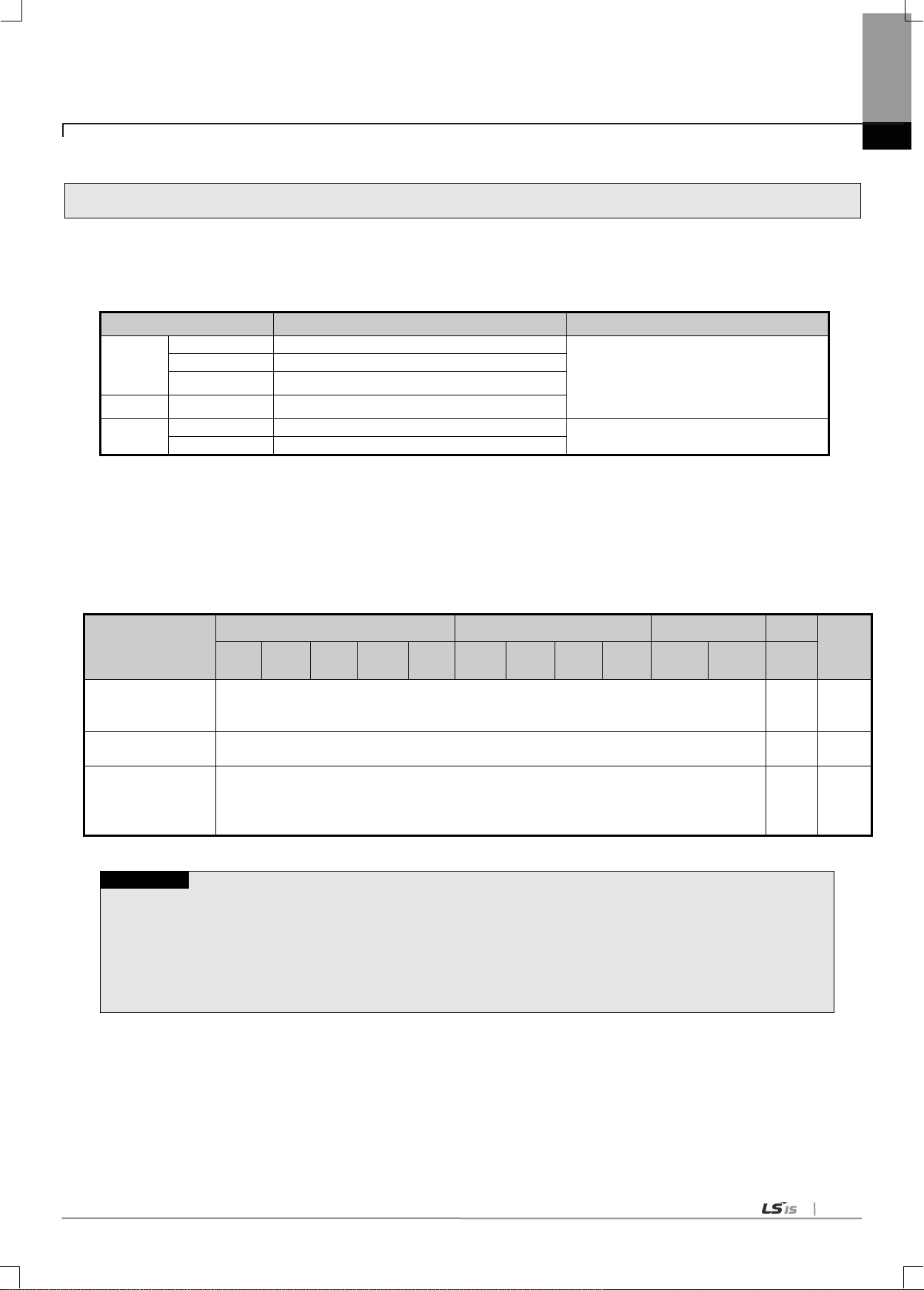
1.3.2 Number of modules available by CPU types
RAPIEnet I/F Modules can be installed up to 24 sets regardless of main or extension bases. It is recommended to
install the modules on the main base for maximum usability. The table below shows the types of services available
for each CPU. You can use this table for system construction considering the number of communication modules.
Note 1) The RAPIEnet I/F Module can be installed on the main base only when using XGR CPU.

1-4
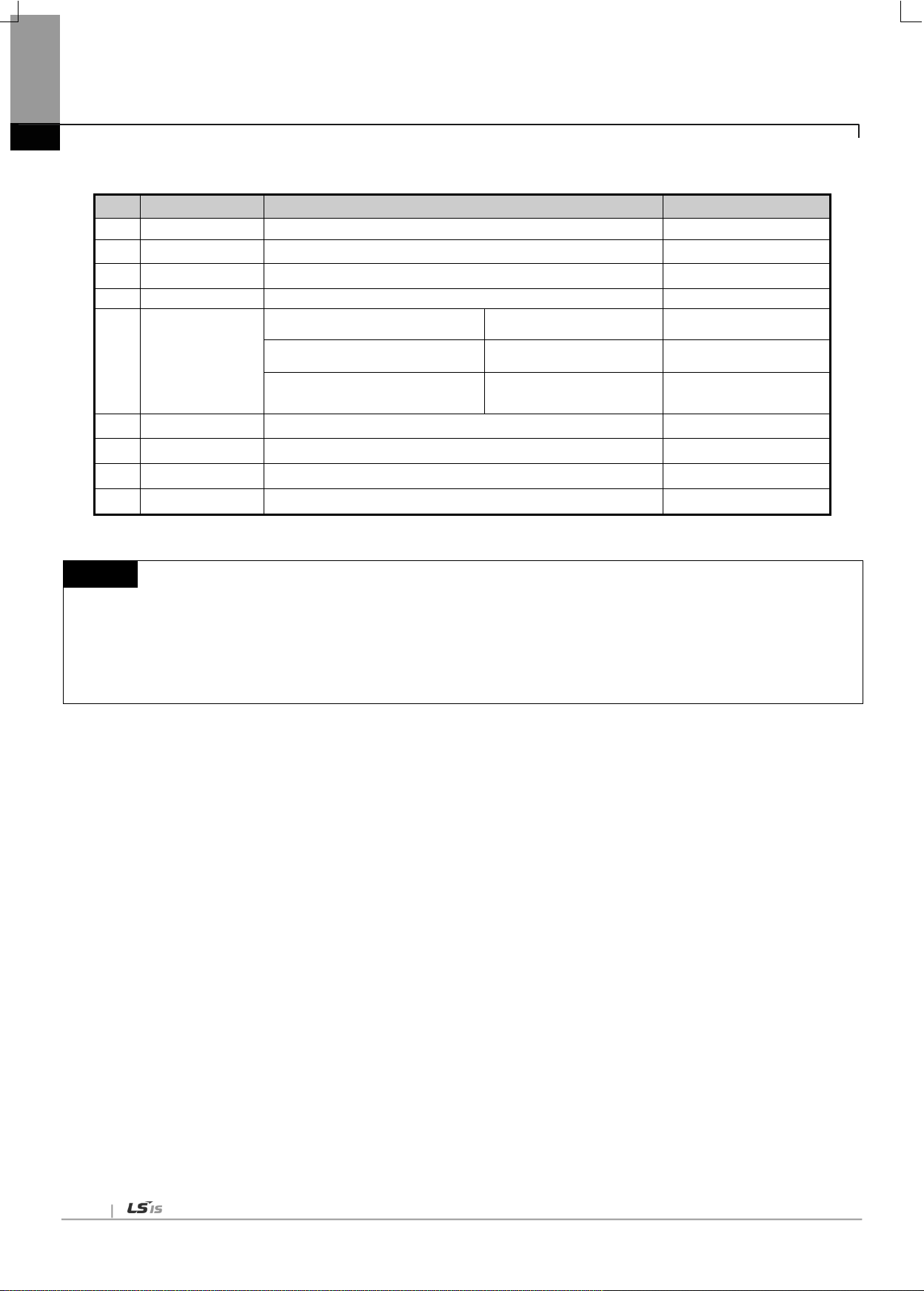
1.4 Software for Product
Category
Item
Communication setting
XGL-EIMT
Comm. Module for XGT
XG-PD
XGL-EIMF
XGL-EIMH
XBL-EIMT
XOL-EIMT
PCI interface hardware
Device driver (*.DLL)
User application
(Visual basic, Visual C etc.)
XOL-EIMF
Note
1) The above program is downloadable form the website below. If Internet is not available, it is also possible to
use it from Installation CD-ROM by visiting the close agency.
Internet Website: http://www.lsis.biz
2) XG5000 and XG-PD are programmable through RS-232C port of CPU module and USB. For the cable type,
refer to XGT Catalog Product Exhibit(USB-301A, K1C-050A).
Chapter 1 Introduction
It describes major programming tool and other developer’s software for using XGT RAPIEnet I/F module. For
more accurate application of program and communication, it is useful to refer to the follows before applying to the
system.
1.4.1 Check point for Software
1.4.2 XG-PD
XG-PD is the dedicated communication software supporting basic parameter setting, frame creation and diagnostics of
module and network for the operation of all communication modules including RAPIEnet I/F module.
The following figure shows the initial window when starting XG-PD.
[Fig. 1. 4.1] XG-PD Initial Window

1-5
1.4.3 Version information
Before using RAPIE I/F module, check the version of module.
(1) Check by XG-PD
It directly connects communication module online to read the info of communication module. During normal interface with
CPU, it can show the following information.
(a) Run XG-PD.
(b) With online connection, connect to CPU.
(c) If connected to CPU, it executes System Diagnosis of XG-PD.
(d) In the system diagnosis window from the online menu, place the mouse pointer on the pertinent communication
module.
(e) Double-click the communication module, or right-click the mouse button. Select detail information of the
communication module.
Chapter 1 Introduction
[Fig. 1.4.2] Checking module’s version by XG-PD
(2) Check by product’s case label
Each communication module is with module’s product info on its external case.
If online check is not possible due to absence of any external device interfacing with a PC, it can be checked after detaching
a module.
The rear side has product label showing the product’s type and version.

2-1
2.1 General Specifications
No.
Items
Specifications
Related standards
1
Operating
temperature
0 ~ 55 C
2
Storage
temperature
25 ~ 70 C
3
Operating
humidity
5 ~ 95%RH (Non-condensing)
4
Storage
humidity
5 ~ 95%RH (Non-condensing)
5
Vibration
resistance
Occasional vibration
-
Frequency
Acceleration
Amplitude
times
IEC61131-2
10 f 57Hz
0.075mm
10 times each
directions
(X, Y and Z)
57 f 150Hz
9.8m/s2(1G)
Continuous vibration
Frequency
Acceleration
Amplitude
10 f 57Hz
0.035mm
57 f 150Hz
4.9m/s2(0.5G)
6
Shock
resistance
Peak acceleration: 147 m/s2(15G)
Duration: 11ms
Half-sine, 3 times each direction per each axis
IEC61131-2
7
Noise
resistance
Square wave
Impulse noise
1,500 V
LSIS standard
Electrostatic
discharge
4kV (Contact discharge)
IEC61131-2
IEC61000-4-2
Radiated
electromagnetic
field noise
80 ~ 1,000 MHz, 10V/m
IEC61131-2,
IEC61000-4-3
Fast
transient/bust
noise
Segm
ent
Power supply
module
Digital/analog input/output
communication interface
IEC61131-2
IEC61000-4-4
Voltage
2kV
1kV
8
Environment
Free from corrosive gasses and excessive dust
9
Altitude
Up to 2,000 ms
10
Pollution
degree
2 or less
11
Cooling
Air-cooling
N0ote
1) IEC (International Electrotechnical Commission):
An international nongovernmental organization which promotes internationally cooperated standardization in
electric/electronic field, publishes international standards and manages applicable estimation system related with.
2) Pollution degree:
An index indicating pollution degree of the operating environment which decides insulation performance of the devices. For
instance, Pollution degree 2 indicates the state generally that only non-conductive pollution occurs. However, this state contains
temporary conduction due to dew produced.
Chapter 2 Product Specifications
General specifications of XGT series are as shown below.
Chapter 2 Product Specifications
[Table 2.1.1] General specification for PLC
2-2
No.
Items
Specification
Reference
1
Ambient Temp.
0℃∼+55℃
2
Storage Temp.
-25℃∼+70℃
3
Ambient humidity
5∼95%RH, (Non-condensing)
4
Storage humidity
5∼95%RH, (Non-condensing)
5
Noise Immunity
Square wave impulse noise
±1,500V
LSIS internal test spec.
Electrostatic discharge
Voltage : 4kV
(Contact discharge)
IEC 61131-2,
IEC 61000-4-2
Radiated electromagnetic field noise
27 ~ 500MHz, 10 V/m
IEC 61131-2,
IEC 61000-4-3
6
Operation ambience
Free from corrosive gases and excessive dust
7
Altitude
Less than 2,000m
8
Pollution degree
Less than 2
9 Cooling method
Air-cooling
N0ote
1) IEC (International Electrotechnical Commission):
An international nongovernmental organization which promotes internationally cooperated standardization in
electric/electronic field, publishes international standards and manages applicable estimation system related with.
2) Pollution degree:
An index indicating pollution degree of the operating environment which decides insulation performance of the devices. For
instance, Pollution degree 2 indicates the state generally that only non-conductive pollution occurs. However, this state contains
temporary conduction due to dew produced.
Chapter 2 Product Specifications
General specifications of PC I.F card are as shown below.
[Table2.1.2]General specification for PC I/F card

2-3
2.2 Performance Specifications
Item
XGK/I/R
XGB
100BASE-FX
100BASE-TX
100BASE-TX
Transmission
Specification
Baud rate
100Mbps
100Mbps
100Mbps
Transmission Type
Base band
Max. extended length between nodes
2km
100m
100m
Max. number of nodes
64
Max. protocol size
1,516 byte
Access method to service zone
CSMA/CD
Frame error check
CRC 32 = X
32
+ X26 + X23+ ,,,,, + X2 + X + 1
Max.
equipment no.
note1)
PLC
12
2
PC 1 -
Equip-able
location
PLC
XGK-CPUU/H,
XGI-CPUU
Main base ~ extension step 7
-
-
XGK-CPUE
Main base ~ extension step 1
-
XGK-CPUA/S,
XGI-CPUH/S
Main base ~ extension step 3
-
XGR-CPUH/F,
XGR-CPUH/T
Main base
-
XBC
-
Main base
extension
PC
Empty PCI slot
-
Normal communication
guarantee
Max. 3,600(packet/sec)
note2)
Max. 1,200
(packet/sec)
note3)
Basic
Specification
Dimension (mm)
PLC
98(H) X 27(W) X 90(D)
PC
18(H) X 120(W) X 174(D)
-
Consumption
current (mA)
PLC
Electric: 330, Optical: 670, Combined:
510
Electric: 290
PC
Electric: 630, Optical: 630
-
Weight (g)
PLC
Electric: 102, Optical: 109, Combined:
105
Electric: 102
PC
Electric: 104, Optical: 128,
Chapter 2 Product Specifications
Specifications for system configuration are as described below according to media of RAPIEnet I/F module. Refer to the
table below for system configuration.

2-4
Note
1) For XGR, you can install up to 6 at PLC.
2) Normal communication guarantee means the amount of maximum RX packet that guarantees normal
communication when using RAPIEnet I/F module. If the amount of maximum RX packet is exceeded,
communication, system monitoring and remote connection service may be abnormal.
▶ The amount of packet is applied to only High Speed Link communication.
▶ The amount of packet of normal communication guarantee is applied to only RX.
3) For XGB, data size per sec is maximum 10Kbyte/sec. If there are more TRX data, communication may not
be normally conducted. So adjust your network load.
4) When starting the initial communication, 2~3 sec is needed to check the connected module. During
initialization, communication may not be normally conducted.
Chapter 2 Product Specifications

2-5
Chapter 2 Product Specifications
2.2.1 Expectation of Communication Load
Communication load is classified into load by media interrupt received every second on RAPIEnet media and TX
load (load by Link I/F) transmitted by CPU module to RAPIEnet. In case the guarantee amount of load by media
interrupt and TX load is exceeded, data communication, system monitoring and remote connection may be
abnormal.
(1) Communication load by media interrupt
▶ Load by the frame coming from the media
▶ Determines the amount of load according to packet per second
▶ Max load of RAPIEnet module by media interrupt: about 3600 packet/sec
▶ How to check: XG-PD → online → system diagnosis → media information → Broadcast (RX) monitoring
▶ When the maximum amount f load is exceeded, RAPIEnet operates abnormally:
Abnormal communication, diagnosis unavailable, remote connection unavailable and etc.
▶ Though RX block is not set in High Speed link parameter; media interrupt can occur and affect the load.
▶ Measure in case of exceeding the maximum amount f load: increase the communication period. Ex) 20ms
100ms

2-6
HS link Comm. Period
(ms)
CPU scan time (ms)
Max. no. of TX
block
Time to process TX
frame (ms)
5
5 or less
4
2
Over 5
No guarantee
-
10
5 or less
8
4
10 or less
4 2 Over 10
No guarantee
-
20
5 or less
16
8
10 less
8 4 20 or less
4 2 Over 20
No guarantee
-
50
5 or less
32
16
10 or less
16 8 20 or less
8
4
50 or less
4
2
Over 50
No guarantee
-
100
5 or less
64
32
10 or less
32
16
20 or less
16 8 50 or less
8 4 100 or less
4
2
Over 100
No guarantee
-
200
10 or less
64
32
20 or less
32
16
50 or less
16 8 100 or less
8 4 200 or less
4
2
Over 200
No guarantee
-
500
20 or less
64
32
50 or less
32
16
100 or less
16 8 200 or less
8
4
500 or less
4 2 Over 500
No guarantee
-
1000
50 or less
64
32
100 or less
32
16
200 or less
16 8 500 or less
8
4
Over 500
No guarantee
-
Chapter 2 Product Specifications
(2) XGK/I/R system’s TX load (load by Link I/F interrupt)
▶ Load by the data transmitted by CPU module to communication module
▶ Determines the amount of load according to link scan time of CPU module and High Speed Link service
period
▶ How to calculate the maximum number of high speed link block available to transmit based on link I/F
interrupt:
((TX period/CPU max. scan time) ×8block) / 2 = No. of max. TX block
▶ Measure when max. TRX load is exceeded: increase TX period of RAPIEnet module and change the
number of block
▶ The max number of TX block considering CPU scan time and High Speed Link communication period

2-7
2.3 Structure and Characteristics
LED
Status
Details
RUN
ON
Power on and CPU normal
OFF
Power off and CPU abnormal
HS
(High Speed)
ON
High speed link is set
OFF
High speed link is not set
P2P
ON
P2P service is set
OFF
P2P service is not set
PADT
ON
XG5000 remote connecting
OFF
XG5000 remote connection cancel
RING
ON
Ring network
Flicker
Change from Ring to Line
OFF
Line network
RELAY
ON
In case of Frame relay
LNK
ON
Network link configuration
ACT
Flicker
Send/receive frame
CHK
ON
There are duplicated modules in the same network
FAULT
ON
There is module whose station number is same with this module
ERR
ON
H/W error
LED
Switch for setting station
number
LOG switch
Ethernet connector (CH 1)
Ethernet connector (CH 2)
Chapter 2 Product Specifications
Names of each part of module for PLC are as follows
[Fig. 2.3.1] Front part of I/F module for PLC
<LED name and details>

2-8
Note
1) To adjust switch for setting station number, use accurate line driver of 1~2mm size
2) When setting station number, if position of switch is wrong, there may be error in setting the station number.
LED
Status
Details
P
(Power)
ON
Power on
OFF
Power on or power part abnormal
S
(Status)
ON
CPU normal
OFF
CPU abnormal
L1
(Link 1)
ON
CH1 network link configuration
A1
(ACT 1)
Flicker
CH1 send/receive frame
L2
(Link2)
ON
CH2 network link configuration
A2
(ACT 2)
Flicker
CH2 send/receive frame
L
LED
Display
Switch for
setting
station no.
Connector/connection
: TP(UTP)
: Optical(LC)
Chapter 2 Product Specifications
Names of each part of module for PC are as follows
[Fig. 2.3.2] Front part of I/F module for PC
<LED name and details>
2-9
2.4 Cable Specifications
Classification
Details
Purpose
UTP (or U.UTP)
Unshielded cable. High speed
data transmission.
Max. 200MHz
Phonetic+Data+Low grade of video signal
FTP (or S.UTP)
Shielded cable core only.
Max.100MHz
Electronic impediment (EMI) and electric stability
considered
Phonetic+Data+Low grade of video signal
STP (or S.STP)
Double-shielded cable.
Shielded core and Individually
Pair cable
Max. 500MHz
Phonetic+Data+Video signal
Substitute for 75Ω coaxial cable
Notes
1) UTP : Unshielded Twisted Paired Copper Cable
FTP : (Overall) Foiled Twisted Paired Copper Cable
STP : (Overall) Shielded(and Shielded Individually Pair)Twisted Paired Copper Cable
2) Patch Cable(or Patch Cord)
Conductor composed of stranded cable instead of solid conductor may be used to increase the flexibility
of UTP 4-pair cable. And surface specification and materials used is Un-coated AWG 24 (7/0203A).
In other words, the diameter of a single cable is 0.203mm, and this cable is of 1+6 structure as
standardized with annealed copper cable.
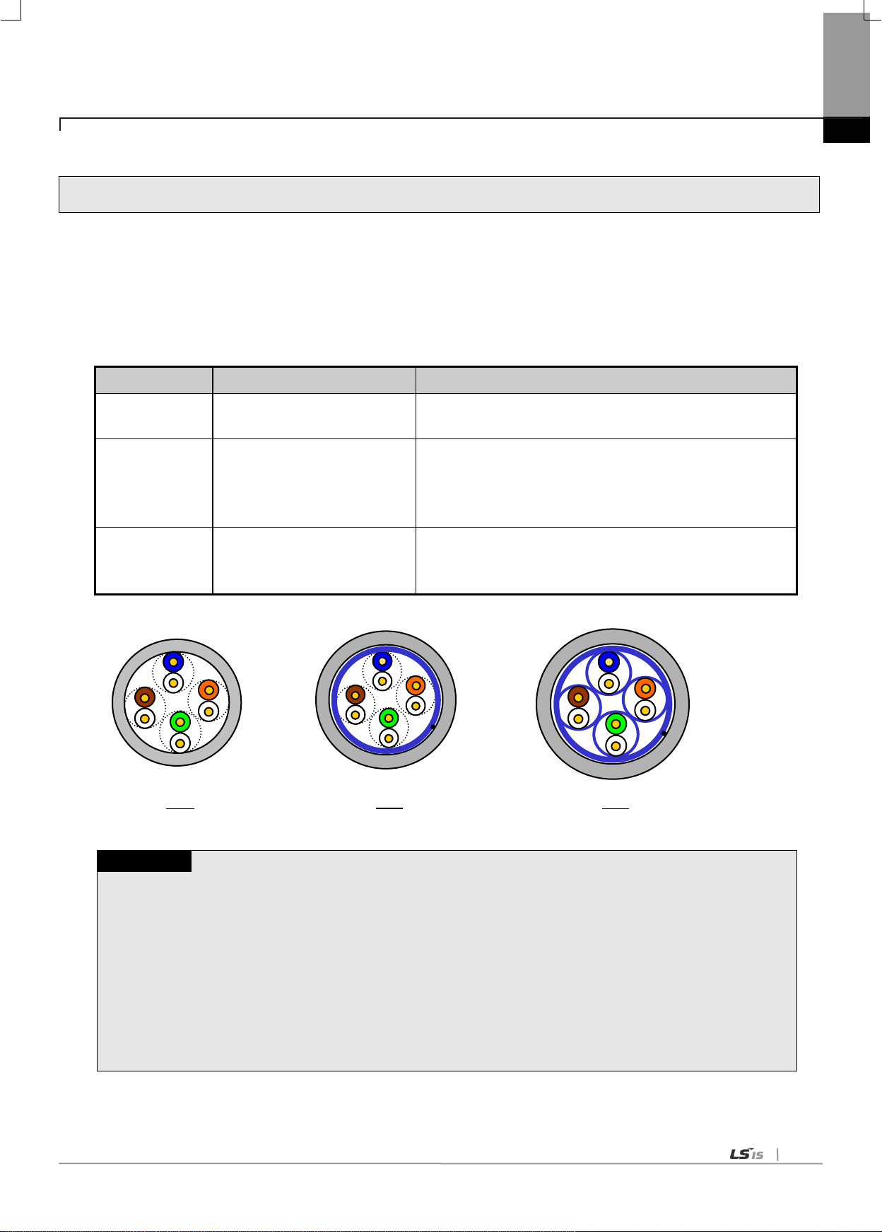
UTP
STP
FTP
2.4.1 UTP cable
(1) Type of cables (shield)
Chapter 2 Product Specifications
UTP cable is classified into 3 types based on the following criteria.
- Shield: classified into 3 (UTP, FTP, STP)
- Frequency band used: classified into 7 (Cat.1~7)
- Fire: classified into 4(CMX, CM, CMR, CMP)
2-10
Classification
Frequency used
(MHz)
Transmission
Speed (Mbps)
Purpose
Category 1
Phonetic Frequency
1
Phone network (2-Pair)
Category 2
4
4
Multi-Pair communication cable
Category 3
16
16
Phone network + Computer network
Category 4
20
20
1) Computer network transmission speed
Up
2) Low-loss communication cable
Category 5 and
Enhanced
Category 5
100
100
1) Digital Phone network +
Computer network
2) Low-loss, broadband cable
Notes
1) Presently classified items are Category 3, 5, En-Cat.5 and Cat.6 inside and outside of the
country, where Category 4 has been replaced by Category 5 and Category 7 is being under
development all over the world as STP structure.
Classifi
cation
Heat
Time
Length
of fire
Smoke
suppression
Reference
CMP
88(kW)
20 min
73m
or less
Restriction
• For ceiling without duct
• High voltage (Plenum) cable
• UL 910 (Plenum test)
CMR
150(kW)
30 min
3.6m
or less
NonRestriction
• Vertical installation
• Non high voltage (Non-Plenum) cable
• UL 1666(Riser test)
CM
21(kW)
20 min
2.4m
or less
NonRestriction
• Standard type
• Non high voltage (Non-Plenum) cable
• UL 1581(VTFT test)
CMX
1(kW)
1 min
0.5m
or less
NonRestriction
• Restriction use
• Non high voltage (Non-Plenum) cable
• UL 1581 (VW-1 test)
Notes
1) Though there is CMG between CM and CMR level, that is not applied to LAN cable such as UTP cable
Ex) CMG: it is CAS FT4 (VTFT test) and similar with CM
→Sample condition (1/2 interval array -> 6 bundles x 6) is different with that of Burner angle
(horizontal→45degrees upward)
Chapter 2 Product Specifications
(2) Classification based on frequency used
(3) Classification based on fire (UL standard)

2-11
Item
Unit
Value
Conductor resistance(Max)
Ω/km
93.5
Insulation resistance(Min)
MΩ·km
2,500
Voltage endurance
V/min
AC 500
Characteristic impedance
Ω(1~100MHz)
100 ± 15
Attenuation
dB/100m
or less
10MHz
6.5
16MHz
8.2
20MHz
9.3
Near-end crosstalk
Attenuation
dB/100m
or less
10MHz
47
16MHz
44
20MHz
42
Item
Value
Cable Type
Twin strands of multi-mode fiber optic cable(MMF)
Connector
SC type connector
Diameter of optical fiber
62.5/125μm (62.5μm fiber optic core and 125μm outer cladding)
Wavelength used
1,350 nm
Attenuation
2dB/1,000m or less
Near-end crosstalk Attenuation
11dB or less
Notes
1) Since the type of the connectable cable used for communication module differs from each other based
on the system configuration and its environment, applicable professional advice will be required prior
to installation.
2) The optical cable may have communication errors due to attenuation if any fingerprint or contamination
is stuck on the sectional end of the cable during its treatment.
Chapter 2 Product Specifications
(4) Example (CTP-LAN5) of Category 5 twisted-pair cable (UTP)
2.4.2 Optical cable
3-1
3.1 Installation Environment
Chapter 3 Installation and Test Operation
This product is of high reliance regardless of installation environment. However, for the sake of reliance and stability of the
system, please pay attention to those precautions described below.
(1) Environmental Conditions
(a) To be installed on the control panel waterproof and dustproof.
(b) No continuous impact or vibration shall be expected.
(c) Not to be exposed to the direct sunlight.
Chapter 3 Installation and Test Operation
(d) No dew shall be caused by rapid temperature change.
(e) Ambient temperature shall be kept 0-55℃.
(2) Installation Work
(a) No wiring waste is allowed inside PLC when wiring or drilling screw holes.
(b) To be installed on a good location to work on.
(c) Don‟t let it installed on the same panel as a high-voltage device is on.
(d) Let it kept at least 50㎜ away from duct or near-by module.
(e) To be grounded in an agreeable place free from noise.
3-2
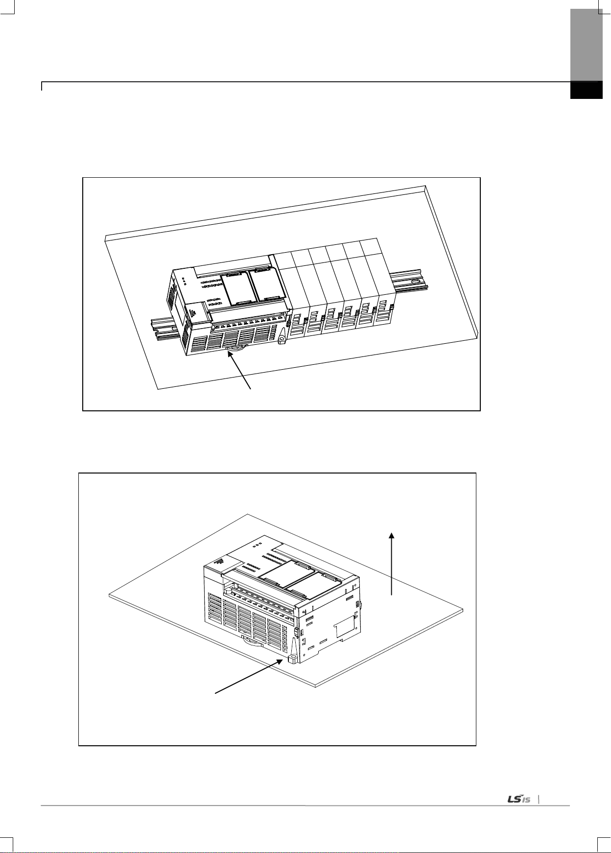
Module fixation (Hook)
Hook for module fixation
Chapter 3 Installation and Test Operation
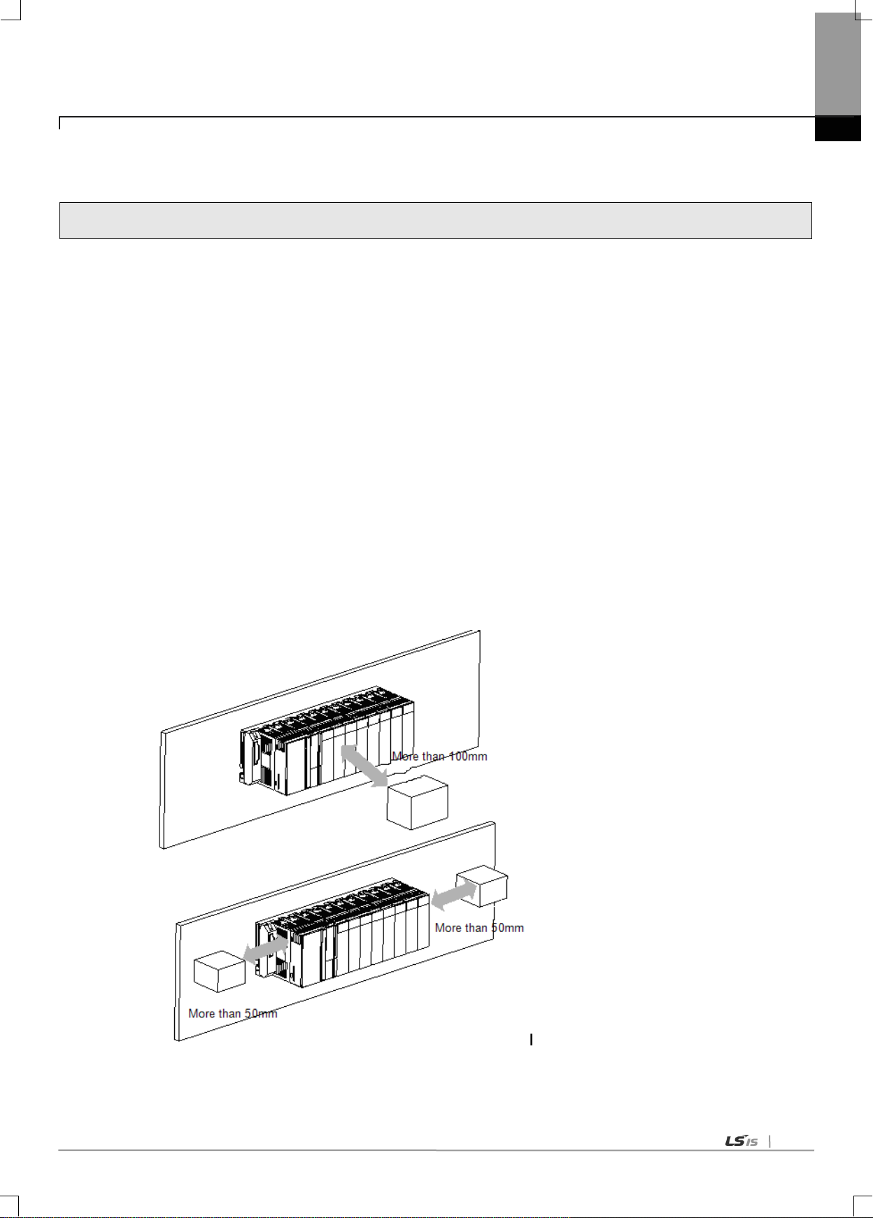
(3) Equipment of XGB module
(a) Eliminate the extension cover at the upper of module.
(b) Push the module and connect it in agreement with hook for fixation of four edges and hook for connection at the bottom.
(c) After connection, get down the hook for fixation at the upper part and lower part and fix it completely.
(4) Detachment of module
(a) Get up the hook for fixation of upper part and lower part and disconnect it.
(b) Detach the module with two hands. (Don‟t force over-applied force.)
3-3
2-Ø 4.5 screw hole
Panel
HOOK for DIN rail
Chapter 3 Installation and Test Operation
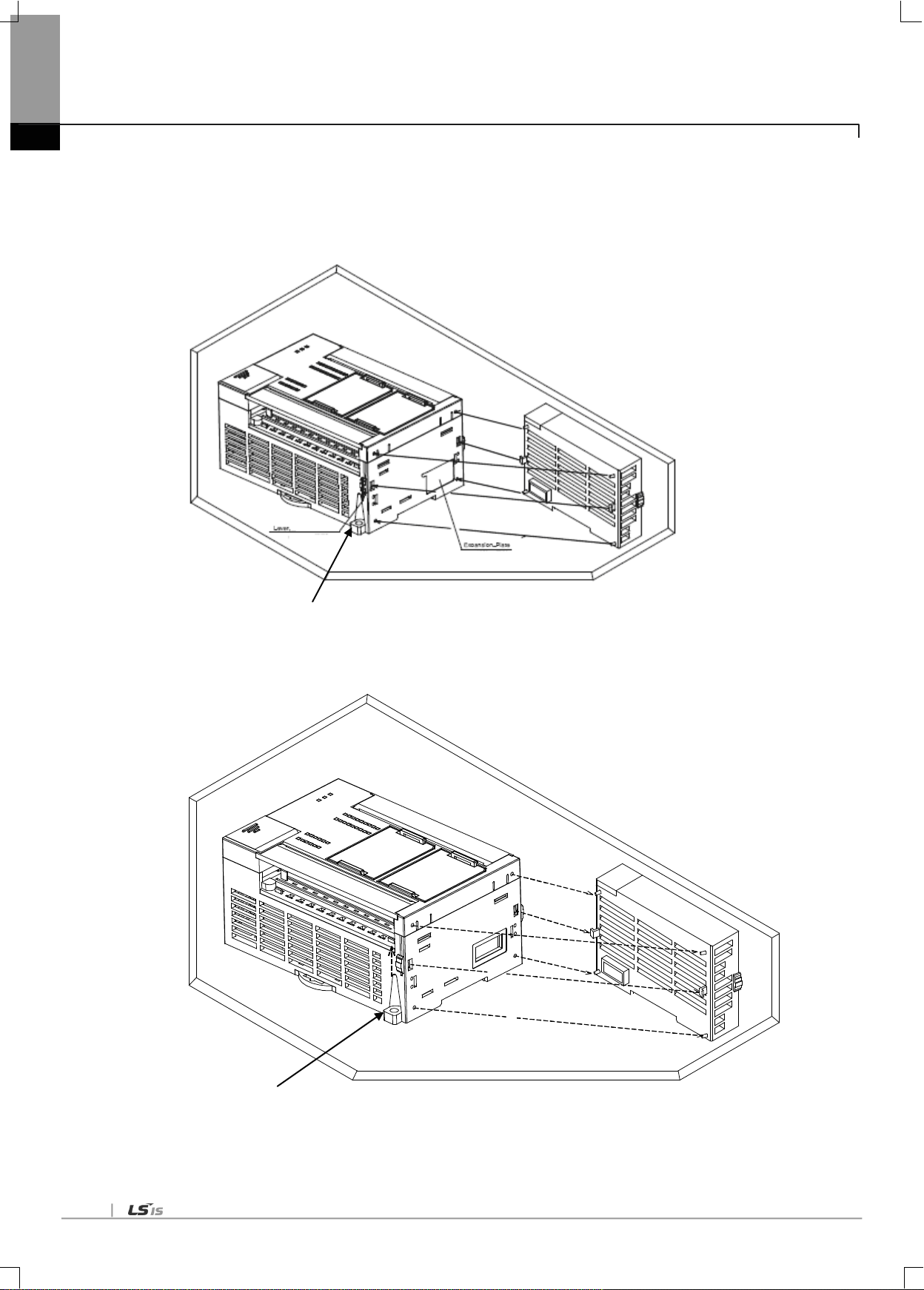
(5) Installation of XGB module
XGB PLC is having hook for DIN rail (rail width: 35mm) so that cab be installed at DIN rail.
(a) In case of installing at DIN rail
- Pull hook for DIN rail at the bottom of module and install it at DIN rail
- Push hook to fix the module at DIN rail after installing module at DIN rail
(b) In case of installing at panel
-You can install XGB compact type main unit at panel directly using screw hole
-Use M4 type screw to install the product at panel.

3-4
Panel
PLC
20㎜or above*3
30㎜ or above
*1
30㎜or above*1
5㎜ or above
5㎜ or above*1
Chapter 3 Installation and Test Operation
(6) XGB module equipment location
Keep the following distance between module and structure or part for well ventilation and easy detachment and attachment.
*1 : In case height of wiring duct is less than 50 mm (except this 40mm or above)
*2 : In case of equipping cable without removing near module, 20mm or above
*3 : In case of connector type, 80mm or above
(7) Module equipment direction
(a) For easy ventilation, install like the following figure.
(b) Don‟t install like the following figure

3-5
100mm or above
50mm or above
50mm or above
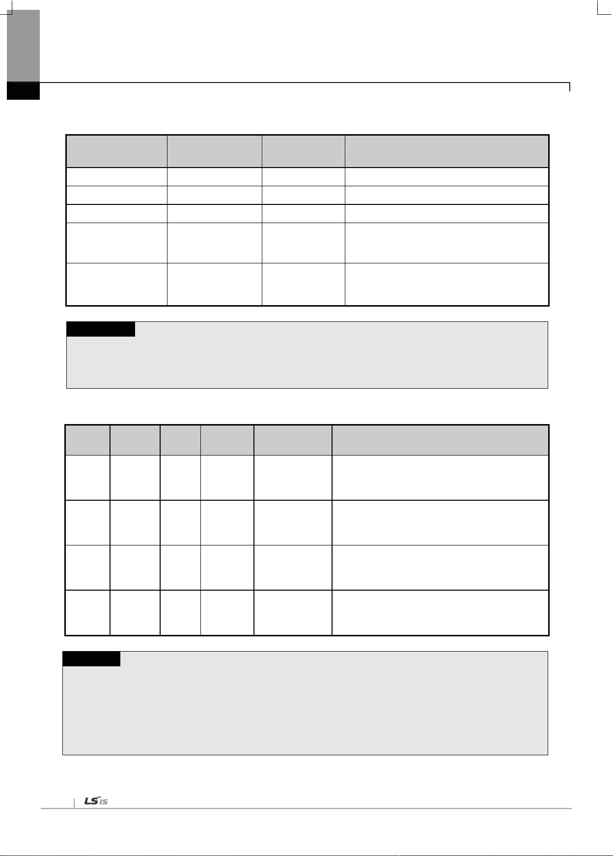
(8) Distance with other device
To avoid radiation noise or heat, keep the distance between PLC and device (connector and relay) as far as the following figure.
Device installed in front of PLC: 100㎜ or above
Device installed beside PLC: 50㎜ or above
Chapter 3 Installation and Test Operation

3-6
3.2 Precaution for Handling
Chapter 3 Installation and Test Operation
The system configuration with RAPIEnet I/F module shall be performed under the following precautions.
(a) Don‟t let it dropped or shocked hard.
(b) Don‟t remove PCB from the case. It will cause abnormal operation.
(c) Don‟t let any foreign materials including wiring waste inside the top of the module when wiring.
(d) Get rid of foreign materials if any.
(e) Don‟t install or remove the module while powered on.
(f) Use standard cable only and let it installed within the maximum distance specified.
(g) Let the communication cable free from the surge and inductive noise generated by or from the alternating current.
(h) Don‟t let wiring too close to hot device and material or in direct contact with oil for long, which will cause damage or abnormal
operation due to short-circuit.
(i) For wiring with pipes, the pipes need grounding.

3-7
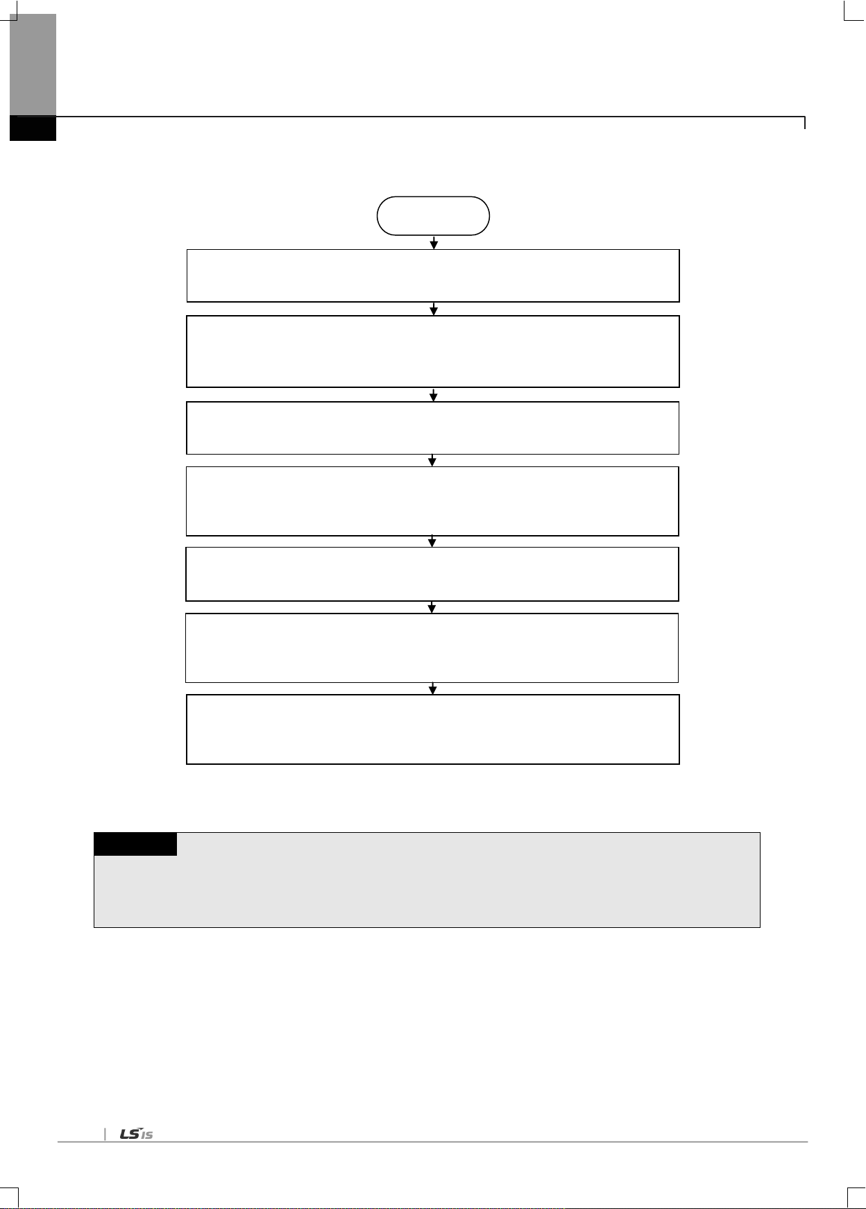
3.3 Sequence from installation to operation
Remark
1) Station number of REPIEnet I/F module is necessary to set due to hardware properties.
: If the station No. is same with other RAPIEnet I/F Module on the
network, conflict will occur.
Execute high speed link parameter
downloading and link enable.
Execute high speed link communication
Begin
Check the functions and specification to
be used.
Install module on the base.
→ Check base/slot position.
Connect module and device with cable,
set module station No.
Turn power on. Check module LED
state. (RUN: green)
Connect XG-PD and XGK/XGI CPU with
cable.
Read IO information at XG-PD → After
“Read IO Information,” the module
appears on themain setting window
Set up P2P parameters (channel, P2P function,
start-up condition, data size/area/type,
corresponding Stn No.)
Execute P2P communication.
Comm.
Execute parameter downloading and link
Set up high speed link parameters.
(comm. module, comm. cycle, emergency
output data, mode, station No., block No.,
data size/area)
The sequence of the product from installation to operation will be described below. After the product installation is complete,
install and configure the system to be operated as specified in the following sequence.
3.3.1 RAPIEnet I/F Module for PLC
Chapter 3 Installation and Test Operation
3-8
Note
1) After setting station number, make sure to turn power on or reset the PC I/F card. The value read from the PC
I/F card at the first time setting of station No. is maintained. Change of station No. during communication is not
applied in the current operation.
Begin
Install I/F card for PC in an empty PCI slot.
→ The slot should be free from interference from other PC cards.
Set the station No. of the I/F card for PC.
→ If the station No. is same with other RAPIEnet I/F Module on the network, conflict
will occur.
Connect the PC I/F card with another network.
→ Construct the system using jig appropriate for the medium.
Turn power on. Check the LED of the PC I/F.
→ Check that the „P‟(Power) and „S‟(Status) LED on the PC I?F card are lit.
Install device driver.
→ PC I/F card cannot be used without device driver.
Carry out programming using the DLL and Lib which are provided.
→ Programming should be made out with the DLL and Lib suitable for desired
functions.
Set the high speed link of the RAPIEnet I/F communication module.
→ Execute the service to enable communication of the RAPIEnet I/F communication
module with the PC I/D card.
Chapter 3 Installation and Test Operation
3.3.2 RAPIEnet I/F module for PC

3-9
3.4 Parameter setting in the XG-PD
Parameter
Lower
menu
Setting item
Details
Setting
PLC
PC
P2P
Comm.
Module
setting
Base
Module position
○
-
Slot
0 ~ 11 ○ -
P2P block
P2P function
READ ○ -
WRITE ○ -
Conditional flag
XGT device ○ -
Command type
Single ○ -
Continuous ○ -
Data type
Bit
○
-
Byte ○ -
Word ○ -
Double Word ○ -
Long Word ○ -
No. of variables
1 ~ 4 ○ -
Destination station
On/Off ○ -
Destination station
No.
0 ~ 63 ○ -
Setting
Read area/
Save area /Data size
○
-
Parameter
Setting item
Details
Setting
PLC
PC
HS link
Mode
Send/Receive
○
○
Station No.
0 ~ 63
○
○
Block No.
0 ~ 63
○
○
Read area
XGT device
○
○
Read area word size
1 ~ 200
○
○
Save area
XGT device
○
○
Save area word size
1 ~ 200
○
○
Contents of parameter setting in XG-PD are as follows.
3.4.1 Parameter setting
(1) P2P parameter
Chapter 3 Installation and Test Operation
(2) High speed link parameter

3-10
3.5 I/O Allocation and Device Information
Classification
XGK-CPUE
XGK-CPUS
XGK-CPUA
XGK-CPUH
XGK-CPUU
Max. expanded
stages
1stage
3 stages
3 stages
7 stages
7 stages
Max. no. of I/O
Module install
24 Modules
48 Modules
48 Modules
96 Modules
96 Modules
Max. I/O point
1,536 points
3,072 points
3,072 points
6,144 points
6,144 points
Max. extended
distance
15m
0 1 2 3 4 5 6 7 8 9 10
11
P0
~
P3F
P40
~
P7F
P80
~
P11F
P120
~
P15F
P160
~
P19F
P200
~
P23F
P240
~
P27F
P280
~
P31F
P320
~
P35F
P360
~
P39F
P400
~
P43F
P440
~
P47F
0 1 2 3 4 5 6 7 8 9 10
11
P00
~
P0F
P10
~
P1F
P20
~
P3F
P40
~
P7F
P80
~
P8F
P90
~
P10F
P110
~
P12F
P130
~
P16F
P170
~
P18F
P190
~
P19F
P200
~
P21F
P220
~
P23F
P
W
R
I
1
6
I
1
6
I
3
2
I
6
4
O
1
6
O
3
2
O
3
2
O
6
4
I
3
2
O
3
2
O
1
6
O
3
2
C
P
U
Slot No.
P
W
R
I
1
6
I
1
6
I
3
2
I
6
4
O
1
6
O
3
2
O
3
2
O
6
4
I
3
2
O
3
2
O
1
6
O
3
2
C
P
U
Slot No.
Chapter 3 Installation and Test Operation
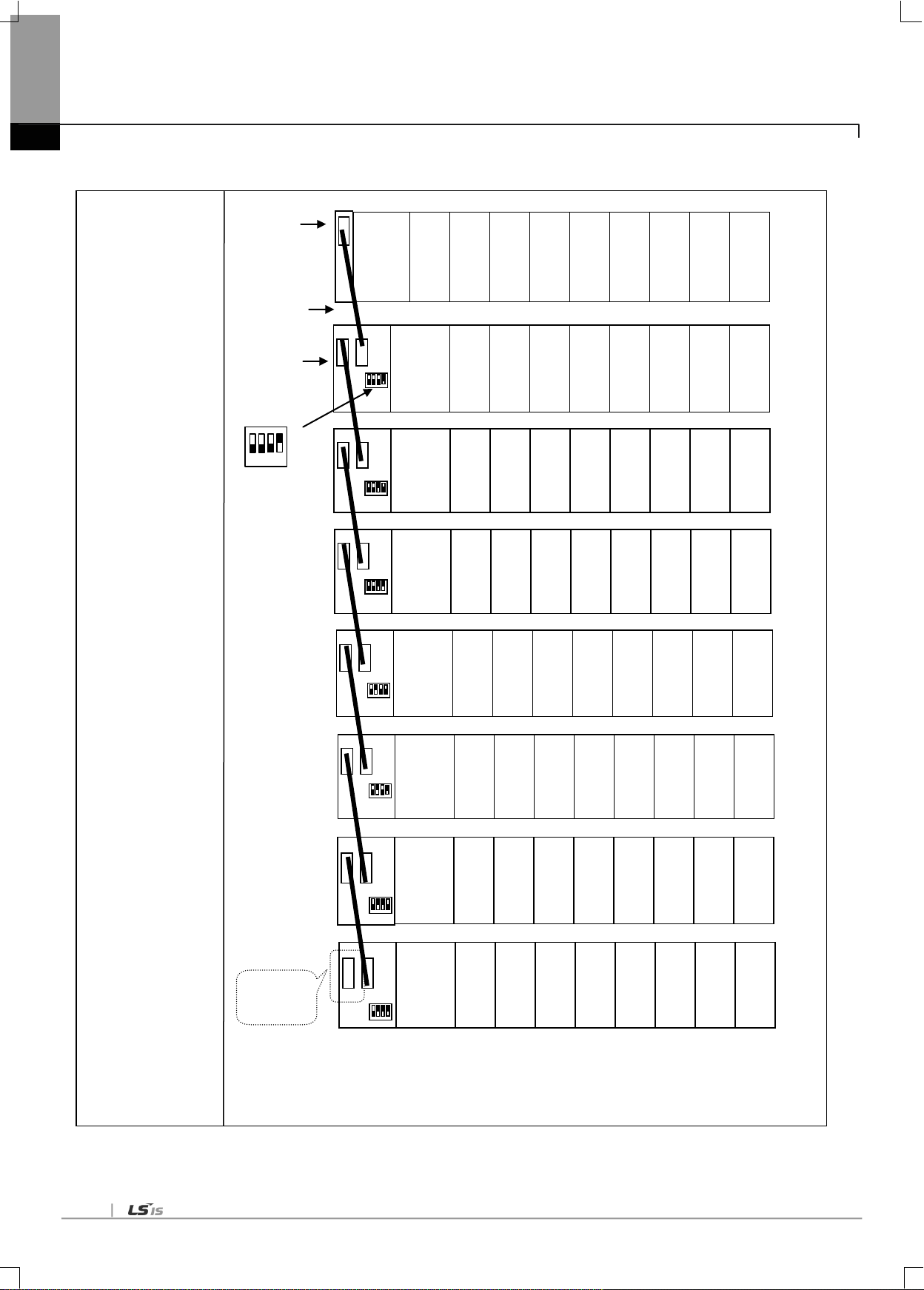
3.5.1 I/O allocation
(1) Using XGK CPU
(a) Configuration method of basic system
The features of Basic system consisted by connecting the main base and expanded base by a cable are as follows. The number
of steges of expanded base is limited according to the CPU type and the allocation method of I/O No. is available to select the
fixed type and variable type according to the setting of basic parameter.
(b) Allocation of I/O number (Fixed type)
1) Each slot of base is allocated by 64 points regardless module installation and type.
2) For one base, I/O no. of 16 slots is allocated. That is, the start no. of No.1 base becomes P0640.
3) The example of I/O no. of 12 slot base is as below.
(c) Allocation of I/O no. (Variable type)
1) If assigned installation module by I/O parameter, the assigned point is allocated.
2) The slot not assigned by I/O parameter shall be allocated automatically according to actual installatio slot.
3) The slot not assigned by I/O parameter shall be allocated automatically according to actual installation slot
(8 point module shall be allocated by 16 point.)
4) IThe empty slot not assigned by I/O parameter shall be processed by 16 point.
5) Available to assign the point only by I/O parameter without module assignment.
6) The slot installed by special module or communication module is allocated by 16 point.
7) The example of I/O no. of 12 Slot base is as below.

3-11
System Configuration
Example 1
- I/O point fixed
- XGK-CPUH
- 8 slot base
Expanded cable
Main base
(base no.:0)
Base no.
Setting switch: 1
1 2 3 4
Expanded
base
Slot no.:
CPU
P0000
~
P003F
P0040
~
P007F
Power
P0080
~
P011F
P0120
~
P015F
P0160
~
P019F
P0200
~
P023F
P0240
~
P027F
P0280
~
P031F
Slot no.:
0 1 2 3 5 4 6
7
P1920
~
P195F
P1960
~
P199F
Power
P2000
~
P203F
P2040
~
P207F
P2080
~
P211F
P2120
~
P215F
P2160
~
P219F
P2200
~
P223F
Slot no.:
P2560
~
P259F
P2600
~
P263F
Power
P2640
~
P267F
P2680
~
P271F
P2720
~
P275F
P2760
~
P279F
P2800
~
P283F
P2840
~
P287F
Slot no.:
0 1 2 3 5 4 6
7
P3200
~
P323F
P3240
~
P327F
Power
P3280
~
P331F
P3320
~
P335F
P3360
~
P339F
P3400
~
P343F
P3440
~
P347F
P3480
~
P351F
Slot no.:
0 1 2 3 5 4 6
7
P3840
~
P387F
P3880
~
P391F
Power
P3920
~
P395F
P3960
~
P399F
P4000
~
P403F
P4040
~
P407F
P4080
~
P411F
P4120
~
P415F
Slot no.:
0 1 2 3 5 4 6
7
P4480
~
P451F
P4520
~
P455F
Power
P4560
~
P459F
P4600
~
P463F
P4640
~
P467F
P4680
~
P471F
P4720
~
P475F
P4760
~
P479F
Slot no.:
0 1 2 3 5 4 6
7
P0640
~
P067F
P0680
~
P071F
Power
P0720
~
P075F
P0760
~
P079F
P0800
~
P083F
P0840
~
P087F
P0880
~
P091F
P0920
~
P095F
Slot no.:
P1280
~
P131F
P1320
~
P135F
Power
P1360
~
P139F
P1400
~
P143F
P1440
~
P147F
P1480
~
P151F
P1520
~
P155F
P1560
~
P159F
Terminal
Resistor
Position
Chapter 3 Installation and Test Operation
(d) Maximum configuration
1) Max. configuration of basic system (point fixed)

3-12
System
Configuration
Example 2
- I/O point variable
- XGK-CPUH
- 8 slot base
- When installing
16 point Module
Main base
(base no.:0)
Base no.
setting switch: 1
1 2 3 4
Expanded
base
Slot no.:
CPU
P0000
~
P000F
P0010
~
P001F
Power
P0020
~
P002F
P0030
~
P003F
P0040
~
P004F
P0050
~
P005F
P0060
~
P006F
P0070
~
P007F
Expanded cable
Slot no.:
0 1 2 3 5 4 6
7
P0080
~
P008F
P0090
~
P009F
Power
P0100
~
P010F
P0110
~
P011F
P0120
~
P012F
P0130
~
P013F
P0140
~
P014F
P0150
~
P015F
Slot no.:
0 1 2 3 5 4 6
7
P0160
~
P016F
P0170
~
P017F
Power
P0180
~
P018F
P0190
~
P019F
P0200
~
P020F
P0210
~
P021F
P0220
~
P022F
P0230
~
P023F
Slot no.:
0 1 2 3 5 4 6
7
P0240
~
P024F
P0250
~
P025F
Power
P0260
~
P026F
P0270
~
P027F
P0280
~
P028F
P0290
~
P029F
P0300
~
P030F
P0310
~
P031F
Slot no.:
P0320
~
P032F
P0330
~
P033F
Power
P0340
~
P034F
P0350
~
P035F
P0360
~
P036F
P0370
~
P037F
P0380
~
P038F
P0390
~
P039F
Slot no.:
P0400
~
P040F
P0410
~
P041F
Power
P0420
~
P042F
P0430
~
P043F
P0440
~
P044F
P0450
~
P045F
P0460
~
P046F
P0470
~
P047F
Slot no.:
0 1 2 3 5 4 6
7
P0480
~
P048F
P0490
~
P049F
Power
P0500
~
P050F
P0510
~
P051F
P0520
~
P052F
P0530
~
P053F
P0540
~
P054F
P0550
~
P055F
Slot no.:
0 1 2 3 5 4 6
7
P0560
~
P056F
P0570
~
P057F
Power
P0580
~
P058F
P0590
~
P059F
P0600
~
P060F
P0610
~
P061F
P0620
~
P062F
P0630
~
P063F
Terminal
Resistor
Position
Chapter 3 Installation and Test Operation
2) Max. configuration of basic system (point variable)
r

3-13
Classification
XGI-CPUU
Max. extension stage
7 stages
Max. number of I/O
module extension
mounted
96 moduls
Max. I/O contact
number
16 points module : 1,536 points
32 points module : 3,072 points
64 points module : 6,144 points
Max. extension distance
15m
I/O number is constantly allocated to 64 points per slot of the base.
Each slot of the base is allocated with 64 points, irrespectively of module mounted or its type.
The position on which a special module is mounted or the number is not limited.
Unlike digital I/O module, a special module is not allocated for any constant I/O number.
A special module is controlled by the exclusive function block and automatically allocated for
the memory.
For instance, the I/O number of 12 slot base is allocated as follows.
Remark
1) The basis base has its base number as „0‟ and the extension base has a switch to set the base number.
2) Operation starts as long as the module type set as I/O parameter and the actually mounted module type coincide.
%QX 0.11.0 ~ 31
%QX 0.10.0 ~ 31
%QX 0.9.0 ~ 15
%IX 0.8.0 ~ 31
Po
wer
I
1
6
I
1
6
I
3
2
I
6
4
O
1
6
O
3
2
O
3
2
O
6
4
I
3
2
O
3
2
O
1
6
O
3
2
C
P
U
Base no. 1
Slot no.
0 1 2 3 4 5 6 7 8 9 10
Chapter 3 Installation and Test Operation
(2) Using XGI CPU
(a) Basic system configuration
3-14
System Configuration
Example 2
- XGI-CPUU
- 8 slot base
- When installing
16 point Module
Basic base
(Base no.:0)
Base no.
Setting switch: 1
1 2 3 4
Expanded base
Slot no.:
0 1 2 3 5 4 6
7
CPU
0.0.0
~
0.0.16
0.1.0
~
0.1.15
Power
0.2.0
~
0.2.15
0.3.0
~
0.3.15
0.4.0
~
0.4.15
0.5.0
~
0.5.15
0.6.0
~
0.6.15
0.7.0
~
0.7.15
Expanded cable
Slot no.:
0 1 2 3 5 4 6
7
1.0.0
~
1.0.16
1.1.0
~
1.1.15
Power
1.2.0
~
1.2.15
1.3.0
~
1.3.15
1.4.0
~
1.4.15
1.5.0
~
1.5.15
1.6.0
~
1.6.15
1.7.0
~
1.7.15
Slot no.:
0 1 2 3 5 4 6
7
2.0.0
~
2.0.16
2.1.0
~
2.1.15
Power
2.2.0
~
2.2.15
2.3.0
~
2.3.15
2.4.0
~
2.4.15
2.5.0
~
2.5.15
2.6.0
~
2.6.15
2.7.0
~
2.7.15
Slot no.:
0 1 2 3 5 4 6
7
3.0.0
~
3.0.16
3.1.0
~
3.1.15
Power
3.2.0
~
3.2.15
3.3.0
~
3.3.15
3.4.0
~
3.4.15
3.5.0
~
3.5.15
3.6.0
~
3.6.15
3.7.0
~
3.7.15
Slot no.:
0 1 2 3 5 4 6
7
4.0.0
~
4.0.16
4.1.0
~
4.1.15
Power
4.2.0
~
4.2.15
4.3.0
~
4.3.15
4.4.0
~
4.4.15
4.5.0
~
4.5.15
4.6.0
~
4.6.15
4.7.0
~
4.7.15
Slot no.:
0 1 2 3 5 4 6
7
5.0.0
~
5.0.16
5.1.0
~
5.1.15
Power
5.2.0
~
5.2.15
5.3.0
~
5.3.15
5.4.0
~
5.4.15
5.5.0
~
5.5.15
5.6.0
~
5.6.15
5.7.0
~
5.7.15
Slot no.:
0 1 2 3 5 4 6
7
6.0.0
~
6.0.16
6.1.0
~
6.1.15
Power
6.2.0
~
6.2.15
6.3.0
~
6.3.15
6.4.0
~
6.4.15
6.5.0
~
6.5.15
6.6.0
~
6.6.15
6.7.0
~
6.7.15
Slot no.:
0 1 2 3 5 4 6
7
7.0.0
~
7.0.16
7.1.0
~
7.1.15
Power
7.2.0
~
7.2.15
7.3.0
~
7.3.15
7.4.0
~
7.4.15
7.5.0
~
7.5.15
7.6.0
~
7.6.15
7.7.0
~
7.7.15
Terminal
Resistor
Position
Chapter 3 Installation and Test Operation
(b) Max. system configuration

3-15
3.6 Installation
Pin No.
Signal
Straight cable between
modules
1:1 cross cable
1
TD+
1-1
1-3
2
TD-
2-2
2-6
3
RD+
3-3
3-1
6
RD-
6-6
6-2
4,5,7,8
Not used - -
Remark
1) Since the structure of 10/100BASE-TX cable is vulnerable to external noise, the cable needs
to be stranded as twisted (two lines twisted with each other) between cables of the pin No.1
and 2 of TD+ and TD- and between cables of the pin No.3 and 6 of RD+ and RD- so to be
strong against noise
2) Contact professional manufacturers for processing cable terminal, manufacture and installation.
8 pin RJ45 plug
Twisted pair cable
3.6.1 Installation of XGL-EIMT and XOL-EIMT
The max. segment length of 100BASE-TX is 1000 m (distance from module to module).
Use Straight cable or Cross cable.
.
Chapter 3 Installation and Test Operation
[Fig. 3.6.1] 100BASE-TX Installation

3-16
Condition
Min. separation distance
2.0 kVA or less
2.5 kVA
5.0 kVA or more
Power line unshielded, or electric facility open or near to
nonmetallic pipe
127 mm
305 mm
610 mm
Power line unshielded, or electric facility near to metallic
pipe buried
64 mm
152 mm
305 mm
Power line inside metallic pipe buried (or equivalently
shielded) near to metallic pipe buried
-
76 mm
152 mm
Remark
1) If voltage is 480 V, rated power is 5 kVA or more, separate calculation is needed.
Chapter 3 Installation and Test Operation
(1) UTP installation
(a) In order to transmit reliable 100Mbps sign with UTP cable, characteristics of patch cord, line cord, patch panel and
DVO (Data Voice Outlet) shall conform to the Category 5 Spec. (EIA/TIA-568A).
(b) Be careful not to allow the length of patch cord to exceed 7m in cross-connect system. If 7m is exceeded, such
subtraction as long as exceeded is required within the allowable value of 90m in Horizontal Distribution System.
(c) The length of line cord shall not exceed 3m in the workstation. If 3m is exceeded, such subtraction as long as
exceeded is required within the allowable value of 90m in Horizontal Distribution System.
(d) When wiring between patch panel and DVO, the pair pitch of UTP cable shall not be loosened over the following
measurements.
* Max. pair pitch loosened: Category 5: 13 mm
Category 3: 26 mm
(e) Use the jumper wire in IDC cross-connect system, and the pair pitch shall not be loosened over the above-specified
measurements either at this time. Especially, be careful not to bend the cable intensely, which may cause not only
damage but also distance between pairs.
* Max. radius of curvature: 4-pair cable : 4 times of external diameter
Cable with 25 or more pairs: 10 times of external diameter
(f) Max. tension strength during wiring shall not exceed 110 N (11.3 Kgf), based on 4-pair cable.
(g) Jumper wire and patch code shall be wired rather loosely. If wired too tight, the characteristics of Category 5 may be
deteriorated. If Tie-wrap is used, be careful not to apply stress on the cable.
(h) When UTP cable is installed, a suitable distance shall be maintained between EMI source and UTP cable.
The suitable distance for each case is as specified in the table below;

3-17
Remark
1) Since the optical cable is vulnerable to impact, pressure, folding and pulling, pay good attention to its treatment.
The optical contact between the connector and the end of the cable may have communication errors if
contaminated, which may result in unavailable communication.
If the cable is installed outdoors, additional countermeasures are required to protect the cable suitably for the
installation environment.
Multi mode
LC type
3.6.2 Installation of XGL-EIMF and XOL-EIMF
[Fig. 3.6.2] 100BASE-FX Installation
Chapter 3 Installation and Test Operation
The max. segment length of XGL-EIMF is 2000 m (distance from this module to the module). Let the module‟s Tx cross-
connected with the other module‟s Rx, and the module‟s Rx with the other module‟s Tx.

3-18
LC
8 pin RJ45
Plug
Twisted pair cable
Chapter 3 Installation and Test Operation
3.6.3 Installation of XGL-EIMH
[Fig. 3.6.3] 100BASE-TX/100BASE-FX installation

3-19
3.7 Test Operation
3.7.1 Precautions for system configuration
a) HS link station No. of all stations shall be different from each other including this module in order to use HS link service.
b) Use the communication cable as specified only. If not, serious error may occur to communication.
c) Check communication cable if disconnected or shorted prior to installation.
d) Tighten up communication cable connector until connected firmly. If cable connection is unstable, serious error may occur to
Chapter 3 Installation and Test Operation
communication.
e) If remote communication cable is connected, keep the cable far away from power line or inductive noise.
f) Since the coaxial cable is not flexible, it is to be diverged min. 30cm away from the connector in communication module. If
the cable is bent at a right angle or transformed compulsorily, cable disconnection or connector damage in communication
module will be caused.
g) If LED operation is abnormal, refer to Chapter 10 Troubleshooting to check for causes and take actions against. Contact
Customer Service center if the error is as before.

4-1
4.1 Available System Configuration
100Mbps Ethernet TP
Total
Max 64 Node
XGT Series PLC System
Max. 64 stations
XGL-EIMT
XGL-EIMT
XOL-EIMT
Chapter 4 System Configuration
Chapter 4 System Configuration
RAPIEnet I/F module can be installed regardless of XGT CPU module. Maximum number of installation is 24 including
basic base and extension base. Among those, 8 modules can be used as P2P service. If you use dedicated protocol, all 24
modules can be used.
Applicable system configuration is described below.
4.1.1 Ring type system with electric module
[Fig. 4.1.1] System configured by electric module
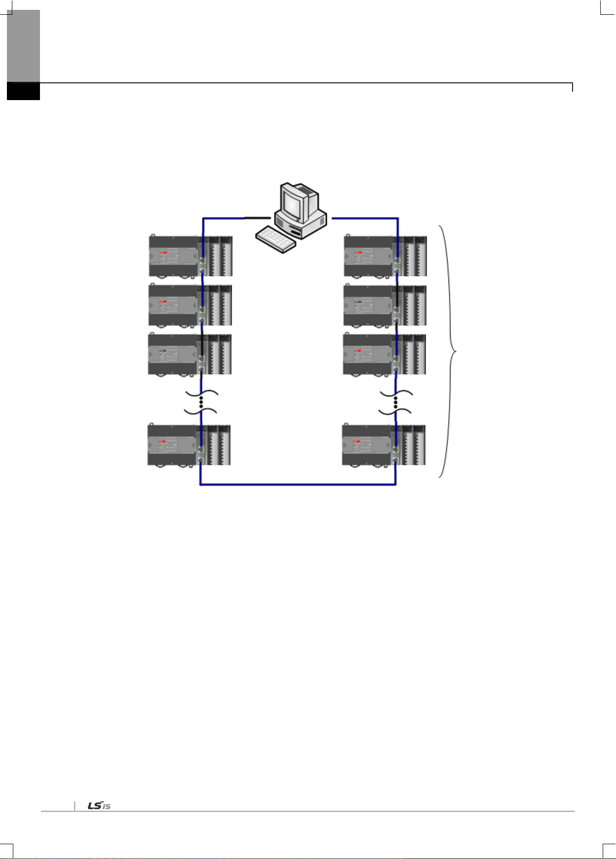
4-2
XBL-EIMT
XBL-EIMT
XOL-EIMT
Max. 64 stations
[Fig. 4.1.2] System configured by XBL-EIMT
Chapter 4 System Configuration

4-3
Total
Max 64 Node
XGT Series PLC System
100Mbps Ethernet Fiber Optic Cable
Max. 64 stations
XGL-EIMF
XGL-EIMF
XOL-EIMF
4.1.2 Ring type system with optical module
Chapter 4 System Configuration
[Fig. 4.1.3] System configured with optical module

4-4
100Mbps Ethernet TP
100Mbps Ethernet Fiber Optic Cable
Total
Max 64 Node
XGT Series PLC System
Maximum 64 stations
XGL-EIMF
XOL-EIMT
XGL-EIMH
XGL-EIMH
XGL-EIMT
XOL-EIMF
Chapter 4 System Configuration
4.1.3 Ring type system with combined module
[Fig. 4.1.4] System configured combined module

4-5
100Mbps Ethernet (Fiber Optic Cable, or TP)
XGT Series PLC System
Total
Max 64 Node
Maximum 64 stations
XGL-EIMF
4.1.4 Line type system with optical module
Chapter 4 System Configuration
[Fig. 4.1.5] Line type system configured optical module
Electric module and combined module also can be used to configure line type system.

5-1
5.1 Introduction
Parameter
Lower menu
Setting item
Range
Details
HS link
Comm.
Module
setting
Module type
RAPIEnet (PLC2PLC) I/F
Setting module type and location
Base
0~7
Slot
0~11
Comm.
Period
setting
Period type
5/10/20/50/100/200/500ms,1s
Setting data TX period
Emergency
output data
setting
CPU error
Latch/Clear
Setting output data in case of CPU
error
CPU stop
Latch/Clear
Setting output data in case of CPU
stop
Block setting
Mode
Send, Receive
Station No.
0~63
In case of RX, partner station
number
Block No.
0~63
Read area
XGT Device area
TX area
Read are word size
1~200
TX size
Save area
XGT Device area
RX area
Save area word size
1~200
RX size
Chapter 5. Communication Parameters
Chapter 5 Communication Parameters
The communication parameters can be classified into high speed link setting parameters and P2P setting parameters.
5.1.1 High-speed link setting parameters
The high speed link is a communication method between the XGT PLC communication modules, which is used exchange
data or information at preset period. It is very useful for the systems which are operated by periodically referring the data of self
or correspondent station. The communication can be set up by simply setting necessary parameters.
To set up the parameters, define the internal area and the area of the correspondent station, size and rate of data, and station
number in the high speed link parameters.
The minimum data size is 1 word (16 points) and the maximum size is 200 words. Communication period can be set from
5ms to 1 second according to the contents of the communication. Communication can be implemented simply by setting
parameters. Large volume of data can be exchanged periodically due to high speed internal data process.
The following table is HS link setting specification.
[Table 5.1.1] High Speed Link parameter

5-2
Paramete
r
Sub-menu
Setting
Setting Range
Description
P2P
P2P Block
P2P function
WRITE
Transmission
READ
Reception
Start-up
condition
Special flags, bit contact point
Set up the operational conditions of frame
Data type
BIT
Set up the data unit of frame
BYTE
WORD
DWORD
LWORD
No. of variables
1~4
Set up the No. of data in the frame
Correspondent
station
Setting/Cancelling
Set up when the correspondent station is
required
Correspondent
station No.
0~63
Set up the No. of the correspondent station
Setting
Read area
XGT device area
Transmission area
Storage area
XGT device area
Reception area
Data size
BIT: 1(user setting not
allowed)
BYTE: 1~1400
WORD: 1~700
DWORD: 1~350
LWORD: 1~175
Size of the data to be transmitted or received
Address
User setting not allowed
(The address automatically
calculated by XG-PD is set up)
The address of the N device of the CPU
module where the data in the variable setting
window is stored
Chapter 5. Communication Parameters
5.1.2 P2P Setting Parameters
While high speed link is a periodical communication, the P2P communication is a services used to communicate with
correspondent station when specific events occur. P2P can be used to transmit error information of a certain station to
correspondent station, or for the communications requested by specific contact point input. While the data size used in the
high speed link is word (16 points) unit, P2P communication can carry out communication with correspondent station
according to the data types such as bit, byte, or word.
(1) P2P service
(a) This service makes the RAPIEnet I/F Nodule act as a client on the network.
(b) At occurrence of predefined events, read from or write in the memory of the correspondent station.
(c) This service is used for the communication with other vendors‟ devices which do not support XGT or mode bus protocol,
or transmission/reception of the desired frame.
(d) Maximum 64 independent P2P blocks can be defined in each module.
The table below presents the specification for setting up P2P parameters.
[Table 5.1.2] P2P Parameters

5-3
Classification
High speed link
P2P
Basic data unit
1word (16 bits)
Available by data type
E.g.) BIT, BYTE, WORD, DWORD, LWORD
Period
5ms, 10ms, 20ms, 50 ms, 100 ms, 200 ms,
500ms, 1s
Executed when the P2P Enable (REQ)
condition is met (timer)
Available
modules
Between RAPIEnet Communication Modules
Between RAPIEnet Communication Modules
Station No.
designation
Set the high speed station No. (for
reception) in XG-PD, and download to the
RAPIEnet I/F Module
Set up in the XG-PD and download to the
RAPIEnet I/F Module
5.1.3 Comparison between high speed link and P2P
The Table 5.1.3 compares the differences between high speed link and P2P services.
The major difference is that the high speed link is for periodical communication of certain data with the correspondent station,
and the P2P is for the transmission of data necessary for specific events.
Chapter 5. Communication Parameters
[Table 5.1.3] Comparison between high speed link and P2P operations

5-4
5.2 Installation and Execution of Software
Chapter 5. Communication Parameters
In order to user the XG-PD software, you need to install the XG5000.
The system specifications required for the execution are as follows.
(1) Personal Computer and Memory
- A set of computer with Pentium and higher CPU and 128MB and more memory.
(2) COM Port
- RS-232C serial port or USB port is necessary.
(3) Hard Disk
- At least, 100MB and more space is necessary.
(4) Mouse
- Mouse to connect with the computer is necessary.
(5) Monitor
- Monitor should have 1024 x 768 and higher resolution.
(6) Windows
- Compatible with Windows 2000/XP. However, XG5000 may be shut down if several applications including other
programs are executed in Windows 98/ME, due to limited memory. Please execute XG5000, based on Windows 2000
or XP.
5.2.1 Installation of XG5000
(1) Execute the installation file.
(2) Installation Wizard will prepare for installation as below.
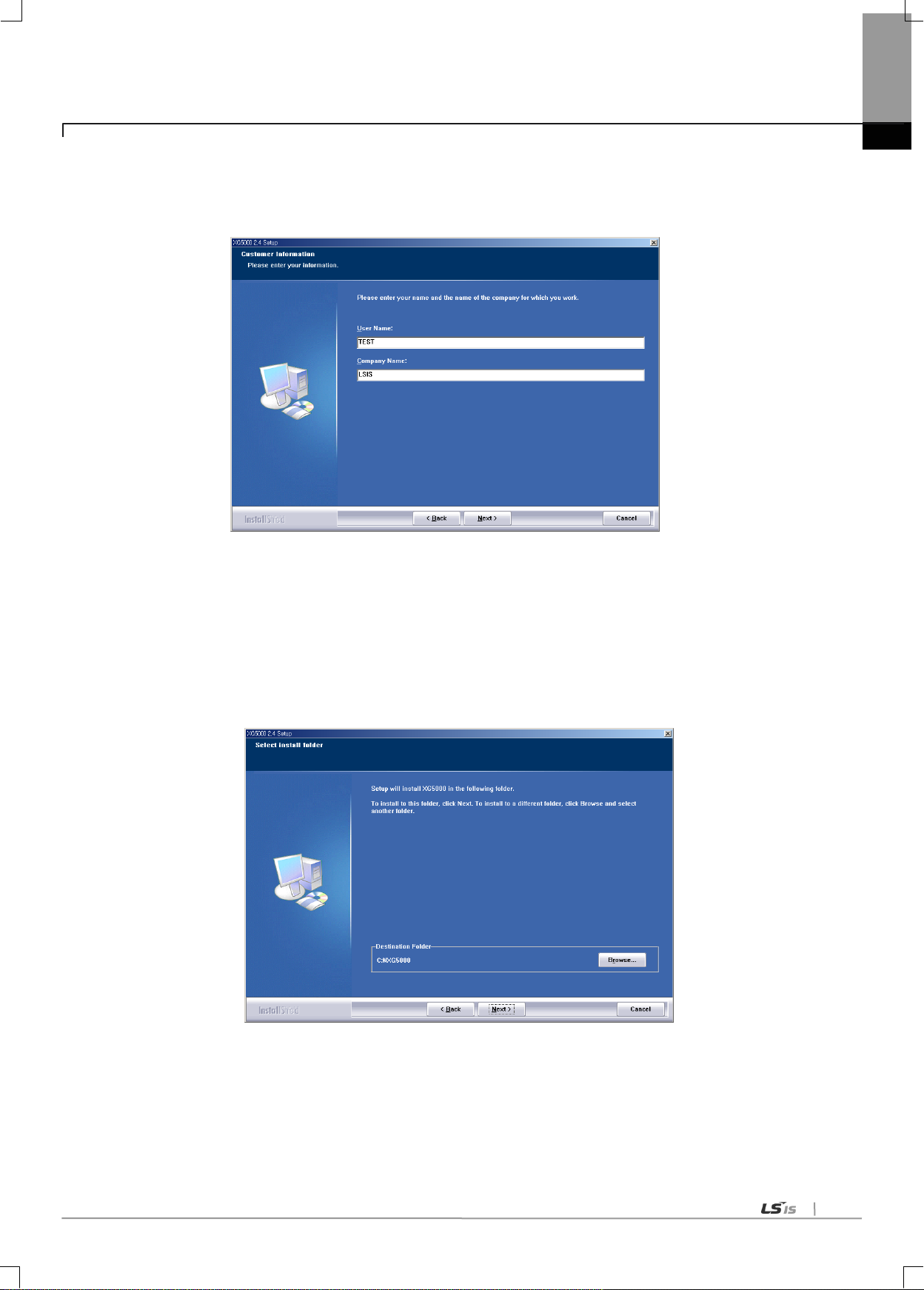
5-5
Chapter 5. Communication Parameters
(3) Click [Next] button, and it shows License Agreement message.
(4) Read carefully and press [Yes]
(5) Enter your name and company name and then click [Next] button.
(6) Select a folder to install XG5000 into. If you want to change the folder, click Browse… button and make or select a new
folder. XG5000 needs about 30M Bytes of installation space in hard disk, which will ask you to select a disk with enough
capacity. If the installation space is not enough, a warning message will be displayed to make the following progress
unavailable
(7) After a folder is selected, click [Next] button.
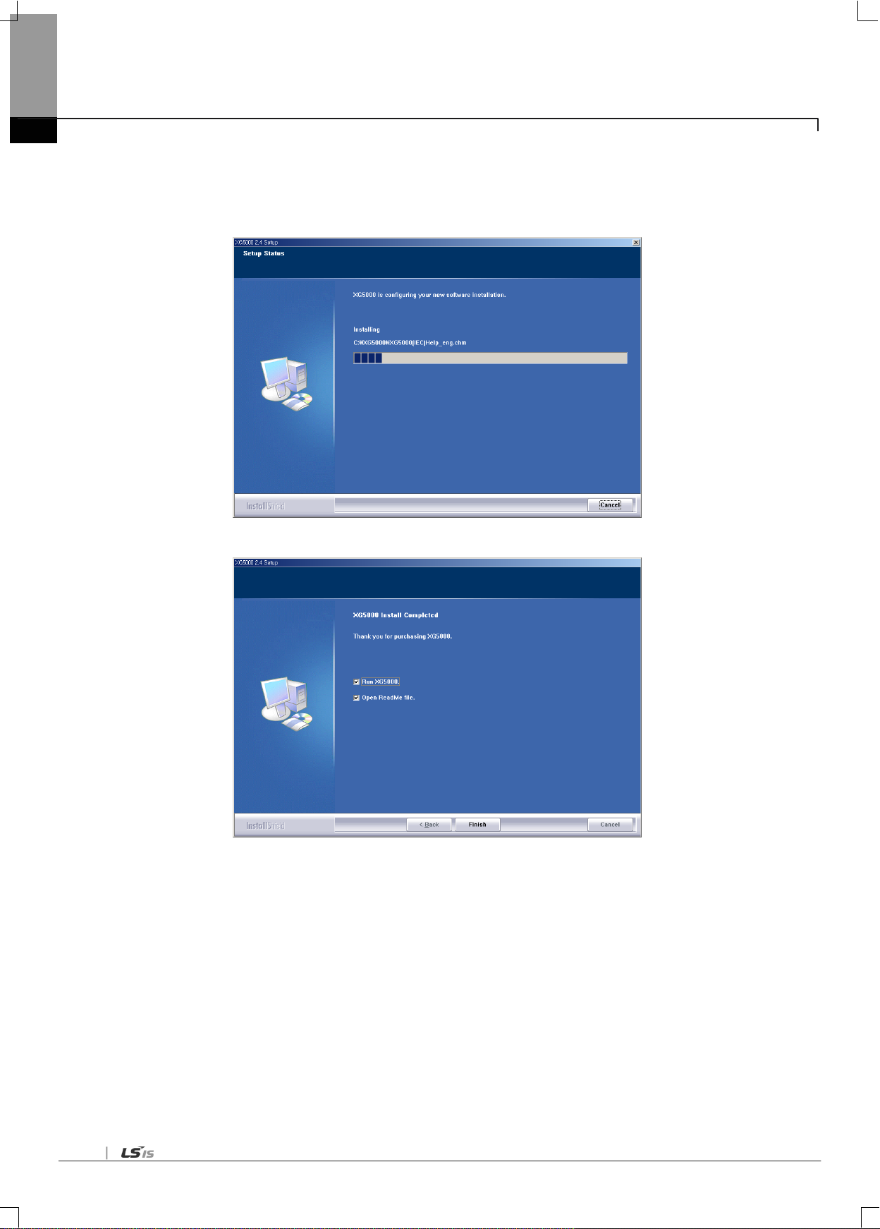
5-6
Chapter 5. Communication Parameters
(8) Check installation folder and click [Next] button.
(9) Installation will be started as shown below.
(10) Wait a second for the installation to be complete.

5-7
5.2.2 Installation of USB device driver
If XG5000 is installed on Windows XP for the first time, It needs USB device driver installation as an additional step. USB
device driver shall be also installed as described below. If your OS is Windows 2000, XG5000 will be installed with USB
device driver automatically. However, in case of Window XP, the driver shall be additionally installed.
(1) Ensure that Drivers folder is created in the folder where XG5000 is installed, and there are 2 driver files of
GmUSBD.sys and GmUSBD.inf in the Drivers folder. If there is no folder or driver file, reinstall XG5000.
(2) Turn PLC Power on and connect USB connector with PC. If connection is established, Find New Hardware Wizard
Dialog Box will be displayed to ask you to install the device driver
Chapter 5. Communication Parameters
(3) From the options of Find New Hardware Wizard Dialog Box, select “Installation from a list or specific location
(Advanced)” and click [Next] to continue.

5-8
Chapter 5. Communication Parameters
(4) Among driver searching options, select “Search for the best driver in these locations” and check “Include this
location in the search”.
(5) Click [Browse] button. On Browse Folder Dialog Box, select Drivers‟ folder where XG5000 is installed.

5-9
Chapter 5. Communication Parameters
(6) Click [OK] button. Then, a computer starts searching for the driver files in the selected folder.
(7) If the computer found the most suitable device driver, you will be asked to decide to install the selected device driver.
Since USB device driver operated stably based on Windows OS, you may click [Continue Anyway] button.
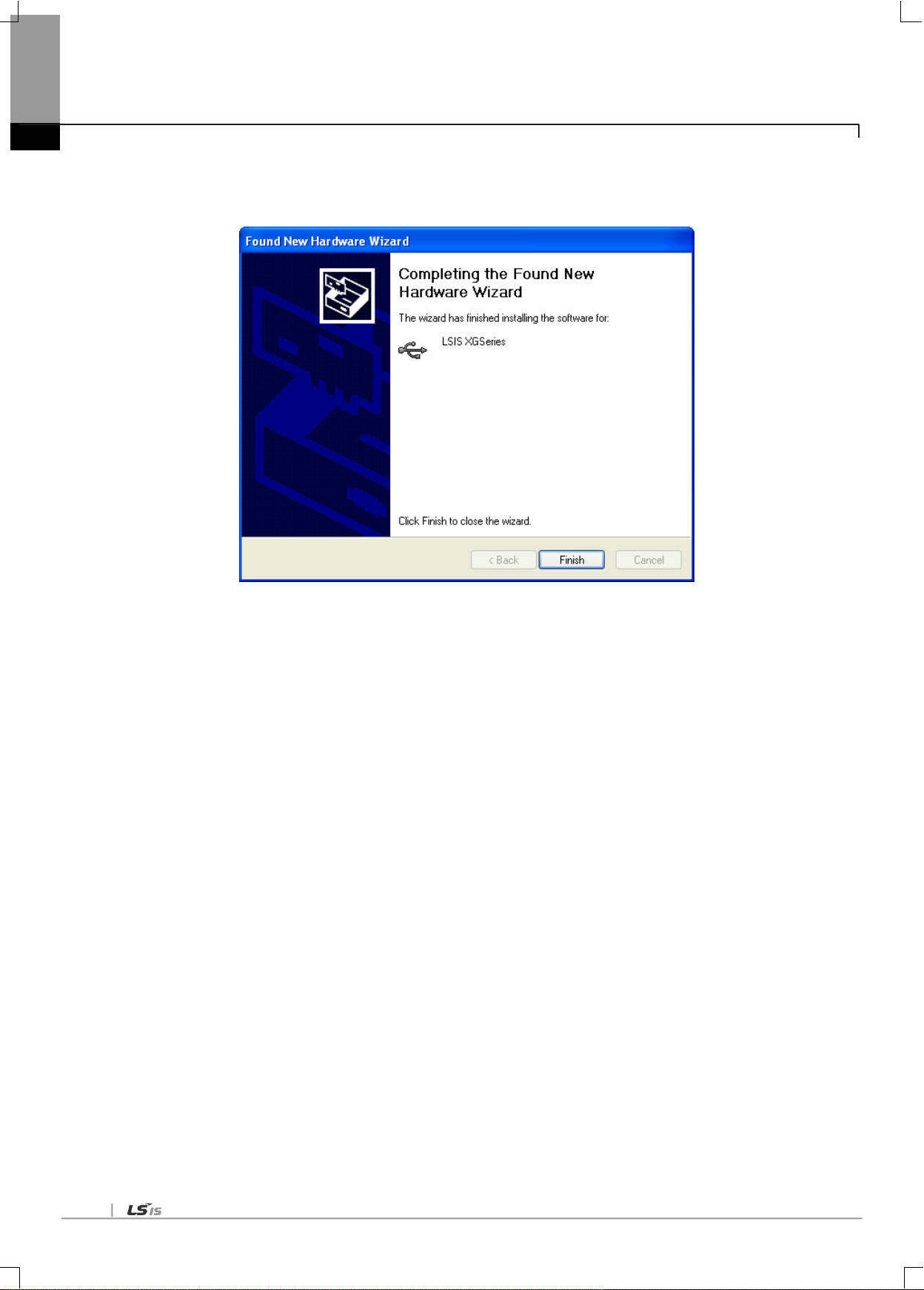
5-10
Chapter 5. Communication Parameters
(8) If the device driver has been installed completely, the Installation Complete Dialog Box will be displayed as follows.
Click [Finish] button to end the installation of the driver.
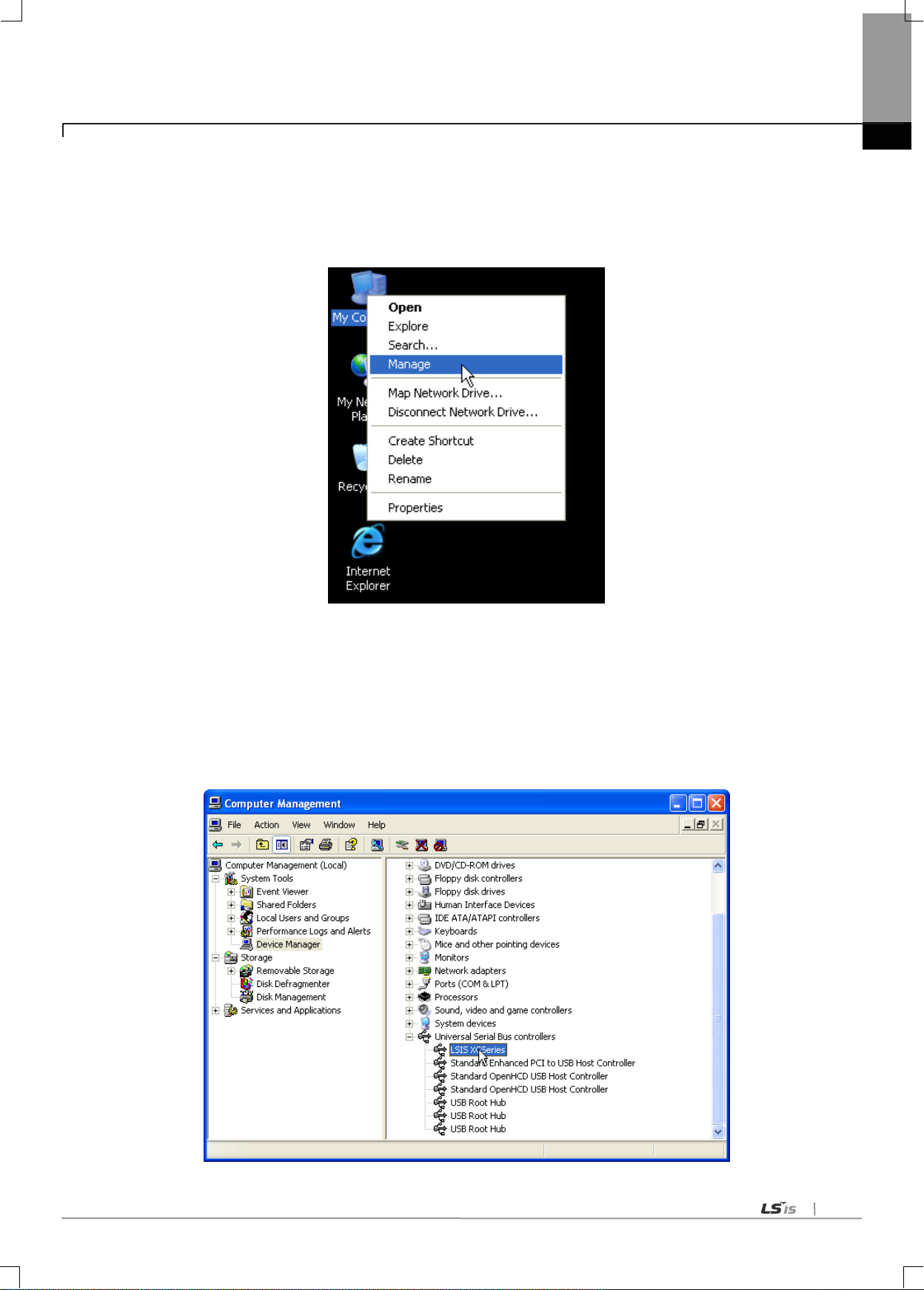
5-11
Chapter 5. Communication Parameters
5.2.3 Confirmation of installed USB device drive
If USB connection is not available, check the installation status of the device driver as follows
(1) Click the right button of the mouse with the cursor on [My Computer] icon on the background screen, and select [Manage] on
the menu.
(2) Computer Management Dialog Box will be displayed as shown in the figure below. On the left tree list of Dialog Box, click
[Computer Management (Local)]-[System Tools]-[Device Manager] in regular order. The items displayed on the right list
may be different according to devices installed on the computer.
(a) Normal case
The USB device driver for XGT PLC has been installed successfully, if the list [LSIS XG Series] appears with the figure
under [Universal Serial Bus Controller].

5-12
Chapter 5. Communication Parameters
(b) Abnormal case
The device driver has not been installed successfully, if the following figure is displayed.
If the USB driver for XGT PLC is not installed successfully, reinstall the USB driver for XGT PLC in the following steps.
[Steps]
(1) On the device driver with the icon with an exclamation mark, click the right button of the mouse. Select [Update Driver]
on the menu.

5-13
Chapter 5. Communication Parameters
(2) H/W Update Wizard Dialog Box will appear. Select the option “Installation from a list or specific location (Advanced)”
and click [Next]. The next sequence is manually the same as in Installation of Device Driver.
If the USB driver for XGT PLC is not installed successfully, reinstall the USB driver for XGT PLC in the following steps
[Steps]
(1) If the device driver has been installed incorrectly or in error, execute H/W Update Wizard. Select the option “Installation from a
list or specific location (Advanced)” and click [Next].

5-14
Chapter 5. Communication Parameters
(2) On search and installation options, select [Don‟t Search. I will choose the driver to install.] and click [Next]
(3) Click [Have Disk…] on the Dialog Box below

5-15
Chapter 5. Communication Parameters
(4) If Installation Dialog Box is displayed on the disk, click [Browse] button.
(5) From the Browse File Dialog Box, move to the folder XG5000 is installed in. Select drivers folder to display GmUSBD.inf file.
With this file selected, click [Open] button.
(6) On the item of „Copy manufacturer‟s files from‟, a directory with the file of the device driver will be displayed. Click [OK] button

5-16
Chapter 5. Communication Parameters
(7) On „Show compatible hardware‟ list of the device driver Select Dialog Box, select “LSIS XGSeries” driver and then click [Next]
button
(8) Hardware Installation Dialog Box will appear. Click [Continue Anyway] to go on with the installation

5-17
Chapter 5. Communication Parameters
(9) Completing the Hardware Update Dialog Box will appear. Click [Finish] button to end the installation of the driver

5-18
5.3 Registration of Communication Module
Chapter 5. Communication Parameters
In order to use RAPIEnet I/F module, communication parameters shall be specified in XG-PD. And for system setting of Cnet I/F
module positioned at an optional place, its applicable module shall be registered in XG-PD. How to register the optionally
positioned RAPIEnet I/F module depends on On/Off line status as described below.
5.3.1 Off-line registration
This method is used when the user writes the parameter related with communication about communication module
that is not connected with PLC.
(1) Execute the XG-PD and select [File]-[New File] or click the icon ( ).
(2) Input the project name, file location and PLC type the user is using.
(3) In the „Standard settings‟, double-click the location of base and slot where the RAPIEnet I/F module is mounted
and activate the „Communication Module Setting‟ window.

5-19
Chapter 5. Communication Parameters
5.3.2 On-line registration
Step (1), (2) of off-line registration is same and the next step is as follows.
(1) Input the project name, file location and PLC type the user is using.
(2) If connection fails, check the connection status. Select [Online] – [Connection settings] or click the icon ( ). There
are many connection types (RS-232C, USB, Ethernet and modem) and depths (Local, Remote 1, Remote 2). For
remote connection, refer to the Chapter 8 Remote Connetcion.
(3) If connection succeeds, lower menu of online is activated.
(4) In order to check the currently mounted modules, select [Online] – [Read IO Information] or click the icon ( ).
Then all currently mounted communication modules in the basic and extension bases are searched and shown in
the Project window.
(5) If previous information of mounted module is different with currently mounted PLC information, the following
message shows to check.
(6) The list of the mounted communication module shows in the Project window.
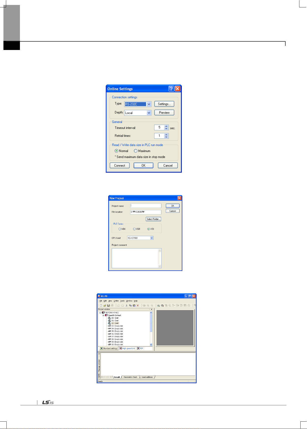
5-20
Chapter 5. Communication Parameters
5.3.3 How to read the parameter saved in the PLC
To read the parameter saved in the PLC, follow the below sequence.
(1) Select the „Open from PLC‟.
(2) After setting the connection type and depth, click the connection.
(3) Input the project name and file location and click the OK.
(4) The user can check the setting value of standard settings and P2P saved in the PLC.

5-21
5.3.4 Module setting method
To use RAPIEnet I/F module., set as the following steps
(1) Direct input in project window
[Online] – [Project Window], Double-clicks the slot number which is mounted REPIE net I/F module.
Communication module setting window is appeared on the main window.
Chapter 5. Communication Parameters
(2) Read I/O Information
Read the IO information of the currently mounted modules by [Online]-[Read IO Information] after connection.
(3) Checking the operation
(a) Select [Oline]-[System Diagnosis] or click the icon ( ).
(b) Click the right button at the relevalet module and click the „Frame Monitor‟ or „Status By Service‟ to check the
communication.
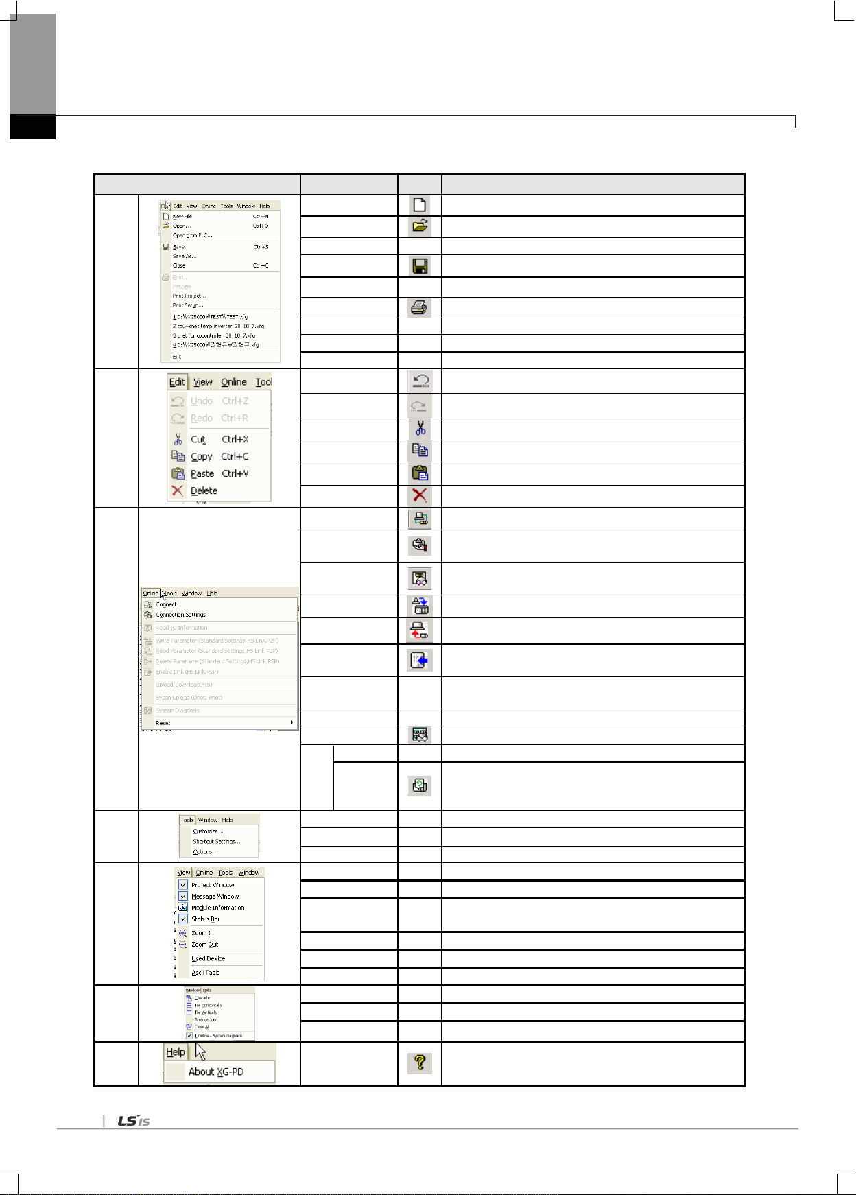
5-22
Menu bar
Menu
Icon
Contents
File
New File
Makes new file
Open...
Opens the saved file
Open from PLC
-
Opens the file saved in the PLC
Save
Saves the current file
Save As
-
Saves the current file with other name
Print Prints
Preview
-
Previews the contents to print
Print Project
-
Prints the designated parameter
Print Setup
-
Sets the print and print direction
Edit
Undo
Return to the previous status
Redo
Cancels the Undo
Cut Cuts the contents
Copy
Copies the contents
Paste
Pastes the cut contents
Delete
Deletes
Online
Connect
Connects the PC with PLC
Connection
Settings
Sets the connection method
Read IO
Information
Reads the IO information of PLC
Write Parameter
Writes the parameter edited in the XG-PD
Read Parameter
Reads the parameter from the PLC
Enable Link
Enables the communication of communication module set by
P2P or high-speed link.
Upload/Download
(file)
-
This menu is not used by the user.
SyCon upload
Reads the data set in the SyCon
System diagnosis
Monitors the operation status of communication module
Reset
Reset PLC
-
Reset
Reset
individual
module
Tools
Customize
-
Edits the tool bar
Shortcut Settings
-
Edits the shortcut
Options
-
Sets the project option
View
Project Window
-
Activates the project window
Message Window
-
Activates the message window
Module
Information
-
Indicates whether system diagnosis is activated or not
Status Bar
-
Activates the status bar
Used Device
-
Indicates the device area used in the parameter
Ascii Table
-
Indicates the Ascii table
Window
Cascade
-
Arrange window like Cascade
Tile - Arrange window like Tile
Arrange Icon
-
Arrange icon
Help
About XG-PD
Indicates the version information of the XG-PD
Chapter 5. Communication Parameters
5.3.5 Menu bar and shortcut of XG-PD
The following is menu bar and short cut of XG-PD.

5-23
5.4 How to set the parameter according to service
5.4.1 High-speed link service
HS link as a communication method between XGT PLC communication modules is used to exchange data or
information with correspondent station periodically for a specific time, through which the changed data of self station or
the correspondent station can be referred to for each other periodically for efficient application to the operation system and
execution of communication only with simple parameters setting.
Parameters can be specified by setting Tx/Rx correspondent station area and self station area as well as data size,
speed and station No. on XG-PD‟s HS link parameters in order to execute communication.
Data size is available from the min. 1 word (16 points) up to 200 words for the communication, communication cycle from
the min. 20 ms up to 10 sec. based on the communication details. It is easy to use since communication with
correspondent station is available only through simple parameters setting. And it is also useful for periodic process of lots
of data at a time thanks to high processing speed of the internal data.
(1) Communication module configuration
In order to use the high speed link, set up communication module and high speed link using the XG-PD, and download
the setting to the CPU.
Chapter 5. Communication Parameters
(a) Module type: PLC2PLC(RAPIEnet)
(b) Base No./slot: position of installation of the communication module
(c) Communication period setting
- Transmission period can be set from 5㎳ to 1s, improving the overall efficiency of communication.
(d) Emergency output data setting
- CPU error: at CPU error, check whether the transmission data information clear is set up or not
- CPU stop: at CPU switching to stop, check whether the transmission data information clear is set up or not

5-24
Chapter 5. Communication Parameters
(2) Block setting
(a) Mode: transmission/reception
(b) Station No.: set up correspondent station No. for receiving only
(c) Block No.
This parameter is for communicating large volume of data in multiple areas of a station, by classifying the data in
multiple blocks. The station No. and the clock No. set up at the transmission station are transmitted with the data, and at
the receiver station, data is stored in the storage area when the station and block numbers are same as those set up in
the high speed link parameters. Therefore, the block numbers have to be set at both transmission and reception station
together with the station number. The block numbers cat be set as many as 64 from „0‟ to „63‟ for each station.
Do not allocate multiple block numbers under the same station number.
200 words can be set to one block. The maximum link points are 12,800 words.
The serial No. representing the order of registration, from „0‟ to „127,‟ not in relation with the order of communication.
(d) Read area: enabled when the block type is transmission. This is the area setting of the device for transmission
(e) Storage area: enabled when the block type is reception. This is the area setting of the device for reception.
(f) Data size (word): can be set by 1 ~200. If the data size set up in the reception mode is smaller than that of the data
received, the excess data is not stored. Therefore, only necessary volume of data can be received selectively from the
transmitter station for use.
(3) Writing high speed link parameter
Select „Write Parameter‟ from the Online menu. In the Write Parameter window, check the respective high speed link
and click Confirm button.
…
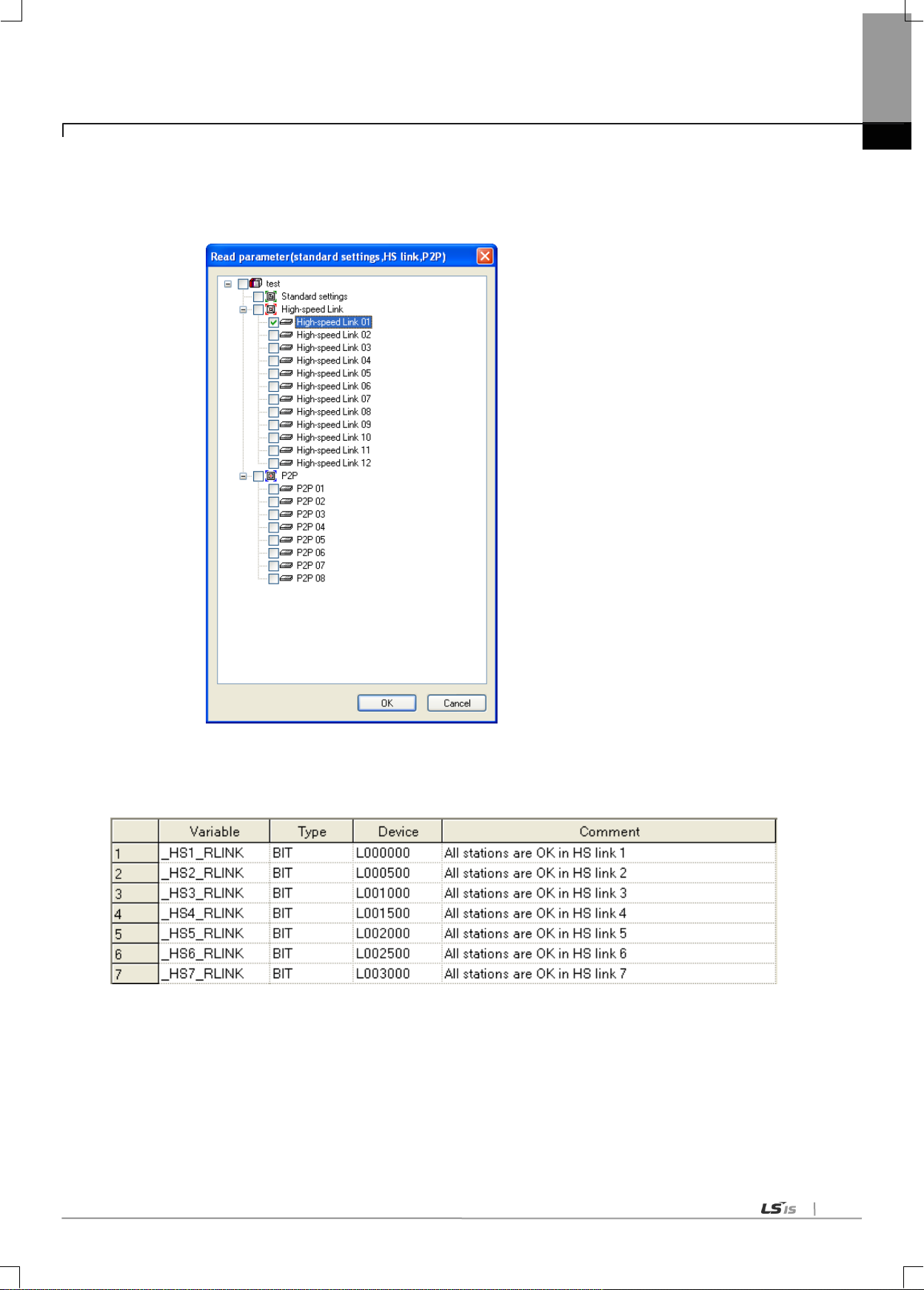
5-25
Chapter 5. Communication Parameters
(4) Read high speed parameter
Select „Read Parameter‟ from the Online menu. Check the desired parameter and click Confirm button to read the high
speed link parameter.
(5) High speed link information
The high speed link information is provided to the XG5000 user as user keyword for use in programming.
Type of high speed link flags
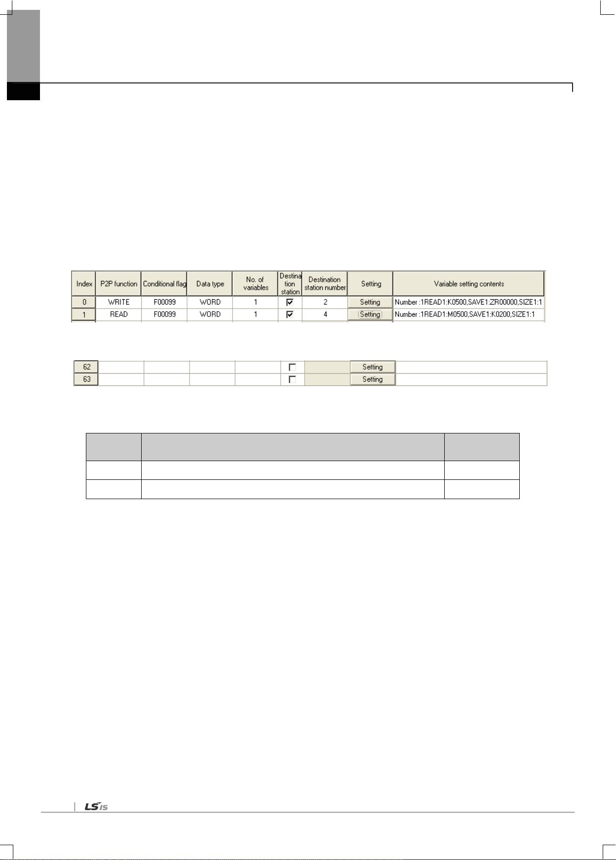
5-26
P2P
Function
Description
Remark
READ
Read the area defined in the partner memory and save the read data.
-
WRITE
Save a part of PLC memory in the area defined in the partner.
-
Chapter 5. Communication Parameters
5.4.2 P2P Service
P2P service acts as the client of the communication module. This service can be used by setting the XG-PD parameters.
Up to 8 P2P parameters can be set up. Each P2P parameter consists with maximum 64 P2P blocks. Major functionalities
of the P2P service are listed below.
(a) The functions of program which have been carried out by PLC are executed by the communication module.
(b) Programming is carried out by setting the parameters in the XG-PD.
(c) Using memory transmission method, when function change or addition is required, the functions can be changed or
added by changing the OS of the XG-PD and communication module, without changing the OS of the CPU module.
(d) Modification during running can be done by adding, changing, or deleting individual parameter block.
(e) Maximum 64 parameter blocks can be monitored.
...
[Fig 5.4.2] Example of P2P parameter setting
P2P service provides read and write functions to support reading and writing of the partners memory.
▶ P2P parameter setting window
▷Maximum 8 P2P parameters can be set up
▷Multiple P2P parameters can be set up for one RAPIEnet I/F Module
However, the Enable is allowed only for one of the P2P parameters for one RAPIEnet I/F Module
▶ P2P edit window
▷maximum 64 P2P blocks can be registered and edited.
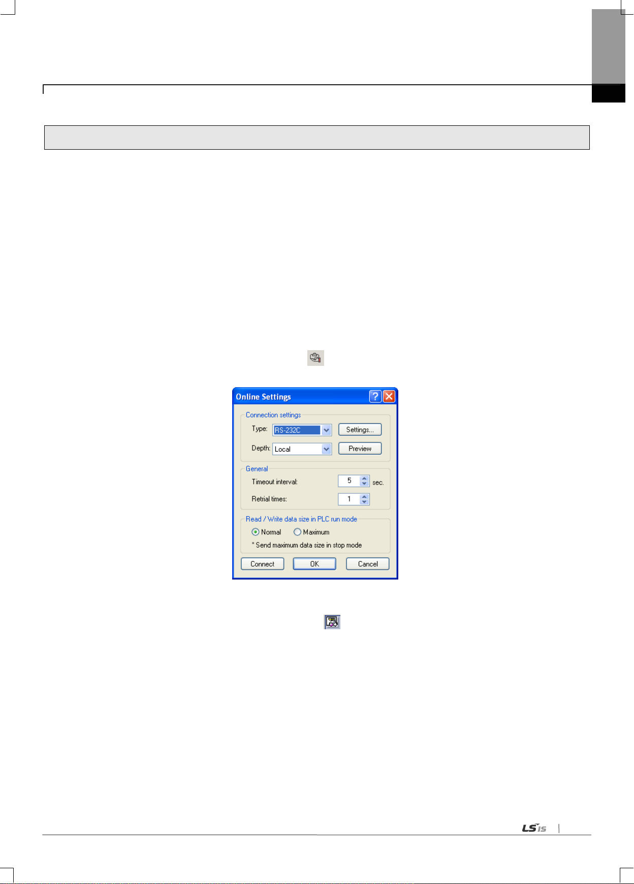
5-27
5.5 Operation Start-up
RAPIEent I/F module‟s operation is divided into P2P service and High-speed link service generally. When setting the
RAPIEnet I/F module as server, follow the 6.3 and when setting the RAPIEnet I/F module as P2P service, follow the
Chapter 7 about parameter setting
5.5.1 XG-PD setting
(1) Overview
This tool defines basic system parameters for the control and management of network in PLC2PLC communication, and
the basic configuration of communication. In the XG-PD, it is divided into the high speed link and P2P communications
which defines the communication system parameters for the PLC2PLC communication module. The parameters set up
by user can be written (downloaded) in the RAPIEnet I/F communication module and read (uploaded) from the RAPIEnet
I/F communication module.
(2) Connection setting
(a) Select [Online]-[Connection settings] or click icon ( ).
(b) After setting the connection option according to user, click the „connection‟.
Chapter 5. Communication Parameters
(3) Reading IO information
Select [Online]-[Read IO Information] or click the icon ( ). Then IO information of currently mounted is shown
on the project window.
(4) Basic setting
The RAPIEnet I/F Module needs no basic setting. In order to register the RAPIEnet I/F Module on the basic setting
window, install the RAPIEnet I/F Module in the slot, reset system, access the system with XG-PD and select „Read IO
Information.‟ As shown in [Fig. 5.5.1]. the RAPIEnet I/F Module appears on the window.

5-28
Chapter 5. Communication Parameters
[Fig. 5.5.1] XG-PD basic window
5.5.2 When operating in high speed link service
(1) Parameter setting
Following window will appear when the high speed link parameter is selected.

5-29
Classification Description
Communication
module settings
Module type
Select PLC2PLC.
Base Number
Select the No. of the base of the installation.
Slot number
Select the No. of the slot of the installation.
Communication
period settings
Period type
Set the data transmission period.
Output data setup
in case of
emergency
CPU error
Set the output data at CPU error.
CPU stop
Set the output data at CPU stop.
Chapter 5. Communication Parameters
(a) Communication module setting (double-click the „High-speed Link 1)
When the communication module has been setup, following window will appear.

5-30
Classification Description
Mode
Send
Transmit data
Receive
Receive data
Station
number
Partner station
number
The No. of the partner module for the reception
Block number
Block number
Set the No. of the transmission and reception blocks
Read area
Address
Memory area of the module to be transmitted.
Read area
Word size
Size (Word)
Set the size of data for transmission.
Save area
Address
The area in the correspondent station where the received data
will be stored.
Save area
Word size
Size (Word)
Set the size of data for reception
Chapter 5. Communication Parameters
(2) Window for setting high speed link parameters
The meanings of the parameters are as follow
(3) Write high speed link parameters (XG-PD Online → Write Parameter)
In the „Write Parameter‟ window, select the pertinent high speed link and click Confirm button.

5-31
Chapter 5. Communication Parameters
(4) Read high speed link parameter
First, connect with the CPU.
After the connection, select „Read Parameter‟ in the online. The window shown in [Fig. 5.5.2] will appear. Select
desired parameter and click Confirm button to read the high speed link parameter setting.
[Fig. 5.5.2] Read Parameter window
(5) Link Enable
(a) Select „Online → Link Enable‟ or click ( ) icon.
(b) Select the set up high speed link and click Write.
(6) Operation check
(a) Select „Online → System Diagnosis‟ or click ( icon.
(b) Click the pertinent module. Right-click the mouse and select frame monitoring or service status to check that
the communication is normal or not..

5-32
Item
Version
XG5000
V3.61 or above
XGR CPU
V1.91 or above
XGI CPU
V3.4 or above
XGK CPU
V3.7 or above
Flag
Data type
Device
Description
_HS_ENABLE_STATE
ARRAY[0..11] OF BOOL
%FX19040
HS link enable/disable current state
_HS_REQ
ARRAY[0..11] OF BOOL
%FX31520
HS link enable/disable request
_HS_REQ_NUM
ARRAY[0..11] OF BOOL
%FX31536
HS link enable/disable setting
_P2P_ENABLE_STATE
ARRAY[0..7] OF BOOL
%FX19072
P2P enable/disable current state
_P2P_REQ
ARRAY[0..7] OF BOOL
%FX31552
P2P enable/disable request
_P2P_REQ_NUM
ARRAY[0..7] OF BOOL
%FX31568
P2P enable/disable setting
Flag
Data type
Device
Description
_HS_ENABLE_STATE
ARRAY[0..11] OF BOOL
%FX15840
HS link enable/disable current state
_HS_REQ
ARRAY[0..11] OF BOOL
%FX16480
HS link enable/disable request
_HS_REQ_NUM
ARRAY[0..11] OF BOOL
%FX16496
HS link enable/disable setting
_P2P_ENABLE_STATE
ARRAY[0..7] OF BOOL
%FX15872
P2P enable/disable current state
_P2P_REQ
ARRAY[0..7] OF BOOL
%FX16512
P2P enable/disable request
_P2P_REQ_NUM
ARRAY[0..7] OF BOOL
%FX16528
P2P enable/disable setting
Flag
Data type
Device
Description
_HS1_ENABLE_STATE
BIT
F09600
HS link 1 enable/disable current state
_HS2_ENABLE_STATE
BIT
F09601
HS link 2 enable/disable current state
_HS3_ENABLE_STATE
BIT
F09602
HS link 3 enable/disable current state
_HS4_ENABLE_STATE
BIT
F09603
HS link 4 enable/disable current state
_HS5_ENABLE_STATE
BIT
F09604
HS link 5 enable/disable current state
_HS6_ENABLE_STATE
BIT
F09605
HS link 6 enable/disable current state
_HS7_ENABLE_STATE
BIT
F09606
HS link 7 enable/disable current state
_HS8_ENABLE_STATE
BIT
F09607
HS link 8 enable/disable current state
_HS9_ENABLE_STATE
BIT
F09608
HS link 9 enable/disable current state
_HS10_ENABLE_STATE
BIT
F09609
HS link 10 enable/disable current state
_HS11_ENABLE_STATE
BIT
F0960A
HS link 11 enable/disable current state
_HS12_ENABLE_STATE
BIT
F0960B
HS link 12 enable/disable current state
_HS1_REQ
BIT
F10300
HS link 1 enable/disable request
_HS2_REQ
BIT
F10301
HS link 2 enable/disable request
_HS3_REQ
BIT
F10302
HS link 3 enable/disable request
_HS4_REQ
BIT
F10303
HS link 4 enable/disable request
_HS5_REQ
BIT
F10304
HS link 5 enable/disable request
_HS6_REQ
BIT
F10305
HS link 6 enable/disable request
_HS7_REQ
BIT
F10306
HS link 7 enable/disable request
_HS8_REQ
BIT
F10307
HS link 8 enable/disable request
_HS9_REQ
BIT
F10308
HS link 9 enable/disable request
Chapter 5. Communication Parameters
* Enable Link through flag
It describes “Enable Link” method through flag. The following XG5000 version, CPU OS version is needed.
Flag list related with “Enable Link”
-XGR
-XGI
-XGK
5-33
Flag
Data type
Device
Description
_HS10_REQ
BIT
F10309
HS link 10 enable/disable request
_HS11_REQ
BIT
F1030A
HS link 11 enable/disable request
_HS12_REQ
BIT
F1030B
HS link 12 enable/disable request
_HS1_REQ_NUM
BIT
F10310
HS link 1 enable/disable setting
_HS2_REQ_NUM
BIT
F10311
HS link 2 enable/disable setting
_HS3_REQ_NUM
BIT
F10312
HS link 3 enable/disable setting
_HS4_REQ_NUM
BIT
F10313
HS link 4 enable/disable setting
_HS5_REQ_NUM
BIT
F10314
HS link 5 enable/disable setting
_HS6_REQ_NUM
BIT
F10315
HS link 6 enable/disable setting
_HS7_REQ_NUM
BIT
F10316
HS link 7 enable/disable setting
_HS8_REQ_NUM
BIT
F10317
HS link 8 enable/disable setting
_HS9_REQ_NUM
BIT
F10318
HS link 9 enable/disable setting
_HS10_REQ_NUM
BIT
F10319
HS link 10 enable/disable setting
_HS11_REQ_NUM
BIT
F1031A
HS link 11 enable/disable setting
_HS12_REQ_NUM
BIT
F1031B
HS link 12 enable/disable setting
_P2P1_ENABLE_STATE
BIT
F09620
P2P1 enable/disable current state
_P2P2_ENABLE_STATE
BIT
F09621
P2P2 enable/disable current state
_P2P3_ENABLE_STATE
BIT
F09622
P2P3 enable/disable current state
_P2P4_ENABLE_STATE
BIT
F09623
P2P4 enable/disable current state
_P2P5_ENABLE_STATE
BIT
F09624
P2P5 enable/disable current state
_P2P6_ENABLE_STATE
BIT
F09625
P2P6 enable/disable current state
_P2P7_ENABLE_STATE
BIT
F09626
P2P7 enable/disable current state
_P2P8_ENABLE_STATE
BIT
F09627
P2P8 enable/disable current state
_P2P1_REQ
BIT
F10320
P2P1 enable/disable request
_P2P2_REQ
BIT
F10321
P2P2 enable/disable request
_P2P3_REQ
BIT
F10322
P2P3 enable/disable request
_P2P4_REQ
BIT
F10323
P2P4 enable/disable request
_P2P5_REQ
BIT
F10324
P2P5 enable/disable request
_P2P6_REQ
BIT
F10325
P2P6 enable/disable request
_P2P7_REQ
BIT
F10326
P2P7 enable/disable request
_P2P8_REQ
BIT
F10327
P2P8 enable/disable request
_P2P1_REQ_NUM
BIT
F10330
P2P1 enable/disable setting
_P2P2_REQ_NUM
BIT
F10331
P2P2 enable/disable setting
_P2P3_REQ_NUM
BIT
F10332
P2P3 enable/disable setting
_P2P4_REQ_NUM
BIT
F10333
P2P4 enable/disable setting
_P2P5_REQ_NUM
BIT
F10334
P2P5 enable/disable setting
_P2P6_REQ_NUM
BIT
F10335
P2P6 enable/disable setting
_P2P7_REQ_NUM
BIT
F10336
P2P7 enable/disable setting
_P2P8_REQ_NUM
BIT
F10337
P2P8 enable/disable setting
Chapter 5. Communication Parameters
▶ How to enable link
-HS link/P2P enable/disable setting flag ON HS link/P2P enable/disable request flag ON
▶ How to disable link
-HS link/P2P enable/disable setting flag OFF HS link/P2P enable/disable request flag ON
▶ You can monitor the Enable/Disable state of the each link through “enable/disable current states” flag.

5-34
Classification
Description
Communication
Module Settings
Type
Select PLC2PLC.
Base
Select the No. of the base.
Slot
Select the No. of the slot.
Chapter 5. Communication Parameters
5.5.3 Operating in P2P service
(1) Parameter setting
Following window will appear when P2P Parameter is selected.
(a) Communication module setting
In the P2P window, click the P2P01 to register the module currently in the slot..
The function of each setting is as follows.
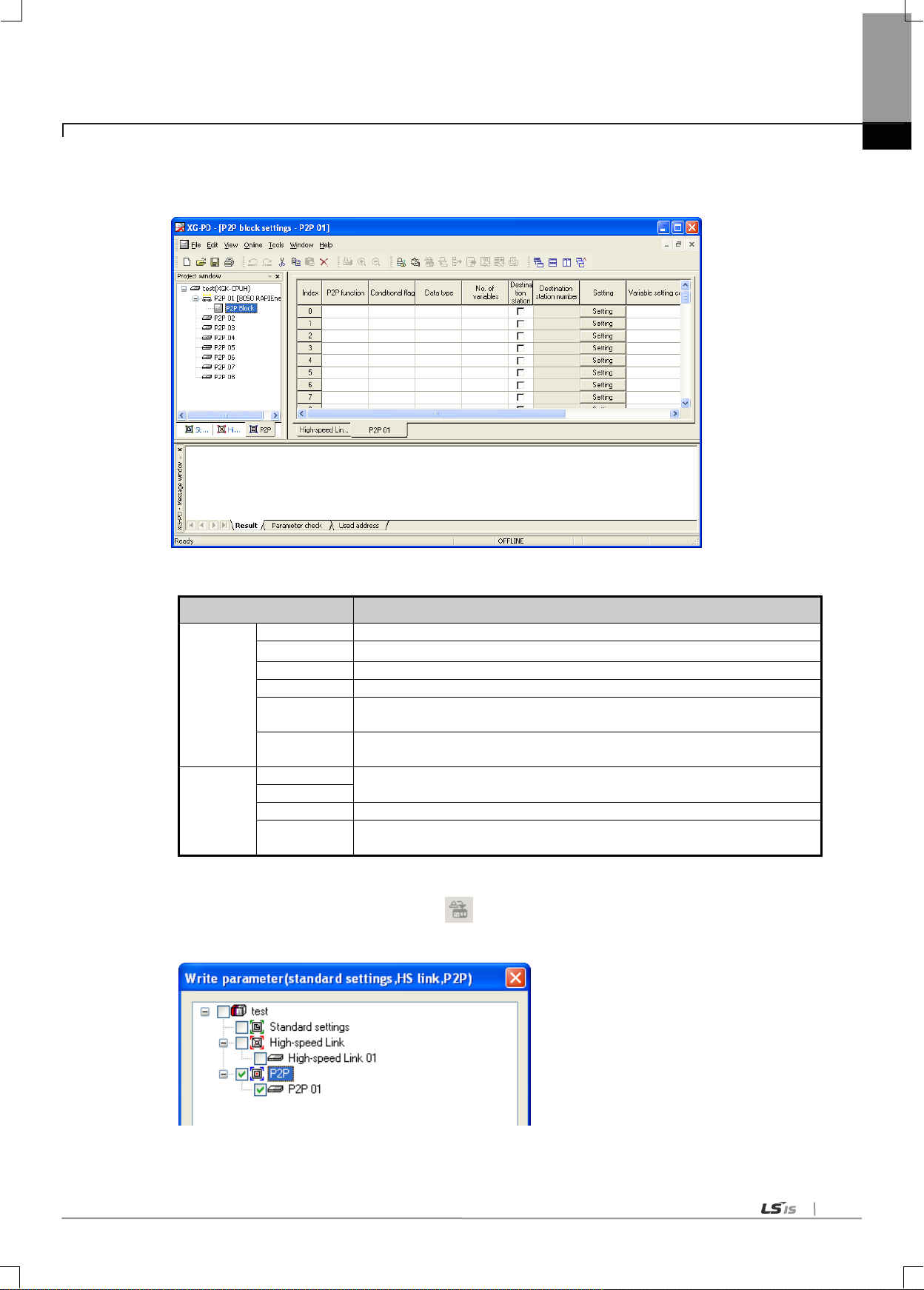
5-35
Classification
Description
P2P Block
P2P function
Select whether to transmit or receive.
Conditional flag
Set up the conditions of the frame operation.
Data type
Set up the data unit of the frame.
No. of variables
Set up the No. of data in the frame.
Destination
station
Set when correspondent station is required.
Destination
station number
Set up the No. of the correspondent station.
Setting
Read area
Set up the XGT device area.
Save area
Data size
Set up the size of the data to be transmitted or received.
Address
The address of the N device area of the CPU module where the data in the
variable setting window will be stored. This address cannot be set up by user.
Chapter 5. Communication Parameters
When the communication module has been set up, P2P block will appear in the P2P window. Click this will show
following window where P2P blocks can be set up.
(b) Setting parameter blocks
(c) Write parameters
1) Select „Online → Write Parameter‟ or click ( ) icon.
2) In the basic setting, select the Basic Setting and the P2P which has been set up, and click Confirm button
3) After clicking the Confirm button and writing parameters, execute individual reset of the pertinent module.

5-36
Chapter 5. Communication Parameters
(d) Enable Link e
1) Select „Online → Link Enable‟ or click ( ) icon.
2) Select the P2P which is set up, and click „Write.‟
(e) Operation check
1) Select „Onloine → System Diagnosis‟ or click ( ) icon.
2) Click the pertinent module. Right-click the mouse and select frame monitoring or service status to check that the
communication is normal or not..

6-1
6.1 Introduction
Classification
Max. communication
points
Max. Tx points
Max. blocks
Max. points per block
XGK CPU
12,800
12,800
128개(0-63)
200
XGI CPU
12,800
12,800
128개(0-63)
200
XGB CPU
12,800
12,800
64개(0-63)
200
Chapter 6 High-speed Link
Chapter 6 High-speed Link
High-speed link (HS Link) is a communication method between XGT PLC communication modules to send and receive data
with HS link parameters setting, which can also allow the user to use XG-PD to exchange data with parameters setting of Tx/Rx
data size, Tx/Rx period, Tx/Rx area and area to save through its data transmission service function.
However, since HS link service uses the subnet broad service, it may have an influence on other communication modules which
use the identical network. Thus, setting as near to the max. Tx/Rx size (200 words) as available per HS link block is
recommended for the user to obtain the greatest communication efficiency with the lowest influence on other modules so to
reduce the sum of blocks.
HS link functions are as specified below;
(1) HS link block setting function
(a) If there are many Tx/Rx areas, up to 96 blocks can be set (32 for Tx and 64 for Rx respectively).
(b) 200 words are available for a block.
(c) Max. link points available are 19,200 words.
(2) Tx/Rx period setting function
Tx/Rx period can be set per block by user for the areas where especially fast Tx/Rx is required and not required
respectively in a Tx/Rx period of 20ms to 10 sec.
(3) Tx/Rx area setting function
Tx/Rx area can be set per data block by user according to I/O address specified.
(4) Providing function of HS link information
Reliable communication system can be easily configured by providing HS link information for user via the user keyword.
[Table 6.1.1] shows communication HS link points whose basic unit is 1 word.
[Table 6.1.1] Max. communication points
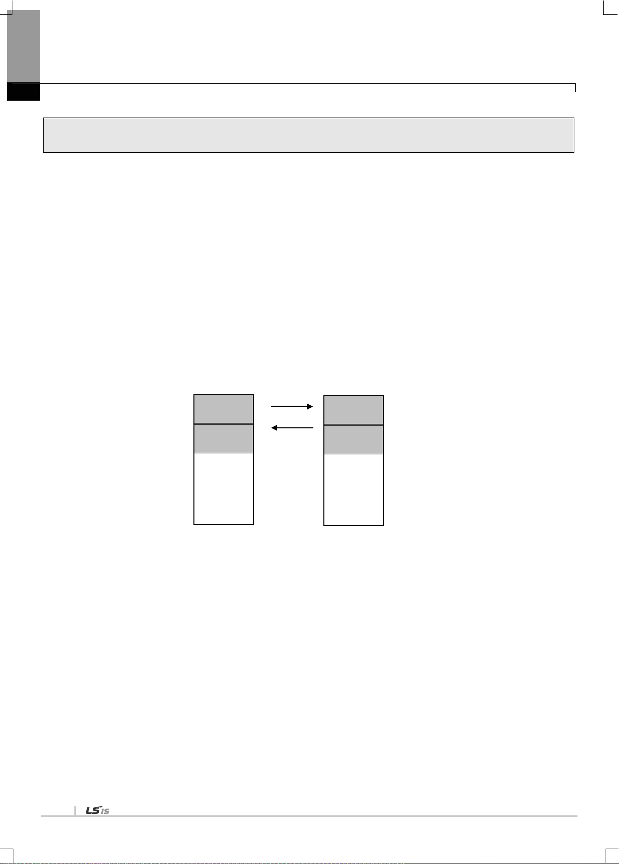
6-2
6.2 HS link Tx/Rx Data Processing
Station 0
Station type: Local
Mode: Tx/Rx
Block No. : 0, 1
Area to read: M0000
Area to save: M0010
Tx/Rx period: 200ms
Size: 10
Block 0
Block 1
Station 1
Station type: Local
Mode: Tx/Rx
Block No.: 0, 1
Area to read: M0110
Area to save: M0100
Tx/Rx period: 200ms
Size: 10
Block 0
Block 1
Chapter 6 High-speed Link
HS link application will be described below with the example where FDEnet I/F modules of the stations No.0 and No.1 are to
send and receive the data between each other.
Its setting sequence is as follows;
(a) The station No.0 transmits M0000 data of 10 words to No.0 block.
(b) The data received by the station No.1 is saved on M0010.
(c) The station No.1 receives M0000 data of 10 words from the station No.0 to save on M0100.
(d) M0110 data of 10 words is transmitted to No.1 block.
There are 64 blocks for Tx data and 128 blocks for Rx data in the HS link parameters. The block number can be set 0~63 for
transmission or receiving. The Tx side needs only to decide which data to read and which block to send to without setting the
correspondent station No. when transmitting the data
[Table 6.2.1] Diagram of HS link processing blocks

6-3
6.3 Operation Sequence through High-speed Link
<Select high speed link >. High speedlink window: open the high speed link setting
window of XG-PD
<Seelct high speed link parameters >.
High speed link 1~12: set up according to the No.of the communication
modules in use (select high speedlink 1 whenusing 1 communication module
* For XGB, only High speed link 1~2 are supported
<High speed link setting (link setting)>.
1. Module type: RAPIEnet
2. Slot No.: XGK/I: 0 ~ 11, XGB: 1~10
3. Transmission/reception period: 5ms ~ 1s
< High speed link setting (register list)>.
1. Mode: transmission or reception (transmission cannot be set up, Designate
correspondent station No. for reception)
2. Station No.: 0 ~ 63
3. Block No.
XGK/I: 0 ~ 127 (TX count 64, RX count 128) blocks are available
XGB: 0 ~ 64 (TX count 64, RX count 64) blocks are available
TRX data is classified by station number and block number
4. Read area, Save area
5. Size (1 ~ 200 word)
<Online (after locak access)>.
1. Write: download high speed link parameters from XG-PD to CPU.
<Link allowability setting >.
1. Seelct one of high speed link 1 ~ 12 (For XGB, 1~2)
Enable the High speed link at the XG-PD.
<Destination station setting >.
Set up the destination station in the same manner as hereinabove.
Chapter 6 High-speed Link

6-4
6.4 HS link parameters setting
Chapter 6 High-speed Link
HS link parameters can be specified as selected on the XG-PD‟s HS link screen for applicable items, whose setting sequence
and respective functions are as follows.
6.4.1 HS link parameters setting of XG-PD
(1) Execution of XG-PD
If XG-PD is executed for the first time, the screen will be displayed as shown in [Fig. 6.4.1]. Click XG5000‟s „Tools‟
„Network Manager‟ or click XG-PD icon of XG5000.
[Fig. 6.4.1] Basic screen of XG-PD
(2) Basic setting
In the XG-PD screen, select „Online‟ → „Access‟ to access PLC. Select „Online‟ → „Read IO Information.‟ The RAPIEnet
I/F Module installed on the base appears in the basic setting window as shown in [Fig. 6.4.2].
[Fig. 6.4.2] Basic setting screen
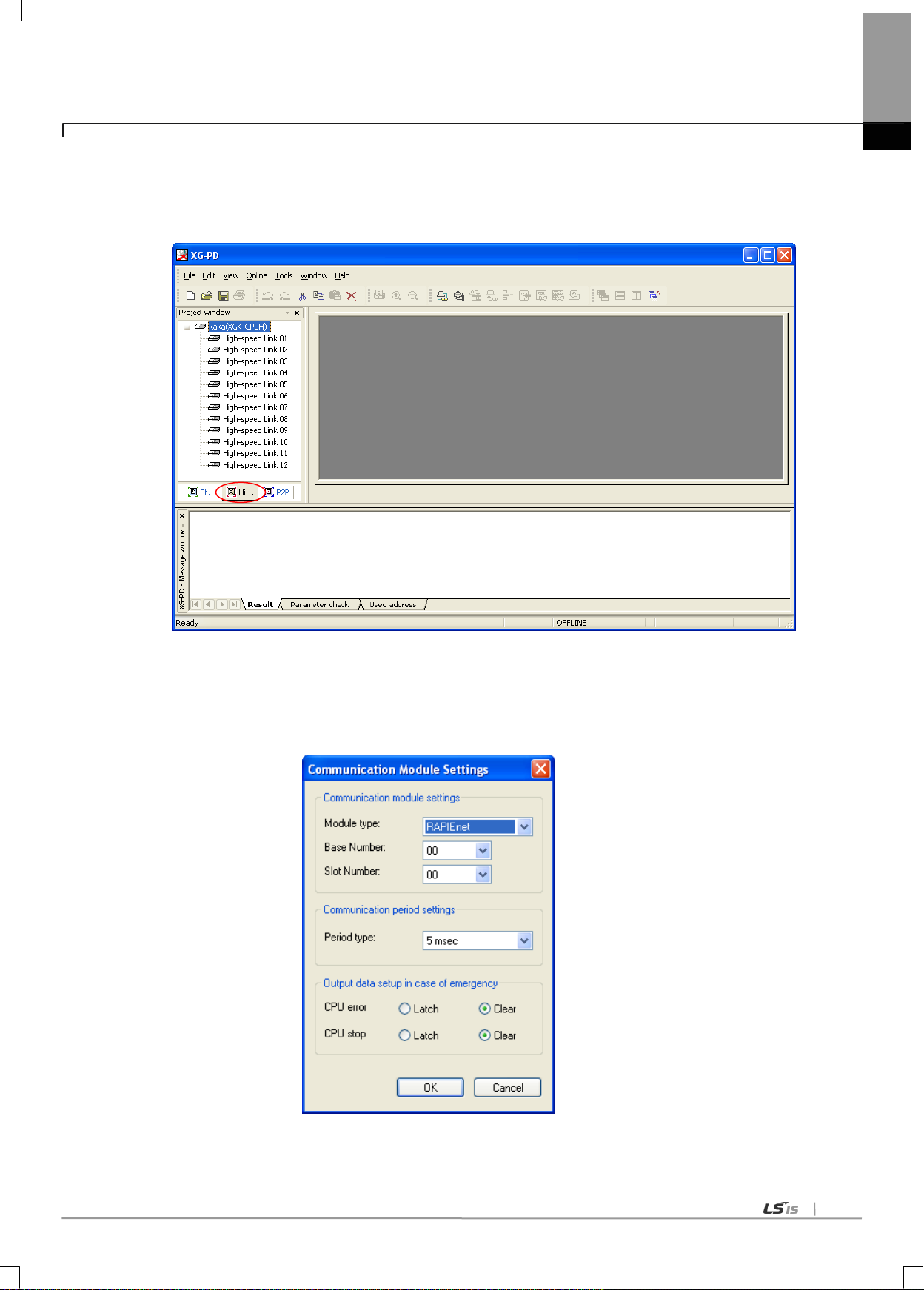
6-5
Chapter 6 High-speed Link
(3) High-speed link parameter setting
(a) Initial screen setting of High-speed link parameter
Select XG-PD‟s HS link window as shown on [Fig. 6.4.3].
[Fig. 6.4.3] Initial setting screen of High-speed link
(b) Setting of communication module and communication period
Double-click one of the HS links 01~12 on the [Fig. 6.4.3] screen to open the setting screen of communication
module and communication period where communication module and communication period can be specified.
[Fig. 6.4.4] Initial setting screen of High-speed link
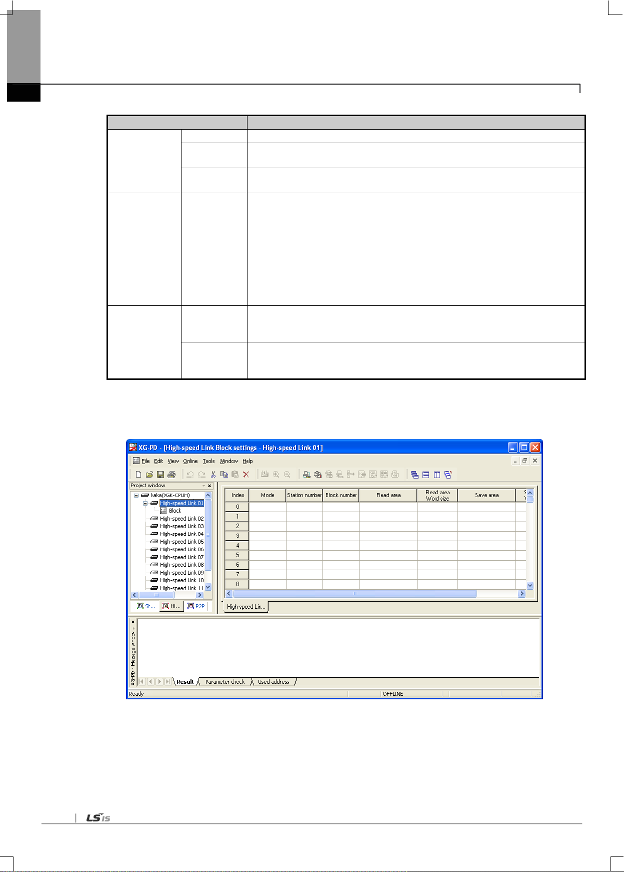
6-6
Item
Details
Communication
module setting
Module type
Specify the communication module installed. (RAPIEnet)
Base no.
Specify the base position the module is installed on (max. 7 stages can be added).
Setting range: 0 ~ 7
Slot no.
Specify the slot position the module is installed on (max. 12 units can be added).
Setting range: 0 ~ 11
Communication
Period setting
Period type
- Set data Tx at periodic intervals.
- Setting range: 5ms, 10ms, 20㎳, 50㎳, 100 ㎳, 200㎳, 500㎳, 1s
(Default period: 5㎳)
- However, Rx data will update the data whenever scanned regardless of the
communication period.
- The communication period will be applied identically to the whole Tx/Rx blocks.
- Up to 4 blocks of data can be sent at a time. Even if this is exceeded, the data will be
divided into 4-block unit for transmission, with which the data size of a block has
noting to do.
Emergency
output data
setting
CPU Error
Set up the output data at CPU error
- Latch: latched to the output just before the CPU error.
- Clear: cleared to „0‟.
CPU Stop
Set up the output data at CPU stoppage
- Latch: latched to the output just before the CPU stoppage.
- Clear: cleared to „0‟.
Chapter 6 High-speed Link
[Table 6.4.1] Setting of communication module and communication period
(c) High-speed link parameter setting
Click [OK] on [Fig.6.4.4] to display [Fig.6.4.5].
[Fig. 6.4.5] Initial setting screen of HS link
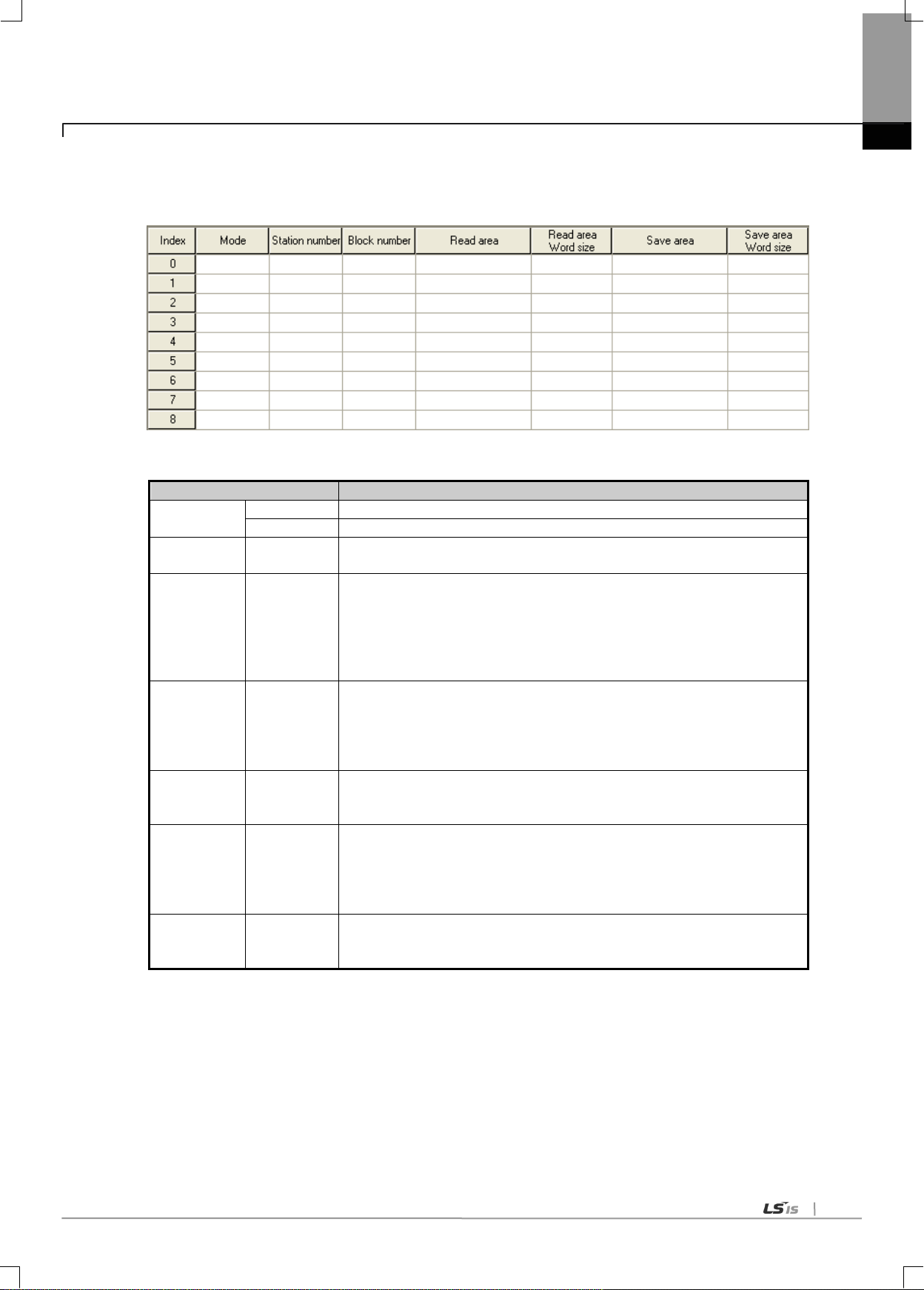
6-7
Classification
Details
Mode
Send
Send data
Receive
Receive data
Station number
Partner station
number
Settable in case of Receive mode
Range: 0 ~ 63
Block number
Block number
Set TRX block
TX block: Max. 64 block (setting range: 0 ~ 63)
Duplicated block number is not allowed
RX block: Max. 128 block (setting range: 0 ~ 63)
Same station number : Duplicated block number is not allowed
Other station number : Duplicated block number is allowed
Read area
Address
Set device area used when receiving
Setting device
- XGK: P, M, L, K, D, T, C, U, N, R, ZR
- XGI: M, I, Q, R, W
It shall not be duplicated with the device address being used in program.
Read area
Word size
Size (Word)
Set data size to send
Setting unit : Word
Setting range :1 ~ 200
Save area
Address
Set device area used when receiving
Setting device
- XGK: P, M, L, K, D, T, C, U, N, R, ZR
- XGI: M, I, Q, R, W
It shall not be duplicated with the device address being used in program
Save area
Word size
Size (Word)
Set data size to receive.
Setting unit : Word
Setting range :1 ~ 200
Chapter 6 High-speed Link
(d) Setting of High-speed link blocks
Double-click „Block‟ on [Fig.6.4.5] to open [Fig.6.4.6].
[Fig. 6.4.6] Setting screen of HS link blocks
[Table 6.4.2] High-speed link setting

6-8
Chapter 6 High-speed Link
(4) How to download High-speed link parameters
Click “Online” “Write Parameter” in XG-PD, check the applicable HS link and then click [OK].
[Fig. 6.4.7] Write Parameter Screen
(5) High-speed link parameter setting
Click “Online” “Enable Link” in XG-PD, check the applicable HS link and then click [Write]. If HS link is enabled, on the
module‟s LED display HS LED will be On, when HS link starts.
[Fig. 6.4.10] Link Enable Screen

6-9
6.5 High-speed link information
Classification
Run-link
Link-trouble
Tx/Rx status
Operation Mode
Error
HS link status
Information type
Whole
information
Whole
information
Individual
information
Individual
information
Individual
information
Individual
information
Keyword name
(x=HS link No.)
_HSxRLINK
_HSxLTRBL
_HSxTRX[n]
(n=0..127)
_HSxMOD[n]
(n=0..127)
_HSxERR[n](
n=0..127)
_HSxSTATE[
n](n=0..127)
Data type
Bit
Bit
Bit-Array
Bit-Array
Bit-Array
Bit-Array
Monitor
Available
Available
Available
Available
Available
Available
Program
Available
Available
Available
Available
Available
Available
Chapter 6 High-speed Link
6.5.1 High-speed link flag
With HS link service used to exchange data between communication modules of two or more stations, it provides a checking
method of HS link service status for the user through HS link information so to confirm reliability of the data read from the
correspondent station via the HS link. In other words, the communication module synthesizes the data received up to that time at
intervals of a specific time and lets the user know if HS link operates as in parameters specified by the user through HS link
information where the whole information of Run-link(_HSxRLINK) and Link-trouble(_HSxLTRBL) to provide the whole information
of the communication network, and the individual information of _HSxSTATE, _HSxTRX, _HSxMOD and _HSxERR to provide
communication status for 64 register items in the parameters are contained. The user can use the information in keyword format
when programming, and also monitor the HS link status using the monitor function of the HS link information. Prior to its
application, the user is requested to check the reliability of the Tx/Rx data through HS link information of Run-link and Link-trouble
when operating several PLCs with HS link used. [Table 6.5.1] below shows functions and definition of the HS link information.
[Table 6.5.1] HS link information function
Double-click [Variable/Comment] on the XG5000 project screen to display the flags view screen as shown below on [Fig. 6.5.1].
From this screen drag the applicable device on to the variable monitor window.
[Fig. 6.5.1] Variable monitor window

6-10
Chapter 6 High-speed Link
(1) Run-link ( _HSxRLINK, x=HS link no. (1~12) )
As the whole information it shows whether HS link is normally executed through the user defined parameters, whose
contact will be kept „On‟ if once „On‟ until Link Enable is „Off‟, and also will be „On‟ under the conditions specified below.
① If Link Enable is „On‟.
② If all the register list settings of parameters are specified normally.
③ If all the data applicable to the parameters register list is transmitted and received as specified in the period.
④ If the status of all the correspondent stations specified in the parameters is Run and with no error at the same time.
(2) Link-trouble ( _HSxLTRBL x=HS link no. (1~12) )
As the whole information it shows whether HS link is normally executed through the user defined parameters, which will
be „On‟ if Run-link „On‟ condition is violated when Run-link is On, and will be off if the condition is recovered.
(3) Tx/Rx status ( _HSxTRX[0..127], x= HS link no. (1~12) )
As individual information it shows the operation status of HS link parameters on the register list up to 127 registered
items‟Tx/Rx information. If the Tx/Rx operation of the registered items is agreeable to the Tx/Rx period, the applicable bit
will be On, and if not, it will be Off.
(4) Operation mode ( _HSxMODE[0..127], x= HS link no. (1~12) )
As individual information it shows the operation status of HS link parameters on the register list up to 127 registered items‟
operation mode information just like the max. register number. If the station specified in the register item is in Run mode,
the applicable bit will be On, and if in Stop/Pause/Debug mode, it will be Off.
(5) Error ( _HSxERR[0..127] x=HS link no. (1~12) )
As individual information it shows the operation status of HS link parameters on the register list up to 127 registered items‟
error information just like the max. register number. The error displays the general status of the PLC which fails to execute
the user program. If the correspondent station PLC is normal, it will be Off, and if abnormal, it will be On.
(6) HS link status ( _HSxSTATE[0..127], x= HS link no. (1~12) )
As individual information it shows the operation status of HS link parameters on the register list up to 127 registered items‟
HS link status just like the max. register number, which synthesizes the information of the individual items to display the
general information of the registered items. In other words, if the applicable list‟s Tx/Rx status is normal with the operation
mode of Run and with no error, it will be On, and if the conditions above are violated, it will be Off.

6-11
6.5.2 Monitor of High-speed link information
HS link information can be checked through the variable monitor on the monitor menu after XG5000 is on-line connected, or
through the XG-PD diagnosis service.
(1) Variable Monitor
Variable monitor is a function used to select an item only necessary to monitor by means of XG5000‟s flag monitor function.
Select [View] [Variable Monitor Window] to display the variable register screen as shown on [Fig. 6.5.1] , and there select
[Flag] directly to select and register HS link information flag one by one on the screen of the variable flags list. At this time,
since _HSxSTATE[n], _HSxERR[n], _HSxMOD[n] and _HSxTRX[n] are the flags of array type, the user needs directly to
select the array numbers which stand for the register numbers inside the parameters.
Chapter 6 High-speed Link
(2) High-speed link monitor from the XG-PD diagnosis services
(a) Select XG-PD → „Access‟ → „Online‟ → „System Diagnosis,‟ place the mouse pointer on the XGL-EIMT. Right-click the
mouse button, select “Service Statuses‟ and select the High Speed Link Service tab. A screen shown in [Fig. 6.5.2] will
appear.
[Fig. 6.5.2] Service statuses; high speed link service screen

6-12
Chapter 6 High-speed Link
(b) To monitor the high speed link of another PLC2PLC module on the network, select XG-PD → „Access‟ → „Online‟ →
„System Diagnosis,‟ place the mouse pointer on the XGL-EIMT. Right-click the mouse button, select „Autoscan.‟ A
screen shown in [Fig. 6.5.3] will appear.
[Fig. 6.5.3] Autoscan screen
In the Autoscan window shown in [Fig. 6.5.3], place the mouse pointer on the RAPIEnet I/F Module for which the high
speed link service is to be monitored. Right-click the mouse button and select „Service Statuses.‟ The high speed link
statuses of other RAPIEnet I/F Modules on the network can be monitored, as shown in [Fig. 6.5.4].
[Fig. 6.5.4] High speed link remote monitoring screen
 Loading...