

Right choice for ultimate yield
LSIS strives to maximize customers' profit in gratitude of choosing us for your partner.
Programmable Logic C ontroller
Cnet I/F Module
User’s Manual
Read this manual carefully before
installing,
wiring, operating, servicing
or inspecting this equipment.
Keep this manual within easy reach
for quick reference.
XGL-
CH2A
XGL-
C22A
XGL-C24A
XGT Series
http://eng.lsis.biz

Safety Instructions
Before using the product …
For your safety and effective operation, please read the safety instructions
thoroughly before using the product.
► Safety Instructions should always be observed in order to prevent accident
or risk with the safe and proper use the product.
► Instructions are divided into “Warning” and “Caution”, and the meaning of
the terms is as follows.
This symbol indicates the possibility of serious injury
or death if some applicable instruction is violated
This symbol indicates the possibility of severe or
slight injury, and property damages if some
applicable instruction is violated
Moreover, even classified events under its caution category may develop into
serious accidents relying on situations. Therefore we strongly advise users to
observe all precautions properly just like warnings.
► The marks displayed on the product and in the user’s manual have the
following meanings.
Be careful! Danger may be expected.
Be careful! Electric shock may occur.
► The user’s manual even after read shall be kept available and accessible to
any user of the product.
Warning
Caution

Safety Instructions
Safety Instructions for design process
Please install a protection circuit on the exterior of PLC so that the
whole system may operate safely regardless of failures from
external power or PLC. Any abnormal output or operation from PLC
may cause serious problems to safety in whole system.
- Install protection units on the exterior of PLC like an interlock circuit
that deals with opposite operations such as
emergency stop,
protection circuit, and forward/reverse rotation or install an interlock
circuit that deals with high/low limit under its position controls.
- If any system error (watch-dog timer error, module installation error,
etc.) is detected during CPU operation in PLC, all output signals are
designed to be turned off and stopped for safety. However, there
are cases when output signals remain active due to device failures
in Relay and TR which can’t be detected
. Thus, you are
recommended to install an addition circuit to monitor the output
status for those critical outputs which may cause significant
problems.
Never overload more than rated current of output module nor
allow to have a short circuit. Over current for a long period time may
cause a fire .
Never let the external power of the output circuit to be on earlier
than PLC power, which may cause accidents from abnormal output or
operation.
Please install interlock circuits in the sequence program for safe
operations in the system when exchange data with PLC or modify
operation modes using a computer or other external equipments
Read specific instructions thoroughly when conducting control
operations with PLC.
Warning
Safety Instructions
Safety Instructions for design process
Safety Instructions on installation process
I/O signal or communication line shall be wired at least 100mm
aw ay from a high-voltage cable or power line. Fail to follow this
instruction may caus e mal funct ions from noise
Caution
Use PLC only in the environment specified in PLC manual or
general standard of data sheet. If not, electric shock, fire, abnormal
operation of the product may be caused.
Before install or remove the modul e, be sure PLC power is off. If
not, electric shock or damage on the product may be caused.
Be sure that every module is securely attached after adding a
module or an extension connector.
If the product is installed
loosely or incorrectly, abnormal operation, error or dropping may be
caused. In addition, contact failures under poor cable installation will
be causing malfunctions as well.
Be sure that screws get tighten securely under vibrating
environments.
Fail to do so will put the product under direct
vibrations which will cause electric shock, fire and abnormal
operation.
Do not come in contact with conducting parts in each module,
which may cause electric shock, malfunctions or abnormal operation.
Caution
Safety Instructions
Safety Instructions for wiring process
Prior to w iring works, make sure that every power is turned off. If
not, electric shock or damage on the product may be caused.
After wiring process is done, make sure that terminal covers are
installed properly before its use. Fail to install the cover may cause
electric shocks.
Warning
Check rated voltages and terminal arrangements in each product
prior to its wiring process.
Applying incorrect voltages other than
rated voltages and misarrangement among terminals may cause fire
or malfunctions.
Secure terminal screws tightly applying with specified torque. If
the screws get loose, short circuit, fire or abnormal operation may be
caused. Securing screws too tightly will cause damages to the module
or malfunctions, short circuit, and dropping.
*
Be sure to earth to the ground using Class 3 wires
for FG
terminals which is exclusively used for PLC. If the terminals not
grounded correctly, abnormal operation or electric shock
may be
caused.
Don’t let any foreign materials such as wiring waste inside the
module while wiring, which may cause fire, damage on the product
or abnormal operation.
Make sure that pressed terminals
get tighten following the
specified torque. External connector type shall be pressed or
soldered using proper equipments.
Caution
Safety Instructions
Safety Instructions for test-operation and
maintenance
Don’t touch the terminal when powered. Electric shock or abnormal
operation may occur.
Prior to cleaning or tightening the terminal screws, let all the
external power off including PLC power.
If not, electric shock or
abnormal operation may occur .
Don’t let the battery recharged, disassembled, heated, short or
soldered. Heat, explosion or ignition may cause injuries or fire.
Warning
Do not make modifications or disassemble each module. Fire,
electric shock or abnormal operation may occur.
Prior to installing or disassemb
ling the module, let all the
external power off including PLC power.
If not, electric shock or
abnormal operation m ay occur .
Keep any wireless equipment such as walkie-talkie or cell phones
at least 30cm away from PLC.
If not, abnormal operation may be
caused.
When making a modification on programs or using run to modif y
functions under PLC operations,
read and comprehend all
contents in the manual fully. Mismanagement will cause damages to
products and accide nts.
Avoid any physical impact to the battery and prevent it from
dropping as well.
Damages to battery may cause leakage from its
fluid. When battery was dropped or exposed under strong impact,
never reuse the battery again. Moreover skilled workers are needed
when exchanging batteries.
Caution
Safety Instructions
Safety Instruct ions for waste disp osal
Product or battery waste shall be processed as industrial waste.
The waste may discharge toxic materials or explode itself.
Caution

Revision History
2
Revision History
Version
Data
Remark
Page
V 1.0 ’05.03 First Edition
-
V1.1 ’05.05.19 Add function description
-
V1.2 ’05.19.12 Change available CPU device address
-
V2.0 ’07.01.15 Change XG-PD description
-
V 2.1 ’08.02
1. Adding contents
(1) Production Configuration
(2) Software to use the product
(3) Operation Sequence
(4) I/O assignment and Device Information
(5) General of Communication Parameter
(6) Transmission Standard
(7) How to set transmission Standard
(8) Menu bar and shortcut of XG-PD
(9) Operation Start
(10) Diagnosis Function of XG-PD
<Ch.7 XGT Dedicated Communication>
(11) Summary of Protocol
(12) Frame Structure
(13) XGT Communication Function
(14) Remote Connection
(15) Modem Communication
(16) Communication Command
<Ch.8 Modbus Communication>
(17) General
(18) Modbus Protocol
(19) Structure of Frame
(20) Modbus Server
(21) Modbus RTU/ASCII Client
(22) Frame Monitor
<Ch.9 User-defined Communication>
(23) General
(24) Structure of user definition frame
(25) Frame Monitor
(26) Trouble shooting
1-3
1-4 ~ 1-5
4-3
4-6 ~ 4-13
6-1
6-2
6-25
6-27 ~ 6-28
6-35 ~ 6-37
6-42 ~ 6-48
7-1 ~ 7-47
8-1 ~ 8-31
9-1 ~ 9-11
11-9 ~ 11-11

Revision History
3
Version Data Remark Page
(27) User interface using Visual Basic
(28) Dimension
(29) Index
2. Fixing the contents
(1) Introduction
(2) Characteristics
(3) Performance Specifications
(4) Designation of Parts
(5) Cable Specifications
(6) Terminal Resistance
(7) Channel Operation during Normal Run
(8) Method of Serial Interface
(9) P2P setting parameter
(10) Available System Configurations
(11) Unavailable System Configurations
(12) Communication Module Registration
(13) Safety Instructions
A-18 ~ A-29
A-30
A-31 ~ A-32
1-1
1-2
2-2
2-3
2-4
2-5
3-2
3-4
4-5
5-1~ 5-6
5-7 ~ 5-8
6-20 ~ 6-24
V2.2
’08.07
1. Head office address change
Back cover
2. Adding contents
(1) How to configure XGR basic system
4-8
(2) Available device area per CPU
4-12
3. Fixing the contents
(1) Introduction
1-1,1-3
(2) Product Specification
2-3
(3) Installation and Test Operation
4-4, 4-9
(4) Communication Parameter
6-1, 6-47
(5) XGT dedicated communication
7-3, 7-5
(6) Modbus communication
8-18, 8-24
(7) User defined communication
9-3
(8) Example program
10-7
(9) Diagnosis
11-4
(10) Standard setting window modification
Entire
V2.3
’10.03
1. Characteristics modified
Ch1.2
2. CPU added
Ch1.3.2
3. Content on the remote connection modified
Ch7.4.2
4. Figure and figure number of modem
communication modified
Ch7.5

Revision History
4
V2.4 ’10.06.17 1. 2.1 Change general specification
2. 3.4.1 (2) Change Null modem connection cable
3. Back address change and delete
2-1
3-4
Back cover
V2.5
’11.05
1. How to enable link through flag added
CH6.7.2
V2.6 ’14.01.10
1. Change typographical error
2. Delete XGR main base module description
3. Change RS-485 communication cable direction
4. Not usable system configuration
5. add parity bit Ignore function
6. Change delay time setting typographical error
7. Change direct variable write typographical error
8. Change Modbus RTU typographical error
9. add UDATA instruction description
10. Add example UDATA function
Entire
CH1.3.2, CH2.2,
CH4.5.1
CH3.4.2
CH5.2.1
CH6.1.1, CH6.2.1
CH6.1.1
CH7.2.3
CH8
CH9.5
CH10.6
V2.7 ’14.04.19
Change system configuration Entire
V2.8
’14.11
XG5000 V4.0 UI Updated
Entire
※ The number of User’s manual is indicated right part of the back cover.
Copyright ⓒ 2005 LSIS Co., Ltd All Rights Reserved.
About User’s Manual
1
Congratulations on purchasing PLC of LSIS Co.,Ltd.
Before use, mak e s ure t o c aref u l l y rea d an d u nd er s tand the Us er’s Manual about the functions, perform anc es, instal lat ion and
programming of the product you purchased in order for correct use and importantly, let the end user and maintenance
administrator to be provided with the User’s Manual .
The User ’s Manual describes the product. If necessary, you may refer to the following description and order accordingly. In
addition, you may conne ct our websi te (http://eng.lsis.biz/
) and download the information as a PDF file.
Relevant User’s Manuals
Title Description
XG5000 User’s Manual
XG5000 software user manual describing online function such as
programming, print, m onitoring, deb ugging by using XG K, XGB
CPU
XG5000 User’s Manual
(for XGI, XGR)
XG5000 software us er manual describin g online function such
as programming, print, monitoring, debugging by using XGI,
XGR CPU
XGK/XGB Instructions & Programming
User’s Manual
User’s manual for programming
to explain how to use
instructions that are used PLC system with XGK, XGB CPU.
XGI/XGR Instructions & Programming
User’s Manual
User’s manual for programming
to explain how to use
instructions that are used PLC system with XGI, XGR CPU.
XGK CPU User’s Manual
(XGK-CPUU/CPUH/CPUA/CPUS/CPUE)
XGK-CPUU/CPUH/CPUA/CPUS/CPUE user manual describing
about XGK CPU module, power module, base, IO module,
specification of extension cab le and system configuration, E MC
standard
XGI CPU User’s Manual
(XGI-CPUU/D,CPUU,CPUH,CPUS,CPUE)
XGI-CPUU/D,CPUU,CPUH,CPUS,CPUE user manual
describing about XGI CPU module, power module, base, IO
module, specification of extension cable and system
configuration, EMC standard
XGR redundant series User’s
Manual
XGR- CPUH/F, CPUH/T user manual describing about XGR
CPU module, power module, extension drive, base, IO module,
specification of extension cable and system configuration, EMC
standard
Current user manual of XGL-CH2A, C42A, C22A is written based on the following version.
Related OS version list
Product name OS version
XGK-CPUU, CPUH, CPUA, CPUS, CPUE V2.0
XGI-CPUU/D, CPUU, CP UH, CP US, CPUE V2.1
XGR-CPUH/F, CPUH/T, CPUH/S V1.1
XG5000 V4.0

Contents
1
◎ Contents ◎
Chapter 1 Overview
1.1 Introduction------------------------------------------------------------------------------------------------------------------------------------------------- 1-1
1.2 Characteristics-------------------------------------------------------------------------------------------------------------------------------------------- 1-2
1.3 Product Configuration----------------------------------------------------------------------------------------------------------------------------------- 1-3
1.3.1 Type name indication----------------------------------------------------------------------------------------------------------------- 1-3
1.3.2 Equip-able number per CPU------------------------------------------------------------------------------------------------------------- 1-3
1.4 Software to use the product-------------------------------------------------------------------------------------------------------------------- 1-4
1.4.1 Software check point------------------------------------------------------------------------------------------------------------------- 1-4
1.4.2 XG5000 ---------------------------------------------------------------------------------------------------------------------------------------- 1-4
1.4.3 Check of version----------------------------------------------------------------------------------------------------------------------------- 1-5
Chapter 2 Product Specifications
2.1 General Specifications------------------------------------------------------------------------------------------------------------------------------------ 2-1
2.2 Performance Specifications----------------------------------------------------------------------------------------------------------------------------- 2-2
2.3 Names of Parts--------------------------------------------------------------------------------------------------------------------------------------- 2-3
2.4 Ca ble Specifications-------------------------------------------------------------------------------------------------------------------------------------- 2-4
2.5 Terminal Resis tance-------------------------------------------------------------------------------------------------------------------------------------- 2-5
Chapter 3 Performance Sp ecifications
3.1 Operat ion M ode Setting--------------------------------------------------------------------------------------------------------------------------------- 3-1
3.2 Channe l Op er at i on during Norm a l Ru n ----------------------------------------------------------------------------------------------------------- 3-2
3.3 Channel Operation in Diagnosis Mode (Loop-Back) ------------------------------------------------------------------------------------------ 3-3
3.4 Method of Serial Interface------------------------------------------------------------------------------------------------------------------------------- 3-3
3.4.1 RS-232C interface----------------------------------------------------------------------------------------------------------------------------- 3-3
3.4.2 RS-422/485 interface-------------------------------------------------------------------------------------------------------------------------- 3-5
Chapter 4 Instal lation and Test Operation
4.1 Installation Environment -------------------------------------------------------------------------------------------------------------------------------- 4-1
4.2 Precautions for Handling-------------------------------------------------------------------------------------------------------------------------------- 4-2
4.3 Operation Sequence--------------------------------------------------------------------------------------------------------------------------- 4-3
4.4 Contents of Parameter Setting in the XG5000-------------------------------------------------------------------------------------------- 4-4
4.4.1 Basic setting parameter ------------------------------------------------------------------------------------------------------------------ 4-4
4.4.2
P2P setting paramet er
--------------------------------------------------------------------------------------------------------------------------- 4-5
4.5 I/O Assignment and Device Information------------------------------------------------------------------------------------------------------------ 4-6
4.5.1 I/O assignment ---------------------------------------------------------------------------------------------------------------------------------- 4-6
4.5.2 Device information---------------------------------------------------------------------------------------------------------------------------- 4-9
4.5.3 Available device area per series---------------------------------------------------------------------------------------------------------- 4-12

Contents
2
Chapter 5 System Configuration
5.1 Available System Configurations
------------------------------------------------------------------------------------------------------------------- 5-1
5.1.1 1:1 connection (no modem) to PC (HMI) ------------------------------------------------------------------------------------------------ 5-1
5.1.2 1:1 dedicated modem connection to PC (HMI) --------------------------------------------------------------------------------------- 5-1
5.1.3 Modem connection to PC & Communication between Cnet I/F modules----------------------------------------------------- 5-2
5.1.4 Dedicated communication with PC (HMI) & Other company’s RS-422 communication --------------------------------- 5-3
5.1.5 Optical modem communication for mobile communication ----------------------------------------------------------------------- 5-4
5.1.6 Wireles s modem commu n icat io n f or communication be t wee n r e v olution bodies ---------------------------------------- 5-5
5.1.7 TM/TC communication system ------------------------------------------------------------------------------------------------------------- 5-6
5.2 Unavailable System Configurations -------------------------------------------------------------------------------------------------------------- 5-7
5.2.1 Dial-up modem communication between Cnet I/F modules ---------------------------------------------------------------------- 5-7
5.2.2 XG5000 connection using RS-422 channel of Cnet I/F module ----------------------------------------------------------------- 5-8
Chapter 6 Communication Parameter
6.1 General -------------------------------------------------------------------------------------------------------------------------------------------------- 6-1
6.1.1 Basic setting parameter ---------------------------------------------------------------------------------------------------------------------- 6-1
6.1.2 P2P setting parameter ------------------------------------------------------------------------------------------------------------------- 6-3
6.2 Transmission Standard -------------------------------------------------------------------------------------------------------------------------------- 6-4
6.2.1
Setting item --------------------------------------------------------------------------------------------------------------------------------------- 6-4
6.3 Installation and Execution of Software ------------------------------------------------------------------------------------------------------------ 6-6
6.3.1 XG5000 installation ---------------------------------------------------------------------------------------------------------------------------- 6-6
6.3.2 US B device driver installation ---------------------------------------------------------------------------------------------------------- 6-10
6.3.3 Confirmation of installed USB device driver ------------------------------------------------------------------------------------------ 6-13
6.4 Communication Module Registration ----------------------------------------------------------------------------------------------------------- 6-20
6.4.1 Off-line registration of Cnet I/F module ------------------------------------------------------------------------------------------------- 6-20
6.4.2 Online registration of Cnet I/F module -------------------------------------------------------------------------------------------------- 6-21
6.4.3 How to read the p aramet er saved in t he PLC --------------------------------------------------------------------------------------- 6-23
6.5 How to set the Transmission Standard --------------------------------------------------------------------------------------------------------- 6-24
6.5.1 How to s et -------------------------------------------------------------------------------------------------------------------------------------- 6-24
6.5.2 Menu bar and shortcut of XG5000 ---------------------------------------------------------------------------------------- 6-26
6.6 How to set the Parameter according to Service --------------------------------------------------------------------------------------------- 6-28
6.6.1 Exclusive Serv ice
----------------------------------------------------------------------------------------------------------------------------- 6-28
6.6.2 P2P service ----------------------------------------------------------------------------------------------------------------------------------- 6-31
6.7 Operation Start ----------------------------------------------------------------------------------------------------------------------------------------- 6-35
6.7.1 In case of acting as server ----------------------------------------------------------------------------------------------------------------- 6-35
6.7.2 In case of acting as P2P service (client) ----------------------------------------------------------------------------------------------- 6-38
6.8 Diagnosis Function of XG5000 ------------------------------------------------------------------------------------------------------------------- 6-44
6.8.1 Type of diagnosis function ----------------------------------------------------------------------------------------------------------------- 6-44
6.8.2 Checking the CPU status ------------------------------------------------------------------------------------------------------------------ 6-45
6.8.3 Communication module information ---------------------------------------------------------------------------------------------------- 6-45
6.8.4 Frame m onitor
------------------------------------------------------------------------------------------------------------------------------- 6-46
6.8.5 Loop back test
----------------------------------------------------------------------------------------------------------------------------- 6-48
6.8.6 St atus by service ------------------------------------------------------------------------------------------------------------------------------ 6-49

Contents
3
Chapter 7 XGT Dedicated C ommunication
7.1 Summary of Protocol ----------------------------------------------------------------------------------------------------------------------------------- 7-1
7.1.1 Summary ---------------------------------------------------------------------------------------------------------------------------------------- 7-1
7.2 Frame Structure ----------------------------------------------------------------------------------------------------------------------------------------- 7-2
7.2.1 Frame structure --------------------------------------------------------------------------------------------------------------------------------- 7-2
7.2.2 Instruction list ----------------------------------------------------------------------------------------------------------------------------- 7-4
7.2.3 Writing the single direct variable (W(w)SS)---------------------------------------------------------------------------------------------- 7-6
7.2.4 Reading single direct variable (R(r)SS) -------------------------------------------------------------------------------------------------- 7-8
7.2.5 Writing the direct variable continuously (W(w)SB)---------------------------------------------------------------------------------- 7-11
7.2.6 Reading direct variable continuously (R(r)SB) --------------------------------------------------------------------------------------- 7-13
7.2.7 Registration and execution of monitor variable
-------------------------------------------------------------------------------------- 7-15
7.2.8 Error code of XGT communication ------------------------------------------------------------------------------------------------------ 7-18
7.3 XGT Communication Function -------------------------------------------------------------------------------------------------------------------- 7-19
7.3.1 General ------------------------------------------------------------------------------------------------------------------------------------------ 7-19
7.3.2 Parameter setting when PLC acts as XGT server --------------------------------------------------------------------------------- 7-19
7.3.3 Parameter setting in case of XGT client
-------------------------------------------------------------------------------------- 7-22
7.3.4 Frame monitor ----------------------------------------------------------------------------------------------------------------------------- 7-29
7.3.5 Example of parameter setting ------------------------------------------------------------------------------------------------------------ 7-30
7.4 Remote connection
----------------------------------------------------------------------------------------------------------------------------------- 7-31
7.4.1
Summary of remote connection --------------------------------------------------------------------------------------------------------- 7-31
7.4.2 Limit of remote connection between Cnet I/F modules --------------------------------------------------------------------------- 7-31
7.4.3 Remote 1 co nnection ----------------------------------------------------------------------------------------------------------------------- 7-32
7.4.4 Remote 2 co nnection ----------------------------------------------------------------------------------------------------------------------- 7-33
7.5 Modem Communication ----------------------------------------------------------------------------------------------------------------------------- 7-35
7.5.1 Summary ---------------------------------------------------------------------------------------------------------------------------- 7-35
7.5.2 Remote connection through modem --------------------------------------------------------------------------------------------------- 7-35
7.5.3 Communication procedure between PLC and dial up modem ---------------------------------------------------------------- 7-39
7.6 Communication command ------------------------------------------------------------------------------------------------------------------------- 7-40
7.6.1 XGK comm and ------------------------------------------------------------------------------------------------------------------------------- 7-40
7.6.2 XGI command --------------------------------------------------------------------------------------------------------------------------------- 7-45
Chapter 8 Modbus Communication
8.1 General ----------------------------------------------------------------------------------------------------------------------------------------------------- 8-1
8.1.1 Procedure of Modbus communication ------------------------------------------------------------------------------------------------- 8-1
8.2 Modbus Protocol ---------------------------------------------------------------------------------------------------------------------------------------- 8-1
8.2.1 Kind of modbus protocol ---------------------------------------------------------------------------------------------------------------- 8-1
8.2.2 Structure of modbus protocol --------------------------------------------------------------------------------------------------------------- 8-2
8.3 Structure of Frame -------------------------------------------------------------------------------------------------------------------------------------- 8-3
8.3.1 S tructure of frame in the ASCII mode --------------------------------------------------------------------------------------------------- 8-3
8.3.2 Frame structure in the RTU mode ------------------------------------------------------------------------------------------------------- 8-3
8.3.3 Data and expr ession of a ddress ------------------------------------------------------------------------------------------------------- 8-4
8.3.4 Reading data of bit type at the b it output (01) ------------------------------------------------------------------------------------ 8-4
8.3.5 Read Input Status (02) ----------------------------------------------------------------------------------------------------------------------- 8-6
8.3.6 Read Holding Registers (03) -------------------------------------------------------------------------------------------------------------- 8-7
8.3.7 Read Input Registers (04) ------------------------------------------------------------------------------------------------------------------ 8-8
8.3.8 Force Single Coil (05) ------------------------------------------------------------------------------------------------------------------------ 8-9
8.3.9 Preset Single Register (0 6) ---------------------------------------------------------------------------------------------------------------8-10
8.3.10 Force Multiple C oils (0F) ---------------------------------------------------------------------------------------------------------------- 8-11
8.3.11 Preset Multiple Registers (10) ---------------------------------------------------------------------------------------------------------- 8-13
8.4 Modbus Server ----------------------------------------------------------------------------------------------------------------------------------------- 8-15
8.4.1 Setting when CPU is XGK series and Cnet acts as ASCII server
----------------------------------------------------------- 8-15
8.4.2 Setting when CPU is XGI series and Cnet acts as ASCII server ------------------------------------------------------------ 8-18
8.4.3 Setting when CPU is XGK series and Cnet acts as Modbus RTU server------------------------------------------------- 8-21
8.4.4 Setting when CPU is XGI series and Cnet acts as Modbus RTU server ------------------------------------------------- 8-24

Contents
4
8.5 Modbus RTU/ASCII Client ------------------------------------------------------------------------------------------------------------------------- 8-27
8.5.1 S tandard settings in case of Modbus client ----------------------------------------------------------------------------------------- 8-27
8.5.2 Settings in case of Modbus RTU/ASCII client ------------------------------------------------------------------------------------- 8-29
8.5.3 Writing the parameter
--------------------------------------------------------------------------------------------------------------------- 8-31
8.6 Frame Monitor ----------------------------------------------------------------------------------------------------------------------------------------- 8-32
Chapter 9 User-defined Communication
9.1 General --------------------------------------------------------------------------------------------------------------------------------------------------- 9-1
9.1.1 Pr ocedure of user-defined communication ---------------------------------------------------------------------------------------- 9-1
9.2 Structure of us er definition fr ame --------------------------------------------------------------------------------------------------------------- 9-2
9.2.1 Structure of H EAD ------------------------------------------------------------------------------------------------------------------------- 9-2
9.2.2 Structure of TAIL -------------------------------------------------------------------------------------------------------------------------- 9-2
9.2.3 Structure of BODY ------------------------------------------------------------------------------------------------------------------------ 9-3
9.3 Writing of frame ----------------------------------------------------------------------------------------------------------------------------------------- 9-4
9.3.1 S tandard setting for user-defined communication---------------------------------------------------------------------------------- 9-4
9.3.2 Writing transmission frame ---------------------------------------------------------------------------------------------------------------- 9-6
9.3.3 Writing reception frame --------------------------------------------------------------------------------------------------------------------- 9-8
9.3.4 Setting parameter ----------------------------------------------------------------------------------------------------------------------- 9-10
9.3.5 Writing parameter -------------------------------------------------------------------------------------------------------------------------- 9-11
9.4 Frame Monitor ----------------------------------------------------------------------------------------------------------------------------------------- 9-12
9.1 General -------------------------------------------------------------------------------------------------------------------------------------------------- 9-13
9.5.1 XGI Instruction ------------------------------------------------------------------------------------------------------------------------- 9-13
9.5.2 XGK Instructio n ----------------------------------------------------------------------------------------------------------------------------- 9-18
Chapter 10 Program Examples
10.1 Setting of Cnet I/F module in the XG5000 ------------------------------------------------------------------------------------------------- 10-1
10.1.1 In case of acting as server ----------------------------------------------------------------------------------------------------------- 10-2
10.1.2 In case of acting as P2P service (client) ----------------------------------------------------------------------------------------- 10-4
10.2 XGT Dedicated Service ------------------------------------------------------------------------------------------------------------------------- 10-7
10.2.1 XGT Settings of XGT server -------------------------------------------------------------------------------------------------------- 10-8
10.2.2 Settings when acting as XGT client ------------------------------------------------------------------------------------- 10-10
10.2.3 Checking the operation ------------------------------------------------------------------------------------------------------------- 10-14
10.3 Modbus Communication ----------------------------------------------------------------------------------------------------------------------- 10-15
10.3.1 Settings when acting as Modbus RTU server ------------------------------------------------------------------------------- 10-16
10.3.2 Setting when acting as RTU client ----------------------------------------------------------------------------------------------- 10-18
10.4 User - defined Communication --------------------------------------------------------------------------------------------------------------- 10-24
10.4.1 Communication with other producer’s product ------------------------------------------------------------------------------ 10-24
10.4.2 Using P2P flag as conditional flag ----------------------------------------------------------------------------------------------- 10-30
10.5 Communication between HMI and inverter through Cnet I/F module ---------------------------------------------------------- 10-35
10.6 SMS transmission method using the CDMA modem -------------------------------------------------------------------------------- 10-42
10.4.1 SMS transmissi on metho d using the CDMA modem --------------------------------------------------------------------- 10-44
Chapter 11 Diagnosis
11.1 Diagnosis of XG5000 ---------------------------------------------------------------------------------------------------------------------------- 11-1
11.2 Error c ode by p rotoc ol -------------------------------------------------------------------------------------------------------------------------- 11-7
11.3 Trouble Shooting by Error ---------------------------------------------------------------------------------------------------------------------- 11-8
11.3.1 Trouble
shooing when P2P parameter setting error occurs in case of XG5000 connection--------------------- 11-8
11.3.2 Trouble shooting when communication is not done after P2P client setting-------------------------------------------11-8
11.3.3 Trouble shooting when response frame is missed in case of acting as client and using RS-485
------------- 11-8
11.3.4 Two response frame are dealt with as unknown when executing frame monitor----------------------------------- 11-9
11.3.5 U navail able to exec ute individ ual reset ---------------------------------------------------------------------------------------- 11-9
11.3.6 U nable to analyze TRX f rame ---------------------------------------------------------------------------------------------------- 11-9
11.3.7 Unable to know which one is reason of error, client or servers ---------------------------------------------------------- 11-9
11.3.8 Communication is not normal or communication is not executed repeatedly ------------------------------------- 11-10

Contents
5
11.3.9 When error code of Status by Service is “E000”----------------------------------------------------------------------------- 11-10
11.3.10 When error code of Status by Service is “E001”--------------------------------------------------------------------------- 11-10
Appendix
A.1 Definition of Terms ----------------------------------------------------------------------------------------------------------------------- A-1
A.2 Flag List ------------------------------------------------------------------------------------------------------------------ A-7
A.2.1 Special Relays List (F) ------------------------------------------------------------------------------------------------------------------ A-7
A.2.2
Communication Relays List (L) -
-------------------------------------------------------------------------------------------------------- A-15
A.2.3
Link Devices List (N) ---------------------------------------------------------------------------------------------------------------------- A-17
A.3 RS-232C interface through VisualBasic --------------------------------------------------------------------------------------------------- A-19
A.3.1 System configuration ------------------------------------------------------------------------------------------------------------------ A-19
A.3.2
Pin No -
-------------------------------------------------------------------------------------------------------------------------------------- A-19
A.3.3 Mode setting------------------------------------------------------------------------------------------------------------------------------ A-20
A.3.4 Instruction --------------------------------------------------------------------------------------------------------------------------------- A-20
A.3.5 Project
-
------------------------------------------------------------------------------------------------------------------------------------ A-21
A.3.6 Form design------------------------------------------------------------------------------------------------------------------------------ A-21
A.3.7 Make form proce dur e code -------------------------------------------------------------------------------------------------------- A-22
A.3.8 Execute program
-
---------------------------------------------------------------------------------------------------------------------- A-28
A.3 Dimension ------------------------------------------------------------------------------------------------------------------------------------------- A-19

Chapter 1 Overview
1-1
Chapter 1 Overview
1.1 Introduction
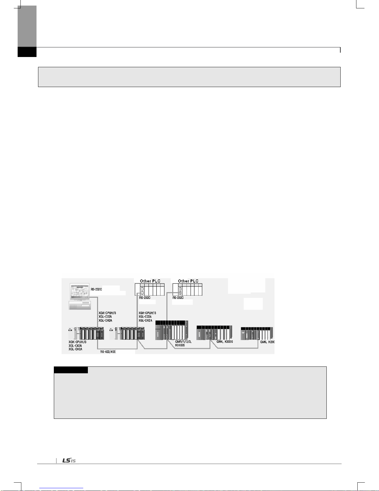
This user’s manual describes the Computer Link I/F module (hereinafter referred to as Cnet I/F module) of XGT PLC system
network. Cnet I/F module has the connection function with different model to communicate with communication devices of
various different type protocols such as other company’s PLC and computer, etc., and the function of modem communication to
control remote PLC.
When programming, refer to the following user manual.
• XG5000 manual
• XGK instruction
• XGK manual
• XGI/XGR instruction
• XGI instruction
• XGI manual
• XGR manual
When configuring the system of the XGT Cnet I/F module, be careful of the followings.
• XG5000: more than V4.0
• XGT Cnet I/F module OS: more than V2.3
Note
1) This manual is written on a basis of XG5000 V4.0
In case of previous version or different version, menu and method how to write a parameter may be different. Be
careful of this.
Chapter 1 Overview
1-2
1.2 Characteristics
The XGT Cnet I/F module is serial communication device supporting the RS-232C and RS-422(485) protocol and has the following
characteristics.
(1) Since the user can write directly, it is easy to connect with other company’s products
(2) Because communication speed and communication mode (protocol) are directly specified by user using XG5000 operative in
Windows environment, connection with other company’s products is easy.
(3) 3 types of Cnet I/F modules are available: RS-232C 2Port, RS-422(485) 2Port, RS-232C 1Port/ RS-422 1Port.
(4) With the separate operation based on each channel, the protocol data specified by user is controlled by CPU module, which
allows the replaced communication module directly to be applied without additional setting or downl oading.
(5) Read/Write is available by using the dedicated protocol.
(6) Dedicated communication function suitable to multi-drop configuration connectable up to 32 units is provided if RS-422/485
channel used.
(7) With modem communication function built-in, remote PLC can be controlled by XG5000 connection, dedicated communication,
and user defined communication.
(8) Various communication speeds can be set
- RS-232C : 300bps ~ 115,200bps / RS-422 : 300bps ~ 1 15,200bps.
(9) 1:1/1:N/N:M communication(if RS-422 channel used) is available.
(10) Communication types of full-duplex (RS-422/RS-232C) and half-duplex (RS-485) are supported.
(11) With satisfactory self-diagnosis function and Loop-Back diagnosis function, diagnosis of errors is easy to make.
(12) Dedicated communication and Modbus Server/Client functions are available.
(13) Remote connection during communication between XGT Cnet I/F modules is available.
Note1)
Note
Note1) Remote connection during communication between XGT Cnet I/F modules is supported when O/S version of
XGT Cnet I/F module is 2.5 or above. Features are as follows.
(1) For communication type, only RS-232C, RS-422 method is supported. In case of remote connection using
RS-485, remote connection is only available when the P2P link on the online menu of XG5000 is disabled.
(2) Remote connection is supported regardless of active mode.
(3) Remote connection during communication is affected according to TRX period and an amount of data
- In case TRX period is short or amount of data is huge, disconnection may occur.

Chapter 1 Overview
1-3
1.3 Product Configuration
1.3.1 Type name indication
Describes on the product configuration of the XGT Cnet module
Type name
Contents
Reference
XGL-C22A
RS-23 2C 2 ports
Twisted-pair shield cab le
XGL-CH2A
RS-23 2C 1 port, RS-422 1 port
XGL-C42A
RS-42 2 2 ports
1.3.2 Equip-able number per CPU
Note1)
The Cnet I/F module can be mounted up to 24 without distinction of basic and extension base. T o realize the
maximum capacity of communication module, if possible, mount the communication module in the basic base.
The following table indicates the available service type according to CPU. Apply it when configuring the system.
Classification
XGK XGI XGR
CPUH CPUU CPUA CPUS CPUE CPUU CPUH CPUS CPUH/T CPUH/F
Max. no. of module
using high speed
link
Not used
Max. no. of module
using P2P
8 EA
Max. no. of module
using dedicated
service
24 EA
Note
Note1) equipment position of Cnet I/F module according to CPU type
- In case of using XGK/XGI, Y ou can install Cnet I/F module at both basic and extension base.
- In case of using XGR CPU, You can install Cnet I/F module at only extension base.
Chapter 1 Overview
1-4
1.4 Soft ware to use the product
Here describe on main programming tool and other software to use the Cnet module. For more specific program
and application of communication, refer to the followings.
1.4.1 Sof tware check point
(1) A pplied at the XGT series
Classification
Connection port
Communication setting to ol
XGL-C22A
RS-23 2C 2 ports
XG5000
XGL-CH2A
RS-23 2C 1 port, RS-422 1 port
XGL-C42A
RS-42 2 2 ports
Note
1) The above program can be downloaded from our website now. In case of not using the internet, visit the near
our company and get the CD.
Internet web address : http://eng.lsis.biz
2) XG5000 is programmable through the RS-23C port of CPU module and USB. For the used cable name, refer
to the XGT catalog item list. (USB-301A, K1C-050A)
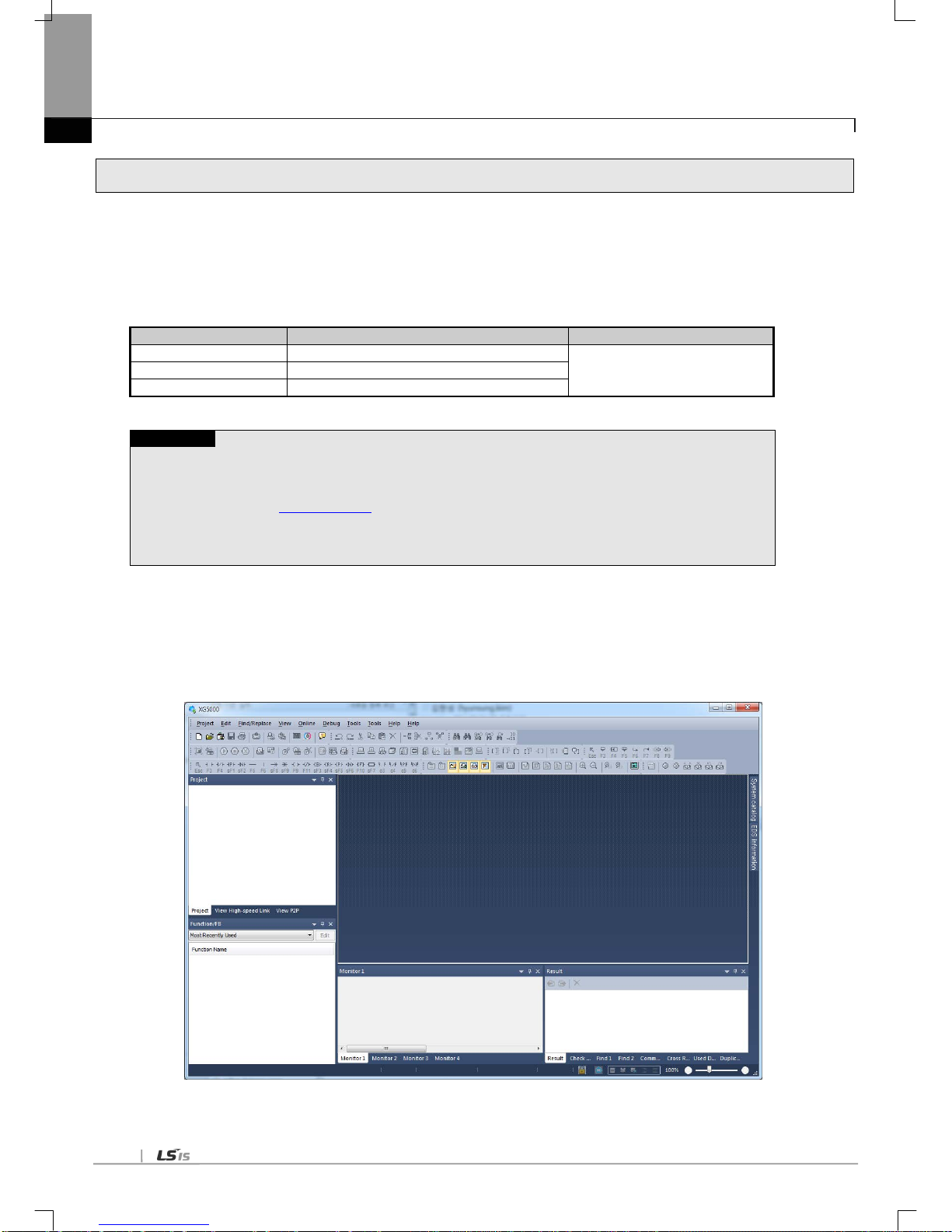
1.4.2 XG5000
XG5000 is dedicated software for setting of basic parameter, writing of frame and diagnosis of all communication
module including the Cnet I/F module.
The following figure is initial screen of XG5000.
[Figure 1.4.1] XG5000 initial screen
Chapter 1 Overview
1-5
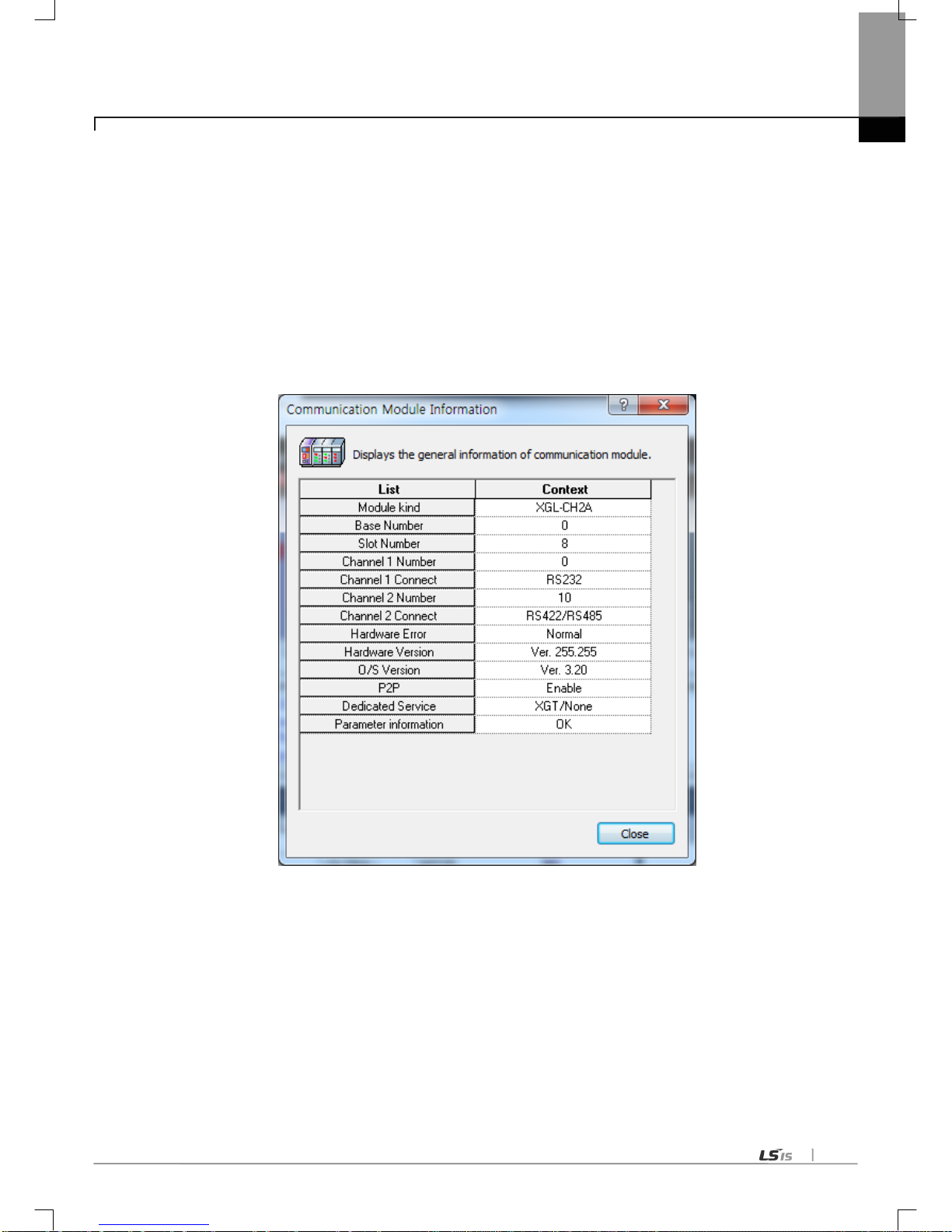
1.4.3 Check of version
Before using the Cnet module, check the version of module.
(1) Check through XG5000
Here describes on how to read communication module information by online connection to communication module. If
interface with CPU is normal, it is available to get the following information.
(a) Execute the XG5000.
(b) Connect with CPU through online connection.
(c) If connection with CPU is established, execute the system diagnosis.
(d) Execute the Communication module information in the system diagnosis screen.
(e) Software information shows at the right bottom of screen.
[Figure 1.4.2] Check of version through XG5000
(2) Check version written on the case label of the product
Each communication module has the product information label on the case. If online check is not possible, see
the label on the case after removing it from base.
Label is in the back of the case and type name of product and version information is indicated.

Chapter 2 Product Specifications
2-1
Chapter 2 Product Specifications
2.1 General Specifications
General specifications of XGT series are as follows.
No. Items Specification Reference
1
Ambient T emp.
0 ~ 55 °C
2 Storage T emp. −25 ~ +70 °C
3 Ambient humidity 5 ~ 95%RH (Non-condensing)
4
Storage humidity
5 ~ 95%RH (Non-condensing)
5 Vibration Immunity
Occasional vibration
- Frequency
Acceleration
Pulse width
Times
IEC61131-2
5≤f< 8.4
㎐
- 3.5mm
10 times each
direction (X,Y
and Z)
8.4≤f≤150
㎐
9.8㎨(1G) -
Continuous vibration
Frequency
Acceleration
Pulse width
5≤f< 8.4
㎐
- 1.75mm
8.4≤f≤150
㎐
4.9㎨(0.5G)
-
6 Shocks Immunity
• Peak acceleration : 147 m/s2(15G)
• Duration : 1 1ms
•
Pulse wave type : Half-sine (3 times each direction per each axis)
IEC61131-2
7 Noise Immunity
Square wave
impulse noise
AC : ±1,500V
DC : ±900V
LSIS internal test
spec.
Electrostatic
discharge
Voltage: 4kV (Contact discharge)
IEC61131-2
IEC61000-4-2
Radiated
electromagnetic field
noise
80 ~ 1000 MHz, 10V/m
IEC61131-2,
IEC61000-4-3
Fast transient
/Burst noise
Classificat
ion
Power
supply
Digital/Analog Input/Output,
Communication Interface
IEC61131-2
IEC61000-4-4
Voltage
2kV
1kV
8
Operation ambience
Free from corrosive gases and excessive dust
9 Altitude Less than 2,000m
10 Pollution degree Less than 2
11
Cooling method
Air-cooling
[T able 2.1] General Specifications
Note
1) IEC (International Electrotechnical Commission):
An international nongovernmental organization which promotes internationally cooperated standardization in
electric/electronic field, publishes i nternational stand ards and manages applicable estimation system re lated with.
2) Pollution degree:
An index indicating pollution degree of the operating env ironment which decides in sulation performance of the devices. For instance, Pollution
degree 2 indicates the state generally that only non-conductive pollution occurs. However , this state cont ains temporary conduction due to dew
produced.

Chapter 2 Product Specifications
2-2
2.2 Performance Specifications
Item
Specification
XGL-C22A
XGL-CH2A
XGL-C42A
Serial
communicat
-ion cha nnel
RS-232C
2 channels
1 channel
-
Conforms to RS-232C standard
Line config
1:1
RS-422/485
-
1 channel
2 channels
Conforms to RS-422/485 standards
Line config
1:1, 1:n, n:1, m:n
Modem connection function
Remote communication with external devices is
available vi a publ ic t elepho ne li ne by conne cting exter nal
modem to the module.
-
Operating
mode
(specified
per port)
P2P
Operated by communication client
Protocol client exclusively used for LSIS,
Modbus ASCII/RTU client
Use defined communication available
SEVER
Protocol server exclusively used for LSIS
Modbus ASCII/RTU sever
Data
type
Data Bit
7 or 8
Stop Bit
1 or 2
Parity
Even/Odd/None
Synchronization type
Asynchronous ty pe
Transmission speed (bps)
300/600/1200/2400/4800/7200/9600
/19200/38400/57600/64000/115200 bps available
Station No. setting
Setting range : 0-31
Max. station No. available : 32 stations
Transmission
distance
RS-232C: Max.15m (extendible if modem used)
-
-
RS-42 2: Max. 500 m
Diagnosis function
Checking available through LED and XG-PD diagnosis service
Loop-Back diagnosis
Current consumption
310mA
310mA
300mA
Weight
121g
119g
116g
[T able 2.2] Performance Specifications

Chapter 2 Product Specifications
2-3
2.3 Names of Parts
Names of parts are as follows;
[Fig. 2.3.1] Cnet I/F Module, Front
<Name of each part>
Name
Contents
①
LED
Refer to the LED details
②
RS-232C interface
RS-232C interface to communicate with other device through serial
③ RS-422/485 interface RS-422/485 interface to communicate with other device through serial
<LED details>
LED LED details LED status Details of LED status
RUN
Displays Cnet operation
status
On Operation normal
Off Cnet module abnormal
I/F
Displays interface status
with CPU
On
Operation abnormal during communication
with CPU module
Off
Communication module initializing error
Blinks
Operation normal
TX
Displays fra me being
transmitted
On Frame being transmitted
Off Frame transmitted completely
RX
Displays fra me being
received
On Frame being received
Off Frame received completely
ERR Displays frame error
On
Frame error
Off
Frame normal
①->
②->
③->
①->
②->
③->

Chapter 2 Product Specifications
2-4
2.4 Cable Specifications
When using communication channel, RS-422 or RS-485, twisted pair cable for RS-422 shall be used in consideration of
communication distance and speed. [Table 2.4] describes recommended specifications of cable. Also when using other cable
than recommended, the cable conforming to characteristics in [Table 2.4] shall be used.
(1) Product : Low Capacitance LAN Interface Cable
(2) Type : LIREV-AMESB
(3) Size : 2P X 22AWG(D/0.254 TA)
(4) Manufacturer: LS Cable
Electric
characteristics
T est item
Unit
Characteristics
T est conditions
Conductor resistance
Ω
/km
59 or less
Normal temp.
Withstanding voltage(DC)
V/1min
Withstands for 1 min. at
500V
In air
Insulation resistance
MΩ-km
1,000 or more
Normal temp
Static electricity capacity
pF/M
45 or less
1kHz
Characteristics
impedance
Ω 120 ± 12
10MHz
Characteristics of
appearance.
Item
Single Cable
Conductor
Cores
Pair 2 Size
AWG
22
Composition
NO./mm
1/0.643
Outer dia.
mm
0.643
Insulator
Thickness
mm
0.59
Outer dia.
mm
1.94
[T able 2.4.1] St andard of Tw isted Pair Cable
[Fig. 2.4.1] Structure
Braided
Ground line
AL/MYLER TAPE
Conductor
Insulator
Sheath

Chapter 2 Product Specifications
2-5
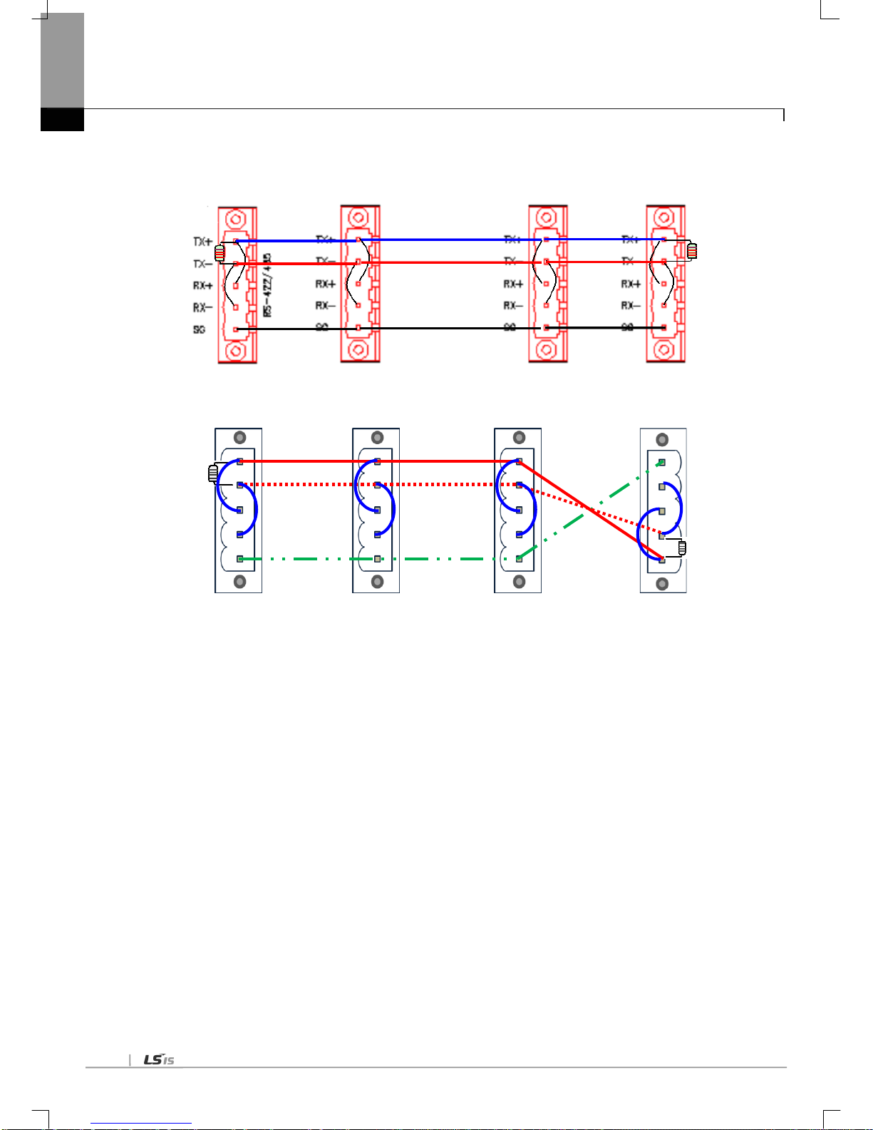
2.5 Terminal Resistance
For communication via RS-422/RS-485 channel, terminal resistance from external must be connected. Terminal resistance has the
function to prevent distortion of signal by reflected wave of cable for long-distance communication, and the same resistance (1/2W)
as characteristic impedance of cable must be connected to terminal of network.
When using the recommended cable in 2.4, connect terminal resistance of 120Ω to both ends of cable. Also when using other cable
than recommended, the same resistance (1/2W) as characteristic impedance of cable must be connected to both ends of cable.
▶ T erminal Resistance: 1/2W, 120Ω, tolerance of 5%
(1) How to connect with terminal resistance, When using RS-422 connection
[Fig. 2.5.1] RS-422 connection with Terminal Resistance
[Fig. 2.5.2] RS-422 connection with Ter minal Resistance by hardware version
TX+
TXRX+
RXSG
TX+
TXRX+
RXSG
TX+
TXRX+
RXSG
SG
RXRX+
TXTX+
(Less then V2.0) (Less then V2.0) (Less then V2.0) (V2.0 or Later)
Chapter 2 Product Specifications
2-6
(2) How to connect with terminal resistance during RS-485 connection
[Fig. 2.5.3] RS-485 connection with Ter minal Resistance
[Fig. 2.5.4] RS-485 connection with Ter minal Resistance by hardware version
TX+
TXRX+
RXSG
TX+
TXRX+
RXSG
TX+
TXRX+
RXSG
SG
RXRX+
TXTX+
(Less than V2.0) (Less than V2.0) (Less than V2.0) (V2.0 or Later)

Chapter 3 Performance Specifications
3-1
Chapter 3 Performance Specifications
3.1 Operation Mode Setting
The operation mode of XGT Cnet is decided by the basic communication parameters. It operates separately from each
communication port with the operation modes available as described below.
(1) Server Mode
Operates as a server in the network. XGT server and Modbus server are optional.
(a) XGT server: dedicated communication protocol supported, memory Read/Write available.
(b) Modbus server: Modbus protocol supported, RTU/ASCII type optional.
(c) Setting necessary for conversion between Modbus protocol memory area and XGT memory area.
(d) XG5000 service (remote 1/2 step connection) functions supported at a time.
(2) P2P (Client) Mode
(a) Operates as a client in the network.
(b) Dedicated communication protocol and Modbus protocol supported.
(c) Up to 64 communication blocks can be specified for 1 Cnet module to define the independent operation.
Chapter 3 Performance Specifications
3-2
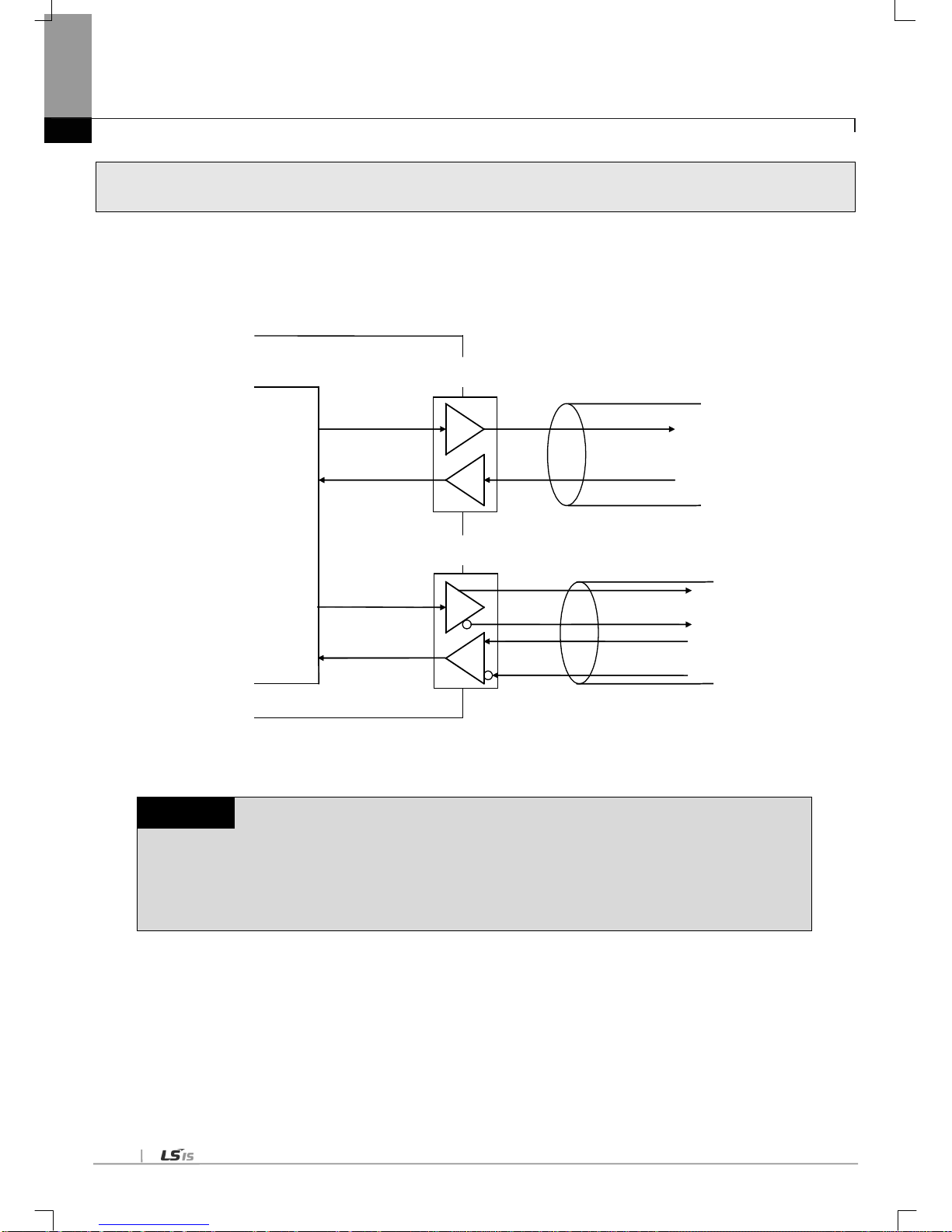
3.2 Channel Operation during Normal Run
Each communication port operates independently to allow simultaneous Tx/Rx in separate transmission specifications.
Therefore, transmission specifications can be set per RS-232C and RS-422 channel, and the operation is started and stopped
according to channels. Data flow of each channel is as below.
RS-422 channel
PLC CPU
TX
RX
RX
TX
RS-232C channel
RS-422 cable
RS-232C cable
[Fig. 3.2.1] Data Flow of Each Channel
Notes
[Note 1] Mode change during operation is unavailable. In order to change the mode, download the basic
communication parameters and reset the communication module.
[Note 2] Cnet I/F module supports only the separate mode.

Chapter 3 Performance Specifications
3-3
3.3 Channel Operation in Diagnosis Mode (Loop-Back)
Loop-Back diagnosis is a function to check if communication channel normally operates by itself without connection with
external devices, which is available when the diagnosis service is executed. For the details of its operation method, see
‘Chapter 11 Diagnosis Function’.
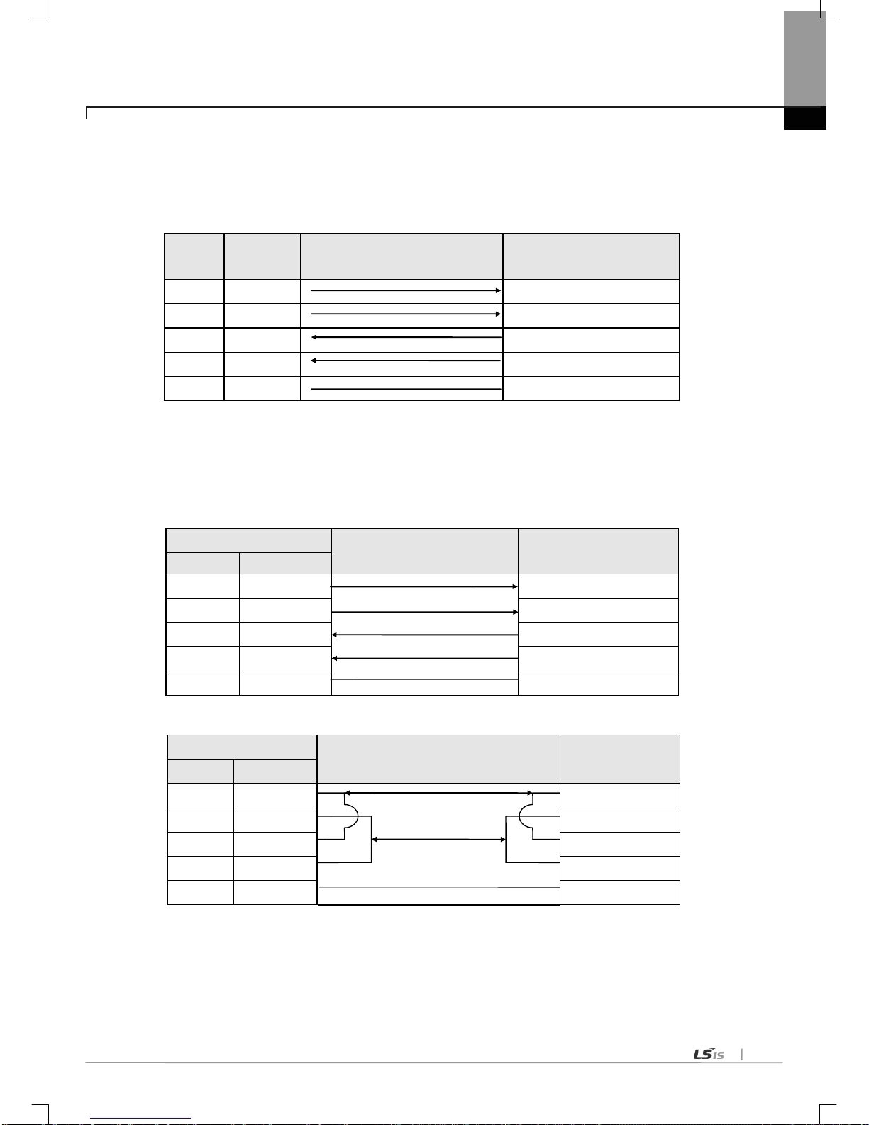
3.4 Method of Serial Interface
3.4.1 RS-232C I nterface
Channel RS-232C uses 9-pin connector (Female) for commun ic at io n with ex ternal devices. The n am es a nd f unc t io ns of pi ns
and dat a directi ons are as shown in the figure bel ow.
Pin No. Name Contents
Signal Direction
(Cnet I/F module
↔ external device)
Description
1
CD
Carrier Detect
Reports carrier detection of DCE to DTE
2
RxD
Received Data
Received data signal
3
TxD
Transmitted Data
Transmitted data signal
4 DTR
Data Terminal
Ready
Reports ready communication of DTE
Note1
to DCE
Note2
5
SG
Signal Ground
Ground line for signal
6
DSR
Data Set Ready
Reports ready communication of DCE to DTE
7
RTS
Request To Send
DTE asks DCE to send data
8
CTS
Clear To Send
DCE asks DTE to send data
9
RI
Ring Reports ringing tone received from DCE to DTE
[Fig. 3.4.1] RS-232C 9-pin Connector Standard
Channel RS-232C can communicate with external devices directly and also with remote communication devices using modem .
When connecting modem, communication type of RS-232C must be set to ‘modem’ with XG5000, and when not using modem,
it must be set to null modem
Notes
[Note1] DTE: Data Terminal Equipment (Cnet I/F module)
[Note2] DCE: Data Communication Equipment (external modem)
Chapter 3 Performance Specifications
3-4
(1) How to connect RS-232C connector during modem connection
This module can communicate with devices of long distance as connected with modem. Modem and RS-232C channel shall
be connected as in [Fig. 3.4.2] below.
Cnet (9-PIN)
Connection No. and signal direction
Modem side (25-PIN)
Pin No.
Name
Name
Pin No.
1
CD CD 8 2
RXD
RXD
3
3
TXD
TXD
2
4
DTR
DTR
20
5
SG
SG
7
6
DSR
DSR 6 7
RTS
RTS
4
8
CTS
CTS
5
9
RI
[Note]
RI
22
[Fig 3.4.2] Cable Connection between RS-232C and Mo dem
[Note] No.9, RI signal is not used in Cnet I/F module.
(2) How to connect connector for RS-232C in null modem mode
In null modem mode, the connector can be connected in 3-line type as below .
Cnet (9-PIN)
Connection No. and signal direction
Computer/communication
devices
Pin No.
Name
Name
1
CD CD
2
RXD
RXD
3
TXD
TXD
4
DTR
DTR
5
SG
SG
6
DSR
DSR
7
RTS
RTS
8
CTS
CTS
9
RI
RI
[Fig. 3.4.3] 3-line Type of Connection (no handshake)
Chapter 3 Performance Specifications
3-5
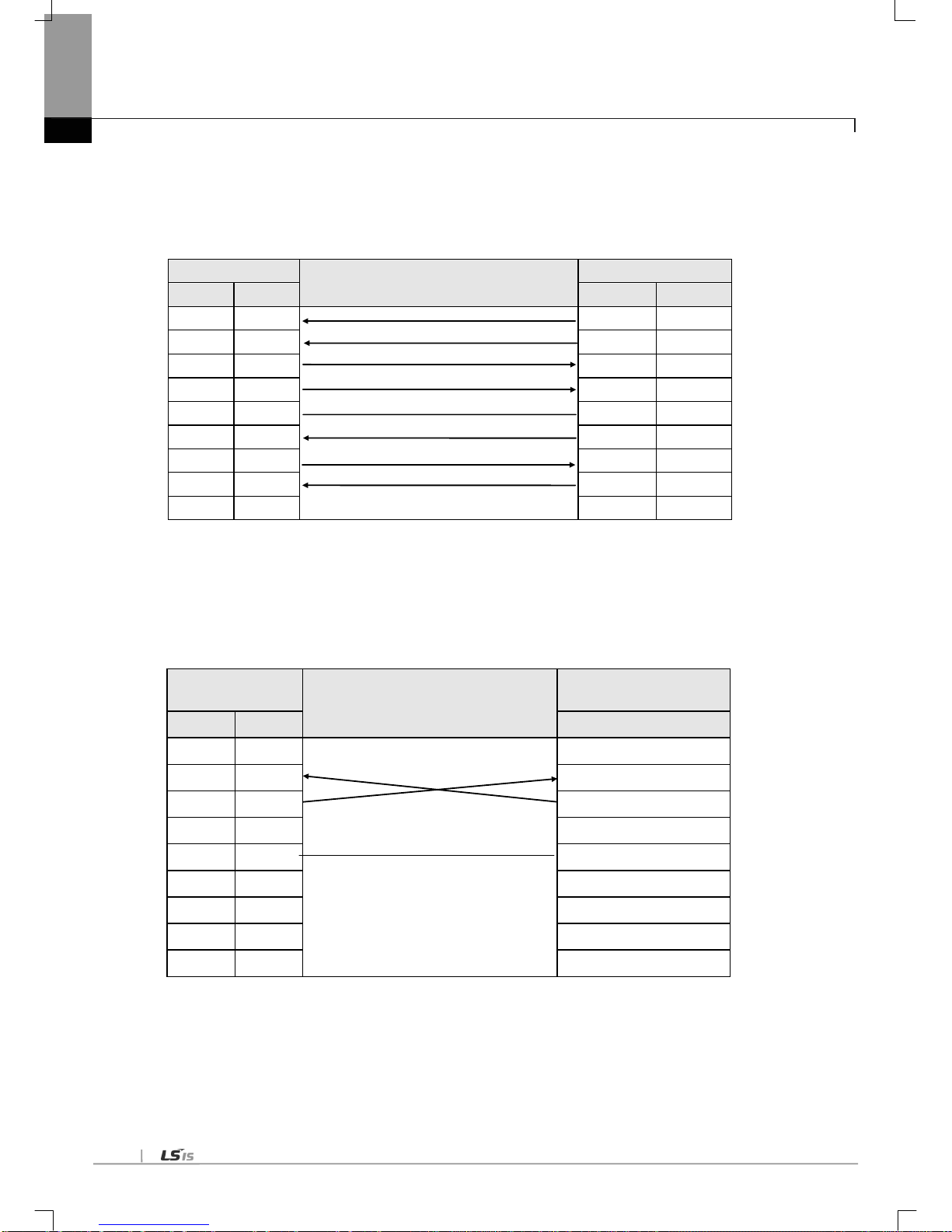
3.4.2 RS-422/485 interface
Channel RS-422 uses 5-pin connector (Terminal Block) for communication with external devices. The names and functions
of pins and data directions are as shown in [Fig. 3.5] below
Pin No. Name
Signal Direction
(Cnet<--> external device)
Description
1
TX+ Transmitted data (+)
2
TX- Transmitted data (-)
3
RX+ Received data (+)
4
RX- Received data (-)
5
S.G(SG)
Ground line for signal
[Fig. 3.4.4] RS-422 5-pin Connector Standard
Channel RS-422 is designed available to connect RS-422 and RS-485(multi-drop) with external devices. When RS-422
channel is used as multi-drop, set each channel’s communication type to RS-485 on the basic setting menu of XG5000, and
use the terminal of RS-422 connected as shown in [Fig. 3.7].
[Fig. 3.4.5] shows an example of connecting communication cable in RS-422 communication
Cnet(5-Pin)
Signal Direction
(Cnet<---> external device)
External communication
device
Pin No.
Name
1
TX+ RX+
2
TX-
RX-
3
RX+
TX+
4
RX-
TX-
5
S.G(SG)
S.G
[Fig. 3.4.5] RS-422 Connection
Cnet(5-Pin)
Signal Direction
(Cnet<---> external device)
External
communication device
Pin No.
Name
1
TX+ RX+
2
TX-
RX-
3
RX+
TX+
4
RX-
TX-
5
S.G(SG)
S.G
[Fig. 3.4.6] RS-485 Connection
[Fig. 3.4.6] shows how to connect RS-485 multi-drop communication. In case of multi-drop communication, to connect with
external devices, TX+ and RX+, RX- and TX- of RS-422 channel shall be connected with each other. At this time half-duplex
communication is run sharing Tx/Rx line, so the applicable port shall be applied as set to RS-485 in XG5000.

Chapter 4 Installation and Test O peration
4-1
Chapter 4 Installation and Test Operation
4.1 Installation Environment
This product is of high reliance reg ardless of insta llation environm ent. However, for the sake of relianc e and stabilit y of the
system, please pay attention to those precautions described below.
(1) Environmental Conditions
(a) To be installed on the control panel waterproof and dustproof.
(b) No continuous impact or vibration shall be expected.
(c) Not to be exposed to the direct sunlight.
(d) No dew shall be caused by rapid temperature change.
(e) Ambient temperature shall be kept 0-55 ℃.
(2) Installation Work
(a) No wiring waste is allowed inside PLC when wiring or drilling screw holes.
(b) To be installed on a good location to work on.
(c) Don’t let it installed on the same panel as a high-volta ge devic e is on.
(d) Let it kept at least 50 ㎜ away from duct or near-by module.
(e) To be grounded in an agreeable place free from noise.
Chapter 4 Installation and Test Operation
4-2
4.2 Precautions for Handling
The system configuration with Cnet I/F module shall be performed under the following precautions.
1) Don’t let it dropped or shocked hard.
2) Don’t remove PCB from the case. It will cause abnormal operation.
3) Don’t let any foreign materials including wiring waste inside the top of the module when wiring.
4) Get rid of foreign materials if any.
5) Don’t install or remove the mo dule whil e powered on.
6) Use standard cable only and let it installed within the maximum distance specified.
7) Let the communication cable free from the surge and inductive noise generated by or from the alternating current.
8) D on’t let wiring too clos e to hot device and m aterial or in direct c ontact with oil for lo ng, which will caus e damage or
abnormal operation due to short-circuit.
9) For wiring with pipes, the pipes need grounding.
Chapter 4 Installation and Test O peration
4-3
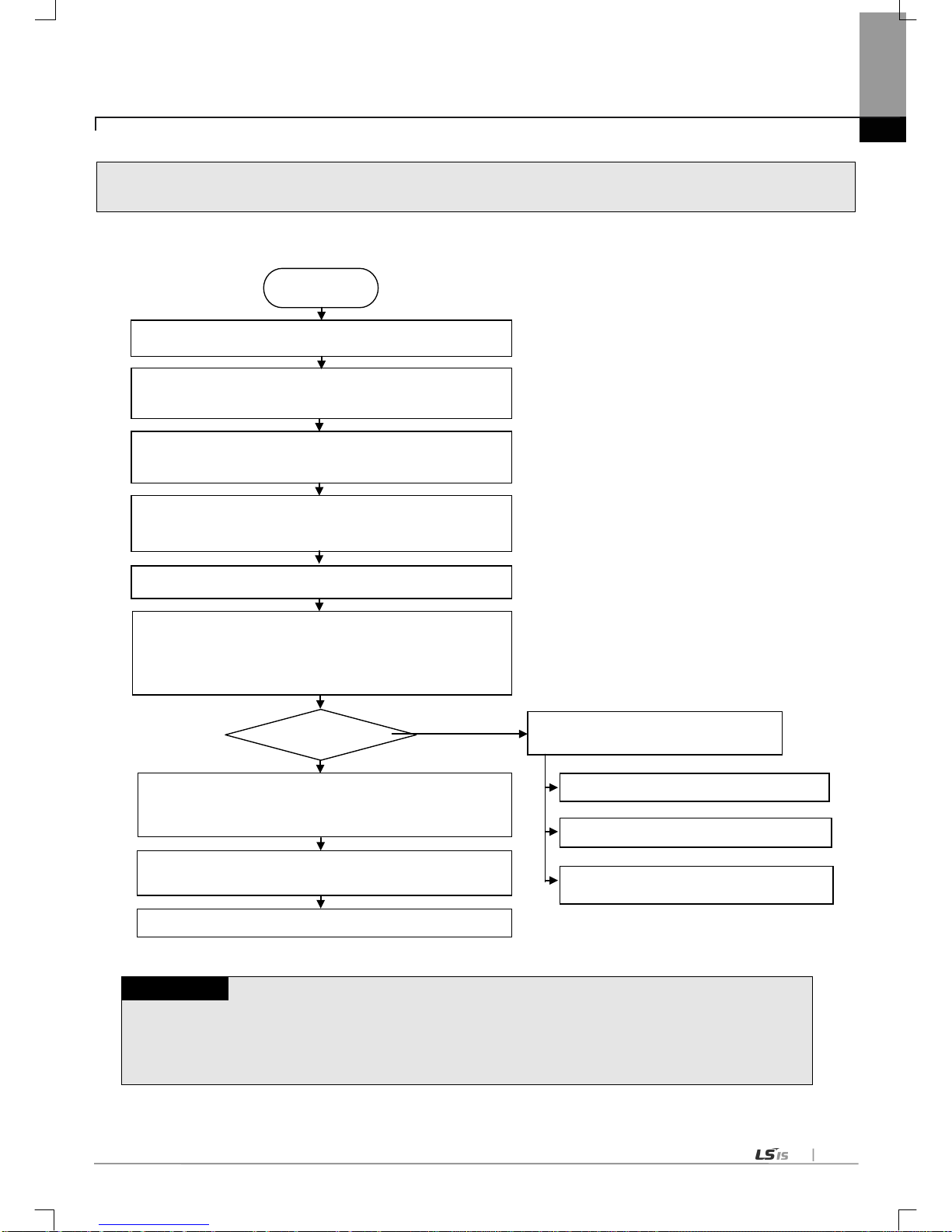
4.3 Operation Sequence
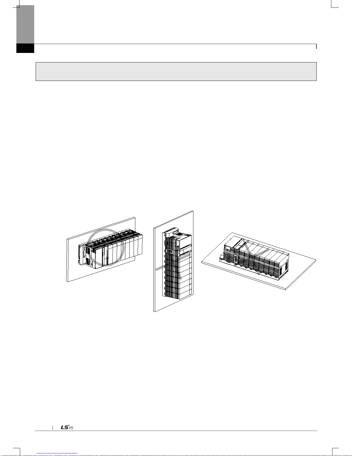
The sequence of t h e pro duc t fr om installation to operation will be described below. After the product installation is complete,
install and configure the system to be operated as specified in the following sequence.
Notes
1) Station number of Cnet I/F module is not necessary to set due to hardware properties.
Use XG5000 to specify basic settings necessary for station number and Cnet communication.
START
Check the function and specification
Install Cnet I/F module on the base.
→ Check the location of base/slot
Connect the communication device with Cnet I/F module by
means of cable.
With power On, check the LED status of the communication
module. (RUN: RED flicker, I/F: RED)
Connect XG5000 with XGK/XGI/XGR CPU by means of CPU
Perform basic setting in XG5000.
(communicatio n type, co mmunicat ion speed, data ty pe,
modem type, station number, operation mode)
Set the P2P parameter.
(channel, P2P function, start condition, data size, area, type,
destination st ation)
Execute the XGT server communication
Execute the modbus RTU server
Execute the modbus ASCII server
Execute the P 2P co mmunicati on
Operation
Download the parameter and let the link enabled.
Download the parameter and let the link
enabled.

Chapter 4 Installation and Test Operation
4-4
4.4 Contents of Parameter Setting in the XG5000
Contents of parameter setting in XG5000 are as follows.
4.4.1 Basic setting p arameter
Note
(1) Response waiting time: waiting time from sending to receiving
(a) Operation setting: Settable in case operation mode is Use P2P .
(b) basic response waiting time per communication speed
1) 9,600~115,200bps : 100ms+(setting value×100ms)
2) 7,200~2,400bps : 200ms+(setting value×100ms)
3) 1,800~1,200bps : 400ms+(setting value×100ms)
4) 600bps : 800ms+(setting value ×100ms)
5) 300bps : 1,200ms+(setting value×100ms)
(2) Delay time setting: sends frame after delay time set by user
(a) Operation setting: settable in case co mmunicati on type is RS-422/485
(3) Delay time between character: In case of character coming within set time at one frame, it means character
interval between character
(a) Operation setting: settable regardless of operation mode
Parameter
Lower
menu
Setting item Setting range
Setting right
Reference
Client Server
Basic
setting
Connection
setting
Communication type
RS-232C
RS-422
RS-485
○ ○
Communication
speed (bps)
300~1,15,200 ○ ○
Data bit 7,8 ○ ○
Modbus ASCII
In case of
modbus,
data bit is 7.
Stop bit
1,2 ○ ○
Parity bit
NONE,ODD,EVEN
○
○
Modem type
Null modem, dedicated
modem, dial up modem
○ ○
Modem initiali zation - ○ ○
Setting available in
case of dial up
modem
STATION 0~31 ○ ○
No meaning i n case
of client
Delay time
0~2550ms ○ -
Used in case of P2P
Time out 0~5000ms ○ - Used in case of P2P
Operation
mode
Use P2P settings
Select one mode
○
-
XGT server
-
○
Modbus ASCII server
-
○
Modbus RTU server
-
○

Chapter 4 Installation and Test O peration
4-5
4.4.2
P2P setting parameter
Parameter Lower menu Setting item
Setting range and
contents
Setting right (client)
XGT
Modbus
ASCII
Modbus
RTU
User
definition
frame
P2P
Communication
module setting
Base
0~7
○ ○ ○ ○ Slot
0~11
○ ○ ○
○
P2P channel P2P driver
User frame definition
- - -
○
XGT client
○ - -
-
Modbus ASCII
Client
- ○ - -
Modbus RTU
Client
- - ○
P2P block
Channel
1, 2
○ ○ ○
○
P2P function
READ
○ ○ ○ - WRITE
○ ○ ○
-
SEND
- - - ○ RECEIVE
- - -
○
Conditional flag
*note 1)
○ ○ ○
○
Command type
Single
○ ○ ○
-
Continuous
○ ○ ○
-
Data type
Bit
○ ○ ○
-
Word
○ ○ ○
-
1 byte
○ - -
-
2 byte ○ - - -
4 byte
○ - -
-
8 byte
○ - -
-
No. of variable
*note2)
○ ○ ○ - Data size
*note2)
○ ○ ○
-
Destination station
○ ○ ○
-
Destination station
no.
○ ○ ○ -
Frame
- - ○ Setting
*note3)
○ ○ ○
○
User definition
frame
Add group
Group name
- - -
Frame type
Transmission
- - -
○
reception - - - ○
Frame
*Note4)
Edit group
Group name
- - - ○ Delete group
- - -
○
Add frame
HEAD
- - - ○ TAIL
- - -
○
BODY
- - -
○
Note
1) Conditional flag can be set when P2P function is ‘SEND’ in case of user definition frame communication.
2) No. of variable and data size can be set when command type is ‘Continuous’ at the XGT client, Modbus ASCII/RTU
client.
3) Setting can be set when selecting the fix sized variable or variable sized variable in case of user definition frame
communication.
4) Frame setting is available after setting the group name and frame type of user definition frame.

Chapter 4 Installation and Test Operation
4-6
4.5 I/O Assignment and Device Information
4.5.1 I/O assignment
(1) When using the XGK CPU
(a) How to configure the basic system
The characteristic of basic system consisting of basic and extension base is as follows. The number of extension
base is different according t o CPU type and there a re fixed ty pe and changeable methods on I/ O assignment.
Classification XGK-CPUE XGK-CPUS XGK-CPUA XGK-CPUH XGK-CPUU
Max. extension no. 1 3 3 7 7
Max. equip-able
I/O module no.
24 48 48 96 96
Max. I/O point
1,536
3,072
3,072
6,144
6,144
Max. extension
distance
15m
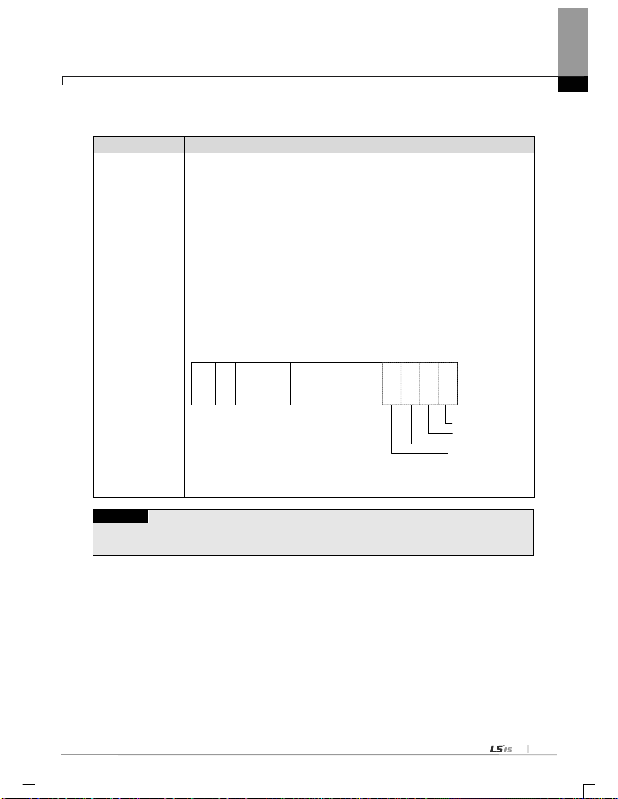
(b) Assignment of I/O point (fixed type)
1) 64 I/O points are assigned to each slot regardless of module.
2) 1024 (64*16) I/O points are assigned to each base. Namely no. 1 base’s start number is P00640. (Refer to
2.3.2)
3) The example of I/O assignment of 12 slot base is as follows.
0 1 2 3 4 5 6 7 8 9 10
11
(c) Assignment of I/O point (Changeable type)
1) The point changes according to each module equipped at the slot.
2) If there is no module, designated point is assigned.
3) The slot not designated by I/O parameter is assigned according to the equipped module automatically. (8 points
module is assigned as 16 points.)
4) The empty slot not designated by I/O parameter is assigned as 16 points.
5) It is possible to set the points without designation of module.
6) 16 points is assigned at the slot where special and communication module is equipped.
7) The example of assignment of I/O point for 12 sl ot base is as foll ows.
0 1 2 3 4 5 6 7 8 9 10
11
P
W
R
IO
1
6
IO
1
6
IO
3
2
IO
6
4
IO
1
6
IO
3
2
IO
3
2
IO
6
4
IO
3
2
IO
3
2
IO
1
6
IO
3
2
C
P
U
Slot no.
P
W
R
IO
1
6
IO
1
6
IO
3
2
IO
6
4
IO
1
6
IO
3
2
IO
3
2
IO
6
4
IO
3
2
IO
3
2
IO
1
6
IO
3
2
C
P
U
Slot no.
Chapter 4 Installation and Test O peration
4-7
(2) When using the XGI CPU
(a) How to configure the basic system
Classification XGI-CPUU XGI-CPUS XGI-CPUE
Max. extension no. 7 3 1
Max. equip-able IO
module no.
96 48 24
Max. IO points
• In case of 16 point s module: 1,536 point
• In case of 32 point s module: 3,072 point
• In case of 64 points module : 6,144 point
768 point
1,536 point
3,072 point
384 point
768 point
1,536 point
Max. extension
distance
15m
• IO number is a ssigned as 64 point per each slot by fixed type.
• 64 point is assigned to each slot regardless of module.
• No li mit to slot location and number of special module
• Fixed IO no. i s not assigned to special module unlike the digital IO.
• Special module is controlled by dedicated function block and memory is assigned automatically.
• IO assignment example of 12 Slot base is as follows.
Note
1) Basic base no. is fixed a s ‘0’ and extension b ase no. is flexible by the setting swit ch.
2) Module type set by I/O parameter should be same with module type really equipped.
%QX 0.11.0 ~ 31
%QX 0.10.0 ~ 31
%QX 0.9.0 ~ 15
%IX 0.8.0 ~ 31
Po
wer
IO
1
6
IO
1
6
IO
3
2
IO
6
4
IO
1
6
IO
3
2
IO
3
2
IO
6
4
IO
3
2
IO
3
2
IO
1
6
IO
3
2
C
P
U
Base no. 0
Slot
no.
0 1 2 3 4 5 6 7 8 9 10 11

Chapter 4 Installation and Test Operation
4-8
(3) When using the XGR CPU
(a) How to configure the basic system
Classification XGR-CPUU
Configuration of basic
base
• Install basic base of same configuration double
Max. extension base
• Available to install 1~31 extension bases
Max. equip-able IO
module no.
• Availabl e to install up to 372 at extension base
Max. IO points
• In case of 16 points module: 5,952 point
• In case of 32 points module: 11,904 point
•
In ca se of 64 points module: 23,808 point
Max. extension
distance
• Between base
- Optical: 2 ㎞
- Electricity: 100 m
• Total max. distance
- Optical: 64 ㎞(When configuring 31 extension bases)
- Electricity: 3.2 ㎞ (When configuring 31 extension bases)
IO number allocation of
extension base
• IO number start value o f each base is determined by base number set in extension drive module. (1~31)
• IO number in base is fixed as 64 per slot.
Each slot is allocated 64 points regardless of module equipment and ty pe
• Special module doe sn’t use IO number to control unlike digital IO module.
It uses U device and dedicated function block
• IO number allo cation of 12 slot base is as follows.
IO number of basic
base
• IO number doesn’t have meaning in basic base because only communication module can be equipped.
• Thought basic base doesn’t use IO number, it is allocated same with 12 slot extension base.
•
B ase number of basic base is 0 and it is positioned at the first o f IO number.
Note
(1) Redundant basic base is fix ed as ‘0’. In the e xtension base, there is switch to set base number.
(2) Redundant CPU can b e installed at basi c base.
(3) Redundant CPU is CPU module o ccupying two slots.
(4) In order to start, module type set by IO parameter should be sa me with real equipped module type.
(5) When remote connection by using Cnet I/F module, station nu mber of extension drive available to connection i s limited 1~15.
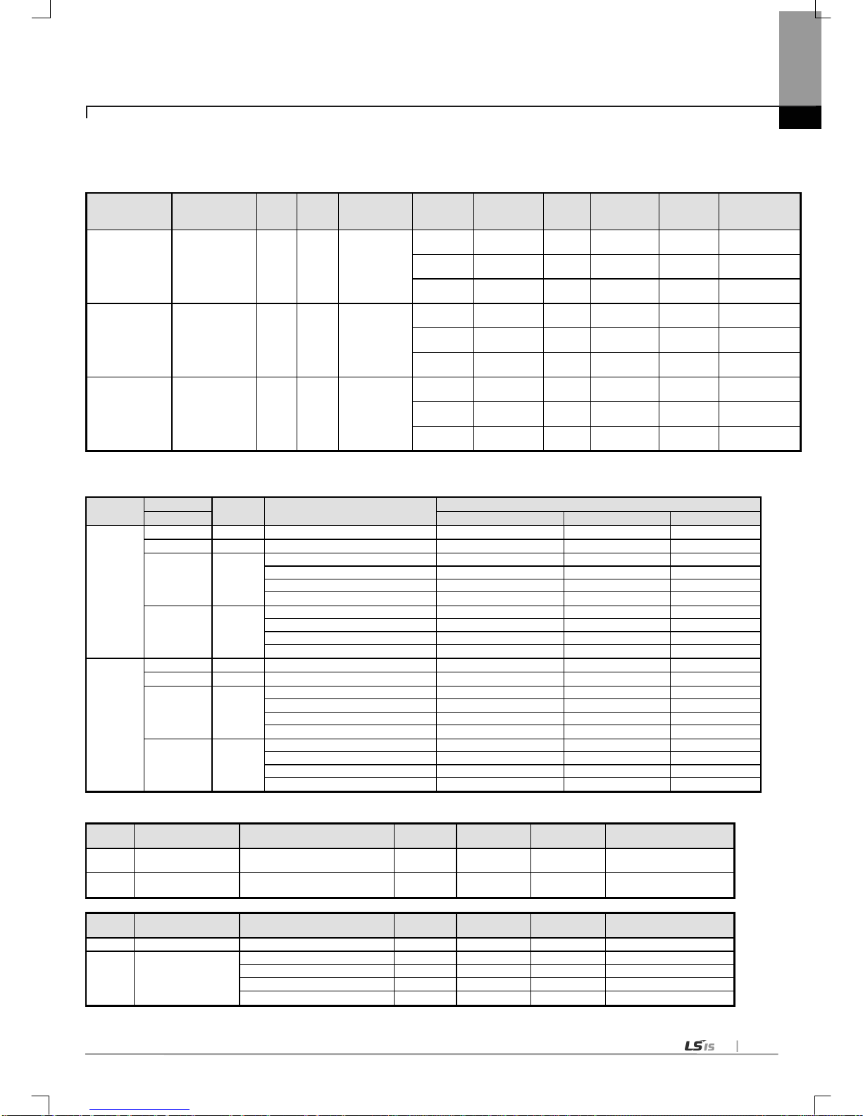
Chapter 4 Installation and Test O peration
4-9
4.5.2 Device information
(1) Basic setting
(2) Modbus setting
Channel
Modbus
Setting Items
Default per CPU
Use or not
XGK
XGI
XGR
Channel 1
Use P2P
Disable - - - -
XGT server
Disable - - - -
Modbus
ASCII server
Enable
Start address of Reading Bit:
P00000
%IX0.0.0
%IX0.0.0
Start address of Writing Bit:
P01000
%QX0.0.0
%QX0.0.0
Start address of Reading Word:
P0200
%MW0
%MW0
Start address of Writing Word:
P0300
%MW100
%MW100
Modbus
RTU server
Enable
Start address of Reading Bit:
P00000
%IX0.0.0
%IX0.0.0
Start address of Writing Bit:
P01000
%QX0.0.0
%QX0.0.0
Start address of Reading Word:
P0200
%MW0
%MW0
Start address of Writing Word:
P0300
%MW100
%MW100
Channel 2
Use P2P
Disable - - - -
XGT server
Disable - - - -
Modbus
ASCII server
Enable
Start address of Reading Bit:
P04000
%IX0.0.0
%IX0.0.0
Start address of Writing Bit:
P05000
%QX0.0.0
%QX0.0.0
Start address of Reading Word:
P0600
%MW0
%MW0
Start address of Writing Word:
P0700
%MW100
%MW100
Modbus
RTU server
Enable
Start address of Reading Bit:
P04000
%IX0.0.0
%IX0.0.0
Start address of Writing Bit:
P05000
%QX0.0.0
%QX0.0.0
Start address of Reading Word:
P0600
%MW0
%MW0
Start address of Writing Word:
P0700
%MW100
%MW100
(3) P2P channel setting
Channel Operation mode P2P driver TCP/UDP
Client/
Server
Partner port Partner IP address
1
Basic setting operation
mode
- - - - -
2
Basic setting operation
mode
- - - - -
Channel Operation mode P2P driver TCP/UDP
Client/
Server
Partner port Partner IP address
1
XGT server
-
- - -
-
2 Use P2P
XGT client
- - - - User definition frame
- - - - Modbus ASCII client
- - -
-
Modbus RTU client
- - -
-
Communication
type
Communication
speed
Data
bit
Stop
bit
Parity bit Model type
Modem
initialization
Station
no.
Response
waiting time
Delay time
Waiting time
between
character
RS-232C 300~115200 7~8 1~2 NONE~ODD
Null
modem
Disable 0~31
0~50 0~255 0~255
Dedicated
modem
Disable 0~31
0~50 0~255 0~255
Dial up
modem
Enable 0~31
0~50 0~255 0~255
RS-485 300~115200 7~8 1~2 NONE~ODD
Null
modem
Disable 0~31
0~50 0~255 0~255
Dedicated
modem
Disable 0~31
0~50 0~255 0~255
Dial up
modem
Disable 0~31
0~50 0~255 0~255
RS-422 300~115200 7~8 1~2 NONE~ODD
Null
modem
Disable 0~31
0~50 0~255 0~255
Dedicated
modem
Disable 0~31
0~50 0~255 0~255
Dial up
modem
Disable 0~31
0~50 0~255 0~255

Chapter 4 Installation and Test Operation
4-10
(4) P2P block setting
Operational
mode
P2P
driver
P2P
function
Conditi
onal
flag
Command
type
Data type
No. of
variable
Data size
Destination
no.
Read
area
Save
area
address
XGT server
- - - - - - - - - - -
Use P2P
XGT
Client
Read
XGT
device
Single
BIT
1 ~ 4
Disable
0~32
XGT
device
XGT
device
How to
calculate
the N
device
Single
1/2/4/8 (XGK)
B/W/D/L (XGI)
1 ~ 4
Continuous
1/2/4/8 (XGK)
B/W/D/L (XGI)
Disable
(1)
1 ~ 120
Write
Single
BIT
1 ~ 4
Disable
Single
1/2/4/8 (XGK)
B/W/D/L (XGI)
1 ~ 4
Continuous
1/2/4/8 (XGK)
B/W/D/L (XGI)
Disable(1)
1 ~ 120
Modbus
ASCII
client
Read
Single BIT
Disable
00000 ~
19999
Single WORD
30000 ~
49999
Continuous BIT 1 ~ 976
00000 ~
19999
Continuous WORD 1 ~ 61
30000 ~
49999
Write
Single BIT
Disable
XGT
device
00000 ~
09999
Single WORD
40000 ~
49999
Continuous BIT 1~944
00000 ~
09999
Continuous WORD 1~59
40000 ~
49999
Modbus
RTU
client
Read
Single BIT
Disable
00000 ~
19999
XGT
device
Single WORD
30000 ~
49999
Continuous BIT 1 ~ 2000
00000 ~
19999
Continuous WORD 1 ~ 125
30000 ~
49999
Write
Single BIT
Disable
XGT
device
00000 ~
09999
Single WORD
40000 ~
49999
Continuous BIT 1~1968
00000 ~
09999
Continuous WORD 1~123
40000 ~
49999
User
definition
frame
SEND Send body - - 1 ~ 1024
XGT
device
variable
sized
variable
-
RECEIVE - Receive body - - - -
Memory
designati
on
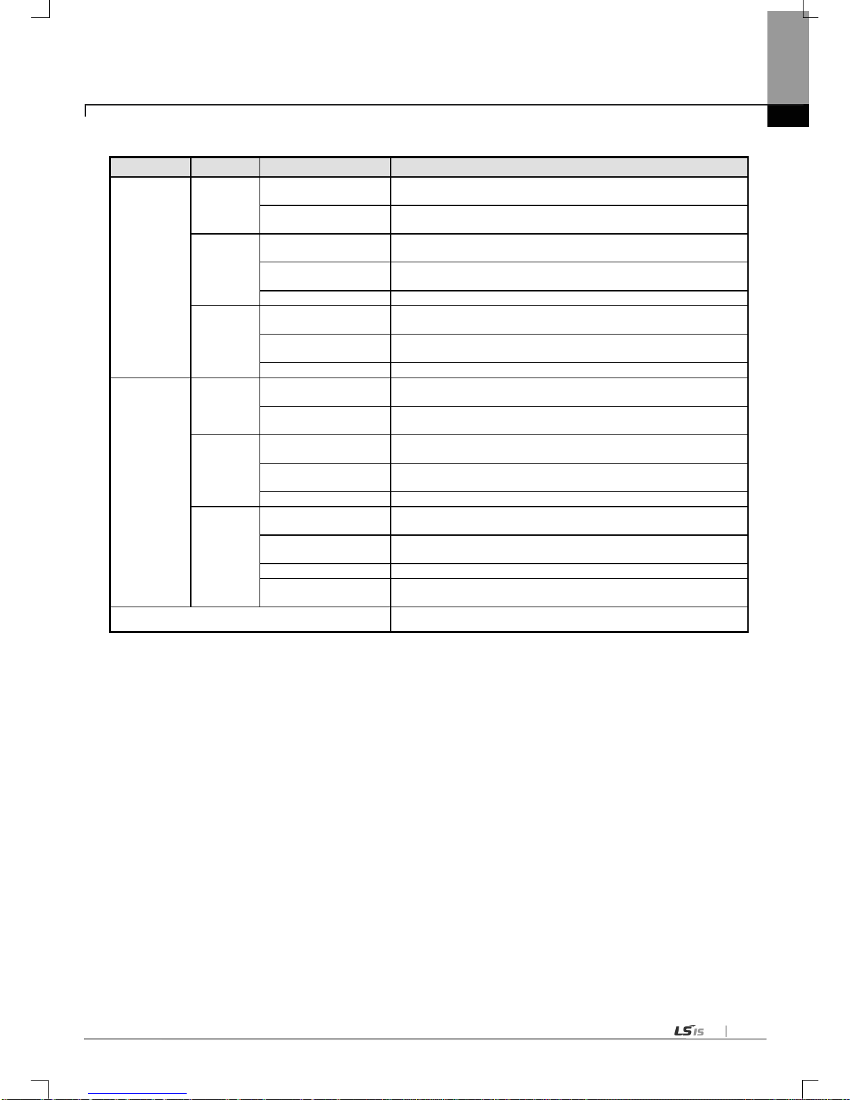
Chapter 4 Installation and Test O peration
4-11
(5) User definition frame
Group Frame Segment Reference
Transmission 1
HEAD
Numerical constant
Max. 10Byte
12345678901234567890
String constant
1234567890
(Saved as 3132..30)
TAIL
Numerical constant
Max. 10Byte
12345678901234567890
String constant
1234567890
(Saved as 3132..30)
BCC
-
BODY
Numerical constant
Max. 10Byte
12345678901234567890
String constant
1234567890
(Saved as 3132..30)
Variable sized variable
Up to 4
Reception 1
HEAD
Numerical constant
Max. 10Byte
12345678901234567890
String constant
1234567890
(Saved as 3132..30)
TAIL
Numerical constant
Max. 10Byte
12345678901234567890
String constant
1234567890
(Saved as 3132..30)
BCC
-
BODY
Numerical constant
Max. 10Byte
12345678901234567890
String constant
1234567890
(Saved as 3132..30)
Fix sized variable
Up to 4
Variable sized variable
It is available to set only one variable sized variable. So it is impossible to add segment
after variable sized variable
There is no number limit to group, frame, segment but size
(0x4B00).

Chapter 4 Installation and Test Operation
4-12
4.5.3 Available device area per CPU series
CPU
type
Area Range Size (word) Reference
XGK
P
P0~P2047
2048
Read/Write/Monitor available
M
M0~M2047
2048
Read/Write/Monitor available
K
K0~K2047
2048
Read/Write/Monitor available
F F0~F2047 2048
Read/Monitor available
(Write: available from 1025 word)
T
T0~T2047
2048
Read/Write/Monitor available
C
C0~2047
2048
Read/Write/Monitor available
L
L0~L11263
11264
Read/Write/Monitor available
N
N0~N21503
21504
Read/Write/Monitor available
D
D0~D32767
32768
Read/Write/Monitor available, XGK–CPUH
D0~D19999
20000
Read/Write/Monitor available, XGK–CPUS
R
R0~R32767
32768
Read/Write/Monitor available
ZR
ZR0~ZR65535
65536
Read/Write/Monitor available
XGI
I
IW0.0.0~IW127.15.3
8192
Read/Write/Monitor available
Q
QW0.0.0~QW127.15.3
8192
Read/Write/Monitor available
M
MW0~MW131071
131072
Read/Write/Monitor available
R
RW0~RW32767
32768
Read/Write/Monitor available
W
WW0~WW65535
65536
Read/Write/Monitor available
XGR
I
IW0.0.0~IW127.15.3
8192
Read/Write/Monitor available
Q
QW0.0.0~QW127.15.3
8192
Read/Write/Monitor available
M
MW0~MW131071
131072
Read/Write/Monitor available
R
RW0~RW32767
32768
Read/Write/Monitor available
W
WW0~WW65535
65536
Read/Write/Monitor available
Common U U0~U4095
4096
Monitor available
Note
(1) ZR devic e is avail able o nly at XGK -CPUH.
(2) ZR device should request by using “W”.
Ex) When requesting word size from ZR0, you should request as “%WW000”.
(3) A t U device, address of bit monitoring is hexadecimal and monitoring address of word area is decimal.

Chapter 5 System Configuration
5-1
Chapter 5 System Configuration
Cnet I/F module is used for CPUH and CPUS both. Up to 24 modules can be mounted on the main and expansion bases, and all
24 modules can be used using a dedicated protocol. However, only 8 modules are available to use P2P service.
Various communication systems can be configured via this module in accordance with application fields. This chapter describes
examples of
system configurations which are available or unavailable for the application fields.
5.1 Available System Configurations
5.1.1 1:1 connection (no modem) to PC (HMI)
PC(HMI) and Cnet I/F module are connected via RS-232C or RS-422 channel in 1:1 connection system with PC (HMI) or
PLC not through modem. Most PC(HMI)s are operated as client stations and Cnet I/F modules are operated as sever
stations that respond the request of PC(HMI). Since no modem is applied, communication distance is max.15m via RS-232C
channel and max.500m via RS-422 channel. Operation mode of Cnet I/F module shall be set as agreed with communication
type of PC(HMI).
[Fig. 5.1.1] 1:1 communication system with PC
5.1.2 1:1 dedicated modem connection to PC (HMI)
PC(HMI) and the module are connected through dedicated modem via RS-232C channel in 1:1 connection system. Most
PC(HMI)s are operated as client stations and Cnet I/F modules are operated as sever stations that respond the request of
PC(HMI). Since modem is applied to go through, RS-232C channel shall be set to dedicat ed mode m for long-distance
communication. Operation mode of this module shall be set as agreed with communication type of PC(HMI).
[Fig. 5.1.2] D
edicated modem communication wi th PC

Chapter 5 System Configuration
5-2
5.1.3 Modem connection to PC & Communication between Cnet I/F modules
(1) PC and Cnet #1 station are connected through modem via RS-232C channel.
(2) Cnet #1 station ~ N station carry out communication between Cnet I/F modules via RS-422 channel.
(3) PC is operated as client station of Cnet #1 station.
(4) Cnet I/F module can connect with max. 32 stations (RS-422/485 communication).
(5) RS-232C cha nnel of Cnet I/F module is set to sever station and RS-422 channel of Cnet I/F module is set to client station.
(6) Dedicated modem or dial-up modem is available to use.
[Fig. 5.1.3] Dedicated modem communication with PC
Type
Module setting
RS-232C RS-422 Station No.
PLC Cnet #1 station XGT Server
P2P
1
XGT Client
Cnet #2~#31 sta tion
Not used
XGT Server
2~31
[Table 5.1.1] Module Setting Table for Station No.
#0

Chapter 5 System Configuration
5-3
5.1.4 Dedicated communi cation with PC (HMI) & Other company’s RS-422 communicatio n
(1) Null-modem communication with PC (HMI) via RS-232C channel is available.
(2) PC (HMI) is operated as client station and Cnet I/F module RS-232C channel is operated as XGT server.
(3) Cnet I/F module RS-422 channel is operated in P2P mode.
(4) Display data i s tra nsmitt ed to displ ay modules of mosaic panel via Cnet RS-422 channel.
(5) Display transmission data can be read in PC.
[Fig. 5.1.4] 7-Segment Operation system for RS-422
Type
Module setting
RS-232C
RS-422
Station No.
PLC Cnet #1 station
XGT Server
P2P
1
[Table 5.1.2] Module Setting Table for Station No
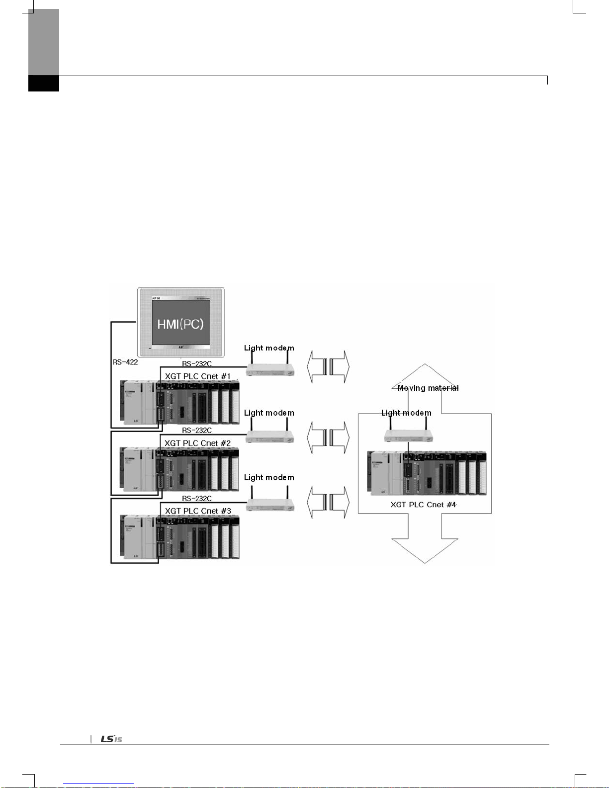
Chapter 5 System Configuration
5-4
5.1.5 Optical modem communication for mobile communication
(1) Optical modem communication system for Cnet communication on body in lineal motion.
(2) Dedicated mode communication or P2P communication with monitoring device.
(3) RS -232C/RS-422 commun ication wi th optic al mode m.
(4) Dedicated client/sever communication between Cnet I/F modules.
(5) Optical modem connected with Cnet I/F module on mobile body can communicate with the other
optical modem only when pos itioned in communi cation available
(6) Main application: Parking tower
[Fig. 5.1.5] Optical modem communication system

Chapter 5 System Configuration
5-5
5.1.6 Wireless modem communication for communication between revolution bodies
(1) Wireless modem communication system for Cnet communication on body in revolution motion.
(2) RS-232C communication with wireless modem.
(3) Dedicated client/sever communication between Cnet I/F modules.
(4) RS-232C channel of Cnet I/F module is dedicated modem mode.
[Fig. 5.1.6] Wireless modem communication system
Type
Module setting
RS-232C
RS-422
Station No.
XGL-CH2A
Dedicated mode
Not used 1 & 2
User mode
[Table 5.1.3] Setting details between communication modules

Chapter 5 System Configuration
5-6
5.1.7 TM/TC communication sy stem
(1) Long-distance communication with remote sever PLC via dedicated modem.
(2) Dedicated modem communication via RS-232C channel set to dedicated modem mode.
(3) Dedicated client/sever communication between Cnet I/F modules.
(4) 8 Cnet I/F modules can be mounted on TM client PLC.
[Fig. 5.1.7] TM/TC dedicated modem system
Dedicated modem Dedicated modem Dedicated modem Dedicated modem Dedicated modem Dedicated modem Dedicated modem Dedicated modem
Dedicated modem Dedicated modem Dedicated modem Dedicated modem Dedicated modem Dedicated modem Dedicated modem Dedicated modem

Chapter 5 System Configuration
5-7
5.2 Unavailable System Configurations
5.2.1 Dial-up modem communication between Cnet I/F modules(on condition)
(1) Cnet I/F module has no function to make telephone calls.
(2) Cnet I/F module has only function to answer telephone calls.
(3) Dial-up modem communication between Cnet I/F modules is unavai labl e.
If using ‘UDATA’ at program, communication is available.(Please, Refer to the CH10.6)
[Fig. 5.2.1] Dial-up modem communication between Cnet I/F modules
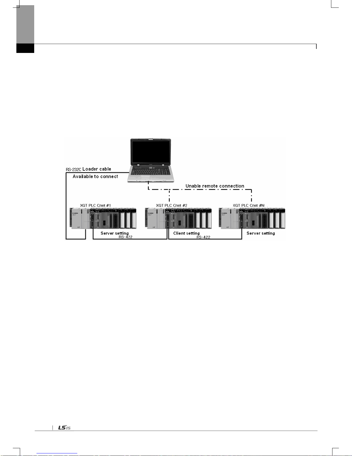
Chapter 5 System Configuration
5-8
5.2.2 XG5000 connection usin g RS-422 channel of Cnet I/F module
(1) XG5000 service of Cnet I/F module supports only RS-232C channel.
(2) XG5000 connection via RS-422 cha nnel is unav ailable .
(3) Setting of Cnet’s station number in XG5000 remote connection is unavailable.
(4) XG5000 connection i s availa ble only for Cnet #1 st ation as s hown in [Fig. 5.2.2].
[Fig. 5.2.2] XG5000 connection via RS-422 channel
XG5000

Chapter 6 Communication Parameter
6-1
Chapter 6 Communication Parameter
6.1 General
Communication parameter is classified into basic setting parameter and P2P setting parameter.
6.1.1 Basic set ting p arameter
Here sets the media information, H/W information and basic protocol information.
Note
(1) Response waiting time: waiting time from sending to receiving
(a) Operation setting: Settable in case operation mode is Use P2 P.
(b) basic response waiting time per communication speed
1) 9,600~115,200bps : 100ms+(setting value×100ms)
2) 7,200~2,400bps : 200ms+(setting value×100ms)
3) 1,800~1,200 bps : 400 ms+(set ting value ×100ms)
4) 600bps : 800ms+(setting value×100ms)
5) 300bps : 1,200ms+(setting value×100ms)
(2) Delay time setting: sends frame after delay time set by user
(a) Operation setting: settable in case communication type is RS-422/485
(3) Delay time between character: In case of character coming within set time at one frame, it means character interval
between character
(a) Operation setting: settable regardless of operation mode
(4) IGNORE: If the parity bit error occurred, data can be received
- Cnet: V3.1, XG5000: V4.0 or later
Parameter
Lower
menu
Setting item Setting range
Setting authority
Contents
Client
Server
Basic
setting
Connection
setting
Communication type
RS-232C
RS-422
RS-485
○ ○
Interface setting
Communication speed (bps)
300~115,200
○
○
Communication speed setting
Data bit
7,8 ○ ○
Frame structure
definition
Stop bit
1,2
○
○
Parity bit
NONE,ODD,EVEN
○
○
Modem type
Null modem
Dedicated modem
Dial up modem
○ ○
Setting related with modem
Modem initiali zation
-
○
○
STATION NO.
0~31
○
○
Communication statio n no. setti ng
Response waiting time
0~50
○
-
Delay time setting
0~255
○
○
Delay time between character
0~255
○
-
Operation
mode
Use P2P
Select one
○
-
Communication method setting
XGT server
-
○
Modbus ASCII server
-
○
Modbus RTU server
-
○

Chapter 6 Communication Parameter
6-2
(1) P2P service
(a) The Cnet I/F module operates as a client in the network.
(b) When the designated event occurs, it is available to read or write the meory.
(It can operate as XGT client and modbus client.)
(c) It is used to communicate with other device that doesn’t support the XGT or modbus protocol or send/receive
the user definition frame.
(d) It is available to define max. 64 P2P blocks per each channel.
(2) Dedicated service (XGT server, modbus ASCII server, modbus RTU server)
(a) It is a vaila ble t o writ e/read the info rmation without specific program.
(b) It can operate as XGT server that supports the XGT protocol and modbus server that supports the RTU/ASCII
protocol.
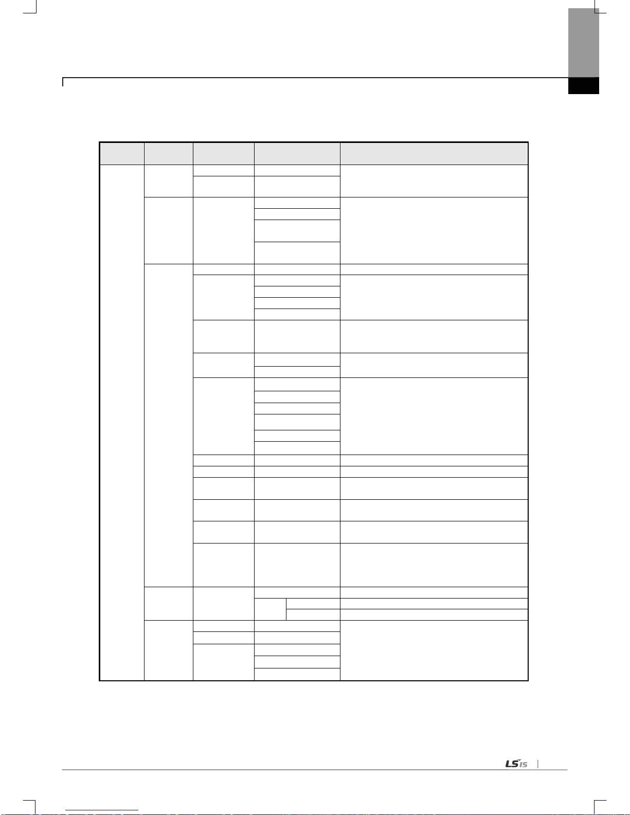
Chapter 6 Communication Parameter
6-3
6.1.2 P2P setting p aramet er
This sets the communication frame.
Parameter
Lower
menu
Setting item Setting range Contents
P2P
Communica
tion module
setting
Base
0~7(0~31:XGR)
Set the location of module
Slot 0~11
P2P
channel
P2P driver
User frame definition
Communication method setting
XGT client
Modbus ASCII
Client
Modbus RTU
Client
P2P block
Channel
1, 2
Communication port setting
P2P function
READ
Data Sending/Receving setting
(SEND, RECEIVE
is used in the user definit ion
frame.)
WRITE
SEND
RECEIVE
Conditional flag -
Sets the operation condition of frame
(Conditional
flag can be set when P2P function is
SEND in case of user definition frame.)
Command type
Single
Sets the sending method
Continuous
Data ty pe
BIT
Sets the data unit of frame
WORD
1 BYTE
2 BYTE
4 BYTE
8 BYTE
No. of variable
-
Sets the no. of variable in the frame
Data size
Sets the data size in the frame
Destination
station
When destination station is necessary.
Destination
station no.
Sets the destination station no.
Frame
Sets the body name in case of user definition
frame communication
Setting
In case of user def inition frame communication,
Setting item can be set when variable sized
variable or fix sized variable is selected in the
frame body.
User
definition
frame
Add group
Group name
Sets the frame group name
Frame
type
Transmission
Sets the frame related with transmission
Reception
Sets the frame related with reception
Frame
Edit group
Group name
Frame setting is available after sett ing the group
name and frame type.
Delete group
Add frame
HEAD
TAIL
BODY

Chapter 6 Communication Parameter
6-4
6.2 T ransmission S t andard
In order to use the Cnet I/F module, set the transmission standard like baud rate, data/stop bit. The basic setting
item of Cnet I/F module should be same with transmission standard of system. The written contents are saved in the
CPU module of PLC, those are kept regardless of power supply unit the user write new one.
6.2.1 Setting item
Setting item of Cnet is shown in [Table 6.2.1].
Item Setting value Default Reference
Communication type RS-232C / RS -422 / RS-485 RS-232C Setting is essential
Baud rate (bps)
300/600/1,200/1,800/2,400/3,600/4,800/7,200
/9,600/19,200/38,400/57,600/64,000/115,200
9,600
Data
type
Data bit 7/8 8
Stop bit 1/2 1
Parity bit None/Even/Odd/Ignore None Check specific information
Modem type Null modem / dedicated modem / dial up modem Null modem
Dedicated service
driver
XGT dedicated XGT server
XGT server
(XGT
dedicated
communication)
Check specific information
Modbus
RTU/ASCII server
Bit read/write area
Word read/write area
Station number 0 ~ 31 0
Commonly used to all
services
[Table 6.2.1] Cnet basic setting item
Since the Cnet I/F module provides two communication channels, Cnet basic setting is necessary for each cannel.
According to communication module, RS-232C 2 ports, RS-232C 1port/RS-422 1 port, RS-422 2 ports is pr ovided.
Additional information of some items in [T able 6.2.1] is as follows.

Chapter 6 Communication Parameter
6-5
(1) Communication type
Check the Cnet I/F module and set the parameter about each channel accurately. If communica tion ty pe set
by parameter is different with channel ty pe of real co mmunicati on module, normal communication is
impossible because CPU recognizes th e channel ty pe of real communication module.
(a) Parity bit
The Cnet I/F module defines three parity bit. Each parity bit has the following meaning like [Table 6.2.2].
Parity Meaning reference
None Not use parity bit
Even If the number of 1 is even in the one byte, it sends 0 at the parity bit.
Odd If the number of 1 is odd in the one byte, it sends 0 at the parity bit.
[Table 6.2.2] Parity content
(b) Dedicated service driver
The user can select the operation mode about each channel of Cnet I/F module by using the driver selection
item.
Each channel of Cnet I/F module operates as server or client, each channel operates independently.
Type and meaning of operation mode for each channel is as following [Table 6.2.3].
Driver type Meaning Reference
P2P
Relevant port acts as client and it communicates by P2P
parameter setting.
Refer to P2P
setting
XGT server
Supports the XGT dedicated communication and acts as
XGT server.
For dedicated
service
Modbus ASCII server Acts as modbus ASCII server
Modus RTU server Acts as modbus RTU server
[Table 6.2.3] Driver type and meaning
If operation mode of Cnet channel is XGT server or modbus, it supports the loader service with the dedicated
service.
1) XGT server
Supports readi ng/writi ng memo ry of the dedicated service
2) Modbus ASCII/RTU server
a) This is used when network is configured with modbus protocol and Cnet I/F module acts as server.
b) Since modbus memory area is different with XGT memory area, memory mapping is necessary.
c) For memory mapping, refer to the “Chapter 7.1”
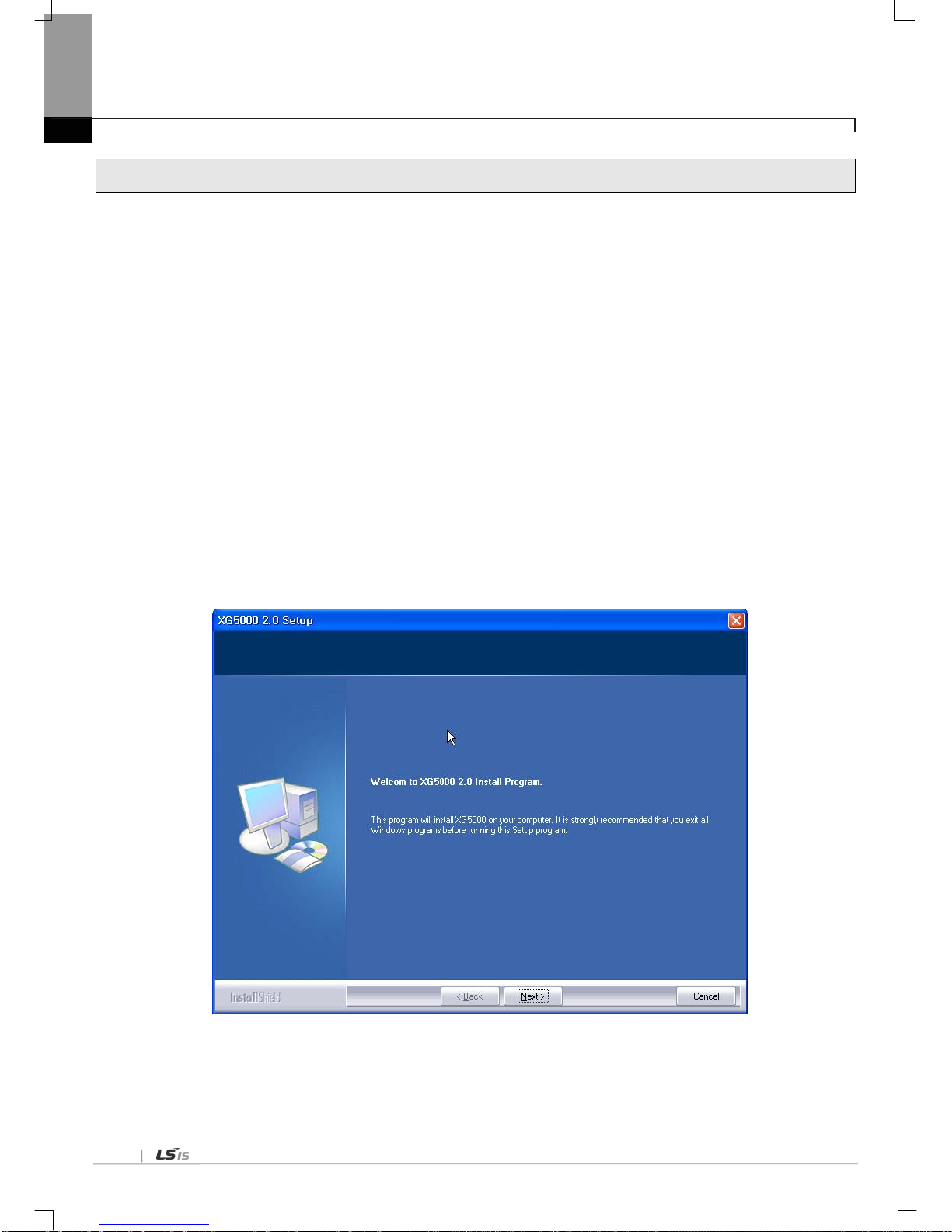
Chapter 6 Communication Parameter
6-6
6.3 Installation and Execution of Software
T o use the XG5000 software, the user should install the XG5000.
System requirement for execution is as follows.
(1) PC and memory
More than Pentium CPU and 128MB memory
(2) Communication port
RS-232C serial port and USB port is necessary.
(3) Hard disk
More than 100MB
(4) Mouse
Mouse connect-able with computer
(5) Monitor
Resolution is more than 1,024 X 768
(6) Window
Operates in the window 2000/XP . In the window 98/ME, due to the limit of memory, if the user executes many
applications including the XG5000, XG5000 may be down. Use the XG5000 in the window 2000 or XP
environment.
6.3.1 XG5000 installation
(1) Execute the installation file.
(2) Installation wizard prepares the installation like the followings.
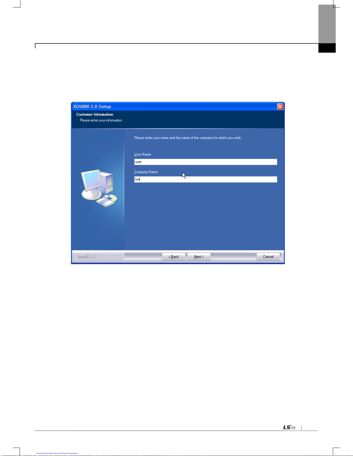
Chapter 6 Communication Parameter
6-7
(3) Click the ‘Next’ button. The contract is shown.
(4) Read carefully and press the ‘yes’ button.
(5) Input the name and company name.

Chapter 6 Communication Parameter
6-8
(6) Designates the folder to install the XG5000. If the user wants to change the folder, press the ‘search’ button and
input or select the new folder. The XG5000 needs the 30MB to install. If installation area is not enough, you can’t
install the XG5000.
(7) Select the folder and press the ‘Next’ button.
(8) Check the installation location and press the ‘Next’ button.

Chapter 6 Communication Parameter
6-9
(9) Among installation, XG5000 USB driver installation screen shows.
(10) After a while, installation is complete.
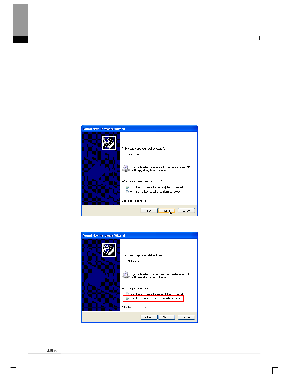
Chapter 6 Communication Parameter
6-10
6.3.2 USB device driver in st allation
In case of installing the XG5000 first time, the user should install the USB device driver additionally. In case of not
connecting with USB, install the USE device driver like below.
In the window 2000, when installing the XG5000, USB device driver is installed automatically. But in the window
XP , the user should install it additionally.
(1) Check if there is the Drivers folder in the XG5000 folder. There are two files, GmUSBD.sys, GmUSBD.inf. If there is
no folder or driver file, reinstall the XG5000.
(2) Turn the PLC power on and connect the USB connector to PC. If it is done, ‘Found new hardware wiz ard’ shows
and notify the installation of the device driver.
(3) Select ‘Install from a list or specific location (Advanced)’.
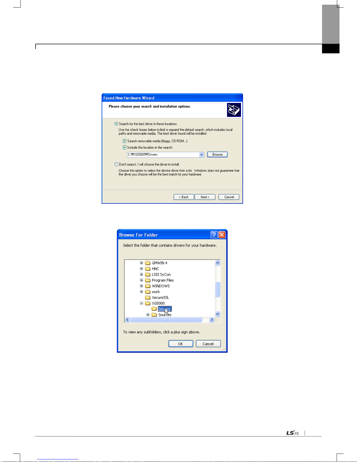
Chapter 6 Communication Parameter
6-11
(4) Among driver searching options, select “Search for the best driver in these locations” and check “Include this location in the
search”.
(5) Click [Browse] button. On Browse Folder Dialog Box, select Drivers’ folder where XG5000 is installed.
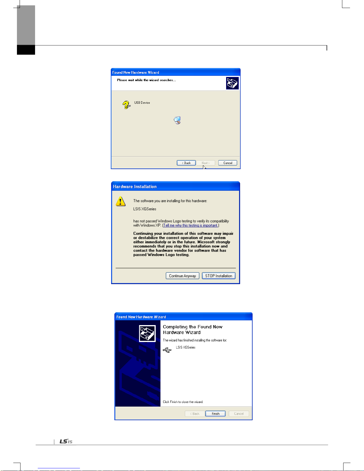
Chapter 6 Communication Parameter
6-12
(6) Click [OK] button. Then, a computer starts searching for the driver files in the selected folder.
(7) If the computer found the most suitable device driver, you will be asked to decide to install the selected device driver.
Since USB device driver operated stably based on Windows OS, you may click [Continue Anyway] button
(8) If the device driver has been installed completely, the Installation Complete Dialog Box will be displayed as follows. Click
[Finish] button to end the installation of the driver.

Chapter 6 Communication Parameter
6-13
6.3.3 Confirmation of installed USB dev ice driver
If USB connection is not available, check the installation status of the device driver as follows
(1) Click the right button of the mouse with the cursor on [My Computer] icon on the background screen, and select [Manage]
on the menu
(2) Computer Management Dialog Box will be displayed as shown in the figure below. On the left tree list of Dialog
Box, click [Computer Management (Local)]-[System Tools]-[Device Manager] in regular orde r . The i tems displ ayed
on the right list may be different according to devices installed on the computer.
(a) Normal Case
The USB device driver for XGT PLC has been installed successfully, if the list [LSIS XG Series] appears with the figure
under [Universal Serial Bus Controller].
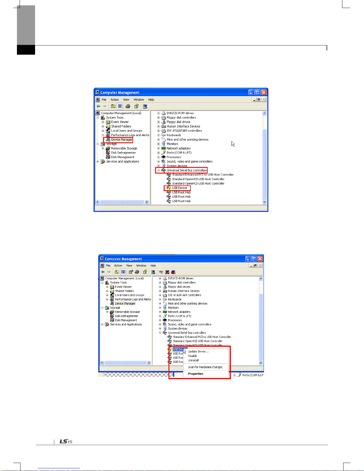
Chapter 6 Communication Parameter
6-14
(b) Abnormal Case
The device driver has not been installed successfully, if the f ollowin g figure is display ed.
If the USB driver for XGT PLC is not installed successfully, reinstall the USB driver for XGT PLC in the following steps.
(1) On the device driver with the icon with an exclamation mark, click the right button of the mouse. Select [Update Driver] on
the menu.
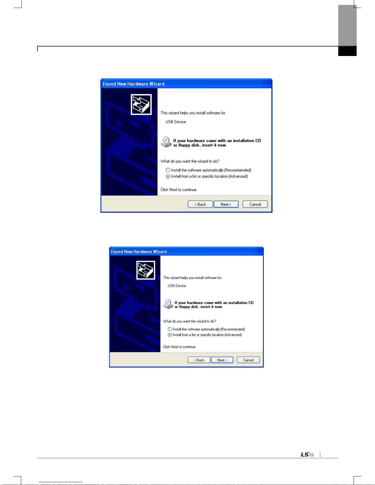
Chapter 6 Communication Parameter
6-15
(2) H/ W Update Wizard Dialog Box will appear. Select the option “Installation from a list or specific location (Advanced)” and
click [Next]. The next sequence is manually the same as in Installation of Device Driver.
If the USB driver for XGT PLC is not installed successfully, reinstall the USB driver for XGT PLC in the following steps
(1) If the device driver has been installed incorrectly or in error, execute H/W Update Wizard. Select the option
“Installation from a list or specific location (Advanced)” and click [Next].

Chapter 6 Communication Parameter
6-16
(2) On search and installation options, select [Don’t Search. I will choose the driver to install.] and click [Next]
(3) Click [Hav e Disk…] on the Dialo g Box below

Chapter 6 Communication Parameter
6-17
(4) If Installation Dialog Box is di splay ed on the dis k, click [B rowse] but ton.
(5) From the Browse File Dialog Box, move to the folder XG5000 is installed in. Select drivers folder to display GmUSBD.inf
file. With this file selected, click [Open] button.
(6) On the item of ‘Copy manufacturer’s files from’, a directory with the file of the device driver will be displayed. Click [OK]
button

Chapter 6 Communication Parameter
6-18
(7) On ‘Show compatible hardware’ list of the device driver Select Dialog Box, select “LSIS XGSeries” driver and then click
[Next] button
(8) Hardware Installation Dialog Box will appear. Click [Continue Anyway] to go on with the installation

Chapter 6 Communication Parameter
6-19
(9) Completing the Hardware Update Dialog Box will appear. Click [Finish] button to end the installation of the driver

Chapter 6 Communication Parameter
6-20
6.4 Communication Module Registration
In order to use Cnet I/F module, communication parameters shall be specified in XG5000. And for system setting of Cnet I/F
module positioned at an optional place, its applicable module shall be registered in XG5000. How to registe r the opti onally
positioned Cnet I/F module depends on On/Off line status as described below.
6.4.1 Off-line registration of Cnet I/F module
This method is used when the user writes the parameter related with communication about communication
module that is not connected with PLC.
(1) Execute the XG5000 and select [Project]-[New Project] or click the icon ( ).
(2) Input the project name, file location and PLC type the user is using.
(3) select [Project]-[Add Item]-[Communication Module]. And then select “PLC type” and click “Add Module”.
If the followi ng screen appears, select the Cnet in the Type and specify the slot number.

Chapter 6 Communication Parameter
6-21
6.4.2 Online registration of Cnet I/F module
Step (1), (2) of off-line registration is same and the next step is as follows.
(1) Input the project name, file location and PLC type the user is using.
(2) If connection fails, check the connection status. Select [Online] – [Connection settings] or click the icon ( ). There
are many connection types (RS-232C, USB, Ethernet and modem) and depths (Local, Remote 1, Remote 2). For
remote connection, refer to the 7.3.
(3) In order to check the currently mounted modules, select [Online]-[Diagnosis]-[I/O Information…]. Then all
currently mounted communication modules in the basic and extension bases are searched and shown in the
Project window.
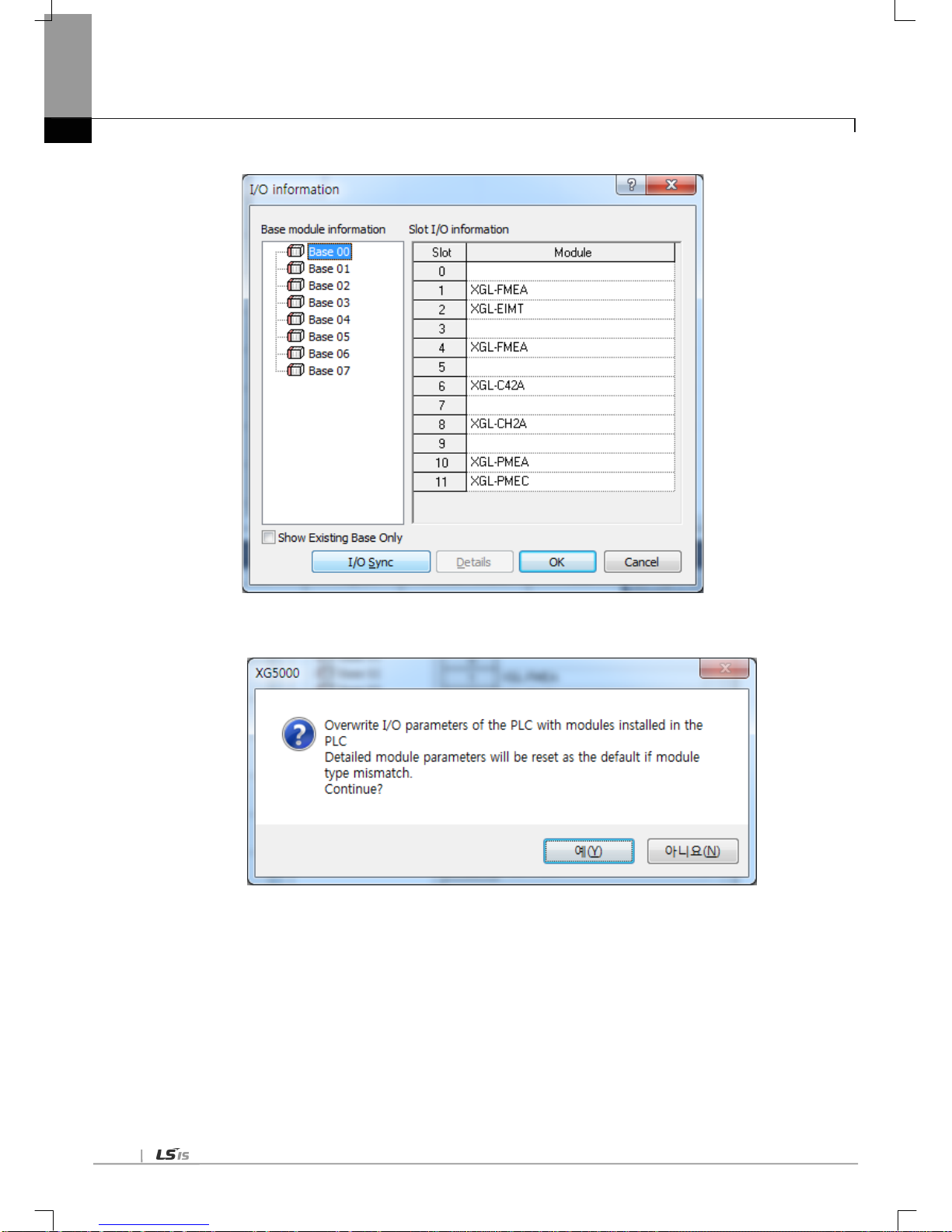
Chapter 6 Communication Parameter
6-22
(4) Click “I/O Sync”.
(6) Read the message. If there is no problem, click “OK”
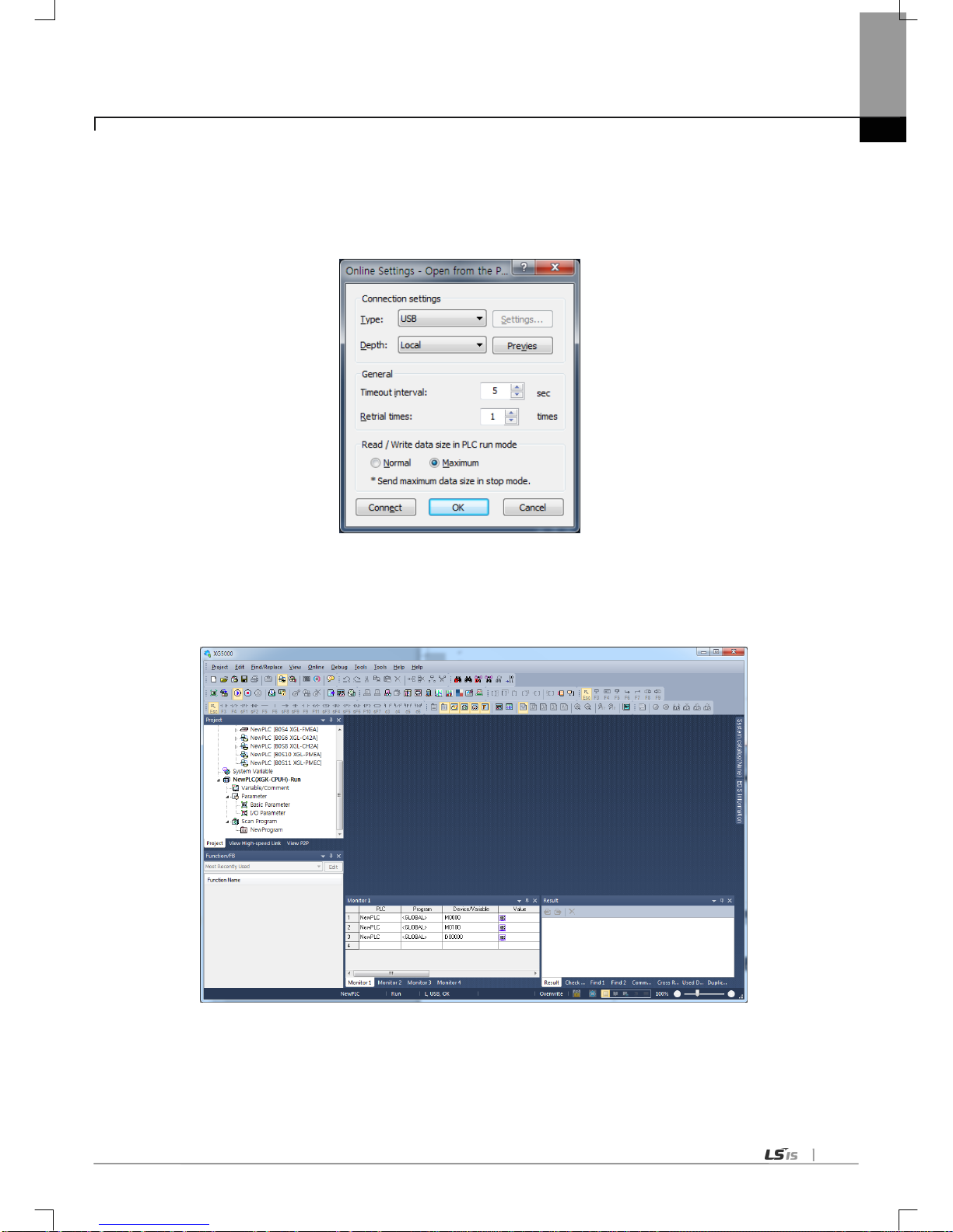
Chapter 6 Communication Parameter
6-23
6.4.3 Ho w to read the p arameter saved in the PLC
T o read the parameter saved in the PLC, follow the below sequence.
(1) Select the ‘Open from PLC’.
(2) A fter setting the connection type and depth, click the “connect”
(3) The user can check the setting value of standard settings and P2P saved in the PLC.

Chapter 6 Communication Parameter
6-24
6.5 How to set the Transmission Standard
6.5.1 Ho w to set
To operate the Cnet I/F module according to communication standard and mode defined by the user, follow the
lower steps. For example, the following example sets the XGL-CH2A (RS232 1 port, RS422 1port) equipped at the
base 0, slot 2 according the lower standard.
(1) Communication standard
(a) Channel 1: RS-232C, 9,600 Bps, 8/1/None, Null modem, XGT server, self station number 0
(b) Channel 2: RS-485, 9,600 Bps, 8/1/None, Null modem, Use P2P, self station number 10
(2) Execution sequence
(a) Read I/O Information
Read the IO information of the currently mounted modules by select [Online]-[Diagnosis]-[I/O Information…] then click
“I/O Sy nc”,
(b) Standard settings
If the user double-clicks the Cnet I/F module mounted at the no. 8, standard settings shows. Write the items like
the lower figure.
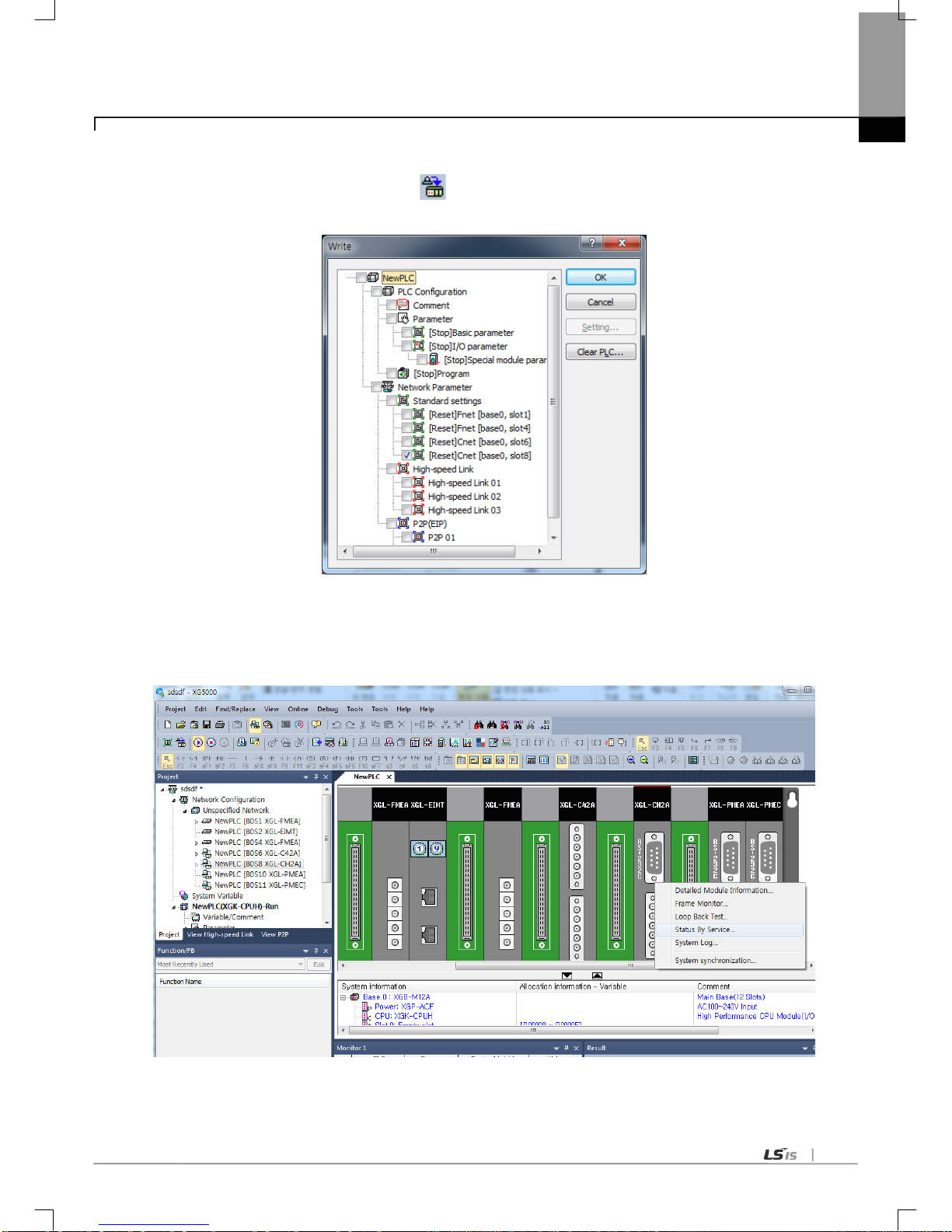
Chapter 6 Communication Parameter
6-25
(c) Writing the parameter
1) Select [Onlin e]-[Write…] or click the icon (
).
2) Check the setting module and click the ‘OK’.
(d) Checking the operation
1) Select [Oline]-[Communication module setting]-[System Diagnosis]
2) Click the right button at the relevalet module and click the ‘Frame Monitor’ or ‘Status By Service’ to check the
communication
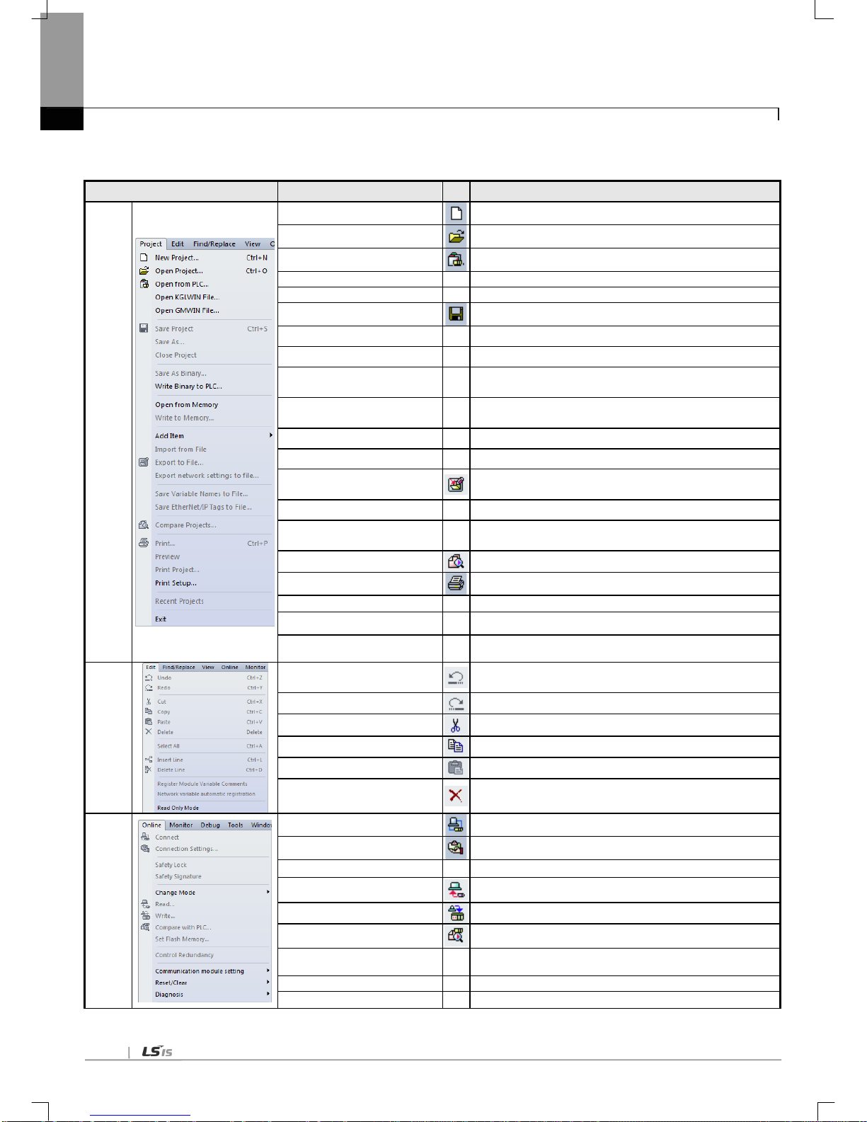
Chapter 6 Communication Parameter
6-26
6.5.2 Menu bar and shortcut of XG5000
The following is menu bar and short cut of XG5000.
Menu bar
Menu
Icon
Description
Project
New Project
Create a new project.
Open Project
Open the existing project.
Open from PLC
Upload the project and program stored in PLC.
Open KGL WIN File
Open the project file for KGLWIN.
Open GMWIN File
Open the project file for GMWIN.
Save Project
Save the project.
Save As -
Save the project as a different name.
Close Project
Close the project.
Save As Binary
Saved as the binary file that cannot show the details of the
project.
Write Binary to PLC
Write the binary file with the PLC. Y ou cannot see the
details of the project.
Add Item Add Item to Project
Import from File Import the item from the file to the project
Export to File
Save the selected items included opened project as
separated file.
Save V ariable Names to File
Save variable names to file for using other programs.
Save EtherNet/IP Tags to file
Register EtherNet/IP tag and save the established
EtherNet/IP tag list to the file.
Compare Project
Compare two projects stored in PC and displays its result.
Print
Print the activ e window’ s det ails.
Preview
-
Previously display the screen to be printed.
Print Project -
Select the project item to print
Print Setup -
Set the printer options.
Edit
Undo
Cancel the edit on Program Edit Window to recover its
previous status.
Redo
Recover the edit cancelled above.
Cut
Copy the selected block to clipboard and delete the block.
Copy
Copy the selected block to the clipboard.
Paste
Copy from the clipboard onto Edit Window.
Delete
Delete the selected block or items.
Online
Connect
Connect with PLC
Connection Setting
Specify the connection method.
Change Mode
Change the mode of connected PLC
Read
Read parameter/program/comment from PLC.
Write
Write parameter/program/comment on PLC.
Compare with PLC
Compare the project with project saved in PLC
Set Flash Memory -
Shows the window for setting up the flash memory.
Control Redundancy
Control the redundancy PLC.
Communication module setting
Set about communication module

Chapter 6 Communication Parameter
6-27
Reset/Clear Reset the PLC or delete the dat a
Tools
T emperat ure Control
Execute the XG-TCON tool.
Position Control
Execute the XG-PM tool.
Address Calculator
Open Address calcilator
Star t Simulator
Start simulator
ASCII T able
Open ASCII T able
Customize
Open customize windows
Options
-
Open XG5000 option window s
EDS
Manage EDS file
PROFICON
Open PROFICON
View
Project Window
Open project window to XG5000
Open P2P window
-
Open P2P window to XG5000
Open High-s peed link window
-
Open HS window to XG5000
… - The Following description, please r efer to the XG5000 us er’s guide.
Window
New Window
Open a new window on the active window.
Split
Divide the active window.
Auto hide all Hide all windows automatically except current windw
New Horizontal T ab Group
Arrays the several windows belonging to XG5000 with the
horizontal tab
New Ver tical Tab Group
Arrays the several windows belonging to XG5000 with the
vertical tab.
Move to Next Tab Group
Move to the next tab group.
Move to Previous Tab Group
Move to the previous tab group.
Close All
Close all windows belonging to XG5000.
Reset Window Layout
-
Reset the default layout of the project.
Help
Help
Open the help for each item
LSIS Home Page
Connect to LSIS Home Page via the Internet.
About XG5000
Shows XG5000 information.

Chapter 6 Communication Parameter
6-28
6.6 How to set the Parameter according to Service
6.6.1 Exclusive Service
Through this exclusive service function built-in Cnet I/F module, information and data of PLC can be read or written in PC
and associated devices without additional programming in PLC. It operates as a server in communication network and
responds to memory Read/Write request conforming to exclusive XGT protocol in external devices or PC, or conforming to
Modbus protocol. In order to use the exclusive service, select the operation mode for the channel used for server among
Cnet channels 1 and 2 when setting basic communication. It supports XGT server and Modbus server which respond to
both RTU and ASCII format. Since Cnet I/F module respective channel operates separately, it can not be set to other type of
server. Refer to exclusive service related items in “Diagnosis and error code” for details on check and diagnosis of normal
operation of the exclusive service.
(1) XGT server
During the exclusive service, all the frames used in XGT server shall not exceed 256 Bytes. And the characters used in all
the frames are of ASCII code. If used as multi-drop, up to 32 stations can be connected with. Be careful not to set the
duplicated station number to the identical network when setting station number. Communication speed/stop bit/parity bit/data
bit of all the Cnet I/F modules shall be surely identical on the network if used as multi-drop. XGT server supports only the
memory Read/Write function of the Exclusive XGT protocol.
(2) Modbus server
It is used when the correspondent device to communicate with operates as Modbus Client. It supports both Modbus’s
ASCII Mode and RTU Mode, whi ch can be specified in the active mode of standard settings window.
[Figure 6.6.1] Modbus server standard settings screen
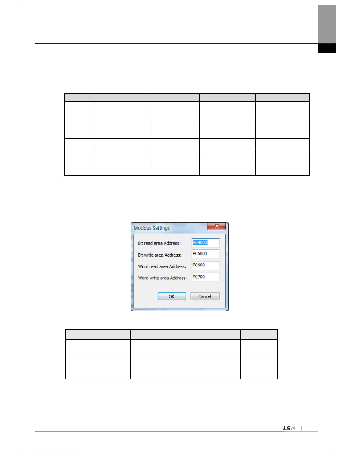
Chapter 6 Communication Parameter
6-29
Correspondent client device shall request within the range described in the table below.
For example, bit Read request is available up to 2000 bits, and bit Write request is available up to 1968 bits
(using Modbus RTU).
Code (Hex)
Purpose
Used area
Address
Max. Response data
01
Read Coil Status
BIT OUTPUT
0XXXX
2000 COILS
02
Read Input Status
BIT INPUT
1XXXX
2000 COILS
03
Read Holding Registers
WORD OUTPUT
4XXXX
125 REGISTERS
04
Read Input Registers
WORD INPUT
3XXXX
125 REGISTERS
05
Force Single Coil
BIT OUTPUT
0XXXX
1 COIL
06
Preset Single R egister
WORD OUTPUT
4XXXX
1 REGISTER
0F
Force Multiple Coils
BIT OUTPUT
0XXXX
1968 COILS
10
Preset Multipl e Registe rs
WORD OUTPUT
4XXXX
120 REGISTERS
[Table 6.6.1] Modbus command code
For the request of each instruction code, applicable area shall be set for XGT PLC memory.
It is available through “Modbus Setting” window as shown in the figure below which is displayed if “Setting” button clicked
after active with Modbus ASCII server/RTU server selected on the “Modbus setting of Cnet operation mode” window.
[Figure 6.6.2] Modbus server memory setting
Details of respective setting item are as follows;
Item
Description
Remarks
DI area address
XGT address applicable to digital input area
Bit address
DO area address
XGT address applicable to digital output area
Bit address
AI area address
XGT address applicable to analog input area
Word address
AO area address
XGT address applicable to analog output area
Word address
[Table 6.6.2] Details of Modbus Area
The address value set in the respective item is the base address of the applicable area.
In the [Figure 6.6.2], start address of bit read area is assigned at the first bit of M0000 word. Start address of word

Chapter 6 Communication Parameter
6-30
write area is assigned at the M300.
Address input data should be in effective area like M, P
Since modbus address is 1~9999 (decimal), size of bit IO is 9999/8=1249.875 (namely 1249, byte should be integer
unit)
The size of word IO is 9999*2=19998 byte.
In case of XGK CPU, bit read/write address is word + Bit.
▷ Example when the first bit of second word of read area is start address (ex: 0x10020)
In case of XGI CPU, bit read/write address is bit.
▷ Example when 10
th
bit of read area is start address (ex: 0x10009)

Chapter 6 Communication Parameter
6-31
6.6.2 P2P service
P2P service executes client operation of the communication module as realized with parameters setting which was set by
instruction blocks in case of GM/MK. Four P2P instructions available in Cnet I/F module are Read/Write/Send/Receive.
Send/Receive are used in case of ‘user definition frame’ and Read/Write are used in case of ‘XGT dedicated client or ‘modbus
RTU/ASCII client’.
P2P service’s registration and edit is executed in XG5000 where up to 8 P2P parameters can be set. Respective P2P
parameter is composed of up to 64 P2P blocks.
The following [Figure 6.6.3] shows an example of P2P parameter setting wind ow in XG5000
[Figure 6.6.3] example of P2P parameter setting

Chapter 6 Communication Parameter
6-32
P2P parameters registration window
Up to 8 P2P parameters can be set
Multiple P2P parameters can be set for an identical Cnet I/F module
However, Enable is available only for 1 parameter among the multiple P2P parameters for the identical Cnet I/F
module
Respective P2P parameter is composed of P2P channel, P2P block and user defined frame
P2P edit window
Up to 64 P2P blocks can be registered and edited.
(1) Configuration of P2P parameters
In order to use P2P service the user needs to execute setting for the operation desired on the P2P parameters window.
P2P parameters are composed of 3 kinds of information as shown in the figure below
[Figure 6.6.4] P2P parameter configuration screen
▶P2P channel
P2P channel setting to define the communication protocol of the P2P service to execute
XGT/Modbus available
Separate setting for respective channels. Applied only if basic setting’s “P2P driver” is None.
▶P2P block
64 P2P blocks setting separately operated
▶User definition frame
Registration of user defined frame

Chapter 6 Communication Parameter
6-33
(2) P2P channel setting
Cnet I/F module provides 2 communication channels (channel 1, channel 2) separately operated.
Driver type of the channels can be defined respectively for P2P service. In order for P2P channel to operate as client, active
mode of standard settings should be ‘Use P2P’. Channel setting according to active is as follows.
Active mode
P2P Channel setting
When selecting ‘Use P2P’ in the active mode, available driver and meaning in the XGT Cnet are as follows.
Driver Meaning
User definition frame
When sending/receiving the user definition frame
XGT client
When reading/writing the memor y of XGT
Modbus ASCII client
When acting as Modbus client and ASCII mode
Modbus RTU client
When acting as Modbus client and RTU mode
[Table 6.6.3] Driver table
If XGT or modbus is selected as P2P driver about communication channel, the user definition frame can’t be used.

Chapter 6 Communication Parameter
6-34
▶ Meaning of modbus function code
Code
(hex)
Purpose Data address Reference
01
Output Contact Status Read (Read Coil Status)
0XXXX(bit-output) Bit read
02
Input Contact Status Read (Read Input Status)
1XXXX(bit-input) Bit read
03
Output Register Read (Read Holding Registers)
4XXXX(word-output) Word read
04
Input Register Read (Read Input Registers)
3XXXX(word-input) Word read
05
Output Contact 1 Bit Write (Force Single Coil)
0XXXX(bit-output) Bit write
06
Output Register 1 Word Write
(Preset Singl e Registe r)
4XXXX(word-output) Word write
0F
Output Contact Continuous Write
(Force Multiple Coils)
0XXXX(bit-output) Bit write
10
Output Register Continuous Write
(Preset Multipl e Regis ter)
4XXXX(word-output) Word write
(3) P2P block setting
If the user se lects t he P2 P block of relevant parameter in th e P2 P parameter set ting windo w, P2P block setting
window shows. B lock setting window of all prot ocol are as follows and ac tivated area is different acc ording to
protocol ty pe in the P2P channel .
P2P driver
P2P block setting

Chapter 6 Communication Parameter
6-35
6.7 Operation Start
XGT Cent I/F module’s operation is divided into P2P service and server function generally. When setting the Cnet I/F
module as server, follow the 6.7.1 and when setting the Cnet I/F module as P2P service, follow the 6.7.2 about
parameter setting
6.7.1 In case o f acting as serv er
(1) Connection setting
(a) Select [Online]-[Connection settings] or click icon ( ).
(b) A fter setting the connection option according to user, click the ‘connection’.
(2) Reading IO information
Select [Online]-[Diagnosis]-[I/O Information] then click “I/O Sync”. Then IO information of currently mounted is
shown on the project window.
(3) Standard s ettings
(a) Double-click the relevant Cnet I/F module and execute the standard settings window. Designate the
communication type, spe ed, mode m type, dat a bit, st op bit and station.
(b) Modem initialization is available in case of dial-up modem.
(c) Delay time setting is available in case of RS-422/485 and time out setting is available in case of RS-422/485
P2P mode.
* When using the Modbus ASCII server, data bit should be 7.

Chapter 6 Communication Parameter
6-36
(4) Selecting the active mode
(a) Selects the active mode.
(b) XGT Cnet I/F module supports XGT server, Modbus ASCII server, Modbus RTU server.
(5) Writing the parameter
(a) Select [Online] - [Write] or click the icon ( ).
(b) Select the module in which parameter setting is completed.
(c) After writing, reset the relevant module.
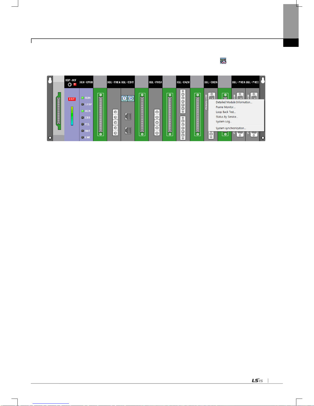
Chapter 6 Communication Parameter
6-37
(6) Checking the operation
(a) Select [Online]-[Communication module setting]- [System Diagnosis] or click the icon (
).
(b) Click the right button on the the relevant module and click Frame Monitor or Status By Service.
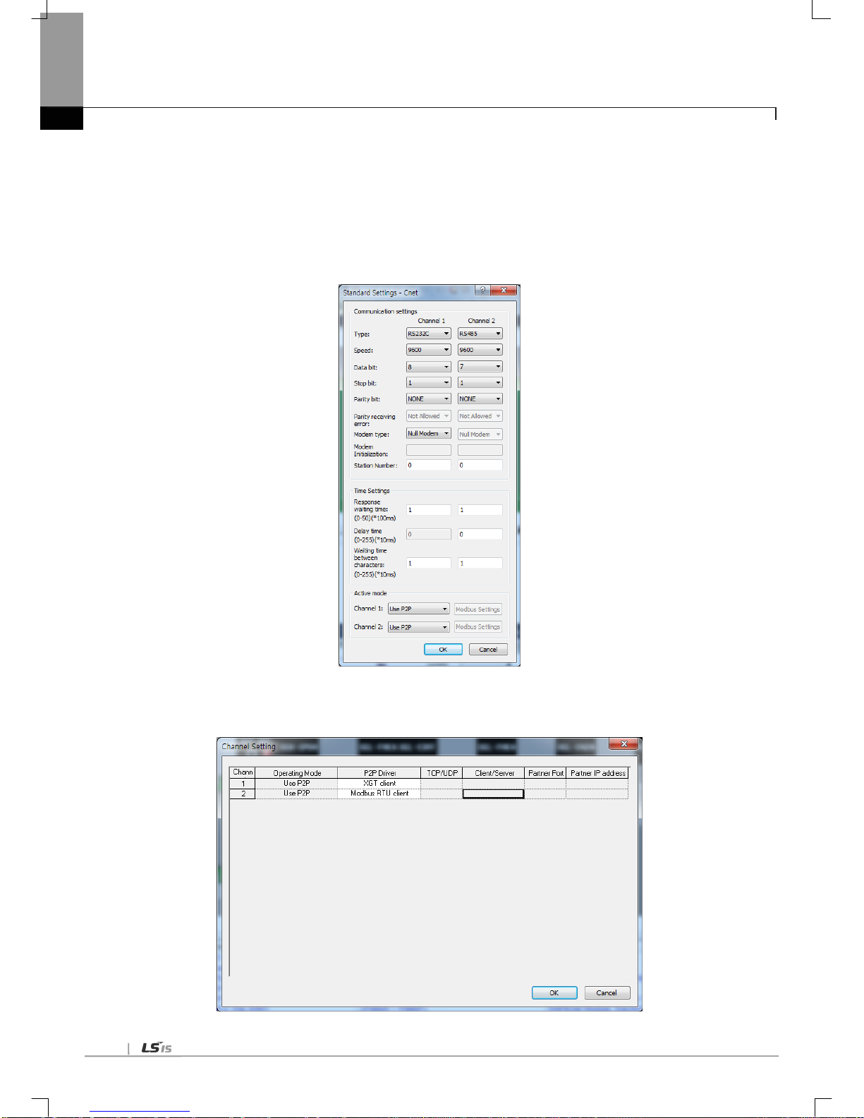
Chapter 6 Communication Parameter
6-38
6.7.2 In case o f acting as P2P service (cli ent)
(1) Standard s ettings
(a) Step 1~3 of chapter 6.7.1 is same.
* In case of acting as ASCII client, data bit is 7.
(b) Select Active mode as Use P2P .
(2) P2P channel setting
(a) Select P2P Driver according to protocol.
(b) P2P Driver supports User Definition Frame, XGT Client, Modbus RTU/ASCII Client.

Chapter 6 Communication Parameter
6-39
(3) P2P block setting
(a) A ccordi ng to ty pe of client , P2P block setting is activated differently.
(b) Fill the activated cell according to protocol.
*In case of user definition frame, it is available when frame is written in the user definition frame.
(4) Writing the parameter
(a) Select [Online] – [ Write] or click the icon ( ).
(b) Select the module in which parameter setting is completed.
(c) After writing, reset the relevant module.

Chapter 6 Communication Parameter
6-40
(5) Enabling the link
(a) Select [Online]-[Communication module setting]-[Enable Lin k] or clic k the icon (
).
(b) Click the P 2P to enable and cli ck Wri te.
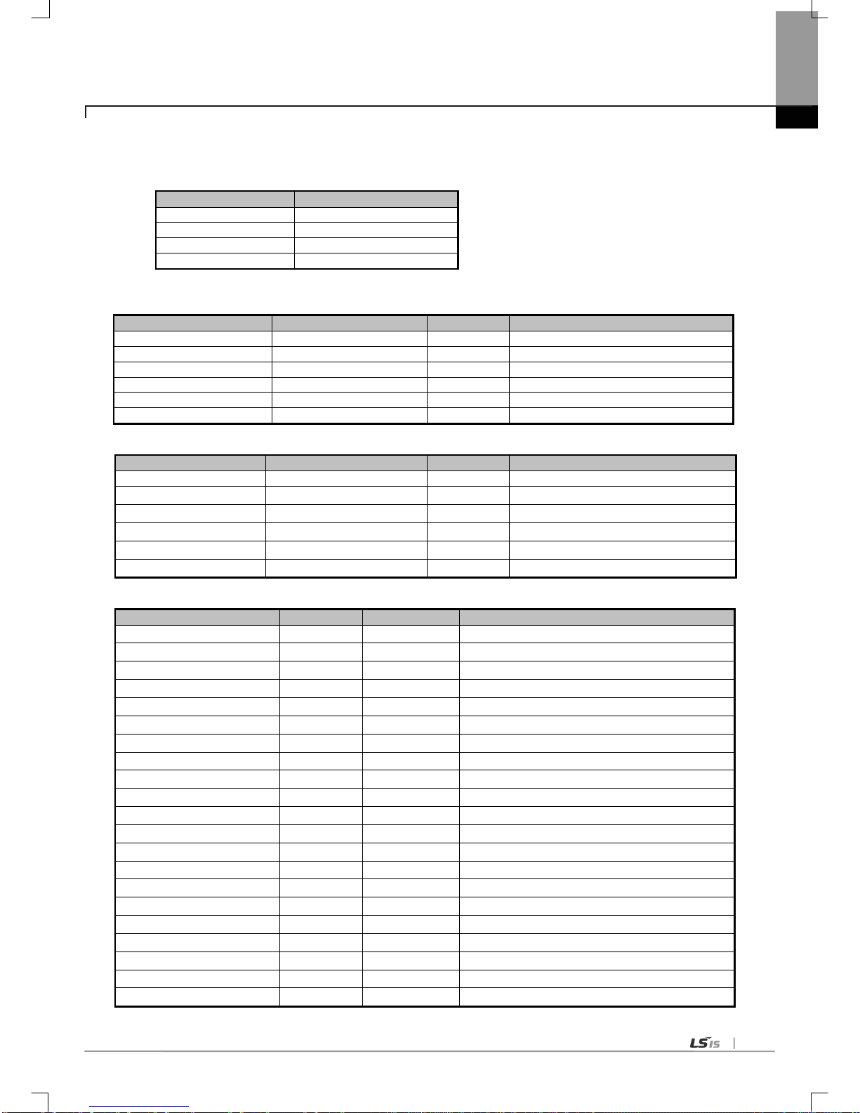
Chapter 6 Communication Parameter
6-41
* Enable Link through flag
It describes “Enable Link” method through flag. The following XG5000 version, CPU OS version is needed.
Item
Version
XG5000
V3.61 or above
XGR CPU
V1.91 or above
XGI CPU
V3.4 or above
XGK CPU
V3.7 or above
Flag list related with “Enable Link”
-XGR
Flag
Data type
Device
Description
_HS_ENABLE_STATE
ARRAY[0..1 1] OF BOOL
%FX19040
HS link enable/disable current state
_HS_REQ
ARRAY[0..1 1] OF BOOL
%FX31520
HS link enable/disable request
_HS_REQ_NUM
ARRAY[0..1 1] OF BOOL
%FX31536
HS link enable/disable setting
_P2P_ENABLE_STATE
ARRAY[0..7] OF BOOL
%FX19072
P2P enable/disable current state
_P2P_REQ
ARRAY[0..7] OF BOOL
%FX31552
P2P enable/disable request
_P2P_REQ_NUM
ARRAY[0..7] OF BOOL
%FX31568
P2P enable/disable setting
-XGI
Flag
Data type
Device
Description
_HS_ENABLE_STATE
ARRAY[0..1 1] OF BOOL
%FX15840
HS link enable/disable current state
_HS_REQ
ARRAY[0..11] OF BOOL
%FX16480
HS link enable/disable request
_HS_REQ_NUM
ARRAY[0..1 1] OF BOOL
%FX16496
HS link enable/disable setting
_P2P_ENABLE_STATE
ARRAY[0..7] OF BOOL
%FX15872
P2P enable/disable current state
_P2P_REQ
ARRAY[0..7] OF BOOL
%FX16512
P2P enable/disable request
_P2P_REQ_NUM
ARRAY[0..7] OF BOOL
%FX16528
P2P enable/disable setting
-XGK
Flag
Data type
Device
Description
_HS1_ENABLE_STATE
BIT
F09600
HS link 1 enable/disable current state
_HS2_ENABLE_STATE
BIT
F09601
HS link 2 enable/disable current state
_HS3_ENABLE_STATE
BIT
F09602
HS link 3 enable/disable current state
_HS4_ENABLE_STATE
BIT
F09603
HS link 4 enable/disable current state
_HS5_ENABLE_STATE
BIT
F09604
HS link 5 enable/disable current state
_HS6_ENABLE_STATE
BIT
F09605
HS link 6 enable/disable current state
_HS7_ENABLE_STATE
BIT
F09606
HS link 7 enable/disable current state
_HS8_ENABLE_STATE
BIT
F09607
HS link 8 enable/disable current state
_HS9_ENABLE_STATE
BIT
F09608
HS link 9 enable/disable current state
_HS10_ENABLE_STATE
BIT
F09609
HS link 10 enable/disable current state
_HS11_ENABLE_STATE
BIT
F0960A
HS link 11 enable/disable current state
_HS12_ENABLE_STATE
BIT
F0960B
HS link 12 enable/disable current state
_HS1_REQ
BIT
F10300
HS link 1 enable/disable request
_HS2_REQ
BIT
F10301
HS link 2 enable/disable request
_HS3_REQ
BIT
F10302
HS link 3 enable/disable request
_HS4_REQ
BIT
F10303
HS link 4 enable/disable request
_HS5_REQ
BIT
F10304
HS link 5 enable/disable request
_HS6_REQ
BIT
F10305
HS link 6 enable/disable request
_HS7_REQ
BIT
F10306
HS link 7 enable/disable request
_HS8_REQ
BIT
F10307
HS link 8 enable/disable request
_HS9_REQ
BIT
F10308
HS link 9 enable/disable request

Chapter 6 Communication Parameter
6-42
Flag
Data type
Device
Description
_HS10_REQ
BIT
F10309
HS link 10 enable/disable request
_HS11_REQ
BIT
F1030A
HS link 1 1 enable/disable request
_HS12_REQ
BIT
F1030B
HS link 12 enable/disable request
_HS1_REQ_NUM
BIT
F10310
HS link 1 enable/disable setting
_HS2_REQ_NUM
BIT
F10311
HS link 2 enable/disable setting
_HS3_REQ_NUM
BIT
F10312
HS link 3 enable/disable setting
_HS4_REQ_NUM
BIT
F10313
HS link 4 enable/disable setting
_HS5_REQ_NUM
BIT
F10314
HS link 5 enable/disable setting
_HS6_REQ_NUM
BIT
F10315
HS link 6 enable/disable setting
_HS7_REQ_NUM
BIT
F10316
HS link 7 enable/disable setting
_HS8_REQ_NUM
BIT
F10317
HS link 8 enable/disable setting
_HS9_REQ_NUM
BIT
F10318
HS link 9 enable/disable setting
_HS10_REQ_NUM
BIT
F10319
HS link 10 enable/disable setting
_HS11_REQ_NUM
BIT
F1031A
HS link 11 enable/disable setting
_HS12_REQ_NUM
BIT
F1031B
HS link 12 enable/disable setting
_P2P1_ENABLE_STATE
BIT
F09620
P2P1 enable/di sable current state
_P2P2_ENABLE_STATE
BIT
F09621
P2P2 enable/di sable current state
_P2P3_ENABLE_STATE
BIT
F09622
P2P3 enable/di sable current state
_P2P4_ENABLE_STATE
BIT
F09623
P2P4 enable/disable current state
_P2P5_ENABLE_STATE
BIT
F09624
P2P5 enable/di sable current state
_P2P6_ENABLE_STATE
BIT
F09625
P2P6 enable/di sable current state
_P2P7_ENABLE_STATE
BIT
F09626
P2P7 enable/di sable current state
_P2P8_ENABLE_STATE
BIT
F09627
P2P8 enable/disable current state
_P2P1_REQ
BIT
F10320
P2P1 enable/di sable request
_P2P2_REQ
BIT
F10321
P2P2 enable/di sable request
_P2P3_REQ
BIT
F10322
P2P3 enable/di sable request
_P2P4_REQ
BIT
F10323
P2P4 enable/di sable request
_P2P5_REQ
BIT
F10324
P2P5 enable/disable request
_P2P6_REQ
BIT
F10325
P2P6 enable/di sable request
_P2P7_REQ
BIT
F10326
P2P7 enable/di sable request
_P2P8_REQ
BIT
F10327
P2P8 enable/di sable request
_P2P1_REQ_NUM
BIT
F10330
P2P1 enable/di sable setting
_P2P2_REQ_NUM
BIT
F10331
P2P2 enable/disable setting
_P2P3_REQ_NUM
BIT
F10332
P2P3 enable/di sable setting
_P2P4_REQ_NUM
BIT
F10333
P2P4 enable/di sable setting
_P2P5_REQ_NUM
BIT
F10334
P2P5 enable/di sable setting
_P2P6_REQ_NUM
BIT
F10335
P2P6 enable/di sable setting
_P2P7_REQ_NUM
BIT
F10336
P2P7 enable/di sable setting
_P2P8_REQ_NUM
BIT
F10337
P2P8 enable/di sable setting
▶ How to enable link
-HS link/P2P enable/disable setting flag ON HS link/P2P enable/d isable request flag ON
▶ How to disable link
-HS link/P2P enable/disable setting flag OF F HS link/P2P e nable/ disable request flag ON
▶ Y ou can monitor the Enable/Di sable state of the each link through “enable/disable current states” flag.
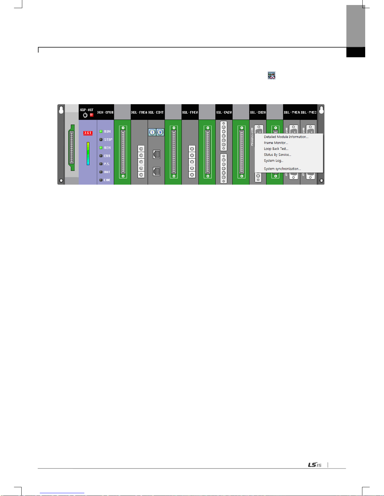
Chapter 6 Communication Parameter
6-43
(7) Checking the operation
(a) Select [Online]-[Communication module setting]-[System Diagnosis] or click the icon (
).
(b) Click the right button on the relevant module and click Frame Monitor or Status By Service.

Chapter 6 Communication Parameter
6-44
6.8 Diagnosis Function of XG5000
6.8.1 Type of diagnosis function
The user can check/diagnose the status of network/system by using the XG5000.
1) CPU module information
2) Detailed module information
3) Frame monitor
4) Loop back test
5) Status by service
(1) System diagnosis
How to check/diagnose the status of network/system by using the XG5000 is described below.
(a) Select [Online]-[Communication module setting]-[System Dianosis] and click the icon (
).
(b) Click the right button on the the relevant module and click Frame Monitor or Status By Service.

Chapter 6 Communication Parameter
6-45
6.8.2 Checking the CPU status
(1) CPU module information
(a) Select [Online]-[Communication module setting]-[System Diagnosis] or click the icon ( ).
(b) Click the right button on the the CPU module and click CPU module information.
6.8.3 Communication module information
(1) Communication module information
(a) Select [Online]-[Communication module setting]-[System Diagnosis] or click the icon (
).
(b) Click the right button on the the relevant module and click Detailed information.

Chapter 6 Communication Parameter
6-46
(2) Meaning of communication module information item
Item
Contents
Standard information
Base Number
Information of base number under diagnosis
Slot Number
Information of slot number under diagnosis
Link Ty pe
Type of communication module under diagnosis
Link information
Station
Station address used in the dedicated service and P2P
Select Option
Information about communication type
(RS-232C, RS-422)
Hardware/Software
information
Hardware version
Hardware version of communication module
Hardware status
Hardware status of communication module
Software version
OS version of communication module
RUN mode/ Additional
information
Run mode
Service information (dedicated service, P2P)
Additio
nal
info.
P2P Enable/Disable
Dedicated
service
Indicates the driver type of dedicated service
PADT Indicates the remote 1/2 connection
System parameter setup information
Indicates if standard parameter is downloaded or not.
Error information of standard communication
parameter
6.8.4 Frame monitor
The user can check the TRX frame of Cnet module by using the frame monitor.
(1) Frame monitor
(a) Select [Online]-[Communication module setting]-[System Diagnosis] or click the icon (
).
(b) Click the right button on the the Cnet module and click Frame Monitor.

Chapter 6 Communication Parameter
6-47
(2) Detail of frame monitor items
Item
Contents
Standard information
Base No.
Information of base number under diagnosis
Slot No.
Information of slot number under diagnosis
Monitor selections
Select Channel
Select channel to monitor
Frame monitor
window
From
Indicates whether it is TX or RX frame.
Result
Indicates the protocol type
1) XGT server
2) XGT client
3) Modbus server
4) Modbus client
5) User definition frame
6) Unknown : frame that Cnet can’t deal with
Size
Size of frame
Time
Ti me when sending/receiving the frame
Frame data Indicates the frame data
View by HEX
Indicates the frame data as HEX
View by ASCII
Indicates the frame data as ASCII
Start
Starts the frame monitor
Stop
Stops the frame monitor

Chapter 6 Communication Parameter
6-48
6.8.5 Loop back test
(1) How to wire the module
(a) Set actiive mode of test module as server.
(b) Disable t he P2P link of test module.
(c) Wire like figure below according to communication port.
1) RS-232C communication: c onnect no. 2 with no. 3
2) RS-422/485 communication: connect TX+ with RX+ and TX- with RX-
<H/W Less than V2.0> <H/W V2.0 or later>
(d) Select [Online]-[Communication module setting]-[System Diagnosis] or click the icon (
).
(2) Loop back test
Select channel to test and click ‘Refresh’.
 Loading...