


Right choice for ultimate yield
LSIS strives to maximize customers' profit in gratitude of choosing us for your partner.
Programmable Logic C ontroller
XGB Ethernet/IP IF Module
User’s Manual
Read this manual carefully before
installing,
wiring, operating, servicing
or inspecting this equipment.
Keep this manual within easy reach
for quick reference.
XBL-EIPT
XGT Series
http://www.lsis.com

Safety Instruction
Before using the product …
For your safety and e ffective oper ation, pl ease read the safety ins tructions t horoughly be fore using t he product.
► Safety Instructions should always be observed in order to prevent accident or risk with the safe and
proper use the product .
► Instructions are divided into “Warning” and “Caution”, an d the mea ning of the ter ms is as f ollows.
This symbol indicates the possibility of serious injury or death if some applicable
instruction is violate d
This symbol indicates the possibility of severe or slight injury, and property
damages i f some appli cable instr uction is v iolated
Moreover, even classified events under its caution category may develop into serious accidents relying on
situations. Ther efore we strongly adv ise users to observe al l precautio ns properly just like war nings.
► The marks displayed on the pr oduct and in the user ’s manual have t he following meanings .
Be careful! Danger m ay be expecte d.
Be careful! Electric shock may occur.
► The user’s manual even after r ead shall b e kept avai lable and access ible to
any user of the product.
Warning
Caution

Safety Instruction
Safety Instructions for design process
Please install a protection circuit on the exterior of PLC so that the whole system may
operate safely regardless of failures from external power or PLC. Any abnormal output or
operation from PLC may cause ser ious proble ms to safety in whole sy stem.
- Install protection units on the exterior of PLC like an interlock circuit that deals with opposite
operations such as emer g ency s top, pr otection circuit, and forward/rever s e rot ati on or install an
interlock circuit that deals wi th high/low limit under its position co ntrols.
- If any system error (watch-dog timer error, module installation error, etc.) is detected during
CPU operation in PLC, all output signals are designed to be turned off and stopped for safety.
However, there are cases when out put signals remai n active due t o device fail ures in Relay and
TR which can’t be det ected. Thus , y ou are recommended to install an addi tion ci rcui t to monitor
the output status for those cri tical outputs which may cause significant problems.
Never overload more than rate d current of output modul e nor allow to have a short circuit.
Over current for a long period time m aycause a fire .
Never let the external power of the output circuit to be on earlier t han PLC power, which may
cause accid ents from abnormal outp ut oroperation.
Please install interlock circuits in the sequence program for safe operations in the system
when exchange data with PLC or modify operation modes using a computer or other
external equipments
Read specific instructions thoroughly when conducting control operations
with PLC.
Warning

Safety Instruction
Safety Instructions for design process
Safety Instructions on inst allation proces s
I/O signal or communication line shall be wired at least 100mm away from a high-voltage
cable or power line. Fail to follow this
Caution
Use PLC only in the environment specified in PLC manual or general standard of data
sheet. I f not, electr ic shock, fir e, abnormal operation o f the product may be caus ed.
Before install or remove the module, be sure PLC power is off. If not, electric shock or damage
on the product may be c aused.
Be sure that every module is securely attached after adding a module or an extension
connector. If the product is installed loosely or incorrectly, abnormal operation, error or dropping
may be caused. In addit
ion, contact failures under poor cable installation will be causing
malfunctions as well.
Be sure that screws get tighten securely under vibrating environments. Fail to do so will put
the product under dir ect vibrat ions which w ill cause electric shock, fire and abnormal operati on.
Do not come in contact with conducting parts in each module, which may cause electric
shock, malfunctions or abnormal op eration.
Caution

Safety Instruction
Safety Instructions for wiring process
Prior to wiring works, make sure that every power is turned off. If not, electric shock or
damage on the product may be caused.
A fter wiring process is d one, make sur e that term inal covers are inst alled properly before
its use. Fail to i nstall the cover may cause electric shocks.
Warning
Check rated voltages and terminal arrangements in each product prior to its wiring
process. Applying incorrect voltages other than rated voltages and misarrangement among
terminals may cause fire or malfunctions.
Secure terminal screws tightly applying with specified torque. If the screws get loose, short
circuit, fire or abnormal operation may be caused.
Securing screws too tightly will cause
damages to the module or malfuncti ons, short ci rcuit, an d dropping .
Be sure t o earth to the ground using Class 3 wires for FG terminals which is exclusively
used for PLC. If the terminals not grounded correctly, abnormal operation or electric shock
may be caused.
Don’t let any foreign materials such as wiring waste ins ide the module while wiring,
which may cause fire, damage on th e product or a bnormal operation.
Make sure that pressed terminals get tighten following the specified torque. External
connector type shall be pressed or soldered using proper equipments.
Caution

Safety Instruction
Safety Instructions for test-operation and maintenance
Don’t touch the terminal when powered. Electric shock or ab normal operati on may oc cur.
Prior to cleaning or tightening the terminal screws, let all the external power off including
PLC power. If not, elect ric shock or a bnormal o peration may occur.
Don’t let the battery recharged, disassembled, heated, short or soldered. Heat, explosion
or ignition may cause inj uries or fire.
Warning
Do not make modifications or disassemble each module. Fire, electric shock or abnormal
operation may occur.
Prior to installing or disassembling the module, let all the external power off including
PLC power. If not, elect ric shock or a bnormal operation may occur.
Keep any wireless equipment such as walkie-talkie or cell phones at least 30cm away
from PLC. If not, abnormal oper ation may be caused.
When making a modification on progr ams or using run to modify functions under PLC
operations, read and comprehend all contents in the manual fully. Mismanagement will
cause damages to produ cts and ac cidents .
Avoid any physical impact to the battery and prevent it from dropping as well. Damages
to battery may c ause l eakag e from it s fluid. When bat tery was drop ped or expos ed under strong
impact, never reuse the batte
ry again. Moreover skilled workers are needed when exchanging
batteries.
Caution

Safety Instruction
Safety Instructions for waste disposal
Product or battery waste shall be processed as industrial waste. The waste may discharge
toxic materials or explode itself.
Caution

Revision History
Revision History
Version Date Contents Revised position
V 1.0 ’10.11 First edition -
V 2.0 ’17. 4 Add servic e setting by tag
XG5000 V4.0 UI updated
CH6
Entire
※ The number of User’s manual is indicated right part of the back cover.
ⓒ 2010 LSIS Co., Ltd All Rights Reserved.

About User’s Manual
About User’s Manual
Congratulations on purchasing PLC of LSIS Co., Ltd.
Before use, make sure to carefully read and understand the User’s Manual about the functions,
performances, installation and programming of the product you purchased in order for correct use and
importantly, let the end user and maintenance administrator to be provided with the User’s Manual.
The User’s Manual describes the produc t. If necessary, you may refer to the following description and order
accordingly. In addition, you may connect our website (http://www.lsis.com/
) and download the information
as a PDF file.
Relevant User’s Manuals
Title Description
No. of User’s
Manual
XG5000 User’s
Manual
It describes how to use XG5000 sof tware especially about online
functions such as programming, printing, monitoring and
debugging by using XGT series products.
10310000512
XGK/XGB Series
Instruction &
Programming
It describes how to use the instructions for programming using
XGK/XGB series. 10310000510
XGB Hardware
User’s Manual
It describes how to use the specification of power/input
/output/expansion modules, system configuration and built-in
High-speed counter for XGB basic unit.
10310000926
XGB Analog
User’s Manual
It describes how to use the specification of analog input/analog
output/temperature input module, system configuration and built-
in PID control for XGB basic unit.
10310000920
XGB Position
User’s Manual
It describes how to use built-in positioning function for XGB unit.
10310000927
XGB Cnet I/F
User’s Manual
It describes how to use built-in comm unication function for XGB
basic unit and external Cnet I/F module.
10310000816
XGB Fast Ethernet
I/F User’s Manual
It describes how to use XGB FEnet I/F module.
10310000873

About User’s Manual
Current XBL-EIPT manual is written based on the following version.
Related OS version list
Product name OS version
XGB-XBCH
V2.80
XGB-XBCS
V1.90
XGB-XBCU
V1.70
XGB-XBMH V1.10
XGB-XBMS V3.80
XGB-XECH
V2.20
XGB-XECS
V1.80
XGB-XECU V1.70
XG5000 V4.21

Contents
◎ Contents ◎
Chapter 1 Overview
1.1 Overview ------------------------------------------------------------------------------------------------------------------------------------------- 1-1
1.2 Features -------------------------------------------------------------------------------------------------------------------------------------------- 1-2
1.3 Product Components ----------------------------------------------------------------------------------------------------------------------------- 1-3
1.3.1 Indication of T ype Na mes ------------------------------------------------------------------------------------------------------------ 1-3
1.4 Software for Using Products ------------------------------------------------------------------------------------------------------------------- 1-4
1.4.1 Confirms for Software ----------------------------------------------------------------------------------------------------------------- 1-4
1.4.2 XG5000 ----------------------------------------------------------------------------------------------------------------------------------- 1-4
1.4.3 Confirmation of Versions ------------------------------------------------------------------------------------------------------------- 1-5
1.5 Compatibility by OS version of XGB EtherNet/IP I/F module --------------------------------------------------------------------------- 1-6
1.5.1 Version information available with communication service by Tag ------------------------------------------------------ 1-6
1.5.2 Operation compatibility according to O/S version ----------------------------------------------------------------------------- 1-6
Chapter 2 Specification
2.1 General S pecification ---------------------------------------------------------------------------------------------------------------------------- 2-1
2.2 Performance Specification --------------------------------------------------------------------------------------------------------------------- 2-2
2.3 Name of Each Part ------------------------------------------------------------------------------------------------------------------------------ 2-3
2.4 Cable S tandards ---------------------------------------------------------------------------------------------------------------------------------- 2-5
2.4.1 UTP Cable ------------------------------------------------------------------------------------------------------------------------------- 2-5
Chapter 3 Instal lation and Trial- Run
3.1 Installation Environment ------------------------------------------------------------------------------------------------------------------------ 3-1
3.2 Cautions when Handling ----------------------------------------------------------------------------------------------------------------------- 3-2
3.3 The Order for Setting up Products till Running -------------------------------------------------------------------------------------------- 3-3
3.4 Available device area ----------------------------------------------------------------------------------------------------------------------------- 3-4
3.5 Installation of Products -------------------------------------------------------------------------------------------------------------------------- 3-6
3.5.1 Installation of XBL-EIPT -------------------------------------------------------------------------------------------------------------- 3-6
3.6 Trial- Run ------------------------------------------------------------------------------------------------------------------------------------------- 3-8
3.6.1 Directions when Configuring Systems -------------------------------------------------------------------------------------------- 3-8
Chapter 4 System Configuration
4.1 Configuration of a Usable System ----------------------------------------------------------------------------------------------------------- 4-1
4.1.1 System Configuration using a Switch --------------------------------------------------------------------------------------------- 4-1
4.1.2 System Configuration not using a Switch ---------------------------------------------------------------------------------------- 4-1
4.2 Configuration of an unusable System ------------------------------------------------------------------------------------------------------- 4-2
4.2.1 System Configuration using a Switch ---------------------------------------------------------------------------------------------- 4-2
4.2.2 Configuration of a Ring System (Configuration of a XGL-EIPT Ring) ---------------------------------------------------- 4-2
Chapter 5 Instal lation of Sof t ware and Communicat ion Parameters
5.1 Installation and Execution of Software ------------------------------------------------------------------------------------------------------ 5-1
5.1.1 Installation of XG5000 ---------------------------------------------------------------------------------------------------------------- 5-1
5.1.2 Installation of USB Device Drive ---------------------------------------------------------------------------------------------------- 5-4

Contents
5.1.3 Confirmation on the Installation of USB Device Driver ------------------------------------------------------------------------ 5-7
5.2 How to Register Communication Modules ----------------------------------------------------------------------------------------------- 5-15
5.2.1 In case of Offline ----------------------------------------------------------------------------------------------------------------------- 5-15
5.2.2 In case of Online ---------------------------------------------------------------------------------------------------------------------- 5-17
5.2.3 In case of Reading Parameter stored in PLC ---------------------------------------------------------------------------------- 5-19
5.2.4 How to Set-up Modules ------------------------------------------------------------------------------------------------------------- 5-20
5.2.5 Menu bar and shortcut of XG5000 ------------------------------------------------------------------------------------------------- 5-21
Chapter 6 EIP Serv ice
6.1 EtherNet/IP Communication Method -------------------------------------------------------------------------------------------------------- 6-1
6.1.1 EtherNet/IP T erms --------------------------------------------------------------------------------------------------------------------- 6-1
6.1.2 EDS File ---------------------------------------------------------------------------------------------------------------------------------- 6-1
6.1.3 Periodic Communication (Implicit) System -------------------------------------------------------------------------------------- 6-2
6.1.4 Aperiodic Communication (Explicit) System ------------------------------------------------------------------------------------- 6-4
6.2 EIP Service ---------------------------------------------------------------------------------------------------------------------------------------- 6-7
6.3 T ag setup -------------------------------------------------------------------------------------------------------------------------------------------- 6-8
6.3.1 XBC/XBM --------------------------------------------------------------------------------------------------------------------------------- 6-8
6.3.2 XEC --------------------------------------------------------------------------------------------------------------------------------------- 6-9
6.3.3 Supported Device by Main Unit --------------------------------------------------------------------------------------------------- 6-10
6.4 Setup of Periodic/Non-periodic Communication Service ------------------------------------------------------------------------------ 6-11
6.4.1 Periodic Client Communication Service ----------------------------------------------------------------------------------------- 6-11
6.4.2 Set-up of Aperiodic Client Communication Service --------------------------------------------------------------------------- 6-18
6.4.3 Periodic Server Communication Service ---------------------------------------------------------------------------------------- 6-20
6.4.4 Aperiodic Server Communication Service -------------------------------------------------------------------------------------- 6-22
6.4.5 Tag naming rule for aperiodic communication services ----------------------------------------------------------------------- 6-22
6.5 Examples ----------------------------------------------------------------------------------------------------------------------------------------- 6-25
6.5.1 Communication with Rockwell 1756-ENBT Communication Module --------------------------------------------------- 6-25
Chapter 7 Diagnosis Function
7.1 System Diagnosis -------------------------------------------------------------------------------------------------------------------------------- 7-1
7.2 System Diagnosis Items and Contents ----------------------------------------------------------------------------------------------------- 7-2
7.3 Troubleshooting ---------------------------------------------------------------------------------------------------------------------------------- 7-8
7.3.1 Check-out through LED in Communication Module --------------------------------------------------------------------------- 7-8
7.3.2 Check out of Module Errors through XG5000 ---------------------------------------------------------------------------------- 7-9
7.3.3 Check-out on Module Errors through System Log --------------------------------------------------------------------------- 7-10
7.4 Remote Communication control -------------------------------------------------------------------------------------------------------------- 7-12
7.4.1 Introduction ------------------------------------------------------------------------------------------------------------------------------- 7-12
7.4.2 Setting and Connection --------------------------------------------------------------------------------------------------------------- 7-13
Appendix
A.1 Terms ------------------------------------------------------------------------------------------------------------------------------------------- A-1
A.2 Flag List ---------------------------------------------------------------------------------------------------------------------------------------- A-5
A.2.1 Special Relay (F) List ------------------------------------------------------------------------------------------------------------- A-5
A.2.2
Network Register (N) List -------------------------------------------------------------------------------------------------------- A-11
A. 3 External Dimension ---------------------------------------------------------------------------------------------------------------------- A-12
A.4 Action when changing OS version from V1.x to V2.0 ------------------------------------------------------------------------------ A-13

Chapter 1 Overview
1
-1
Chapter 1 Ov erv iew
1.1 Overview
This user guide is made out to describe Ether Net/I P I/F module ( Referr ed to as “EIP Module”) amon g XGB PLC s ystem
networks. EtherNet/IP is the protocols where Common Industrial Protocol (CIP: industrial protocols used in common, such
as Device Net , C ontrolNet, CompoNet , etc ) has been l aid on an upper layer of open prot oco l Ethern et. Thus, EtherNet/I P
allows Device Net, Cont rolNet, a nd CompoN et devel opers to s ecure th e i
nteroperability between multi-band and lower network
devices by
applying the same obj ects and prof iles. EIP m odu l e provides two Ether net Ports ( Ether net Port) a nd th e s witch
function requir ed for the existing STAR system is built in and it is the module for transmitt ing data between PCCs or
between PLC and EtherNet/IP I/F IO module.
T o use the communication service by T ag, the following version is necessary .
1) XBL-EIPT: V2.0 or above
2) XBC Series: SU(V1.90 or above), H(V2.80 or above), U(V1.70 or above)
3) XEC Series: SU(V1.80 or above), H(V2.20 or above), U(V1.70 or above)
4) XBM Series: S(V3.80 or above), H(V1.10 or above)
5) XG5000 Software: V4.21 or above

Chapter 1 Overview
1-2
1.2 Features
XGB EtherNet/IP I/F Module have the following features.
(1) Communication Methods: Extensive Client Messaging Support
▶ Encapsulated Messages, UCMM Explicit Messaging
▶ Class 3 Connected Explicit Messaging(Server Only)
▶ Class 1 Connected Implicit(IO) Messaging(Cyclic I/O Service Only)
(2) Compa tibili ty: XGT Ether Net/IP I/F meet EtherNet/IP Conformance Test Suite V ersion 2.10
(3) 100BASE-TX media is provided and 100Mbps/ (Full Duplex) are supported.
(4) It is possible t o be e qu ip ped wit h 24 u nits p er CPU and installation to bas ic b ase and extension base is availab le.
However, only installation to base is possible in XGR system. .
(5) With the bu ilt - in switch , t here is no need to install a separat e switch and hub a nd wirin g is saved and f le xibility in
installation is provided.
(6) As Auto Cross Over- function is p rovided, cabling jo b is conven ient.
(7) A variety of diagnose functions, the states information of modules and networks are provided.
▶ The state of a communication module
▶ The state of a communication service(EIP, Non-circular server)
▶ Auto Scan-function providing an information of own corporation’s and other corporations’ modules
connected into network
▶ The kinds of packets and the quantity of data received by communication module (Network load – prediction
is available)
▶The diagnosis function through network is available

Chapter 1 Overview
1
-3
1.3 Product Components
1.3.1 Indication of T y pe Names
Components of XGB EtherNet/IP I/F module product are described.
Type Name
Components
Remarks
XBL-EIPT
Electric 2 –port EtherNet/IP Module
More than category 5

Chapter 1 Overview
1-4
1.4 Software for Using Products
The following ex plains main programming tools and other production software for usi ng EIP module. For more exact
application of programs and communication, refer to the contents below and apply it to systems.
1.4.1 Confirms for Software
Segment
Component Products
Communication Set-up T ool
XBL-EIPT Communication Module for XGB XG5000
Notice
1) To use the above program, downl oad f rom the curr ent webs ite you are visiting. In case you can not use the
internet, visit near agencies and ask for CD-ROM for installation.
Internet Web - address: http://www.lsis.com
2) To program XG5000, us e RS-232C port and USB of CPU module. For cable, refer to the XGB catalogue.
(USB-301A, PMC-310S)
1.4.2 XG5000
XG5000 is the software for ded icatedly using all comm unication m odules including Ethernet/IP I/F module for basic
parameter set-up, frame make-up, module and network diagnosis.
The following illustration shows the initial screen of XG5000.
[Figure 1.4.1] XG5000 – Initial Screen

Chapter 1 Overview
1
-5
1.4.3 Confirmation of Versions
Check out the version of the module before using XGB EtherNet/IP I/F.
1) Confirmation through XG5000
T o read the information of a communication module, access to the communication module.
.
If interface is normally maintained with CPU, the information like the following illustration can be got.
(1) Execute XG5000
(2) Connect with CPU via access through [Online]-[Connect] on menu.
(3) When connected with CPU, execute the diagnosis of XG5000.
(4) Locate the mouse to the communication module in system diagnosis screen of online menu.
(5) Double-click the communication module or click right button of mouse and select Detailed Module Information.
`
[Figure 1.4.2] Confirmation of Versions through XG5000
2) Confirmation of Versions through Case Label of Products
In each module, the information of the module product is attached to the exterior case.
In case there is no connect or with PC a nd it is impossibl e to check out online, c onfirmatio n is avai lable after you
remove the mod ule in case. The label attached to the back side of a pr oduct and t he type nam e and the vers ion
information is marked.

Chapter 1 Overview
1-6
1.5 Compatibility by OS version of XGB EtherNet/IP I/F module
XGB EtherNet/I P I/F module change d from OS V2.0 to Tag communication. To use the communication ser vice by Tag,
refer to the following description.
1.5.1 Version information available with commun ication service by Tag
1) XBL-EIPT : V2.0, EDS: V er2.10
2) XG5000: V4.21 XG5000 Software: V4.21 or above
3) XBC Series: SU(V1.90 or above), H(V2.80 or above), U(V1.70 or above)
4) XEC Series: SU(V1.80 or above), H(V2.20 or above), U(V1.70 or above)
5) XBM Series: S(V3.80 or above), H(V1.10 or above)
1.5.2 Operation compatibility according to O/S version
Communication Service
O/S version
Action
Client
Server
Implicit message
V2.0 V1.x O
V1.x V2.0 O
Explicit message (Tag Read/Write)
*2)
V2.0 V1.x X
*1)
V1.x V2.0 O
Explicit message (Read/Write)
*2)
V2.0 V1.x O
V1.x V2.0 O
*1) V1.x suppo rts on ly Multi ple Server an d V2.0 sup ports on ly Single Client
*2) Explicit message (T ag Read/Write): Select this to read/write the Tag registered to the external device.
Explicit message (Read/Write): Select this to read / write the CIP Object of the external device.
It should know service code, class, Instance, and Attribute of CIP Object.
Notice
If you are upgrading the OS of XGB EtherNet/IP I/F module from V1.x to V2.0 or replacing V1.x product with V2.0
product, please refer to [A.4 Action when changing OS version from V1.x to V2.0].
<V1.x>
<V2.0>

Chapter 2 Specification
2
-1
Chapter 2 Specification
2.1 General Specification
The general specification of XGT series is as follows.
No. Items Specifications Related st andards
1
Ambient
temperature
0 ~ 55 °C
2
Storage
temperature
−25 ~ +70 °C
3
Ambient
humidity
5 ~ 95%RH (Non-condensing)
4 Storage humidity 5 ~ 95%RH (Non-condensing)
5
Vibration
resistance
Occasional vibration -
Frequency Acceleration Amplitude How many times
IEC61131-2
5≤f< 8.4㎐ - 3.5mm
10 times each
directions
(X , Y and Z)
8.4≤f≤150㎐
9.8㎨
-
Continuous vibration
Frequency Acceleration Amplitude
5≤f< 8.4㎐
-
1.75mm
8.4≤f≤150㎐ 4.9㎨(0.5G) -
6
Shock
resistance
• Peak acceleration: 147 m/s2(15G)
• Duration: 1 1ms
•
Half-sine, 3 times each direction per each axis
IEC61131-2
7 Noise resistance
Square wave
Impulse noise
AC: ±1,500 V
DC: ±900 V
LSIS standa rd
Electrostatic discharge 4kV (Contact discharge)
IEC61131-2
IEC61000-1-2
Radiated electromagnetic field noise 80 ~ 1,000 MHz, 10V/m
IEC61131-2,
IEC61000-1-3
Fast transient/bust
noise
Segment
Power supply
module
Digital/analog input/output
communication interface
IEC61131-2
IEC61000-1-4
Voltage 2kV 1kV
8 Environment Free from corrosive gasses and excessive dust
9 Altitude Up to 2,0 00 m
10
Pollution
degree
Less than equal to 2
11 Cooling Air-cooling
Notice
1) IEC (International Electrote chnical Commission):
An international nongovernmental organization which promotes internationally cooperated standardization in
electric/electronic field, publishes i nternational stand ards and manages applicable estimation system re lated with.
2) Pollution degree:
An index indicating pollution degree of the operating environment which decides insulation performance of the devices. For instance, Pollution
degree 2 indi cates the state generally that only non-conductive pollution
occurs. However, this state contains temporary conduction due to dew
produced.

Chapter 2 Specification
2-2
2.2 Performance Specification
The following table describes the specification of system configuration in accordance with EtherNet/IP I/F module’s media.
When you configure systems, refer to the below table.
Item Standard
Transmission
Standard
Transmission Speed 100Mbps
Transmission Method Base Band
Maximum Extension Distance
between Nodes
100m
Communication Zone Excess
Method
CSMA/CD
Frame Error – Checking
Method
CRC 32 = X
32
+ X26 + X23+ ,,,,, + X2 + X + 1
Topology Line , Star
Diagnosis Function
Module Information , Service S tate , Media Information ,
Auto Scan, Ping T est
Service
Periodic Cline t Implicit IO Client
Aperiodic Client UCMM Client
Periodic Server Implicit IO Server
The Number of
Connections
(Client/Server)
TCP 16/32
CIP(IO Communication) 32/64
The Number of Maximum Services (P2P count) 2
The Number of Maximum Installments 2
Max. setting data
size per block
Periodic client 500 byte
Aperiodic client 512 byte
Media UTP/STP Category 5
Basic Standards
Dimension (mm) 90(H) X 27(W) X 60(D)
Consumption Current (mA)
290
Weight (g)
102

Chapter 2 Specification
2
-3
2.3 Name of Each Part
The name in each module is as follows.
[Figure 2.3.1] The Front View for Module PLC
▶ LED Names and Contents
Silk Mark
LED State
Contents
RUN
ON
Power -on and Process normally operating
OFF
Power –off and Process abnormally operating
I/F
OFF
I/F operating normally with CPU
Flicker/OFF
I/F operating abnormally with CPU
P2P
ON
In case of stetting up P2P Service
OFF
In case of canceling P2P Service
PADT
ON
XG5000 being connected via rem ote control
OFF
XG5000 remote c onnection has been released
SVR
ON
When exterior client has been con nected, Light ON
OFF
When there is no exter ior client connection, Light OFF
MS
Green Light ON
When normal operating
Green Light flickers
When configuration for device is not over
Red Light flickers
In case of wrong set-up or restorable errors happened
Red Light ON
When errors which are impossible to restore have been made
Red Green Light flickers
When self-diag nosis is proceeding
NS
Green Light flickers
When there is no connection of a device
Green Light ON
When there is connection more than 1 with a devic e at least
Red Light flickers
When Timeout with a device more than 1 unit happened
Red Light ON
When repeated IP addr ess has been detected
Red / Green Light
flickers
When self-diag nosis is preceding
n ACT Flicker In case of frame – transmitted and received (n=1,2)
n LNK
ON
When network link has been form ed (n=1,2)
OFF
When network link has not been fo rmed (n=1,2)
LED Display
IP Set-up Switch
LOG Switch
Connector 1
Connector 2

Chapter 2 Specification
2-4
▶ Log Switch
In case of reading Log in communication module and needing to store the Log, if you push it for more than 1 second, it is
stored into Flash area from Memory area. The Log in the memory area is the one erased when power is supplied again
and the Log in Flash area is the one which is maintained when power is supplied again.
▶ IP Set-up Switch (1~90, 94~99)
When IP address has not been inserted via XG5000 within 10 seconds after power was supplied, IP is set up as
‘192.168.250.switch value’.
▶ IP Set-up Switch (91, 92, 93 )
This switch is designed for setting up the inside of communication. If you change it arbitrary, it may cause problems.
▶ IP Set-up Switch (99)
This switch f unctions to configur e the system into a ring form and wh en set-up is not finished, norm al operation is
impossible. It is possible to form a ring system in terms of appearance by supporting 2 connectors but actual ring system
is not supported.

Chapter 2 Specification
2
-5
2.4 Cable Standards
2.4.1 UTP Cable
UTP cable is classified into the 3 types according to the following standards.
▶ With or without Shield: 3 Types (UTP, FTP, STP)
▶ Used - frequency Band: 7 Categories (Category 1 ~ Category 7)
▶ Inflammable Grade: 4 Grades (CMX, CM, CMR, CMP)
1) Kinds of Cables with or without Shield
Classification
Details
Use
UTP(or U.UTP) Unshielded Cables for Hi gh S peed – Signals
Maximum 200MHz
Voice +Information (Data)+ Low grade Video Signal
FTP(or S.UTP)
1 Layer Shield, Cable Core only shielded
* Shield Materi als: AL /Plastic Complex Foil
Or Copper Braid
Maximum 100MHz
Electro Magnetic Interference (EMI)
and Electric Stability
is considered
Voice + Information (Data) + Low grade Video Signal
STP(or S.STP)
Dual - shielded Cons truction,
Pair Shielded Cabl es or
Core Shielded Cables
* Pair - shielded Materials : AL/Plastic Complex Foil
* Core - shielded Materi als : AL/Plastic Complex Foil
or
Copper Braid
Maximum 500MHz
Voice + Information (Data)+ Video Signal
An Alternative to 75Ω – Coaxial Cable
Notice
1) UTP : Unshielded Twisted Paired Copper Cable
FTP : (Overall) Foiled Twisted Paired Copper Cable
STP : (Overall ) Shiel ded(and Shi elded I ndividua lly Pair)Twisted Paired Copper Cable
2) Patch Cable(or Patch Cord)
Instead of S olid Con duct ors, Stranded C on duct ors m a y be used f or the pur pos e of im prov ing the Flex ibil ity of a UT P
4Pair Cable. The materials and sizes of strands used are regulated in accordance with UL444, and representative sizes
and materials are Un-coated AWG 24 (7/0203A).
In other words, diam eter of unshielded wire is 0.203mm and wires ar e stranded in 1+6 str ucture. The materials are
annealed coopers.
UTP
STP
FTP

Chapter 2 Specification
2-6
2) Classification by Frequencies used
Classification Frequency used (MHz)
Transmission
Speed(Mbps)
Uses
Category 1
Voice Frequency
1
T elephone Network (2 Pair)
Category 2
4
4
Multi- Pair Communication Cable
Category 3 16 16
T elephone Network + Computation
Network
Category 4 20 20
1) Computation Network – Transmission
Speed Up
2)Low-loss Communication Cable
Category 5 and
Enhanced
Category 5
100 100
1)Digital Telephone Network +
Computation Network
2)Low Loss, Wideband Cable
Notice
1) The classification c urrently applied at home and abroad is Category 3, 5, Enhanced Ca te gor y 5, and Ca te gor y
6. Category 4 is not now used as Category 5 appears. Category 7 is in STP structure and it is at a
development st age ove r the wo rld.
3) Classification by Non-flammable Grades(Base on UL Certification )
Segment
Induced
Calorie
Induced Time
Combustion
Length
Smoke
Regulation
Remarks
CMP 88(kW) 20 minutes
Less than
73m/min
Regulated
• For Installing ceilings without duct
• Plenum Cable
• UL 910 (Plenum Test)
CMR 150(kW) 30 minutes
Less than
3.6m
Not
Regulated
• V ertical Installation Type
• Non-Plenum Cable
• UL 1666(Riser Test)
CM 21(kW) 20 minutes
Less than
2.4m
Not
regulated
• Gene ral Ty pe
• Non-Plenum Cable
• UL 1581(VTFT T est)
CMX 1(kW) 1 minute
Less than
0.5m
Not
regulated
• Restrictive Use
• Non-Plenum Cable
• UL 1581 (VW-1 T est)
Notice
1) CMG is located in the middle grade between CM and CMR, but generally it is not applied to LAN Cable
such as UTP Cable.
Example) CMG: CAS FT4 (VTFT T est), similar to CM of UL 1581.
→Burner Angle (Horizontality → 45 degree – Upward) a nd S ample Conditions (1/2 interval arra ngem ent
→ A Bundle of 6 ones x 6 units) are different.

Chapter 2 Specification
2
-7
4) An Example (CTP-LAN5) of Category - 5 Twisted Pair Cable(UTP)
Items
Units
Values
Conductor Resistance
(Maximum)
Ω/km 93.5
Insulation Resistance
(Minimum)
MΩ/km 2500
Anti- voltage
V/minute
AC 500
Characteristic
Impedance
Ω(1~100MHz) 100 ± 15
Attenuation Less than dB/100m
10MHz
6.5
16MHz
8.2
20MHz
9.3
Near End Cross-talk
Attenuation
Less than dB/100m
10MHz
47
16MHz
44
20MHz
42

Chapter 3 Installation and Trial-Run
3
-1
Chapter 3 Installation and Trial- Run
3.1 Installation Environment
This product is very reliable regardless of installation environments, but to guaranty the reliability and stability of the system,
pay attention to the following items.
1) Environment Conditions
(1) Install in the control board where waterproof and dustproof are possible.
(2) The places where constant impacts or vibrations are imposed.
(3) The places where direct rays are not directly exposed .
(4) The places where dew is not formed by the rapid change in temperature.
(5) The places where surrounding temperature is maintained to be at 0-55℃.
2) Installation Constructions
(1) Make sure wiring leavings are not inserted inside the PLC when you process screw holes or do wiring jobs.
(2) Install the places where it is easy to control.
(3) Do not install into the same panel as high press machine.
(4) Make sure the distance to the duct and the surrounding module is maintained to be more than 50㎜.
(5) Put to earth where surrounding noise environment is good.
Over 100mm
Over 50mm
Over 50mm

Chapter 3 Installation and Trial-Run
3-2
3.2 Cautions when Handling
Observe the following directions when you configure the system using EtherNet/IP I/F module.
1) Do not drop or impose strong impact.
2) Do not separate PCB from the case. It may cause malfunctions.
3) Make sure foreign objects are not put into the upper area of the module while you do wiring jobs.
4) If foreign objects are entered, remove them.
5) Do not remove the module when light is ON.
6) Use standard cables and install within maximum distance.
7) Make sure comm unication lines ar e not affected by sur ges and induct ive noises that may occur fr om alternating
current or current parts.
8) In case the machinery or the substances that may generate high temperature are nearby you or when wires directly
come into contact oil and other things for a long time when you do wiring jobs, it may cause a short cut, damage, or
malfunctions.
9) When you do wirings during pipe arrangement, it is necessary to put to earth to pipes.
Chapter 3 Installation and Trial-Run
3
-3
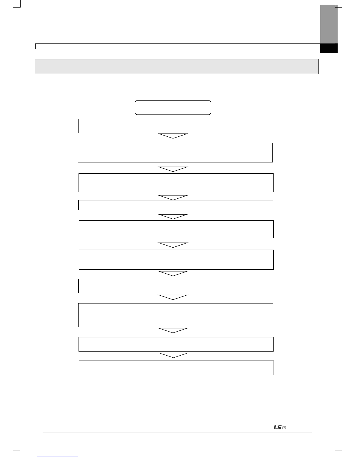
3.3 The Order for Setting up Products till Running
The following describes the order of installing or setting up products. Install the system and setting up the parameter so that
they can operate in order.
Start
● Check out the sizes and standards to be used
● Install the module to the base
● Check out the location of the base and the slot
● Check out the LED state of a communication module after power is authorized. (RUN:
Green)
● Connect to CPU using XG5000
● Carry out “I/O Sync” in XG5000
● The module appears in project window after executing “I/O Sync”
● Set up the basic parameter
▶ IP Address, Subnet Mask, Gateway
● Install the necessary EDS file
● Set up EIP parameter
▶ Channels, Functions, Starting Conditions, Data Sizes and Areas, Ty pes
● Execute “Write Parameter” and “Enable Link”
● Execute EIP communication

Chapter 3 Installation and Trial-Run
3-4
3.4 Available device area
Available device areas for each basic unit are as follows
CPU type Area Range
Size
(word)
Reference
XBC/
XBM
P
P0~P127 128 Read/Write/Monitor available, XBMS
P0~P1023 1024 Read/Write/Monitor available, XBCH, XBCS, XBMH
P0~P2047 2048 Read/Write/Monitor available, XBCU
M
M0~M255 256 Read/Write/Monitor available, XBMS
M0~M1023 1024 Read/Write/Monitor available, XBCH , XBCS, XBMH
M0~M2047 2048 Read/Write/Monitor available, XBCU
K
K0~K2559 2560 Read/Write/Monitor available, XBMS
K0~K4095 4096 Read/Write/Monitor available, XBCH , XBCS, XBMH
K0~K8191 8192 Read/Write/Monitor available, XBCU
F
F0~F255 256 Read/ Monitor avail able, XBMS
F0~F1023 1024 Read/ Moni tor avail able, XB CH, XBCS, XBMH
F0~F2047 2048 Read/ Monitor avail able, XBCU
T
T0~T255 16 Read/Write/Monitor available, XBMS
T0~T1023 64 Read/Write/Monitor available, XBCH, XBCS, XBMH
T0~T2047 128 Read/Write/Monitor available, XBCU
C
C0~C255 16 Read/Write/Monitor available, XBMS
C0~C1023 64 Read/Write/Monitor available, XBCH, XBCS, XBMH
C0~C2047 128 Read/Write/Monitor available, XBCU
L
L0~L1279 1280 Read/Write/Monitor available, XBMS
L0~L2047 2048 Read/Write/Monitor available, XBCH, XBCS
L0~L4095 4096 Read/Write/Monitor available, XBCU, XBMH
N
N0~N3935 3936 Read/Write/Monitor available, XBMS
N0~N5119 5120 Read/Write/Monitor available, XBCH
N0~N10239 10240 Read/Write/Monitor available, XBCU, XBMH
D
D0~D5119 5120 Read/Write/Monitor available, XBMS
D0~D10239 10240 Read/Write/Monitor available, XBCH, XBCS, XBMH
D0~D19999 20000 Read/Write/Monitor available, XBCU

Chapter 3 Installation and Trial-Run
3
-5
U
U0~U255 256 Monitor available, XBMS
U0~U351 352 Monitor available, XBCH , XBCS
U0~U383 384 Monitor available, XBCU
Z Z0~Z127 128 Read/Write/Monitor available
R
R0~R10239 10240 Read/Write/Monitor available, XBCH , XBCS
R0~R16383 16384 Read/Write/Monitor available, XBCU
XEC
I IW0.0.0~IW15.15.3 1024 Read/Write/Monitor available
Q QW0.0.0~QW15.15.3 1024 Read/Write/Monitor available
M
MW0~MW8191 8192 Read/Write/Monitor available, XECH, XECS
MW0~MW16383 16384 Read/Write/Monitor available, XECU
R
RW0~RW10239 10240 Read/Write/Monitor available, XECH, XECS
RW0~RW16383 16384 Read/Write/Monitor available, XECU
W
WW0~WW10239 10240 Read/Write/Monitor available, XECH, XECS
WW0~WW32767 32768 Read/Write/Monitor available, XECU
U
UW0.0.0~UW0.11.31 384 Monitor available, XECU
UW0.0.0~UW0.15.31 512 Monitor available, XECH, XECS
Notice
1) F Device: Writeable address is F220 or later .
2) In case of XBL-EIPT V2.0 or later: XEC type can only use I, Q, M, R, and W devices as EIP v ariable in global variable.
3) T / C is a timer / counter devic e. Bit designation m eans contact v alue and Word designation means current v alue.
4) XBMS, XBMH type does not support R device.
5) In U device, the addre ss of bit area is hexadecimal (Hex) value an d the address of word area is de cimal value.

Chapter 3 Installation and Trial-Run
3-6
3.5 Installation of Products
3.5.1 Installation of XBL-EIPT
[Figure 3.6.1] How t o Install 100BASE-TX
The maximum segment distance of 100BASE-TX reaches 100m. (The distance between modules)
Straight cables and cross cables are used.
If a cross cable is used when connected between these communication modules, the time for connecting links can be
shortened.
This module doesn’t support a ring system.
When configuring a ring form, IP address switch of a module – front view must be set up at ’99.’
Then, a ring system is formed in external aspect, but the service for a ring system will not be supported.
If IP address switch is not set up at 99’after formed in a ring , data burst may happen and modules can not execu te
normal actions.
Pin NO. Signal
Straight Cable between
Cables
1:1 Cross Cable
1
TD+
1-1
1-3
2
TD -
2-2
2-6
3
RD+
3-3
3-1
6
RD-
6-6
6-2
4,5,7,8
Not used - -
Notice
1) 100BASE-TX cable is designed to be weak in cable structure, so only if cables are twisted (Two
wires are stranded) after No.1 (TD+) and No. 2 (TD-) wires are twisted and No. 3 and No. 6 are
twisted with each other. wiring will be strong in strength.
2) For cable terminal treatment and manufacture, consult with professional providers to install
8 Pin - RJ45 Plug
Twist Pair Cable

Chapter 3 Installation and Trial-Run
3
-7
1) How to Inst all UTP
(1) For reliable transmission of 100Mbps signal using UTP cables, Patch Cord, Line Cord, Patch Panel, DVO(Data
Voice Outlet), etc must meet 5 spec (Category 5 Spec.- EIA/TIA-568A).
(2) Make sure the length of patch c ode will be over 7m in cross-connect, If the length exce eds 7m, the length
corresponding to 90m, as much as the allowable value in Horizont al Distri bution Sy stem, must be deducted.
(3) Make sure the length of line cord does not exceed 3m in line cord length. If the length exceeds 3m, as much as
the length corresponding to 90m, the allowable value in Horizontal Distribution System, must be deducted.
(4) Make sure the loose of paired pitch of U IP cable in cas e of disco nnection to patc h panel and D VD does not
exceed the following dimension.
(5) Maximum Paired Pitch – Loose : Category 5 : 13mm, Category 3 : 26mm
(6) Use jumper wires in DC cross-connect system. Then, also the loose of paired pitch must not exceed the above
standards. Es peci a ll y, in case of serio usl y b e nd in g c a bles , pay attention so t ha t d am ag e or s e parati on b etween
pairs does not happen.
(7) Maximum Curvature Diameter : 4 Pair Cable : 4 times the Diameter
Cable more than 25 Pair: 10 times the Diameter
(8) Make sure the maximum tensile force while using does not exceed 110N (11.3Kgf) based on 4 Pair
(9) Make sure jumper cabl es and patch cod es are loos ely disco nnected. W hen tig htly connect ed, the f eatures of
category 5 may low er. When using Tie-wrap, make sure cables are not stressed.
(10) Make sure proper distance is maintained between EMI source and UTP cable when installing cables.
The proper distance in each case is as follows.
Conditions
Minimum Separation Distance
Less than
2.0KVA
2.5 KVA
More than
5.0KVA
In case unshie lded po wer l ines or e lectr ic fac ilit ies are op en
and are in th e state of being closely located nearby non-
metal pipes
127mm 305mm 610mm
In case unshield ed po wer lines or e lectric facilities are in
the
state of being located nearby buried metal pipes
64mm 152mm 305mm
In case buried metal pipes the power line (
or the same
shields)
are in the state of being loca te d ne ar b y bur ie d metal
pipes
- 76mm 152mm
Notice
1) In case voltage reaches 480V and electric power source reaches more than 5KVA, separated calculation is required.

Chapter 3 Installation and Trial-Run
3-8
3.6 Trial- Run
3.6.1 Directions when Configuring Systems
1) To use P2P service including this module, make sure IP Addresses of all stations are different from IP addresses of
all other stations.
2) To use comm unication cables, select the on es in designated si zes. Using cables that have not been designate d
may cause serious communication obstacles.
3) Check out whether cables are disconnected or short-circuited before installing communication cables.
4) Completely tighten the connectors of communication cables so that cable connections can be fixed.
5) Incomplete cable connections may cause serious obstacles to communication.
6) In case of connecting comm unication c ables to a long distanc e, make sur e cables ar e not separated f rom po wer
lines or inductive noises.
7) Coaxial cables are low in f lex ib i li t y, so they must be re-branched lo wering down at least more than 30 cm f rom t he
connector in communication module, and if cables are bent on the square and forcibly transformed, it may cause the
destruction of the connector located in the communication module.
8) In case LED does not normally operate, refer to ‘Chapter 10 Troubleshooting’ and check out causes. If something
is wrong ev en if actions have been taken, contact Warranty Service Center.

Chapter 4 System Configuration
4
-1
Chapter 4 System Configuration
XGB EtherNet/IP I/F modules can be installed on the XBC CPU modules. The number of maximum installments reaches 2 .
It is possib le for the communication system using this modu le to be applied to a variety of configurations. This chapter
describes the examples of the cases w hen system configuration is available and unavailable by applications.
4.1 Configuration of a Usable System
4.1.1 System Configuration using a Switch
4.1.2 System Configuration not using a Switch

Chapter 4 System Configuration
4-2
4.2 Configuration of an unusable System
4.2.1 System Configuration using a Switch
It is impossible for EtherNet/IP I/F module to normally operate as data burst happens when each module is connected
to each switch of 2 communication ports.
4.2.2 Configuration of a Ring System (Configuration of a XBL-EIPT Ring)
EtherNet/IP I/F does no t support a ring system. When you configur e a ring form, it is necessary t o set up the IP
address switc h of the m odule – front vie w at ’99 .’ Then, it is co nfigure d into a ring system in exter nal aspect , but the
service on an actual ring system is n ot supported. In c ase I P addr es s switch is not set up at N O . ‘99’ after configured
into a ring, data burst happens and the module does not normally execute operations.
Chapter 5 Installation of Software and communication Parameters
5-1
Chapter 5 Installation of Software and Communication Parameters
5.1 Installation and Execution of Software
To use software XG5000, it is necessary to i ns tall XG5000. Then, XBL-EIPT V1.x should use X G50 00 V3.1 or later, XBL-
EIPT V2.0 or later should use XG5000 V4.21 or later. The requirements for system needed to execute are as follows.
1) PC and Memory: It is nec es sary to need a computer wit h more than 128MB m em ory and the memor y with more
than 512MB is recommended.
2) Communication Port: RS-232C serial port or USB po rt are req uired.
3) Hard Disk: The area where more than 200MB is possible to use is required.
4) Mouse: A mouse that can be connected with a computer is required.
5) Monitor: The resolution must reach more than 1024 X 768.
6) Window: It is possible to execute in Window 2000/XP/VISTA. However, if several app lications inc luding other
products are executed, XG5000 can be on the blitz due to the restriction to using memories.
5.1.1 Installation of XG5000
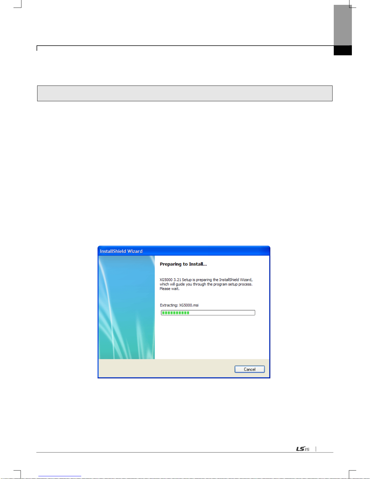
1) Execute the installation file.
2) InstallShield Wizard prepares for installation as follows.

Chapter 5 Installation of Software and communication Parameters
5-2
3) Click [Next] button.
4) Insert a company’s name and press [Next] button.
5) Designate the folder t hat XG5000 wi ll be instal led. If you wan t to change th e folder, click [Browse] and enter or
select new folder. As XG5000 needs installation space of 500MByte, select t he disk with enough room. If the
installation room is not enough, warning message is on and thus, it is impossible to proceed to next step.
6) If you have selected a folder, press [Next] button.

Chapter 5 Installation of Software and communication Parameters
5-3
7) Check out the installation path and p ress [Next] button. Install as follows.
XG5000 USB device drive install screen appears while installing, and soon, installation is completed as follows.

Chapter 5 Installation of Software and communication Parameters
5-4
5.1.2 Installation of USB Device Drive
When you install XG5000 into Window XP for the first time, install USB Device Drive additionally. Even if USB is not
connected, install USB device drive as follows.
However, in Window 2000, USB device drive is automatically installed when XG5000 is installed, and in Window XP, install it
additionally.
1) Check out whether there are driver folders in the folder XG5000 has been installed into. In Drivers folder, there are
two drive files - GmUSBD.sys, GmUSBD.inf. If there is no folder or drive file, install XG5000 again.
2) Turn on PLC power and connect USB connector to PC. When connected, new hardware search Wizard Dialogue
Box appears
3) Order a user to install the device drive.
4) Select [Install from a list or specific location (Advanced)] of the options in new hardware search wizard dialogue box
and press [Next] button.

Chapter 5 Installation of Software and communication Parameters
5-5
5) Select [Search f or the best driver in these locations] of drive searc h options and c heck out [Include this locati on in the
search]
6) Press [Browse] button
Select Drivers Folder where XG5000 has been installed in “Browse for Folder”

Chapter 5 Installation of Software and communication Parameters
5-6
7) Press [Ok] button. The computer searches for the folder you selected.
8) If the computer selects the most suitable device drive, it will ask to install the device driver selected. As USB device driver
stably operates in Window operating system, press the button [Continue].
9) The com pletion of a d evice driver is completed; the dialogue box for installation like this appears. If you press
[Finish] button, driver installation is terminated.

Chapter 5 Installation of Software and communication Parameters
5-7
5.1.3 Confirmation on the Installation of USB Device Driver
If USB is not connected, confirm the installation of device driver as follows.
(1) Click the right button in [My Computer] on the desktop and select menu [Manage].
1) The computer managem ent dialogue box appears like this . In the left tree list of the dialogu e box, extension
proceeds in this order - [Computer Management (Local)] - [System Tool ] - [Device Manager].
2) The items appearing in th e list can differentl y come out with each ot her according to the devices installed in the
computer.

Chapter 5 Installation of Software and communication Parameters
5-8
(1) In case of normal state
If the list [LSIS XGSeries] located in the lower of [Universal Serial Bus controllers] appears, the device driver has
been normally installed.
(2) In case of abnormal state
The following illustration appears, it is the case the device drive has not normally been installed.
In case of not normally installed, reinstall according to the following order.
(3) Click the right button in the device driver where “Exclamation Mark” appears.
(4) Select Menu [Update Driver]

Chapter 5 Installation of Software and communication Parameters
5-9
(5) Hardware Update Wizard Dialogue Box appears. Select Option [Install from a list or specific location
(Advanced)] List and press next button. The following procedures are manual and are the same to the installation
of the device driver.

Chapter 5 Installation of Software and communication Parameters
5-10
If not installed, reinstall according to the following order.
(1) In case a device driver has been wrongly installed or is problematic, execute Hardware Update Wizard Start.
(2) Select Option [Installation from a List or a specific location (Advanced)] List and press next button.
(3) On search and installation options, select [Don’t Search. I will choose the driver to install.] an d click [Next].
Chapter 5 Installation of Software and communication Parameters
5-11
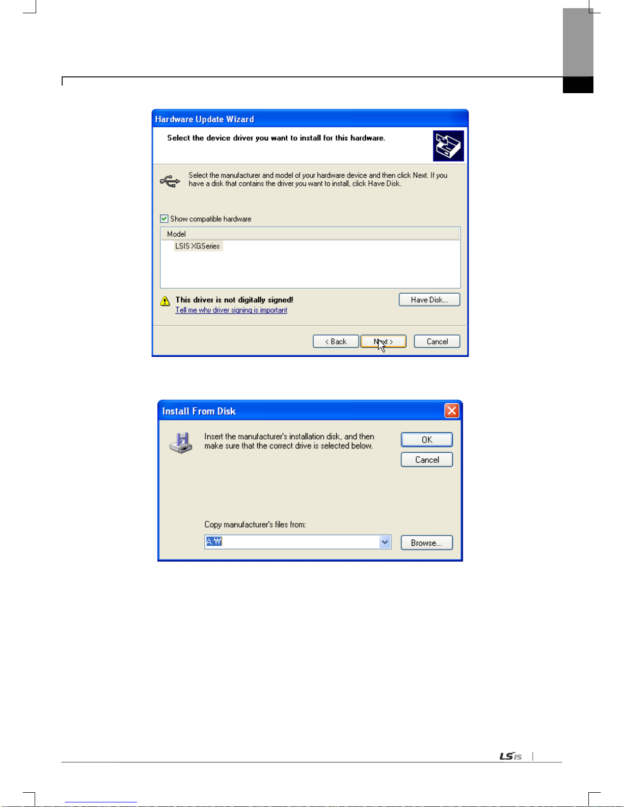
(4) Click [Have Disk…] on the Dial og Box below.
(5) If Installation Dialogue Box appears from the disc appears, press button [Browse.]
Chapter 5 Installation of Software and communication Parameters
5-12
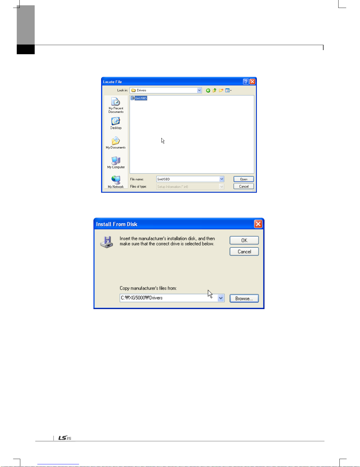
(6) Move to the folder Fi le XG5000 has been installed f rom File Search Dialog ue Box. If drivers fold select ed,
GmUSBD.inf file appears. Select this file and press button [Open.].
(7)The directory with device driver files appears on the location of the manufacture’s file. Press button [Ok.].

Chapter 5 Installation of Software and communication Parameters
5-13
(8) On the compatible H/W display list of the device driver Select Dialog Box, select “LSIS XGSeries” driver and
then click [Next] button.
(9)The Dialogue Box for Hardware Installation appears. Press button [Continue] and proceed with installation.

Chapter 5 Installation of Software and communication Parameters
5-14
(10)Dialogue Box for Hardware Update Wizard Completed appears. Press button [Finish] and complete the
installation of device drive.

Chapter 5 Installation of Software and communication Parameters
5-15
5.2 How to Register Communication Modules
To use Ethernet/IP I/F modu le, communication parameter m ust be made up in XG5000 and to set up the s ystem on
Ethernet/IP I/F module, the module must be registered to XG5000.
How to register Ethernet/IP I/F module located at discretion is as follows in accordance with the state of on/off line.
5.2.1 In case of Offline
This is the way used in setting up communic atio n modules an d makin g up comm unicatio n related parameters in the
state of not connected with PLC. The execution method is as follows.
1) After execute XG5000, select [Project] [New Project ] o r cli ck ( ).
2) Create the projects that you will store in the project name, and select the names of the projects to be stored and the
CPU types of PLC that you selected.
3) If you register a communication module without connected to PLC, Use a “Communication module setting” window.
If Ethernet/IP is to be registered on base 0 and slot 1, Set it in the following procedure at a project Window.
a) Right click [unspecified Network] -> [add item] -> [Communication module]
[Fig 5.2.4] Select communication module menu
b) Click [Select communication module] -> [Add module]

Chapter 5 Installation of Software and communication Parameters
5-16
[Fig 5.2.5] Add module
c) [Communication module settings] -> select module type, base, slot
[Fig. 5.2.6] Communication module setting
Ethernet/IP module is registered on Slot 1 of Base 0 is as shown below;
[Fig. 5.2.7] Manually register communication module

Chapter 5 Installation of Software and communication Parameters
5-17
5.2.2 In case of Online
To register the communication modu le in online state, using XG 5000, the methods in NO . 1 and NO. 2 are t he s am e
as the one in registering modules of EtherNet/IP in offline state. The execution order afterwards is as follows.
1) If not connected, check out the state of connection with PLC or select [Online ]-> [Connection Set-up], or select the
connection met hod by clicking ic on . As a connection m ethod, there is a m ethod using RS-232C, a m ethod
using USB cables, and a method using Ethernet module and EtherNet/IP module. As a connection method, select
Local in case of directly connecting with PLC. The remote connection steps will be described in 7.4 remote
connection.
2) When normally connected, the lower menus of online menus are activated.
3) To check out the m odules installe d to the curr ent main unit, se lect [Online] [Diagnosis] [I/O information …],
communicatio n modules existing in the main unit are automatically searched for and the information of installation
modules appears on the project window. In case the module r egistered in offline state are different f rom the
information of PLC currently connected or kinds of communication modules, check out whether they have
changed or not with the above message.
4) The list of the communication module installed to a product is created on “Project Window.”

Chapter 5 Installation of Software and communication Parameters
5-18

Chapter 5 Installation of Software and communication Parameters
5-19
5.2.3 In case of Reading Parameter stored in PLC
The method for reading the basic set-up values for the communication module stored in PLC and for reading P2P setup values are in the below order.
1) Select [Project.] [Open from PLC…] or click ( ).
2) It is possible to check out the basic set-up values and P2P set-up values stored in PLC.

Chapter 5 Installation of Software and communication Parameters
5-20
5.2.4 How to Set-up Modules
T o operate EtherNet/IP I/F modules, set up in the following order.
1) Execution Order
(1) Enter in the Project Window
Please refer to 5.2.1 In case of Offline.
(2) I/O Information – Read
Please refer to 5.2.2 In case of Online
2) Operation Check –out
(1) Select [Online] → [Communication module setting] → [System Diagnosis] or click icon ( ).
(2) C lick the r ight butto n of the m ouse in the m odule of the ‘System Diagnosis ’ Window and c heck out whether
communication has been in normal state or not after c licking [Detailed Module Information…] or [Status By
Service…].

Chapter 5 Installation of Software and communication Parameters
5-21
5.2.5 Menu bar and shortcut of XG5000
The following is menu bar and short cut of XG5000. (For other menus, refer to XG5000 User’s Manual)
Menu bar
Menu
Icon
Contents
Project
New Project
Creates a new project.
Open Project
Opens the existing project.
Open from PLC
Uploads the pr oject and program stored
in PLC.
Open KGLWIN File
Opens the project file for KGLWIN.
Open GMWIN File
Opens the project file for GMWIN.
Save Project
Saves the project.
Save As
-
Saves the project as a different name.
Close Project
Closes the project.
Save as Binary
Saved as the b inary file that cannot show
the details of the project.
Write Binary to PLC
Writes the binary file with the PLC. You
cannot see the details of the project.
Add Item
Adds a new item to the project.
Import Item from File
Imports a ite m fro m a separated file.
Export to File
Saves the selected items included
opened project as separated file.
Save
Variable Names to
File
Saves variable names to file for using
other programs.
Save EtherNet/IP Tags to
File
Registers Eth er
Net/IP tag and sav es the
established EtherNet/IP tag list to the file.
Compare Projects
Compares two proj ects
stored in PC and
displays its result.
Print
Prints the active window’s details.
Preview
-
Previously displays the screen to be
printed.
Print Project
-
Selects the project item to print
Print Setup
-
Sets the printer options.
Edit
Undo
Cancels the edit on Program Edit Window
to recovers its previous status.
Redo
Recovers the ed it cancel led above.
Cut
Copies the selec ts block to c lipboard an d
deletes the block.
Copy
Copies the selects block to the clipboard.
Paste
Copies from the clipboard onto Edit
Window.
Delete
Deletes the selected block or items.

Chapter 5 Installation of Software and communication Parameters
5-22
Menu bar Menu Icon Contents
Online
Connect/Disconnect
Connects or disconnects with PLC.
Connect Settings
Specifies the c onnection method.
Change Mode Changes PLC mode.
Read
Reads parameter/program/comment from
PLC.
Write
Writes parameter/progr am/comment on PLC.
Compare with PLC
Compares the project to the project saved in
PLC
Set Flash Memory -
Shows the window for setting up the flash
memory.
Communication Module
Setting
Sets up Link-Enable and Upload/Download
EIP Tag
Reset/Clear Reset the PLC or Clear all memory
Diagnosis
Shows up the PLC information or history
windows
Tools
T emperatur e control
Executes the XG-TCON tool.
Position control
Executes the XG-PM tool.
Address calculator Executes the address calculator .
Star t simulator
Starts the simulator.
ASCII Table Displays the ASCII code t able.
Customize Users define tools, commands .
Options -
Can change the XG5000’s environment for a
user.
EDS
Register or delete the EDS file used for
EtherNet/IP module
N Configurator
Executes the N Configurator tool

Chapter 6 EIP Service
6
-1
Chapter 6 EIP Service
6.1 EtherNet/IP Communication Method
The communica nt methods of EtherNet/IP are div ided into Implicit Communica tion Method and Explicit Comm unication
Method and each method is again divided into client and server function. In XGB EtherNet/IP IF module, Implicit
communication m ethod is prov ided by period ic client /period ic server and explicit commu nication metho d is provided b y
aperiodic client/aperiodic server.
The periodic client/server is similar to th e h ig h s pee d link of the existing XGT communication ser vic e, which is the service
used when data is tr ans mitted and recei ve d p er iodically. The aperiodic client/s er v er m eth od is t he communication m eth od
used when particul ar e vents ha pp en . I n XGB EtherNet/IP I/F module these two services ar e inc orporated into EIP ser vice
and provided.
6.1.1 EtherNet/IP Terms
1) Implicit Messaging: Suggestive message, the m essage where t he header information oth er than data has been
implicate d to the min imum (In XGB EtherN et/IP I/F module the m essage is provid ed via client /per iodic server
communication)
2) Explicit Messaging: Clear message, including all information that can translate frames besides data
(In XGB EtherNet/IP I/F module the message is provided via aperiodic client communication)
3) Client: The subject requiring information
4) Server: The subject that provides information at request
5) Producer: The entity that create producers, information
6) Consumer: The entity that receives consumer information and consumes it
7) Tag: Nameplate , Named Variable
8) EDS File: The abbre viation for Electric Data S heets. The file where the inf ormation on the device and on the
communication set –up is recorded
9) RPI: The abbreviation for Requested Packet Interval, meaning the period when Packet will be sent
(In XGB EtherNet/IP I/F module, pac ket is provided at transmission period)
6.1.2 EDS File
Electrical Description Script (EDS) File is a description on devices and it includes the information about a product type
and connect ion, as well as Vendor ID. In Et herN et/I P I/F module it is the b asic pr incip le t o s et up us ing EDS Fi le. To
install EDS Fie, EDS register menu of XG5000 should be set up.

Chapter 6 EIP Service
6-2
6.1.3 Periodic Communication (Implicit) System
Implicit Message provided in periodic communication in XGB EtherNet/IP I/F module means a suggestive and implied
message. As this m essage c ontai ns head er i nform ation to t he m inimum exc ept for t he data in f rame, it als o refer s to
the message which is im poss ible t o see what da ta means. In addit ion, if we trans la te it in differe nt way, this message
means that header information is small in quantity, so the process of translating the frame has been simplified and it is
possible to process data quickly. In EtherNet/IP, connection between client and server is set up with the parameter for
sending this da ta.
Client requires connect ion and it bec om es the object t ha t recei ves an d cons um es data, and s ev er com es to tr ansm it
the said data in tra nsmission period ( Re qu es t ed P acket Interval: RPI) and communication method (Unicast/Multicast)
like the way client wants Thus, client comes to set u p consumed tag and server w ill set up produced tag (XGT
EtherNet/IP IF: Input Only Type).
[Figure 6.1] Client and Server in XGT EtherNet/IP I/F - Module Periodic Communication
Notice
Implicit Server is created also in Implicit Client. Server can set up timeout in the period that client grants according to types.
Using data that client provides, it is possible to output to his own module .

Chapter 6 EIP Service
6
-3
Operating procedure of periodic communication is as follows.
Client
Time
①
Connection request
(
SYN)
Time
②
Connection request
response
(
SYN ACK
)
③
Connection confirm
response
(
ACK
)
④
Request
(PUSH ACK
)
⑤
Request
(
PUSH ACK)
⑨
Disconnection request
(
FIN ACK)
⑩
Disconnection confirm
(
ACK)
⑪
Disconnection
(
RST)
Server
Destination port
:
44818
Connection
Disconnection
Connection
Disconnection
Session register
request
Native Session ID
response
Receiving port:
44818
●
●
●
⑥
Request
(
PUSH ACK)
⑦
Reponse
(PUSH ACK)
ForwardOpen
request
T2
O, O
2T
Connection ID
response
⑧
O2
T IO Data
(O2
T Connection ID)
Source port: 2222
Destination port
:
2222
(
UDP)
⑧
T2O IO Data
(
T2O Connection ID
)
Source port
: 2222
Destination port:
2222
(
UDP)
[Figure 6.2] Operating procedure of periodic communication

Chapter 6 EIP Service
6-4
6.1.4 Aperiodic Communication (Explicit) System
Explicit Messa ge provided in aperiod ic communication from XGB EtherNe t/IP I/F module means clear a nd explicit
message. This mess ag e a ls o m eans t h at all inf ormation which is poss i bl e to tr ans lat e da ta to dat e frame. Thus, even
though it takes some time to translate frame, if the message we want is sent without the process of setting parameter,
frame is translated from server and the response is made.
In general it is utilized as monitoring data to aperiodic data rather than control data.
The following table shows the parameter items set up when XGB EtherNet/IP I/f module is used.
Inferior
Configuration
Set-up Items Set-up Scope
Set-up or Not
Remarks
Periodic
Client
Periodic
Server
Aperiodic
Client
EIP
Configuration
- O X X
Drag & drop from EDS File
EIP Channel
-
0-15 X O
O
Set up other’s IP
EIP Block Channel 0-15
O O O
Enter the channel y ou will use of set up
channels in EIP channel
Operation
Mode
Pursuant to
EIP Channel
O O O
Automatically displayed in accordance
with set up channels
I/O Ty pe Defined in
EDS
O X X
Select I/O type defined in EDS
Connection
Type
Multicast,
Point to Point
O X X
Select one among connection types
defined in EDS
Function Write, Read,
Tag Read,
T ag Write
X X O
Select one among aperiodic client s
Parameter Parameter
item O X O
Set up the parameter defined in ED S
- In case of aperiodic client, only
read/write can be set up for read /writ e
Parameter
Contents
Defined in
parameter
X X -
Display the contents set up in the
Parameter
Mobile
Conditions
Contact Point
X X O
Set up mobile conditions
Transmitting
Period
20-10000
O X X
Period transmitting d ata
Timeout x4/8/16/32/64
/128/256/512
O X X
Transmission Period x Timeout(x4/8/16
/32/64/128/256/512)
Data Ty pe BIT,1/2/4/8
BYTE
O O O
Set up a data type
T ag Set- up/
Local T ag
PLC Device
O O O
The device area of the local axis where
“Write” or “Read” is executed you w ill
T ag Set- up/
Remote T ag
Destination
TAG name
O X O
Designate Other’s T AG
T ag Setup/Size
O O O
Periodic Client/Server : Maximum 500
Byte
Aperiodic Client : Maximum 512 Byte

Chapter 6 EIP Service
6
-5
Notice
1) Data type: The data type is the same as above table for XBL-EIPT V1.x, and the same as the registered tag type for V2.0 or later.
BOOL(BIT), BYTE, WORD, DWORD, LWORD, SINT, INT, DINT, LINT , USINT, UINT , UDINT, ULINT, REAL, LREAL types are av ailable.
The data size in V1.x i
s fixed at 1 for BIT and 2 BYTE in case of periodic server, but in V2.0 and above, size and type are the same as
registered tags.
2) T ag setting / Loc al tag: When XBL-EIPT V2.0 or later is used, tag name can be up to 38 characters for XBC/XBM and up to 46 characters
for XEC. This is th e maximum number of var iable names including t he members of the structure.
3) Tag Setting / Remote T ag: In the channel where XBL-EIPT is set as explicit client, remote tag name can be set up to 40 character s for IEC
type and 32 characters for K type. Tag name can be up to 80 characters when operated as a aperiodic server .

Chapter 6 EIP Service
6-6
Operating procedure of aperiodic communication is as follows.
Client
Time
①
Connection request
(SYN)
Time
②
Connection request
response
(SYN ACK)
③
Connection confirm
response
(ACK)
④
request
(PUSH ACK)
⑤
Response
(PUSH ACK)
⑧
Disconnection request
(FIN ACK)
⑨
Disconnection confirm
(ACK)
⑩
Disconnection
(RST)
Server
Destination port :
44818
Connection
Disconnection
Connection
Disconnection
Session register
request
Native Session ID
response
Receiving port: 44818
●
●
●
⑥
request
(PUSH ACK)
⑦
response
(PUSH ACK)
TAG read/write
read/write
request
TAG read/write
read/write
response
[Figure 6.3] Operating procedure of aperiodic communication

Chapter 6 EIP Service
6
-7
6.2 EIP Service
EtherNet/IP is divided into a periodic message service (Implicit Service), and an aperiodic message service (Explicit
Service). In XBL-EIPT module these t wo services are incorporat ed to be prov ided as period ic/client server and a periodic
client.
In Periodic Client / Server Service, the tag for communication must be set up in parameter system. Thus, client and server
tag m ust be s hared with information for comm unication when parameter is ex changed. In XG B EhterNet/I P I/F module,
client and server must be set up with XG5000. Make sure client is set up in periodic client and sever is set up with periodic
server. For the detail contents, see CH 6.3.
Aperiodic client service must be communicated after you put the tag to be communicated and communication set-up. Thus,
when required from clie nt, server r eceives al information in fram e and trans lates, and r esponds. In other words , it is t he
service without setting up from server side.
In this part, EIP types and use methods provided to a user are described.
The flowing refers to the order for making up the program using EIP.

Chapter 6 EIP Service
6-8
6.3 T ag setup
6.3.1 XBC/XBM
For XBC/XBM, you can set up the tag in [Save EtherNet/IP Tags to File…] of the project menu. For more details, refer
to the below setup procedures.
1) [Projext] [Save EtherNet/IP Tags to File…]
2) In the Setting EtherN et/ I P var ia b le w indow, set the EtherNet/IP variabl es via [New Variable]. Variable name (local
tag) length is maximum 38 characters. If you select [Save] button, you can save the set variable.
Notice
1) XG5000 does not provide a function to load saved t ags.

Chapter 6 EIP Service
6
-9
6.3.2 XEC
When you appl y XEC, you can set up tags i n th e “g lo ba l/ direct variables” of XG5000 proj ect and tick the checkbox of
EIP for setup. For more details, refer to the below setup procedures
1) [Project] [Global/Direct Variables]
2) Declare the variable to be used as tag in XG5000. Variable n ame can be up to 46 char acters, i ncluding the
members of the structure
3) Tick the EIP Check Box to be used in EtherNet/IP.
4) Save it a s the [Project] [Save V ariable Names to Files…].
Notice
1) XG5000 does not provide a function to load saved t ags.

Chapter 6 EIP Service
6-10
6.3.3 Supported Device by Main Unit
Supported Devi ce
XBC/XBM
XEC
BIT (BOOL)
O O BYTE O O
WORD O O
DWORD
O
O
LWORD
O O SINT O O
INT O O
DINT O O
LINT O O
USINT O O
UINT O O
UDINT O O
ULINT O O
REAL O O
LREAL O O

Chapter 6 EIP Service
6
-11
6.4 Setup of Periodic/Non-periodic Communication Service
6.4.1 Periodic Client Communication Service
After setting the com m unica tion m odu les an d bas ic param eters with X G50 00, us e the m ous e to dra g the ED S file of
the opposing station to be communicated and start setup
1) Basic Parameter Set - up and EDS Register
Order
Set-up
Procedure
How to Set up
1
Communication
Module Set-up
1) In Network Configuration, right click on the Unspecified Network and select "Add Item" -> "Communication
Module".
2) Click the "Add Module" button in the "Select Communication Module". Select XBL-EIPT as the type in the
communication module setting window and select the base and slot where XBL-EIPT is installed.
3)
Double-click the comm unica tion mod ule t o set t he b asic param eter s. At th is tim e, if XBL-
EIPT is Ver2.0 or
later, use tag should be checked.

Chapter 6 EIP Service
6-12
Order
Set-up
Procedure
How to Set up
2
EDS File
Register
1) Register the EDS file of the communication module you want to set up.
2) Click ‘XG5000 -> EDS information window’
3) Right-click on the EDS information window and a pop-up menu will appear as shown below.
Select “Register EDS” and select the EDS file you want to register.
4) After comp leting the above pr ocedures, you can s ee the registered E DS file in the EDS f ile information
window.
If XBL-EIPT is V er2.0 or later, use EDS Ver2.10. If XBL-EIPT is less than Ver2.0, use EDS Ver1.1.

Chapter 6 EIP Service
6
-13
Order
Set-up
Procedure
How to Set up
3
EIP Service
Register
1)
Right-click on the XBL-EIPT module for which you want to configure the service and select "Add Item" -
> "P2P
Communication".
2) Select the P2P nu mber in t he P2P selection window.
3) P2P 02 is assigned to the XBL-EIPT module installed in slot 1
Notice
P2P 01 is allocated for built-in communication, P2P 02 for the first communication module and P2P 03 for the
second communication module. However, in the case of the main unit with built-in Ethernet, P2P 02 is
assigned to the built-in Ethernet, and P2P 03 and P2P 04 are assigned to the communication module,
respectively. Keep this in mind when setti ng.

Chapter 6 EIP Service
6-14
2) EIP Configuration and Parameter Set-up
Order
Set – up
Procedure
How to Set up
1
EIP settings
1) Drag the registered EDS file from the EDS information window and paste it to the EIP configuration window.
If the relative XBL-EIPT is V2.0 or higher, select Ver2.10 from the EDS information window and select Ver1.1 if it is V1.x.
2) The channel setup window will be displayed at the same time as pasting.
3) Set up the channel number and IP address in the setup wind ow .
2
EIP Channel
Information
Check-out
1) After registration in EIP settings, it is possible to check out the information on channels in EIP channel window.
2) In periodic client communication, more set-up is not required, so the said channel becomes inactivated.

Chapter 6 EIP Service
6
-15
Order
Set-up
Procedure
How to Set up
3
EIP
Block
Set-up
1) Enter the channel number set in the periodic client and select the I/O type and connection type.
2) Click the “Parameter” to change the T ag Size and Instance.
3) How to set the Tag of EIP block depends on XBL-EIPT version
(a) For XBL-EIPT V1.x
a) Write the device address in the local tag of the tag settings.
(b) For XBL-EIPT V2.0 or later
a) Double-click on the local tag of the tag setting and the "Select EtherNET / IP T ag" window will appear.
b) Double-click the tag to set it.
c) The type of the inpu t local t ag is displ ayed in t he data type.
The following example shows how to set the tag size according to the tag type.
i) To input basic type tags such as TEST_0, TEST_1, TEST_2: Enter 1 in T2O T ag Size
ii) To input array type tags such as TEST_3: Enter the size of array in T2O Tag Size
iii) T o input a specific index of a one-dimensional array type such as TEST_3 [1]: Enter 1 for T2O T ag Size.
iv) To input a specific index of a 3-dimensional array type such as TEST_4 [1,1,0]: Enter 1 in T2O T ag Size

Chapter 6 EIP Service
6-16
1) Channel: Dra g the EDS f ile to dis play the s et chan nel. If se veral cha nnels ar e set, a us er can s elect the d esired c hanne l
number to configure the block.
2) Operation mode: It is displayed depending on the set channel; displayed as periodic client, non-periodic clien
t and periodic
server.
3) I/O type: I n dic ates th e nam e of the connect i on def i ne d in t he E DS file of the rele vant device. The com munication with the
server side will be opened based on the connection method set here.
4) Access mode: Sets up how to comm uni
cate with the ser ver. The informati on supported depending on t he module is
recorded in EDS and MUL TICAST, Point To Point(UNICAST) may be available.
5) Parameters: Means the parameters of the server side that should be set by a user. For more details on pa
rameters, refer to
the server manual.
▶ Input Only(ID): Data is provided in the T-> O direction and heartbeat is provided in the O-> T direction.
▶ Listen Only(ID):
A no n-Listen Onl y connectio n must ex ist to al low acces s. Data is pro vided in t he T-> O
direction and
heartbeat is provided in th e O-> T direction. If the non-Listen Only connection requests T-
> O path does not exist, return
an error.
▶ Exclusive Owner(ID): T-> O, O-> T Connection type that can provide data in both directions. The T arget ac
cepts only one
exclusive owner connection for the same O-> T path.
▶ Input Only(Tag): Data is provided in the T-> O direction and heartbeat is provided in the O-> T direction.
Input Only (ID)
specifies the input assembly instance of the server, whereas Input Only (Tag) specifies the tag name of the server.
i) T2O T ag Size: Number of data to read from the server side. It also appears in the Size of the Tag settings.
ii) O2T Tag Size: Number of data to write to the server side. It also appears in the Size of the Tag settings.
iii) Output Assembly Instance (8bit): Block number on the server side to write.
Generic EDS: It should be set to 150 when connecting to the periodic server set in P2P block 0 of XGB.
XBL-EIPT EDS: It should be set to 0 when connecting to the periodic server set in P2P block 0 of XGB.
(The offset is set to 150 in XBL-EIPT EDS (set value +150).)
iv) Input Assembly Instance (8bit): Block number on the server side to read.
Generic EDS: It should be set to 100 when connecting to the periodic server set in P2P block 0 of XGB.
XBL-EIPT EDS: It should be set to 0 when connecting to the periodic server set in P2P block 0 of XGB.
(The offset is set to 100 in XBL-EIPT EDS (set value +100).)
6) Parameter Contents: Displays the details of the set parameters.
7) Transmission period (ms): Means the transmission cycle of the data and the setting range is 20~10000 ms.
8) Timeout: Set the value of the integer multiple of the time set as the transmission cycle(ms) and set the time to report er
ror
when the frame does not exist within the set time. The setting range is transmission cycle ×4~512.
9) Date Type : Displays the t ag type set in the loca l tag. .
10) Local T ag: Set the area to read or write local data
In case of V2.0 or later, the size of the local tag must be the same as the Tag Size of the parameter contents.
11) Remote Tag: Input the set Producer T ag to the opposing station for the period communication

Chapter 6 EIP Service
6
-17
3) Parameter download and Link enabl e
Order
Set-up
Procedure
How to Set up
4
Write
Parameter
and Enable
Link
1) After clicking [Online] → [Write], check the set Network Parameter and click [OK].
If "Set link enable with parameter" is checked, ‘Enable Link’ setting can be made at the same time.
2) Aft er click ing [Online] → [Communication modu le setting] → [Enable L ink], check the P2P(EI P) and
click [Write]. If "Set link enable wit h parameter" is check ed, ‘Enable Li nk’ setting can be made at the
same time. If you do not check Link Enable, the set EIP will not be operated

Chapter 6 EIP Service
6-18
6.4.2 Aperiodic Client Communication Service
Aperiodic Communication is th e s er v ice to read or write th e opposing tag data. It can be used simi lar l y to X GB’s P2P
service and you can use it by setting the opposing tag data without setting EDS..
1) Basic Parameter Set-up and EIP Service Register
For basic parameter setting, refer to 1) Basic Parameter Set- up and EDS Register of 6.4.1 Periodic Client
Communication Service.
2) EIP Channel and Parameter Set-up
Order
Set-up
Procedure
Hot to Set up
1
EIP Channel
Information
Check-out
1) Set the Operation mode of EIP channel to 'Explicit Client'.
2) Input the IP address of the opposing station.
2 Block Set-up
▶
T ag Read
(a) For XBL-EIPT V1.x
(b) For XBL-EIPT V2.0 or later
▶ Generic Read
It is a function to read object information of T arget. It is necessary to know Sevice Code, Class, Instance, and
Attribute provided by T arget.
(a) For XBL-EIPT V1.x
(b) For XBL-EIPT V2.0 or later

Chapter 6 EIP Service
6
-19
3) Parameter download and Link enabl e
Refer to 3) Parameter download and Link enable of 6.4.1 Periodic Client Communication Service.
Notice
After adding two XBL-EIPTs to a basic unit and registering 32 blocks as aperiodic client for one and setting another
module acting as s er ver, if you time ho w long it tak es f or 32 blocks to be servic e d, i t is 1 .3s . So t im e t o de a l with 1
block is about 4 0ms , when r egist ering 32 b lock s, ser vice cou nt per seco nd get les s 1. So if you set s tart con diti on
fast, the service faster than 1.3 is not available.
Order
Set-up
Procedure
Hot to Set up
2
Block Set-up
▶ Example of Parameter Set-up
1) Channel: Select and use the one among those set up with aperiodic client.
2) Operating Mode: Displays the operation mode depending on the set channel.
3) Function: There are ‘Tag Read’command that reads and saves the tag data f rom the ser ver; ‘Tag Write’ command that
saves the data to the server; ‘Read/Write’ that inputs directly the parameters not tag.
4) Parameter: Can be set only when setting ‘Read/ Write’ in Functions.
▶ Service Code(Hex): Input the service code to be used. (Example.: 0E : Get ,10 : Set)
▶ Class(Hex): Input the Class to set parameters.
▶ Instance(Hex): Input the instance to set parameters.
▶ Attribute(Hex): Input the Attribute to set parameters.
5) Conditi onal fla g: Sets the operation conditions to send messages.
6) Data Ty pe:
i) For XBL-EIPT V1.x: Input the Data Type if Tag that you will set up.
ii) For XBL-EIPT V2.0 or later: If you select the local tag, the data type of the selected tag will be displayed.
7) Tag Settings
a) Local tag: Set up the client’s (own) tag.
b) Remote tag: Set up the server’s tag. The remote tag name can be set up to 40 characters for XEC and 32 characters for
XBC / XBM.
c) Size
i) For XBL-EIPT V1.x: Sets up the size depending on the data type.
ii) For XBL-EIPT V2.0 or later: If you select the local tag, the size of the selected tag will be di splayed.

Chapter 6 EIP Service
6-20
6.4.3 Periodic Server Communication Service
For the periodic communication using EtherNet/IP I/F module, even in case of the module operated by the server, you
need to set up the tag size, address.
1) Basic Parameter Set-up and EIP Service Registry
For basic parameter setting, refer to 1) Basic Parameter Set- up and EDS Register of 6.4.1 Periodic Client
Communication Service.
2) EIP Channel and Parameter Set-up
Order
Set - up
Procedure
How to Set up
1
EIP Channel
Information
Check - out
1) Set the Operation mode of EIP channel to ‘Implicit Server'.
2) The mod ule f or which t he b asic paramet ers ar e set is opera ted as the per iodic s erv er so you do no t nee d to i nput th e IP
address of the opposing station.

Chapter 6 EIP Service
6
-21
3) Parameter download and Link enable
Refer to 3) Parameter download and Link enable of 6.4.1 Periodic Client Communication Service.
Notice
When a user s ets up the module operatin g via periodic server, the index of EIP block is granted the fo llowing
meanings.
(In case of being set by other company’s client)
1. Input Assembly Instance’s start index is 100
2. Output Assembly Instance’s start index is 150
3. For example, in case index 0 is set as periodic server, Input Assembly Instance should be 100 and Out put
Assembly Instance should be 150.
4. O2T Input Only Heartbeat Instance ID is 198.
5. O2T Listen Only Heartbeat Instance ID is 199.
6. Configuration Assembly Instance ID is 197.
Order
Set - up
Procedure
How to Set up
2
Block Set-
up
▶ Example of Block Set-up
(a) For XBL-EIPT V1.x
(b) For XBL-EIPT V2.0 or later
1) Channel : Select and use the one among the channels where periodic servers have been set up
2) Operating Mode: The operation mode of the channel set up according to the channel set-up is display ed
3) Date Type
i) For XBL-EIPT V1.x: Fixed to 2 bytes.
ii) For XBL-EIPT V2.0 or later: If you select the local tag, the data type of the selected tag will be displayed.
4) Local T ag: This tag is the device area of the module operating via server.
5) Size
i) For XBL-EIPT V1.x: Input the data size of the module operating via server.
ii) For XBL-EIPT V2.0 or later: If you select the local tag, the size of the selected tag will be displayed.

Chapter 6 EIP Service
6-22
6.4.4 Aperiodic Server Communication Service
1) Basic Parameter Set-up and EIP Service Registry
For basic parameter setting, refer to 1) Basic Parameter Set- up and EDS Register of 6.4.1 Periodic Client
Communication Service.
2) EIP Channel and EIP Block do not need to be set if they only operate as aperiodic servers.
3) Parameter download and Link enabl e
Refer to 3) Parameter download and Link enable of 6.4.1 Periodic Client Communication Service.
6.4.5 Tag naming rule for aperiodic communication services
This chapter describes on how to name the tag in the client when EtherNet/IP I/F module acts as aperiodic server
When our company’s EtherNet/IP modules, XBL-EIPT or XGL-EIPT become the client, you input the tag name of the server at
the “Remote tag” in the XG5000. For one TAG READ or WRITE requ est frame, up to 64 tags are allow ed . Bu t in cas e X B LEIPT , XG L-EIPT is client, you can input on ly one ta g.
i) For XBL-EIPT V1.x
ii) For XBL-EIPT V2.0 or later
For Tag registration, refer to 6.3 T ag setup.
1) Tag type and size
For XBL-EIPT V1.x, max Read/Write count and EIP type per one tag by type are as follows..
Bit
Byte
Word
Double Word
Long Word
Max. count 1 512
256
128
64
EIP type
hC1
hC2, hC6, hD1
hC3, hC7, hD2
hC4, hC8, hD3, hCA
hC5, hC9, hD4, hCB
Notice
For XBL-EIPT V1.x: When acting as server, this is available EIP type list. Types other than them are considered as
error. Type with an underline, when XGL-EIPT, XBL-EIPT is client, is EIP type which is changed about the type set
in the XG5000. When the server responds, it responds by using the requested type.
For XBL-EIPT V2.0 or later: The registered tag type will be used as it is.

Chapter 6 EIP Service
6
-23
2) S tandard for tag naming
This information applies to XBL-EIPT V1.x.
There are 5 kinds of th e supported type ( Bit, Byte, W ord, Doub le Word, L ong Wor d). T he form at of tag nam e per
type is as follow s.
a) Bit type tag format
‘%’(1 letter)
Device name (1letter)
Type (1 letter)
Word address (at least 1 letter)
Bit address (1 letter)
‘%’
Refer to
3.4 Available device area
‘X’ or ‘x’
Refer to
3.4 Available device area
‘0’ ~ ‘F’
1) ‘%’ is not necessary item. Tag name can start from ‘%’ or device na me.
2) Both small letter and capital letter are available for device name.
3) Both small letter ‘a’ ~ ‘f’ and capital letter ‘A’ ~ ‘F’ are available for bit address.
- Valid tag name example) “PX0F”
- Invalid tag name example) “MX0” -> there have to be at least 2 letters after type
b) Byte, Word, Double Word, Long Word type tag format
%(1Byte)
Device name (1Byte)
Type (1Byte)
Word address
‘%’
Refer to
3.4 Available device area
Byte: ‘B’ or ‘b’
Word: ‘W’ or ‘w’
Double Word: ‘D’ or ‘d’
Long Word: ‘L’ or ‘l’
Refer to
3.4 Available device area
1) ‘%’ is not necessary item. Tag name can start from ‘%’ or device name.
2) Both small letter and capital letter are available for device name.
- Valid tag name example) “MW0”
- Invalid tag name example) “M0000” -> There have to be ty pe after devi ce name

Chapter 6 EIP Service
6-24
Notice
The following is EIP data type used at the XBL-EIPT which comes from CIP (Common Industrial Protocol)
certificate
C-5.2.1 BOOL Encoding
C-6.1 Elementary Data type Reporting

Chapter 6 EIP Service
6
-25
6.5 Examples
6.5.1 Communication with Rockwell 1756-ENBT Communication Module
The system configuration is as follows.
Segment
1756-ENBT
XBL-EIPT
IP Address
192.168.250.41
192.168.250.52
1. Setup of 1756-ENBT Consumer, XBL-EIPT Producer
(1) Setup of XGB Ethernet/IP I/F module parameter
XGB is used as producer so refer to the details of the above 6.4.3 to set it as periodic server
Order
Set-up
Procedure
How to Set up
1
Server Set-up
<XBL-EIPT V1.x>
<XBL-EIPT V2.0 or later>
1) Channel: Selects one among the channels set as periodic server.
2) Operating Mode: Displays the operation mode depending on the set channel.
3) Data T ype : Shows the data type of the set tag.
4) Local T ag : This tag is the device area of the module operating via server
5) Size: The data size of the module operating via server. If V2.0 or later, shows the number of selected local tags

Chapter 6 EIP Service
6-26
(2) Rockwell 1756-ENBT Communication Module and Communication Set-up
Set up Rockwell’s Client using Rockwell’s S/ W(RSLogix 5000)
Order
Set-up
Procedure
How to Set up
1
Module
Set - up
Search for the module in I/O Configuration and install it
2
Network
Module
Installation
1) If ENBT Module has been installed, extend it into network and install the module of the network connected.
2) Herein, the ins tallation of R ockwell’s module on ly is available, a nd mod ules, no t Rockwell’s one,
are possible to set up,
using Generic Device.
3) For the connection of XGT EtherNet/IP I/F Module, set up Generic Device.

Chapter 6 EIP Service
6
-27
Order
Set-up
Procedure
How to Set up
3
Network
Address and
Connection
Information
Input/
RPI set-up/
T ag set-up
1) Communication based on Assembly Instance
a) Input the IP Address and Connection Parameter.
b) Input the RPI.
i) Requested Packet Inter val (R PI): Set up the per iod of data th at a us er w ill rec ei ve from ser ver. Client
sets up on what information to get and the server adopts this set-
up, data (Produc ed Tag) will be
transmitted as the w ay set up. T hus, cli ent al lots to this
RPI parameter in h ow lon g per iod ser ver wil l
transmit.
ii) If clicking O K, parameter is downlo aded and is automat ically con nected. T hen, data com municat ion
starts.
c) When a module set up, the tag named to Controller T ags in module name is automatically s
et up, so the
check--out of d ata is c o nf irm ed in Controll er Tags. In case of b e in g set up as see n ab ov e, d ata ch eck
-
out is availabl e in EIPT: I.

Chapter 6 EIP Service
6-28
Order
Set-up
Procedure
How to Set up
3
Network
Address and
Connection
Information
Input/
RPI set-up/
Tag set-up
2) Communication based on T ag.
a) Input the IP Address.
b) Input the Producer Tag and Consumer Tag.
i) Name: Input the name of the consumer tag.
ii) Data T y pe: Input the data type to be communicated.
iii) Connection: Input the producer tag to be connected with the consumed tag.
iv) RPI: Input the transmission cycle that the producer will receive.
Chapter 6 EIP Service
6
-29
Order
Set-up
Procedure
How to Set up
3
1) Name: Input the name to be used for the module.
2) IP Address: Input XBL-EIPT module’s IP.
3) Comm. Format: Set to “None” for comm unication based on Tag. Set " Input Data -
SINT" for communic ation based on
Assembly Instance.
4) Connection Parameter: Activated when "Comm Format" is selected as "None" and enter connection parameters
.
Mapping has been done between this information and block index
number, and the number has been allotted to Consumed
T ag input by blocks and Produced T ag output, respectively. XBL-EIPT operates as server.
(a) Assembly Instance
i) In case of Input Only
- Input Assembly Instance: ‘100+P2P index number’ in Generic EDS, ‘P2P index number’ in XBL-EIPT EDS
- Output Assembly Instance: ‘198’ (Heartbeat Assembly Instance)
ii) In case of Listen Only
- Input Assembly Instance: ‘100+P2P index number’ in Generic EDS, ‘P2P index number’ in XBL-EIPT EDS
- Output Assembly Instance: ‘199’ (Heartbeat Assembly Instance)
iii) In case of Exclusive Owner
- Input Assembly Instance: ‘100+P2P index number’ in Generic EDS, ‘P2P index number’ in XBL-EIPT EDS
- Output Assembly Instance: ‘150+P2P index number’ in Generic EDS, ‘P2P index number’ in XBL-EIPT EDS
(b) Configuration Assembly Instance: 197
(c) Size : When Generic EDS, Byte unit
When XBL-EIPT Ver1.1 EDS, Word unit

Chapter 6 EIP Service
6-30
2. Setup of 1756-ENBT P roducer, XBL-EIPT Consumer
(1) Setup of XGB Ethernet/IP I/F module parameter
XGB is used as consumer so refer to the details of the above 6.4.1 to set it as periodic client
(2) Rockwell 1756-ENBT Communication setup
Y ou can set up the producer of Rockwell by using Rockwell’s S/W(RSLogix 5000).
Order
Set-up
Procedure
How to Set up
1
Set up
channel with
Generic EDS
1) Select the Generic EtherNet/IP Module in the EDS information window and drag it to the EIP configuration window.
2) IP Address: Input the IP of 1756-ENBT module.
Block setup
1) I/O type: Select 6. Input Only(T ag T ype).
2) Parameter: Input the size of the consumer tag. The size is the number of data types.
3) Local tag: Select the consumer tag to be communicated with the producer.
Order
Set-up
Procedure
How to Set up
1
Producer tag
setup
1) Name: You can input the name of the producer tag.
2) Data Type: You can input the data type to be communicated.

Chapter 7 Diagnosis Function
7
-1
Chapter 7 Diagnosis Function
This chapter describes how to check out systems and modules, how to check out network state, and how to download 0/S.
When checking out states of system configuration and EtherNet/IP I/F Module, a user should review the following procedure.
7.1 System Diagnosis
This diagnosis is the method to check out the state of EtherNet/IP I/F Module and systems. If click [Online]
[Communication module s etting] [System Diagnosis] after clic king [Online] [Connection] on XG5000, the system
diagnosis screen is open as seen in [Figure 7.1.1] and Module Information Window is open in system diagnosis below as
seen in [Figure 7.1.2].
[Figure 7.1.1] System Diagnosis Screen
[Figure 7.1.2] Module Information Window

Chapter 7 Diagnosis Function
7-2
7.2 System Diagnosis Items and Contents
1) This part describes the diagnosis items and contents of EtherNet/IP I/F Module provided from XG5000.
Order
Diagnosis
Items
How to Set up and Contents
1
System Diagnosis
1) Select [Connection] → [Online] → [Communication module setting] → [System Diagnosis]
2) Put the m ouse on XBL-EIPT and click it with the right s ide of the mouse to check out the
diagnosis information of EtnerNet/IP I/F Module a user wants.
2
Communication
Module Information
The general information of EtherNet/IP I/F Module is displayed.
1) Module Kind: Displays kinds of modules (XBL-EIPT).
2) Base No. : Displays the base location of the module installed.
3) Slot No.: Displays the slot location of the module located.
4) IP Address: Displays IP address set up in module.
5) MAC Address: Displays MAC address set up in the modules.
6) Module Status: Displays the state of the module.
7) Hardware Error: Displays whether the error of the hardware has been made or not.
8) Hardware Version: Displays the version of the hardware.
9) OS Version: Displays the version of module OS.
10) Vender ID: Vendor ID of Displays EtherNet/IP Module
11) Product Ty pe: Displays the Product Type of Ethernet/IP
12) Serial No.: Displays the serial no. of the module
.
13) Product Code: Displays the code No. of the module
14) Product Name : Displays the name of the module
15) Dedicated service: Displays when operation channel exists as aperiodic server
16) System parameter information: Displays basic parameter setting status

Chapter 7 Diagnosis Function
7
-3
Order
Diagnosis
Items
How to Set up and Contents
3
St ate by
Services
EIP
Service
1) Specific Flag Information Window
(1) Block No. : Displays the index of the parameter that a user set up with EIP Service.
(2) Channel No.: Displays the number of the channel that a user set up in each block.
(3) Service Kind: Displays the type of the service that a user set up : Implicit Client / Implicit
Server / Explicit Client
(4) Connection Status: Displays whether EIP Block has been connected or not.
▶CONNECT: State that connection has been completed
▶IDLE: S tate that connection has not been completed
(5) Block Status: Displays the block state of EIP Block
▶NONEXIST: State that the set-up of connection has not been done
▶REGSESSION: State that TCP Connection has been completed and EtherNet/IP
Connection is in the process of being set up
▶READY : State that communication is available
▶B USY : State that response on required frame has not been received yet
(6) Service Count per Second: Displays how many times the service has been carried out per 1
second.
(7) Accumulative Service Count : Displays the number of services till now
(8) Accumulative Error Count : Displays the number of errors till now

Chapter 7 Diagnosis Function
7-4
Order
Diagnosis
Items
How to Set up and Contents
4
St ate by
Services
Explicit Server
Information
1) Session Handle : The original number granted to connected client
2) IP Address : IP Address of connected client
3) The Number of RR packets sent: The Number of Transmission Packets of the Message in the
form of Request/Reply
4) The Number of RR Pack ets received: The Number of Rec epti on Pack ets of the Messa ge in
the form of Request/Reply
5) The Number of Unit Packets sent: The Num ber of Transmission P ackets of the Message
used after connection set-up
6) The Number of Unit Packets received: The Number of Reception Pac kets of the Messa ge
used after connection set-up
7) The Number of Error Packets : The Number of Error Packets coming into Server
5 Media Information
1) Service State Information: Displays the number of service completed in EtherNet/IP I/F
Module.
2) Media State Information: Displays the packet quantity per second in service type of
EtherNet/IP I/F Module.
3) Packet Monitoring

Chapter 7 Diagnosis Function
7
-5
Order
Diagnosis
Items
How to Set up and Contents
6
Ping Test
It is possible to c heck out t he operatio n state of an oppo nent countr y by enter ing an oppo nent
country’s IP Address
In case of n ot receiving th e signal fr om an opponent country, it is necessary to check out t he
basic set-up information
7
Auto Scan
A user can check out the system configuration state of the whole system.
▶ Parameter: In case EIP Parameter is set up, it is marked as P.’
▶ Active: The module operating normally (Online State) is marked as‘A.’
▶ Diagnostic: The module that diagnosis needs to be marked as ‘D.’

Chapter 7 Diagnosis Function
7-6
Order
Diagnosis
Items
How to Set up and Contents
8
System
Log
In case a user cannot check out the performance of errors and services or stores the contents of
the current memory area into flash, when pressing the Log switch, memory area log is
automatically stored to flash.
1) Memory Area Log: Displays the history when errors and the problems in service performance
are made.
In case of Memory Area Log, when the power is turned off, it automatically extinct.
2) Flash Area Log: When a user presses the log switch on the module’s front side, the log of the
memory area is s tored into memory, and even if the power is turned off, th e history can be
maintained.

Chapter 7 Diagnosis Function
7
-7
2) NDR flag condition according to service type
Channel
Operation Mode
Flag condition
Remark
Explicit C lient -
NDR = 1
NDR = 0
Cleared to 0 each time the Conditional flag is On, a
nd
set to 1 i f a normal response is received
Implicit C lient
O2T
NDR = 0
Cleared to 0 every Transmission period
T2O
NDR = 1
Set to 1 each time it is received
Implicit Server
connected with O2T
NDR = 1
NDR = 0
Before connecting:
Cleared to 0 every second
After connecting : Clear ed to 0 ever y secon d, and s et
to 1 each time it is received
connected with T2O NDR = 0
Before connecting:
Cleared to 0 every second
After connecting: Cleared to 0 every T2O period
connected with T2O, O2T
NDR = 1
NDR = 0
Before connecting:
Cleared to 0 every second
After connecting: Cl ear ed to 0 e ver
y T2O period, and
set to 1 each time it is received
3) Service count condition according to service type
Channel
Operation Mode
Service count c ondition
Explicit C lient -
Service count is incremented by 1
when a response to the
request is received
Error count is incremented by 1 when an
abnormal
response is received
Implicit C lient
O2T
After connection, s ervice count is incremented b y 1 a
fter
transmission for every O2T period
T2O
After connection , service count is incremented b y 1
each
time it is received
Implicit Server
connected with O2T
After connection , service count is incremented b y 1
each
time it is received
connected with T2O
After connection, s ervice count is incremented b y 1 after
transmission for every T2O period
connected with T2O, O2T
After connection, s ervice count is incremented b y 1 after
transmission for every T2O period
, and is incremented by 1
each time it is re ceived
Notice
1) NDR Flag: It is a communication flag according to P2P service setting. Normally, it is On when P2P service normally processes the
corresponding block, but it depends on serv ice type in case of EIP.
2) P2P parameters are 1 ~ 3, and P2P blocks are 0 ~ 31. For the detailed config uration, refer to the N DR flag in the flag list in A ppendix A.2.

Chapter 7 Diagnosis Function
7-8
7.3 Troubleshooting
This part describes causes and actions on failures and errors that may happen in operating systems. When a user wants to
check out errors and problems in EtherNet/IP I/F Module, the following procedure will help you check out those
malfunctions. W hen judging wh ether the module is in abnormal state or not, m ake sure to take ac tions in order, using
Troubleshooting. Do not repair and disassemble at your discretion.
7.3.1 Check-out through LED in Communication Module
This check-out is the way of checking out the state of the module to see whether it is defective or not.
1) Abnormal Operation Display
LED located on the front side of EtherNet/IP I/F Module enables a user to check out.
[Illustration 7.3.1] LED of EtherNe t/IP I/F Module
LED Contents
Error Contents
Actions
RUN
Light out after supplying
the module power
1) Check ou t whether EtherNet/IP C ommunication Modu les has been properly
installed or not
- Check out whether the communication module has been properly installed to
the main unit
2) Consult with Warranty Service Center
I/F
Operation stops when light
is on and off
1) Check out whether main unit and communication modules have been properly
installed
2) Consult with Warranty Service Center
P2P
Light is off during service
for command languages
1) Check out whether command language has been properly entered or not
2) Check out connection has been properly done or not
3) Check out whether Link Enable in Menu is on or not
PADT
Light is off during remote
connection service
1) Chec k out whether telep hone office numbers for remote connection(PADT)
have been properly set up or not
2) Check out whether PADT Program – Remote Connection has been canceled
SVR
Light is off during server
operation
1) Check out whether the connection with client has been properly done
MS
Red light is on and off
1) Check out the basic set-up and su pply pow er again
Red light is on
1) Supply power again
2) Consult with Warranty Service Center
NS
Red light is on and off
1)Check out the devi ce where Timeout happened
Red light is off
1) Set up IP Address again (Find the same IP Address)
ACT
Light is off during normal
communication
1) Check out the transmission or reception parameter
2) Check out whether connection has been properly done

Chapter 7 Diagnosis Function
7
-9
LED Contents
Error Contents
Actions
LNK
Light is off during normal
communication
1) Check out whether cables have been properly connected ports
2) Check out whether an opponent’s port is normally operating ha been
7.3.2 Check out of Module Errors through XG5000
It is possibl e to simply monit or errors of th e module through XG5000 Program . After connecting RS-232C or USB
Connector to CPU, check out [online] [Diagnosis] [PLC History ], [PLC Error /Warning] in XG5000.
[Figure 7.3.2] PLC History - Specific Information Monitor
In case hard er rors or CPU interface errors are made to th e module, naturally LE D abnormally operat es, but it is
possible to figure out this state, using exclusive programs.
[Figure 7.3.2] will help a user check out error/warning information through PLC history from [Online] of XG5000 and it is
possible to solve problems by referring to “Details and Actions” contents.

Chapter 7 Diagnosis Function
7-10
7.3.3 Check-out on Module Errors through System Log
It is possib le to monitor whether communication m odule has been malf unctioned through X G5000 Program. After
connecting RS-232C or USB Connector to CPU Module, click EtherNet/IP I/F Module with the right side of the mouse
on “Diagnosis Screen” in XG5000 and select “System Log,”and then Log Screen is open.
1) Memory Area Log
It is possible to check out whether errors have been made or services have been performed.
[Figure 7.3.3] shows the memory area log screen of ‘System Log.’
[Figure 7.3.3] Memory Area Log Screen of ‘System Log’
It is possible to check out the date, time, contents when events, such as error occurring or service performing, happened.
1) Flash Area Log
If it is impossible to check out errors or service performances through XG5000 or if a user wants to store the
contents in current memory area into flash, when pressing Log Switch on the front side on EtherNet/IP I/F Module,
memory area log is automatically stored to Flash.
[Figure 7.3.4] shows the flash area – log screen of ‘System Log.’

Chapter 7 Diagnosis Function
7
-11
[Figure 7.3.4] Flash A rea Log Screen of ‘System Log’
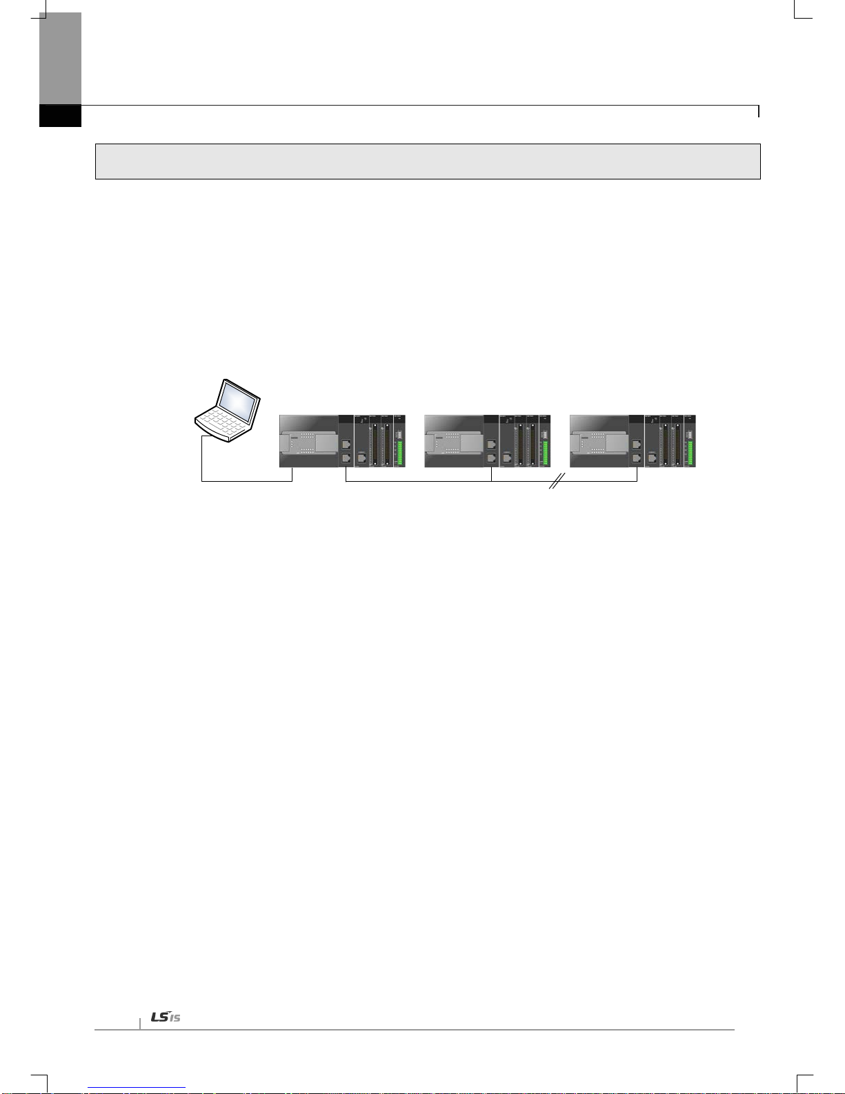
Chapter 7 Diagnosis Function
7-12
7.4 Remote Communication control
7.4.1 Introduction
This function is used f or pro gram m ing, do wnlo adin g of user progr am , pro gram de bugg ing, m oni tor ing, e tc in network
system where PLCs are connected with each other via Ethernet by remote control without moving the physical
connection status of XG5000. It is especially convenient for easy access to each device from a place without
repositioning when network-connected devices are se parated far. XG5000 remote c onnection service is av ailable
under the following Logical Path to attain its purpose.
PLC#1
IP: 192.168.91.188
PLC#2
IP: 192.168.91.189
PLC#N
IP: 192.168.91.190
XG5000
Remote connection
(Logical connection via Eternet communication module)
Local connection
(RS-232C or USB )
[Figure 7.4.1] Ethernet/IP network
A network is suppose d where RS-232C cable is c onnected bet ween PC in which XG5000 is installed and PLC #1
station, and PLC #1, PLC #2 and PLC #n are connected with each other via Ethernet in XG5000 of [Figure 7.4.1]. To
access the contents of PLC #1 station in the figure above, Local connection is needed in XG5000’s on-line menu. After
finishing acc essing the c ontents of PLC #1, disconnect the Local co nnection with ‘Disconnect’ menu. To access the
PLC #n station, select PLC #n by setting the IP address of PLC #n and Base and Slot No. where XBL-EIPT module is
installed in th e PLC #1 station i n the remote co nnection dialog box an d connect. The n logical connection bet ween
XG5000 and PLC #n will be established via RS-232C and Ethernet. This status is identical to the status that RS-232C
cable is connected bet ween PC and PLC #n station and it is availabl e to execute all functions of programming,
downloading, debugging and monitoring as in PLC #1.
Also, if Ether net/IP module (LAN Card) is insta lled on PC wher e XG5000 is instal led and connected to th e identic al
network to PLC, remote stage 1 connection with PLC is available via Ethernet without local connection via RS-232C.
With the rem ote connect ion service of XG5000, easy access to PLC is possible even if t he PLC is located at a far
place. And re-programming without repositioning the PLC is possible when PLC is located at a place hard to reach.

Chapter 7 Diagnosis Function
7
-13
7.4.2 Setting and Connection
All PLCs con nected via XGT network are available to connect with each other by remote connec tion service. XG5000 remote
connection is composed of stage 1 and stage 2 connections as described below.
The followings explains remote 1 and remote 2 connections.
Logical connection via Ethernet module
(remote1)
Network#1
Network#2
Logical connection via Ethernet module
(remote2)
Rem ot e 2
Rem ot e 1
PLC#1
IP: 192.168.91.188
PLC#2
IP: 192.168.91.189
PLC#N
IP: 192.168.91.190
XG5000
Local connection
(RS-232C or USB )
PLC#A
IP: 192.168.91.191
PLC#B
IP: 192.168.91.192
[Figure 7.4.2] Remote connection
[Figure 7.4. 2] show s an example of network system composed of two networks.
(1) Remote stage 1 connection (If RS-232C cable used)
For remote stage 1 connection, XG5000 shall be in off-line state.
Click [Online] -> [Connecti on setti ngs]
[Figure 7.4.3] XG5000 remote connection option to select
(a) Connectio n type
It designat es the connecting method for local connection . Local connection is applied with RS-232C used as in [Fig.
7.4.3]. Sel ect the port used in PC for a communication port. The case that Ethernet is used for local connection will be
described in the next section. Refer to user’s manual of each communication module for the case with other
connection ty pes.
(b) Connecti on depth
Decide a PLC
connection stage of local, remote stage 1 or 2. Select remote stage 1 here.
 Loading...