


Right choice for ultimate yield
LSIS strives to maximize customers' profit in gratitude of choosing us for your partner.
Programmable Logic C ontroller
XGB Cnet I/F
User’s Manual
Read this manual carefully before
installing,
wiring, operating, servicing
or inspecting this equipment.
Keep this manual within easy reach
for quick reference.
XGT Series
http://www.lsis.com
Main Unit
Built
-in Cnet
S TYPE
E TYPE
S TYPE
SU TYPE
H TYPE
Cnet I/F
module
XBL-C41A
XBL
-C21A
XBM
XBC
/XEC
XBC
/XEC
XBC
/XEC
XBC
/XEC

Safety Instruction
Before using the product …
For your safety and effective operation, please read the safety instructions
thoroughly before using the product.
► Safety Instructions should always be observed in order to prevent accident
or risk by using the product properly and safely.
► Precautious measures can be categorized as “Warning” and “Caution”, and
each of the meanings is as follows.
This symbol indicates the possibility of serious injury
or death if some applicable instruction is violated
This symbol indicates the possibility of severe or
slight injury, and damages in products if some
applicable instruction is violated
Moreover, even classified events under its caution category may develop into
serious accidents depending on situations. Therefore we strongly advise users
to observe all precautions in a proper way just like warnings.
► The marks displayed on the product and in the user’s manual have the
following meanings.
Be careful! Danger may be expected.
Be careful! Electric shock may occur.
After reading this user’s manual, it should be stored in a place that is visible
to product users.
Warning
Caution

Safety Instruction
Safety Instructions when designing
Please, install protection circuit on the exterior of PLC to protect
the whole control system from any error in external power or PLC
module. Any abnormal output or operation may cause serious problem
in safety of the whole system.
- Install applicable protection unit on the exterior of PLC to protect
the system from physical damage such as emergent stop switch,
protection circuit, the upper/lowest limit switch, forward/reverse
operation interlock circuit, etc.
- If any system error (watch-dog timer error, module installation error,
etc.) is detected during CPU operation in PLC, the whole output is
designed to be turned off and stopped for system safety. However,
in case CPU error if caused on output device itself such as relay or
TR can not be detected, the output may be kept on, which may
cause serious problems. Thus, you are recommended to install an
addition circuit to monitor the output status.
Never connect the overload than rated to the output module nor
allow the output circuit to have a short circuit, which may cause a
fire.
Never let the external power of the output circuit be designed to
be On earlier than PLC power, which may cause abnormal output or
operation.
In case of data exchange between computer or other external
equipment and PLC through communication or any operation of
PLC (e.g. operation mode change), please install interlock in the
sequence program to protect the system from any error. If not, it
may cause abnormal output or operation.
Warning

Safety Instruction
Safety Instructions when designing
Safety Instructions when designing
I/O signal or communication line shall be wired at least 100mm
away from a high-voltage cable or power line. If not, it may cause
abnormal output or operation.
Caution
Use PLC only in the environment specified in PLC manual or
general standard of data sheet. If not, electric shock, fire, abnormal
operation of the product or flames may be caused.
Before installing the module, be sure PLC power is off. If not,
electric shock or damage on the product may be caused.
Be sure that each module of PLC is correctly secured. If the
product is installed loosely or incorrectly, abnormal operation, error or
dropping may be caused.
Be sure that I/O or extension connecter is correctly secured. If
not, electric shock, fire or abnormal operation may be caused.
If lots of vibration is expected in the installation environment,
don’t let PLC directly vibrated. Electric shock, fire or abnormal
operation may be caused.
Don’t let any metallic foreign materials inside the product, which
may cause electric shock, fire or abnormal operation..
Caution

Safety Instruction
Safety Instructions when wiring
Prior to wiring, be sure that power of PLC and external power is
turned off. If not, electric shock or damage on the product may be
caused.
Before PLC system is powered on, be sure that all the covers of
the terminal are securely closed. If not, electric shock may be caused
Warning
Let the wiring installed correctly after checking the voltage rated
of each product and the arrangement of terminals. If not, fire,
electric shock or abnormal operation may be caused.
Secure the screws of terminals tight ly with specified torque when
wiring. If the screws of terminals get loose, short circuit, fire or abnormal
operation may be caused.
*
Surely use the ground wire of Class 3 for FG terminals, which is
exclusively used for PLC. If the terminals not grounded correctly,
abnormal operation may be caused.
Don’t let any foreign materials such as wiring waste inside the
module while wiring, which may cause fire, damage on the product
or abnormal operation.
Caution

Safety Instruction
Safety Instructions for test-operation or repair
Safety Instructions for waste disposal
Don’t touch the terminal when powered. Electric shock or abnormal
operation may occur.
Prior to cleaning or tightening the terminal screws, let all the
external power off including PLC power. If not, electric shock or
abnormal operation may occur.
Don’t let the battery recharged, disassembled, heated, short or
soldered. Heat, explosion or ignition may cause injuries or fire.
Warning
Don’t remove PCB from the module case nor remodel the module.
Fire, electric shock or abnormal operation may occur.
Prior to installing or disassembling the module, let all the external
power off including PLC power. If not, electric shock or abnormal
operation may occur.
Keep any wireless installations or cell phone at least 30cm away
from PLC. If not, abnormal operation may be caused.
Caution
Product or battery waste shall be processed as industrial waste.
The waste may discharge toxic materials or explode itself.
Caution

Revision History
V
ersion Date Remark Page
V 1.0 2006.6
1. First Edition -
V 1.1 2007.7 1. Position and Special function contents separated
(1) Position function contents separated
(position part published)
(2) PID control and Ch. 12 Analog IO module contents
separated
2. Contents added
(1) Naming standard added
(2) Caution when selecting IO module added
(3) Installation and wiring contents added
3. Content modified
(1) Safety instruction modified
(2) System Configuration modified
(3) High speed counter function modified
(4) External dimension modified
-
-
2-3 ~ 2-6
7-1 ~ 7-6
10-1 ~ 10-18
1 ~ 6
2-7 ~ 2-10
8-6 ~ 8-8
App. 2-1 ~ 2-4
V 1.2 2008.3 1. XGB compact type ‘H’ type added
2. Built-in communication content separated
(1) Ch.9 built-in communication function separated
(Cnet I/F user manual)
-
Ch. 9
V 1.3 2010.3 1. XEC compact type added -
V 1.4 2010.5
1. Standard format applied
2. Modbus protocol added
3. Contents changed
(1) Ch. 5 Communication function
→ Ch. 6 Server function and P2P service
(2) Ch. 6 Remote connection → Ch. 5 Remote connection
-
Ch. 8
Ch. 5, Ch. 6
V 1.5 2013.4
1. Main unit added
(1) XBC/XEC ‘E’ type
(2) XBC/XEC ‘S/SU’ type
(3) XBC/XEC ‘H’ type
2. Contents added
(1) ‘NOTE’ for XGT Dedicated Protocol
2-4 ~ 2-7
7-6
V 1.6 2014.3
1. LS Bus Protocol added
2. Ch.8 ~ Ch.12 → Ch.9 ~ Ch.13
3. Applicable device revised
Ch.8
Ch.9 ~ Ch.13
Ch.7
※ The number of User’s manual is indicated the right side of the back cover.
Copyrights ⓒ 2006 LSIS Co., Ltd All Rights Reserved.

About User’s Manual
About User’s Manual
Congratulations on purchasing PLC of LSIS Co.,Ltd.
Before use, make sure to carefully read and understand the User’s Manual about the functions,
performances, installation and programming of the product you purchased in order for correct use and
importantly, let the end user and maintenance administrator to be provided with the User’s Manual.
The Use’s Manual describes the product. If necessary, you may refer to the following description and order
accordingly. In addition, you may connect our website(http://eng.lsis.biz/
) and download the information as a
PDF file.
Relevant User’s Manual
Title Description
No. of User
Manual
XG5000 User’s
Manual
It describes how to use XG5000 software especially about
online functions such as programming, printing, monitoring
and debugging by using XGT series products.
10310000512
XGK/XGB Series
Instruction &
Programming
It describes how to use the instructions for programming
using XGK/XGB series.
10310000510
XGB Hardware
User’s Manual
It describes how to use the specification of power/input
/output/expansion modules, system configuration and built-in
High-speed counter for XGB basic unit.
10310000926
XGB Analog
User’s Manual
It describes how to use the specification of analog
input/analog output/temperature input module, system
configuration and built-in PID control for XGB basic unit.
10310000920
XGB Position
User’s Manual
It describes how to use built-in positioning function for XGB
unit.
10310000927
XGB Cnet I/F
User’s Manual
It describes how to use built-in communication function for
XGB basic unit and external Cnet I/F module.
10310000816
XGB Fast Ethernet I/F
User’s Manual
It describes how to use XGB FEnet I/F module.
10310000873

◎
Contents
◎
Chapter 1 General---------------------------------------------------------------------------------------------- 1-1 ~ 1-2
1.1 General --------------------------------------------------------------------- 1-1
1.2 Characteristic--------------------------------------------------------------- 1-2
Chapter 2 Specification -------------------------------------------------------------------------------------- 2-1 ~ 2-9
2.1 General Specification ------------------------------------------------------------------------- 2-1
2.2 Performance Specification -------------------------------------------------------------------- 2-3
2.3 Name and Function of each part ---------------------------------------------------------- 2-5
Chapter 3 System Configuration--------------------------------------------------------------------------3-1~ 3-10
3.1 XGB System Configuration ------------------------------------------------------------- 3-1
3.1.1 “H” type system configuration --------------------------------------------------- 3-1
3.1.2 “S” type System Configuration ---------------------------------------------------- 3-2
3.2 Available System Configuration ------------------------------------------------------------ 3-3
3.2.1 1:1 Connection between PC (HMI) (No modem) -------------------------------------- 3-3
3.2.2 1:1 Dedicated modem c onnection with PC (HMI) ---------------------------------------- 3-6
3.2.3 Modem conn ect ion w i th PC an d c om munication between Cnet I/F modules -------- 3-7
3.2.4 Dedicated communication with PC (HMI) and different type RS-422 communication ---- 3-8
3.2.5 Optical modem communication for moving material communication ------------------- 3-9
3.2.6 Wireless modem communication for communication between revolution bodies --------------- 3-10
Chapter 4 Basic Setting -------------------------------------------------------------------------------------- 4-1 ~ 4-8
4.1 Setting Sequence of Product --------------------------------------------------------- 4-1
4.2 PLC Type Setting an d Ho w t o Register Communication Module --------------------------------- 4-2
4.2.1 Making new project ---------------------------------------------------- 4-2
4.2.2 In case of off line, method on Cnet I/F module registration -------------------- 4-2
4.2.3 How to register Cnet I/F module in case of online ---------------------- 4-3
4.3 How to Set Basic Parameter ------------------------------------------------------- 4-5
4.3.1 Setting item ------------------------------------------------------------- 4-6
4.2.2 Setting method ------------------------------------------------------------ 4-7

Chapter 5 Remote Connection -------------------------------------------------------------------------- 5-1 ~ 5-12
5.1 Server Modbus Service ----------------------------------------------------------------- 5-1
5.1.1 General ---------------------------------------------------------------------------- 5-1
5.1.2 XG5000 remote connection -------------------------------------------------------- 5-2
5.1.3 Remote connection between Cnet I/F modules-------------------------------- 5-8
Chapter 6 Server function and P2P service---------------------------------------------------------- 6-1 ~ 6-12
6.1 Server Modbus Service----------------------------------------------------------------------------- 6-1
6.1.1 General ------------------------------------------------------------------------------------ 6-1
6.1.2 XGT dedicated server------------------------------------------------------------------- 6-2
6.1.3 Modbus server ----------------------------------------------------------------------- 6-2
6.2 P2P Service ---------------------------------------------------------------------------- 6-4
6.2.1 General ------------------------------------------------------------------------------------------------- 6-4
6.2.2 P2P param eter configuration -------------------------------------------------------------------- 6-5
6.2.3 Channel inform ation -------------------------------------------------------------------------------- 6-5
6.2.4 Block information -------------------------------------------------------------------------------- 6-7
6.2.5 User defined frame information ----------------------------------------------------------------- 6-11
6.2.6 P 2P service operatio n ---------------------------------------------------------------------------- 6-21
Chapter 7 XGT Dedicated Protocol -------------------------------------------------------------------- 7-1 ~ 7-19
7.1 XGT Dedicated Protocol ---------------------------------------------------------- 7-1
7.1.1 General ---------------------------------------------------------------------------- 7-1
7.1.2 Frame structure ----------------------------------------------------------------- 7-2
7.1.3 List of commands ----------------------------------------------------------------- 7-3
7.1.4 Data type ----------------------------------------------------------------------- 7-4
7.1.5 Detail of instruction ---------------------------------------------------------- 7-6
Chapter 8 LS Bus Protocol ------------------------------------------------------------------------------- 8-1 ~ 8-6
8.1 LS Bus Protocol -------------------------------------------------------------------------------- 8-1
8.1.1 Frame structure ---------------------------------------------------------------------------- 8-1
8.1.2 List of commands ------------------------------------------------------------------------ 8-2
8.2 Detail of instruction -------------------------------------------------------------------------------- 8-1
8.2.1 Continuous wr iting to inverter dev ice (W) ----------------------------------------------------- 8-3
8.2.2 Inverter continuous r eading (R) ----------------------------------------------------------------- 8-5

Chapter 9 Modbus Communication -------------------------------------------------------------------- 9-1 ~ 9-15
9.1 General ------------------------------------------------------------------------------------------------ 9-1
9.2 Modbus Protocol -------------------------------------------------------------------------------------- 9-1
9.2.1 Kind of modbus protocol------------------------------------------------------------------- 9-1
9.2.2 Structure of modbus protocol------------------------------------------------------------------ 9-1
9.3 Structure of Frame --------------------------------------------------------------------------------------- 9-3
9.3.1 Structure of Frame in the ASCII mode -------------------------------------------------------- 9-3
9.3.2 Frame structure in the RTU mode ----------------------------------------------------- 9-3
9.3.3 Data and expression of address -------------------------------------------------------- 9-4
9.4 Modbus Protocol------------------------------------------------------------------------------------ 9-6
9.4.1 Reading data of bit t ype a t t he bit o utput (01) ------------------------------------------------ 9-6
9.4.2 Read Input Status (02) ----------------------------------------------------------------------- 9-7
9.4.3 Read Ho lding Regist ers (03)---------------------------------------------------------------------- 9-8
9.4.4 Read Input R egisters ( 04) ------------------------------------------------------------------------- 9-9
9.4.5 Force Single Coil (05) ----------------------------------------------------------------------------- 9-10
9.4.6 Preset Single R egiste r (06) ----------------------------------------------------------------------- 9-11
9.4.7 Force Multip le Coils (0F) ------------------------------------------------------------------------- 9-12
9.4.8 Preset Multi ple Regis ters (10) ------------------------------------------------------------------ 9-14
Chapter 10 Example Program------------------------------------------------------------------------- 10-1 ~ 10-25
10.1 Setting of Cnet I/F module in the XG-PD ------------------------------------------ 10-1
10.1.1 In case of acting as server ------------------------------------------------- 10-1
10.1.2 In case of acting as P2P service (client) -------------------------------- 10-3
10.2 Dedicated Communication Example ------------------------------------------------------- 10-6
10.2.1 Settings of XGT server ---------------------------------------------------- 10-7
10.2.2 Settings of XGT client ---------------------------------------------------- 10-8
10.2.3 Checking the operation ------------------------------------------------------ 10-11
10.3 Modbus Communication Example ----------------------------------------------------- 10-12
10.3.1 Modbus RT U ser ver setting ------------------------------------------------------------------ 10-13
10.3.2 Setting of Modbus RTU client ----------------------------------------------------------- 10-15
10.4 User defined Comm unicat ion Exam ple ------------------------------------------------------------- 10-20
10.4.1 User define d c om m unication example syst em configuration ------------------------ 10-20
10.4.2 User definition com munic ation fram e structure ----------------------------------------- 10-21
10.4.3 User def initi on com m unication paramet er setti ng -------------------------------------- 10-22

Chapter 11 Diagnosis ------------------------------------------------------------------------------------- 11-1 ~ 11-8
11.1 Diagnosis F unction of XG-PD -------------------------------------------------------------------------- 11-1
11.1.1 Check ing status of main unit ------------------------------------------------------------------- 11-2
11.1.2 Communication m odule information --------------------------------------------------------- 11-2
11.1.3 Frame monitor ------------------------------------------------------------------------------------- 11-3
11.1.4 Status by service ---------------------------------------------------------------------------------- 11-4
11.2 Trouble Shooting by Error ------------------------------------------------------------------------------ 11-6
11.2.1 Trouble shooing when P2P parameter setting error occurs in case of XG5000
connection -------------------------------------------------------------------------------------------11-6
11.2.2 Trouble shooting when communication is not done after P2P client setting - 11-6
11.2.3 Trouble shooting when response frame is missed in case of acting as client and
using RS-485 ----------------------------------------------------------------------------------------------- 11-7
11.2.4 Two response fram e are deal t with as unk no wn when ex ecuting f ram e m onitor --11-7
11.2.5 Una ble to anal yze TRX fr ame ----------------------------------------------------------------- 11-7
11.2.6 Unab le to know which one is reason of error, client or server ------------------------ 11-7
11.2.7 Communication is not normal or communication is not executed repeatedly
-------------------------------------------------------------------------------------------------11-8
Chapter 12 Installation and Wiring ------------------------------------------------------------------ 12-1 ~ 12-24
12.1 Safety Instruction ------------------------------------------------------------------------------------------- 12-1
12.1.1 Fail safe circuit -------------------------------------------------------------------------- 12-3
12.1.2 PLC heat calculation -------------------------------------------------------------- 12-6
12.2 Attachment/Detachment of Modules -------------------------------------------------------- 12-8
12.2.1 Attachment/Detachment of modules ------------------------------------------------ 12-8
12.2.2 Caution in handling -------------------------------------------------------------------- 12-12
12.3 Wire -------------------------------------------------------------------------------------------------- 12-13
12.3.1 Power wiring --------------------------------------------------------------------------- 12-13
12.3.2 I/O Device wiring ----------------------------------------------------------------- 12-16
12.4 Channel Operation during Normal Run -------------------------------------------------- 12-17
12.5 Communication Interface Connection Method ------------------------------------------------ 12-18
12.5.1 RS-232C Interface (XBL-C21A) ---------------------------------------------------- 12-18
12.5.2 RS-422/485 interface (Built-in communication) ------------------------------- 12-20
12.5.3 RS-422 interface (XBL-C41A) ---------------------------------------------------- 12-21
12.6 Cable Specifications --------------------------------------------------------------------------- 12-23
12.6.1 Electrical characteristic ------------------------------------------------------------- 12-23
12.5.2 External characteristic ------------------------------------------------------------ 12-23
12.7 Terminal Resistance -------------------------------------------------------------------------- 12-24

Chapter 13 Maintenance --------------------------------------------------------------------------------- 13-1 ~ 13-2
13.1 Maintenance and Inspection -------------------------------------------------------------- 13-1
13.2 Daily Inspection ------------------------------------------------------------------------------ 13-1
13.3 Periodic Inspection --------------------------------------------------------------------------------- 13-2
Appendix ------------------------------------------------------------------------------------------------------- A-1 ~ A-17
Appendix 1 Definition of Terms ------------------------------------------------------------------ A-1
Appendix 1.1 General Terms --------------------------------------------------------------------------- A-1
Appendix 1.2 Serial Communication Terms ----------------------------------------------- A-2
Appendix 2 Communication Relay List (L) -------------------------------------------------------------- A-8
Appendix 2.1 Communication Relay (L) List ---------------------------------------------- A-8
Appendix 2.2 Network Register (N) List -------------------------------------------------- A-11
Appendix 3 Communication Error Code ------------------------------------------------------------- A-12
Appendix 3.1 XGT Server Error Code -------------------------------------------------- A-12
Appendix 3.2 Modbus Server Error Code --------------------------------------------- A-13
Appendix 3.3 P2P Client Error Code ------------------------------------------------------------- A-13
Appendix 4 Dimension (Un it: mm) -------------------------------------------------------------------------- A-14

Chapter 1 General
1-1
Chapter 1 General
1.1 General
This user manual provides the information of Cnet I/F among XGB PLC system network about
specification/performance and how to operate.
Configuration of user manual is as follows.
Chapter Item Content
1 General Describes configuration of manual, product characteristic and term
2 Specification
Indicates general specification and performance specification of each m odule
used XGB PLC.
3 System configuration Describes basic communication parameter setting.
4 Basic setting Describes basic communication setting
5
Communication
function
Describes server for data communication between PLC and P2P parameter
setting.
6 Remote connection
Describes CPU connection method by communication chann el through
XG5000, XG-PD.
7
XGT dedicated
protocol
Describes XGT dedicated communication frame structure.
8 Example program Describes example program for communication test.
9 Diagnosis function Describes about self diagnosis by XG-PD.
10
Installation and
wiring
Describes installation and wiring.
11 Maintenance Describes maintenance.
App.1 Term Describes term used in this manual
App.2 Flag list Describes parameter setting N area, flag L related with Cnet I/F.
App.3
Communication error
code
Describes XGT server, modbus server, P2P error code.
App.4 Dimension Describes dimension of communication module.

Chapter 1 General
1-2
1.2 Characteristic
(1) By using XG-PD operated in window environment, since the user can write communication speed,
communication mode (protocol), connection with external device is easy.
(2) RS-232C 1 port, RS-485 1 port as main unit built-in Cnet is supported. Two type of Cnet I/F
module as extension, RS-232C 1 port (XBL-C21A), RS-422(485) 1port (XBL-C41A) is provided.
(3) It operates independently according to channel, since protocol data written by user is managed by
main unit, in case communication module is changed other than communication module,
additional setting/download is not necessary.
(4) Device read/write by using XGT dedicated/modbus/user defined protocol is available.
(5) It provides communication function in which multidrop, up to 32 connection is available in case of
using RS-422/485.
(6) Setting of diverse communication speed is available.
(1200,2400,4800,9600,19200,38400,57600,115200bps)
(7) 1:1 and 1:N communication are available.
(8) With abundant self-diagnosis, trouble diagnosis is simple.
(9) It supports dedicated server/client, modbus server/client, user defined communication function.
(10) In case of XBL-C21A module, modem communication is provided, by which controlling remote
PLC is available.

Chapter 2 specification
2-1
Chapter 2 Specification
2.1 General Specification
General specification of XGB PLC is as follows.
No. Item Specification Related specifications
1
Operating
temp.
0℃∼+55℃
2 Storage temp. -25℃∼+70℃
3
Operating
humidity
5∼95%RH, no dew allowed
4
Storage
humidity
5∼95%RH, no dew allowed
5
Vibration
proof
For discontinuous vibration
Frequency Acceleration Amplitude Number
IEC 61131-2
10≤f< 57㎐ - 0.075mm
Each 10 times
in X,Y,Z
directions
57≤f≤150㎐ 9.8㎨ -
For continuous vibration
Frequency Acceleration Amplitude
10≤f< 57㎐ - 0.035mm
57≤f≤150㎐ 4.9㎨(0.5G) -
6 Impact proof
* Max. impact acceleration: 147㎨(15G)
* Authorized time: 11㎳
* Pulse wave : Sign half-wave pulse
(
Each 3 times in X,Y,Zdirections
)
IEC 61131-2
7 Noise proof
Square wave impulse noise AC:±1,500V, DC: 500 V
Test spec of LS
Industrial Systems
Static electric discharging
Voltage: 4 kV
(contact discharging),
8 kV (air discharging)
IEC 61131-2,
IEC 61000-4-2
Radiation electromagnetic 80 ~ 1,000MHz, 10 V/m
IEC 61131-2,
IEC 61000-4-3
Fast
Transient
/burst
noise
Class
Power
module
Digital/
Analog I/O
communication interface
IEC 61131-2,
IEC 61000-4-4
Voltage 2kV 1kV
8
Ambient
conditions
No corrosive gas or dust
9
Operating
height
2000m or less
10 Pollution level 2 or less
11 Cooling type Natural air cooling

Chapter 2 specification
2-2
[1] IEC (International Electro technical Commission):
An international nongovernmental organization which promotes internationally cooperated
standardization in electric/electronic fields, publishes international standards and manages applicable
estimation system related with.
[2] Pollution level: An index indicating pollution level of the operating environment which decides
insulation performance of the devices. For instance, Pollution level 2 indicates the state generally that
only non-conductive pollution occurs. However, this state contains temporary conduction due to dew
produced.
Notes

Chapter 2 specification
2-3
2.2 Performance Specification
(1) Built-in Cnet performance specification
Performance specification of XGB built-in Cnet is as follows.
Item
Specification
Channel 1
Channel 2
Serial communication
method
RS-232C RS-485
Modem connection
function
- -
Operation
mode
(Operation
define by
channel)
P2P
Act as communication client
- XGT dedicated protocol client
- Modbus ASCII/RTU client
- User defined communication
- LS Bus Client
Notes 1)
Server
- XGT dedicated protocol server
- Modbus ASCII/RTU server
Data
type
Data bit
7 or 8
Stop bit
1 or 2
Parity
Even/Odd/None
Synchronization type
Asynchronous type
Transmission speed
(bps)
1200/2400/4800/9600/19200/38400/57600/115200 bps available
Station No. setting
Setting range: 0~255
Max. station No. available: 32 stations
Transmission
distance
Max. 15m Max. 500m
Diagnosis function Check available by XG-PD diagnosis service
Notes
Notes 1) < LS Bus Client applicable version>
Series XBM XBCH XBCSU XBCS XBCE XG5000
Version V3.40 or above V2.30 or above V1.40 or above V1.30 or above V1.20 or above V3.69 or above
Series XBCEX XBCEB XECH XECSU XECE -
Version V1.01 or above V1.01 or above V1.70 or above V1.30 or above V1.10 or above
-

Chapter 2 specification
2-4
(2) Extension Cnet performance specification
XGB extension Cnet communication module performance specification is as follows
Item
Specification
XBL-C21A
XBL-C41A
Serial communication
channel
RS-232C 1 channel RS-422(485) 1 channel
Modem connection
function
External modem connection available -
Operation
mode
(Operation
definition
by port)
P2P
Operates as communication client
- XGT dedicated protocol client
- Modbus ASCII/RTU client
- User defined communication
- LS Bus Client
Server
- XGT dedicated protocol server
- Modbus ASCII/RTU server
Data
type
Data bit
7 or 8
Stop bit
1 or 2
Parity
Even/Odd/None
Synchronization type
Asynchronous type
Transmission speed
(bps)
1200/2400/4800/9600/19200/38400/57600/115200 bps available
Station No. setting
Setting range: 0~255
Max. station No. available: 32 stations
Transmission
distance
RS-232C: 15m
(Extension available in c ase of using
modem)
RS-422/485: max 500m
Diagnosis function Check available by LED and XG-PD diagnosis service
Consumption current
120mA
120mA
Weight
56g
56g

Chapter 2 specification
2-5
2.3 Name and Function of each part
XBM “S” Type
No. Name Purpose
①
Input indication LED Input indication LED
②
PADT connection
connector
PADT connection connector
③
Input connector and
terminal block
Input connector and terminal block
④
Output connector and
terminal block
Output connector and terminal block
⑤
Key switch
RUN / STOP key switch
- In case key switch is STOP, remote mode change available
⑥ Output indication LED Output indication LED
⑦
Status indication LED
Indicates operation status of CPU module
- PWR(Red): Power status indication
- RUN(Green): RUN status indication
STOP mode: Off / RUN mode : On
- Error(Red): Flicker in case error occurs
⑧
8-1
Built-in RS-485
Connection
connector
Built-in RS-485 connection connector
- “+”, “-“ terminal connection connector ofRS-485 communication
8-2
Built-in RS-232C
connection
connector
Built-in RS-232C connection connector
-“TD”, “RD”, “SG” terminal connection connector of RS-232C
communication
8-3 Power connector DC24V power connector
①
②
④
⑤
⑥
③
⑦
③
⑧
8-1
8-2
④
①
②
⑤
⑥
⑦
XBM-DR16S
XBM-DN16/32S
8-3

Chapter 2 specification
2-6
XBC/XEC “E” type
No. Name Purpose
①
Input indication LED Input indication LED
②
PADT connection
connector
PADT connection RS-232C 1 channel connector
③
Input terminal block Input connector and terminal block
④
Output terminal block
Output connector and terminal block
⑤
Key switch RUN / STOP key switch
-In case key switch is STOP, remote mode change available
⑥
Output indication LED Output indication LED
⑦
Status indication LED Indicates basic unit’s operation status
- PWR(Red) : power status indication
- RUN(Green) : RUN status indication
- STOP mode : Off / RUN mode : On
- Error(Red): flicker in case error occurs
⑧
Built-in RS-232C/
RS-485 Connection
terminal block
Built-in RS-485 connection terminal block
- “+”,”-“ terminal connection terminal block of RS-485
communication
- “TD”,”RD”,”SG” terminal connection terminal block of
RS-232C communication
Power terminal AC100~240V power terminal block
Notes
Notes 1) XBC/XEC main units of "E” type are not able to use XGB expansion module.
XBC-DR10E
XBC-DN10E
XBC-DP10E
XBC-DR14E
XBC-DN14E
XBC-DP14E
XBC-DR20E
XBC-DN20E
XBC-DP20E
XBC-DR30E
XEC-DN10E
XEC-DN14E
XEC-DN20E
XEC-DN30E
XEC-DP10E
XEC-DP14E
XEC-DP20E
XEC-DP30E
XEC-DR10E

Chapter 2 specification
2-7
XBC/XEC “S/SU” type
No. Name Purpose
①
Input indication LED Input indication LED
②
PADT connection
connector
PADT connection USB(USB 1.1 supported) 1 channel,
RS-232C 1 channel connector
Notes 1)
③
Input terminal block Input connector and terminal block
④
Output terminal block
Output connector and terminal block
⑤
Key switch RUN / STOP key switch
-In case key switch is STOP, remote mode change available
⑥
Output indication LED Output indication LED
⑦
Status indication LED Indicates basic unit’s operation status
- PWR(Red) : power status indication
- RUN(Green) : RUN status indication
- STOP mode : Off / RUN mode : On
- Error(Red): flicker in case error occurs
⑧
Built-in RS-232C/
RS-485 Connection
terminal block
Built-in RS-485 connection terminal block
- “+”,”-“ terminal connection terminal block of RS-485
communication
- “TD”,”RD”,”SG” terminal connection terminal block of
RS-232C communication
Power terminal AC100~240V power terminal block
Notes
Notes 1) The S-type of XBC/XBC doesn’t provide a usb port.
XBC-DN20S(U)
XBC-DR20SU
XBC-DN30S(U)
XBC-DR30SU
XBC-DN40SU
XBC-DR40SU
XBC-DN60SU
XEC-DN20SU
XEC-DN30SU
XEC-DN40SU
XEC-DN60SU
XEC-DR20SU
XEC-DR30SU

Chapter 2 specification
2-8
XBC/XEC “H” type
No. Name Purpose
①
Input indication LED Input indication LED
②
PADT connection
connector
PADT connection USB(USB 1.1 supported) 1 channel,
RS-232C 1 channel connector
③
Input terminal block Input connector and terminal block
④
Output terminal block
Output connector and terminal block
⑤
Key switch RUN / STOP key switch
-In case key switch is STOP, remote mode change available
⑥
Output indication LED Output indication LED
⑦
Status indication LED Indicates basic unit’s operation status
- PWR(Red) : power status indication
- RUN(Green) : RUN status indication
- STOP mode : Off / RUN mode : On
- Error(Red): flicker in case error occurs
⑧
Built-in RS-232C/
RS-485 Connection
terminal block
Built-in RS-485 connection terminal block
- “+”,”-“ terminal connection terminal block of RS-485
communication
- “TD”,”RD”,”SG” terminal connection terminal block of
RS-232C communication
Power terminal AC100~240V power terminal block
XEC-DN32H
XEC-DN64H
XEC-DP32H
XEC-DP64H
XEC-DR32H
XEC-DR64H
XBC-DR32H
XBC-DN32H
XBC-DR64H
XBC-DN64H

Chapter 2 specification
2-9
Extension Cnet module
No. Name Purpose
①
LED indication Operation status indication
②
RS-422/RS-485
connector
Connector for connection with external device
③
RS-232C connector Connector for connection with external device
LED name LED indication content LED status LED status content
RUN Operation status indication
On Normal operation
Off Abnormal operation
I/F
Interface with main unit status
indication
Flicker Normal operation
Off Abnormal operation
TX Indication during frame transmission
Flicker Transmitting frame
Off Frame transmission completion
RX Indication during frame receiving
Flicker Receiving frame
Off Frame reception completion
ERR Frame error indication
On Frame error
Off Normal frame
[Table 2.3.1] LED indication content
①①
②③
XBL-C41A
XBL-C21A

Chapter 3 System Configuration
3-1
Chapter 3 System Configuration
XGB PLC is having diverse product suitable for main syst em, computer lin k and network system conf iguration
This chapter describes configurati on method and ch aracteristi c.
3.1 XGB System Configuration
System configuration of XGB PLC is as follows. Extension I/O module, in case of spe cial module, in “S” type, up
to 7 step connection and in “H” type, up to 10 step connection is available. In communication module, up to 2 step
extensions is available.
3.1.1 “H” type system configuration
Item content
I/O configuration point XB(E)C-DxxxH: 32 ~ 384 points
Extension module
connection available no.
Digital I/O module Max. 10
Analog module Max. 10
Communication
module
Max. 2
Product list
Main unit “H” type
XBC-DR32/64H XBC-DN32/64H
XEC-DR32/64H XEC-DN32/64H
Extension
module
Digital I/O module
XBE-DC08/16/32
XBE-TN08/16/32
XBE-TP08/16/32
XBE-RY08/16A
XBE-DR16A
Analog module
XBF-AD04A XBF-RD04A
XBF-DV04A XBF-RD01A
XBF-DC04A XBF-TC04S
Communication
module
XBL-C41A XBL-C21A
XBL-EMTA
Option
module
Memory module XBO-1024A
Main unit
I/O module
Special module
Communication
module

Chapter 3 System Configuration
3-2
3.1.2 “S” type System Configuration
Item Content
I/O configuration point XBM-DxxxS : 16 ~ 352 point
Extension module
connection available
no.
Digital I/O module Max. 7
Analog module Max. 7
Communication module Max. 2
Product
list
Main unit “S” type XBM-DR16S XBM-DN16/32S
Extension
module
Digital I/O module
XBE-DC08/16/32
XBE-TN08/16/32
XBE-TP08/16/32
XBE-RY08/16A
XBE-DR16A
Analog module
XBF-AD04A XBF-RD04A
XBF-DV04A XBF-RD01A
XBF-DC04A XBF-TC04S
Communication module
XBL-C41A XBL-C21A
XBL-EMTA
Option
module
Memory module XBO-1024A
Main unit I/O module Special module Communication module

Chapter 3 System Configuration
3-3
3.2 Available System Configuration
Communication system by using XGB built-in communication function and Cnet module is diverse. In this
chapter, it describes system configuration example.
.
3.2.1 1:1 Connection between PC (HMI) (No modem)
PC (HMI) and Cnet I/F module is connected by RS-232C or RS-422/485 channel, PC (HMI) and PLC is
connected by 1:1 without modem. In most case, PC (HMI) acts as client and Cnet I/F module acts as server which
respond request of PC (HMI). Since there is no modem, in case of using RS-232C channel, communication
distance is max 15m, in case of using RS-422 channel, communication distan ce is max 500m. Ope ration mod e of
Cnet I/F module is set according to PC (HMI)’s communication method. Wiring method and system connection is
applied in case of XGB “S” type built-in communication. In case of using XGB “H” type and external
communication module, refer to 10.5 communication interface connection method.
(1) In case of using 1:1 connection with normal PC
Wiring method
External form of
PC
PC
Connection number and signal
direction
XGB main unit
XGB external
form
Pin no. Pin no.
Signal
name
1
1 485-
2
(RXD)
2
485+
3(TXD) 3 SG
4 4 TX
5(GND) 5 RX
6
7
8
9
In case of using channel 2, connect 485+ and 485- of RS485 terminal.
[Figure 3.2.1] 1:1 communication with PC
XGB main unit built-in
communication
1
2
3
4
5
Female Type

Chapter 3 System Configuration
3-4
(2) In case of using 1:1 connection with monitoring device such as XGT Panel
Wiring method (RS-232C)
XP external form
XP
Connection number and
signal direction
XGB main unit
XGB external
form
Pin no. Pin no.
Signal
name
1 1 4852(RXD) 2 485+
3(TXD) 3 SG
4 4
TX
5(GND) 5
RX
6
7
8
9
Note) In case of PMU, short no.4 and no.6, short no.7 and no.8.
Wiring method (RS-485)
PMU
Connection no. and signal direction XGB main unit
485+ 485+
485-
485-
XP series (LSIS)
XGB main unit
RS-232C I/F
RS-485 I/F
Female Type
1
2
3
4
5
[Figure 3.2.2] 1:1 communication with HMI

Chapter 3 System Configuration
3-5
(3) In case of using 1:1 connection with XGB main unit
Wiring method
XGB external
form
XGB main unit
Connection no. and
signal direction
XGB main unit
Pin no.
Pin
no.
Signal name
1
1
485-
2 2
485+
3 3 SG
4 4 TX
5 5 RX
XGB main unit
XGB main unit
RS-232C I/F
RS-485 I/F
[Figure 3.2.3] 1:1 communication between PLCs

Chapter 3 System Configuration
3-6
3.2.2 1:1 Dedicated modem connection with PC (HMI)
It is 1:1 communication system connected through dedicated modem through RS-232C channel
with PC (HMI). Normally, PC (HMI) acts as client station, Cnet I/F module acts as server station
which respond request of PC (HMI). Since it uses modem, RS-232C channel should be set as
dedicated modem and long distance communication is available. Operation mode of this module
should be set according to communication method of PC (HMI).
[Figure 3.2.4] dedicated modem communication with PC
Modem
Modem
XBL-C21A
XBM-DN32S
XBL-C21A
XBM-DN32S

Chapter 3 System Configuration
3-7
3.3.3 Modem connection with PC and communication between Cnet I/F modules
PC and Cnet #1 station is connected by modem through RS-232C channel
Cnet #1 station ~ N station is communication between Cnet I/F module through RS-422 channel
Cnet #1 station ~ N station is Communication between Cnet I/F modules through RS-422
channel
PC acts as client station of Cnet #1 station
Up to max 32 station connection is available in case of Cnet I/F module (RS-422/485
communication)
It sets station 1 among Cnet I/F module as server station
Dedicate modem or dial-up modem available
[Figure 3.2.5] Dedicated modem communication with PC
Type
Module setting
XBL-C41A Station no.
PLC Cnet #1
P2P
1
XGT client
Cnet #2 ~ #N XGT server 2~N
[Table 3.2.1] module setting table per station
XGB PLC
Cnet # 1 station
XGB PLC
Cnet # N station
XGB PLC
Cnet # 2 station
RS-232C
Communication
RS-422 communication

Chapter 3 System Configuration
3-8
3.2.4 Dedicated communication with PC (HMI) and different type RS-422 communication
Null-modem communication by usin g PC (HMI) and RS-232C channel
PC (HMI) acts as client station, Cnet I/F module acts as server, at this time, module setting acts as
RS-232C XGT server
Cnet I/F module RS-422 channel acts as P2P mode.
It transmits indication data to display module of mosaic panel through RS-422 channel
Reading display transmissi on data from PC
[Figure 3.2.6] 7-Segment operating system for RS-422
Type
Module setting
XBL-C21A XBL-C41A Station no.
PLC Cnet #1 XGT server P2P 1
[Table 3.2.2] Module setting table per station
XGB PLC
Cnet # 1
HMI - PC
(GLOFA VIEW)
RS-232C communication
RS-422 communication

Chapter 3 System Configuration
3-9
3.2.5 Optical modem communication for moving material communication
Optical modem communication system for Cnet communication on material above moving
linearly
P2P communication or dedicated mode communication with monitoring device
RS-232C/RS-422 communication with optical modem
Communication between Cnet I/F mod ule is dedicated server/client communication
Optical modem connected with Cnet I/F module on m obile body can communicate with the
other optical modem only when positioned in communication available
Main application: Parking tower
[Figure 3.2.7] Optical modem communication system
XGB PLC
Cnet # 1
Monitoring
device
RS-232C
communication
RS-422
communication
XGB PLC
Cnet # 3
XGB PLC
Cnet # 2
XGB PLC
Cnet # 4
Optical
modem
Optical
modem
Optical
modem
Moving material
RS-232C communication
RS-232C communication
RS-232C communication
광
모
뎀

Chapter 3 System Configuration
3-10
3.2.6 Wireless modem communication for communication between revolution bodies
RS-232C communication with wireless modem
Communication between Cnet I/F module is dedicated/client communication
RS-232C channel of Cnet I/F module is dedicated modem mode
[Figure 3.2.8] wireless modem communication system
Type
Module setting
RS-232C RS-422 Station
XBL-C21A
Dedicated mode
Not used 2 station
User mode
[Table 3.2.3] setting content table between communication module
RS-232C communication
RS-232C
communication
XGB PLC
Cnet # 2
Wireless modem
Wireless modem

Chapter 4 Basic Setting
4-1
Chapter 4 Basic Setting
4.1 Setting Sequence of Product
It describes installation of product and sequence. Install system by be operated by the following
sequence.
Operation sequence
Equip Cnet I/F module to XGB system
(It is applied in case of using external Cnet I/F module)
Connect Cnet I/F module with device to communicate
by cable.
Cable wiring and connect terminal resistance.
After power on, check LED status of communication
module
Check whether interface of communication with CPU
is normal or not.
Set P2P parameter and basic setting at XG-PD.
Set parameter according to network configuration at
XG-PD, download parameter
Enable link at XG-PD.
Not enable link act as server.
Operation start
Note
1) In Cnet I/F module, hardware station setting is not necessary.
By using XG-PD, designate station and basic setting necessar y in Cnet communication.

Chapter 4 Basic Setting
4-2
4.2 PLC Type Setting and How to Register Communication Module
To use Cnet I/F function, communication parameter should be written by XGP-PD. To set system
about Cnet I/F module located in temporary position, register each module at XG-PD. Method on
register Cnet I/F module is as follows according to On/Off line status.
4.2.1 Making new project
First, after click File-New File and input project name, select XGB series as PLC series.
About CPU type, in case of “S” type, select “XGB-XBMS”, in case of “H” type, select “XBC-XBCH”.
In case of IEC type, select “XGB-XECH”
[Figure 4.2.1] New project making screen
4.2.2 In case of off line, method on Cnet I/F module registration
In the status PLC is not connected, in case the user set about communication module and write
parameter related with communication, in the “standard settings”, the user select slot location to
register Cnet I/F module and shows “Communication module settings” window. In this window, you
register Cnet I/F module about wanted slot position. If you double-click at the slot position, you can
set communication card. At this time, slot 0 is set as built-in Cnet. In case of using Cnet module other
than built-in Cnet, registration is necessary.

Chapter 4 Basic Setting
4-3
[Figure 4.2.2] Cnet module registration screen
4.2.3 How to register Cnet I/F module in case of online
If you register communication module at online status by using XG-PD, you should connect basic unit.
After [Online]-> [Online] after doing communication setting by using “Connection setting” -> Selecting
“Connection” and doing local connection (or remote 1/2 connection). In case of normal connection,
lower menu of “online” is activated, selecting [Online]-> “Read IO Information”, equipped
communication module is searched automatically.
[Figure 4.2.3] Cnet I/O information read screen

Chapter 4 Basic Setting
4-4
At this time, in case registered module is different with currently connected module or type of
communication module in the previous project, it shows whether it changes or not with the following
message.
[Figure 4.2.4] I/O information change message
If you execute Read IO Information, equipped communication module like the following is indicated
IO module information window.
[Figure 4.2.5] Communication module registration compete screen

Chapter 4 Basic Setting
4-5
4.3 How to Set Basic Parameter
Communication function used in Cnet I/F module is classified as followings.
1) Server mode service
Without other program at PLC, you can read or write information in PLC and data.
It can act as XGT server providing XGT dedicated protocol and Modbus server providing
RTU/ASCII protocol.
2) Client (P2P) service
Cnet I/F module acts as client in network.
In case designated event occurs, you can read or write memory of other station.
It can act as XGT client and Modbus client.
In case of sending/receiving user wanted frame and communicating with other device.
You can define P2P block with max. 32 per one channel acting independently.
3) Loader service
By using remote 1/2, you can monitor/download program about remote PLC.
To use Cnet I/F module, you should set transmission specification such as data type like transmission
speed and data/stop bit.
You should select transmission specification of system to be same with specification of system.
Written standard setting value is saved CPU module of PLC and this value keeps though power goes
off and this value is not changed before writing. Also though Cnet I/F module is changed and new
module is installed, the standard setting value saved at CPU module previously written is applied to
new module automatically. Standard communication setting parameter and P2P, all parameter is
applied if download is complete.

Chapter 4 Basic Setting
4-6
[Figure 4.3.1] Built-in communication standard setting screen
4.3.1 Setting item
When setting Cnet communication parameter, the fact the user should define is as follows [Table 4.3.1]
Item Setting content
Station no.
You can set from station 0 to station 255.
Communicati
on speed
1200, 2400, 4800, 9600, 19200, 38400, 57600,115200 bps available
Data bit
7 or 8 bit available
Parity bit
None, Even, Odd available
Stop bit
1 or 2 bit available
Communicati
on channel
It is fixed as follows according to Cnet type
1) Built-in communication → channel 1 : RS-232C , channel 2 : RS-485
2) XBL-C41A → channel 1 : not used, channel 2: RS-422/RS-485
3) XBL-C21A → channel 1 : not used, channel 2: RS-232C
Delay time
It sets interval of communication frame
Time out
It sets the time waiting respond after requesting data.(100㎳ unit 1~ 65535 available)
[Table 4.3.1] communication parameter setting item

Chapter 4 Basic Setting
4-7
*Parity bit
Cnet I/F module can define three parity bits. Meaning of each parity bit is as follows.
Parity bit type Meaning Reference
None Not using parity bit
Even If the number of 1 in one byte is even, parity bit becomes “0”.
Odd If the number of 1 in one byte is odd, parity bit becomes “1”.
[Table 4.3.2] Parity content table
Operation mode setting
▪ Sets operation mode
Driver type Meaning Reference
P2P
Each port acts as client and executes the communication
by setting P2P parameter.
P2P setting
reference
XGT server
It acts as XGT server supporting XGT dedicated
communication.
Dedicated service
Modbus ASCII server It acts as Modbus ASCII server
Modbus
communication
Modbus RTU server It acts as MOdbus RTU server
Modbus
communication
[Table 4.3.3] operation mode setting item
4.3.2 Setting method
You should do like following to operate Cnet I/F module according to communication specification
defined by user. In case of setting like the followings about XBL-C41A (RS-422/485 1 port) installed
slot 2, setting method is as follows.
(1) Communication specification
Channel 2: RS-422, 38400Bps, 8/1/Odd, Null modem, P2P, 2 station, delay time 10 ㎳
Executing XG-PD, you register communication module Cnet for setting at each slot position. After
Cnet module is registered, if you double-click Cnet module, the following standard setting window
shows.

Chapter 4 Basic Setting
4-8
[Figure 4.3.2] Communication module setting screen
If standard communication parameter setting ends, download Cnet module.
If you select [Online -> connection -> Write parameter], download is executed. After downloading,
parameter is applied shortly.
[Figure 4.3.3] Write Parameter screen

Chapter 5 Remote Connection
5-1
Chapter 5 Remote Connection
5.1 Remote Connection
5.1.1 General
In case PC executing XG500/XG-PD is far from XGB PLC, if you use remote connection function of
Cnet I/F module, you can control remote PLC such as program download, upload, program debugging
and monitor. Especially, in case XG5000 is far from PLC, if you use XG5000 remote connection
function and modem connection function of Cnet I/F module, you can access easily by remote
connection through air line. Remote connection is supported at XGB communication module, FEnet
I/F module and Cnet I/F module. Connection between networks is available and you can contro l
remote PLC through multiple connections. There are two methods for remote connection by using
Cnet I/F module, first, XG5000 is connected with Cnet I/F module of remote PLC through modem,
second, XG5000 and local PLC are connected into CPU through RS-232C, Cnet I/F module of local
PLC communicates with Cent I/F module of remote PLC.
5.1.2 XG5000 remote connection
[Figure 5.1.1] is figure indicating remote connection example where XG5000 and PLC are connected
through modem. Like figure, it is necessary configuration in case PC executing XG5000 is far from
PLC and telephone line and connected by dedicated modem or wireless modem. At this case, you
should connect Cnet I/F module by modem from XG5000 and you should select modem as
connection method at connection option. There are two methods, dedicated modem connection using
dedicated line and dial-up modem connection using public line.
(1) Dial-up modem connection
[Figure 5.1.1] is example using dial-up modem. You can establish remote connection by
connecting dial-up modem to PC and Cnet I/F module (RS-232C). In PC side, you can use external
modem or internal dial-up modem and in Cnet I/F side (RS-232C), you should use external modem.
[Figure 5.1.1] XG5000 remote connection example by dial-up modem
Public line Public line
Tandem center

Chapter 5 Remote Connection
5-2
Remote connection sequence by using dial-up modem is as follows.
(a) Cnet I/F module connected with PLC setting
1) Sets active mode of RS-232C channel of Cnet I/F as XGT server at XG-PD.
2) Sets Modem type of Cnet I/F module (RS-232C) as Dial-up modem and inputs atz in Modem
Initialization.
[Figure 5.1.2] XG-PD setting example
(b) XG5000 setting
1) Execute XG5000 and pop up online settings window by selecting “Onli ne -> Connection
settings”.
Here selects “Connection settings -> Type” as Modem.
[Figure 5.1.3] Modem connection setting screen of XG5000

Chapter 5 Remote Connection
5-3
2) Select settings of “Connection settings” and set detail of modem
[Figure 5.1.4] Modem detail setting screen
Note
Baud rate in modem settings means communication speed between PC and modem,
not communication speed of modem. Baud rate of modem means communication speed
between modem and modem, it is set automatically according to quality of public line
and destination modem’s speed.
For XG5000 remote connection at XGB PLC, you should use RS-232C channel. At
communication standard setting, set “RS-232C dial-up modem” and write it to XGB Cnet
I/F module.
3) Phone number means phone number of modem side connected with Cnet I/F module, in case
of going out from local through extension line, you can use extension number and ‘,’ symbol.
(Ex) In case extension number is ‘9’: set as 9, 0343-398-xxxx
Note
In case modem connected with Cnet I/F module of destination station is through
tandem center, communication is impossible. Namely, there is extension number for
reception station, dial-up modem communication is impossible.
4) In case of selecting connection step as remote 2, like the following, select base and slot
number of remote 1 communication module in detail and communication module station
number of remote 2. Inputs station number set in Cnet I/F module, In case of Cnet channel,
selects communication channel of remote 2.

Chapter 5 Remote Connection
5-4
[Figure 5.1.5] Modem remote 2 setting screen
5) Select connection on online after setting connection option, modem initialization dialog box
shows and modem is initialized.
6) In case setting of COM channel of modem or connection with modem is wrong or, the error
message shows. At this time, check COM channel or modem connection.
Remote 1
Communication
module
Remote 2
Communication
module
Public line Public line
Tandem center

Chapter 5 Remote Connection
5-5
7) If making phone call is complete, XG5000 tries remote connection. In case remote connection
is complete, “Online” menu is activated.
8) This case is same with connection status where connection is established through RS-232C
cable. Here you can use all function of online menu.
Note
After remote connection, you can use online menu of XG5000 like local connection. You
can use program download/upload/monitor function etc. PLC control through modem is
affected by capability of modem and status of telephone line. In case telephone line is bad,
connection may be canceled. At this time, don’t try reconnection instantly, wait for 30s and
retry again from step 1)
9) In case you want to disconnect remote connection, select disconnect at online menu. Then
disconnection menu box shows and remote connection is disconnected.
10) If connection is disconnected, XG5000 quit call automatically and disconnection telephone
connection.
11) If it is success to quit call normally, local and remote modems return to initialization status.
You can establish remote connection through making phone call.

Chapter 5 Remote Connection
5-6
(2) Dedicated modem connection
The following figure indicates that PC and Cent module is connected by dedicated modem through
dedicated line.
[Figure 5.1.6] XG5000 remote connection example by dedicated modem
[Figure 5.1.6] is example of dedicated modem connection by dedicated line. You can use wireless
modem, optical modem other than dedicated modem. For setting method of modem not using public
line, it is same with case of dedicated modem and refer to the followings.
Remote connection sequence by dedicated modem is as follows.
(a) Connects PC with dedicated modem at Cnet I/F module
(b) Cnet I/F module setting connected at remote PLC
1) Sets RS-232C channel of Cnet I/F module as XGT server.
2) Sets RS-232C channel operation of Cnet I/F module as dedicated modem.
(c) XG5000 setting
1) Execute XG5000 and select “Online -> connection settings” and pop up online settings window.
Here set “Connection settings -> Type” as Modem. Press the “Settings” button and set
communication channel and baud rate set in dedicated mode m connected with PC. Baud rate
should be same with communication speed of dedicated modem.
[Figure 5.1.7] dedicated modem setting screen
Dedicated line

Chapter 5 Remote Connection
5-7
2) In case of setting depth as remote 2, set settings related with remote 1, 2 at the “Detail”
window like the followings.
[Figure 5.1.8] dedicated modem remote 2 setting screen
3) After completing setting, if you click connection of connection setting, XG5000 tried remote
connection. In case remote connection is complete, it is same when connection is established
by RS-232C cable. Here you can use all functions of “Online” menu.
Note
After remote connection, you can use online menu of XG5000 like local connection.
You can use program download/upload/monitor etc. PLC control through mode m is affected
by capability of modem and status of telephone line. In case telephone line is bad,
connection may be canceled. At this time, don’t try reconnection instantly, wait for 30s and
retry again from step 1)
(d) In case you want to disconnect remote connection, select disconnect at online menu.
Disconnection menu box shows and remote connection is disconnected.
(e) If disconnection is done normally, Cnet I/F module and XG5000 are switch into initial mode. In
case of reconnection, retry from (b) item to reconnect.
(f) Since for optical modem, wireless modem, only media between modems is different. Connection
method is same.

Chapter 5 Remote Connection
5-8
5.1.3 Remote connection between Cnet I/F modules
(1) Remote connection through dedicated modem
[Figure 5.1.13] indicates that XG5000 and local PLC is connected through RS-232C cable and in
case RS-232C channel of Cnet I/F module equipped at local PLC communicates with Cnet I/F
module of remote PLC through dedicated modem. Figure is example indicating remote connection
with remote PLC. Like figure, XG5000 uses modem communication function between Cnet I/F
modules and control remote PLC by using remote connection.
[Figure 5.1.9] remote connection between Cnet I/F modules
Remote connection sequence by dedicated modem is as follows.
(a) Cnet I/F module setting connected at remote PLC
1) Set RS-232C channel operation of Cnet I/F module at XG-PD as dedicated modem and have it
operate as XGT server.
[Figure 5.1.10] Cnet I/F module XG-PD setting of remote PLC
Remote server
Remote client
Remote connection
Dedicated line
Dedicated modem
Dedicated modem

Chapter 5 Remote Connection
5-9
(b) Cnet I/F module setting connected at local PLC
1) Converts local connected PLC to Stop mode
Note
Basic parameter of remote server connected through XG5000 should be set as server. In
case of remote client, it should be set as P2P client.
In case there are many communications, if you try to remote connection, you may fail. Be
sure to convert local PLC to stop mode and stop communication before remote connection.
2) XG-PD setting
a) Set active mode of RS-232C of Cnet I/F module at XG-PD as Use P2P settings.
b) Set modem type of Cnet I/F module (RS-232C) as dedicated modem.
[Figure 5.1.11] Cnet I/F module XG-PD setting of local PLC
3) XG5000
a) Execute XG5000 and select “Online – Connection Settings” and set connection method.
Select Type as RS-232C and communication channel. This is same in case of local
connection.
[Figure 5.1.12] XG5000 remote connection setting screen

Chapter 5 Remote Connection
5-10
b) Select depth as remote 1 and click “Settings” for detail setting. In the detail window, set
station number. AS for station number, input station number set in Cnet I/F module to
execute remote connection. Figure is case Cnet station number is set as 1.
[Figure 5.1.13] XG5000 remote 1 connection setting screen
c) XG5000 tries remote connection and in case remote connection is complete, online related
function is activated.
d) In this case, remote 1 connection is complete, it is same status with where it is connected by
RS-232C cable. Here you can use all functions of online menu.
(c) In case you want to disconnect remote connection, select disconnect at online menu.
Disconnection menu box shows and remote connection is disconnected.
In case disconnection is done normally, Cnet I/F module and XG5000 are converted into initial
mode. In case of reconnection, retry from (a) for reconnection.

Chapter 5 Remote Connection
5-11
(d) In case of optical modem, wireless modem other than dedicated modem, communication media
is only different, method of remote connection is same.
[Figure 5.1.14] indicates remote connection by wireless modem. As for connection method, it is
same with method of remote connection between Cnet I/F module by using communication. In
case of using wireless modem, 1:N remote connection where there are many Cnet I/F module
is also available.
[Figure 5.1.14] remote connection by using wireless modem
Remote connection
Remote Cent
Wireless modem
Wireless modem

Chapter 5 Remote Connection
5-12
(2) Remote connection by RS-422/485
[Figure 5.1.15] indicates XG5000 and local PLC is connected into CPU module by RS-232C cabl e,
in case RS-422/485 channel of Cnet I/F module connected at local PLC communicate s, it is figure
indicating remote connection example to remote PLC. Like figure, XG5000 can control program of
remote PLC by remote connection through remote connection function between Cnet I/F modules.
[Figure 5.1.15] Remote connection in case of RS-422/485 communication
Note
Basic parameter of remote server connected through XG5000 should be set as server, in case of
remote client, it should be set P2P client.
If you try remote connection when there is many communications, connection may fail. You
should convert PLC as Stop mode and stop communication before remote connection.
Remote connection sequence by using dedicated modem is as follows.
(a) Set basic parameter of remote server as XGT server.
(b) Convert local connected PLC into Stop mode.
(c) Execute XG5000 and select “Online – Connection settings” and set connection method. And
select connection method RS-232C and communication channel. This is same with case of local
connection. At this time, you should set station number of remote server to connect.
Remote server
Remote client
Remote server
Remote server
●
●
●

Chapter 6 Server function and P2P service
6-1
Chapter 6 Server function and P2P service
6.1 Server Modbus Service
6.1.1 General
Dedicated service is built-in service in Cnet I/F module. Without specific program at PLC, you can
read or write information and data from PC and other device. It acts as server at communication
network and if read, write request conforming XGT dedicated protocol or Modbus protocol come, it
responds.
To use dedicated service, select operation mode about channel used as server among channel 1,
channel of Cnet, when setting standard communication setting.
It supports XGT server and Modbus server and Modbus server responds about RTU and ASCII
type.
Since each channel of Cnet I/F module acts independently, you can set as other type server. For
normal operation check and diagnosis of dedicated service, refer to Chapter 9 Diagnosis.

Chapter 6 Server function and P2P service
6-2
6.1.2 XGT dedicated server
It is used in case of communication between our products by our dedicated service, all characters
are configured as ASCII code. In case of using multi drop, up to 32 stations can be connected. In
case of setting station number, duplicated station number should not be set. In case of using multi
drop, communication speed/stop bit/parity bit/data bit of all Cnet I/F module in network should be
same. For more detail protocol, refer to “chapter 7 XGT dedicated protocol”.
6.1.3 Modbus server
It is used in case partner device acts as Modbus client.
ASCII mode and RTU mode of Modbus are all supported. You can define in standard settings
active mode.
[Figure 6.1.1] Modbus server standard settings screen
Modbus instruction and response data max. number which is supported by Modbus RTU/ASCII
driver are as follows.
Other client device should request in the range of the following table.

Chapter 6 Server function and P2P service
6-3
Code Purpose Address
Max. no. of response
data
01 Read Coil Status 0XXXX 2000 Coils
02 Read Input Status 1XXXX 2000 Coils
03 Read Holding Registers 4XXXX 125 Registers
04 Read Input Registers 3XXXX 125 Registers
05 Force Single Coil 0XXXX 1 Coil
06 Preset Single Register 4XXXX 1 Register
15 Force Multiple Coils 0XXXX 1968 Coils
16 Preset Multiple Registers 4XXXX 120 Registers
[Table 6.1.1] Modbus instruction code
About request per above code, you should set area about XGB PLC memory. At ‘Modbus Settings
of Cnet active mode’ window, if you click “Modbu Settings” button which is activated when
selecting Modbus ASCII server/RTU server, the following setting window shows.
[Figure 6.1.2] Modbus server memory settings window
Meaning of each setting item is as follows.
Item Meaning Reference
Bit read area Address Address of XGB relevant to digital Input area Bit address
Bit write area Address Address of XGB relevant to digital output area Bit address
Word read area Address Address of XGB relevant to analog input area Word address
Word write area Address Address of XGB relevant to analog output area Word address
[Table 6.1.2] Modbus area meaning
In case of IEC type, use IEC type address value
Address value of each item is base address of each area.
The setting of above screen is the situation of allocating bit reading are from M0000 (bit)
and Word writing area from D0000 (word).
Base address input value should be in XGB series internal device area.

Chapter 6 Server function and P2P service
6-4
Since address of Modbus 1~9999 (decimal number), size of bit IO area is 9999/8=1249.875 byte
(Namely 1249, byte should be integer unit).
Also size of word IO area is 9999*2=19998 byte.
In case the user set 0 as base address of bit output (0XXXX) area, Modbus bit area 00001
corresponds 0
th
byte 0th bit, 00002 corresponds 0th byte first bit.
6.2 P2P Service
6.2.1 General
P2P service means acting client operation of communication module. P2P instructions available at
Cnet I/F module are 4 (Read/Write/Send/Receive).
Registration and edit of P2P service is executed in XG-PD, each P2P parameter consists of max.
32 P2P block.
The following figure is example of P2P parameter setting window of XG-PD.
[Figure 6.2.1] P2P parameter setting example
Note
[N1] P2P 01 is fixed allocated at built-in communication, P2P 02 for first communication
module, P2P 03 for second communication. So slot number should be correct.
P2P parameter registration window
Diverse P2P parameter setting about one Cnet I/F module is available.
Each P2P parameter consists of P2P channel, P2P block, user frame definition.

Chapter 6 Server function and P2P service
6-5
6.2.2 P2P parameter configuration
To use P2P service, the user executes the setting for the wanted operation at the P2P
parameter window. Like the following figure, P2P parameter consists of three information.
[Figure 6.2.2] P2P parameter configuration screen
1) P2P channel
P2P channel setting defining communication protocol of P2P service to execute
XGT/Modbus available
Each channel is independent. It is applied when active mode is “Use P2P settings”
2) P2P block
Setting P2P block of 32 acting independently
3) User frame definition
User frame definition registration
6.2.3 Channel information
Built-in Cnet I/F function provides two fixed communication channel as fixed P2P 1.
Cnet I/F module are allocated P2P 2 and P2P 3 according to equipment sequence and
communication channel supports only one channel.
At Built-in Cnet I/F, you can define driver type for P2P service about each.
If you select P2P channel at P2P setting window, like the following, P2P channel setting window
shows. If you select P2P driver to use, setting is complete.

Chapter 6 Server function and P2P service
6-6
[Figure 6.2.3] P2P channel setting screen
Driver selectable in XGB Cnet and meaning are as follows.
Driver Meaning
None Not using P2P service
User frame definition In case of transmitting/receiving user frame definition
XGT client Select in case of executing read, write of XGT memory.
Modbus ASCII client Select in case of acting as Modbus client, using ASCII mode
Modbus RTU client Select in case of acting as Modbus client, using RTU mode.
[Table 6.2.1] Driver table
About communication channel, in case of selecting P2P driver as XGT or Modbus, user frame
definition can not be used.
* Modbus instruction code and Address allocation
Code Purpose
Modicon PLC
Data address
Reference
01 Read Coil Status 0XXXX(bit-output) Bit read
02 Read Input Status 1XXXX(bit-input) Bit read
03 Read Holding Registers 4XXXX(word-output) Word read
04 Read Input Registers 3XXXX(word-input) Word read
05 Force Single Coil 0XXXX(bit-output) Bit write
06 Preset Single Register 4XXXX(word-output) Word write
15 Force Multiple Coils 0XXXX(bit-output) Bit write
16 Preset Multiple Register 4XXXX(word-output) Word write
[Table 6.2.2] Modbus instruction code and data code table

Chapter 6 Server function and P2P service
6-7
6.2.4 Block information
If you select P2P block of each parameter at P2P parameter setting window, P2P block setting
window shows.
[Figure 6.2.4] P2P block setting screen
You can set up to 32 independent blocks. If you select temporary block, you can designate each
block operation by selecting instruction.
[Figure 6.2.5] P2P instruction screen

Chapter 6 Server function and P2P service
6-8
Setting item per each instruction and meaning are as follows.
1) Read instruction
It is instruction when reading and saving temporary area of partner station. It is used equally
without reference to driver. The basic configuration is as follows.
[Figure 6.2.6] Variable setting screen of P2P Read instruction
Item Description Reference
Channel
setting
1,2
Designates channel to communicate
(Channel 1 : RS-232C, channel 2 : RS-485)
Main unit built-in
Conditional flag Designates communication command condition flag all Bit device
Command
type
Single Designates communication device individually
continuous Designates communication device continuously
Data type
Bit Sets data type to communicate as Bit
1Byte Sets data type to communicate as Byte 1Byte
2Byte Sets data type to communicate as WORD Word
4Byte Sets data type to communicate as Double WORD Dword
8Byte Sets data type to communicates as Long WORD
Lword
No. of variables
Determines the number of area to read individually
(Up to 4 available)
Data size
Effective when command type is single and up to 120 byte
available
Unit: Byte
Detestation station
number
Sets destination station number to communicate
Variable setting
Read area Designates device of destination station to read
Save area Designate saving device to read
Address Memory area used in internal system Auto setting
[Table 6.2.3] Read instruction setting item

Chapter 6 Server function and P2P service
6-9
2) Write instruction
Instruction used to write data to wanted area about destination station and this is used commonly
regardless of driver type. Basic configuration is as follows.
Item Description Reference
Channel
setting
1,2
Designates channel to communicate
(Channel 1 : RS-232C, channel 2 : RS-485)
Main unit built-in
Conditional flag Conditional flag All Bit device
Command
type
Single Designates communication device individually
continuous Designates communication device continuously
Data type
Bit
Sets data type to communicate as Bit
1Byte
Sets data type to communicate as Byte 1Byte
2Byte
Sets data type to communicate as WORD Word
4Byte
Sets data type to communicate as Double WORD Dword
8Byte
Sets data type to communicates as Long WORD Lword
No. of variables Not used in Modbus communication
Data size
Effective when command type is single and up to 120
byte available
Unit: Byte
Detestation station
number
Sets destination station number to communicate
Variable setting
Read area Designates device of destination station to read
Save area Designate saving device to read
Address Memory area used in internal system Auto setting
[Table 6.2.4] P2P Write instruction setting item
In case M102 bit is set by using channel 2 about destination station 2, the following example
shows that it reads 10 byte from memory M125(Word) and writes P20(Word) of destination .
[Figure 6.2.7] P2P Write instruction setting screen
3) Send instruction
Instruction used to send temporary frame to external device by not specified communication method
other than XGT/Modbus protocol. (User defined communication)
You should select one frame per Send instruction and designate fixed size/variable size about memory
of each frame in this instruction.

Chapter 6 Server function and P2P service
6-10
Before using this instruction, you should define frame to send.
[Figure 6.2.8] P2P Send instruction setting screen
Item Setting content Reference
Channel Designates communication channel
Conditional flag Sets transmission conditional flag
Frame Designates transmission frame name
Frame is already registered at transmission
frame
Varia
ble
Read area Designates internal device to send
Setting available when variable sized
variable is set among Body segment of
transmission group
Size Sets size of device to send
Address Indicates network device allocation
[Table 6.2.5] P2P SEND instruction setting item
4) Receive instruction
Instruction used to receive the frame among frame sent by destination station.
You can’t select same frame about each P2P Receive instruction block. About receipt frame, you
can determine one receipt instruction block.
[Figure 6.2.9] P2P Receive instruction setting screen
Item Setting content Reference
Channel Designates communication channel
Frame Designates receipt frame name Frame already registered at receipt frame
Vari
abl
e
Save area Designates internal device to receive Setting available when variable sized
variable is set among Body segment of
receipt group
Address Indicates network device allocation
[Table 6.2.6] P2P Receive instruction setting item
In case of receipt, if frame fitting in communication type of designated group, each data is received at
designated variable sized variable area.

Chapter 6 Server function and P2P service
6-11
6.2.5 User defined frame information
In case of sending frame the user wants or receiving some frame in network, you should define
send/receive frame. It is available in P2P service.
All frames consist of Head, Body, Tail and each can be omitted.
User defined frame in XGB series is indicated group name and frame name and each meaning is
as follows.
1) Group
- Group of fame having same Head and Tail
- For registration of frame, registration of group is necessary
- Click right mouse button with cursor on user frame definition of project window.
- If group edit window shows, set group name and frame type.
[Figure 6.2.10] Group add screen
2) Frame
- It consists of Head, Body, Tail
- Defines transmission/reception frame
- Adding fixed, variable sized variable at Body
- Frame consists of diverse segment, about one Body, variable segment can be registered up
to 4.
- With mouse on group TX [Transmission], click right button of mouse and add frame.
[Figure 6.2.11] Frame add screen

Chapter 6 Server function and P2P service
6-12
3) Segment
- Head, Body, Tail of frame consist of diverse segment, you can register to the following frame
edit window.
[Figure 6.2.12] Frame HEAD segment setting screen
- Numerical constant, String constant, fix sized variable, variable sized variable in segment
consisting frame.
[Figure 6.2.13] Add segment setting screen
A) Numerical constant
- Defines part fixed as constant among frame
- Value of data is Hex.
[Figure 6.2.14] Add numerical constant segment screen

Chapter 6 Server function and P2P service
6-13
B) String Constant
- Register String Constant among frame
- Value of data is ASCII value.
[Figure 6.2.15] Add string constant segment screen
C) Fix sized variable
- It is available at Body area of reception frame
- Used in case of processing data as size as defined among received frame
- Size is byte unit
- Transmits/receives data as ASCII
- Data transmission example of 2 words: h12345678 (2words) => 3132333435363738 (8 byte)
transmission
- In case of transmitting/receiving data of 2 words, since it changes into ASCII, data size should
be “8”.
- If checking “Assign memory”, you can save at PLC Memory.
- Conversion, Swap available.
[Figure 6.2.16] Add fix sized variable screen

Chapter 6 Server function and P2P service
6-14
D) Variable sized variable
Available at Body area of TX/RX frame
- Transmission frame
▪Used in case of changing length of frame
▪If checking “Assign memory”, it makes transmission frame by data read from PLC
memory
- Reception frame
▪Used in case of processing variable sized variable among received frame
▪Registering at last segment among Body area is available.
▪ If selecting “Assign memory”, it saves data about each segment among received
frame.
▪Swap, conversion is available.
▪Received data size is byte size
[Figure 6.2.17] Edit segment variable sized variable screen
4) Data conversion process
When transmitting/receiving frame, in case data is changed from Hex to ASCII or executing byte
swap, you can define frame edit window.
A) Conversion
▪ Hex To ASCII
- Transmission: it changes data read from PLC memory into ASCII and configure
transmission frame
- Reception: it changes received data to ASCII and save it
▪ ASCII To Hex
- Transmission: it changes data read from PLC memory to Hex and configure transmission
frame
- Reception: it changes received data to Hex and save it

Chapter 6 Server function and P2P service
6-15
[Figure 6.2.18] Segment variable sized variable conversion setting screen
When configuring transmission frame, it uses 2 words of PLC memory M100 and in case of
changing Hex to ASCII, in case h34353637 is saved M100, each segment of transmission frame
changes into “h4567”. And in case of changing part of received frame to Hex and saving it, if each
area is “h4567”, it is converted and h34353637 is saved.
B) Swap
▪ 2 byte: 2 byte swap relevant part among TX/RX frame
▪ 4 byte: 4 byte swap relevant part among TX/RX frame
▪ 8 byte: 8 byte swap relevant part among TX/RX frame
If swapping h1234567811223344 by each method, it changes like the followings.
- 2 byte swap: 0x3412785622114433
- 4 byte swap: 0x7856341244332211
- 8 byte swap: 0x4433221178563412
5) Transmission frame
To send frame, you should register wanted transmission frame. In case of not using P2P XGT client
and user defined frame, the following is example writing 4 word data from M100 to destination
station 0.
TX.Frame Head Body Ta il
Frame 0x05 00 wSB 06%MW100 04
Variab le
sized
variable
0x04 BCC
Reference
Numerical
constant
String
constant
String
constant
String
constant
String
constant
Hex To
ASCII
Conversion
Numerical
constant
Byte
Checksum
ASCII
conversion
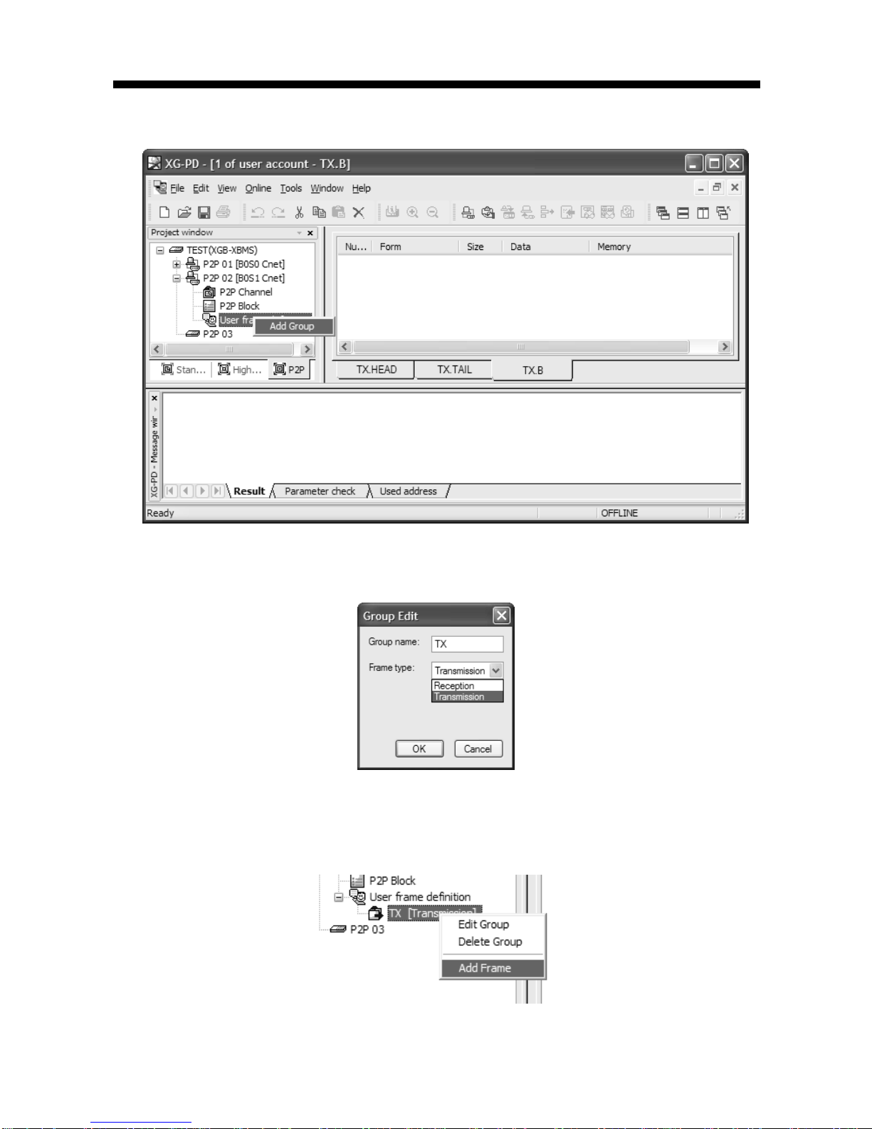
Chapter 6 Server function and P2P service
6-16
First, add group of transmission frame
[Figure 6.2.19] Transmission frame group add screen
If group edit window shows like the following, insert group name and select frame type
“Transmission”.
[Figure 6.2.20] transmission frame group setting screen
You can register diverse frame about each group. For this, select group to register transmission
frame and click right button of mouse and add frame.
[Figure 6.2.21] transmission frame add setting screen

Chapter 6 Server function and P2P service
6-17
By using frame edit window, you can register Head, Body, Tail
[Figure 6.2.22] transmission frame edit window
Only one Head and Tail exist about group but you can register many Bodies. Also you can omit
Head and Tail but one Body is necessary.
A) Head registration
Head can add many segments but in each segment numerical constant and string constant are
available
[Figure 6.2.23] Transmission frame Head registration screen
B) Body registration
Body can be configured many segments, you can define up to 4 variable sized variable.
In frame edit window, if you set Body about TX.FRM_A, it is as follows.
[Figure 6.2.24] Transmission frame Body registration screen
C) Tail registration
You can register BCC in this item. Supported BCC is as follows.

Chapter 6 Server function and P2P service
6-18
[Figure 6.2.25] Transmission frame Tail registration screen
The following is screen where transmission frame registration is complete.
[Figure 6.2.26] transmission frame setting complete screen
6) Reception frame
In case of receiving temporary frame, first you should define reception frame. In case of receiving
ACK, NAK response reception frame, registration method is as follows.
ACK.FRAME Head Body Ta il
Frame 0x06 01 wSB 03 BCC
Reference
Numerical
constant
String
constant
String
constant
Numerical
constant
Byte Check Sum
ASCII
NAK.FRAME Head Body Ta il
Frame 0x15 01 wSB
Fix sized
variable
03 BCC
Size (byte) 1 2 3 2 1 2
Reference
Numerical
constant
String
constant
String
constant
(Error code
saving area)
Numerical
constant
Byte Check
Sum ASCII

Chapter 6 Server function and P2P service
6-19
First, to register frame, add group as “ACK”, “NAK”.
[Figure 6.2.27] ACK, NAK reception group registration screen about wSB request frame
▪Adds frame registered reception frame group “ACK”.
A) Head registration
[Figure 6.2.28] ACK reception frame Head registration screen
B) Body registration
Registers at Body about data to process and instruction among reception frame
[Figure 6.2.29] ACK reception frame Body registration screen
C) Tail registration
[Figure 6.2.30] ACK reception frame Tail registration screen
▪ Registers frame at registered reception frame group “NAK”
A) Head registration
[Figure 6.2.31] NAK reception frame Head registration screen

Chapter 6 Server function and P2P service
6-20
B) Body registration
Registers at Body about data to process and instruction among reception frame
In case you know size of data to save among reception frame, use fix sized variable and in case
you don’t know size of data, use variable sized variable.
[Figure 6.2.32] NAK reception frame Body registration screen
C) Tail registration
[Figure 6.2.33] NAK reception frame Tail registration screen
Screen where ACK, NAK registration is complete is as follows.
[Figure 6.2.34] ACK, NAK reception frame registration complete screen

Chapter 6 Server function and P2P service
6-21
6.2.6 P2P service operation
If P2P parameter setting ends, you should download PLC CPU parameter and start P2P service.
We assume that P2P parameter to download is written and PLC is connected with CPU.
1) P2P parameter download
If you select “Online” ->”Write Parameter” of XG-PD menu window to download P2P parameter,
parameter download window shows. In case of communication parameter, you can’t select
individual parameter but all parameter is downloaded.
[Figure 6.2.35] P2P Parameter Write screen
If you press “OK”, it downloads P2P parameter to CPU.
2) P2P service start
Though you download P2P parameter, to start P2P service, you should start P2P. For this, select
“Online-Enable Link”.

Chapter 6 Server function and P2P service
6-22
[Figure 6.2.36] P2P enable setting screen
In the “Enable Link (HS Link, P2P)” window, select P2P parameter. Already checked P2P
parameter is under operation. If you uncheck, P2P service stops.
If you like to know whether P2P service is normal or not, select “Online -> System diagnosis”. For
this function, refer to “Chapter 9. system diagnosis”.

Chapter 7 XGT Dedicated Protocol
7-1
Chapter 7 XGT Dedicated Protocol
7.1 XGT Dedicated Protocol
7.1.1 General
XGT series dedicated protocol communication is function executing communication by our dedicated protocol.
User can configure the intended communication system between our products without special setting by using
reading/writing data of internal device area and monitoring function.
Dedicated protocol function supported by XGB is as follows.
Device individual/continuous read
Device individual/continuous write
Monitor variable registration
Monitor execution
1:1 connection (Our link) system configuration
XGB’s built-in communication function supports Cnet communication without any separate Cnet
I/F module. It must be used under the following instructions.
1) Channel 0 of XGB’s main unit supports 1:1 communication only. For 1:N system having master-
slave Format, use RS-485 communication in channel 1 or XGB’s main unit with XGL-C41A module
connected. XGL-C41A module supports RS-422/485 protocol.
2) RS-232C communication cable for XGB’s main unit is different from RS-232C cable for
XG5000 (XG-PD) in pin arrangement and from the cable for Cnet I/F module, too. The cable
can’t be used without any treatment. For the detailed wiring method, refer to configuration of
respective communication.
3) It’s possible to set baud rate type and station No. in XG5000 (XG-PD).
Note

Chapter 7 XGT Dedicated Protocol
7-2
7.1.2 Frame structure
(1) Base format
(a) Request frame (external communication device → XGB)
Header
(ENQ)
Station
number
Command
Command
type
Structurized data area
Tail
(EOT)
Frame check
(BCC)
(b) ACK response frame (XGB → external communication device, when receiving data normally)
Header
(ACK)
Station
number
Command
Command
type
Structurized data area or
Null code
Tail
(ETX)
Frame check
(BCC)
(c) NAK response frame (XGB → Cnet I/F module → external communication device when receiving
data abnormally)
Header
(NAK)
Station
number
Command
Command
type
Error code ( ASCII 4 Byte )
Tail
(ETX)
Frame check
(BCC)
1) The numerical data of all frames are ASCII codes equal to hexadecimal value, if there’s no clear
statement.
The terms in hexadecimal are as follows.
Station No.
When the main command is R(r) or W (w) and the command type is numerical (means a data type)
All of the terms indicating size of all data in the Formatted data area.
Monitoring registration and command registration number of execution commands.
All contents of data
2) If it is hexadecimal, H is attached in front of the number of frames like H01, H12345, H34, H12,
and H89AB.
3) Available frame length is maximum 256 bytes.
4) Used control codes are as follows.
5) If the command is small letter (r), BCC value is added in check frame. The other side capital
letter (R), BCC value is not added in check frame.
Codes Hex value Name Contents
ENQ H05 Enquire Request frame initial code
ACK H06 Acknowledge
ACK response frame initial code
NAK H15
Not
Acknowledge
NAK response frame initial code
EOT H04 End of Text Request frame ending ASCII code
ETX H03 End Text Response frame ending ASCII code
Note

Chapter 7 XGT Dedicated Protocol
7-3
(2) Command frame sequence
▪ Sequence of command request frame
ENQ
Stati
on
No.
Comma
nd
Formatted data
EOT BCC
ACK
Station
No.
Command Formatted data
ETX BCC
NAK
Station
No.
Command Formatted data
ETX BCC
7.1.3 List of commands
List of commands used in dedication communication is as shown below.
Items
Command
Treatment Main command Command type
Code ASCII code Code ASCII code
Reading
device
Individual
r(R)
H72
(H52)
SS 5353
Reads direct variable of Bit, Byte, Word, Dword, Lword type.
Continuous
r(R)
H72
(H52)
SB 5342
Read direct variable of Byte, Word, Dword, Lword with
block unit
(Bit continuous read is not allowed)
Writing
device
Individual
w(W)
H77
(H57)
SS 5353
Write data of Bit, Byte, Word, Dword, Lword at direct
variable
Continuous
w(W)
H77
(H57)
SB 5342
Write data of Byte, Word, Dword, Lword at direct
variable with block unit
(Bit continuous read is not allowed)
Item
Command
Treatment Main command
Register No
Code ASCII code
Monitoring
variable
register
x(X)
H78
(H58)
H00~H0F
Register device to monitor.
Execution of
monitoring
y(Y)
H79
(H59)
H00~H0F
Execute registered device to monitor.
It identifies capitals or small letters for main commands, but not for the others.
Note
(PLC ACK response)
Classification
Classification
(PLC NAK response)

Chapter 7 XGT Dedicated Protocol
7-4
7.1.4 Data type
It’s possible to read and write device in built-in communication. When device is used, be aware of data type.
Data type of device
• Available types of device
- XBM-DXXXS and XBC-DXXXH
Device “S” type range “H ” type r ange Size (Word) Remark
P P0 – P127 P0 – P1023 1024
Read/Write/Monitor available
M M0 – M255 M0 – M1023 1024 Read/Write/Monitor available
K K0 – K2559 K0 – K4095 4096 Read/Write/Monitor avai lable
F F0 – F255 F0 – F1023 1024
Read/Monitor available
T T0 – T255 T0 – T1023 1024 Read/Write/Monitor available
C C0 – C255 C0 – C1023 1024 Re ad/ Write/Monitor av ailable
L L0 – L1279 L0 – L2047 2048 Re ad/ Write/Monitor avai lable
N N0 – N3935 N0 – N5119 5120
Read/Monitor available
D D0 – D5119 D0 – D10239 10240 Read/Write/Monitor available
U U00.00 – U07.31 U00.00 – U0A.31 352 Read/Write/Monitor available
R - R0 – R10239 10240 Read/Write/Monitor available
- XEC-DXXXH
Device Range Size (Word) Remark
I %IW0.0.0 ~ %IW15.15.3 1024
Read/Write/Monitor available
Q %QW0.0.0 ~ %QW15.15.3 1024 Read/Write/Monitor available
M %MW0 ~ %MW8191 8192 Read/Write/Monitor available
W %WW0 ~ %WW10239 10240 Read/Write/Monitor available
R %RW0 ~ %RW10239 10240 Read/Write/Monitor available
F %FW0 ~ %FW1023 1024 Read/Monitor available
K %KW0 ~ %KW4095 4096 Read/Write/Monitor available
L %LW0 ~ %LW2047 2048 Read/Write/Monitor available
N %NW0 ~ %NW5119 5120
Read/Monitor available
U %UW0.0.0 ~ %UW0.15.31 512 Read/ Write/Monitor avai lable

Chapter 7 XGT Dedicated Protocol
7-5
When device is designated, attach ‘%’ (25H) in front of the marking characters.
(‘%’ is stands for starting of device.)
Data type
Marking
characters
Examples
Bit X(58H) %PX000,%MX000,%LX000,%KX000,%CX000,%TX000,%FX000 etc.
Byte B(42H) %PB000,%MB000,%LB000,%KB000,%CB000,%TB000,%FB000 etc.
Word W(57H)
%PW000,%MW000,%LW000,%KW000,%CW000,%TW000,%FW000,
%DW000 etc.
Dword D(44H)
%PD000,%MD000,%LD000,%KD000,%CD000,%TD000,
%FD000,%DD000 etc.
Lword L(4CH)
%PL000,%ML000,%LL000,%KL000,%CL000,%TL000,
%FL000,%DL000 etc.
Timer/Counter used in bit command means contact point values.
(word command means current values.)
Data register (D) can uses only word or byte commands.
In byte type commands, address is doubled. For example, D1234 is addressed to ‘%DW1234’
in word type, and is addressed to ‘%DB2468’ in byte type.
Note

Chapter 7 XGT Dedicated Protocol
7-6
7.1.5 Detail of instruction
(1) Individual reading of device (R(r)SS
)
(a) Purpose
This is a function that reads PLC device specified in accord with memory data type. Separate
device memory can be read up to 16 at a time.
(b) PC request format
Format
name
Header
Statio
n No.
Comma
nd
Command
type
Number
of
blocks
Device
length
Device name
....
Tail
Frame
check
Ex. of
frame
ENQ H20 R(r) SS H01 H06 %MW100 EOT BCC
ASCII
value
H05
H323
0
H52(72) H5353 H3031 H3036 H254D57313030 H04
Item Description
BCC
When command is lowercase(r), only one lower byte of the value resulted by adding
1 Byte each to ASCII values from ENQ to EOT is converted into ASCII and added to
BCC. For example, the BCC of the above frame is gotten as below:
H05+H32+H30+H72+H53+H53+H30+H31+H30+H36+H25+H4D+H57+H31+H30+H3
0+H04 = H03A4 Therefore BCC value is A4 (ASCII value : H4134).
Number of
Blocks
This specifies how much of the blocks composed of "[device length][device name]"
are in this request format. This can be set up to 16. Therefore, the value of [Number
of blocks] must be set between H01(ASCII value:3031)-H10(ASCII value:3030).
Device
length
(Length of
device
name)
This indicates the number of name's characters that means device, which is
allowable up to 16 characters. This value is one of ASCII converted from hex type,
and the range is from H01(ASCII value:3031) to H10(ASCII value:3130). For
example, if the device name is %MW0, it has 4 characters to be H04 as its length.
If %MW000 characters to be H06.
Device
name
Address to be actually read is entered. This must be ASCII value within 16
characters, and in this name, digits, upper/lower case, '%' is only allowable to be
entered.
BCC value is low 1byte in the sum of each byte from ENQ to EOT.
In case of making actual frame, 'H' is not attached. Because the number data of frame indicates
hexadecimal.
1 block (settin
g
can be repeated up to max. 16 blocks
)
Note

Chapter 7 XGT Dedicated Protocol
7-7
(c) XGB response format (ACK response)
Format name Header Station No. Command Command type
Number
of blocks
Number of
data
data
......
Tail
Frame
check
Ex. of frame ACK H20 R(r) SS H01 H02 HA9F3 ETX BCC
ASCII value H06 H3230 H52(72) H5353 H3031 H3032 H41394633 H04
1 block (max. 16 blocks possible)
Item Description
BCC
When command is lowercase(r), only one lower byte of the value resulted by
adding 1 Byte each to ASCII values from ACK to ETX is converted into ASCII and
added to BCC, and sent.
Number of
data
Number of data means byte number of hex type, and is converted into ASCII. This
number is determined according to data type (X,B,W) included in device name of
computer request Format.
Number of data in accordance with its data type is as follows:
Data type Available variable Number of data
Bit(X) %(P,M,L,K,F,T,C,D,R,I,Q,W)X 1
Byte(B) %(P,M,L,K,F,T,C,D,R,I,Q,W)B 1
Word(W) %(P,M,L,K,F,T,C,D,R,I,Q,W)W 2
※R area is supported at XBC-DXXXH
Data
In data area, there are the values of hex data converted to ASCII code saved.
▪ Example 1
The fact that number of data is H04 (ASCII code value:H3034) means that there is hex data of 4
bytes in data. Hex data of 4 bytes is converted into ASCII code in data.
▪ Example 2
If number of data is H04 and the data is H12345678, ASCII code converted value of this is "31
32 33 34 35 36 37 38," and this contents is entered in data area. Name directly, highest value is
entered first, lowest value last.
If data type is Bit, data read is indicated by bytes of hex. Namely, if Bit value is 0, it indicated
by H00, and if 1, by H01.
Note

Chapter 7 XGT Dedicated Protocol
7-8
(d) XGB response format (NAK response)
Format name
Heade
r
Station
No.
Command Command type
Error code
(Hex 2 Byte)
Tail Frame check
Ex. of frame NAK H20 R(r) SS H1132 ETX BCC
ASCII value H15 H3230 H52(72) H5353 H31313332 H03
Item Explanation
BCC
When command is lowercase(r), only one lower byte of the value resulted by adding 1 Byte each to
ASCII values from NAK to ETX is converted into ASCII and added to BCC.
Error code
Hex and 2 bytes (ASCII code, 4 bytes) indicate error type. Refer to 10.1.4 XGT dedicated
communication error codes and countermeasures.
(e) Example
This example supposes when 1 WORD from M20 and 1 WORD from P001 address of station No.1
are read
(At this time, it is supposed that H1234 is entered in M20, and data of H5678 is entered in P001.)
1) PC request format (PC → XGB)
Format name Header
Station
No.
Command
Comman
d type
Number of
blocks
Variable
length
Variable name
Device
length
Variable name
Tail
Frame
check
Ex. of frame ENQ H01 R(r) SS H02 H06 %MW020 H06 %PW001 EOT BCC
ASCII value H05 H3031 H52(72) H5353 H3032 H3036
H254D573032
30
H3036
H255057303030
31
H04
2) For ACK response after execution of command (PC ← XGB)
Format name Header
Station
No.
Command
Command
type
Number of
blocks
Number of
data
Data
Number of
data
Data
Tail
Frame
check
Ex. of frame ACK H01 R(r) SS H02 H02 H1234 H02 H5678 ETX BCC
ASCII value H06
H303
1
H52(72) H5353 H3032 H3032 H31323334 H3032 H35363738 H03
3) For NAK response after execution of command (PC ← XGB)
Format name Header Station No. Command Command type Error code
Tail
Frame
check
Ex. of frame NAK H01 R(r) SS Error code (2 Byte) ETX BCC
ASCII value H15 H3031 H52(72) H5353 Error code (4 Byte) H03
XGB main unit

Chapter 7 XGT Dedicated Protocol
7-9
(2) Direct variable continuous reading (R(r)SB)
(a) Purpose
This is a function that reads the PLC device memory directly specified in accord with memory data
type. With this, data is read from specified address as much as specified continuously.
(b) PC request format
Format
name
Head
er
Station
No.
Comman
d
Comman
d type
Device length Device
Number of data
Tail
Frame
check
Ex. of
frame
ENQ H10 R(r) SB H06 %MW100 H05 EOT
BCC
ASCII
value
H05
H3130 H52(72)
H5342 H3036
H254D5731
3030
H3035 H04
Number of data specifies the number to read according to the type of data. Namely, if the
data type of device is word and number is 5, it means that 5 words should be read.
In the number of data, you can use up to 60 words (120Byte).
Protocol of continuous reading of direct variable doesn't have number of blocks.
. Bit device continuous reading is not supported.
Item Description
BCC
When command is lowercase(r), only one lower byte of the value resulted by
adding 1 Byte each to ASCII values from ENQ to EOT is converted into
ASCII and added to BCC.
Device length
(Length of
device name)
This indicates the number of name's characters that means device, which is
allowable up to 16 characters. This value is one of ASCII converted from hex
type, and the range is from H01 (ASCII value:3031) to H10 (ASCII
value:3130).
Device name
Address to be actually read is entered. This must be ASCII value within 16
characters, and in this name, digits, upper/lowercase, and '%' only are
allowable to be entered.
(c) XGB response format (ACK response)
Format name Header
Station
No.
Command
Command
type
Number of
blocks
Number of
data
data Tail
Frame
check
Ex. of frame
ACK H10 R(r) SB H01 H02 H1122 ETX BCC
ASCII value
H06 H3130 H52(72) H5342 H3031 H3134 H31313232 H03
Note

Chapter 7 XGT Dedicated Protocol
7-10
Item Description
Number of data
It means byte number of hex type, and is converted into ASCII
Data type Available device Data size (Byte)
BYTE(B) %(P,M,L,K,F,T,C,D,R,I,Q,W)B 1
WORD(W) %(P,M,L,K,F,T,C,D,R,I,Q,W)W 2
DWord(D) %(P,M,L,K,F,T,C,D,R,I,Q,W)D 4
LWord(L) %(P,M,L,K,F,T,C,D,I,Q,W)L 8
※R area is supported at XBC-DXXXH
▪Example 1
When memory type included in variable name of computer request Format is W (Word), and
data number of computer request Format is 03, data number of PLC ACK response after
execution of command is indicated by H06 (2*03 = 06 bytes)Byte and ASCII code value 3036 is
entered in data area.
▪Example 2
In just above example, when data contents of 3 words are 1234, 5678, and 9ABC in order,
actual ASCII code converted values are 31323334 35363738 39414243, and the contents are
entered in data area.
(d) XGB response format (NAK response)
`
Format name
Heade
r
Station
No.
Command Command type
Error code
(Hex 2 Byte)
Tail Frame check
Ex. of frame
NAK H10 R(r) SB H1132 ETX BCC
ASCII value
H15 H3130 H52(72) H5342 H31313332 H03
Item Description
BCC
When command is lowercase(r), only one lower byte of the value resulted by
adding 1 Byte each to ASCII values from NAK to ETX is converted into ASCII and
added to BCC, and sent.
Error code
Hex and 2 bytes (ASCII code, 4 bytes) indicate error type. For the details, Refer to
9.1.4 XGT dedicated communication error codes and countermeasures.
(e) Example
This example supposes that 2 WORDs from M000 of station No. 10 is read
(It supposes that M000 = H1234, M001 = H5678.)
1) PC request format (PC → XGB)
Format name Header Station No. Command Command type Device length Device name Number of data
Tail
Frame check
Frame (Example)
ENQ H0A R(r) SB H06 %MW000 H02 EOT BCC
ASCII value
H05 H3041 H52(72) H5342 H3036
H254D3030
30
H3032 H04
2) For ACK response after execution of command (PC ← XGB)
Format name Header Station No. Command
Command
type
Number of
block
Number of
data
Data Tail
Frame
check
Frame (Example)
ACK H0A R(r) SB H01 H04 12345678 ETX BCC
ASCII value
H06 H3041 H52(72) H5342 H3031 H3034 H3132333435363738 03

Chapter 7 XGT Dedicated Protocol
7-11
3) For NAK response after execution of command (PC ← XGB)
Format name Header Station No. Command
Command type
Error code Tail BCC
Frame (Example)
NAK H0A R(r) SB Error code (2 Byte) ETX BCC
ASCII value
H15 H3041 H52(72) H5342 Error code (4 Byte) H03

Chapter 7 XGT Dedicated Protocol
7-12
(3) Individual writing of device (W(w)SS)
(a) Purpose
This is a function that writes the PLC device memory directly specified in accord with memory data
type.
(b) PC request format
Format name Header Station No.
Command
Command
type
Number of
blocks
Device
Length
Device Name
Data
.....
Tail
Frame
check
Frame (Example)
ENQ H20 W(w) SS H01 H06 %MW100 H00E2 EOT BCC
ASCII value H05 H3230 H57(77) H5353 H3031 H3036
H254D573130
30
H30304532 H04
1 block (setting can be repeated up to max. 16 blocks)
Item Description
BCC
When command is lowercase(r), only one lower byte of the value resulted by
adding 1 Byte each to ASCII values from ENQ to EOT is converted into ASCII
and added to BCC.
Number of
blocks
This specifies how much of the blocks composed of "[device length][device
name]" are in this request Format. This can be set up to 16. Therefore, the value
of [Number of blocks] must be set between H01(ASCII value:3031)-H10 (ASCII
value:3030).
Device
Length
(Name length of
device)
This indicates the number of name's characters that means device, which is
allowable up to 16 characters. This value is one of ASCII converted from hex
type, and the range is from H01 (ASCII value: 3031) to H10 (ASCII value:3130).
device
Address to be actually read is entered. This must be ASCII value within 16
characters, and in this name, digits, upper/lower case, and '%' only is allowable to
be entered.
Data
If the value to be written in %MW100 area is H A, the data Format must be
H000A. If the value to be written in %MW100 area is H A, the data Format must
be H000A. In data area, the ASCII value converted from hex data is entered.
▪Example 1
If type of data to be currently written is WORD, the data is H1234, ASCII code converted value of
this is "31323334" and this content must be entered in data area. Namely, most significant value
must be sent first, least significant value last.
Device data types of each block must be the same
If data type is Bit, the data to be written is indicated by bytes of hex. Namely, if Bit value is 0,
it must be indicated by H00 (3030), and if 1, by H01 (3031).
Note

Chapter 7 XGT Dedicated Protocol
7-13
(c) XGB Response format (ACK response)
Format name Header Station No.
Command Command type
Tail Frame check
Frame (Example)
ACK H20 W(w) SS ETX BCC
ASCII value H06 H3230 H57(77) H5353 H03
Item Description
BCC
When command is lowercase (r), only one lower byte of the value resulted by
adding 1 Byte each to ASCII values from ACK to ETX is converted into ASCII and
added to BCC, and sent.
(d) XGB Response format (NAK response)
Format name Header Station No. Command Command type
Error code
(Hex 2 Byte)
Tail Frame check
Frame (Example)
NAK H20 W(w) SS H4252 ETX BCC
ASCII value H15 H3230 H57(77) H5353 H34323532 H03
Item Description
BCC
When command is lowercase(r), only one lower byte of the value resulted by adding
1 Byte each to ASCII values from NAK to ETX is converted into ASCII and added to
BCC, and sent.
Error code
Hex and 2 bytes (ASCII code, 4 bytes) indicate error type. For the details, Refer to
10.1.4 XGT dedicated communication error codes and countermeasures.
(e) Example
This example supposes that "HFF" is written in M230 of station No. 1.
1) PC request format (PC → XGB)
Format name Header
Station
No.
Command
Command
type
Number
of blocks
Device
Length
Device Name Data
Tail
Frame
check
Frame (Example)
ENQ H01 W(w) SS H01 H06 %MW230 H00FF EOT BCC
ASCII value
H05 H3031 H57(77) H5353 H3031 H3036
H254D573233
30
H30304646 H04
2) For ACK response after execution of command (PC ← XGB)
Format name Header Station No. Command
Command type
Tail Frame check
Frame (Example)
ACK H01 W(w) SS ETX BCC
ASCII value
H06 H3031 H57(77) H5353 H03
3) For NAK response after execution of command (PC ← XGB)
Format name Header
Station
No.
Command
Command type
Error code
Tail Frame check
Frame (Example)
NAK H01 W(w) SS
Error code (2 Byte)
ETX BCC
ASCII value
H15 H3031 H57(77) H5353
Error code (4 Byte)
H03

Chapter 7 XGT Dedicated Protocol
7-14
(4) Continuous writing of device (W(w)SB)
(a) Purpose
This is a function that directly specifies PLC device memory and continuously writes data from
specified address as much as specified length.
(b) Request format
Format
name
Head
er
Station
No.
Command
Comma
nd type
Device
Length
Device name
Number
of data
Data
Tail
Frame
check
Frame
(Example)
ENQ H10 W(w) SB H06 %MW100 H02 H11112222 EOT BCC
ASCII
value
H05 H3130 H57(77) H5342
H3036 H254D573130
30
H3032
H31313131323232
32
H04
Number of data specifies the number according to the type of device. Namely, if the data type of
device is WORD, and number of data is 5, it means that 5 WORDs should be written.
Number of data can be used up to 120Bytes (60 Words).
Item Description
BCC
When command is lowercase(r), only one lower byte of the value resulted by
adding 1 Byte each to ASCII values from ENQ to EOT is converted into ASCII and
added to BCC.
Device
Length
(Name length of
variable)
This indicates the number of name's characters that means device, which is
allowable up to 16 characters. This value is one of ASCII converted from hex type,
and the range is from H01 (ASCII value: 3031) to H10 (ASCII value: 3130).
Device
Address to be actually read. This must be ASCII value within 16 characters, and in
this name, digits, upper/lower case, and '%' only are allowable to be entered.
(c) XGB Response format (ACK response)
Format name
Header
Station No.
Command Command type
Tail Frame check
Frame (Example)
ACK H10 W(w) SB ETX BCC
ASCII value
H06 H3130 H57(77) H5342 H03
Item Description
BCC
When command is lowercase(r), only one lower byte of the value resulted by adding 1
Byte each to ASCII values from ACK to ETX is converted into ASCII and added to
BCC, and sent.
Note

Chapter 7 XGT Dedicated Protocol
7-15
(d) XGB Response format (NAK response)
Format name Header Station No.
Command Command type
Error code (Hex 2 Byte)
Tail Frame check
Frame (Example)
ENQ H10 W(w) SB H1132 EOT BCC
ASCII value
H05 H3130 H57(77) H5342 H31313332 H03
Item Description
BCC
When command is lowercase(r), only one lower byte of the value resulted by adding
1 Byte each to ASCII values from NAK to ETX is converted into ASCII and added to
BCC, and sent.
Error code
Hex and 2 bytes (ASCII code, 4 bytes) indicate error type. For the details, Refer to
9.1.4 XGT dedicated communication error codes and countermeasures.
(e) Example
This example supposes that 2 byte H’AA15 is written in D000 of station No. 1.
1) PC request format (PC → XGB)
Format name Header
Station
No.
Command
Comman
d type
Device
Length
Device
Number of
data
Data Tail Frame check
Frame
(Example)
ENQ H01 W(w) SB H06 %DW000 H01 HAA15 EOT BCC
ASCII value
H05 H3031 H57(77) H5342 H3036
H2544573030
30
H3031 H41413135 H04
2) For ACK response after execution of command (PC ← XGB)
Format name Header Station No.
Command Command type
Tail Frame check
Frame (Example)
ACK H01 W(w) SB ETX BCC
ASCII value
H06 H3031 H57(77) H5342 H03
3) For NAK response after execution of command (PC ← XGB)
Format name Header Station No.
Command Command type
Error code
Tail Frame check
Frame
(Example)
NAK 01 W(w) SB
Error code (2)
ETX BCC
ASCII value
H15 H3031 H57(77) H5342
Error code (4)
H03

Chapter 7 XGT Dedicated Protocol
7-16
(5) Monitor variable register (X##)
(a) Purpose
Monitor register can separately register up to 16 (from 0 to 15) in combination with actual variable
reading command, and carries out the registered one through monitor command after registration.
(b) PC request format
Format name
Head
er
Station
No.
Comma
nd
Registratio
n No.
Registration
format
Tail Frame check
Frame
(Example)
ENQ H10 X(x) H09
Refer to
registration
format
EOT BCC
ASCII value H05 H3130 H58(78) H3039
Refer to *1
H04
Item Description
BCC
When command is lowercase(x), only one lower byte of the value resulted by
adding 1 byte each to ASCII values from ENQ to EOT is converted into ASCII,
added to BCC.
Register No.
This can be registered up to 16 (0 to 15, H00-H0F), and if an already registered
No. is registered again, the one currently being executed is registered.
Register
Format
This is used to before EOT in command of Formats of separate reading of
variable, continuous reading, and named variable reading.
*1 : Register Format of request Formats must select and use only one of the followings.
1) Individual reading of device
RSS
Number of blocks
(2
Byte)
Device length
(2 Byte)
Device name
(16 Byte) ...
1
block (max. 16 blocks)
2) Continuous reading of device
RSB Device length (2 Byte) Device name (16 Byte) Number of data
(c) XGB Response format (ACK response)
Format name Header Station No.
Command
Registration
no.
Tail Frame check
Frame (Example)
ACK H10 X(x) H09 ETX BCC
ASCII value
H06 H3130 H58(78) H3039 H03
Item Description
BCC
When command is lowercase(x), only one lower byte of the value resulted by
adding 1 Byte each to ASCII values from ACK to ETX is converted into ASCII and
added to BCC, and sent.

Chapter 7 XGT Dedicated Protocol
7-17
(d) XGB Response format (NAK response)
Format name Header Station No.
Command
Registratio
n No.
Error code
(Hex 2Byte)
Tail Frame check
Frame (Example)
NAK H10 X(x) H09 H1132 ETX BCC
ASCII value
H15 H3130 H58(78) H3039 H31313332 H03
Item Description
BCC
When command is one of lower case(x), only one lower byte of the value resulted
by adding 1 Byte each to ASCII values from NAK to ETX is converted into ASCII
and added to BCC, and sent.
Error code
Hex and 2 bytes (ASCII code, 4 bytes) indicate error type. For the details, Refer to
9.1.4 XGT dedicated communication error codes and countermeasures.
(e) Example
This example supposes that device M000 of station NO. 1 is monitor registered.
1) PC request format (PC → XGB)
Format name Header
Station
No.
Command
Registration
No.
Registration Format
Tail
Frame
check
R##
Number of
blocks
Device length Device name
Frame (Example)
ENQ H01 X(x) H01 RSS H01 H06 %MW000 EOT BCC
ASCII value
H05 H3031 H58(78) H3031
H5253
53
H3031 H3036
H2554573030
30
H04
2) For ACK response after execution of command (PC ← XGB)
Format name Header Station No. Command
Registration No.
Tail
Frame check
Frame (Example)
ACK H01 X(x) H01 ETX BCC
ASCII value
H06 H3031 H58(78) H3031 H03
3) For NAK response after execution of command (PC ← XGB)
Format name Header Station No. Command Registration No.
Error code
Tail
Frame check
Frame (Example)
NAK H01 X(x) H01 Error code (2) ETX BCC
ASCII value
H15 H3031 H58(78) H3031 Error code (4) H03

Chapter 7 XGT Dedicated Protocol
7-18
(6) Monitor execution (Y##)
(a) Purpose
This is a function that carries out the reading of the variable registered by monitor register. This
also specifies a registered number and carries out reading of the variable registered by the number.
(b) PC request format
Format name
Header
Station No. Command
Registration No.
Tail Frame check
Frame (Example)
ENQ H10 Y(y) H09 EOT BCC
ASCII value
H05 H3130 H59(79) H3039 H03
Item Description
Register
No.
Register No. uses the same number registered during monitor register for monitor
execution. It is possible to set from 00-09 (H00-H09).
BCC
When command is lower case(y), only one lower byte of the value resulted by
adding 1 byte each to ASCII values from ENQ to EOT is converted into ASCII,
added to BCC.
(c) XGB Response format (ACK response)
1) In case that the register Format of register No. is the Individual reading of device
Format name Header
Station
No.
Command
Registration
No.
Number of
Blocks
Number of data
Data Tail Frame check
Frame (Example)
ACK H10 Y(y) H09 H01 H02 H9183 ETX BCC
ASCII값
H06 H3130 H59(79) H3039 H3031 H3032 H39313833 H03
2) In case that the register Format of register No. is the continuous reading of device
Format name Header
Station No. Command
Registration No.
Number of
data
Data Tail
Frame check
Frame (Example)
ACK H10 Y(y) H09 H04 H9183AABB ETX BCC
ASCII value
H06 H3130 H59(79) H3039 H3034
H39313833414142
42
H03
(d) XGB Response Format (NAK response)
Format name
Head
er
Station
No.
Command
Registration
No.
Error code
(Hex 2Byte)
Tail Frame check
Frame (Example)
NAK H10 Y(y) H09 H1132 ETX BCC
ASCII value
H15 H3130 H59(79) H3039 H31313332 H03
Item Description
BCC
When command is lowercase(y), only one lower byte of the value resulted by
adding 1 Byte each to ASCII values from NAK to ETX is converted into ASCII and
added to BCC, and sent.
Error code
Hex and 2 bytes (ASCII code, 4 bytes) indicate error type. For the details, Refer to
9.1.4 XGT dedicated communication error codes and countermeasures.

Chapter 7 XGT Dedicated Protocol
7-19
(e) Example
This example supposes that registered device No. 1 of station No. 1 is read. and BCC value is
checked. And it is supposed that device M000 is registered and the number of blocks is 1.
1) PC request format (PC → XGB)
Format name
Header
Station No.
Command
Registration No.
Tail Frame check
Frame (Example)
ENQ H01 Y(y) H01 EOT BCC
ASCII value
H05 H3031 H59(79) H3031 H04
2) For ACK response after execution of command (PC → XGB)
Format name Header
Station
No.
Command
Registration
No.
Number of
Blocks
Number of data
Data Tail Frame check
Frame (Example)
ACK H01 Y(y) H01 H01 H02 H2342 ETX BCC
ASCII value
H06 H3031 H59(79) H3031 H3031 H3032 H32333432 H03
3) For NAK response after execution of command (PC → XGB)
Format name Header Station No. Command
Registration No.
Error code
Tail Frame check
Frame (Example)
NAK H01 Y(y) H01
Error code(2)
ETX BCC
ASCII value
H15 H3031 H59(79) H3031
Error code(4)
H03

Chapter 8 LS Bus Protocol
8-1
Chapter 8 LS Bus Protocol
8.1 LS Bus Protocol
LS Bus Protocol communication is function executing communication between XGB Cnet an d LS Inverte r .
User can configure LS Bus communication system between our products without special setting by using
reading/writing data of internal device area and monitoring function.
The function of LS Bus Protocol supported by XGB is as follows.
Device continuous reading
Device continuous writing
8.1.1 Frame structure
1) Base format
(a) Request frame (External communication → XGB)
Header
(ENQ)
Station
number
Command Structurized data area
Frame check
(BCC)
Tail
(EOT)
(b) ACK response frame (XGB → External communication, when receiving da ta nor mally )
Header
(ACK)
Station
number
Command Structurized data area
Frame check
(BCC)
Tail
(EOT)
(c) NAK response frame (XGB → External communication, when receiving data abnormally)
Header
(NAK)
Station
number
Command Error code ( ASCII 4 By te )
Frame check
(BCC)
Tail
(EOT) Note
1) The numerical data of all frames are ASCII codes equal to hexadecimal value, if there’s no clear statement.
The terms in hexadecimal are as follows.
• Station No.
• Command type is supported R (read) and W (write).
• All contents of data
2) If it is hexadecimal, H is attached in front of the number of frames like H01, H12345, H34, H12, and H89AB.
3) Available frame length is maximum 256 bytes.
4) Used control codes are as follows.
Code Hex value Name Contents
ENQ H05 Enquire Request frame initial code
ACK H06 Acknowledge ACK response frame initial code
NAK H15 Not Acknowledge NAK response frame initial code
EOT H04 End of T ext Request frame ending ASCII code

Chapter 8 LS Bus Protocol
8-2
2) Command frame sequence
▪ Sequence of command request frame
ENQ
Station
No.
Command Formatted data BCC EOT
ACK
Station
No.
Command Formatted data BCC EOT
NAK
Station
No.
Command Formatted data BCC EOT
8.1.2 List of commands
List of commands used in LS Bus communication is as shown below.
Items
Command
Treatment
Comman d type
Code ASCII code
Continuous read R H52 Read inverter variable of Word.
Continuous write W H57 Write inverter variable of Word.
(Inverter ACK response)
(Inverter NAK response)
Classification

Chapter 8 LS Bus Protocol
8-3
8.2 Detail of instruction
8.2.1 Continuous writing to inverter device (W)
This command is to write PLC data in specified address of inverter.
LS Bus Client Request format
Format
name
Header
Station
No.
Command
Device
Length
Address of
inverter
Data .....
Frame
check
Tail
Frame
(Example)
ENQ H20 W H6 0100 H00E2 - BCC EOT
ASCII
value
H05 H3230 H57 H36 H30313030 H30304532 - - H04
Item Description
BCC
When ASCII value of each 1byte except ENQ and EOT is summ ed, the lowest 1byte of the r esult
value is BCC.
Device
Length
This specifies how many Words you will writ e.
As converted value to ASCII, the range is from H01
(ASCII value: 3031) to H08 (ASCII value: 3038).
Address of inverter
Enter the address that you want to read. ASCII value above 4 character s and non-
numeric is not
allowed.
Data When you write data H'A to inverter address 0100 area, the data format has to be H000A.
Example)
If you want to write H1234 , 31323 334 (C onver ted va lue to ASCI I) sho uld be inc lude d in the data area. So , the
highest value has to be sent first and the lowest value has to be sent last.
Note
• Device data of Word type is only supported.

Chapter 8 LS Bus Protocol
8-4
Inverter Response format(ACK response)
Format name Header
Station
No.
Command Data Frame check Tail
Frame (Example) ACK H20 W H00E2 … BCC EOT
ASCII value H06 H3230 H57 H30304532 - - H04
Item Description
BCC
When ASCII value of each 1byte except ENQ and EOT is summ ed, the lowes t 1byte of the r esult
value is BCC.
Inverter Response format(NAK response)
Format name Header Station No. Command
Error code
(ASC 2 Byte)
Frame
check
Tail
Frame (Example) NAK H20 W H12 BCC EOT
ASCII value H15 H3230 H57 H3132 - H04
Item Description
BCC
When ASCII val ue of each 1byte exc ept ENQ an d EOT is summed, the l owest 1byte of the result
value is BCC.
Error code
Error information is shown as hex 1byte (2bytes of ASCII code).
For more information, please refer to the error code of the inverter user manual.
Example
This describes if the user want to write "H00FF" to address number 1230 of station number 1 of inverter.
XGB request format (XGB → Inverter)
Format name Header
Station
No.
Command
Device
length
Address of
inverter
Data Frame check Tail
Frame (Example)
ENQ
H01 W H1
1230
H00FF
BCC
EOT
ASCII value
H05
H3031
H57
H3031
H31323330
H30304646
-
H04
For ACK response after execution of command (XGB ← Inverter)
Format name Header Statio n No. Command Data Frame check Tail
Frame (Example) ACK H01 W H00FF BCC EOT
ASCII value H06 H3031 H57 H30304646 - H04
For NAK response after execution of command (XGB ← Inverter)
Format name Header Station No. Command Error code Frame check Tail
Frame (Example)
NAK
H01 W H12
BCC
EOT
ASCII value
H15
H3031
H57
Error code (2 Byte)
-
H04

Chapter 8 LS Bus Protocol
8-5
8.2.2 Inverter continuous reading (R)
This is a function of continuous reading of designated amount of PLC data from designated address number.
PC Request format
Format name Header
Station
No.
Command
Address of
inverter
Number of data
Frame
check
Tail
Frame (Example)
ENQ
H10 R 0100
H5
BCC
EOT
ASCII value
H05
H3130
H52
H30313030
H35
-
H04
Item Description
BCC
When ASCII val ue of each 1byte except ENQ and EOT is summed, th e lowest 1b yte of the
result value is BCC.
Device length
This specif ies ho w many Words you wi ll wri te. As co nv er t ed v al ue t o ASC II , t he r an ge is from
H01 (ASCII value: 3031) to H08 (ASCII value: 3038).
Address of inverter
Enter the addr ess that you want to r ead. ASC II v alue abo ve 4 char acters an d no n-numeric is
not allowed.
Note
• Device data of Word type is only supported.
 Loading...