


User’s Manual
○○○○○○ Series
XGB Hardware (IEC)
Programmable Logic C ontroller
XGT Series
XEC-
DR32H
XEC-
DN32H
XEC-
DP32H
XEC-
DR64H
XEC-
DN64H
XEC-
DP64H
XEC-
DR32H/D1
XEC-
DR64H/D1

Safety Instruction
Before using the product …
For your safety and effective operation, please read the safety instructions
thoroughly before using the product.
► Safety Instructions should always be observed in order to prevent accident
or risk with the safe and proper use the product.
► Instructions are separated into “Warning” and “Caution”, and the meaning of
the terms is as follows;
This symbol indicates the possibility of serious injury
or death if some applicable instruction is violated
This symbol indicates the possibility of slight injury
or damage to products if some applicable instruction
is violated
► The marks displayed on the product and in the user’s manual have the
following meanings.
Be careful! Danger may be expected.
Be careful! Electric shock may occur.
► The user’s manual even after read shall be kept available and accessible to
any user of the product.
Warning
Caution

Safety Instruction
Safety Instructions when designing
Please, install protection circuit on the exterior of PLC to protect
the whole control system from any error in external power or PLC
module. Any abnormal output or operation may cause serious problem
in safety of the whole system.
- Install applicable protection unit on the exterior of PLC to protect
the system from physical
damage such as emergent stop switch,
protection circuit, the upper/lowest limi
t switch, forward/reverse
operation interlock circuit, etc.
- If any system error (watch-dog timer error, module installation error,
etc.) is detected during CPU operation in PLC, the whole output is
designed to be turned off and stopped for system safety. However,
in case CPU error if caused on output device itself such as relay or
TR can not be
detected, the output may be kept on, which may
cause serious problems. Thus, you are recommended to install an
addition circuit to monitor the output stat us .
Never c onnect the overload than rated to the output module nor
allow the output circuit to have a short circuit, which may cause a
fire.
Never let the external power of the output circuit be designed to
be On earlier than PLC power, which may cause abnormal output or
operation.
In case of data exchange between computer or other external
equipment and PLC through communication or any operation of
PLC (e.g. operation mode change), please install interlock in the
sequence program to protect the system from any error. If not, it
may cause abnormal output or operation.
Warning

Safety Instruction
Safety Instructions when designing
Safety Instructions when designing
I/O signal or communication line shall be wired at least 100mm
away from a high-voltage cable or power line. If not, it may cause
abnormal output or operation.
Caution
Use PLC only in the environment specified in PLC manual or
general standard of data sheet. If not, electric shock, fire, abnormal
operation of the product or flames may be caused.
Before installing the module, be sure PLC power is off. If not,
electric shock or damage on the product may be caused.
Be sure that each module of PLC is correctly secured. If the
product is installed loosely or incorrectly, abnormal operation, error or
dropping may be caused.
Be sure that I/O or extension connecter is correctly secured. If
not, electric shock, fire or abnormal operation may be caused.
If lots of vibration is expected in the installation environment,
don’t let PLC directly vibrated. Electric shock, fire or abnormal
operation may be caused.
Don’t let any metallic foreign materials inside the product, which
may cause electric shock, fire or abnormal operation..
Caution

Safety Instruction
Safety Instructions when wiring
Prior to wiring, be sure that power of PLC and external power is
turned off. If not, electric shock or
damage on the product may be
caused.
Before PLC system is powered on, be sure that all the covers of
the terminal are securely cl osed . If not, electric shock may be caused
Warning
Let the wiring installed correctly after checking the voltage rated
of each product and the arrangement of terminals. If not, fire,
electric shock or abnormal operat ion may be caused.
Secure the screws of terminals tightly with specified torque when
wiring. If the screws of terminals get loose, short circuit, fire or abnormal
operation may be caused.
*
Surely use the ground wire of C lass 3 for FG terminal s, which is
exclusively used for PLC. If the terminals not grounded correctly,
abnormal operation may be caused.
Don’t let any foreign materials such as wiring waste inside the
module while wiring, which may cause fire, damage on the product
or abnormal operation.
Caution

Safety Instruction
Safety Instruct ions for test-operation or repair
Safety Instructions for waste disposal
Don’t touch the terminal when powered. Electric shock or abnormal
operation may occur.
Prior to cleaning or tightening the terminal screws, let all the
external power off including PLC power.
If not, electric shock or
abnormal operation may occur .
Don’t let the battery recharged, disassembled, heated, short or
soldered. Heat, explosion or ignition may cause injuries or fire.
Warning
Don’t remove PCB from the module case nor remodel the module.
Fire, electric shock or abnormal operation may occur.
Prior to installing or disassembling the module, let all the external
power off including PLC power. If not, electric shock or abnormal
operation may occur.
Keep any wireless installations or cell phone at least 30cm away
from PLC. If not, abnormal operatio n may be caused.
Caution
Product or battery waste shall be processed as industrial waste.
The waste may discharge toxic materials or explode itself.
Caution

Revision History
V
ersion Date Remark Chapter
V 1.0 2009.2
1. First Edition -
V 1.1 2009.6
1. Add detailed description on High Speed Counter
specification
Ch8.1.1
V 1.2 2009.10
1. Add DC power unit
Ch2.1, Ch2.2
Ch4.1, Ch4.3
Ch7.2.1, Ch7.2.2
Ch8.1.1, Ch8.1.2
Appendix2
V1.5 2010.10
1. Add new module
2. Error in consumption current calculation fixed
3. Error in Momentary power failure and watch dog
fixed
4. Error in program execution fixed
5. Error in memory unit fixed
6. Error in remote function fixed
7. RTC flag, setting method modified
8. Input speciation of main unit fixed
9. Contents related with XGI deleted
10. Voltage reference fixed
11. Contents related with STOP LED deleted
12. APM_SSSB modified
13. XEC-DP32H/DP64H added
Ch2.1, Ch2.2,
Ch2.3.1, Ch4.1
Ch4.3, Ch4.4
Ch5.1.2, Ch5.1.4
Ch5.2.2
Ch5.4.1
Ch6.4
Ch6.12
Ch7.2.1, Ch7.2.2
Ch10.2
Ch10.3
Ch.11
Appendix4
Ch4.1, Ch4.3
Ch7.3.4, Ch7.3.6
Appendix2
V1.6 2014.2
1. Domain Of Homepage Changed
2. Add XEC-DN32H/DC
Front/Back
Cover
Ch2.1, Ch2.2
Ch4.1, Ch4.3
Ch7.2.1, Ch7.3.3
Ch8.1.1
Appendix2
V1.7 2015.7
1. Address & phone number changed
2. Add new module
3. Vibration Specification modified
Back Cover
Ch2.1, Ch2.2,
Ch2.3.3, Ch2.3.4
Ch3.1
The number of User’s manual is indicated the right side of the back cover.
ⓒ LSIS Co. ,Ltd. 2009 All Rights Reserved.

About User’s Manual
About User’s Manual
Thank you for purchasing PLC of LSIS Co.,Ltd.
Before use, make sure to carefully read and understand the User’s Manual about the functions,
performances, installation and programming of the product you purchased in order for correct use and
importantly, let the end user and maintenance administrator to be provided with the User’s Manual.
The Use’s Manual describes the product. If necessary, you m ay refer to the following description and order
accordingly. In addition, you m ay connec t our website(http://eng.lsis.biz/
) and downlo ad the information as a
PDF file.
Relevant User’s Manual
Title Description
No. of User
Manual
XG5000 User’s
Manual
(XGI/XGR/XEC)
It describes how to use XG5000 software especially about
online functions such as programming, printing, monitoring
and debugging by using XGB (IEC language)
10310000512
XGI/XGR/XEC Series
Instruction &
Programming
It describes how to use the instructions for programming
using XGB (IEC language) series.
10310000510
XGB Hardware
User’s Manual (IEC
language)
It describes how to use the specification of power/input
/output/expansion m odules, system configuration and built-in
High-speed counter for XGB main unit.
10310000983
XGB Analog
User’s Manual
It describes how to use the specification of analog
input/analog output/temperature input module, system
configuration and built-in PID control for XGB main unit.
10310000920
XGB Position
User’s Manual
It describes how to use bu ilt-in positioning function for XGB
main unit.
10310000927
XGB Cnet I/F
User’s Manual
It describes how to use built-in communication function for
XGB main unit and external Cnet I/F module.
10310000816
XGB Fast Ethernet I/F
User’s Manual
It describes how to use XGB FEnet I/F module.
10310000873

◎
Contents
◎
Chapter 1 Introduction ...................................................................... 1-1~1-5
1.1 Guide to Use This Manual ...................................................................................... 1-1
1.2 Features ................................................................................................................ 1-2
1.3 Terminology ........................................................................................................... 1-4
Chapter 2 System Configuration ........................................................... 2-1~2-11
2.1 XGB System Configuration .................................................................................. 2-1
2.2 Product List .......................................................................................................... 2-2
2.3 Classification and Type of Product Name ............................................................. 2-4
2.3.1 Classification and type of main unit .......................................................................... 2-4
2.3.2 Classification and type of expansion module ........................................................... 2-5
2.3.3 Classification and type of special module ................................................................. 2-6
2.3.4 Classification and type of communication module ..................................................... 2-7
2.3.5 Classification and Type of Option Module ................................................................ 2-7
2.4 System Configuration ........................................................................................... 2-8
2.4.1 Cnet I/F system .......................................................................................................... 2-8
2.4.2 Ethernet system ........................................................................................................ 2-11
Chapter 3 General Specifications ................................................................. 3-1
3.1 General Specifications ........................................................................................... 3-1
Chapter 4 CPU Specifications ................................................................. 4-1~4-9
4.1 Performance Specifications .................................................................................. 4-1
4.2 Names of Part and Function ................................................................................. 4-3
4.3 Power Supply Specifications ................................................................................ 4-4
4.4 Calculation Example of Consumption Current/Voltage ........................................... 4-6

4.5 Battery ................................................................................................................. 4-8
4.5.1 Battery specification ................................................................................................... 4-8
4.5.2 Notice in using ............................................................................................................ 4-8
4.5.3 Life of battery .............................................................................................................. 4-8
4.5.4
How to change the battery ......................................................................................... 4-9
Chapter 5 Program Configuration and Operation Method .................. 5-1~5-28
5.1 Program Instruction .............................................................................................. 5-1
5.1.1 Program execution methods .................................................................................... 5-1
5.1.2 Operation processing during momentary power failure ........................................... 5-2
5.1.3 Scan time .................................................................................................................. 5-3
5.1.4 Scan Watchdog timer ............................................................................................... 5-4
5.2 Program Execution ............................................................................................... 5-5
5.2.1 Configuration of program .......................................................................................... 5-5
5.2.2 Program execution methods ...................................................................................... 5-5
5.2.3 Interrupt . .................................................................................................................... 5-7
5.3 Operation Mode ................................................................................................. 5-19
5.3.1 RUN mode .............................................................................................................. 5-19
5.3.2 STOP mode ............................................................................................................ 5-20
5.3.3 DEBUG mode ......................................................................................................... 5-20
5.3.4 Change operation mode ......................................................................................... 5-24
5.4 Memory ................................................................................................................ 5-25
5.4.1 Program memory .................................................................................................... 5-25
5.4.2 Data memory ............................................................................................................ 5-26
5.4.3 Data retain area setting .......................................................................................... 5-26
5.4.4 Data Memory Map .................................................................................................... 5-28
Chapter 6 CPU Functions ...................................................................... 6-1~6-24
6.1 Type Setting ......................................................................................................... 6-1
6.2 Parameter Setting ................................................................................................ 6-2
6.2.1 Basic parameter setting ............................................................................................ 6-2
6.2.2 I/O parameter setting ................................................................................................ 6-3
6.3 Self-diagnosis Function ........................................................................................ 6-4

6.3.1 Saving of error log .................................................................................................... 6-4
6.3.2 Troubleshooting ........................................................................................................ 6-4
6.4 Remote Functions .................................................................................................. 6-6
6.5 Forced Input/Output On and Off Function .............................................................. 6-7
6.5.1 Force I/O setup ......................................................................................................... 6-7
6.5.2 Processing time and method of Forced Input/Output On and Off ............................ 6-8
6.6 Direct Input/Output Operation ................................................................................ 6-9
6.7 Diagnosis of External Device ...............................................................................
6-10
6.8 Allocation of Input/Output Number .......................................................................
6-11
6.9 Online Editing ......................................................................................................
6-13
6.10 Reading Input/Outpu t Information ...................................................................... 6-16
6.11 Monitoring ........................................................................................................ 6-17
6.12
RTC function ...................................................................................................... 6-22
6.12.1 How to use ............................................................................................................ 6-22
Chapter 7 Input/Output Specifications ............................................... 7-1~7-31
7.1 Introduction .......................................................................................................... 7-1
7.2 Digital Input Specifications of Main Unit ................................................................ 7-7
7.2.1 XEC-DR32H / XEC-DN32H input unit (Source/Sink type) ......................................... 7-7
7.2.2 XEC-DR64H / XEC-DN64H input unit (Source/Sink Type) ........................................ 7-8
7.3 Digital Output Specification of Main Unit ............................................................... 7-9
7.3.1 XEC-DR32H output unit ............................................................................................. 7-9
7.3.2 XEC-DR64H output unit ........................................................................................... 7-10
7.3.3 XEC-DN32H output unit (Sink type) ......................................................................... 7-11
7.3.4 XEC-DP32H output unit (Source type) .................................................................... 7-12
7.3.5 XEC-DN64H output unit (Sink type) ......................................................................... 7-13
7.3.6 XEC-DP64H output unit (Source type) .................................................................... 7-14
7.4 Digital Input Module Specification ....................................................................... 7-15
7.4.1 8 point DC24V input module (Source/Sink type) .................................................... 7-15
7.4.2 16 point DC24V input module (Sink/Source type) .................................................. 7-16
7.4.3 32 point DC24V input module (Source/Sink type) ................................................... 7-17
7.5 Digital Output Module Specifications .................................................................. 7-18
7.5.1 8 point relay output module ...................................................................................... 7-18
7.5.2 16 point relay output module .................................................................................... 7-19
7.5.3 8 point transistor output module (Sink type) ............................................................ 7-20

7.5.4 16 point transistor output module (Sink type) .......................................................... 7-21
7.5.5 32 point transistor output module (Sink type) .......................................................... 7-22
7.5.6 8 point transistor output module (Source type) ........................................................ 7-23
7.5.7 16 point transistor output module (Source type) ...................................................... 7-24
7.5.8 32 point transistor output module (Source type) ...................................................... 7-25
7.6 Combined Module Digital Input Specification ....................................................... 7-26
7.6.1 8 point DC24V input part (Source/Sink type) ........................................................... 7-26
7.7 Combined Module Digital Output Specification ..................................................... 7-27
7.7.1 8 point relay output part ........................................................................................... 7-27
7.8 IO Wiring by Using Smart Link Board ................................................................... 7-28
7.8.1 Smart link board ..................................................................................................... 7-28
Chapter 8 Built-in High-speed Counter Function .............................. 8-1~8-32
8.1 High-speed Counter Specifications ........................................................................ 8-1
8.1.1 Performance specifications ...................................................................................... 8-1
8.1.2 Designation of parts .................................................................................................. 8-2
8.1.3 Counter Function ........................................................................................................ 8-4
8.2 Installation and Wiring ........................................................................................ 8-21
8.2.1 Precaution for wiring ............................................................................................... 8-21
8.2.2 Example of wiring ................................................................................................... 8-21
8.3 Internal Memory ................................................................................................. 8-22
8.3.1 Special area for High-speed counter ...................................................................... 8-22
8.3.2 Error code ............................................................................................................... 8-27
8.4 Examples: Using High-speed Counter ................................................................ 8-28
Chapter 9 Installation and Wiring ........................................................ 9-1~9-18
9.1 Safety Instruction ................................................................................................. 9-1
9.1.1 Fail safe circuit .......................................................................................................... 9-3
9.1.2 PLC heat calculation .................................................................................................. 9-6
9.2 Attachment/Detachment of Modules ..................................................................... 9-8
9.2.1 Attachment/Detachment of modules ....................................................................... 9-8
9.2.2 Caution in handling .................................................................................................. 9-13
9.3 Wire ..................................................................................................................... 9-14

9.3.1 Power wiring ............................................................................................................. 9-14
9.3.2 I/O Device wiring ...................................................................................................... 9-17
9.3.3 Grounding wiring ...................................................................................................... 9-17
9.3.4 Specifications of wiring cable ................................................................................... 9-18
Chapter 10 Maintenance .................................................................... 10-1~10-2
10.1 Maintenance and Inspection ............................................................................. 10-1
10.2 Daily Inspection ................................................................................................ 10-1
10.3 Periodic Inspection ........................................................................................... 10-2
Chapter 11 Troubleshooting ............................................................ 11-1~11-12
11.1 Basic Procedure of Troubleshooting ................................................................. 11-1
11.2 Troubleshooting .................................................................................................. 11-1
11.2.1 Troubleshooting flowchart used with when the PWR(Power) LED turns Off. ........ 11-2
11.2.2 Troubleshooting flowchart used with when the ERR(Error) LED is flickering ....... 11-3
11.2.3 Troubleshooting flowchart used with when the RUN,STOP LED turns Off. ......... 11-4
11.2.4 Troubleshooting flowchart used with when the I/O part doesn’t operate norm all y..11-5
11.3 Troubleshooting Questionnaire ......................................................................... 11-7
11.4 Troubleshooting Examples ............................................................................... 11-8
11.4.1 Input circuit troubles and corrective actions ......................................................... 11-8
11.4.2 Output circuit and corrective actions ...................................................................... 11-9
11.5 Error Code List .................................................................................................. 11-11
Appendix 1 Flag List ............................................................. App. 1-1~App.1-8
Appendix 1.1 Special Relay (F) List ..................................................................... App. 1-1
Appendix 1.2 Communication Relay (L) List ........................................................ App. 1-5
Appendix 1.3 Network Register (N) List .............................................................. App. 1-8
Appendix 2 Dimension ............................................................. App.2-1~App.2-4
Appendix 3 Compatibility with GLOFA ................................... App.3-1~App.3-7

Appendix 4 Instruction List ................................................... App.4-1~App.4-13
Appendix 4.1 Basic Function ................................................................................. App.4-1
Appendix 4.2 MK(MASTER-K) Function ............................................................. App.4-10
Appendix 4.3 Array Operation Function ............................................................. App.4-10
Appendix 4.4
Basic Function Block................................................................... App.4-11

Chapter 1 Introduction
Chapter 1 Introduction
1.1 Guide to Use This Manual
This manual includes specifications, functions and handling instructions for the XGB series PLC.
This manual is divi ded up into chapters as follows.
No. Title Contents
Chapter 1 Introduction
Describes configuration of this manual, unit’s features and
terminology.
Chapter 2 System Configurations
Describes available units and system configuration in the XGB
series.
Chapter 3 General Speci ficati on s
Describes general specifications of units used in
the XGB
series.
Chapter 4 CPU Specifications
Describes performances, specifications and operations.
Chapter 5
Program
Configuration and
Operation Method
Chapter 6 CPU Module Functions
Chapter 7 Input/Output Specifications Describes operation of basic and input/output.
Chapter 8
Built-in High-speed Cou nter
Function
Describes built-in high-speed counter functions.
Chapter 9 Installation and Wiring
Describes installation, wiring and handling instructions for
reliability of the PLC system.
Chapter 10
Maintenance
Describes the check items and method for long-
term normal
operation of the PLC system.
Chapter 11
Troubleshooting Describes various operation errors and corrective actions.
Appendix 1 Flag List Describes the types and contents of various flags.
Appendix 2 Dimension Shows dimensions of the main units and expansion modules.
Appendix 3
Compatibility with
GLOFA
Describes the compatibility with GLOFA.
Appendix 4 Instruction List Describes the special relay and instruction list.
1-1

Chapter 1 Introduction
1.2 Features
The features of XGB system are as follows.
(1) The system secures the following high performances.
(a) High Processing Speed
(b) Max. 384 I/O control supporting small & mid-sized system implement ation
Item Specification Reference
Operation processing
speed
83ns / Step -
Max IO contact point 384 points
Program capacity 200KB -
Max. no. of expanded
base
10 stages -
(c) Enough program capacity
(d) Expanded appli cation s with the suppo rt of float ing poi nt.
(2) Compact : the smallest size comparing to the same class model of competitors.
(a) Compact panel realiz ed thr ough the smallest size.
Item Type Size (W * H * D)
Reference
Main unit
XEC-Dx32H 114 * 90 * 64
XEC-Dx64H 180 * 90 * 64
Extension module XBE-,XBF-,XBL- 20 * 90 * 60 Basis of minimum size
(3) Easy attachable/extensible system for improved user convenience.
(a) Easy attachable to European terminal board and convenient-to-use MIL connector method improving
convenient wirin g. (“S” type main unit and expanded module)
(b) By adopting a removable terminal block connector (M3 X 6 screw), convenience of wiring may be
increased.
(c) By adopting connector coupling method, modules may be easily connected and separated.
(4) Improved maintenance ability with kinds of regis ter, built-in RTC (“H” type), comment backup and etc
(a) Convenient programmin g envir onment by p rovidin g analogu e regi ster, array and structure.
(b) Improved maintenance ability by operating plural programs and task program through module program.
(c) Built-in Flash ROM enabling permanent backup of program without any separate battery.
(d) Improved mainte nance ability by ty pes o f comme nt ba ckup.
(e) Built-in RTC function enabling convenient history and schedul e manage ment
1-2

Chapter 1 Introduction
(5) Optimized communication environment.
(a) With max. 2 channels o f built-in COM (excl. lo ade r) , up to 2 channel communication is available withou t
any expanded of module.
(b) Supporting various p rotocol s to improv e the conveni en ce (leaseddedicated, Modbus, user-defined
communication)
(c) Communication module may b e addi tio nal ly in c rea sed by ad di ng modules (up to 2 rackstages such as
Cnet, Enet and etc).
(d) Convenient network-diagnostic function through network & communication frame monitoring.
(e) Convenient networking to upper systems through Enet or Cnet.
(f) High speed p rogr am upload and download by USB P or t
(6) Applications expanded with a variety of I/O modules.
(a) 8, 16, 32 points modules provided (if relay output, 8/16 points module).
(b) Single input, single output and combined I/O modules supported.
(7) Applications expanded through analogue-exclusive dedicated register de sign and ful l attachable
mechanism.
(a) All analogue modules can be attachable on extension base. (H type: up to 10 racks stages available)
(b) W ith anal ogue exclusive dedicated re gister(U) and monitor ing exclusive dedicated function, convenient
use for I /O is maximize d (can design ate operations using eas y programming of U area and moni toring
function)
(8) Integrated programming environment
(a) XG 5000: intensified progr am conveni en ce, diver se monito ring, dia gnosi s and editin g functi on
(b) XG - PD: COM/network parameters setting, frame monitoring, protocol analysis function
(9) Built-in high speed counter function
(a) Providing high High-speed counter 1phase, 2phase and more additional func tions.
(b) Providing parameter setting, diverse moni tori ng and diagno sis fun ction using XG500 0.
(c) Moni torin g func tio n in X G500 0 ca n insp ect w ith out pro gram , ins pect ing ex ter nal w iring, data sett ing a nd
others.
(마침표)
(10) Built-in position control function
(a) Supporting max 100Kpps 2 axes.
(b) Providing parameter setting, operation data collection, diverse monitoring and diagnosis by using
XG5000.
(c) Commissioning by monitoring of XG5000, without program, inspecting external wiring and operation data
setting.
1-3

Chapter 1 Introduction
(11) Built-in PID
(a) Supporting max. 16 loops.
(b) Setting parameters by using XG5000 and supporting loop status monitoring conveniently with trend
monitor.
(c) Control constant setting through the improved automatic Auto-tuning function.
(d) With many other additional functions including PWM output, ∆MV, ∆PV and SV Ramp, improving the
control preciseness.
(e) Supporting types of cont rol m odes suc h as for ward/ back ward m ix ed o perat ion, 2-stage SV PID control,
cascade control and etc .
(f) A variety of warning functions such as PV MAX and PV variation warning securing the safety.
1.3 Terminology
The following table gives defin ition o f terms u sed in this manu al.
Terms Definition Remark
Module
A standard element that has a specifie d function which configures
the system . Devices suc h as I/O b oard, whic h inserted onto the
mother board.
Example)
Expansion module,
Special module,
Communication
module
Unit
A single module or group of modules that perform an
independent operation as a part of PLC systems.
Example)
Main unit,
Expansion unit
PLC System
A system which consists of the PLC and peripheral devices.
A user program can control the system.
-
XG5000
A program and debugging tool for the MAS TER-K series.
It executes program creation, edit, compile and debu gging.
(PADT: Programming Added De bugging Tool)
-
XG - PD
Software to execute descrip tion, ed ition of basic par ameter, high
speed link, P2P parameter, and function of communication
diagnosis
-
I/O image area
Internal m emor y area of the CPU m odule wh ich used to hold I/O
status.
Cnet Computer Network FEnet Fast Ethernet Network Pnet Profibus-DP Network Dnet DeviceNet Network -
RTC
Abbreviation of ‘Real Time Clock’. It is used to call general IC that
contains clock function.
-
Watchdog Timer
Supervisors t he pre-set execut i on times of progr ams and warns if
a program is not competed within the pre-set time.
-
1-4

Chapter 1 Introduction
Terms Definition Remark
Sink Input
Current flows from the switch to the PLC input terminal if a in put
signal turns on.
Z: Input
impedance
Source Input
Current flows from the PLC input terminal to the switch after a
input signal turns on.
-
Sink Output
Current flows from the load to the output terminal and the PLC
output turn on.
-
Source Output
Current flows from the output term inal to the load and the PLC
output turn on.
-
−
Output
Contact
1-5

Chapter 2 System Configuration
Chapter 2 System Configuration
The XGB series has suitable to configuration of the basic, computer link and network systems.
This chapter describes the configuration and features of each system.
2.1 XGB System Configuration
XGB series System Conf iguration is as f ollows. Expanded I/O module an d special module are available to
connect maximum 7 stages for “S” type and 10 stag es for “H” type. Expanded communication m odule is
available to connect maximum 2 stages.
Item Description
Total I/O points
• XEC-DxxxH : 32~384 points
Maximum number of
expansion
modules
Digital I/O module
•
Max. 10
Special module
•
Max. 10
Comm. I/F module
•
Maximum 2
Items
Main unit
• refer to 2.2 Product List
Expansion
module
Digital I/O module
Special module
Communication I/F
module
Option
module
Memory module
* XG5000 V3.0 or above is required for XEC
Main Unit
I/O Module
Special Module
Communication Module
2-1

Chapter 2 System Configuration
2.2 Product List
XGB series’ product list is as follows.
Types Model Description Remark
Main Unit
XEC-DR32H AC 100V~220V power, DC24V input 16 points, relay output 16 points
-
XEC-DN32H AC 100V~220V power, DC24V input 16 points, TR output 16 points
-
XEC-DN32H/DC DC 24V power, DC24V input 16 points, TR output 16 points
XEC-DR64H AC 100V~220V power, DC24V input 32 points, relay output 32 points
-
XEC-DN64H AC 100V~220V power, DC24V input 32 points, TR output 32 points
XEC-DR32H/D1 DC 12/24V power, DC12V input 16 points, relay output 16 points
XEC-DR64H/D1 DC 12/24V power, DC12V input 32 points, relay output 32 points
Digital I/O module
XBE-DC08A DC24V Input 8 point
-
XBE-DC16A DC24V Input 16 point
-
XBE-DC32A DC24V Input 32 point
-
XBE-RY08A Relay output 8 point
-
XBE-RY08B Relay output 8 point (independent point)
XBE-RY16A Relay output 16 point
-
XBE-TN08A Transistor output 8 point
-
XBE-TN16A Transistor output 16 point
-
XBE-TN32A Transistor output 32 point
-
XBE-TN64A Transistor output 64 point (sink type)
-
XBE-TP16A Transistor output 16 point (source type)
-
XBE-TP32A Transistor output 32 point (source type)
-
XBE-DR16A DC24V Input 8 point, Relay output 8 point
-
Special Module
XBF-AD04A Current/Voltage input 4 channel
Analog
ln/Out
XBF-AD04C Current/Voltage input 4 channel, High resolution
XBF-AD08A Current/Voltage input 8 channel
XBF-DC04A Current output 4 channel
XBF-DC04C Current output 4 channel, High resolution
XBF-DV04A Voltage output 4 channel
XBF-DV04C Voltage output 4 channel, High resolution
XBF-AH04A Current/Voltage input 2 channel, Current/Voltage output 2 channel,
XBF-RD04A RTD (Resistance Temperature Detector) input 4 channel
Temperat
ure
XBF-RD01A RTD (Resistance Temperature Detector) input 1 channel
XBF-TC04S TC (Thermocouple) input 4 channel
XBF-PD02A Position 2Axis, Line Drive type Position
XBF-HD02A High Speed Counter 2 channel, Line Drive Type
Counter
XBF-HO02A High Speed Counter 2 channel, Open Collector Type
XBF-TC04RT
Temperature controller module (RTD input, 4 roof)
Temperat
ure
XBF-TC04TT
Temperature controller module (TC input, 4 roof)
2-2

Chapter 2 System Configuration
Types Model Description Remark
Communication
Module
XBL-C21A Cnet (RS-232C/Modem) I/F XBL-C41A Cnet (RS-422/485) I/F -
XBL-EMTA Enet I/F -
XBL-EIMT RAPIEnet I/F 2 UTP cable
-
XBL-EIPT EtherNet I/P Module
XBL-CMEA CANopen MasterI/F -
XBL-CSEA CANopen Slave I/F -
XBL-PMEC Pnet I/F -
Option
module
XBO-M1024A Memory module -
Download
Cable
PMC-310S
Connection cable (PC to PLC), 9pin(PC)-6pin(PLC) -
USB-301A Connection cable (PC to PLC), USB -
Download Cable (PMC-310S) Diagram
Note
2-3

Chapter 2 System Configuration
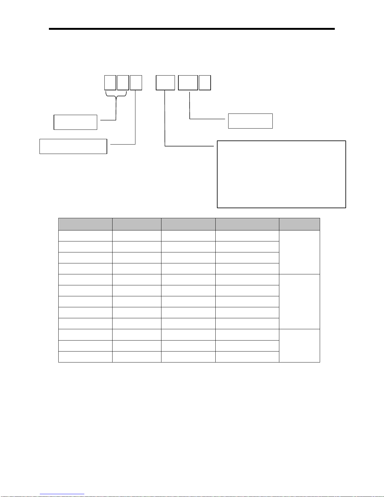
2.3 Classification and T ype of Product Name
2.3.1 Classification and type of main unit
Name of main unit is classified as follows.
Classification Name DC input Relay output Transistor output Power
Module type
Main unit
XBM-DR16S 8 point 8 point None
DC24V
XBM-DN16S 8 point None 8 point
XBM-DN32S 16 point None 16 point
Compact type
Main unit
(MK language)
XBC-DR32H 16 point 16 point None
AC110V~220V
XBC-DN32H 16 point None 16 point
XBC-DR64H 32 point 32 point None
XBC-DN64H 32 point None 32 point
XBC-DR32H/DC 16 point 16 point None
DC24V
XBC-DN32H/DC 16 point None 16 point
XBC-DR64H/DC 32 point 32 point None
XBC-DN64H/DC 32 point None 32 point
Compact type
main unit
(IEC language)
XEC-DR32H
16 point 16 point None
AC110V~220V
XEC-DN32H
16 point None 16 point
XEC-DR64H
32 point 32 point None
XEC-DN64H
32 point None 32 point
XEC-DP32H
16 point None 16 point
XEC-DP64H
32 point None 32 point
XEC-DR32H/D1
16 point 16 point None
DC 12/24V
XEC-DR64H/D1
32 point 32 point None
X B M
-
D R X X S
Relay output (R)
Sink type transistor output (N)
Source type transistor output (P)
No. of IO point
XGB PLC standard (S)
XGB PLC High-end type (H)
XGB PLC
Module type main unit (M)
Compact type main unit(C)
DC input
MK language supported (B)
IEC language supported (E)
2-4
Chapter 2 System Configuration
2.3.2 Classification and type of expansion module
Name of expansion module is classified as follows.
Name DC input Relay output Transistor output Reference
XBE-DC08A
8 point None None
XBE-RY08A/B
None 8 point None
XBE-TN08A
None None 8 point (Sink type)
XBE-TP08A
None None 8 point (Source type)
XBE-DC16A/B
16 point None None
XBE-RY16A
None 16 point None
XBE-TN16A
None None 16 point (Sink type)
XBE-TP16A
None None 16 point (Source type)
XBE-DR16A
8 point 8 point None
XBE-DC32A
32 point None None
XBE-TN32A
None None 32 point (Sink type)
XBE-TP32A
None None 32 point (Source type)
X B E
-
DC X X A
Relay output(RY)
Transistor output (TN/TP)
Digital input (DC)
Digital input+ sink type transistor output (DN)
Digital input+ source type transistor output (DP)
Digital input + relay output (DR)
No. of IO point
XGB series
I/O expansion module
2-5
Chapter 2 System Configuration
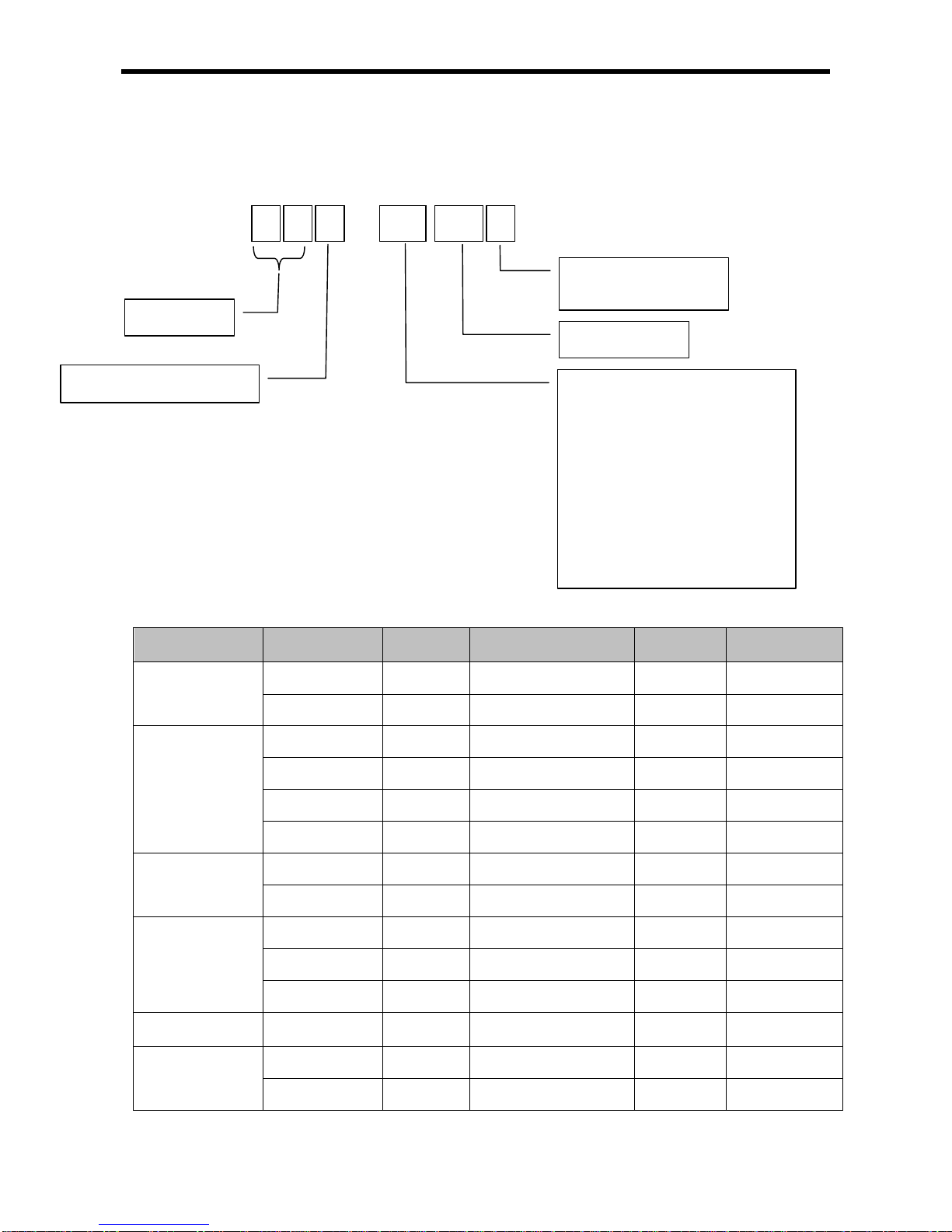
2.3.3 Classification and type of special module
Special module is classified as follows.
Classification Name
No. of
input ch.
Input type
No. of
output ch.
Output type
Analog input
XBF-AD04A 4 Voltage/Current None XBF-AD08A 8 Voltage/Current None
Analog output
XBF-DC04A None - 4 Current
XBF-DC04B None - 4 Current
XBF-DV04A None - 4 Voltage
XBF-AH04A 2 Voltage/Current 2 Voltage/Current
RTD input
XBF-RD04A 4 PT100/JPT100 None XBF-RD01A 1 PT100/JPT100 None -
TC input
XBF-TC04S 4 K, J, T, R None -
XBF-TC04RT 4 PT100/JPT100 4 Transister
XBF-TC04TT 4 K, J, T, R 4 Transister
Positioning
module
XBF-PD02A - Line Driver 2 Voltage
High Speed
Counter
XBF-HD02A 2 Line Driver
XBF-HO02A 2 Open Collector
X B F
-
AD X X A
Analog input (AD)
Analog voltage output (DC)
Analog current output (DV)
Analog combined module (AH)
RTD input (RD)
Thermocouple input (TC)
Line driver positioning module (PD)
No. of IO point
XGB series
Expansion special module
Non-insulation type (A)
Insulation type (S)
2-6

Chapter 2 System Configuration
2.3.4 Classification and type of communication module
Name of communication module is classified as follows.
Classification Name Type
Cnet Comm. Module
XBL-C21A RS-232C, 1 channel
XBL-C41A RS-422/485, 1 channel
FEnet Comm. Module XBL-EMTA Electricity, open type Ethernet
RAPIEnet Comm. Module
XBLEIMT/EIMF/EIMH
Comm. Module between PLCs, electric media,
100 Mbps industrial Ethernet supported
EtherNet Comm. Module XBL-EIPT Open EtherNet I/P
CANopen Comm. Module
XBL-CMEA CANopen Master
XBL-CSEA CANopen Slave
Pnet Comm. Module XBL-PMEC Profibus-DP
2.3.5 Classification and Type of Option Module
Name of option module is classified as follows.
Classification Name Type
Memory module XBO-M1024A Memory module : 1,024 KB
X B L - C21A
Cnet 1 channel (RS-232C): C21A
Cnet 1 channel (RS-422/485): C41A
FEnet 1 channel: EMTA
RAPIEnet 1 channel: EIMT
XGB series
Expansion communication module
X B O - M1024A
Memory module : 1,024 KB
XGB series
Option module
2-7

Chapter 2 System Configuration
2.4 System Configuration
2.4.1 Cnet I/F system
Cnet I/F System is used for communication between the main unit and external devices using RS-
232C/RS-422 (485) Int erface. The XGB ser ies has a built-in RS-232C port, R S-485 port and has also
XBL-C21A for RS-232C , XBL-C4 1A for R S-422/485. I t is pos sible to c onstruct c omm unication s ystems
on demand.
(1) 1:1 communication system
(a) 1:1 communication of an external device (computer) with main unit using a built-in port
(RS-232C/RS-485)
(b) 1:1 communication wit h main unit using a built-in RS-485 port
(In case of built-in RS-232C,it is for connecting to HMI device.)
Built-in RS-232C Connection
PADT
connection
Built-in RS-485 Connection
RS-232C / RS-485
XEC-DR32H
XEC-DR32H
XEC-DR32H
XP30-TTA
2-8

Chapter 2 System Configuration
(c) 1:1 RS-232C Communication with remote device via modem by Cnet I/F modules
(d) 1:1 communication of an external device (monito ring unit) with main unit using a built-in RS-
232C/485 port.
Modem
Modem
XBL-C21A
XEC-DR32H
XBL-C21A
XEC-DR32H
Modem
Modem
XBL-C21A
XEC-DR32H
Built-in RS-232C/485 connection
XP30-TTA
XEC-DR32H
2-9

Chapter 2 System Configuration
(2) 1:n Communication system
(a) Using RS-485 built-in function can connect between one computer and multiple main units for up
to 32 stations.
(b) Using RS-485 built-in function/expansion Cnet I/F module can be connect for up to 32 stations.
1) Refer to ‘XGB Cnet I/F user manual’ for details
Note
Max. 32 stations available
PADT connection
Built-in RS-232C connection
XEC-DN32H
Max. 32 stations available
XEC-DN32H
PADT connection
Built-in RS-232C connection
XBL-C41A
XEC-DN32H
XBL-C41A
XEC-DN32H
Max. 32 stations available
Max. 32 stations available
2-10
Chapter 2 System Configuration
Hub
Hub
Hub
Hub
Router or
Gateway
Router or
Gateway
Public line
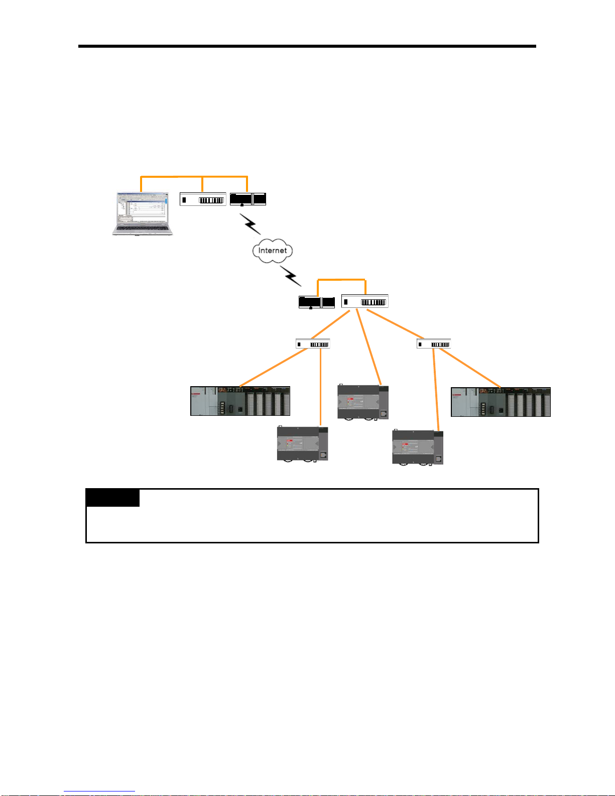
2.4.2 Ethernet system
Ethernet made b y cooperation of Xerox, Intel, DEC is standard LAN c onnection method (IEEE802.3) ,
which is network connection system using 1.5KB packet with 100Mbps transmission ability. Since
Ethernet can combine a variety of computer by network , it is called as standard specification of LAN and
diverse products. By adopting CSMA/CD m ethod, it is easy to configure the network and collect large
capacity data.
1) Refer to ‘XGB FEnet I/F user manual’ for details
Note
100Base-TX
M
HMI
HMI
H
2-11

Chapter 3 General Specifications
Chapter 3 General Specifications
3.1 General Specifications
The General specification of XGB series is as below.
No. Items Specifications Related standards
1
Ambient
temperature
0 ~ 55 °C
-
2
Storage
temperature
−25 ~ +70 °C
3
Ambient
humidity
5 ~ 95%RH (Non-condensing)
4
Storage
humidity
5 ~ 95%RH (Non-condensing)
5
Vibration
resistance
Occasional vibration
-
Frequency
Acceleration
Amplitude
times
IEC61131-2
5 ≤ f < 8.4Hz
−
3.5mm
10 times each
directions
(X, Y and Z)
8.4 ≤ f ≤ 150Hz
9.8m/s2 (1G)
−
Continuous vibration
Frequency
Acceleration
Pulse width
5 ≤ f < 8.4Hz
−
1.75mm
8.4 ≤ f ≤ 150Hz
4.9m/s2 (0.5G)
−
6
Shock
resistance
• Peak acceleration: 147 m/s
2
(15G)
• Duration: 11ms
•
Half-sine, 3 times each direction per each axis
7
Noise
resistance
Square wave
Impulse noise
AC: ±1,500 V
DC: ±900 V
LSIS standard
Electrostatic
discharge
4kV (Contact discharge)
IEC61131-2
IEC61000-4-2
Radiated
electromagnetic
field noise
80 ~ 1,000 MHz, 10V/m
IEC61131-2,
IEC61000-4-3
Fast
transient/bust
noise
Segment
Power
supply
module
Digital/analog input/output
communication interface
IEC61131-2
IEC61000-4-4
Voltage
2kV
1kV
8
Environment
Free from corrosive gasses and excessive dust
9
Altitude
Up to 2,000 ms
10
Pollution
degree
2 or less
11
Cooling
Air-cooling
1) IEC (International Electrotechnical Commission)
:
An international civil community that promotes international cooperation for standardization of
electric/ electro technology, publishes international standard and operates suitability assessment
system related to the above.
2) Pollution Degree
:
An index to indicate the pollution degree of used environment that determines the insulation
performance of the device. For example, pollution de gree 2 means the state to occur the pollution of
non-electric conducti vity generally, but the state to occ ur temporary electric conductio n according to
the formation of dew.
Notes
3-1

Chapter 4 CPU Specifications
Chapter 4 CPU Specifications
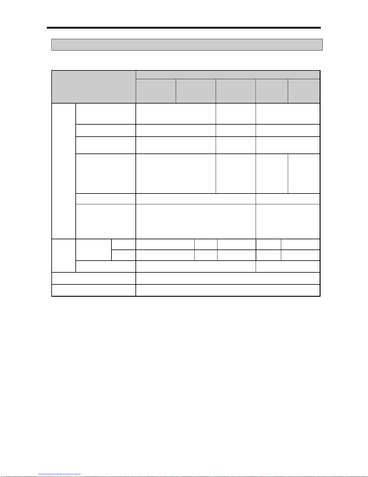
4.1 Performance Specifications
The following table shows the general specifications of the XGB main module type
Items
Specifications
Remark
XECDR32H(/D1)
XECDR64H(/D1)
XECDN32H(/DC)
XECDN64H
XECDP32H
XECDP64H
Numb
er of
instruc
tions
Operator 18
Basic function 136 + Real number operation function
Basic function block 43
Dedicated function
block
Special function dedicated function
Processing speed
Basic instruction : 0.083 ㎲/step
Program memory capacity 200KB (XEC 200KB corresponds to XGI 110KB)
Max. I/O points 352 384 352 384 352 384
Data
memory
Automatic variable
(A)
32KB (Max. 16KB retain set ting avai lable )
Input variable (I) 2 KB (%IX15.15.63)
Output variable (Q) 2 KB (%QX15.15.63)
Direct
variable
M 16KB (Max. 8KB retain setting available)
R 20KB (1block)
W 20KB Same area with R
Flag
variable
F 2KB System flag
K 8KB Built-in special flag
L 4KB High speed link flag
N 10KB P2P flag
U 1KB Analog flag
Flash area 20KB, 2 block R device used
Timer No limit to the number of point (time range: 0.001s ~ 4,294,967,295s)
20 byte automatic
variable area
occupied per r point
Counter No limit to the number of point (count range: 64 bit expression range)
Operation mode RUN, STOP, DEBUG
Restart mode Cold, Warm
Total number of program
block
128
Task
Initialization 1
Fixed period 8
External input 8 (%IX0.0.0 ~ %IX0.0.7)
Internal devi ce 8
Self diagnosis Detecting operation delay , memory error, I/O error
Data reserved in case of
power cut
Setting retain area at basic parameter
Number of max. extension
stage
10 stage
Internal consumption
current
660mA 1,040mA 260mA 330mA 300mA 380mA
Weight 600g 900g 500g 800g 500g 800g
4- 1

Chapter 4 CPU Specifications
Items Specifications Remark
Built-in function
PID control function
Controlled by instructions, Auto-
tuning, PWM output, Manual output,
Adjustable operation scan time, Anti Windup, Delta MV function, SV-
Ramp function
-
Cnet I/F function
Dedicated protocol support
MODBUS protocol support RS-232C 1 port
User defined protocol support RS-485 1 port
High-speed counter
Capacity
AC
type
1 phase: 100 kHz 4 channel, 20kHz 4 channel
2 phase: 50 kHz 2 channel, 10kHz 2 channel
D1
type
1 phase : 100 kHz 4 channel, 10 kHz 4 channel
2 phase : 50 kHz 2 channel, 5 kHz 2 channel
Counter
mode
4 different counter modes according to input pulse and
addition/subtraction method
• 1 phase pulse input: addition/subtraction counter
• 1 phase pulse input: a
ddition/subtraction counter by B
phase
• 2 phase pulse input: addition/subtraction counter
• 2 phase pulse input: addition/subtraction by
phase differences
Additional
function
• Internal/External preset function
• Latch counter function
• Comparison output function
• Revolution number per unit time function
Positioning function
Basic function
No. of control axis: 2 axes
Control method: position/speed control
Control unit: pulse
Positioning data: 80 data/axis
(operation step No. 1~80)
Operation mode: End/Keep/Continuous
Operation method: Single, Repeated operation
TR output type
support
Positioning
function
Positioning method: Absolute / Incremental
Address range: -2,147,483,648 ~ 2,147,483,647
Speed: Max. 100Kpps(setting range 1 ~ 100,000pps)
Acceleration / Deceleration method : trapezoidal method
Return to Origin
Origin detection when approximate origin turns off
Origin detection when approximate origin turns on
Origin detection by approximate origin.
JOG operation
Setting range: 1~100,00 0 ( Hi gh / Low spee d )
Additional
function
Inching operation, Speed synchronizing operation, Position
synchronizing operation, linear interpolation operation etc.
Pulse catch
10㎲ 4 points (%IX 0.0.0~%IX0.0.3), 50㎲ 4points ( %IX0.0.4
~ %IX0.0.7)
-
External interrupt
10㎲ 4points (%IX 0.0.0~%IX0.0.3), 5 0㎲ 4 points (%I X0.0.4
~ %IX0.0.7)
Input filter Select among 1,3,5,10,20,70,100 ㎳ (Adjustable)
4- 2

Chapter 4 CPU Specifications
4.2 Names of Part and Function
XGB Compact type main unit (IEC language)
No. Name Description
①
Input indicator LED
▪ Input indicator LED
②
PADT connecting
connector
▪
PADT connecting USB (USB 1.1 supported) 1 channel,
RS-232C 1 channel connector
③
Input connector and
terminal block
▪ Input connector and terminal block
④
Output connector and
terminal block
▪ Output connector and terminal block
⑤
Key switch
▪
RUN / STOP Key switch
In case of STOP mode, Remote mode changeable.
⑥
Output indicator LED ▪ Output indicator LED
⑦
Status indicator LED
It indicates CPU module’s status.
▪ PWR(Red): Power status
▪ RUN(Green): RUN status
STOP mode: Off/ RUN mode : On
▪
Error(Red): In case of error, it is flickering.
⑧
8-1
Built-in RS-232C
/ RS-485
Connecting
connector
Built-in RS-485 connecting connector
“+” , “-“ terminal connecting connector in RS-485 communication
▪ Built-in RS-232C connecting connector
“TxD” , “RxD“ , “GND” connecting connector in RS-232C
8-2
Power supply
connector
▪ AC100~240V power supply connector
⑨
Battery holder
▪ Battery (3V) holder
⑩
Mode switch
▪ Program mode and O/S download mode select switch
①
②
④
⑤
⑥
③
⑦
8-1
8-2
⑨
⑩
4- 3
Chapter 4 CPU Specifications
4.3 Power Supply Specificat ions
Describes power specification of main unit
Items
Specification
XEC-DR32H
XEC-DN32H
XEC-DP32H
XEC-DR64H
XEC-DN64H
XEC-DP64H
XEC-
DN32H/DC
XEC-
DR32H/D1
XEC-
DR64H/D1
Input
Rated voltage
(UL warranty voltage)
AC 100 ~ 240 V DC24V DC 12/24V
Input voltage range
AC85~264V(-15%, +10%)
DC19.2~28.8V
(-20%,+20%)
DC 9.5~30V
Inrush current 50APeak or less
50APeak
or less
50APeak or less
Input current
AC 220V : 0.5A or less,
AC 110V : 1A or less
0.7A or less
DC 12V :
1.4 A or
less
DC 24V :
0.7 A or
less
DC 12V :
2.1 A or
less
DC 24V :
1.0 A or
less
Efficiency
65% or more
60% or more
Permitted momentary
power failure
Less than 10 ㎳
DC 12V : less than 2
㎳
DC 24V : less than 10
㎳
Output
Rated
output
DC5V
2A
3A
2A
2A
3A
DC24V
0.4A
0.6A - -
-
Output voltage ripple
DC5V (±2%) DC4.9~5.15V
Power supply status indication
LED On when power supply is normal
Cable specification
0.75 ~ 2 mm2
* Use the power supply which has 4 A or more fuse for protecting power supply.
4- 4

Chapter 4 CPU Specifications
(1) Consumption current (DC 5V)
Type Model
Consumption current (Unit : ㎃)
Main unit
XEC-DR32H
660
XEC-DR64H
1,040
XEC-DN32H 260
XEC-DN64H
330
XEC-DP32H
300
XEC-DP64H
380
XEC-DR32H/D1 660
XEC-DR64H/D1 1,040
Expansion I/O module
XBE-DC32A 50
XBE-DC16A/B 40
XBE-DC08A 30
XBE-RY16A 440
XBE-RY08A/B 240
XBE-TN32A 80
XBE-TN16A 60
XBE-TN08A 50
XBE-TP32A 80
XBE-TP16A 60
XBE-TP08A 50
XBE-DR16A 250
Expansion special module
XBF-AD04A 120
XBF-DV04A 110
XBF-DC04A 110
XBF-DC04B 110
XBF-RD04A 100
XBF-RD01A 100
XBF-TC04S 100
XBF-PD02A 500
XBF-AH04A 120
XBF-AD08A 105
Expansion communication module
XBL-C21A 120
XBL-C41A
120
XBL-EMTA 300
XBL-EIMT 290
XBL-EIPT 290
Memory module XBO-M1024A 40
4- 5

Chapter 4 CPU Specifications
4.4 Calculation Example of Consumption Current/Voltage
Calculate the consumption current and configure the system not to exceed the output current capacity of
main unit.
(1) XGB PLC configuration example 1
Consumption of current/voltage is calculated as follows.
Type Model Unit No.
Internal 5V
consumption
current
(Unit : ㎃)
Remark
Main unit XEC-DN32H 1 260
In case contact points are On.
(Maximum consumption current)
Expansion
module
XBE-DC32A 2 50
XBE-TN32A 2 80
XBF-AD04A 1 120
All channel is used.
(Maximum consumption current)
XBF-DC04A 1 110
XBL-C21A 1 120
Consumption
current
870 ㎃
-
Consumption
voltage
4.35 W
0.87A ⅹ 5V = 4.35W
In case system is configured as above, since 5V consumption current is total 870 mA and 5V output of XGB
32 points main unit is maximum 2A, normal system configuration is available.
(2) XGB PLC configuration example 2
Type Model Unit No.
Internal 5V
consumption
current
(Unit : ㎃)
Remark
Main unit XEC-DR32H 1 660
In case all contact points are On.
(Maximum consumption current)
Expansion
module
XBE-DR16A 5 250
XBE-TN32A 2 80
XBF-AD04A 1 120
All channel is used.
(Maximum consumption current)
XBL-C21A 1 120
Consumption
current
2,310mA -
Consumption
voltage
11.55W 2.31 * 5V = 11.55W
If system is configured as above, total 5V current consumption is exceeded 2,310mA and it exceeds the 5V
output of XGB 32 points main unit. Normal system configuration is not available. Although we assume the
above example that all contact points are on, please use 64 points main unit which 5V output capacity is
higher than standard type main unit.
4- 6
Chapter 4 CPU Specifications
(3) XGB PLC configuration example 3
Type Model Unit No.
Internal 5V
consumption
current
(Unit : ㎃)
Remark
Main unit XEC-DR64H 1 1,040
In case of all contact points are
On.
(Maximum consumption current)
Expansion
module
XBE-DR16A 5 250
XBE-TN32A 2 80
XBF-AD04A 1 120
All channel is used.
(Maximum consumption current)
XBL-C21A 1 120
Consumption
current
2,690mA -
Consumption
voltage
13.45W
2.69A ⅹ 5V = 13.45W
The above system is an example using XEC-DR64H, 64 points main unit, about system (2). Unlike (2)
example, 5V output capacity of XEC-DR64H is maximum 3A, normal configuration is available.
Remark
Calculating of consum ption current is based on m aximum consum ption current. In app lication system ,
the consumption current is consumed less than above calc ulat ion.
4- 7

Chapter 4 CPU Specifications
4.5 Battery
Battery is inserted in XGB PLC compact main unit (XEC-DR32/64H, XEC-DN32/64H, XEC-DP32/64H)
4.5.1 Battery specification
Item
Specification
Voltage/Current
DC 3V / 220 mAh
Warranty period
3 years (ambient temp.)
Purpose
Program and data backup,
RTC operation in case of power failure
Specification
Manganese Dioxide lithium battery
Dimension (mm)
φ 20 X 3.2 mm
4.5.2 Notice in using
(1) Do not heat the battery or solder the polarity. ( It may cause the reduction of life.)
(2) Do not measure the voltage or short with tester. (It may cause the fire.)
(3) Do not disassemble the battery.
4.5.3 Life of battery
Life of battery depends on the power failure time and ambient temperature etc..
If battery is getting low, main unit cause the warning, ‘battery voltage low warn ing ’. The user can check it
by error LED, flag and error message of XG5000.
Since battery works properly for long time, after battery voltage low warning, so the user can take the
action after batter y voltage lo w warning occurred.
4- 8
Chapter 4 CPU Specifications
4.5.4 How to change the battery
The user should change the battery used to save the program and backup the data in case of power
failure periodically. Though the user eliminate the battery, it works for 30 minute by super capacitor.
Change the battery as fast as possible.
Sequence changing battery is as follows.
Start of battery change
Open battery cover
Pick up using battery from holder and
disassemble the connector
Insert new battery and connect to
connector with proper direction
Check the LED whether ERR LED is off
ERR LED off?
Battery malfunction
No
Yes
Complete
4- 9

Chapter 5 Program Configuration and Operation Method
Chapter 5 Program Configuration and Operation Method
5.1 Program Instruction
5.1.1 Program execution methods
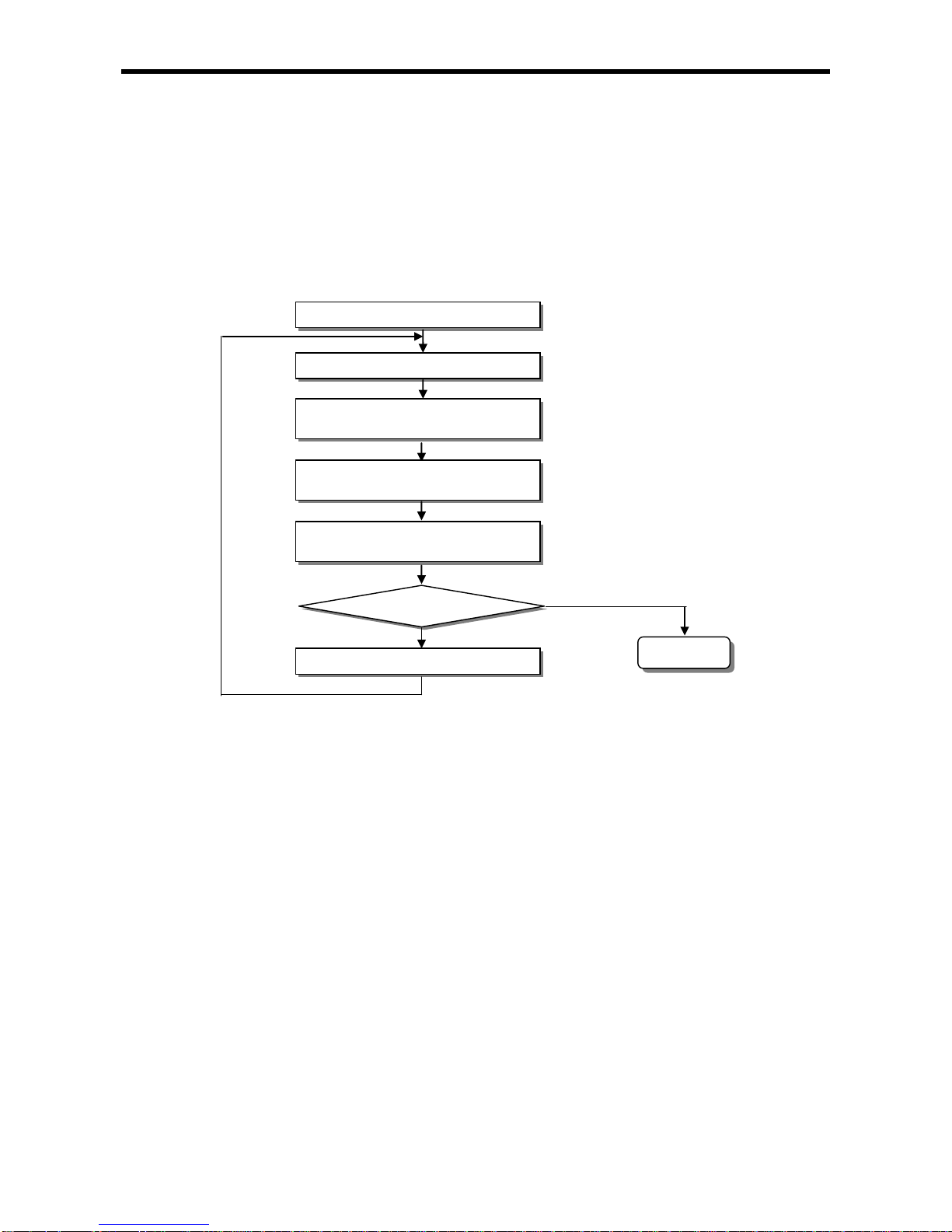
(1) Cyclic operation method (Scan)
This is a basic program pro ceeding met hod of PLC that perfo rms the oper ation repe atedly for the pr epared
program from the beginning to the last step, which is called ‘program scan’. The series of processing like
this is called ‘cyclic operation method’. The processing is divided per stage as below.
Stage Processing description
-
A s tage to start the scan processing which is executed once
when power is applied or Reset is executed, as below.
Self-diagnosis execution
Data clear
Address allocation of I/O module and type register
If initializing task is designated, Initializing program is executed.
Reads the state of input module and saves it in input image
area before starting the operation of program.
Perform s the operation in order fr om the program start to las t
step.
Performs the operation in order from the program start to last step.
A processing stage to return to the first step after CPU module
completes 1 scan processing an d the processing p erformed is as
below.
Update the current value of t imer and co unter et c.
User event, data trace service
Self-diagnosis
High speed link, P2P e-Service
Check the state of key switch for mode setting
Start
Initialization processing
Input image area refresh
Program operation processing
Program start
Program last step
Output image area refresh
END
5 - 1

Chapter 5 Program Configuration and Operation Method
(2) Interrupt operation (Cycle time, Internal device)
This is the method that stops the program operation in proceeding temporarily and carries out the
operation processing which corresponds to interrupt program immediately in case that there occurs the
status to process emergently during PLC program execution.
The signal to inform this kind of urgent status to CPU module is called ‘interrupt signal’. There is a Cycle
time signal that operates program every appointed time and external interrupt signal that operates program
by external contact point (%IX0.0.0~%IX0.0.7). Besides, there is an internal devi ce start prog ram that
starts according to the state change of device assigned in si de .
(3) Constant Scan (Fixed Period)
This is the operation method that performs the scan program every appointed time. This stands by for a
while after performing all the scan program, and starts again the program scan when it reaches to the
appointed time. The di ffe r ence fro m con stan t p r og ram i s t he up dat e o f inp ut /ou tput and t he thi ng to
perform with synchroniz ati on.
At constant operation, the scan time indicates the net program processing time where the standby time is
deducted. In case that scan time is bigger than ‘constant’, %FX92 (_CONSTANT_ER) flag shall be ‘ON’.
5.1.2 Operation processing during momentary power failure
CPU module detects the momen ta ry power fail ure when input power vol tage supp lied to power modu le is lower
than the standard. If CPU module detects the momentary power failure , it carries out the operation processing
as follows.
If momentary power failure within 10 ms is occurred, main unit (CPU) keeps the operation. But, if
momentary power failure a bove 10 ㎳, the operation is stop and t he output is Off. Restart pr ocessing
like at power input shall be performed.
(1) Momentary power failure within 10 ms
(2) Momentary power failure exceeding 10 ms
Remark
1) Momentary power failure?
This means the state that the voltage of supply power at power condition designated by PLC is
lowered as it exceeds the allowable variable range and the short time (some ms ~ some dozens ms)
interruption is called ‘momentary power failure’ ).
Restart processing like at power input shall
be performed.
Input power
Input power
Momentary power failure exceeding 10 ms
Momentary power failure within 10 ms
(1) When momentar y po wer failure occurs, PLC holds
its output status and stop operation.
(2) If momentary power failure is canceled, operation
continues.
(3) Output voltage of power module keeps value is
specification.
(4) Though momentary power failure occurs and
operation stops, timer measurement and timer
measurement for interrupt is conducted normally.
5 - 2

Chapter 5 Program Configuration and Operation Method
5.1.3 Scan time
The processing time from program step 0 to the next step 0 is called ‘Scan Time’.
(1) Scan time calculation expression
Scan time is the sum of the processing time of scan program and interrupt program prepared by the user
and PLC internal time, and i s disting uished by the follow ing fo rmula.
(a) Scan time = Scan program processing time + Interrupt program processing time + PLC internal
processing time
Scan program processing time = processing time of user program not saved as interrupt program
Interrupt program processing time = Sum of interrupt program proceeding time processed during 1 scan
PLC internal processing time = Self-diagnosis time + I/O refresh time + Internal data processing time
+ Communication service processing time
(b) Scan time depends on whether to execute interrupt program and communication processing.
(2) Scan time monitor
(a) Scan time can be monitored 『Online』-『PLC Information』-『Performance』.
(b) Scan time is save in special relay (F) area as follows.
%FW50: max. value of scan time (unit: 0.1 ms)
%FW51: min. value of scan time (unit: 0.1 ms)
%FW52: current value of scan time (unit: 0.1 ms)
5- 3

Chapter 5 Program Configuration and Operation Method
5.1.4 Scan Watchdog timer
WDT (Watchdog Timer) is the function to detect the program congestion by the error of hardware and software of
PLC CPU module.
(1) WDT is the timer used to detect the operation delay by user program error. The detection time of WDT is
set in Basic parameter of XG5000.
(2) If WDT detects the excess of detection setting time while watching the elapsed time of scan
during operation, it stops th e oper ation of PLC im m ediately an d k eeps or cle ars t he outp ut ac cordi ng
to parameter setting
(3) If the excess of Scan Watchdog Time is expected in the program processing of specific part while
performing the user program (FOR ~ NEXT instruction, CALL instruction), clear the timer by using
‘WDT_RST’ Function
‘WDT_RST’ Function initializes the elapsed time of Scan Watchdog Timer and starts the time measurement
from 0 again.
(For further information of WDT_RST Function, please refer to Instruction.)
(4) To clear the erro r state o f watchdog , we can use the fol lowing method : powe r re-supply, PLC reset,
mode conversion to STOP mode.
Remark
1) The setting range of Watchdog Timer is 10 ~ 1000ms (Unit: 1ms).
WDT_RST instruction
execution
0 1 2 3 ….. …8 9
SCAN END
WDT Reset
0 1 2 …
WDT
count(ms)
0 1 2 … …6 7
SCAN END
0 1 2 …
5- 4
Chapter 5 Program Configuration and Operation Method
5.2 Program Execution
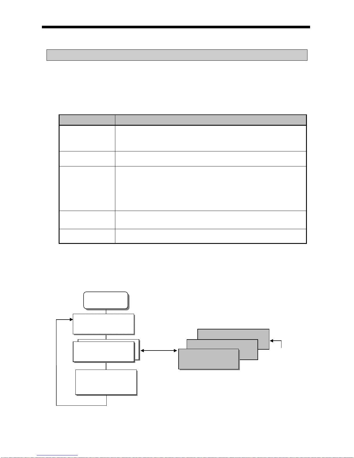
5.2.1 Configuration of program
All functional elements need to execute a certain control process are called as a ‘program’. Program is stored in
the built-i n RAM mounte d on a CPU module or flash memory of a exter nal memory module. The following tabl e
shows the classification of the program.
Program type Description
Initializing program
• It will be executed till the specific Flag ‘INIT_DONE’ is On. And while the
initialization task is executed, several of initializing program is
programmed. (If INIT_DONE instruction is executed, scan program is
executed.)
Scan program
• The scan program is executed regularly in every scan.
Cycle time interrupt
program
• The pr ogram is perf ormed ac cordi ng to t he fixe d tim e interv al in c ase th at the
required processing time condition is as below.
In case that the faster processing than 1 scan average processing time is
required
In c ase that t he longer t ime interv al than 1 sc an averag e process ing time is
required
In case that program is processed with the appointed time interval
External interrupt
program
• The exter nal interrupt program is perform ed process on external interrupt
signal.
Subroutine
program
•
Only when some condition is satisfied.(in case that input condition of CALL
instruction is On)
5.2.2 Program execution methods
Here describes the program proceeding method that is executed when the power is applied o r key swi t ch i s ‘ RUN’.
The program performs the operation processing according to the configuration as below.
Start processing
Scan program
END processing
Subroutine program
External interrupt program
Cycle time program
Only when some
condition is satisfied.
Initializing program
It executes up to execution of INIT_DONE instruction when initializing program is designated.
5- 5

Chapter 5 Program Configuration and Operation Method
(1) Scan program
(a) Function
• This program performs the operation repeatedly from 0 step to last step in order prepared by the program
to process the signal tha t is repeated ly regularly every scan.
• In case that the execution condition of interrupt by task interrupt or external input while executing program
is established, stop the current program in execution and perform the related interrupt program.
(2) Interrupt program
(a) Function
• This program stops the operation of scan program and then processes the related function in prior to
process the internal/external signal occurred periodically/non-periodically.
(b) Type
• Task p rogr a m is di v ide d a s bel ow .
- Cycle time task program: available to use up to 8.
- Internal device ta sk program: available to u se up t o 8.
- I/O (External contact task program): available to use up to 8. (%IX0.0.0~%IX0.0.7)
• Cycle time task program
- Performs the program according to the fixed time internal.
• Internal devi ce task prog ram
- Performs the corresponding program when the start condition of internal device occurs.
- The start cond ition de tection of device shall be performed after processing of scan program.
• I/O (External contact task program)
- Performs the program according to the input external signal (%IX0.0.0~%IX0.0.7).
Remark
(1) Write the interrupt program as s hortl y as poss i ble . I n c as e same interrupt occurs repeatedly
before completion of interrupt, program is not executed and O/S watch dog error may occur.
(2) Though interrupt whic h has lower priority occurs man y times during execution of interrupt
which has higher priority, interrupt which has lower priority occurs only one time.
5- 6
Chapter 5 Program Configuration and Operation Method
5.2.3 Interrupt
For your understanding of Interrupt function, here describes program setting method of XG5000 which is an XGB
programming S/W. Example of interrupt setting is as shown bellows.
• Interrup t setting
Interrupt source Interrupt name priority Task No. Program
Initializing Interrupt 0_ - - Cycle time 1 Interrupt 1_cycle time 2 0 Cycle time 1
External Interrupt 2_external 2 8 External
Internal devi ce Interrupt 3_internal 3 16 Internal
Cycle time 2 Interrupt 4_cycle time 3 1 Cycle time 2
Remark
• In case that several tasks to be executed are waiting, execute from the highest Task Program in
priority. When the same priority tasks are waiting, execute from the order occurred.
• While interrup t executing, if the h ig h est i nt er rupt is occurre d, th e h ig h est interrupt is exec u ted earliest of
all.
• When power On, All interrupts are in the state ‘Enable’.
• Internal device interrupt i s e xe cut ed after END instruction.
Initializing
(Before INIT_DONE instruction)
Cycle time 1 execution
Interrupt 1_Cycle time
occur
Cycle time 1/
external occur
simultaneously
Cycle time 1 execution
External I/O execution
Internal device
Interrupt occur
Internal device interrupt
execution
Cycle time 1
execution
Timed-driven 1
execution
Cycle time 2
occur
Cycle time 2 execution
END
Scan program
5- 7

Chapter 5 Program Configuration and Operation Method
(1) How to prepare interrupt program
Generate the task in the project window of XG5000 as below and add the program to be performed by each
task. For further information, please refer to XG5000 user’s manual.
(It can be additi onal when XG5000 is not connec ted with PLC .)
(a) Click right button of mouse on project name and click 『Add item』-『Task』.
(b) The screen of Task setti ng is show n. Cli ck 『Initialization』 in Execution condition and make a Task name.
5- 8

Chapter 5 Program Configuration and Operation Method
(c) Click right button of mouse at registered task and select『Add Item』-『Program』.
(d) Make initia lizing program. In initializing program , INIT_DONE instruction must be m ade. If not, Scan
program is not executed.
5- 9

Chapter 5 Program Configuration and Operation Method
(2) How to prepare Cycle interrupt program
Generate the task in the project window of XG5000 as below and add the program to be performed by each
task. For further information, please refer to XG5000 user’s manual.
(It can be additional whe n XG5000 is not connected with PLC)
(a) Click right button of mouse at registered task and select『Add Item』-『Task』.
• It shows setting screen of Task.
5- 10

Chapter 5 Program Configuration and Operation Method
(b) Task type
Classification Description Remark
Task name Make Task name.
Character, number
available
Priority Set the priority of task. (2~7)
“2” is the highest
priority number.
Task number
Set the Task number.
• Cycle time task (0 ~ 7): 8
• External I/O task (8 ~ 15): 8
• Internal device task (16 ~ 23): 8
-
Execution
condition
Initialization Set the initial program when running the project.
Till the execution of
INIT_DONE
instruction
Cycle time Set the cyclic interrupt.
0~4294967295㎳
available
I/O Set the external I/O.
%IX0.0.0~%IX0.0.7
available
Internal
device
Set the internal device to interrupt execution.
• Bit: Among Rising, Falling, Transition, On, Off
• Word: Among >,>=,<,<=
-
(c) Click right button of mouse at registered task and select『Add Item』-『Program』.
5- 11
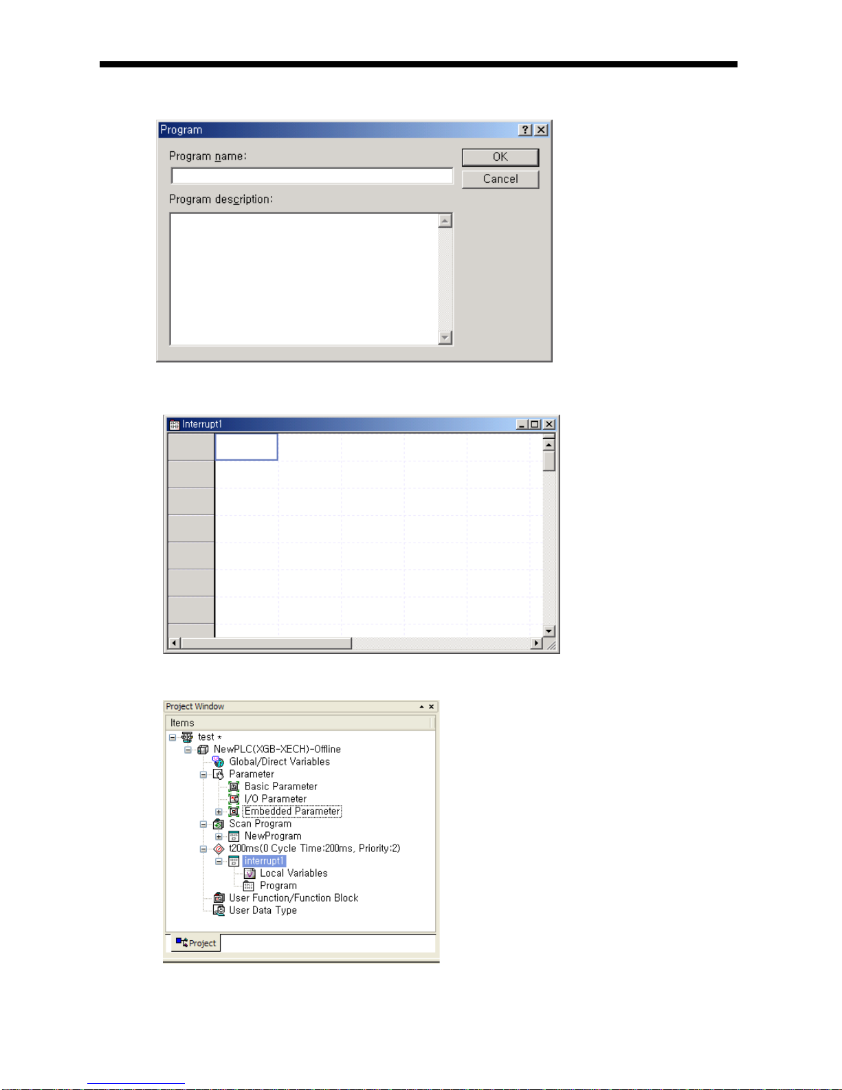
Chapter 5 Program Configuration and Operation Method
(d) Register the Program name and Program description.
(e) It is displayed the p rog ram window to write ta sk program.
(f) It is displayed the setting in proj ec t windo w.
5- 12

Chapter 5 Program Configuration and Operation Method
(3) Task type
Task type and function i s as follows.
Type
Spec.
Cycle time task
(Interval task)
I/O task
(Interrupt task)
Internal device task
(Single task)
Max. Task
number
8
8 8
Start condition
Cyclic
(setting up to max.
4,294,967.295 sec. by
1ms unit)
Rising or falling edge of
main unit’s contact
(%IX0.0.0~%IX0.0.7)
Internal device
execution condition
Detection and
execution
Cyclic execution per
setting time
Immediate execution at
the edge of main unit’s
contact
(%IX0.0.0~%IX0.0.7)
Retrieve the condition
and execute after
completing Scan
Program
Detection delay
time
Max. 1 ms delay Max. 0.05 ms delay
Delay as much as max.
scan time
Execution
priority
2~7 level setting
(2 level is highest in
priority)
2~7 level setting
(2 level is highest in
priority)
2~7 level setting
(2 level is highest in
priority)
Task no.
Within 0~7 range
without user
duplication
With 8~15 range without
user duplication
Within 16~23 range
without user duplication
(4) Processing methods of task program
Here describes common processing method and notices for Task program.
(a) Feature of task program
1) Task Program is executed only when execution condition occurs without every scan repeat processing.
When preparing Task Program, please consider this point.
2) For example, if a timer and counter were used in cyclic task program of 10 second cycle, this timer
occurs the tolerance of max. 10 seconds and the counter and the timer and as the counter checks the
input status of counter per 10 seconds, the input changed within 10 se conds is not counted up.
(b) Execution priority
1) In case that several tasks to be executed are waiting, execute from the highest Task Program in priority.
When the same priority tasks are waiting, execute from the order occurred.
2) In case Cycle time task and external I/O task is occurred concurrently, execute from the highest task
program. (In sequence of XG5000 setting)
3) The task program priority should be set considering the program features, importance and the
emergency when the execution requested.
(c) P rocessing delay time
There are some causes for Task Program processing delay as below. Please consider this when task
setting or program preparation.
1) Task detection delay (Refer to detailed description of each task.)
2) Program proceeding delay caused by Priority Task Program proceeding
(d) Relationship of initialize, Scan Program and Task Program
1) ser identification task does not start while performing Initialization Task Program.
2) As Scan Program is set as lowest priority, if task occurs, stop Scan Program and process Task Program
in advance. Accordingly, if task occurs frequently during 1 scan or concentrates intermittently, scan time
may extend abnormally. Cares should be taken in case of task condition set ting.
5- 13

Chapter 5 Program Configuration and Operation Method
(e) Protection of Program in execution from Task Program
1) In case that the continuity of program execution is interrupted by high priority Task Program during
program execution, it is available to prohibit the execution of Task Program partially for the part in
problem. In this case, it is available to perform the program protection by ‘ DI (Task Program Sta rt
Disabled) and ‘EI (Task Program Start Enabled)’ Function
2) Insert ‘DI’ Function in the sta rt po si ti on of t he pa rt re quiri ng the prote ction and inse rt ‘EI’ Function in the
position to release. Initialization Task is not influenced by ‘DI’, ‘EI’ Function.
3) If interrupt i s occurred while ‘CALLP’ instruction executing, interrupt program is executed after ‘CALLP’
instruction execution.
(5) Cyclic task program processing method
Here describes the processing method in case that task (start condition) of Task program is set as Cycle
time.
(a) Items to be set in Task
Set the execution cycle and priority which are the start condition o f Task prog ram to exe cution. Check th e
task no. to manage the task.
(b) Cyclic task processing
Performance the corresponding cyclic task program per setting time interval (execution cycle).
(c) Notice in using cyclic task program
1) When cyclic task program is in execution currently or waiting for execution, if the demand to execute the
same task program occurs, the new occurred task shall be disregarded.
2) Timer that makes a demand to execute cyclic task program only while operation mode is Run mode,
shall be added. The shutdow n time shal l be all di srega rded.
5- 14

Chapter 5 Program Configuration and Operation Method
3) When setting the execution cycle of cyclic task program, consider the possibility that the demand to
execute several cyclic task program at the same time occurs.
If 4 cyclic task programs that the cycle is 2sec, 4sec, 10sec and 20sec are used, 4 demands of
execution per 20 seconds shall be occurred at the same time and scan time may extend
instantaneously.
(6) I/O task program processing
It described the I/O task program processing. (%IX0.0.0~%IX0.0.7)
5- 15
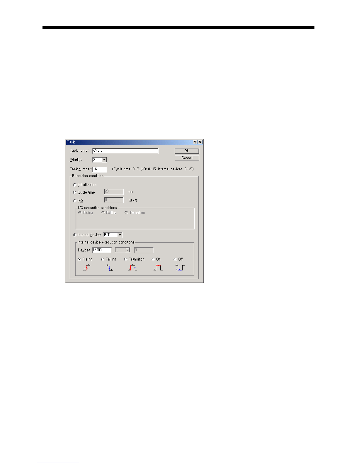
Chapter 5 Program Configuration and Operation Method
(a) Items to be set in Task
Set the execution condition and priority to the task being executed. Check the task no. to manage the
task.
(b) I/O task processing
If inte rrupt signa l from external signal (I/O) is occurred on main unit (%IX0.0.0~%IX0.0.7), ta sk program is
executed by external (I/O) signal.
(c) Precaution in using I/O task program
1) If task program which is executed by inte rr upt sig nal is on execution o r standby status , new tas k
program which is requested by identical I/O is ignored.
2) Only operation mode is Run mode, execution request of task program is recognized. Namely, execution
request of task program is ignored when operation mode is Stop mode.
(7) Internal device task program processing
Here describes the processing method of international device task program which extended the tas k (star t
condition) of task program from contact point to device as execution range.
(a) Items to be set in Task
Set the execution condition and priority to the task being executed. Check the task no. for task
management.
(b) Internal device task processing
After completing the scan program execution in CPU module, if the condition that becomes the start
condition of internal device task program is met, according to the priority, it shall be executed.
5- 16

Chapter 5 Program Configuration and Operation Method
(c) Precautions in using internal device task program
1) Accordingly, even if the executi on cond ition o f internal device task program occurs in Scan Program
or Task Program (Cycle time, I/O), it shall not be e xecuted i mmedi at ely but executed at the time of
completion of Scan Program.
2) If the demand to execute Internal Device Task Program occurs, the execution condition shall be
examined at the time of completion of Scan Program. Accordingly, if the execution condition of Internal
Device Task occurs by Scan Program or Task Program (Cycle time) during ‘1 scan’ and disappears, the
task shall not be executed as it is not possible to detect the execution at the time of examination of
execution condition.
(8) Verification of task program
(a) Is the task setting proper?
If task occurs frequently more than needed or several tasks occur in one scan at the same time, scan time
may lengthen or be irregular. In case not possible to change the task setting, verify max. scan time.
(b) Is the priority of task arranged well?
The low priority task program shall be delayed by the high priority task program, which results in disabling
the processing within the correct time and even task collision may occur as next task occurs in the state
that the execution of previous task is delayed. Consider the emergency of task and execution time etc
when setting the priority.
(c) Is the Task Program written in shortest?
If the execution time of Task Program is longer, scan time may lengthen or be irregular. Even it may cause
the collision of task program. Write the execution time as short as possible. (Especially, when writing the
cyclic task program, write the execution time so that the task program can be executed within 10% cycle
of the shortest task among several tasks.)
(d) Is program protection for the high priority task needed during program execution?
If other task is inserted during task program execution, complete the task in execution and operate the
standby tasks in th e o rder o f hi gh p riori ty . I n ca se th at it i s n ot al l ow ed to i nse rt ot he r task i n S can
Program, prevent the insert partially by using ‘DI’ and ‘EI’ application instruction. The problem may occur
while processing the global variables used commonly with other program or special or communication
module.
(9) Program configuration and processing example
If task and program are registered as below.
Interrupt type Interrupt name Priority Task No. Program
Cycle time 10 ㎳_cycle time 3 0 Program 1
Internal devi ce Internal d evi ce_%MX0 5 16 Program 2
I/O I/O_%IX0.0.0 2 8 Program 3
1) Scan program name: “ Scan Program”
2) Execution time respective program: Scan program = 17 ㎳, Program 1 = 2 ㎳, Program 2= 7 ㎳,
Program 3 = 2 ㎳
5- 17

Chapter 5 Program Configuration and Operation Method
Process per time
Time (㎳)
Process
0 Scan started and scan program started to execute.
0~6 Scan program is executed.
6~8
Scan program is stop because execut ion external I/O (P000) is reques ted. And progr am
3 is executed. Request of execution at 7[m s] is ignored because program 3 has been
executing.
8~10 Program 3 is finished and Scan program is continued.
10~12
Scan program is stop b y reques t of ‘10㎳_Cycl e ti me ’ interrupt signal a nd execut e program
1.
12~20 Program 1 is finished and Scan program is continued.
20
Request of ‘Cycle time’ interrupt signal and ‘External I/O (P000)’ signal is occurred
concurrently but priorit y of ‘External I/O’ signal is higher than ‘C ycle tim e’ interrupt signal
so program 3 is executed and program 1 is standby.
20~22 Program 3 is finished and Scan program is continued.
22~24 After program 3 is completed, program 1 (the program of ‘10ms_Cycle time’ is executed.
24~25 P1 execution completed and the stopped scan program execution finished
25
At the finished point of scan program, check the request of Internal device ‘M000’
execution and execute program 2.
25~30 Program P2 is executed.
30~32
When ‘10㎳_Cycle time’ interrupt signal is occurred, the priority of that is high er t ha n Int ernal
device ‘M000’ though program 2 is stopped and program 1 is executed.
32~34 P1 executed completed and the stopped P2 execution finished
34 New scan starts (Start scan program execution)
PO executed
P1 executed
10ms_Cycle time
Program 2
Internal device_%MX0
Program 3
External I/O_%IX0.0.0
Time
0 6 7 8 10
12
20
22
24
25
30
32
34
Scan started
(Initial operation started)
Scan program stopped
New scan started
5- 18

Chapter 5 Program Configuration and Operation Method
5.3 Operation Mode
For operation mode of CPU module, there are 3 types such as RUN mode, STOP mode and DEBUG mode..
Here describes the operation processing of each operation mode.
5.3.1 RUN mode
This is the mode to executed program operation normally.
(1) Processing at mode change
At the beginning, execute initialization of data area and examine the effectiveness of program and judge the
possibility of execution.
(2) Operation processing contents
Execute I/O refresh and program operation.
(a) Detects the start condition of Interrupt Program and executes Interrupt Program.
(b) Examines the normal operation or missing of built-in module.
(c) Communication service and other internal processing.
RUN mode first scan start
Initialize data area
Examine Program effectiveness and judge the
possibility of execution
Execute input refresh
Program execute, Interrupt Program ex ecute
Communication service and internal processing
Execute output refresh
Operation
mode change
RUN mode keep
Change to other mode
Operation by changed operation
mode
Examine the normal operation or missing of
built-in module
5- 19
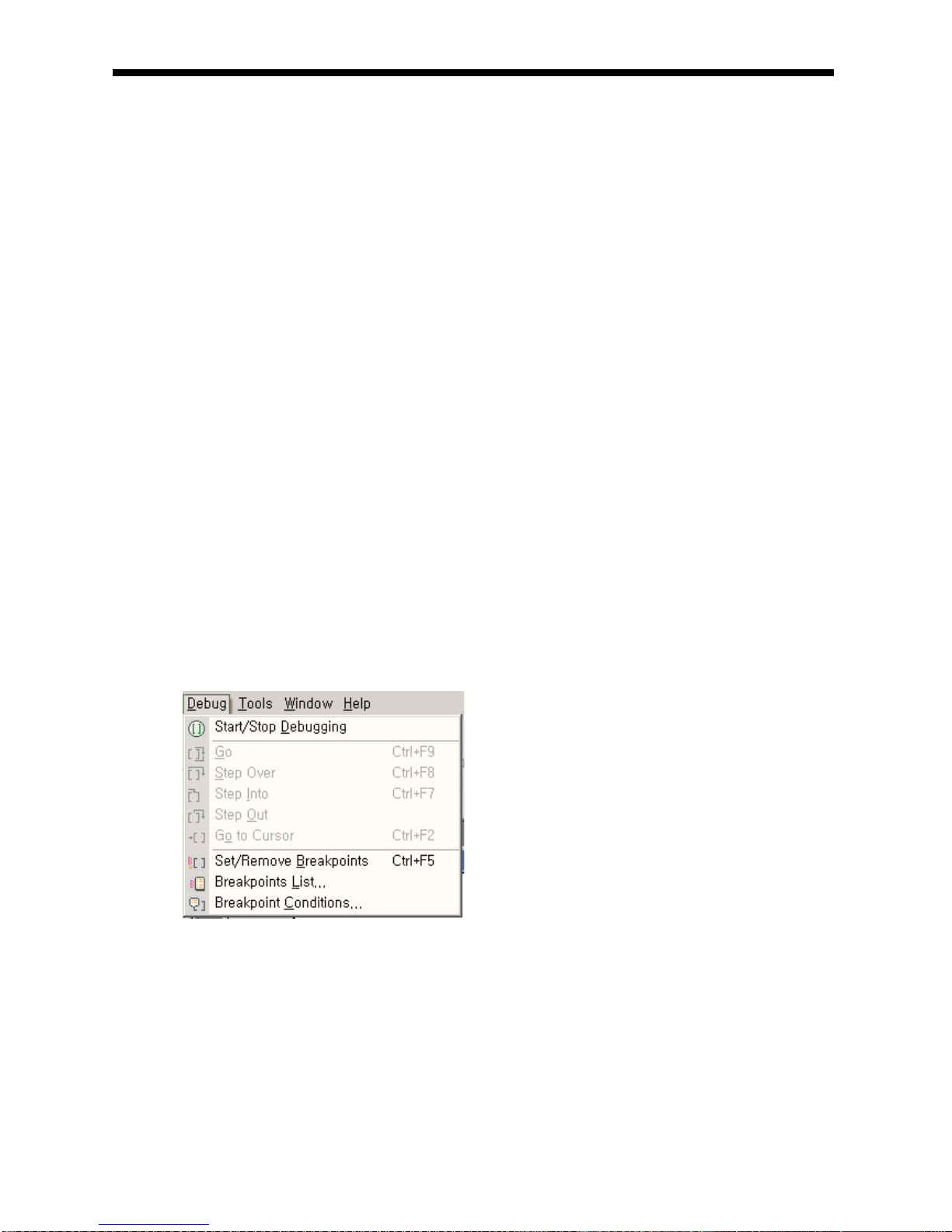
Chapter 5 Program Configuration and Operation Method
5.3.2 STOP mode
This is the mode in stop state without Program operation. It is available to transmit the program through XG5000
only in Remote STOP mode.
(1) Processing at Mode Change
Clear the output image area and execute output refresh.
(2) Operation Processing Contents
(a) Executes I/O refresh.
(b) Examines the normal operation or missing of built-in module.
(c) Communication service or other internal processing.
5.3.3 DEBUG mode
This is the mode to detect Program error or trace the operation process and the conversion to this mode is
available only in STOP mode. This is the mode to check the program execution state and the contents of each
data and verify the program.
(1) Processing at mode change
(a) Initializes the data area at the beginning o f mode change.
(b) Clears the output i mage a rea and e xe cute i npu t r e fresh.
(2) Operation processing contents
(a) Executes I/O refresh.
(b) Debug ope ration acc ording to s ettin g state.
(c) Afte r fini shi ng D ebu g opera tio n by the end of Program, execute output refresh.
(d) Examine the normal operation or missing of built-in module.
(e) Executes communication service or other service.
(3) Debug operati on
It describes debug mode.
5- 20
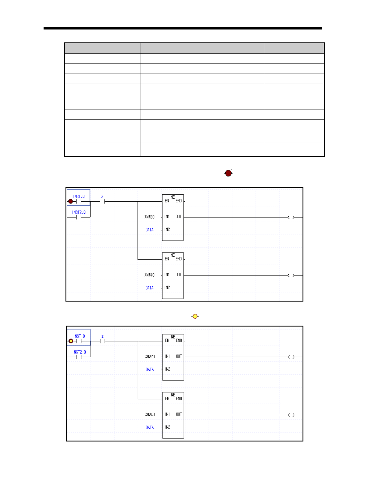
Chapter 5 Program Configuration and Operation Method
Item Description Remark
Start/Stop Debugging Change the debug ↔ stop mode
Go It starts debug operati on.
Step Over It operates by 1 step.
Step Into It starts the subroutine program.
Other
operation is
identical to
Step Over.
Step Out It finished the subroutine program.
Go to Cursor It operates to current cursor position.
Set/Remove
Breakpoints
Set/Removes current cursor position to
break points.
Breakpoints Lis t It displays list of breakpoints.
Breakpoint
Conditions
It specifies device value and number of
scan.
(a) Set/Remove Breakpoints
▪ Sets breakpoint at current cursor position. After breakpoint setting, (breakpoint setting indicator) is
displayed.
(b) Go
▪ Run the program to breakpoint. At break-pointer (stop indicator) is displayed.
error 1
error 2
error1
error2
5- 21

Chapter 5 Program Configuration and Operation Method
(c) Step Over
▪ Run the program to next step. At break point, Step over in di ca tor is displayed.
(d) Breakpoint List
▪ It displ ay s c u rrent B re a kpoint Li s t. I t supp o rt s Sele c t A ll , Re set A ll, Goto, R e move, R e move All.
error 1
error 2
5- 22
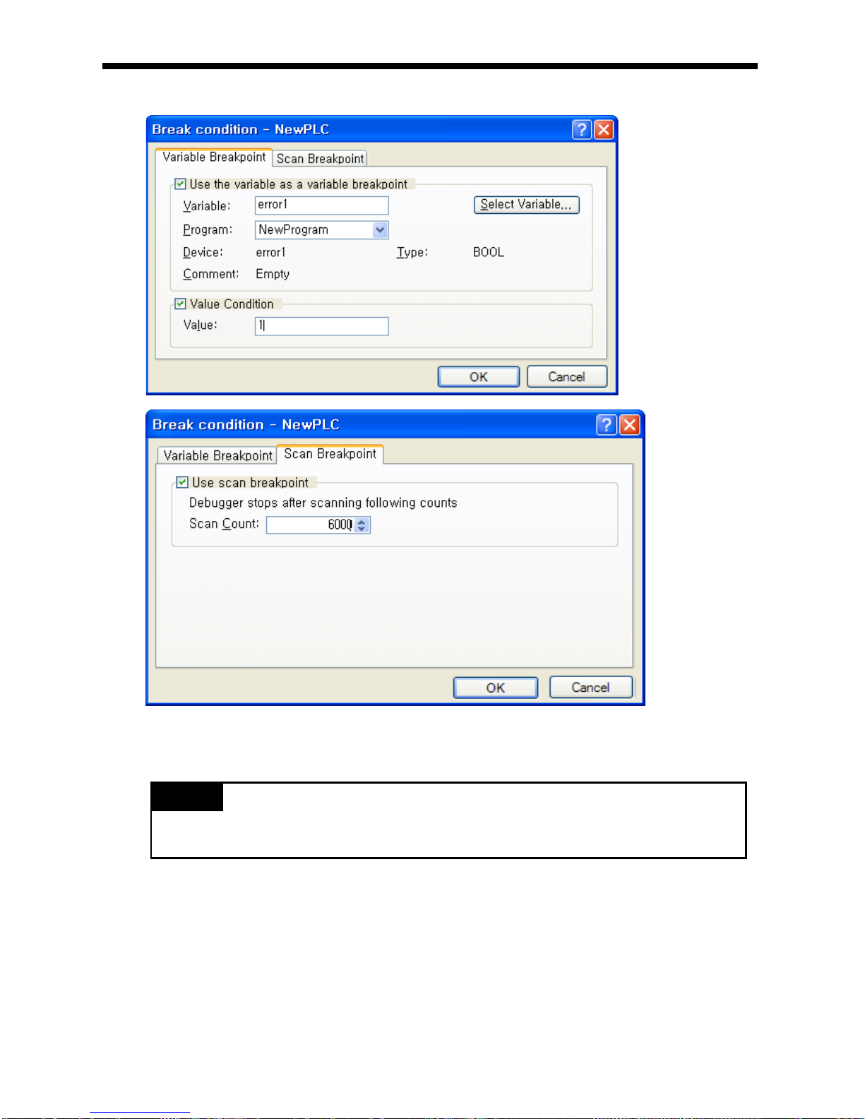
Chapter 5 Program Configuration and Operation Method
(e) B reak condit ion
▪ It sets D ev i ce B rea k an d S can B r ea k.
Remark
1) Refer to XG5000 Us e rs Manual ‘Chapter 12 Debuggi ng’ for detailed in formati on.
5- 23

Chapter 5 Program Configuration and Operation Method
5.3.4 Change operation mode
(1) Operation Mode Change Method
The method to change operation mode are as follows.
(a) By mode key of CPU module
(b) By connecting the programming tool (XG5000) to communication port of CPU
(c) By changing the operation mode of other CPU module connected to network by XG5000 connected to
communication port of CPU.
(d) By using XG5000, HMI, computer link module connected to network
(e) By ‘STOP‘ instruction during program execution
(2) Type of operation mode
The operation mode setting is as follows.
Operation mode switch XG5000 command Operation mode
RUN - Run
STOP
RUN Remote Run
STOP Remote Stop
Debug Debug Run
Mode change P revi ous ope ration mode
RUN -> STOP - Stop
(a) Remote mode co nver sion is avail abl e only in the s tate of ‘Remote Enabled: On’, ‘Mode switch: Stop’.
In case of changing the Remote ‘RUN’ mode to ‘STOP’ by switch, ope rate the switch as foll ows.
(STOP) RUN STOP .
Warning
In case of changing Remote RUN mode to RUN mode by switch, PLC operation continues the
operation withou t i nt err up tion.
It is available to modify during RUN in RUN mod e by switc h but th e mode cha nge oper ation b y
XG5000 is limited. This should be set only in case that remote mode change is not allowed.
5- 24

Chapter 5 Program Configuration and Operation Method
5.4 Memory
There are two types of memory in CPU module that the user can use. One is Program Memory that saves the
user program written by the user to build the system, and the other is Data Memory that provides the device area
to save the data during operation.
5.4.1 Program memory
Contents and size of program memory are as follows.
Item
Size
Program memory entire area
1.76 MB
System area:
System program area
Backup area
512 KB
Parameter area:
Basic parameter area
I/O parameter area
High speed link parameter area
P2P parameter area
Interrupt setting inf ormation area
Reserved area
48 KB
Execution program area:
Scan program area
Task program area
200 KB
Program reserved area
Scan program backup area
Task program area
Upload area
User defined function/function block area
Variable initialization information area
Reserved variable assignment information area
Reserved area
1 MB
5- 25

Chapter 5 Program Configuration and Operation Method
5.4.2 Data memory
Contents and size of data memory are as follows.
Item
Size
Data memory entire area
256 KB
System area :
I/O information table
Forced I/O table
Reserved area
143 KB
Flag area
System flag (F)
2 KB
Analog image flag (U)
1 KB
Internal special flag (K)
8 KB
High speed link (L)
4 KB
P2P flag (N)
10 KB
Input image area (%I)
2 KB
Output image area (%Q)
2 KB
R area (%R)
20 KB
Direct variable area (%M)
16 KB
Symbolic variable area (maximum)
32 KB
Stack area
16 KB
5.4.3 Data retain area setting
In case you want to k e ep th e da ta necessary for operation and the data m ad e dur in g op eration when PL C
stops and rest arts, Default( automatic) Vari able Retain is us ed and some are a of M area can be s et as
Retain area through parameter setting
The following is chara cteri stic table about the devi ce availa ble fo r Retain setting
Device
Retain
setting
Characteristic
Default
O
As for automatic variable area, Retain setting is available
M
O
As for internal c on tact p oin t ar ea, Ret ai n set tin g i s av ai labl e at pa ra mete r
K
X
In case of power failure, contact point is kept
F
X
System flag area
U
X
Analog data register (Ret ain i s no t avai l able )
L X
High speed link/P2P service sta tus contact point of c ommunication modul e
(Retain is available )
N
X
P2P service address area o f communi cation module (Retai n is av ailable )
R
X
Flash memory dedicated area (Retain is available)
Remark
1) K, L, N, R devices are retained basically.
2) K, L, N devices can be deleted through “Clear PLC” of XG5000 online menu.
3) For more detail, refer to “Online” of XG5000 user manual.
5- 26

Chapter 5 Program Configuration and Operation Method
1) Initialization of data according to restart mode
There are three variable related with restart mode (Default, initialization and retain variable). Initialization
method about each variable in case of executing restart mode is as follows.
2) Operation of data retain area
Method on delet ing t he Retain da ta i s as foll ow s.
- RESET through XG5000 (Overall Reset)
- Execute “Clear PLC” through XG5000 at STOP mode
- Writing by program (Initialization program recommended)
- Writing ‘0’ FILL etc at XG5000 monitor mode
For holding of retain area data or reset (clear) operation according to PLC operation, refer to the following
table.
Classification Retain M area Retain R area
Reset
Hold previous value Hold previous value Hold previous value
Overall reset
Initialized as ‘0’ Initialized as ‘0’ Hold previous value
STOP→RUN
Hold previous value
Hold previous value
Hold previous value
Remark
1) Terms on three types of variable are as follows.
(1) Default variable : variable not set as INIT or Retain variable
(2) INIT variable : initial value is set
(3) Retain variable : Holds previous value
3) Initialization of data
If PLC becom es ‘Cleat Mem ory’ status, mem ory of all dev ices are delete d as ‘0’. W hen you want to specif y
initial value , use initialization task . At CPU module, there are two t ypes of built-in memory. One is pr ogram
memory to save program made by user, for user to s tructure sys tem, Another is dat a memory provid i ng de v ic e
area saving data during operation.
Mode
Variable assignment
COLD WARM
Default Initialized as ‘0’ Initialized as ‘0’
Retain Initialized as ‘0’ Hold p rev iou s v al ue
Initialization
Initialized as user de fined val ue
Initialized as user de fined val ue
Retain & Initialization I nitial ized a s user define d valu e Hold previous val ue
5- 27

Chapter 5 Program Configuration and Operation Method
5.4.4 Data Memory Map
User program area
Parameter area
User program area
(200 KB)
Data area
Automatic variable
(32 KB)
Z127
Z000
Input variable
(2 KB)
“I”
%IX0.0.0
%IX15.15.63
Output variable
(2 KB)
“Q”
%QX0.0.0
%QX15.15.63
Direct variable M area
(16 KB)
“M”
%MW8188
%MW0
Direct variable R area
(20 KB)
“R”
%RW10236
%RW0
Direct variable W area
(20 KB)
“W”
%WW10236
%WW0
Direct variable F area
(2 KB)
“F”
%FW1020
%FW0
Direct variable K area
(8 KB)
“K”
%KW4092
%KW0
Direct variable L area
(4 KB)
“L”
%LW2044
%LW0
Direct variable N area
(10 KB)
“N”
%NW5116
%NW0
Direct variable U area
(1 KB)
“U”
%UW0.15.31
%UW0.0.0
5- 28

Chapter 6 CPU Functions
Chapter 6 CPU Functions
6.1 Type Setting
It describes settin g of XGB PLC type.
PLC
Series
CPU type Language Description Reference
XGB
XGB-DR16C3
MK
language
Dedicated product Module type
XGB-XBMS
MK
language
“S” type : XBM-DN16/32S , XBMDR16S
Module type
XGB-XBCH
MK
language
“H” type : XBC-DR32/64H , XBCDN32/64H
Compact
type
XGB-XECH
IEC
language
“H” type : XEC-DR32/64H , XECDN32/64H, XEC-DP32/64H
Compact
type
Remark
▪ In case ty pe is differ ent, con nection is not avail able .
6- 1

Chapter 6 CPU Functions
6.2 Parameter Setting
This paragraph describes how to set parameters.
6.2.1 Basic parameter setting
Clicking Basic Parameter in the project window shows the following window.
There are three main options ; “Basic Operation Setup” , “Device Area Setup” and “Error Operation
Setup”.
Category Item Description Note
Basic
operations
Fixed period
operation
Set the time of fixed period operation.
1~999 ㎳
Watchdog timer Set the time of scan watchdog.
10~1000 ㎳
Standard input filter Set the time of standard input filter.
1,3,5,10,20,70,100 ㎳
Restart mode Set restart mode Allowance/Prohibition
Output during
debugging
Set whether to allow output actually during
debugging operation.
Allowance/Prohibition
Keep output when
an error occurs
Set whether to preserve output holding
function set in I/O parameter in case of error.
Allowance/Prohibition
Memory
area
setting
Select latch area Set Retain range about M area
-
Pause/Resume
6- 2
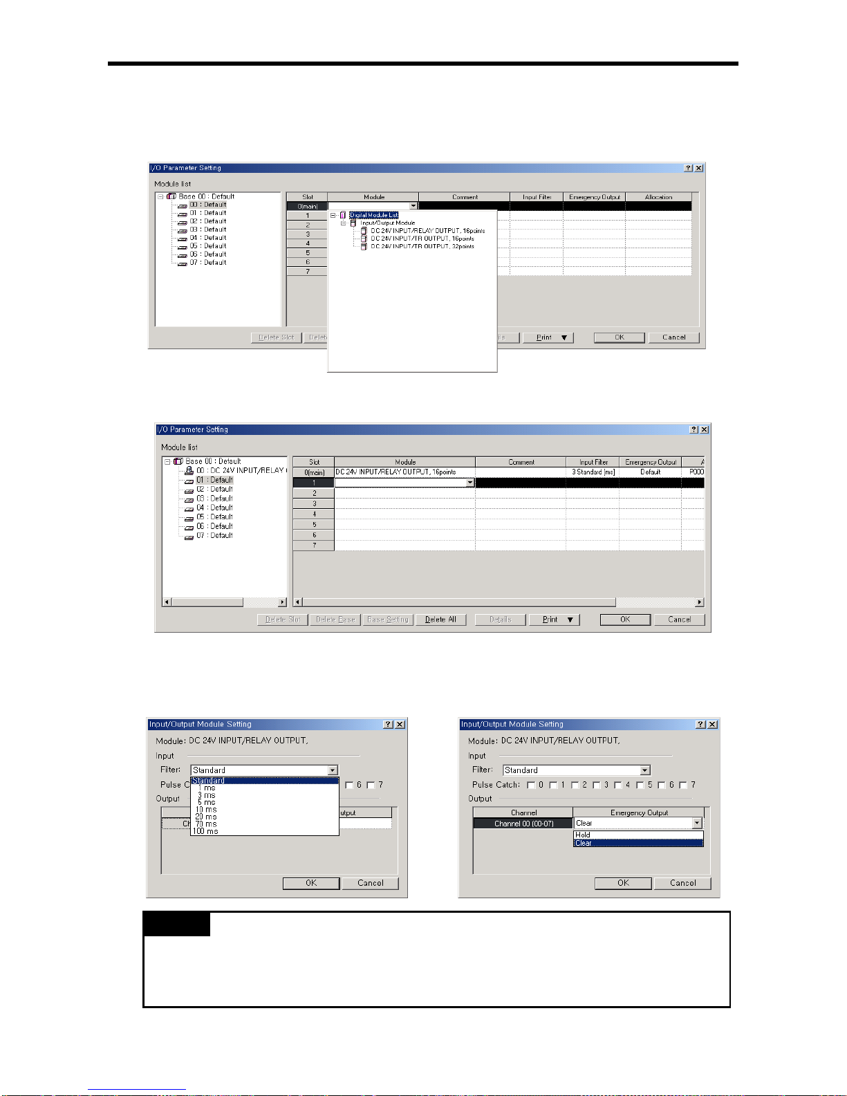
Chapter 6 CPU Functions
6.2.2 I/O parameter setting
This setting is to set and reserve each I/O information. Clicking 『I/O Parameter』 in the project
window shows the following setting window.
Clicking 『Module』 in 『Slot Position』 indicates a list of modules, in which you may set I/O
corresponding to the ac tual sy stem. Then, the follow ing window is display ed.
Clicking 『Details』 in 『Slot Position』 s hows the f ollo wing window to set filter and emergency output.
Remark
(1) If sett ings are d iff er ent wi th I /O m od ule ac tua ll y acc es sed , “ Inc ons ist ent m od ul e type error” occ urs ,
displaying error.
(2) Without settings, CPU reads each I/O module information and operates.
6- 3

Chapter 6 CPU Functions
6.3 Self-diagnosis Function
6.3.1 Saving of error log
CPU module logs errors occurred so that the causes will be identified and fixed easily. Clicking
『Error/Warning』 of 『Online』 shows the current error and previous error log.
Item Description Remarks
Error/Warning Display the current error/warning. -
Error Log Display a log of error/warning occurred. Saving up to 100
Remark
(1) Saved data are not delete d until sel ecting a menu of XG5000 and clicking “Delete”.
(2) “H” type display s D at a a nd Time.
6.3.2 Troubleshooting
(1) Trouble types
Trouble occurs due to PLC itself, system configuration error or abnormal operation result detected. Trouble
is divided into trouble mode stopping operation for the safety and warning mode generating alert to user
with a mode in trouble.
The causes troubling PLC system are as follows.
(a)
PLC hardware trouble
(b) System configuration error
(c) Operation error while operating user program
(d) Error detected ow ing to ext e rna l d evi ce i n tro ubl e
6- 4

Chapter 6 CPU Functions
(2) Operation mode if trouble occurs
PLC system logs any trouble occurred in flag and determines whether to stop or resume operation
depending on trouble mode .
(a) PLC hardware trouble
In case an error occurs so that PLC such as CPU module and power module may not work nor mally,
the system is h alt ed, b ut any warning may not interfere with the operation.
(b)
Operation error while operating user program
Representing an error occurred during operation of user program, in case of numeric operation error,
it displays the error in error flag but the system resumes operating. However, if the operation time
exceeds by the ope rati on mo nit o ring t i me limit and I/O module does not control it normally, the system
is halted.
(c)
Error detected owing to external device in trouble
Representing the detection of external device to be controlled by users program of PLC, if an error is
detected, the system is halted, but any warning may not interfere with the operation.
Remark
(1) If any trouble occurs, the trouble content is saved in a special relay %FD1.
(2) For details of flag , refer to the app endi x 1 Flag List.
6- 5

Chapter 6 CPU Functions
6.4 Remote Functions
CPU module may change operati on by communi cati on as well as by key swit ches mounte d on the modu le. To
operate it remotely, it is necessary to set ‘RUN/STOP’ switch to ‘STOP’.
(1) Remote operations are as follows.
(a) Operable by accessing to XG5000 through RS-232C port mounted on CPU modu le.
(b) Can operate other PLC connected to PLC network with CPU module connected to XG5000.
(2) Remote RUN/STOP
(a) Remote RUN/STOP is the externally controlled RUN/STOP function.
(b) It is convenient w hen C PU modul e i s lo cat ed at a po sit ion ha rd to cont rol o r wh en C PU modul e
within control panel is to control RUN/S TOP functio n remo tely.
(3) Remote DEBUG
(a) it manages debugging remot ely when remote mode is STOP. Namely, DEBUG operation is to execute
program operation depending on designated operation condi tions .
(b) Remote DEBUG is a convenient function when confirming program operation status or data during
system debugging.
(4) Remote Reset
(a) Remote reset is to reset CPU module remotely if an error occurs at a place hard to directly control
CPU module.
(b) Like operation by switches, it supports ‘Reset’ and ‘Overall Reset’.
Remark
For details regarding remote functions, refer to ‘Online’ of XG5000 Users Manual.
6- 6

Chapter 6 CPU Functions
6.5 Forced Input/Output On and O f f Function
Force I/O function is used to force to turn I/O areas on or off, regardless of program results.
6.5.1 Force I/O setup
Click『 Online 』-『 Force I/O 』.
Item Description
Move address Select base and slot
Application Set whether to allow or not Force I/O
Single
Flag Set whether to allow or not Force I/O by bits.
Data Set Force I/O data on or off by bits.
Select All Set to allow Force I/O with all I/O area on
Delete All
Delete to allow Force I/O with all I/O area off.
Setting device Display I/O area set as a bit.
6- 7

Chapter 6 CPU Functions
6.5.2 Processing time and processing method of Force Input/Output On and Off
(1) Forced Input
Regarding input, at the time of input refresh it replaces the data of contact set as Force On/Off among
data read from input module with the data as Force and updates input image area. Therefore, user
program execute s ope ra tio ns w i th a ctual inp ut da ta w hile For ce i npu t a rea is operated with da ta s et a s
Force.
(2) Forced Output
Regarding output , at the ti me o f o utput refresh upon the execution user program operation, it replaces
the data of contact set as Force On/Off among data of output image area containing operation results
with data set as Force and outputs the data in output module. Unlike (Force) input, the output image
area is not changed by Force On/Off setti ng.
(3) Cautions when using Force I/O function
(a) It operates from the time when I/O is individually set as ‘Allow’ after setting Force data.
(b) It is possible to set Force input although I/O module is not actually mounted.
(c) Despite of the power changed Off -> On, operation mode c han ge s o r any op er ati on by p res sing r ese t
key, the data of which On/Off is set before is kept in CPU module.
(d) Even in STOP mode, Force I/O data is not removed.
(e) To set new dat a fro m t he b egin nin g, it i s ne cess ary to d e selec t all settin g s o f I /O by u sing ‘ Del ete Al l ’
option.
6- 8

Chapter 6 CPU Functions
6.6 Direct Input/Output Operation
Refreshing I/O operates after completion of scan program. If data of I/O is changed while program is
scanned, it does not refreshed at the changed moment. Refreshed I/O data is applied after ‘END’ instruction
on program.
In order to refresh I/O data during program execution, use ‘DIREC_IN, DIREC_OUT’ function to read in put
contact point immediately and use it for operation, or output ope rati on resul t immediately .
Program outputti ng data 2# 01 11_ 011 1_0 111 _01 11 to 32 point transistor o utput model eq ui pped at
extension module slot 4 during scan.
(1) Input base number 0 and slot number 4 where output module is e quip ped
(2) Since data to outpu t i s 1 6 bit d uring sca n, enabl e low er 16 bi t among value of MASK_L
(16#FFFF0000)
(3) If execution condition (%IX0.0.0) is On, DIREC_O (Immediate refresh of output module) is executed
and data of output module is set as 2#0111_0 111 _01 11_0 111.
Remark
1) For detail of DIREC_IN,DIREC_OUT function, refer to XGI/XGR/XEC instruction manual
2) In case of us ing DIR EC_IN,DI REC_OUT function , the valu e is applie d immedi ately. T hey have h igher
priority than forced I/O.
6- 9

Chapter 6 CPU Functions
6.7 Diagnosis of External Device
This flag is provided for a user to diagnose any fault of external device and, in turn, execute halt or warning of
the system. Use o f thi s fl ag di splay s fa ult s o f e xte rnal device without a ny complicated program p repared and
monitors fault location without any specific device (XG5000 and etc) or source program.
1) Detection and classi fication of fault s in exte rnal devi ce
(1) The trouble (fault) of external device may be detected by user program and largely divided, depending
on the type, into error and warning; the former requires halt of PLC operation and the latter simply
displays the sta tu s w hil e P LC ke eps w or king .
(2) ‘Heavy t rouble ’ uses ‘ _ANC_ERR’ flag and ‘Light troubl e’ uses ‘_ANC_WB’ flag.
2) Heavy trouble of external device
(1) In case of detecting heavy trouble of external device at user program, write error code defined by user at
system flag ‘ANC_ERR’ and turn on _CHK_ANC_ERR flag. If _CHK_ANC_ERR flag is on, at the end
of scan, ‘_ANNUN_ER’ bit of ‘_CNF_ER’, system error rep rese ntati ve fl ag, is on an d PLC turns off all
output of output modu le (it c an b e differ ent ac cordi ng to the sett ing of bas ic param eter) and b ecom es
error status (Error LED flickers with 1s cycle)
(2)
In case of heavy trouble, y ou can kn ow the rea son by che cking ‘_ANC_ERR' flag.
(3) To turn off the ERR LED caused by flag detecting heavy trouble of external device, reset or restart PLC
Example)
3) Light trouble o f e xte rnal devi ce
(1) In case of detecting heavy trouble of external device at user program, write error code defined by user at
system flag ‘ANC_WAR’ and turn on _CHK_ANC_WAR flag. If _CHK_ANC_WAR flag is on, at the end
of scan, ‘_ANNUN_WAR’ bit of ‘_CNF_WAR’, system warning representative flag, is on. When light
trouble occurs, LED flickers with 2s cycle.
(2) In case of heavy trouble, you can know the reason by checking ‘_ANC_WAR' flag.
(3) If _CHK_ANC_WAR is off, light trouble status is canceled and Error LED is off.
Example)
Error
Error
6- 10
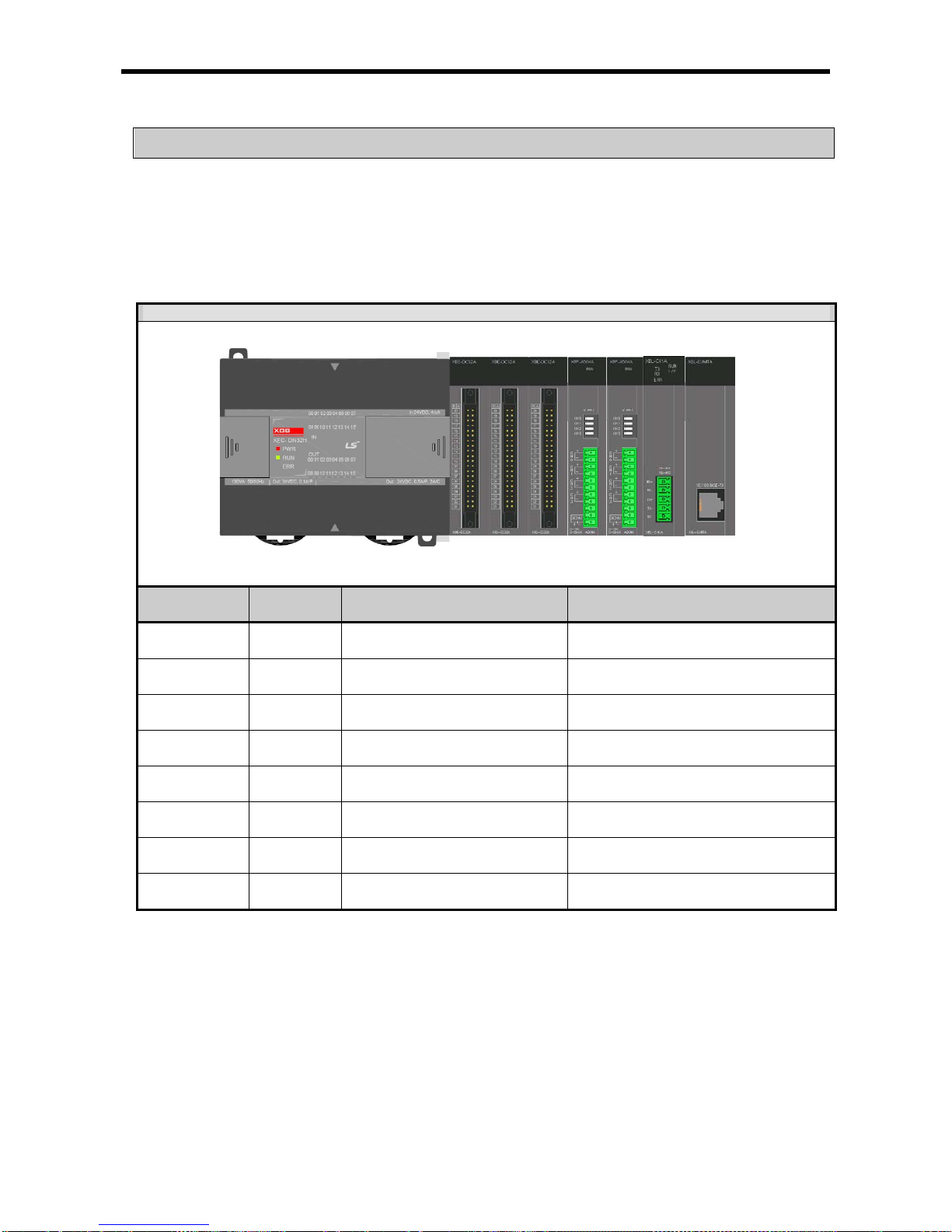
Chapter 6 CPU Functions
6.8 Allocation of Input/Output Number
Allocation of I/O number is to allocate an address to every I/O of each module to read data from input module
and output data to output module when it executes operations.
XGB series adopts each I/O 64 points occupation to every module .
(1) Allocation of I/O number
64 points are allocated to every module (incl. special, communi cation ).
System Configuration
Number of
Connection stage
Type I/O allocation Remarks
0
XECDN32H
Input : %IX0.0.0 ~ %IX0.0. 63
Output: %QX0.0.0 ~ %QX0.0.63
Real input : %IX0.0.0 ~ %IX0.0.15
Real output: % QX0.0. 0 ~ %Q X0 .0.15
1
XBEDC32A
Input : %IX0.1.0 ~ %IX0.1. 63
Output: %QX0.1.0 ~ %QX0.1.63
Real input : %IX0.1.0 ~ %IX0.1.31
2
XBETN32A
Input : %IX0.2.0 ~ %IX0.2. 63
Output: %QX0.2.0 ~ %QX0.2.63
Real output: %QX0.2.0 ~ %QX 0.2 .31
3 XBL-C41A
Input : %IX0.3.0 ~ %IX0.3. 63
Output: %QX0.3.0 ~ %QX0.3.63
-
4
XBFAD04A
Input : %IX0.4.0 ~ %IX0.4. 63
Output: %QX0.4.0 ~ %QX0.4.63
-
5
XBFDV04A
Input : %IX0.5.0 ~ %IX0.5. 63
Output: %QX0.5.0 ~ %QX0.5.63
-
6
XBEDC32A
Input : %IX0.6.0 ~ %IX0.6. 63
Output: %QX0.6.0 ~ %QX0.6.63
Real input : %IX0.6.0 ~ %IX0.6.31
7
XBETN32A
Input : %IX0.7.0 ~ %IX0.7. 63
Output: %QX0.7.0 ~ %QX0.7.63
Real output: % QX0.7. 0 ~ %Q X0 .7.31
Empty I/O point is available for internal relay.
6- 11

Chapter 6 CPU Functions
In case of using monitor function of XG5000, I/O allocation information is displayed.
I/O contact point
allocation information
Description of each module
6- 12

Chapter 6 CPU Functions
6.9 Online Editing
It is possible to modify program and communication parameter during operation of PLC without control
operation stopped. The following describes basic modification. For details of modifying program, refer to
XG5000 Users Manu al.
Items to be modified duri ng operatio n are as follow s.
• Program
• Communication parameter
(1) It displays programs that are currently running.
(2) Click 『Online』-『Start Online Edi tin g』.
6- 13
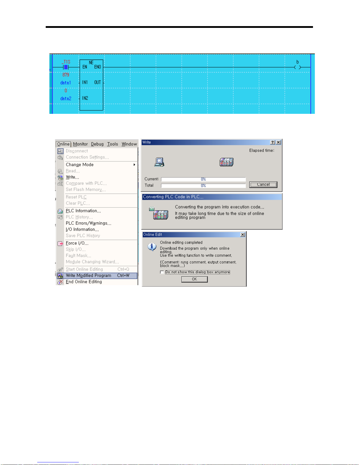
Chapter 6 CPU Functions
(3) If you modify prog ram, backgro und co lor chan ges to indic ates sta rt of onli ne editin g.
(4) Upon the modification of program, click 『Online』-『Write Modified Program』.
6- 14

Chapter 6 CPU Functions
(5) Upon the writing of program, click 『Online』-『End Onli ne Editing』.
(6) The program background returns and the program modification during run is completed.
Remark
▪ For par ameter modification during run, change each parameter on XG-PD and click『Online』-『Write
Modified Program 』.
6- 15

Chapter 6 CPU Functions
6.10 Reading Input/Output Information
It monitors information of individual modules consisted of XGB series system.
(1) Click『Online』-『I/O Info』. Then, information of each module connected to the system is monitored.
(2) If clicking Details after selecting a module, it displays detail information of a selected module.
6- 16

Chapter 6 CPU Functions
6.11 Monitoring
It monitors system information of XGB series system.
(1) Clicking『Monitor』 displays the following sub-menus.
(2) Items and descriptions
Item Description Remarks
Start/Stop Monitoring Designate the start and stop of monitor. Click for reverse turn.
Pause Pause monitoring. -
Resume Resume paused monitor. -
Pausing Conditions
Pause monitoring if a preset value of device
corresponds to condition.
Monitor resumes;
clicking for resume.
Change Current Value
Change the present value of currently selected
device.
-
System Monitoring Monitor general system information. -
Device Monitoring Monitor by devi ce (type ). -
Trend Monitoring Monitor trend of device set in the system.
For details, refer to
XG5000 Users Manu al.
Custom Events
Monitor the value of device set when an event set
by a user occurs.
Data Traces Trace the value of device.
6- 17
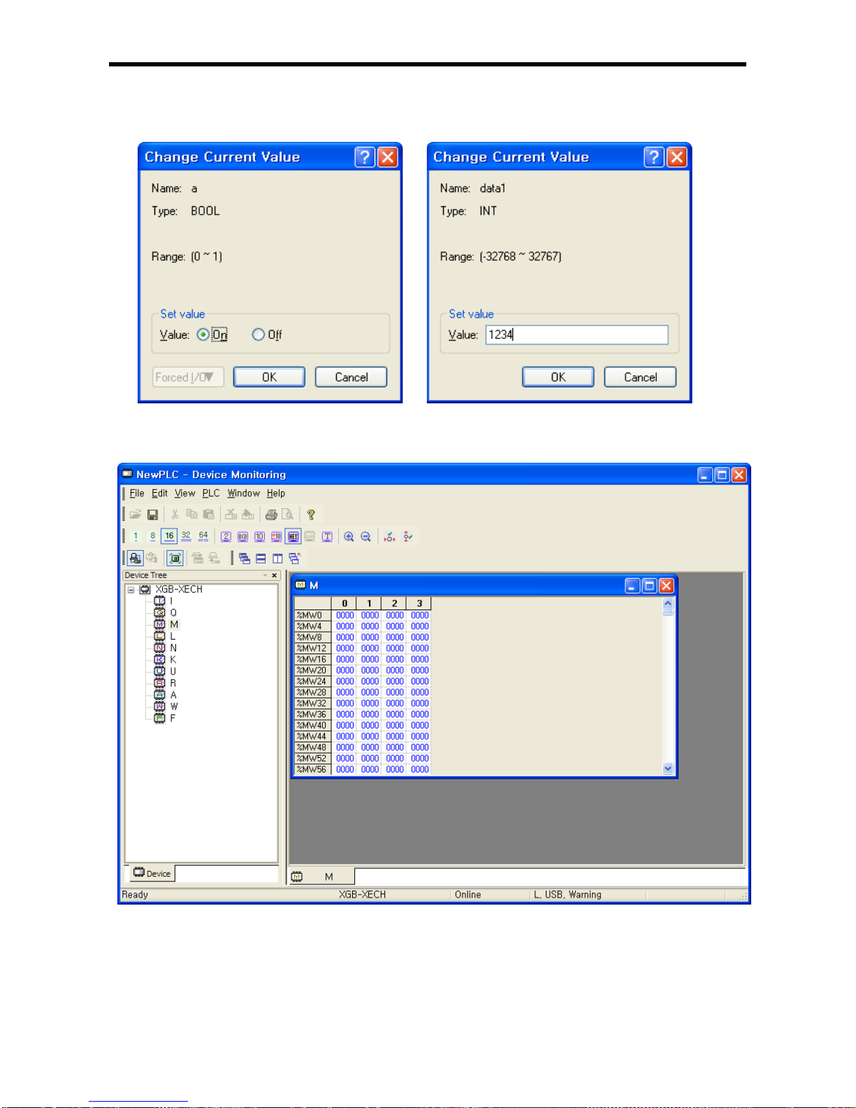
Chapter 6 CPU Functions
(a) Change current value
It changes the current value of each device selected in the current program window.
(b) Device monitoring
It monitors by device (ty pe).
6- 18

Chapter 6 CPU Functions
(c) Pausing conditi ons
It stops monitoring in case a device value set in the program corresponds.
(d) Trend monitoring
It displays device value s graphi cally .
6- 19

Chapter 6 CPU Functions
(e) Custom events
1) It monitors detail information when an event set by a user occurs. Additional u ser eve nt may be
registered.
2) It sets basic setting and relative device.
If rising edge of %MX0 device occurs, it records the message of an alarm, “Out of order Water Tank 1”
and the device values of DATA (%MW0), %MW100, tog_4s device are recorded.
3) Set the relative devi ce(s).
6- 20

Chapter 6 CPU Functions
4) Monitor event history of custom event.
5) Double-cli ckin g a n u mbe r p rodu ced moni to r s t he rela tiv e val ue s o f dev ice and the detail message as
follows.
Remark
▪For details of monitor, refer to XG5000 Users Manual.
6- 21

Chapter 6 CPU Functions
6.12 RTC function
XGB PLC supports the RTC (clock) function and user can use this function for time management of
system or error log. RTC function is executed steadily when power is off or instantaneous power cut
status. Current time of RTC is renewed every scan by system operation status information flag.
6.12.1 How to use
(1) Reading/setting clock data
(a) Reading or setting from XG5000
1) Click『Online』의『PLC Information』.
2) Click PLC RTC tap of PLC Information』.
3) In case the user wants to send the clock of PC to PLC, press ‘Synchronize PLC with PC clock’.
4) In case the user wants t o send the c lock the user wants, c hange the se tting val ue of T ime box
and press ‘Send to PLC’.
(b) Reading by flag
The user can monitor as follows by flag
Flag for RTC Data Contents
_MON_YEAR h0599 99 year 5 month
_TIME_DAY h1512 12 date 15 hour
_SEC_MIN h4142 42 minute 41 second
_HUND_WK h2001 20xx year, Monday
Time data of _TIME_DAY is indicated as 24 hour type.
6- 22

Chapter 6 CPU Functions
(c) Modification of clock data by program
You can set clock data by program.
It is used when you make system to set clock manually by external Digit switch or modify clock
periodically throug h netwo rk.
‘RTC-SET’ function block is used to write the c lock data to a clock. I f you input the clock da ta and
execute the function block, it writes the clock data to a clock at the scan end. For further
information, refer to an instruction manual.
There is another method not using a function block. Input the clock data at the following area and
turn ON ‘_RTC_WR’.
Flag for writing clock Content Setting range
_MON_YEAR_DT
Month/Year
1984 ~ 2163 year, 1 ~12 month
_TIME_DAY_DT
Hour/day
1 ~ 31 day, 0 ~ 23 hour
_SEC_MIN_DT
Second/Minute
0 ~ 59 minute, 0 ~59 second
_HUND_WK_DT
Hundred year/date
0 ~ 6
You can write clock data with out using function block. Write cloc k data at the abov e area and turn
on ‘_RTC_WR’.
• When form of clock data is wrong, the value is not written.
(But when dat e i s w r ong , e r ror i s no t d et e cted and wri tt en it sel f. )
• After writing clock data, monitor clock-related device for check
(d) How to express the date
Number 0 1 2 3 4 5 6 Date
Sunday
Monday
Tuesday
Wednesday
Thursday
Friday
Saturday
(2) Deviation of clock data
±2.2s / 1 d
(1) Initially , R TC may not h ave any clo ck d ata .
(2) When using the CPU module, first make sure to set the accurate clock data.
(3) If any dat a out o f the clo ck da ta rang e is written into RTC, i t doe s n ot wor k p ro perly .
i.e.) 14M 32D 25H
(4) RTC may stop or have an error due to abnormal battery and other causes. The error is released if a
new clock data is written.
Remark
6- 23

Chapter 6 CPU Functions
6.13 External Memor y Module
You can save user pr ogram safel y or download user pr ogram to PLC w ithout special handl ing when user
program is damaged by using external memory module in XGB PLC
.
6.13.1 Structure
6.13.2 How to use
With the following handling, you can run PLC with program saved in memory module.
(1) Save user program at external memory module
(a) Set switch of memory module as 0
(b) Install memory module at the RS-232C port of main unit
- After installation, program and parameter is saved into memory module and READ LED is on
- If Saving program and parameter is complete, READ LED is off
(c) separate memory module from main unit.
(2) Save user program of external memory module at main unit
(a) Set operation mode of main unit as STOP
- In RUN mode, you can’t save program
(b) Set switch of memory module as 1.
(c) Install memory module
- Install it at the RS-232C port of main unit.
- If PLC program and parameter is written, WRITE LED is on.
- If saving program and parameter is complete, WRITE LED is off.
(d) If you change op erati on mode of PLC into RU N, P LC o per at es with pr ogram and parameter s av ed
in memory module.
(3) In case LED flickers
(a) When you execute writing of memory module in case operation mode of PLC is RUN.
(WRITE LED flickers)
(b) When the PLC type of program of memory module doesn’t correspond with actual PLC type.
(WRITE LED flickers)
(c) When mode switch of memory module is not “0”, “1” (RUN LED flickers)
(d) When interface with main unit is not normal (READ LED flickers)
-. Program and parameter of XG5000, parameter and information about link enabled are all saved.
-. Don’t run PLC while external memory module is installed.
-. When READ/WRITE LED is on, don’t remove memory module.
Remark
RS-232C connector
RUN LED
WRITE LED
READ LED
0 : READ mode
1 : WRITE mode
6- 24
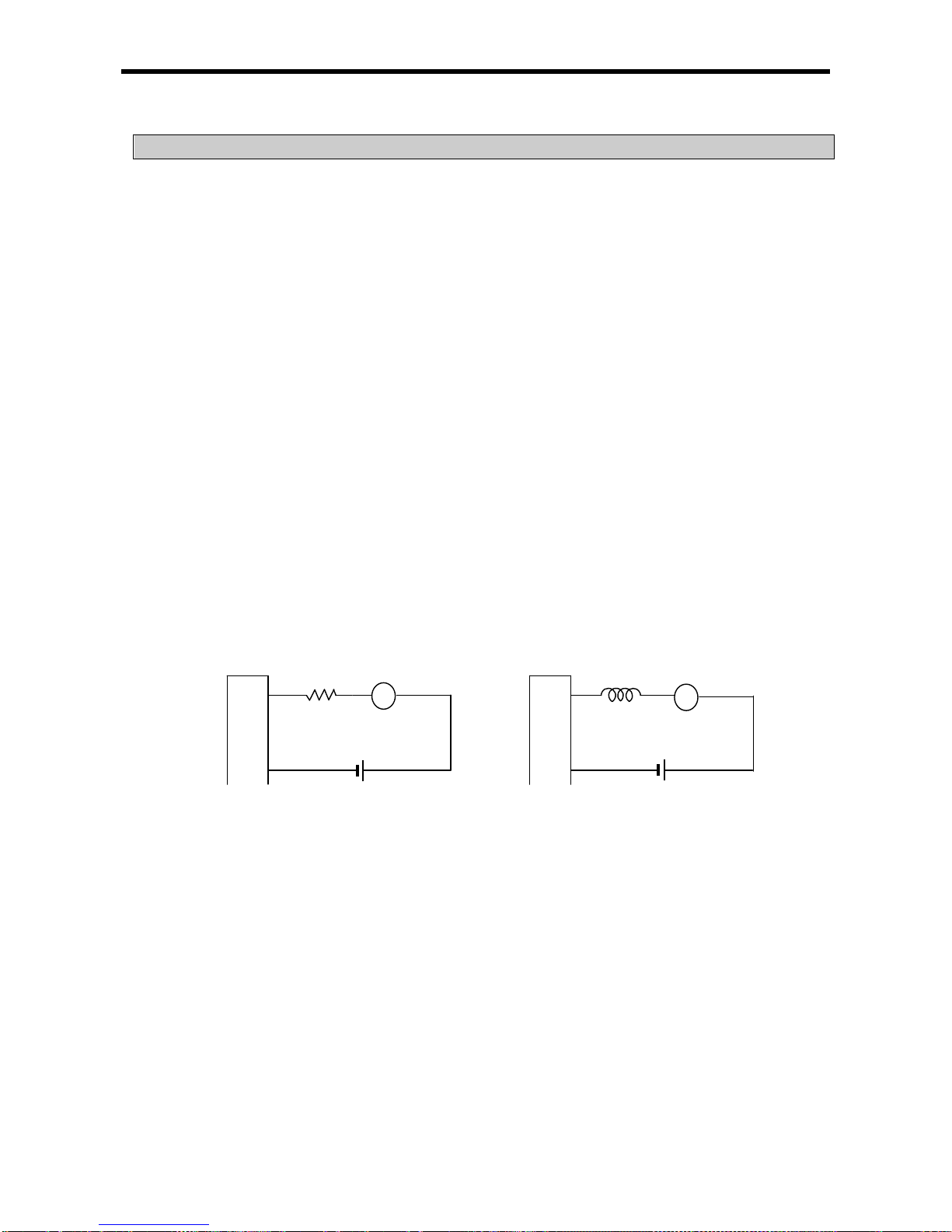
Chapter 7 Input/Output Specifications
Chapter 7 Input/Output Specifications
7.1 Introduction
Here describes the notices when selecting digital I/O module used for XGB series.
(1)
For the type of digital in put, ther e are t wo t ypes such as c urrent s ink inp ut and c urrent s ource
input.
(2) The number of max. Simultaneous in put contact point is different ac cording to module type. It
depends on the input voltage, ambient temperature. Use input module after checking the
specification.
(3) When response to h igh speed input is necessary, us e interrupt input cont act point. Up to 8
interrupt points are supported.
(4) In case that open/close frequenc y is high or it is used f or conductive load open/close, use
Transistor output module o r triac output m odule as the durabilit y of Relay Output Modu le shall
be reduced.
(5) For o utput modul e to run the c onductive (L) l oad, m ax. open/close f requency shou ld be use d
by 1second On, 1 second Off.
(6) For outp ut module, in case that counter tim er using DC/DC Converter as a load was us ed,
Inrush current ma y flow in a certain cycle when it is O N or during operation. In this case, if
average current is selected, it may cause the failure. Accordingly, if the previous load was
used, it is recommended to connect resistor or inductor to the load in s erial in ord er to reduce
the impact of Inrush current or use the large module having a max. load current value.
Output
module
Resistor
Load
L
Inductor
Load
7-1

Chapter 7 Input/Output Specifications
(7) Relay life of Relay output module is shown as below.
Max. life of Relay used in Relay output module is shown as below.
Open/Close times (
×
10000)
100
50
30
20
10
100
10 5 3 2 1
0.5
Open/Close current (A)
AC 250V Resistive load
DC 30V Resistive load
AC 125V Resistive load
7-2

Chapter 7 Input/Output Specifications
(8) A clamped terminal w ith sleeve can not be used for the XGB terminal strip. The c lamped terminals
suitable for terminal strip are as follows (JOR 1.25-3:Daedong Electr icity in Korea).
(9) The cable size con nected to a terminal strip s hould be 0.3~0.75㎟ stranded c able and 2.8 ㎜ thick.
The cable may have different current allowance depending on the insulation thickness.
(10) The coupling torque available for fixation screw and terminal strip screw should follow the table below.
Coupling position
Coupling torque range
IO module terminal strip screw (M3 screw)
42 ~ 58 N·㎝
IO module terminal strip fixation screw
(M3 screw)
66 ~ 89 N·㎝
(11) Relay life graph is not writt en based on real use. (This is not a guaranteed value). So cons i der margin.
Relay life is specified under following condition.
(a) Rated voltage, load: 3 million times: 100 million times
(b) 200V AC 1.5A, 240V AC 1A (COS¢ =0.7): 1 million times
(c) 200V AC 0.4A, 240V AC 0.3A (COS¢ =0.7): 3 million times
(d) 200V AC 1A, 240V AC 0.5A (COS¢ =0.35): 1 million times
(e) 200V AC 0.3A, 240V AC 0.15A (COS¢ =0.35): 3 million times
(f) 24V DC 1A, 100V DC 0.1A (L/R=7ms): 1million times
(g) 24V DC 0.3A, 100V DC 0.03A (L/R=7ms): 3million times
(12) Noise can be insert ed into in put module. To prevent this noise, the user can set filter for in put d el a y in
parameter. Consider the environment and set the input filter time.
Input filter time (ms)
Noise signal pulse size (ms)
Reference
1
0.3
3 1.8
Initial value
5 3
10 6
20
12
70
45
100
60
6.0mm or less
6.0mm or less
7-3

Chapter 7 Input/Output Specifications
(a) Setting input filter
1) Click I/O Parameter』in the project window of XG5000
2) Click『Module』 at the slot location.
7-4

Chapter 7 Input/Output Specifications
3) Set I/O module really equipped.
4) After setting I/O module, click Input Filter.
5) Set filter value.
7-5

Chapter 7 Input/Output Specifications
(b) Setting output status in case of error
1) Click Emergency Out in the I/O parameter setting window.
2) Click Emergency Output.
If it is selected as Clear, the output will be Off and if Hold is selected, the output will be kept.
7-6

Chapter 7 Input/Output Specifications
7.2 Digital Input Specifications of Main Unit
7.2.1 XEC-DR32H / XEC-DN32H input unit (Source/Sink type)
Model
Specification
Main unit
XEC-DN32H(/DC)
XEC-DP32H
XEC-DR32H XEC-DR32H/D1
Input point 16 point
Insulation method Photo coupler insulation
Rated input voltage DC24V DC12/24V
Rated input current
About 4 ㎃ (point 0~7: About 10 ㎃)
About 5/10mA
(point 0~7: about 7/15mA)
Operation voltage range DC20.4~28.8V (ripple rate < 5%)
DC9.5~30V
(ripple rate < 5%)
On Voltage/Current
DC19V or higher / 3 ㎃ or higher DC9V or higher / 3 ㎃ or higher
Off Voltage/Current
DC6V or less / 1㎃ or less
DC 5V or less /
1㎃ or less
Input resistance About 5.6 ㏀ (%IX0.0.0~%IX0.0.7: About 2.7㏀)
About 2.7㏀ (%IX0.0.0
~%IX0.0.7: About 1.8㏀)
Response
time
Off → On
1/3/5/10/20/70/100㎳ (set by CPU parameter) Default: 3 ㎳
On → Off
Insulation pressure
AC560Vrms / 3Cycle (altitude 2000m)
Insulation resistance
10 ㏁ or more by Mega ohmmeter
Common method 16 point / COM
Proper cable size 0.3 ㎟
Current consumption
200 ㎃ (when all point On)
Operation indicator Input On, LED On
External connection method 24 points connecting connector (M3 X 6 screw)
Weight 500g 600g
Circuit configuration
No. Contact No.
Conta
ct
Type
TB1 RX
TB2 485+
TB3 TX
TB4 485-
TB5 SG
TB6 00
TB7 01
TB8 02
TB9 03
TB10 04
TB11 05
TB12 06
TB13 07
TB14 08
TB15 09
TB16 10
TB17 11
TB18 12
TB19 13
TB20 14
TB21 15
TB22 COM
TB23
24G
DC24V
Internal
circuit
R
F
0
B10
COM
Photocoupler
Terminal block no.
A03
B02
R
7-7

Chapter 7 Input/Output Specifications
TB24 24V
7.2.2 XEC-DR64H / XEC-DN64H input unit (Source/Sink Type)
Model
Specification
Main unit
XEC-DN64H XEC-DR64H XEC-DR64H/D1
Input point
32 point
Insulation method
Photo coupler insulation
Rated input voltage
DC24V
DC 12/24V
Rated input current
About 4 ㎃ (point 0~7: About 10 ㎃)
About 5/10㎃
(point 0~7: About 7/15㎃)
Operation voltage range DC20.4~28.8V (ripple rate < 5%)
DC 9.5~30V
(ripple rate < 5%)
On Voltage/Current
DC19V or higher / 3 ㎃ or higher
DC9V or higher / 3 ㎃ or
higher
Off Voltage/Current
DC6V or less / 1㎃ or less
DC5V or less / 1㎃ or less
Input resistance
About 5.6 ㏀ (%IX0.0.0~%IX0.0.7: About 2.7 ㏀)
About 2.7㏀ (%IX0.0.0
~%IX0.0.7: About 1.8㏀)
Response
time
Off → On
1/3/5/10/20/70/100㎳ (set by CPU parameter) Default: 3 ㎳
On → Off
Insulation pressure
AC560Vrms / 3Cycle (altitude 2000m)
Insulation resistance
10㏁ or more by Mega ohmmeter
Common method
16 point / COM
Proper cable size
0.3㎟
Current consumption
200㎃ (when all point On)
Operation indicator
Input On, LED On
External connection method
42 point connecting connector (M3 X 6 screw)
Weight
800g
900g
Circuit configuration
No. contact No.
con
tact
type
TB1 RX
TB2 485+
TB3 TX
TB4 485-
TB5 SG
TB6 00
TB7 01
TB8 02
TB9 03
TB10 04
TB11 05
TB12 06
TB13 07
TB14 08
TB15 09
TB16 10
TB17 11
TB18 12
TB19 13
TB20 14
TB21 15
TB22 COM
TB23 NC
TB24 16
TB25 17
TB26 18
TB27 19
TB28 20
TB29 21
TB30 22
TB31 23
TB32 24
TB33 25
TB34 26
TB35 27
TB36 28
TB37 29
TB38 30
TB39 31
TB40 COM
TB41
24
DC24V
Internal
circuit
R
0F
00
TB6
COM0
Photo coupler
TB21
TB22 R DC24V
R
1F
10
TB24
COM1
Photo coupler
Terminal block no.
TB39
TB40
R
7-8
 Loading...