


Introduction
Introduction
Hello. Thank you for choosing LS Mecapion L7 Series.
This user manual describes how to use the product and what precautions to take.
Failure to comply with guidelines may cause injury or product damage. Be sure to read this
user manual before you use the product and follow all guidelines.
The contents of this manual are subject to change without prior notice depending on software
versions.
No reproduction of part or all of the contents of this manual in any form, by any means or for any
purpose, shall be permitted without the explicit written consent of LS Mecapion.
The patent, trademark, copyright and other intellectual property rights in this user manual are
reserved by LS Mecapion. No use for purposes other than those related to the product of LS
Mecapion shall be authorized.
i

Safety Precautions
Precautions
Definition
Danger
Caution
Safety Precautions
Safety precautions are categorized as either Danger or Caution, depending on the
seriousness of the precaution.
Danger
Caution
Certain conditions that are listed as Caution may also result in serious injury .
Failure to comply with guidelines may cause death or seriou s injury.
Failure to comply with guidelines may cause injury or property damage.
Electric Shock Precautions
Before wiring or inspection tasks, turn off the power. Wa it 15 minu tes until the charg e lamp
goes off, and then check the voltage.
Be sure to ground both the servo drive and the servo motor.
Only specifically trained professional engineers are permitted to perform wiring tasks.
Perform wiring tasks after you install both the servo drive and the servo motor.
Do not operate the device with wet hands.
Do not open the servo drive cover while in operation.
Do not operate the device with the servo drive cover removed.
Even if the power is off, do not remove the servo drive cover.
Fire Prevention Precautions
Install the servo drive, the servo motor, and the regenerative resistance on non-combustible
material.
In case of servo drive malfunction, disconnect the input power.
ii

Safety Precautions
Environment
Conditions
Servo Drive
Servo Motor
Caution
Installation Precautions
Store and use the product in an environment as follows:
Usage temp. 0 ~ 50 ℃ 0 ~ 40 ℃
Storage temp. -20 ~ 65 ℃ -20 ~ 60 ℃
Usage
humidity
Storage
humidity
Altitude Below 1000 m
Spacing
Others
Below 90% RH (non-condensing)
When installing 1 unit:
More than 40 mm space at the top and
bottom of the control panel
More than 10 mm space at the left and
right sides of the control panel
When installing 2 or more units:
More than 100 mm space at the top of
the control panel
More than 40 mm space at the bottom
of the control panel
More than 30 mm space at the left and
right sides of the control panel
More than 2 mm between units
Refer to "2.2.2 Installation Inside the
Control Panel."
Install in a location free from iron, corrosive gas, and combustible gas.
Install in a location free from vibration or shock.
Below 80% RH
Below 90% RH
Make sure that the installation orientation is correct.
Do not drop the product or expose it to excessive shock.
Install in a location that is free from water, corrosive gas, combustible gas, or flammable
material.
Install in a location that can support the weight of the product.
Do not stand on the product or place heavy objects on top of it.
Be sure to maintain the specified spacing when you install the servo drive.
Be sure not to get conductive or flammable debris inside either the servo drive or the servo
motor.
Firmly fix the servo motor onto the machine.
Be sure to install a servo motor with a gearbox in the specified direction.
Do not touch the rotating unit of the servo motor while you operate the machine.
Do not apply excessive shock when you connect a coupling to the servo motor shaft.
Do not place a load on the servo motor shaft that is heavier than specified.
iii

Safety Precautions
Caution
Caution
Caution
Wiring Precautions
Be sure to use AC 200-230 V for the input power of the servo drive.
Be sure to connect the servo drive ground terminal.
Do not connect commercial power directly to the servo moto r.
Do not connect commercial power directly to the U, V, W output terminal of the servo drive.
Directly connect U, V, W output terminals of the servo drive and U, V, W input terminals of the
servo motor, but do not instal l a magnetic contactor between the wiring.
Be sure to use a pressurized terminal with an insulation tube when you connect the power
terminal for the servo drive.
When wiring, be sure to separate the U, V, and W cables for the servo motor power and
encoder cable.
Be sure to use robotic cable if the motor requires movement.
Before you perform power line wiring, turn off the input power of the servo drive, and then wait
until the charge lamp goes off completely.
Be sure to use shielded twisted-pair wire for the pulse command signal (PF+, PF-, PR+, PR-),
speed command signal (SPDCOM), and torque command signal (TRQCOM).
Precautions for I nit ial Operation
Check the input voltage (AC 200-230 V) and power unit wiring before you turn on the power.
The servo must be in the OFF mode when you turn on the power.
Before you turn on the power, check the motor's ID and the encoder pulse for L7 □A □□□A.
Set the motor ID ([P0-00]) and the encoder pulse ([P0-02]) for L7 □A □□□A first after you
turn on the power.
After you complete the above settings, set the drive mode for the servo drive that is connected
to the upper level controller to [P0-03].
Refer to Chapter 1.2 "System Configuration" to perform CN1 wiring for the servo drive
according to each drive mode.
You can check the ON/OFF state for each input terminal of CN1 at [St-14].
Precautions for Handling and Operation
Check and adjust each parameter before operation.
Do not touch the rotating unit of the motor during operation.
Do not touch the heat sink during operation.
Be sure to attach or remove the CN1 and CN2 connectors when the power is off.
Extreme change of param eters may cause system instability.
iv

Safety Precautions
Caution
Caution
Caution
Caution
Caution
Precautions for Use
Install an emergency s top circuit on the outside to immediately stop operation if necessary.
Reset the alarm when the servo is off. Be warned that the system restarts immediately if the
alarm is reset while the servo is on.
Minimize electromagnetic interference by using a noise filter or DC reactor. Otherwise, adjacent
electrical devices may malfunction bec aus e of the inter fer en c e.
Use only the specified combinations of servo drive and servo motor.
The electric brake on the servo motor keeps the mortor at a standstill. Do not use it for ordinary
braking.
The electric brake may not function properly depending on the brake lifespan and mechanical
structure (for example, if the ball screw and servo motor are combined via the timing belt).
Install an emergency stop device to ensure me cha nic al safe t y.
Malfunction Precautions
For potentially dangerous situations that may occur during emergency stop or device
malfunction, use a servo motor with an electric brake, or separately install a brake system on
the outside.
In case of an alarm, solve the source of the problem. After you solve the problem and ensure
safety, deactivate the alarm and start operation again.
Do not get close to the machine until the problem is solved.
Precautions for Repair/Inspection
Before performing servicing tasks, turn off the power. Wait 15 minutes until the charge lamp
goes off, and then check the voltage. Voltage may remain in the condenser even after you turn
off power and may cause an electric shock.
Only authorized personnel are permitted to perform repair, inspection or replacement of parts.
Do not modify the product.
General Precautions
This user manual is subject to change upon prod uct mod ifi ca tion or st and ards change s. In cas e
of such changes, the user m anual will be issued with a new product number.
Product Application
This product is not designed or manufactured for machines or systems that are used in
situations related to human life.
This product is manufactured under strict quality control. However, be sure to install safety
devices when applying the product to a facility where a malfunction in the product might cause
a major accident or signific ant loss.
v
Safety Precautions
Caution
EEPROM Lifes pan
EEPROM is rewritable up to 1 million times for the purpose of, among others, recording
parameter settings. The servo drive may malfunction dependi ng on the lifespan of EEPROM
when the total counts of the following tasks exceed 1 million.
EEPROM recording as a result of parameter changes
EEPROM recording as a result of alarm trigger
Respondi ng to international regulations
L7 Series responds to international regulations with standard models.
Model(Note1) Low Voltage Directive EMC Directive
L7SA001X
L7SA002X
L7SA004X
L7SA008X
EN61800-5-1 EN61800-3
L7SA010X
L7SA020X
L7SA035X
Note1) X = A or B : A = Quadr atur e Enco der Type, B = Serial Encoder Type.
※1 : For more information, please feel free to ask LS Mecapion.
※2 : Please follow the regulations of destination when exporting.
vi

Table of Contents
Table of Contents
Introduction ...................................................................................................................... i
Safety Precautions .......................................................................................................... ii
Ta b le of Contents .......................................................................................................... vii
1. Product Components and Signals ................................................................... 1-1
1.1 Product Components ..................................................................................................... 1-1
1.1.1 Product Verification ........................................................................................ 1-1
1.1.2 Part Names .................................................................................................... 1-3
1.2 System Configurat ion .................................................................................................... 1-8
1.2.1 Overview ........................................................................................................ 1-8
1.2.2 Wiring Diagram of the Entire CN1 Connector ............................................... 1-10
1.2.3 Example of Posit ion Operation Mode Wiring ................................................ 1-11
1.2.4 Example of Speed Operation Mode Wi ring ................................................... 1-12
1.2.5 Example of Torque Operation Mode Wiring .................................................. 1-13
1.2.6 Examples of Speed / Position O peration Mode Wiri ng ................................. 1-14
1.2.7 Example of Speed/Torque Operation Mode Wiring ....................................... 1-15
1.2.8 Example of Posit ion/Torque Operation Mode Wiring .................................... 1-16
1.3 Signals ........................................................................................................................ 1-17
1.3.1 Digital Input Contact S ignal .......................................................................... 1-17
1.3.2 Analog Input Contact Signal ......................................................................... 1-18
1.3.3 Digital Output Contact S ignal ........................................................................ 1-18
1.3.4 Monitor Output Signal and Output Power ..................................................... 1-19
1.3.5 Pulse Train Input Signal ................................................................................ 1-19
1.3.6 Encoder Output Si gnal ................................................................................. 1-20
2. Installation .......................................................................................................... 2-1
2.1 Servo Motor ................................................................................................................... 2-1
2.1.1 Usage Environment ........................................................................................ 2-1
2.1.2 Prevention of Excessive Shock ...................................................................... 2-1
2.1.3 Motor Connecti on ........................................................................................... 2-1
2.1.4 Load Device Connection ................................................................................ 2-2
2.1.5 Cable Installation ............................................................................................ 2-2
2.2 Servo Drive.................................................................................................................... 2-3
2.2.1 Usage Environment ........................................................................................ 2-3
2.2.2 Installation Inside the Control Panel ............................................................... 2-4
2.2.3 Power Wiring .................................................................................................. 2-5
3. Wiring Method .................................................................................................... 3-1
3.1 Internal Block Diagram .................................................................................................. 3-1
3.1.1 L7 Drive Block Diagram [L7SA001□ - L7SA004□] .......................................... 3-1
3.1.2 L7 Drive Block Diagram [L7SA008□ - L7SA035□] .......................................... 3-2
3.1.3 L7 Drive Block Diagram [L7SA050□ ] ............................................................. 3-3
3.2 Power Wiring ................................................................................................................. 3-4
3.2.1 L7 Drive Wiring Diagram [L7SA001□ - L7SA035□] ......................................... 3-4
3.2.2 L7 Drive Wiring Diagram [L7SA050□] ............................................................. 3-5
3.2.3 Dimensions for Pow er Circuit Electr ical Parts ................................................. 3-6
vii

Table of Contents
3.3 Timing Diagram ........................................................................................................... 3-10
3.3.1 Timing Diagram During Power Input ............................................................. 3-10
3.3.2 Timing Diagram at the Time of Alarm Trigger .................................................3-11
3.4 Control Signal Wiring ................................................................................................... 3-12
3.4.1 Contact Input Signal ..................................................................................... 3-12
3.4.2 Contact Output Signal .................................................................................. 3-13
3.4.3 Analog Input/Output Signals ......................................................................... 3-14
3.4.4 Pulse Train Input Signal................................................................................ 3-15
3.4.5 Encoder Output Si gnal ................................................................................. 3-16
3.5 Quadrature Encoder S ignaling Unit ( C N 2) Wiring ........................................................ 3-17
3.5.1 APCS-EAS Cable .................................................................................. 3-17
3.5.2 APCS-EBS Cable .................................................................................. 3-17
3.6 Serial Encoder Signaling Unit (CN2) Wiring ................................................................ 3-18
3.6.1 APCS-ECS Cable .................................................................................. 3-18
3.7 Multi Turn Encoder signal unit(CN2) wiring .................................................................. 3-20
3.7.1 APCS-ECS1 Cable ................................................................................ 3-20
3.7.2 APCS-EDS1 Cable ................................................................................ 3-20
3.7.3 APCS-EES1 Cable ................................................................................ 3-21
3.8 Transmission of Absolute Encoder Data ...................................................................... 3-22
3.8.1 Transmission of Absolute Encoder Data ....................................................... 3-22
4. Parameters .......................................................................................................... 4-1
4.1 How to Use the Loader .................................................................................................. 4-1
4.1.1 Names and Functions of Each Parts .............................................................. 4-1
4.1.2 Status Summary Display ................................................................................ 4-2
4.1.3 Parameter Handli ng ....................................................................................... 4-4
4.1.4 Data Display ................................................................................................... 4-8
4.1.5 External Input Contact Signal Display [ St-14] ............................................... 4-10
4.1.6 External Input Signal and Logic Definition .....................................................4-11
4.1.7 External Output Contact Signal Display [St-15]............................................. 4-19
4.1.8 External Output Signal and Logic Definition ................................................. 4-20
4.2 Parameter Description ................................................................................................. 4-26
4.2.1 Parameter System ........................................................................................ 4-26
4.2.2 Operation Status Display Parameter ............................................................ 4-27
4.2.3 System Setting Par am eter ............................................................................ 4-30
4.2.4 Control Setting Parameter ............................................................................ 4-34
4.2.5 Input/Output Setting Parameter .................................................................... 4-37
4.2.6 Speed Operation Setting Parameter ............................................................. 4-40
4.2.7 Position Operation Setting Parameter .......................................................... 4-42
4.2.8 Operation Handling Parameter ..................................................................... 4-45
4.3 Operation Status Display ............................................................................................. 4-49
4.3.1 Status Display [St-00] ................................................................................... 4-49
4.3.2 Speed Display .............................................................................................. 4-49
4.3.3 Position Display ............................................................................................ 4-49
4.3.4 Torque and Load Display .............................................................................. 4-49
4.3.5 I/O Status Display ......................................................................................... 4-50
4.3.6 Miscellaneous Status and Data Di splay ........................................................ 4-50
4.3.7 Version Display............................................................................................. 4-51
4.4 Parameter Setting ....................................................................................................... 4-52
viii

Table of Contents
4.4.1 System Parameter Setting ............................................................................ 4-52
4.4.2 Control Parameter S etting ............................................................................ 4-55
4.4.3 Analog Input/Output Parameter Setting ........................................................ 4-59
4.4.4 Input/Output Contact Point Parameter Setting .............................................. 4-61
4.4.5 Speed Operation Parameter Setting ............................................................. 4-63
4.4.6 Position Operation Parameter Setting .......................................................... 4-64
4.5 Alarms and Warnings .................................................................................................. 4-66
4.5.1 Servo Alarm Status Summary Display List .................................................... 4-66
4.5.2 Servo Warning Status Summary Display Li st ................................................ 4-68
4.6 Motor Type and ID (to be continued on the next page) ................................................ 4-69
5. Handling and Operation .................................................................................... 5-1
5.1 What to Check Before Operation ................................................................................... 5-1
5.1.1 Wiring Check .................................................................................................. 5-1
5.1.2 Drive Signal (CN1) Wiring Check ................................................................... 5-1
5.1.3 Surrounding Environment Check .................................................................... 5-1
5.1.4 Machine Status Check .................................................................................... 5-1
5.1.5 System Parameter Check ............................................................................... 5-2
5.2 Handling ........................................................................................................................ 5-3
5.2.1 Manual JOG Operation [Cn-00] ...................................................................... 5-3
5.2.2 Program JOG Operat ion [Cn-01] .................................................................... 5-5
5.2.3 Alarm Reset [Cn-02] ....................................................................................... 5-6
5.2.4 Reading Alarm History [Cn-03] ....................................................................... 5-7
5.2.5 Alarm History Reset [Cn-04] ........................................................................... 5-8
5.2.6 Auto Gain Tuning [Cn-05] ............................................................................... 5-9
5.2.7 Phase Z Search Operation [Cn-06] .............................................................. 5-10
5.2.8 Input Contact Forced O N/OFF [Cn-07] ......................................................... 5-11
5.2.9 Output Contact Forc ed O N/OFF [Cn-08] ...................................................... 5-13
5.2.10 Param eter Reset [Cn-09] .............................................................................. 5-15
5.2.11 Autom atic Speed Command Offset Correction [Cn-10] ................................. 5-16
5.2.12 Automatic Torque Command Offset Cor rection [Cn-11] ................................ 5-17
5.2.13 Manu al Speed Command Offset Correction [Cn-12] .................................. 5-18
5.2.14 Manual Torque Command Offset Cor rection [Cn-13] ................................. 5-19
5.2.15 Abs olute Encoder Reset [Cn-14] .................................................................. 5-20
5.2.16 Instantaneous Maximum Load Factor Initialization [Cn-15]........................... 5-21
5.2.17 Param eter Lock[Cn-16] ................................................................................ 5-22
5.2.18 Current Offset[Cn-17] ................................................................................... 5-23
6. Communication Protocol .................................................................................. 6-1
6.1 Overview and Communi cation Specifications ................................................................ 6-1
6.1.1 Overview ........................................................................................................ 6-1
6.1.2 Communication Specifications and Cable Access Rate .................................. 6-2
6.2 Communication Protocol Base Structure ....................................................................... 6-3
6.2.1 Sending/Receiving Packet Structure .............................................................. 6-3
6.2.2 Protocol Command C odes ............................................................................. 6-5
6.3 L7 Servo Drive Commu nication Address Table ............................................................ 6-10
6.3.1 Operation Status Parameter Communication Address Table ........................ 6-10
6.3.2 System Parameter Communication Address Table ....................................... 6-12
6.3.3 Control Parameter C om munication Address Table ....................................... 6-14
6.3.4 Input/Output Parameter Communication Address T able ............................... 6-16
6.3.5 Speed Operation Parameter Communication Address Table ........................ 6-17
ix

Table of Contents
6.3.6 Position Operation Parameter Communication Address T able...................... 6-18
7. Product Specifications ...................................................................................... 7-1
7.1 Servo Motor ................................................................................................................... 7-1
7.1.1 Product Features ............................................................................................ 7-1
7.1.2 Outline Drawing ............................................................................................ 7-22
7.2 Servo Drive ................................................................................................................. 7-34
7.2.1 Product Features .......................................................................................... 7-34
7.2.2 Outline Drawing ............................................................................................ 7-36
7.3 Options and Peripheral Devices .................................................................................. 7-38
8. Maintenance and Inspection ............................................................................. 8-1
8.1 Maintenance and I nspection .......................................................................................... 8-1
8.1.1 Precautions .................................................................................................... 8-1
8.1.2 What to Inspect .............................................................................................. 8-1
8.1.3 Parts Replacement Cycle ............................................................................... 8-2
8.2 Diagnosis of Abnormality and Troubleshooting .............................................................. 8-3
8.2.1 Servo Motor .................................................................................................... 8-3
8.2.2 Servo Drive .................................................................................................... 8-4
9. Appendix ............................................................................................................. 9-1
9.1 Motor Type and ID (to be continued on the next page) .................................................. 9-2
9.2 Test D rive Procedure ..................................................................................................... 9-5
Quality Assurance .......................................... 오류! 책갈피가 정의되어 있지 않습니다.
User Manual Revision History ...................... 오류! 책갈피가 정의되어 있지 않습니다.
x

Table of Contents
xi

1. Product Components and Signals
L7 S A 004 A AA
1. Product Components and Signals
1.1 Product Components
1.1.1 Produc t Verification
1. Check the name tag to verify that the product matches the model you ordered.
Does the format of the servo drive's name tag match?
Does the format of the servo motor's name t ag match?
2. Check the product and options.
Are the type and length of the cables correct?
Does the regenerative resistance conform to the standard?
Is the shape of the shaft end correct?
Is there any abnormality when the oil seal or brake is mounted?
Are the gearbox and the gear ratios correct?
Is the encoder format correct?
3. Check the exterior.
Is there any foreign substance or humidity?
Is there any discoloring, contamination, damage or disconnection of wires?
Are the bolts at joints fastened sufficiently?
Is there any abnormal sound or excessive friction during rotation?
Servo Drive Product Format
Series
Name
Servo
Series
Communication
Type
S: Standard I/O
type
N: Network type
1-1
Voltage
A: 220 VAC
B: 400 VAC
Input
Capacity Encoder Type Option
001: 100 W 050: 5.0 kW
002: 200 W 075: 7.5 kW
004: 400 W 110: 11.0kW
008: 750 W 150: 15.0kW
010: 1.0 kW
020: 2.0 kW
035: 3.5 kW
A: Quadrature
(Pulse type)
B: Serial
(communication
type)
Exclusive
Option

1. Product Components and Signals
Encoder Type
Servo Motor
Motor Capacity
Motor Shape
Flange Size
Rated RPM
Shaft Cross-section
sided round
Oil Seal and Brake
existent: None
Gearbox
Gearbox
APM – S B 04 A E K 1 G1 03
Servo Motor Product Format
S: Solid Shaft
H: Hollow Shaft
B: Assembly
F: Flat Type
A : 40 Flange
B : 60 Flange
C : 80 Flange
D : 100 Flange
E : 130 Flange
F : 180 Flange
G : 220 Flange
H : 250 Flange
J : 280 Flange
R3 : 30[W]
R5 : 50[W]
01 : 100[W]
02 : 200[W]
03 : 300[W]
04 : 400[W]
05 : 450[W]
06 : 550/600[W]
07 : 650[W]
08 : 750/800[W]
09 : 850/900[W]
10 : 1.0[kW]
·
·
150 : 15.0[kW]
220 : 22.0[kW]
300 : 30.0[kW]
370 : 37.0[kW]
A: 3000 [RPM]
D: 2000 [RPM]
G: 1500 [RPM]
M: 1000 [RPM]
Quadrature(pulse type)
A: Inc. 1024 [P/R]
B: Inc. 2000 [P/R]
C: Inc. 2048 [P/R]
D: Inc. 2500 [P/R]
E: Inc. 3000 [P/R]
F: Inc. 5000 [P/R]
G: Inc. 6000 [P/R]
Serial BISS
(communication type)
N : 19bit S-Turn Abs.
M : 19bit M-Turn Abs.
(18bit SA M-Turn Abs.)
N: Straight
K: Onekey (standard)
D: D Cut
T: Tapering
R: Double-sided
round key
H: Hollow Shaft
Classification
03: 1/3
10: 1/10
Specifications
Non-existent:
No gearbox
G1: For general industrial
purposes (Foot Mount)
G2: For general industrial
purposes (Flange Mount)
G3: Precise Gearbox
Nonattached
1: Oil Seal attached
2: Brake attached
3: Oil Seal and Brake
attached
1-2

1. Product Components and Signals
Shaft
1.1.2 Part Names
Servo Motor
80 Flange or below
Motor Power
Motor
Connector
Cable
Encoder
Connector
Encoder
Cable
Bearing Cap
80 Flange or below(Flat Type)
130 Flange or higher
Shaft
Flange
Motor
Connector
Frame
Flange
Housing
Power connector
Frame
Mold Housing
Encoder
Cover
Encoder connector
Encoder Cover
Encoder
Connector
Encoder
Cover
Shaft
Housing
Bearing Cap
Flange
Frame
1-3

1. Product Components and Signals
B+ and B terminals
connector
connector
Servo Drive
L7SA 001□, L7SA 002□, L7SA 004□
Display
Operation keys
(Mode, Up, Down, Set)
Main power connector (L1,
L2, L3)
DC reactor connector
(PO, PI)
Short circuit when not used
CN5:
USB connector
CN4:
RS-422 communication
CN3:
RS-422 communication
Regenerative resistanc e
connector (B+, B, BI)
When basic installation
is in use short circuit B
and BI terminals
When installing external
resistance install in the
Control power connector
(C1, C2)
Motor power cable
connector (U, V, W)
Heat sink
CN1:
Control signal connector
CN2:
Encoder signal connector
Front cover
Ground
1-4

1. Product Components and Signals
connector
B+ and B terminals.
L7SA 008□, L7SA 010□
Display
Operation keys
(Mode, Up, Down, Set)
Main power connector
(L1, L2, L3)
DC reactor connector
(PO, PI)
Short circuit when not used
CN5:
USB connector
CN4:
RS-422 communication
connector
CN3:
RS-422 communication
Regenerative resistanc e
connector (B+, B, BI)
When basic installation
is in use short circuit B
and BI terminals.
When installing external
resistance install in the
Control power connector
(C1, C2)
Motor power cable
connector (U, V, W)
CN1:
Control signal connector
CN2:
Encoder signal connector
Front cover
Heat sink
Ground
1-5

1. Product Components and Signals
connector
connector
L7SA 020□, L7SA 035□
Operation keys
(Mode, Up, Down, Set)
Main power connector
(L1, L2, L3)
DC reactor connector
(PO, PI)
Short circuit when not used
Regenerative resistanc e
connector (B+, B, BI)
When basic installation
is in useshort circuit B
and BI terminals.
When installing external
resistance install in the
B+ and B terminals.
Display
CN5:
USB connector
CN4:
RS-422 communication
CN3:
RS-422 communication
CN1:
Control signal connector
Control power connector
(C1, C2)
Motor power cable
connector (U, V, W)
Heat sink
CN2:
Encoder signal connector
Front cover
Ground
1-6

1. Product Components and Signals
“NC” hole on the case.
connector
Ground
(Mode, Up, Down, Set)
L7SA 050□
Operation keys
CN4:
RS-422 Communication
connector
Display
CN5:
USB Connector
Control power connector
(C1, C2)
DC reactor connector
(PO, PI)
Short circuit when not used
*Not used(N)
CN3:
RS-422 Communication
CN1:
Control signal connector
CN2:
Encoder signal connector
Front cover
Main power connector
(L1, L2, L3)
1-7
Regenerative resistanc e connector (B+, B)
When basic installation is in use,
leave it.
When installing external resistance,
install in the B+ and B terminals after
attaching wires of internal resistance to
Motor power cable
connector (U, V, W)

1. Product Components and Signals
Position
Controller
Speed
Controller
Change
Position
Command
Pulse
Position
Controller
Speed
Controller
Current
Controller
Position Controller
Upper Level Controller
Servo Drive
Servo Motor
Motor
Encoder
Position Feedback
Position
Controller
Speed
Controller
Change
Speed
Command
Speed
Controller
Current
Controller
Speed Command
Upper Level Controller Servo Drive Servo Motor
Motor
Encoder
Position Feedback
1.2 System Configuration
1.2.1 Overview
The L7 servo system can be configured in various ways depending on its interface with the
upper level controller.
(1) Position Opera ti on System
The servo is run by pulse commands. You can change the location of the servo motor by
changing command pulses based on a certain transfer unit.
Advantage: The structure of the upper level controller is simple because pulse input is linked to
transfer units.
Disadvantages:
Fast rotation is compromised w hen a precise transfer unit is used.
Response is low because multiple levels of control lers are us ed.
(2) Speed Operation System
The servo is run by speed commands. There are two types of speed commands: analog
voltage command and digital speed command.
Advantages:
The servo responds quickly.
Precision control is easy.
Disadvantage: The upper level controller is complex.
1-8

1. Product Components and Signals
Position
Controller
Torque
Controller
Change
Torque
Command
Torque
Controller
Current
Controller
Torque Command
Upper Level Controller
Servo Drive Servo Motor
Motor
Encoder
Position Feedback
Operation Mode
System Configuration
(3) Torque Operation System
The servo is run by torque commands. Analog voltage-based commands are used.
Advantages:
The servo responds quickly.
Precision control is easy.
Disadvantage: The upper level controller is complex.
(4) Operation Mode
The L7 servo drive can be run in torque, speed, and position modes, depending on its
interface with the upper level controller. The operation modes can be switched by
parameters or digital input contact point.
0 The servo is run on the torque operation system.
1 The servo is run on the speed operation system.
2 The servo is run on the position operation system.
3
4
5
The servo is run with the speed and position operation systems as points of
contact.
The servo is run with the speed and torque operation systems as points of
contact.
The servo is run with the position and torque oper ation systems as points of
contact.
1-9

1. Product Components and Signals
STOP 48
EMG
18
CWLIM 19
CCWLIM
20
DIR 46
ALMRST 17
SPD
3 21
SPD
2
22
SPD
1 23
SVON
47
ALARM+
38
ALARM-
39
READY+
40
READY-41
ZSPD43
BRAKE44
INPOS
45
50
+24V IN
GND24
24
ALO0
16
ALO115
ALO2
14
GND2425
SPDCOM 27
GND 8
TRQCOM 1
GND 8
Digital Input
Digital Output
Command Pulse Input
Analog Input
DC 24V
3.3kΩ
Line Driver
Open Collector
CN1
-10V ~ +10V
Upper Level
Controller
-10V ~ +10V
Analog Speed
Command/Limit
Analog Torque
Command/Limit
Note 1)
(DIA)
(DI9)
(DI8)
(DI7)
(DI6)
(DI5)
(DI4)
(DI3)
(DI2)
(DI1)
(DO1)
(DO2)
(DO3)
(DO4)
(DO5)
Note 1)
Note 1) Input signals DI1 to DIA and output signals DO1 to DO5 are default signals allocated by the factory.
Note 2) ** These are non-allocated signals. You can change their allocation by setting parameters. For more
information, refer to “4.1.6 External Input Signal and Logic Definition” and “4.1.8 External Output Signal and
Logic Definition.”
VLMT**
TLMT**
Note 2)
WARN**
INSPD**
EGEAR1 **
EGEAR2 **
PCON **
GAIN2
**
P_CLR
**
T_LMT **
Note 2)
MODE **
ABS_RQ
**
ZCLAMP
**
MONIT128
MONIT229
GND37
AO32
/AO33
BO30
/BO31
ZO4
/ZO5
SG36
Analog Output
Encoder Pulse Output
Connect to Connector Case
-10V ~ +10V
-10V ~ +10V
Upper Level
Controller
+12VA34
-12VA35
PULCOM 49
PF+ 9
PF- 10
PR+
11
PR- 12
1.2.2 Wiring Diagram of the Entire CN1 Connector
1-10

1. Product Components and Signals
STOP
48
EMG 18
CWLIM
19
CCWLIM 20
DIR
46
ALMRST 17
SPD
3 21
SPD2 22
SPD1 23
SVON 47
ALARM
+38
ALARM
-39
READY+40
READY-41
ZSPD43
BRAKE44
INPOS
45
50
+24
V IN
GND
2424
MONIT1
28
MONIT2
29
GND37
AO32
/AO
33
BO30
/BO31
ZO4
/ZO5
ALO
0
16
ALO115
ALO2
14
GND2425
PULCOM
49
PF+ 9
PF- 10
PR+
11
PR-
12
TRQCOM 1
GND
8
SG36
Digital Input
Digital Output
Analog Output
Command Pulse Input
Encoder Pulse Output
Analog Input
Connect to Connector Case
DC 24V
3.3kΩ
Line Driver
Open Collector
CN1
-10V ~ +10V
-10V
~ +10V
-10V ~
+10V
Upper
Level
Controller
-10V ~ +10V
Analog
Torque
Limit
Upper
Level
Controller
EGEAR1
**
EGEAR
2
**
PCON
**
GAIN2 **
P_CLR
**
T_LMT **
VLMT**
TLMT**
Note 1)
Note 2
)
Note 2)
(DIA)
(
DI9)
(
DI
8)
(DI7)
(DI6)
(DI
5)
(
DI4
)
(DI3)
(
DI
2)
(
DI1)
(DO1)
(DO
2)
(DO3
)
(DO4)
(
DO5
)
Note 1)
Note 1) Input signals DI1 to DIA and output signals DO1 to DO5 are default signals allocated by the factory.
Note 2) ** These are non-allocated signals. You can change their allocation by setting parameters. For more
information, refer to “4.1.6 External Input Signal and Logic Definition” and “4.1.8 External Output Signal and
Logic Definition.”
MODE **
ABS_RQ **
ZCLAMP ** WARN**
INSPD**
+
12VA34
-12VA35
1.2.3 Example of Position Operation Mode Wiring
1-11
1. Product Components and Signals
STOP
48
EMG
18
CWLIM 19
CCWLIM 20
DIR 46
ALMRST
17
SPD3 21
SPD
2 22
SPD
1 23
SVON 47
ALARM
+38
ALARM
-39
READY
+40
READY-
41
ZSPD
43
BRAKE
44
INPOS
45
50+24
V IN
GND2424
ALO016
ALO115
ALO214
GND2425
SPDCOM 27
GND 8
TRQCOM 1
GND 8
Digital Input Digital Output
Command Pulse Input
Analog Input
DC
24V
3
.
3
k
Ω
Line Driver
Open Collector
CN1
-10
V ~ +10V
Upper
Level
Controller
-10V ~
+10V
Analog
Speed
Command
Analog
Torque Limit
Note 1
)
(DIA)
(DI9)
(
DI8
)
(
DI7
)
(
DI
6)
(DI
5)
(
DI4)
(DI3)
(DI2)
(
DI
1
)
(DO1)
(DO2)
(DO
3
)
(
DO
4)
(
DO
5)
Note
1)
Note 1) Input signals DI1 to DIA and output signals DO1
to DO5 are default signals allocated by the factory.
Note 2) ** These are non
-allocated signals. You can change their allocation by setting parameters. For more
in
formation, refer to “4.1.6 External Input Signal and Logic Definition” and “4.1.
8 External Output Signal and
Logic Definition.”
VLMT**
TLMT**
Note 2)
WARN**
INSPD
**
EGEAR
1 **
EGEAR
2 **
PCON **
GAIN2 **
P_CLR **
T_LMT **
Note
2)
MODE **
ABS_RQ **
ZCLAMP
**
MONIT128
MONIT
229
GND37
AO32
/
AO33
BO30
/BO31
ZO4
/ZO5
SG36
Analog Output
Encoder Pulse Output
Connect to Connector Case
-10
V ~
+10V
-10V ~ +
10V
Upper
Level
Controller
+
12VA
34
-
12VA35
1.2.4 Example of Speed Operation Mode Wiring
1-12

1. Product Components and Signals
STOP
48
EMG 18
CWLIM 19
CCWLIM 20
DIR 46
ALMRST
17
SPD3 21
SPD
2 22
SPD1 23
SVON 47
ALARM
+38
ALARM-39
READY+40
READY-
41
ZSPD
43
BRAKE44
INPOS
45
50+24V IN
GND2424
ALO016
ALO115
ALO214
GND24
25
SPDCOM 27
GND 8
TRQCOM 1
GND 8
Digital Input
Digital Output
Command Pulse Input
Analog Input
DC 24V
3
.
3
kΩ
Line Drive
r
Open Collector
CN1
-10V ~
+10V
Upper
Level
Controller
-10V
~ +10V
Analog
Speed Limit
Analog
Torque
Command
Note 1)
(DIA)
(DI
9)
(
DI
8)
(
DI
7)
(
DI
6)
(
DI
5)
(DI4)
(DI3)
(
DI
2)
(
DI
1)
(DO1)
(DO2)
(
DO3
)
(
DO4
)
(
DO5)
Note 1
)
Note 1) Input signals DI1
to DIA and output signals DO1 to DO5 are default signals allocated by the factory.
Note 2) ** These are non-allocated signals. You can change their allocation by setting parameters. For more
information, refer to “4.1.6 External Input Signal and Logic Definition” and “4.1
.8 External Output Signal and
Logic Definition.”
VLMT**
TLMT
**
Note 2)
WARN**
INSPD**
EGEAR
1 **
EGEAR2 **
PCON **
GAIN2 **
P_
CLR **
T
_LMT
**
Note 2)
MODE **
ABS
_RQ
**
ZCLAMP **
MONIT
128
MONIT2
29
GND37
AO32
/
AO33
BO30
/BO31
ZO4
/ZO5
SG36
Analog Output
Encoder Pulse Output
Connect to Connector Case
-10
V ~
+10V
-10V ~
+10V
Upper
Level
Controller
+12
VA34
-12
VA35
1.2.5 Example of Torque Operation Mode Wiring
1-13

1. Product Components and Signals
STOP
48
EMG
18
CWLIM
19
CCWLIM
20
DIR
46
ALMRST
17
SPD3
21
SPD2
22
SPD1
23
SVON
47
ALARM+
38
ALARM-
39
READY+
40
READY-
41
ZSPD
43
BRAKE
44
INPOS
45
50
+24V IN
GND24
24
ALO0
16
ALO1
15
ALO2
14
GND24
25
PULCOM
49
PF+
9
PF-
10
PR+
11
PR-
12
SPDCOM
27
GND
8
TRQCOM
1
GND
8
Digital Input
Digital Output
Command Pulse Input
Analog Input
DC 24V
3.3kΩ
Line Driver
Open Collector
CN1
-10V ~ +10V
Upper
Level
Controller
-10V ~ +10V
Analog
Speed
Command
Analog
Torque
Limit
Note 1)
(DIA)
(DI9)
(DI8)
(DI7)
(DI6)
(DI5)
(DI4)
(DI3)
(DI2)
(DI1)
(DO1)
(DO2)
(DO3)
(DO4)
(DO5)
Note 1)
Note 1) Input signals DI1 to DIA and output signals DO1 to DO5 are default signals allocated by the factory.
Note 2) ** These are non-allocated signals. You can change their allocation by setting parameters. For more
information, refer to “4.1.6 External Input Signal and Logic Definition” and “4.1.8 External Output Signal and
Logic Definition.”
Note 3) Input Contact Mode = ON: Speed Control Mode, Mode = OFF: Position Operation Mode
VLMT
**
TLMT
**
Note 2)
WARN
**
INSPD
**
EGEAR1
**
EGEAR2
**
PCON
**
GAIN2
**
P_CLR
**
T_LMT **
Note 2)
MODE
**
ABS_RQ
**
ZCLAMP
**
MONIT1
28
MONIT2
29
GND
37
AO
32
/AO
33
BO
30
/BO
31
ZO
4
/ZO
5
SG
36
Analog Output
Encoder Pulse Output
Connect to Connector Case
-10V ~ +10V
-10V ~ +10V
Upper
Level
Controller
+12VA
34
-12VA
35
Note 3)
1.2.6 Examples of Speed / Position Operation Mode Wiring
1-14
1. Product Components and Signals
STOP
48
EMG
18
CWLIM
19
CCWLIM
20
DIR 46
ALMRST 17
SPD
3 21
SPD
2 22
SPD
1 23
SVON 47
ALARM
+
38
ALARM
-
39
READY+40
READY-41
ZSPD
43
BRAKE
44
INPOS
45
50+
24
V IN
GND
2424
ALO016
ALO115
ALO214
GND2425
SPDCOM 27
GND 8
TRQCOM 1
GND 8
Digital Input Digital Output
Command Pulse Input
Analog Input
DC
24
V
3.3kΩ
Line Driver
Open Collector
CN1
-10V
~ +10V
Upper
Level
Controller
-10V ~
+10V
Analog
Speed
Command/
Limit
Analog
Torque
Limit/
Command
Note
1)
(DIA
)
(
DI
9
)
(
DI
8
)
(
DI
7
)
(
DI
6
)
(
DI
5
)
(DI4)
(DI3)
(DI2)
(DI
1)
(
DO
1
)
(
DO2
)
(
DO
3
)
(
DO
4
)
(DO
5
)
Note
1
)
Note 1) Input signals DI1
to DIA and output signals DO1 to DO5 are default signals allocated by the factory.
Note 2) ** These are non-
allocated signals. You can change their allocation by setting parameters. For more
information, refer to “4.1
.6 External Input Signal and Logic Definition” and “4.
1.8 External Output Signal and
Logic Definition.”
Note 3
) Input Contact Mode = ON: Speed Control Mode, Mode = OFF:
Torque Operation Mode
VLMT
**
TLMT
**
Note
2)
WARN
**
INSPD**
EGEAR
1
**
EGEAR2 **
PCON
**
GAIN
2
**
P_
CLR **
T_LMT **
Note
2)
MODE **
ABS
_
RQ **
ZCLAMP **
MONIT
128
MONIT2
29
GND
37
AO32
/
AO33
BO30
/BO31
ZO4
/ZO5
SG36
Analog Output
Encoder Pulse Output
Connect to Connector Case
-10V
~ +
10
V
-
10
V ~ +10V
Upper
Level
Controller
+12VA34
-
12VA
35
Note 3)
1.2.7 Example of Speed/Torque Operation Mode Wiring
1-15

1. Product Components and Signals
STOP
48
EMG
18
CWLIM
19
CCWLIM
20
DIR
46
ALMRST
17
SPD3
21
SPD2
22
SPD1
23
SVON
47
ALARM+
38
ALARM-
39
READY+
40
READY-
41
ZSPD
43
BRAKE
44
INPOS
45
50
+24V IN
GND2424
ALO0
16
ALO1
15
ALO2
14
GND24
25
PULCOM
49
PF+
9
PF-
10
PR+
11
PR-
12
SPDCOM
27
GND
8
TRQCOM
1
GND
8
Digital Input
Digital Output
Command Pulse Input
Analog Input
DC 24V
3.3kΩ
Line Driver
Open Collector
CN1
-10V ~ +10V
Upper
Level
Controller
-10
V ~ +10V
Analog
Speed
Limit
Analog
Torque
Limit/
Command
Note 1)
(DIA)
(DI9)
(DI8)
(DI7)
(DI6)
(DI5)
(DI4)
(
DI3)
(DI2)
(DI1)
(DO1)
(DO2
)
(DO3)
(DO4)
(DO5)
Note 1)
Note 1) Input signals DI1 to DIA and output signals DO1 to DO5 are default signals allocated by the factory.
Note 2) ** These are non
-allocated signals.
You can change their allocation by setting parameters. For more
information, refer to “4.1.6 External Input Signal and Logic Definition” and “4.1.8 External Output Signal and
Logic Definition.”
Note 3) Input Contact Mode = ON: Position Control Mode, Mode = OFF: Torque Operation Mode
VLMT
**
TLMT
**
Note 2)
WARN
**
INSPD
**
EGEAR1
**
EGEAR2 **
PCON
**
GAIN2
**
P_CLR
**
T_LMT
**
Note 2)
MODE
**
ABS_
RQ
**
ZCLAMP
**
MONIT1
28
MONIT2
29
GND
37
AO
32
/AO
33
BO
30
/BO
31
ZO
4
/ZO
5
SG
36
Analog Output
Encoder Pulse Output
Connect to Connector
Case
-10V ~ +10
V
-10V ~ +10V
Upper
Level
Controller
+12VA
34
-12VA
35
Note 3)
1.2.8 Example of Position/Torque Operation Mode Wiring
1-16

1. Product Components and Signals
Pin
Number
of
Factory
Setting
Name
Details
Applicable Modes
Position
Speed
Torque
Speed
/Position
Speed
/Torque
Position
/Torque
1.3 Signals
1.3.1 Digital Input Contact Signal
50 +24 V IN
47 SVON Servo ON O O O O O O
23 SPD1 Multi-speed 1 X O X O/X O/X X
22 SPD2 Multi-speed 2 X O X O/X O/X X
21 SPD3 Multi-speed 3 X O X O/X O/X X
17 ALMRST Reset upon alarm O O O O O O
46 DIR
20 CCWLMT
19 CWLMT Clockwise limit O O O O O O
18 EMG Emergency stop O O O O O O
48 STOP Stop X O O O/X O X/O
Allocate EGEAR1 Electronic gear ratio 1 O X X X/O X O/X
Allocate EGEAR2 Electronic gear ratio 2 O X X X/O X O/X
Allocate PCON P control action O O X O O/X O/X
Allocate GAIN2 Select gain 2 O O X O O/X O/X
Input contact +24 [V]
power
Select rotation
direction
Counter-clockwise
limit
O O O O O O
O O O O O O
O O O O O O
Allocate P_CLR Clear error pulse O X X X/O X O/X
Allocate T_LMT
Allocate MODE
Allocate ABS_RQ
Allocate ZCLAMP Zero clamp X O X O/X O/X O
Control torque with
TRQCOM
Change operation
modes
Request absolute
position data
O O O O O O
X X X O O O
O O O O O O
1-17

1. Product Components and Signals
1.3.2 Analog Input Contact Signal
Pin
Number
27 SPDCOM
1 TRQCOM
8
37
Name Description
Analog speed
command (-10-+10 [V])
Analog Speed Limit
(-10-+10 [V])
Analog T orque
Command
(-10-+10 [V])
Analog torque limit
(-10-+10 [V])
GND
Grounding for analog
signals
Position Speed Torque
X O X O/X O/X X
X X O X X/O X/O
X X O X X/O X/O
O O X O O/X O/X
O O O O O O
1.3.3 Digital Output Contact Signal
Pin
Number
of
Factory
Setting
16 ALO0
15 ALO1
14 ALO2
Name Description
Alarm group contact
output 1
Alarm group contact
output 2
Alarm group contact
output 3
Position Speed Torque
O O O O O O
O O O O O O
O O O O O O
Applicable Modes
Speed
/Position
Applicable Modes
Speed
/Position
Speed
/Torque
Speed
/Torque
Position
/Torque
Position
/Torque
38 / 39 ALARM +/- Alarm O O O O O O
40 / 41 READY +/- Ready for operation O O O O O O
43 ZSPD Zero speed reached O O O O O O
44 BRAKE Brake O O O O O O
45 INPOS Position reached O X X X/O X O/X
Allocate TLMT Torque limit O O O O O O
Allocate VLMT Speed limit O O O O O O
Allocate INSPD Speed reached X O X O/X O/X X
Allocate WARN Warning O O O O O O
24
25
GND24
Input/output contact
Grounding of drive
power (24 [V])
O O O O O O
1-18

1. Product Components and Signals
1.3.4 Monitor Output Signal and Output Power
Pin
Number
28 MONIT1
29 MONIT2
8
37
34 +12 V
35 -12 V
Name Description
Analog monitor
output 1
(-10-+10 [V])
Analog monitor
output 2
(-10-+10 [V])
GND
Grounding for analog
signals
Terminal for +12 [V]
power output
Terminal for -12 [V]
power output
Position Speed Torque
1.3.5 Pulse Train Input Signal
Line Driver (5 V)
Pin
Number
9 PF+ F+ pulse input O X X X/O X O/X
Name Description
Position Speed Torque
Applicable Modes
Speed
/Position
O O O O O O
O O O O O O
O O O O O O
O O O O O O
O O O O O O
Applicable Modes
Speed
/Position
Speed
/Torque
Speed
/Torque
Position
/Torque
Position
/Torque
10 PF- F- pulse input O X X X/O X O/X
11 PR+ R+ pulse input O X X X/O X O/X
12 PR- R- pulse input O X X X/O X O/X
49 PULCOM Not for use X X X X X X
Open Collector (24 V)
Pin
Number
9 PF+ Not for use X X X X X X
10 PF- F pulse input O X X X/O X O/X
11 PR+ Not for use X X X X X X
12 PR- R pulse input O X X X/O X O/X
49 PULCOM +24 V power input O X X X/O X O/X
Name Description
Applicable Modes
Position Speed Torque
Speed
/Position
Speed
/Torque
Position
/Torque
1-19

1. Product Components and Signals
1.3.6 Encoder Output Signal
Pin
Number
32
33
30
31
Applicable Modes
Name Description
AO
/AO
BO
/BO
4
5
ZO
/ZO
Outputs encoder signals
received from the m otor as
signals pre-scaled
according to the ratio
defined by [P0-14].
(5 [V] line driver method)
Outputs encoder Z signals
received from the m otor.
(5 [V] line driver method)
Position Speed Torque
O O O O O O
O O O O O O
Speed
/Position
Speed
/Torque
Position
/Torque
1-20

2. Installation
Item
Requirements
Notes
40[℃
2. Installation
2.1 Servo Motor
2.1.1 Usage Environment
Ambient
temperature
Ambient
humidity
External
vibration
0 ∼
80[%] RH or lower Use the product in steam-free places.
Vibration accelerati on
19.6 [㎨] or below in the
X and Y directions
If the temperature at whic h the product will be used is
outside this range, the product must be custom-ordered
with consultation of the technical support team.
Excessive vibration reduces the lifespan of bearings.
2.1.2 Prevention of Excessive Shock
Excessive shock to the motor shaft during installation, or the motor falling during handling,
may damage the encoder.
2.1.3 Motor Connection
The motor might burn out when commercial power is directly connected to it.
Be sure to connect via the specified drive.
Connect the ground terminal of the motor to either of the two ground terminals inside the drive, and
the remaining terminal to the type-3 grounding.
U – U
V - V
W – W
- F.G
Connect the U, V, and W terminals of the motor, just as the U, V, and W terminals of the drive.
Make sure that the pins on the motor connector are securely connected.
In case of moisture or condensation on the motor, make sure that insulation resistance is 10 [㏁]
(500 [V]) or higher before you start installation.
2-1

2. Installation
Flange
Lateral Load
Axial Load
Notes
N
kgf N kgf
below
2.1.4 Load Device Connection
For coupling connection: Make sure that the motor shaft and the load shaft are aligned within
the tolerance.
Load shaft
For pulley connection:
40 148 15 39 4
60 206 21 69 7
80 255 26 98 10
130 725 74 362 37
180 1548 158 519 53
220 1850 189 781 90
0.03 [㎜] or below (peak to peak)
Motor shaft
0.03 [㎜] or below (peak to peak)
Nr: 30 [㎜] or
Lateral load
Axial load
2.1.5 Cable Installation
In case of vertical installation, make sure that no oil or water flows into connection parts.
Do not apply pressure to, or scratch, cables.
In case of moving the motor, be sure to use robotic cables to prevent sway.
2-2

2. Installation
Item
Requirements
Notes
50[
2.2 Servo Drive
2.2.1 Usage Environment
Ambient
temperature
Ambient
humidity
External
vibration
Surrounding
conditions
Caution
0 ∼
90[%] RH or
Vibration
acceleration 4.9
[㎨] or lower
No exposure to direct sunlight.
No corrosive gas or combustible gas.
No oil or dust.
Sufficient ventilation for closed area s.
lower
Install a cooling fan on the control panel in to keep the
surrounding temperature within the required range.
Caution
Condensation or freezing of moisture inside the drive during
prolonged periods of inactivity may damage it.
Remove any moisture completely before you operate the drive
after a prolonged period of inactivity.
Excessive vibration reduces the lifespan of the machine and
causes malfunction.
2-3

2. Installation
Caution
2.2.2 Installation Inside the Control Panel
Comply with the spaces specified in the following images for installation inside the control
panel.
40 mm or
longer
10 mm or
longer
10 mm or
longer
40 mm or
longer
When installing 1 unit:
30 mm or
longer
40 mm or
longer
When installing 2 or more units:
100 mm
or longer
30 mm or
longer
2 mm or longer
Make sure that heat does not affect the drive during the installation of external regenerative
resistance.
When assembling the control panel of the servo drive, make sure that it is sufficiently close to
the wall.
When assembling the control panel, make sure that metal powder caused by drilling does not
enter the drive.
Make sure that oil, water, and metal dust do not enter the drive through gaps or the ceiling.
Protect the control panel with air purge in places where there is a lot of harmful gas or dust.
2-4

2. Installation
Caution
Model
Resistance
Value
Standard
Capacity
* Notes
Danger
2.2.3 Power Wiring
Make sure that the input power voltage is within the allowed range.
Overvoltage can damage the drive.
Connection of commercial power to the U, V and W terminals of the drive may cause damage.
Be sure to supply power via terminals L1, L2 and L3.
Connect short-circuit pins to the B and BI terminals. For external regenerative resistance, use
standard resistance for the B+ and B terminals after removing the short-circuit pins.
L7□A001□
L7□A002□
L7□A004□
L7□A08□
L7□A010□
L7□A020□
L7□A035□
L7□A050□
Configure the system in a way that main power (L1, L2, L3) is supplied only after control power (C1,
C2). (Refer to “Chapter 3 Wiring.”)
High voltage remains for a while, even after the main power is disconnected.
After disconnecting the main power, make sure that the charge lamp is off before you start
wiring. There is a risk of electric shock.
Grounding must be done over the shortest distance.
A long ground wire is susceptible to noise and thus causes malfunction.
100 [Ω] Built-in 50 [W]
40 [Ω]
13 [Ω]
6.8[Ω] Built-in 120[W]
Built-in 100
[W]
Built-in 150
[W]
Caution
For more information about resistance for
expanding regenerative capacity, refer to “7.3
Option and Peripheral Device.”
2-5


3. Wiring Method
3. Wiring Method
3.1 Internal Block Diagram
3.1.1 L7 Drive Block Diagram [L7SA001□ - L7SA004□]
NOTE 1) If you use a DC reactor, connect to the PO and PI pins.
NOTE 2) If you use external regenerative resistance, connect to the B+ and B pins after removing the B
and BI short-circuit pins.
3-1

3. Wiring Method
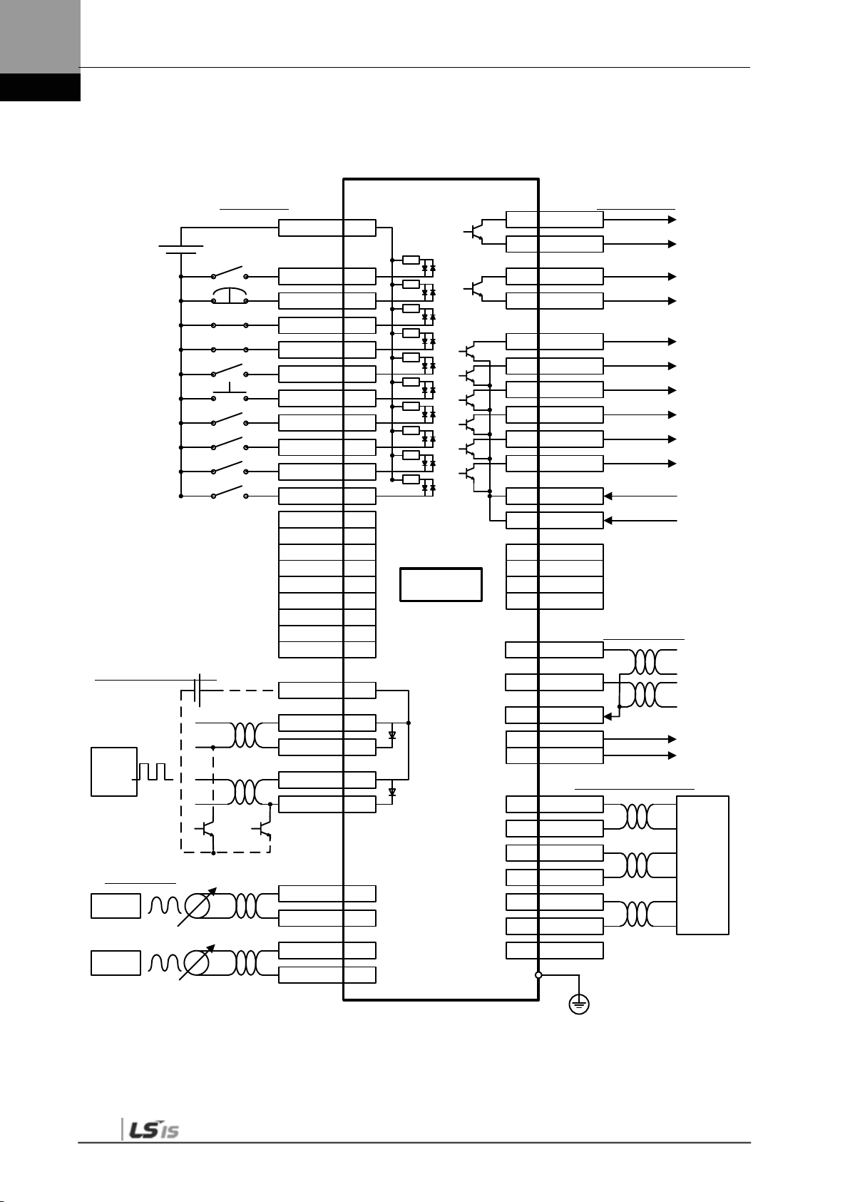
3.1.2 L7 Drive Block Diagram [L7SA008□ - L7SA035□]
NOTE 1) If you use a DC reactor, connect to the PO and PI pins.
NOTE 2) If you use external regenerative resistance, connect to the B+ and B pins after you remove the B
and BI short-circuit pins.
NOTE 3) The L7SA008□ and L7SA035□ models are c ooled by a DC 24 [V] cooling fan.
3-2

3. Wiring Method
Main Control
Diode
L3
Three-phase
L1
L2
Lamp
Chage
Output
Encoder
POWER Circuit Access(CN7)
DSP / FPGA
CN2
M
IGBT
W
Current Sensor
U
V
B
B+
E
PO
PI
(Note1)
C1
C2
S
M
P
S
T1
T2
Thermister
AC200~230V
CN5
CN3,CN4
BISS
FAN
(Note3)
USB TO UART
External Regenerative
Resistance(separately Installed)
(Note2)
Resistance
Regenerative
Power Input
Power Input
AC200~230V
One-phase
Main Power
Failure Detection
Circuit
Internal
Temperature
Detection
Circuit
Relay
Operation
Circuit
DC Voltage
Detection
Circuit
Regenerative
Braking
Operation
Circuit
IGBT
Temperature
Detection
Circuit
PWM
Signal
SC Detection
Circuit
U and V
Current
Detection
Circuit
DB
Operation
Circuit
RS422
Communication
USB
Communication
A/D Conversion
D/A Conversion
P/C Insulation I/F
Input
Encoder
Contact Output
(5 points)
(2 points)
Pulse Input
Contact Input
(10 points)
Monitor Output
(10 points)
Analog Input
(2 points)
Upper Level Controller Connection(CN1)
Control Power
Failure Detection
Circuit
Thermister
U,VCurrent
DC Voltage
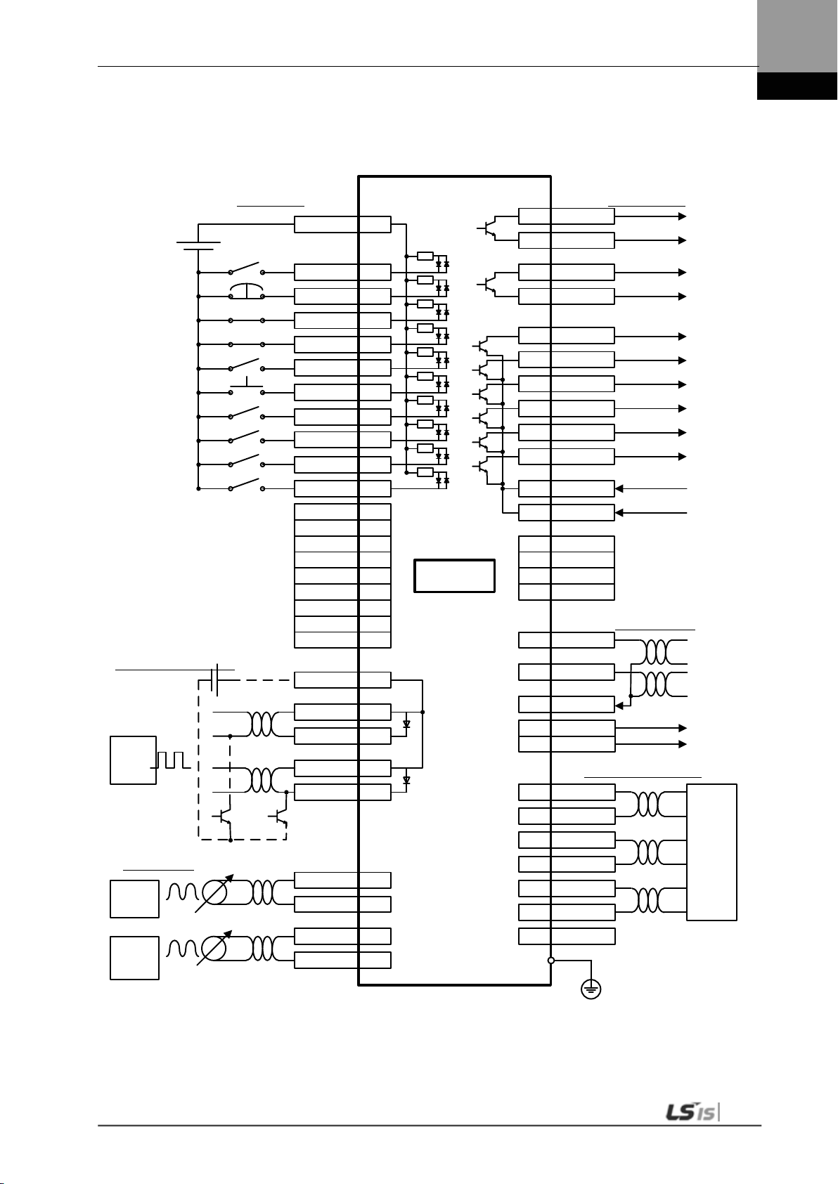
3.1.3 L7 Drive Block Diagram [L7SA050□ ]
NOTE 1) If you use a DC reactor, connect to the PO and PI pins.
NOTE 2) If you use external regenerative resistance, connect to the B+ and B pins after attac hing wires of
internal regener ative resistance to “NC” hole on the case.
NOTE 3) The L7SA050□ models are cooled by a DC 24 [V] cooling fan.
3-3
3. Wiring Method
U
V
W
L1
L2
L3
C1
C2
B+
B
BI
38
39
CN1
RA
M
E
Alarm-
Alarm+
1Ry
RA
1SK
1Ry1MC
+24V
NF
1MC
R S T
서보드라이브
(200~230V)
Main
OFF
Main
ON
인코더
외부
회생저항
주1)
주2)
PO
PI
DC 리액터
3.2 Power Wiring
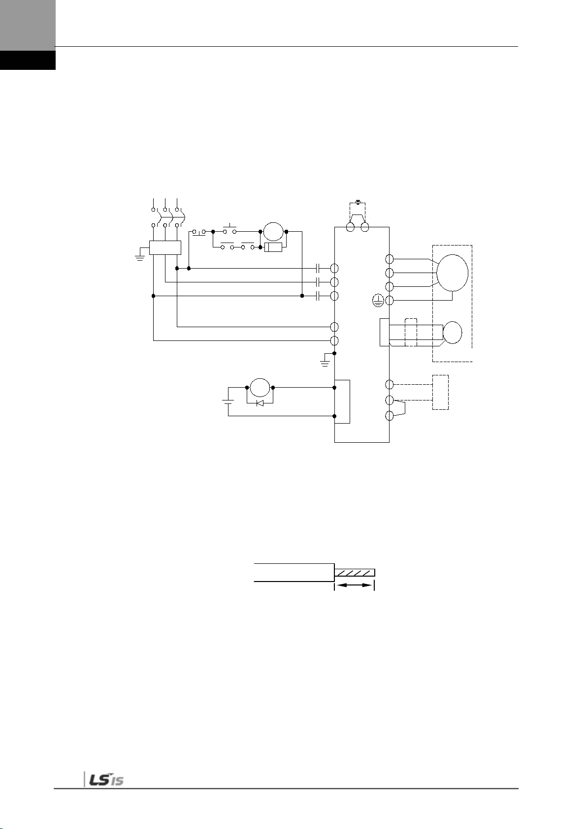
3.2.1 L7 Drive Wiring Diagram [L7SA001□ - L7SA035□]
Servo Drive
Note 1)
DC Reactor
Encoder
Note 2) External
Regenerative Resistancer
NOTE 1) It takes approximately one to two sec onds until alarm signal is output after you turn on the main
NOTE 2) Short-circuit B and BI terminals before use. Regenerative resistance of L7SA001□-L7SA004□
NOTE 3) Remove the sheath of cables to be used for the main circ uit power by approximately 7-10 [㎜] and
power. Accordingly, push and hold the main power ON switch for at least two seconds.
(50 [W], 100 [Ω]), L7SA010□ (100 [W], 40 [Ω]), and L7SA035□ (150 [W], 13 [Ω]) exist inside. If
regenerative capacity is high because of frequent acceleration and deceleration, open the shortcircuit pins ( B, BI) and connect external regenerative res istance to B and B+.
use devoted crim p terminals. (Refer to “3.2.2 Power Circuit Electric Sub Assembly Standards.”)
NOTE 4) Connect or remove the main circuit power unit wiring after pushing the button of t he L7SA001□ –
L7SA010□ drive terminal. For drive L7SA 035□, use a (-)slot screw drive for connecti on and
removal.
7~10㎜
3-4

3. Wiring Method
U
V
W
L1
L2
L3
C1
C2
B+
B
38
39
CN1
RA
M
E
Alarm-
Alarm+
1Ry
RA
1SK
1Ry
1MC
+24V
NF
1MC
R
S
T
(200~230V)
Main
OFF
Main
ON
Encoder
(Note1)
(Note2)
PO
PI
DC Reactor
external
regenerative
resistance
Servo Drive
3.2.2 L7 Drive Wiring Diagram [L7SA050□]
NOTE 1) It takes approximately one to two sec onds until alarm signal is output after you turn on the m ain
NOTE 2) Check status of connection of inter nal regenerative res istance(B+, B) before using because
power. Accordingly, push and hold the main power ON switch f or at least two seconds.
L7SA050□ (120[W], 6.8[Ω ]) has internal regenerative resis tance. If value of regener ative voltage
is too high by freq uent dec eler at i on an d ac cel er ati on, i ns tall exter nal r egen er ati ve res i stanc e on B,
B+ terminal after at taching internal regenerative resistance connected B+, B to “NC” hole on the
case.
3-5

3. Wiring Method
Name
L7SA001□
L7SA002□
L7SA004□
L7SA008□
L7SA010□
L7SA020□
L7SA035□
L7SA050□
3.2.3 Dimensions for Power Circuit Electrical Parts
MCCB(NFB)
Noise Filter
(NF)
DC reactor
MC
L1,L2,L3
PO,PI,N,
B+,B,BI
Wire
U,V,W
C1
C2
Crimp terminal
Regenerative
resistance
(Provided by
default)
Connector
(L1,L2...U,V,W
)
30A Frame 5A (ABE 33b/5)
AWG16(1.5 ㎟) AWG16(1.5 ㎟) AWG16(1.5 ㎟)
UA-F1510, SEOIL
(10 mm Strip & Twist)
30A Frame
10A
(ABE33b/10)
TB6-B010LBEI(10A) TB6-B030NBDC(30A)
HFN-10 (10 A) HFN-15 (15 A) HFN-30 (30 A)
11A / 240V
(GM□-9)
AWG16
(1.5 ㎟)
50 [W]
100 Ω
• BLF 5.08/03/180F SN BK BX
• BLF 5.08/11/180F SN BK BX
30A Frame 15A (ABE 33b/15) 30A Frame 30A (ABE33b/30)
18A / 240V
(GM□-18)
AWG14
(2.5 ㎟)
UA-F2010, SEOIL
(10 mm Strip & Twist)
100 [W]
40 Ω
• BLZ7.62HP/03/180LR
SN BK BX SO
BLZ7.62HP/11/180LR
SN BK BX SO
32A / 240V
(GM□-32)
AWG12
(4.0 ㎟)
UA-F4010, SEOIL(10 mm
Strip & Twist)
150 [W]
13 Ω
50A Frame
40A(ABE53b
/40)
TB6-
B040A(40A)
HFN-
40(40A)
50A / 240V
(GM□-50)
AWG10 (6.0
㎟)
AWG16(1.5
㎟)
GP110028
KET
120[W]
6.8Ω
Note1) Use 600V-PVC Insulated w ire for wiring.
Use appr oved UL wire(Temp. 60 ℃ or above) for UL(CSA) Regulation.
Use approved wire for any other r egulations.
Use equivalent or above componets compare to components above for any special applications.
3-6

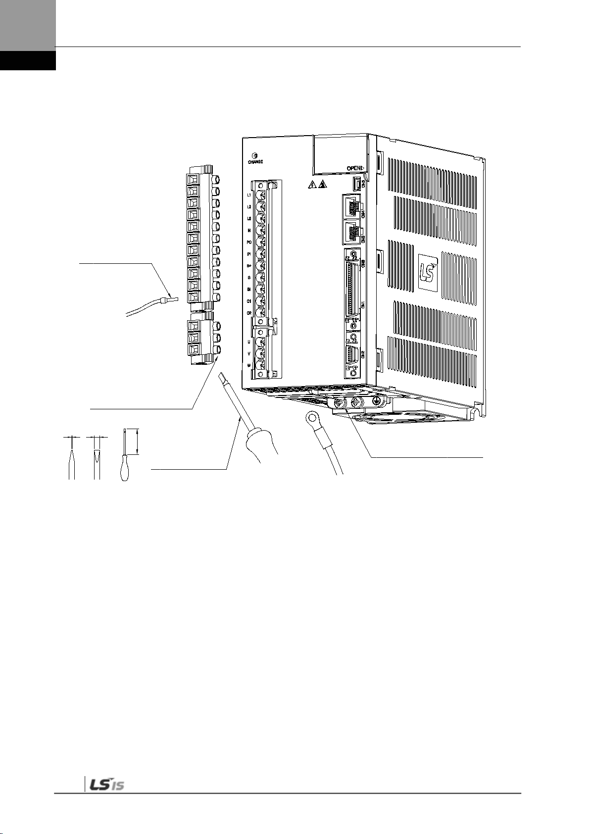
3. Wiring Method
0.6 3.5
100
A
B
C
0.4~0.5[N·m]
SD 0.6x3.5x100
0.4~0.5[N·m]
7~10[㎜]
7~10[㎜]
( L7SA004□ or below)
Length of strip
(L7SA008□ ~ L7SA010□)
Length of strip
Weidmueller’s
SD 0.6x3.5x100
M4 : 1.2[N·m]
Weidmueller’s
M4 : 1.2[N·m]
3-7
3. Wiring Method
A
B
C
0.4~0.5[N·m]
7~10[㎜]
(L7SA020□ ~ L7SA035□)
Length of strip
Weidmueller’s
SD 0.6x3.5x100
M4 : 1.2[N·m]
1) Refer to the drawings above for wiring with BLF 5.08 or BLZ 7.62HP Series connector.
2) Insert wire into wire-hole when upper screw is untightened and then, use appropriate (-) shaped
screwdriver with 0.4 ~ 0.5[N.m] torque to make tight completely.
3) Cut by vibration, malfunction or fire by short could be occurred if torque of screwing was not enough.
4) Make tight completely by using hooks both side when connectors are attached to servo drive after
wiring.
5) FG screw which is located the bottom of servo drive has to be M4 and put on the FG screw with
1.2[N.m] torque.
6) Malfunction of drive could be occurred if torque of screwing was not enough.
7) Recommended (-)shaped screwdriver : Weidmueller’s SD 0.6x3.5x100.
3-8

3. Wiring Method
Terminal Block Signals
TB1
TB2
TB3
NC : 내부 회생저항기
리드 단자 고정용 나사
NC : Internal regenerative resistor
Screw for holding lead terminal
(L7SA050□)
TB1
L1 L2 L3 B+ B U V W FG FG
TB2
N PO P1
TB3
C1 C2
Screw : M4
Screwing torque : 1.2[N·m]
Screw : M4
Screwing torque : 1.2[N·m]
Screw : M4
Screwing torque : 1.2[N·m]
1) Cut by vibration, malfunction or fire by short could be occurred if torque of screwing was not enough.
3-9

3. Wiring Method
establishment
rotation)
3.3 Timing Diagram
3.3.1 Timing Diagram During Power Input
For L7 Series, connect single-phase power to the C1 and C2 terminals to supply power to
the control circuit, and three-phase power to L1, L2, and L3 to supply power to the main
circuit.
The servo signal becomes Ready after the maximum time of 120 [ms] that is required to
reset the inside of the device. If you change the signal to ON, the servo starts operation in 40
[ms].
200 ms
Main power,
control power
supply
Control power
establishment 5
[V]
Control program
reset
Main power
Alarm
(Normally On)
Servo Ready
Servo On
Clear DB
150 ms
50 ms
120 ms
10 ms
10 ms
5 ms
PWM output
(motor
40 ms
2 ms
3-10

3. Wiring Method
Caution
200 ms
5 [V]
establishment
Alarm
Servo On
PWM
RESET
150 ms
40 ms
10 ms
5 ms
2 ms
30 ms
Alarm triggered by
Remove
causes that
3.3.2 Timing Diagram at the Time of Alarm Trigger
When the alarm triggers in the servo drive, PWM is blocked and the motor stops.
Never reset the alarm before you solve the problem that triggered the alarm and change the
command signal (Servo ON) to OFF.
Main power,
control power
supply
Control power
establishment
Control
program
Reset
Main power
(Normally On)
Servo RDY
Clear DB
(Motor rotation)
anomaly
triggered
alarm
3-11

3. Wiring Method
Caution
R2
Internal
Circuit
COM
R1
DC 24V
3.4 Control Signal Wiring
3.4.1 Contact Input Signal
1. There are two input contacts based on the characteristics of individual signals: contact A and
contact B. They can be set by [P2-08] and [P2-09].
2. It is possible to turn each contact on or off forcibly with [Cn-07]. Take extra caution, however,
because each contact is automatically turned off when power is off.
3. The signal definition of each contact can be modified by [P2-00], [P2-01], [P2-02], [P2-03], and
[P2-04].
R1: 3.3 KΩ, R2: 680 Ω
3-12
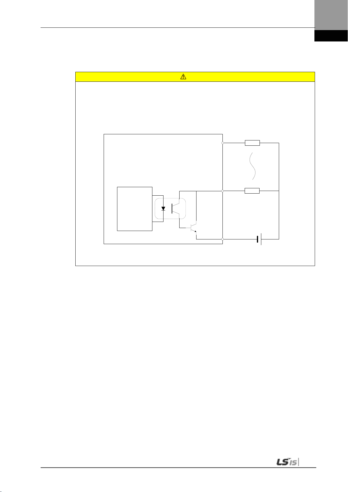
3. Wiring Method
Caution
Internal
Circuit
DC 24V
L
L
Contact
Contact
Note 1)
3.4.2 Contact Output Signal
1. There are two output contacts based on the characteristics of individual signals: contact A and
contact B. They can be set by [P2-10].
4. It is possible to turn each contact on or off forcibly with [Cn-08]. Take extra caution, however,
because each contact is automatically turned off when power is off.
5. The signal definition of each contact point can be modified by [P2-05], [P2-06], and [P2-07].
6. Overvoltage and overcurrent may cause damage because a transistor switch is used internally.
Rated voltage and current: DC 24 [V] ±10%, 120 [㎃]
NOTE 1) For alarm and ready output signals, the GND24 terminal is separated.
3-13

3. Wiring Method
Servo Drive
Input/output signal
AGND
AGND
Twisted Pair
Shield Wire
330 [Ω] 1/4 [W]
330 [Ω] 1/4 [W]
5 [kΩ]
0.1 [uF]
+12 [V] (34)
-
Analog command
(26), (27), (1)
AGND
(8)
3.4.3 Analog Input/Output Signals
1. Keep GND as 0 [V] of control power.
2. Keep the input signal command voltage within ±10 [V], and input impedance at 22 [㏀].
3. Output signal voltage for Monitor 1 (No. 28) and Monitor 2 (No. 29) is ±10 [V].
Input/output
FG
Configure wiring as shown in the following image when you adjust analog input with
parameter resistance by using power supplied by the drive.
Do not exceed the maximum output capacity of 30 [㎃].
3-14
12 [V] (35)
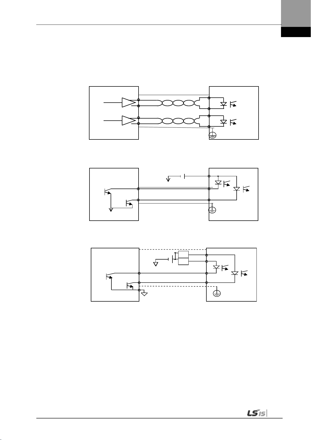
3. Wiring Method
Servo Drive
Upper
PF
PR
PF+
-
PR+
-
Line drive
Line receiver
Twisted Pair
Servo Drive
Upper
+24 [V]
GND24
GND24
Pulse COM
-
Shield Wire
-
Upper
Servo Drive
PR+
PF+
PF-
-
GND12
Power note 1)
NPN
R
R
3.4.4 Pulse Train Input Signal
(1) Line Driver (5 [V]) Pulse Input
level controller
Shield Wire
r
PF
PR
FG
(2) Open Collector (24 [V]) Pulse I nput
level controller
PF
PR
FG
(3) 12 [V] or 5 [V] NPN Open Collector Pulse Comm and
level controller
PR
FG
NOTE 1) When using 5 [V] power: Resistance R = 100-150 [Ω], 1/2 [W]
When using 12 [V] power: Resistance R = 560-680 [Ω], 1/2 [W]
When using 24 [V] power: Resistance R = 1.5 [kΩ], 1/2 [W]
3-15

3. Wiring Method
Servo Drive
Upper level controller
AO
/AO
GND
Line drive
Line receiver
GND
GND
Upper level controller
Servo Drive
Power
PNP
PF+
-
P
PR+
4
PR
R
R
(4) PNP Open Collector Pulse Command
note 2)
NOTE 1) When using 24 [V] power: Resistance R = 1.5 [kΩ], 1/2 [W]
When using 12 [V] power: Resistance R = 560-680 [Ω], 1/2 [W]
When using 5 [V] power: Resistance R = 100-150 [Ω], 1/2 [W]
3.4.5 Encoder Output Signal
Connect the GND terminal of the upper level controller and the GND terminal of CN1
because encoder signals are output based on the GND of control power.
Encoder signals for the servo motor received from CN2 are pre-scaled according to the ratio
defined by [P0-14] an d out put in lin e driver mode.
PF
-
FG
r
PA
rd
Set “1” on the 3
bit in the menu [P0-17] ‘Fuction Select Bit',
It outputs open collector A,B,Z phases through existing AL0, AL1 and AL2 contact points.
(Output voltage 40mA and below, Maximum frequency 100Khz)
3-16

3. Wiring Method
Encoder
1
2
3
4
5
6
7
8
9
10
11
12
13
14
15
A
/A
B
/B
Z
/Z
U
/U
V
/V
W
/W
5V
GND
SHD
13
12
11
10
9
8
5
6
3
4
1
2
14
7
Frame
Servo Drive
Servo Motor
AWG24 7Pair Twisted
Shield Wire
Cable
Connector
Maker -
AMP
172163-1
170361-1
Cable
Connector(CN2)
Maker – 3M
10314
-
52A
0-008
10114-
3000
VE
Servo Drive
Servo Motor
Encoder
A
B
C
D
E
F
K
L
M
N
P
R
H
G
J
A
/A
B
/B
Z
/Z
U
/
U
V
/V
W
/W
5V
GND
SHD
13
12
11
10
9
8
5
6
3
4
1
2
7
Frame
AWG24 7Pair Twisted
Shield Wire
Cable
Connector(CN2)
Maker – 3M
10314-52A0-008
10114-3000VE
Cable
Connector
MS
3108B20-29S
14
3.5 Quadrature Encoder Signaling Unit (CN2) Wiring
3.5.1 APCS-EAS Cable
3.5.2 APCS-EBS Cable
3-17

3. Wiring Method
Encoder
1
2
3
4
7
8
9
MA
SL
/SL
+5V
GND
SHD
3
4
5
6
14
7
Frame
Servo Drive
Servo Motor
AWG24 4Pair Twisted
Shield Wire
Cable
Connector
Maker - AMP
172161-1
170361-1
Cable
Connector(CN2)
Maker – 3M
10314-52A0-008
10114-3000VE
/MA
3.6 Serial Encoder Signaling Unit (CN2) Wiring
3.6.1 APCS-ECS Cable
3.6.2 APCS-EDS Ca bl e
3-18
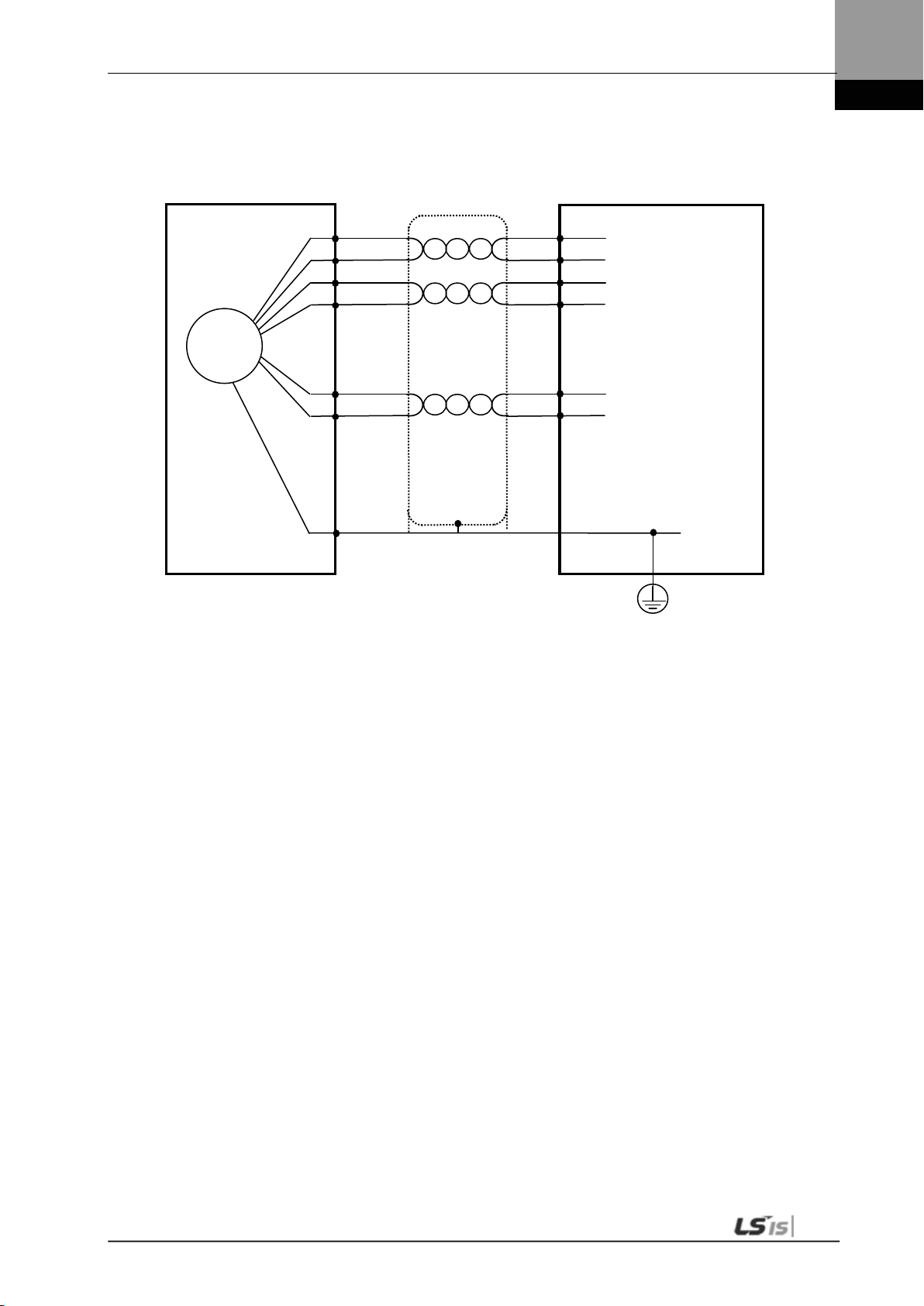
3. Wiring Method
Servo Dr i ve
Servo Motor
인코더
1
MA
Cable
Connector(CN2)
Maker
10314
10114
Connector
Tyco Connector
(7Ciruits)
Encoder
3
3.6.3 APCS-EES Ca ble
6
2
7
9
4
5
/MA
SL
/SL
5V
GND
SHD
4
5
6
14
7
Frame
- 3M
-52A0-008
-3000VE
3-19

3. Wiring Method
Servo Dr i ve
Servo
A
MA
AWG24 4Pair Twi st
Cable
Connector(CN2)
Maker
10314
10114
Cable
Connector
MS3108S20
E
3
1
MA
Cable
Connector(CN2)
Maker
10314
10114
Cable
Connector
MS3108S20
Encoder
3
AWG24 4Pair Twist
Servo
Servo
3.7 Multi Turn Encoder signal unit(CN2) wiring
3.7.1 APCS-ECS1 Cable
Motor
2
Shield Wire
3
4
5
6
7
8
-29S
9
3.7.2 APCS-EDS1 Cable
/MA
SL
/SL
BAT+
BAT-
5V
GND
SHD
4
5
6
14
7
Frame
Drive
- 3M
-52A0-008
-3000VE
3-20
ncode
Motor
-29S
B
C
D
E
F
H
G
J
Shield Wire
/MA
SL
/SL
BAT+
BAT-
5V
GND
SHD
4
5
6
14
7
Frame
- 3M
-52A0-008
-3000VE

3. Wiring Method
Servo Dr i ve
Servo Motor
인코더
1
MA
Cable
Connector(CN2)
Maker
10314
10114
Connector
Tyco Connector
Encoder
3
3.7.3 APCS-EES1 Cable
6
2
7
8
3
9
4
5
/MA
SL
/SL
BAT+
BAT_
5V
GND
SHD
4
5
6
14
7
Frame
- 3M
-52A0-008
-3000VE
3-21

3. Wiring Method
Absolute data
Pre
3.8 Transmission of Absolute Encoder Data
3.8.1 Transmission of Absolute Encoder Data
Upon the absolute encoder's request for absolute data, the data of the absolute encoder are
transmitted to the upper level controller in the form of quadrature pulses through the output
of the encoder output signals, AO and BO.
In this case, pulses are output at the speed of 500 [Kpps].
Among absolute data, multi-turn data are transmitted first, followed by single-turn data.
(Refer to “4.1.6 External Input Signal and Logic Definition" for information on the allocation of
the sequence input signal and ABS-RQ signal.)
Transmission Sequence of Absolute Data
1. When the servo is off, change the ABS_RQ signal on the upper level controller to ON.
2. The servo drive checks the ABS_RQ signal for 10 [ms].
3. The servo drive prepares the transmission of multi-turn data for 100 [ms].
4. The servo drive transmits multi-turn data for up to 140 [ms] (based on 16-bit multi-turn dat a) .
5. The servo drive prepares the transmission of single-turn data for 100 [ms].
6. The servo drive transmits single-turn data with the pre-scaler ratio applied for up to 1100 [ms]
(based on 19-bit single-turn data).
7. The servo drive operates with normal encoder output signals 100 [ms] after the single-turn data are
completely transmitted.
transmission
-scaler pulse output
3-22

4. Parameters
4. Parameters
4.1 How to Use the Loader
4.1.1 Names and Functions of Each Parts
Display 5-digit FN D data.
Digit 5 Digit 4 Di git 3 Digit 2 Digit 1
Displays the decimal point.
E.g.) 123.4
[MODE]: Change display mode.
[/LEFT]: Move to another data digit.
[UP]: Increase displayed data.
[DOWN]: Decr ease displayed data.
[SET]: Confirm displayed data.
[/RIGHT]: Move to another data digit.
In the case of 16 bits, the minus symbol is us ed.
In the case of 32 bits, a dot is used.
E.g.) -123.4
4-1

4. Parameters
①
②
4.1.2 Status Summary Display
(1) Status Summary Display in Speed Mode
Example of the OFF status of the servo in speed control mode
DIGIT 3-1: Displays the current status of the servo.
bb - Servo OFF
run - Servo ON
Pot - CCW Limit
not - CW Limit
DIGIT 4_High: ZSPD
DIGIT 4_Medium: INSPD or INPOS
DIGIT 4_Low: Command (speed or torque)
DIGIT 4_DOT: Ready
DIGIT 5: Displays the current control mode.
P - Position control
S - Speed control
T - Torque control
DIGIT 5_DOT: Servo ON
Example of the ON status of the servo in speed control mode
4-2

4. Parameters
Operation Status
Screen
Function
Notes
(2) Servo Operation Status Summary Display List
The following list explains the operation status summary display of different modes of the
servo.
Displays the servo's OFF status when in the
position mode.
Displays the servo's ON status when in position
mode.
Displays CCW status when in position mode.
Displays CW status when in position mode.
Displays the servo's OFF status when in speed
mode.
Displays the servo's ON status when in speed
mode.
Displays CCW status when in speed mode.
Displays CW status when in speed mode.
Displays the servo's OFF status when in torque
mode.
Displays the servo's ON status when in torque
mode.
Displays CCW status when in torque mode.
Displays CW status when in torque mode.
4-3

4. Parameters
St-
00
St-
01
St
-02
St
-24
St-
25
St-26
P0-00
P0-01
P0-02
P0-25
P0-26
P0-27
Cn-00
Cn-01
Cn-02
Cn-13
Cn-14
Cn-15
UP
DOWN
MODE
P4-00
P4-01
P4-02
P4-11
P4-12
P4-13
Operation Status
Summary Display
P1-00 P2-00 P3-00
P1-25 P2-22 P3-20
4.1.3 Parameter Handling
(1) Parameter Movement
Example of changing speed control mode to position control mode ([P0-03]: 00001 -> 00002)
If the alarm does not go off at the start of operation, the speed operation mode [S=bb] indi cating
operation status is displayed.
Editable parameters are from [P0-00] to [Cn-15]. Press [SET] when a parameter number is
displayed and you can see and edit the parameter data.
In the initial parameter edit status, the number on the far right flickers (ON and OFF for 0.5 seconds
respectively) and becomes editable.
4-4
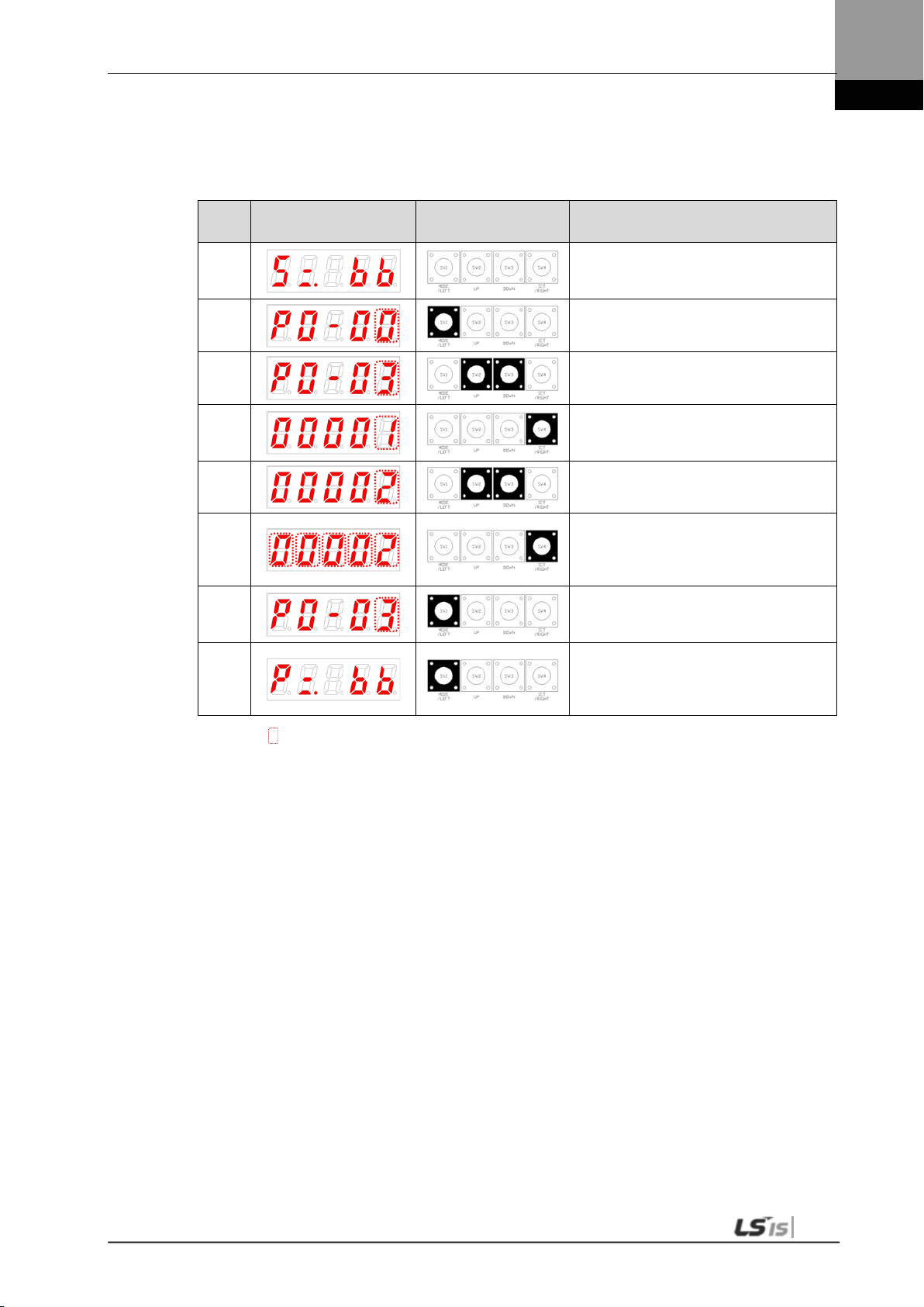
4. Parameters
Orde
r
Loader Displays
Keys to Use
What to Do
(2) Example of changing speed control mode to position control
mode ( [P0-03]: 00001 -> 00002 )
Displays the speed control mode with
1
2
main power and control power
permitted.
Press [MODE] to move to [P0-00].
3
4
5
6
7
8
NOTE 1) “ ” i ndicates flickering.
NOTE 2) If you hold down [UP] / [DOWN] at the current cursor in the parameter window, the number
continues to increase/decrease.
Press [UP] or [DOWN] to move to [P003].
Press [SET] to go to the parameter edit
window. The parameter is displayed as
00001.
Press [UP] or [DOWN] at the blinking
cursor to change the number to 00002.
Press and hold [SET] for approximately
one second. Af ter two flickers, the
number will be saved as 00002 in the
parameter.
Press and hold [MODE] for
approximately one second to return to
the P0-03 parameter.
Press [MODE] to change status to
position operation [P= bb] status which
is the summary display of the current
status.
4-5

4. Parameters
Orde
r
Loader Displays
Keys to Use
What to Do
(3) Example of changing speed proportional gain 2
([P1-07]: 200 [rad/s] -> 500 [rad/s])
Displays the speed control mode with
1
2
main power and control power
permitted.
Press [MODE] to move to [P1-00].
3
4
5
6
7
8
NOTE 1) “ ” i ndicates flickering.
NOTE 2) If you hold down [UP] / [DOWN] at the current cursor in the parameter window, the number
continues to increase/decrease.
Press [UP] or [DOWN] to move to [P107].
Press [SET] to enter parameter edit
mode. The parameter is displa y ed as
00200.
Press [/LEFT] or [/RIGHT] at the
blinking cursor to move to the desired
digit, DIGIT 3.
Press [UP] or [DOWN] at the blinking
DIGIT 3 position to c hange the number
to 00500.
Press and hold [SET] for approximately
one second. Af ter two flickers, the
number will be saved as 00500 in the
parameter.
Press and hold [MODE] for
approximately one second to return to
[P1-07].
4-6

4. Parameters
Orde
r
Loader Displays
Keys to Use
What to Do
(4) Example of changing DAC output offset 1 ([P0-19]: 0 [Unit/V] ->
-500 [Unit/V])
Displays the speed control mode with
1
2
main power and control power
permitted.
Press [MODE] to move to [P0-00].
3
4
5
6
7
8
NOTE 1) “ ” i ndicates flickering.
NOTE 2) If you hold down [UP] / [DOWN] at the current cursor in the parameter window, the number
continues to increase/decrease.
Press [UP] or [DOWN] to move to [P019].
Press [SET] to enter parameter edit
mode. The parameter is dis pla y ed as
00000.
Press [/LEFT] or [/RIGHT] at the
blinking cursor to move to the desired
digit, DIGIT 3.
Press [UP] or [DOWN] at the blinking
DIGIT 3 position to c hange the number
to -0500.
Press and hold [SET] for approximately
one second. Af ter two flickers, the
number will be saved as -0500 in the
parameter.
Press and hold [MODE] for
approximately one second to return to
[P0-19].
4-7

4. Parameters
4.1.4 Data Display
(1) Binary
① Minimum (0b00000) ② Ma xim um (0b11111)
(2) Hex
① Minimum (0x0000) ② Maximum (0xFFFF)
(3) 16-bit Unsigned Integer
① E.g.) 0 ② E.g.) +1234
(4) 16-bit Signed Integer
① E. g.) -1234 ② E.g.) +5678
① E.g.) -1234 ② E.g.) +5678
(5) 16-bit Decimal Point Display
① E. g.) -123.4 ② E.g.) +123.4
① E.g.) -123.4 ② E.g.) +123.4
4-8

4. Parameters
①
②
Order
Loader Displays
Keys to Use
What to Do
(6) 32-bit Signed Integer Data Display
Minimum (-2147483648)
Display upper two digits Display middle four digits Display lower four digits
Maximum (2147483647)
Display upper two digits Display middle four digits Display lower four digits
E.g.) [St-16]: Displayed as Upper = 0, Middle = 0012, and
Lower = 2071
1
2
3
4
5
6
7
NOTE 1) “ ” i ndicates flickering.
Displays the speed control mode with
main power and control power
permitted.
Press [MODE] to move to [St-00].
Press [UP] or [DOWN] to move to [St16].
Press [SET] to display lower digit data.
Each time you press [/LEFT] or
[/RIGHT]
lower, middle, and upper data is
displayed.
Each time you press [/LEFT] or
[/RIGHT]
lower, middle, and upper data is
displayed.
Press and hold [MODE] for
approximately one second to return to
[St-16].
4-9

4. Parameters
Number
(A)
(9)
(8)
(7)
(6)
(5)
(4)
(3)
(2)
(1)
Contact
Number
DIA
DI9
DI8
DI7
DI6
DI5
DI4
DI3
DI2
DI1
4.1.5 External Input Contact Signal Display [St-14]
You can check whether the ON/OFF status of digital input/output signals that access the
servo drive are on or off.
(1) External Input Signal Display
The positions of the seven segment LEDs and CN1 connector pins correspond as follows.
If an LED that corresponds to a pin is turned on/off, it indicates ON/OFF accordingly.
Input Contact Display
CN1
Pin number
Allocated
default
Signal name
48 18 19 20 46 17 21 22 23 47
STOP EMG CWLIM
CCWLI
M
DIR
ALMR
ST
SPD3 SPD2 SPD1 SVON
4-10

4. Parameters
Input Signal
Input Allocation Number
4.1.6 External Input Signal and Logic Definition
The following describes how to allocate input signals and how to view them.
(1) Input Signal Allocation
L7 Drive allows for the allocation of a total of 19 input contact fuctions to 10 hardware
contacts.
Each of the input contact functions is located at the designated digit of parameter [P2-00],
[P2-01], [P2-02], [P2-03], or [P2-04]. Changing the value of the digit allows allocation to pins
DI1 through DIA
The default input signal allocation is as follows:
One number can be allocated to two input signals such as N (input signal): 1 (input allocation
number).
E.g.) If SVON and SPD1 are allocated to DI #01, you can use both the SVON signal and the
SPD1 signal when entering DI #01.
4-11

4. Parameters
Signal Name
Parameter
Allocation
Servo ON
[P2-00].Set Digit 1
Multi-speed 1
[P2-00]. Set Digit 2
Multi-speed 2
[P2-00]. Set Digit 3
Multi-speed 3
[P2-00]. Set Digit 4
Alarm reset
[P2-01]. Set Digit 1
Select rotation
direction
prohibited
prohibited
Stop
ratio 1
ratio 2
modes
[P2-01]. Set Digit 2
Forward rotation
[P2-01]. Set Digit 3
Reverse rotation
[P2-01]. Set Digit 4
Emergency stop
[P2-02]. Set Digit 1
[P2-02]. Set Digit 2
Electronic gear
[P2-02]. Set Digit 3
Electronic gear
[P2-02]. Set Digit 4
P control action
[P2-03]. Set Digit 1
Select gain 2
[P2-03]. Set Digit 2
Error pulse clear
[P2-03]. Set Digit 3
Torque limit
[P2-03]. Set Digit 4
Change operation
[P2-04]. Set Digit 1
Absolute encoder
data request
[P2-04]. Set Digit 2
Zero clamp
[P2-04]. Set Digit 3
Input
Signal
SVON F A 9 8 7 6 5 4 3 2
SPD1 F A 9 8 7 6 5 4 3
SPD2 F A 9 8 7 6 5 4
SPD3 F A 9 8 7 6 5
ALMRST F A 9 8 7 6
DIR F A 9 8 7
CCWLIM F A 9 8
CWLIM F A 9
EMG F A
STOP F
EGEAR1 F A 9 8 7 6 5 4 3 2 1
EGEAR2 F A 9 8 7 6 5 4 3 2 1
PCON F A 9 8 7 6 5 4 3 2 1
GAIN2 F A 9 8 7 6 5 4 3 2 1
P_CLR F A 9 8 7 6 5 4 3 2 1
T_LMT F A 9 8 7 6 5 4 3 2 1
MODE F A 9 8 7 6 5 4 3 2 1
ABS_RQ F A 9 8 7 6 5 4 3 2 1
ZCLAMP F A 9 8 7 6 5 4 3 2 1
Alwa
ys
Alloc
48 18 19 20 46 17 21 22 23 47
ated
A 9 8 7 6 5 4 3 2 1 0
CN1 Pin Default Allocation Number
2 1 0
3 2 1 0
4 3 2 1 0
5 4 3 2 1 0
6 5 4 3 2 1 0
7 6 5 4 3 2 1 0
8 7 6 5 4 3 2 1 0
9 8 7 6 5 4 3 2 1 0
No
Alloc
ation
1 0
Input
Signal
Definition
[P2-00] 0x4321
[P2-01] 0x8765
[P2-02] 0x00A9
0
0
0
0
[P2-03] 0x0000
0
0
0
[P2-04] 0x0000
0
0
Default
setting
NOTE 1) No CN1 connector pin is allocated when the default value is " 0" .
4-12

4. Parameters
Input Signal
Input Allocation Number
(2) Example of Changing Input Signal A llocation
The input signal definition can be changed in [P2-00], [P2-01], [P2-02], [P2-03], and [P2-04].
The input signal logic definition can be changed in [P2-08] and [P2-09].
Allocate input signals as shown in the following table:
4-13

4. Parameters
Signal Name
Parameter
Allocation
Servo ON
[P2-00].Set Digit 1
Multi-speed 1
[P2-00]. Set Digit 2
Multi-speed 2
[P2-00]. Set Digit 3
Multi-speed 3
[P2-00]. Set Digit 4
Alarm reset
[P2-01]. Set Digit 1
Select rotation
direction
prohibited
prohibited
Stop
ratio 1
ratio 2
modes
[P2-01]. Set Digit 2
Forward rotation
[P2-01]. Set Digit 3
Reverse rotation
[P2-01]. Set Digit 4
Emergency stop
[P2-02]. Set Digit 1
[P2-02]. Set Digit 2
Electronic gear
[P2-02]. Set Digit 3
Electronic gear
[P2-02]. Set Digit 4
P control action
[P2-03]. Set Digit 1
Select gain 2
[P2-03]. Set Digit 2
Error pulse clear
[P2-03]. Set Digit 3
Torque limit
[P2-03]. Set Digit 4
Change operation
[P2-04]. Set Digit 1
Absolute encoder
data request
[P2-04]. Set Digit 2
Zero clamp
[P2-04]. Set Digit 3
Input
Signal
SVON F A 9 8 7 6 5 4 3 2
SPD1 F A 9 8 7 6 5 4 3
SPD2 F A 9 8 7 6 5 4
SPD3 F A 9 8 7 6 5 4 3 2 1
ALMRST F A 9 8 7 6
DIR F A 9 8 7
CCWLIM F A 9 8
CWLIM F A 9 8 7 6 5 4 3 2 1
EMG F A 9 8 7 6 5 4 3 2 1
STOP F A 9
EGEAR1 F A 9 8 7 6 5 4 3 2 1
EGEAR2 F A 9 8 7 6 5 4 3 2 1
PCON F A 9 8 7 6 5 4 3 2 1
GAIN2 F A 9 8 7 6 5 4 3 2 1
P_CLR F A 9 8 7 6 5 4 3 2 1
T_LMT F A
MODE F
ABS_RQ F A 9 8 7 6 5 4 3 2 1
ZCLAMP F A 9 8 7 6 5 4 3 2 1
Alwa
ys
Alloc
48 18 19 20 46 17 21 22 23 47
ated
A 9 8 7 6 5 4 3 2 1 0
CN1 Pin Default Allocation Number
2 1 0
3 2 1 0
5 4 3 2 1 0
6 5 4 3 2 1 0
7 6 5 4 3 2 1 0
8 7 6 5 4 3 2 1 0
9 8 7 6 5 4 3 2 1 0
No
Alloc
ation
1 0
Input
Signal
Definition
[P2-00] 0x0321
0
[P2-01] 0x0765
0
0
[P2-02] 0x0080
0
0
0
0
[P2-03] 0x9000
0
[P2-04] 0x000A
0
0
Value
After
Changing
NOTE 1) No CN1 connector pin is allocated when the default value is " 0".
4-14
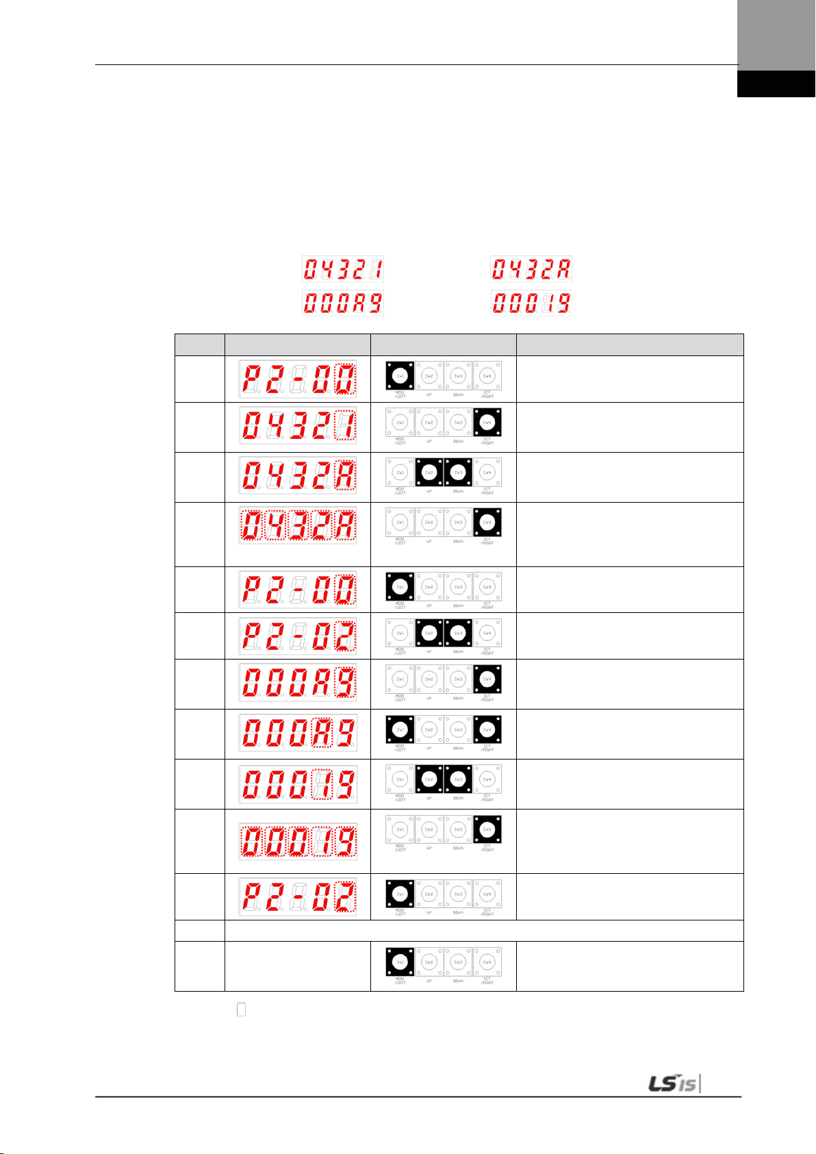
4. Parameters
Order
Loader Displays
Keys to Use
What to Do
Examples of Changing Input Signal Allocation
The following is an example of changing input signal allocation.
The allocation signals of SVON (CN1-47) and STOP (CN1-48) can be switched in the
following sequence.
Before Changing After Changing
[P2-00]:
[P2-02]:
1
2
3
4
5
6
7
8
9
10
11
Press [MODE] to move to [P2-00].
Press [SET] to enter parameter edit
mode. The parameter is displa y ed as
04321.
Press [UP] or [DOWN] at the blinking
cursor to change the number to
0432A.
Hold down [SET] for approximately
one second. Af ter two flickers, the
number is saved as 0432A for the
parameter.
Hold down [MODE] for approximately
one second to return to [P2-00].
Press [UP] or [DOWN] at the blinking
cursor to change the number to P2-02.
Press [SET] to enter parameter edit
mode. The parameter is displa y ed as
000A9.
Press [/LEFT] or [/RIGHT] at the
blinking cursor to move to the desired
digit, DIGIT 2.
Press [UP] or [DOWN] at the blinking
cursor to change the number to
00019.
Hold down [SET] for approximately
one second. Af ter two flickers, the
number is saved as 00019 for the
parameter.
Hold down [MODE] for approximately
one second to return to [P2-02].
12 ** Modification is not possible with the servo on &. Reset the parameter.
In case of exiting
※
NOTE 1) “ ” i ndicates flickering.
without saving the set
value
Hold down [MODE] for approximately
one second to return to the parameter.
4-15
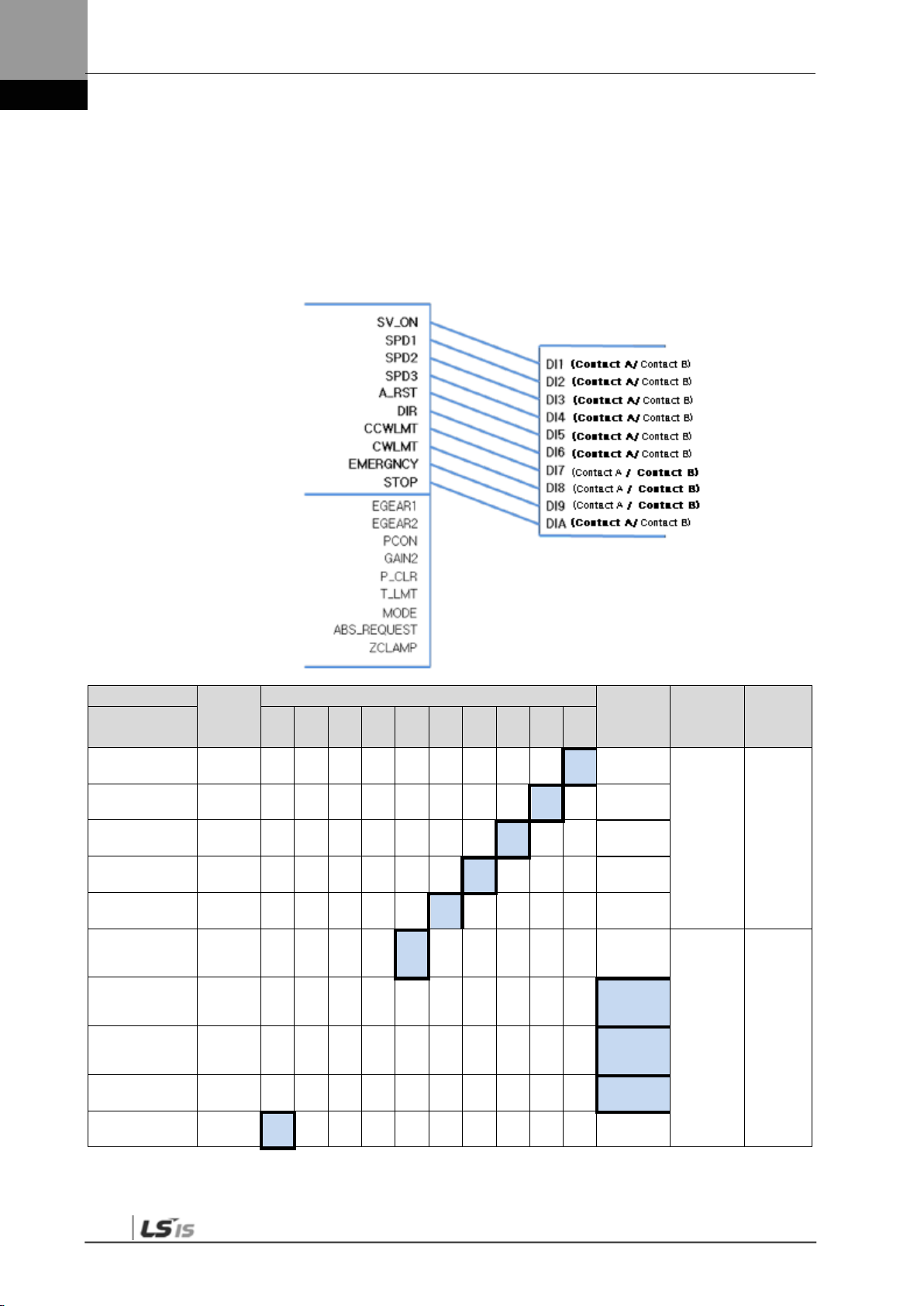
4. Parameters
Input signal lo
Input signal logic definition number
(3) Input signal logic definition
L7 Drive allows for defining the logic of input signals for 10 hardware contacts from DI1 to
DIA through parameters [P2-08] and [P2-09].
The logic of input signals as set in the factory is as follows.
gic definition
Signal Name Input
Parameter
Allocation
Servo ON
[P2-08].Set Digit 1
Multi-speed 1
[P2-08]. Set Digit 2
Multi-speed 2
[P2-08]. Set Digit 3
Multi-speed 3
[P2-08]. Set Digit 4
Alarm reset
[P2-08]. Set Digit 5
Select rotation
direction
prohibited
prohibited
Stop
[P2-09]. Set Digit 1
Forward rotation
[P2-09]. Set Digit 2
Reverse rotation
[P2-09]. Set Digit 3
Emergency stop
[P2-09]. Set Digit 4
[P2-09]. Set Digit 5
Signal
(Initial
name)
SVON
SPD1
SPD2
SPD3
ALMRST
DIR
CCWLIM
CWLIM
EMG
STOP
48 18 19 20 46 17 21 22 23 47
1 0
CN1 Pin Default Allocation Number
1 0
1 0
1 0
1 0
1 0
Contact B
1 0
Input
signal
logic
setting
[P2-08] 0x11111
0
0
0
[P2-09] 0x10001
Default
setting
NOTE 1) For the purpose of the input signal logic definitions, Contact A is 1 and Contact B is 0.
4-16
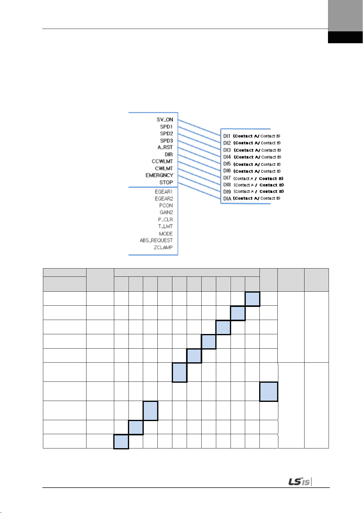
4. Parameters
Input signal logic definition
(4) Example of Changing Input Signal Logic Definitions
Input signal logic definitions can be changed in [P2-08] and [P2-09].
When input signals are allocated as below, settings will be done as shown in table below.
Input signal logic definition number
Signal Name
Parameter
Allocation
Servo ON
[P2-08].Set Digit 1
Multi-speed 1
[P2-08]. Set Digit 2
Multi-speed 2
[P2-08]. Set Digit 3
Multi-speed 3
[P2-08]. Set Digit 4
Alarm reset
[P2-08]. Set Digit 5
Select rotation
direction
[P2-09]. Set Digit 1
Forward rotation
prohibited
[P2-09]. Set Digit 2
Reverse rotation
prohibited
[P2-09]. Set Digit 3
Emergency stop
[P2-09]. Set Digit 4
Stop
[P2-09]. Set Digit 5
Input
Signal
SVON
SPD1
SPD2
SPD3
ALMRST
DIR
CCWLIM
CWLIM
EMG
STOP
48 18 19 20 46 17 21 22 23 47
1 0
CN1 Pin Default Allocation Number
Cont
act B
1 0
1 0
1 0
1 0
1 0
1 0
1 0
1 0
Input
signal
logic
definition
[P2-08] 0x11111
0
[P2-09] 0x11101
Default
setting
4-17
NOTE 1) For the purpose of the input signal logic definition, C ontact A is 1 and Contact B is 0.

4. Parameters
Order
Loader Displays
Keys to Use
What to Do
Examples of changing input signal logic defini tions
The table below shows examples of changing input signal logic definitions.
The sequence of changing logic signal contact A of SVON (CN1-47) to contact B and logic
signal contact B of CCWLIM (1-20) to contact A is as follows.
Before changing After changing
[P2-08]:
[P2-09]:
1
2
3
4
5
6
7
8
9
Press [UP] or [DOWN] at the blinking
cursor to move to [P2-08].
Press [SET] to enter parameter edit
mode. The parameter is displa y ed as
11111.
Press [UP] or [DOWN] at the blinking
cursor to change the number to 11110.
Hold down [SET] for approximately
one second. Af ter two flickers, the
number is saved as 11110 for the
parameter.
Hold down [MODE] for approximately
one second to return to [P2-08].
Press [UP] or [DOWN] at the blinking
cursor to change the number to [P209].
Press [SET] to enter parameter edit
mode. The parameter is displa y ed as
10001.
Press [/LEFT] or [/RIGHT] at the
blinking cursor to move to the desired
digit, DIGIT 2.
Press [UP] or [DOWN] at the blinking
cursor to change the number to 10011.
4-18
10
11
12 ** Modification is not possible with the servo on &. Reset the parameter.
In case of exiting
※
NOTE 1) “ ” i ndicates flickering.
without saving the set
value
Hold down [SET] for approximately
one second. Af ter two flickers, the
number is saved as 10011 for the
parameter.
Hold down [MODE] for approximately
one second to return to [P2-09].
Hold down [MODE] for approximately
one second to return to the parameter.
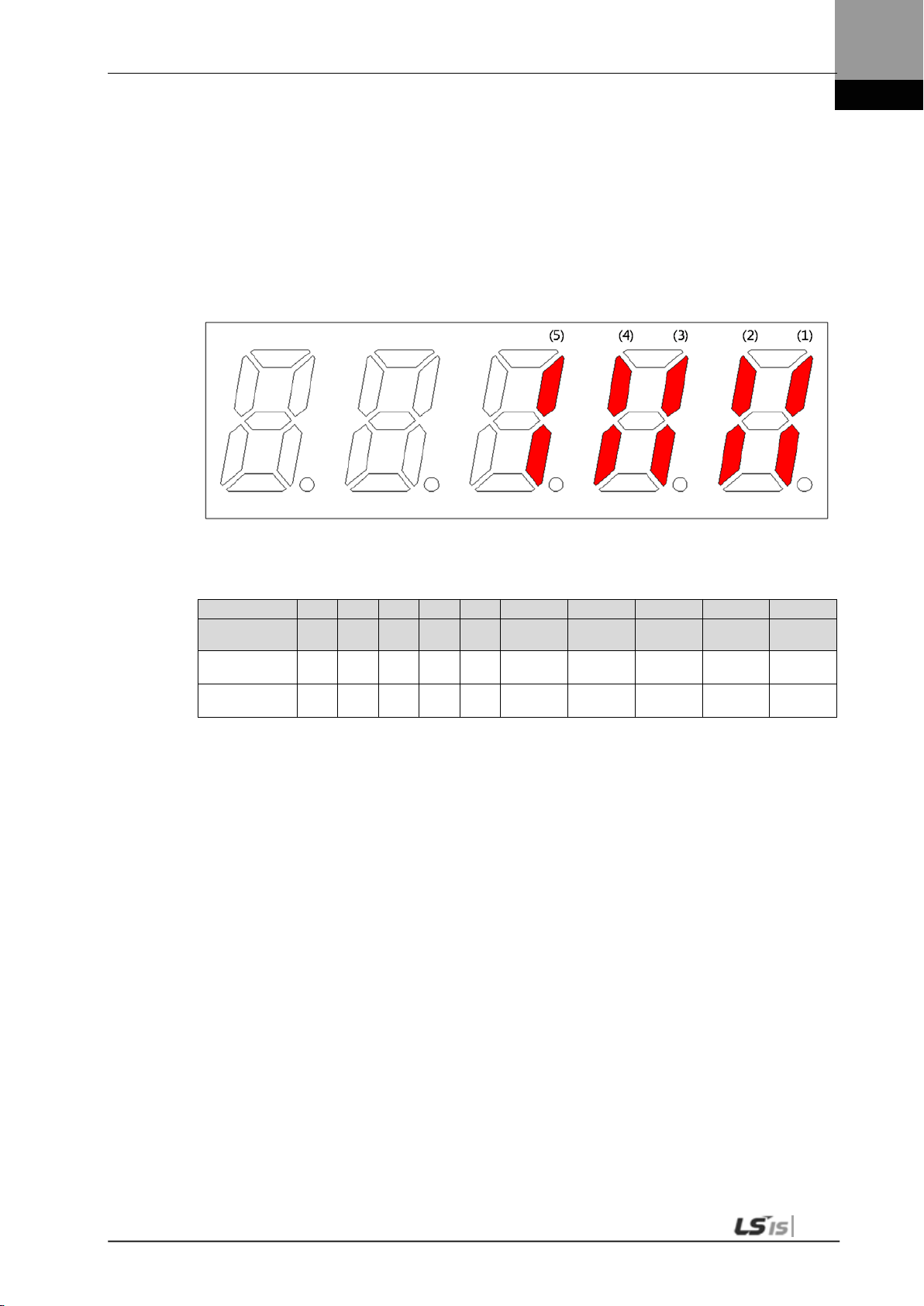
4. Parameters
4.1.7 External Output Contact Signal Display [St-15]
You can check whether the ON/OFF status of digital input/output signals that access the
servo drive are on or off.
(1) External Output Signal Display
The positions of the seven segment LEDs and CN1 connector pins correspond as follows.
If an LED that corresponds to a pin is turned on/off, it indicates ON/OFF accordingly.
Output Contact Display
Number (5) (4) (3) (2) (1)
Contact
Number
CN1
pin number
Allocated default
signal name
DO5 DO4 DO3 DO2 DO1
45 44 43 40/41 38/39
INPOS BRAKE ZSPD READY ALARM
4-19

4. Parameters
Output Signal
Output Allocation Number
4.1.8 External Output Signal and Logic Definition
The following explains output signal allocation and the method of checking allocation status.
(1) Output Signal Allocation
Output signal definition: [P2-05], [P2-06], [P2-07]
Output signal logic definition: [P2-10]
The default output signal allocation is as follows:
Signal Name
Parameter Allocation 45 44 43 40/41 38/39
Alarm
[P2-05].Set Digit 1
Servo Ready
[P2-05]. Set Digit 2
Zero speed achieved
[P2-05]. Set Digit 3
Brake
[P2-05]. Set Digit 4
Position reached
[P2-06]. Set Digit 1
Torque limit reached
[P2-06]. Set Digit 2
Speed limit reached
[P2-06]. Set Digit 3
Speed achieved
[P2-06]. Set Digit 4
Warning
[P2-07]. Set Digit 1
Output
Signal
ALARM F 5 4 3 2
READY F 5 4 3
ZSPD F 5 4
BRAKE F 5
INPOS F
TLMT F 5 4 3 2 1
VLMT F 5 4 3 2 1
INSPD F 5 4 3 2 1
WARN F 5 4 3 2 1
Alwa
ys
Alloc
ated
CN1 Pin Default Allocation Number
2 1 0
3 2 1 0
4 3 2 1 0
5 4 3 2 1 0
NOTE 1) No CN1 connector pin is allocated when the default value is " 0" .
Not
Alloc
ated
1 0
0
0
0
0 [P2-07] 0x0000
Internal
Parameter
[P2-05] 0x4321
[P2-06] 0x0005
Default
Value
4-20

4. Parameters
Output Signal
Output Allocation Number
(2) Examples of Changing Output Signal Allocati on
The output signal definition can be changed in [P2-05], [P2-06], and [P2-07].
The output signal logic definition can be changed in [P2-10].
Allocate output signals as in the following table:
Signal Name
Parameter Allocation 45 44 43 40/41 38/39
Alarm
[P2-05].Set Digit 1
Servo Ready
[P2-05]. Set Digit 2
Zero speed achieved
[P2-05]. Set Digit 3
Brake
[P2-05]. Set Digit 4
Position reached
[P2-06]. Set Digit 1
Torque limit reached
[P2-06]. Set Digit 2
Speed limit reached
[P2-06]. Set Digit 3
Speed achieved
[P2-06]. Set Digit 4
Warning
[P2-07]. Set Digit 1
Output
Signal
ALARM F 5 4 3 2
READY F 5 4 3 2 1
ZSPD F 5 4
BRAKE F 5 4 3 2 1
INPOS F 5 4 3 2 1
TLMT F 5 4 3 2 1
VLMT F 5
INSPD F
WARN F 5 4 3
Alwa
ys
Alloc
ated
CN1 Pin Default Allocation Number
3 2 1 0
4 3 2 1 0
5 4 3 2 1 0
2 1 0 [P2-07] 0x0002
Not
Alloc
ated
1 0
0
0
0
0
Internal
Parameter
[P2-05] 0x0301
[P2-06] 0x5400
Changing
Value
After
4-21
NOTE 1) No CN1 connector pin is allocated when the default value is " 0" .

4. Parameters
Order
Loader Window Display
Result
Keys to Use
What to Do
Example of Changing Output Signal Allocation
The following is an example of output signal allocation change.
The sequence of switching the allocation signals of ALARM (CN1-38/39) and ZSPD (CN1-
43) is as follows:
Before Changing After Changing
[P2-05]:
1
2
3
4
5
6
7
8 ** Modification is not possible with the servo on & Reset the parameter.
※
In case of exiting without
saving the set value
Press [MODE] to move to [P2-05].
Press [SET] to enter parameter
edit mode. The parameter is
displayed as 04321.
Press [UP] or [DOWN] at t he
blinking cursor to change the
number to 04323.
Press [/LEFT] or [/RIGHT] at the
blinking cursor to move to the
desired digit, DIGIT 3.
Press [UP] or [DOWN] at the
blinking cursor to change the
number to 04123.
Hold down [SET] for approximately
one second. Af ter two flickers, the
number will be saved as 04123 for
the parameter.
Hold down [MODE] for
approximately one second to
return to [P2-05].
Hold down [MODE] for
approximately one second to
return to the parameter.
4-22
NOTE 1) “ ” i ndicates flickering.
If two output signals are allocated to a number, the output contact setting error [AL-72] alarm
will be triggered.

4. Parameters
Output signal logic definition number
Output signal logic definitions
DO1(Contact A/Contact B)
DO2(
DO3(
DO4(
DO5(
(3) Output Signal Logic Definiti on
Output signal logic definition: [P2-10]
The logic of output signals as shipped from the factory is as follows.
Contact A/Contact B)
Contact A/Contact B)
Contact A/Contact B)
Contact A/Contact B)
Signal Name
Parameter Allocation 45 44 43 40 /41 38 /39
Alarm
[P2-10].Set Digit 1
Servo Ready
[P2-10]. Set Digit 2
Zero speed achieved
[P2-10].Digit 3
Brake
[P2-10].Digit 4
Position reached
[P2-10].Digit 5
Input
Signal
(Initial
Name)
ALARM
READY
ZSPD
BRAKE
INPOS
CN1 Pin Default Allocation Number
1 0
1 0
1 0
Contact B
0
0
Output
Signal
Logic
Definition
[P2-10] 0x10110
Default
Setting
NOTE 1) For the purpose of the input signal logic definition, C ontact A is 1 and Contact B is 0
4-23

4. Parameters
Output signal logic definitions
Output signal logic definition number
DO1(Contact A/Contact B)
DO2(
DO3(
DO4(
DO5(
(4) Examples of Changing Output Singal Logic Definition
Output signal logic definitions can be changed at [P2-10]
Set output singals as shown in the table below when they are allocated as below.
Contact A/Contact B)
Contact A/Contact B)
Contact A/Contact B)
Contact A/Contact B)
Signal Name
Parameter Allocation 45 44 43 40 /41 38 /39
Alarm
[P2-10].Set Digit 1
Servo Ready
[P2-10]. Set Digit 2
Zero speed achieved
[P2-10].Digit 3
Brake
[P2-10].Digit 4
Position reached
[P2-10].Digit 5
Input
Signal
(Initial
Name)
ALARM
READY
ZSPD
BRAKE
INPOS
CN1 Pin Default Allocation Number
1 0
1 0
1 0
1 0
Contact B
0
Output
Signal
Logic
Definition
[P2-10] 0x11110
Default
Setting
For the purpose of the input signal logic definition, Contact A is 1 and Contact B is 0
4-24

4. Parameters
Order
Loader Window Display
Result
Keys to Use
What to Do
Example of Changing Output Signal Allocation
The following is an example of output signal allocation change.
The sequence of switching the allocation signals of ALM (CN1-38/39) and ZSPD (CN1-43) is
as follows:
Before Changing After Changing
[P2-05]:
1
2
3
4
5
6
7
8 ** Modification is not possible with the servo on & Reset the param eter.
※
In case of exiting without
saving the set value
Press [MODE] to move to [P2-05].
Press [SET] to enter parameter
edit mode. The parameter is
displayed as 04321.
Press [UP] or [DOWN] at t he
blinking cursor to change the
number to 04323.
Press [/LEFT] or [/RIGHT] at the
blinking cursor to move to the
desired digit, DIGIT 3.
Press [UP] or [DOWN] at the
blinking cursor to change the
number to 04123.
Hold down [SET] for approximately
one second. Af ter two flickers, the
number will be saved as 04123 for
the parameter.
Hold down [MODE] for
approximately one second to
return to [P2-05].
Hold down [MODE] for
approximately one second to
return to the parameter.
4-25
NOTE 1) “ “ i ndicates flickering.
If two output signals are allocated to a number, the output contact setting error [AL-72] alarm
will be triggered.

4. Parameters
Move to
Another
Parameter
Parameter
Number
Initial Screen
Parameter
Group Name
Details
4.2 Parameter Description
4.2.1 Parameter System
There are a total of eight groups of parameters. Each group is explained in the following
table:
E.g.) In speed mode
-
Status Summary
Display
Displays the status
summary of the servo.
Displays the operation
status of the servo.
Saves system
configuration
information.
Save control-related
parameters.
Saves parameters
related to analog and
digital input/output.
Saves speed
operation parameters.
Saves position pulse
operation parameters.
Performs operation
handling.
MODE Key
St-00 - St-26
P0-00 - P0-27
P1-00 - P1-29
P2-00 - P2-22
P3-00 - P3-20
P4-00 - P4-14
Cn-00 - Cn-18
Status
System
Control
IN / OUT
Speed
Operation
Position
Operation
Command
The following explains the acronyms related to application mode in the parameter.
P: Use in position control m ode.
4-26
S: Use in speed control mode.
T: Use in torque control mode.
Press [MODE] once to move to the next display mode.

4. Parameters
4.2.2 Operation Status Display Parameter
For detailed information, refer to "4.3 Operation Status Display."
“**” Modification is not possible with the servo on & Power reset parameter.
“*” Parameter that cannot be modified with the servo on
Parameter Unit Initial
Details
Code Name Minimum Maximum
St-00
St-01
St-02
St-03
St-04
St-05
St-06
St-07
St-08
Current operation status - - Displays the current operation status.
Operation status 0 0
Current operation speed [RPM] 0 Di splays the current operation speed.
Current speed -10000 10000
Current command speed [RPM] 0 Displays the current command speed.
Command speed -10000 10000
Follow position pul se [pulse] 0 Displays the accumulated number of tracked position
Feedback pulse -2^30 2^30
Position command pul se [pulse] 0 Displays the accumulated number of position
Command pulse -2^30 2^30
Remaining position pulse [pulse] 0 Displ ays the remaining position pulses that t he servo
Pulse error -2^30 2^30
Input pulse frequency [Kpps] 0.0 Dis plays input pulse fr equency.
Input Pulse frequency -1000.0 1000.0
Current operation t orque [%] 0.0 Displ ays the current load factor against the rated load
Current torque -300.0 300.0
Current command torque [%] 0.0 Displ ays the command load fact or against the rated
Command torque -300.0 300.0
DIGIT 5: Operation Mode
DIGIT 4: ZSPD, INPOS/INSPD, Command, READY
DIGIT 3-1: Run Status
(Details: Refer t o " 4.1.2 Status Summary Display.")
(Details: Refer t o “4.3.2 Speed Display.”)
(Details: Refer t o “4.3.2 Speed Display.”)
command pulses.
Displ ays the accumulated number of position
command pulses that followed as a result of the
rotation of the servo motor because the servo was
turned on.
If a number is lower than the minimum or higher
than the maximum, i t is displayed as the minimum
or maximum.
(Details: Refer t o “4.3.3 Position Display.”)
command pulses.
Displ ays the accumulated number of position
command pulses that have been entered since the
servo turned on.
(Details: Refer t o “4.3.3 Position Display.”)
has to operate.
This is the difference between command pulse and
tracking pulse, and displays the remai ning position
pulses for the servo to operate.
The remaini ng position pulses, which are displayed
when the servo is off, are ignored when the ser vo
turns on.
(Details: Refer t o “4.3.3 Position Display.”)
factor.
Displ ays the load currentl y output by the servo
motor as a percentage against the rated output.
load factor.
Displ ays the load currentl y output by the servo
motor as a percentage ag ainst the rated output .
(Details: Refer t o “4.3.4 Torque and Load Display.”)
4-27

4. Parameters
Parameter Unit Initial
Details
Code Name Minimum Maximum
St-09
St-10
St-11
St-12
St-13
Accumulated overload
rate
Accumulated overload
Instantaneous maximum
load factor
Maximum load -300.0 300.0
Torque limit [%] - Displays the torque limit val ue.
Torque limit -300.0 300.0
DC link voltage [V] 0.0 Displays the current DC link voltage of the main power.
DC link voltage 0.0 500.0
Regenerative overload [%] 0.0 Displays the regenerati ve overload rate.
Regeneration overload
[%] 0.0
-300.0 300.0
[%] 0.0
0.0 20.0
Displays the currently accumulated load factor against
the maximum accumulated load factor as a
percentage.
(Details: Refer t o “4.3.4 Torque and Load Display.”)
Displays the instantaneous maximum load fac tor
against the rated l oad factor.
Displ ays, as a percentage, the maximum overload
between the current time and the start of control set
off when the servo turned on.
(Details: Refer t o “4.3.4 Torque and Load Display.”)
Displ ays, as a percentage, the maximum torque
that the servo motor can output, against the rated
torque.
(T_LMT contact ON: Analog torque input. T_LMT
contact OFF: [P1-13] and [P1-14] values)
The DC link voltage of the standard drive that uses
220 [V] is approximately 300 [V].
The maximum DC link voltage allow ed for the
standard drive that us es 220 [V] is 405 [V].
The overvoltage alarm [AL-41] triggers when the
DC link voltage threshold is exceeded because
there is either too much or too little regenerative
resistance.
The normal DC link voltage in the regenerative
section is 385 [V] or below.
(Details: Refer t o “4.3.4 Tor que and Load Display.”)
St-14
St-15
St-16
St-17
St-18
Input contact status - -
Input Status - -
Output contact status - - Displays the output contact status that t he servo
Output status - -
Single-turn data
(Single-turn data)
Single-turn data 0 2^30
Single-turn data
(Degrees)
Single-turn data
(Degrees)
Multi-turn data [rev] 0 Displays the multi-turn data of the encoder.
Multi-turn data -32768 32767
[pulse] 0
[˚] 0.0
0.0 360.0
Displays the input contact status that the servo
recognizes.
(Details: Refer t o “4.1.5 External Input C ontact Signal
Display.”)
outputs.
(Details: Refer t o “4.1.6 External Input C ontact Signal
Display.”)
Displays the single-turn data of the encoder in pulses.
Displays the single-turn data of the encoder in degrees.
4-28

4. Parameters
Parameter
Unit
Initial
Details
Code
Name
Minimum
Maximum
Rated RPM
Maximum RPM
St-19
St-20
St-21
St-22
St-23
St-24
St-25
St-26
St-27
Internal temperature
Room temperature -40 200
Rated motor speed [RPM] 0
Maximum motor speed [RPM] 0
Rated motor current [A] 0.00
Rated current 0.00 655.35
U phase current offset [mA] 0 Displays the U phase current offset.
U Phase current
offset
V phase current offset [mA] 0 Displays the V phase current offset.
V phase current
offset
Program version - -
Software version - -
FPG A Version - FPG A Version - -
Analog Torque
Command
Analog Tq CMD -3000 3000
[℃]
0 10000
0 10000
-200 200
-200 200
% 0
0
Displays the internal temperature sensor value.
Displays the rated speed of the currently
installed motor.
Displays the maximum s peed of the curr ently
installed motor.
Displays the rated current of the currently
installed motor.
Displays the version of the currently installed
program.
(Details: Refer to “4.3.7 Software Version
Display.”)
Displays the version of the currently installed
FPGA version.
Displays the values of the current analog torque
command
4-29

4. Parameters
4.2.3 System Setting Parameter
For detailed information, refer to "4.4.1 System Parameter Setting."
“**” Modification is not possible with the servo on & Power reset parameter.
“*” Parameter that cannot be modified with the s ervo on
Parameter Unit Initial
Code Name Minimum Maximum
Motor ID - 999 Set Motor ID.
**P0-00
**P0-01
**P0-02
*P0-03
**P0-04
**P0-05
Motor ID 0 999
Encoder type - 0
Encoder type 0 5
Encoder pulse [ppr] 3000 Serial Type encoder: Set the number of bits per
Enc resolution 1 30000
Select operation
mode
Operation mode 0 5
RS422
communication
speed
RS422 baud rate 0 3
System ID - 0 Sets drive ID for communic ation.
System ID 0 99
- 1
[bps] 0
If the attempt to read motor data fails, the initial
value is set to 999.
(Details: Refer t o “4.4.1 System Parameter
Setting.")
0: Quadrat ure Type encoder.
1: Singl e turn Serial encoder.
3: Multi turn Serial encoder
(Details: Refer to “ 4.4.1 System Parameter
Setting.")
turn from the enc oder.
Quadratur e Type encoder: Sets the number of
encoder pulses.
(Details: Refer t o “4.4.1 System Parameter
Setting.")
Sets operation mode.
(0: T orque operation. 1: Speed operation. 2: Position
operation. 3: Speed/position operation. 4:
Torque/speed operation. 5: Torque/position
operation.)
(Details: Refer t o “4.4.1 Speed Operation Parameter
Setting.")
Sets communicati on speed for RS-422
communication.
0 : 9600 [bps]
1 : 19200 [bps]
2 : 38400 [bps]
3 : 57600 [bps]
(Details: Refer t o “4.4.1 System Parameter Setting.")
An ID can be gi ven to the servo if USB
communication, RS422 communication and BUS
communication ar e used for communication with
the servo.
A unique ID can be given to the servo and used
for individual com munication with it.
(Details: Refer t o “4.4.1 System Parameter Setting.")
Details
4-30

4. Parameters
Parameter
Unit
Initial
Details
Code
Name
Minimum
Maximum
P0-06
P0-07
P0-08
*P0-09
**P0-10
**P0-11
*P0-12
P0-13
*P0-14
*P0-15
Main power input mode - 0b00000
Power fail mode 0b00000 0b11111
RST checking time [ms] 20
RST check time 0 5000
Displays parameter
upon start.
Start up parameter
Regenerative overload
derating
Regeneration derating 1 200
Regenerative resistanc e
value
Regeneration
brake resistor
Regenerative resistanc e
capacity
Regeneration brake
capacity
Overload check
Base load factor
Overload check base 10 100
Continuous overload
warning level
Overload Warning Level 10 100
Encoder output scaling - 12000
Pulse out per rotation. -2^21 2^21
PWM OFF de lay time [ms] 10
PWM OFF delay 0 1000
- 0
0 26
[%] 100
[Ω] 0
0 1000
[W] 0
0 30000
[%] 100
[%] 50
Sets main power input.
DIGIT 1-> 0: Single-phase power
1: 3-phase power input
Caution: Using single-phas e power
may lower motor output.
DIGIT2 -> 0: Error in case of phas e loss
1: Warning in case of phase loss
Sets the time to check main power phase
loss.
Sets the number for the operation status
parameter that is displayed at the start .
(Details: Refer to “4.4.1 System Parameter
Setting.")
Sets derating factor for checking of
regenerative resistance overload. The
overload alarm triggers quickly when the
derating value is set to 100% or below.
Sets the resistance value for regenerative
braking resistance. If set to 0, the default
resistance value of the drive is used.
Sets the capacity for the current
regenerative resistance. If set to 0, a default
resistance capacity embedded in the drive
is used.
Indicates the load factor for starting
continuous overload checks. If set to 100 or
below, an overload check starts early and
the overload alarm triggers early.
Indicates the level of continuous overload
warning signal output. Outputs the warning
signal when the percentage value against
alarm trigger load factor is reached.
Sets the encoder output pulses per a
rotation. when the servo outputs an encoder
output signal to the outside.
(Details: Refer to “4.4.1 System Parameter
Setting.")
Sets the time to delay until the PWM signal
actually goes off after the servo is turned off.
(Details: Refer to “4.4.1 System Parameter
Setting.")
4-31

4. Parameters
Parameter
Unit
Initial
Details
Code
Name
Minimum
Maximum
DB control mode - 0x0 Sets DB control mode.
0: Hold after DB stop
1: Release after DB stop
*P0-16
*P0-17
P0-18
DB control mode 0x0 0x3
Function setting bit - 0b00000 Sets drive function per digit.
Function select bit 0b00000 0b11111
DAC output mode - 0x3210
DAC mode (F) 0x0000 0xFFFF
2: Release after free run stop
3: Hold after free run stop
(Details: Refer to “4.4.1 System Parameter
Setting.")
DIGIT 1 -> Sets the direction of the servo
rotation.
0: Foward (CCW), Reverse (CW)
1: Forward (CW), Reverse (CCW)
DIGIT 2 -> Sets the lock of the servo motor
when the value of analog speed command is 0
in speed operation mode.
0: Not for use
1: Use
DIGIT 3 -> Sets the open collector contacts for
encoder pulse output.
0: Not for use
1: Use(ALO0-> A Phase, ALO1->B
Phase, ALO2-> Z Phase)
DIGIT 4 -> Sets the range of monitor output
voltage.
0: -10V~+10V 1: 0~10V
DIGIT 5 -> Sets EEPROM save funct ion in
communication.
0: Enable to save parameter data when
writing through communication.
1: Unable to save parameter data when
writing through communicatio n .
(Details: Refer to “4.4.1 System Parameter
Setting.")
Sets output mode for 1-2 analog output
channels.
Sets CH0-CH3 from the bottom, HEX Code, in
order.
Output CH0 and CH1 as MONIT1 and
MONIT2.
0 : Speed Feedback [RPM]
1 : Speed Command [RPM]
2 : Torque Feedback [%]
3 : Torque Command [%]
4 : Position Command Frequency [0.1
Kpps]
5 : Following Error [pulse]
6 : DC Link Voltage [V]
D: Speed command (User) [RPM]
E: Torque command (User) [%]
(Details: Refer to “4.4.1 System Parameter
Setting.")
4-32

4. Parameters
Parameter
Unit
Initial
Details
Code
Name
Minimum
Maximum
P0-19
P0-20
P0-21
P0-22
P0-23
P0-24
P0-25
P0-26
P0-27
P0-28
P0-29
DAC output offset 1
(MONIT1)
DAC output offset 1
(MONIT1)
DAC output offset 2
(MONIT2)
DAC offset 2 (F)
(MONIT2)
Reserved
Reserved
DAC output scale 1
(MONIT1)
DAC scale1 (F)
(MONIT1)
DAC output scale 2
(MONIT2)
DAC scale 2 (F)
(MONIT2)
Reserved
Reserved
U phase Current Offset
value
U Current Offset -9999 9999
V phase Current Offset
value
V Current Offset -9999 9999
Reserved
[Unit/V] 0
-1000 1000
[Unit/V] 0
-1000 1000
[Unit/V] 500
1 10000
[Unit/V] 500
1 10000
[mA] 0
[mA] 0
Sets offset for 1-2 analog output channels.
Speed: [RPM]
Torque: [%]
Position command frequency: [0.1
Kpps]
Position: [pulse]
DC Link: [V]
Offset
(Details: Refer to “4.4.1 System Parameter
Setting.")
Sets magnification for 1-2 analog output
channels.
Sets magnification as setting Unit/V.
E.g.) Channel 1 scale 100 [RPM]: Output 100
[RPM] as 1 [V].
(Details: Refer to “4.4.1 System Parameter
Setting.")
Store U phase Current Offset value.
Store V phase Current Offset value.
4-33

4. Parameters
nal position
Sets filter time constant for speed command
4.2.4 Control Setting Parameter
For detailed information, refer to "4.4.2 Control Parameter Setting."
“**” Modification is not possible with the servo on & Power reset parameter.
“*” Parameter that cannot be modified with the s ervo on
Parameter Unit Initial
Code Name Minimum Maximum
Inertia ratio [%] 100 Sets inertia rati o for load.
P1-00
P1-01
P1-02
P1-03
P1-04
P1-05
P1-06
P1-07
P1-08
P1-09
P1-10
Inertia ratio 0 20000
Position proport ional gain
1
Position P gain 1 0 500
Position Proportional Gain
2
Position P gain 2 0 500
Position command f ilter
time constant
Pos. command fil ter time
constant
Position feedfor w ard gain [%] 0 Sets position feedforward control ratio.
Pos. feedforward gain 0 100
Position feedfor w ard
Filter time constant
Pos. feedforward time
constant
Speed proportional gain 1 [rad/s] 400 Sets speed control proportional gain 1.
Speed P gain 1 0 5000
Speed proportional gain 2 [rad/s] 700 Sets speed control proportional gain 2.
Speed P gain 2 0 5000
Speed integral time
constant 1
Speed time constant 1 1 1000
Speed integral time
constant 2
Speed time constant 2 1 1000
Speed command filter
time constant
Spd. command filter time
constant
[Hz] 50
[Hz] 70
[ms] 0
0 1000
[ms] 0
0 1000
[ms] 50
[ms] 15
[ms] 10
0 1000
Inertia ratio is considered 100 percent when
there is no load fr om the motor. Because
setting inert ia ratio against load is an important
control parameter for the operation of the
servo, inerti a ratio shall be set by calculating
load inertia by the machine system and rotor
inertia from t he motor specification table.
Setting an accurate inerti a ratio is crucial for
optimal servo operation.
(Details: Refer t o “4.4.2 Control Parameter
Setting.”)
Sets position control proportional gain 1.
(Details: Refer t o “4.4.2 Control Parameter
Setting.”)
Sets position control proportional gain 2.
(Details: Refer t o “4.4.2 Control Parameter
Setting.”)
Sets filter time constant for inter
command which is reflected by electr ic gear ratio.
(Details: Refer to “4.4.2 Control Parameter
Setting.”)
(Details: Refer t o “4.4.2 Control Parameter
Setting.”)
Sets position feedf orward control filter time
constant.
(Details: Refer t o “4.4.2 Control Parameter
Setting.”)
(Details: Refer t o “4.4.2 Control Parameter
Setting.”)
(Details: Refer t o “4.4.2 Control Parameter
Setting.”)
Sets speed control integral time constant 1.
(Details: Refer t o “4.4.2 Control Parameter
Setting.”)
Sets speed control integral time constant 2.
values.
Details
4-34

4. Parameters
Parameter Unit Initial
Code Name Minimum Maximum
P1-11
P1-12
P1-13
P1-14
P1-15
P1-16
P1-17
Speed feedback filter time
constant
Spd. feedback filter time
constant
Torque c ommand filt er tim e
constant
Trq. command filter time
constant
Forward rotation torque
limit
Positive torque limit 0 300
Negative torque limit [%] 300 Sets negative torque limit.
Negative torque limit 0 300
Gain transfer mode - 0x00 Sets gain transfer mode. [0x0F (DIGIT 1)]
Conversion mode 0x00 0x43
Gain transfer time [ms] 1 Sets gain transfer time during operation.
Gain conversion time 1 100
Resonance avoidance
operation
Notch filter use 0 1
0.1[ms] 0.5
0 100
[ms] 10
0 1000
[%] 300
- 0
Details
Sets filter time constant for speed search values.
(Details: Refer to “4.4.2 Control Parameter Setting.”)
Sets filter time constant for torque command values.
(Details: Refer to “4.4.2 Control Parameter Setting.”)
Sets forward rotation torque limit.
(Details: Refer to “4.4.2 Control Parameter Setting.”)
(Details: Refer to “4.4.2 Control Parameter Setting.”)
0: Use only gain 1.
1: ZSPD automatic gain transfer
In case of zero speed, transfer from gain 1 to
gain 2.
In the opposite case, transfer from gain 2 to gain
1.
2: INPOS automatic gain transfer
In case of IN position, transfer from gain 1 to gain
2.
In the opposite case, transfer from gain 2 to gain
1.
3: Manual gain transfer
When the gain 2 contact is on, transfer from gain
1 to gain 2.
In the opposite case, transfer from gain 2 to gain
1.
Sets P and PI control transfer modes. [0xF0 (DIGIT
2)]
0: Control PI only.
1: Control P if the command torque is higher than
the set torque [P1-24].
2: Control P if the command speed is higher than
the set speed [P1-25].
3: Control P if the current acceleration is higher
than the set acceleration [P1-26].
4: Control P if the current position error is higher
than the set position error [P1-27].
Control P if the PCON contact is on (highest
priority).
(Details: Refer to “4.4.2 Control Parameter Setting.”)
(Details: Refer to “4.4.4 Input/Output Contact
Parameter Setting.”)
When converting gain 1 to gain 2 and gain 2 to gain
1, conversion is scheduled according to the set time.
Select whether to use the notch filter or not.
0: Do not use. 1: Use
(Details: Refer to “4.4.2 Control Parameter Setting.”)
4-35

4. Parameters
Parameter Unit Initial
Code Name Minimum Maximum
P1-18
P1-19
P1-20
P1-21
P1-22
P1-23
P1-24
Resonance avoidance
frequency
Notch frequency 0 1000
Resonance avoidance
range
Notch bandwidth 0 1000
Auto gain tuning speed
Auto gain tuning Speed 1 10
Auto gain tuning distance - 3
Auto gain tuning distance 1 5
Torque control speed
limiting mode
Velocity limit switch
(torque control)
Speed limit [RPM] 2000
Velocity limit value
(torque control)
P control conversion torque % 200
Torque s witch value
(P control conversion)
[Hz] 300
[Hz] 100
100
[RPM]
- 0
0 3
0 10000
0 300
8
Details
Sets resonance avoidance frequency.
(Details: Refer to “4.4.2 Control Parameter Setting.”)
Sets the scope of resonance avoidance frequency.
(Details: Refer to “4.4.2 Control Parameter Setting.”)
Sets speed for automatic gain tuning run.
Sets round-trip distance for automatic gain tuning run.
Sets speed limit mode during torque control.
0: Limit to [P1-23]. 1: Maximum motor speed
2: Analog speed command
3: Limited to the smaller value between the value of
[P1-23] and the analog speed command.
Sets speed limit when speed limit mode [P1-22] is 0
during torque control.
When setting P and PI control transfer mode [P1-15],
sets [0x10 (DIGIT 2)] P control conversion torque.
P1-25
P1-26
P1-27
P control conversion speed rpm 50
Speed switch value
(P control conversion)
P control conversion
acceleration
Acc. switch value
(P control conversion)
P control conversion
position error
Position Err switch value
(P control conversion)
0 6000
rpm/s 1000
0 5000
pulse 2000
0 10000
When setting P and PI control transfer mode [P1-15],
sets [0x20 (DIGIT 2)] P control conversion speed.
When setting P and PI control transfer mode [P1-15],
sets [0x30 (DIGIT 2)] P control conversion
acceleration.
When setting P and PI control transfer mode [P1-15],
sets [0x40 (DIGIT 2)] P control conversion position
error .
4-36

4. Parameters
4.2.5 Input/Output Setting Parameter
For detailed information, refer to "4.4.3 Analog Input/Output Parameter Setting" and "4.4.4
Input/Output Contact Parameter Setting."
“**” Modification is not possible with the servo on & Power reset parameter.
“*” Parameter that cannot be modified with the servo on
Parameter Unit Initial
Details
Code Name Minimum Maximum
**P2-00
**P2-01
**P2-02
**P2-03
**P2-04
**P2-05
**P2-06
**P2-07
**P2-08
Input signal definition 1 - 0x4321 Allocates a CN1 connector pi n for a digital input
Input port define 1 0 0xFFFF
Input signal definition 2 - 0x8765
Input Port define 2 0 0xFFFF
Input signal definition 3 - 0x00A9
Input Port define 3 0 0xFFFF
Input signal definition 4 - 0x0000
Input Port define 4 0 0xFFFF
Input signal definition 5 - 0x0F00
Input Port define 5 0 0xFFFF
signal.
Initial input signal all ocation
[P2-00]DIGIT 1 = SVON (DI1)
[P2-00]DIGIT 2 = SPD1 (DI2)
[P2-00]DIGIT 3 = SPD2 (DI3)
[P2-00]DIGIT 4 = SPD3 (DI4)
[P2-01]DIGIT 1 = ALARMST (DI5)
[P2-01]DIGIT 2 = DIR (DI6)
[P2-01]DIGIT 3 = CCWLIM (DI7)
[P2-01]DIGIT 4 = CWLIM (DI8)
[P2-02]DIGIT 1 = EMG (DI9)
[P2-02]DIGIT 2 = STOP (DIA)
[P2-02]DIGIT 3 = EGEAR1 (**)
[P2-02]DIGIT 4 = EGEAR2 (**)
[P2-03]DIGIT 1 = PCON (**)
[P2-03]DIGIT 2 = GAIN2 (**)
[P2-03]DIGIT 3 = P_CLR (**)
[P2-03]DIGIT 4 = T_LMT (**)
[P2-04]DIGIT 1 = MODE (**)
[P2-04]DIGIT 2 = ABS_RQ (**)
[P2-04]DIGIT 3 = ZCLAMP (**)
(**) Unallocated signals
(Details: Refer t o “4.1.6 External Input Signal and
Logic Definiti on.”)
Output signal defi nition 1 - 0x4321 Allocate a CN 1 connector pin for a digital output
Output port define 1 0 0xFFFF
Output signal defi nition 2 - 0x0005
Output port define 2 0 0xFFFF
Output signal defi nition 3 - 0x0000
Output port define 3 0 0xFFFF
signal.
Initial output signal allocation
[P2-05]DIGIT 1 = ALARM (DO1)
[P2-05]DIGIT 2 = READY (DO2)
[P2-05]DIGIT 3 = ZSPD (DO3)
[P2-05]DIGIT 4 = BREAK (DO4)
[P2-06]DIGIT 1 = INPOS (DO5)
[P2-06]DIGIT 2 = TLMT (**)
[P2-06]DIGIT 3 = VMLT (**)
[P2-06]DIGIT 4 = INSPD (**)
[P2-07]DIGIT 1 = WARN (**)
(**) Unallocated signals
(Details: Refer t o “4.1.8 External Output Signal
and Logic Definition.”)
In case of dual all ocation, the output c ontact
setting error [AL-72] occurs .
Input signal logic
definition 1
- 0b11111
Define CN1 connector logic for a digital input
signal. (0: Contac t B. 1: Contact A)
Initial input logic def initions
[P2-08]DIGIT 1 = DI1 (CN1 #47) (Contact A)
[P2-08]DIGIT 2 = DI2 (CN1 #23) (Contact A)
Input logic set 1 0 0b11111
[P2-08]DIGIT 3 = DI3 (CN1 #22) (Contact A)
[P2-08]DIGIT 4 = DI4 (CN1 #21) (Contact A)
[P2-08]DIGIT 5 = DI5 (CN1 #17) (Contact A)
(Details: Refer t o “4.1.6 External Input S ignal and
Logic Definiti on.”)
4-37

4. Parameters
Parameter Unit Initial
Details
Code Name Minimum Maximum
**P2-09
**P2-10
P2-11
P2-12
P2-13
P2-14
Input signal logic
definition 2
- 0b10001
Define CN1 connector logic for a digital input
signal.(0: Contact B, 1: Contact A)
Initial input logic definitions
[P2-09]DIGIT 1 = DI6 (CN1 #46) (Contact A)
[P2-09]DIGIT 2 = DI7 (CN1 #20) (Contact A)
Input logic set 2 0 0b11111
[P2-09]DIGIT 3 = DI8 (CN1 #19) (Contact A)
[P2-09]DIGIT 4 = DI9 (CN1 #18) (Contact A)
[P2-09]DIGIT 5 = DIA (CN1 #48) (Contact A)
(Details: Refer t o “4.1.6 External Input Signal
and Logic Definition.”)
Output signal logi c
definition
- 0b10110
Define CN1 connector logic for a digital output
signal (0: Contact B, 1: Contact A)
Initial input logic definitions
[P2-10]DIGIT 1 = DO1 (CN #38/39) (Contact B)
[P2-10]DIGIT 2 = DO2 (CN #40/41) (Contact A)
[P2-10]DIGIT 3 = DO3 (CN #43) (Contact A)
[P2-10]DIGIT 4 = DO4 (CN #44) (Contact B)
[P2-10]DIGIT 5 = DO5 (CN #45) (Contact A)
(Details: Refer t o “4.1.8 External Output Signal
Output logic set
0
0b11111
and Logic Definition.”)
(Details: Refer t o “4.4.4 Input/Output C ontact
Parameter Setting.”)
Position reached output
range
[pulse] 10
In position range 1 65535
Sets remaining pulse range for positi on reached
output in position operation mode.
(Details: Refer t o “4.4.4 Input/Output C ontact
Parameter Setting.”)
Zero speed output range [RPM] 10 Sets speed range for zero speed output during a
stop.
Zero speed range 1 500
(Details: Refer t o “4.4.4 Input/Output Contact
Parameter Setting.”)
Range of output for speed
reached
[RPM] 10
In speed range 1 500
Sets speed range for com m and speed reached
output.
(Details: Refer t o “4.4.4 Input/Output C ontact
Parameter Setting.”)
Brake output action speed [RPM] 100 Sets speed for turning on the brake output
contact.
Brake output speed 0 6000
(Details: Refer t o “4.4.4 Input/Output C ontact
Parameter Setting.”)
Brake output delay time [ms] 500 Sets how m uch time to delay unt il the brake
output contact tur ns on when the servo is off or
P2-15
Brake output delay time 0 1000
stops.
(Details: Refer t o “4.4.4 Input/Output C ontact
Parameter Setting.”)
Position pulse clear mode - 1 Select operation type for position pulse clear
(PCLR) mode.
P2-16
PCLR mode 0 1
0: Operat e in edge mode.
1: Operat e in level mode.
(Details: Refer t o “4.4.4 Input/Output C ontact
Parameter Setting.”)
Analog speed scale [RPM] 2000 Sets speed scale when the analog speed
*P2-17
Analog speed
command scale
1 15000
command is 10 [V].
(Details: Refer t o “4.4.3 Analog Input/Output
Parameter Setting.”)
4-38
 Loading...