


The Best Choice for the Most Benefit!
At LS Mecapion, we are committed to providing premium benefits to all of
LSIS always tries its best to bring the greatest benefit to its customers.
our customers.
AC SERVO DRIVE
AC Servo User Manual
XGT Servo
L7NH Series
XDL-L7NH Series User Manual
400
(400V)
Safety Precautions
Read all safety precautions before using this product.
After reading this manual, store it in a readily accessible
location for future reference.


Introduction
Introduction
Hello. Thank you for choosing LSIS XDL-L7NH Series.
This user manual describes how to use this product safely and efficiently.
Failure to comply with the guidelines outlined in this manual may cause personal injury or damage to
the product. Be sure to read this manual carefully before using this product and follow all guidelines
contained therein.
The contents of this manual are subject to change without notice.
The reproduction of part or all of the contents of this manual in any form, by any means or for
any purpose is strictly prohibited without the explicit written consent of LSIS.
LSIS retains all patents, trademarks, copyrights and other intellectual property rights to the
material in this manual. The information contained in this manual is only intended for use with
LSIS products.
Safety precautions are categorized as either Warnings or Cautions, depending on the severity
of the precaution.
Precautions Definition
Danger
Caution
Precautions listed as Cautions may also result in serious injury .
Failure to comply with these guidelines may cause serious injury or death.
Failure to comply with these guidelines may cause personal injury or property
damage.
Electric Safety Precautions
Danger
Before wiring or inspection tasks, turn off the power. Wait 15 minutes until the charge
lamp goes off, and then check the voltage.
Ground both the servo drive and the servo motor.
Only specially trained technicians may perform wiring on this product.
Install both the servo drive and servo motor before performing any wiring.
Do not operate the device with wet hands.
Do not open the servo drive cover during operation.
Do not operate the device with the servo drive cover removed.
Even if the power is off, do not remove the servo drive cover.
Fire Safety Precautions
Caution
Install the servo drive, the servo motor, and the regenerative resistor on non-
combustible materials.
Disconnect the input power if the servo drive malfunctions.
iii
Introduction
Installation Precautions
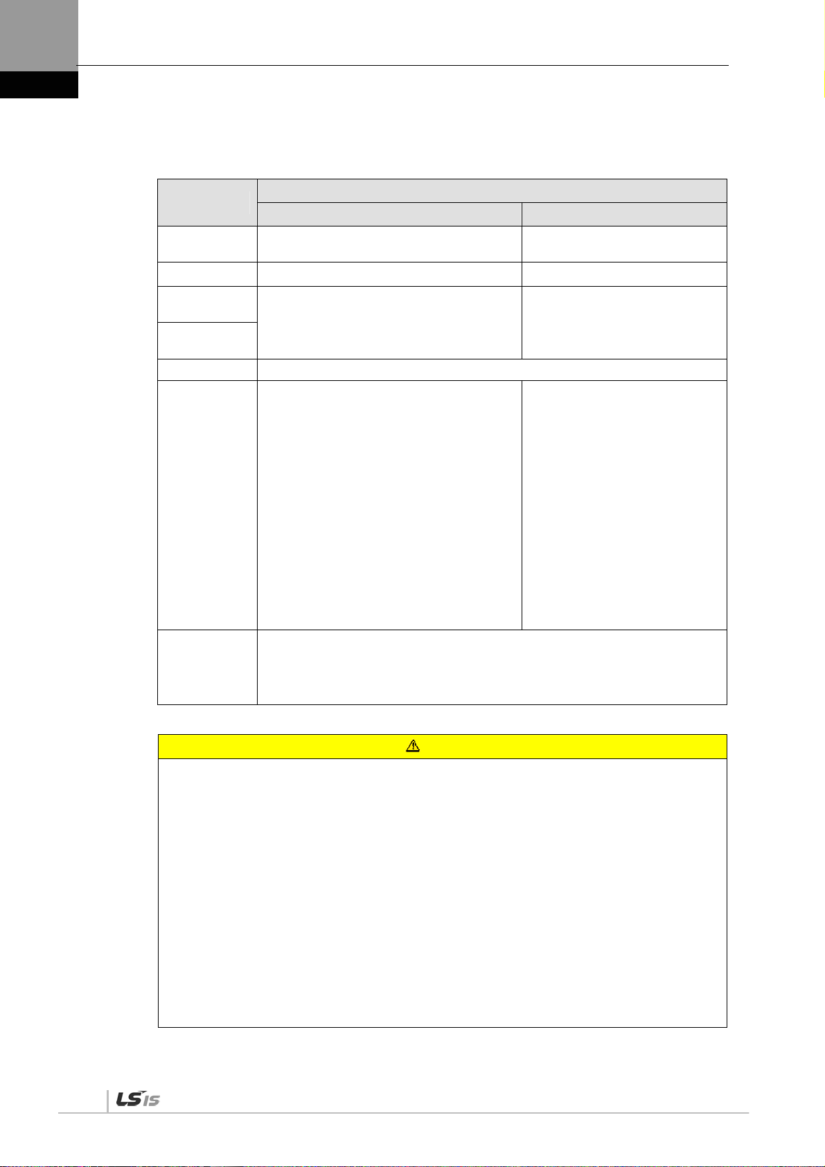
Store and operate this product under the following environmental conditions.
Environment
Conditions
Servo drive Servo motor
Operating
temp.
Storage temp. -20 ~ 65 ℃ -10 ~ 60 ℃
Operating
humidity
Storage
humidity
Altitude 1000 m or lower
0 ~ 50 ℃ 0 ~ 40 ℃
Below 90% RH (no condensation) 20~80% RH(no condensation)
When installing 1 unit:
More than 40 mm at the top and
bottom of the control panel
More than 10 mm on the left and right
sides of the control panel
When installing 2 or more units:
Spacing
More than 100 mm at the top of the
control panel
More than 40 mm at the bottom of the
control panel
More than 30 mm on the left and right
sides of the control panel
More than 2 mm between units
Refer to Section 2.2.1, "Wiring the
Control Panel."
Ensure the installation location is free from dust, iron, corrosive gas,
Other
and combustible gas.
Ensure the installation location is free from vibrations or the potential
for hard impacts.
Caution
Install the product with the correct orientation.
Do not drop the product or expose it to hard impact.
Install this product in a location that is free from water, corrosive gas, combustible
gas, or flammable materials.
Install this product in a location capable of supporting the weight of this product.
Do not stand on the product or place heavy objects on top of it.
Always maintain the specified spacing when installing the servo drive.
Ensure that there are no conductive or flammable debris inside the servo drive or the
servo motor.
Firmly attach the servo motor to the machine.
Install the servo motor with a correctly oriented decelerator.
Do not touch the rotating unit of the servo motor during operation.
Do not apply excessive force when connecting the couplings to the servo motor shaft.
Do not place loads on the servo motor shaft that exceed the specified amount.
iv

Introduction
Wiring Precautions
Caution
Always use an AC 380-480 V power input for the servo drive.
Always connect the servo drive to a ground terminal.
Do not connect commercial power directly to the servo motor.
Do not connect commercial power directly to the U, V, W output terminals of the servo
drive.
Connect the U, V, W output terminals of the servo drive directly to the U, V, W input
terminals of the servo motor, but do not install magnetic contactors between the wires.
Always use pressurized terminals with insulation tubes when connecting the servo
drive power terminal.
When wiring, be sure to separate the U, V, and W cables for the servo motor power
and encoder cable.
Always use the robot cable if the motor moves.
Before you perform power line wiring, turn off the input power of the servo drive, and
then wait until the charge lamp goes off completely.
Startup Precautions
Caution
Check the input voltage (AC 380-480 V) and power unit wiring before supplying power
to the device.
The servo must be in the OFF mode when you turn on the power.
Before you turn on the power, check the motor's ID and the encoder pulse for XDL-
L7NHB .
Set the motor ID[0x2000], encoder type[0x2001] and the encoder pulse [0x2002] for
XDL-L7NHB first after you turn on the power.
After you complete the above settings, set the drive mode for the servo drive that is
connected to the upper level controller in [0x6060].
Refer to Chapter 1.4 "System Configuration" to perform I/O wiring for the servo drive
according to each drive mode.
You can check the ON/OFF state for each input terminal of I/O at [0x60FD].
Handling and Operating Precautions
Caution
Check and adjust each parameter before operation.
Do not touch the rotating unit of the motor during operation.
Do not touch the heat sink during operation.
Be sure to attach or remove the I/O and ENCODER connectors when the power is off.
Extreme change of parameters may cause system instability.
v

Introduction
Usage Precautions
Caution
Install an emergency cut-off switch which immediately stops operation in an
emergency.
Reset the alarm when the servo is off. Be warned that the system restarts
immediately if the alarm is reset while the servo is on.
Use a noise filter or DC reactor to minimize electromagnetic interference. This
prevents nearby electrical devices from malfunctioning due to interference.
Only use approved servo drive and servo motor combinations.
The electric brake on the servo motor stops operation. Do not use it for ordinary
braking.
The electric brake may malfunction if the brake degrades or if the mechanical
structure is improper (for example, if the ball screw and servo motor are combined via
the timing belt). Install an emergency stop device to ensure mechanical safety.
Malfunction Precautions
Caution
Install a servo motor with an electric brake or separate the brake system for use
during emergencies or device malfunctions.
If an alarm occurs, solve the underlying cause of the problem. After solving the
problem and ensuring safe operation, deactivate the alarm and resume operation.
Do not approach the machine until the problem is solved.
Repair/Inspection Precautions
Caution
Before performing servicing tasks, turn off the power. Wait 15 minutes until the charge
lamp goes off, and then check the voltage. Enough voltage may remain in the
condenser after the power is off to cause an electric shock.
Only authorized personnel may repair and inspect the device or replace its parts.
Do not modify this device in any way.
General Precautions
Caution
This user manual is subject to change due to product modification or changes in
standards. If such changes occur, we issue a new user manual with a new product
number.
Product Application
Caution
This product is not designed or manufactured for machines or systems intended to
sustain human life.
This product is manufactured under strict quality control conditions. Nevertheless,
install safety devices if installing the device in a facility where product malfunctions
may result in a major accident or a significant loss.
vi

Introduction
EEPROM Lifespan
Caution
The EEPROM is rewritable up to 4 million times for the purpose of recording
parameter settings and other information. The servo drive may malfunction if the total
number of the following tasks exceeds 4 million, depending on the lifespan of the
EEPROM.
EEPROM recording as a result of parameter changes
EEPROM recording as a result of an alarm
vii

Table of Contents
Table of Contents
1. Product Configuration ....................................................................................... 1-1
1.1 Product Verification .......................................................................................................... 1-1
1.2 Product Specifications ..................................................................................................... 1-2
1.3 Part Names ...................................................................................................................... 1-4
1.3.1 Servo Drive Parts ............................................................................................. 1-4
1.3.2 Servo Motor Parts ............................................................................................. 1-9
1.4 System Configuration Example ..................................................................................... 1-10
2. Wiring and Connection ...................................................................................... 2-1
2.1 Installation of Servo Motor ............................................................................................... 2-1
2.1.1 Operating Environment .................................................................................... 2-1
2.1.2 Preventing Impact............................................................................................. 2-1
2.1.3 Motor Connection ............................................................................................. 2-1
2.1.4 The Load Device Connection ........................................................................... 2-2
2.1.5 Cable Installation .............................................................................................. 2-2
2.2 Installation of Servo Drive ................................................................................................ 2-3
2.2.1 Installation and Usage Environment ................................................................ 2-3
2.3 Internal Block Diagram of Drive ....................................................................................... 2-4
2.3.1 XDL-L7NH Drive Block Diagram (XDL-L7NHB010U~ XDL-L7NHB035U) ...... 2-4
2.3.2 XDL-L7NH Drive Block Diagram (XDL-L7NHB050U~ XDL-L7NHB075U) ...... 2-5
2.3.3 XDL-L7NH Drive Block Diagram (XDL-L7NHB150U) ...................................... 2-6
2.4 Power Supply Wiring ....................................................................................................... 2-7
2.4.1 Power Supply Wiring Diagram ......................................................................... 2-8
2.4.2 Power Circuit Electrical Components .............................................................. 2-11
2.4.3 Regenerative Resistor Options ...................................................................... 2-17
2.5 Wiring for Input/Output Signals ...................................................................................... 2-18
2.5.1 Names and Functions of Digital Input/Output Signals ................................... 2-18
2.5.2 Names and Functions of Analog Input/Output Signals .................................. 2-20
2.5.3 Examples of Connecting Input/Output Signals .............................................. 2-22
2.5.4 Examples of Connecting Input/Output Signals .............................................. 2-24
2.6 Wiring of Encoder Signal (ENCODER) .......................................................................... 2-25
2.6.1 Quadrature Encoder Signaling Unit Wiring .................................................... 2-25
2.6.2 Serial Encoder Signaling Unit Wiring ............................................................. 2-26
2.6.3 Multi-Turn Encoder Signaling Unit Wiring ...................................................... 2-28
2.6.4 Tamagawa Encoder Signaling Unit Wiring ..................................................... 2-29
2.6.5 EnDat 2.2 Encoder Signaling Unit Wiring ...................................................... 2-30
2.7 Wiring for Safety Function Signals (STO) ...................................................................... 2-31
2.7.1 Names and Functions of Safety Function Signals ......................................... 2-31
2.7.2 Example of Connecting Safety Function Signals ........................................... 2-32
2.7.3 Bypass Wiring of Safety Function Signal ....................................................... 2-33
2.8 Wiring for EtherCAT Communication Signals ................................................................ 2-34
2.8.1 Names and Functions of EtherCAT Communication Signals ......................... 2-34
2.8.2 Example of Drive Connection ......................................................................... 2-35
3. EtherCAT Communication ................................................................................. 3-1
3.1 Structure of CANopen over EtherCAT ............................................................................. 3-1
viii

Table of Contents
3.1.1 EtherCAT State Machine ................................................................................... 3-2
3.2 Status LED ........................................................................................................................ 3-3
3.3 Data Type .......................................................................................................................... 3-5
3.4 PDO assignment ............................................................................................................... 3-5
3.5 Synchronization Using the DC (Distributed Clock) ........................................................... 3-8
3.6 Emergency Messages ...................................................................................................... 3-9
4. CiA402 Drive Profile ........................................................................................... 4-1
4.1 State machine ................................................................................................................... 4-1
4.2 Operation Modes .............................................................................................................. 4-3
4.3 Position Control Modes ..................................................................................................... 4-5
4.3.1 Cyclic Synchronous Position Mode ................................................................... 4-5
4.3.2 Profile Position Mode ........................................................................................ 4-8
4.4 Velocity Control Mode .....................................................................................................4-13
4.4.1 Cyclic Synchronous Velocity Mode .................................................................4-13
4.4.2 Profile Velocity Mode .......................................................................................4-16
4.5 Torque Control Modes ....................................................................................................4-19
4.5.1 Cyclic Synchronous Torque Mode ...................................................................4-19
4.5.2 Profile Torque Mode ........................................................................................4-21
4.6 Homing ............................................................................................................................4-23
4.6.1 Homing Method ...............................................................................................4-24
4.7 Touch Probe Function ....................................................................................................... 4-2
5. Drive Application Functions.............................................................................. 5-1
5.1 Drive Front Panel .............................................................................................................. 5-1
5.1.1 7-Segment for indicating servo status ............................................................... 5-1
5.2 Input/Output Signals Setting ............................................................................................. 5-4
5.2.1 Assignment of Digital Input Signals ................................................................... 5-4
5.2.2 Assignment of Digital Output Signals ................................................................ 5-6
5.2.3 Use of User I/O .................................................................................................. 5-8
5.3 Electric Gear Setup .........................................................................................................5-15
5.3.1 Electric Gear ....................................................................................................5-15
5.3.2 Example of Electric Gear Setup ......................................................................5-16
5.4 Settings Related to Speed Control .................................................................................5-17
5.4.1 Smooth Acceleration and Deceleration ...........................................................5-17
5.4.2 Servo-lock Function .........................................................................................5-18
5.4.3 Signals Related to Speed Control ...................................................................5-18
5.5 Settings Related to Position Control ...............................................................................5-19
5.5.1 Position Command Filter .................................................................................5-19
5.5.2 Signals Related to Position Control .................................................................5-21
5.6 Settings Related to Torque Control .................................................................................5-22
5.6.1 Speed Limit Function .......................................................................................5-22
5.7 Positive/Negative Limit Settings .....................................................................................5-23
5.8 Setting the Brake Output Signal Function ......................................................................5-24
5.9 Torque Limit Function .....................................................................................................5-26
5.10 Gain switching function ...................................................................................................5-29
ix

Table of Contents
5.10.1 Gain group switching ...................................................................................... 5-29
5.10.2 P/PI Control Switching .................................................................................... 5-31
5.11 Dynamic brake ............................................................................................................... 5-33
5.12 Regenerative resistance setting .................................................................................... 5-34
5.12.1 Use of Internal Regenerative Resistor ........................................................... 5-35
5.12.2 Use of External Regenerative Resistor .......................................................... 5-37
5.12.3 Other Considerations ..................................................................................... 5-38
5.13 Configuration of Drive Node Address (ADDR) .............................................................. 5-39
6. Safety Functions ................................................................................................ 6-1
6.1 Safe Torque Off (STO) Function ...................................................................................... 6-1
6.2 External Device Monitor (EDM) ....................................................................................... 6-4
6.3 Example of Using Safety Function .................................................................................. 6-5
6.4 How to Verify Safety Function .......................................................................................... 6-5
6.5 Precautions for Using Safety Function ............................................................................ 6-6
7. Tuning .................................................................................................................. 7-1
7.1 Auto Gain Tuning ............................................................................................................. 7-1
7.2 Manual Gain Tuning ......................................................................................................... 7-2
7.2.1 Gain Tuning Sequence ..................................................................................... 7-3
7.3 Vibration Control .............................................................................................................. 7-5
7.3.1 Notch Filter ....................................................................................................... 7-5
7.3.2 Adaptive Filter ................................................................................................... 7-6
7.4 Analog Monitor ................................................................................................................. 7-7
8. Procedure Function ........................................................................................... 8-1
8.1 Manual JOG Operation .................................................................................................. 8-1
8.2 Programmed Jog Operation ............................................................................................ 8-2
8.3 Deleting Alarm History ..................................................................................................... 8-3
8.4 Auto Gain Tuning ............................................................................................................. 8-5
8.5 Index Pulse Search .......................................................................................................... 8-5
8.6 Absolute encoder reset .................................................................................................... 8-6
8.7 Instantaneous Maximum Torque Initialization .................................................................. 8-6
8.8 Phase current offset tuning .............................................................................................. 8-7
8.9 Software reset .................................................................................................................. 8-8
8.10 Commutation .................................................................................................................... 8-8
9. Object Dictionary ................................................................................................ 9-1
9.1 General Objects ............................................................................................................... 9-1
9.2 Manufacturer Specific Objects ....................................................................................... 9-17
9.3 CiA402 Objects .............................................................................................................. 9-68
10. Product Specifications .................................................................................... 10-1
10.1 Servo Motor ................................................................................................................... 10-1
10.1.1 Product Characteristcs ................................................................................... 10-1
10.1.2 Outline Diagram ........................................................................................... 10-19
x

Table of Contents
10.2 Servo Drive ...................................................................................................................10-29
10.2.1 Product Characteristics .................................................................................10-29
10.2.2 Outline Diagram ............................................................................................10-32
10.3 Options and Peripheral Devices ...................................................................................10-35
11. Maintenance and Inspection ......................................................................... 11-43
11. 1 Maintenance and Inspection ......................................................................................... 11-43
11.1.1 Precautions ................................................................................................... 11-43
11.1.2 What to Inspect ............................................................................................. 11-43
11.1.3 Replacing Parts ............................................................................................. 11-44
11. 2 Diagnosing and Troubleshooting Abnormalities ........................................................... 11-45
11.2.1 Servo Motor ................................................................................................... 11-45
11.2.2 Servo Drive .................................................................................................... 11-46
12. Test Drive ........................................................................................................ 11-54
12.1 Preparation for Operation ...............................................................................................12-3
12.2 Test Drive Using TwinCAT System Manager ..................................................................12-4
12.3 Test Drive Using LSIS PLC (XGT + PN8B) ..................................................................12-12
13. Appendix ......................................................................................................... 13-19
13.1 Firmware Update ..........................................................................................................13-19
13.1.1 Use of USB OTG ...........................................................................................13-19
13.1.2 Use of FoE (File access over EtherCAT) ......................................................13-21
13.1.3 Use of Drive CM ............................................................................................13-25
xi


1. Product Configuration
1. Product Configuration
1.1 Product Verification
1. Check the name tag to verify that the product received matches the model ordered
Does the servo drive's name plate match?
Does the servo motor's name plate match?
2. Check the product components and options.
Are the type and length of cables correct?
Does the regenerative resistor conform to the required standard?
Is the shape of the shaft correct?
Are there any abnormalities after mounting the oil seal or brake?
Are the gearbox and the gear ratios correct?
Is the encoder format correct?
3. Check the exterior of the device.
Are there any foreign substances or humidity in the device?
Is there any discoloration, contaminant, damage or disconnected wire?
Are the bolts tightly fastened to the joints?
Is there any abnormal sound or excessive friction during operation?
1-1

1. Product Configuration
1.2 Product Specifications
XDL-L7NH Series Product Type
XDL-L7 NH B 010 U AA
Series Name
L7 Series
L7 Series
Communication
/Drive Type
NH : Network type
All-in-One Type
Input voltage
A: 200Vac
B: 400Vac
Capacity
001 : 100W
002 : 200W
004 : 400W
008 : 750W
010 : 1kW
020 : 2kW
035 : 3.5kW
050 : 5.0kW
075 : 7.5kW
110 : 11.0k W
150 : 15kW
Encoder
U: Universal
Option
Black:
Standard
Marked:
Dedicated use
1-2

1. Product Configuration
S
e
Servo Motor Product Format
APM – S E P 10 D E K 1 G1 03
ervo Motor
Servo Motor
Motor Shape
Motor Shape
S: 실축형
S: Real Axis
H: Hollow Shaft
H: 중공축형
B: Assembly
B: 조립형
Flange Size
A: 40 Flange
B: 60 Flange
C: 80 Flange
D: 100 Flange
E: 130 Flange
F: 180 Flange
G: 220 Flange
Input
Input
Blank: 200[Vac]
P: 400[Vac
Motor
Motor
R3: 30[W]
R5: 50[W]
01: 100[W]
02: 200[W]
03: 300[W]
04: 400[W]
06: 550/600[W]
07: 650[W]
08: 750/800[W]
10: 1[kW]
15: 1.5[kW]
20: 2[kW]
35: 3.5[kW]
50: 5[kW]
75: 7.5[kW]
150: 15[kW]
220: 22[kW]
300: 30[kW]
370: 37[kW]
Encoder Type
Encoder Type
Quadrature(Pulse type)
A: Inc. 1024[ppr]
B: Inc. 2000[ppr]
C: Inc. 2048[ppr]
D: Inc. 2500[ppr]
E: Inc. 3000[ppr]
F: Inc. 5000[ppr]
G: Inc. 6000[ppr]
Serial
Com mu nication t ype
BiSS(
N : 19bit SingleTurn
M : 19bit MultiTurn
Rated RPM
A: 3000[rpm]
D: 2000[rpm]
G: 1500[rpm]
M: 1000[rpm]
Shaft Shape
N: Straight
One-sided round key
K: 한쪽 둥근키(표준)
(standard)
C: C Cut
D: D Cut
T: Taper 형상
Tape r sh ap e
R: 양쪽 둥근키
Double-sided
H: Hollow Shaft
Oil Seal, Brake Existence
Non-existen t: None included
Non-existent: None included
1: Oil Seal attached
1: Oil Seal attached
)
2: Brake attached
2: Brake attached
3: Oil Seal and Brak
3: Oil Sea l and B rake
Gearbox
Classification
03: 1/3
10: 1/10
Gearbox Sp ec.
Non-existent: No
gearbox
G1: For general
industrial purposes
G2: For general
industrial purposes
G3: Precise
Gearbox
1-3

1. Product Configuration
1.3 Part Names
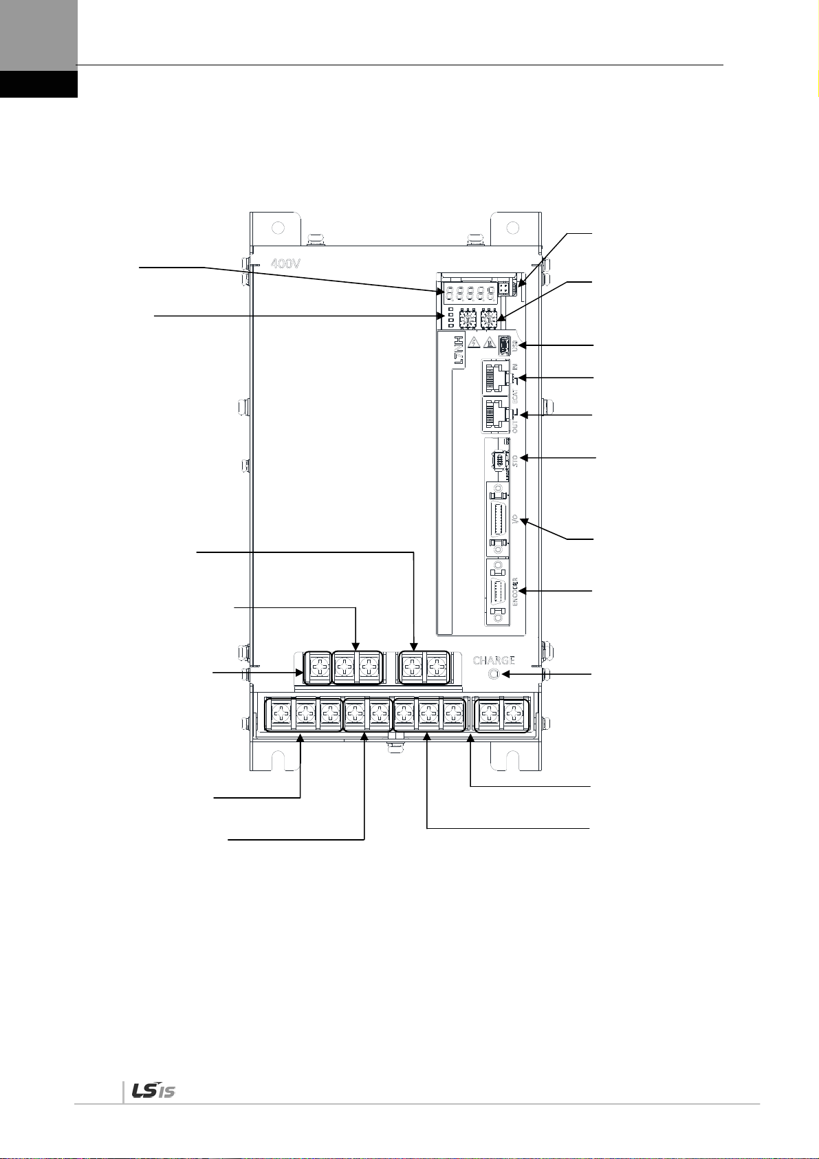
1.3.1 Servo Drive Parts
XDL-L7NH Drive (1KW)
Display
It shows drive status, alarms, etc.
CHARGE lamp
This turns on when the main circuit power is on.
Status LED
It indicates the current state of EtherCAT
communication.
Main power connectors (L1, L2, and L3)
These terminals connect to the main circuit power
input.
DC reactor connector (PO, PI)
These terminals connect to the DC reactor to
suppress high-frequency power.
-If the DC reactor is not used, be sure to shortcircuit this connector.
Regenerative resistance connector (B+, B, BI)
These terminals connect to the external regenerative resistor.
-For basic installations : Short-circuit B and BI terminals.
-For external resistor installations : Install to B+ and B terminals.
Control power terminals (C1 and C2)
These terminals connect to the control power input.
Connector for analog monitors
It is a connector for checking the analog output
signal.
Node address setting switch
This switch is to set the node address of the drive.
You can set the node addresses from 0 to 99.
USB connector (USB)
This connector is to communicate with a PC.
EtherCAT communication input port (ECAT IN)
EtherCAT communication output port (ECAT
OUT)
Safety connector (STO)
This connector connects safety devices.
-If a safety device is not used, be sure to install the
safety jump connector before use.
Input/output signal connector (I/O)
This connector is for sequence input/output signals.
Servo motor connection terminals (U,V,W)
These terminals connect to the main circuit cable
(power cable) of the servo motor.
Ground terminal
It is a ground terminal to prevent electric shock.
1-4
Encoder connector (ENCODER)
This connector connects to the encoder
installed in the servo motor.

1. Product Configuration
XDL-L7NH Drive (2KW, 3.5KW)
Display
It shows drive status, alarms, etc.
CHARGE lamp
This turns on when the main circuit
power is on.
Status LED
It indicates the current state of
EtherCAT communication.
Main power connectors
(L1, L2, and L3)
These terminals connect to the main
circuit power input.
DC reactor connector (PO, PI)
These terminals connect to the DC
reactor to suppress high-frequency
power.
-If the DC reactor is not used, be sure to
short-circuit this connector.
Regenerative resistance connector
(B+, B, BI)
These terminals connect to the external
regenerative resistor.
-For basic installations : Short-circuit B
and BI terminals.
-For external resistor installations:
Install to B+ and B terminals.
Control power terminals (C1 and C2)
These terminals connect to the control power
input.
Servo motor connection terminals (U,V,W)
These terminals connect to the main circuit cable
(power cable) of the servo motor.
Connector for analog monitors
It is a connector for checking the analog output
signal.
Node address setting switch
This switch is to set the node address of the
drive.
USB connector (USB)
This connector is to communicate with a PC.
EtherCAT communication input port (ECAT IN)
EtherCAT communication output port
(ECAT OUT)
Safety connector (STO)
This connector connects safety devices.
-If a safety device is not used, be sure to install
the safety jump connector before use.
Input/output signal connector (I/O)
This connector is for sequence input/output
signals.
Encoder connector (ENCODER)
This connector connects to the encoder
installed in the servo motor.
Ground terminal
It is a ground terminal to prevent electric
shock.
1-5
1. Product Configuration
*
XDL-L7NH Drive (5KW)
Connector for analog monitors
It is a connector for checking the analog
Display
It shows drive status, alarms,
etc.
Status LED
It indicates the current state of
EtherCAT communication.
output signal.
Node address setting switch
This switch is to set the node address of the
drive. You can set the node addresses from 0
to 99.
USB connector (USB)
This connector is to communicate with a PC.
EtherCAT communication input port
(ECAT IN)
EtherCAT communication output port
(ECAT OUT)
Safety connector (STO)
This connector connects safety devices.
-If a safety device is not used, be sure to
install the safety jump connector before use.
Control power terminals (C1 and C2)
These terminals connect to the control
power input.
DC reactor connector (PO, PI)
These terminals connect to the DC reactor
to suppress high-frequency power.
-If the DC reactor is not used, be sure to
short-circuit this connector.
It is not a connector for
connection (N)
Main power connectors (L1, L2, and L3)
These terminals connect to the main circuit
power input.
Regenerative resistance connector (B+, B)
These terminals connect to the external
regenerative resistor.
-For basic installations : Short-circuit B+ and B
terminals.
-For external resistor installations : After
attaching internal resistor wiring to the internal
resistor fixing hole “NC” of the case, connect
the external resistor to B+ and B terminals.
Input/output signal connector (I/O)
This connector is for sequence
input/output signals.
Encoder connector (ENCODER)
This connector connects to the encoder
installed in the servo motor.
CHARGE lamp
This turns on when the main circuit power
is on.
Ground terminal
It is a ground terminal to prevent electric
shock.
Servo motor connection terminals (U,V,W)
These terminals connect to the main circuit
cable (power cable) of the servo motor.
1-6

1. Product Configuration
*
XDL-L7NH Drive (7.5KW)
Connector for analog monitors
It is a connector for checking the analog
output signal.
Display
It shows drive status,
alarms, etc.
Status LED
It indicates the current state of
EtherCAT communication.
Node address setting switch
This switch is to set the node address of
the drive. You can set the node addresses
from 0 to 99.
USB connector (USB)
This connector is to communicate with a
PC.
EtherCAT communication input port
(ECAT IN)
EtherCAT communication output port
(ECAT OUT)
Safety connector (STO)
This connector connects safety
devices.
-If a safety device is not used, be sure
to install the safety jump connector
before use.
CHARGE lamp
This turns on when the main
circuit power is on.
It is not a connector
for connection (N)
DC reactor connector (PO, PI)
These terminals connect to the DC reactor to
suppress high-frequency power.
-If the DC reactor is not used, be sure to short-circuit
this connector.
Main power connectors (L1, L2,
and L3)
These terminals connect to the
main circuit power input.
* NC
Input/output signal connector (I/O)
This connector is for sequence
input/output signals.
Encoder connector
(ENCODER)
This connector connects to the
encoder installed in the servo
Control power terminals (C1 and C2)
These terminals connect to the control
power input.
Servo motor connection terminals
(U,V,W)
These terminals connect to the main
circuit cable (power cable) of the servo
motor.
Ground terminal
It is a ground terminal to prevent electric shock.
Regenerative resistance connector (B+, B)
These terminals connect to the external regenerative resistor.
-For basic installations : Short-circuit B+ and B terminals.
-For external resistor installations : After attaching internal resistor
wiring to the internal resistor fixing hole “NC” of the case, connect
the external resistor to B+ and B terminals.
1-7

1. Product Configuration
*
XDL-L7NH Drive (15KW)
Connector for analog monitors
Display
It shows drive status,
alarms, etc.
Status LED
It indicates the current state of
EtherCAT communication.
It is a connector for checking the analog
output signal.
Node address setting switch
This switch is to set the node address of the
drive. You can set the node addresses from 0
to 99.
USB connector (USB)
This connector is to communicate with a PC.
EtherCAT communication input port
(ECAT IN)
Control power terminals
(C1 and C2)
These terminals connect to
the control power input.
CHARGE lamp
This turns on when the
main circuit power is on.
Main power connectors (L1,
L2, and L3)
These terminals connect to the
main circuit power input.
It is not a connector for
connection (N)
DC reactor connector (PO, PI)
These terminals connect to the DC reactor to
suppress high-frequency power.
-If the DC reactor is not used, be sure to shortcircuit this connector.
Z
EtherCAT communication output port
(ECAT OUT)
Safety connector (STO)
This connector connects safety devices.
-If a safety device is not used, be sure to
install the safety jump connector before use.
Input/output signal connector (I/O)
This connector is for sequence
input/output signals.
Encoder connector (ENCODER)
This connector connects to the encoder
installed in the servo motor.
Servo motor connection terminals
(U,V,W)
These terminals connect to the main circuit
cable (power cable) of the servo motor.
Ground terminal
It is a ground terminal to prevent electric shock.
Regenerative resistance connector (B+, B)
These terminals connect to the external
regenerative resistor.
-Install external regenerative resistance
1-8

1. Product Configuration
1.3.2 Servo Motor Parts
80 Flange or below
130 Flange or higher
1-9

1. Product Configuration
1.4 System Configuration Example
The figure below shows an example of system configuration using this drive.
Power
전원
Three-phase AC380V
Molded case circuit
breaker
It is used to protect
배선용 차단 기
power line.
It turns the circuit OFF
전원라인을 보호하기
if overcurrent flows.
위하여 사용합니다.
과전류가 흐르면
회로를 OFF합니다.
Noise filter
노이즈 필터
It protects power line
전원라인으로부터의
from external noise.
외부 노이즈를
막습니다.
삼상 AC380V
R S T
Electromagnetic
전자 접촉 기
contactor
It turns servo
서보전원을 ON /
power ON / OFF.
OFF로 합니다.
Oscilloscope
오실로스코프
Analog monitor cable
아날로그 모니터 케이블
Servo Drive
서보 드라이브
DAQ
Upper device
상위 장치
XGT
EtherCAT 통신케이블
EtherCAT communication cable
Node address setting switch
Node 주소 설정 스위치
0
0
5
5
ADDR
Connect a
회생 저항 연결
regenerative resistor.
1.기본 장착 사용 시
1.When using basic
- 단락(B, B I)
installations
2.외부 저항 장착 시
-Short-circuit (B, BI)
- 장착(B, B +)
2.When installing
external resistance
-Install it (B, B+)
DC reactor connection
DC 리액터 연결
-미사용 시 단락(PO, PI)
-Short-circuit if not used
(PO, PI)
모터 케이 블
Motor cable
Servo Motor
서보모터
I/O Cable
3M
10314
Encoder cable
엔코더 케이 블
3M
10314
Safety cable
안전 케이 블
1.If the safety function
is not used : Install the
1. 안전기능 을
safety jump connector.
사용하지 않을 경우 :
안전점프 커넥터 설치
2.If the safety
2. 안전기능을 사용
function is used
할 경우 :
안전 기기
Safety device
Mini USB
미니 USB
케이블
cable
U
S
B
Mini USB
cable
미니 USB
케이블
Mini USB
미니 USB
adaptor
젠더
POTNOT HOME
1-10

2. Wiring and Connection
2. Wiring and Connection
2.1 Installation of Servo Motor
2.1.1 Operating Environment
Item Requirements Notes
Ambient
temperature
Ambient
humidity
External
vibration
0 ∼ 40[℃]
80% RH or lower Do not operate this device in an environment with steam.
Vibration acceleration
19.6 ㎨ or below on both
the X and Y axis.
Consult with our technical support team to customize the product if
temperatures in the installation environment are outside this range.
Excessive vibrations reduce the lifespan of the bearings.
2.1.2 Preventing Impact
Impact to the motor during installation or handling may damage the encoder.
Caution
2.1.3 Motor Connection
If the motor is directly connected to commercial power, it may be burned. Be sure to connect with
the specified drive before using it.
Connect the ground terminals of the motor to either of the two ground terminals inside the drive,
and attach the remaining terminal to the type-3 ground.
U – U
V - V
W – W
- F.G
Connect the U, V, and W terminals of the motor in the same way as the U, V, and W terminals of
the drive.
Ensure that the pins on the motor connector are securely attached.
In order to protect against moisture or condensation in the motor, make sure that insulation
resistance is 10 ㏁ (500 V) or higher before installation.
2-1

2. Wiring and Connection
2.1.4 The Load Device Connection
For coupling connections: Ensure that the motor shaft and load shaft are aligned within the tolerance
range.
Load
shaft
0.03 ㎜ or below (peak to peak)
0.03 ㎜ or below (peak to peak)
Motor
shaft
For pulley connections:
Flange
40 148 15 39 4
60 206 21 69 7
80 255 26 98 10
130 725 74 362 37
180 1548 158 519 53
220 1850 189 781 90
Lateral Load Axial Load
N kgf N kgf
Notes
Nr: 30 ㎜ or below
Lateral load
Axial load
2.1.5 Cable Installation
For vertical installations, make sure that no oil or water flows into the connecting parts.
Do not apply pressure to or damage the cables. Use robot cables to prevent swaying when the
motor moves.
2-2

2. Wiring and Connection
2.2 Installation of Servo Drive
2.2.1 Installation and Usage Environment
Item
Ambient
temperature
Ambient
humidity
External
vibration
Ambient
conditions
Environmental
conditions
0∼50[℃]
90% RH or lower
Vibration
acceleration 4.9
㎨ or lower
Caution
Install a cooling fan on the control panel to maintain an
appropriate temperature.
Caution
Condensation or moisture may develop inside the drive during
prolonged periods of inactivity and damage it. Remove all
moisture before operating the drive after a prolonged period of
inactivity.
Excessive vibration reduces the lifespan of the machine and
may cause malfunctions.
Notes
Do not expose the device to direct sunlight.
Do not expose the device to corrosive or combustible gases.
Do not expose the device to oil or dust.
Ensure that the device receives sufficient ventilation.
2-3

2. Wiring and Connection
035
r
t
t
t
p
p
2.3 Internal Block Diagram of Drive
2.3.1 XDL-L7NH Drive Block Diagram
(XDL-L7NHB010U~ XDL-L7NHB035U)
3-phase power
3상 전원
AC380~480V
Control Power Phase
Loss Detection Circuit
Single-phase power
단상 전원
AC380V~480V
입력
제어전원결상
검출회로
Input
입력
C1
C2
0
1
9
2
8
3
7
4
6
5
x10
Input
L1
L2
L3
ECAT IN/OUT
0
1
9
8
7
4
6
5
x1
S
M
P
S
2
3
Diode
Thermistor
써미스터
Main Power Phase
주전원결상
Loss Detection
Circuit
검출회로
USB
010 : Thermistor
EtherCAT
EtherCAT
Communication
통신
USB
USB
communication
통신
안전기능입력
Safety Function Inpu
(2점)
(2 Points)
Note 1)
주1) 주2)
써미스터
: Resistor
Chage
Lamp
B
B+
회생저항
Regenera tive
Resisto
Thermistor
써미스터
PI
PO
T1
Main 제어
DC전압
DC Voltage
Detection Circuit
검출회로
내부온도
Internal
Temperature
검출회로
Detection Ci rcuit
U,V Curren
U,V전류
DC Voltage
DC전압
Relay
driving circuit
구동회로
Main Control POWER circuit connection
A/D Conversion
A/D 변환
ESC
USB OTG FS
P/C 절연 I/F
P/C Insulation I/F
안전기능출력
Safety F unction Outpu
(1점)
(1 Point)
Digital input
디지털입력
(8점)
oints)
(8
Note 2)
BI
T2
회생제동
Regenera tive
Brake Drive
Circuit
구동회로
POWER 회로 접속
MCU / FPGA
IGBT온도
IGBT Temperature
검출회로
Detection Circuit
Digital Output
디지털출력
(4점)
(4
oints)
IGBT
Current sensor
전류 센서
PWM신호
PWM Signal SC
Detection Circuit
SC검출회로
아날로그 입력
Analog Input (1 Point)
(1점)
U,V전류
U and V Current
Detection Ci rcuit
검출회로
BiSS-C
Quadrature
TAMAGAWA
EnDat
Analog output
(2 points)
Note 3)
U
V
W
엔코더
Encoder Input
아날로그출력
(2점)
주3)
DB
DB Drive Circuit
구동회로
입력
M
E
ENCODER
2-4
Safety device c onnection (STO)
안전기기 연결(STO)
Input/output connection (I/O)
입/출력 연결(I/O)
Analog output connection
아날로그 출력 연결
Note 1) If using a DC reactor, connect the PO and PI pins.
Note 2) If using an external regenerative resistor, remove the B and BI short-circuit pins and
connect the B+ and B pins.
Note 3) XDL-L7NHB010U~ XDL-L7NHB035U Model is cooled by a DC 24 V cooling fan.

2. Wiring and Connection
t
(
t
(
)
p
(4 p
)
(2 p
g
r
2.3.2 XDL-L7NH Drive Block Diagram
(XDL-L7NHB050U~ XDL-L7NHB075U)
3-phase power
3상 전원
AC380~480V
제어전원결상
Control Power Phase
Loss Detection Circuit
Single-phase power
단상 전원
AC380V~480V
검출회로
Input
입력
C1
C2
0
9
8
7
6
5
x10
입력
1
2
3
4
Input
L1
L2
L3
ECAT IN/OUT
0
9
8
7
6
5
x1
1
2
3
4
Main Power Phase
주전원결상
Loss Detection
S
M
P
S
USB
Diode
Thermistor
써미스터
Circuit
검출회로
EtherCAT
Communication
USB
communication
EtherCAT
통신
USB
통신
Note 4)
주1) 주5)
써미스터
Resistor
Chage
Lamp
Internal
내부온도
Temperature
Detection Ci rcuit
검출회로
U,V전류
U,V Current DC
DC전압
Volt a
e
Relay
driving circuit
구동회로
Main 제어
Main Control
A/D Conversion
A/D 변환
DC전압
DC Voltage
Detection Circuit
검출회로
BB+
Regenera tive
PI
PO
ESC
USB OTG FS
P/C Insulation I/F
P/C 절연 I/F
Note 5)
회생저항
Resisto
Thermistor
써미스터
T1
T2
Regenera tive
회생제동
Brake Drive
Circuit
구동회로
POWER 회로 접속
POWER circuit connection
MCU / FPGA
IGBT
IGBT온도
IGBT Temperature
Detection Circuit
검출회로
전류 센서
PWM신호
PWM Signal SC
Detection Ci rcuit
SC검출회로
Current sensor
U and V Current
Detection Ci rcuit
BiSS-C
Quadrature
TAMAGAWA
EnDat
U,V전류
검출회로
Note 6)
주6)
U
V
W
DB Drive Circuit
입력
엔코더
Encoder Input
DB
구동회로
M
E
ENCODER
안전기능입력
Safety Function Inpu
(2점)
2 Points)
Safety device c onnection (STO)
안전기기 연결(STO)
안전기능출력
Safety Function Outpu
(1점)
1 Point
Digital input
디지털입력
(8점)
(8
oints)
Digital Output
디지털출력
(4점)
oints
입/출력 연결(I/O)
아날로그 입력
Analog Input (1 Point)
(1점)
Analog output
아날로그출력
(2점)
oints)
Analog output connection Input/output connection (I/O)
아날로그 출력 연결
Note 4) If using a DC reactor, connect the PO and PI pins.
Note 5) If the external regenerative resistor is used, after attaching internal resistor wiring to the
internal resistor fixing hole “NC” of the case, connect the external regenerative resistor to
B+ and B terminals.
Note 6) XDL-L7NHB050U ~ XDL-L7NHB075U models are cooled by a DC 24 V cooling fan.
2-5

2. Wiring and Connection
r
g
P/C I
I/F
p
p
p
p
p
2.3.3 XDL-L7NH Drive Block Diagram (XDL-L7NHB150U)
External
regenerative
resistor
Note 7)
Resistor
Note 8)
Note 9)
Control Power Phase
Loss Detection Circuit
Single-phase
Input
9
8
7
DC Voltage
nsulation
Digital input
(8
Regenera tive
Resisto
Thermistor
Regenera tive
oints)
Brake Drive
IGBT Temperature
Circuit
Detection Circuit
POWER circuit connection
Digital Output
(4
oints)
Input/output connection (I/O)
PWM Signal SC
Detection Circuit
Analog Input
(1 Point)
Current sensor
U and V Current
Detection Ci rcuit
Analog output connection
Encoder Input
Analog output
(2
oints)
DB Drive Circuit
Input 3-phase power
Thermistor
Main Power Phase
Loss Detection
Circuit
EtherCAT
Communication
USB
1
1
9
2
2
8
3
3
7
4
4
6
6
communication
Internal
Temperature
Detection Ci rcuit
U,V Current DC
e
Volt a
Safety Function
In
ut (2 Points)
Safety device c onnection (STO)
driving circuit
A/D Conversion
Safety Function
Out
ut (1 Point)
Detection Circuit
2-6
Note 7) If using a DC reactor, connect the PO and PI pins.
Note 8) XDL-L7NHB150U model has no internal regenerative resistance. The external regenerative
resistance is used. When attaching the resistance, connect it to B+ and B terminals.
Note 9) XDL-L7NHB150U Model is cooled by a DC 24 V cooling fan.

2. Wiring and Connection
2.4 Power Supply Wiring
Ensure that the input power voltage is within the acceptable range.
Caution
Overvoltages can damage the drive.
If commercial power is connected to U, V, W terminals of Drive, they may be damaged. Be sure to
connect power to L1, L2, L3 terminals.
Connect short-circuit pins to the B and BI terminals. For external regenerative resistors, remove the
short-circuit pins and use standard resistors for the B+ and B terminals.
Model Resistance
XDL-L7NHB010U
XDL-L7NHB020U
XDL-L7NHB035U
XDL-L7NHB050U
XDL-L7NHB075U
XDL-L7NHB150U
100[]
40[]
27[]
27[]
13.4[]
Standard
Capacity
Built-in 100 W
Built-in 150 W
Built-in 120 W
Built-in 240 W
External 2000 W
* Notes
Caution
For information about resistance during
regenerative capacity expansion, refer to
Section 2.4.3, "Regenerative Resistor
Options.”
Configure the system so that the main power (L1, L2, L3) is supplied after the control power (C1,
C2). (Refer to section 2.4.1, “Power Supply Wiring Diagram.”)
High voltages may remain in the device for sometime even after the main power is disconnected.
Please be careful.
Warnings
After disconnecting the main power, ensure that the charge lamp is off before you start wiring.
Failure to do so may result in electric shock.
Always ground the device over the shortest possible distance. Long ground wires are susceptible to
noise which may cause the device to malfunction.
2-7

2. Wiring and Connection
2.4.1 Power Supply Wiring Diagram
Power Supply Wiring Diagram(XDL-L7NHB010U~ XDL-L7NHB035U)
AC 380~480[V]
RST
Main
OFF
NF
Note 1)
주1)
Main
ON
RA
1Ry1MC
1SK
1MC
Servo Drive
서보드라이브
DC 리액터
DC reactor
PI
P
O
L1
L2
U
V
W
L3
C1
C2
1Ry
+2
4V
RA
Alarm+
Alarm-
17
18
B+
B
BI
Note 2)
I/O
Note 1) It takes approximately one to two seconds until alarm signal is output after you turn on the
E
엔코더
Encoder
외부
External
주2)
회생저항
regenerative
resistor
main power. Accordingly, push and hold the main power ON switch for at least two seconds.
Note 2) Short-circuit B and BI terminals before use, because XDL-L7NHB010U(100[W], 100[]) and
XDL-L7NHB020U~ XDL-L7NHB035U(150[W], 40[]) have internal regenerative resistance. If the
regenerative capacity is high because of frequent acceleration and deceleration, open the
short-circuit pins (B , BI) and connect an external regenerative resistor to B and B+.
Note 3) Remove approximately 7-10 ㎜ of the sheathing from the cables for the main circuit
power and attach crimp terminals. (Refer to Section 2.4.2, "Power Circuit Electrical
Components.”)
Note 4) Use a (-) flathead screwdriver to connect or remove the main circuit power unit wiring.
2-8

2. Wiring and Connection
Power Supply Wiring Diagram(XDL-L7NHB050U~ XDL-L7NHB075U)
Note 1)
Servo Drive
DC reactor
Power Supply Wiring Diagram(XDL-L7NHB150U)
Note 6)
Encoder
External
regenerative
resistor
Note 1)
Servo Drive
DC reactor
Note 7) External
Encoder
regenerative
resistor
2-9

2. Wiring and Connection
Note 5) It takes approximately one to two seconds until alarm signal is output after you turn on the
main power. Accordingly, push and hold the main power ON switch for at least two seconds.
Note 6) Short-circuit B and BI terminals before use, because XDL-L7NHB050U(120[W], 27[]),
XDL-L7NHB075U(240[W], 27[]) have internal regenerative resistance. If the regenerative
capacity is high because of frequent acceleration and deceleration, attach the short-circuit
pins (B+, B) to NC terminal and connect an external regenerative resistor to B+ and B
before use.
Note 7) By default, use external regenerative resistance for XDL-L7NHB150U(2000[W], 13.4[]), and
connect the resistance to B+ and B terminals before use.
Note 8) For the cables for the main circuit and control power unit, you must use crimp terminals
(XDL-L7NHB050U, XDL-L7NHB075U : GP110028_KET, XDL-L7NHB150U : GP110732_KET)
compliant with electrical components.
(Refer to Section 2.4.2, "Power Circuit Electrical Components.”)
XDL-L7NHB050U, XDL-L7NHB075U and XDL-L7NHB150U use terminal block, so use (+) and (-)
screwdrivers to connect or remove the terminals.
2-10

2. Wiring and Connection
2.4.2 Power Circuit Electrical Components
Name
MCCB
Noise Filter (NF)
XDL-
L7NHB010U
30A Frame
10A
(ABE33b/10)
TB6-
B010LBEI
(10A)
XDL-
L7NHB020U
XDL-
L7NHB035U
30A Frame
20A
(ABE33b/20)
TB6-
B020NBDC
(20A)
XDL-
L7NHB050U
30A Frame
30A
(ABE33b/30)
TB6-
B030NBDC
(30A)
XDL-
L7NHB075U
30A Frame
30A
(ABE33b/30)
TB6-
B040A
(40A)
XDL-
L7NHB150U
50A Frame
50A
(ABE53b/50)
TB6-
B060LA
(60A)
DC reactor 10[A] 20[A] 30[A] 30[A] 50[A]
MC
9A / 550V
(GM-12)
18A / 550V
(GM-22)
26A / 550V
(GM-40)
26A / 550V
(GM-40)
38A / 550V
(GM-50)
L1, L2 ,L3,
1)
PO, PI, N
B+, B,
U, V, W
Wire
Note
C1, C2
Crimp terminal
Regenerative
Resistor
(Default)
100[W]
100
AWG14 (2.08 ㎟)
AWG14 (2.08 ㎟)
UA-F4010, SEOIL
(10mm Strip & Twist)
150[W] 40 120[W] 27 240[W] 27
AWG10
(5.5 ㎟)
GP110028
KET
AWG10
(5.5 ㎟)
GP110028
KET
AWG8
(8.0 ㎟)
GP110732
KET
Connector
(Default)
Note 1) When you select a wire, please use 600V, PVC-insulated wire.
BLZ 7.62HP/3/180LR SN OR BX SO
BLZ 7.62HP/11/180LR SN OR BX SO
To comply with UL(CSA) standards, use UL-certified wire (heat resistant temperature 75℃ or
above).
To comply with other standards, use proper wires that meet applicable standards.
For other special specifications, use wires equivalent or superior to those in this section.
2-11

2. Wiring and Connection
XDL-L7NHB010U
Wire strip
~
Weidmuller
SD 0.6x3.5x100
XDL-L7NHB020U / XDL-L7NHB035U
Wire strip
~
M4 : 1.2[N*m]
2-12
Weldmuller
M4 : 1.2[N*m]
SD 0.6x3.5x100

2. Wiring and Connection
For information on wiring to BLZ 7.62HP Series connector, refer to the above procedures.
1) Insert electric wire into insert hole with upper locking screw loosened, and use applicable flathead (-) driver
for each model to fully tighten screw to 0.4-0.5 N·m.
2) Otherwise, insufficient torque of locking screw may cause vibration-induced disconnection, system
malfunction and contact-induced fire accident.
3) After you connect a wire to connector, place the connector as closely to servo drive as possible and use
both locking hooks to fully lock it.
4) Use FG locking screw of M4 size (shown in bottom of product) to tighten it to 1.2 N·m.
5) Insufficient torque of locking screw may cause FG contact failure and even malfunctioning drive.
6) Recommended (-) driver: Use Weidmuller flathead driver (SD 0.6×3.5×100).
2-13

2. Wiring and Connection
XDL-L7NHB050U
TB3
TB2
TB1
NC : Internal Regenerative Resistor
Screw for Fixing Lead Terminal
Terminal signal
TB1
L1 L2 L3 B+ B U V W FG FG
TB2
N PO P1
TB3
C1 C2
Terminal screw: M4
Tightening torque: 1.2 N·m
Terminal screw: M4
Tightening torque: 1.2 N·m
Terminal screw: M4
Tightening torque: 1.2 N·m
1) Otherwise, insufficient torque of locking screw may cause vibration-induced disconnection, system malfunction
and contact-induced fire accident.
2) Use FG locking screw of M4 size (shown in bottom of product) to tighten it to 1.2 N·m.
2-14

2. Wiring and Connection
XDL-L7NHB075U
TB3
TB2
TB1
NC : Internal Regenerative Resistor
Screw for Fixing Lead Terminal
Terminal signal
Terminal screw
Tightening torque
Terminal screw
Tightening torque
Terminal screw
Tightening torque
1) Otherwise, insufficient torque of locking screw may cause vibration-induced disconnection, system malfunction
and contact-induced fire accident.
2) Use FG locking screw of M4 size (shown in bottom of product) to tighten it to 1.2 N·m.
2-15

2. Wiring and Connection
XDL-L7NHB150U
TB2
TB1
Terminal signal
1) Otherwise, insufficient torque of locking screw may cause vibration-induced disconne ction, system malfunction
and contact-induced fire accident.
TB1
L1 L2 L3 N PO PI B+ B U V W
TB2
C1 C2
FG
Terminal screw: M5
Tightening torque: 3.24 N·m
Terminal screw: M4
Tightening torque: 1.2 N·m
Terminal screw: M5
Tightening torque: 3.24 N·m
2) Use FG locking screw of M4 size (shown in bottom of product) to tighten it to 1.2 N·m.
2-16

2. Wiring and Connection
2.4.3 Regenerative Resistor Options
Category
Resistance
Resistance
Product
Name
Braking
resistance
Braking
resistance
Name
IRV300-82
82[]
(300W)
IRV600-
140
70]
(600W *2P)
- Making
under review
Applicable
Drive
XDL-
L7NHB010U
XDL-
L7NHB020U
/ XDL-
L7NHB035U
(2P)
Specifications
Resistance
Resistance
Braking
resistance
Braking
resistance
IRV600-75
25[]
(600W *3P)
IRM2000-
13.4
13.4[]
(2000W)
XDL-
L7NHB050U
/ XDL-
L7NHB075U
(3P)
XDL-
L7NHB150U
2-17

2. Wiring and Connection
2.5 Wiring for Input/Output Signals
I/O Connector Specification : 10120-3000PE (3M)
Analog Monitoring Connector Specification : DF-11-4DS-2C (HIROSE)
2.5.1 Names and Functions of Digital Input/Output
Signals
Names and Functions of Digital Input Signals (I/O Connector)
Pin
Number
6 +24V DC 24V
11 DI1 POT
name assignment Details Function
DC 24V
INPUT
Forward
(CCW)
prohibited
COMMON
The actuator stops the servo motor to
prevent it from moving beyond the
motion range in forward direction.
2-18
Reverse
12 DI2 NOT
7 DI3 HOME Origin sensor
8 DI4 STOP Servo stop
(CW)
prohibited
The actuator stops the servo motor to
prevent it from moving beyond the
motion range in reverse direction.
Connects the origin sensor to return to
the origin.
Stops the servo motor when the contact
is on.

2. Wiring and Connection
13 DI5 PCON
14 DI6 GAIN2
9 DI7 PCL
10 DI8 NCL
** PROBE1
** PROBE2
** EMG
** ARST Alarm reset Resets the servo alarm.
** LVSF1
** LVSF2
Suppression
Suppression
P control
action
Switch from
Gain 1 to 2
Forward
torque limit
Negative
torque limit
Touch
probe 1
Touch
probe 2
Emergency
stop
Vibration
Filter 1
Vibration
Filter 2
When the contact is on, it converts the
mode from PI control to P control.
When the contact is on, it switches the
speed control gain 1 the gain 2
When the contact is on, the forward
torque limit function is activated.
When the contact is on, the negative
torque limit function is activated.
The probe signal to rapidly store the
position value (1)
The probe signal to rapidly store the
position value (2)
Emergency stop when the contact is on.
Depending on the Vibration
Suppression Filter function
setting(0x2515), using filter 1 signal
Depending on the Vibration
Suppression Filter function
setting(0x2515), using filter 2 signal
** SVON Servo On Servo On
Note 1) **Signals not assigned by default as factory setting. The assignment may be changed by
parameter setting. For more information, refer to 「5.2 Input/Output Signals Setting.」
Note 2) Wiring can be also done by using COMMON (DC 24 V) of the input signal as the GND.
Names and Functions of Digital Output Signals
Pin
Number
1 DO1+ BRAKE+
2 DO1- BRAKE-
17 DO2+ ALARM+
18 DO2- ALARM-
3 DO3+ RDY+
4 DO3- RDY-
19 DO4+ ZSPD+
20 DO4- ZSPD-
Name assignment Details Function
Brake Outputs brake control signal.
Servo alarm Outputs signal when alarm occurs.
This signal is output when the main
Servo ready
Zero speed
reached
power is established and the
preparations for servo operation are
complete.
Outputs a signal when the current speed
drops below the zero speed.
** INPOS1
Position
reached 1
Outputs signal when having reached the
command position (1)
2-19

2. Wiring and Connection
** TLMT Torque Limit
** VLMT Speed limit
** INSPD
** WARN
** TGON
** INPOS2
** Unassigned signals. The assignment may be changed by parameter setting. For more
information, refer to 「5.2 Input/Output Signals Setting.」
Speed
reached
Servo
warning
Rotation
detection
Position
reached 2
Outputs signal when the torque is
limited.
Outputs signal when the speed is
limited.
Outputs signal upon reaching the
command speed.
Outputs signal when a warning occurs.
Outputs signal when the servo motor is
rotating above the set value.
Outputs signal when having reached the
command position (2)
2.5.2 Names and Functions of Analog Input/Output
Signals
Names and Functions of Analog Input Signals (I/O Connector)
Pin
Number
15 A-TLMT Analog torque limit
5 AGND AGND (0V) Analog ground
Name Details Function
It applies -10~+10V between A-TMLT(AI1) and
AGND to limit motor output torque. Relationship
between input voltage and limit torque depends on
the value of [0x221C].
Names and Functions of Analog Output Signals (Analog Monitoring
Connector)
Pin
Number
1 AMON1 Analog Monitor 1 Analog monitor output (-10V ~ +10)
2 AMON2 Analog Monitor 2
3 AGND AGND (0V) Analog ground
4 AGND AGND (0V) Analog ground
Note 1) You can change the output variables to be monitored with analog monitor output by parameter
setting.
Name Details Function
Analog monitor output (-10V ~ +10)
2-20
For more information, refer to 「5.2.3 Analog Monitor.」

2. Wiring and Connection
2-21

2. Wiring and Connection
2.5.3 Examples of Connecting Input/Output Signals
Examples of Connecting Digital Input Signals
Caution
1. The input contact can be set to the contact A or the contact B, based on the characteristics of
individual signal.
2. Each input contact can be assigned to 15 functions.
3. For more information on signal assignment and contact change of the input contact, refer to 5.2
Input/Output Signals Setting.
4. The rated voltage is DC 12 V to DC 24 V.
Servo Drive
Internal
Circuit
Internal
Circuit
R1 : 3.3K, R2 : 680
Example of Connecting Digital Output Signals
Caution
1. The output contact can be set to the contact A or the contact B, based on the characteristics of
individual signal.
2. Each output contact can be assigned to 11 output functions.
3. For more information on signal assignment and contact change of the output contact, refer to
5.2 Input/Output Signals Setting.
4. Overvoltages or overcurrents may damage the device because it uses an internal transistor
switch.
5. The rated voltage and current are DC 24 V ± 10% and 120 [㎃].
2-22

2. Wiring and Connection
Servo Drive
Internal
Circuit
Internal
Circuit
Note 1) For DO1~ DO4 output signals, the GND24 terminal is separated.
Example of Connecting Analog Output Signals
Caution
1. For more information on settings and scale adjustment of monitoring signals, refer to 5.2.3
Assignment of Analog output signals.
2. The range of analog output signals is -10V to 10V.
3. The resolution of analog output signal is 12 bits.
4. The maximum load current allowed is 2.5 [mA].
5. The stabilization time is 15 [us].
Servo Drive
2-23

2. Wiring and Connection
2.5.4 Examples of Connecting Input/Output Signals
Analog torque
limit
Digital Input
Analog Input
Digital Output
2-24
Safe function input
Safety function output
Analog Output
Note 1) The input signals DI1 - DI8 and output signals DO1 - DO4 are the factory default signals.

2. Wiring and Connection
2.6 Wiring of Encoder Signal (ENCODER)
ENCODER Connector Specification: 10114-3000VE (3M)
2.6.1 Quadrature Encoder Signaling Unit Wiring
APCS-EAS Cable
Servo Drive Servo Motor
Encoder
2-25

2. Wiring and Connection
APCS-EBS Cable
Servo Motor
Encoder
Servo Drive
2.6.2 Serial Encoder Signaling Unit Wiring
APCS-ECS Cable
Servo Motor
Encoder
Servo Drive
2-26

2. Wiring and Connection
APCS-EDS Cable
Servo Motor
Encoder
Servo Drive
APCS-EES Cable
Servo Motor
Encoder
Servo Drive
2-27

2. Wiring and Connection
2.6.3 Multi-Turn Encoder Signaling Unit Wiring
APCS-ECS1 Cable
Servo Motor
Encoder
Servo Drive
APCS-EDS1 Cable
Servo Motor
Encoder
Servo Drive
2-28

2. Wiring and Connection
APCS-EES1 Cable
Servo Motor
Encoder
Servo Drive
2.6.4 Tamagawa Encoder Signaling Unit Wiring
Servo Motor
Encoder
Servo Drive
2-29

2. Wiring and Connection
2.6.5 EnDat 2.2 Encoder Signaling Unit Wiring
Servo Motor
Encoder
Servo Drive
2-30

2. Wiring and Connection
2.7 Wiring for Safety Function Signals (STO)
2069577-1(Tyco Electronics)
2143658
7
2.7.1 Names and Functions of Safety Function Signals
Pin
Number
1 +12V
2 -12V
3 STO1- DC 24 V GND
4 STO1+ Blocks the current (torque) applied to the motor when the signal is off.
5 STO2- DC 24 V GND
6 STO2+ Blocks the current (torque) applied to the motor when the signal is off.
name Function
For bypass wiring
7 EDM+
8 EDM-
Monitor output signal for checking the status of safety function input
signal
2-31

2. Wiring and Connection
2.7.2 Example of Connecting Safety Function Signals
Caution
1. The rated voltage is DC 12 V to DC 24 V.
2. With the contacts of STO1 and STO2 off, the motor output current is blocked.
24 V power
Driving signal
Blocking
Blocking
Safety Module
2-32

2. Wiring and Connection
2.7.3 Bypass Wiring of Safety Function Signal
This drive provides the Mini I/O Bypass connector which has Bypass wiring to be used for the
convenience of the user when the STO function is not used. To use the Bypass function, connect the
Mini I/O Plug connector as follows.
If you connect +12V to STO2-, -12V to STO1+ and STO1- to STO2+ for wiring of the Mini I/O Plug
connector, you can bypass the safety function signal. Never use this power (+12V,-12V) except for this
purpose.
Mini I/O By-pass Connector
Mini I/O Plug Connector
1971153-1(Tyco Electronics)
2069577-1(Tyco Electronics)
2-33

2. Wiring and Connection
2.8 Wiring for EtherCAT Communication Signals
2.8.1 Names and Functions of EtherCAT
Communication Signals
EtherCAT IN and EtherCAT OUT Connector
Pin
Number
1 TX/RX0 +
2 TX/RX0 -
3 TX/RX1+
4 TX/RX2 -
5 TX/RX2 +
6 TX/RX1 -
7 TX/RX3 +
8 TX/RX3 -
Note 1) EtherCAT only uses signals from No. 1, 2, 3, and 6.
Signal Name Line color
White/Orange
Orange
White/Green
Blue
White/Blue
Green
White/Brown
Brown
Plate Shield
2-34

2. Wiring and Connection
2.8.2 Example of Drive Connection
The following figure shows the connection between a master and slave using EtherCAT communication.
This is an example of a connection by topology of basic line type.
For an environment with much noise, install ferrite core at both ends of the EtherCAT cable.
2-35

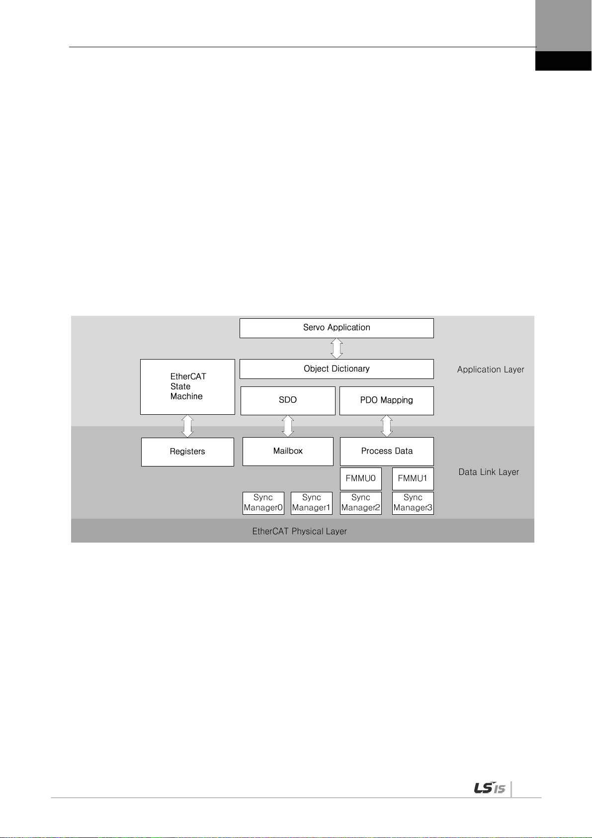
3. EtherCAT Communication
3. EtherCAT Communication
EtherCAT stands for Ethernet for Control Automation Technology. It is a communication method for
masters and slaves which uses Real-Time Ethernet, developed by the German company BECKHOff
and managed by the EtherCAT Technology Group (ETG).
The basic concept of the EtherCAT communication is that, when a DataFrame sent from a master
passes through a slave, the slave inputs the received data to the DataFrame as soon as it receives the
data.
EtherCAT uses a standard Ethernet frame compliant with IEEE802.3. Based on the Ethernet of
100BASE-TX, therefore, the cable can be extended up to 100 m, and up to 65,535 nodes can be
connected. In addition to this, when using a separate Ethernet switch, you can interconnect it to
common TCP/IP.
3.1 Structure of CANopen over EtherCAT
This drive supports a CiA 402 drive profile. The Object Dictionary in the application layer includes
application data and PDO (Process Data Object) mapping information from the process data interface
and application data.
The PDO can be freely mapped, and the content of the process data is defined by PDO mapping.
The data mapped to the PDO is periodically exchanged (read and written) between an upper level
controller and a slave by process data communication; the mailbox communication is not performed
periodically; and all of the parameters defined in the Object Dictionary are accessible.
3-1

3. EtherCAT Communication
3.1.1 EtherCAT State Machine
The EtherCAT drive has 5 states as above, and a state transition is done by an upper level controller
(master).
State Details
Boot
Init
Pre-Operational Mailbox communication is possible.
Safe-
Operational
Operational
A state for firmware update. Only mailbox communication using the FoE (File
access over EtherCAT) protocol is available. The drive can transit to the Boot state
only when in the Init state.
Initializes the communication state.
Unable to perform mailbox or process data communication.
Mailbox communication is possible and PDO can be transmitted. PDO can not be
received. The process data of the drive can be passed to an upper level controller.
Mailbox communication is possible and PDO can be transmitted and received. The
process data can be properly exchanged between the drive and the upper level
controller, so the drive can be normally operated.
3-2

3. EtherCAT Communication
3.2 Status LED
The LEDs on the EtherCAT ports of this drive indicate the states of the EtherCAT communications and
errors, as shown in the following figure. There are 3 green LEDs, which are L/A0, L/A1, and RUN, and
1 red ERR LED.
L/A 0
L/A 1
RUN
ERR
0
1
9
8
7
4
6
5
x10
0
1
9
2
3
2
8
3
7
4
6
5
x1
L/A0, L/A1 (Link Activity) LED
The L/A0 LED and L/A1 LED indicate the status of the EtherCAT IN and EtherCAT OUT communication
ports, respectively. The following table outlines what each LED state indicates.
LED status Description
OFF Not connected for communication.
Flickering
Connected, and communication is enabled.
ON Connected, but communication is disabled.
3-3

3. EtherCAT Communication
RUN LED
The RUN LED indicates in which status the drive is in the EtherCAT State Machine.
LED status Description
OFF The drive is in the Init state.
The drive is in the Pre-Operational state.
Blinking
The drive is in the Safe-Operational state.
Single Flash
ON The drive is in the Operational state.
ERR LED
The ERR LED indicates the error status of the EtherCAT communication. The following table outlines
what each LED state indicates:
LED status Description
OFF Indicates normal state of the EtherCAT communication without any error.
Indicates that the drive has received a command from the EtherCAT master,
instructing it to perform a setting which is not feasible in the present state or to
perform an impossible state transition.
Blinking
A DC PLL Sync error occurred.
Single Flash
A Sync Manager Watchdog error occurred.
Double Flash
ON A servo alarm of the drive occurred.
3-4

3. EtherCAT Communication
3.3 Data Type
The following table outlines the type and range of the data types used in this manual.
Codes Description Range
SINT Signed 8bit -128 ~127
USINT Unsigned 8bit 0 ~ 255
INT Signed 16bit -32768 ~ 32767
UINT Unsigned 16bit 0 ~ 65535
DINT Signed 32bit -2147483648 ~ 2147483647
UDINT Unsigned 32bit 0 ~ 4294967295
FP32 Float 32bit Single precision floating point
STRING String Value
3.4 PDO assignment
The EtherCAT uses the Process Data Object (PDO) to perform real-time data transfers. There are two
types of PDOs: RxPDO receives data transferred from the upper level controller, and TxPDO sends the
data from the drive to the upper level controller.
This drive uses the objects of 0x1600 to 0x1603 and 0x1A00 to 0x1A03 to assign the RxPDO and the
TxPDO, respectively. Up to 10 objects can be assigned to each PDO. You can check the PDO
assignment attribute of each object to see if it can be assigned to the PDO.
The diagram below shows the PDO assignment:
Upper level
controller
Servo
Drive
This is an example when assigning the Controlword and the Target Position with the RxPDO (0x1600).
Index SubIndex Name Data Type
0x6040 0x00 Controlword UINT
0x607A 0x00 Target Position DINT
The setting values of the RxPDO (0x1600) are as follows:
3-5

3. EtherCAT Communication
SubIndex
Setting values
0 0x02 (2 values assigned)
Bit 31~16(Index) Bit 15~8(Sub index) Bit 7~0(Bit size)
1 0x6040 0x00 0x10
2 0x607A 0x00 0x20
This is an example to assign the Statusword, the Actual Position Value, and the Actual Velocity Value
with the TxPDO (0x1A00).
Index SubIndex Name Data Type
0x6041 0x00 Statusword UINT
0x6064 0x00 Actual Position Value DINT
0x606C 0x00 Velocity Actual Value DINT
The setting values of the TxPDO (0x1A00) are as follows:
SubIndex
Setting values
0 0x03 (3 values assigned)
Bit 31~16(Index) Bit 15~8(Sub index) Bit 7~0(Bit size)
1 0x6041 0x00 0x10
2 0x6064 0x00 0x20
3 0x606C 0x00 0x20
The Sync Manager can be composed of multiple PDOs. The Sync Manager PDO Assign Object
(RxPDO:0x1C12, TxPDO:0x1C13) indicates the relationship between the SyncManager and the PDO.
The following figure shows an example of the SyncManager PDO mapping:
3-6

3. EtherCAT Communication
p
play
p
e
r
PDO Mapping
The following tables list the PDO mappings set by default. These settings are defined in the EtherCAT
Slave Information file (XML file).
st
1
PDO Mapping:
nd
2
PDO Mapping:
rd
3
PDO Mapping:
th
4
PDO Mapping:
Ta rg et t or qu e
Actual code
value
Ta rg et
Posit ion a ctual
value
Ta rg et v el oc it y
Posit ion a ctual
Ta rg e t t o rq u e
Posit ion
actual value
Ta rg et
position
Posit ion
actual value
Tou ch P ro be
Function
Following erro
actual value
Tou ch P ro be
Function
Tou ch p ro be
status
Tou ch P ro be
Function
Tou ch p ro be
status
Modes of
O
eration
Following
error actual
value
Digital output
Tou ch p ro be
status
Digital output
Tou c h pr ob e 1
positive position
Digital output
Digital output
Tou c h p ro b e 1
positive position
valu
Tou ch P ro be
Function
Digital input
Tou c h p ro be 1
positive position
value
Digital input
Digital input
Operation
Mode
Dis
Digital input
Command
eed
S
Drive speed
Tou ch p ro be
status
Tou ch pr ob e 1
positive
position value
3-7

3. EtherCAT Communication
3.5 Synchronization Using the DC (Distributed
Clock)
The Distributed Clock (DC) synchronizes EtherCAT communication. The master and slave share a
reference clock (system time) for synchronization, and the slave synchronizes its applications with the
Sync0 event generated by the reference clock.
The following synchronization modes exist in this drive. You can change the mode with the sync control
register.
(1) Free-run Mode:
In free-run mode, it operates each cycle independent of the communication cycle and master cycle.
(2) DC Synchronous Mode:
DC Synchronous mode, the Sync0 event from the EtherCAT master synchronizes the drive. Please use
this mode for more precise synchronous control
3-8

3. EtherCAT Communication
3.6 Emergency Messages
Emergency messages are passed to the master via mailbox communication when a servo alarm
occurs in the drive. Emergency messages may not be sent in the event of communication failure.
Emergency messages consist of 8-byte data.
Byte 0 1 2 3 4 5 6 7
Details
Emergency error
code
(0xFF00)
Error Register
Reserved
(0x1001)
Unique field for each manufacturer
Servo alarm code
Reserved
3-9


4. CiA402 Drive Profile
4. CiA402 Drive Profile
4.1 State machine
Additional state
State to be changed
by the slave
State which can b e
checked by the master
The control power is on; the
main power can be turned on.
The control and main powers are on;
torque cannot be applied to the motor.
Torque can be applied to the motor.
State Description
Not ready to switch on Reset is in progress by control power on.
Switch on disabled Initialization completed, but the main power cannot be turned on.
Ready to switch on The main power can be turned on and the drive function is disabled.
Switched on The main power is turned on and the drive function is disabled.
Operation enabled The drive function is enabled, and the servo is on.
Quick Stop active Quick stop function is in operation.
Fault reaction active A servo alarm occurred, causing a relevant sequence to be processed.
Fault Servo alarm is activated.
4-1

4. CiA402 Drive Profile
State Machine Control Commands
Switching states of the State Machine can be done through combinations of Controlword (0x6040) bits
setting, as described in the table below:
Command
bits of the Controlword (0x6040)
Bit 7 Bit 3 Bit 2 Bit 1 Bit 0
Shutdown x x 1 1 0 2, 6, 8
Switch on x 0 1 1 1 3
Switch on
x 1 1 1 1 3 + 4
+ Enable operation
Disable voltage x x x 0 x 7, 9, 10,12
Quick stop x x 0 1 x 7, 10,11
Disable operation x 0 1 1 1 5
Enable operation x 1 1 1 1 4, 16
Fault reset 0 1 x x x x 15
State Machine
switching
Statusword Bit Names (0x6041)
You can check the state of the State Machine through bit combinations of the Statusword (0x6041), as
described in the table below:
Command
Bit 6 Bit 5 Bit 4 Bit 3 Bit 2 Bit 1 Bit 0
Not ready to switch on 0 0 x 0 0 0 0
Switch on disabled 1 1 x 0 0 0 0
Ready to switch on 0 1 x 0 0 0 1
Switched on 0 1 x 0 0 1 1
Operation enabled 0 1 x 0 1 1 1
Fault reaction active 0 1 x 1 1 1 1
Fault 0 1 x 1 0 0 0
bits of the Statusword (0x6041)
Bit No. Data Description Note
0 Ready to switch on
1 Switched on
2 Operation enabled
3 Fault
For more information, refer to 9.3 CiA402 Objects.
4-2
4 Voltage enabled
5 Quick stop

4. CiA402 Drive Profile
6 Switched on disabled
7 Warning
8 -
9 Remote
10 Target reached
11 Internal limit active
12
13
14 Torque limit active
15 Drive specific
Operation mode specific
4.2 Operation Modes
This drive supports the following operation modes (0x6060):
Profile Position Mode(PP)
Homing Mode(HM)
Profile Velocity Mode(PV)
Profile Torque Mode(PT)
Cyclic Synchronous Position Mode(CSP)
Cyclic Synchronous Velocity Mode(CSV)
Cyclic Synchronous Torque Mode(CST)
Drive functions supported for each mode are listed in the table below:
Operation Modes
Function
Electric Gear O O O O
Speed
feedforward
Torque
feedforward
Position
command filter
Real-time gain
adjustment
Notch filter O O O O
Disturbance
observer
CSP
PP
O X X OX
O O X O
O X X OX
O O O O
O O X O
CSV
PV
CST
PT
HM
4-3

4. CiA402 Drive Profile
Note 1) For the HM mode, the control mode is internally switched; thus, the function of speed feedforward
and/or position command filter may be applied or not, depending on the operation condition.
Related Objects
Index
0x6060 - Modes of Operation SNIT RW Yes -
0x6061 - Modes of Operation Display SNIT RO Yes -
0x6502 - Supported Drive Modes UDINT RO No -
Sub
Index
Name
Variable
type
Accessibility
PDO
assignment
Unit
4-4

4. CiA402 Drive Profile
4.3 Position Control Modes
4.3.1 Cyclic Synchronous Position Mode
The Cyclic Synchronous Position (CSP) mode receives the target position (0x607A), renewed at every
PDO update cycle, from the upper level controller, to control the position.
In this mode, the controller is able to calculate the velocity offset (0x60B1) and the torque offset
(0x60B2) corresponding the speed and torque feedforwards respectively, and pass them to the drive.
The block diagram of the CSP mode is as follows:
4-5

4. CiA402 Drive Profile
Related Objects
Index
0x6040 - Controlword UINT RW Yes -
0x6041 - Statusword UINT RO Yes -
0x607A - Target Position DINT RW Yes UU
0x607D
0x6084 - Profile Deceleration UDINT RW No UU/s
0x6085 - Quick Stop Deceleration UDINT RW No UU/s
0x60B0 - Position Offset DINT RW Yes UU
0x60B1 - Velocity Offset DINT RW Yes UU/s
0x60B2 - Torque Offset INT RW Yes 0.1%
Sub
Index
- Software Position Limit - - - -
0 Number of entries USINT RO No -
1 Min position limit DINT RW No UU
2 Max position limit DINT RW No UU
Name
Variable
type
Accessibility
PDO
assignment
Unit
2
2
0x6062 - Position Demand Value DINT RO Yes UU
0x60FC - Position Demand Internal Value DINT RO Yes pulse
0x606C - Velocity Actual Value DINT RO Yes UU/s
0x606D - Velocity Window UINT RW No UU/s
0x606E - Velocity Window Time UINT RW No ms
0x6077 - Torque Actual Value INT RO Yes 0.1%
0x606C - Velocity Actual Value DINT RO Yes UU/s
0x6064 - Position Actual Value DINT RO Yes UU
0x6063 - Position Actual Internal Value DINT RO Yes pulse
4-6

4. CiA402 Drive Profile
Internal Block Diagram of CSP Mode
4-7
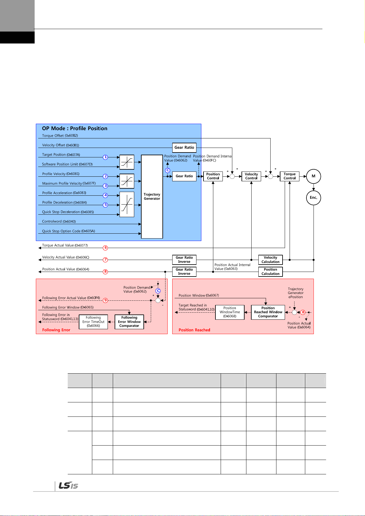
4. CiA402 Drive Profile
4.3.2 Profile Position Mode
Unlike the CSP mode receiving the target position, renewed at every PDO update cycle, from the upper
level controller, in the Profile Position (PP) mode, the drive generates a position profile internally to
operate up to the target position (0x607A) using the profile velocity (0x6081), acceleration (0x6083),
and deceleration (0x6084).
The block diagram of the PP mode is as follows:
4-8
Related Objects
Index
0x6040 - Controlword UINT RW Yes -
0x6041 - Statusword UINT RO Yes -
0x607A - Target Position DINT RW Yes UU
0x607D
Sub
Index
- Software Position Limit - - - -
0 Number of entries USINT RO No -
1 Min position limit DINT RW No UU
Name
Variable
type
Accessibility
PDO
assignment
Unit

4. CiA402 Drive Profile
2 Max position limit DINT RW No UU
0x607F - Maximum Profile Velocity UDINT RW Yes UU/s
0x6081 - Profile Velocity UDINT RW No UU/s
0x6083 - Profile Acceleration UDINT RW No UU/s
0x6084 - Profile Deceleration UDINT RW No UU/s
0x6085 - Quick Stop Deceleration UDINT RW No UU/s
2
2
2
0x60B1 - Velocity Offset DINT RW Yes UU/s
0x60B2 - Torque Offset INT RW Yes 0.1%
0x6062 - Position Demand Value DINT RO Yes UU
0x60FC - Position Demand Internal Value DINT RO Yes pulse
0x606C - Velocity Actual Value DINT RO Yes UU/s
0x606D - Velocity Window UINT RW No UU/s
0x606E - Velocity Window Time UINT RW No ms
0x6077 - Torque Actual Value INT RO Yes 0.1%
0x606C - Velocity Actual Value DINT RO Yes UU/s
0x6064 - Position Actual Value DINT RO Yes UU
0x6063 - Position Actual Internal Value DINT RO Yes pulse
4-9

4. CiA402 Drive Profile
Internal Block Diagram of PP Mode
4-10

4. CiA402 Drive Profile
You can use the following three position commands in Profile Position Mode:
Single set point
After reaching the target position, the drive sends a completion signal to the upper level controller
and receives a new command.
Change immediately
After receiving a new position command while driving to the target position, it drives to the new
position regardless of the existing target position.
Set of Set point
After receiving a new position command while driving to the target position, it subsequently drives
to the new target position after driving to the existing target position.
The three methods mentioned above can be set by a combination of the New setpoint bit (Controlword,
0x6040.4), the Change set immediately bit (Controlword, 0x6040.5), and the Change setpoint bit
(Controlword, 0x6040.9).
Single Set Point Driving Procedure
(1) Specify the target position (0x607A).
(2) Set the New setpoint bit to 1 and the Change set immediately bit to 0 to request the position
operation.
(3) The drive notifies the operator of its arrival at the target position with the Target reached bit
(Statusword, 0x6041.10). The drive can suspend where it is or perform a new position operation if
it receives the New set point bit.
4-11

4. CiA402 Drive Profile
Change Immediately Driving Procedure
(1) Specify the target position (0x607A).
(2) Set the New setpoint bit to 1 and the Change set immediately bit to 1 to request the position
operation.
(3) You can begin a new position operation (New setpoint) regardless of the previous target position.
The drive immediately moves to the new position.
(4) The drive notifies the operator of its arrival at the target position with the Target reached bit
(Statusword, 0x6041.10).
Set of Set Point Driving Procedure
4-12
(1) Specify the target position (0x607A).
(2) Set the New setpoint bit to 1 and the Change of Set point bit to 1 to request the position operation.
(3) After reaching the previous target position, the drive begins to move to the new position (New
setpoint).
(4) The drive notifies the operator of its arrival at the target position with the Target reached bit
(Statusword, 0x6041.10).

4. CiA402 Drive Profile
4.4 Velocity Control Mode
4.4.1 Cyclic Synchronous Velocity Mode
The Cyclic Synchronous Velocity (CSV) mode receives the target velocity (0x60FF), renewed at every
PDO update cycle, from the upper level controller, to control the velocity.
This mode allows the upper level controller to calculate the torque offset (0x60B2) corresponding the
torque feedforward and pass it to the drive.
The block diagram of the CSV mode is as follows:
Related Objects
Index
0x6040 - Controlword UINT RW Yes -
0x6041 - Statusword UINT RO Yes -
0x60FF - Target Velocity DINT RW Yes UU/s
0x6084 - Profile Deceleration UDINT RW No UU/s
0x6085 - Quick Stop Deceleration UDINT RW No UU/s
0x60B1 - Velocity Offset DINT RW Yes UU/s
0x60B2 - Torque Offset INT RW Yes 0.1%
0x606B - Velocity Demand Value DINT RO Yes UU
0x606C - Velocity Actual Value DINT RO Yes UU/s
Sub
Index
Name
Variable
type
Accessibility
PDO
assignment
Unit
2
2
4-13

4. CiA402 Drive Profile
0x606D - Velocity Window UINT RW No UU/s
0x606E - Velocity Window Time UINT RW No ms
0x6077 - Torque Actual Value INT RO Yes 0.1%
0x606C - Velocity Actual Value DINT RO Yes UU/s
0x6064 - Position Actual Value DINT RO Yes UU
0x6063 - Position Actual Internal Value DINT RO Yes pulse
4-14

4. CiA402 Drive Profile
Internal Block Diagram of CSV Mode
0x60B1
Velocity Offset
[UU/s]
0x6085
Quick Stop Dec.
[UU/s^2]
0x605A
Quick Stop
Option Code
0x60B2
Torque Offset
[0.1%]
0x606C
Velocity Actual
Value [UU/s]
0x6077
Torque Actual
Value [0.1%]
Velocity
Limit
Function
Gear Ratio
Inverse
Positon
Calulation
0x60FF
Target Velocity
[UU/s]
Interpolate
Velocity
Command
0x6064
Position Actual
Value [UU]
Speed Feedback
Time
Filter
0x210B
Velocity
Calulation
0x606B
Velocity Demand
Value [UU/s]
Gear Ratio
0x6091:01
Motor
0x6091:02
Shaft
0x60BA or 0x60BC
Touch Probe 1/2
Positive Edge
Position Value[UU]
Torque
Feed-Forward
Gain
Filter
Speed Control
P Gain I Gain
0x2102
1
0x2106
2
0x60BB or 0x60BD
Position Value[UU]
0x210E
0x210F
0x2103
0x2107
Processing Acc./Dec.
Speed Command
Acc. Time 0x2301
Dec. Time 0x2302
S-curve Time 0x2303
Touch Probe 1/2
Negative Edge
Gear Ratio
Inverse
P/PI Gain Conversion
Torque
Speed
Following
Error
Current Control
P/PI
Mode
Acc.
0x2514Gain
Servo-Lock
Function
Select 0x2311
0x6063
Position Internal
Actual Value [pulse]
0x2114
0x2115
0x2116
0x2117
0x2118
Disturbance
Observer
Gain
0x2512
Filter
0x2513
0x6074
Torque Demand
Value [0.1%]
Adaptive Filter
function Select
Frequency
0x2501
1
0x2504
2
0x2507
3
0x250A
4
Gain Conversion
Mode
Time1
Time2
Waiting
Time1
Waiting
Time2
Notch Filter
0x2500
Width
0x2502
0x2505
0x2508
0x250B
Torque Command
Filter
0x2104
1
0x2108
2
Torque Limit
Select
Ext. Positive
Ext. Negative
Positive
Negative
Max.
0x2119
0x211A
0x211B
0x211C
0x211D
Depth
0x2503
0x2506
0x2509
0x250C
0x2110
0x2111
0x2112
0x60E0
0x60E1
0x6072
4-15

4. CiA402 Drive Profile
4.4.2 Profile Velocity Mode
Unlike the CSV mode receiving the target velocity, renewed at every PDO update cycle, from the upper
level controller, in the Profile Velocity (PV) mode, the drive generates a velocity profile internally up to
the target velocity (0x60FF) using the profile acceleration (0x6083) and deceleration (0x6084), in order
to control its velocity.
At this moment, the max. profile velocity (0x607F) limits the maximum velocity.
The block diagram of the PV mode is as follows:
4-16

4. CiA402 Drive Profile
Related Objects
Index
Sub
Index
Name
Variable
type
Accessibility
PDO
assignment
Unit
0x6040 - Controlword UINT RW Yes -
0x6041 - Statusword UINT RO Yes -
0x60FF - Target Velocity DINT RW Yes UU/s
0x607F - Maximum Profile Velocity UDINT RW Yes UU/s
0x6083 - Profile Acceleration UDINT RW No UU/s
0x6084 - Profile Deceleration UDINT RW No UU/s
0x6085 - Quick Stop Deceleration UDINT RW No UU/s
2
2
2
0x605A - Quick Stop Option Code INT RW No -
0x60B1 - Velocity Offset DINT RW Yes UU/s
0x60B2 - Torque Offset INT RW Yes 0.1%
0x606B - Velocity Demand Value DINT RO Yes UU/s
0x606C - Velocity Actual Value DINT RO Yes UU/s
0x606D - Velocity Window UINT RW No UU/s
0x606E - Velocity Window Time UINT RW No ms
0x6077 - Torque Actual Value INT RO Yes 0.1%
0x606C - Velocity Actual Value DINT RO Yes UU/s
0x6064 - Position Actual Value DINT RO Yes UU
0x6063 - Position Actual Internal Value DINT RO Yes pulse
4-17

4. CiA402 Drive Profile
Internal Block Diagram of PV Mode
4-18

4. CiA402 Drive Profile
4.5 Torque Control Modes
4.5.1 Cyclic Synchronous Torque Mode
The Cyclic Synchronous Torque (CST) mode receives the target torque (0x6071), renewed at every
PDO update cycle, from the upper level controller, to control the torque.
This mode allows the upper level controller to calculate the torque offset (0x60B2) corresponding the
torque feedforward and pass it to the drive.
The block diagram of the CST mode is as follows:
Related Objects
Index
0x6040 - Controlword UINT RW Yes -
0x6041 - Statusword UINT RO Yes -
0x6071 - Target Velocity INT RW Yes 0.1%
0x6072 - Maximum Torque UINT RW Yes 0.1%
0x607F - Maximum Profile Velocity UDINT RW Yes UU/s
0x60E0 - Positive Torque Limit Value UINT RW Yes 0.1%
0x60E1 - Negative Torque Limit Value UINT RW Yes 0.1%
0x60B2 - Torque Offset INT RW Yes 0.1%
Sub
Index
Name
Variable
type
Accessibility
PDO
assignment
Unit
4-19

4. CiA402 Drive Profile
0x6074 - Torque Demand Value INT RO Yes 0.1%
0x606C - Velocity Actual Value DINT RO Yes UU/s
0x606D - Velocity Window UINT RW No UU/s
0x606E - Velocity Window Time UINT RW No ms
0x6077 - Torque Actual Value INT RO Yes 0.1%
0x606C - Velocity Actual Value DINT RO Yes UU/s
0x6064 - Position Actual Value DINT RO Yes UU
0x6063 - Position Actual Internal Value DINT RO Yes pulse
Internal Block Diagram of CST Mode
4-20

4. CiA402 Drive Profile
4.5.2 Profile Torque Mode
Unlike the CST mode receiving the target torque, renewed at every PDO update cycle, from the upper
level controller, in the Profile Torque (PT) mode, the drive generates a torque profile internally up to the
target torque (0x6071) by the torque slope (0x6087), in order to control its torque.
At this moment, the torque applied to the motor is limited depending on the Positive/Negative Torque
Limit Value (0x60E0 and 0x60E1) and the Maximum Torque (0x6072) based on its driving direction.
The block diagram of the PT mode is as follows:
Related Objects
Index
0x6040 - Controlword UINT RW Yes -
0x6041 - Statusword UINT RO Yes -
0x6071 - Target Velocity INT RW Yes 0.1%
0x6072 - Maximum Torque UINT RW Yes 0.1%
0x607F - Maximum Profile Velocity UDINT RW Yes UU/s
0x6087 - Torque Slope UDINT RW Yes 0.1%/s
0x60E0 - Positive Torque Limit Value UINT RW Yes 0.1%
0x60E1 - Negative Torque Limit Value UINT RW Yes 0.1%
0x60B2 - Torque Offset INT RW Yes 0.1%
0x6074 - Torque Demand Value INT RO Yes 0.1%
Sub
Index
Name
Variable
type
Accessibility
PDO
assignment
Unit
0x606C - Velocity Actual Value DINT RO Yes UU/s
0x606D - Velocity Window UINT RW No UU/s
4-21

4. CiA402 Drive Profile
0x606E - Velocity Window Time UINT RW No ms
0x6077 - Torque Actual Value INT RO Yes 0.1%
0x606C - Velocity Actual Value DINT RO Yes UU/s
0x6064 - Position Actual Value DINT RO Yes UU
0x6063 - Position Actual Internal Value DINT RO Yes pulse
Internal Block Diagram of PT Mode
4-22

4. CiA402 Drive Profile
4.6 Homing
This drive provides its own homing function. The figure below represents the relationship between the
input and output parameters for the homing mode. You can specify the speed, acceleration, offset, and
homing method.
Homing Method
Homing Speeds
Position demand internal value (0x60FC)
Homing Acceleration
Home Offset
or position demand value (0x6062)
As shown in the figure below, you can set the offset between the home position and the zero position of
the machine using the home offset. The zero position indicates a point whose Actual Position Value
(0x6064) is zero (0).
4-23

4. CiA402 Drive Profile
4.6.1 Homing Method
The drive supports the following homing methods (0x6098):
Homing Method
(0x6098)
1
2
7,8,9,10
11,12,13,14
24
28
33
34
Details
The drive returns to the home position with the negative limit switch (NOT) and the Index
(Z) pulse while driving in the reverse direction.
The drive returns to the home position with the positive limit switch (POT) and the Index
(Z) pulse while driving in the forward direction.
The drive returns to the home position with the home switch (HOME) and the Index (Z)
pulse while driving in the forward direction. When the positive limit switch (POT) is input
during homing, the drive will switch its driving direction.
The drive returns to the home position with the home switch (HOME) and the Index (Z)
pulse while driving in the reverse direction. When the negative limit switch (NOT) is input
during homing, the drive will switch its driving direction.
The drive returns to the home position with the home switch (HOME) while driving in the
forward direction. When the positive limit switch (POT) is input during homing, the drive will
switch its driving direction.
The drive returns to the home position with the home switch (HOME) while driving in the
reverse direction. When the negative limit switch (NOT) is input during homing, the drive
will switch its driving direction.
The drive returns to the home position with the Index (Z) pulse while driving in the reverse
direction.
The drive returns to the home position with the Index (Z) pulse while driving in the forward
direction.
35 Sets the current position as the origin.
-1
-2
-3
-4
-5 During reverse operation, the motor is returned to the orign by Home switch
-6 During foward operation, the motor is returned to the orign by Home switch
The drive returns to the home position with the negative stopper and the Index (Z) pulse
while driving in the reverse direction.
The drive returns to the home position with the positive stopper and the Index (Z) pulse
while driving in the forward direction.
The drive only returns to the home position with the negative stopper while driving in the
reverse direction.
The drive only returns to the home position with the positive stopper while driving in the
forward direction.
4-24

4. CiA402 Drive Profile
Related Objects
Index
0x6040 - Controlword UNIT RW Yes -
0x6041 - Statusword UINT RO Yes -
0x607C - Home Offset DINT RW No UU
0x6098 - Homing Method SINT RW Yes -
0x6099
0x609A - Homing Acceleration UDINT RW Yes UU/s
Sub
Index
- Homing Speed - - - -
0 Number of entries USINT RO No -
1 Speed during search for switch UDINT RW Yes UU/s
2 Speed during search for zero UDINT RW Yes UU/s
Name
Variable
type
Accessibility
PDO
assignment
Unit
2
4-25

4. CiA402 Drive Profile
Homing Methods 1 and 2
Reverse ( CW)
Forward (CCW)
For homing using the Homing Method 1, the velocity profile according to the sequence is as follows.
See the details below:
(A) The initial driving direction is reverse (CW), and the drive operates at the Switch Search Speed.
(B) When the negative limit switch (NOT) is turned on, the drive switches its direction to the forward direction (CCW),
decelerating to the Zero Search Speed.
(C) While operating at the Zero Search Speed, the drive detects the first index pulse to move to the index position (Home).
4-26

4. CiA402 Drive Profile
Methods 7, 8, 9, and 10
Reverse ( CW) Forward (CCW)
For homing using the Homing Method 7, the velocity profile according to the sequence is as follows.
The sequence depends on the relationship between the load position and the Home switch at homing,
which is categorized into three cases as below. For more information, see the details below:
(1) At the start of homing, when the Home switch is OFF and the limit is not met during
operation
(A) The initial driving direction is forward (CCW), and the drive operates at the Switch Search Speed.
(B) When the Positive Home Switch is turned on, the drive will decelerate to the Zero Search Speed, and then switches its
direction to the reverse direction (CW).
(C) While operating at the Zero Search Speed, the drive detects the first index pulse to move to the index position (Home).
(2) At the start of homing, when the Home switch is ON
4-27

4. CiA402 Drive Profile
(A) Since the Home signal is on, the drive will operate at the Switch Search Speed in the direction of the Positive Home
Switch (CCW). It might not reach the Switch Search Speed depending on the start position of homing.
(B) When the Home switch is turned off, the drive will decelerate to Zero Search Speed, and then continue to operate.
(C) While operating at the Zero Search Speed, the drive detects the first index pulse to move to the index position (Home).
(3) At the start of homing, when the Home switch is OFF and the limit is met during
operation
(A) The initial driving direction is forward (CCW), and the drive operates at the Switch Search Speed.
(B) When the positive limit switch (POT) is turned on, the drive will decelerate down to stop, and then operate at the Switch
Search Speed in the reverse direction (CW).
(C) When the Positive Home switch is turned off, the drive will decelerate to Zero Search Speed, and then continue to
operate.
(D) While operating at the Zero Search Speed, the drive detects the first index pulse to move to the index position (Home).
The methods from 8 to 10 are nearly identical to the method 7 in terms of the homing sequence. The only differences are the
initial driving direction and Home switch polarity.
4-28
The Positive Home Switch is determined by the initial driving direction. A Home switch which is
encountered in the initial driving direction becomes the Positive Home Switch.

4. CiA402 Drive Profile
Initial driving direction: Forward (CCW)
Initial driving direction: Reverse (CCW)
Methods 11, 12, 13, and 14
Reverse ( CW) Forward (CW)
For homing using the Homing Method 14, the velocity profile according to the sequence is as follows.
The sequence depends on the relationship between the load position and the Home switch at homing,
which is categorized into three cases as below. For more information, see the details below:
4-29

4. CiA402 Drive Profile
(1) At the start of homing, when the Home switch is OFF and the limit is not met during
operation
(A) The initial driving direction is reverse (CW), and the drive operates at the Switch Search Speed.
(B) When the Negative Home switch is turned off, the drive will decelerate to Zero Search Speed, and then continue to
operate.
(C) While operating at the Zero Search Speed, the drive detects the first index pulse to move to the index position (Home).
(2) At the start of homing, when the Home switch is ON
(A) Since the Home signal is on, the drive will operate at the Switch Search Speed in the direction of the Negative Home
Switch (CW). It might not reach the Switch Search Speed depending on the start position of homing.
(B) When the Home switch is turned off, the drive will decelerate to Zero Search Speed, and then continue to operate.
(C) While operating at the Zero Search Speed, the drive detects the first index pulse to move to the index position (Home).
4-30

4. CiA402 Drive Profile
(3) At the start of homing, when the Home switch is OFF and the limit is met during
operation
(A) The initial driving direction is reverse (CW), and the drive operates at the Switch Search Speed.
(B) When the negative limit switch (NOT) is turned on, the drive will decelerate down to stop, and then operate at the Switch
Search Speed in the forward direction (CCW).
(C) When the Negative Home Switch is turned on, the drive will decelerate to the Zero Search Speed, and then switches its
direction to the reverse direction (CW).
(D) While operating at the Zero Search Speed, the drive detects the first index pulse to move to the index position (Home).
The methods from 11 to 13 are nearly identical to the method 14 in terms of the homing sequence. The only differences are
the initial driving direction and Home switch polarity.
Method 24
Reverse ( CW) Forward (CCW)
The initial driving direction is forward (CCW), and a point where the Positive Home Switch is turned on becomes the Home
position.
4-31

4. CiA402 Drive Profile
Method 28
Reverse ( CW)
Forward (CCW)
The initial driving direction is reverse (CW), and a point where the Positive Home Switch is turned on becomes the Home position.
Method 33 and 34
Reverse ( CW)
Forward (CCW)
The initial driving direction is reverse (CW) for the method 33, and forward (CCW) for the method 34. The drive detects the index
pulse at the Zero Search Speed.
4-32
 Loading...