


• SV-iS7 is the official name for the iS7 series inverters.
• This operation manual is intended for users with basic knowledge of electricity and electric
devices.
• Keep this manual near the product for future reference whenever setting change, maintenance
or service is required.
• Ensure that the field operators and service engineers can easily access this manual.
• For detailed information about the optional extension boards, including the specifications and
the requirements for installation and operation, refer to the instruction manuals that are
supplied with the products.

Safety Information
Indicates an imminently hazardous situation which, if not avoided, will result in severe injury or
death.
Indicates a potentially hazardous situation which, if not avoided, could result in injury or death.
Indicates a potentially hazardous situation which, if not avoided, could result in minor injury or
property damage.
• Do not open the cover of the equipment while it is on or operating. Likewise, do not operate the
inverter while the cover is open. Exposure of the high voltage terminals or the charging area to
the external environment may result in an electric shock. Do not remove any covers or touch
the internal circuit boards (PCBs) or electrical contacts on the product when the power is on or
during operation. Doing so may result in serious injury, death, or serious property damage.
• Do not open the cover of the equipment, even when the power supply to the inverter has been
turned off, unless it is necessary for maintenance or regular inspection. Opening the cover may
result in an electric shock even when the power supply is off.
• The equipment may hold a charge long after the power supply has been turned off. Use a
multi-meter to make sure that the remaining voltage is below 30 VDC before working on the
inverter, motor, or motor cable.
Safety Information
Read and follow all safety instructions in this manual precisely to avoid unsafe operating
conditions, property damage, personal injury, or death.
Safety symbols in this manual
Safety information

iii
Safety Information
• This equipment must be grounded for safe and proper operation.
• Do not supply power to a faulty inverter. If you find that the inverter is faulty, disconnect the
power supply and have the inverter professionally repaired.
• The inverter becomes hot during operation. Avoid touching the inverter until it has cooled to
avoid burns.
• Do not allow foreign objects, such as screws, metal chips, debris, water, or oil, to get inside the
inverter. Allowing foreign objects inside the inverter may cause the inverter to malfunction or
result in a fire.
• Do not operate the inverter with wet hands. Doing so may result in electric shock.
• Do not modify the interior workings of the inverter. Doing so will void the warranty.
• Do not use cables with damages or cracks on the protective insulation when wiring the inverter.
Damaged insulation may cause misoperation, an electric shock or a fire.
• Do not place heavy objects on top of electric cables. Doing so may damage the cable and result
in an electric shock.
Note
The maximum allowed prospective short-circuit current at the input power connection is defined in
IEC 60439-1 as 100 kA. The drive is suitable for use in a circuit capable of delivering not more than
100 kA RMS at the drive’s maximum rated voltage.


1
Table of contents
Table of Contents
1
About the Product ........................................................................................................ 1
1.1
Preparing for Installation and Operation .......................................................... 1
1.1.1
Identifying the Product ................................................................................. 1
1.1.2
Checking the Product for Defects or Damage .......................................... 3
1.1.3
Preparing the Product for Installation and Operation ........................... 3
1.1.4
Installing the Product .................................................................................... 3
1.1.5
Connecting the Cables ................................................................................... 3
1.2
Part Names .............................................................................................................. 4
1.2.1
Interior and Exterior View (IP 21 Model Types Less than 22 kW [200 V]
/ Less than 75 kW [400 V]) ............................................................................ 4
1.2.2
Interior and Exterior View (IP 54 Model Types Less than 22 kW
[200/400 V]) ..................................................................................................... 5
1.2.3
Interior and Exterior View (Model Types 30 kW and up [200 V] / 90
kW and up [400 V]) ........................................................................................ 6
2
Technical Specifications .............................................................................................. 7
2.1
Input and Output Specifications 200 V Class (0.75–22 kW) ........................... 7
2.2
Input and Output Specifications 200 V Class (30–75 kW)............................... 8
2.3
Input and Output Specifications 400 V Class (0.75–22 kW) ........................... 9
2.4
Input and Output Specifications 400 V Class (30–160 kW) .......................... 10
2.5
Input and Output Specifications 400 V Class (185–375 kW) ........................ 11
2.6
Product Specification Details ............................................................................. 12
2.6.1
Control ........................................................................................................... 12
2.6.2
Operation ...................................................................................................... 12
2.6.3
Protection Function ..................................................................................... 14
2.6.4
Structure and Operating Environment Control .................................... 14
3
Installing the Inverter .............................................................................................. 16
3.1
Installation Considerations ................................................................................ 16
3.2
Selecting and Preparing a Site for Installation ............................................... 17
3.3
Exterior and Dimensions (UL Enclosed Type 1, IP21 Type) ......................... 21
3.4
Exterior and Dimensions (UL Enclosed Type 12, IP54 Type) ....................... 35
3.5
Frame Dimensions and Weight (UL Enclosed Type 1, IP 21 Type) ............. 39
3.6
Frame Dimensions and Weight (UL Enclosed Type 12, IP54 Type)............ 41
3.7
Installation Procedures for UL Enclosed Type12 and IP54 Type Products
42

Table of contents
2
3.7.1
Disassembling the Keypad Cover and Keypad ...................................... 42
3.7.2
Disassembling the IP54 Front Cover ....................................................... 43
3.7.3
Mounting the Inverter ................................................................................ 44
3.7.4
Connecting the Power Cables ................................................................... 45
3.7.5
Reassembling the IP54 Front Cover and the Keypad .......................... 46
4
Connecting the Cables.............................................................................................. 48
4.1
Removing the Front Cover for Cable Connection.......................................... 48
4.1.1
IP 21 Type Products ..................................................................................... 48
4.1.2
IP 54 Type Products ..................................................................................... 50
4.1.3
90–375 kW, 400 V and 30–75 kW, 200 V Products ................................ 51
4.2
Activating and Deactivating the Built-in EMC Filter ....................................... 52
4.2.1
Up to 7.5 kW Inverters ................................................................................ 52
4.2.2
11–22 kW Inverters...................................................................................... 54
4.3
Precautions for Wiring the Inverter .................................................................. 56
4.4
Ground Connection ............................................................................................. 57
4.5
Terminal Wiring Diagram ................................................................................... 58
4.5.1
Up to 7.5 kW Inverters ................................................................................ 58
4.5.2
11–22 kW Inverters...................................................................................... 58
4.5.3
30–75 kW Inverters...................................................................................... 58
4.5.4
90–160 kW Inverters ................................................................................... 58
4.5.5
185–220 kW Inverters ................................................................................. 59
4.5.6
280–375 kW Inverters ................................................................................. 59
4.6
Connecting Cables to the Power Terminal Block .......................................... 60
4.6.1
0.75–22 kW (200 V/400 V) ........................................................................... 60
4.6.2
30–75 kW (200 V/400 V) .............................................................................. 61
4.6.3
90–160 kW (400 V)........................................................................................ 62
4.6.4
185–220 kW (400 V) ..................................................................................... 63
4.6.5
280–375 kW (200 V/400 V) .......................................................................... 64
4.7
Specifications of the Power Terminal Block and Exterior Fuse ................... 65
4.7.1
Cable Length between the Inverter and the Motor ............................. 66
4.7.2
Protective Measures for the Inverter and the Motor ........................... 67
4.8
Control Terminal Wiring for iS7 Inverters Rated for Up To 22 kW ............. 68
4.8.1
NPN Mode (Sink) .......................................................................................... 69
4.8.2
PNP Mode (Source) ..................................................................................... 69
4.8.3
0.75–22 kW (Basic I/O) ................................................................................ 70
4.9
Control Terminal Wiring for iS7 Inverters Rated for 30 kW or More ......... 71
4.10
Terminal Inputs for Inverter Operation........................................................... 72
4.11
Cable Specifications for Control Block Wiring ................................................ 74

3
Table of contents
4.12
Setting the Built-in Surge Filter .......................................................................... 75
4.13
Activating or Deactivating the Surge Filter ..................................................... 76
4.13.1
iS7 30–75KW (400 V) Inverters .................................................................. 76
4.13.2
iS7 90–375 kW (400V) Inverters ................................................................ 76
4.14
Post-Installation Checklist................................................................................... 78
4.15
Test Run .................................................................................................................. 79
4.15.1
Entering Easy Start Mode ........................................................................... 79
4.15.2
Setting the Basic Parameters in Easy Start Mode ................................. 80
4.15.3
Checking the Inverter Operation ............................................................. 81
5
Using the Keypad ....................................................................................................... 82
5.1
About the Keypad ................................................................................................. 82
5.1.1
Dimensions ................................................................................................... 82
5.1.2
Key Functions ............................................................................................... 83
5.1.3
Display Items ................................................................................................ 84
5.1.4
Display Item List ........................................................................................... 84
5.2
Menu Items ........................................................................................................... 87
5.2.1
Parameter Mode .......................................................................................... 88
5.2.2
User & Macro Mode .................................................................................... 89
5.3
Navigating Modes ................................................................................................ 90
5.3.1
Mode Navigation at the Factory Default ................................................. 90
5.3.2
Mode Navigation with User/Macro Mode and Trip Mode .................. 91
5.4
Navigating Modes and Parameters ................................................................. 93
5.4.1
Group Navigation in Parameter mode ................................................... 93
5.4.2
Group Shift in User & Macro Mode .......................................................... 95
5.5
Navigating through Codes (Function Items) .................................................. 96
5.5.1
Code Navigation in Monitor Mode .......................................................... 96
5.5.2
Code Navigation (function items) in Other Modes and Groups ........ 97
5.5.3
Code Navigation Using Jump Code.......................................................... 98
5.6
Setting Parameters ............................................................................................ 100
5.6.1
Parameter Settings in Monitor Mode.................................................... 100
5.6.2
Parameter Settings in Other Modes and Groups ............................... 101
5.7
Monitoring Operating Status ........................................................................... 102
5.7.1
Using Monitor Mode ................................................................................. 102
5.7.2
Monitoring Items ....................................................................................... 103
5.7.3
Using the Status Display........................................................................... 104
5.8
Monitoring Faults ............................................................................................... 105
5.8.1
Faults during Inverter Operation ........................................................... 105
5.8.2
Multiple Faults at a Time during Inverter Operation ......................... 106

Table of contents
4
5.8.3
Saving and Monitoring the Fault Trip History ...................................... 106
5.9
Initializing Parameters ...................................................................................... 108
6
Basic Functions ......................................................................................................... 110
6.1
Setting Frequency References ......................................................................... 110
6.1.1
Keypad as the Source (KeyPad-1 setting) ............................................. 111
6.1.2
Keypad as the Source (KeyPad-2 setting) ............................................. 111
6.1.3
V1 Terminal as the Source ....................................................................... 111
6.1.4
Setting a Frequency Reference Using an I/O Expansion Module
(Terminal V2/I2) ........................................................................................ 121
6.1.5
Setting a Frequency with Pulse Input (with an optional encoder
module) ...................................................................................................... 123
6.1.6
Setting a Frequency Reference via RS-485 Communication............. 125
6.2
Frequency Hold by Analog Input .................................................................... 126
6.3
Changing the Displayed Units (Hz↔Rpm) .................................................... 127
6.4
Setting Multi-Step Frequency........................................................................... 127
6.5
Command Source Configuration .................................................................... 130
6.5.1
The Keypad as a Command Input Device ............................................ 130
6.5.2
The Terminal Block as a Command Input Device (Fwd/Rev run
commands) ................................................................................................ 131
6.5.3
The Terminal Block as a Command Input Device (Run and Rotation
Direction Commands) ............................................................................. 132
6.5.4
RS-485 Communication as a Command Input Device ....................... 133
6.6
Forward or Reverse Run Prevention .............................................................. 133
6.7
Power-on Run ...................................................................................................... 134
6.8
Setting Acceleration and Deceleration Times .............................................. 135
6.8.1
Acc/Dec Time Based on Maximum Frequency .................................... 135
6.8.2
Acc/Dec Time Based on Operation Frequency .................................... 137
6.8.3
Multi-Step Acc/Dec Time Configuration ................................................ 138
6.8.4
Configuring Acc/Dec Time Switch Frequency ...................................... 139
6.9
Output Voltage Setting ..................................................................................... 141
7
Troubleshooting and Maintenance .................................................................... 142
7.1
7.2
7.3
7.4
Protection Functions .......................................................................................... 142
7.1.1
Protection from Output Current and Input Voltage .......................... 142
7.1.2
Abnormal Circuit Conditions and External Signals ............................. 143
7.1.3
Keypad and Optional Expansion Modules ........................................... 145
Warning Messages ............................................................................................ 146
Troubleshooting Fault Trips ............................................................................. 147
Replacing the Cooling Fan ................................................................................ 150

5
Table of contents
7.4.1
Products Rated below 7.5 kW ................................................................. 150
7.4.2
Products Rated at 11-15 kW 200 V/400 V and 18.5-22 kW 400 V ..... 150
7.4.3
Products Rated at more than 30 kW (200 V) / 90 kW (400 V), and 18.5–
22 kW (200 V) / 30–75 kW (200/400 V) .................................................. 151
7.5
Daily and Regular Inspection Lists .................................................................. 152
8
Table of Functions ................................................................................................... 155
8.1
Parameter Mode – DRV Group (DRV) ........................................................ 155
8.2
Parameter Mode – Basic Function Group (BAS) ...................................... 158
8.3
Parameter Mode – Expansion Function Group (PARADV) ..................... 162
8.4
Parameter Mode – Control Function Group (CON) ................................. 166
8.5
Parameter Mode – Input Terminal Block Function Group (IN) ............ 172
8.6
Parameter Mode – Output Terminal Block Function Group (OUT) ..... 176
8.7
Parameter Mode – Communication Function Group (COM) ................ 180
8.8
Parameter Mode – Applied Function Group (APP) .................................. 183
8.9
Parameter Mode – Auto Sequence Operation Group (AUT) ................. 186
8.10
Parameter Mode – Option Module Function Group (APO) ................... 189
8.11
Parameter Mode – Protective Function Group (PRT) ............................. 192
8.12
Parameter Mode – 2nd Motor Function Group (M2) ............................. 195
8.13
Trip Mode (TRP Current (or Last-x)) ................................................................ 196
8.14
Config Mode (CNF) ............................................................................................. 196
8.15
User/Macro Mode – Draw Operation Function GroupMC1 .................. 199
8.16
User/Macro mode – Traverse Operation Function Group (MC2) ........ 200
9
Peripheral Devices ................................................................................................... 201
9.1
Wiring Switch, Electronic Contactor, and Reactor Specifications ............. 202
9.1.1
Wiring Switch, Short Circuit Switch, and Electronic Contactor ......... 202
9.1.2
Reactors ....................................................................................................... 204
9.1.3
Dynamic Braking Unit (DBU) and Resistor ........................................... 207
9.1.4
DB Unit Dimensions .................................................................................. 211
9.1.5
Indicators on the DB unit ......................................................................... 217
9.1.6
DB Resistors ................................................................................................ 217
9.1.7
DB Resistor Dimensions ........................................................................... 219
9.1.8
Keypad Extension Cable for Remote Control (Optional) ................... 221
10
Safety Funtion STO(Safe Torque Off) .................................................................. 224
10.1
Safety Standard Product ................................................................................... 224
10.2
About the Safety Function ................................................................................ 224
10.2.1
Safety Function Wiring Diagram ............................................................ 225

Table of contents
6
10.2.2
Installing the Safety Board to 0.75–160 kW Product .......................... 226
10.2.3
Installing the Safety Board to 185–375 kW Product ........................... 226
10.2.4
Safety Function Terminal Description ................................................... 227
10.2.5
Cable Specification for Signal Terminal Block Wiring ......................... 227
11
Marine Certification ................................................................................................ 228
11.1
DNV (Det Norske Veritas) Marine Certification Details .............................. 228
11.2
Bureau Veritas (Marine & Offshore Division) Marine Certification Details
228
11.3
ABS Marine Certification Details...................................................................... 228
11.4
Marine Certification Models for SV-iS7 Products ......................................... 229
12
Using a Single Phase Power Source .................................................................... 231
12.1
Single Phase Rating ........................................................................................... 231
12.2
Power(HP), Input Current and Output Current ........................................... 232
12.3
Input Frequency and Voltage Tolerance ....................................................... 233
12.4
Wiring and Peripheral Device .......................................................................... 234
12.5
Other Considerations ........................................................................................ 237
Product Warranty ............................................................................................................ 238
Index ................................................................................................................................... 241

About the Product
About the
Product
1
1 About the Product
This chapter provides details on product identification and part names. To install the inverter
correctly and safely, carefully read and follow the instructions.
1.1 Preparing for Installation and Operation
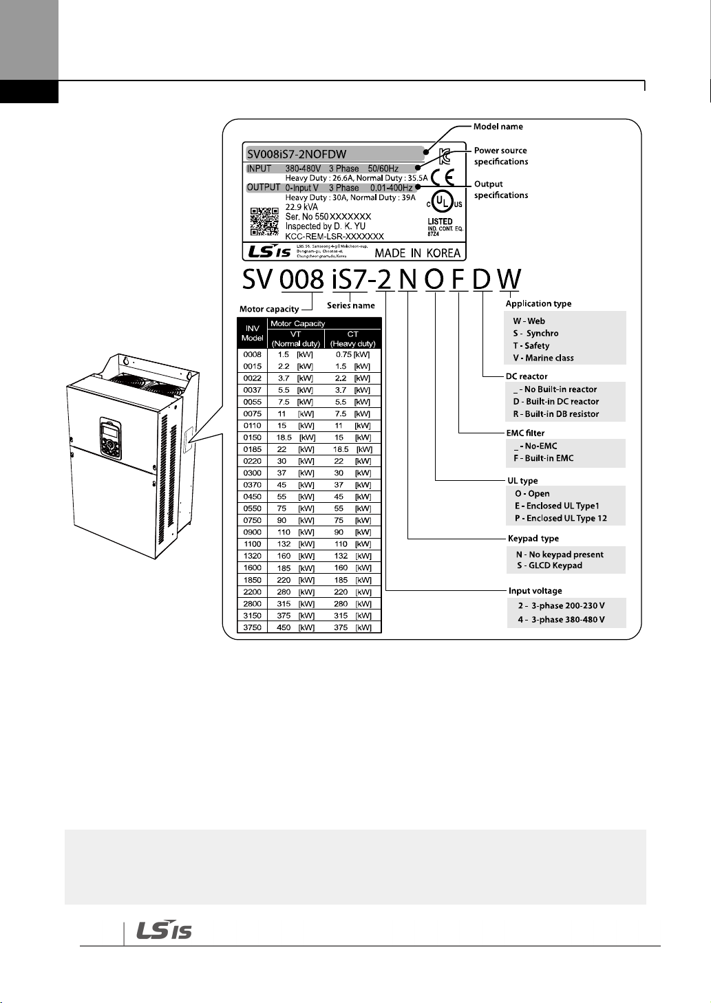
1.1.1 Identifying the Product
Check the product name, open the packaging, and then confirm that the product is free from
defects. Contact your supplier if you have any issues or questions about your product.
The iS7 inverter is manufactured in a range of product groups based on drive capacity and
power source specifications. The product name and specifications are detailed on the rating
plate. Check the rating plate before installing the product and make sure that the product
meets your requirements.
2
About the Product
Note
The iS7 75/90 kW, 400 V inverters satisfy the EMC standard EN61800-3 without the installation of
optional EMC filters.
Note1) Optional conduit parts are available for the Enclosed UL Type 1 models (0.75–75 kW
products).
Note2) Optional built-in DCR is available for the Web application models (0.75–375 kW / type
2/4 products).
Note3) To use safety function, please buy 0.75-160kW product including safety option. However
185-375kW product users have to buy safety option and apply to standard products because
safety option is not included.

About the Product
About the
Product
3
1.1.2 Checking the Product for Defects or Damage
If you suspect that the product has been mishandled or damaged in any way, contact the LSIS
Customer Support center with the phone numbers listed on the back cover of this manual.
1.1.3 Preparing the Product for Installation and Operation
Preparation steps for installation and operation may slightly vary by product type and
application. Refer to the manual and prepare the product accordingly.
1.1.4 Installing the Product
Refer to the installation section of this manual and install the product correctly considering the
installation and operating conditions at the installation location, such as installation clearances,
to prevent premature deterioration or performance loss.
1.1.5 Connecting the Cables
Connect the power input/output and signal cables to the terminal block according to the
instructions provided in this manual. Ensure that all the cables are connected correctly before
supplying power to the product. Incorrect cable connections may damage the product.

4
About the Product
1.2 Part Names
The illustration below displays part names. Details may vary between product groups.
1.2.1 Interior and Exterior View (IP 21 Model Types Less than 22 kW
[200 V] / Less than 75 kW [400 V])

About the Product
About the
Product
5
1.2.2 Interior and Exterior View (IP 54 Model Types Less than 22 kW
[200/400 V])

6
About the Product
Note
Refer to the installation manual provided with the optional module products before installing
communication modules in the inverter.
1.2.3 Interior and Exterior View (Model Types 30 kW and up [200 V]
/ 90 kW and up [400 V])

Technical Specifications
Technical
Specifications
7
Model SV xxx iS7–2x
0008
0015
0022
0037
0055
0075
0110
0150
0185
0220
Applied
Motor
Normal load
HP 2 3 5 7.5
10
15
20
25
30
40
kW
1.5
2.2
3.7
5.5
7.5
11
15
18.5
22
30
Heavy load
HP 1 2 3 5
7.5
10
15
20
25
30
kW
0.75
1.5
2.2
3.7
5.5
7.5
11
15
18.5
22
Rated
output
Rated Capacity (kVA)
1.9
3.0
4.5
6.1
9.1
12.2
17.5
22.9
28.2
33.5
Rated
Current
(A)
Normal
load
8
12
16
24
32
46
60
74
88
124
Heavy
load
5 8 12
16
24
32
46
60
74
88
Output Frequency
0–400 Hz (Sensorless-1: 0–300 Hz, Sensorless-2, Vector: 0.1–120
Hz)
Output Voltage (V)
3-Phase 200–230 V
Rated
input
Working Voltage (V)
3-Phase 200–230 VAC (-15%–+10%)
Input Frequency
50–60 Hz (5%)
Rated
Current
(A)
Normal
load
6.8
10.6
14.9
21.3
28.6
41.2
54.7
69.7
82.9
116.1
Heavy
load
4.3
6.9
11.2
14.9
22.1
28.6
44.3
55.9
70.8
85.3
2 Technical Specifications
2.1 Input and Output Specifications 200 V Class (0.75–
22 kW)
• Only the heavy duty ratings apply to model types without a built-in DC resistor (NON-DCR).
• The standard used for 200 V inverters is based on a 220 V supply voltage.
• The rated output current is limited based on the carrier frequency set at CON-04.
• The output frequency is limited to 0–300 Hz if DRV-09 (control mode) is set to “3
(Sensorless-1),” and to 0–120 Hz if DRV-09 (control mode) is set to “4 (Sensorless-3).”
• The maximum output voltage cannot exceed the input voltage of the power source.

Technical Specifications
8
Model SV xxx iS7–2x
0300
0370
0450
0550
0750
Applied
Motor
Normal load
HP
50
60
75
100
120
kW
37
45
55
75
90
Heavy load
HP
40
50
60
75
100
kW
30
37
45
55
75
Rated
output
Rated Capacity (kVA)
46
57
69
84
116
Rated
Current
(A)
Normal
load
146
180
220
288
345
Heavy
load
116
146
180
220
288 Output Frequency
0–400 Hz (Sensorless-1: 0–300 Hz, Sensorless-2, Vector: 0.1–120
Hz)
Output Voltage (V)
3-Phase 200–230 V
Rated
input
Working Voltage (V)
3-Phase 200–230 VAC (-15%–+10%)
Input Frequency
50–60 Hz (5%)
Rated
Current
(A)
Normal
load
152
190
231
302
362
Heavy
load
121
154
191
233
305
2.2 Input and Output Specifications 200 V Class (30–
75 kW)
• The standard motor capacity is based on a standard 4-pole motor.
• The standard used for 200 V inverters is based on a 200 V supply voltage.
• The rated output current is limited based on the carrier frequency set at CON-04.
• The output frequency is limited to 0–300 Hz if DRV-09 (control mode) is set to “3
(Sensorless-1),” and to 0–120 Hz if DRV-09 (control mode) is set to “4 (Sensorless-3).”
• The maximum output voltage cannot exceed the input voltage of the power source.

Technical Specifications
Technical
Specifications
9
Model SV xxx iS7–2x
0008
0015
0022
0037
0055
0075
0110
0150
0185
0220
Applied
Motor
Normal load
HP 2 3 5 7.5
10
15
20
25
30
40
kW
1.5
2.2
3.7
5.5
7.5
11
15
18.5
22
30
Heavy load
HP 1 2 3 5
7.5
10
15
20
25
30
kW
0.75
1.5
2.2
3.7
5.5
7.5
11
15
18.5
22
Rated
output
Rated Capacity
(kVA)
1.9
3.0
4.5
6.1
9.1
12.2
18.3
22.9
29.7
34.3
Rated
Current
(A)
Normal
load
4 6 8
12
16
24
30
39
45
61
Heavy
load
2.5 4 6 8 12
16
24
30
39
45
Output Frequency
0–400 Hz (Sensorless-1: 0–300Hz, Sensorless-2, Vector: 0.1–120Hz)
Output Voltage (V)
3-Phase 380–480 V
Rated
input
Working Voltage (V)
3-Phase 380–480 VAC (-15%–+10%)
Input Frequency
50–60 Hz (5%)
Rated
Current
(A)
Normal
load
3.7
5.7
7.7
11.1
14.7
21.9
26.4
35.5
41.1
55.7
Heavy
load
2.2
3.6
5.5
7.5
11.0
14.4
22.0
26.6
35.6
41.6
2.3 Input and Output Specifications 400 V Class (0.75–
22 kW)
• Only the heavy duty ratings apply to model types without a built-in DC resistor (NON- DCR).
• The standard motor capacity is based on a standard 4-pole motor.
• The standard used for 400 V inverters is based on a 440 V supply voltage.
• The rated output current is limited based on the carrier frequency set at CON-04.
• The output frequency is limited to 0-300 Hz if DRV-09 (control mode) is set to “3 (Sensorless-
1),” and to 0-120 Hz if DRV-09 (control mode) is set to “4 (Sensorless-3).”
• The maximum output voltage cannot exceed the input voltage of the power source.

Technical Specifications
10
Model SV xxx iS7–2x
0300
0370
0450
0550
0750
0900
1100
1320
1600
Applied
Motor
Normal load
HP
50
60
75
100
120
150
180
225
250
kW
37
45
55
75
90
110
132
160
185
Heavy load
HP
40
50
60
75
100
120
150
180
225
kW
30
37
45
55
75
90
110
132
160
Rated
output
Rated Capacity
(kVA)
46
57
69
84
116
139
170
201
248
Rated
Current
(A)
Normal
load
75
91
110
152
183
223
264
325
370
Heavy
load
61
75
91
110
152
183
223
264
325 Output Frequency
0–400 Hz (Sensorless-1: 0–300 Hz, Sensorless-2, Vector: 0.1–120
Hz)
Output Voltage (V)
3-Phase 380–480 V
Rated
input
Working Voltage (V)
3-Phase 380–480 VAC (-15%–+10%)
Input Frequency
50–60 Hz (5%)
Rated
Current
(A)
Normal
load
67.5
81.7
101.8
143.6
173.4
212.9
254.2
315.3
359.3
Heavy
load
55.5
67.9
82.4
102.6
143.4
174.7
213.5
255.6
316.3
2.4 Input and Output Specifications 400 V Class (30–
160 kW)
• The standard used for 400 V inverters is based on a 440 V supply voltage.
• The rated output current is limited based on the carrier frequency set at CON-04.
• The output frequency is limited to 0–300 Hz if DRV-09 (control mode) is set to “3
(Sensorless-1),” and to 0–120 Hz if DRV-09 (control mode) is set to “4 (Sensorless-3).”
• The maximum output voltage cannot exceed the input voltage of the power source.

Technical Specifications
Technical
Specifications
11
Model SV xxx iS7–2x
1850
2200
2800
3150
3750
Applied
Motor
Normal load
HP
300
375
420
500
600
kW
220
280
315
375
450
Heavy load
HP
250
300
375
420
500
kW
185
220
280
315
375
Rated
output
Rated Capacity
(kVA)
286
329
416
467
557
Rated
Current
(A)
Normal
load
432
547
613
731
877
Heavy
load
370
432
547
613
731
Output Frequency
0–400 Hz (Sensorless-1: 0–300 Hz, Sensorless-2, Vector: 0–120 Hz)
Output Voltage (V)
3-Phase 380–480 V
Rated
input
Working Voltage (V)
3-Phase 380–480 VAC (-15%–+10%)
Input Frequency
50–60 Hz (5%)
Rated
Current
(A)
Normal
load
463
590
673
796
948
Heavy
load
404
466
605
674
798
Note
The maximum allowed prospective short circuit current at the input power connection is defined in
IEC 60439-1 as 100 kA. The drive is suitable for use in a circuit capable of delivering not more than
100 kA RMS at the drive’s maximum rated voltage.
2.5 Input and Output Specifications 400 V Class (185–
375 kW)
• The standard motor capacity is based on a standard 4-pole motor.
• The standard used for 400 V inverters is based on a 440 V supply voltage.
• The rated output current is limited based on the carrier frequency set at CON-04.
• The output frequency is limited to 0–300 Hz if DRV-09 (control mode) is set to “3
(Sensorless-1),” and to 0–120 Hz if DRV-09 (control mode) is set to “4 (Sensorless-3).”
• The maximum output voltage cannot exceed the input voltage of the power source.

Technical Specifications
12
Items
Description
Control
Control modes
V/F control, V/F PG, slip compensation, sensorless vector-1,
sensorless vector-2, vector control
Frequency
settings resolution
Digital command: 0.01 Hz
Analog command: 0.06 Hz (maximum frequency: 60 Hz)
Frequency
accuracy
Digital command: 0.01% of maximum output frequency
Analog command: 0.1% of maximum output frequency
V/F pattern
Linear, square reduction, user V/F
Overload capacity
Rated current for heavy duty operation: 150% for 1 min
Rated current for normal duty operation: 110% for 1 min
Torque boost
Manual torque boost, automatic torque boost
Items
Description
Operation
Operation types
Select from keypad, terminal strip, or network communication
operation.
Frequency
settings
Analog type: -10–10 V, 0–10 V, 0–20 mA
Digital type: keypad
Operation
function
• PID control
• 3-wire operation
• Frequency limit
• Second function
• Reverse rotation prevention
• Inverter bypass
• Flying start
• Power braking
• Leakage reduction
• Up-down operation
• DC braking
• Frequency jump
• Slip compensation
• Automatic restart
• Automatic tuning
• Energy buffering
• Flux braking
• MMC
2.6 Product Specification Details
2.6.1 Control
• Only the heavy load ratings apply to 0.75-22 kW model types without a built-in DC resistor
(NON-DCR).
2.6.2 Operation

Technical Specifications
Technical
Specifications
13
Items
Description
• Easy start
Input
Multifunction
terminal
(8 EA)
P1–P8*
Select NPN (Sink) or PNP (Source) mode.
• Forward direction operation
• Reset
• Emergency stop
• Multi-step speed frequency-
high/med/low
• DC braking during stop
• Frequency increase
• 3-wire operation
• Acceleration/deceleration/stop
• Operation by keypad input
during an operation by
network communication
• Reverse direction
operation
• External trip
• Jog operation
• Multi-step acc/dec-
high/med/low
• Second motor
selection
• Frequency reduction
• Transition from PID
to general operation
• Analog command
frequency fix
Output
Multifunction
open
collector
terminal
Fault output and inverter operation
status output
Less than DC 26 V, 100 mA
Multifunction
relay
terminal
N.O.: Less than AC 250 V
1A, DC 30 V, 3A
N.C.: Less than AC 250 V
1A, DC 30 V 1A
Analog
output
DC 0–10 V, 0–20 mA: Select output type from frequency, current,
voltage, or DC voltage.
* Set the Input Group codes IN-65 through IN-72 to configure the multi-function terminal functions.

Technical Specifications
14
Items
Description
Protection
function
Trips
• Over voltage
• Low voltage
• Over current
• Earth current detection
• Inverter overheat
• Motor overheat
• Output imaging
• Overload protection
• Network
communication error
• Lost command
• Hardware failure
• Cooling fan failure
• Pre-PID failure
• No motor trip
• External trip
• Other safety functions
Alarms
• Stall prevention
• Overload
• Light load
• Encoder error
• Fan failure
• Keypad command loss
• Speed command loss
Instantaneous
blackout
Less than 15 ms (CT) [Less than 8 ms (VT)]: Continue
operation (must be within the rated input voltage and rated
output range).
Over 15 ms (CT) [Over 8 ms (VT)]: Automatically restart
Items
Description
Structure/
operating
environment
Cooling type
Forced cooling: 0.75–15 kW (200/400 V class),
22 kW (400 V class)
Inhalation cooling: 22–75 kW (200 V class),
30–375 kW (400 V class)
Protection
structure
- 0.75–22 kW (200V), 0.75–75 kW (400 V): Open type IP 21
(default), UL enclosed type 1 (optional)*
- 30–75 kW (200 V), 90–375 kW (400 V): Open type IP 00
- 0.75–22 kW, frame types 2, 4 and others.: Enclosed IP54
type, UL enclosed type 12
Ambient
temperature
• CT load (heavy duty): -10–50℃
• VT load (normal duty): -10–40℃
- No ice or frost should be present.
- Working under normal load at 50℃ (122F), it is
2.6.3 Protection Function
2.6.4 Structure and Operating Environment Control

Technical Specifications
Technical
Specifications
15
Items
Description
recommended that less than 80% load is applied.
• IP54 product: -10–40℃
- No ice or frost should be present.
Storage
temperature.
-20C–65C (-4–149F)
Ambient humidity
Relative humidity less than 90% RH (to prevent condensation
from forming)
Operation altitude
Maximum 1000m above sea level for standard operation.
From 1000 to 4000m, the rated input voltage and rated
output current of the drive must be derated by 1% for every
100m.
Oscillation
Less than 5.9 m/sec2 (0.6 G).
Surrounding
environment
Prevent contact with corrosive gases, inflammable gases, oil
stains, dust, and other pollutants (Pollution Degree 2
Environment).
* UL Enclosed type 1 when an optional conduit box is installed. The 30–75 kW (200 V class) product is
regarded as UL Open type IP 20 when an optional conduit box is installed.

Installing the Inverter
16
Items
Description
Ambient Temperature*
CT load (heavy duty): -10℃–50℃
VT load (normal duty): -10℃–40℃
IP54 model types: -10℃–40℃
Ambient Humidity
90% relative humidity (no condensation)
Storage Temperature
- 4–149F (-20–65℃)
Environmental Factors
An environment free from corrosive or flammable gases, oil residue, or
dust (pollution degree 2)
Altitude/Vibration
Lower than 3,280 ft (1,000 m) above sea level/less than 0.6 G (5.9
m/sec2)
Air Pressure
70–106 kPa
• Do not transport the inverter by lifting with the inverter’s covers or plastic surfaces. The inverter
may tip over if covers break, causing injuries or damage to the product. Always support the
inverter using the metal frames when moving it.
• Hi-capacity inverters are very heavy and bulky. Use an appropriate transport method that is
suitable for the weight. Do not place heavy objects on top of electric cables. Doing so may
damage the cable and result in an electric shock.
• Do not install the inverter on the floor or mount it sideways against a wall. The inverter must be
installed vertically, on a wall or inside a panel, with its rear flat on the mounting surface.
3 Installing the Inverter
3.1 Installation Considerations
Inverters are composed of various precision electronic devices, and therefore the installation
environment can significantly impact the lifespan and reliability of the product. The table below
details the ideal operation and installation conditions for the inverter.
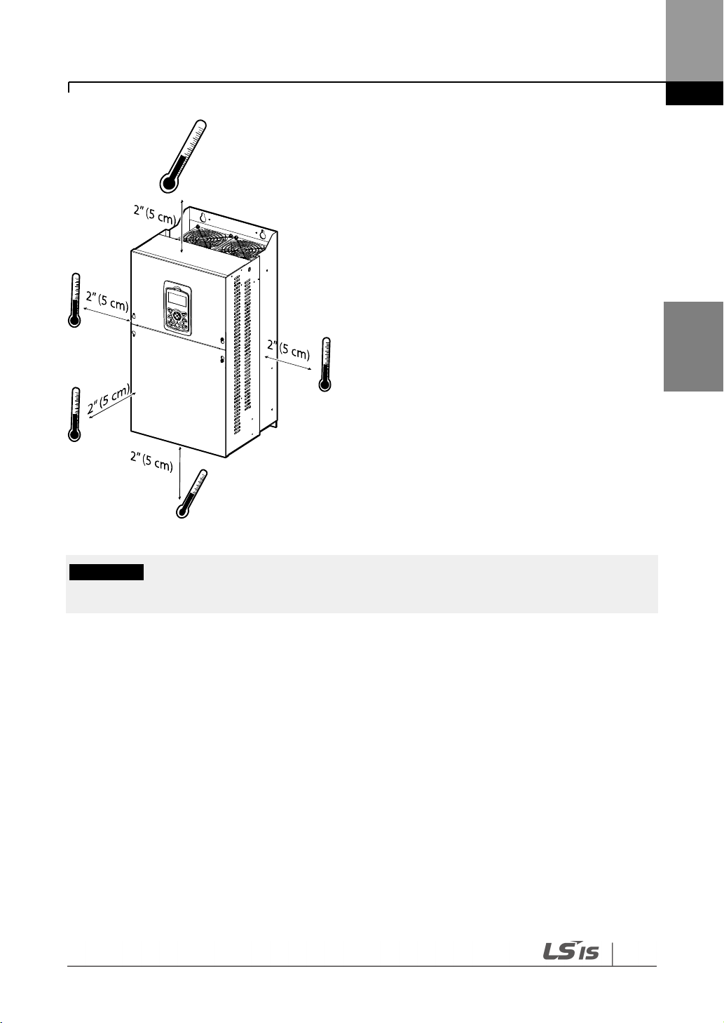
* The ambient temperature is the temperature measured at a point 2” (5 cm) from the surface of the
inverter. No ice or frost should be present.
Installing the Inverter
Installing
the Inverter
17
Do not allow the ambient temperature to exceed the allowable range while operating the inverter.
3.2 Selecting and Preparing a Site for Installation
When selecting an installation location, consider the following requirements:
• The inverter must be installed on a wall that can support the inverter’s weight.
• The location must be free from vibration. Vibrations can adversely affect the operation of
the inverter.
• The inverter can become very hot during operation. Install the inverter on a surface that is
fire resistant or flame retardant with sufficient clearance around the inverter to allow for air
circulation. The illustrations below detail the required installation clearances.

Installing the Inverter
18
Install the inverter on a non-flammable surface, and do not place flammable material near the
inverter. Otherwise, a fire may result.
Note
Model types with capacities of 30 kW or more require a minimum of 8” clearance above and below
the unit.

Installing the Inverter
Installing
the Inverter
19
Note
In order to meet EMC standards, 200 V, 30–75 kW model types and model types with capacities of 90
kW or more should be installed inside a metal cabinet.
• Ensure that the cable conduits do not obstruct the air flow to and from the cooling fan.
• Ensure sufficient air circulation is provided around the inverter when it is installed. If the
inverter is to be installed inside a panel, enclosure, or cabinet rack, carefully consider the
position of the inverter’s cooling fan and vents. The cooling fan must be positioned to
efficiently dissipate the heat generated by the operation of the inverter.

Installing the Inverter
20
• If you are installing multiple inverters of different ratings, provide sufficient clearance to
meet the clearance specifications of the larger inverter. The iS7 inverters rated for up to 30
kW may be installed side by side.

Installing the Inverter
Installing
the Inverter
21
Inverter Capacity
W1
W2
H1
H2
H3
D1 A B
SV0008–0037 iS7 - 2/4
150
(5.90)
127
(5.00)
284
(11.18)
257
(10.11)
18
(0.70)
200
(7.87)
5
(0.19)
5
(0.19)
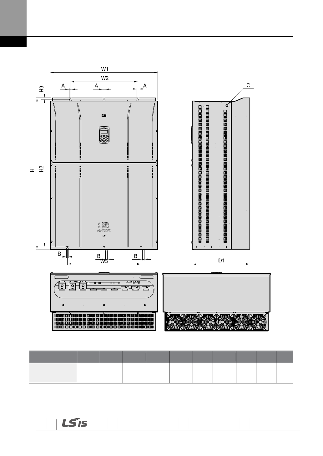
3.3 Exterior and Dimensions (UL Enclosed Type 1, IP21
Type)
SV0008-0037iS7 (200 V/400 V)
Units: mm (inch)

Installing the Inverter
22
Inverter Capacity
W1
W2
H1
H2
H3
D1 A B
SV0055–0075 iS7 - 2/4
200
(7.87)
176
(6.92)
355
(13.97)
327
(12.87)
19
(0.74)
225
(8.85)
5
(0.19)
5
(0.19)
SV0055-0075iS7 (200 V/400 V)
Units: mm (inch)

Installing the Inverter
Installing
the Inverter
23
Inverter Capacity
W1
W2
H1
H2
H3
D1 A B
SV0110–0150 iS7- 2/4
250
(9.84)
214.6
(8.44)
385
(15.15)
355
(13.97)
23.6
(0.92)
284
(11.18)
6.5
(0.25)
6.5
(0.25)
SV0110-0150iS7 (200 V/400 V)
Units: mm (inch)

Installing the Inverter
24
Inverter Capacity
W1
W2
H1
H2
H3
D1 A B
SV0185–0220iS7- 2/4
280
(11.02)
243.5
(9.58)
461.6
(18.17)
445
(17.51)
10.1
(0.39)
298
(11.73)
6.5
(0.25)
6.5
(0.25)
SV0185-0220iS7 (200 V/400 V)
Units: mm (inch)

Installing the Inverter
Installing
the Inverter
25
Inverter Capacity
W1
W2
W3
H1
H2
H3
D1 A B
C
SV0300 iS7-2
300
(11.81)
190
(7.48)
190
(7.48)
570
(22.44)
552
(21.73)
10
(0.39)
265.2
(10.44)
10
(0.39)
10
(0.39)
M8
SV0300-iS7 (200 V, IP00 Type)
Units: mm (inch)

Installing the Inverter
26
Inverter Capacity
W1
W2
W3
H1
H2
H3
D1 A B
C
SV0370–0450
iS7-2
370
(14.56)
270
(10.63)
270
(10.63)
630
(24.8)
609
(23.97)
11
(0.43)
281.2
(11.07)
10
(0.39)
10
(0.39)
M10
SV0370-0450iS7 (200 V, IP00 Type)
Units: mm (inch)

Installing the Inverter
Installing
the Inverter
27
Inverter Capacity
W1
W2
H1
H2
H3
D1
D2 A B
C
SV300–450
iS7-4
300.1
(11.81)
242.8
(9.55)
594.1
(23.38)
562
(22.12)
24.1
(0.94)
DCR type
10
(0.39)
10
(0.39)
M8
303.2
(11.93)
161
(6.33)
Non-DCR type
271.2
(10.67)
129
(5.78)
SV0300-0450iS7 (400 V)
Units: mm (inch)

Installing the Inverter
28
Inverter Capacity
W1
W2
W3
H1
H2
H3
D1 A B
C
SV0550–0750
iS7-2
465
(18.3)
381
(15.0)
381
(15.0)
750
(29.52)
723.5
(28.48)
15.5
(0.61)
355.6
(14.0)
11
(0.43)
11
(0.43)
M16
SV0550-0750iS7 (200 V, IP00 Type)
Units: mm (inch)

Installing the Inverter
Installing
the Inverter
29
Inverter
W1
W2
H1
H2
H3
D1
D2 A B
C
SV0550–0750
iS7-4
370.1
(14.57)
312.8
(12.31)
663.5
(26.12)
631.4
(24.85)
24.1
(0.94)
DCR type
10
(0.39)
10
(0.39)
M8
373.3
(14.69)
211.5
(8.32)
Non-DCR type
312.4
(12.29)
150.6
(5.92)
SV0550-0750iS7 (400 V)
Units: mm (inch)

Installing the Inverter
30
Inverter Capacity
W1
W2
W3
H1
H2
H3
D1 A B
C
SV0900–1100
iS7-4
510
(20.07)
381
(15.0)
350
(13.77)
783.5
(30.84)
759
(29.88)
15.5
(0.61)
422.6
(16.63)
11
(0.43)
11
(0.43)
M16
SV0900-1100iS7 (400 V, IP00 Type)
Units: mm (inch)

Installing the Inverter
Installing
the Inverter
31
Inverter Capacity
W1
W2
W3
H1
H2
H3
D1 A B
C
SV1320–1600
iS7-4
510
(20.07)
381
(15.0)
350
(13.77)
861
(33.89)
836.5
(32.93)
15.5
(0.61)
422.6
(16.63)
11
(0.43)
11
(0.43)
M16
SV1320-1600iS7 (400 V, IP00 Type)
Units: mm (inch)

Installing the Inverter
32
Inverter Capacity
W1
W2
W3
H1
H2
H3
D1 A B
C
SV1850/
2200iS7-4
690
(27.16)
581
(22.87)
528
(20.79)
1078
(42.44)
1043.5
(41.08)
25.5
(1.00)
450
(17.72)
14
(0.55)
15
(0.59)
M20
SV1850-2200iS7 (400 V, IP00 Type)
Units: mm (inch)

Installing the Inverter
Installing
the Inverter
33
Inverter Capacity
W1
W2
W3
H1
H2
H3
D1 A B
C
SV2800iS7-4
771
(30.35)
500
(19.69)
500
(19.69)
1138
(44.80)
1110
(43.70)
15
(0.59)
440
(17.32)
13
(0.51)
13
(0.51)
M16
SV2800iS7 (400 V, IP00 Type)
Units: mm (inch)
For 280 kW model types, I volts are supplied with the product.
Installing the Inverter
34
Inverter Capacity
W1
W2
W3
H1
H2
H3
D1 A B
C
SV3150/
3750iS7-4
922
(36.30)
580
(22.83)
580
(22.83)
1302.5
(51.28)
1271.5
(50.06)
15
(0.59)
495
(19.49)
14
(0.55)
14
(0.55)
M16
SV3150-3750iS7 (400 V, IP00 Type)
Units: mm (inch)
For 315-375 kW model types, I volts are supplied with the product.
Installing the Inverter
Installing
the Inverter
35
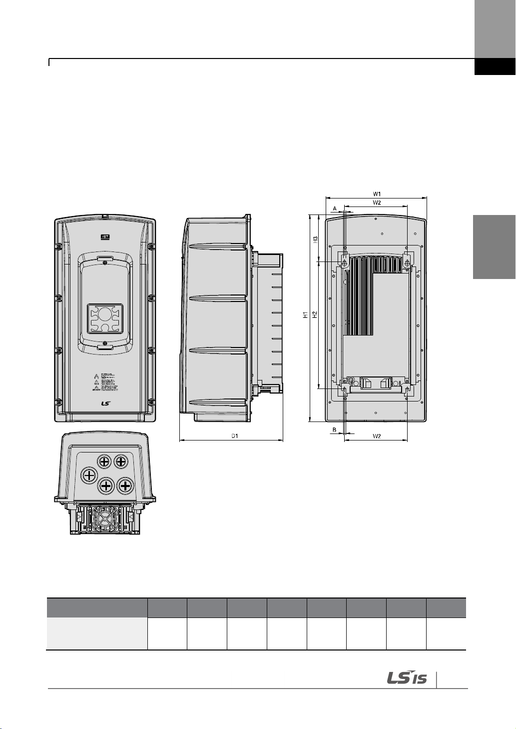
Inverter Capacity
W1
W2
H1
H2
H3
D1 A B
SV0008–0037 iS7-2/4
204.2
(8.03)
127
(5.0)
419
(16.49)
257
(10.11)
95.1
(3.74)
208
(8.18)
5
(0.19)
5
(0.19)
3.4 Exterior and Dimensions (UL Enclosed Type 12,
IP54 Type)
SV0008-0037iS7 (200 V/400 V)
Units: mm (inch)

Installing the Inverter
36
Inverter Capacity
W1
W2
H1
H2
H3
D1 A B
SV0055–0075 iS7-2/4
254
(10.0)
176
(6.92)
460.6
(18.13)
327
(12.87)
88.1
(3.46)
232.3
(9.14)
5
(0.19)
5
(0.19)
SV0055-0075iS7 (200 V/400 V)
Units: mm (inch)

Installing the Inverter
Installing
the Inverter
37
Inverter Capacity
W1
W2
H1
H2
H3
D1 A B
SV0110–0150 iS7-2/4
313.1
(12.32)
214.6
(8.44)
590.8
(23.25)
355
(13.97)
101.7
(4.0)
294.4
(11.59)
6.5
(0.25)
6.5
(0.25)
SV0110-0150iS7 (200 V/400 V)
Units: mm (inch)

Installing the Inverter
38
Inverter Capacity
W1
W2
H1
H2
H3
D1 A B
SV0185–0220 iS7-2/4
343.2
(13.51)
243.5
(9.58)
750.8
(29.55)
445
(17.51)
91.6
(3.60)
315.5
(12.42)
6.5
(0.25)
6.5
(0.25)
SV0185-0220iS7 (200 V/400 V)
Units: mm (inch)

Installing the Inverter
Installing
the Inverter
39
Inverter
Capacity
W[mm]
H[mm]
D[mm]
Weight[Kg]
w/ built-in
EMC and DCR
Weight[Kg]
w/ built-in
EMC
Weight[Kg]
w/ built-in
DCR
Weight[Kg]
non-DCR
types
SV0008iS7-2/4
150
284
200
5.5
4.5
5.0
4.5
SV0015iS7-2/4
150
284
200
5.5
4.5
5.0
4.5
SV0022iS7-2/4
150
284
200
5.5
4.5
5.0
4.5
SV0037iS7-2/4
150
284
200
5.5
4.5
5.0
4.5
SV0055iS7-2/4
200
355
225
10
8.4
9.3
7.7
SV0075iS7-2/4
200
355
225
10
8.4
9.3
7.7
SV0110iS7-2/4
250
385
284
20
17.2
16.8
14
SV0150iS7-2/4
250
385
284
20
17.2
16.8
14
SV0185iS7-2
280
461.6
298
30
27
25.9
22.9
SV0220iS7-2
280
461.6
298
30
25.8
25.9
22.9
SV0185iS7-4
280
461.6
298
27.4
23.5
23.3
19.7
SV0220iS7-4
280
461.6
298
27.4
23.5
23.5
20.1
SV0300iS7-2
300
570
265.2
- - -
29.5
SV0370iS7-2
370
630
281.2
- - -
44
SV0450iS7-2
370
630
281.2
- - -
44
SV0550iS7-2
465
750
355.6
- - -
72.5
SV0750iS7-2
465
750
355.6
- - -
72.5
Note
• The weight specified in the table indicates the total weight of the product without packaging,
which includes the built-in parts, such as the EMC filter and DCR.
• The built-in EMC filter and DCR are not available for 30–75 kW (200 V) products.
3.5 Frame Dimensions and Weight (UL Enclosed Type
1, IP 21 Type)

Installing the Inverter
40
Inverter
Capacity
W[mm]
H[mm]
D[mm]
Weight[Kg]
w/ built-in
EMC and DCR
Weight[Kg]
w/ built-in
EMC
Weight[Kg]
w/ built-in
DCR
Weight[Kg]
non-DCR
types
SV0300iS7-4
300
594
300.4
- - 41
28
SV0370iS7-4
300
594
300.4
- - 41
28
SV0450iS7-4
300
594
300.4
- - 41
28
SV0550iS7-4
370
663.4
371 - -
63
45
SV0750iS7-4
370
663.4
371 - -
63
45
SV0900iS7-4
510
784
423 - -
101 - SV1100iS7-4
510
784
423 - -
101 - SV1320iS7-4
510
861
423 - -
114 - SV1600iS7-4
510
861
423 - -
114 - SV1850iS7-4
690
1078
450 - -
200 - SV2200iS7-4
690
1078
450 - -
200 - SV2800iS7-4
771
1138
440 - - - 252
SV3150iS7-4
922
1302.5
495 - - - 352
SV3750iS7-4
922
1302.5
495 - - - 352
Note
• The weight specified in the table indicates the total weight of the product without packaging,
which includes built-in parts, such as the EMC filter and DCR.
• 300-220 kW (400 V) products have built-in DCR only.
• 280-375 kW (400 V) products are provided without a built-in EMC filter and DCR.

Installing the Inverter
Installing
the Inverter
41
Inverter
Capacity
W[mm]
H[mm]
D[mm]
Weight[Kg]
w/ built-in
EMC and DCR
Weight[Kg]
w/ built-in
EMC
Weight[Kg]
w/ built-in
DCR
Weight[Kg]
non-DCR
types
SV0008iS7-2/4
204
419
208
8.2
7.2
7.7
6.7
SV0015iS7-2/4
204
419
208
8.2
7.2
7.7
6.7
SV0022iS7-2/4
204
419
208
8.2
7.2
7.7
6.7
SV0037iS7-2/4
204
419
208
8.2
7.2
7.7
6.7
SV0055iS7-2/4
254
461
232
12.8
10.2
12.1
9.5
SV0075iS7-2/4
254
461
232
12.9
10.3
12.2
9.6
SV0110iS7-2/4
313
591
294
25.6
22.8
22.4
19.6
SV0150iS7-2/4
313
591
294
25.9
23.1
22.7
19.9
SV0185iS7-2
343
751
316
38.3
34.2
34.1
29.9
SV0220iS7-2
34
751
316
38.3
34.2
34.1
29.9
SV0185iS7-4
343
751
316
34.9
31
31
27.1
SV0220iS7-4
343
751
316
34.9
31
31
27.1
Note
• The weight specified in the table indicates the total weight of the product without packaging,
which includes the built-in parts, such as the EMC filter and DCR.
• Only 0.75-22 kW products are available in IP 54 Type specifications.
3.6 Frame Dimensions and Weight (UL Enclosed Type
12, IP54 Type)

Installing the Inverter
42
3.7 Installation Procedures for UL Enclosed Type12
and IP54 Type Products
3.7.1 Disassembling the Keypad Cover and Keypad
1 Loosen the screws that secure the keypad cover and remove the keypad cover.
2 Depress the tab at the top of the keypad and gently lift the keypad from the inverter to
remove it. Be careful not to damage the keypad cable.
Installing the Inverter
Installing
the Inverter
43
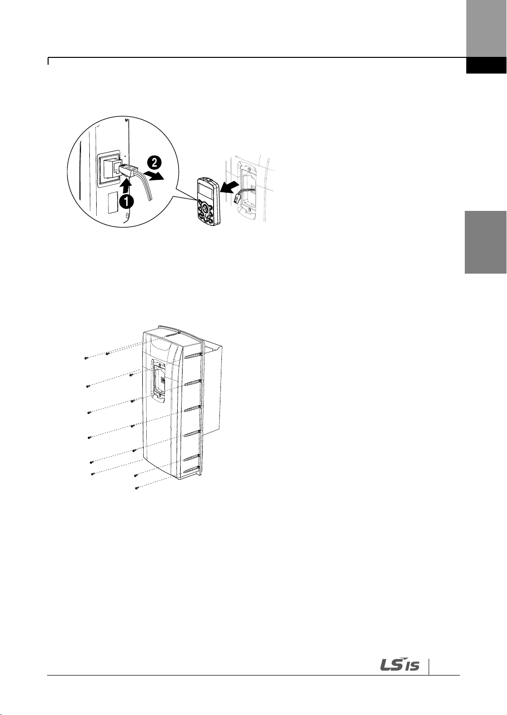
3 Depress the tab on the keypad cable connector and disconnect the cable from the back of
the keypad.
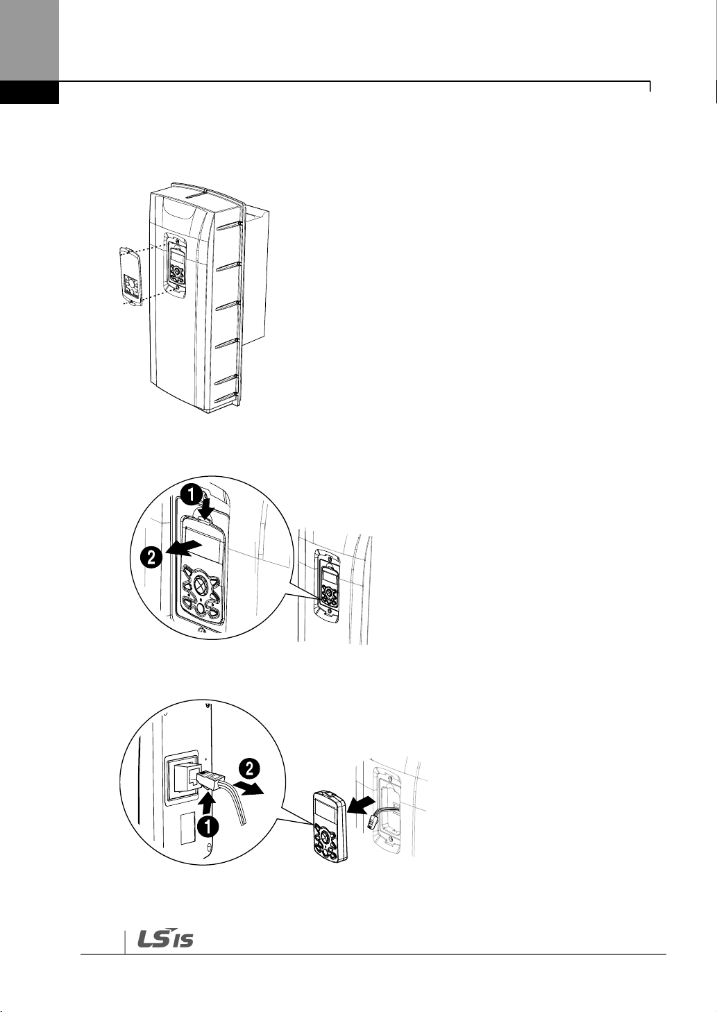
3.7.2 Disassembling the IP54 Front Cover
1 Loosen the screws that secure the front cover to the chassis. There are 9–13 screws on the
cover depending on the model type.

Installing the Inverter
44
2 Remove the cover by lifting it upwards from the bottom.
3.7.3 Mounting the Inverter
1 Remove the 4 rubber feet from the corners.

Installing the Inverter
Installing
the Inverter
45
2 Place the inverter on a flat wall or in a cabinet, and use 4 screws or bolts to securely fix the
inverter to the surface.
3.7.4 Connecting the Power Cables
Connect the power cables to the input (R, S, T) and output (U, V, W) terminals. Then, tighten the
terminal screws.
Refer to 4 Connecting the Cables on page 48 for detailed information.

Installing the Inverter
46
3.7.5 Reassembling the IP54 Front Cover and the Keypad
1 Place the front cover on the chassis and align the screw holes on each side.
2 Insert and tighten the screws. There are 9–13 screws on the cover depending on the model
type.

Installing the Inverter
Installing
the Inverter
47
3 Connect the signal cable to the keypad, align the lower part of the keypad to the bottom of
the keypad receptacle, and then push the top part of the keypad into the chassis until the
keypad snaps into place.
4 Place the keypad cover on top of the keypad, and secure it using 2 screws.

Connecting the Cables
48
ESD (Electrostatic discharge) from the human body may damage sensitive electronic components on
the PCB. Therefore, be extremely careful not to touch the PCB or the components on the PCB with
bare hands while you work on the I/O PCB.
To prevent damage to the PCB from ESD, touch a metal object with your hands to discharge any
electricity before working on the PCB, or wear an anti-static wrist strap and ground it on a metal
object.
Wait at least 10 minutes before opening the covers and exposing the terminal connections. Before
working on the inverter, test the connections to ensure the DC voltage has been fully discharged.
Personal injury or death by electric shock may result if the DC voltage has not been discharged.
4 Connecting the Cables
Connect cables to the power and signal terminal blocks of the inverter.
4.1 Removing the Front Cover for Cable Connection
4.1.1 IP 21 Type Products
1 Depress the tab at the top of the keypad and gently lift the keypad from the inverter to
remove it. Be careful not to damage the keypad cable.

Connecting the Cables
Connecting
the Cables
49
2 Depress the tab on the keypad cable connector and disconnect the cable from the back of
the keypad.
3 Loosen the screw from the bottom part of the front cover, and then remove the front cover.
Connecting the Cables
50
4.1.2 IP 54 Type Products
1 Loosen the two screws securing the keypad cover, and then remove the keypad cover.
2 Depress the tab at the top of the keypad and gently lift the keypad from the inverter to
remove it. Be careful not to damage the keypad cable.
3 Depress the tab on the keypad cable connector and disconnect the cable from the back of
the keypad.

Connecting the Cables
Connecting
the Cables
51
4 Remove the screws from each side of the front cover, and then remove the front cover.
4.1.3 90–375 kW, 400 V and 30–75 kW, 200 V Products
1 Loosen the two screws on the front cover.
2 Slide the cover downwards and remove it from the inverter.

Connecting the Cables
52
Do not activate the EMC filter if the inverter uses a power source with an asymmetrical grounding
structure, for example a grounded delta connection. Personal injury or death by electric shock may
result if the power source is not grounded properly.
4.2 Activating and Deactivating the Built-in EMC
Filter
Some iS-7 inverter models have built-in EMC filters to reduce conductive and radiational noise
at the inverter input. Refer to 1.1.1 Identifying the Product on page 1 and check your inverter’s
model type and specifications to see if it has a built-in EMC filter.
If your inverter has a built-in EMC filter, refer to the following instructions to activate or
deactivate it.
4.2.1 Up to 7.5 kW Inverters
1 Locate the plastic knockout cap that covers the EMC filter switch (jumper SW1).
2 Remove the knockout cap and locate the jumper switch. The EMC filter will be deactivated
if the two jumper pins are not connected.

Connecting the Cables
Connecting
the Cables
53
3 Connect the two jumper pins using a short circuit connector to activate the EMC filter.
4 To remove the short circuit connector and deactivate the EMC filter, pull the connector
while pressing the latch on the side of the connector. Use pliers or tweezers if you cannot
reach the latch with your fingers.

Connecting the Cables
54
4.2.2 11–22 kW Inverters
1 Locate the EMC filter cable and the ground terminal at the bottom of the inverter.
The EMC filter is deactivated if the EMC filter cable is connected to the insulated stud.
2 Remove the EMC filter cable from the insulated stud and connect it to the ground terminal
An EMC filter prevents electromagnetic interference by reducing radio emissions from the
inverter. Using an EMC filter is not always recommended, as it increases current leakage. If an
inverter uses a power source with an asymmetrical grounding connection, the EMC filter must
be turned off.
Before using the inverter, confirm the power supply’s grounding system. Disable the EMC filter
if the power source has an asymmetrical grounding connection.
<EMC filter is turned OFF>
(metal) to activate the EMC filter.
<EMC filter is turned ON>

Connecting the Cables
Connecting
the Cables
55
Asymmetrical Grounding Connection
One phase of
a delta
connection is
grounded
Intermediate
grounding
point on one
phase of a
delta
connection
The end of a
single phase is
grounded
A 3-phase
connection
without
grounding

Connecting the Cables
56
• Do not connect power to the inverter until installation has been fully completed and the inverter
is ready to be operated. Doing so may result in electric shock.
• Wiring and inspection of wiring must be performed by an authorized engineer.
• Install the inverter before connecting the cables.
• Ensure that no metal debris, such as wire clippings, remain inside the inverter. Metal debris in
the inverter can cause inverter failure.
• Power supply cables must be connected to the R, S, and T terminals. Connecting power cables
to other terminals will damage the inverter.
• Use insulated ring lugs when connecting cables to R/S/T and U/V/W terminals.
• The inverter’s power terminal connections can cause harmonics that may interfere with other
communication devices located near the inverter. To reduce interference, the installation of
noise filters or line filters may be required.
• To avoid circuit interruption or damaging connected equipment, do not install phase-advanced
condensers, surge protection, or electronic noise filters on the output side of the inverter.
• To avoid circuit interruption or damaging connected equipment, do not install magnetic
contactors on the output side of the inverter.
• Make sure that the total cable length does not exceed 495 ft (150 m). For inverters < = 3.7 kW
capacity, ensure that the total cable length does not exceed 165 ft (50 m). Long cable runs can
cause reduced motor torque in low frequency applications due to voltage drop. Long cable runs
also increase a circuit’s susceptibility to stray capacitance and may trigger over-current
protection devices or result in the malfunction of equipment connected to the inverter.
• Route the signal cables away from the power cables. Otherwise, signal errors may occur due to
electric interference.
• Tighten terminal screws to their specified torques. Loose terminal block screws may allow the
cables to disconnect and cause a short circuit or inverter failure. Refer to 4.7 Specifications of the
Power Terminal Block and Exterior Fuse on page 6565 for torque specifications.
• Do not place heavy objects on top of electric cables. Heavy objects may damage the cable and
result in electric shock.
• Use cables with the largest cross-sectional area, appropriate for power terminal wiring, to
ensure that voltage drops do not exceed 2%.
• Use copper cables rated at 600 V, 75℃ for power terminal wiring.
• Use copper cables rated at 300 V, 75℃ for control terminal wiring.
• If you need to rewire the terminals due to wiring-related faults, ensure that the inverter keypad
display is turned off and the charge lamp under the terminal cover is off before working on
wiring connections. The inverter may hold a high-voltage electric charge long after the power
supply has been turned off.
4.3 Precautions for Wiring the Inverter

Connecting the Cables
Connecting
the Cables
57
Install ground connections for the inverter and the motor by following the correct specifications to
ensure safe and accurate operation. Using the inverter and the motor without the specified
grounding connections may result in electric shock.
• Do not use the ground terminal as the signal (control) ground.
• Do not share the ground connection with other machines that consume a large amount of
power, such as a welding machine.
• Connect the ground cable to the nearest earth contact and keep the cable length as short as
possible.
Note
• 200 V products require Class 3 grounding. Resistance to ground must be ≤ 100 Ω.
• 400 V products require Special Class 3 grounding. Resistance to ground must be ≤ 10 Ω.
Inverter Capacity
Grounding wire size ( mm²)
200 V class
400 V class
0.75–3.7kW 4 2.5
5.5–7.5 kW 6 4
11–15 kW
16
10
18.5–22 kW
25
16
30–45 kW
25
16
55–75 kW
35
35
90–110 kW - 60
132–220 kW - 100
280–315 kW - 185
375 kW
-
240
4.4 Ground Connection
Because the inverter is a high-frequency switching device, leakage current may occur during
operation. To avoid the danger of electrocution due to current leakage, the inverter must be
properly grounded. Ground connection must be made to the specified ground terminal on the
inverter. Do not connect ground cables to chassis screws.
The following table lists the minimum ground cable specifications that must be met to properly
ground the inverters.

Connecting the Cables
58
R (L1)
S (L2)
T (L3)
3-phase AC input
P (+)
B
N (-) U V
W
Dynamic brake
resistor
To motor
R (L1)
S (L2)
T (L3)
P (+)
B
N (-) U V
W
R (L1)
S (L2)
T (L3)
P1 (+)
P2 (+)
N (-) U V
W
R (L1)
S (L2)
T (L3)
P2 (+)
N (-) U V
W
4.5 Terminal Wiring Diagram
4.5.1 Up to 7.5 kW Inverters
4.5.2 11–22 kW Inverters
4.5.3 30–75 kW Inverters
4.5.4 90–160 kW Inverters

Connecting the Cables
Connecting
the Cables
59
R (L1)
S (L2)
T (L3)
P2 (+)
N (-) U V
W
R (L1)
S (L2)
T (L3)
P1 (+)
P2 (+)
N (-) U V
W
Note
• Inverters with a rated capacity of 11 kW or more are equipped with linearly arranged terminal
blocks.
• 0.75–22 kW inverters have built-in DC reactors. The installation of an external DC reactor is not
necessary for these inverters.
• The inverter must be properly grounded using the ground terminal.
Note
If the forward command (Fx) is turned on, the motor should rotate counterclockwise when viewed
from the load side of the motor. If the motor rotates in the reverse direction, switch the cables at the
U and V terminals.
Remarque
Si la commande avant (Fx) est activée, le moteur doit tourner dans le sens anti-horaire si on le
regarde côté charge du moteur. Si le moteur tourne dans le sens inverse, inverser les câbles aux
bornes U et V.
4.5.5 185–220 kW Inverters
4.5.6 280–375 kW Inverters

Connecting the Cables
60
Power supply cables must be connected to the R, S, and T terminals. Connecting power cables to
other terminals will damage the inverter.
Note
The motor will rotate in the opposite direction if the U, V, and W terminals are connected in a wrong
phase order.
Terminal Symbol
Terminal Name
Description
R (L1), S (L2), T (L3)
AC power supply input
terminals
AC input terminals
P (+)
(+) DC voltage terminal
(+) DC link voltage terminal
N (-)
(-) DC voltage terminal
(-) DC link voltage terminal.
P (+), B
Dynamic brake resistor
terminals
Dynamic brake resistor terminals
U, V, W
Inverter output terminals
Output terminals to a 3-phase induction
motor
4.6 Connecting Cables to the Power Terminal Block
4.6.1 0.75–22 kW (200 V/400 V)
Cable connection for utilizing the built-in dynamic braking unit
Connect the cables from the dynamic braking unit to the P (+) and B terminals to utilize the
built-in dynamic braking unit.

Connecting the Cables
Connecting
the Cables
61
Terminal Symbol
Terminal Name
Description
R (L1), S (L2), T (L3)
AC power supply input
terminals
AC input terminals
P (+)
(+) DC voltage terminal
(+) DC link voltage terminal
N (-)
(-) DC voltage terminal
(-) DC link voltage terminal.
P (+), B
Dynamic brake resistor
terminals
Dynamic brake resistor terminals
U, V, W
Inverter output terminals
Output terminals to a 3-phase induction
motor
Terminal Symbol
Terminal Name
Description
Cable connection for utilizing the optional dynamic braking unit
Connect the cables from dynamic braking unit to P (+) and N (-) terminals to utilize the optional
dynamic braking unit. Do not connect cables to B terminal.
4.6.2 30–75 kW (200 V/400 V)
Connect the cables from the dynamic braking unit to the P (+) and B terminals to utilize the
built-in dynamic braking unit.
In 30-75 kW 200 V model types, the P1 and P2 terminals are connected with a jumper pin.

Connecting the Cables
62
Terminal Symbol
Terminal Name
Description
R (L1), S (L2), T (L3)
AC power supply input
terminals
AC input terminals
P1 (+)
(+) DC voltage terminal
(+) DC link voltage terminal
P2, N (-)
Dynamic brake resistor
terminal / DC common*
Dynamic brake resistor terminals
N (-)
(-) DC voltage terminal
(-) DC link voltage terminal
U, V, W
Inverter output terminals
Output terminals to a 3-phase induction
motor
Note
External DC reactors cannot be used with 30–75 kW inverters. To use a DC reactor with these
inverters, purchase a 30–75 kW inverter that has a built-in DC reactor.
• When a built-in DCR unit is present, the P1 (+) and P (-) terminals are connected to the reactor’s
input and output terminals respectively.
• If your product does not have a built-in DCR unit, the P2 (+) and N (-) terminals may be used as
the common DC source. Do not use the P1 (+) terminal as the common DC source, as this may
result in product damage.
• Use the P2 (+) and N (-) terminals to connect a dynamic braking resistor to the inverter. Do not
connect the dynamic braking unit to the P1 (+) terminal, as this may result in product damage.
• Contact LSIS Customer Support before configuring the N (-) terminal as the DC common source.
There are a few factors that require special attention for this application.
*Contact LSIS Customer Support before configuring the P2 (+) and N (-) terminals as the DC common
source. There are a few factors that require special attention for this application.
4.6.3 90–160 kW (400 V)
Connect the cables from the dynamic braking unit to the P2 (+) and N (-) terminals to utilize an
external dynamic braking unit.

Connecting the Cables
Connecting
the Cables
63
Terminal Symbol
Terminal Name
Description
R (L1), S (L2), T (L3)
AC power supply input terminals
AC input terminals
N (-)
(-) DC voltage terminal
(-) DC link voltage terminal
P2 (+), N (-)
Dynamic brake resistor terminal
Dynamic brake resistor terminals
U, V, W
Inverter output terminals
Output terminals to a 3-phase
induction motor
4.6.4 185–220 kW (400 V)
Connect the cables from the dynamic braking unit to the P2 (+) and N (-) terminals to utilize an
external dynamic braking unit.

Connecting the Cables
64
Terminal Symbol
Terminal Name
Description
R (L1), S (L2), T (L3)
AC power supply input
terminals
AC input terminals
P1 (+)
(+) DC voltage terminal
(+) DC link voltage terminal
P2/N (-)
Dynamic brake resistor
terminal / DC common*
Dynamic brake resistor terminals
N (-)
(-) DC voltage terminal
(-) DC link voltage terminal
U, V, W
Inverter output terminals
Output terminals to a 3-phase induction
motor
• Apply rated torques to the terminal screws. Loose screws may cause the terminals to short
circuit and malfunction. Tightening the screws too much may damage the terminals and cause
them to short circuit and malfunction.
• Only use copper wires with a 600 V, 75 ℃ rating for the power terminal wiring, and a 300 V,
75 ℃ rating for the control terminal wiring.
• Power supply wiring must be connected to the R, S, and T terminals. Connecting them to the U,
V, W terminals causes internal damage to the inverter. The motor should be connected to the U,
V, and W terminals. Arrangement of the phase sequence is not necessary.
4.6.5 280–375 kW (200 V/400 V)
Connect the cables from the dynamic braking unit to the P2 (+) and N (-) terminals to utilize the
built-in dynamic braking unit.
*Contact LSIS Customer Support before configuring the P2 (+) and N (-) terminals as the DC common
source. There are a few factors that require special attention for this application.
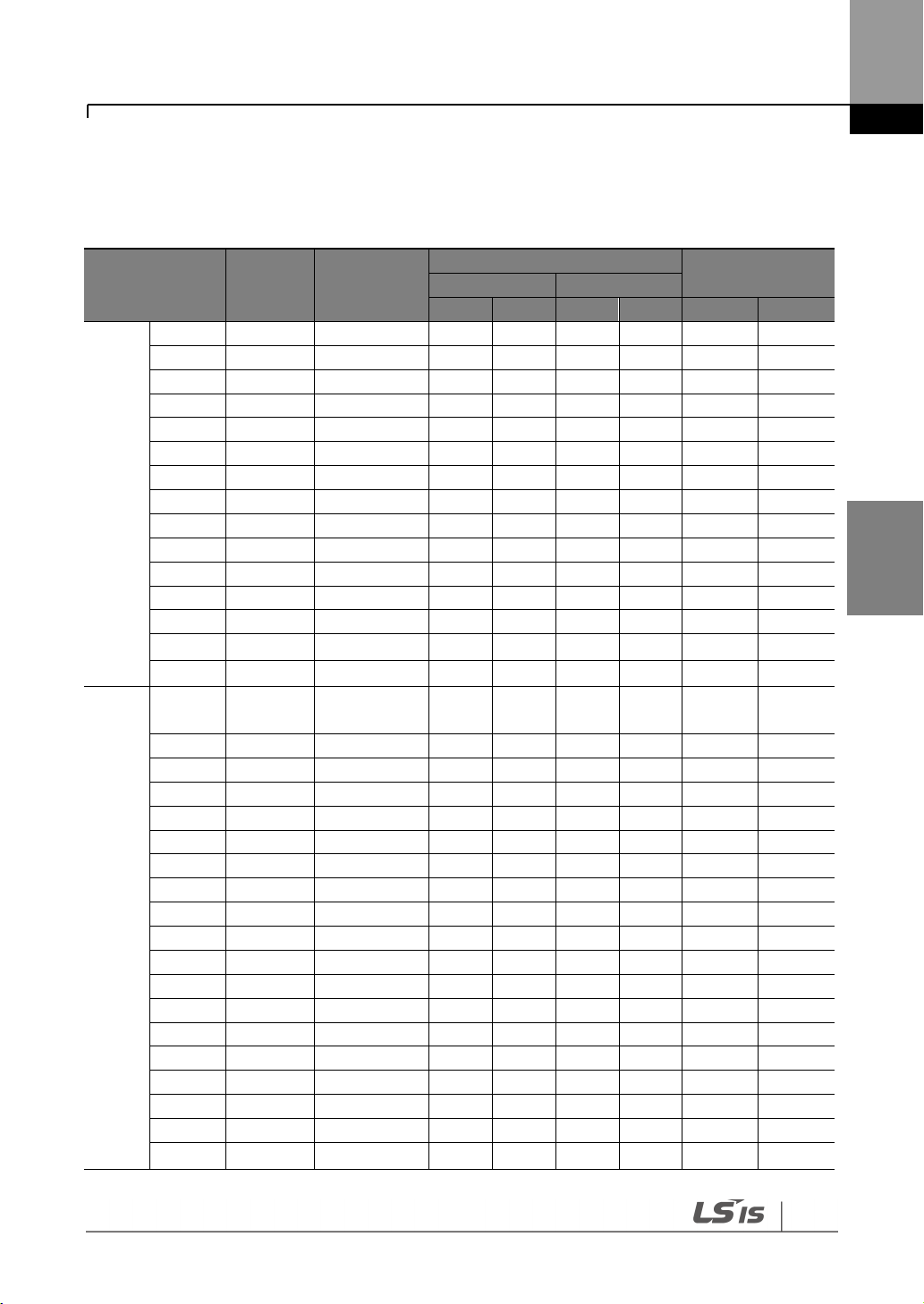
Connecting the Cables
Connecting
the Cables
65
Inverter capacity
Terminal
screw size
Screw torque
1)
(Kgf·cm)
Cable
2)
Exterior fuse
mm²
AWG or kcmil
R,S,T
U,V,W
R,S,T
U,V,W
Current
Voltage
200V
0.75 kW
M4
7.1–12
2.5
2.5
14
14
10 A
500 V
1.5 kW
M4
7.1–12
2.5
2.5
14
14
15 A
500 V
2.2 kW
M4
7.1–12
2.5
2.5
14
14
20 A
500 V
3.7 kW
M4
7.1–12
4 4 12
12
32 A
500 V
5.5 kW
M4
7.1–12
6 6 10
10
50 A
500 V
7.5 kW
M4
7.1–12
10
10 8 8
63 A
500 V
11 kW
M6
30.6–38.2
16
16 6 6
80 A
500 V
15 kW
M6
30.6–38.2
25
25 4 4
100 A
500 V
18.5 kW
M8
61.2–91.8
35
35 2 2
125 A
500 V
22 kW
M8
61.2–91.8
50
50 1 1
160 A
500 V
30 kW
M8
61.2 – 91.8
70
70
1/0
1/0
200 A
500 V
37 kW
M8
61.2 – 91.8
95
95
2/0
2/0
250 A
500 V
45 kW
M8
61.2 – 91.8
95
95
2/0
2/0
350 A
500 V
55 kW
M10
89.7 – 122.0
120
120
3/0
3/0
400 A
500 V
75 kW
M10
89.7 – 122.0
150
150
4/0
4/0
450 A
500 V
400V
0.75–
1.5kW
M4
7.1–12
2.5
2.5
14
14
10 A
500 V
2.2 kW
M4
7.1–12
2.5
2.5
14
14
15 A
500 V
3.7 kW
M4
7.1–12
2.5
2.5
14
14
20 A
500 V
5.5 kW
M4
7.1–12
4
2.5
12
14
32 A
500 V
7.5 kW
M4
7.1–12
4 4 12
12
35 A
500 V
11 kW
M5
24.5–31.8
6 6 10
10
50 A
500 V
15 kW
M5
24.5–31.8
10
10 8 8
63 A
500 V
18.5 kW
M6
30.6–38.2
16
10 6 8
70 A
500 V
22 kW
M6
30.6–38.2
25
16 4 6
100 A
500 V
30 kW
M8
61.2–91.8
25
25 4 4
125 A
500 V
37 kW
M8
61.2–91.8
25
35 4 2
125 A
500 V
45 kW
M8
61.2–91.8
50
50 1 1
160 A
500 V
55 kW
M8
61.2–91.8
70
70
1/0
1/0
200 A
500 V
75 kW
M8
61.2–91.8
95
95
2/0
2/0
250 A
500 V
90 kW
M12
182.4–215.0
100
100
4/0
4/0
350 A
500 V
110 kW
M12
182.4–215.0
100
100
4/0
4/0
400 A
500 V
132 kW
M12
182.4–215.0
150
150
300
300
450 A
500 V
160 kW
M12
182.4–215.0
200
200
400
400
450 A
500 V
185 kW
M12
182.4–215.0
200
200
400
400
620 A
500 V
4.7 Specifications of the Power Terminal Block and
Exterior Fuse

Connecting the Cables
66
Inverter capacity
Terminal
screw size
Screw torque
1)
(Kgf·cm)
Cable
2)
Exterior fuse
mm²
AWG or kcmil
R,S,T
U,V,W
R,S,T
U,V,W
Current
Voltage
220 kW
M12
182.4–215.0
250
250
500
500
800 A
500 V
280 kW
M12
182.4–215.0
325
325
650
650
1000 A
500 V
315 kW
M12
182.4–215.0
2x200
2x200
2x400
2x400
1200 A
500 V
375 kW
M12
182.4–215.0
2x250
2x250
2x500
2x500
1400 A
500 V
Inverter capacity
Up to 3.7 kW
5.5 kW or more
Maximum cable length
< 164 ft (50 m)
< 492 ft (150 m)
Distance
< 165 ft (50 m)
< 330 ft (100 m)
> 330 ft (100 m)
Allowed Carrier Frequency
<15 kHz
<5 kHz
<2.5 kHz
1) Apply rated torques to the terminal screws. Loose screws may cause the terminals to short circuit
and malfunction.
2) Only use copper wires with a 600 V, 75℃ rating for the power terminal wiring.
4.7.1 Cable Length between the Inverter and the Motor
The maximum cable lengths of the inverter and the motor are listed in <Table 1) Maximum
cable length by inverter capacity>.
Make sure that the total cable length does not exceed 495 ft (150 m). For inverters with a
capacity of less than 3.7 kW, ensure that the total cable length does not exceed 165 ft (50 m).
Long cable runs can cause reduced motor torque in low frequency applications due to voltage
drop. Long cable runs also increase a circuit’s susceptibility to stray capacitance and may
trigger over-current protection devices, or result in the malfunction of equipment connected to
the inverter.
<Table 1) Maximum Cable Length by Inverter Capacity>
The following table lists maximum carrier frequencies available for model types with a rated
capacity of 5.5 kW or more.
<Table 2) Maximum Carrier Frequency according to Cable Length>
Depending on the system layout and operating conditions at the installation site, high peak
output voltage may result.

Connecting the Cables
Connecting
the Cables
67
a) If the output peak voltage is too high even when the motor cable length is shorter than the
maximum recommended cable length for the inverter capacity:
- use a motor with a high insulation rating.
- install an output circuit filter (micro surge filter).
- install a dv/dt filter, or a sine wave filter.
b) If the cable length is too long:
- use thicker cables to prevent voltage drop.
[Voltage Drop (V) = [√3 X cable resistance (mΩ/m) X cable length (m) X current (A)] / 1000]
- do not use 3-core cables.
- use a lower carrier frequency.
4.7.2 Protective Measures for the Inverter and the Motor
The inverter output voltage pulse, regardless of the actual output frequency, is identical to the
DC link voltage pulse, which has a very short rising time. When the power is transmitted
through the output cables, the output peak voltage can rise up to twice the total DC link
voltage (2.8 times the main power voltage).
If a switching device (a magnetic contactor or relay) is connected to the output side of the
inverter, high-voltage surges may result whenever a switch is made, regardless of the length of
the motor cable.
Such high-voltage surges can damage the inverter’s output components (such as the current
sensor), motor cables, and the motor itself. To protect the inverter and the motor from such
damage caused by a high-voltage surge, do not install switching devices in the output side of
the inverter. You can install an output reactor, dv/dt filter, or sine wave filter to protect the
inverter and motor from a surge voltage.
An output surge with a high switching frequency and fast rising time causes a motor shaft
current that runs through the motor bearing. It slowly corrodes the surface of the motor
bearing, eventually seizing up the motor.
To decrease the motor shaft current and protect the motor insulation, refer to <Table 1)
Maximum cable length by inverter capacity>. Install a dv/dt filter or sine wave filter if possible,
regardless of the length of the motor cable.

Connecting the Cables
68
Only use Class H or RK5 UL listed input fuses and UL listed breakers. See the table above for the
voltage and current ratings for the fuses and breakers.
Utiliser UNIQUEMENT des fusibles d’entrée homologués de Classe H ou RK5 UL et des disjoncteurs
UL. Se reporter au tableau ci-dessus pour la tension et le courant nominal des fusibless et des
disjoncteurs.
4.8 Control Terminal Wiring for iS7 Inverters Rated
for Up To 22 kW
The iS7 inverter supports both PNP (Source) and NPN (Sink) modes for sequence inputs at the
terminal. Select an appropriate mode to suit your requirements using the PNP/NPN selection
switch above the control terminal block. Refer to the following information for detailed
applications.

Connecting the Cables
Connecting
the Cables
69
4.8.1 NPN Mode (Sink)
Select NPN using the PNP/NPN selection switch. The factory default setting is NPN mode. CM
(24V GND) is the common ground terminal for all terminal inputs.
4.8.2 PNP Mode (Source)
Select PNP using the PNP/NPN selection switch. The factory default setting is NPN mode. CM
(24 V GND) is the common ground terminal for all terminal inputs, and 24 is the 24 V internal
source. If you are using an external 24 V source, select PNP (sink) mode and build a circuit that
connects the external source (-) and the CM terminal.

Connecting the Cables
70
P1
P2
P3
P4
P5
P6
P7
P8
FX
RX
BX
RST
Sp-L
Sp-M
Sp-H
JOG
Note
• The TR (termination resistor) switch is used to terminate the RS485 network connection (120 Ω).
• For analog voltage input, use a potentiometer rated at 0.5W, 1kOhm.
• Refer to 8 Table of Functions on page 154 for the multi-function terminal configurations.
4.8.3 0.75–22 kW (Basic I/O)
Wiring Examples
Default Functions Assigned for the Multi-Function Terminals

Connecting the Cables
Connecting
the Cables
71
4.9 Control Terminal Wiring for iS7 Inverters Rated
for 30 kW or More
30–375 kW (control terminal block)

Connecting the Cables
72
Note
• The TR (termination resistor) switch is used to terminate the RS485 network connection (120 Ω).
• Use a potentiometer rated for 0.5 W, 1 kΩ.
Note
When you use the analog voltage input, the bipolar input range (-10 – +10V), in comparison to the
unipolar input range (0–10V), allows for more accurate input control with smaller increments.
If the analog input is interrupted when setting a frequency reference using the analog voltage (V)
input and no voltage input is received at the terminal, an offset voltage may be applied to keep the
frequency reference at approximately 4–5 Hz.
Input Type
Symbol
Name
Description
Input signal
Terminal
input
P1–P8
Multi-function
input1–8
Configurable for multi-function input terminals.
Refer to 8 Table of Functions on page 154 for the
multi-function terminal configurations.
CM
Common sequence
Common terminal for terminal inputs (5G common
terminal is used for analog frequency inputs only).
Analog
input
VR(+)
Potentiometer
frequency reference
(+)
Used to setup or modify a frequency reference via
the analog voltage or current input.
Maximum output is +12 V, 100 mA.
VR(-)
Potentiometer
frequency reference
(-)
Used to setup or modify a frequency reference via
the analog voltage or current input.
Maximum output is -12 V, 100 mA.
If the analog voltage (V) or current (I) input is used to set the frequency reference, the analog
input is reflected when the input is actually received. For instance, the voltage input 0 V at V1
does not indicate that no input is received at V1, but it means that 0 V input is actually received
at V1.
4.10 Terminal Inputs for Inverter Operation

Connecting the Cables
Connecting
the Cables
73
Input Type
Symbol
Name
Description
V1
Voltage input for
frequency reference
Used to setup or modify a frequency reference via
the analog voltage input terminal.
Unipolar: 0–10 V
Bipolar: -10–10 V
Input resistance 20 kΩ
I1
Current input for
frequency reference
Used to setup or modify a frequency reference via
the current input terminals.
Input current: DC 0–20 mA
Input resistance 249 Ω
5G
Frequency setting
common terminal
Common terminal for analog voltage and current
terminals (CM common terminal is used for
terminal inputs only).
Output Signal
Analog
output
AO1
Multi-function
analog voltage
output terminal
Used to send inverter output information to
external devices.
Output voltage: 0–10 V
Maximum output voltage: 10 V
Maximum output current: 10 mA
AO2
Multi-function
analog current
output terminal
Used to send inverter output information to
external devices.
Output current: 4–20 mA (0–20 mA)
Maximum output current: 20 mA
Terminal
output
Q1
Multi-function
terminal (open
collector)
DC 26 V, below 100 mA
EG
Common terminal
for open collector
Common ground contact for an open collector
(with external power source).
24
External 24 V power
source
Maximum output current: 150 mA
CM
External 24 V
common
Common ground contact for the external 12 V
power source.
A1,
B1,C1
Fault signal output
Sends out alarm signals when the inverter’s safety
features are activated (below AC 250 V 5 A,
DC 30 V 5 A).
Fault condition: A1 and C1 contacts are connected
(B1 and C1 open connection)
Normal operation: B1 and C1 contacts are
connected (A1 and C1 open connection)
A2, C2
Multi-function
relay2 output A
contact
Outputs the signal while running. User defined
multi-function output terminal.
(< AC 250 V, 5 A / < DC 30 V, 5 A)
S+,S-,CM
RS-485 signal line
Used to send or receive RS-485 signals.

Connecting the Cables
74
Terminal Name
Cable size1)
Specifications
mm2
AWG
P1–P8
Multi-function input terminal
0.33–
1.25
16–22
-
CM
Common terminal input
(5G common is used for
analog frequency inputs only).
Common earth for multi-function input
terminal
VR+
Analog frequency setting (+)
power
Output voltage: +12 V
Maximum output voltage: 100 mA
VR-
Analog frequency setting (-)
power
Output voltage: -12 V
Maximum output voltage: 100 mA
V1
Multi-function analog voltage
input terminal
Input voltage: 0–10 V or -10–10 V
I1
Multi-function analog current
input terminal
0–20 mA input
Internal resistance: 249 Ω
AO1
Multi-function analog voltage
output terminal
0.33–
2.0
14–22
Maximum output voltage: 10 V
Maximum output current: 10 mA
AO2
Multi-function analog current
output terminal
Maximum output current: 20 mA
5G
Frequency setting common
terminal (CM common
terminal is used for terminal
inputs only).
Common terminal of analog frequency
setting signal and analog current and
voltage terminals
Q1
Multi-function terminal
(open collector)
DC 26 V, below 100 mA
EG
Ground terminal for external
power
Common terminal for an open collector
external power source
24
External 24 V power supply
0.33–
1.25
16–22
Maximum output current: 150 mA
CM
24 V common
Common terminal for external 24 V power
source
A1
Multi-function relay 1 output A
0.33–
2.0
14–22
Below AC 250 V/5 A, Below DC 30 V/5 A
B1
Multi-function relay 1 output B
Below AC 250 V/5 A, Below DC 30 V/5 A
C1
Multi-function relay 1
common terminal
Below AC 250 V/5 A, Below DC 30 V/5 A
A2
Multi-function relay 2 output A
Below AC 250 V/5 A, Below DC 30 V/5 A
C2
Multi-function relay 2
common terminal
Below AC 250 V/5 A, Below DC 30 V/5 A
S+,S-
RS485 signal input terminal
0.75
18
RS485 signal line
CM
RS485 common terminal
For multi-connections, RS485 power
ground (shield) connection terminal
4.11 Cable Specifications for Control Block Wiring
1) Use shielded, twisted-pair cables.

Connecting the Cables
Connecting
the Cables
75
Power supply system and ground type
Varistors and Y-CAP connection
Effect
Directly grounded system
2-pin connector (on)
Reduced voltage stress and
noise
Non-grounded or impedance
ground system
2-pin connector (off)
Reduced risk of inverter
damage if ground fault
occurs
Note
The 0.75–22 KW (400 V) and 0.75–75 KW (200 V) products do not support this function.
• You can deactivate the built-in surge filter if there is no risk of surge voltage occurring in the
system.
• In order to prevent accidents, remove the jumper switch after the internal voltage of the
inverter is completely discharged.
4.12 Setting the Built-in Surge Filter
The iS7 series inverters have a built-in surge filter between the input phases and the ground
connection to absorb and mitigate surge current. This filter consists of a Y-CAP and multiple
varistors.
However, in a non-grounded power system where specific ground faults occur frequently,
adequate measures are required to avoid inverter damage.
Refer to the following table for details on how to prevent damage to specific power systems.

Connecting the Cables
76
Be careful not to open the front cover with the keypad attached, as this can damage the keypad
cable.
4.13 Activating or Deactivating the Surge Filter
4.13.1 iS7 30–75KW (400 V) Inverters
Contact LSIS Customer Support and ask for assistance to deactivate the built-in surge filter for
the 30–75 KW (400 V) inverters.
4.13.2 iS7 90–375 kW (400V) Inverters
Remove the keypad and the screws from the front cover, and then remove the front cover.
Refer to the figure below and locate the SCR snubber board. On the circuit board, activate or
deactivate the surge filter by connecting the two jumper pins or breaking the connection
between the two pins using a jumper plug. The filter is turned on when the jumper plug is
installed, and it is turned off when the jumper plug is removed.
<Removing the front cover (Ex: 90–160 KW)>

Connecting the Cables
Connecting
the Cables
77
Refer to the following figures to locate the jumper switch on the SCR snubber board and install
or remove the jumper cap to activate or deactivate the built-in surge filter.
SV900-1600iS7 (400 V)
SV1850-2200iS7 (400 V)
SV2800-3750iS7 (400 V)
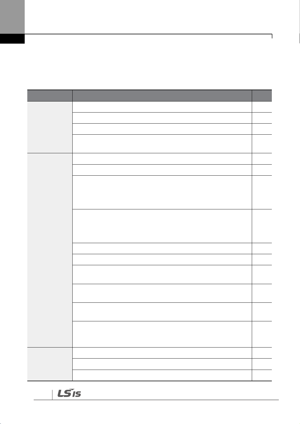
Connecting the Cables
78
Items
Check Point
Result
Installation
Location/Power
I/O Verification
Is the installation location appropriate?
Does the environment meet the inverter’s operating conditions?
Does the power source match the inverter’s rated input?
Is the inverter’s rated output sufficient to supply the equipment?
(Certain circumstances will result in degraded performance.
Power Terminal
Wiring
Is a circuit breaker installed on the input side of the inverter?
Is the circuit breaker correctly rated?
Are the power source cables correctly connected to the R/S/T terminals
of the inverter?
(Caution: connecting the power source to the U/V/W terminals may
damage the inverter.)
Are the motor output cables connected in the correct phase rotation
(U/V/W)?
(Caution: motors will rotate in the reverse direction if three-phase cables
are not wired in the correct phase rotation.)
Are the cables used in the power terminal connections correctly rated?
Is the inverter grounded correctly?
Are the power terminal screws and the ground terminal screws
tightened to their specified torques?
Are the overload protection circuits installed correctly on the motors (if
multiple motors are run using one inverter)?
Is the inverter separated from the power source by a magnetic
contactor (if a braking resistor is in use)?
Are advanced-phase capacitors, surge protection, and electromagnetic
interference filters installed correctly?
(These devices MUST not be installed on the output side of the inverter.)
Control
Terminal Wiring
Are STP (shielded twisted pair) cables used for control terminal wiring?
Is the shielding of the STP wiring properly grounded?
If 3-wire operation is required, are the multi-function input terminals
4.14 Post-Installation Checklist
After completing the installation, check the items in the following table to make sure that the
inverter has been safely and correctly installed.

Connecting the Cables
Connecting
the Cables
79
Items
Check Point
Result
defined prior to the installation of the control wiring connections?
Are the control cables properly wired?
Are the control terminal screws tightened to their specified torques?
Is the total cable length of all control wiring < 328 ft (100 m) for model
types rated at 3.7 kW and below, and 984 ft (300 m) for model types
rated at more than 3.7 kW?
Is the total length of safety wiring < 100 ft (30 m)?
Miscellaneous
Are optional modules connected correctly?
Is there any debris left inside the inverter?
Are any cables contacting adjacent terminals, creating a potential short
circuit risk?
Are the control terminal connections separated from the power
terminal connections?
Have the capacitors been replaced if they have been in use for > 2
years?
Has a fuse been installed for the power source?
Are the connections to the motor separated from other connections?
Note
STP (Shielded Twisted Pair) cables have a highly conductive, shielded screen around twisted-pair
cables. STP cables protect conductors from electromagnetic interference.
4.15 Test Run
When you turn on the iS7 inverter for the first time, it starts in Easy Start mode to help you
configure the basic parameters required for inverter operation.
4.15.1 Entering Easy Start Mode
The inverter starts in Easy Start mode when you turn on the inverter for the first time, or when
the inverter is turned on following a parameter initialization.

Connecting the Cables
80
Note
• Before setting the parameter values for a user application, initialize the parameter settings to
make sure that the default setting is applied to all parameters.
• If you initialized all parameters after an inverter trip occurred, the inverter starts in Easy Start
mode after it is reset, regardless of the pending trip condition.
• Easy Start mode is not available while the inverter is already running.
Sequence
Instruction
Start Easy Set
Select “Yes” to start the inverter in Easy Start mode (select “No” to start
the inverter in Monitor mode).
CNF-01 Language Sel
Select the keypad display language (only English is available at the
moment).
DRV-14 Motor Capacity
Set the motor capacity. (Ex: 0.75 kW, 1.5 kW)
BAS-11 Pole Number
Set the number of poles in the motor.
BAS-15 Rated Volt
Set the rated motor voltage. Set this value to “0 V” if the rated motor
voltage is identical to the input voltage.
BAS-10 60/50 Hz Sel
Set the rated motor frequency.
BAS19 AC Input Volt
Set the inverter input voltage.
DRV-06 Cmd Source
Set the source of the frequency reference. (Ex: KEYPAD, FX/RX-1, FX/RX2, etc.)
DRV-01 Cmd Frequency
Set the frequency reference. (Ex: 50 Hz, 60 Hz, etc.)
Note
While you are in Easy Start mode, you can press the [ESC] key on the keypad to cancel Easy Start
mode and enter Monitor mode.
4.15.2 Setting the Basic Parameters in Easy Start Mode
Refer to the following sequence table to understand the Easy Start sequence and configure the
basic parameters according to the instructions.

Connecting the Cables
Connecting
the Cables
81
Using an inverter, you can easily operate a motor at a high speed. Before operating a motor using
an inverter, ensure that the set speed is within the motor's rated speed.
Ensure that the input power is within the inverter’s rated input voltage range during operation.
4.15.3 Checking the Inverter Operation
Follow the instructions to ensure that the motor operates correctly according to the inverter
settings, and adjust the settings if required.
1 Set DRV-06 (CMD source) to “0 (KEYPAD).”
2 Set DRV-07 (Freq Ref Src) to “0 (Keypad-1).”
3 Set DRV-01 (CMD Frequency) to a temporary speed (Ex: 60 Hz).
4 Press the FWD key on the keypad, and ensure that the motor is rotating in the correct
direction. When the forward command (Fx) is on, the motor should rotate
counterclockwise when viewed from the load side of the motor. If the motor rotates in the
reverse direction, switch the cables at the U and V terminals.

Using the Keypad
82
5 Using the Keypad
5.1 About the Keypad
A keypad is used to set inverter parameters, monitor the inverter’s status, and operate the
inverter.
5.1.1 Dimensions

Using the Keypad
83
Using the
Keypad
Section
Buttons
Key Name
Function Description
KEY
[MODE] key
Used to switch between modes.
[PROG/ENT] key
If this button is pressed once, the parameter can be
edited at the status of the editable parameter code. If
this button is pressed after modification, it will save the
modified data.
[Up] key
Switch between codes, or increase or decrease
parameter values.
[Down] key
[Left] key
Switch between groups or move the cursor during
parameter setup or modification.
[Right] key
[MULTI] key
Used to register jog or user codes.
[ESC] key
If you press this key before pressing the [PROG / ENT]
key, it will revert the parameter value to the previous
value.
If you press this key while editing the codes in any
function group, the keypad will display the first code of
the function group.
If you press this key while moving through the modes,
the keypad will display Monitor mode.
[FWD] key
Used to operate the motor in the forward direction.
[REV] key
Used to operate the motor in the reverse direction.
[STOP/RESET] key
Used to stop the operation and release a fault.
5.1.2 Key Functions
The following table lists the names and functions of the keypad’s operation keys.

Using the Keypad
84
Item
Description
Mode display items
Displays the current mode’s display items. For more details, refer
to 5.3 Navigating Modes on page 90.
5.1.3 Display Items
Monitor Mode
Parameter Mode
5.1.4 Display Item List
The following table lists the items in the display.

Using the Keypad
85
Using the
Keypad
Item
Description
Parameter group items
Displays the current parameter group’s items. For more details,
refer to 5.4 Navigating Modes and Parameters on page 93.
Command source /
frequency reference items
Displays the types of sequences and the number of steps during an
auto sequence operation.
Status display items
Displays the output frequency, output voltage, and current. For
more details, refer to 5.1.3 Display Items on pages 84.
Monitor mode display items
Displays the current operation status. For more details, refer to 5.1.3
Display Items on pages 84.
No
Function
Display
Description
1
Operation
mode
MON
Monitor mode
PAR
Parameter mode
U&M
User-defined and Macro mode
TRP
Trip mode
CNF
Configuration mode
2
Command
source
K
Keypad operation command
O
FieldBus communication option operation command
A
Application option operation command
R
Built-in 485 operation command
T
Terminal block operation command
3
Frequency
reference
K
Keypad frequency command
V
V1 input frequency command
I
I1 input frequency command
P
Pulse input frequency command
U
Frequency command during UP operation
(Up-Down operation)
D
Frequency command during DOWN operation
(Up-Down operation)
S
Frequency command during STOP operation
(Up-Down operation)
O
FBus Option frequency command
X
V2 and I2 frequency commands for sub-terminal block
Monitor display items
The following table lists display icons and their names and functions.

Using the Keypad
86
No
Function
Display
Description
J
Jog frequency command
R
Internal 485 frequency command
1-9 A-F
Multi-step frequency command
4
Multi-function
key settings
JOG key
Used to switch to Keypad JOG mode
Local/Remote
Used to select local or remote operation
User Group
Select key
Used to register parameters as a user group in
Parameter mode or delete parameters in the user
group.
5
Inverter
operating
status
STP
Motor stopped
FWD
Operating in the forward direction
REV
Operating in the reverse direction
DC
DC output
WAN
Warning
STL
Stalling
SPS
Speed Search
OSS
Software over current controlled
OSH
Hardware over current controlled
TUN
Auto tuning
*OSS / OSH may cause overcurrent when the load is too large or when the
acceleration/deceleration time is short. The inverter monitors the output current so that an
overcurrent trip does not occur and also performs overcurrent suppression.
At this time, the output frequency is automatically changed to reduce the output current or
the inverter output is temporarily cut off to prevent overcurrent.

Using the Keypad
87
Using the
Keypad
5.2 Menu Items
The SV-iS7 series inverter uses 5 modes to monitor or configure different functions. Each mode
has its own function items suitable for the desired properties. The parameters in Parameter
mode and User & Macro mode are divided into smaller groups of relevant functions.

Using the Keypad
88
Mode
Display
Description
Monitor mode
MON
Displays the inverter’s operation status information. You can
monitor the frequency setting, operating frequency display,
output current, voltage, etc.
Parameter mode
PAR
Used to configure the functions required to operate the inverter.
These functions are divided into 12 groups based on purpose and
complexity.
User & Macro
mode
U&M
Used to define User and Macro groups. These user-definable
groups allow specific functions of the inverter to be grouped and
managed in separate groups.
This mode will not be displayed when navigating through modes if
no User groups or Macro groups have been defined.
Trip mode
TRP
Used to monitor the inverter’s fault trip information, including the
previous fault trip history.
When a fault trip occurs during inverter operation, the operation
frequency, output current, and output voltage of the inverter at
the time of the fault can be monitored.
This mode will not be displayed if the inverter is not at fault and a
fault trip history does not exist.
Configuration
mode
CNF
Used to configure the inverter features that are not directly
related to the operation of the inverter. The settings you can
configure in Configuration mode include keypad display language
options, monitor mode environment settings, communication
module display settings, and parameter duplication and
initialization.
Mode
Display
Description
Drive group
DRV
Includes frequency/acceleration/deceleration time setting,
operation command selection, etc.
Basic group
BAS
Configures basic operation parameters. These parameters include
motor parameters and multi-step frequency parameters.
Advanced function
group
ADV
Configures acceleration or deceleration, patterns, and frequency
limits.
Control function
group
CON
Configures functions related to sensorless and vector control.
Input terminal
function group
IN
Configures input terminal–related features, including digital multi–
functional inputs and analog inputs.
5.2.1 Parameter Mode

Using the Keypad
89
Using the
Keypad
Mode
Display
Description
Output terminal
function group
OUT
Configures the inverter output terminal block-related features,
including the relay and analog outputs.
Communication
function group
COM
Configures the communication features for the RS-485, if one is
installed.
Application
function group
APP
Configures the features related to PID control and auto sequence
operation.
Auto Sequence run
group
AUT
Configures the necessary features for auto sequence operation.
This group will be displayed if the auto sequence operation in the
APP group is selected.
Application option
group
APO
Configures the encoder and PLC option module-related features if
they are installed.
Protection group
PRT
Configures motor and inverter protection features.
Motor 2 function
group
(Motor 2)
M2
Configures the secondary motor-related features. This group will
be displayed when Motor #2 is selected from the multi-function
input terminal functions.
Group
Display
Description
User group
USR
Used to group frequently accessed function parameters. User
parameter groups can be configured using the multi-function key
on the keypad.
Macro group
MCx
This provides different factory preset groups of functions based on
the type of load. Group MC1, MC2, or MC3 will be displayed when
the user selects the desired load type. Macro groups can be
selected in CNF mode.
5.2.2 User & Macro Mode
 Loading...