


This User's Manual is aimed at……
This User's Manual is aimed at……
Option Module Guide
Describing specification, installation, operation, function, and
maintenance of SV-iS7 series inverter provided for the users
who are familiar with and having basic experience in the inverter.
Be sure to understand function, performance, installation, and
operation of the product by reading through this User's Manual
completely prior to your use of SV-iS7 series inverter that you
have purchased. In addition, you are required to have this User's Manual properly delivered to the end-user and maintenance manager.
The following Option Module Guides will be provided when you
purchase the applicable Option Module. In addition, if you access
our homepage http://www.lsis.biz/ [Support & Service] - [Download Center], you can download it in PDF file.
IS7 PLC Card Option Module Guide
IS7 Encoder Card Option Module Guide
IS7 Profibus-DP Card Option Module Guide
IS7 Modbus-TCP Card Option Module Guide
IS7 LonWorks Card Option Module Guide
IS7 DeviceNet Card Option Module Guide
IS7 I/O Extension Card Option Module Guide
IS7 Built-in RS-485 & Modbus-RTU Option Module Guide
IS7 CANopen Card Option Module Guide
IS7 Ethernet Card Option Module Guide
IS7 CC-Link Card Option Module Guide

Safety Instructions
Remark
WARNING
T o prevent injury and property damage, follow these instructions.
Incorrect operation due to ignoring instructions will cause harm or
damage.
The seriousness of which is indicated by the following symbols.
Symbol Meaning
Even if the instructions are indicated as ‘Caution’, it can cause a serious
result according to the kind of operation and the environment.
The meaning of each symbol in this manual and on your equipment
is as follows.
Symbol Meaning
After reading this manual, keep it in the place that the user always
can contact easily.
This manual should be given to the person who actually uses the
products and is responsible for their maintenance.
Do not remove the cover while power is applied or the unit is in
operation.
Otherwise, electric shock could occur.
Do not run the inverter with the front cover removed.
Otherwise, you may get an electric shock due to high voltage terminals or
charged capacitor exposure.
This symbol indicates the possibility of death or
Warning
serious injury.
This symbol indicates the possibility of injury or
Caution
damage to property.
This is the safety alert symbol.
Read and follow instructions carefully to avoid
dangerous situation.
This symbol alerts the user to the presence of
“dangerous voltage” inside the product that might
cause harm or electric shock.
Safety Instructions
i

Safety Instructions
WARNING
CAUTION
Do not remove the cover except for periodic inspections or wiring,
even if the input power is not applied.
Otherwise, you may access the charged circuits and get an electric shock.
Wiring and periodic inspections should be performed at least 10
minutes after disconnecting the input power and after checking the
DC link voltage is discharged with a meter (below DC 30V).
Otherwise, you may get an electric shock.
Operate the switches with dry hands.
Otherwise, you may get an electric shock.
Do not use the cable when its insulating tube is damaged.
Otherwise, you may get an electric shock.
Do not subject the cables to scratches, excessive stress, heavy
loads or pinching.
Otherwise, you may get an electric shock.
Install the inverter on a non-flammable surface. Do not place
flammable material nearby.
Otherwise, fire could occur.
Disconnect immediately the input power if the inverter gets
damaged.
Otherwise, it could result in a secondary accident and fire.
After the input power is applied or removed, the inverter will remain
hot for a couple of minutes.
Otherwise, you may get bodily injuries such as skin-burn or damage.
Do not apply power to a damaged inverter or to an inverter with parts
missing even if the installation is complete.
Otherwise, electric shock could occur.
Do not allow lint, paper, wood chips, dust, met allic chips or other
foreign matter into the drive.
Otherwise, fire or accident could occur.
ii

Safety Instructions
Caution for Use
Transportation and Installation
Be sure to carry inverter in a proper way suitable for its weight, or it may
result in damage to inverter.
Be sure to use heat-treated wooden crate when you adopt wooden
packaging for the product.
Do not pile up inverters above allowable limit.
Be sure to install the inverter as directed in this instruction manual.
Do not turn off the power supply to the damaged inverter.
Do not open the front cover while carrying the inverter.
Do not place the heavy material on the inverter.
The direction of installation should be observed properly as criterions
specified in this manual show.
Make sure that you should not put screw, metal material, water, oil and the
inflammable something else.
Keep in mind that inverter is very vulnerable to drop from the mid air and
strong shock.
Don't let the inverter exposed to rain, snow, fog, dust, etc.
Do not cover, nor block, the ventilating system having cooling fan. It may
cause the inverter overheated.
Be sure to check the power is off when installing the inverter.
To prevent the risk of fire or electric shock, keep the connected wire in a
sound condition. Use the wire that meets the standard in a recommended
length.
Be sure to ground the inverter. (Under 10 ȳ to 200V class, Under 100Gȳ to
400V class)
iii

Safety Instructions
Wiring
Warning
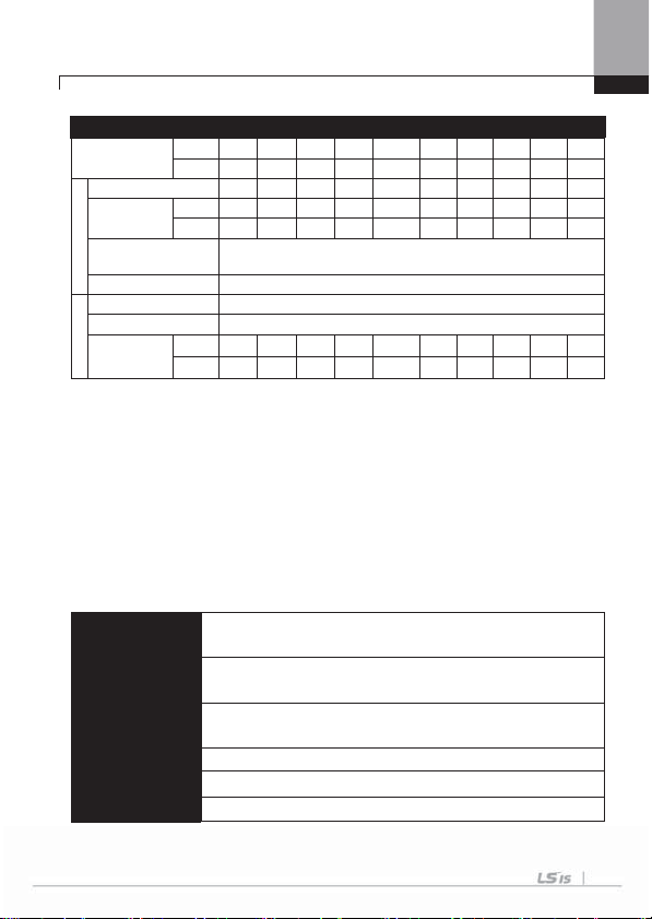
Be certain to use the inverter under the following conditions.
Environment Description
Ambient
Temperature
Ambient Humidity Below 90% RH (Dewdrop should not be formed)
Storage
Temperature
Ambient
Condition
Altitude/Vibration Below 1000m above sea level, Below 5.9m/sec² (=0.6g)
Ambient Air
Pressure
- 10 ~ 40 ϸ (Non-frozen)
(Less than 80% load is recommended at 50ϸ.)
-20 ~ 65ϸ
Free of corrosive gas, inflammable gas, oil sludge and
dust, etc
70 ~ 106 kPa
Caution
A professional installer should have done the wiring and checking.
Do wiring after installing the inverter body.
Do not connect phase-leading capacitors, surge filter, radio noise filter to the
output of inverter.
Output terminals (terminals named U, V, W respectively) should be
connected in a proper phase sequence.
Make sure that there is not any short circuit terminal, wrong wiring. It may
cause spurious operation or failure.
Refrain from using a cable other than the cable shielded when you connect
control circuit wiring.
Adopt the shielded wire only when wiring the control circuit. It may cause the
failure of inverter in its operation. Use the twisted pair shield wire for the
ground terminal of the inverter.
To prevent an electric shock, be sure to check if MCCB and MC are
switched OFF before wiring
Otherwise, it may cause an electric shock.
iv

Safety Instructions
Adjustment before starting trial operation
How to Use
Do not supply the excessive range of voltage displayed in the user manual to
the each terminal. It may cause damage to the inverter.
Current hunting can be occurred in the low speed territory during testing. It
occurs where the capacity is above 110kW with no-load and the axis is not
connected.
The current hunting has a gap according to the motor characteristic. It will be
disappeared when the load is connected and it is not the indication of
abnormal condition.
If the hunting is occurred seriously, please stop the testing and operates with
the load.
Be sure to check relevant parameters for the application before starting trial
operation.
Be sure not to approach the machine when retry function is selected. The
machine may start working suddenly.
Stop key on the keypad should be set to be in use. For safety, additional
emergency stop circuit should be required.
Inverter restarts if alarm condition is cleared while FX/RX signal is on.
Therefore, be sure to operate the alarm reset switch after checking if FX / RX
signal is off.
Never modify the inverter for inappropriate use.
When a magnetic contactor is installed on the power source, do not
frequently start or stop using this magnetic contactor. It may cause the failure
of inverter.
Noise filter should be used for the minimization of troubles by electro-
magnetic noise. Electronic equipments close to the inverter should be
protected against the damage caused by troubles.
Be sure to install the AC reactor at the input of inverter in case of input
voltage unbalance. Otherwise, generator or phase-leading capacitors may
be destroyed by the harmonic current from inverter.
If 400V class motor is used with the inverter, insulation-enforced motor
should be used or countermeasures against the suppression of micro-surge
voltage generated by the inverter should be carried out.
Otherwise, micro-surge voltage is generated across input terminal for the
motor and this voltage lowers allowable insulation break-down voltage and
then, may cause the destruction of the motor.
v

Safety Instructions
Countermeasure against malfunction troubles
Maintenance, inspection and parts replacement
Disposal
Be sure to set the parameters once more, in case of initialization of
parameters, all values of parameters is set to values of factory setting.
High speed operation can be set easily, therefore be sure to check the
performance of motor or machine before changing parameter value.
DC braking function cannot produce a zero-servo torque. If required,
additional equipment should be installed.
When inverter trip or emergency stop (BX) occurs without keypad connected,
LED on the control board will blink by the interval of 0.5 sec. But LED will
blink by 1 sec when keypad is connected. This function displays which trip
will be occurred according to the connection of keypad.
Do not change wiring, nor disconnect connector or option card during the
operation of inverter.
Do not disconnect the motor wiring while the voltage of inverter is output.
Mishandling may cause damage to the inverter.
Be sure to handle the inverter and option care in the order recommended in
the Electro Static Discharge (ESD) Countermeasure. Mishandling may lead
to damage to the circuit on the PCB caused by ESD.
If inverter is damaged and then gets into uncontrollable situation, the
machine may lead to the dangerous situation, therefore to avoid this situation,
be sure to install the additional equipments such as brake.
Do not perform the megger (insulation resistance check) test on the control
board.
Please refer to intervals for parts replacement on Chapter 8.
Handle the inverter as an industrial waste when disposing of it.
Our inverter contains the raw material of value that can be recycled from the
aspect of energy and resource preservation. All the package materials and
metal parts are recyclable. Plastics are also recyclable, but may be burnt
under the controllable environment depending on the local regulation.
vi

Safety Instructions
General Instruction
Cleaning
Storage
Caution
The drawing in this user manual is represented the details of the inner
inverter, so, the drawing is described without cover part and circuit breaker .
But, cover and circuit breaker should be mounted before the operation
following to the instruction of user manual.
Turn off the power of inverter when the inverter is not used.
Be sure to operate the inverter under a clean condition.
When cleaning the inverter, be sure to check the inverter is off. St art cleaning
it with all the plugs connected with the inverter socket removed.
Never clean the inverter using wet cloth or water. Wipe the stained area softly
using the cloth completely wet with a neutral detergent or ethanol.
Never use the solution such as acetone, benzene, toluene, alcohol, etc.
They may cause the coating on the surface of the inverter to peel off. In
addition, do not clean LCD display, etc. using detergent or alcohol.
Be sure to keep the inverter under the following conditions if you
don't use it for a long period of time.
Make sure that you satisfy the recommended storage environment. (See
page v.)
If the storage period exceeds 3 months, be sure to keep it at the ambient
temperature of -10 ~ +30ȋC to preventϩDeterioration by TemperatureϪof
electrolytic condenser.
Be sure to keep it in a proper package to prevent moisture, etc. Put the
desiccant (Silica Gel), etc., in the package so that the relative humidity in the
package can be maintained at 70% or less.
When it is exposed to moisture or dust (mounted on theϩSystemϪ or
ϩControl PanelϪ, etc. installed at the construction site), remove it and then
keep it under the environmental condition specified in the page v.
If the inverter has been left long with electric current not charged, the
nature of electrolytic condenser can be deteriorated. So be sure to
have it plugged in for 30 ~ 60 minutes once a year. Do not perform
wiring and operation of the output side (secondary side).
vii

Safety Instructions
Introduction to the Manual
z This manual describes the specifications, installation, operation,
functions and maintenance of SV-iS7 series inverter and is for the
users who have basic experience of using an inverter.
z It is recommended you read carefully this manual in order to use
SV-iS7 series inverter properly and safely.
z The manual consists as follows.
Chapter Title Contents
Describes the precautions and basic items
1 Basics
which should be learned before using the
Inverter.
2 Specifications
3 Installation
4 Wiring
How to Use
5
Keypad
The control specifications, ratings and
types of the input and output.
Information on the use environment and
installation method.
Wiring information for the power supply and
signal terminals.
Descriptions on the display and operation
keys on the main body of the Inverter.
Descriptions on the basic functions
6 Basic Functions
including frequency setting and operation
command.
Checking and
7
Troubleshooting
Table of
8
Functions
Descriptions on the failures and anomalies
which may occur during operation.
Brief summarize of functions.
viii

Contents
Chapter 1 Basics
1.1 What Y ou Should Know before Use - - - - - - - - - - - - - - - 1-1
1.1.1 Check of product - - - - - - - - - - - - - - - 1-1
1.1.2 Parts - - - - - - - - - - - - - - - 1-2
1.1.3
Preparation of device and Parts for
operation
- - - - - - - - - - - - - - - 1-2
1.1.4 Installation - - - - - - - - - - - - - - - 1-2
1.1.5 Distribution - - - - - - - - - - - - - - - 1-2
1.2 Names and Uses of Parts - - - - - - - - - - - - - - - 1-3
1.2.1 End product (less than 75 kW) - - - - - - - - - - - - - - - 1-3
1.2.2 When the front cover is removed ( less than
75kW)
- - - - - - - - - - - - - - - 1-3
1.2.3 End product (more than 90kW) - - - - - - - - - - - - - - - 1-4
1.2.4 When the front cover is removed (more than
90kW)
- - - - - - - - - - - - - - - 1-4
Chapter 2 Specifications
2.1 Specifications - - - - - - - - - - - - - - - 2-1
2.1.1 Rated Input and Output :
Input voltage of 200V class (0.75~22kW)
2.1.2 Rated Input and Output :
Input voltage of 200V class (30~75kW)
2.1.3 Rated Input and Output :
Input voltage of 400V class (0.75~22kW)
2.1.4 Rated Input and Output :
Input voltage of 400V class (30~160kW)
2.1.5 Rated Input and Output :
Input voltage of 400V class (185~375kW)
- - - - - - - - - - - - - - - 2-1
- - - - - - - - - - - - - - - 2-1
- - - - - - - - - - - - - - - 2-2
- - - - - - - - - - - - - - - 2-2
- - - - - - - - - - - - - - - 2-3
ix

Contents
2.1.6 Other commons - - - - - - - - - - - - - - - 2-3
Chapter 3 Installation
3.1 Installation - - - - - - - - - - - - - - - 3-1
3.1.1 Cautions before installation - - - - - - - - - - - - - - - 3-2
3.1.2 Exterior and Dimension
(UL Enclosed T ype 1, IP21 T ype)
3.1.3 External dimension
(UL Enclosed Type12, IP54 Type)
3.1.4 Dimension and Weight of frame
(UL Enclosed T ype 1, IP21 T ype)
3.1.5 Dimension and Weight of Frame
(UL Enclosed T ype 12, IP54 T ype)
3.1.6 Installation Guide
(UL Enclosed Type12, IP54 Type)
- - - - - - - - - - - - - - - 3-5
- - - - - - - - - - - - - - - 3-30
- - - - - - - - - - - - - - - 3-34
- - - - - - - - - - - - - - - 3-36
- - - - - - - - - - - - - - - 3-37
Chapter 4 Wiring
4.1 Wiring
4.1.1
4.1.2
How to separate front cover when wiring
How to separate front cover when wiring
(90~375 kW 400V, 30~75kW 200V)
4.1.3 Built-in EMC Filter
4.1.4 Wiring precaution
4.1.5 Grounding
4.1.6
Terminal wiring diagram
(Power terminal block)
4.1.7 Terminals of main circuit
Specifications of power terminal block and
4.1.8
Exterior fuse
- - - - - - - - - - - - - - - 4-1
- - - - - - - - - - - - - - - 4-3
- - - - - - - - - - - - - - - 4-5
- - - - - - - - - - - - - - - 4-6
- - - - - - - - - - - - - - - 4-9
- - - - - - - - - - - - - - - 4-9
- - - - - - - - - - - - - - - 4-10
- - - - - - - - - - - - - - - 4-12
- - - - - - - - - - - - - - - 4-14
x

Contents
Control terminal line diagram
4.1.9
(Basic I/O terminal block below 22kW)
4.1.10 Control terminal line diagram
(Insulated I/O terminal block above 30kW)
4.1.11
Control circuit terminal
4.1.12 Specifications of signal terminal block
distribution
4.2 Operation Checking
4.2.1 Easy start
4.2.2 Easy start operation
4.2.3 Checking for normal working
- - - - - - - - - - - - - - - 4-17
- - - - - - - - - - - - - - - 4-21
- - - - - - - - - - - - - - - 4-23
- - - - - - - - - - - - - - - 4-24
- - - - - - - - - - - - - - - 4-26
- - - - - - - - - - - - - - - 4-26
- - - - - - - - - - - - - - - 4-26
- - - - - - - - - - - - - - - 4-27
Chapter 5 How To Use Keypad
5.1 How T o Use Keypad
5.1.1 Standard KEYP AD appearance and
description (Graphic keypad)
5.1.2 Menu composition
5.1.3 Mode shift
5.1.4 Group shift
5.1.5 Code (Function item) shift
5.1.6 Parameter setting
5.1.7 Operating status monitoring
5.1.8 Failure status monitoring
5.1.9 How to initialize parameter
- - - - - - - - - - - - - - - 5-1
- - - - - - - - - - - - - - - 5-1
- - - - - - - - - - - - - - - 5-6
- - - - - - - - - - - - - - - 5-9
- - - - - - - - - - - - - - - 5-10
- - - - - - - - - - - - - - - 5-11
- - - - - - - - - - - - - - - 5-12
- - - - - - - - - - - - - - - 5-13
- - - - - - - - - - - - - - - 5-15
- - - - - - - - - - - - - - - 5-17
Chapter 6 Basic Functions
6.1 Basic Functions - - - - - - - - - - - - - - - 6-1
6.1.1 How to set frequency - - - - - - - - - - - - - - - 6-1
6.1.2 Analog command frequency fixation - - - - - - - - - - - - - - - 6-10
6.1.3 Changing frequency to revolution - - - - - - - - - - - - - - - 6-11
xi

Contents
6.1.4 Sequential frequency setting - - - - - - - - - - - - - - 6-11
6.1.5 Operating command setting method - - - - - - - - - - - - - - 6-12
6.1.6 Prevention of forward or reverse rotation:
Run Prevent
6.1.7 Run Immediately with power on: Power-on
Run
6.1.8 Setting of accelerating/decelerating time and
pattern
- - - - - - - - - - - - - 6-14
- - - - - - - - - - - - - - - 6-14
- - - - - - - - - - - - - - - 6-15
6.1.9 Motor output voltage adjustment - - - - - - - - - - - - - - - 6-19
Chapter 7 Checking and Troubleshooting
7.1
Checking and troubleshooting - - - - - - - - - - - - - - - 7-1
7.1.1
Protective functions - - - - - - - - - - - - - - - 7-1
7.1.2 Alarm functions - - - - - - - - - - - - - - - 7-4
7.1.3 Troubleshooting - - - - - - - - - - - - - - - 7-6
7.1.4 Replacement of cooling fan - - - - - - - - - - - - - - - 7-9
7.1.5 Daily and regular checkup list - - - - - - - - - - - - - - - 7-1 1
Chapter 8 Table of Functions
8.1 T able of Functions - - - - - - - - - - - - - - - 8-1
8.1.1 Parameter mode – DRV group (ÎDRV) - - - - - - - - - - - - - - - 8-1
8.1.2 Parameter mode – Basic function group
(ÎBAS)
8.1.3 Parameter mode – Extended function group
(PARÎADV)
8.1.4 Parameter mode – Control function group
(ÎCON)
8.1.5 Parameter mode – Input terminal block
function group (ÎIN)
- - - - - - - - - - - - - - - 8-3
- - - - - - - - - - - - - - - 8-6
- - - - - - - - - - - - - - - 8-11
- - - - - - - - - - - - - - - 8-16
xii

Contents
8.1.6 Parameter mode – Output terminal block
function group (ÎOUT)
8.1.7 Parameter mode – Communication function
group (ÎCOM)
8.1.8 Parameter mode – Applied function group
(ÎAPP)
8.1.9 Parameter mode – Auto sequence operation
group (ÎAUT)
8.1.10 Parameter mode – Option card function
group (ÎAPO)
8.1.11 Parameter mode – Protective function group
(ÎPRT)
8.1.12 Parameter mode – 2nd motor function
group (ÎM2)
- - - - - - - - - - - - - - - 8-20
- - - - - - - - - - - - - - - 8-25
- - - - - - - - - - - - - - - 8-28
- - - - - - - - - - - - - - - 8-32
- - - - - - - - - - - - - - - 8-36
- - - - - - - - - - - - - - 8-38
- - - - - - - - - - - - - - - 8-41
8.1.13 Trip mode (TRP Current (or Last-x)) - - - - - - - - - - - - - - - 8-42
8.1.14 Config mode (CNF) - - - - - - - - - - - - - - - 8-42
8.1.15 User/Macro mode – ÎMC1 - - - - - - - - - - - - - - - 8-45
8.1.16 User/Macro mode – Traverse operation
function group (ÎMC2)
- - - - - - - - - - - - - - - 8-46
Chapter 9 Peripheral Devices
9.1 Peripheral Devices - - - - - - - - - - - - - - - 9-1
9.1.1 Composition of peripheral devices - - - - - - - - - - - - - - - 9-2
9.1.2 Specifications of wiring switch, Electronic
contactor and Reactor
9.1.3
Dynamic breaking unit (DBU) and Resistors - - - - - - - - - - - - - - - 9-5
9.1.4
IS7 Remote cable options - - - - - - - - - - - - - - - 9-12
- - - - - - - - - - - - - - - 9-3
Chapter 10 Functional Safety
xiii

Contents
10.1 Functional Safety - - - - - - - - - - - - - - - 10-1
10.1.1 Safety Standard product - - - - - - - - - - - - - - - 10-1
10.1.2 Safety function description and wiring
diagram
- - - - - - - - - - - - - - - 10-1
Chapter 11 Classification Product
11.1 Classification Product - - - - - - - - - - - - - - - 11-1
11.1.1 Classification Standard - - - - - - - - - - - - - - - 11-1
11.1.2 Classification standard qcquisition - - - - - - - - - - - - - - - 11-1
11.1.3 Classification Model SV-iS7 Products - - - - - - - - - - - - - - - 11-1
xiv

Chapter 1 Basics
1.1 What Y ou Should Know before Use
1.1.1 Check of product
T ake the inverter out of the box, check the rating shown on a side of the product body
and whether the inverter type and rated output are exactly what you ordered. Check
also whether the product has been damaged during delivery.
SV 008 iS7 - 2 N O F D
Capacity of Applied
Motor
Series
Name
Input
Keypad UL EMC DCR
Voltage
0008 0.75 [kW]
0015 1.5 [kW]
0022 2.2 [kW]
0037 3.7 [kW]
0055 5.5 [kW]
0075 7.5 [kW]
0110 11 [kW]
0150 15 [kW]
0185 18.5 [kW]
0220 22 [kW]
0300 30 [kW]
0370 37 [kW]
0450 45 [kW]
L S Inverter
2:
3-Phase
200~230[V]
4:
3-Phase
380~480[V]
-
N:
NON
S:
GLCD
(Graphic
Loader)
O:
OPEN
E:
Enclosed
UL
note1)
Type1
P:
Enclosed
UL Type 12
Blank:
NonEMC
F:
EMC
Blank:
Non-DCR
D:
DCR
R
:DB
Resistor
(Inner
Mounted)
0550 55 [kW]
0750 75 [kW]
Wide-Use Inverter
0900 90 [kW]
1100 110 [kW]
1320 132 [kW]
1600 160 [kW]
1850 185 [kW]
2200 220 [kW]
2800 280 [kW]
3150 315 [kW]
3750 375 [kW]
Note1)
Enclosed UL Type 1 has the conduit option addtionally at 0.75 to 75 kW products.
Note2)
DB Resistor of IS7 Product is the option of WEB product. Applicable capacity is from 0.75 to 375 kW of IS7
products.
1-1

Chapter 1 Basics
1.1.2 Parts
If you have any doubt about the product or found the product damaged, call our
company’s branch offices (see the back cover of the manual).
1.1.3 Preparation of device and Parts for operation
Preparation for operation might slightly vary. Prep are parts according to the use.
1.1.4 Installation
Make sure you install the product correctly considering the place, direction or
surroundings in order to prevent decrease in the life and performance of the
inverter.
1.1.5 Distribution
Connect the power supply, electric motor and operating signals (control
signals) to the terminal block. If you fail to connect them correctly, the inverter
and peripheral devices might be damaged.
1-2

1.2 Names and Uses of Parts
p
1.2.1 End product (less than 75 kW)
Chapter 1 Basics
Keypad
Screw to fix the
front
Ground terminal
1.2.2 When the front cover is removed (less than 75 kW)
Keypad
connection
Encoder option
Wiring bracket
Front cover:
Remove it when wiring
Wiring bracket
Cooling FAN
Communication
option
connection
Inverter condition
display BAR
PLC, extension I/O,
communication
tion connection
o
I/O board and terminal
Power terminal
1-3

Chapter 1 Basics
pp
p
play
(
)
1.2.3 End Product (more than 90kW)
Screw to fix
Keypad
upper front
cover (left side)
Screw to fix lower
front cover (left side)
Lower front cover
Power input
1.2.4 When the front cover is removed (more than 90kW)
SCR snubber circuit
Communication option
board connection
Encoder option board
Keypad connection
terminal
I/O board and
terminal
Safety option board
(Selectable function)
Cooling fan
Upper front cover
Screw to fix
u
er front
Screw to fix the
lower front cover
(right side)
Signal input
Ground
FAN SMPS
circuit
Main SMPS
circuit
Inverter condition
LED
dis
PLC, Extension I/O,
Communication
tion Connection
o
Shield plate
Power Busbar
R/S/T , U/V/W, P/N
Remark
Please refer to option board manual for option board information.
1-4

Chapter 2 SpecificationsG
)
ۡ
2.1 Specifications
2.1.1 Rated Input and Output : Input voltage of 200V class (0.75~22kW)
Type : SV xxx iS7 – 2x 0008 0015 0022 0037 0055 0075 0110 0150 0185 0220
1)
Motor
Applied
2
Current[A]
Output Frequency
Rated Output
[HP] 1 2 3 5 7.5 10 15 20 25 30
[kW] 0.75 1.5 2.2 3.7 5.5 7.5 11 15 18.5 22
Rated Capacity
[kVA]
3)
Rated
1.9 3.0 4.5 6.1 9.1 12.2 17.5 22.9 28.2 33.5
CT 5 8 12 16 24 32 46 60 74 88
VT 8 12 16 24 32 46 60 74 88 124
4)
0 ~ 400 [Hz]
(Sensorless-1: 0~300Hz, Sensorless-2,Vector: 0~120Hz)
Output Voltage [V] 5)3-phase 200 ~ 230V
Available Voltage [V] 3-phase 200 ~ 230 VAC (-15%,+10%,)
Input Frequency 50 ~ 60 [Hz] (r5%)
Rated
Rated Input
Current [A]
* Non DCR products are provided warranty service when used in CT (Heavy duty) load
rating only.
2.1.2 Rated Input and Output : Input voltage of 200V classۡ(30~75kW)
CT 4.3 6.9 11.2 14.9 22.1 28.6 44.3 55.9 70.8 85.3
VT 6.8 10.6 14.9 21.3 28.6 41.2 54.7 69.7 82.9 116.1
Type : SV xxx iS7 – 2x 0300 0370 0450 0550 0750 - - - - -
1)
Motor Applied
2)
Rated Capacity
3)
Rated
Current[A]
Output Frequency
Rated Output
Output Voltage [V] 5) 3-phase 200 ~ 230V
[HP] 40 50 60 75 100 - - - - -
[kW] 30 37 45 55 75 - - - - -
[kVA]
46 57 69 84 116 - - - - -
CT 116 146 180 220 288 - - - - -
VT 146 180 220 288 345 - - - - -
4)
0 ~ 400 [Hz]
(Sensorless-1: 0~300Hz, Sensorless-2,Vector:0~120Hz)
Available Voltage [V] 3-phase 200 ~ 230 VAC (-15%~+10%)
Input Frequency 50 ~ 60 [Hz] (r5%)
Rated
Rated Input
Current [A]
* Non DCR products are provided warranty service when used in CT (Heavy duty) load
rating only.
G
CT 121 154 191 233 305 - - - - -
VT 152 190 231 302 362 - - - - -
2-1

Chapter 2 SpecificationsG
)
)
2)
4)
2.1.3 Rated Input and Output : Input voltage of 400V class (0.75~22kW)
Type : SV xxx iS7 – 4x 0008 0015 0022 0037 0055 0075 0110 0150 0185 0220
1)
Motor Applied
2
Rated Capacity
3)
Current[A]
Output Frequency
Rated Output
[HP] 1 2 3 5 7.5 10 15 20 25 30
[kW] 0.75 1.5 2.2 3.7 5.5 7.5 11 15 18.5 22
[kVA]
Rated
1.9 3.0 4.5 6.1 9.1 12.2 18.3 22.9 29.7 34.3
CT 2.5 4 6 8 12 16 24 30 39 45
VT 4 6 8 12 16 24 30 39 45 61
4
0 ~ 400 [Hz]
(Sensorless-1:0~300Hz, Sensorless-2,Vector:0~120Hz)
Output Voltage [V] 5)3-phase 380 ~ 480V
Available Voltage [V] 3-phase 380 ~ 480 VAC (-15%~+10%)
Input Frequency 50 ~ 60 [Hz] (r5%)
Rated
Rated Input
Current [A]
* Non DCR products are provided warranty service when used in CT (Heavy duty) load
rating only.
CT 2.2 3.6 5.5 7.5 11.0 14.4 22.0 26.6 35.6 41.6
VT 3.7 5.7 7.7 11.1 14.7 21.9 26.4 35.5 41.1 55.7
2.1.4 Rated Input and Output : Input voltage of 400V class (30~160kW)
Type : SV xxx iS7 – 4x 0300 0370 0450 0550 0750 0900 1100 1320 1600 -
1)
Motor Applied
Rated Capacity [kVA]
3)
Rated
Current[A]
Output Frequency
Rated Output
Output Voltage [V] 5)3-phase 380 ~ 480V
[HP] 40 50 60 75 100 120 150 180 225 [kW] 30 37 45 55 75 90 110 132 160 -
46 57 69 84 116 139 170 201 248 CT 61 75 91 110 152 183 223 264 325 VT 75 91 110 152 183 223 264 325 370 -
0 ~ 400 [Hz]
(Sensorless-1:0~300Hz, Sensorless-2,Vector:0~120Hz)
Available Voltage [V] 3-phase 380 ~ 480 VAC (-15%, +10%)
Input Frequency 50 ~ 60 [Hz] (r5%)
Rated Input
Current[A]
Rated
CT 55.5 67.9 82.4 102.6 143.4 174.7 213.5 255.6 316.3 VT 67.5 81.7 101.8 143.6 173.4 212.9 254.2 315.3 359.3 -
* Non DCR products are provided warranty service when used in CT(Heavy duty) load
rating only.
G
2-2
Chapter 2 SpecificationsG
2)
4)
2.1.5 Rated Input and Output : Input voltage of 400V class (185~375kW)
Type : SV xxx iS7 – 4x 1850 2200 2800 3150 3750 - - - - -
1)
Motor Applied
Rated Capacity [kVA]
3)
Rated
Current[A]
Output Frequency
Rated Output
Output Voltage [V] 5)3-phase 380 ~ 480V
[HP] 250 300 375 420 500 - - - - [kW] 185 220 280 315 375 - - - - -
286 329 416 467 557 - - - - CT 370 432 547 613 731 - - - - VT 432 547 613 731 877 - - - - -
0 ~ 400 [Hz]
(Sensorless-1:0~300Hz, Sensorless-2,Vector:0~120Hz)
Available Voltage [V] 3-phase 380 ~ 480 VAC (-15%, +10%)
Input Frequency 50 ~ 60 [Hz] (r5%)
Rated
Rated Input
Current[A]
1) Motor Applied indicates the maximum capacity applied to use of a standard 4 pole standard motor.
2) Rated capacity : the input capacity of a 200V class is based on 220V and that of a 400V class is based
on 440V. The current rating is based on CT current.
3) The output of rated current is limited according to setting of the carrier frequency (CON-04).
4) In case of Sensorless-1, you can set the frequency at up to 300Hz by selecting 3 as the control mode
(DRV-09 Control Mode). In case of Sensorless-2, you can set the frequency at up to 120Hz by selecting
4 as the control mode (DRV-09 Control Mode).
5) The maximum output voltage does not go up over the supplied power voltage. You can select the output
voltage as you want below the supplied power voltage.
CT 404 466 605 674 798
VT 463 590 673 796 948
- - - - -
- - - - -
2.1.6 Other commons
1) Control
Control Method
Frequency Setting
Resolving Power
Frequency Degree
V/F Pattern
Overload Capacity
Torque boost
V/F control, V/F PG , slip compensation, sensorless vector-1,
sensorless vector-2, vector control
Digital command : 0.01 Hz
Analog command : 0.06 Hz (maximum frequency : 60Hz)
Digital command operation : 0.01% of the maximum frequency
Analog command operation : 0.1% of the maximum frequency
Linear, double reduction, user V/F
CT current rating :150% for 1 min., VT current rating :1 10% for 1 min.
Manual torque boost, Automatic torque boost
* Non DCR products are provided warranty service when used in CT (Heavy duty) load rating only .
2-3

Chapter 2 SpecificationsG
2) Operation
Operating Method
Frequency Setting
Selectable among keypad/ terminal block/
communication operation
Analog : 0 ~ 10[V], -10 ~ 10[V], 0 ~ 20[mA]
Digital : keypad
PID control, up-down operation, 3-wire operation, DC break,
Frequency limit, Frequency jump, Second function, Slip
Operating Function
compensation, Reverse rotation prevention, Auto restarting,
Inverter By-pass, Auto tunning Flying Start, Energy buffering,
Power breaking, Flux breaking, Leakage current reduction,
MMC, Easy Start
NPN (Sink) / PNP (Source) selectable
Function: forward operation, reverse operation, reset, external
trip, emergency stop, jog operation, sequential frequency-
Multi-function
Terminal
(8 points)
Input
P1 ~ P8
high/medium/low, multi - level acceleration and deceleration –
high/medium/low, D.C. control during stop, selection of a second
motor, frequency increase, frequency decrease, 3-wire
1)
operation, change to general operation during PID operation,
Main inverter body operation during option operation, analog
command frequency fixation, acceleration and deceleration stop
selectable
Multi-function
Open Collector
Ter min al
Multi-function
Relay Terminal
Output
Analog Output
1) The Functions for Multi-function terminal available according to IN-65~72 parameter
setting of IN Group.
G
G
G
Failure output and inverter
operation output
0 ~ 10 Vdc (below 20mA) : selectable from frequency, current,
voltage, direct current voltage
Below DC 26V, 100mA
Below (N.O., N.C.) AC250V 1A,
Below DC 30V 1A
2-4
G

3) Protective Function
y
Over voltage, Low voltage, Over current, Earth current detection,
Inverter overheat, Motor overheating, Output imaging, Overload
Trip
protection, Communication error, Frequency command loss,
Hardware failure, Cooling fan failure, Pre-PID failure, No motor trip,
External break trip, etc.
Alarm
Stall prevention, Overload, Light load, Encoder error, Fan failure,
Keypad command loss, Speed command loss.
Below CT class 15 msec (below VT class 8 msec) : Operation
Instantaneous
Interruption
continues (within rated input voltage, rated output)
2)
Above CT class 15 msec (above VT class 8 msec) : Availble
automatic restarts
2) Operation at the CT (Heavy Duty) current rating
4) Structure and Use Environment
Cooling Method
Forced cooling : 0.75~15kW (200/400V class), 22kW (400V class)
Inhalation cooling : 22~75kW (200V class), 30~375kW (400V class)
- 0.75~22kW(200V), 0.75~75kW(400V): Open type IP 21 (default),
Protection
Structure
UL enclosed type 1 (Option)
- 30~75kW (200V), 90~375kW(400V): Open type IP 00 (default),
UL enclosed type 1 (Option)
- 0.75~22kW-2/4 and etc.: Enclosed IP54 type, UL enclosed type 12
- CT (Heavy Duty) load : - 10 ~ 50 (without ice or frost)
Ambient
Temperature
- VT (Normal Duty) load : - 10~ 40 (without ice or frost)
(It is recommended that you use less than 80% load when you use
VT load at 50.)
- IP54 product: -10~40 (without ice or frost)
Preservation
Temperature
Surrounding
Humidit
Altitude, Vibration
Environment
-20qC ~ 65qC
Below 90% RH of relative humidity (with no dew formation)
Below 1,000m, below 5.9m/sec
There should be no corrosive gas, flammable gas, oil mist or dust.
(Pollution degree 2 Environment)
3) UL Enclosed type 1 with conduit box installed.
Chapter 2 SpecificationsG
3)
3)
2
(0.6G)
2-5

Chapter 2 SpecificationsG
2-6
G

Chapter 3 Installation
3.1 Installation
Be sure to check mechanical and electrical installation environment before you start the
inverter. Read through the checking list below. Be sure to read through the Caution for
Safety on this User's Manual prior to the operation of inverter.
Checking List
Mechanical Installation Checking List
y Be sure to check the surrounding environment is allowed for operation. (Read through
the ‘Caution on Installation’)
y Inverter is a heat-generating device. Be sure to sufficiently secure the surrounding
space to prevent thermal saturation phenomenon.
y Be sure to check air is circulated in a normal condition.
y Be sure to check motor and drive system are ready to start.
Electrical Installation Checking List
y Make sure that the protective grounding is properly done.
y Replace the condenser with new one if it lasted longer than two years.
y Set the input voltage to the nominal input voltage of the inverter.
y Check if the input voltage connected with R, S, T and then fasten them tightly using an
accurate torque wrench.
y Check if input power fuse and circuit breaker are properly installed.
y Install the motor cable away from the other cable.
y Check if the ext. input/output is properly connected.
y Check if the input voltage is properly connected with the output terminal of inverter.
3-1

Chapter 3 Installation
r
3.1.1 Cautions before installation
Be careful so that the plastic parts of the inverter may not be damaged. Do not
move the product holding the cover only. Do not install the product where there i
s vibration, a press or truck. Life of the inverter greatly influenced by the surround
ing temperatures, make sure that the surrounding temperature does not exceed th
e permitted temperature (-10 ~ 50qC).
The life of the inverter is affected by ambient temperature. Place that inverter inst
alled in of ambient temperatures should not exceed the following allowable temper
ature.
When the inverter is installed inside the panel, panel temperature must not excee
d the following allowable temperature. In other word, the ambient temperature insi
de or outside of the panel, regardless of the installation, needs to be measured a
round 5cm of the inverter.
㟝GGGhG{G
jSGGGGGGG
{G
j{OoGkPGaGTGXWG¥G\WG G
}{OuGkPaGTGXW¥G[WG G
OoSG}{OuGkPG G \WSGG G _WLG
GGGGPG
pw\[GwGaGTXWG¥[WG
<Measurement Points of Surrounding T emperature>
Install the inverter on an inflammable surface because its temperature rises high
during operation.
Sufficient space is required to prevent heat saturation because the inverter emits
heat.
Enough space is
required for the
distribution duct not to
block the cooling air.
Cooling ai
Built-in cooling fan
(In case of
inhalation air
cooling type)
over
5cm
B
A: over 10cm
Inverte
B
over
5cm
A: over10cm
3-2
Built-in cooling fan
(In case of forced
air cooling type)
Chapter 3 Installation
Built-i
Remark
Over 50cm, B : over 20cm is necessary when you install an inverter above 30kW.
Caution
Avoid direct rays of light or a warm and humid place.
Install the inverter in a closed panel or clean place free from foreign substances such as
oil mist and fiber dust.
In order to meet the EMC standard, 200V 30~75kW and more than 90kW product should
be installed inside a metal cabinet or panel.
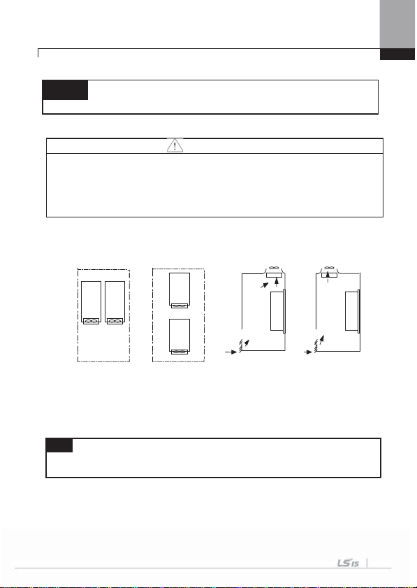
If you install two or more inverters inside the panel, be careful about the location
of the ventilation fan and inverter. See the figure below.
Inverte
Inverter
Inverter
r
Inverter
Ventilation
Ventilation
I
nverter
n coolingfan
(O)
Acceptable
When two or more units are installed
Inverter
Unacceptable
(X)
Acceptable
(O)
Unacceptable
Where the ventilation fan is installed
(X)
Install the inverter upright using screws or bolts so that the inverter does not move.
Note
Arrange the panels in order to the hot air generated by the heating of the inverter should
be released.
3-3
Chapter 3 Installation
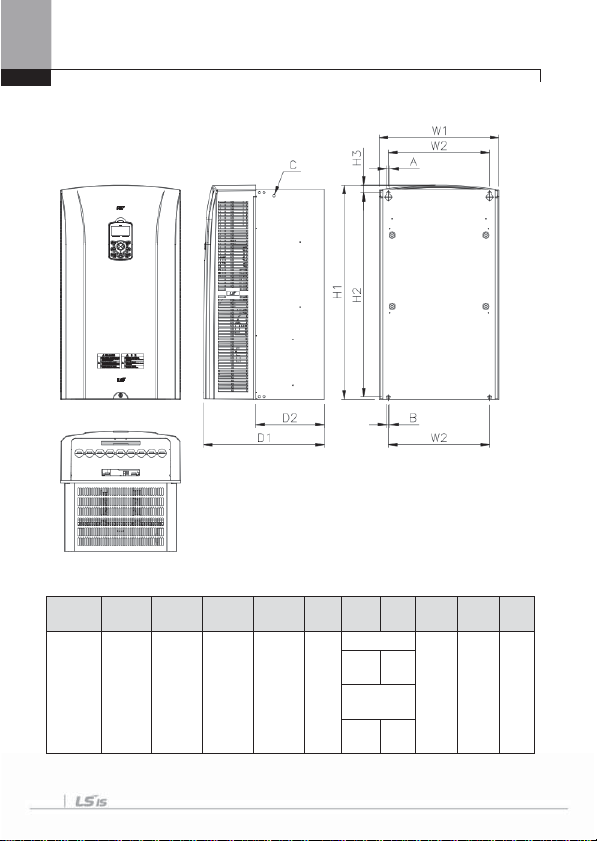
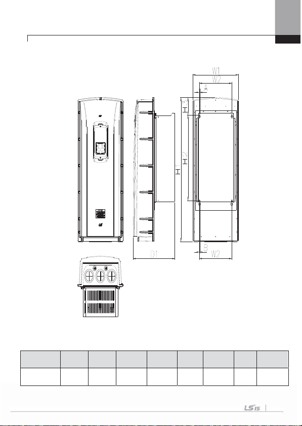
3.1.2 Exterior and Dimension (UL Enclosed T ype 1, IP21 Type)
1) SV0008-0037iS7 (200V/400V)
Inverter
capacity
SV0008~0037
iS7 - 2/4
3-4
mm ( inches )
W1 W2 H1 H2 H3 D1 A B
150(5.90) 127(5.00) 284(11.18) 257(10.11) 18(0.70) 200(7.87) 5(0.19) 5(0.19)
2) SV0055-0075iS7 (200V/400V)
)
Chapter 3 Installation
Inverter
capacity
SV0055~0075
iS7 - 2/4
mm ( inches )
W1 W2 H1 H2 H3 D1 A B
200(7.87) 176(6.92) 355(13.97
327(12.87)19(0.74) 225(8.85) 5(0.19) 5(0.19)
3-5

Chapter 3 Installation
)
3) SV0110-0150iS7 (200V/400V)
Inverter
capacity
SV0110~0150
iS7- 2/4
3-6
mm ( inches )
W1 W2 H1 H2 H3 D1 A B
250(9.84) 214.6(8.44
385(15.15) 355(13.97) 23.6(0.92 284(11.18) 6.5(0.25) 6.5(0.25)

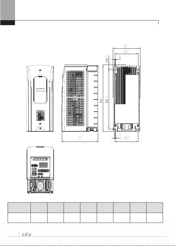
4) SV0185-0220iS7 (200V/400V)
4
Chapter 3 Installation
Inverter
capacity
SV0185~0220
iS7- 2/4
mm ( inches )
W1 W2 H1 H2 H3 D1 A B
280(11.02) 243.5(9.58)
61.6(18.17)445(17.51) 10.1(0.39)298(11.73) 6.5(0.25)6.5(0.25)
3-7

Chapter 3 Installation
5) SV0300-iS7 (200V, IP00 Type)
3-8
Inverter
capacity
SV0300
iS7-2
W1 W2/W3 H1 H2 H3 D1 A B
300
190
570
552
10
265.2
(11.81)
(7.48)
(22.44)
(21.73)
(0.39)
(10.44)
10
(0.39)
mm ( inches )
C
10
M8
(0.39)

6) SV0370-0450iS7 (200V, IP00 Type)
Chapter 3 Installation
Inverter
capacity
SV0370~04
50
iS7-2
mm ( inches )
W1 W2/W3 H1 H2 H3 D1 A B
370
270
630
609
11
281.2
(14.5
6)
(10.63)
(24.8)
(23.97)
(0.43)
(11.07)
10
(0.39)
10
(0.39)
C
M10
3-9

Chapter 3 Installation
7) SV0300-0450iS7 (400V)
mm ( inches )
Inverter
capacityW1 W2 H1 H2 H3 D1 D2 A B C
SV300~
450
iS7-4
3-10
300.1
(11.81)
242.8
(9.55)
594.1
(23.38)
562
(22.12)
DCR Type
303.2
(11.93)
161
(6.33)
24.1
(0.94)
Non-DCR Type
271.2
129
(10.67(
(5.78)
10
(0.39)
M8
10
(0.39)

8) SV0550-0750iS7 (200V, IP00 Type)
Chapter 3 Installation
Inverter
capacity
SV0550~0
750
iS7-2
mm ( inches )
W1 W2/W3 H1 H2 H3 D1 A B
465
381
750
723.5
15.5
355.6
(18.3)
(15.0)
(29.52)
(28.48)
(0.61)
(14.0)
11
(0.43)
11
(0.43)
C
M16
3-11
Chapter 3 Installation
)
)
9) SV0550-0750iS7 (400V)
Inverter
capacity
SV0055~
W1 W2 H1 H2 H3 D1 D2 A B
370.1
(14.57)
312.8
(12.31)
0075
iS7-4
663.5
(26.12)
631.4
(24.85)
24.1
(0.94)
DCR Type
373.3
(14.69
Non-DCR
Type
312.4
(12.29
211.5
(8.32)
150.6
(5.92)
mm ( inches )
10
(0.39)
10
(0.39)
C
M8
3-12

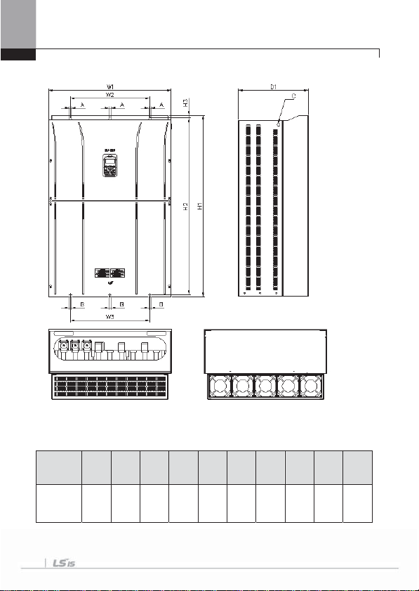
10) SV0900-1100iS7 (400V, IP00 Type)
Chapter 3 Installation
Inverter
capacity
SV0900~
1100
iS7-4
mm ( inches )
W1 W2 W3 H1 H2 H3 D1 A B
510
381
350
783.5
759
15.5
422.6
(20.07)
(15.0)
(13.77)
(30.84)
(29.88)
(0.61)
(16.63)
11
(0.43)
11
(0.43)
C
M16
3-13

Chapter 3 Installation
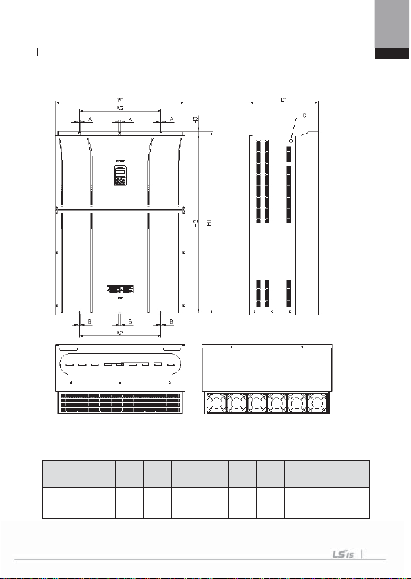
11) SV1320-1600iS7 (400V, IP00 Type)
Inverter
mm ( inches )
capacityW1 W2 W3 H1 H2 H3 D1 A B
SV1320
~1600
iS7-4
510
(20.07)
381
(15.0)
350
(13.77)
861
(33.89)
836
(32.93)
15.5
(0.61)
422.6
(16.63)
11
(0.43)
3-14
11
(0.43)
C
M16

12) SV1850-2200iS7 (400V, IP00 TYPE)
G
G
G
Chapter 3 Installation
Inverter
capacity
z}X_\WVG
YYWWz^T[G
W1GW2GW3GH1GH2GH3GD1GAGB
]`WG
\_XG
\Y_G
XW^_
XW[ZU\
Y\U\G
OY^UX]PG
OYYU_^PG
OYWU^`P
O[YU[[P
O[XUW_P
OXUWWP
[\WG
OX^U^YPG
mm ( inches )
X[G
X\G
OWU\\PG
OWU\`PGtYW
C
3-15
Chapter 3 Installation
G
GOGGPG
G
G
13) SV2800iS7 (400V, IP00 TYPE )
Inverter
capacity
z}Y_WWz^
W1GW2GW3GH1GH2GH3GD1GAGB
G
^^XG
\WWG
T[G
OZWUZ\PG
OX`U]`PG
\WWG
OX`U]`P
O[[U_WP
XXZ_
XXXW
O[ZU^WP
X\G
OWU\`P
[[WG
OX^UZYP
XZG
OWU\XPG
XZG
OWU\XPG
C
G
tX]G
3-16
14) SV3150-3750iS7 (400V, IP00 TYPE )
G
G
~XG ~YG ~ZG oXG oYG oZG kXG hG iG
G
jG
Chapter 3 Installation
Inverter
capacity
SV3150/
3750iS7-4
922
580
580
1302.5
1271.5
15
(36.30)
(22.83)
(22.83)
(51.28)
(50.06)
(0.59)
495
(19.49)
(0.55)
14
mm ( inches )
14
M16
(0.55)
3-17

Chapter 3 Installation
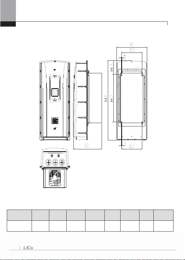
3.1.3 External dimension (UL Enclosed Ty pe12, IP54 Type)
1) SV0008-0037iS7 (200V/400V)
Inverter
capacity
SV0008~0037
iS7-2/49
3-18
mm ( inches )
W1 W2 H1 H2 H3 D1 A B
204.2
127
(8.03)
(5.0)
419
(16.49)
257
(10.11)
95.1
208
(3.74)
(8.18) 5(0.19) 5(0.19)

2) SV0055-0075iS7 (200V/400V)
Chapter 3 Installation
Inverter
capacity
SV0055~0075
iS7- 2/4
mm ( inches )
W1 W2 H1 H2 H3 D1 A B
254
176
(10.0)
(6.92)
460.6
(18.13)
327
(12.87)
88.1
232.3
(3.46)
(9.14) 5(0.19) 5(0.19)
3-19
Chapter 3 Installation
3) SV0110-0150iS7 (200V/400V)
Inverter
capacity
SV0110~0150
iS7-2/4
3-20
mm ( inches )
W1 W2 H1 H2 H3 D1 A B
313.1
214.6
(12.32)
(8.44)
590.8
(23.25)
355
(13.97)
101.7
(4.0)
294.4
(11.59)
6.5
(0.25)
6.5
(0.25)
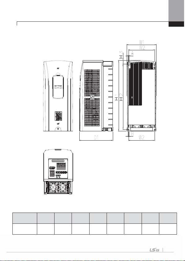
4) SV0185-0220iS7 (200V/400V)
Chapter 3 Installation
Inverter
capacity
SV0185~0220
iS7-2/4
mm ( inches )
W1 W2 H1 H2 H3 D1 A B
343.2
243.5
(13.51)
(9.58)
750.8
(29.55)
445
(17.51)
91.6
(3.60)
315.5
(12.42)
6.5
(0.25)
6.5
(0.25)
3-21

Chapter 3 Installation
3.1.4 Dimension and Weight of frame (UL Enclosed Type 1, IP 21Type)
Inverter
Capacity W[mm] H[mm] D[mm]
SV0008iS7-2/4 150 284 200 5.5 4.5 5.0 4.5
SV0015iS7-2/4 150 284 200 5.5 4.5 5.0 4.5
SV0022iS7-2/4 150 284 200 5.5 4.5 5.0 4.5
SV0037iS7-2/4 150 284 200 5.5 4.5 5.0 4.5
SV0055iS7-2/4 200 355 225 10 8.4 9.3 7.7
SV0075iS7-2/4 200 355 225 10 8.4 9.3 7.7
SV0110iS7-2/4 250 385 284 20 17.2 16.8 14
SV0150iS7-2/4 250 385 284 20 17.2 16.8 14
SV0185iS7-2 280 461.6 298 30 27 25.9 22.9
SV0220iS7-2 280 461.6 298 30 25.8 25.9 22.9
SV0300iS7-2 300 570 265.2
SV0370iS7-2 370 630 281.2
SV0450iS7-2 370 630 281.2
SV0550iS7-2 465 750 355.6
SV0750iS7-2 465 750 355.6
SV0185iS7-4 280 461.6 298 27.4 23.5 23.3 19.7
SV0220iS7-4 280 461.6 298 27.4 23.5 23.5 20.1
SV0300iS7-4 300.1 594.1 300.4 - - 41 28
SV0370iS7-4 300.1 594.1 300.4 - - 41 28
SV0450iS7-4 300.1 594.1 300.4 - - 41 28
SV0550iS7-4 370 663.4 371. - - 63 45
SV0750iS7-4 370 663.4 371. - - 63 45
SV0900iS7-4 510 783.5 422.6 - - 101 -
EMC&DCL
Weight
Only EMC
[Kg]
Product
weight[Kg]
- - 29.5
- - 44
- - 44
- - 72.5
- - 72.5
Only DCL
Product
weight[Kg]
Non EMC
and DCL
Product
weight[Kg]
3-22

Chapter 3 Installation
Inverter
Capacity W[mm] H[mm] D[mm]
SV1100iS7-4 510 783.5 422.6 - - 101 -
SV1320iS7-4 510 861 422.6 - - 114 SV1600iS7-4 510 861 422.6 - - 114 SV1850iS7-4 690 1078 450 - - -200 SV2200iS7-4 690 1078 450 - - -200 SV2800iS7-4 771 1138 440 - - - 252SV3150iS7-4 922 1302.5 495 - - - -352
SV3750iS7-4 922 1302.5 495 - - - -352
Note
Weight[Kg] above indicates the total weight including EMC FIL TER and DCL. (excluding
box packing) 30 through75 kW (200V) products don’t have an option type. 30 through
160kW(400V) products have only DCL option type. 280 through 375kW (400V) products
have not EMC and DCL option.
EMC&DCL
Weight
[Kg]
Only EMC
Product
weight[Kg]
Only DCL
Product
weight[Kg]
Non EMC
and DCL
Product
weight[Kg]
3-23

Chapter 3 Installation
3.1.5 Dimension and Weight of Frame
(UL Enclosed Type 12, IP54 Type)
Inverter
Capacity W[mm] H[mm] D[mm]
SV0008iS7-2/4 204.2 419 208 8.2 7.2 7.7 6.7
SV0015iS7-2/4 204.2 419 208 8.2 7.2 7.7 6.7
SV0022iS7-2/4 204.2 419 208 8.2 7.2 7.7 6.7
SV0037iS7-2/4 204.2 419 208 8.2 7.2 7.7 6.7
SV0055iS7-2/4 254 460.6 232.3 12.8 10.2 12.1 9.5
SV0075iS7-2/4 254 460.6 232.3 12.9 10.3 12.2 9.6
SV0110iS7-2/4 313.1 590.8 294.4 25.6 22.8 22.4 19.6
SV0150iS7-2/4 313.1 590.8 294.4 25.9 23.1 22.7 19.9
SV0185iS7-2 343.1 750.8 315.5 38.3 34.2 34.1 29.9
SV0220iS7-2 343.2 750.8 315.5 38.3 34.2 34.1 29.9
SV0185iS7-4 343.2 750.8 315.5 34.9 31 31 27.1
SV0220iS7-4 343.2 750.8 315.5 34.9 31 31 27.1
Note
Weight[Kg] above indicates total weight. (excluding packing)
0.75~22 kW products have only IP54 type product.
EMC&DCL
Weight[Kg]
Only EMC
Weight[Kg]
Only DCL
Weight[Kg]
Non
EMC&DCL
Weight[Kg]
3-24
Chapter 3 Installation
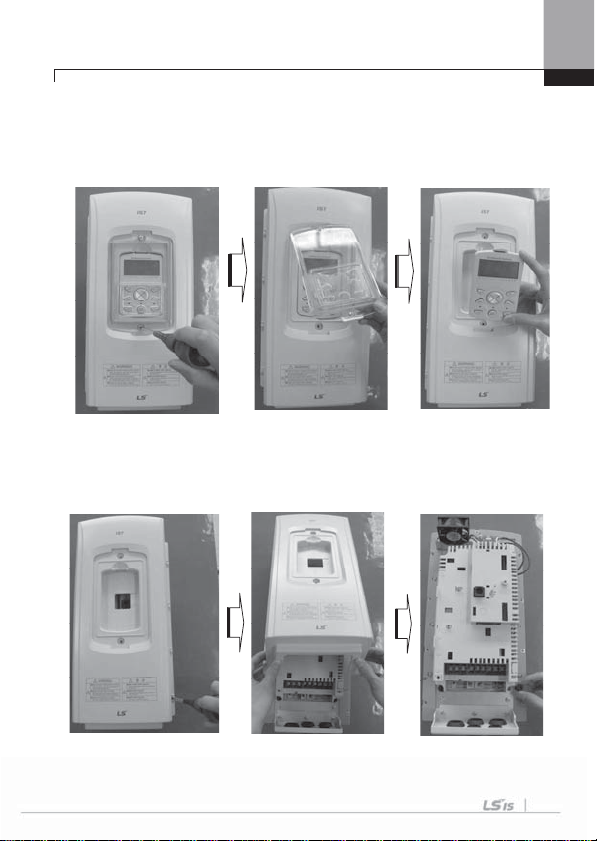
3.1.6 Installation Guide (UL Enclosed Type12, IP54 Ty pe)
1) How to separate IP54 keypad cover and keypad
- Release the upper/lower screw on the transparent keypad cover and then separate
the transparent cover from the inverter.
- Separate the keypad from the inverter.
2) How to separate IP54 front cover
- Loosen the captive screws (nine or thirteen, depending on the size of the frame)
around the edge of the cover.
- Remove the cover.
3-25

Chapter 3 Installation
3) Mounting the inverter
- Remove the four rubber packings on the corner.
- Mount the inverter onto fixing hole on the panel and securely tighten the four screws
or bolts.
- Place the four rubber packings to the each corner.
4) Power cable wiring
- Connects the input/output power cable as followed picture.
- Refer to Chapter 4 Wiring for the detailed wiring.
3-26

Chapter 3 Installation
5 How to attach the IP54 front cover
- Place the front cover matching with plate hole.
- Securely tighten the screw at the corner of front cover.
- Connect the cable to the keypad and then place the front cover on the inverter.
- Place the transparent keypad cover on the keypad and tighten the upper/lower screw .
3-27
Chapter 3 Installation
3-28

Chapter 4 Wiring
4.1 Wiring
Do the wiring of inverter and then check the wiring of main circuit and control circuit
before starting it. Read through the checking list as below.
Checking List
Inverter, Peripherals, Option card
Is the inverter supplied in the form as ordered?
y
Are the type and numbers of peripherals (Resistance, DC reactor, Noise
filter, etc.) supplied as ordered?
y
Is the type of option supplied as supplied?
Place of the inverter to be installed and how to install it
y Is the inverter installed on a right place in a right way?
Power voltage, Output voltage
y Is power voltage within the range of inverter input voltage specified?
y
Does the rated output comply with the inverter output specification?
y
Is the rating done properly?
Main Circuit Wiring
y Is the power input using the circuit breaker?
y
Is the rating of the circuit breaker done properly?
y
Is the power wiring input properly to the inverter input terminal? [If the
input power is connected with the input terminal (U, V, W) it may cause
damage to the inverter]
y
Is the motor wiring connected with the inverter output terminal in a proper
phase sequence? (Otherwise, the motor will be rotated adversely.)
y
Is 600V vinyl insulation wire adopted for the power and motor wires?
y
Is the main circuit wire in a proper size?
Is the ground line installed in a proper way?
y
y
Are the screws of the main circuit terminal and the ground terminal
fastened tightly
y
In the event several motors are operated with one inverter, does each
motor have a overload protecting circuit
y
In the event it adopts braking resistance or braking resistance unit, is an
electronic contactor installed at the inverter power side so as to isolate
the inverter from the power by protecting the resistance from overload
y
Isn't power condenser, surge killer, or radio noise filter connected with the
output side?
?
?
?
4-1

Chapter 4 Wiring
Checking List
Control Circuit Wiring
y Is a twisted pair shielded wire adopted for the inverter control circuit
?
wiring
y
Is the covered wire with shield connected with the ground terminal?
y In the event it is operated in 3-Wire sequence, is the control circuit wiring
done after the parameter of multi-function contact input terminal is
?
modified
Is the wiring of the optional devices done properly?
y
Aren't there any wiring mis-connected?
y
Are the inverter control circuit terminal screws fastened tightly?
y
y
Aren't there any wire fragments or screw left?
Doesn't the remaining wire connected with the terminal contact the
y
terminals nearby
Is the control circuit wiring isolated from the main circuit wiring in the duct
y
or control panel
y
Doesn't the length of wiring exceed 300m ? (In the case of the produce of
3.7kW or less, the entire length of wiring should be 100m or less
y
Doesn't the wiring of safety input exceed 30m?
?
?
)
4-2
Chapter 4 Wiring
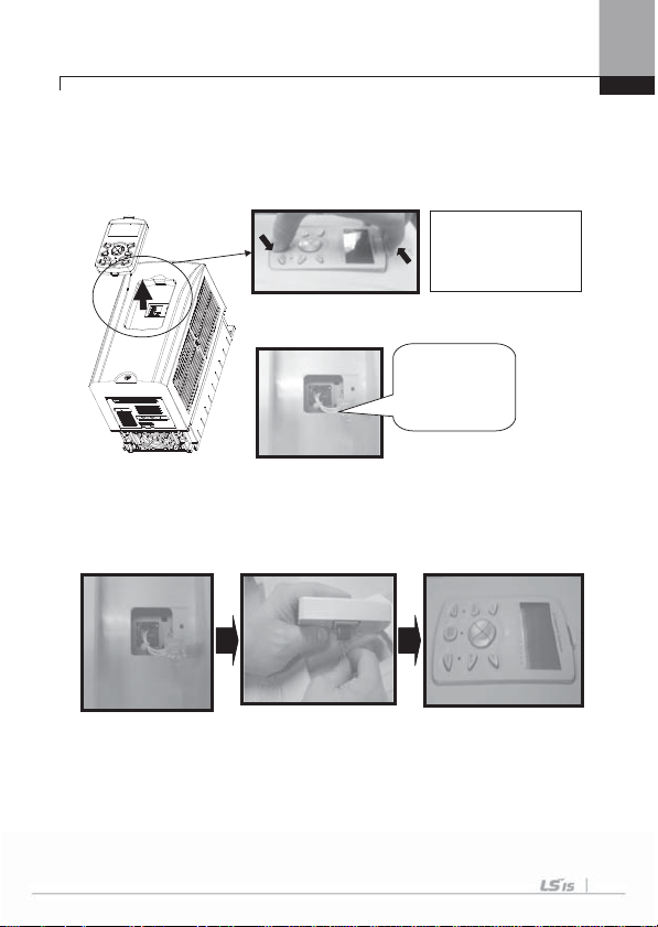
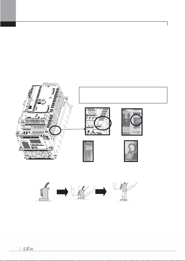
4.1.1 How to separate front cover when wiring
Remove Keypad on the product and release fixed volt of the lower end of up cover.
1) How to separate Keypad
Under pressing the
lower end of keypad,
pull the upper part of
keypad.
Connection wire
for Loader when
keypad is
disconnected.
2) How to assemble plug when connecting Keypad
As showing figures below, install the keypad after connecting the plug.
4-3

Chapter 4 Wiring
3) How to separate front cover
[IP21 Type]
Separate
front cover
I/O board control
circuit Terminal
releasing
the fixed
bolt.
[IP54 Type]
Separate the transparent keypad cover releasing fixed bolt and then separate keypad.
Separate the front cover releasing fixed bolt.
Before wiring, IP54 product must be installed on the panel.
Power circuit
terminal
4-4
Keypad
cover
fixed
bolt
Front
cover
fixed
bolt
Keypad fixed cover
Keypad
Wiring hole
Built-in
circulation
fan

Chapter 4 Wiring
4.1.2 How to separate front cover when wiring
(90~375 kW 400V, 30-75kW 200V)
Releasing the right/left fixed bolt on the lower front cover and get down the lower front
cover and then open it. Now, you can wire power part (R/S/T, P/N, U/V/W) and signal
cable (terminal block, encoder option, communication option, PLC option etc.).
4-5
Chapter 4 Wiring
4.1.3 Built-in EMC Filter
The product which has a built-in EMC filter is efficient for reducing conductive and
radiated noise from the input part of inverter. Turns On the On/Off switch of EMC filter to
perform the EMI function if you are select the product which has a built-in EMC filter.
(However, when unable to use EMC filter or due to the asymmetric structure of the
ground to use, EMC filter of on/off swich is set to off
1) How to set EMC Filter functions (Less than 7.5kW Products)
- Cut off plastic cover which marked below.
- If short circuit connector is connected with SW1
which is inside, EMC Filter works.
2) How to remove EMC Filter ON/OFF connector (Less than 7.5kW Product)
EMC filter OFF EMC filter ON
EMC filter ON EMC filter OFF
Check the voltage by a tester in 10minute after cutting the power supply. In case
separate with connector, pull the connector while pressing fixed hasp. When reinstalling,
be sure to hook the hasp of the connector. (If it is hard to separate them, please use
radio pincher or tweezers.)
4-6
Chapter 4 Wiring
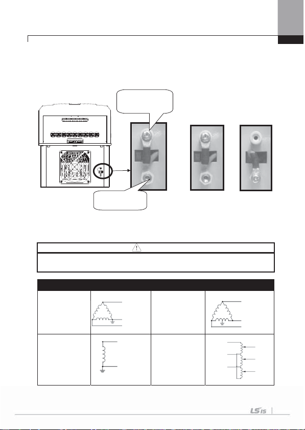
3) How to set EMC Filter functions (11~22kW Products)
EMC filter ON/OFF set terminal is located in lower part of the 11~22KW Terminal as
shown figure below. Initial set isON. When the green wire is connected in upper metal
connection terminal, EMC filter is ON and EMC filter is OFF if it is connected in
insulated connection terminal.
Metal terminal for
EMC filter ON
EMC filter has effect in reducing air electronic wave while being used in power source of
symmetrical ground method. Be sure to use EMC filter in symmetrical ground method
such as Y connection.
Insulated
terminal for EMC
EMC filter ON EMC filter OFF
Caution
Leakage current increases while EMC filter is ON. Do not use EMC filter when the
input is asymmetrical way such as Delta connection. It may cause an electric shock.
Asymmetrical Ground structure
1-phase is
grounded in
Delta
connection
Grounded in
1-phase end
R(L1)
S(L2)
T(L3)
L
N
Grounded middle
tap of 1-phase in
Delta connection
Non-grounded
3-Phase
connection
R(L1)
S(L2)
T(L3)
R(L1)
S(L2)
T(L3)
R(L1)
S(L2)
T(L3)
4-7

Chapter 4 Wiring
4.1.4 Wiring precaution
1) The internal circuits of the inverter will be damaged if the incoming power is connected
and applied to output terminals (U, V, W).
2) Use ring terminals with insulated caps when wiring the input power and motor wiring.
3) Do not leave wire fragments inside the inverter. Wire fragments can cause faults,
breakdowns, and malfunctions.
4) For input and output, use wires with sufficient size to ensure voltage drop of less than
2%. Motor torque may drop of operating at low frequencies and a long wire run
between inverter and motor.
5) The cable length between inverter and motor should be less than 150m (492ft). Due to
increased leakage capacitance between cables, overcurrent protective feature may
operate or equipment connected to the output side may malfunction. [But for products
of less than 3.7kW, the cable length should be less than 50m (164ft).]
6) The main circuit of the inverter contains high frequency noise, and can hinder
communication equipment near the inverter. To reduce noise, install line noise filters
on the input side of the inverter.
7) Do not use power factor capacitor, surge killers, or RFI filters on the output side of the
inverter. Doing so may damage these components.
8) Always check whether the LCD and the charge lamp for the power terminal are OFF
before wiring terminals. The charge capacitor may hold high-voltage even after the
power is disconnected. Use caution to prevent the possibility of personal injury.
9) Do not connect with MC at output pare of inverter and make MC On/Off during
operation. It can cause the Trip or damage of inverter.
10) When using a DC common with 30~75kW product, please be careful.
30~75kW product provides P1(+) and P2(+) terminal. In the case of DCR type of
product, P1(+) terminal is before reactor and P2(+) terminal is after reactor.
Therefore When using DC Common, you mush use P2(+) and N.
So, inevitablely to use DC Common, before using that, you muse contact with sales
team in advance. Because various matters need to be considered except for wiring.
Similary, when you connected to an external braking unit, you must use P2(+) and N
terminal.
Otherwise, products can be damaged(ex. Using P1(+) and N Terminal)
4.1.5 Grounding
1) The inverter is a high switching device, and leakage current may flow. Ground the
inverter to avoid electrical shock.
2) The ground impedance for 200V class is 100 ohm or less and 400V class 10ohm or less .
3) Connect only to the dedicated ground terminal of the inverter. Do not use the case or
the chassis screw for grounding.
4) As a minimum, grounding wire should meet the specifications listed below. Grounding
wire should be as short as possible and should be connected to the ground point as
near as possible to the inverter.
4-8

Chapter 4 Wiring
G
S
G
G
r
Inverter Capacity
Grounding wire size ( mm²)
200V class 400V class
0.75 ~ 3.7kW 3.5 2
5.5 ~ 7.5 kW 5.5 3.5
11 ~ 15 kW 14 8
18.5 ~ 22 kW 22 14
30 ~ 45 kW 22 22
55 ~ 75 kW 38 38
90 ~ 110 kW - 60
132 ~ 220 kW - 100
280 ~ 315 kW - 185
375 kW - 240
4.1.6 Terminal wiring diagram (POWER terminal block)
1) Wiring of Inverter below 7.5kW
Ground
terminal
G
R(L1)
(L2)
T(L3)
External
Fuse
2) Wiring of 11~22kW Product
3Phas e
AC
3-phase AC input
power supply
P(+)
BG
N(-)G
Dynamic brake resistor
R(L1) S(L2) T(L3) P(+) B N(-) U V W
3) Wiring of 30~75kW Product
R(L1) S(L2) T(L3) P1(+) P2(+) N(-) U V W
VG WG
IM
Moto
4-9

Chapter 4 Wiring
4) Wiring of 90~160kW Product
R(L1) S(L2) T(L3) P2(+) N(-) U V W
5) Wiring of 185~220kW Product
R(L1) S(L2) T(L3) P2(+) N(-) U V W
6) Wiring of 280~375kW Product
R(L1) S(L2) T(L3) P1(+) P2(+) N(-) U V W
Note
Products over 11kW have a linear arrangement of terminal blocks. Products for
0.75~22kW have built-in DC Reactor, so it does’t necessary any other DC Reactor
connection. Ground terminal must be grounded. Do not use ground to command for
ground cable, welding machine and power machine etc. Ground cable must be wire as
short as possible. If ground terminal of inverter is far from the inverter,electric potential
of inverter terminal ground can be unstable because leakage current of inverter can be
gernerated form inverter.
4-10
Chapter 4 Wiring
A
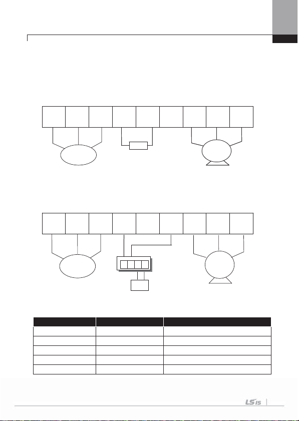
4.1.7 Terminals of main circuit
1) 0.75 ~ 22 kW (200V/400V)
(1) Built-in dynamic braking unit used
Connect P(+) and B terminal of inverter to the dynamic braking unit when built-in
dynamic unit is used.
R(L1) S(L2) T(L3) P(+) B N(-) U V W
Connects P(+) terminal of inverter to P/(+) terminal of the dynamic braking unit and
3 Phase
C Input
(2) Optional dynamic braking unit used
N(-) terminal of inverter to N/(-) terminal of the dynamic braking unit. B terminal of
inverter is not used.
R(L1) S(L2) T(L3) P(+) B N(-) U V W
DBR
Dynamic Brake
Resistor
Motor
ۡ
ۡ
ۡ
ۡ
ۡ
3 Phase
AC Input
P
ۡ
N
B1 B2
DB
Dynamic
Braking Unit
Dynamic Brake
Resistor
Motor
Terminal Symbol Terminal Name Description
R(L1),S(L2),T(L3) AC power supply input Connects normal AC input
P(+) (+) DC voltage terminal (+) DC link voltage terminal
N(-) (-) DC voltage terminal (-) DC link voltage terminal.
P(+),B Dynamic brake resistor Connects dynamic brake resistor.
U,V,W Inverter output Connects the 3 phase induction motor
4-11

Chapter 4 Wiring
2) 30 ~ 75 kW (200V, 400V)
R(L1) S(L2) T(L3) P1(+) P2 N(-) U V W
3 Phase
AC Input
DBU
Terminal Symbol Terminal Name Description
R(L1), S(L2), T(L3) AC power supply input Connects normal AC input
P1(+) (+)DC voltage terminal
P2, N(-)
N(-) (-)DC voltage terminal (-)DC link voltage terminal.
U, V, W Inverter output
1)
When using this terminal as a DC common, special considerations are required.
Dynamic brake unit
connection,
DC common terminal
N
B1
B2
P
Motor
DBR
(+)DC link voltage terminal,
It is located in front of DCL terminal.
Voltage terminal connecting Dynamic
brake unit, DC common terminal
1)
Connects the 3-phase induction
motor.
Be sure to consult with our sales representative.
Remark
Pay close attention when using 30~75W product for DC Common.
Buying DC reactor from the outside, it can not be installed with 30~75kW product. If you
want to use DC reactor of product, please purchase type of 30~75kW product mounted
with DC reactor. P1(+) terminal is at the Reactor’s front end while P2(+) terminal at its
back-end.
In the event of using such other DCR-mounted product for DC Common, you must use
P2(+) and N(-) terminals without fail. When using P1(+) and N(-) terminals for DC
Common, it may casue damage to the product.
Use for DC Common requires several considerations besides wiring. Therefore, in the
event it should be used for DC Common inevitably, be sure to contact our Sales
Department in advance.
Likewise, in the event of connecting with exterial braking unit, you must use P2(+) and
N(-) terminals without fail. When connecting with P1(+) and N(-) terminals, it may cause
damage to the product.
4-12

Chapter 4 Wiring
3) 90 ~ 160 kW (400V)
R(L1) S(L2) T(L3) P2(+) N(-) U V W
4) 280 ~ 375 kW (400V)
3 Phase
AC Input
Terminal Symbol Terminal Name Description
R(L1), S(L2), T(L3) AC power supply input Connects normal AC input
P(+) (+)DC voltage ternimal (+)DC link voltage terminal
N(-) (-)DC voltage terminal ( - )DC link voltage terminal
P(+), N(-)
U, V, W Inverter output
External brake unit
P N B1 B2
connection
Dynamic
brake unit
DBR
Dynamic
brake resistor
Voltage terminal connecting Dynamic
brake unit.
Connects the 3-phase induction
motor.
Motor
R(L1) S(L2) T(L3) P1(+) P2 N(-) U V W
3 Phase
AC Input
DBU
Terminal Symbol Terminal Name Description
R(L1), S(L2), T(L3) AC power supply input Connects normal AC input
P1(+) (+)DC voltage terminal
P2, N(-)
N(-) (-)DC voltage terminal (-)DC link voltage terminal.
U, V, W Inverter output
1)
When using this terminal as a DC common, special considerations are required.
Dynamic brake unit
connection,
DC common terminal
N
B1
B2
P
Motor
DBR
(+)DC link voltage terminal,
It is located in front of DCL terminal.
Voltage terminal connecting Dynamic
brake unit, DC common terminal
1)
Connects the 3-phase induction
motor.
Be sure to consult with our sales representative.
4-13
Chapter 4 Wiring
2)
²
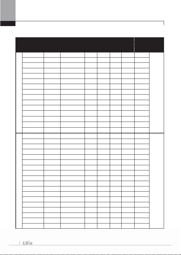
4.1.8 Specifications of power terminal block and Exterior fuse
Inverter applied
Terminal
Screw
size
Screw torque
1)
(Kgf·cm)
Cable
mm
AWG
R,S,T U,V,W R,S,T U,V,W Current Voltage
0.75 kW M4 7.1~12 2.5 2.5 14 14 10A
1.5 kW M4 7.1~12 2.5 2.5 14 14 15A
2.2 kW M4 7.1~12 2.5 2.5 14 14 20A
3.7 kW M4 7.1~12 4 4 12 12 32A
5.5 kW M4 7.1~12 6 6 10 10 50A
7.5 kW M4 7.1~12 10 10 8 8 63A
2
11 kW M6 30.6~38.2 16 16 6 6 80A
0
15 kW M6 30.6~38.2 25 22 4 4 100A
0
18.5 kW M8 61.2~91.8 35 30 2 2 125A
V
22 kW M8 61.2~91.8 35 30 2 2 160A
30 kW M8 61.2 ~ 91.8 70 70 1/0 1/0 200A
37 kW M8 61.2 ~ 91.8 95 95 2/0 2/0 250A
45 kW M8 61.2 ~ 91.8 95 95 2/0 2/0 350A
55 kW M10 89.7 ~ 122.0 120 120 3/0 3/0 400A
75 kW M10 89.7 ~ 122.0 150 150 4/0 4/0 450A
0.75~1.5kW M4 7.1~12 2.5 2.5 14 14 10A
2.2 kW M4 7.1~12 2.5 2.5 14 14 15A
3.7 kW M4 7.1~12 2.5 2.5 14 14 20A
5.5 kW M5 24.5~31.8 4 2.5 12 14 32A
7.5 kW M5 24.5~31.8 4 4 12 12 35A
11 kW M5 24.5~31.8 6 6 10 10 50A
15 kW M5 24.5~31.8 16 10 6 8 63A
18.5 kW M6 30.6~38.2 16 10 6 8 70A
22 kW M6 30.6~38.2 25 16 4 6 100A
4
30~37 kW M8 61.2~91.8 25 25 4 4 125A
0
45 kW M8 61.2~91.8 70 70 1/0 1/0 160A
0
55 kW M8 61.2~91.8 70 70 1/0 1/0 200A
V
75 kW M8 61.2~91.8 70 70 1/0 1/0 250A
90 kW M12 182.4~215.0 100 100 4/0 4/0 350A
110 kW M12 182.4~215.0 100 100 4/0 4/0 400A
132 kW M12 182.4~215.0 150 150 300 300 450A
160 kW M12 182.4~215.0 200 200 400 400 450A
185 kW M12 182.4~215.0 200 200 400 400 620A
Exterior fuse
500V
500V
4-14

Chapter 4 Wiring
2)
²
Inverter applied
Terminal
Screw
size
Screw torque
(Kgf·cm)
1)
mm
Cable
AWG
Exterior fuse
R,S,T U,V,W R,S,T U,V,W Current Voltage
220 kW M12 182.4~215.0 250 250 500 500 800A
280 kW M12 182.4~215.0 325 325 650 650 1000A
315 kW M12 182.4~215.0 2x200 2x200
375 kW M12 182.4~215.0 2x250 2x250
1) : Apply the prescribed torque for the terminal screws. If the screws are loose, it might cause a
failure.
2) : Use 600V 75 copper cable.
The entire cable length should be below 150m. In case of connection of the motor, the entire
length should not exceed 150m because if a motor is connected from a remote location, the
over current protection function might be started by the harmonics caused by the floating
volume increment within the cables or a failure of the device connected to the secondary side
might occur. The entire cable length should be below 150m too when you connect more than
one motor. Do not use a triplex cable in case of distance wiring. (50m when below 3.7KW)
In case of lengthy wiring, Use thick wire in order to reduce line voltage drop and decrease the
carrier frequency or use a micro surge filter.
Line Voltage Drop [V] = (¥3 X wire resistance [mȍ/m]X wire length [m] X Current [A])/1000
Distance between inverter and motor Up to 50 m Up to 100 m Over 100 m
2x40
2x50
0
0
2x400 1200A
2x500 1400A
Permitted carrier frequency Below 15 kHz Below 5 kHz Below 2.5 kHz
Note Short Circuit Rating
Suitable for use on a circuit capable of delivering not more than 5,000 rms Symmetrical
Amperes, 240 or 480 Volts Maximum. When protected by a circuit breaker having an
interrupting rating not less than 100,000 rms symmetrical amperes, Suitable for use on a circuit
capable of delivering not more than 100,000 rms Symmetrical Amperes, 480 Volts Maximum.
4-15

Chapter 4 Wiring
)
4.1.9 Control terminal line diagram (Basic I/O terminal block, below 22kW)
NPN (Sink)
/PNP (Source) set terminal
I / PTC
set terminal
TR
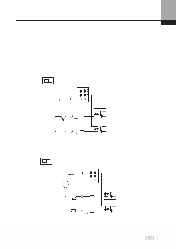
1) How to set NPN (Sink)/PNP (Source)
iS7 serves 2 sequence input terminals of control circuit: NPN mode (Sink mode)
and PNP mode (Source mode). It is possible to change the logic of input terminal with
NPN mode (Sink mode) and PNP mode (Source mode) by using NPN (Sink)/PNP
(Source) set terminal. Each mode connecting methods are follows.
(1) NPN mode (Sink mode)
Set NPN (Sink)/PNP (Source) switch into NPN. CM (24V GND) is common terminal of
contact point input signal. Initial set of Factory default is NPN mode (Sink mode).
PNP
NPN
NPN mode (Sink mode)
CM (24G)
Inner source (24V)
P1(FX
P2 (RX)
4-16
Chapter 4 Wiring
+
(2) PNP mode (Source mode) – When use inner source
Set NPN (Sink)/PNP (Source) switch into PNP. 24 (24V inner source) is common
terminal of contact point input signal. PNP mode (Source mode) – Set NPN (Sink)/PNP
(Source) switch into PNP When use exterior source.
If you want try to use exterior 24V source, connect exterior source (-) terminal with CM
(24V GND).
PNP
NPN
PNP mode (Source mode) – When using inner source
Inner source (24V)
24(24V)
P1(FX)
P2(RX)
NPN PNP
External
Source (24V)
PNP mode (Source mode) – When using external source
CM (24G)
-
P1(FX)
P2(RX)
4-17
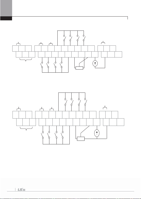
Chapter 4 Wiring
A
p
1) 0.75 ~ 22kW (Basic I/O)
Relay2
(Normal
Open)
A1
Relay1
(Normal Open)
C1
NC A2
B1
Open
Collector
Output
Q1
EG
Digital contact point
input
(NPN/PNP,
Sink/Source mode
24V
power
supply
P6 P5
P1
CM
24
P7
CM P8
P4 P3
P2
In case of analog
voltage input with
potentiometer
(-10V~+10V
input)
5G
I1 V1 VR- VR+
In case of
analog
current input
(4~20 mA
input)
Relay2
(Normal
Open)
A1
NC A2
B1
C1
Relay1
(Normal Open)
TR terminal is RS485 communication terminal resistor (120 ).
We recommend the potentiometer for 1/2W, 1k ..
Open
Collector
Output
Q1
EG
P5
Digital contact point
input
(NPN/PNP,
Sink/Source mode
support)
24V
power
supply
P6
VR- VR+
P4 P3
5G
I1 V1
In case of
analog current
input
(4~20 mA
input)
24
CM
P7
P8
P1
CM
P2
In case of
analog
voltage input
with
potentiometer
(0V~+10V
input)
* Description of TR terminal and variable resistence are same as those of insulated
I/O.
4-18
S+
Port
5G
Port
S+
RS485
S- C2
CM
AO1
0~10V Output
RS485
S- C2
AO1
5G
AO2
0~20mA Output
4~20m
Out
ut
CM
AO2
0~10V Output
0~20mA Output
4~20mA Output

R
Port
pply
4.1.10 Control terminal line diagram
(Insulated I/O terminal block, above 30kW)
1) 30~375kW (Insulated I/O)
Relay2
(Normal
Open)
A1
Relay2
(Normal
Open)
A1
Relay1
(Normal Open)
TR terminal is RS485 communication terminal resistor (120 ).
We recommend the potentiometer for 1/2W, 1k .
NC A2
C1
Relay1
(Normal
Open)
C1
NC A2
B1
B1
Open
Collector
Output
Q1
Open
Collector
Output
24V
power
supply
24 EG
P6 P5
Digital contact point
input (NPN/PNP,
Sink/Source mode
support)
24V
power
su
Q1
24 EG
P6 P5
Digital contact point
input
(NPN/PNP,
Sink/Source mode
support)
CM
P7
CM
P7
NPN (Sink)/PNP
(Source)Set terminal
P1
P2
CM P8
In case of
analog voltage
input with
potentiometer
(0V~+10V input)
P1
P2
CM P8
In case of
analog voltage
input with
potentiometer
(-10V~+10V input)
P4 P3
P4 P3
Chapter 4 Wiring
T
I / PTC
Set terminal
RS485
5G
S- C2
CM
S+
AO1
0~10V Output
In case of
analog
current
input
(4~20 mA
input)
CM
S+
CM I1 V1 VR- VR+
In case of
analog
current
input
(4~20 mA
input)
RS485
Port
5G
S- C2
AO1
0~10V Output
AO2 CM I1 V1 VR- VR+
0~20mA Output
4~20mA Output
AO2
0~20mA Output
4~20mA Output
4-19

Chapter 4 Wiring
When setting the frequency reference source with analog voltage (V) or current (I), the
reflection of frequency for the analog input is based on when the analog input is actually
received. Taking the voltage input for instance, the state no voltage is applied to V1 is not
0V, but 0V is input to V1 in fact is 0V
In case of analog voltage input, accurate linear property is shown by Bipolar at the state 10 ~ 0 ~ 10V input is received while by Unipolar at the state 0 ~ 10V input if received.
Warning: If the analog voltage input is interrupted with the frequency reference source at
the state of analog voltage input, i.e. if no voltage is applied, it may cause the occurrence
of offset voltage enabling the frequency command approx. 4~5Hz.
4-20

4.1.11 Control circuit terminal
r
A
1) Contact point start function selection
Contact
point start
functon
selection
Input Signal
Frequency
Output Signal
Terminal
Type
Contact
Symbol
P1~P8
VR(+)
VR(-)
Analog
A01
Analog
A02
A1, B1, C1 Fault signal output
Point
A2, C2
S+,S-, CM
CM
V1
I1
5G
Q1
EG
24 Exterior 24Vpower Maximum output current: 150mA
Chapter 4 Wiring
Terminal Name Terminal Description
Multi-function
input1~8
Sequence
common terminal
Frequency setting
Power (+) terminal
Frequency setting
(-) terminal
powe
Frequency setting
(voltage)
Frequency setting
(current)
Frequency setting
common terminal
Multi-function
analog voltage
output terminal
Multi-function
analog current
output terminal
Multi-function
terminal
(open collector)
Common terminal
for open collector
Multi-function
relay 2 output A
contact point
RS-485 signal
input terminal
Available by defining as multi-function input
Common terminal of the contact point input terminal
(note : In case of Basic I/O, common terminal is different
from the 5G common terminal)
Power supply for analog frequency setting
Maximum output is +12V, 100mA.
Power supply for analog frequency setting
Maximum output is -12V, 100mA.
Becomes set frequency with input of DC -10~10V.
Unipolar 0~+10[V]),Biopolar(-10[V] ~10[V])
input resistance 20kȍ
Becomes set frequency with input of DC 0~20m
input resistance 249ȍ
Common terminal of analog frequency setting signal and
analog voltage and current terminals
note :
In case Basic I/O, common terminal are different
(
from the CM common terminal.)
Select the one among Output frequency, Output current,
DC voltage.
- Ouput voltage : 0~10V
- Maximum output voltage : 10V
- Maximum output current: 10mA
Select the one among Output frequency, Output
current,Output voltage, DC voltage.
- Output current: 4~20mA (0~20mA)
- Maximum output current: 20mA
DC 26V, below 100mA
External power supply common earth terminal of the
open collector
Protection function is activated to break output.
(below AC 250V 5A, DC 30V 5A)
- Fault signal : A1-C1 electrified (B1-C1 unelectrified)
- Normal signal : B1-C1 electrified (A1-C1 unelectrified)
Output the signal while running. User defined multi-
function output terminal.
(below AC 250V 5A, DC 30V 5A)
RS-485 signal line
(Refer to ‘Communication Function’ contained in iS7 User
Manual. You can download it from LSIS website.
(http://www.lsis.biz
version of iS7 User Manual.
). This provided manual is the simple
4-21

Chapter 4 Wiring
)
A
(+)
y
g
A
A
(-)
y
g
A
A
)
(
y
g
4.1.12 Specifications of signal terminal block distribution
Type Name mm2 AWG
P1~P8 Multi-function input terminal
CM
VR+
VR-
V1
I1
AO1
AO2
5G
Q1
EG
24 External 24V power supply
A1
B1
C1
A2
C2
S+,S- RS485 signal input terminal
CM RS485 common terminal
1) Apply the shielded type of twisted-pare wire.
Do not use more than 3M remote cable for the keypad. Failure of the signals on the keypad might
occur. To prevent radiated emissions in the analogical and digital signals, you must put a ferrite in
the wires of these signals.
Ex. Brand Würth Elektronik ref. 74271132
Terminal Cable size 1)
Contact point common terminal
(In case of Basic I/O,
CM is different from 5G
nalog frequency setting
power suppl
nalog frequency setting
power suppl
Multi-function analog voltage
input terminal
Multi-function analog current input
terminal
Multi-function analog voltage
output terminal
Multi-function analog current
output terminal
Frequency setting common
terminal
(In case of Basic I/O,
5G is different from CM
Multi-function terminal
open collector)
Earth terminal for external power
suppl
Multi function relay 1
output A contact point
Multi function relay 1
output B contact point
Multi function relay 1
contact point common terminal
Multi function relay 2
output A contact point
Multi function relay 2
contact point common terminal
~1.25
~1.25
0.33
16~22
0.33
14~22
~2.0
0.33
16~22 Maximum output current : 150mA
0.33
14~22
~2.0
2
0.75mm
(18AWG)
Caution
Electric specifications
-
Common earth for multi function input
terminal
Output voltage : +12V
Maximum output volta
Output voltage : -12V
Maximum output volta
Input voltage : 0~10V or -10~10V
0~20mA input
Internal resistance : 249ȍ
Maximum output voltage : 10V
Maximum output current : 10m
Maximum output current : 20mA
Common terminal of analog frequency
setting signal and analog current and
voltage terminals
DC26V, below 100mA
Below AC250V/5A, Below DC30V/5A
Below AC250V/5A, Below DC30V/5A
Below AC250V/5A, Below DC30V/5A
Below AC250V/5A, Below DC30V/5A
Below AC250V/5A, Below DC30V/5A
RS485 signal line
For multi connection, RS485 power
round(Shield) connection terminal
e : 100m
e : 100m
4-22

Chapter 4 Wiring
p
p
o
4.2 Operation Checking
IS7 provides EASY START MODE helping with the basic parameter setting using the
keypad by distribution shown above when power is first supplied.
4.2.1 Easy start
Easy Start gets started when power is first supplied after you purchase the product or
power is re-supplied after the set parameters are all initialized.
- Easy Start Mode gets started first even in case of an inverter trip.
- Easy Start Mode does not operate during the inverter running.
4.2.2 Easy start operation
It operates in the following sequence.
Start Easy Set
CNF-01 Language Sel
DRV-14 Motor Capacity
BAS-11 Pole Number
BAS-15 Rated Volt
BAS-10 60/50 Hz Sel
BAS19 AC Input Volt
DRV-06 Cmd Source
DRV-01 Cmd Frequency
You can go Monitor
Mode if select “N
2. Select the language displayed on the KEYPAD.
(Only English is available now.)
3. Set the motor capacity used. (EX: 0.75KW, 1.5KW)
4. Set the number of poles of the motor.
5. Set the rated voltage of the motor used.
(Of the set values, 0V refers to the voltage equal to the
inverter in
ut voltage)
6. Set the rated frequency of the motor used.
7. Set the inverter in
8. Set the operation command method.
(EX:KEYPAD, FX/RX-1, FX-RX-2, etc.)
9. Set the command frequency. (EX: 50Hz, 60Hz, etc.)
1. Select whether to choose
”
Easy Start.
ut voltage.
*
You can move to Monitor Mode by pressing ESC at any time while you set the Easy
Start mode.
4-23
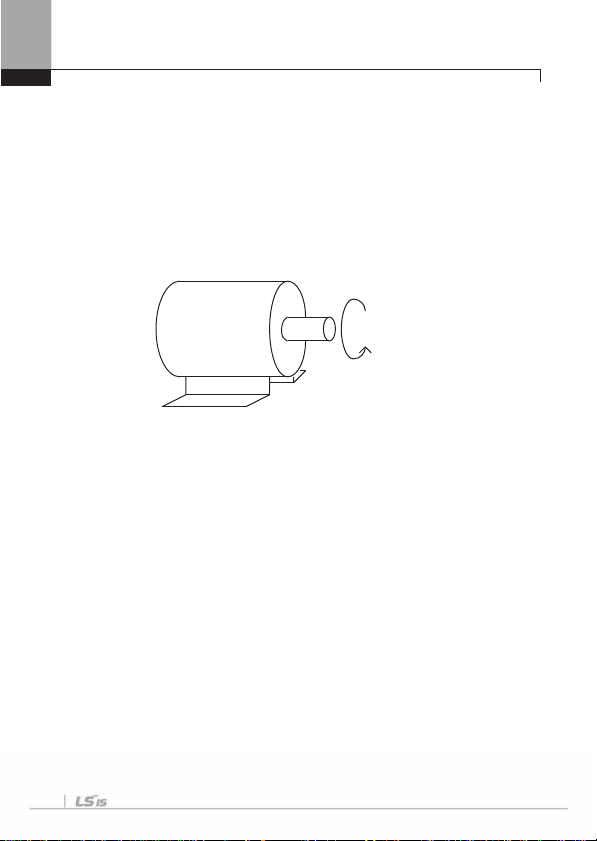
Chapter 4 Wiring
4.2.3 Checking for normal working
1) Motor forward/reverse direction and Normal working checking by KEYPAD operation
After setting Cmd Source of DRV-06 is 0 : Keypad, Freq Ref Src of DRV-07 is 0 :
Keypad-1 and set DRV-01 : Cmd Frequency into temporary speed, Command forward
operation by pressing FWD please. At this time, shaft of motor at the side of load rotates
into counterclock wise direction. Otherwise, it must be changed 2 terminals among the
inverter output terminal U, V, W.
Forward
direction
Operation
4-24
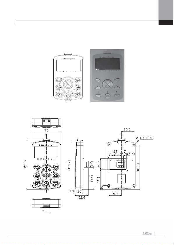
Chapter 5 How to Use Keypad
5.1 How to Use Keypad
5.1.1 Standard KEYPAD appearance and description (Graphic keypad)
Standard Keypad is used in Inverter parameter setting, Monitor display and
Inverter operations.
1) Dimensions
5-1

Chapter 5 How to Use Keypad
y
2) Key Functions
14. Move to UP
1. Cancel(ESC)
2. Move to Left
3. MODE selection 11. Multi-Function
4.Reverse operation
5. Reverse operation
6. Stop Indication LED
13. PROGRAM set
12. Move to Right
10. Move to down
9. Forward operation LED
8. Forward operation
7. STOP/RESET
Section Buttons Key Name Function Description
Mode Key - Change MODE
- Write, change and save data in
parameter codes.
- Used when writing data or move
codes.
- Movement among groups.
- Movement of cursor in writing.
- Register Jog or User codes.
- In writing, it is possible to use
saved data previously if press this
button before pressing Program
Key.
- Move to first code when code
moving is required in a group.
- Move to Monitor mode when
Mode moving.
KEY
Program Key
Up ke
DownKey
Left/Right Key
Multi Function
Key
Cancel Key
Forward Key - Motor rotates Forward direction.
Reverse Key - Motor rotates Reverse direction.
Stop/Reset Key
- Stop Under operating.
- Trip release when a trip occurs.
5-2

3) Composition of Display
M
g
5
(1) Monitor Mode
Operating/Frequency
Mode Display
Monitor
MON T/K N STP 0.00Hz
Chapter 5 How to Use Keypad
Multi-function Key
Inverter Operating Status
Status Display Item
Monitor Mode
Display Item 1
Monitor Mode
Display Item 2
Monitor Mode
Display Item 3
Group Display
Code No. and Name
Initial Value at the time of
(2) Parameter change display
Mode Display
Product Delivery
R DRV N STP 0.00Hz
Cmd Frequency 0.00Hz
0 ~ 60.00 Hz
:0.00 C:10.00
ulti-function Key Settin
Inverter Operating Status
Status display Item
Parameter Value
Settable Range
Currently Set Value
4) Display Item List
(1) Mode Display Items : see “Mode shift” on this chapter 5.1.3.
(2) Group Display Items : see “Group shift” on this chapter 5.1.4.
(3) Operation Command/Frequency Command Display Items (Type of Seq and
number of steps are displayed during auto sequence operation
5-3

Chapter 5 How to Use Keypad
(4) Monitor Display Items
No Function Display Description
Mode
1
Display
Operating
2
Command
Frequency
3
Command
Multi
Function
4
Key
Setting
5 Inverter STP Motor stopped
MON Monitor Mode
PAR Parameter Mode
U and M USR & Macro Mode
TRP Trip Mode
CNF
K Keypad operation command
O FBus Option operation command
A Application Option operation command
R Built-in 485 operation command
T Terminal block operation command
K Keypad frequency command
V V1 input frequency command
I I1 input frequency command
P Pulse input frequency command
U
D
S
O FBus Option frequency command
X
J Jog frequency command
R Internal 485 frequency command
1~9 A~F Sequential frequency command
JOG Key Used for shift to Keypad JOG mode
Local/Remote
UserGrp
SelKey
Config Mode
Frequency command during UP
operation (Up-Down operation)
Frequency command during DOWN
operation (Up-Down operation)
Frequency command during STOP
operation (Up-Down operation)
V2, I2 frequency command of sub-
terminal block
Used to select local or remote
operation
Used to register parameters as a user
group in the parameter mode or delete
parameters in the user group.
5-4

Chapter 5 How to Use Keypad
No Function Display Description
Operating
Status
FWD Operating forward
REV Operating reversely
DC DC output
WAN Warning
STL Stalling
SPS Speed Search
OSS SW OC controlled
OSH HW OC controlled
TUN Auto Tuning
(5) Status Display Items: see “Operating status monitoring” on this chapter 5.1.7.
(6) Monitor Mode Display Items: see “Operating status monitoring” on this
chapter 5.1.7.
5-5

Chapter 5 How to Use Keypad
5.1.2 Menu composition
SV-iS7 series inverter consists of the following 5 modes. Each mode has its
own function items suitable for the properties and especially the parameter
mode displays the functions necessary for inverter operation in groups.
Group movable by MODE Key
Ex) MonitorParameter
Movable by left / right key in
Parameter Group
Ex) DriveBasic Function
G
Monitor
Parameter
Monitor
Output Terminal
Application Option
User &Macro
Basic
Function
Advanced
Function
Control
Input Terminal
Communication
Application
Card
Protection
Para-
meter
Drive
Mode Display Description
Monitor
mode
Parameter
mode
User and
Macro mode
MON
U and M
Displays information on the operating status of the
inverter. Can monitor frequency setting, operating
frequency display, output current and voltage, etc.
Can set functions necessary for operation. Divided
PAR
into a total of 12 groups, each suitable for the
functional difficulty and objective.
You can group only necessary functions by using
user group and macro group. This is not displayed
when the user code is not registered or when the
user/macro mode shifts with the mode key unless
the macro is not selected.
Trip
User &
Macro
AUT
Config
Config
Trip
User
Macro1
Macro
2
M2
5-6

Chapter 5 How to Use Keypad
Mode Display Description
In case of a failure during operation, the failure
type and information on the operating
Trip mode TRP
Config mode CNF
frequency/current/ voltage at the time of the failure
occurring are displayed. You can also monitor the
type of the trips that previously occurred. Trip
Mode is not displayed when there is no previous
failure history during normal operation.
You can set the use environment for the inverter
itself that is not directly related to operating
functions such as keypad language selection,
monitor mode environment selection, display of
the option card type mounted on the inverter,
parameter initialization and copying.
1) Parameter mode
Mode
Drive group DRV
Basic group BAS
Advanced
function
group
Control
function
group
Input terminal
function
group
Output
terminal
function
group
Communicati
on function
group
Application
function
group
Auto
Sequence run
group
Display
Has functions necessary for operation including
frequency/acceleration/deceleration time setting
and operation command selection, etc.
Can set the basic functions such as the motor
parameter and sequential frequency, etc.
Can set the acceleration/deceleration pattern
ADV
and frequency control function, etc.
Can set functions related to sensorless and
CON
vector control.
Can set functions related to the inverter input
IN
terminal block including multi-function digital
input and analog input.
Can set the inverter output terminal block
OUT
functions such as the relay and analog output.
COM
Sets the functions related to built-in 485
communication and communication option card
in such a case.
Sets functions such as PID control and auto
APP
sequence operation.
This group is displayed if Auto Sequence Group
AUT
in APP is selected and sets the functions
necessary for auto sequence operation.
Description
5-7

Chapter 5 How to Use Keypad
Mode
Application
option group
Protection
group
Motor 2
function
group(Motor
2)
2) User and Macro mode
Group Display Description
User group USR
Macro group MCx
Display
APO
PRT
M2
Sets functions related to the encoder option and
PLC option card, if they are used.
Can set functions for protecting the motor and
inverter.
This group is displayed if you select Motor #2
among the multi-function input terminal functions
and sets functions related to Motor #2.
Of the function items of each group of the
parameter mode, the items that need to be
monitored or that are frequently set by the user are
grouped and displayed. It is registered by using the
multi-function key of the keypad.
The functions necessary for the inverter according
to the load type can be grouped and selected at the
time of delivery from the factory. If the user selects
a desired operation type, the groups displayed in
MC1 or MC2 are shown. You can select them in
CNF Mode. For more details, see 8-48 page, 8.1.31
Addition to Macro group in detailed user’s manual
from website.
Description
5-8
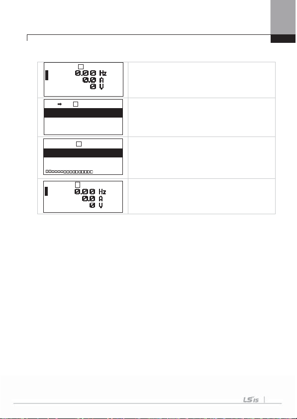
5.1.3 Mode shift
MON T/K N STP 0.00Hz
PARGDRV N STP 0.00Hz
00 Jump Code
9 CODE
01 Cmd Frequency
0.00 Hz
02 Cmd Torque
0.0 %
CNF N STP 0.00Hz
00 Jump Code
40 CODE
01 Language Sel
English
02 LCD Contrast
MON T/K N STP 0.00Hz
Chapter 5 How to Use Keypad
- Power on, a display emerges as shown on
the left. The present mode is the monitor
mode.
- Press Mode key once.
- You have shifted to Parameter Mode.
- Press Mode key once.
- You have shifted to Config Mode.
- Press Mode key once.
- You come back to Monitor Mode.
5-9
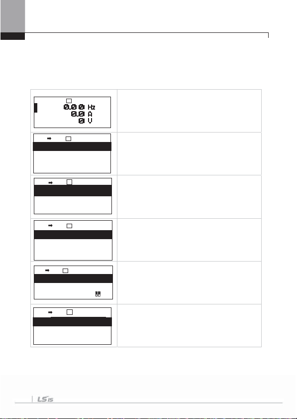
Chapter 5 How to Use Keypad
5.1.4 Group shift
1) Group Shift in Parameter Mode
If you press Right key in the Parameter Mode, the display changes as follows.
If you press Left key, the display order will be reversed.
MON T/K N STP 0.00Hz
PARGDRV N STP 0.00Hz
00 Jump Code
9 CODE
01 Cmd Frequency
0.00 Hz
Cmd Torque
02
0.0 %
PAR GBAS N STP 0.00Hz
00 Jump Code
20 CODE
01 Aux Ref Src
None
02 Cmd 2nd Src
Fx/Rx-1
PAR GADV N STP 0.00Hz
00 Jump Code
24 CODE
01 Acc Pattern
Linear
02 Dec Pattern
PAR GPRT N STP 0.00Hz
00 Jump Code
40 CODE
01 Load Duty
Heavy Duty
02 Phase Loss Chk
PARGDRV N STP 0.00Hz
00 Jump Code
9 CODE
Cmd Frequency
01
0.00 Hz
02 Cmd Torque
Linear
0.0 %
- Power on, a display emerges as shown on
the left. The present mode is the monitor
mode.
- Press Mode key once.
- You have shifted to Parameter Mode.
- The drive group of Parameter Mode is being
displayed.
- Press Right key once.
- You shift to Basic Function Group(BAS).
- Press Right key once.
- You shift to Advanced Function Group(ADV).
- Press Right Shift key 7 times.
- The group changed in sequence, PRT is
displayed.
- Press Right Shift key once.
- You come back to the Drive Group(DRV) of
Parameter Group.
5-10

Chapter 5 How to Use Keypad
01
Cmd F
5.1.5 Code (Function Item) shift
1) Code shift (function Items) in modes and groups
Using Up and Down keys: The following figures give an example of shifting the
code by using Up and Down keys in DRV and BAS of Parameter Mode. Code
shift in other modes are the same.
MON T/K N STP 0.00Hz
PARGDRV N STP 0.00Hz
00 Jump Code
00 Jump Code
9 CODE
1 CODE
01 Cmd Frequency
0.00 Hz
02 Acc Time
20.0 sec
PARGDRV N STP 0.00Hz
00 Jump Code
9 CODE
requency
01 Cmd Frequency
0.00 Hz
0.00 Hz
02 Acc Time
20.0 sec
PARGBAS N STP 0.00Hz
00 Jump Code
20 CODE
01 Aux Ref Src
None
04 Cmd 2nd Src
Fx/Rx-1
- Power on, the display emerges as on the
left. The present mode is Monitor Mode
(MON).
- Press Mode key once.
- The display shows DRV of Parameter Mode.
If DRV is not displayed, press Mode key
until DRV emerges or press ESC once.
- If you press Down key, you will shift to code
No. 0 in DRV of Parameter Mode as shown
on the left.
- Press Right key once.
- You shift to BAS of Parameter Mode.
- You can shift the code by using Up or Down
key.
5-11
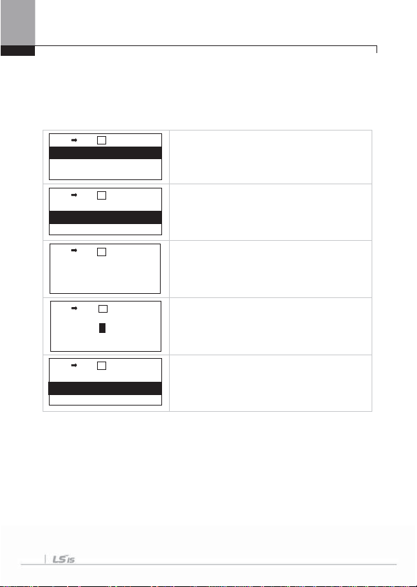
Chapter 5 How to Use Keypad
5.1.6 Parameter setting
1) Parameter setting in modes and groups
This gives an example of changing frequency in the Drive Group of Parameter
Mode. You can do so too in other modes or groups.
PARGDRV N STP 0.00Hz
00 Jump Code
9 CODE
01 Cmd Frequency
0.00 Hz
02 Cmd Torque
0.0 %
PARGDRV N STP 0.00Hz
00 Jump Code
9 CODE
01 Cmd Frequency
0.00 Hz
02 Cmd Torque
0.0 %
PARGDRV N STP 0.00Hz
01 Cmd Frequency
0.00 Hz
0.50 ~ 60.00 Hz
D:0.00 C:0.00
PARGDRV N STP 0.00Hz
01 Cmd Frequency
10.00 Hz
0.50 ~ 60.00 Hz
D:0.00 C:0.00
PARGDRV N STP 0.00Hz
00 Jump Code
9 CODE
01 Cmd Frequency
10.00 Hz
02 Cmd Torque
0.0 %
- This is the initial display of Parameter Mode.
- Press Down key.
- You have shifted to 01 frequency setting
code.
- Press PROG.
- The cursor flashes so that you can enter
frequency.
- If you want to set the frequency at 10Hz,
move the cursor to the desired place using
Left/Right keys.
- Enter 10Hz using Up key and press PROG.
- The desired frequency has been changed to
10Hz.
5-12

Chapter 5 How to Use Keypad
5.1.7 Operating status monitoring
1) Using monitor mode
You can monitor 3 items at a time in Monitor Mode. Some items including
frequency can be edited. Displayed items can be selected by the user in
Config Mode(CNF).
- This is the initial display of Monitor Mode.
MON T/K N STP 0.00Hz
1
CNF N STP 0.00Hz
21 Monitor Line-1
Frequency
22 Monitor Line-2
Output Current
23 Monitor Line-3
Output Voltage
CNF N STP 0.00Hz
21 Monitor Line-1
Frequency
22 Monitor Line-2
Output Current
23 Monitor Line-3
Output Power
MON T/K N STP 0.00Hz
Hz
A
kW
- The frequency, current and voltage are set as
the default monitor items at the time of product
delivery.
- Of the displayed items, for frequency, the goal
frequency is displayed during stop and
operating frequency during operation.
- You can set the items to display in Monitor
Mode in sequence at 21~23 in CNF.
- Move to 23 using Down key.
- Change the 23 item in Monitor Mode to output
power.
- The third displayed item in Monitor Mode has
been changed to output power.
5-13

Chapter 5 How to Use Keypad
Y\ {
2) Possible to monitoring items
Mode Code Function Display Setting Range Initial Value
CNF 20 Anytime Para 0 Frequency 0 : Frequency
21 Monitor Line-1 1 Speed 0 : Frequency
22 Monitor Line-2 2
23 Monitor Line-3 3
Output Current 2 :Output Current
Output Voltage
4 Output Power
5 WHour Counter
6 DCLink Voltage
7 DI State
8 DO State
9 V1 Monitor[V]
10 V1 Monitor[%]
11 I1 Monitor[mA]
12 I1 Monitor[%]
13 V2 Monitor[V]
14 V2 Monitor[%]
15 I2 Monitor[mA]
16 I2 Monitor[%]
17 PID Output
18 PID ref Value
19 PID Fdb Value
20 Torque
21 Torque Limit
22 Trq Bias Ref
23 Speed Limit
24 Load Speed
3 :Output Voltage
5-14
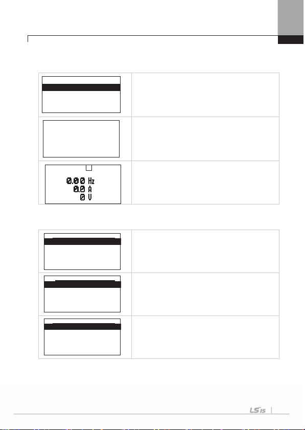
5.1.8 Failure status monitoring
1) Failure during operation
TRP current
Over Voltage (01)
01 Output Freq
48.30 Hz
02 Output Current
33.3 A
TRP Last-1
01 Output Freq
48.30 Hz
02 Output Current
03 Inverter State
33.3 A
Stop
MON T/K N STP
0.0A
2) Multiple failures at a time
TRP current
Over Voltage (02)
01 Output Freq
48.30 Hz
02 Output Current
00 Trip Name ( 2)
0 Over Voltage
1 Externa Trip
Over Voltage (02)
01 Output Freq
48.30 Hz
02 Output Current
33.3 A
TRP current
TRP current
33.3 A
Chapter 5 How to Use Keypad
- In case of a failure during operation, the
mode automatically shifts to Trip Mode and
the type of the current failure is displayed.
- If you press Down key, the output frequency,
current and operating status at the time of
the failure occurring are displayed.
- If the failure status is terminated by Reset,
the keypad before the failure comes back.
- In case of multiple failures, the number of
failures is displayed next to the failure type.
- Press PROG.
- The type of failures is displayed.
- Press PROG.
- The display mode before failure checking
comes back.
5-15

Chapter 5 How to Use Keypad
3) Saving and monitoring of failure history
Previous failures are saved in Trip Mode. Up to 5 failures can be saved.
Failure history is saved not only by Reset but also in case of a low voltage
failure due to power off.
If the number of failure exceeds 5, the failures before the latest 5 ones are
automatically deleted.
TRP current
Over Voltage (02)
01 Output Freq
48.30 Hz
02 Output Current
MON T/K N STP
TRP current
00 Trip Name ( 2)
Over Voltage
01 Output Freq
48.30 Hz
TRP current
00 Trip Name ( 1)
External Trip
01 Output Freq
48.30 Hz
5-16
0.0A
- In case of a failure during operation, the mode
automatically shifts to Trip Mode with the trip
displayed.
- If you press Reset or the terminal is entered,
the failure above is automatically saved and
the display goes back to the place before the
failure.
- Move to Trip Mode using Mode key.
- The most recent failure is saved in Last-1
code.
- Press Right key.
- A previous failure is saved in Last-2 code.
- If another failure occurs, what was in Last-2
moves to Last-3.
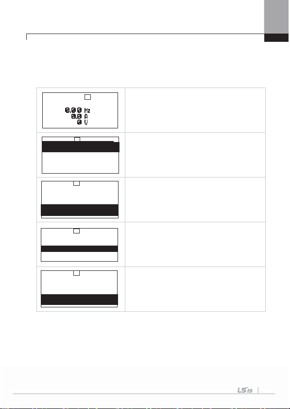
Chapter 5 How to Use Keypad
5.1.9 How to initialize parameter
You can initialize the parameter that has been changed by the user to the initial
state at the time of delivery. Not only the entire parameter but a group of the
parameter mode can be selected and initialized.
MON T/K N STP
0.0A
CNF N STP 0.0A
00 Jump Code
9 CODE
01 language Sel
English
02 Inv S/W Ver
Version 1.00
CNF N STP 0.0A
31 Option-2 Type
None
32 Option-3 Type
None
40 Parameter Init
----- No ------
CNF N STP 0.0A
40 Parameter Init
------ No ------
1 All Groups
2 DRV
CNF N STP 0.0A
31 Option-2 Type
None
32 Option-3 Type
None
40 Parameter Init
----- No ------
- Monitor Mode is displayed.
- Shift to CNF by using Mode key.
- Shift to code 40 using Down key.
- Press PR OG.
- Of the Parameter items to initialize, select All
Groups and press PROG.
- Initialization finished, you come back to the
initialization selection display.
5-17
Chapter 5 How to Use Keypad
5-18
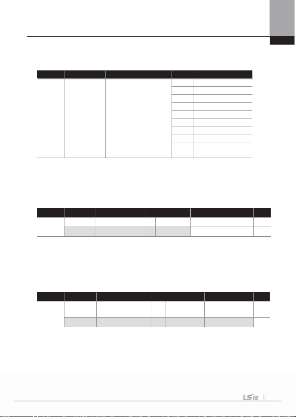
Chapter 6 Basic Functions
6.1 Basic Functions
6.1.1 How to set frequency (When you want to set frequency)
Group Code No. Function Display Initial Display
DRV 07 Freq Ref Src
Select the frequency setting method in code 07 of DRV Group. Digital setting by using
the keypad, analog setting by using voltage (V1) and current (I1) input of the control
terminal block and built-in RS485 port or communication option are available for
operating frequency setting from the external controller.
1) Frequency Setting Using Keypad 1 : KeyPad-1
Group Code No. Function Display Initial Setting Setting Range Unit
DRV
You can change the frequency by changing the frequency using the keypad and
pressing PROG .
Set DRV group 07 at KeyPad-1. The frequency changes is saved in the memory if you
change the frequency at DRV group 01 and press PROG .
2) Frequency Setting Using Keypad 2 : KeyPad-2
Group Code No. Function Display Setting Displayed Setting Range Unit
DRV
You can change the frequency using Up and Down keys on the keypad. Set DRV
group 07 at KeyPad-2.
Frequency is changed if you press PROG in DRV Group 01 and then press Up or
Down. If you press PROG, it will be saved in the memory and if you press ESC, it will
not be saved.
01 Cmd Frequency - 0.00 0.00~Max Frequency Hz
07 Freq Ref Src 0 KeyPad-1 0~9 -
01 Cmd Frequency - 0.00
07 Freq Ref Src 1 KeyPad-2 0~9 -
0 KeyPad-1
1 KeyPad-2
2 V1
3 I1
4 V2
5 I2
6 Int 485
7 Encoder
8 Fied Bus
9 PLC
0.00~Max
Frequency
Hz
6-1

Chapter 6 Basic Functions
3) Frequency setting by voltage input (V1 terminal) of the terminal block: V1
Group Code No. Function Display Setting Displayed Unit
DRV 07 Freq Ref Src 2 V1 Enter -10~+10V or 0~+10V using the voltage (V1) input terminal of the terminal block. If
you enter -10~+10V, you can change the revolution direction of the motor according to
the symbol of the voltage signals.
(1) If you enter 0~+10V,
Group Code No. Function Display Setting Displayed Setting Frequency Unit
DRV 07 Freq Ref Src 2 V1 - -
01 Freq at 100% - 60.00 0.00~ Max Frequency Hz
05 V1 Monitor - 0.00 0~10 V
06 V1 Polarity 0 Unipolar Unipolar/Bipolar 07 V1 Filter - 10 0~10000 msec
08 V1 volt x1 - 0.00 0~10 V
IN
09 V1 Perc adj y1 - 0.00 0~100 %
10 V1 Volt x2 - 10.00 0~10 V
11 V1 Perc adj y2 - 100.00 0~100 %
16 V1 Inverting - No No/Yes 17 V1 Quantizing - 0.04 0.04~10 %
Set No.06 of the input terminal block group (IN) at Unipolar. Enter the volume
resistance into the V1 terminal by using the voltage output of the external voltage
output or VR output terminal of the inverter control terminal block as follows.
1V
5G
When connecting external power source When connecting internal power source
(2) If you use 0~+10V of the external circuit,
If the volume resistance is connected to the terminal block (IN-01 Freq at 100%) : set
the operating frequency of the maximum voltage input. Set the operating frequency of
which the values set in the input terminal block function group (IN) No. 11 or 15 is 100%.
E.g.1) When IN-01 is 40.00 and the default value is set to IN-16, if 10V is input into the
V1 terminal, operation is at 40.00Hz.
E.g.2) When IN-11 is 50% and the default value is set between IN-01 and IN-16, if 10V is
input into the V1 terminal, operation is at 30.00Hz (50% of max 60Hz).
VR
V1
5G1
6-2

Chapter 6 Basic Functions
G
IN-05 V1 Monitor : displays the voltage input into the V1 terminal. This is used for
monitoring the currently input voltage.
IN-07 V1 Filter : used when the set frequency value fluctuates greatly due to the
environment such as noise. If you set the filter time constant high, you can reduce the
frequency fluctuation but the response gets slower. The higher the time constant is, the
time (t) becomes longer. The set time refers to the time it takes the frequency set in the
inverter to increase by up to about 63% when the voltage input is input by step as follows.
V1 input
Set
IN-08 V1 Volt X1 ~ IN-11 V1 Perc y2: You can set the slope and offset value for the input
voltage.
IN-16 V1 Inverting : If you set at No. 1 Yes, you can reverse the present revolution
direction.
IN-17 V1 Quantizing : used when there is a lot of noise in the analog signals input into
the terminal. You can also reduce noise to some extent by using the IN-07 low pass filter
value but the higher the value is, the responsiveness becomes slower and pulsation of a
long cycle might occur. The resolving power of output frequency for analog input
decreases but the noise effect is reduced by the quantizing function in a system sensitive
to noise.
The set quantization value is the percentage of the maximum analog input value.
Therefore if the maximum input value is 10V and the quantization value is set at 1%, the
frequency changes by 0.06Hz (when the maximum frequency is 60Hz) at an interval of
0.1V. The output frequency when the input value increases and decreases differs so that
the effect of analog input value fluctuation is removed.
If the quantization value is quadrisect and the analog input value increases, when a value
three fourths the quantization value is input, the output frequency changes and from the
next step it increases along with the quantization value as follows. If the analog input
value decreases by 1/4 of the quantization value, the output frequency changes.
Set Frequency
IN- 11
IN- 09
t
V1 Input
IN- 10IN-08
6-3

Chapter 6 Basic Functions
Output
Frequency
Hz
[]
60.00
59.94
0.12
0.06
Analog
[V]
0.025 0.1
0.2
0.1750.075
9.925
9. 9 7 5
Input
10
(3) If -10~+10V is input,
Group Code No. Function Display Setting Displayed Setting Range Unit
DRV 07 Freq Ref Src 2 V1 - -
01 Freq at 100% - 60.00 0.00~Max. Freq. Hz
05 V1 Monitor - 0.00 0~10V V
06 V1 Polarity 1 Bipolar Unipolar/ Bipolar -
IN
12 V1 -volt x1’ - 0.00 0~10V V
13 V1 -Perc y1’ - 0.00 0~100% %
14 V1 -Volt x2’ - -10.00 0~10V V
15 V1 -Perc y2’ - -100.00 0~100% %
Set IN-06 at Bipolar. Codes between 12 and 15 are displayed only when they are
Bipolar and you can set the voltage between 0 and 10V which is input into the V1
terminal.
As follows, input into the V1 terminal in volume resistance by using the voltage output
of the external controller or the VR output terminal of the inv erter control terminal block.
-10~ +10 V
CM
G
1
V
VR+
V1
VR-
When -10~10V is used from the external circuit When connecting inner power source
6-4
 Loading...