

r
K200S
MASTER-K
Programmable Logic Controlle
z
Read this manual carefully before installing,
wiring, operating, servicing or inspecting this
equipment.
z
Keep this manual within easy reach for
quick reference.
K300S
K1000S

Chapter 1 Introduction
1 Introduction.........................................................................................................1-1
1.1 Guide to the user’s manual....................................................................................... 1-1
1.2 Features....................................................................................................................1-2
1.3 Terminology...............................................................................................................1-3

Chapter 1 Instruction MASTER-K
1 Introduction
1.1 Guide to the user’s manual
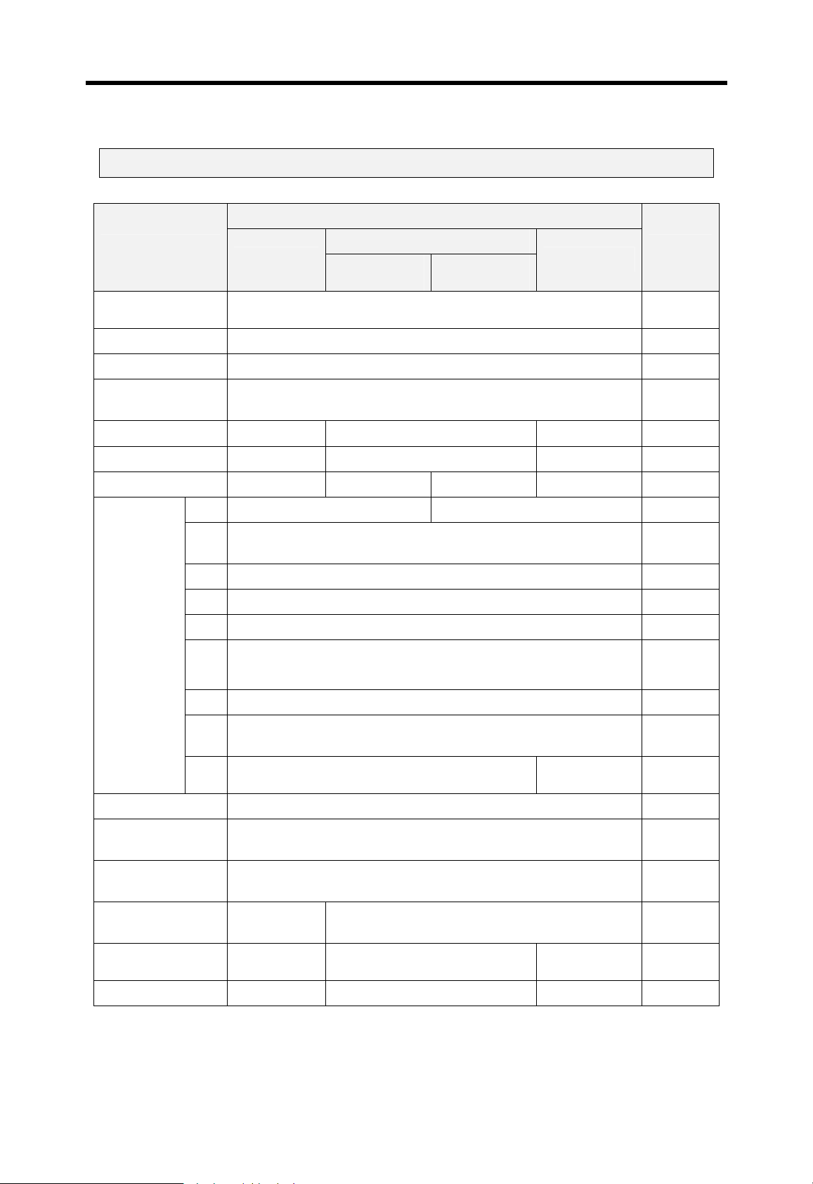
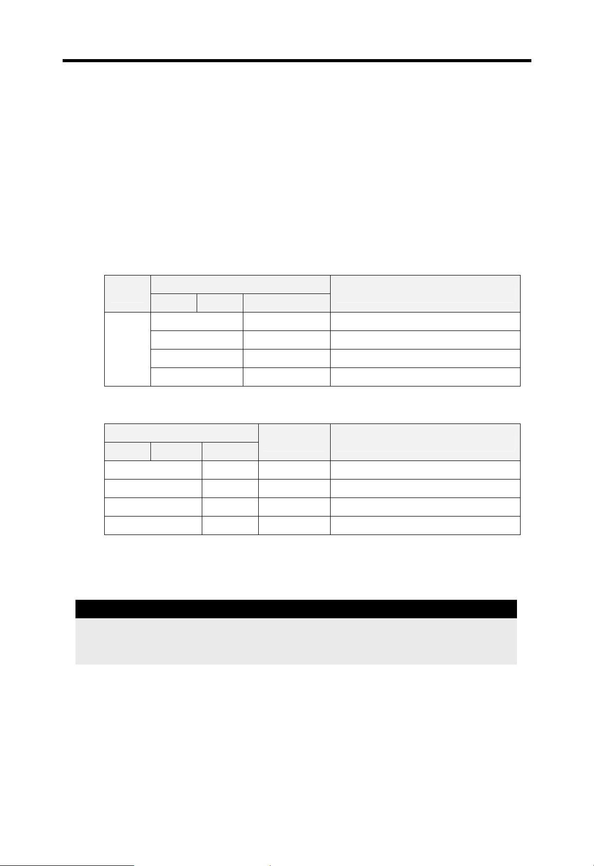
This user’s manual contains specifications, performance, and handling instructions for each of
unit of MASTER-K 200S/300S/1000S series PLC system.
The following table shows the configuration of this user’s manual.
Chapter Item Description
1 Instruction
2 System configuration
3 Specifications
4 CPU module
5 Battery
6 Memory module
7 Digital I/O module
8 Power supply module
9 Base and cable
10 Installation and wiring
11 Maintenance
12 Troubleshooting
Describes configuration of this manual, modules
features and terminology.
Describes available modules and system
configurations in the MASTER-K200S/300S/1000S
series.
Describes general specifications of various modules
used in the MASTER-K200S/300S/1000S series.
Describes the performance, specifications and
functions of the CPU module.
Describes the specifications and handling instructions
for other modules except for the CPU module.
Describes installation, wiring and handling instructions
for reliability of the PLC system.
Describes the check point and method for
maintenance of the PLC system.
Describes various operation errors and corrective
actions.
13
14
15 PID function of K200S
16
Appendix 1 Flag list Describes types and contents of various flags
Appendix 2 Dimension
Remark
In this manual, it is not described that the hardware information and programming of
special/communication modules. Please refer the user’s manual of each module for details.
RS232C communication
for K200S
RS422 communication
for K200S
High speed counter of
K200S
Describes the RS-232C communication function of
K200S A and C type
Describes the RS422 communication functions of
K200S B type
Describes the PID control function of K200S B and C
type
Describes the HSC function of K200S C type
Shows dimensions of CPU, I/O modules and base
unit
1-1

Chapter 1 Instruction MASTER-K
1.2 Features
The features of MASTER-K 200S/300S/1000S series are as following;
1) Program compatibility with previous MASTER-K series
2) Support various and easy-to-use programming devices
① KGL-WIN : Graphic loader for Windows 95 / 98
② KLD-150S : Hand-held loader
3) Open network by supporting communication protocol complying with international
standard.
4) Fast processing speed (operation dedicated processor is mounted)
① K200S : 0.5 μsec / step
② K300S / K1000S : 0.2 μsec / step
5) Various special modules that enlarge the application range of PLC
6) Enhanced self-diagnosis functions
The MASTER-K 200S/300S/1000S series provides more detail error codes that make the
cause of error can be found more easily.
7) Debug function
On-line debugging is available by changing the operation mode as RUN Æ Debug. The
MASTER-K 200S/300S/1000S series provides following debugging functions;
① Execution by one instruction
② Execution by break point setting
③ Execution by the device status
④ Execution by specified scan times
8) Various program types
The MASTER-K 200S/300S/1000S series supports various program types such as timedriven interrupt (TDI), process-driven interrupt (PDI), and subroutine program.
1-2

Chapter 1 Instruction MASTER-K
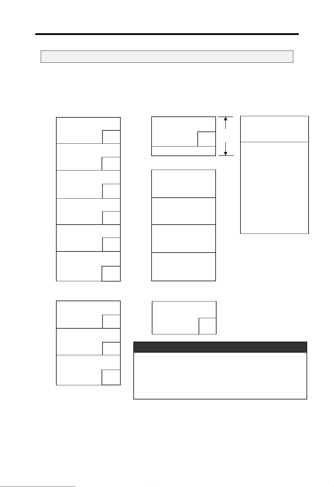
1.3 Terminology
The following table shows the definition of terms used in this manual.
Terms Definition Remark
A standard element that has a specified function which
Module
Unit
PLC system
KGL-WIN
KLD-150S
I/O image area
FAM
Fnet Fieldbus network
Cnet Computer network (RS-232C, RS-422/485)
configures a system. Devices such as CPU or I/O, which
mounted on the base board or base unit.
A single mod ule or group of modules that performs an
independent operation as a part of PLC system.
A system that con sists of PLC and peripheral devices that
are controlled by user program.
A computer software for Windows 95 / 98 used for write,
editing, and debugging of user program of MASTER-K
series.
A hand-held loader used for write, editing, and debugging
of user program of MASTER- K series
Internal memory area of CPU module that holds the I/O
status during PLC operation.
Abbreviation of the ‘Factory Automation Monitoring S/W’. It
is used to call software for process supervisio n.
Example)
CPU module,
Power module,
I/O module, etc.
Example)
main unit,
expansion unit
Pnet ProfiBus Network
Enet Ethernet Network
RTC
Watchdog timer
Abbreviation of ‘Real Time Clo ck’. It is used to call general
ICs that contains clock function.
An internal timer used for supervising program execution
time. It gives a warning when the execution time exceeds
the preset time.
1-3
Chapter 1 Instruction MASTER-K
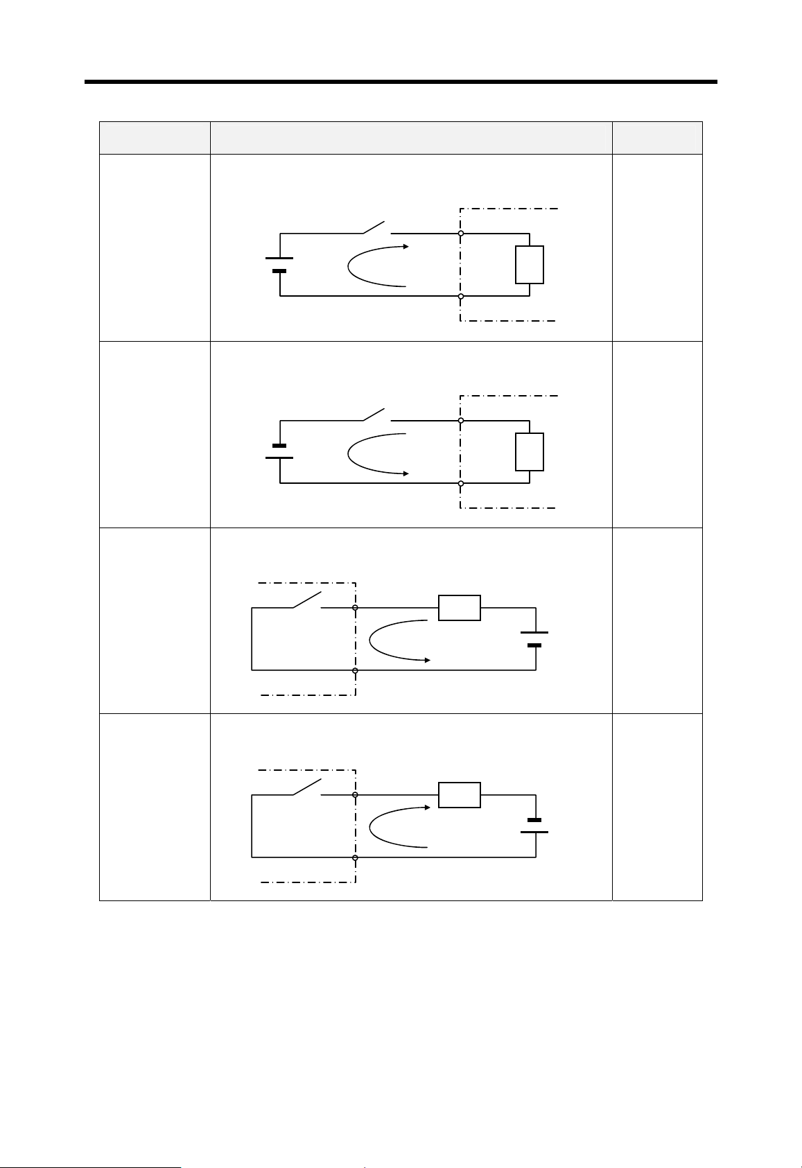
y
y
Terms Definition Remark
Current flows in from the input switch to the input terminal of
PLC when an input signal is turned on.
PLC
Z: Input
Z
impedance
Sink input
Switch
+
Power
Current
Input
terminal
Source input
Sink output
Common
Current flows out from the input terminal of PLC to the input
switch when an input signal is turned on.
Switch
–
Power
+
Current
Input
terminal
Common
PLC
Z
Current flows in from the external load to the output terminal of
PLC when an output signal is turned on.
PLC
Output
rela
Output
terminal
Common
Z
+
Power
Current
Source output
Current flows out from the output terminal of PLC to the
external load when an output signal is turned on.
PLC
Output
rela
Output
terminal
Common
Current
Z
–
Power
+
1-4

Chapter 2 System configuration
2 System configuration ...........................................................................................2-1
2.1 Overall configuration................................................................................................2-1
2.1.1 K200S series..........................................................................................................2-1
2.1.2 K300S / 1000S series............................................................................................2-2
2.2 Product list................................................................................................................2-3
2.2.1 K200S.................................................................................................................... 2-3
2.2.2 K300S.................................................................................................................... 2-5
2.2.3 K1000S.................................................................................................................. 2-8
2.3 System configuration types................................................................................... 2-11
2.3.1 Basic system configuration.................................................................................. 2-11
2.3.2 Computer link system..........................................................................................2-12
2.3.3 Network system...................................................................................................2-13

Chapter 2 System configuration MASTER-K
2 System configuration
The MASTER-K 200S/300S/1000S series has various modules suitable to configuration from
the basic to a large network system. This chapter describes the configuration and features of
each systems.
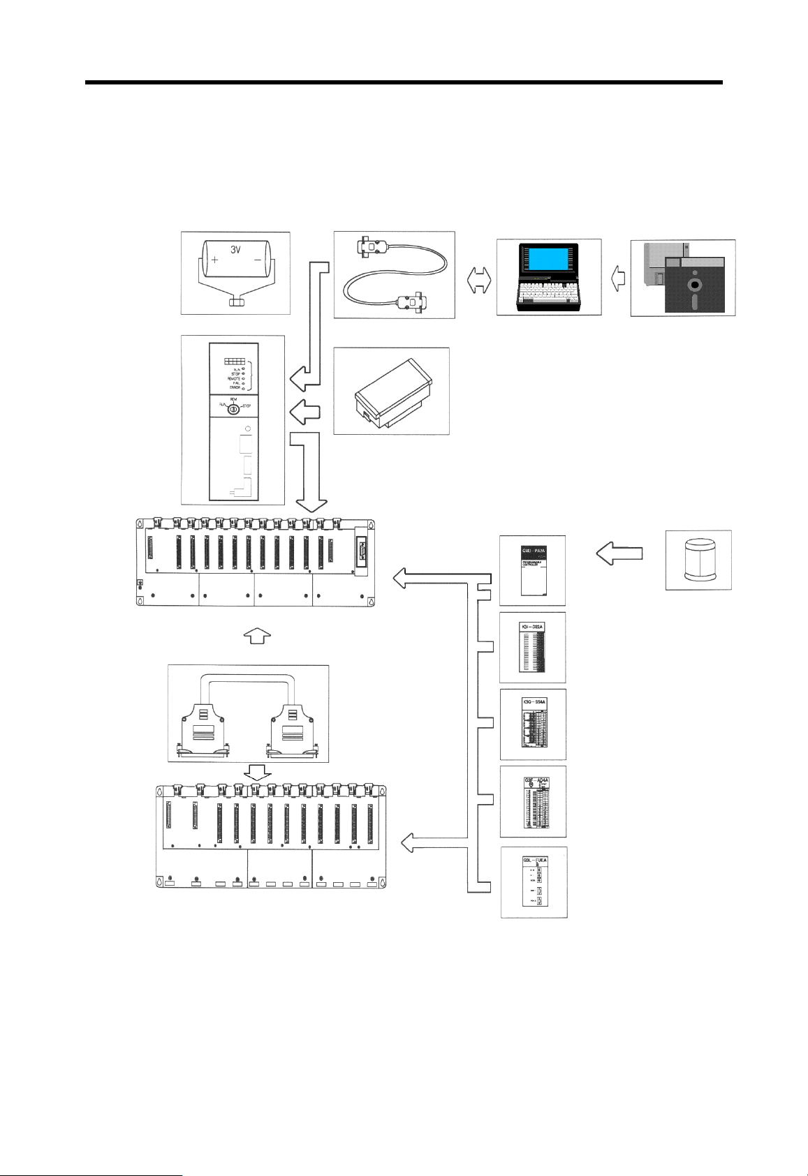
2.1 Overall configuration
2.1.1 K200S series
The overall system configuration of K200S series is as following;
Battery
POWER O
K3S-301S
Power Supply
Module
(K3S-□□□S)
K3P-07AS
RUN
PAU/RE
M
CPU Module
KGL-WIN
RS-232C
Cable
IBM
compatible PC
Base board(GM6 – B □□M)
KGL-WIN S/W
G6I-D22A
G6Q-RY2A
G6F-AD2A
G6L-FUEA
(G6I-□□□S)
Input Module
Output Module
(G6Q-□□□S)
Special Module
(G6F-□□□□)
Communication
Module
(G6L-□□□□)
2-1
Chapter 2 System configuration MASTER-K
2.1.2 K300S / 1000S series
The overall system configuration of K300S/1000S series is as following;
CPU Module
Battery
-
Main Base
Memory Module
IBM compatible PC RS232-C Cable
MASTER-K
Power Supply
Module
Input Module
KGL-WIN
Fuse
Expansion Cable
Expansion Base
Output Module
Special Function Module
Communication Module
2-2

Chapter 2 System configuration MASTER-K
2.2 Product list
The product list of K200S/300S/1000S are as following;
2.2.1 K200S
Items Model No. Description Remark
Max. I/O points : 512 points
Special functions : RS-232C
Max. I/O points : 512 points
Special functions : RS-422/485, RTC, PID control
Max. I/O points : 512 points
Special functions : RS-232C, RTC, HSC, PID control
12/24VDC input, 8 points (source/sink)
Relay output, 8 points, 2A/point
100 ~
240VAC
5VDC (3.5A), 24VDC (0.3A)
12 ~
24VDC
5VDC (3A), +15VDC (0.5A), -15VDC (0.2A)
CPU
modules
Digital
input
modules
Digital
output
modules
Digital I/O
hybrid
module
Main
bases
Power
supply
modules
K3P-07AS
K3P-07BS
K3P-07CS
G6I-D21A 12/24VDC input, 8 points (source/sink)
G6I-D22A 12/24VDC input, 16 points (source/sink)
G6I-D22B 24VDC input, 16 points (source)
G6I-D24A 12/24VDC input, 32 points (source/sink)
G6I-D24B 24VDC input, 32 points (source)
G6I-A11A 110VAC input, 8 points
G6I-A21A 220VAC input, 8 points
G6Q-RY1A Relay output, 8 points, 2A/point 1points/com
G6Q-RY2A Relay output, 16 points, 2A/point
G6Q-TR2A Transistor output, 16 points, 0.5A/point (sink)
G6Q-TR2B Transistor output, 16 points, 0.5A/point (source)
G6Q-TR4A Transistor output, 32 points, 0.1A/point (sink)
G6Q-TR4B Transistor output, 32 points, 0.1A/point (source)
G6Q-SS1A Triac output, 16 points, 1A/point
G6H-DR2A
GM6-B04M 4 module
GM6-B06M 6 module
GM6-B08M 8 module
GM6-B12M 12 module
GM6-PAFA 5VDC (2A), 24VDC (0.3A)
GM6-PAFB 5VDC (2A), +15VDC (0.5A), -15VDC (0.2A)
GM6-PAFC
GM6-PDFA 5VDC (2A)
GM6-PDFB
2-3

Chapter 2 System configuration MASTER-K
(continued)
Items Model No. Description Remark
A/D conversion
modules
D/A conversion
modules
High speed
counter module
Special modules
Positioning
module
Thermocouple
module
Fnet modules
Cnet modules
DeviceNet
module
ProfiBus module
Network modules
Dust-cover GM6-DMMA Dust-protector for unused slot
G6F-AD2A
G6F-DA2V
G6F-DA2I
G6F-HSCA
G6F-POPA Pulse output, 2 axes control
G6F-TC2A
G6L-FUEA
G6L-RBEA
G6L-CU2A Cnet I/F module (RS-232C)
G6L-CU4A Cnet I/F module (RS-422/485)
G6L-DUEA DeviceNet I/F module
G6L-PUEA ProfiBus I/F module
G6L-PUEB ProfiBus I/F module
Voltage / Current input, 4channels
1 ~ 5VDC / 0 ~ 10VDC / -10 ~ 10VDC
DC 4 ~ 20mA
Voltage output, 4 channels
-10 ~ 10VDC
Current output, 4 channels
DC 4 ~ 20mA
Counting range ( 0 ~ 16,777,215 : binary 24 bits)
50kHz, 1 channel
Sensor type : 7 types (K, J, E, T, B, R, S)
Input channel : 4 channels
Fnet I/F module
1Mbps base band, Twisted pair cable
Fnet remote I/F module
1Mbps base band, Twisted pair cable
2-4

Chapter 2 System configuration MASTER-K
2.2.2 K300S
Items Model No. Description Remark
CPU
modules
Digital
input
modules
Digital
output
modules
Main base
boards
Expansion
base
boards
Expansion
cables
K4P-15AS Max. I/O points : 512 points
G4I-D22A 12/24VDC input, 16 points (source/sink)
G4I-D22B 12/24VDC input, 16 points (source)
G4I-D22C 24VDC input, 16 points (source/sink)
G4I-D24A 12/24VDC input, 32 points (source/sink)
G4I-D24B 12/24VDC input, 32 points (source)
G4I-D24C 24VDC input, 32 points (source/sink)
G4I-D28A 12/24VDC input, 64 points (source/sink)
G4I-A12A 110VAC input, 16 points
G4I-A22A 220VAC input, 16 points
G4Q-RY2A Relay output, 16 points, 2A/point
G4Q-TR2A Transistor output, 16 points, 0.5A/point (sink)
G4Q-TR2B Transistor output, 16 points, 0.5A/point (source)
G4Q-TR4A Transistor output, 32 points, 0.1A/point (sink)
G4Q-TR4B Transistor output, 32 points, 0.1A/point (source)
G4Q-TR8A Transistor output, 64 points, 0.1A/point (sink)
G4Q-SS2A Triac output, 16 points, 1A/point
G4Q-SS2B Triac output, 16 points, 0.6A/point
GM4-B04M 4 module
GM4-B06M 6 module
GM4-B08M 8 module
GM4-B12M 12 modules No expansion
GM4-B04E 4 modules
GM4-B06E 6 modules
GM4-B08E 8 modules
G4C-E041 Length : 0.4m
G4C-E121 Length : 1.2m
G4C-E301 Length : 3.0m
Memory
module
Power
supply
modules
GM4-M032 Flash memory, 32k steps
GM4-PA1A 110VAC
GM4-PA2A 220VAC
GM4-PA1B 110VAC
GM4-PA2B 220VAC
GM4-PD3A 24VDC
5VDC : 5A, 24VDC : 0.7A
5VDC : 3A, 24VDC : 0.5A,
5VDC : 4A, 24VDC : bypass
2-5

Chapter 2 System configuration MASTER-K
(continued)
Items Model No. Description Remark
Voltage / Current input, 4channels
-5 ~ 5VDC / -10 ~ 10VDC
DC -20 ~ 20mA
Voltage / Current input, 8channels
1 ~ 5VDC / 0 ~ 10VDC
DC 4 ~ 20mA
Voltage / Current output, 2 channels
-10 ~ 10VDC, DC4 ~ 20mA
Voltage output, 4 channels
-10 ~ 10VDC
Current output, 4 channels
DC 4 ~ 20mA
Voltage output, 8 channels
-10 ~ 10VDC
Current output, 8 channels
DC 4 ~ 20mA
A/D
conversion
modules
D/A
conversion
modules
G4F-AD2A
G4F-AD3A
G4F-DA1A
G4F-DA2V
G4F-DA2I
G4F-DA3V
G4F-DA3I
High
speed
counter
module
Special modules
Positioning
module
Thermoco
uple input
module
RTD
module
PID control
module
Analog
timer
module
Interrupt
module
G4F-HSCA
G4F-POPA Pulse output, 1 axis control
G4F-POPB Pulse output, 2 axes control
G4F-TC2A
G4F-RD2A
G4F-PIDA Max. 8 loops control
G4F-AT3A
G4F-INTA 8 channels
Counting range ( 0 ~ 16,777,215 : binary 24 bits)
50kHz, 1 channel
Sensor type : 7 types (K, J, E, T, B, R, S)
4 channels
Sensor type : Pt100, JPt100
4 channels
8 analog timers
Setting range : 0.1 ~ 1.0sec / 1 ~ 10sec
10 ~ 60sec / 60 ~ 600sec
Each channel
can be set
independently
2-6

Chapter 2 System configuration MASTER-K
(continued)
Items Model No. Description Remark
Fnet I/F module
1Mbps base band, Twisted pair cable
Fnet I/F module
1Mbps base band, Twisted pair cable
Fnet remote I/F module
1Mbps base band, Twisted pair cable
Fnet single I/F module
12 / 24VDC input, 16 points
Fnet single I/F module
Relay output, 1A/point, 16 points
Fnet single I/F module
12 / 24VDC input, 8 points
Relay output, 1A/point, 16 points
Install to the IBM
compatible PC
Fnet
modules
G4L-FUEA
G0L-FUEA
G4L-RBEA
G0L-SMIA
G0L-SMQA
G0L-SMHA
G0L-FREA Repe ater for Fnet
Converter
Network modules
Active
coupler
Cnet
modules
DeviceNet I/F
module
Profibus-DP
I/F module
Pseudo
input
switch
Others
Dust cover
G0L-FOEA
G0L-FAPA Power module for active coupler
G0L-FABA Base board for active coupler
G0L-FACA Active coupler
G0L-FADA Dummy card for active coupler
G4L-CUEA Cnet I/F module (RS-232C)
G4L-DUEA
Optical ↔ Electrical converter
DeviceNet I/F module
G4L-PUEA Profibus-DP master module (I/O : 1K)
G4L-PUEB
G4S-SW16 Pseudo input switch, 16 po ints
GM4-DMMA Dust protector for unused slot
Profibus-DP master module (I/O : 7K)
In 3.0 or higher
CPU O/S version
and 3.2 or higher
KGL-WIN version
2-7

Chapter 2 System configuration MASTER-K
2.2.3 K1000S
Items Model No. Description Remark
CPU
modules
Digital
input
modules
Digital
output
modules
Main base
boards
Expansion
base
boards
Expansion
cables
K7P-30AS Max. I/O points : 1,024 points
G3I-D22A 12/24VDC input, 16 points (source/sink)
G3I-D24A 12/24VDC input, 32 points (source/sink)
G3I-D24C 24VDC input, 32 points (source/sink)
G3I-D28A 12/24VDC input, 64 points (source/sink)
G3I-A12A 110VAC input, 16 points
G3I-A22A 220VAC input, 16 points
G3I-A14A 110VAC input, 32 points
G3I-A24A 220VAC input, 32 points
G3Q-RY2A Relay output, 16 points, 2A/point
G3Q-RY4A Relay output, 32 points, 1A/point
G3Q-TR2A Transistor output, 16 points, 2A/point (sink)
G3Q-TR4A Transistor output, 32 points, 0.5A/point (sink)
G3Q-TR4B Transistor output, 32 points, 0.5A/point (source)
G3Q-TR8A Transistor output, 64 points, 0.1A/point (sink)
G3Q-TR8B Transistor output, 64 points, 0.1A/point (source)
G3Q-SS2A Triac output, 16 points, 2A/point
G3Q-SS4A Triac output, 32 points, 1A/point
GM3-B04M 4 module
GM3-B06M 6 module
GM3-B08M 8 module
GM3-B04E 4 modules
GM3-B06E 6 modules
GM3-B08E 8 modules
G3C-E061 Length : 0.6m
G3C-E121 Length : 1.2m
G3C-E301 Length : 3.0m
Memory
module
Power
supply
modules
G3M-M064 Flash memory, 64k steps
GM3-PA1A 110VAC
GM3-PA2A 220VAC
GM1-PA1A 110VAC
GM1-PA2A 220VAC
GM3-PD3A 24VDC
5VDC : 7A, 24VDC : 1.5A
5VDC : 13A, 24VDC : None
5VDC : 4A, 24VDC : bypass
2-8

Chapter 2 System configuration MASTER-K
(continued)
Items Model No. Description Remark
Voltage / Current input, 16 channels
-5 ~ 5VDC / -10 ~ 10VDC
DC -20 ~ 20mA
Voltage / Current input, 16 channels
1 ~ 5VDC / 0 ~ 10VDC
DC 4 ~ 20mA
Voltage / Current input, 8 channels
1 ~ 5VDC / 0 ~ 10VDC
DC 4 ~ 20mA
Voltage output, 16 channels
-5 ~ 5VDC / -10 ~ 10VDC
Current output, 16 channels
DC 4 ~ 20mA
Voltage output, 8 channels
0 ~ 10VDC
Current output, 8 channels
DC 4 ~ 20mA
+15VDC : 0.5A
-15VDC : 0.1A
Counting range ( 0 ~ 16,777,215 : binary 24 bits)
50kHz, 2 channels
Sensor type : 7 types (K, J, E, T, B, R, S)
16 channels
Sensor type : Pt100, JPt100
8 channels
16 analog timers
Setting range : 0.1 ~ 1.0sec / 1 ~ 10sec
10 ~ 60sec / 60 ~ 600sec
For A/D & D/A
modules
Each channel
can be set
independently
A/D
conversion
modules
D/A
conversion
modules
Power
supply
module
High speed
counter
module
Positioning
module
Thermocou
ple input
module
RTD
module
PID control
module
Analog
timer
module
Interrupt
module
G3F-AD4A
G3F-AD4B
G3F-AD3A
G3F-DV4A
G3F-DI4A
G3F-DV3A
G3F-DI3A
G3F-PA1A 110VAC
G3F-PA2A 220VAC
G3F-HSCA
G3F-POPA Pulse output, 1 axis control
G3F-POAA Analog output, 2 axes control
G3F-TC4A
G3F-RD3A
G3F-PIDA Max. 32 loops control
G3F-AT4A
G3F-INTA 16 channels
2-9

Chapter 2 System configuration MASTER-K
(continued)
Items Model No. Description Remark
Fnet I/F module
1Mbps base band, Twisted pair cable
Fnet I/F module
1Mbps base band, Optical fiber cable
Fnet I/F module
1Mbps base band, Twisted pair cable
Fnet remote I/F module
1Mbps base band, Twisted pair cable
Fnet remote I/F module
1Mbps base band, Optical fiber cable
Fnet single I/F module
12 / 24VDC input, 16 points
Fnet single I/F module
Relay output, 1A/point, 16 points
Fnet single I/F module
12 / 24VDC input, 8 points
Relay output, 1A/point, 16 points
Install to the IBM
compatible PC
Fnet
modules
Network modules
G3L-FUEA
G3L-FUOA
G0L-FUEA
G3L-RBEA
G3L-RBOA
G0L-SMIA
G0L-SMQA
G0L-SMHA
G0L-FREA Repe ater for Fnet
Converter
Active
coupler
Cnet
modules
Profibus-DP
I/F module
Pseudo
input
switch
Others
Dust cover
G0L-FOEA
G0L-FAPA Power module for active coupler
G0L-FABA Base board for active coupler
G0L-FACA Active coupler
G0L-FADA Dummy card for active coupler
G3L-CUEA Cnet I/F module (RS-232C:1ch / RS422:1ch)
Optical ↔ Electrical converter
G3L-PUEA Profibus-DP master module (I/O : 1K)
G3L-PUEB
G3S-SW32 Pseudo input switch, 32 po ints
G3F-DMMA Dust protector for unused slot
Profibus-DP master module (I/O : 7K)
In 3.0 or higher
CPU O/S version
and 3.2 or higher
KGL-WIN version
2-10

Chapter 2 System configuration MASTER-K
2.3 System configuration types
System configuration is classified into 3 types such as basic, computer link, and network system.
2.3.1 Basic system configuration
The basic system consists of a main base and expansion base(s). The main and expansion
base(s) are connected via expansion cable.
Main base
Expansion
base
Power
CPU
Power
Slot 0
Slot 0
Slot 1
Slot 2
Slot 3
Slot 4
Slot 5
Slot 6
Slot 7
Expansion
cable
Slot 1
Slot 2
Slot 3
Slot 4
Slot 5
Slot 6
Slot 7
Max. expansion level – 3 levels
Max. distance between bases – 3 m
Max. numbers of I/O module 12 modules 32 modules
Max. I/O points 384 points 512/1,024 points1 1,024 points
CPU K3P-07AS K4P-15AS K7P-30AS
Power supply
Module
type
Main base
Expansion base – GM4-B04/06/08E GM3-B04/06/08E
Expansion cable – G4C-E041/121/301 G3C-E061/121/301
I/O module
Special-function
module
K200S K300S K1000S
GM6-PAFA/B/C
GM6-PDFA/B
GM6B04/06/08/12M
G6I-
G6Q-
G6F-
GM4-PA1A/PA2A
GM4-PA1B/PA2B
GM4-PD3A
GM4-
B04/06/08/12M
G4I-
G4Q-
G4F-
GM3-PA1A/PA2A
GM3-PA1B/PA2B
GM3-PD3A
GM3-B04/06/08M
G3I-
G3Q-
G3F-
I/O number (P00, P01, …) is allocated for each module
I/O number allocation
1
Only in 3.0 or higher CPU O/S version
automatically. A empty slot occupies 16 bits.
Special-functi on modules can be mounted on all bases and
slots with no limit on the number of modules.
2-11

Chapter 2 System configuration MASTER-K
2.3.2 Computer link system
When a CPU module is connected with external devices (such as computer or printer, etc.)
via RS-232C or RS-422/485 protocol by using computer link module, it is called as computer
link system. For details about computer link system, please refer user’s manual of MK
computer link modules.
Remark
The maximum number of Cnet modules that can be mounted simultaneously is as following;
K200S : 2 modules K300S : 4 modules K1000S : 8 modules
Cnet modules can be mounted only main base board. (Not available for expansion base board)
In 3.0 or higher CPU O/S version, Cnet module can be mounted on a main or expansion base
board-
2-12

Chapter 2 System configuration MASTER-K
2.3.3 Network system
In network system, user can access and control I/O module of remote station through a
network I/F and remote I/F module. MASTER-K series uses the Fnet system to consist a
network system.
Besides, in 3.0 or higher CPU O/S version and in 3.2 or higher KGL-WIN version, user who want
to use other network system can use the Dnet I/F sy stem or
system. (Dnet I/F syst em or
Profibus I/F system is available for K300S and Profibus I/F system is
Profibus I/F to construct a network
available for K1000S)
Please refer the user’s manual of Fnet network module for details.
Remark
1. Fnet network module can be mounted on main a base board only. It can not be mounted on a
expansion base board
The maximum number of Fnet modules that can be mounted simultaneously is as following;
K300S: 2 modules K1000S : 4 modules
2. In 3.0 or higher K300S/1000S CPU O/S version , high-speed link communication module can
be mounted on a main or expansion base board and the maximum number that can be
mounted simultaneously is 4
3. The remote system has same configuration with a basic system configuration. However, the
following modules can not be used on the remote system which a Fnet remote I/F module is
mounted.
PID control module G4F-PIDA G3F-PIDA
Positioning module G4F-POPA G3F-POPA
G4F-POPB G3F-POAA
Analog timer module G4F-AT3A G3F-AT4A
Fnet I/F module G4L-FUEA G3L-FUEA
Cnet I/F module G4L-CUEA G3L-CUEA
Example) K300S Network system
GM4-PA2A
Fnet I/F module
G4L-FUEA
K4P-15AS
Fnet remote
I/F module
GM4-PA1A
The above modules can not
be mounted on these slots
K4F-RBEA
Main base
2-13

Chapter 3 General specifications
3 General specifications.............................................................................. 3-1
Chapter 3 General specifications MASTER-K
3 General specifications
The following table shows the general specifications of MASTER-K series.
No Item Specifications Remark
Operating ambient
1
temperature
Storage ambient
2
temperature
Operating ambient
3
4
5 Vibration resistance
6 Shock resistance
7 Noise immunity
8 Atmosphere Free of corros ive gases
9 Altitude for use Up to 2,000m ( 6,560ft )
10 Pollution degree 2
11 Cooling method Self-cooling
humidity
Storage ambient
humidity
0 ~ 55℃ (32 ~ 131 °F)
-25 ~ 70℃ (-13 ~ 158 °F)
5 ~ 95%RH, non-condensing
5 ~ 95%RH, non-condensing
Occasional vibration
Frequency Acceleration Amplitude Sweep count
10≤f<57 Hz - 0.075 mm
57 ≤f≤150 Hz 9.8 ㎨ (1G) -
Continuos vibration
Frequency Acceleration Amplitude
10≤f<57 Hz - 0.035 mm
57≤f≤150 Hz 4.9㎨ (0.5G) -
Maximum shock acceleration: 147 ㎨ (15G)
Duration time :11 ms (3 times in each of X, Y and Z directions)
Pulse wave: half sine wave pulse
Square wave
impulse noise
Electrostatic
discharge
Radiated electro-
magnetic field
Fast transient
burst noise
±1,500 V
Voltage :4 kV(contact discharge)
27 ~ 500 MHz, 10 V/m
Severity
Level
Voltage 2 kV 1 kV 0.25 kV
All power
modules
Digital I/O
( Ue ≥ 24 V)
10 times in each
direction for X, Y, Z
10 times in each
direction for X, Y, Z
Digital I/O (Ue<24 V)
Analog I/O
Communication I/O
IEC 1131-2
IEC 1131-2
LGIS ’ s
specification
IEC 1131-2
IEC 801-2
IEC 1131-2
IEC 801-2
IEC 1131-2
IEC 801-4
Remark
1. IEC (International Electrotechnical Commission) : The international civilian organization which
produces standards for electrical and el ectronics industry.
2. Pollution degree : It indicates a standard of operation ambient pollution level. The pollution
degree 2 means the condition in which normally, only non-conductive pollution occurs.
Occasionally, however, a temporary conductivity caused by condensation shall be expected.
3-1

Chapter 4 CPU modules
4 CPU modules............................................................................................. 4-1
4.1 Performance specifications.....................................................................................4-1
4.2 Operation processing of CPU.................................................................................. 4-2
4.2.1 Operation method..................................................................................................4-2
4.2.2 The operation during momentary power failure.....................................................4-3
4.2.3 Scan time...............................................................................................................4-4
4.2.4 Watchdog timer...................................................................................................... 4-4
4.2.5 Timers .................................................................................................................... 4-5
4.2.6 Counter.................................................................................................................. 4-8
4.3 Program structure...................................................................................................4-10
4.3.1 Classification of program.....................................................................................4-10
4.3.2 Processing method..............................................................................................4-10
4.3.3 Interrupt processing............................................................................................. 4-11
4.3.4 Error handling......................................................................................................4-15
4.4 Operation mode ...................................................................................................... 4-16
4.4.1 RUN mode........................................................................................................... 4-16
4.4.2 Stop mode............................................................................................................4-17
4.4.3 PAUSE mode....................................................................................................... 4-18
4.4.4 DEBUG mode...................................................................................................... 4-19
4.4.5 Operation mode change...................................................................................... 4-20
4.5 Special functions of CPU module ......................................................................... 4-22
4.5.1
RTC (Real Time Clock) function .......................................................................... 4-22
4.5.2 Forced I/O setting................................................................................................4-25
4.5.3 Program edit in RUN mode..................................................................................4-26
4.5.4 Self-diagnosis......................................................................................................4-27
4.5.5 Direct I/O refresh..................................................................................................4-28
4.5.6 System error history.............................................................................................4-28
4.6 Memory configuration............................................................................................ 4-29
4.6.1 Memory map of K200S / K300S.......................................................................... 4-29
4.6.2 The memory map of K1000S...............................................................................4-30
4.7 Assign I/O address ................................................................................................. 4-31
4.8 Parts names............................................................................................................. 4-32
Chapter 4 CPU modules MASTER-K
4 CPU modules
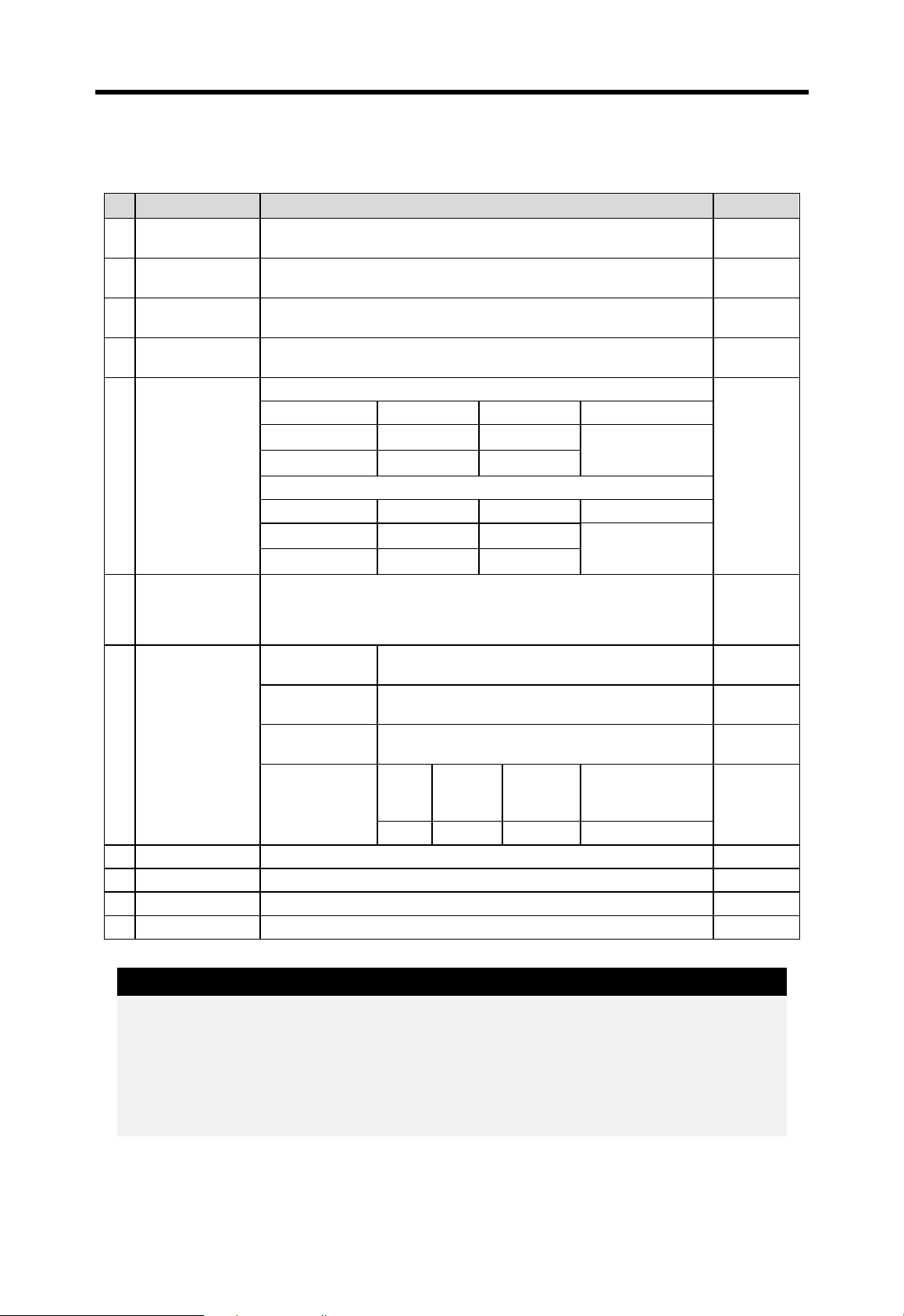
4.1 Performance specifications
The performance specification of K200S / 300S / 1000S series is shown as following table;
Specifications
Item
Program control
method
I/O control method Indirect mode (Refresh method), Direct by program command
Program language Mnemonic, Ladder diagram
Numbers of
instructions
Processing speed
Program capacity 7k steps 15k steps 30k steps
Max. I/O points 384 points 512 points 1,024 points 1,024 points
P P000 ~ P31F (512 points) P000 ~ P63F (1,024 points) I/O relay
M M000 ~ M191F (3,072points)
K K000 ~ K31F (512 points) Keep relay
L L000 ~ L63F (1,024 points) Link relay
Memory
device
F F000 ~ F63F (1,024 points) Special relay
T
K200S
Cycle execution of stored program, Time-driven interrupt,
0.5μsec/step 0.2μsec/step 0.2μsec/step
2.X or lower
CPU O/S version
Process-driven interrupt
Basic : 30, Application : 218
100ms : T000 ~ T191 (192 points)
10ms : T192 ~ T255 (64 points)
K300S
3.X or higher
CPU O/S version
K1000S
Remarks
Auxiliary
relay
Timer
C C000 ~ C255 (256 point s) Counter
S
D D0000 ~ D4999 (5,000 words)
Operation modes RUN, STOP, PAUSE, DEBUG
Self-diagnosis
functions
Data back-up
method
Max. expansion
level
Current
consumption
Weight 0.11kg 0.25kg 0.42kg
Detect errors of scan time, memory, I/O, battery, and power supply
None Up to 3 level
170mA (A type)
210mA (B/C type)
S00.00 ~ S99.99 (100×100 steps)
D0000 ~ D9999
(10,000 words)
Battery-back-up
130mA 130mA
4-1
Step
controller
Data
register

Chapter 4 CPU modules MASTER-K
4.2 Operation processing of CPU
4.2.1 Operation method
1) The repetitive operation
The repetitive operation method repeats execution of a series of operations. The CPU
repeats the operation processing as following;
Step Description
Start of opera t ion
Initializing operation
Refresh input image data
Program execution
0 step
The preparation step to execute scan operation
Executed only 1 time when power is turned on or
CPU is reset.
The following operation is executed;
- I/O module reset
- Self-diagnosis operation
- Clear non-retentive data
- Read I/O information and assign address
Before start of scan operation, read the status of
input module and store it to the input image data
area.
Execute the user program from step 0 to the last
step
Last step
After the last step is executed, output the operation
Refresh output image data
Execute END operation
result of output image data area to the output
module
Before restart scan operation, the following
operation is executed;
- Self-diagnosis operation
- Update the current value of timer and counter
- Execute data transmission with network module
- Check the operation mode is changed or not
4-2

Chapter 4 CPU modules MASTER-K
2) Interrupt operation
When the CPU detects an interrupt signal, it stops the current operation and execute the
corresponding interrupt routine. After the interrupt routine is completed, the CPU resumes
to execute the previous operation from the stopped point.
The MASTER-K 200S/300S/1000S has two interrupt types that are time-driven interrupt
(TDI) and process-driven interrupt (PDI). Please refer the chapter 4.3.3 for detail s.
4.2.2 The operation during momentary power failure
The MASTER-K 200S/300S/1000S series can detect a momentary power failure, and the
CPU module decides to continue operation or not according to the period of momentary
power failure.
1) Less than 20msec
① The CPU stop to execute sequence program
2) Over 20msec
Less than 20ms
Over 20ms
retaining the state of output.
② The time measurement for internal timer and
time-driven interrupt keeps normal operation
status while the sequence program is
stopped.
③ When the AC power is recovered, the CPU
restarts to execute sequence prog ram.
④ The external output of power supply module
is kept as the rated voltage and current.
The CPU will initialized and restart operation
as the power re-applied.
Remark
Momentary power failure:
The power failure of PLC system means the state that AC input voltage is dropped below the
minimum value of rated input voltage range. When the period of power failure is short (usually,
the 1/2 cycle), it is called as momentary power failure.
4-3

Chapter 4 CPU modules MASTER-K
4.2.3 Scan time
The series of steps from step 0 to the next step 0 or from an END instruction to the next
END instruction is called a scan. The scan time is total time spent to execute a scan.
1) The calculation of scan time
The scan time is calculated as a total of the processing time of sequence program (step 0
to the END), interrupt routine, and internal processing of CPU.
Scan time = Sequence program processing time + Interrupt routine processing time
+ Internal processing time
① Sequence program processing time :
The total processing time to execute step 0 to END instruction
② Interrupt processing time :
The total processing time to execute interrupt routine during a scan
③ Internal processing time :
The total processing time to execute self-diagnosis, I/O refresh, timer/counter update,
and communication operation
2) The scan time varies with executing interrupt routine and communication operation or not.
3) The scan time of CPU module is stored in the following special relays (F area).
- F50 word : The maximum scan time (unit : ms)
- F51 word : The minimum scan time (unit : ms)
- F52 word : The current scan time (unit : ms)
4.2.4 Watchdog timer
1) The watchdog timer is an internal timer of the CPU to detect the error of hardware and
sequence program. The default value of watchdog timer is 200msec, and it can be
changed in parameter setting. (setting range : 10 ~ 6000msec, unit : 10msec)
2) When a scan is not completed before, the watchdog timer error occurs and the operation
of CPU is stopped. At this time, all outputs of I/O module are turned off.
3) The watchdog timer is reset before step 0 is executed (after the END processing is
finished) or the WDT instruction is executed. When write a sequence program contains
FOR ~ NEXT loop or a lot of subroutines, increase watchdog timer setting value or put
WDT instruction to avoid watchdog timer error. The setting range of watchdog timer is 10
~ 6000msec
4) When a watchdog timer error occurs, it can be cleared by power cycle, manual reset
switch (K1000S), or mode change.
4-4

Chapter 4 CPU modules MASTER-K
(PV)
4.2.5 Timers
The MASTER-K 200S/300S/1000S series uses upcount timers. There are 5 timer
instructions such as on-delay (TON), off-delay (TOFF), integral (TMR), monostable
(TMON), and re-triggerable (TRTG) timer.
The measuring time range of 100msec timer is 0.1 ~ 6553.5 sec, and that of 10msec
timer is 0.01 ~ 655.35 sec. Please refer the ‘MASTER-K programming manual’ for details.
1) On delay timer
The current value of timer starts to increase from 0 when the input condition of TON
instruction turns on. When the current value reaches the preset value, the timer output
relay turns on.
When the timer input condition is turned off, the current value becomes 0 and the timer
output relay is turned off.
Timer input condition
Timer output relay
Preset value (PV)
t1
PT PT
t2 t3
t3 + PT t1 + PT
Current value
2) Off delay timer
The current value of timer set as preset value and the timer output relay is turned on
when the input condition of TOFF instruction turns on. When the input condition is turned
off, the current value starts to decrease. The timer output relay is turned off when the
current value reaches 0.
Timer input condition
Timer output relay
Preset value
t1
PT PT
t2 t3
t3 + PTt1 + PT
Current value
4-5

Chapter 4 CPU modules MASTER-K
p
(PV)
(
)
(ig
)
(ig
)
3) Integral timer
In general, its operation is same as on-delay timer. Only the difference is the current
value will not be clear when the input condition of TMR instruction is turned off. It keeps
the elapsed value and restart to increase whe n the input condition is turned on again.
When the current value reaches preset value, the timer output relay is turned on.
The current value can be cleared by the RST instruction only.
Timer input condition
Timer out
ut relay
Timer reset input
Preset value
Current value
t1 t2 t3
PT=t1+t2+t3
4) Monostable timer
In general, its operation is same as off-delay timer. However, the change of input
condition is ignored while the timer is operating (decreasing).
Timer input condition
Timer output relay
PT
Preset value (PV)
Current value
On operation
nored
nored
4-6

Chapter 4 CPU modules MASTER-K
p
(
)
5) Retriggerable timer
The operation of retriggerable timer is same as that of monostable timer. Only difference
is that the retriggerable timer is not ignore the input condition of TRTG instruction while
the timer is operating (decreasing). The current value of retriggerable timer will be set as
preset value whenever the input condition of TRTG instruction is turn ed on.
Timer input condition
Timer out
ut relay
PT
Preset value (PV)
Current value
On operation
Remark
The accuracy of timer:
The Maximum timing error of timers of MASTER-K series is + 2 scan time ~ - 1 scan time. Refer
the programming manual for details.
4-7

Chapter 4 CPU modules MASTER-K
4.2.6 Counter
The counter counts the rising edges of pulses driving its input signal and counts once
only when the input signal is switched from off to on. MASTER-K series have 4 counter
instructions such as CTU, CTD, CTUD, and CTR. The maximum counter setting value is
hFFFF ( = 65535). The followings shows brief information for counter operation.
1) Up counter (CTU)
The counter output relay is turned on when the current value reaches the preset value.
After the counter relay output is turned on, the current value will increase until it reaches
the maximum counting value (hFFFF = 65535).
When the reset input is turned on, the counter output relay and current value is cleared
as 0.
U CTU Cxxx
R <S> xxxx
2) Down counter (CTD)
When the CPU is switched to the RUN mode, the current value is set as preset value.
The current value is decreased by 1 with the rising edge of counter input signal. The
counter output relay is turned on when the current value reaches 0.
U CTD Cxxx
R <S> xxxx
1
1
If the retentive counter area is used for down counter, the reset input has to be turned on to
initialize counter.
4-8

Chapter 4 CPU modules MASTER-K
t
3) Up-down counter
The current value is increased with the rising edge of up-count input signal, and
decreased with the rising edge of down-count input signal. The counter output relay is
turned on when the current value is equal or greater than the preset value.
4) Ring counter
The current value is increased with the rising edge of the counter input signal, and the
U CTD Cxxx
D
R <S> xxxx
counter output relay is turned on when the current value reaches the preset value. Then
the current value and counter output relay is cleared as 0 when the next counter input
signal is applied.
U CTR Cxxx
R <S> xxxx
Remark
1. Maximum counting speed
The maximum counting speed of counter is determined by the length of scan time. Counting
is possible only when the on/off switching time of the counter input signal is longer than scan
time.
n
100
1
×=
times/sec) )(C speed counting Maximum max (
s
n : duty (%), ts : scan time
2. Duty
Duty is the ratio of the input signal’s on time to off time as a percentage.
If T1 ≤ T2,
T1
n (%100×
=
T2T1
+
)
T1 T2
ON
If T1 > T2,
T2
n (%100×
=
T2T1
+
)
OFF
4-9
Chapter 4 CPU modules MASTER-K
4.3 Program structure
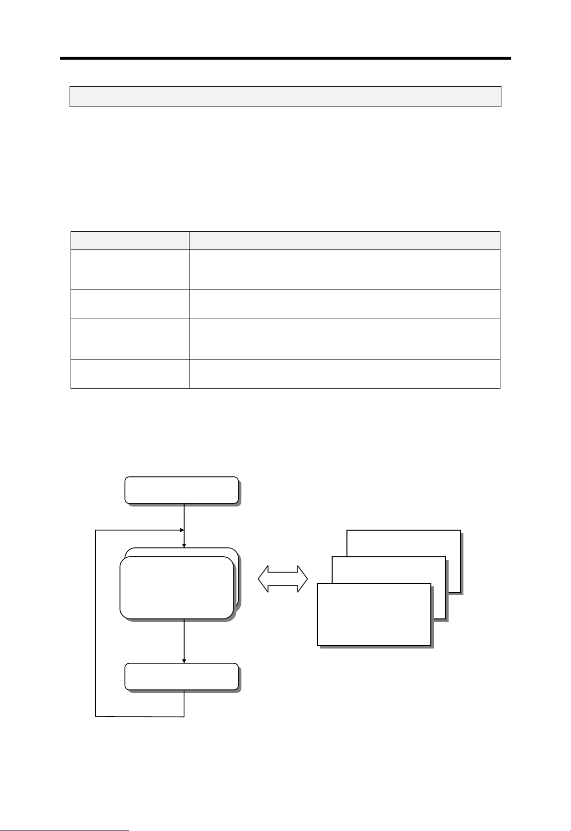
4.3.1 Classification of program
All functional elements need to execute a certain control process are called as a
‘program’. In MASTER-K series, a program is stored in the RAM mounted on a CPU
module or flash memory of a external memory module. The following table shows the
classification of the program.
Program type Description
The scan program is executed regularly in every scan. If the scan
Scan program
program is not stored, the CPU cannot execute not only the scan
program but also other programs.
Time-driven interrupt
program (TDI)
Process driven interrupt
program (PDI)
Subroutine program
The TDI programs are executed with a constant time interval
specified with parameter setting.
The PDI programs are executed only external interrupt input is
applied and the corresponding interrupt routine is enabled by EI
instruction.
The subroutine programs are executed when they are called by the
scan program with a CALL instruction.
4.3.2 Processing method
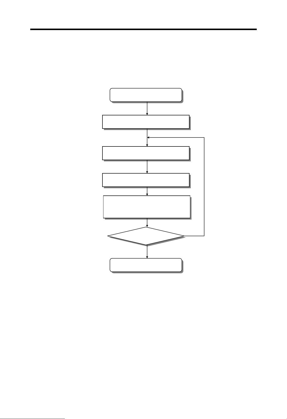
The following diagram shows that how the CPU module process programs when th e CPU
module is powered on or switched to RUN mode.
Start operation
Scan program
Subroutine program
PDI program
TDI program
END processing
4-10
Chapter 4 CPU modules MASTER-K
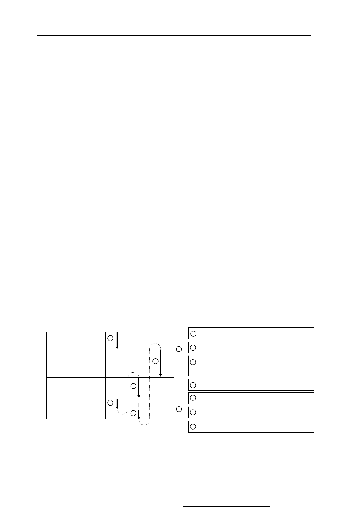
4.3.3 Interrupt processing
When an interrupt occurs, the CPU module will stop the current operation and execute
the corresponding interrupt routine. After finish the interrupt routine, the CPU resume the
sequence program from the stopped step.
MASTER-K series provides 2 types of interrupt. The TDI (Time driven interrupt) occurs
with the constant period, and PDI (Process driven interrupt) occurs with the status of
external input.
Before to use interrupt function in sequence program, the parameter setting should be
done properly. Then the corresponding interrupt routine should be written after END
instruction. (Refer chapter 4 for details) If interrupt routines are not matched with
parameter settings, an error occurs and the operation of CPU will be stopped.
To execute an interrupt routine, use the EI instruction to enable the corresponding
interrupt. The interrupt routine is not executed if an interrupt factor occurs before
execution of an EI instruction. Once an interrupt is enabled with EI instruction, it keeps
the enabled status until DI instruction is executed to disable the interrupt. When a CPU is
turned to RUN mode, all interrupts are disabled by default.
When multiple interrupt factors occur simultaneously, interrupt routines are executed
according to the priority given to the each interrupt. If an interrupt factor that has higher
priority occurs while other interrupt that has lower priority are executing, the interrupt
routine of lower priority will be stopped and the interrupt of higher priority will be executed
first. The following figure shows how a CPU handles multiple interrupts.
Scan Program
Interrupt routine 1
Interrupt routine 2
1
7
5
3
6
Program starts
1
2
Interrupt 2 occurs
2
Stop main program and execute interrupt
3
routine 2
4
Interrupt 1 occurs (higher priority)
5
Stop routine 2 and run routine 1
4
6
Finish routine 1 and return to routine2
7
Finish routine 2 and return to main
4-11

Chapter 4 CPU modules MASTER-K
1) Parameter setting
K200S K300S K1000S
Priority Type Period Priority Type Period Priority Type Period
0
1
2
:
:
7
Remark
Period is the interval of time driven interrupt occurring. It is variable from 10 ms to 60,000 ms
(60ms) by 10 ms.
Remark
Interrupt processing during momentary power failure:
If process-driven interrupts occur during a momentary power failure (power failure less than 20
ms), they are executed after the power is recovered. If a time-driven interrupt occurs two or
TDI0
TDI2
TDI5
:
:
INT7
10ms
25ms
100ms
0
1
2
:
:
:
13
TDI0
TDI2
TDI5
INT7
10ms
25ms
100ms
0
1
2
:
:
:
:
29
TDI0
TDI2
TDI5
INT15
10ms
25ms
100ms
more times during momentary power failure, it is executes only once after powe r is recovered.
During momentary power failure, the CPU keep measuring time and the period of momentary
power failure is included in the period of TDI.
4-12

Chapter 4 CPU modules MASTER-K
2) TDI (Time driven interrupt)
TDI occurs periodically with the constant interval assigned in parameter setting. The
interrupt routine of TDI starts with the TDINT instruction and ends with the IRET
instruction.
When multiple interrupt factors occur simultaneously, interrupt routines are executed
according to the priority given to the each interrupt. If an interrupt factor has higher priority
occurs while other interrupt of lower priority is executing, the interrupt routine of lower
priority will be stopped and the interrupt of higher priority will be executed first. Otherwise,
two interrupts are executed consequently.
The maximum numbers of TDI for K200S / 300S / 1000S are shown as following table.
PLC type Available TDI
K200S TDINT 0 ~ 7
K300S TDINT 0 ~ 13
K1000S TDINT 0 ~ 29
The following figure shows an example of TDI execution.
Used TDI
TDI 0 : occurs every 200ms
TDI 1 : occurs every 100ms
TDI 2 : occurs every 400ms
400ms
200ms
100ms 100ms 100ms 100ms
A B C A B A B CB B
Interrupt routines
A : The routine corresponding to TDI 0
B : The routine corresponding to TDI 1
C : The routine corresponding to TDI 2
200ms
4-13

Chapter 4 CPU modules MASTER-K
3) PDI (Process driven interrupt)
PDI occurs when the input status of interrupt module is changed from OFF to ON or from
ON to OFF. (Select by DIP switch setting) Since K200S does not have interrupt module,
PDI will occur when the input assigned as interrupt input by parameter setting is changed
from OFF to ON.
The execution order of multiple interrupts is similar as TDI. The following figure shows an
example of execution order of multiple PDI.
Scan Program
Interrupt routine 0
Interrupt routine 1
Interrupt routine 2
1
2
9
PDI
PDI
5
6
PDI
7
3
8
1
Program starts
2
Interrupt 2 occurs
3
Stop main program and run PDI routine 2
4
Interrupt 0 occurs (higher priority)
5
Stop routine 2 and execute routine 0
4
2 4 6
6
Interrupt 1 occurs (lower priority)
7
Finish routine 0 and execute routine 1
Finish routine 1 and resume routine 2
8
9
Finish routine 2 and back to main program
4-14

Chapter 4 CPU modules MASTER-K
4.3.4 Error handling
1) Error classification
Error occurs due to various causes such as PLC system errors, system configuration fault
or abnormal operation result. Errors are classified into fatal error that stops system
operation for safety, and ordinary error that continue system operation with informing the
user of error warning.
The causes of system error are as following;
- The hardware error
- System configuration error
- Operation error during execution of user program
- External device malfunction
2) Operation mode at error occurrence
In case of error occurrence, the CPU stores corresponding error code at error flags, and
stop / continue operation according to the error type.
① The hardware error
The system is changed to STOP mode when a fatal error such as CPU defection
occurs. When an ordinary error such as battery error occurs, the system keep its
operation status.
② System configuration error
This error occurs when actual hardware configuration conflicts with the configuration
assigned in parameter setting. The syste m is changed to the STOP mode.
③ Operation error during execution of user program
When a arithmetic operation error occurs, the system output error code at the
corresponding error flag and continue operating. If a scan time exceeds the watchdog
timer setting value or mounted I/O module is not normally controlled, the system is
switched to the STOP mode.
④ External device malfunction
The CPU can detect an external device malfunction with user program. If a fatal error
detected, the system is stopped. Otherwise, it continues operating.
Remark
1. When an error occurs, the error code is stored at special relay (F006 word).
2. Refer the appendix 1 ‘Flag list’ for det ails of error flags.
4-15
Chapter 4 CPU modules MASTER-K
4.4 Operation mode
The operation mode of CPU module can be classified into 4 modes such as RUN, STOP,
PAUSE, and DEBUG modes.
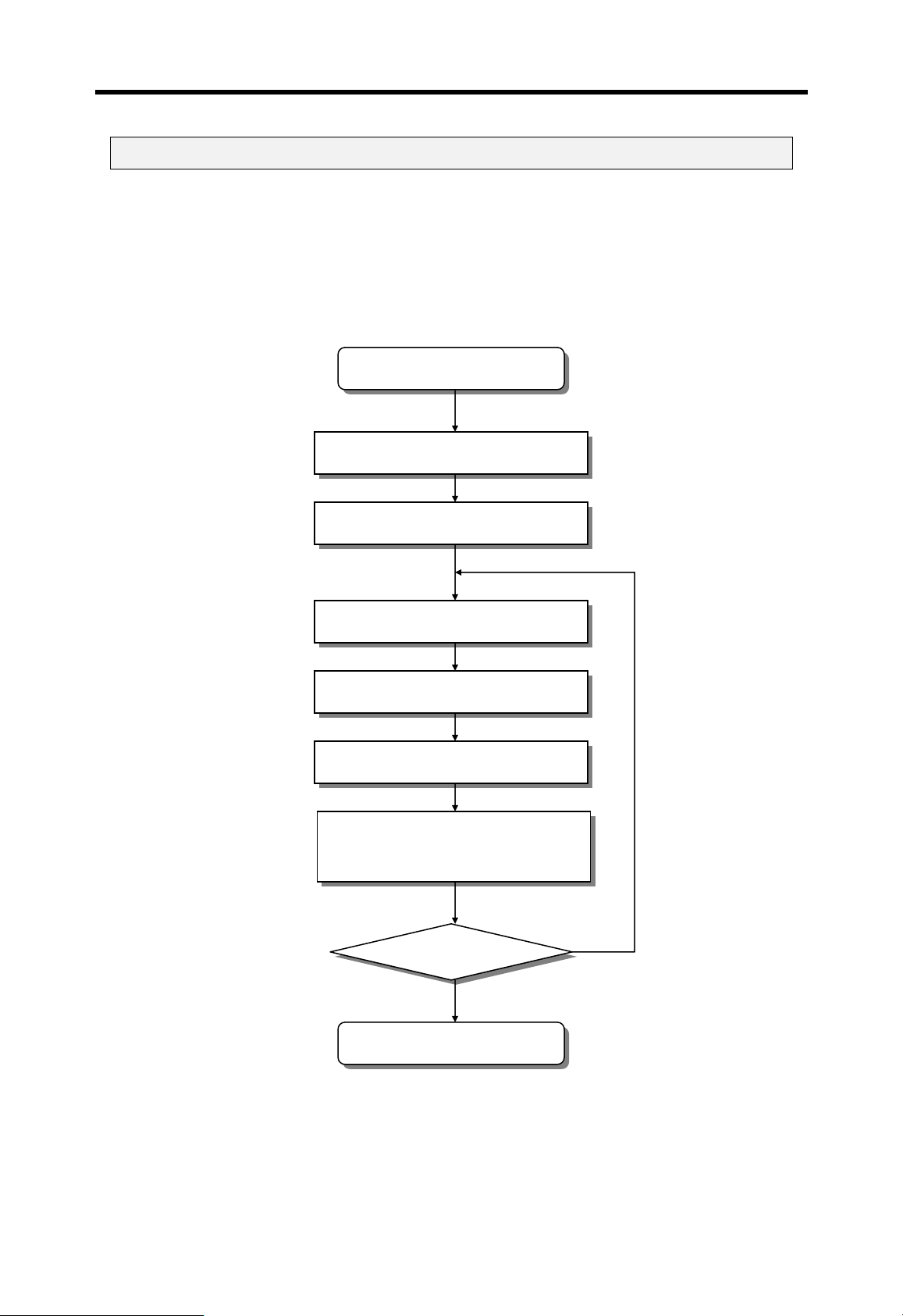
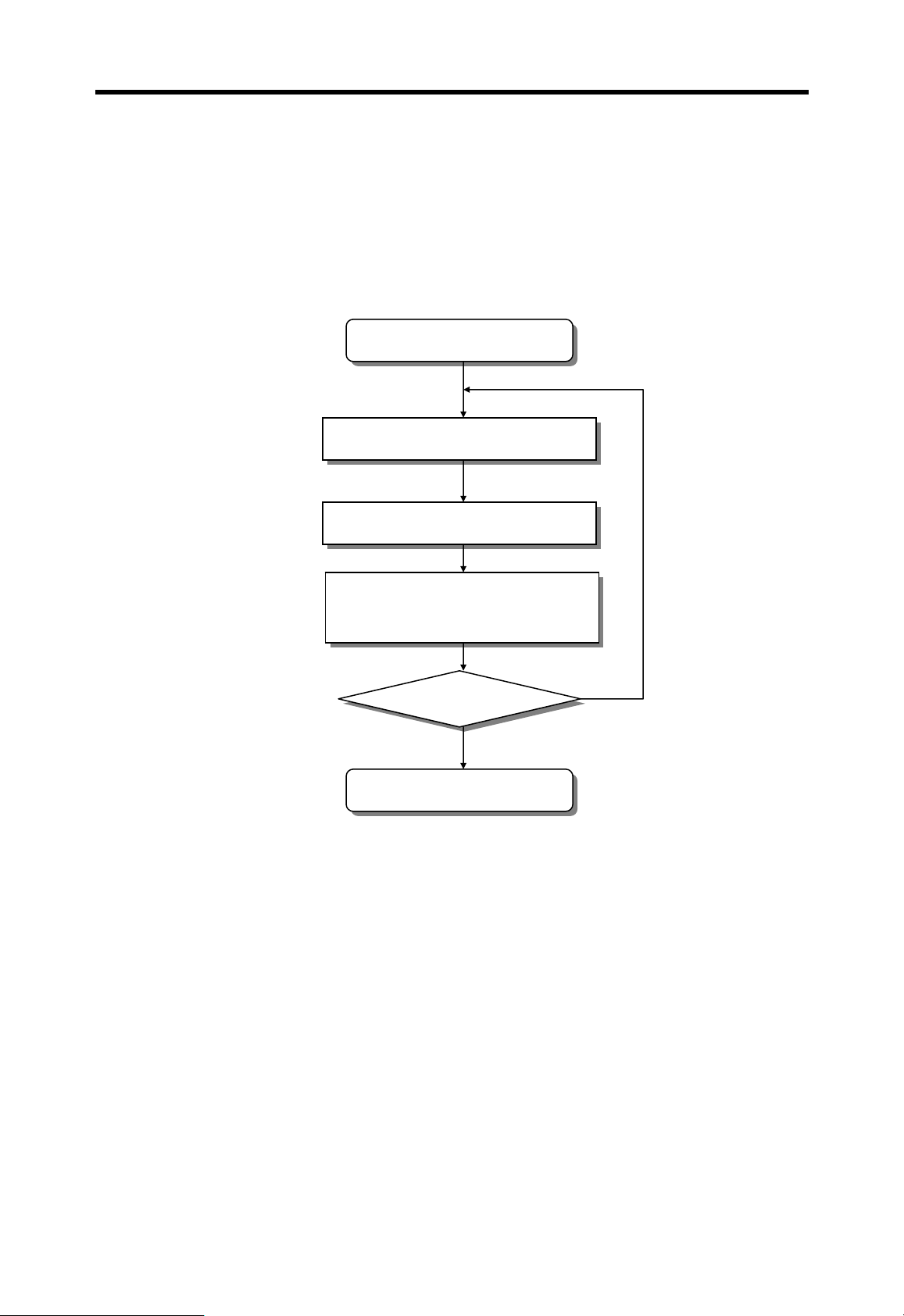
4.4.1 RUN mode
In the RUN mode, the CPU process user programs normally.
Start RUN mode
Clear the non-latched memory area
Check user program
Execution of user program
Self-diagnosis
I/O refresh
Execute communication service,
Update timer / counter
Mode changed?
Yes
Start other mode
4-16
No
Chapter 4 CPU modules MASTER-K
4.4.2 Stop mode
In the STOP mode, the CPU does not execute program. Program change through KGLWIN is possible in the remote STOP mode only.
External wiring check is also possible with the forced I/O on/off function.
Execute communication service,
Start STOP mode
Turn all outputs of f
Self-diagnosis
I/O refresh
Update timer / counter
No
Mode changed?
Yes
Start other mode
4-17
Chapter 4 CPU modules MASTER-K
4.4.3 PAUSE mode
In PAUSE mode, the CPU stops executing user program, but keeps the status of output
and internal memory.
When the mode is changed to RUN mode, the CPU restart executing user program from
the step at which the user program is stopped.
Start PAUSE mode
Execute communication service,
Self-diagnosis
I/O refresh
Update timer / counter
No
Mode changed?
Yes
Start other mode
4-18

Chapter 4 CPU modules MASTER-K
4.4.4 DEBUG mode
For debugging of user program, the MASTER-K 200S/300S/1000S provides the DEBUG
mode. In the DEBUG mode, the CPU executes user program according to the execution
condition as following;
① Step over : Executes just an operation unit (one instruction)
② Break point : Executes user program until the specified step (break point)
③ Device state : Execute user program until a device (bit or word) assigned to be
monitored is changed to the specified status (read, write, value)
④ Scan loop : Execute user program for specified number of scans
Start DEBUG mode
Clear the non-latched memory area
Stop operation
Execution of user program according
to the specified execution condition
Self-diagnosis
I/O refresh
Execute communication service,
Update timer / counter
Mode changed?
Yes
Start other mode
4-19
No

Chapter 4 CPU modules MASTER-K
Remark
It is forbidden to enter DEBUG mode from RUN or PAUSE mode.
Remark
In DEBUG mode, each interrupt program can be enabled / disabled sepa rately.
4.4.5 Operation mode change
1) The operation mode of CPU can be change by following methods;
① The mode key switch on the CPU module
② KGL-WIN connected to the CPU through loader port
③ KGL-WIN connected to the remote CPU through a fieldbus network
④ User command through a FAM or computer link module
⑤ The ‘STOP’ instruction of use r prog ram
2) Mode change by mode key switch
The following table shows how the operation mode is changed by mode key switch
Mode key switch Operation mode
RUN Local RUN
STOP Local STOP
PAU / REM Local PAUSE / Remote (RUN / STOP / PAUSE)
RUN Æ PAU / REM Local RUN Æ Local PAUSE
PAU / REM Æ STOP Local PAUSE / Remote Æ Local STOP
STOP Æ PAU / REM Local STOP Æ Remote STOP
PAU / REM Æ RUN Local PAUSE / Remote Æ Local RUN
Remark
The CPU operates continuously when the operation mode is changed as remote RUN Æ local
RUN
4-20

Chapter 4 CPU modules MASTER-K
3) Remote mode change
To change operation mode with KGL-WIN or KLD-150S, the mode key switch should be
in the remote STOP mode. (Mode key setting : STOP Æ PAU / REM)
Mode key
switch
PAU / REM
Mode change KGL-WIN FAM / Cnet
Remote STOP Æ Remote RUN O O
Remote STOP Æ Remote PAUSE X X
Remote STOP Æ DEBUG O O
Remote RUN Æ Remote PAUSE O O
Remote RUN Æ Remote STOP O O
Remote RUN Æ DEBUG X X
Remote PAUSE Æ Remote RUN O O
Remote PAUSE Æ Remote STOP O O
Remote PAUSE Æ DEBUG X X
DEBUG Æ Remote RUN X X
DEBUG Æ Remote PAUSE X X
DEBUG Æ Remote STOP O O
4-21

Chapter 4 CPU modules MASTER-K
4.5 Special functions of CPU module
4.5.1 RTC (Real Time Clock) function
MASTER-K 200S/300S/1000S series includes RTC function. (K200S-A does not have
RTC function) Clock operation by the RTC function is continued with a battery or super
capacitor when the CPU is powered off.
1) Clock data
Clock data is the data comprised of year, month, day, hour, minute, second, and date.
Data name Description
Year 4 digits of the Christian Era
Month 1 to 12
Day 1 to 31 (A leap year is distinguished automatically)
Hour 0 to 23 (24 hours)
Minute 0 to 59
Second 0 to 59
0 Sunday
1 Monday
2 Tuesday
Date
2) Precision
Max. 1.728 second per day (general temperature)
Remark
1. The RTC data does not have factory default setting. Please write a correct RTC data
before using RTC function first time.
2. If unreasonable RTC data is written to the CPU, the RTC function may operate abnormally.
Example : 13 (month) 32 (day)
3 Wednesday
4 Thursday
5 Friday
6 Saturday
4-22

Chapter 4 CPU modules MASTER-K
3) Read / write RTC data
① Read RTC data
The current RTC data
Memory Area
(Word)
F053 Lower 2 digits of year Month h9812
F054 Day Hour h2219
F055 Minute Second h3746
F056 Higher 2 digits of year Date h1902
Example : 1998. 12. 22. 19:37:46, Tuesday
② Write RTC data
There is two ways to write new RTC data to the CPU.
The first one is using a handy loader (KLD-150S) or graphic loader (KGL-WIN). For
detailed information, refer the user’s manual of KLD-150S or KGL-WIN.
The second one is write sequence program. By switching a special bit on, user can
replace the current RTC data with the preset data stored in a specified memory area. The
followings are the memory address of preset data and an example program.
The preset RTC data
Upper byte Lower byte
Description
Data
(BCD format)
Memory Area (Word) Description
K200S / K300S K1000S Upper byte Lower byte
D4990 D9990
D4991 D9991 Day Hour h1711
D4992 D9992 Minute Second h5324
D4993 D9993
Example : 1999. 1. 17. 11:53:24, Sunday
Lower 2 digits
of year
Higher 2 digits
of year
Month h9901
Date h1900
Data
(BCD format)
4-23

Chapter 4 CPU modules MASTER-K
M1904 : RTC data change bit
When the M1904 bit is switched on, the new data in D4990 ~ D4993 (K1000S :
D9990 ~ D9993) will be moved to F53 ~ F56. After data is moved, M1904 has to be
switched off immediately because current data will be updated every scan while
M1904 is on.
<Example program for K200S / K300S>
P000
Start switch
[ MOV h9901 D4990 ]
[ MOV h1711 D4991 ]
[ MOV h5324 D4992 ]
[ MOV h1900 D4993 ]
[ D M1904 ]
:1999 January
:17th 11 o’clock
:53min 24sec
:1999, Sunday
:Changing enable
Other Program
4-24
Chapter 4 CPU modules MASTER-K
4.5.2 Forced I/O setting
It is possible to output a designated data regardless of the result of operation. This
function is useful to check operation of the output modules and wiring between the output
modules and external devices.
K200S K300S K1000S
Forced I/O request bit M1910
The forced I/O address D4700 ~ D9700 ~
The forced I/O data D4800 ~ D9800 ~
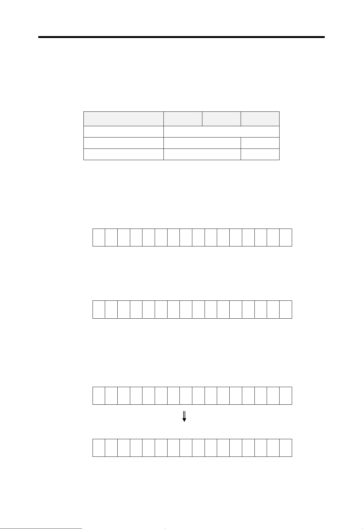
Example 1) Output h8721 to the P10 word by force (K200S / K300S)
a) Write the forced I/O data (h8721) to the corresponding data word. P10 is matched to
the D4810 word.
<D4810 word>
F E D C BA98765432 1 0
1 0 0 0 0 1 1 1 0 0 1 0 0 0 0 1
b) Write the forced I/O address (All bit = hFFFF) to the corresponding address word.
Write hFFFF to the D4710.
<D4710 word> ( 0 = disable forced I/O, 1 = enable forced I/O )
F E D C BA98765432 1 0
1 1 1 1 1 1 1 1 1 1 1 1 1 1 1 1
c) Switch on the forced I/O request bit (M1910).
d) Output of P10 word
(P : The previous result of operation )
F E D C BA98765432 1 0
P P P P P P P P P P P P P P P P
F E D C BA98765432 1 0
1 0 0 0 0 1 1 1 0 0 1 0 0 0 0 1
4-25

Chapter 4 CPU modules MASTER-K
Example 2) Switch On/Off the last bit of P07 word (K1000S)
a) Write the forced I/O data (h0001) to the corresponding data word. P10 is matched
to the D9807 word.
<D9807 word>
F E D C BA98765432 1 0
0 0 0 0 0000000000 0
b) Write the forced I/O address (last bit = h0001) to the corresponding address word.
Write h0001 to the D9707.
<D9707 word> ( 0 = disable forced I/O, 1 = enable forced I/O )
F E D C BA98765432 1 0
0 0 0 0 0000000000 0
c) Switch on the forced I/O request bit (M1910).
d) Output of P07 word
(P : The previous result of operation )
F E D C BA98765432 1 0
P P P P P P P P P P P P P P P P
1
1
F E D C BA98765432 1 0
P P P P PPPPPPPPPP P
1
4.5.3 Program edit in RUN mode
User can insert, delete, or change instructions of program while the CPU is running.
This function is useful to debugging or test-operation. Please refer the user’s manual
of KLD-150S or KGL-WIN for detail information.
Remark
The program edit in RUN mode can not be performed for the following instructions – JMP,
JME, CALL, SBRT, FOR, and NEXT instructions. Moreover, the program that has very long
scan time (2 seconds or more) can not be edited while the CPU is in the RUN mode.
4-26
Chapter 4 CPU modules MASTER-K
4.5.4 Self-diagnosis
1) WDT (Watch dog timer) function
The watch dog timer is an internal timer of a PLC to detect the error of hardware and a
sequence program. The default value is set as 200msec, and it is changeable with
parameter setting. Refer the MASTER-K programming manual for details on the
parameter setting.
The CPU resets the watch dog timer before step 0 is executed (after the END
processing is finished). When the END instruction has not been executed within the
set value due to an error occurred in the PLC or the long scan time of a sequence
program, the watch dog timer will times out. When a watch dog timer error is occurred,
all outputs of the PLC are turned OFF, and the ERR LED of the CPU will flashes.
(RUN LED will be turned OFF) Therefore, when use FOR ~ NEXT or CALL instruction,
insert WDT instruction to reset the watch dog timer.
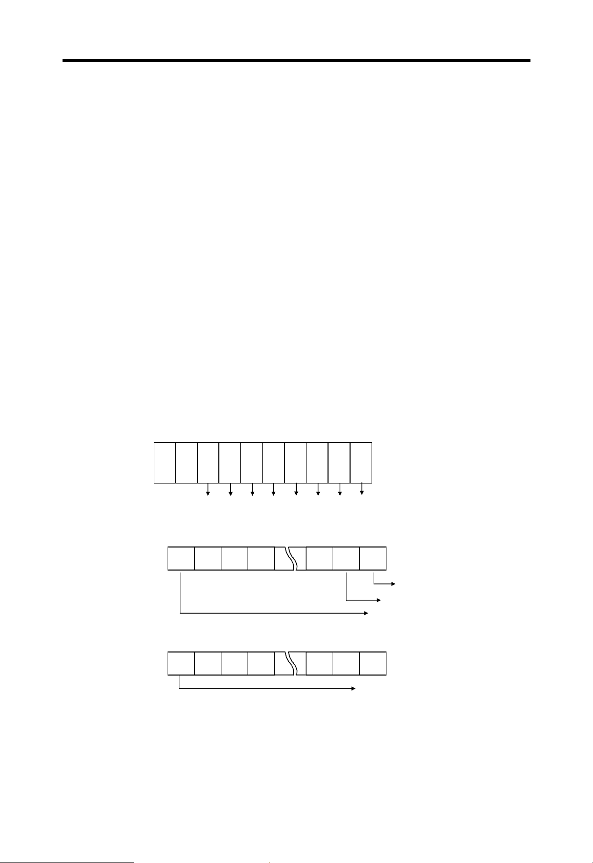
2) I/O module check function
If one or more I/O modules are mounted/dismounted while the PLC is powered, the
corresponding bit (F0040 ~ F0050 : 32 bits) will be switched on. If a module is
mounted improperly, the relevant bit will be switched on also.
P
C
W
R
P
U
Slot No :
1 234567
F004
(word)
MSB
1 1 1
LSB
Error occurred at slot 0
Error occurred at slot 1
Error occurred at slot 15
F005
(word)
MSB
1 1 1
LSB
Error occurred at slot 31
3) Battery check function
When the voltage of the battery for back-up the memory IC of CPU are lower than the
minimum back-up voltage, the BAT LED of CPU module will be turned on.
4-27
Chapter 4 CPU modules MASTER-K
4.5.5 Direct I/O refresh
To read or write the operation result immediately, MASTER-K 200S/300S/1000S provides
‘IORF’ instruction. When the IORF instruction is executed, the CPU refreshes I/O image
data area immediately. Please refer the MASTER-K instruction manual for details.
4.5.6 System error history
When the system is stopped by error occurrence, the CPU stores the error occurrence
time and error code to the special data register area. The most recent 16 error occurring
times and error codes are stored in the special data register.
1) Special data register
CPU type
K200S K300S K1000S
D4901 ~ D4904 D9901 ~ D9904 The latest error information
D4905 ~ D4908 D9905 ~ D9908 The 2nd latest error information
Device
: : :
D4961 ~ D4964 D9961 ~ D9964 The 16
2) Description of each word
Device
Contents Description
K200S K300S K1000S
D4901 D9901 h9905 Year : 99, Month : 5
D4902 D9902 h2812 Date : 28, Hour : 12
D4903 D9903 h3030 Minute : 30, Second : 30
D4904 D9904 h0001 Error code (h0001)
3) Clear error data
Use a ‘data clear’ function of KGL-WIN or KLD-150S
Description
th
latest error information
Remark
The system error history function is not available with K3P-07AS because it does not have
RTC function.
4-28
Chapter 4 CPU modules MASTER-K
4.6 Memory configuration
4.6.1 Memory map of K200S / K300S
P00
P
1
M189
M190
M191
K00
K31
F00
F63
L00
L63
Bit Data Area Word Data Area User Program Area
0 ~ F 0000 ~ FFFF
D0000
I/O relay
(See the remark
)
“P”
Auxiliary relay
(3,040 points)
Special auxiliary relay
(32 points)
“M”
“M”
Keep relay
(512 points)
“K”
D4500
D4999
T000
T255
T000
Data Register
Reserved for special usage
Timer preset value
(256 words)
Timer elapsed value
(256 words)
“D”
Word
Parameter setting area
User Program
Area
MK300S :
15k steps
MK200S : 7k steps
T255
Special relay
(1,024 points)
“F”
C000
Counter preset value
(256 words)
C255
Link relay
(1,024 points)
“L”
C000
Counter elapsed value
(256 words)
T000
T191
T192
T255
C000
C255
Timer relay (100ms)
192 points
Timer relay (10ms)
64 points
Counter relay
256 points
“T”
“T”
“C”
S00
S99
Remark
P∴∴
Ste p Controller
(100 x 100 steps)
S00.00~S99.99
1
:
“S”
K200S : P15 (256 points)
K300S : P31 (512 points)
P63 (1,024 points) Æ In 3.0 or higher CPU O/S version
4-29

Chapter 4 CPU modules MASTER-K
4.6.2 The memory map of K1000S
Bit Data Area Word Data Area User Program Area
0 ~ F 0000 ~ FFFF
P00
P63
M000
M189
M190
M191
K00
K31
F00
F63
L00
L63
I/O relay
(1,024 points
)
“P”
Auxiliary relay
(3,040 points)
Special auxiliary relay
(32 points)
Keep relay
(512 points)
“M”
“M”
“K”
Special relay
(1,024 points)
Link relay
(1,024 points)
“F”
“L”
D0000
D9500
D9999
T000
T255
T000
T255
C000
C255
C000
Data Register
Reserved for special usage
Timer preset value
(256 words)
Timer elapsed value
(256 words)
Counter preset value
(256 words)
Counter elapsed value
(256 words)
“D”
Parameter setting area
Word
User Program
Area
(30k steps)
T000
T191
T192
T255
C000
C255
Timer relay (100ms)
192 points
Timer relay (10ms)
64 points
Counter relay
256 points
“T”
“T”
“C”
S00
S99
Ste p Controller
(100 x 100 steps)
S00.00~S99.99
“S”
4-30
Chapter 4 CPU modules MASTER-K
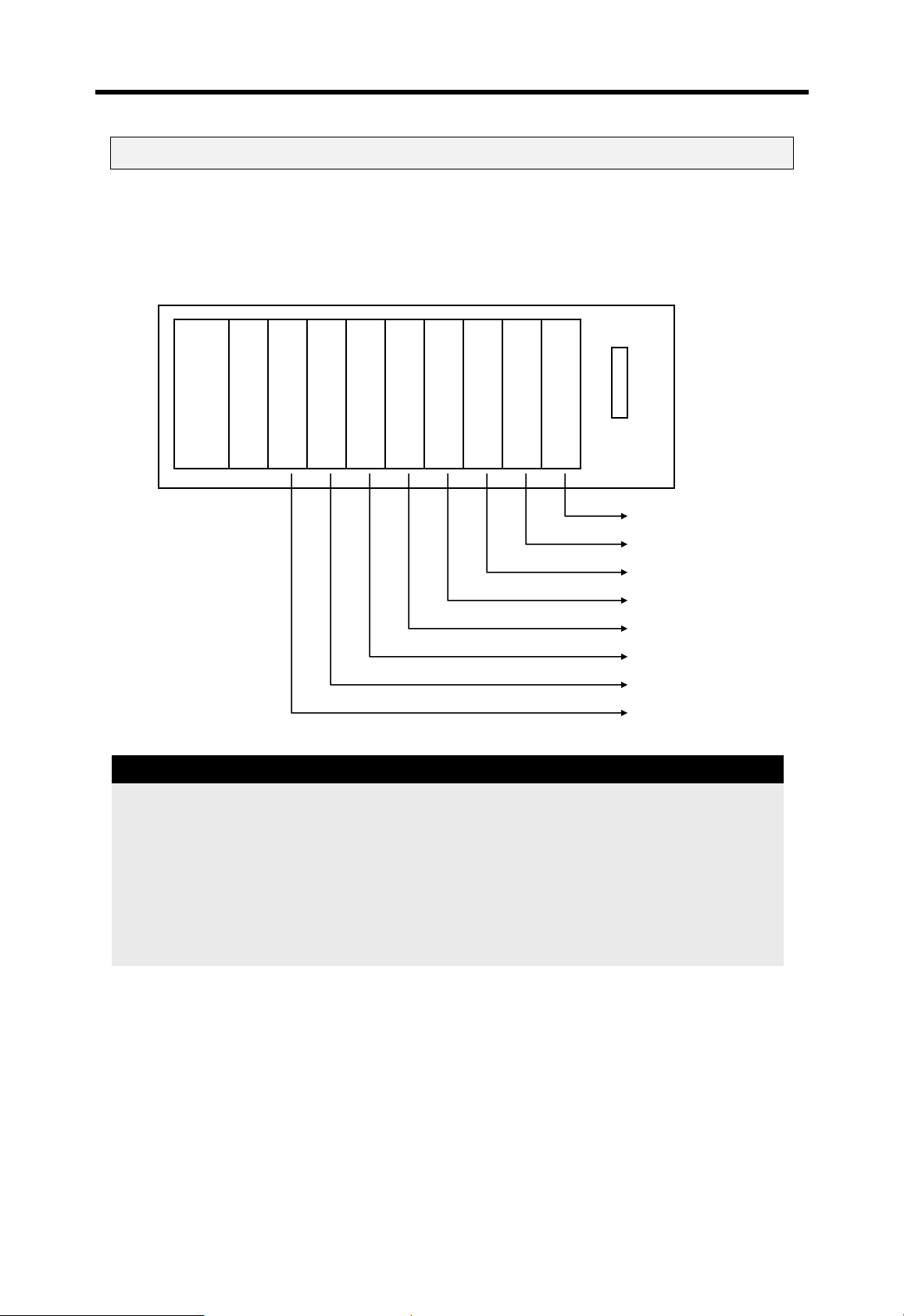
4.7 Assign I/O address
To read / write data I/O and special function modules, the CPU assigns I/O address (P
area) to each modules according to the module type. I/O address starts from P00 (word),
and it is assigned from left to right. The following figure shows an example of I/O address
allocation.
Main base (8 slots)
Remark
Power module
Input (16 points)
CPU module
Output (16 points)
Input (32 points)
Input (64 points)
Output (32 points)
D/A module (8ch)
A/D module(4ch)
Fnet module
P120 ~ P12F (1word)
P1 10 ~ P11F (1 word)
P100 ~ P10F (1 word)
P080 ~ P09F (2 words)
P070 ~ P07F (1 word)
P030 ~ P06F (4 words)
P010 ~ P02F (2 words)
P000 ~ P00F (1 word)
1. Special function modules occupy various I/O addresses according to the type of module.
Please see the user’s manual of each special function module for details
2. Special function modules can be mounted on any slots of main / expansion base. There is
also no limit on the number of special function modules mountable on a base.
3. In 2.0 or lower K300S/1000S CPU OS version , network module can be mounted on the
main base only.
4-31
Chapter 4 CPU modules MASTER-K
8
61 8
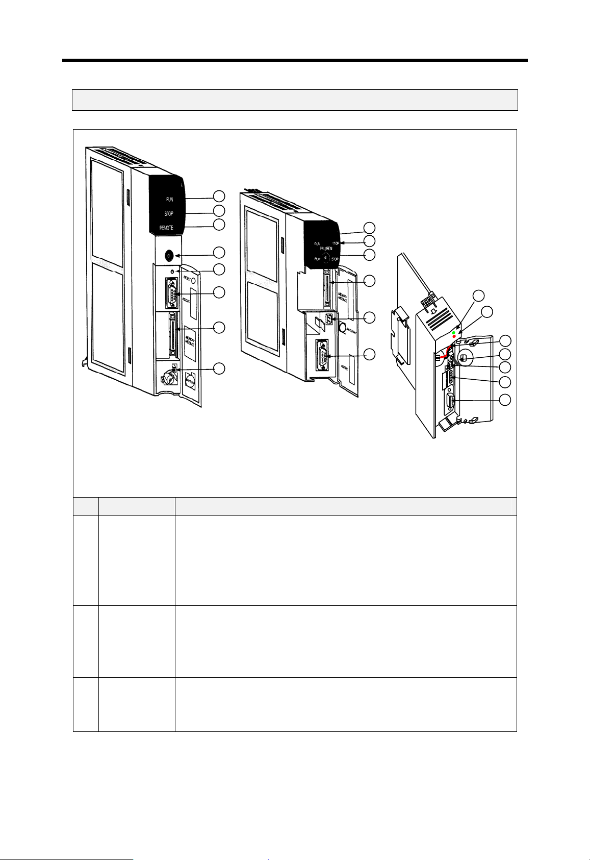
4.8 Parts names
K7P-30AS
1
K4P-15AS
2
4
7
MK1000S
MK300S MK200S
No Name Description
Shows the operation status of CPU module
On : the CPU is on the Local RUN or remote RUN mode
1 RUN LED
Off : the CPU detects improper power supply
the CPU is not on the RUN mode (STOP or PAUSE mode)
the CPU detects an fatal error that stop the operation
Shows the operation status of CPU module
On : the CPU is on STOP mode
2 STOP LED
Off : the CPU is not on the STOP mode (RUN or PAUSE)
4
A
Flickering : An error i s detected during operation
Only K1000S has remote LED.
3 Remote LED
On : the CPU is on the remote (RUN / STOP / PAUSE / DEBUG) mode
Off : the CPU is on the local (RUN / STOP / PAUSE) mode
4-32
Chapter 4 CPU modules MASTER-K
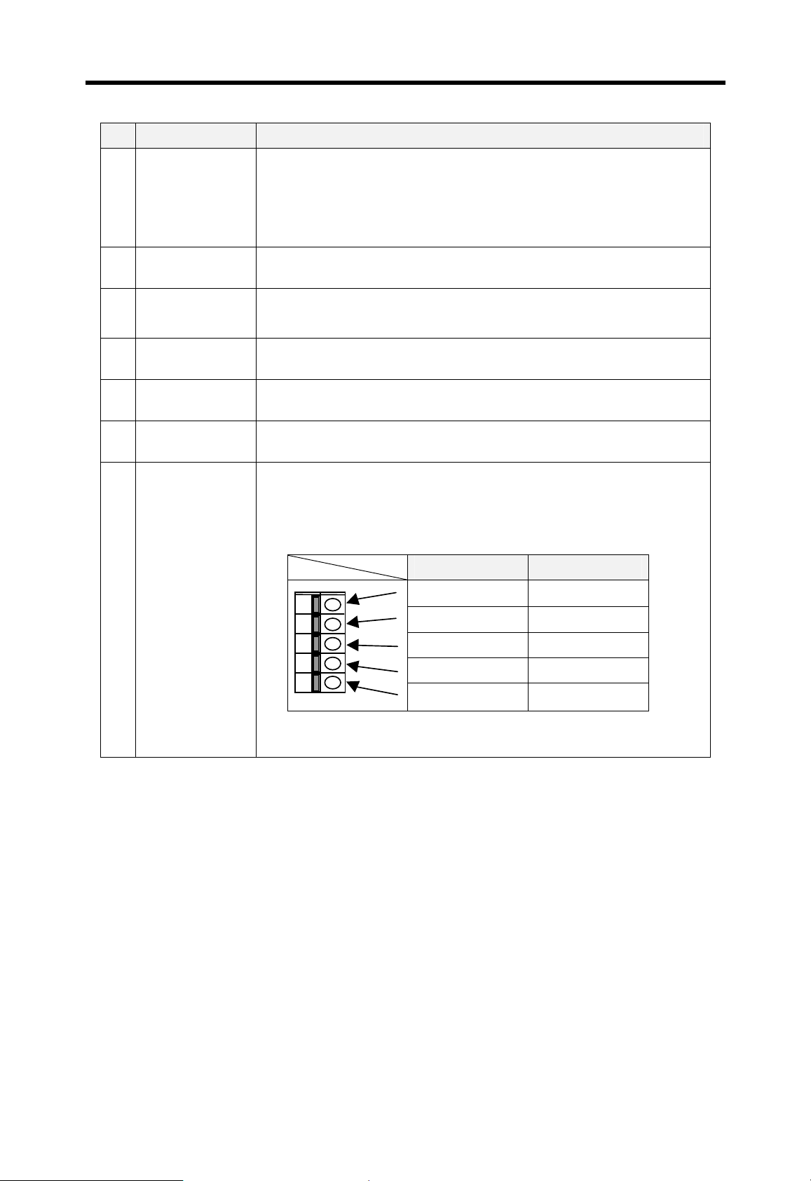
No Name Description
Set a operation mode of CPU module
4 Mode key switch
Manual reset
5
switch
RS-232C
6
connector
Memory module
7
connector
Battery
8
connector
Memory setting
9
DIP switch
Terminal block
for special
A
functions
- RUN : Executes user program
- STOP : Stop executing user program
- PAU / REM : Pause or remote mode
Restart the CPU module ( Available in K1000S only)
Connector for peripheral devices uses RS-232C protocol.
(Example : KGL-WIN)
Connector for external memory module
Connector for back-up battery
Refer the Chapter 6
K3P-07AS : Not applicable
K3P-07BS : RS-422/485 interface terminal block
K3P-07CS : High speed counter input terminal block
K3P-07BS K3P-07CS
RDA
RDB
SDA COM
φA 24V
φB 24V
(Please refer chapter 13 and 16 for details)
SDB PRE 24V
SG PRE 0V
4-33

Chapter 5 Battery
5 Battery........................................................................................................ 5-1
5.1 Specifications............................................................................................................ 5-1
5.2 Handling instructions............................................................................................... 5-1
5.3 Replacement procedure........................................................................................... 5-2

Chapter 5 Battery MASTER-K
5 Battery
5.1 Specifications
Item Description
Rated voltage 3.0VDC
Lifetime 5 years
Purpose User program and data back-up, RTC operatio n during power-off
Type Lithium battery, 3VDC
Dimension (mm)
φ 14.5 × 26
5.2 Handling instructions
1) Do not heat or solder the terminals of battery.
2) Do not measure its voltage with a tester, or short circuit.
3) Do not disassemble
Remark
The K300S and K1000S CPU modules have super capacitor to back-up during battery
replacement. The super capacitor can backup the user program and latch area about 30
minutes. However, be careful to finish battery replacement as soon as possible.
Caution
The K200S CPU module does not have super capacitor or other device to backup during
battery replacement. Therefore, the user program and latch area will be erased if the battery
is removed while the power is off. Make sure to turn on the power of CPU during battery
replacement.
5-1

Chapter 5 Battery MASTER-K
5.3 Replacement procedure
Replacement battery
Open the cover of CPU module
Remove the battery from CPU module
Connect a new battery
Check the STOP LED of CPU module
Is it flicking with 2sec
period?
Yes
The battery is defected.
No
Done
5-2

Chapter 6 Memory module
6 Memory module......................................................................................... 6-1
6.1 Structure....................................................................................................................6-1
6.2 Specifications............................................................................................................ 6-1
6.2.1 K300S / K1000S ....................................................................................................6-1
6.2.2 K200S....................................................................................................................6-2
6.3 How to use the memory module..............................................................................6-2
6.3.1 Write a program into memory module ................................................................... 6-2
6.3.2 Execute the program of memory module...............................................................6-3

Chapter 6 Memory module MASTER-K
6 Memory module
In this chapter, it is described how to store user program in the memory module and run a
PLC system with memory module.
The memory module of MASTER-K 200S/300S/1000S series uses flash memory. To read /
write of memory module, insert a memory module into the memory module socket on the
CPU module. No other device such as ROM writer is required.
The K200S includes a flash memory on the CPU module, so it does not have external
memory module.
6.1 Structure
Housing
(Flash memory is included)
Connector
6.2 Specifications
6.2.1 K300S / K1000S
The K300S / K1000S CPU module will operate as flash memory mode automatically if the
memory module is mounted in a STOP mode and then the CPU module is switched as
RUN mode. The following table shows specifications of memory module of K300S /
K1000S series.
K300S K1000S Type
Item
Memory device Flash memory Flash memory
K4M-32S K764S
Capacity 128k byte (32k steps) 256k byte (64k steps)
Weight 10g 14g
6-1

Chapter 6 Memory module MASTER-K
6.2.2 K200S
The K200S series includes a flash memory, and the operation mode (RAM mode / Flash
memory mode) can be selected by setting DIP switch on the front of CPU module.
DIP switch setting Description
ROM MODE
TEST MODE
2
1
1: Off, 2: Off
When the CPU starts with RUN mode, the CPU module
operates with the program stored in RAM. (the contents
ON
of flash memory is ignored.)
ROM MODE
TEST MODE
2
1
1: Off, 2: On
When the CPU starts with RUN mode, the CPU module
operates with the program stored in flash memory.
ON
6.3 How to use the memory module
6.3.1 Write a program into memory module
When insert memory module into the memory connector of CPU module, make sure the
power of CPU is turned off. To write a program on memory module, the CPU should be
on STOP mode.
1) Download a program to be written on a memory module. (Use KGL-WIN or KLD-
150S)
2) Switch the CPU to the STOP mode and turn of f power.
3) Insert a memory module into the memory module connector of CPU module.
4) Turn on the power
5) Execute flash memory write function with KGL-WIN or KLD-150S.
Remark
1. Refer the user’s manual of KGL-WIN or KLD-150S for details.
2. In case of K200S, switch the CPU to STOP mode and select flash memory write function of
KGL-WIN or KLD-150S.
6-2

Chapter 6 Memory module MASTER-K
y
6.3.2 Execute the program of memory module
The CPU module checks the memory module is mounted or not when the CPU starts
RUN mode. Then, if the memory module is mounted, the CPU module reads the program
and parameter of memory module and writes it to the internal RAM of CPU module to
execute the program of memory module.
The following procedure shows how to operate a CPU with flash run mode.
1) Switch the CPU to STOP mode and then turn off power.
2) Insert memory module into the memory module connector of CPU module
3) Turn on the power and then switch the CPU module to RUN mode.
4) Check the CPU is operating in flash memory mode by monitoring special relays.
F0007 : Turns on when memory module is mounted
F0005 : Turns on when the CPU operates in flash memory mode.
Remark
1. If the CPU starts RUN mode when memory module is mounted, the program and
parameter of internal RAM of CPU module will be replaced with those of memory module
immediately. (There is no warning message) Therefore, when write program into memory
module, make sure the CPU is in STOP mode.
2. When revise program with KGL-WIN or KLD-150S, remove memory module from the
memory module connector of CPU module. If the CPU is changed to RUN mode with
memory module mounted, the program and parameter of CPU module is replaced as
memor
module and all changes of program will be lost.
6-3

Chapter 7 I/O modules
7 I/O modules................................................................................................ 7-1
7.1 Notes on selecting I/O modules .............................................................................. 7-1
7.2 Digital input modules................................................................................................7-2
7.2.1 8 points 12/24VDC input module (source / sink type).........................................7-2
7.2.2 16 points 12/24VDC input module (source/sink type).........................................7-3
7.2.3 16 points 12/24 VDC input module (source type)...............................................7-4
7.2.4 16 points 24VDC input module (source/sink type)..............................................7-5
7.2.5 32 points 12/24 VDC input module (source/sink type)........................................ 7-6
7.2.6 32 points 12/24 VDC input module (source type)...............................................7-7
7.2.7 32 points 24VDC input module (source/sink type)..............................................7-8
7.2.8 64 points 12/24VDC input module (source/sink type).........................................7-9
7.2.9 8 points 110VAC input module.......................................................................... 7-11
7.2.10 16 points 110VAC input module......................................................................7-12
7.2.11 32 points 110VAC input module......................................................................7-13
7.2.12 8 points 220VAC input module ....................................................................... 7-14
7.2.13 16 points 220VAC input module ..................................................................... 7-15
7.2.14 32 points 220VAC input module ..................................................................... 7-16
7.2.15 Interrupt input module.....................................................................................7-17
7.3 Digital output modules........................................................................................... 7-18
7.3.1 8 points relay output module............................................................................. 7-18
7.3.2 16 points relay output module...........................................................................7-19
7.3.3 32 points relay output module...........................................................................7-20
7.3.4 8 points triac output module..............................................................................7-21
7.3.5 16 points triac output module............................................................................7-22
7.3.6 32 points triac output module............................................................................7-23
7.3.7 16 points transistor output module (sink type)..................................................7-24
7.3.8 32 points transistor output module (sink type)..................................................7-25
7.3.9 64 points transistor output module (sink type)..................................................7-26
7.3.10 16 points transistor output module (source type) ........................................... 7-28
7.3.11 32 points transistor output module (source type) ........................................... 7-29
7.3.12 64 points transistor output module (source type) ........................................... 7-30
7.4 Digital input / output hybrid modules...................................................................7-31
7.4.1 8 points 12/24VDC input + 8 points relay output...............................................7-31
7.4.2 8 points 12/24VDC input + 8 points transistor output........................................7-33

Chapter 7 I/O modules MASTER-K
7 I/O modules
7.1 Notes on selecting I/O modules
When selects I/O module for K200S/300S/1000S PLC system, please refer the following
instructions.
1) The digital input module is classified as current sink input and current source input. The
external wiring with input device is various according to the type of digital input module.
Please select suitable digital input module type with considering of specification of input
device.
2) The maximum points that can be turn simultaneously on differ with each module. Before
to select a digital I/O module, check the specification of module.
3) When a very fast response time (less than a scan time) is required, select an interrupt
module. However, only one interrupt module can be mounted on a system.
4) The lifetime of relay is described as total on/off times (No load : 10 million times, With
load : 0.1 ~ 3 million times). Therefore, if the frequency of on/off operation of relay is
higher, the lifetime of relay is shorter. Please use transistor or SSR output module for high
frequency operation.
5) When a large and/or inductive load is connected directly to the output module, it may
cause malfunction of the output module. It is highly recommended customers to connect
an external relay or SSR between an output module and large inductive load for improved
reliability and maintenance of PLC system.
7-1

Chapter 7 I/O modules MASTER-K
7.2 Digital input modules
7.2.1 8 points 12/24VDC input module (source / sink type)
K200S Type
Specification
Input points 8 points
Insulation method Photo coupler insulation
Rated input voltage 12VDC 24VDC
Rated input current 3 mA 7 mA
Operating input voltage 10.2 ~ 28.8 VDC ( ripple : 5% or less )
Max. simultaneously on 8 points (100%)
On voltage / current 9.5 VDC or higher/ 3.5 mA
Off voltage / current 5 VDC or less/ 1.5 mA
G6I-D21A
Input impedance
Response
time
Common 8 points / 1 com
Internal current consumption 40 mA
Operation indicator LED display
External wiring
Weight 120 g
Wiring diagram
Off Æ On 5 msec or less
On Æ Off 5 msec or less
About 3.3kΩ
9 points terminal block connector ( M3×6 screw )
0
1
2
3
4
5
6
7
COM
7-2
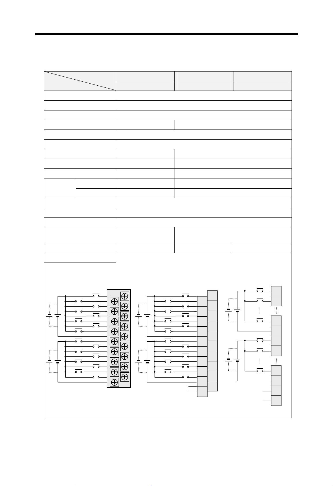
Chapter 7 I/O modules MASTER-K
A
A
7.2.2 16 points 12/24VDC input module (source/sink type)
K200S K300S K1000S Type
Specification
Input points 16 points
Insulation method Photo coupler insulation
Rated input voltage 12 / 24 VDC
Rated input current 3 / 7 mA 5 / 11mA
Operating input voltage 10.2 ~ 26.4 VDC ( ripple : 5% or less )
Max. simultaneously on 16 points (100%)
On voltage / current 9.5 VDC / 3.5 mA 9.5 VDC / 4.0 mA
Off voltage / current 5 VDC / 1.5 mA 5 VDC / 1.0 mA
G6I-D22A G4I-D22A G3I-D22A
Input impedance
Response
time
Off Æ On 5 msec or less 10 msec or less
On Æ Off 5 msec or less 10 msec or less
About 3.3kΩ About 2.2kΩ
Common 8 points / 1 com
Internal current consumption 70 mA
Operation indicator LED display
External wiring
18 points terminal
block connector
20 points terminal block connector
Weight 150 g 250 g 370 g
Wiring diagram
[ G6I-D22A ] [ G4I-D22A ] [ G3I-D22A ]
1
3
5
7
8
C
E
0
2
4
6
9
B
D
F
1
3
5
7
8
C
E
COM
0
2
4
6
COM
9
B
D
F
N.C
N.C
10
12
14
16
18
20
1
2
3
4
5
6
7
8
9
11
13
15
17
19
0
1
7
COM
8
9
F
COM
N.C
N.C
1
2
8
9
10
11
17
18
19
20
7-3

Chapter 7 I/O modules MASTER-K
A
A
7.2.3 16 points 12/24 VDC input module (source type)
K200S K300S Type
Specification
Input points 16 points
Insulation method Photo coupler insulation
Rated input voltage 24 VDC 12 / 24 VDC
Rated input current 7 mA 5 / 11mA
Operating input voltage 20.4~28.8 VDC (ripple: 5% or less) 10.2~26.4 VDC (ripple: 5% or less)
Max. simultaneously on 16 points (100%)
On voltage / current 15 VDC / 4.3 mA 9.5 VDC / 4.0 mA
Off voltage / current 5 VDC / 1.7 mA 5 VDC / 1.0 mA
G6I-D22B G4I-D22B
Input impedance
Response
time
Off Æ On 5 msec or less 10 msec or less
On Æ Off 5 msec or less 10 msec or less
About 3.3kΩ About 2.2kΩ
Common 8 points / 1 com
Internal current consumption 70 mA
Operation indicator LED display
External wiring 20 points terminal block connector 20 points terminal bl ock connector
Weight 150 g 250 g
Wiring diagram
[ G6I-D22B ] [ G4I-D22B ]
0
1
2
3
4
5
6
7
8
9
B
C
D
E
F
1
3
5
7
8
C
E
COM
0
2
4
6
COM
9
B
D
F
N.C
N.C
2
4
6
8
10
12
14
16
18
20
1
3
5
7
9
11
13
15
17
19
7-4
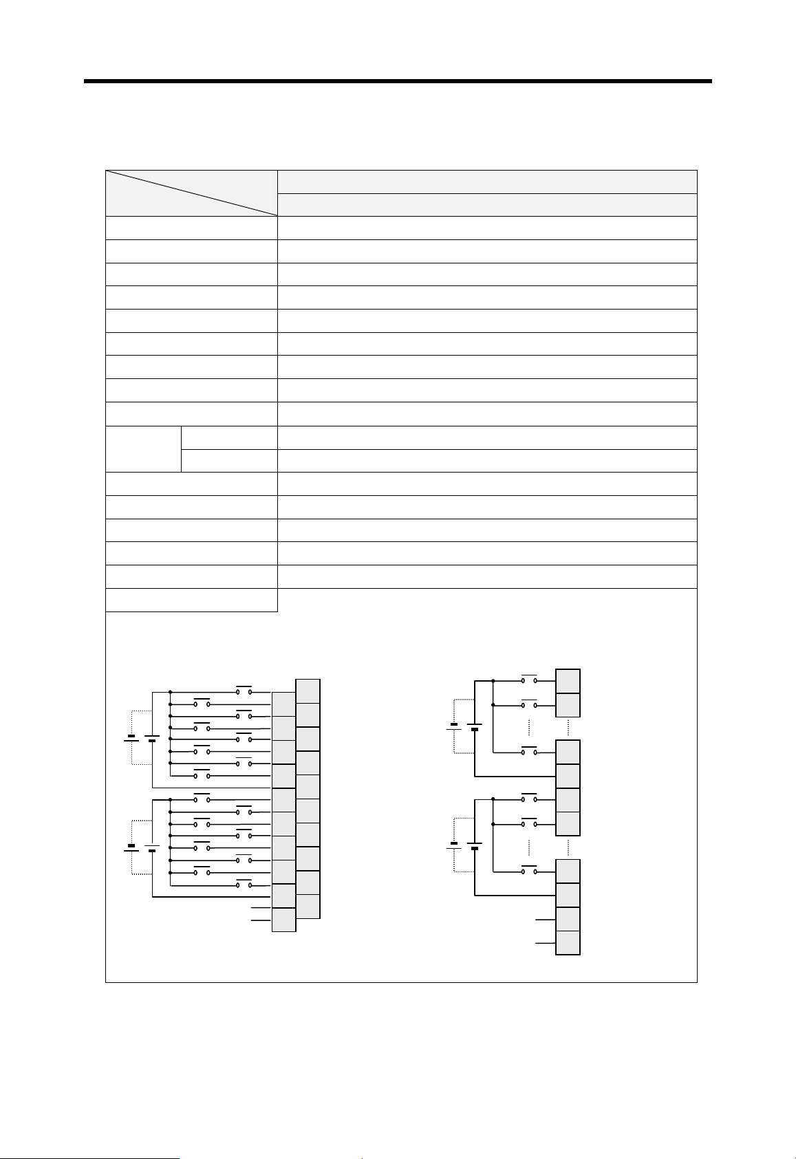
Chapter 7 I/O modules MASTER-K
A
7.2.4 16 points 24VDC input module (source/sink type)
K300S Type
Specification
Input points 16 points
Insulation method Photo coupler insulation
Rated input voltage 24 VDC
Rated input current 7mA
Operating input voltage 20.4 ~ 28.8 VDC ( ripple : 5% or less )
Max. simultaneously on 16 points (100%)
On voltage / current 17 VDC / 5.2 mA
Off voltage / current 8 VDC / 2.4 mA
G4I-D22C
Input impedance
Response
time
Off Æ On 10 msec or less
On Æ Off 10 msec or less
About 3.3kΩ
Common 8 points / 1 com
Internal current consumption 70 mA
Operation indicator LED display
External wiring 20 points terminal block connector
Weight 250 g
Wiring diagram
[ G4I-D22C ] [ G3I-D22C ]
0
1
7
COM
8
9
F
COM
N.C
N.C
10
11
17
18
19
20
1
3
5
7
8
C
E
COM
0
2
4
6
COM
9
B
D
F
N.C
N.C
2
4
6
8
10
12
14
16
18
20
1
3
5
7
9
11
13
15
17
19
1
2
8
9
7-5
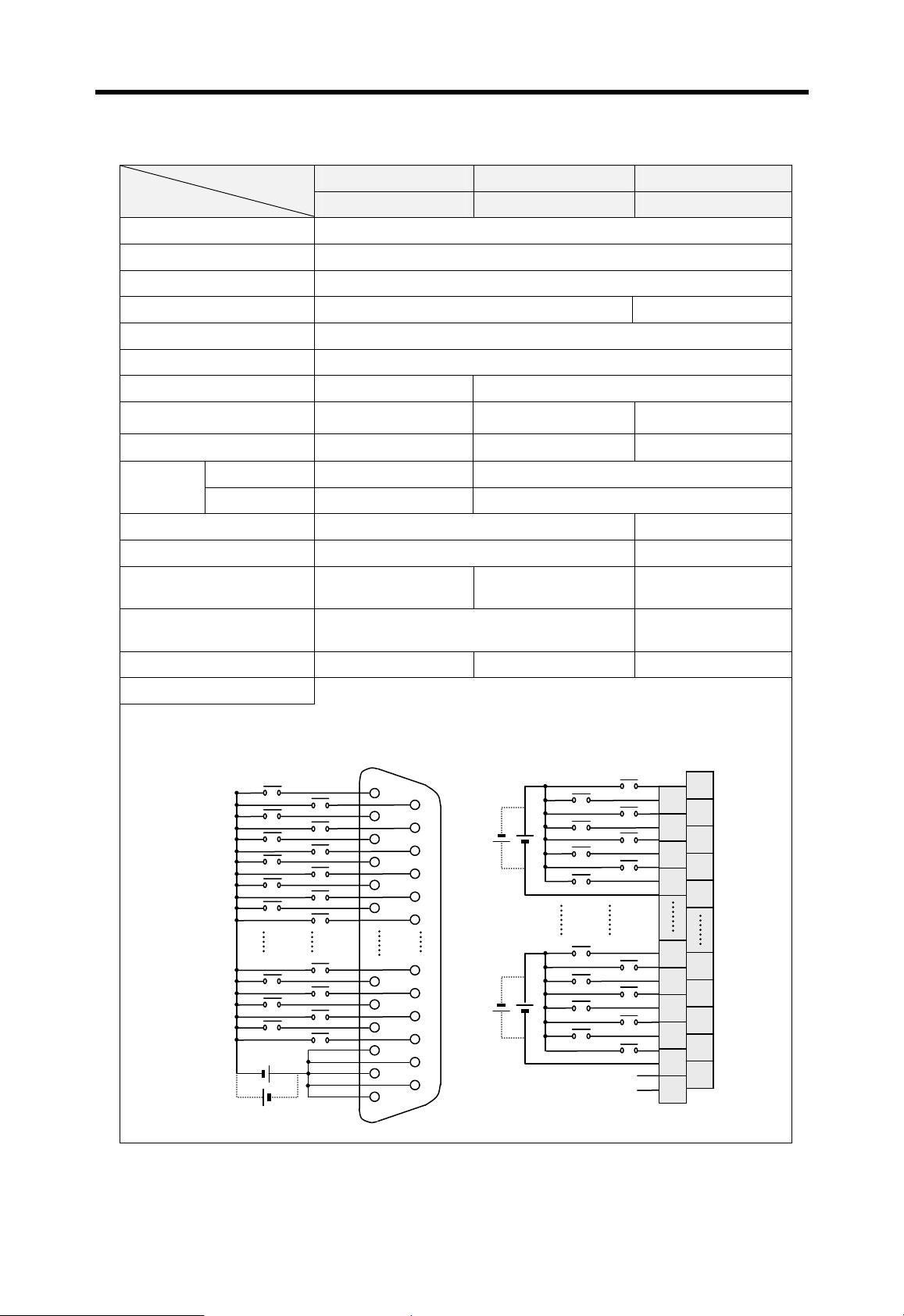
Chapter 7 I/O modules MASTER-K
A
A
A
7.2.5 32 points 12/24 VDC input module (source/sink type)
K200S K300S K1000S Type
Specification
Input points 32 points
Insulation method Photo coupler insulati on
Rated input voltage 12 / 24 VDC
Rated input current 3 / 7 mA 5 / 11mA
Operating input voltage 10.2 ~ 26.4 VDC (ripple: 5% or less)
Max. simultaneously on 60% simultaneously ON
On voltage / current 9.5 VDC / 3.5mA 9.5 VDC / 4.0 mA
Off voltage / current 5 VDC / 1.5 mA 5 VDC / 1.0 mA 6VDC / 1.0 mA
G6I-D24A G4I-D24A G3I-D24A
Input impedance
Response
time
Off Æ On 5 msec or less 10 msec or less
On Æ Off 5 msec or less 10 msec or less
About 3.3kΩ About 3.3kΩ About 2.2kΩ
Common 32 points / 1 com 8 points / 1 com
Internal current consumption 75 mA 125 mA
Operation indicator
LED turns on at ON
state of input
External wiring 37 pin D-sub connector
16-point indication by
selection switch
LED turns on at ON
state of input
38 points terminal
block connector
Weight 110 g 190 g 460 g
Wiring diagram
[ G6I-D24A ] & [ G4I-D24A ] [ G3I-D24A ]
00
02
04
06
08
0
1
1C
1E
01
03
05
07
09
0B
19
1B
1D
1F
01
03
05
07
18
1
1C
1E
COM4
00
02
04
06
COM1
19
1B
1D
1F
N.C
N.C
2
4
6
8
28
30
32
34
36
38
1
3
5
7
9
29
31
33
35
37
7-6
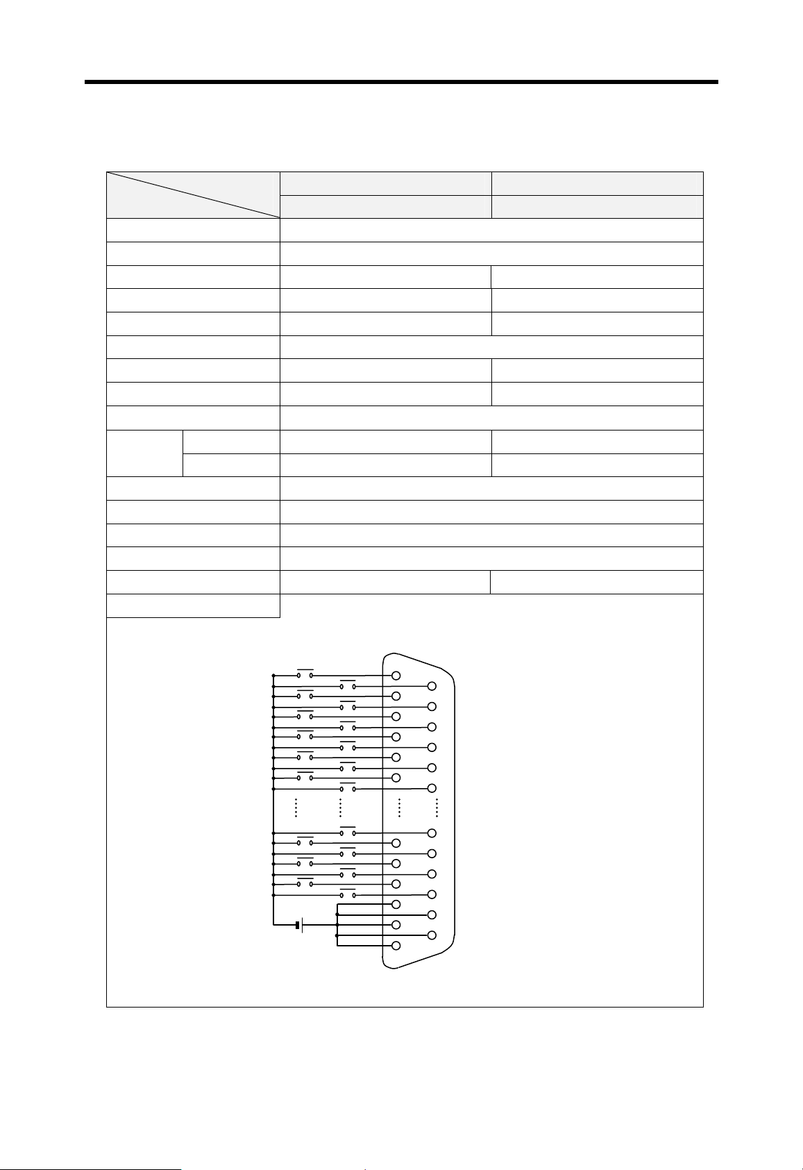
Chapter 7 I/O modules MASTER-K
7.2.6 32 points 12/24 VDC input module (source type)
K200S K300S Type
Specification
Input points 32 points
Insulation method Photo coupler insulation
Rated input voltage 24 VDC 12 / 24 VDC
Rated input current 7 mA 3 / 7 mA
Operating input voltage 20.4~28.8VDC (ripple: 5% or less) 10.24~26.4VDC (ripple: 5% or less)
Max. simultaneously on 19 points (60%)
On voltage / current 15 VDC / 4.3 mA 9.5 VDC /3.0 mA
Off voltage / current 5 VDC / 1.7 mA 5 VDC / 1.5 mA
G6I-D24B G4I-D24B
Input impedance
Response
time
Off Æ On 5 msec or less 10 msec or less
On Æ Off 5 msec or less 10 msec or less
About 3.3kΩ
Common 32 points / 1 com
Internal current consumption 75 mA
Operation indicator LED display
External wiring 37 pin D-sub connector
Weight 110 g 190 g
Wiring diagram
00
02
04
06
08
0A
01
03
05
07
09
0B
1A
1C
1E
19
1B
1D
1F
7-7
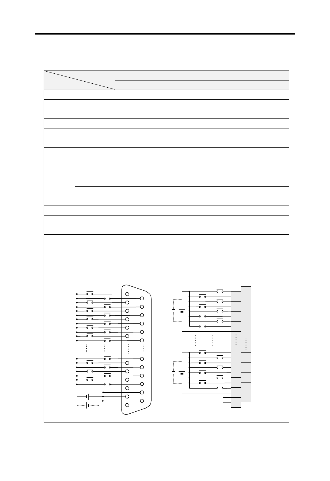
Chapter 7 I/O modules MASTER-K
A
7.2.7 32 points 24VDC input module (source/sink type)
K300S K1000S Type
Specification
Input points 32 points
Insulation method Photo coupler insulation
Rated input voltage 24 VDC
Rated input current 11mA
Operating input voltage 19.2 ~ 26.4 VDC (ripple: 5% or less )
Max. simultaneously on 19 points (60%)
On voltage / current 19.5 VDC / 4.0 mA
Off voltage / current 15 VDC / 1.0 mA
G4I-D22C G3I-D24C
Input impedance
Response
time
Off Æ On 10 m sec or less
On Æ Off 10 m sec or less
About 3.3kΩ
Common 32 points / 1 com 8 points / 1 com
Internal current consumption 70 mA 125 mA
Operation indicator LED display
External wiring 37 pin D-sub connector 38 points terminal block connector
Weight 190 g 460 g
Wiring diagram
[ G4I-D24C ] [ G3I-D24C ]
00
02
04
06
08
0A
1A
1C
1E
01
03
05
07
09
0B
19
1B
1D
1F
01
03
05
07
18
1
1C
1E
COM4
00
02
04
06
COM1
19
1B
1D
1F
N.C
N.C
2
4
6
8
28
30
32
34
36
38
1
3
5
7
9
29
31
33
35
37
7-8

Chapter 7 I/O modules MASTER-K
7.2.8 64 points 12/24VDC input module (source/sink type)
K1000S Type
Specification
Input points 64 points
Insulation method Photo coupler insulation
Rated input voltage 12 / 24 VDC
Rated input current 3 / 7 mA
Operating input voltage 10.24 ~ 26.4 VDC ( ripple: 5% or less )
Max. simultaneously on 20 points / 1COM (60%)
On voltage / current 9.5 VDC /4 mA
Off voltage / current 6 VDC / 1mA
G3I-D28A
Input impedance
Response
time
Off Æ On 10 msec or less
On Æ Off 10 msec or less
About 3.3kΩ
Common 32 points / 1 com
Internal current consumption 120 mA
Operation indicator LED display
External wiring 40-pin D-sub connector (2 connectors)
Weight 460 g
Wiring diagram
Connector 1 Connector 2
00
01
02
03
04
05
10
11
12
13
14
15
20
21
22
23
24
25
30
31
32
33
34
35
0E
0F 1F
1E
2E
2F 3F
3E
7-9

Chapter 7 I/O modules MASTER-K
K300S Type
Specification
Input points 64 points
Insulation method Photo coupler insulation
Rated input voltage 12 / 24 VDC
Rated input current 3 / 6 mA
Operating input voltage 10.2 ~ 26.4 VDC (ripple: 5% or less)
Max. simultaneously on 20 points / 1COM (60%)
On voltage / current 9.5 VDC /4mA
Off voltage / current 5 VDC / 1 mA
G4I-D28A
Input impedance
Response
time
Off Æ On 10 msec or less
On Æ Off 10 msec or less
About 5.6 kΩ
Common 32 points / 1 com
Internal current consumption 250 mA
Operation indicator LED display
External wiring 40-pin D-sub connector (2 connectors)
Weight 460 g
Wiring diagram
00/00
02/02
04/04
06/06
08/08
01
02
03
04
05 06
07 08
09 10
01/01
03/03
05/05
07/07
09/09
32/20
34/22
36/24
38/26
40/28
010302
04
05 06
07 08
09
10
33/21
35/23
37/25
39/27
41/29
28/1C
30/1E
29 30
31 32
33 34
35 36
37 38
COM1 COM1 COM2 COM2
39 40
Connector 1 (Left)
31/1D
31/1F
60/3C
62/3E
Connector 2 (Right)
29 30
31 32
33 34
35 36
37 38
39 40
7-10
61/3D
63/3F

Chapter 7 I/O modules MASTER-K
7.2.9 8 points 110VAC input module
K200S Type
Specification
Input points 8 points
Insulation method Photo coupler insulation
Rated input voltage 110VAC ( 50 / 60 Hz )
Rated input current 7 mA ( 110VAC, 60 Hz )
Operating input voltage 85 ~ 132 VAC ( 47 ~ 63 Hz )
Max. simultaneously on 8 points (100%)
Inrush current Max. 300 mA ( 0.3msec, 132 VAC )
On voltage / current 80 VAC / 5 mA
Off voltage / current 30 VAC / 2 mA
G6I-A11A
Input impedance
Response
time
Off Æ On 15 msec or less
On Æ Off 25 msec or less
About 15 kΩ
Common 8 points / 1 com
Internal current consumption 41 mA
Operation indicator LED display
External wiring
9 points terminal block connector ( M3×6 screw )
Weight 140 g
Wiring diagram
0
1
2
3
4
5
6
7
COM
110VAC
7-11

Chapter 7 I/O modules MASTER-K
A
7.2.10 16 points 110VAC input module
K300S K1000S Type
Specification
Input points 16 points
Insulation method Photo coupler insulation
Rated input voltage 100-120VAC ( 50 / 60 Hz )
Rated input current 11 mA ( 110VAC, 60 Hz )
Operating input voltage 85 ~ 132 VAC ( 50/60 Hz±3 Hz )
Max. simultaneously on 8 points / 1COM (100%)
Inrush current Max. 600 mA ( 0.3msec, 132 VAC )
On voltage / current 80 VAC / 6 mA
Off voltage / current 30 VAC / 3 mA
G4I-A12A G3I-A12A
Input impedance
Response
time
Off Æ On 15 msec or less
On Æ Off 25 msec or less
About 10 kΩ
Common 8 points / 1 com
Internal current consumption 70 mA
Operation indicator LED display
External wiring
20 points terminal block connector ( M3×6 screw )
Weight 290 g 420 g
Wiring diagram
[ G4I-A12A ] [ G3I-A12A ]
110VAC
110VAC
1
3
5
7
8
C
E
COM
0
2
4
6
COM
9
B
D
F
N.C
N.C
10
12
14
16
18
20
0
1
2
3
4
5
6
7
8
9
110VAC
11
13
110VAC
15
17
19
1
7
COM
8
9
F
COM
N.C
N.C
1
2
8
9
10
11
17
18
19
20
7-12

Chapter 7 I/O modules MASTER-K
A
7.2.11 32 points 110VAC input module
K1000S Type
Specification
Input points 32 points
Insulation method Photo coupler insulation
Rated input voltage 110 VAC ( 50 / 60 Hz )
Rated input current 11 mA ( 110 VAC, 60 Hz )
Operating input voltage 85 ~ 132 VAC ( 47 ~ 63 Hz )
Max. simultaneously on 5 points / 1COM ( 60% )
Inrush current Max. 300 mA ( 0.3msec, 132 VAC )
On voltage / current 80 VAC / 6 mA
Off voltage / current 30 VAC / 3 mA
G3I-A14A
Input impedance
Response
time
Off Æ On 15 msec or less
On Æ Off 25 msec or less
About 10 kΩ
Common 8 points / 1 com
Internal current consumption 120 mA
Operation indicator LED display
External wiring
38 points terminal block connector ( M3×6 screw )
Weight 560 g
Wiring diagram
00
01
02
110VAC
110VAC
03
05
07
18
1
1C
1E
COM4
04
06
COM1
19
1B
1D
1F
N.C
N.C
2
4
6
8
28
30
32
34
36
38
1
3
5
7
9
29
31
33
35
37
7-13

Chapter 7 I/O modules MASTER-K
7.2.12 8 points 220VAC input module
K200S Type
Specification
Input points 8 points
Insulation method Photo coupler insulation
Rated input voltage 200 ~ 240 VAC (50 / 60 Hz)
Rated input current 11 mA (220VAC, 60 Hz)
Operating input voltage 170 ~ 264 VAC (50/ 60±3Hz )
Max. simultaneously on 8 points (100%)
Inrush current Max. 600 mA ( 0.12msec, 264 VAC )
On voltage / current 80 VAC / 5 mA
Off voltage / current 30 VAC / 2 mA
G6I-A21A
Input impedance
Response
time
Off Æ On 15 msec or less
On Æ Off 25 msec or less
About 20 kΩ
Common 8 points / 1 com
Internal current consumption 40 mA
Operation indicator LED display
External wiring
9 points terminal block connector ( M3×6 screw )
Weight 140 g
Wiring diagram
0
1
2
3
4
5
6
7
COM
220VAC
7-14

Chapter 7 I/O modules MASTER-K
A
7.2.13 16 points 220VAC input module
K300S K1000S Type
Specification
Input points 16 points
Insulation method Photo coupler insulation
Rated input voltage 220~240 VAC (50 / 60 Hz)
Rated input current 11 mA (220VAC/ 60 Hz)
Operating input voltage 170 ~ 264 VAC (50 ~ 60±3 Hz)
Max. simultaneously on 8 points / 1COM (100%)
Inrush current Max. 600 mA ( 0.12msec, 264 VAC )
On voltage / current 80 VAC / 6 mA
Off voltage / current 30 VAC / 3 mA
G4I-A22A G3I-A22A
Input impedance
Response
time
Off Æ On 15 msec or less
On Æ Off 25 msec or less
About 10 kΩ
Common 8 points / 1 com
Internal current consumption 70 mA
Operation indicator LED display
External wiring
20 points terminal block connector (M3×6 screw)
Weight 300 g 420 g
Wiring diagram
[ G4I-A22A ] [ G3I-A22A ]
220VAC
220VAC
1
3
5
7
8
C
E
COM
0
2
4
6
COM
9
B
D
F
N.C
N.C
10
12
14
16
18
20
0
1
2
3
4
5
6
7
8
9
220VAC
11
13
220VAC
15
17
19
1
7
COM
8
9
F
COM
N.C
N.C
1
2
8
9
10
11
17
18
19
20
7-15

Chapter 7 I/O modules MASTER-K
A
7.2.14 32 points 220VAC input module
K1000S Type
Specification
Input points 32 points
Insulation method Photo coupler insulation
Rated input voltage 220 VAC ( 50 / 60 Hz )
Rated input current 10 mA ( 220 VAC, 60 Hz )
Operating input voltage 170 ~ 264 VAC ( 47 ~ 63 Hz )
Max. simultaneously on 5 points / 1COM ( 60% )
Inrush current Max. 600 mA ( 0.12msec, 264 VAC )
On voltage / current 150 VAC / 6 mA
Off voltage / current 30 VAC / 3 mA
G3I-A24A
Input impedance
Response
time
Off Æ On 15 msec or less
On Æ Off 25 msec or less
About 10 kΩ
Common 8 points / 1 com
Internal current consumption 120 mA
Operation indicator LED display
External wiring
38 points terminal block connector ( M3×6 screw )
Weight 560 g
Wiring diagram
00
01
02
220VAC
220VAC
03
05
07
18
1
1C
1E
COM4
04
06
COM1
19
1B
1D
1F
N.C
N.C
2
4
6
8
28
30
32
34
36
38
1
3
5
7
9
29
31
33
35
37
7-16
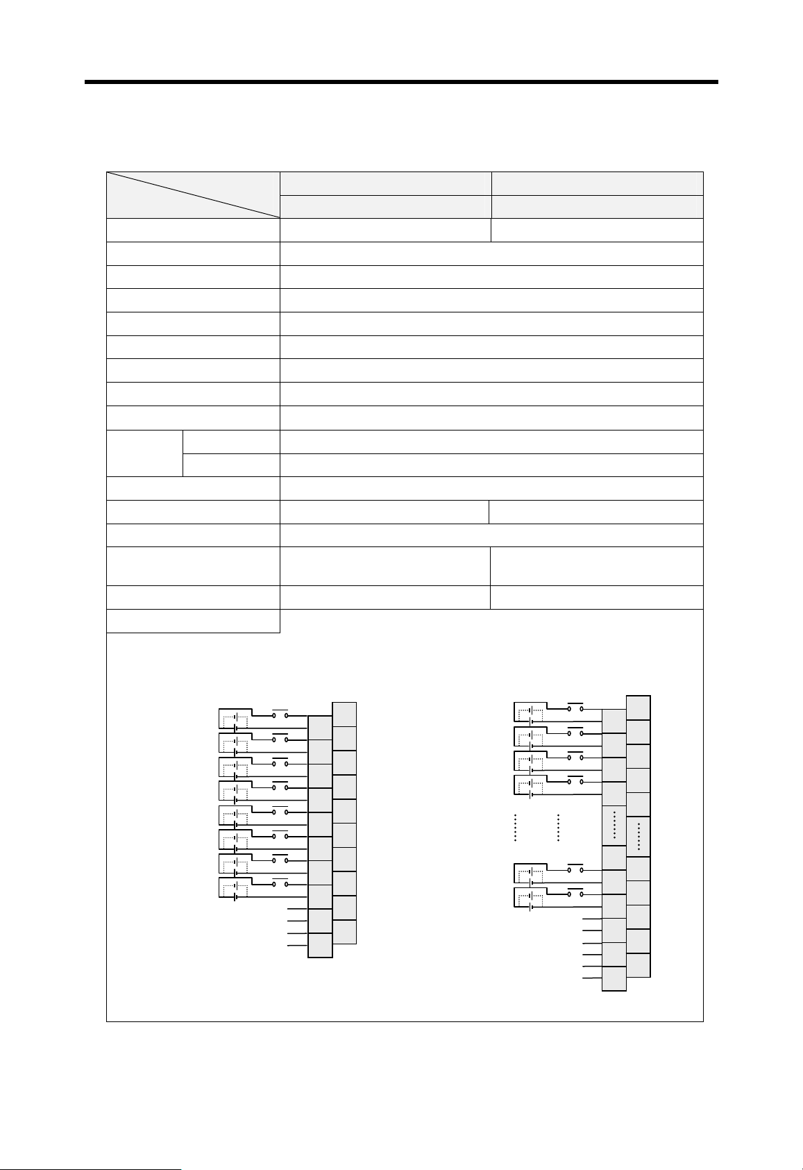
Chapter 7 I/O modules MASTER-K
7.2.15 Interrupt input module
K300S K1000S Type
Specification
Input points 8 points 16 points
Insulation method Photo coupler insulation
Rated input voltage 24 VDC
Rated input current 10 mA
Operating input voltage 21.6 ~ 26.4 VDC
Max. simultaneously on 1 points / 1COM (100%)
On voltage / current 15 VAC / 6.5 mA
Off voltage / current 5 VDC / 2 mA
G4F-INTA G3F-INTA
Input impedance
Response
time
Common 1 points / 1 com
Internal current consumption 65 mA 200 mA
Operation indicator LED display
External wiring
Weight 160 g 400 g
Wiring diagram
[ K4F-INTA ] [ K7F-INTA ]
Off Æ On 0.5 msec or less
On Æ Off 0.5 msec or less
About 2.4 kΩ
20 points terminal block connector
( M3×6 screw )
00
01
02
03
04
05
06
07
N.C
N.C
N.C
N.C
2
4
6
8
10
12
14
16
18
20
1
3
5
7
9
11
13
15
17
19
38 points terminal block connector
( M3×6 screw )
00
01
02
03
14
15
N.C
N.C
N.C
N.C
N.C
N.C
2
4
6
8
28
30
32
34
36
38
1
3
5
7
9
29
31
33
35
37
7-17

Chapter 7 I/O modules MASTER-K
7.3 Digital output modules
7.3.1 8 points relay output module
K200S Type
Item
Output points 8 points
Insulation method Photo coupler
G6Q-RY1A
Rated load voltage / current
24 VDC / 2A (resistive load), 220 VAC / 2A (cosψ = 1)
Minimum load voltage / current 5 VDC / 1mA
Maximum load voltage 125 VDC / 250 VAC
Leakage current 0.1 mA ( 220 VAC, 60Hz )
Maximum switching frequency 3,600 times / hour
Surge absorber None
Mechanical No load Over 20 million times
Rated voltage / current Over 0.1 million times
Lifetime of
contact
Electrical
200VAC / 1.5A, 240VAC / 1A (cosψ = 0.7)
200VAC / 1A, 240VAC / 0.5A (cosψ = 0.35)
24VDC / 1A, 100VDC / 0.1A (L / R = 7ms) Over 0.1 million times
Off Æ On 10msec or less
Response time
On Æ Off 12msec or less
Common method 1 point / 1COM (Independent common)
Internal current consumption 210mA (when all outputs are on)
Operation indicator LED
External wiring
18 points terminal block connector ( M3×6 screw)
Weight 160 g
Wiring diagram
Over 0.1 million times
Over 0.1 million times
00
L
01
02
03
04
05
06
07
L
N.C
N.C
7-18
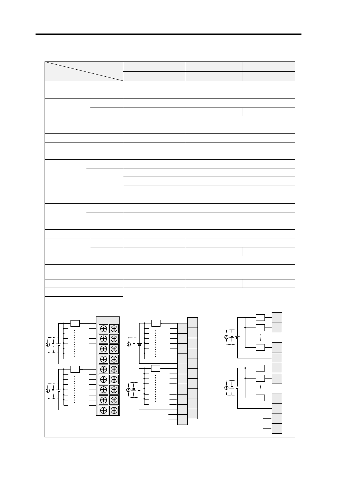
Chapter 7 I/O modules MASTER-K
A
7.3.2 16 points relay output module
K200S K300S K1000S Type
Item
Output points 16 points
Insulation method Photo coupler
Rated load
voltage / current
Per 1 point
Per 1 COM 5A / 1COM 4A / 1COM 8A / 1COM
Minimum load voltage/current 5 VDC / 1mA
Maximum load voltage 110 VDC / 250 VAC 125 VDC / 250 VAC
Leakage current 0.1 mA ( 220 VAC, 60Hz )
Maximum switching frequency 1,200 times / hour 3,600 times / hour
Surge absorber None
Mechanical No load Over 20 million times
Lifetime of
contact
Response time
Electrical
Off Æ On 10 msec or less
On Æ Off 12 msec or less
Common method 8 point / 1COM
Internal current consumption 400mA (all outputs on) 100mA (when all outputs are on)
External power
supply
Voltage None
Current None Max. 100mA Max. 150 mA
Operation indicator LED
External wiring
Weight 190 g 310 g 460 g
Wiring diagram
[ G6Q-RY2A ] [ G4Q-RY2A ] [ G3Q-RY2A ]
G3Q-RY2A G4Q-RY2A G3Q-RY2A
24 VDC / 2A (resistive load), 220 VAC / 2A (cosψ = 1)
Rated voltage / current Over 0.1 million times
200VAC / 1.5A, 240VAC / 1A (cosψ = 0.7)
200VAC / 1A, 240VAC / 0.5A (cosψ = 0.35)
Over 0.1 million times
Over 0.1 million times
24VDC / 1A, 100VDC / 0.1A (L / R = 7ms) Over 0.1 million times
24 VDC ± 10% ( ripple : 4 Vp-p or less )
18 points terminal block
connector
20 points terminal block connector
0
L
00
L
01
02
03
04
05
06
07
08
L
09
0A
0B
0C
0D
0E
0F
00
L
01
02
03
04
05
06
07
08
L
09
0
0B
0C
0D
0E
0F
N.C
N.C
2
4
6
8
10
12
14
16
18
20
1
3
5
7
9
11
13
15
17
19
1
7
COM1
8
9
F
COM2
N.C
N.C
1
L
2
L
8
9
L
10
L
11
L
17
18
19
20
7-19
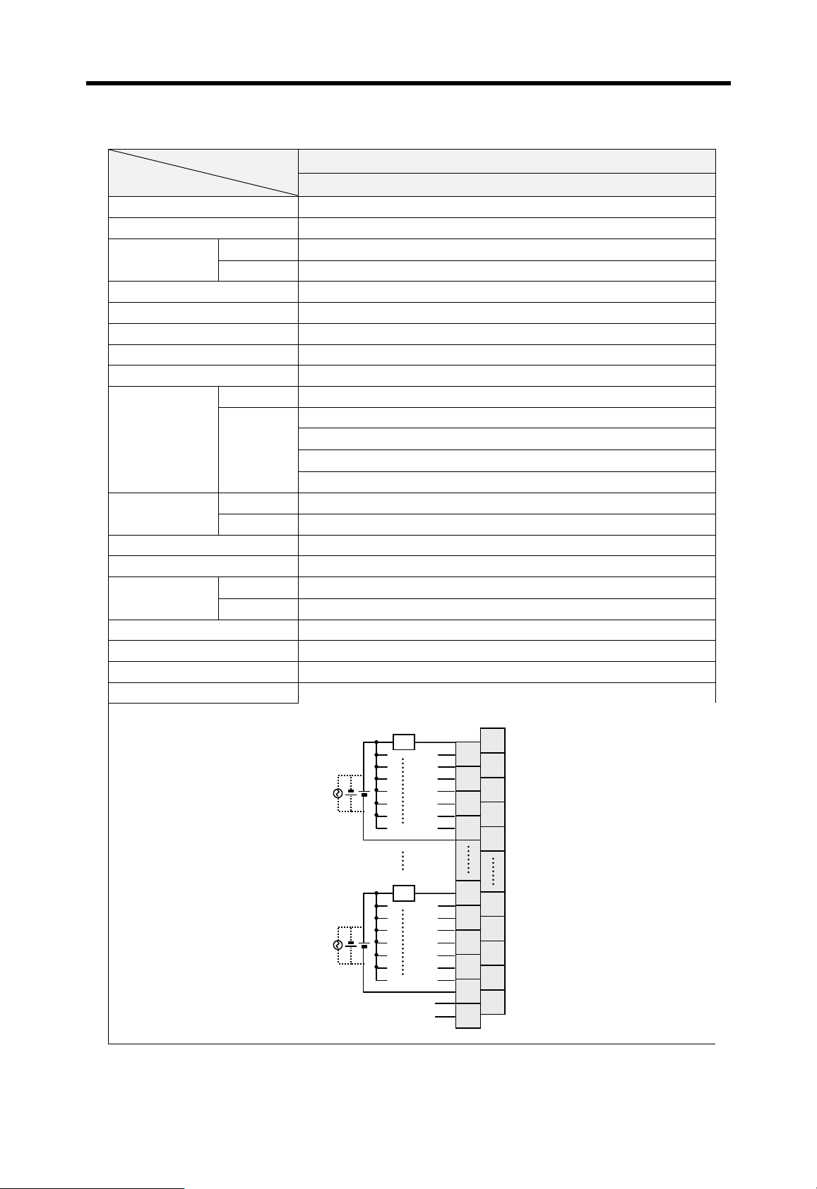
Chapter 7 I/O modules MASTER-K
A
7.3.3 32 points relay output module
K1000S Type
Item
Output points 32 points
Insulation method Photo coupler
Rated load
voltage / current
Per 1 point
Per 1 COM 5A / 1COM
24 VDC / 2A (resistive load), 220 VAC / 2A (cosψ = 1)
Minimum load voltage / current 5 VDC / 1mA
Maximum load voltage 125 VDC / 250 VAC
Leakage current 0.1 mA ( 220 VAC, 60Hz )
Maximum switching frequency 3,600 times / hour
Surge absorber None
Mechanical No load Over 20 million times
Rated voltage / current Over 0.1 million times
Lifetime of
contact
Electrical
200VAC / 1.5A, 240VAC / 1A (cosψ = 0.7)
200VAC / 1A, 240VAC / 0.5A (cosψ = 0.35)
24VDC / 1A, 100VDC / 0.1A (L / R = 7ms) Over 0.1 million times
Response time
Off Æ On 10 msec or less
On Æ Off 12 msec or less
Common method 8 point / 1COM
Internal current consumption 200mA (when all outputs are on)
External power
supply
Voltage
Current Max. 170 mA
24 VDC ± 10% ( ripple : 4 Vp-p or less )
Operation indicator LED
External wiring 38 points terminal block connector
Weight 550 g
Wiring diagram
00
L
01
02
03
04
05
06
07
G3Q-RY4A
1
2
3
4
5
6
7
8
9
Over 0.1 million times
Over 0.1 million times
18
L
N.C
N.C
19
1
1B
1C
1D
1E
1F
28
30
32
34
36
38
29
31
33
35
37
7-20
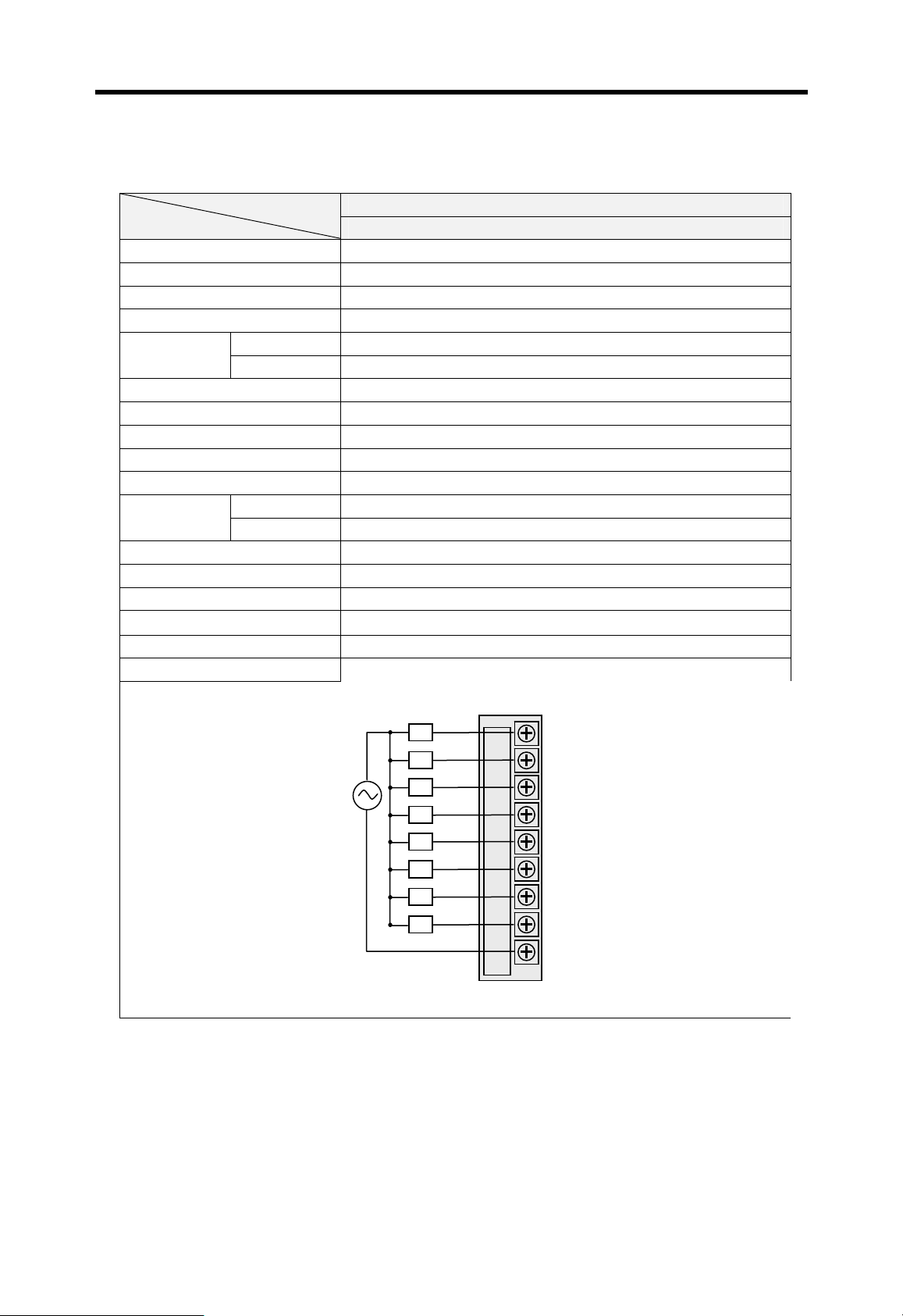
Chapter 7 I/O modules MASTER-K
7.3.4 8 points triac output module
K200S Type
Item
Output points 8 points
Insulation method Photo coupler
Rated load voltage 100 ~ 240 VAC ( 50 / 60 Hz )
Maximum load voltage 264 VAC
Maximum load
current
Per 1point 1 A
Per 1 COM 4 A
Minimum load current 20 mA
Leakage current 2.5 mA ( 220 VAC, 60Hz )
Maximum inrush current 40 A, ( 10 msec or less )
On state voltage drop 2.5 VAC or less ( 2 A)
Surge absorber Varistor (387 ~ 473 V), C-R absorber
Response time
Off Æ On 1 msec or less
On Æ Off 1/2 cycle + 1 msec or less
Common method 8 point / 1COM
Internal current consumption 210 mA (when all outputs are on)
Operation indicator LED
External wiring
9 points terminal block connector ( M3×6 screw)
Weight 160 g
Wiring diagram
G6Q-SS1A
00
L
01
100 ~ 240 VAC
L
02
L
03
L
04
L
05
L
06
L
07
L
7-21

Chapter 7 I/O modules MASTER-K
7.3.5 16 points triac output module
K300S K1000S Type
Item
Output points 16 points
Insulation method Photo coupler
Rated load voltage 100 ~ 240 VAC (50 / 60 Hz )
Maximum load voltage 264 VAC
Maximum load
current
Per 1point 1 A 0.6 A 2 A
Per 1 COM 5 A 2.4 A 5 A
Minimum load current 20mA 10mA 20mA
Leakage current 2.5 mA ( 220 VAC, 60Hz )
Maximum inrush current 25A, 10msec or less 20A, 10msec or less 40A, 10msec or less
On state voltage drop 1.5 VAC or less (1A) 1.5VAC or less (0.6A) 1.5VAC or less (2A)
Surge absorber Varistor (387 ~ 473 V), C-R absorber
Response time
Off Æ On 1/2 cycle + 1 msec or less
On Æ Off 1/2 cycle + 1 msec or less
Common method 8 points / 1COM
Internal current consumption 330 mA (when all outputs are on)
Operation indicator LED
External wiring
Weight 350 g 500 g
Wiring diagram
[ G4Q-SS2A & G4Q-SS2B ] [ G3Q-SS2A ]
G4Q-SS2A G4Q-SS2B G3Q-SS2A
20 points terminal block connector (M3×6 screw)
100 ~ 240VAC
100 ~ 240VAC
0
1
7
COM1
8
9
F
COM2
N.C
N.C
L
1
L
2
L
8
9
L
10
L
11
L
17
18
19
20
00
L
01
02
03
04
05
06
07
08
L
09
0A
0B
0C
0D
0E
0F
N.C
N.C
2
4
6
8
10
12
14
16
18
20
11
13
15
17
19
1
3
100 ~ 240VAC
5
7
9
100 ~ 240VAC
7-22

Chapter 7 I/O modules MASTER-K
A
7.3.6 32 points triac output module
K1000S Type
Item
Output points 32 points
Insulation method Photo coupler
Rated load voltage 100 ~ 240 VAC ( 50 / 60 Hz )
Maximum load voltage 264 VAC
Maximum load
current
Per 1point 1 A
Per 1 COM 5 A
Minimum load current 20 mA
Leakage current 2.5 mA ( 220 VAC, 60Hz )
Maximum inrush current 25 A, ( 10 msec or less )
On state voltage drop 1.5 VAC or less ( 1 A)
Surge absorber Varistor (387 ~ 473 V), C-R absorber
Response time
Off Æ On 1 msec or less
On Æ Off 1/2 cycle + 1 msec or less
Common method 8 point / 1COM
Internal current consumption 600 mA (when all outputs are on)
Operation indicator LED
External wiring
38 points terminal block connector ( M3×6 screw)
Weight 600 g
Wiring diagram
G3Q-SS4A
00
L
01
02
100 ~ 240VAC
100 ~ 240VAC
03
04
05
06
07
18
L
19
1
1B
1C
1D
1E
1F
N.C
N.C
2
4
6
8
28
30
32
34
36
38
1
3
5
7
9
29
31
33
35
37
7-23

Chapter 7 I/O modules MASTER-K
A
7.3.7 16 points transistor output module (sink type)
K200S K300S K1000S Type
Item
Output points 16 points
Insulation method Photo coupler
Rated load voltage 12 / 24 VDC
Maximum load
current
Per 1 point 0.5 A / 1 point 2 A / 1 point
Per 1 COM 5 A / 1COM 4 A / 1COM 8 A / 1COM
Leakage current 0.1 mA
Maximum inrush current 4 A, 10 msec or less 8 A, 10 msec or less
On state voltage drop 1.5 VDC or less
Surge absorber Clamp diode Varistor Clamp diode
Response time
Off Æ On 2 msec or less
On Æ Off 2 msec or less
Common method 16 point / 1COM 8 point / 1COM
Internal current consumption
External power
supply
Voltage
Current Max. 48mA per 1com Max. 100mA per 1com
Operation indicator LED
External wiring
Weight 180 g 270 g 540 g
Wiring diagram
[ G6Q-TR2A ] [G4Q-TR2A ] [G3Q-TR2A ]
G6Q-TR2A G4Q-TR2A G3Q-TR2A
180mA
(all outputs are on)
1 10mA
(all outputs are on)
120mA
(all outputs are on)
24 VDC ± 10% ( ripple : 4 Vp-p or less )
18 points terminal
block connector
20 points terminal block connector
0
L
00
L
01
02
03
04
05
06
07
08
09
0A
0B
0C
0D
0E
0F
L
00
01
02
03
04
05
06
07
08
09
0
0B
0C
0D
0E
0F
2
4
6
8
10
12
14
16
18
11
13
15
17
19
1
1
3
5
7
7
9
8
9
F
20
1
L
2
L
8
9
10
L
11
L
12
L
18
19
20
7-24
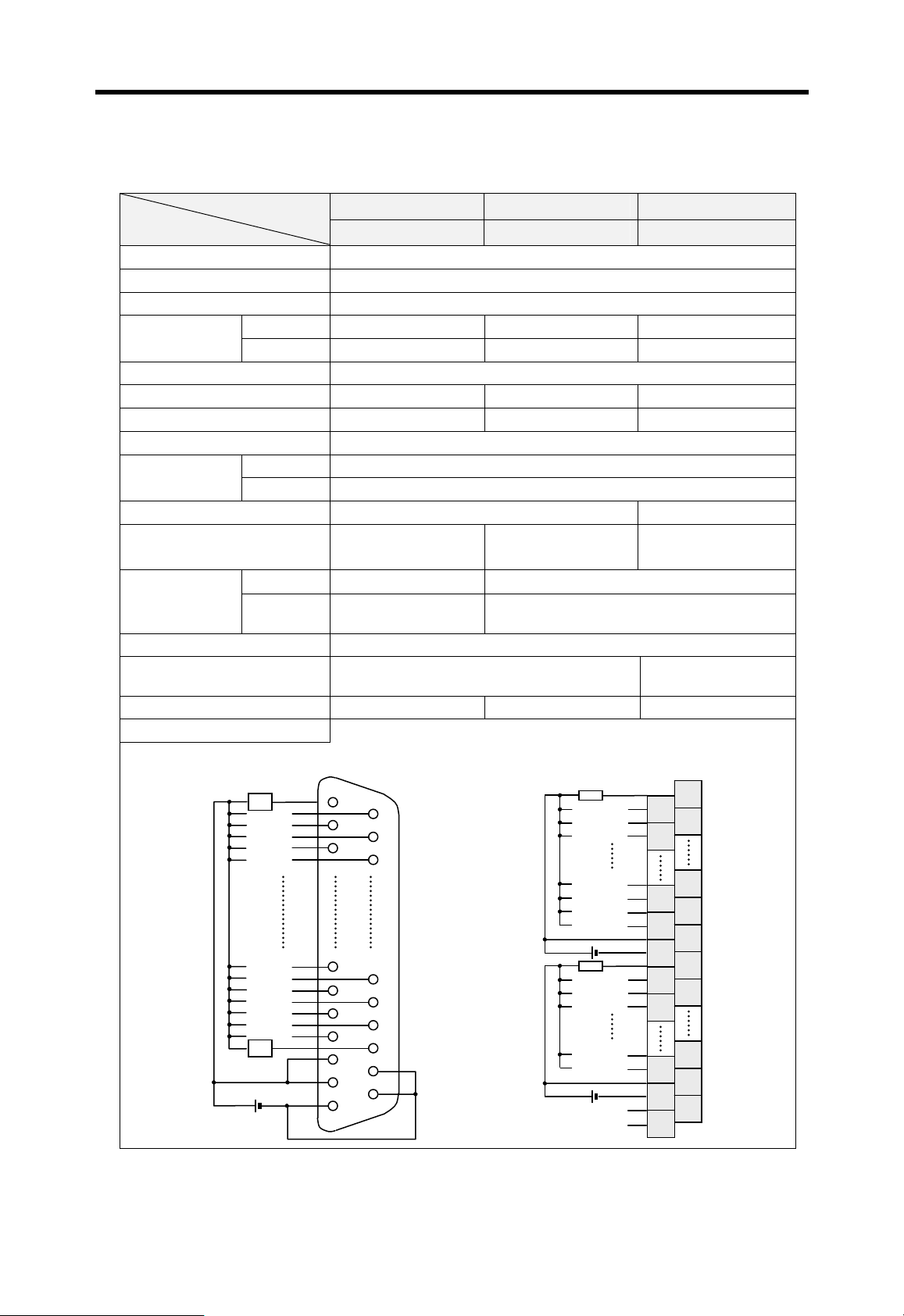
Chapter 7 I/O modules MASTER-K
7.3.8 32 points transistor output module (sink type)
K200S K300S K1000S Type
Item
Output points 32 points
Insulation method Photo coupler
Rated load voltage 12 / 24 VDC
Maximum load
current
Per 1 point 0.1 A / 1 point 0.1 A / 1 point 0.5 A / 1 point
Per 1 COM 2 A / 1COM 2 A / 1COM 3 A / 1COM
Leakage current 0.1 mA
Maximum inrush current 0.4 A, 10 msec or less 4 A, 10 msec or less 4 A, 10 msec or less
On state voltage drop 2.0 VDC or less 1.0 VDC or less 1.5 VDC or less
Surge absorber Clamp diode
Response time
Off Æ On 2 msec or less
On Æ Off 2 msec or less
Common method 32 point / 1COM 16 point / 1COM
Internal current consumption
External power
supply
Voltage 10.2 ~ 26.4 VDC
Current
Operation indicator LED
External wiring 32 Pin D-sub connector
Weight 110 g 180 g 500 g
Wiring diagram
[ G6Q-TR4A & G4Q-TR4A ] [ G3Q-TR4A ]
G6Q-TR4A G4Q-TR4A G3Q-TR4A
180mA
(all outputs are on)
1 10mA
(all outputs are on)
120mA
(all outputs are on)
24 VDC ± 10% ( ripple : 4 Vp-p or less )
Max. 36mA per
1com
Max. 150mA per 1com
38 points terminal
block connector
00
L
01
02
03
04
05
18
19
1A
1B
1C
1D
1E
1F
L
00
01
02
03
0C
0D
0E
0F
10
11
12
13
1E
1F
N.C
N.C
2
4
14
16
18
20
22
34
36
38
1
3
13
15
17
19
21
33
35
37
7-25

Chapter 7 I/O modules MASTER-K
7.3.9 64 points transistor output module (sink type)
K1000S Type
Item
Output points 64 points
Insulation method Photo coupler
Rated load voltage 12 / 24 VDC
Operating load voltage 10.2 ~ 26.4 VDC
Maximum load
current
Per 1 point 0.1 A / 1 point
Per 1 COM 2 A / 1COM
Leakage current 0.1 mA
Maximum inrush current 0.4 A,/10 msec or less
On state voltage drop 1.0 VDC or less
Surge absorber None
Response time
Off Æ On 2 msec or less
On Æ Off 2 msec or less
Common method 32 point / 1COM
Internal current consumption 250mA (all outputs are on)
External power
supply
Voltage 10.2 ~ 26.4 VDC
Current 170mA or less (24VDC/1 Com )
Operation indicator LED
External wiring 40 pin D-sub connector (2 connectors)
Weight 400 g
Wiring diagram
[ Connector 1 ] [ Connector 2 ]
G3Q-TR8A
00
01
02
03
04
05
0E
0F
L
L
L
L
L
L
L
L
10
L
11
L
12
L
13
L
14
L
15
L
1E
L
1F
L
20
21
22
23
24
25
2E
2F
L
L
L
L
L
L
L
L
30
L
31
L
32
L
33
L
34
L
35
L
3E
L
3F
L
7-26

Chapter 7 I/O modules MASTER-K
K300S Type
Item
Output points 64 points
Insulation method Photo coupler
Rated load voltage 12 / 24 VDC
Operating load voltage 10.2 ~ 26.4 VDC
Maximum load
current
Per 1 point 0.1 A / 1 point
Per 1 COM 2 A / 1COM
Leakage current 0.1 mA
Maximum inrush current 0.4 A, 10 msec or less
On state voltage drop 1.0 VDC or less
Surge absorber None
Response time
Off Æ On 2 msec or less
On Æ Off 2 msec or less
Common method 32 point / 1COM
Internal current consumption 250mA (all outputs are on)
External power
supply
Voltage 10.2 ~ 26.4 VDC
Current Max. 100mA per 1com ( 24VDC )
Operation indicator LED
External wiring 40 Pin D-sub connector ( 2 connectors )
Weight 400 g
Wiring diagram
G4Q-TR8A
00/00
L L
02/02
L
04/04
L
06/06
L
08/08
L
01
02
03
04
05 06
07 08
09 10
01/01
03/03
L
05/05
L
07/07
L
09/09
L
32/20
L L
34/22
L
36/24
L
38/26
L
40/28
L
010302
04
05 06
07 08
09
10
33/21
35/23
L
37/25
L
39/27
L
41/29
L
28/1C
L
30/1E
29 30
L
31 32
33 34
35 36
37 38
COM1 COM1 COM2 COM2
39 40
Connector 1 (Left)
31/1D
L
31/1F
L
60/3C
62/3E
L
29 30
L
31 32
61/3D
L
63/3F
L
33 34
35 36
37 38
39 40
Connector 2 (Right)
7-27

Chapter 7 I/O modules MASTER-K
A
7.3.10 16 points transistor output module (source type)
K200S K300S Type
Item
Output points 16 points
Insulation method Photo coupler
Rated load voltage 12 / 24 VDC
Operating load voltage 10.2 ~ 26,4 VDC
Maximum load
current
Per 1 point 0.5 A / 1 point
Per 1 COM 4 A / 1COM 3 A / 1COM
Leakage current 0.1 mA
Maximum inrush current 4 A, 10 msec or less
On state voltage drop 1.5 VDC or less
Surge absorber Clamp diode Varistor
Response time
Off Æ On 2 msec or less
On Æ Off 2 msec or less
Common method 16 point / 1COM 8 point / 1COM
Internal current consumption 180mA (all outputs are on) 110mA (all outputs are on)
External power
supply
Voltage
Current Max. 48mA per 1com Max. 100mA per 1com
24 VDC ± 10% ( ripple : 4 Vp-p or less )
Operation indicator LED
External wiring 18 points terminal block connector 20 points terminal block connector
Weight 180 g 270 g
Wiring diagram
[ G6Q-TR2B ] [ G4Q-TR2B ]
G6Q-TR2B G4Q-TR2B
00
L
01
02
03
04
05
06
07
08
09
0A
0B
0C
0D
0E
0F
00
01
02
03
04
05
06
07
08
09
0
0B
0C
0D
0E
0F
2
4
6
8
10
12
14
16
18
1
3
5
7
9
11
13
15
17
19
20
7-28

Chapter 7 I/O modules MASTER-K
7.3.11 32 points transistor output module (source type)
K200S K300S K1000S Type
Item
Output points 32 points
Insulation method Photo coupler
Rated load voltage 12 / 24 VDC
Maximum load
current
Per 1 point 0.1 A / 1 point 0.1 A / 1 point 0.5 A / 1 point
Per 1 COM 2 A / 1COM 2 A / 1COM 3 A / 1COM
Leakage current 0.1 mA
Maximum inrush current 0.4 A, 10 msec or less 4 A, 10 msec or less 4 A, 10 msec or less
On state voltage drop 2.0 VDC or less 1.0 VDC or less 1.5 VDC or less
Surge absorber Clamp diode
Response time
Off Æ On 2 msec or less
On Æ Off 2 msec or less
Common method 32 point / 1COM 16 point / 1COM
Internal current consumption
External power
supply
Voltage 10.2 ~ 26.4 VDC
Current
Operation indicator LED
External wiring 32 Pin D-sub connector
Weight 110 g 180 g 500 g
Wiring diagram
[ G6Q-TR4B & G4Q-TR4B ] [ G3Q-TR4B ]
G6Q-TR4B G4Q-TR4B G3Q-TR4B
180mA
(all outputs are on)
1 10mA
(all outputs are on)
120mA
(all outputs are on)
24 VDC ± 10% ( ripple : 4 Vp-p or less )
Max. 36mA per
1com
Max. 150mA per 1com
38 points terminal
block connector
00
L
01
02
03
04
05
18
19
1A
1B
1C
1D
1E
1F
L
00
01
02
03
0C
0D
0E
0F
10
11
12
13
1E
1F
N.C
N.C
2
4
14
16
18
20
22
34
36
38
1
3
13
15
17
19
21
33
35
37
7-29

Chapter 7 I/O modules MASTER-K
7.3.12 64 points transistor output module (source type)
K1000S Type
Item
Output points 64 points
Insulation method Photo coupler
Rated load voltage 12 / 24 VDC
Operating load voltage 10.2 ~ 26.4 VDC
Maximum load
current
Per 1 point 0.1 A / 1 point
Per 1 COM 2 A / 1COM
Leakage current 0.1 mA
Maximum inrush current 0.4 A, 10 msec or less
On state voltage drop 1.0 VDC or less
Surge absorber None
Response time
Off Æ On 2 msec or less
On Æ Off 2 msec or less
Common method 32 point / 1COM
Internal current consumption 300mA (all outputs are on)
External power
supply
Voltage 10.2 ~ 26.4 VDC
Current Max. 100mA per 1com ( 24VDC )
Operation indicator LED
External wiring 40 Pin D-sub connector ( 2 connectors )
Weight 420 g
Wiring diagram
[ Connector 1 ] [ Connector 2 ]
G3Q-TR8B
00
01
02
03
04
05
0E
0F
L
L
L
L
L
L
L
L
10
L
11
L
12
L
13
L
14
L
15
L
1E
L
1F
L
20
21
22
23
24
25
2E
2F
L
L
L
L
L
L
L
L
30
L
31
L
32
L
33
L
34
L
35
L
3E
L
3F
L
7-30

Chapter 7 I/O modules MASTER-K
A
7.4 Digital input / output hybrid modules
7.4.1 8 points 12/24VDC input + 8 points relay output
K200S
G6H-DR2A
Input Output
Input point 8 points Output points 8 points
Insulation method Photo coupler insulation Insulation method Relay insulation
Rated input voltage DC12 / 24V Rated load voltage / current
Rated input current 3 / 7 mA Min. load voltage / current DC5V / 1 mA
Operating voltage DC10.2~26.4V Max. load voltage / current AC250V, DC125V
Max. simultaneously
on
100% simultaneously on Leakage current 0.1 mA (AC220V, 60Hz)
On voltage / current 9.5 VDC / 3.0 mA Max. switching frequency 1.200 times / hour
Off voltage / current 5 VDC / 1.5 mA Surge absorber None
24 VDC / 2A (resistive load),
220 VAC / 2A (cosψ = 1)
Input impedance
Respo
Off Æ On 5 ms or less
About 3.3 kΩ
Lifetime of
contact
Mechanical
Same as G6Q-RY2A
Electrical
nse
time
Common
On Æ Off
7 ms or less
8 points / 1COM
Response
time
Off → On
On → Off
10 ms or less
12 ms or less
- - Common 8 points / 1COM
Operation Indicator LED
External wiring 18 points terminal block connector (M3×6 scre w)
Internal current
consumption
250 mA
Weight 0.20 kg
Wiring
0
1
2
3
4
5
6
7
08
L
09
0
0B
0C
0D
0E
0F
7-31

Chapter 7 I/O modules MASTER-K
A
K300S
G4H-DR2A
Input Output
Input point 8 points Output points 8 points
Insulation method Photo coupler insulation Insulation method Photo cou pler insulation
Rated input voltage 12 / 24VDC Rated load voltage / current
Rated input current 5 / 11 mA Min. load voltage / current DC5V / 1 mA
Operating voltage 10.2~26.4VDC Max. load voltage / current AC250V, DC125V
Max. simultaneously
on
100% simultaneously on Leakage current 0.1 mA (AC220V, 60Hz)
On voltage / current 9.5 VDC / 4.0 mA Max. switching frequency 1,200 times / hour
Off voltage / current 6 VDC / 1.0 mA Surge absorber None
24 VDC / 2A (resistive load),
220 VAC / 2A (cosψ = 1)
Input impedance
Respo
Off Æ On 10 ms or less
About 2.2 kΩ
Lifetime of
contact
Mechanical
Same as G4Q-RY2A
Electrical
nse
time
Common
On Æ Off
10 ms or less
8 points / 1COM
Response
time
Off → On
On → Off
10 ms or less
12 ms or less
- - Common 8 points / 1COM
- - Voltage DC24V±10%
External
power
- -
supply
Current 45 mA
Operation Indicator LED
External wiring 20 points terminal block connector (M3×6 scre w)
Internal current
consumption
100 mA
Weight 0.26 kg
Wiring
0
1
2
3
4
5
6
7
COM
08
L
09
0
0B
0C
0D
0E
0F
N.C
N.C
2
4
6
8
10
12
14
16
18
20
1
3
5
7
9
11
13
15
17
19
7-32
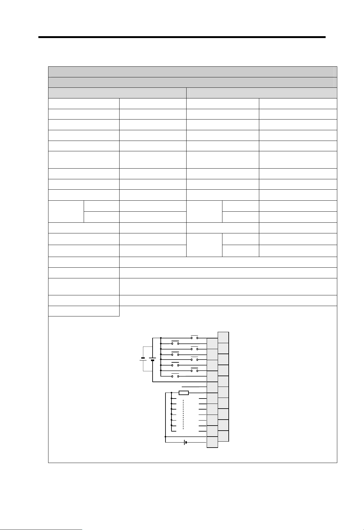
Chapter 7 I/O modules MASTER-K
A
7.4.2 8 points 12/24VDC input + 8 points transistor output
K300S
G4H-DT2A
Input Output
Input point 8 points Output points 8 points
Insulation method Photo coupler insulation Insulation method Photo coupler insulation
Rated input voltage DC12 / 24V Rated load voltage DC12 / 24V
Rated input current 5 / 11 mA Operating load voltage DC10.2 ~ 26.4V
Operating voltage DC10.2~26.4V Max. load current 0.5A / 1 point, 3A / 1COM
Max. simultaneously on
On voltage / current 9.5 VDC / 4.0 mA Max. inrush current 4A / 10ms or less
Off voltage / current 5 VDC / 1.0 mA On state voltage drop 1.5 VDC or less
100% simultaneously
on
Leakage current 0.1 mA (AC220V, 60Hz)
Input impedance
Response
time
Off Æ On 10 ms or less
On Æ Off 10 ms or less
About 2.2 kΩ
Surge absorber Varistor
Response
time
Off → On
On → Off
2 ms or less
2 ms or less
Common 8 points / 1COM Common 8 points / 1COM
- - Voltage DC24V±10%
External
power
- -
supply
Current 50 mA
Operation Indicator LED
External wiring 20 points terminal block connector (M3×6 screw)
Internal current
consumption
100 mA
Weight 0.26 kg
Wiring
N.C
0
2
4
6
COM
08
09
0
0B
0C
0D
0E
0F
1
3
5
7
2
4
6
8
10
12
14
16
18
1
3
5
7
9
11
13
15
17
19
20
7-33

Chapter 8 Power supply modules
8 Power supply modules............................................................................. 8-1
8.1 Selection of power supply module ......................................................................... 8-1
8.1.1 K200S.................................................................................................................... 8-1
8.1.2 K300S.................................................................................................................... 8-2
8.1.3 K1000S.................................................................................................................. 8-3
8.2 Specifications............................................................................................................ 8-4
8.2.1 K200S series..........................................................................................................8-4
8.2.2 K300S series..........................................................................................................8-5
8.2.3 K1000S series........................................................................................................8-5
8.3 Parts names and descriptions.................................................................................8-6

Chapter 8 Power supply modules MASTER-K
8 Power supply modules
In this chapter, it will be de scribed that the power supply modules of MASTER-K series.
8.1 Selection of power supply module
When select a power supply module of PLC system, it should be considered that the total
current consumption of CPU module, digital I/O modules, special purpose modules, and
communication modules. If the power capacity of power supply module is smaller than the total
current consumption of PLC system, it may cause a malfunction on operation. The following
table shows a current consumption of MASTER-K 200S/300S/1000S series.
8.1.1 K200S
(unit : mA)
Module Catalog No.
K3P-07AS 170 A/D conversion G6F-AD2A 50
CPU
12/24VDC input
110VAC input G6I-A11A 41 Fnet remote I/F G6L-RBEA 215
220VAC input G6I-D21A 41
Relay output
Transistor output
Triac output G6Q-SS1A 190
12/24VDC input
+ Relay output
K3P-07BS 210 G6F-DV2A 50
K3P-07CS 170
G6I-D21A 40 High speed counter G6F-HSCA 220
G6I-D22A 70 Positioning G6F-POPA 345
G6I-D22B 70 Cnet link G6L-CU2A 140
G6I-D24A 75 G6L-CU4A 180
G6I-D24B 75 Fnet I/F G6L-FUEA 215
G6Q-RY1A 210
G6Q-RY2A 400
G6Q-TR2A 180
G6Q-TR2B 170
G6Q-TR4A 140
G6Q-TR4B 145
G6H-DR2A 270
Current
consumption
Module Catalog No.
D/A conversion
G6F-DI2A 50
Current
consumption
8-1

Chapter 8 Power supply modules MASTER-K
8.1.2 K300S
Module Catalog No.
CPU K4P-15AS 130 G4F-AD2A 400
G4I-D22A 70
G4I-D22B 70 G4F-DA1A 450
12/24VDC input
24VDC input
110VAC input G4I-A12A 70 G4F-POPA 400
220VAC input G4I-A22A 70
Relay output G4Q-RY2A 100 Thermo couple G4F-TC2A 450
Triac output
Transistor output
Interrupt input G4F-INTA 65
12/24VDC input
+ Relay output
12/24VDC input
+ TR output
G4I-D24A 125 G4F-DV2A 400
G4I-D24B 125 G4F-DI2A 680
G4I-D28A 250 G4F-DV3A 700
G4I-D22C 70
G4I-D24C 125 High speed counter G4F-HSCA 300
G4Q-SS2A 330 RTD G4F-RD2A 600
G4Q-SS2B 330 PID control G4F-PIDA 200
G4Q-TR2A 120 Analog timer G4F-AT3A 00
G4Q-TR2B 120 Cnet link G4L-CUEA 100
G4Q-TR4A 160 Fnet I/F G4L-FUEA 160
G4Q-TR4B 160 Fnet remote I/F G4L-RBEA 150
G4Q-TR8A 320
G4H-DR2A 170
G4H-DT2A 190
Current
consumption
Module Catalog No.
A/D conversion
G4F-AD3A 500
D/A conversion
G4F-DI3A 60
Positioning
G4F-POPB 400
Current
consumption
8-2
 Loading...