


This operation manual is intended for users with basic knowledge of electricity and electric
devices.
* LSLV-S100 is the official name for S100.

ii
Safety Information
Indicates an imminently hazardous situation which, if not avoided, will result in severe injury or
death.
Indicates a potentially hazardous situation which, if not avoided, could result in injury or death.
Indicates a potentially hazardous situation that, if not avoided, could result in minor injury or
property damage.
• Do not open the cover of the equipment while it is on or operating. Likewise, do not operate
the inverter while the cover is open. Exposure of high voltage terminals or charging area
to the external environment may result in an electric shock. Do not remove any covers
or touch the internal circuit boards (PCBs) or electrical contacts on the product when
the power is on or during operation. Doing so may result in serious injury, death, or
serious property damage.
• Do not open the cover of the equipment even when the power supply to the inverter
has been turned off unless it is necessary for maintenance or regular inspection.
Opening the cover may result in an electric shock even when the power supply is off.
• The equipment may hold charge long after the power supply has been turned off. Use a
multi-meter to make sure that there is no voltage before working on the inverter, motor or
motor cable.
Safety Information
Read and follow all safety instructions in this manual precisely to avoid unsafe operating
conditions, property damage, personal injury, or death.
Safety symbols in this manual
Safety information

iii
Safety Information
• This equipment must be grounded for safe and proper operation.
• Do not supply power to a faulty inverter. If you find that the inverter is faulty, disconnect
the power supply and have the inverter professionally repaired.
• The inverter becomes hot during operation. Avoid touching the inverter until it has
cooled to avoid burns.
• Do not allow foreign objects, such as screws, metal chips, debris, water, or oil to get
inside the inverter. Allowing foreign objects inside the inverter may cause the inverter to
malfunction or result in a fire.
• Do not operate the inverter with wet hands. Doing so may result in electric shock.
• Check the information about the protection level for the circuits and devices.
The following connection terminals and devices are the Protective Class 0. It means that
the circuit protection level depends on the basic insulation. If there is no basic insulation is
failed, it may cause electric shock accident. When installing or wiring the connection
terminals and devices, take the same protective action as with the power wire.
- Multi-function Input: P1-P7, CM
- Analog Frequency Input: VR, V1, I2, TI
- Safety Function: SA, SB, SC
- Analog Output: AO, AO1, AO2, TO
- Digital Output: Q1, EG, 24, A1, B1, C1, A2, C2
- Communication: S+/ S-/ SG
- Fan
• The protection level of this equipment (inverter) is the Electrical ProtectiveClass I.

iv
Safety Information
• Do not modify the interior workings of the inverter. Doing so will void the warranty.
• The inverter is designed for 3-phase motor operation. Do not use the inverter to operate a
single phase motor.
• Do not place heavy objects on top of electric cables. Doing so may damage the cable
and result in an electric shock.
Note
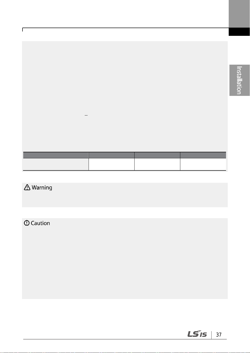
Maximum allowed prospective short-circuit current at the input power connection is defined in
IEC 60439-1 as 100 kA. Depending on the selected MCCB, the LSLV-S100 Series is suitable for
use in circuits capable of delivering a maximum of 100 kA RMS symmetrical amperes at the
drive's maximum rated voltage. The following table shows the recommended MCCB for RMS
symmetrical amperes.
Remarque
Le courant maximum de court-circuit présumé autorisé au connecteur d’alimentation électrique
est défini dans la norme IEC 60439-1 comme égal à 100 kA. Selon le MCCB sélectionné, la
série LSLV-S100 peut être utilisée sur des circuits pouvant fournir un courant RMS symétrique
de 100 kA maximum en ampères à la tension nominale maximale du variateur. Le tableau
suivant indique le MCCB recommandé selon le courant RMS symétrique en ampères.
Working Voltage
UTE100(E/N)
UTS150(N/H/L)
ABS33c
ABS53c
ABS63c
ABS103c
240V(50/60Hz)
50/65 kA
65/100/150 kA
30 kA
35 kA
35 kA
85 kA
480V(50/60Hz)
25/35 kA
35/65/100 kA
7.5 kA
10 kA
10 kA
26 kA
Working
Voltage
UTS150
(N/H/L)
UTS250
(N/H/L)
UTS400
(N/H/L)
ABS103c
ABS203c
ABS403c
480V(50/60Hz)
35/65/100kA
35/65/100kA
35/65/100kA
26kA
26kA
35kA

Safety Information
v
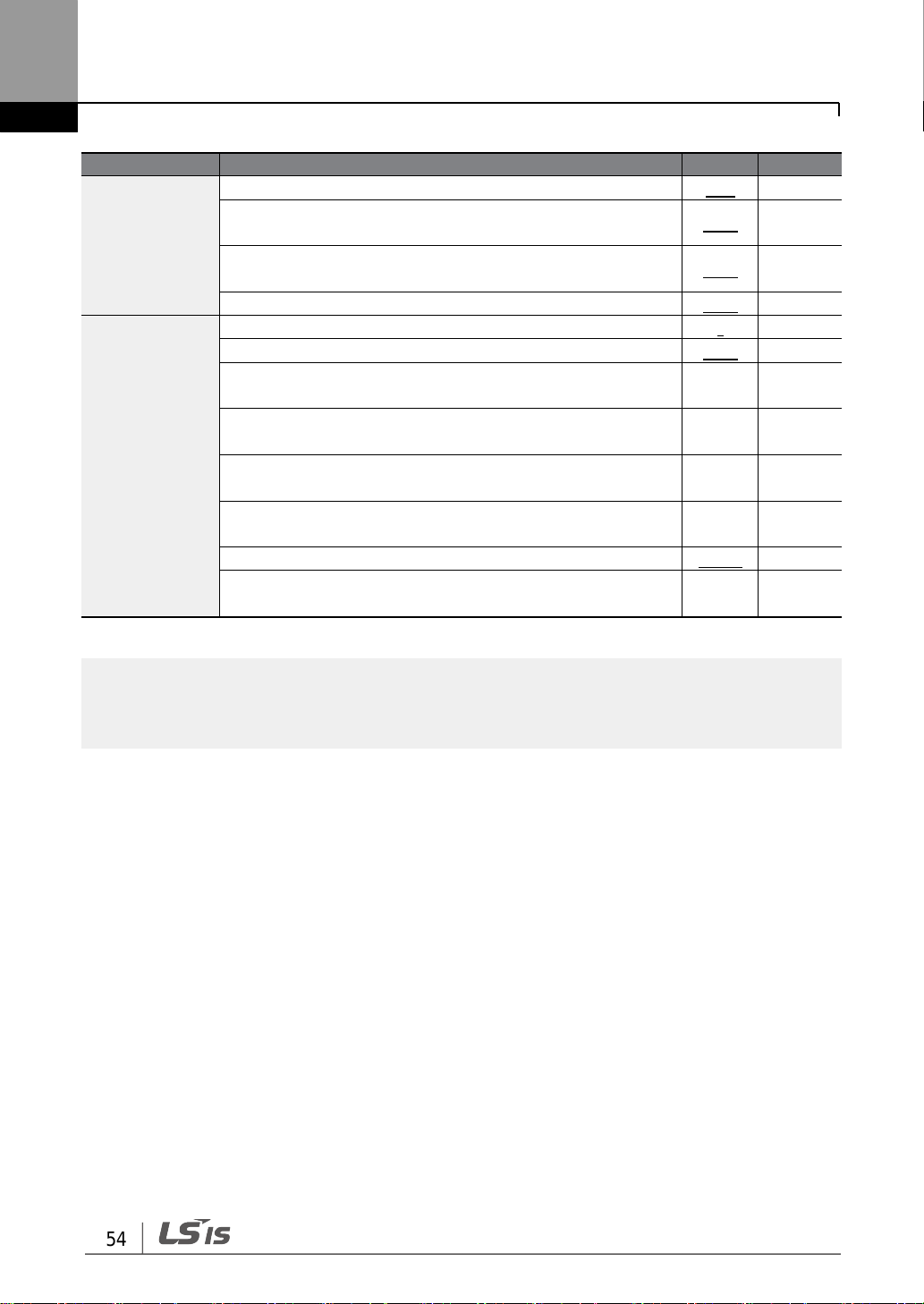
Situation
Reference
I want to run a slightly higher rated motor than the inverter’s rated capacity.
p. 251
I want to configure the inverter to start operating as soon as the power source is
applied.
p. 123
I want to configure the motor’s parameters.
p.183
I want to set up sensorless vector control.
p.187
Something seems to be wrong with the inverter or the motor.
p. 270, p.384
What is auto tuning?
p.183
What are the recommended wiring lengths?
p. 270, p.384
The motor is too noisy.
p. 216
I want to apply PID control on my system.
p. 175
What are the factory default settingss for P1–P7 multi-function terminals?
p. 41
I want to view all of the parameters I have modified.
p. 226
I want to review recent fault trip and warning histories.
p. 350
I want to change the inverter’s operation frequency using a potentiometer.
p. 87
I want to install a frequency meter using an analog terminal.
p. 43
I want to display the supply current to motor.
p. 90
I want to operate the inverter using a multi-step speed configuration.
p. 115
The motor runs too hot.
p. 250
The inverter is too hot.
p. 259
The cooling fan does not work.
p. 390
I want to change the items that are monitored on the keypad.
p. 246
Quick Reference Table
The following table contains situations frequently encountered by users while working with
inverters. Refer to the typical and practical situations in the table to quickly and easily locate
answers to your questions.

vi
Table of Contents
Table of Contents
1 Preparing the Installation .................................................................................. 1
1.1 Product Identification ................................................................................. 1
1.2 Part Names ................................................................................................ 3
0.4-22kW Models .......................................................................... 3
30-75kW Models ........................................................................... 5
IP66 Models .................................................................................. 6
1.3 Installation Considerations ........................................................................ 8
1.4 Selecting and Preparing a Site for Installation ......................................... 9
1.5 Cable Selection ....................................................................................... 13
2 Installing the Inverter ....................................................................................... 15
2.1 Mounting the Inverter .............................................................................. 17
2.2 Cable Wiring ............................................................................................ 21
2.3 Post-Installation Checklist ....................................................................... 53
2.4 Test Run ................................................................................................... 55
3 Learning to Perform Basic Operations ........................................................ 57
3.1 About the Keypad .................................................................................... 57
0.4-22kW Models ........................................................................ 57
30-75kW Models ......................................................................... 58
About the Display ........................................................................ 58
Operation Keys ........................................................................... 62
Control Menu ............................................................................... 64
3.2 Learning to Use the Keypad ................................................................... 67
Display Mode Selection (30-75kW models only) ...................... 67
Group and Code Selection ......................................................... 70
Navigating Directly to Different Codes....................................... 75
Setting Parameter Values .......................................................... 77
Configuring the [ESC] Key (0.4-22kW models only) ................ 80
3.3 Actual Application Examples .................................................................. 81
Acceleration Time Configuration (0.4-22kW models only) ....... 81
Frequency Reference Configuration (0.4-22kW models only) 82
Jog Frequency Configuration (0.4-22kW models only) ............ 83

vii
Table of Contens
Initializing All Parameters ........................................................... 84
Frequency Setting (Keypad) and Operation
(via Terminal Input) .................................................................... 86
Frequency Setting (Potentiometer) and Operation
(Terminal Input) .......................................................................... 87
Frequency Setting (Potentiometer) and Operation (Keypad) .. 88
3.4 Monitoring the Operation ........................................................................ 90
0.4-22kW Models ........................................................................ 90
30-75kW Models ......................................................................... 93
4 Learning Basic Features ................................................................................. 99
4.1 Setting Frequency Reference ............................................................... 102
Keypad as the Source (KeyPad-1 setting) .............................. 102
Keypad as the Source (KeyPad-2 setting) .............................. 103
V1 Terminal as the Source ....................................................... 103
Setting a Frequency Reference with Input Voltage
(Terminal I2) ............................................................................. 110
Setting a Frequency with TI Pulse Input ................................. 111
Setting a Frequency Reference via RS-485
Communication ........................................................................ 113
4.2 Frequency Hold by Analog Input .......................................................... 114
4.3 Changing the Displayed Units (Hz↔Rpm) .......................................... 115
4.4 Setting Multi-step Frequency ................................................................ 115
4.5 Command Source Configuration .......................................................... 117
The Keypad as a Command Input Device .............................. 117
Terminal Block as a Command Input Device
(Fwd/Rev Run Commands) .................................................... 118
Terminal Block as a Command Input Device
(Run and Rotation Direction Commands) .............................. 119
RS-485 Communication as a Command Input Device .......... 120
4.6 Local/Remote Mode Switching ............................................................. 120
4.7 Forward or Reverse Run Prevention ................................................... 122
4.8 Power-on Run ........................................................................................ 123
4.9 Reset and Restart ................................................................................. 124
4.10 Setting Acceleration and Deceleration Times ...................................... 125

viii
Table of Contents
Acc/Dec Time Based on Maximum Frequency ...................... 125
Acc/Dec Time Based on Operation Frequency ...................... 126
Multi-step Acc/Dec Time Configuration ................................... 127
Configuring Acc/Dec Time Switch Frequency......................... 129
4.11 Acc/Dec Pattern Configuration ............................................................. 130
4.12 Stopping the Acc/Dec Operation .......................................................... 132
4.13 V/F(Voltage/Frequency) Control ........................................................... 132
Linear V/F Pattern Operation ................................................... 132
Square Reduction V/F pattern Operation ................................ 133
User V/F Pattern Operation ..................................................... 134
4.14 Torque Boost .......................................................................................... 135
Manual Torque Boost................................................................ 135
Auto Torque Boost-1 ................................................................. 136
Auto Torque Boost-2 ................................................................. 137
4.15 Output Voltage Setting .......................................................................... 137
4.16 Start Mode Setting ................................................................................. 138
Acceleration Start ...................................................................... 138
Start After DC Braking .............................................................. 138
4.17 Stop Mode Setting ................................................................................. 139
Deceleration Stop ..................................................................... 139
Stop After DC Braking .............................................................. 139
Free Run Stop ........................................................................... 141
Power Braking ........................................................................... 141
4.18 Frequency Limit ..................................................................................... 142
Frequency Limit Using Maximum Frequency and Start
Frequency ................................................................................ 142
Frequency Limit Using Upper and Lower Limit Frequency
Values ....................................................................................... 143
Frequency Jump ....................................................................... 144
4.19 2nd Operation Mode Setting .................................................................. 145
4.20 Multi-function Input Terminal Control .................................................... 146
4.21 P2P Setting ............................................................................................ 147
4.22 Multi-keypad Setting .............................................................................. 148

ix
Table of Contens
4.23 User Sequence Setting ......................................................................... 149
4.24 Fire Mode Operation ............................................................................. 157
5 Learning Advanced Features ....................................................................... 159
5.1 Operating with Auxiliary References .................................................... 161
5.2 Jog operation ......................................................................................... 165
Jog Operation 1-Forward Jog by Multi-function Terminal ...... 165
Jog Operation 2-Fwd/Rev Jog by Multi-function Terminal ..... 167
Jog Operation by Keypad......................................................... 167
5.3 Up-down Operation ............................................................................... 168
5.4 3-Wire Operation ................................................................................... 170
5.5 Safe Operation Mode ............................................................................ 171
5.6 Dwell Operation ..................................................................................... 172
5.7 Slip Compensation Operation .............................................................. 174
5.8 PID Control ............................................................................................ 175
PID Basic Operation ................................................................. 176
Pre-PID Operation .................................................................... 181
PID Operation Sleep Mode ...................................................... 182
PID Switching (PID Openloop) ................................................ 183
5.9 Auto Tuning ............................................................................................ 183
5.10 Sensorless Vector Control for Induction Motors .................................. 187
Sensorless Vector Control Operation Setting
for Induction Motors ................................................................. 189
Sensorless Vector Control Operation Guide
for Induction Motors ................................................................. 193
5.11 Sensorless Vector Control for PM (Permanent-Magnet)
Synchronous Motors ............................................................................. 194
Detecting the Initial Pole Position ............................................ 196
Sensorless Vector Control Mode Settings for PM
Synchronous Motors ............................................................... 197
Guidelines for Running a PM Synchronous Motor
in Sensorless Vector Control Mode ........................................ 201
5.12 Kinetic Energy Buffering Operation ...................................................... 204
5.13 Torque Control ....................................................................................... 207
5.14 Energy Saving Operation...................................................................... 210

x
Table of Contents
Manual Energy Saving Operation ........................................... 210
Automatic Energy Saving Operation ....................................... 211
5.15 Speed Search Operation ...................................................................... 211
5.16 Auto Restart Settings ............................................................................ 215
5.17 Operational Noise Settings (carrier frequency settings) ..................... 216
5.18 2nd Motor Operation ............................................................................... 218
5.19 Supply Power Transition ....................................................................... 219
5.20 Cooling Fan Control .............................................................................. 220
5.21 Input Power Frequency and Voltage Settings ..................................... 221
5.22 Read, Write, and Save Parameters ..................................................... 222
5.23 Parameter Initialization .......................................................................... 223
5.24 Parameter View Lock ............................................................................ 224
5.25 Parameter Lock ..................................................................................... 225
5.26 Changed Parameter Display ................................................................ 226
5.27 User Group ............................................................................................ 227
5.28 Easy Start On ........................................................................................ 228
5.29 Config(CNF) Mode ................................................................................ 229
5.30 Timer Settings ........................................................................................ 230
5.31 Brake Control ......................................................................................... 231
5.32 Multi-Function Output On/Off Control .................................................. 232
5.33 Press Regeneration Prevention ........................................................... 233
5.34 Analog Output ........................................................................................ 234
Voltage and Current Analog Output ......................................... 234
Analog Pulse Output ................................................................. 237
5.35 Digital Output ......................................................................................... 240
Multi-function Output Terminal and Relay Settings................. 240
Fault Trip Output using Multi-Function Output
Terminal and Relay .................................................................. 244
Multi-function Output Terminal Delay Time Settings ............... 245
5.36 Keypad Language Settings .................................................................. 246
5.37 Operation State Monitor ........................................................................ 246
5.38 Operation Time Monitor ........................................................................ 249
6 Learning Protection Features ...................................................................... 250

xi
Table of Contens
6.1 Motor Protection .................................................................................... 250
Electronic Thermal Motor Overheating Prevention (ETH) ..... 250
Overload Early Warning and Trip ............................................. 251
Stall Prevention and Flux Braking............................................ 253
6.2 Inverter and Sequence Protection........................................................ 257
Open-phase Protection ............................................................ 257
External Trip Signal ................................................................... 258
Inverter Overload Protection .................................................... 259
Speed Command Loss ............................................................ 259
Dynamic Braking (DB) Resistor Configuration ....................... 261
6.3 Under load Fault Trip and Warning ...................................................... 263
Fan Fault Detection .................................................................. 264
Lifetime diagnosis of components ........................................... 265
Low Voltage Fault Trip .............................................................. 267
Output Block by Multi-Function Terminal ................................. 268
Trip Status Reset ...................................................................... 268
Inverter Diagnosis State ........................................................... 269
Operation Mode on Option Card Trip ...................................... 269
No Motor Trip ............................................................................ 270
Low voltage trip 2 ...................................................................... 270
6.4 Fault/Warning List .................................................................................. 271
7 RS-485 Communication Features ............................................................... 273
7.1 Communication Standards ................................................................... 273
7.2 Communication System Configuration ................................................ 274
Communication Line Connection ............................................ 274
Setting Communication Parameters ....................................... 275
Setting Operation Command and Frequency ......................... 276
Command Loss Protective Operation ..................................... 277
Setting Virtual Multi-Function Input .......................................... 278
Saving Parameters Defined by Communication .................... 278
Total Memory Map for Communication ................................... 279
Parameter Group for Data Transmission ................................ 279
7.3 Communication Protocol....................................................................... 280

xii
Table of Contents
LS INV 485 Protocol ................................................................. 280
Modbus-RTU Protocol .............................................................. 286
7.4 Compatible Common Area Parameter ................................................ 289
7.5 S100 Expansion Common Area Parameter ........................................ 292
Monitoring Area Parameter (Read Only) ................................. 292
Control Area Parameter (Read/ Write) .................................... 297
Inverter Memory Control Area Parameter (Read and Write) . 299
8 Table of Functions.......................................................................................... 302
8.1 Operation Group .................................................................................... 302
8.2 Drive group (PAR→dr) .......................................................................... 303
8.3 Basic Function group (PAR→bA) ......................................................... 309
8.4 Expanded Function group (PAR→Ad) ................................................. 314
8.5 Control Function group (PAR→Cn)...................................................... 319
8.6 Input Terminal Block Function group (PAR→In).................................. 328
8.7 Output Terminal Block Function group (PAR→OU) ............................ 333
8.8 Communication Function group (PAR→CM) ...................................... 338
8.9 Application Function group (PAR→AP) ............................................... 342
8.10 Protection Function group (PAR→Pr) .................................................. 345
8.11 2nd Motor Function group (PAR→M2) ................................................ 350
8.12 User Sequence group (US) .................................................................. 353
8.13 User Sequence Function group(UF) .................................................... 355
8.14 Groups for LCD Keypad Only .............................................................. 376
Trip Mode (TRP Last-x) ............................................................ 376
Config Mode (CNF) .................................................................. 376
9 Troubleshooting ............................................................................................. 380
9.1 Trips and Warnings ............................................................................... 380
Fault Trips .................................................................................. 380
Warning Messages ................................................................... 383
9.2 Troubleshooting Fault Trips .................................................................. 384
9.3 Troubleshooting Other Faults ............................................................... 386
10 Maintenance .................................................................................................... 391
10.1 Regular Inspection Lists ........................................................................ 391
Daily Inspections ....................................................................... 391

xiii
Table of Contens
Annual Inspections ................................................................... 392
Bi-annual Inspections ............................................................... 394
10.2 Replacing Major Components .............................................................. 395
Exchange Cycle for Major Components ................................. 395
10.3 Storage and Disposal ............................................................................ 395
Storage ...................................................................................... 395
Disposal ..................................................................................... 396
11 Technical Specification ................................................................................. 397
11.1 Input and Output Specification ............................................................. 397
0.4-22kW Models ...................................................................... 397
30-75kW Models ....................................................................... 402
11.2 Product Specification Details ................................................................ 404
11.3 External Dimensions ............................................................................. 407
0.4-22kW Models ...................................................................... 407
30-75kW Models ....................................................................... 413
IP66 Models .............................................................................. 415
11.4 Peripheral Devices ................................................................................ 419
0.4-22kW Models ...................................................................... 419
30-75kW Models ....................................................................... 420
11.5 Fuse and Reactor Specifications ......................................................... 421
0.4-22kW Models ...................................................................... 421
30-75kW Models ....................................................................... 422
11.6 Terminal Screw Specification ................................................................ 422
Input/Output Terminal Screw Specification ............................. 422
Control Circuit Terminal Screw Specification .......................... 424
11.7 Dynamic Braking Unit(DBU) and Resistors ......................................... 425
Braking Resistor Specification (0.4-22kW) ............................. 425
Dynamic Braking Unit (30-75kW) ............................................ 426
Terminal arrangement .............................................................. 426
Dynamic Braking Unit Dimensions .......................................... 428
Display Functions ..................................................................... 430
11.8 Continuous Rated Current Derating..................................................... 431
Dynamic Braking Unit Resistors .............................................. 430

xiv
Table of Contents
11.9 Heat Emmission .................................................................................... 434
12 Applying Drives to Single-Phase Input Application ................................. 435
12.1 Introduction ............................................................................................ 435
12.2 Power(HP), Input Current and Output Current .................................... 436
12.3 Input Frequency and Voltage Tolerance .............................................. 437
Product Warranty .................................................................................................. 438
Index ........................................................................................................................ 446

Preparing the Installation
1
Note
Check the product name, open the packaging, and then confirm that the product is free from
defects. Contact your supplier if you have any issues or questions about your product.
1 Preparing the Installation
This chapter provides details on product identification, part names, correct installation and
cable specifications. To install the inverter correctly and safely , carefully read and follow the
instructions.
1.1 Product Identification
The S100 Inverter is manufactured in a range of product groups based on drive capacity
and power source specifications. Product name and specifications are detailed on the rating
plate. The illustration on the next page shows the location of the rating plate. Check the
rating plate before installing the product and make sure that the product meets your
requirements. For more detailed product specifications, refer to 11.1 Input and Output
Specification on page 397.

Preparing the Installation
2

Preparing the Installation
3
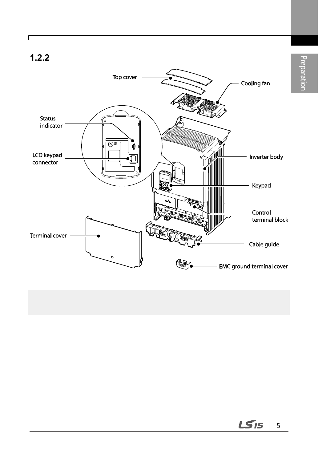
1.2 Part Names
The illustration below displays part names. Details may vary between product groups.
0.4-22kW Models
0.4-2.2kW (Single Phase) and 0.4-4.0kW (3–Phase)

Preparing the Installation
4
5.5–22kW(3–Phase)
Preparing the Installation
5
Note
The grounding terminal cover of EMC is not existed in the 55-75kW inverters.
30-75kW Models

Preparing the Installation
6
IP66 Models
Do not operate Disconnect Switch when motor is operating.
The installation location for cooling fan varies according to product capacity.
Inside the product: 0.4-4.0kW; bottom of the product: 5.5-7.5kW; inside and top of the
product: 11-22kW.

Preparing the Installation
7
Front cover removed
Preparing the Installation
8
Items
Description
Ambient Temperature*
Heavy Duty: 14–104F (-10–50℃) Normal Duty: 14–122F (-10– 40℃)
Ambient Humidity
90% relative humidity (no condensation)
Storage Temperature
- 4–149F (-20–65℃)
Environmental Factors
An environment free from corrosive or flammable gases,
oil residue or dust
Altitude
/ Vibration
Maximum 1000m above sea level for standard operation. From 1000
to 4000m, the rated input voltage and rated output current of the drive
must be derated by 1% for every 100m. / less than 1G (9.8m/sec2)
Air Pressure
70 –106kPa
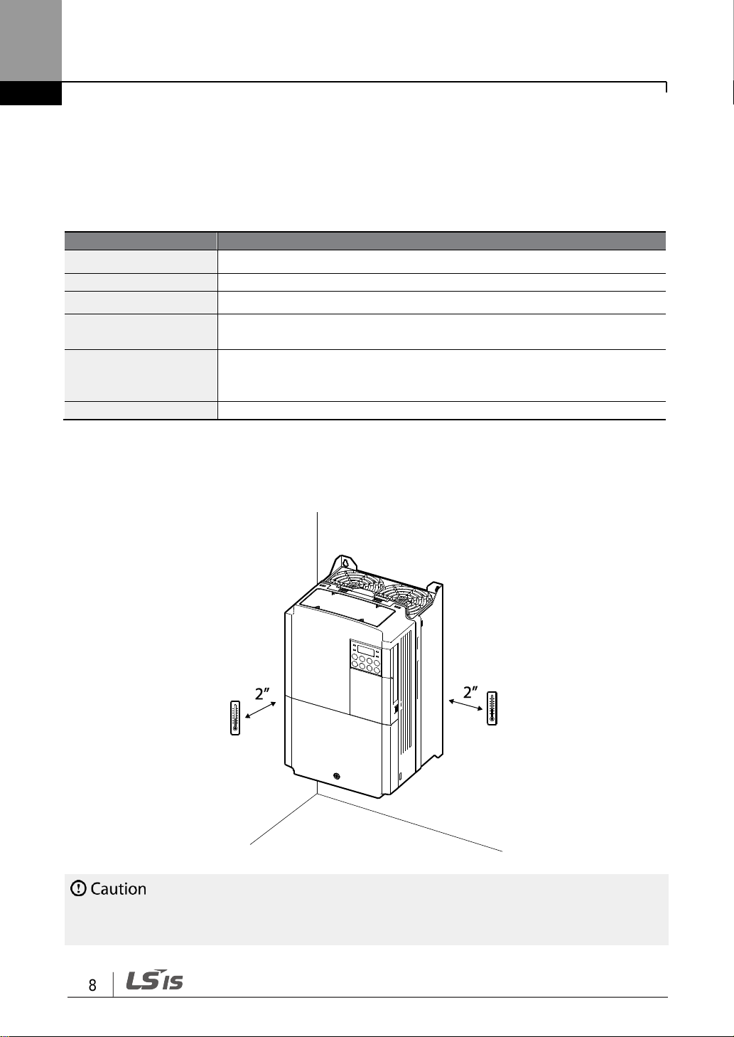
Do not allow the ambient temperature to exceed the allowable range while operating the
inverter.
1.3 Installation Considerations
Inverters are composed of various precision, electronic devices, and therefore the
installation environment can significantly impact the lifespan and reliability of the product.
The table below details the ideal operation and installation conditions for the inverter.
* The ambient temperature is the temperature measured at a point 2” (5 cm) from the
surface of the inverter.
* IP66 models only support heavy load operation, and an ambient temperature of between
-10℃ – +40℃.
Preparing the Installation
9
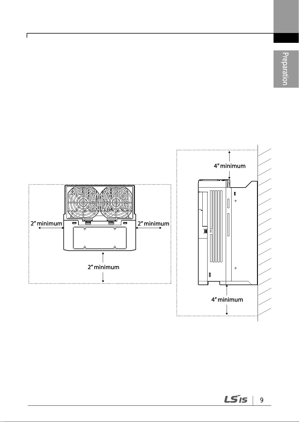
1.4 Selecting and Preparing a Site for Installation
When selecting an installation location consider the following points:
• The location must be free from vibration, and the inverter must be installed on a wall
that can support the inverter’s weight.
• The inverter can become very hot during operation. Install the inverter on a surface that
is fire-resistant or flame-retardant and with sufficient clearance around the inverter to
allow air to circulate. The illustrations below detail the required installation clearances.
Preparing the Installation
10
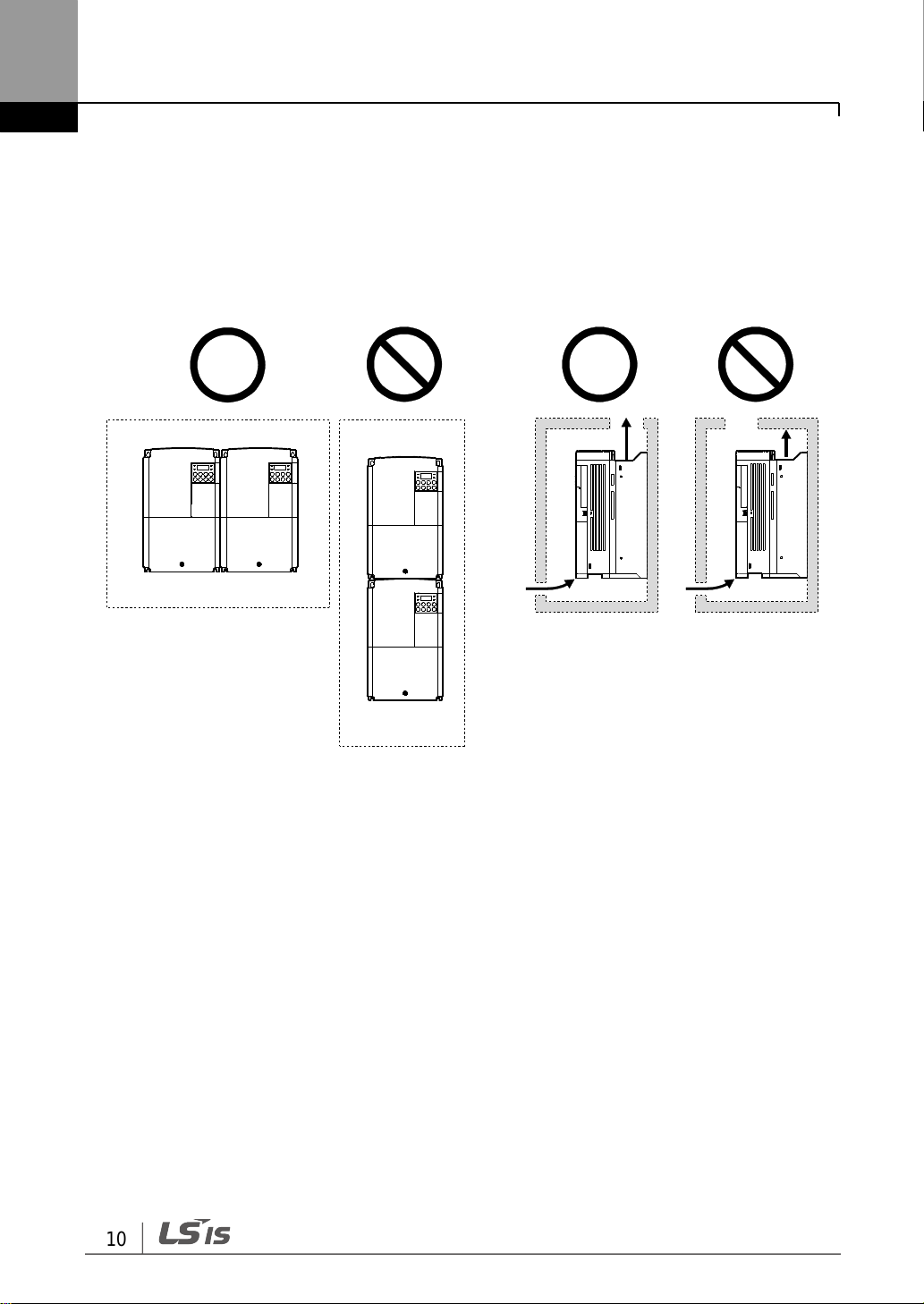
• Ensure sufficient air circulation is provided around the inverter when it is installed . If the
inverter is to be installed inside a panel, enclosure, or cabinet rack, carefully consider
the position of the inverter’s cooling fan and the ventilation louver. The cooling fan must
be positioned to efficiently transfer the heat generated by the operation of the inverter.
Preparing the Installation
11
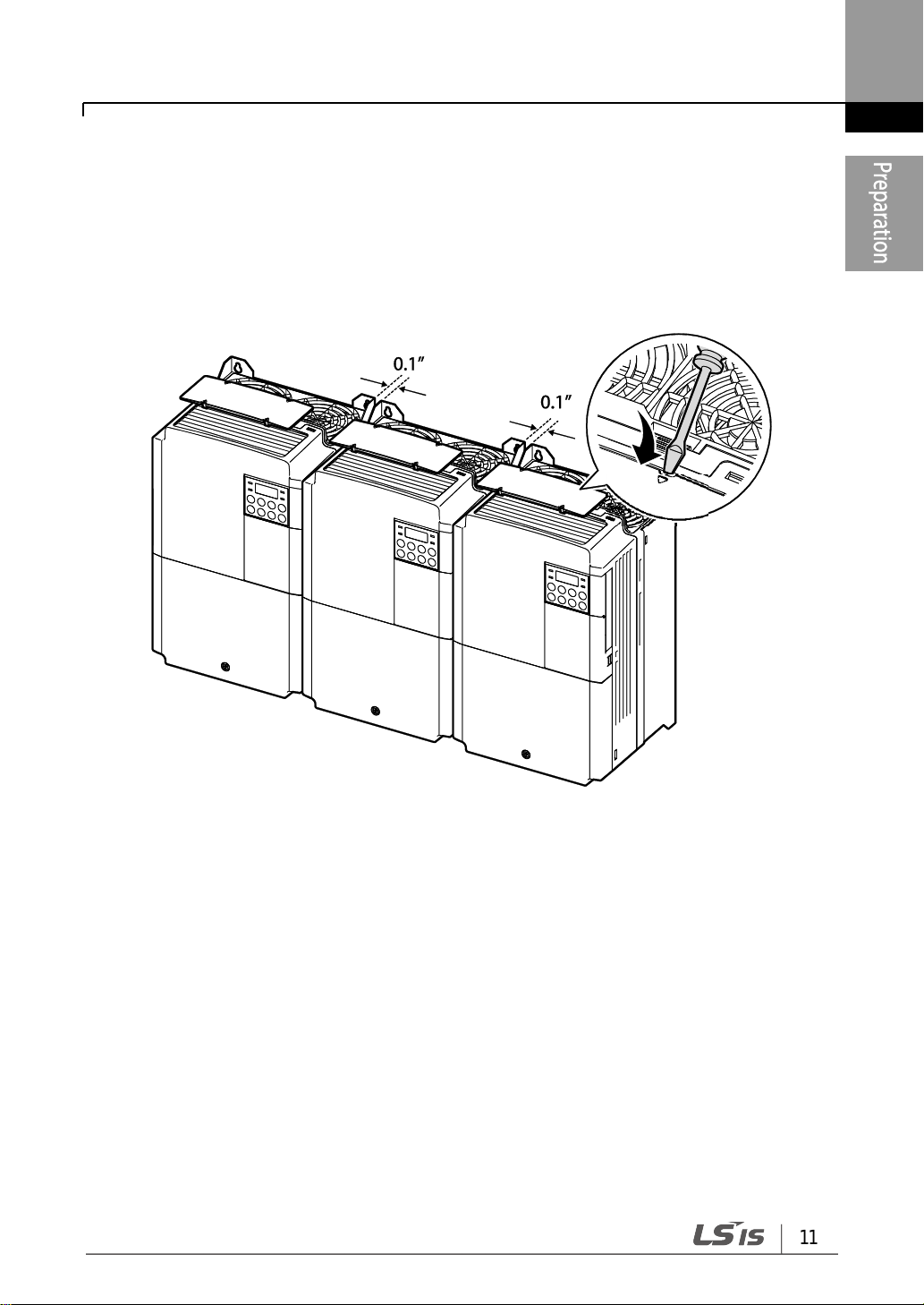
• If you are installing multiple inverters in one location, arrange them side-by -side and
remove the top covers. The top covers MUST be removed for side-by-side installations.
Use a flat head screwdriver to remove the top covers.
• Side-by-side operation only supports 0.4-22kW, IP20 models.

Preparing the Installation
12
• If you are installing multiple inverters, of different ratings, provide sufficient clearance to
meet the clearance specifications of the larger inverter.

Preparing the Installation
13
• Wherever possible use cables with the largest cross-sectional area for mains power
wiring, to ensure that voltage drop does not exceed 2%.
• Use copper cables rated for 600V, 75℃ for power terminal wiring.
• Use copper cables rated for 300V, 75℃ for control terminal wiring.
Load (kW)
Ground
Power I/O
mm2
AWG
mm2
AWG
R/S/T
U/V/W
R/S/T
U/V/W
Single Phase
200V
0.4
4
12
2 2 14
14
0.75
1.5
2.2
3.5
3.5
12
12
3–Phase
200V
0.4
2 2 14
14
0.75
1.5
2.2
3.7
3.5
3.5
12
12
4
5.5
5.5
10 6 6
10
10
7.5
11
14
6
10
10 8 8
15
16
16 6 6
3–Phase
400V
0.4
4
12 2 2
14
14
0.75
1.5
2.2
3.7
4
5.5
4
12
2.5
2.5
14
14
7.5
4 4 12
12
11
8
8
15 6 6
10
10
18.5
14 6 10
10 8 8
22
1.5 Cable Selection
When you install power and signal cables in the terminal blocks, only use cables that meet
the required specification for the safe and reliable operation of the product. Refer to the
following information to assist you with cable selection.
Ground Cable and Power Cable Specifications (0.4-22kW)

Preparing the Installation
14
Load (kW)
Ground
Power I/O
mm2
AWG
mm2
AWG
R/S/T
U/V/W
R/S/T
U/V/W
3–Phase
400V
30
16
5
25
25 4 4
37
45
70
70
1/0
1/0
55
35
3
75
2
Terminals
Signal Cable
Without Crimp Terminal
Connectors
(Bare wire)
With Crimp Terminal Connectors
(Bootlace Ferrule)
mm2
AWG
mm2
AWG
P1~P7*/CM/VR/V1/I2
/AO1,AO2/Q1/EG/24/TI/
TO* /SA,SB,SC/S+,
S-,SG
0.75
18
0.5
20
A1/B1/C1/A2/C2
1.0
17
1.5
15
Ground Cable and Power Cable Specifications (30-75kW)
Signal (Control) Cable Specifications
* Standard I/O doesn’t support P6/P7/TI/TO terminal. Refer to Step 4 Control Terminal
Wiring on page 38.

15
Installing the Inverter
Product Identification (p.1)
Select the Installation Location (p.8)
Mounting the Inverter (p.17)
Wiring the Ground Connection (p. 28)
Power and Signal Wiring (p.32)
Post-Installation Checks (p.53)
Turning on the Inverter
Parameter Configuration (p.81)
Testing (p.55)
2 Installing the Inverter
This chapter describes the physical and electrical installation methods, including mounting
and wiring of the product. Refer to the flowchart and basic configuration diagram provided
below to understand the procedures and installation methods to be followed to install the
product correctly.
Installation Flowchart
The flowchart lists the sequence to be followed during installation. The steps cover
equipment installation and testing of the product. More information on each step is
referenced in the steps.
*

Installing the Inverter
16
• Figures in this manual are shown with covers or circuit breakers removed to show a more
detailed view of the installation arrangements. Install covers and circuit breakers before
operating the inverter. Operate the product according to the instructions in this manual.
• Do not start or stop the inverter using a magnetic contactor, installed on the input power
supply.
• If the inverter is damaged and loses control, the machine may cause a dangerous situation.
Install an additional safety device such as an emergency brake to prevent these situations.
• High levels of current draw during power-on can affect the system. Ensure that
correctly rated circuit breakers are installed to operate safely during power-on
situations.
• Reactors can be installed to improve the power factor. Note that reactors may be
installed within 30 ft (9.14 m) from the power source if the input power exceeds 10
times 0f inverter capacity. Refer to 11.5 Fuse and Reactor Specifications on page 421
and carefully select a reactor that meets the requirements.
• 30-75kW models have a built-in DC Reactor.
Basic Configuration Diagram
The reference diagram below shows a typical system configuration showing the inverter
and peripheral devices.
Prior to installing the inverter, ensure that the product is suitable for the application (power
rating, capacity, etc). Ensure that all of the required peripherals and optional devices
(resistor brakes, contactors, noise filters, etc.) are available. For more details on peripheral
devices, refer to 11.4 Peripheral Devices on page 419.

17
Installing the Inverter
2.1 Mounting the Inverter
Mount the inverter on a wall or inside a panel following the procedures provided below.
Before installation, ensure that there is sufficient space to meet the clearance specifications,
and that there are no obstacles impeding the cooling fan’s air flow.
Select a wall or panel suitable to support the installation. Refer to 11.3 External Dimensions
on page 407 and check the inverter’s mounting bracket dimensions.
1 Use a level to draw a horizontal line on the mounting surface, and then carefully mark
the fixing points.
2 Drill the two upper mounting bolt holes, and then install the mounting bolts. Do not fully
tighten the bolts at this time. Fully tighten the mounting bolts after the inverter has been
mounted.

Installing the Inverter
18
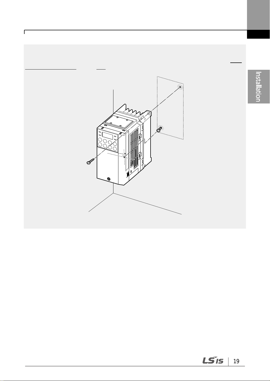
3 Mount the inverter on the wall or inside a panel using the two upper bolts, and then fully
tighten the mounting bolts. Ensure that the inverter is placed flat on the mounting
surface, and that the installation surface can securely support the weight of the inverter.
19
Installing the Inverter
Note
The quantity and dimensions of the mounting brackets vary based on frame size. Refer to 11.3
External Dimensions on page 407 for detailed information about your model.
0.4kW (Single Phase) and 0.4-0.8kW (3-phase) inverters have only two mounting brackets.
Installing the Inverter
20
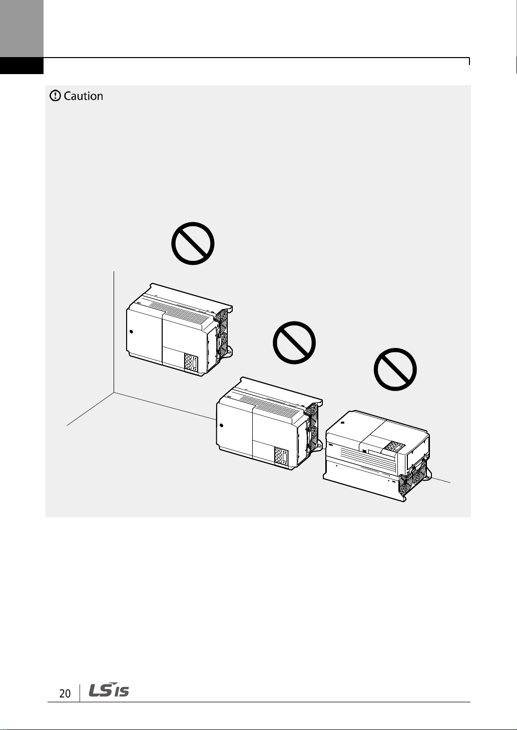
• Do not transport the inverter by lifting with the inverter’s covers or plastic surfaces. The
inverter may tip over if covers break, causing injuries or damage to the product. Always
support the inverter using the metal frames when moving it.
• High-capacity inverters are very heavy and bulky. Use an appropriate transport method that
is suitable for the weight.
• Do not install the inverter on the floor or mount it sideways against a wall. The inverter
MUST be installed vertically, on a wall or inside a panel, with its rear flat on the mounting
surface.

21
Installing the Inverter
• Install the inverter before carrying out wiring connections.
• Ensure that no small metal debris, such as wire cut-offs, remain inside the inverter. Metal
debris in the inverter may cause inverter failure.
• Tighten terminal screws to their specified torque. Loose terminal block screws may allow
the cables to disconnect and cause short circuit or inverter failure. Refer to 11.6 Terminal
Screw Specification on page 422 for torque specifications.
• Do not place heavy objects on top of electric cables. Heavy objects may damage the cable
and result in electric shock.
• The power supply system for this equipment (inverter) is a grounded system. Only use a
grounded power supply system for this equipment (inverter). Do not use a TT, TN, IT, or
corner grounded system with the inverter.
• The equipment may generate direct current in the protective ground wire. When installing
the residual current device (RCD) or residual current monitoring (RCM), only Type B RCDs
and RCMs can be used.
• Use cables with the largest cross-sectional area, appropriate for power terminal wiring, to
ensure that voltage drop does not exceed 2%.
• Use copper cables rated at 600V, 75℃ for power terminal wiring.
• Use copper cables rated at 300V, 75℃ for control terminal wiring.
• Separate control circuit wires from the main sircuits and other high voltage circuits(200V
relay sequence circuit).
• Check for short circuits or wiring failure in the control circuit. They could cause system
failure or device malfunction.
• Use shielded cables when wiring the control circuit. Failure to do so may cause malfunction
due to interference. If a ground is needed, use STP (Shielded Twisted Pair) cables.
• If you need to re-wire the terminals due to wiring-related faults, ensure that the inverter
keypad display is turned off and the charge lamp under the front cover is off before working
on wiring connections. The inverter may hold a high voltage electric charge long after the
power supply has been turned off.
2.2 Cable Wiring
Open the front cover, remove the cable guides and control terminal cover, and then install
the ground connection as specified. Complete the cable connections by connecting an
appropriately rated cable to the terminals on the power and control terminal blocks.
Read the following information carefully before carrying out wiring connections to the
inverter. All warning instructions must be followed.
Installing the Inverter
22
Step 1 Front Cover, Control Terminal Cover and Cable Guide
The front cover, control terminal cover and cable guide must be removed to install cables.
Refer to the following procedures to remove the covers and cable guide. The steps to
remove these parts may vary depending on the inverter model.
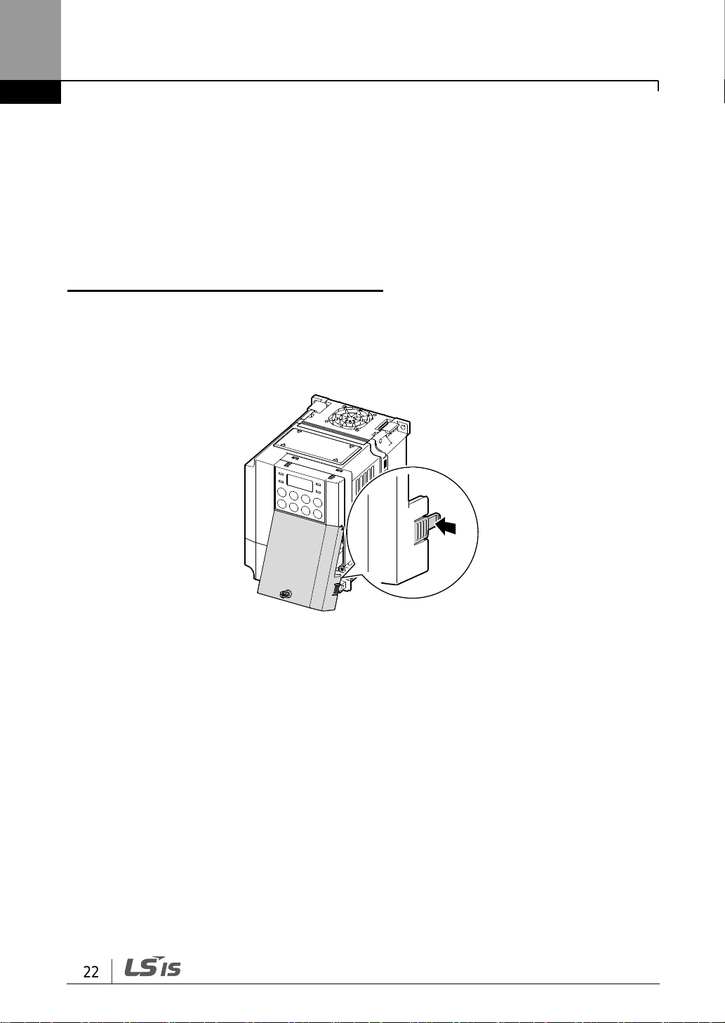
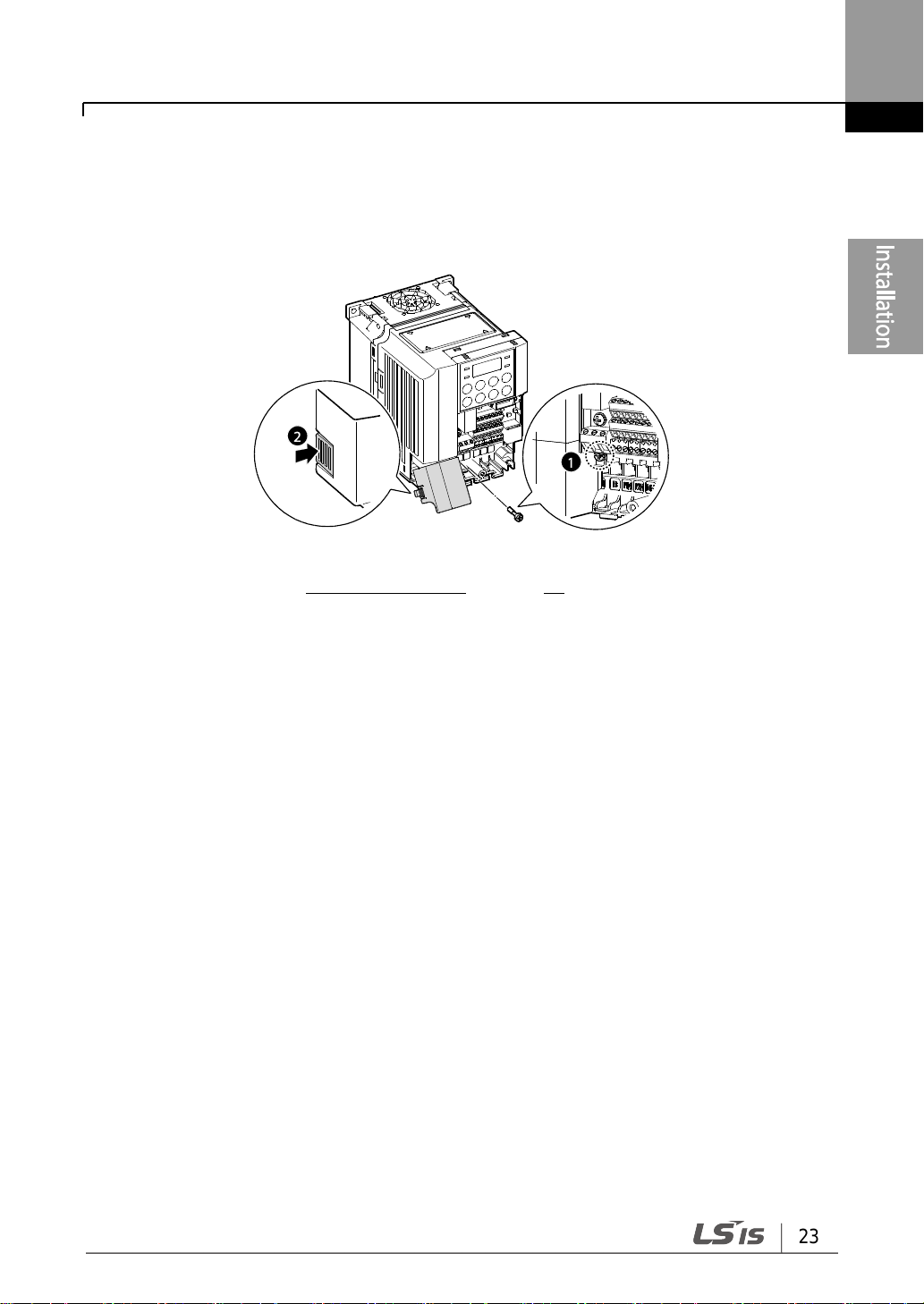
0.8–1.5kW (single phase), 1.5–2.2kW (3-phase)
1 Loosen the bolt that secures the front cover (right side). Push and hold the latch on the
right side of the cover. Then remove the cover by lifting it from the bottom and moving it
away from the front of the inverter.
23
Installing the Inverter
2 Remove the bolt that secures the front cover (left side) (❶). Push and hold the latch on
the left side of the cover. Then remove the cover by lifting it from the bottom and
moving it away from the front of the inverter (❷).
3 Connect the cables to the power terminals and the control terminals. For cable
specifications, refer to 1.5 Cable Selection on page 13.
Installing the Inverter
24
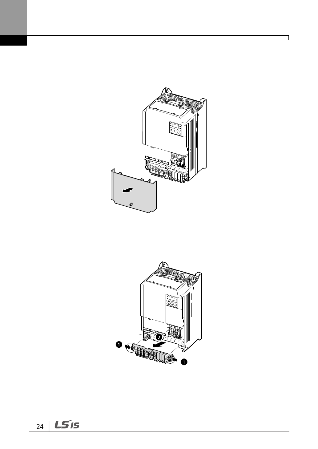
5.5–22kW (3-phase)
1 Loosen the bolt that secures the front cover. Then remove the cover by lifting it from the
bottom and away from the front.
2 Push and hold the levers on both sides of the cable guide (❶) and then remove the
cable guide by pulling it directly away from the front of the inverter (❷). In some models
where the cable guide is secured by a bolt, remove the bolt first.

25
Installing the Inverter
Note
To connect an LCD loader, remove the plastic knock-out from the bottom of the front cover (right
side). Connect the signal cable of the LCD loader to the RJ-45 port on the control board. (0.422kW models only)
3 Push and hold the tab on the right side of the control terminal cover. Then remove the
cover by lifting it from the bottom and moving it away from the front of the inverter.
4 Connect the cables to the power terminals and the control terminals. For cable
specifications, refer to 1.5 Cable Selection on page 13.
Installing the Inverter
26
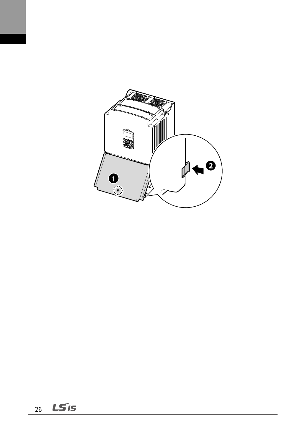
30-75kW(3-phase 4type)
1 Loosen the bolt that secures the terminal cover (). Push and hold the latch on the
right side of the cover (). Then remove the cover by lifting it from the bottom and
moving it away from the front of the inverter.
2 Connect the cables to the power terminals and the control terminals. For cable
specifications, refer to 1.5 Cable Selection on page 13.

27
Installing the Inverter
IP66
0.4-15kW (3-phase 2type), 0.4-22kW (3-phase 4type)
1 Loosen the bolt that secures the front cover. Then remove the cover by lifting it from the
bottom and moving it away from the front of the inverter.
2 Set the bushing to every wiring hole before installing to power and I/O board terminals.
Use the bushing that is NEMA 4X (IP66) or more.

Installing the Inverter
28
Note
To connect an LCD loader, remove the plastic knock-out from the bottom of the front cover (right
side). Connect the signal cable of the LCD loader to the RJ-45 port on the control board. (0.422kW models only)
Note
• 200 V products require Class 3 grounding. Resistance to ground must be < 100Ω.
• 400 V products require Special Class 3 grounding. Resistance to ground must be < 10Ω.
Install ground connections for the inverter and the motor by following the correct specifications to
ensure safe and accurate operation. Using the inverter and the motor without the specified
grounding connections may result in electric shock.
3 Connect the cables to the power terminals and the control terminals. For cable
specifications, refer to 1.5 Cable Selection on page 13.
Step 2 Ground Connection
Remove the front cover(s), cable guide, and the control terminal cover. Then follow the
instructions below to install the ground connection for the inverter.

29
Installing the Inverter
0.4-22kW
1 Locate the ground terminal and connect an appropriately rated ground cable to the
terminals. Refer to 1.5 Cable Selection on page 13 to find the appropriate cable
specification for your installation.
2 Connect the other ends of the ground cables to the supply earth (ground) terminal.

Installing the Inverter
30
30-75kW
1 Locate the ground terminal and connect an appropriately rated ground cable to the
terminals. Refer to 1.5 Cable Selection on page 13 to find the appropriate cable
specification for your installation.
2 Connect the other ends of the ground cables to the supply earth (ground) terminal.

31
Installing the Inverter
IP66
1 Locate the ground terminal and connect an appropriately rated ground cable to the
terminals. Refer to 1.5 Cable Selection on page 13 to find the appropriate cable
specification for your installation.
2 Connect the other ends of the ground cables to the supply earth (ground) terminal.

Installing the Inverter
32
• Apply rated torques to the terminal screws. Loose screws may cause short circuits and
malfunctions. Tightening the screw too much may damage the terminals and cause short
circuits and malfuctions.
• Use copper wires only with 600V, 75℃ rating for the power terminal wiring, and 300V,
75℃rating for the control terminal wiring.
• Do not connect two wires to one terminal when wiring the power.
• Power supply wirings must be connected to the R, S, and T terminals. Connecting them to
the U, V, W terminals causes internal damages to the inverter. Motor should be connected
to the U, V, and W Terminals. Arrangement of the phase sequence is not necessary.
• Tighten terminal screws to their specified torque. Loose terminal screws may allow the
cables to disconnect and cause short circuit or inverter failure. Over tightening
terminal screws may damage the terminals and cause short circuits and malfunctions.
• Use copper cables rated for 600V, 75℃ for power terminal wiring.
• Use copper cables rated for 300V, 75℃ for control terminal wiring.
• Power supply cables must be connected to the R, S, and T terminals. Connecting
power cables to the U, V, and W terminals will cause internal damage to the inverter.
Connect motors to the U, V, and W terminals. Phase sequence arrangement is not
necessary.
• Appliquer des couples de marche aux vis des bornes. Des vis desserrées peuvent
provoquer des courts-circuits et des dysfonctionnements. Ne pas trop serrer la vis, car cela
risqué d’endommager les bornes et de provoquer des courts-circuits et des
dysfonctionnements. Utiliser uniquement des fils de cuivre avec une valeur nominale de
600 V, 75 ℃ pour le câblage de la borne d’alimentation, et une valeur nominale de 300 V,
75 ℃ pour le câblage de la borne de commande.
• Ne jamais connecter deux câbles à une borne lors du câblage de l'alimentation.
• Les câblages de l’alimentation électrique doivent être connectés aux bornes R, S et T.
Leur connexion aux bornes U, V et W provoque des dommages internes à l’onduleur.
Le moteur doit être raccordé aux bornes U, V et W. L’arrangement de l’ordre de phase
n’est pas nécessaire.
Step 3 Power Terminal Wiring
The following illustration shows the terminal layout on the power terminal block. Refer to the
detailed descriptions to understand the function and location of each terminal before making
wiring connections. Ensure that the cables selected meet or exceed the specifications in 1.5
Cable Selection on page 13 before installing them.

33
Installing the Inverter
0.4-22kW
0.4kW (single phase), 0.4-0.8kW (3-phase)
0.8–1.5kW (single phase), 1.5–2.2kW (3-phase)
2.2kW (single phase), 3.7-4.0kW (3-phase)

Installing the Inverter
34
Terminal Labels
Name
Description
R(L1)/S(L2)/T(L3)
AC power input terminal
Mains supply AC power connections.
P1(+)/N(-)
DC link terminal
DC voltage terminals.
P1(+)/P2(+)
DC reactor terminal
DC reactor wiring connection. (When
you use the DC reactor, must remove
short-bar)
P2(+)/B
Brake resistor terminals
Brake resistor wiring connection.
U/V/W
Motor output terminals
3-phase induction motor wiring
connections.
5.5–22kW (3-phase)
Power Terminal Labels and Descriptions (0.4-22kW)
30-75kW (3-phase)
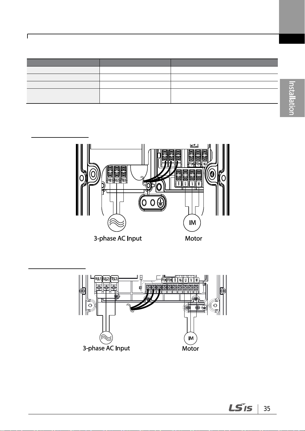
35
Installing the Inverter
Terminal Labels
Name
Description
R(L1)/S(L2)/T(L3)
AC power input terminal
Mains supply AC power connections.
P2(+)/N(-)
DC link terminal
DC voltage terminals.
P3(+)/N(-)
Brake unit terminals
Brake unit wiring connection.
U/V/W
Motor output terminals
3-phase induction motor wiring
connections.
Power Terminal Labels and Descriptions (30-75kW)
IP66
0.4-0.8kW (3-phase)
1.5-2.2kW (3-phase)

Installing the Inverter
36
Terminal Labels
Name
Description
R(L1)/S(L2)/T(L3)
AC power input terminal
Mains supply AC power connections.
P1(+)/N(-)
DC link terminal
DC voltage terminals.
P1(+)/P2(+)
DC reactor terminal
DC reactor wiring connection. (Remove
the short-bar when you use the DC
reactor.)
P2(+)/B
Brake resistor terminals
Brake resistor wiring connection.
U/V/W
Motor output terminals
3-phase induction motor wiring
connections.
3.7-4.0kW (3-phase)
5.5–22kW (3-phase)
Power Terminal Labels and Descriptions (IP66)
37
Installing the Inverter
Note
• Do not use 3 core cables to connect a remotely located motor with the inverter.
• When you operating Brake resistor, the motor may vibrate under the Flux braking operation.
In this case, please turn off the Flux braking(Pr.50).
• Make sure that the total cable length does not exceed 665ft (202m). For inverters < =
4.0kW capacity, ensure that the total cable length does not exceed 165ft (50m).
• Long cable runs can cause reduced motor torque in low frequency applications due to
voltage drop. Long cable runs also increase a circuit’s susceptibility to stray capacitance
and may trigger over-current protection devices or result in malfunction of equipment
connected to the inverter.
• Voltage drop is calculated by using the following formula:
Voltage Drop (V) = [ X cable resistance (mΩ/m) X cable length (m) X current(A)] /
1000
• Use cables with the largest possible cross-sectional area to ensure that voltage drop is
minimized over long cable runs. Lowering the carrier frequency and installing a micro surge
filter may also help to reduce voltage drop.
Distance
< 165ft (50m)
< 330ft (100m)
> 330ft (100m)
Allowed Carrier Frequency
< 15 kHz
(30-75kW: < 5 kHz)
< 5 kHz
< 2.5 kHz
Do not connect power to the inverter until installation has been fully completed and the inverter is
ready to be operated. Doing so may result in electric shock.
• Power supply cables must be connected to the R, S, and T terminals. Connecting power
cables to other terminals will damage the inverter.
• Use insulated ring lugs when connecting cables to R/S/T and U/V/W terminals.
• The inverter’s power terminal connections can cause harmonics that may interfere with
other communication devices located near to the inverter. To reduce interference the
installation of noise filters or line filters may be required.
• To avoid circuit interruption or damaging connected equipment, do not install phase-
advanced condensers, surge protection, or electronic noise filters on the output side of the
inverter.
• To avoid circuit interruption or damaging connected equipment, do not install magnetic
contactors on the output side of the inverter.

Installing the Inverter
38
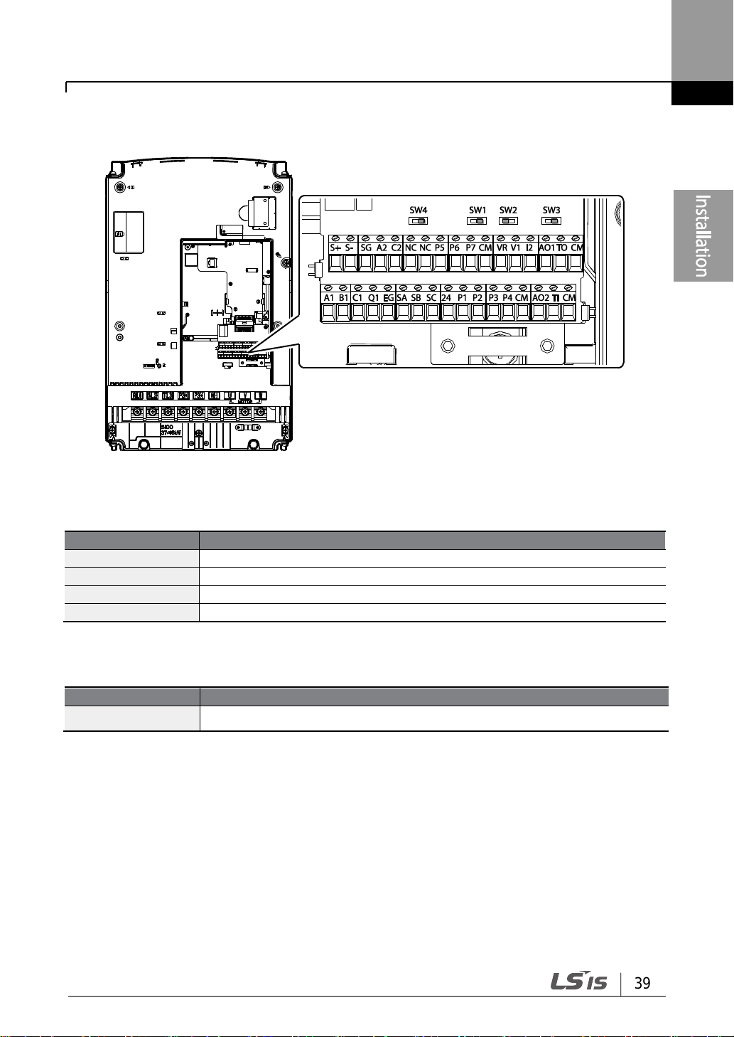
Step 4 Control Terminal Wiring
The illustrations below show the detailed layout of control wiring terminals, and control
board switches. Refer to the detailed information provided below and 1.5 Cable Selection
on page 13 before installing control terminal wiring and ensure that the cables used meet
the required specifications.
0.4-22kW
<Standard I/O>
<Multiple I/O>
39
Installing the Inverter
Switch
Description
SW1
NPN/PNP mode selection switch
SW2
analog voltage/current input terminal selection switch
SW3
analog voltage/current output terminal selection switch
SW4
Terminating Resistor selection switch
Name
Description
Connector
Connect to iS7 Loader or Smart Copier
30-75kW
<30-75kW I/O>
Control Board Switches
Connector (0.4-22kW models only)
Installing the Inverter
40
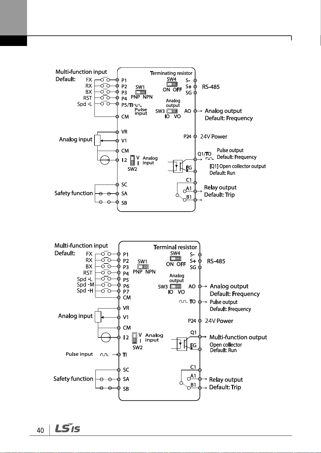
0.4-22kW
<Standard I/O>
<Multiple I/O>

41
Installing the Inverter
Function
Label
Name
Description
Multi-
function
terminal
configuration
P1–P7
Multi-function
Input 1-7
Configurable for multi-function input terminals.
(Standard I/O is only provided for P5.)
CM
Common
Sequence
Common terminal for analog terminal inputs and
outputs.
Analog input
configuration
VR
Potentiometer
frequency
reference input
Used to setup or modify a frequency reference via
analog voltage or current input.
• Maximum Voltage Output: 12V
• Maximum Current Output: 100mA,
• Potentiometer: 1–5kΩ
V1
Voltage input for
frequency
reference input
Used to setup or modify a frequency reference via
analog voltage input terminal.
• Unipolar: 0–10V (12V Max.)
• Bipolar: -10–10V (±12V Max.)
I2
Voltage/current
input for
Used to setup or modify a frequency reference via
analog voltage or current input terminals.
30-75kW
Input Terminal Labels and Descriptions

Installing the Inverter
42
Function
Label
Name
Description
frequency
reference input
Switch between voltage (V2) and current (I2)
modes using a control board switch (SW2).
V2 Mode:
• Unipolar: 0–10V (12V Max.)
I2 Mode
• Input current: 4–20mA
• Maximum Input current: 24mA
• Input resistance: 249Ω
TI
Pulse input for
frequency
reference input
(pulse train)
Setup or modify frequency references using pulse
inputs from 0 to 32kHz.
• Low Level: 0–2.5V
• High Level: 3.5–12V
(In case of Standard I/O, Pulse input TI and Multifunction terminal P5 share the same terminal. Set
the ln.69 P5 Define to 54(TI).).
Safety
functionality
configuration
SA
Safety input A
Used to block the output from the inverter in an
emergency.
Conditions:
• Normal Operation: Both the SA and SB
terminals are connected to the SC terminal.
• Output Block: One or both of the SA and SB
terminals lose connection with the SC
terminal.
SB
Safety input B
SC
Safety input
power source
DC 24V, < 25mA

43
Installing the Inverter
Function
Label
Name
Description
Analog output
AO, AO1
Voltage/Current
Output
Used to send inverter output information to
external devices: output frequency, output
current, output voltage, or a DC voltage.
Operate switch (SW3) to select the signal output
type (voltage or current) at the AO terminal.
Output Signal Specifications:
• Output voltage: 0–10V
• Maximum output voltage/current: 12V/10mA
• Output current: 0–20mA
• Maximum output current: 24mA
• Factory default output: Frequency
AO2
Analog voltage
output terminal
Use to send inverter output information, such as
output frequency, output current, output voltage,
or DC voltage to external devices.
• Output voltage: 0–10 V
• Maximum output voltage/current: 12V/10 mA
TO
Pulse Output
Sends pulse signals to external devices to
provide a single output value from the inverter of
either: output frequency, output current, output
voltage, or DC voltage.
Output Signal Specifications:
• Output frequency: 0–32kHz
• Output voltage: 0–12V
• Factory default output: Frequency
(In case of Standard I/O, Pulse output TO and
Multi-function output Q1 share the same
terminal. Set the OU.33Q1 Define to 38(TO).)
When connecting to a pulse between the S100
inverters,
• Multiple I/O< -> Multiple I/O : Connect to TO
-> TI, CM -> CM
• Standard I/O <-> Standard I/O : Connect to
Q1 -> P5, EG -> CM
• Multiple I/O <-> Standard I/O : Do not
support.
Digital output
Q1
Multi-functional
(open collector)
DC 26V, 100mA or less
Factory default output: Run
EG
Common
Common ground contact for an open collector
(with external power source)
24
External 24V
power source
Maximum output current: 150mA
Output/Communication Terminal Labels and Descriptions

Installing the Inverter
44
Function
Label
Name
Description
A1/C1/B1
Fault signal
output
Sends out alarm signals when the inverter’s
safety features are activated (AC 250V <1A, DC
30V < 1A).
• Fault condition: A1 and C1 contacts are
connected (B1 and C1 open connection)
• Normal operation: B1 and C1 contacts are
connected (A1 and C1 open connection)
A2, C2
Multi-functional
relay output
terminal
The signal is generated while operating. Define
and use the multi-functional relay output terminal
(Less than AC250 V 5A, Less than DC30 V 5A).
Communication
S+/S-/SG
RS-485 signal
line
Used to send or receive RS-485 signals. Refer to
7 RS-485 Communication Features on page 273
for more details.
NC
NC
Not in use.
P/N
Cable Spec.
Dimensions (inches/mm)
Manufacturer
AWG
mm2
L* P d1
D
CE002506
26
0.25
10.4
6.0
1.1
2.5
JEONO
(Jeono Electric,
http://www.jeono.com/)
CE002508
12.4
8.0
CE005006
22
0.50
12.0
6.0
1.3
3.2
CE007506
20
0.75
12.0
6.0
1.5
3.4
Preinsulated Crimp Terminal Connectors (Bootlace Ferrule) .
Use preinsulated crimp terminal connectors to increase reliability of the control terminal
wiring. Refer to the specifications below to determine the crimp terminals to fit various cable
sizes.
* If the length (L) of the crimp terminals exceeds 0.5” (12.7mm) after wiring, the control
terminal cover may not close fully.

45
Installing the Inverter
Note
• While making wiring connections at the control terminals, ensure that the total cable length
does not exceed 165ft (50m).
• Ensure that the length of any safety related wiring does not exceed 100ft (30m).
• Ensure that the cable length between an LCD keypad and the inverter does not exceed 10ft
(3.04m). Cable connections longer than 10ft (3.04m) may cause signal errors.
• Use ferrite material to protect signal cables from electro-magnetic interference.
• Take care when supporting cables using cable ties, to apply the cable ties no closer than 6
inches from the inverter. This provides sufficient access to fully close the front cover.
• When making control terminal cable connections, use a small flat-tip screw driver (0.1in
wide (2.5mm) and 0.015in thick (0.4mm) at the tip).
SA,SB, SC, they are shorted, have 24V voltage. Do not connect power to the inverter until
installation has been fully completed and the inverter is ready to be operated. Doing so may
result in electric shock.
To connect cables to the control terminals without using crimp terminals, refer to the
following illustration detailing the correct length of exposed conductor at the end of the
control cable.

Installing the Inverter
46
Step 5 PNP/NPN Mode Selection
The S100 inverter supports both PNP (Source) and NPN (Sink) modes for sequence inputs
at the terminal. Select an appropriate mode to suit requirements using the PNP/NPN
selection switch (SW1) on the control board. Refer to the following information for detailed
applications.
PNP Mode (Source)
Select PNP using the PNP/NPN selection switch (SW1). Note that the factory default
setting is NPN mode. CM is is the common ground terminal for all analog inputs at the
terminal, and P24 is 24V internal source. If you are using an external 24V source, build a
circuit that connects the external source (-) and the CM terminal.

47
Installing the Inverter
NPN Mode (Sink)
Select NPN using the PNP/NPN selection switch (SW1). Note that the factory default
setting is NPN mode. CM is is the common ground terminal for all analog inputs at the
terminal, and P24 is 24V internal source.

Installing the Inverter
48
Note
S100, 400 V, 55-75 kW products do not have built-in EMC filters.
Asymmetrical Grounding Connection
One
phase of a
delta
connectio
n is
grounded
Intermediate
grounding
point on one
phase of a
delta
connection
The end of
a single
phase is
grounded
A 3-phase
connection
without
grounding
• Do not activate the EMC filter if the inverter uses a power source with an asymmetrical
grounding structure, for example a grounded delta connection. Personal injury or death by
electric shock may result.
• Wait at least 10 minutes before opening the covers and exposing the terminal connections.
Before starting work on the inverter, test the connections to ensure all DC voltage has been
fully discharged. Personal injury or death by electric shock may result.
Step 6 Disabling the EMC Filter for Power Sources with Asymmetrical
Grounding
S100 built-in EMC filter prevents electromagnetic interference by reducing radio emissions
from the inverter. EMC filter is activated as a factory default design. If an inverter uses a
power source with an asymmetrical grounding connection or non-grounding, the EMC filter
MUST be turned off. EMC filter use is not always recommended, as it increases leakage
current. Refer to Product Identification on page 1 to check if inverters have built-in EMC
filters.

49
Installing the Inverter
Disabling the Built-in EMC Filter
0.4-22kW
Before using the inverter, confirm the power supply’s grounding system. Disable the EMC
filter if the power source has an asymmetrical grounding connection. Refer to the figures
below to locate the EMC filter on/off terminal and replace the metal bolt with the plastic bolt.
If the EMC filter is required in the future, reverse the steps and replace the plastic bolt with
the metal bolt to reconnect the EMC filter.

Installing the Inverter
50
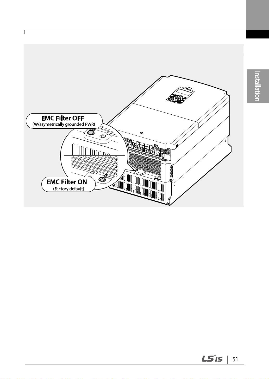
30-75kW
Follow the instructions listed below to disable the EMC filters.
1 Remove the EMC ground cover located at the bottom of the inverter.
2 Remove the EMC ground cable from the right terminal (EMC filter-ON / factory default),
and connect it to the left terminal (EMC filter-OFF / for power sources with
asymmetrical grounding).
51
Installing the Inverter
Note
The terminal on the right is used to ENABLE the EMC filter (factory default). The terminal on the
left is used to DISABLE the EMC filter (for power sources with asymmetrical grounding).

Installing the Inverter
52
UL form
Capacity of applied motor
Braking unit
Non UL type
(A type)
30-37kW
SV037DBH-4
45-55kW
SV075DBH-4, SV075DB-4
75kW
Non UL type
(B type)
30-37kW
LSLV0370DBU-4LN
LSLV0370DBU-4HN
45-75kW
LSLV0750DBU-4LN
UL type
30-37kW
SV370DBU-4U
45-55kW
SV550DBU-4U
75kW
SV750DBU-4U
Brake unit and Brake
resistance
Step 7 Selecting the brake unit (30-75kW models only)
Select the brake unit as following:
Step 8 Re-assembling the Covers and Routing Bracket
After completing the wiring and basic configurations, re-assemble the control terminal cover,
cable routing bracket, and front cover respectively. Note that the assembly procedure may
vary according to the product group or frame size of the product.

53
Installing the Inverter
Items
Check Point
Ref.
Result
Installation
Location/Power
I/O Verification
Is the installation location appropriate?
p.8
Does the environment meet the inverter’s operating
conditions?
p.9
Does the power source match the inverter’s rated input?
p.397
Is the inverter’s rated output sufficient to supply the
equipment?
(Degraded performance will result in certain
circumstances. Refer to 11.8 Continuous Rated Current
Derating on page 431 for details.
p.397
Power Terminal
Wiring
Is a circuit breaker installed on the input side of the
inverter?
p.16
Is the circuit breaker correctly rated?
p.397
Are the power source cables correctly connected to the
R/S/T terminals of the inverter?
(Caution: connecting the power source to the U/V/W
terminals may damage the inverter.)
p.32
Are the motor output cables connected in the correct
phase rotation (U/V/W)?
(Caution: motors will rotate in reverse direction if three
phase cables are not wired in the correct rotation.)
p.30
Are the cables used in the power terminal connections
correctly rated?
p.13
Is the inverter grounded correctly?
p.28
Are the power terminal screws and the ground terminal
screws tightened to their specified torques?
p. 32
Are the overload protection circuits installed correctly
on the motors (if multiple motors are run using one
inverter)?
-
Is the inverter separated from the power source by a
magnetic contactor (if a braking resistor is in use)?
p.16
Are advanced-phase capacitors, surge protection and
electromagnetic interference filters installed correctly?
(These devices MUST not be installed on the output side
of the inverter.)
p.30
Control Terminal
Wiring
Are STP (shielded twisted pair) cables used for control
terminal wiring?
-
Is the shielding of the STP wiring properly grounded?
-
If 3-wire operation is required, are the multi-function
input terminals defined prior to the installation of the
control wiring connections?
p.38
2.3 Post-Installation Checklist
After completing the installation, check the items in the following table to make sure that the
inverter has been safely and correctly installed.
Installing the Inverter
54
Items
Check Point
Ref.
Result
Are the control cables properly wired?
p38
Are the control terminal screws tightened to their
specified torques?
p.21
Is the total cable length of all control wiring < 165ft
(100m)?
p.45
Is the total length of safety wiring < 100ft (30m)?
p.45
Miscellaneous
Are optional cards connected correctly?
-
Is there any debris left inside the inverter?
p.21
Are any cables contacting adjacent terminals, creating
a potential short circuit risk?
-
Are the control terminal connections separated from
the power terminal connections?
-
Have the capacitors been replaced if they have been in
use for > 2 years?
-
Have the fans been replaced if they have been in use
for > 3 years?
-
Has a fuse been installed for the power source?
p.420
Are the connections to the motor separated from other
connections?
-
Note
STP (Shielded Twisted Pair) cable has a highly conductive, shielded screen around twisted
cable pairs. STP cables protect conductors from electromagnetic interference.

55
Installing the Inverter
2.4 Test Run
After the post-installation checklist has been completed, follow the instructions below to test
the inverter.
1 Turn on the power supply to the inverter. Ensure that the keypad display light is on.
2 Select the command source.
3 Set a frequency reference, and then check the following:
• If V1 is selected as the frequency reference source, does the reference change
according to the input voltage at VR?
• If V2 is selected as the frequency reference source, is the voltage/current selector
switch (SW2) set to voltage, and does the reference change according to the input
voltage?
• If I2 is selected as the frequency reference source, is the voltage/current selector
switch (SW2) set to current, and does the reference change according to the input
current?
4 Set the acceleration and deceleration time.
5 Start the motor and check the following:
• Ensure that the motor rotates in the correct direction (refer to the note below).
• Ensure that the motor accelerates and decelerates according to the set times, and
that the motor speed reaches the frequency reference.

Installing the Inverter
56
Note
If the forward command (Fx) is on, the motor should rotate counterclockwise when viewed
from the load side of the motor. If the motor rotates in the reverse direction, switch the
cables at the U and V terminals.
Remarque
Si la commande avant (Fx) est activée, le moteur doit tourner dans le sens anti-horaire si
on le regarde côté charge du moteur. Si le moteur tourne dans le sens inverse, inverser les
câbles aux bornes U et V.
Verifying the Motor Rotation
1 On the keypad, set the drv (Frequency reference source) code in the Operation group to 0
(Keypad).
2 Set a frequency reference.
3 Press the [RUN] key. Motor starts forward operation.
4 Observe the motor’s rotation from the load side and ensure that the motor rotates
counterclockwise (forward).
If the motor rotates in the reverse direction, two of the U/V/W terminals need to be switched.
• Check the parameter settings before running the inverter. Parameter settings may have to
be adjusted depending on the load.
• To avoid damaging the inverter, do not supply the inverter with an input voltage that
exceeds the rated voltage for the equipment.
• Before running the motor at maximum speed, confirm the motor’s rated capacity. As
inverters can be used to easily increase motor speed, use caution to ensure that motor
speeds do not accidently exceed the motor’s rated capacity.
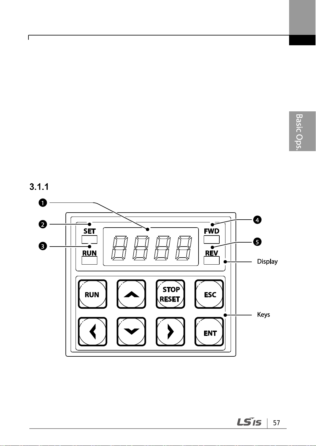
57
Learning to Perform Basic Operations
3 Learning to Perform Basic Operations
This chapter describes the keypad layout and functions. It also introduces parameter
groups and codes, required to perform basic operations. The chapter also outlines the
correct operation of the inverter before advancing to more complex applications. Examples
are provided to demonstrate how the inverter actually operates.
3.1 About the Keypad
The keypad is composed of two main components – the display and the operation (input)
keys. Refer to the following illustration to identify part names and functions.
0.4-22kW Models
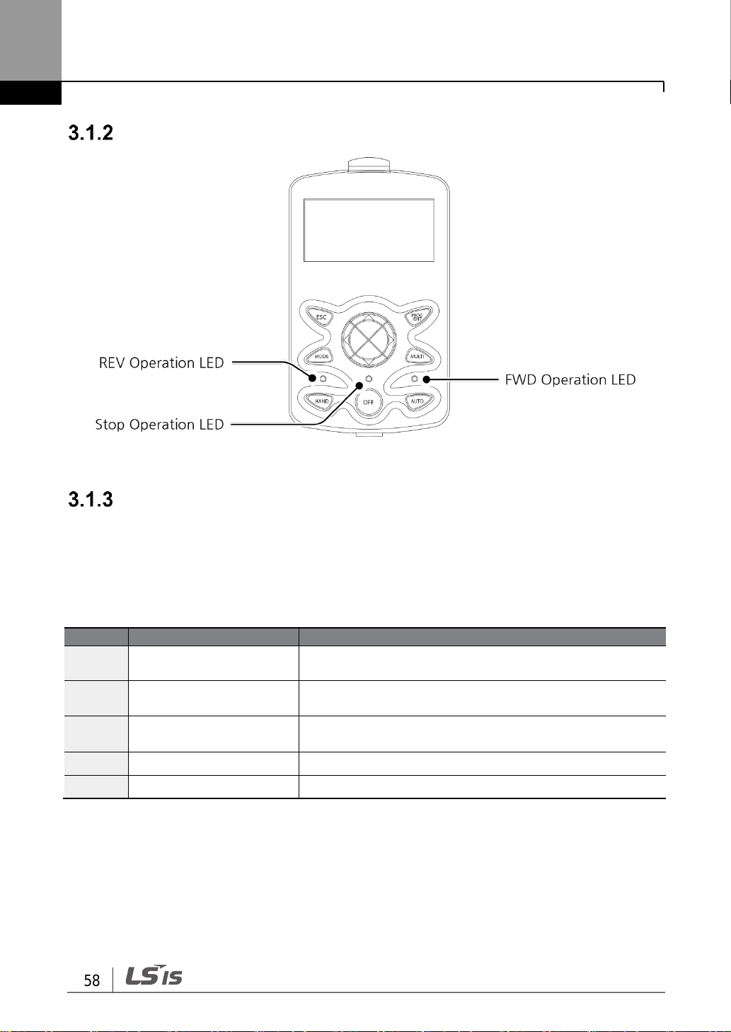
Learning to Perform Basic Operations
58
No.
Name
Function
❶
7-Segment Display
Displays current operational status and parameter
information.
❷
SET Indicator
LED flashes during parameter configuration and when the
ESC key operates as the multi-function key.
❸
RUN Indicator
LED turns on (steady) during an operation, and flashes
during acceleration or deceleration.
❹
FWD Indicator
LED turns on (steady) during forward operation.
❺
REV Indicator
LED turns on (steady) during reverse operation.
30-75kW Models
About the Display
The following table lists display part names and their functions.
3.1.3.1 0.4-22kW Models
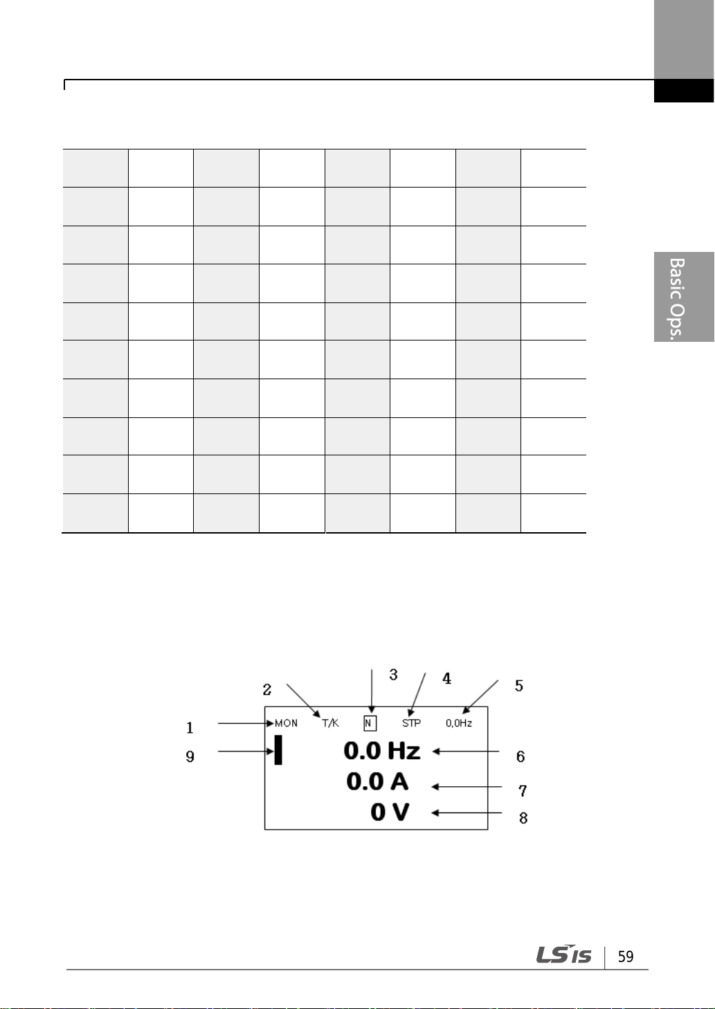
59
Learning to Perform Basic Operations
0 0 a A k K u
U
1 1 b B l L v V 2 2 c C m M w
W
3 3 d D n N x
X
4 4 e E o O y
Y
5 5 f F p P z Z 6 6 g G q
Q
-
-
7 7 h H r
R
-
-
8 8 i I s
S
-
-
9 9 j J t
T
-
-
The table below lists the way that the keypad displays characters (letters and numbers).
3.1.3.2 30-75kW Models
Monitor mode display

Learning to Perform Basic Operations
60
No.
Names displayed in monitor mode
No.
Names displayed in parameter settings
1
Mode
1
Mode
2
Operating/frequency command
2
Group
3
Multi-functional key settings
3
Multi-functional key settings
4
Inverter operation status
4
Inverter operation status
5
Items displayed in the status window
5
Items displayed in the status window
6
Monitor mode display 1
6
Display parameters
7
Monitor mode display 2
7
Available settings range
8
Monitor mode display 3
8
Existing setting values
9
Monitor mode cursor
9
Factory default values
10
Code numbers and names
No.
Name
Display
Description
1
Mode
MON
Monitor Mode
PAR
Parameter Mode
TRP
Trip Mode
CNF
Config Mode
2
Operation
commands
K
Keypad operation command
O
Field Bus communication option operation
command
Parameter settings display
Names displayed in monitor mode and parameter settings
Display details

61
Learning to Perform Basic Operations
No.
Name
Display
Description
A
Application option operation command
R
Internal 485 operation command
T
Terminal operation command
Frequency
commands
K
Keypad frequency command
V
V1 input frequency command
P
Pulse input frequency command
U
Frequency command for UP operation (Up - Down
operation)
D
Frequency command for DOWN operation (Up Down operation)
S
Frequency command for STOP operation (Up Down operation)
O
FBus Option frequency command
J
Jog frequency command
R
Int 485 frequency command
1 ~9, A~F
Multi-step frequency command
3
Multi-
functional key
settings
JOG Key
Keypad JOG operation mode
Local/Remote
Able to select either local or remote operation
UserGrpSelKey
Register or delete user group parameters in
parameter mode
4
Inverter
operation
status
STP
Motor stopped
FWD
Operating in forward direction
REV
Operating in reverse direction
DC
DC output
WAN
Warning
STL
Stall
SPS
Speed Search
OSS
S/W overcurrent protective function is on
OSH
H/W overcurrent protective function is on
TUN
Auto Tuning

Learning to Perform Basic Operations
62
Install a separate emergency stop switch in the circuit. The [STOP/RESET] key on the keypad
works only when the inverter has been configured to accept an input from the keypad.
Key
Name
Description
[RUN] key
Used to run the inverter (inputs a RUN command).
[STOP/RESET]
key
STOP: stops the inverter.
RESET: resets the inverter following fault or failure condition.
,
[▲] key, [▼] key
Switch between codes, or to increase or decrease
parameter values.
,
[◀] key, [▶] key
Switch between groups, or to move the cursor during
parameter setup or modification.
[ENT] key
Used to select, confirm, or save a parameter value.
[ESC] key
A multi-function key used to configure different functions, such
as:
• Jog operation
• Remote/Local mode switching
• Cancellation of an input during parameter setup
Operation Keys
3.1.4.1 0.4-22kW Models
The following table lists the names and functions of the keypad’s operation keys.

63
Learning to Perform Basic Operations
Key
Name
Description
[MODE] Key
Used to switch between modes.
[PROG / Ent]
Key
Used to select, confirm, or save a parameter value.
[UP] key
[DOWN] key
Switch between codes or increase or decrease parameter
values.
[LEFT] key
[RIGHT] key
Switch between groups or move the cursor during parameter
setup or modification.
[MULTI] Key
Used to perform special functions, such as user code
registration.
[ESC] Key
Used to cancel an input during parameter setup.
• Pressing the [ESC] key before pressing the [PROG / ENT]
key reverts the parameter value to the previously set value.
• Pressing the [ESC] key while editing the codes in any
function group makes the keypad display the first code of
the function group.
• Pressing the [ESC] key while moving through the modes
makes the keypad display Monitor mode.
[FWD] Key
Used to operate the motor in the forward direction.
[REV] Key
Used to operate the motor in the reversed direction.
[STOP/RESET]
Key
Used to stop motor operation.
Used to reset the inverter following fault or failure condition.
3.1.4.2 30-75kW Models
The following table lists the names and functions of the LCD’s operation keys.

Learning to Perform Basic Operations
64
Function Group
Name
Keypad
Display
LCD
Display
Description
Operation
0.00
DRV-01
Configures reference frequencies.
ACC
DRV-03
Configures acceleration times.
DEC
DRV-04
Configures deceleration times.
DRV
DRV-06
Used to select operation command.
FRQ
DRV-07
Configures operation frequencies.
ST1
BAS-50
Configures the Step Freq. 1 of the multi-step
frequencies.
ST2
BAS-51
Configures Step Freq. 2 of the multi-step
frequencies.
ST3
BAS-52
Configures Step Freq. 2 of the multi-step
frequencies.
CUR
Monitor Line
Display
(CNF-20~23)
Displays current output current.
RPM
Displays current speed of a load (RPM).
DCL
Displays current DC LINK voltage.
VOL
Displays current output voltage.
NON
TRP Last-1
Displays recent trip history.
DRC
-
Used to select motor operation direction.
Drive
dr
DRV
Configures parameters for basic operations.
These include jog operation, motor capacity
evaluation, torque boost, and other keypad
related parameters.
Basic
ba
BAS
Configures basic operation parameters. These
parameters include motor parameters and
multi-step frequency parameters.
Advanced
ad
ADV
Configures acceleration or deceleration
patterns, frequency limits, etc.
Control
cn
CON
Configures sensorless vector-related features.
Input Terminal
in
IN
Configures input terminal–related features,
including digital multi–functional inputs and
analog inputs.
Output Terminal
ou
OUT
Configures output terminal–related features
such as relays and analog outputs.
Control Menu
0.4-22kW Control Menu
The following table lists the functions groups under Parameter mode.

65
Learning to Perform Basic Operations
Function Group
Name
Keypad
Display
LCD
Display
Description
Communication
cM
COM
Configures communication features for RS485 or other communication options.
Application
ap
APP
Configures functions related to PID control.
Protection
pr
PRT
Configures motor and inverter protection
features.
Motor 2
(Secondary
motor)
m2
M2
Configures secondary motor related features.
The secondary motor (M2) group appears on
the keypad only when one of the multi-function
input terminals (In.65–In.71) has been set to
26 (Secondary motor).
User Sequence
us
USS
Used to implement simple sequences with
various function blocks.
User Sequence
Function
uf
USF
30-75kW Control Menu
The S100 inverter uses 5 modes to monitor or configure different functions. The parameters
in Parameter mode are divided into smaller groups of relevant functions. Press the [Mode]
key to change to Parameter mode.

Learning to Perform Basic Operations
66
Mode Name
LCD Display
Description
Monitor mode
MON
Displays the inverter’s operation status information. In
this mode, information including the inverter’s frequency
reference, operation frequency, output current, and
voltage may be monitored.
Parameter mode
PAR
Used to configure the functions required to operate the
inverter. These functions are divided into 14 groups
based on purpose and complexity.
Trip mode
TRP
Used to monitor the inverter’s fault trip information,
including the previous fault trip history.
When a fault trip occurs during inverter operation, the
operation frequency, output current, and output voltage of
the inverter at the time of the fault may be monitored.
This mode is not displayed if the inverter is not at fault
and fault trip history does not exist.
Config mode
CNF
Used to configure the inverter features that are not
directly related to the operation of the inverter. The
settings you can configure in the Config mode include
keypad display language options, monitor mode
environment settings, communication module display
settings, and parameter duplication and initialization.
The following table lists the 5 display modes used to control the inverter functions.

67
Learning to Perform Basic Operations
3.2 Learning to Use the Keypad
The keypad enables movement between groups and codes. It also enables users to select
and configure functions. At code level, you can set parameter values to turn on or off
specific functions, or decide how the functions will be used. Refer to 8 Table of Functions on
page 302 to find the functions you need.
Confirm the correct values (or the correct range of the values), and then follow the
examples below to configure the inverter with the keypad.
Display Mode Selection (30-75kW models only)
The following figure illustrates how the display modes change when you press the [Mode]
button on the keypad. You can continue to press the [Mode] key until you get to the desired
mode.
User mode and Trip mode are not displayed when all the inverter settings are set to the
factory default (User mode must be configured before it is displayed on the keypad, and
Trip mode is displayed only when the inverter is at fault, or has previous trip fault history).
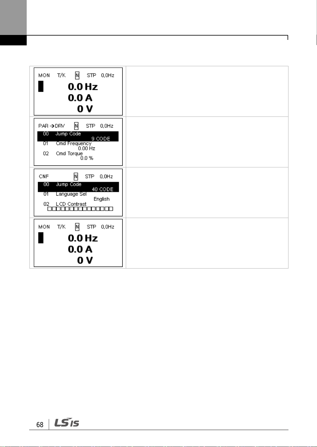
Learning to Perform Basic Operations
68
• When the power is turned on, Monitor mode is
displayed.
• Press the [MODE] key.
• Parameter mode
• Press the [MODE] key.
• Config (CNF) mode
• Press the [MODE] key.
• Monitor mode is displayed again.
Mode selection in factory default condition
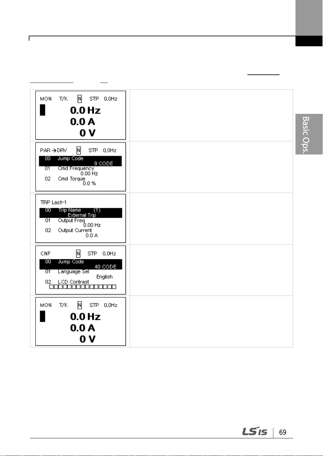
69
Learning to Perform Basic Operations
• When the power is turned on, Monitor mode is
displayed.
• Press the [MODE] key.
• Parameter mode
• Press the [MODE] key.
• Trip mode
• Press the [MODE] key.
• CNF mode
• Press the [MODE] key.
• Monitor mode is displayed again.
Switching between groups when Trip mode is added
Trip mode is accessible only when the inverter has trip fault history. Refer to 4 Learning
Basic Features on page 99 for information about monitoring faults.
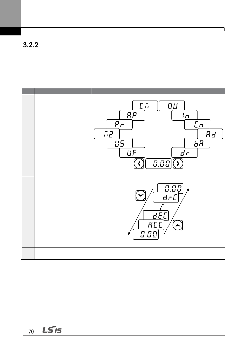
Learning to Perform Basic Operations
70
Step
Instruction
Keypad Display
1
Move to the group you
want using the [◀] and
[▶] keys.
2
Move up and down
through the codes using
the [▲] and [▼] keys until
you locate the code that
you require.
3
Press the [ENT] key to
save the change.
-
Group and Code Selection
Follow the examples below to learn how to switch between groups and codes.
3.2.2.1 0.4-22kW Models
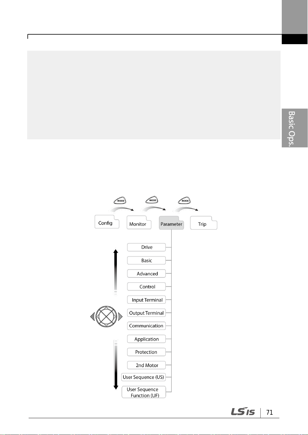
71
Learning to Perform Basic Operations
Note
For some settings, pressing the [▲] or [▼] key will not increase or decrease the code number by
1. Code numbers may be skipped and not be displayed. This is because certain code numbers
have been intentionally left blank (or reserved) for new functions to be added in the future. Also
some features may have been hidden (disabled) because a certain code has been set to disable
the functions for relevant codes.
As an example, if Ad.24 (Frequency Limit) is set to 0 (No), the next codes, Ad.25 (Freq Limit Lo)
and Ad.26 (Freq Limit Hi), will not be displayed. If you set code Ad.24 to 1 (Yes) and enable the
frequency limit feature, codes Ad.25 and 26 will appear to allow the maximum and minimum
frequency limitations to be set up.
3.2.2.2 30-75kW Models (Switching Groups)
Press the [MODE] key to display a specific mode. Modes displayed change in the following
order:
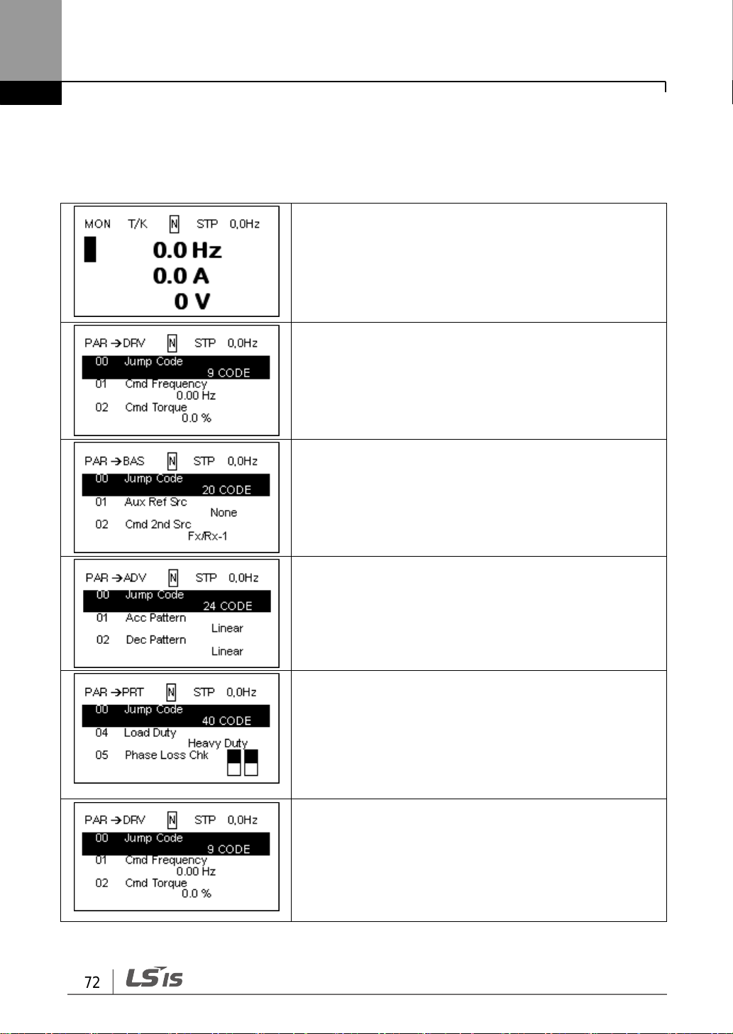
Learning to Perform Basic Operations
72
• When the power is turned on, Monitor mode is
displayed.
• Press the [MODE] key.
• Parameter mode
• Drive group is displayed.
• Press the [▶] key.
• Basic group (BAS)
• Press the [▶] key.
• Advanced group (ADV)
• Press the [▶] key seven times.
• Protection group (PRT)
• Press the [▶] key.
• Parameter mode Drive group (DRV) is displayed again.
Switching between Groups in Parameter Display Mode
After entering Parameter mode from Monitor mode, press the [▶] key to change the display
as shown below. Press the [◀] key to return to the previous mode.
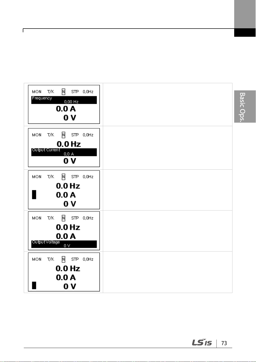
73
Learning to Perform Basic Operations
• When the power is turned on, Monitor mode is
displayed.
• The cursor appears to the left of the frequency
information.
• Press the [▼] key.
• Information about the second item in Monitor mode
(Output Current) is displayed.
• Wait for 2 seconds until the information on the display
disappears.
• Information about the second item in Monitor mode
(Output Current) disappears and the cursor reappears
to the left of the second item.
• Press the [▼] key.
• Information about the third item in Monitor mode
(Output Voltage) is displayed.
• Wait for 2 seconds until the information on the display
disappears.
• Information about the third item in Monitor mode
(Output Voltage) disappears and the cursor appears to
the left of the third item.
• Press the [▼] key twice.
3.2.2.3 30-75kW Models (Code Navigation)
Code Navigation in Monitor mode
In monitor mode, press the [▲], [▼] key to display frequency, the output current, or voltage
according to the cursor position.
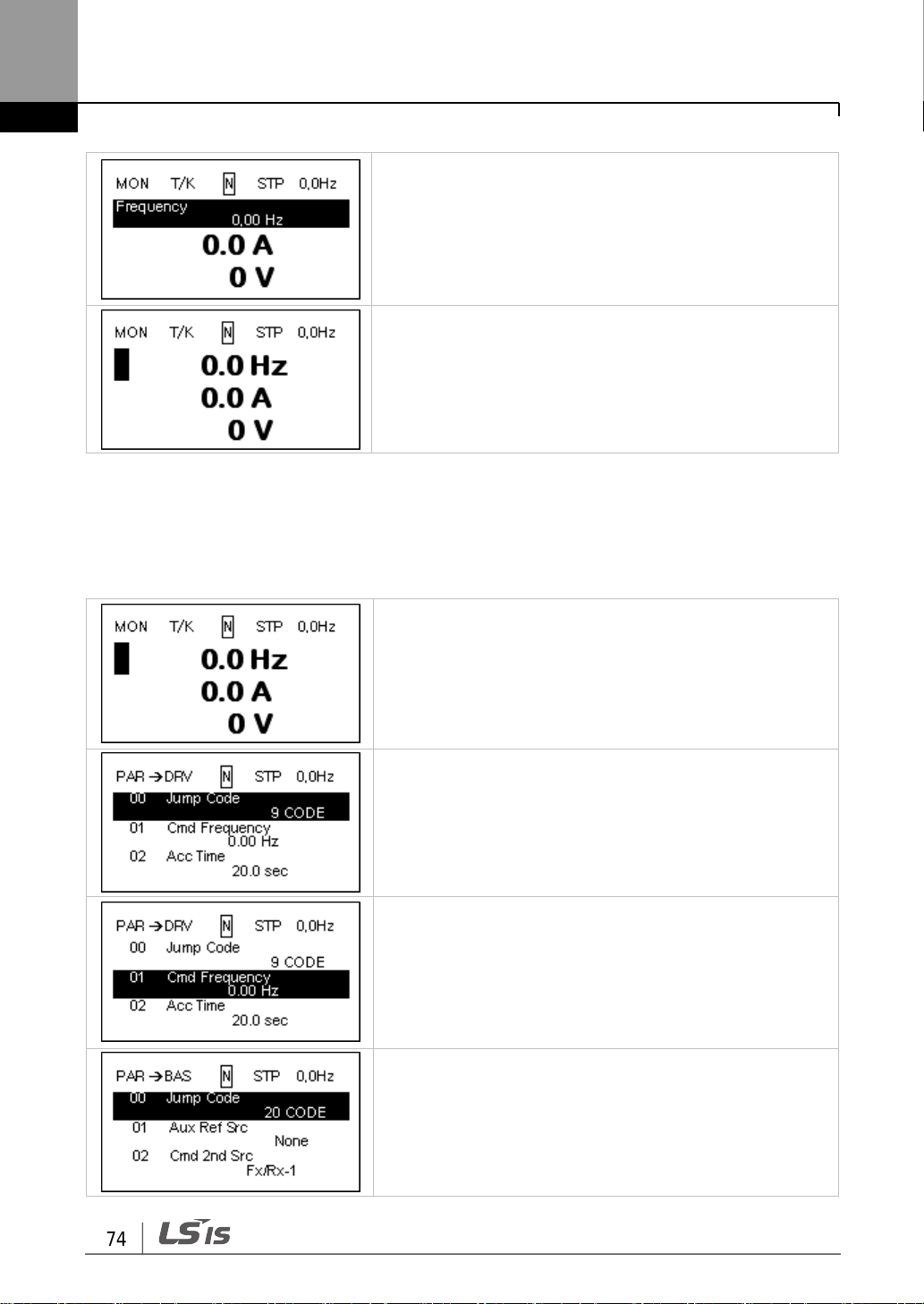
Learning to Perform Basic Operations
74
• Information about the first item in Monitor mode
(Frequency) is displayed.
• Information about the first item in Monitor mode
(Frequency) disappears and the cursor appears to the
left of the first item.
• When the power is on, monitor mode is displayed.
• Press the [MODE] key.
• Drive group (DRV) in Parameter mode is displayed. If
any other group is displayed, press the [MODE] key
until the Drive group is displayed, or press the [ESC]
key.
• Press the [▼] key to move to the second code (DRV-
01) of Drive group.
• Press the [▶] key
• Basic group is displayed.
• Press the [▲] or [▼] key to move to the desired codes
and configure the inverter functions.
Code Navigation in Parameter mode
The following examples show you how to move through codes in different function groups
(Drive group and Basic group) in Parameter mode. In parameter mode, press the [▲] or [▼]
key to move to the desired functions.

75
Learning to Perform Basic Operations
Step
Instruction
Keypad Display
1
Ensure that you are currently at the first code of the Dr ive
group (dr.0).
2
Press the [ENT] key.
Number ‘9’ will flash.
3
Press the [▼] key to display ‘5,’ the first 1s’ place of the group
destination, ’95.’
4
Press the [◀] key to move to the 10s’ place.
The cursor will move to the left and ‘05’ will be displayed. This
time, the number ‘0’ will be flashing.
5
Press the [▲] key to increase the number from ‘0’ to ‘9,’ the
10s place digit of the destination, ’95.’
6
Press the [ENT] key.
Code dr.95 is displayed.
(
%
)5
95
dr.95
dr.0
Navigating Directly to Different Codes
3.2.3.1 0.4-22kW Models
The following example details navigating to code dr. 95, from the initial code in the Drive
group (dr. 0). This example applies to all groups whenever you would like to navigate to a
specific code number.

Learning to Perform Basic Operations
76
• The Drive group (DRV) is displayed in Parameter
mode. Make sure that the fist code in the Drive group
(DRV 00 Jump Code) is currently selected.
• Press the [PROG/ENT] key.
• The Code input screen is displayed and the cursor
flashes. A flashing cursor indicates that it is waiting for
user input.
• Press the [▲] key to increase the number to 9, and
then press the [PROG/ENT] key.
• DRV-09 (Control Mode) is displayed.
• Press the [ESC] key to go back to the initial code of
the Drive group.
3.2.3.2 30-75kW Models
Parameter mode and Config mode allow direct jumps to specific codes. The code used for
this feature is called the Jump Code. The Jump Code is the first code of each mode. The
Jump Code feature is convenient when navigating for a code in a function group that has
many codes.
The following example shows how to navigate directly to code DRV- 09 from the initial code
(DRV-00 Jump Code) in the Drive group.

77
Learning to Perform Basic Operations
Step
Instruction
Keypad Display
1
Select the group and code to setup or
modify parameter settings, and then press
the [ENT] key.
The first number on the right side of the
display will flash.
2
Press the [◀] or [▶] key to move the
cursor to the number that you would like to
modify.
3
Press the [▲] or [▼] key to adjust the
value, and then press the [ENT] key to
confirm it.
The selected value will flash on the display.
4
Press the [ENT] key again to save the
change.
-
Note
• A flashing number on the display indicates that the keypad is waiting for an input from the
user. Changes will be saved when the [ENT] key is pressed while the number is flashing.
The setting change will be canceled if you press any other key.
• Each code’s parameter values have default features and ranges specified. Refer to 8 Table
of Functions on page 302 for information about the features and ranges before setting or
modifying parameter values.
5.)
Setting Parameter Values
3.2.4.1 0.4-22kW Models
Enable or disable features by setting or modifying parameter values for different codes.
Directly enter setting values, such as frequency references, supply voltages, and motor
speeds. Follow the instructions below to learn to set or modify parameter values.

Learning to Perform Basic Operations
78
• Make sure that the cursor is at the frequency
reference item and that the frequency setting is set to
‘Keypad’ in DRV-09.
• Press the [PROG/ENT] key.
• When the cursor is on the frequency reference item,
detailed information is displayed and the cursor
flashes on the input line.
• Press the shift key to go to the desired frequency.
• Press the [▲] key to set the frequency to 10 Hz.
• Press the [PROG/ENT] key.
• The frequency is set to 10 Hz.
3.2.4.2 30-75kW Models
Parameter settings available in Monitor mode
The S100 inverter allows basic parameters to be modified in Monitor mode. The following
example shows how to set the frequency.

79
Learning to Perform Basic Operations
• This is the initial display for Parameter mode.
• Press the [▼] key.
• DRV-01 code is selected.
• Press the [PROG/ENT] key.
• The frequency can be changed at the flashing digit.
• Press the [◀]/ [▶] key to move the cursor to the
desired digit.
• Press the [▲] key to enter 10 Hz, and then press the
[PROG/ENT] key.
• The frequency is changed to 10 Hz.
Parameter settings in other modes and groups
The following example shows how to change the frequency in the Drive group. This
example can also be applied to other modes and groups.

Learning to Perform Basic Operations
80
Step
Instruction
Keypad Display
1
Ensure that you are currently at the first code of the Operation
group, and that code 0.00 (Command Frequency) is
displayed.
2
Press the [▶] key.
You have moved to the initial code of the Drive group (dr.0).
3
Press the [▲] or [▼] key to select code 90 (ESC key
configuration), and then press the [ENT] key.
Code dr.90 currently has an initial parameter value of, 0
(adjust to the initial position).
4
Press the [▲] key to modify the value to 1 (Jog key) and then
press the [ENT] key.
The new parameter value will flash.
5
Press the [ENT] key again to save changes.
-
Note
• If the code dr. 90 (ESC key configuration) is set to 1 (JOG Key) or 2 (Local/Remote), the
SET indicator will flash when the [ESC] key is pressed.
• The factory default setting for code dr. 90 is 0 (move to the initial position). You can navigate
back to the initial position (code 0.00 of the Operation group) immediately, by pressing the
[ESC] key while configuring any codes in any groups.
0.00
dr.0
)
dr.90
!
Configuring the [ESC] Key (0.4-22kW models only)
The [ESC] key is a multi-functional key that can be configured to carry out a number of
different functions. Refer to 4.6 Local/Remote Mode Switching on page 120 for more
information about the other functions of the [ESC] key. The following example shows how to
configure the [ESC] key to perform a jog operation.

81
Learning to Perform Basic Operations
Step
Instruction
Keypad Display
1
Ensure that the first code of the Operation group is selected,
and code 0.00 (Command Frequency) is displayed.
2
Press the [▲] key.
The display will change to the second code in the Operation
group, the ACC (Acceleration Time) code.
3
Press the [ENT] key.
The number ‘5.0’ will be displayed, with ‘0’ flashing. This
indicates that the current acceleration time is set to 5.0
seconds. The flashing value is ready to be modified by using
the keypad.
4
Press the [◀] key to change the first place value.
‘5’ will be flashing now. This indicates the flashing value, ‘5’ is
ready to be modified.
5
Press the [▲] key to change the number ‘5’ into ‘6’, the first
place value of the target number ’16.’
6
Press the [◀] key to move to the 10s, place value.
The number in the 10s position, ‘0’ in ‘06’ will start to flash
7
Press the [▲] key to change the number from ‘0’ to ‘1’, t o
match the 10s place value of the target number’16,’ and then
press the [ENT] key.
Both digits will flash on the display.
8
Press the [ENT] key once again to save changes.
‘ACC’ will be displayed. The change to the acceleration time
setup has been completed.
0.00
acc
5.)
%.0
^.0
)6.0
!^,)
acc
3.3 Actual Application Examples
Acceleration Time Configuration (0.4-22kW models only)
The following is an example demonstrating how to modify the ACC (Acceleration time) code
value (from 5.0 to 16.0) from the Operation group.
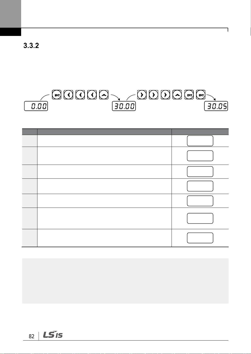
Learning to Perform Basic Operations
82
Step
Instruction
Keypad Display
1
Ensure that the first code of the Operation group is selected,
and the code 0.00 (Command Frequency) is displayed.
2
Press the [ENT] key.
The value, 0.00 will be displayed with the ‘0’ in the 1/100s
place value flashing.
3
Press the [◀] key 3 times to move to the 10s place value.
The ‘0’ at the 10s place value will start to flash.
4
Press the [▲] key to change it to ‘3,’ the 10s place value of
the target frequency, ‘30.05.’
5
Press the [▶] key 3 times.
The ‘0’ at the 1/100s place position will flash.
6
Press the [▲] key to change it to ‘5,’ the 1/100 place value of
the target frequency, ‘30.05,’ and then press the [ENT] key.
The parameter value will flash on the display.
7
Press the [ENT] key once again to save changes.
Flashing stops. The frequency reference has been configured
to 30.05 Hz.
Note
• A flashing number on the display indicates that the keypad is waiting for an input from the
user. Changes are saved when the [ENT] key is pressed while the value is flashing.
Changes will be canceled if any other key is pressed.
• The S100 inverter keypad display can display up to 4 digits. However, 5-digit figures can be
used and are accessed by pressing the [◀] or [▶] key, to allow keypad input.
0.00
0.0)
)0.00
#0.00
30.0)
#),)%
30.05
Frequency Reference Configuration (0.4-22kW models
only)
The following is an example to demonstrate configuring a frequency reference of 30.05 (Hz)
from the first code in the Operation group (0.00).
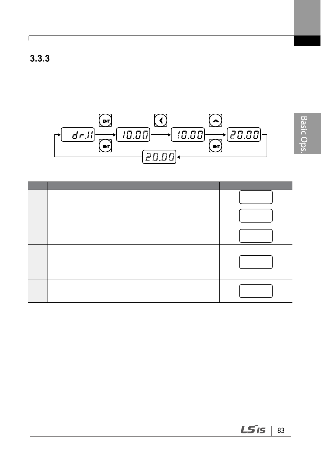
83
Learning to Perform Basic Operations
Step
Instruction
Keypad Display
1
Go to code 11(Jog Frequency) in the Drive group.
2
Press the [ENT] key.
The current Jog Frequency value (10.00) for code dr.11 is
displayed.
3
Press the [◀] key 3 times to move to the 10s place value.
Number ‘1’ at the 10s place position will flash.
4
Press the [▲] key to change the value to ‘2,’ to match the 10s
place value of the target value’20.00,’ and then press the
[ENT] key.
All parameter digits will flash on the display.
5
Press the [ENT] key once again to save the changes.
Code dr.11 will be displayed. The parameter change has been
completed.
dr.11
10.0)
!0.00
@),))
dr.11
Jog Frequency Configuration (0.4-22kW models only)
The following example demonstrates how to configure Jog Frequency by modifying code 11
in the Drive group (Jog Frequency) from 10.00(Hz) to 20.00(Hz). You can configure the
parameters for different codes in any other group in exactly the same way.
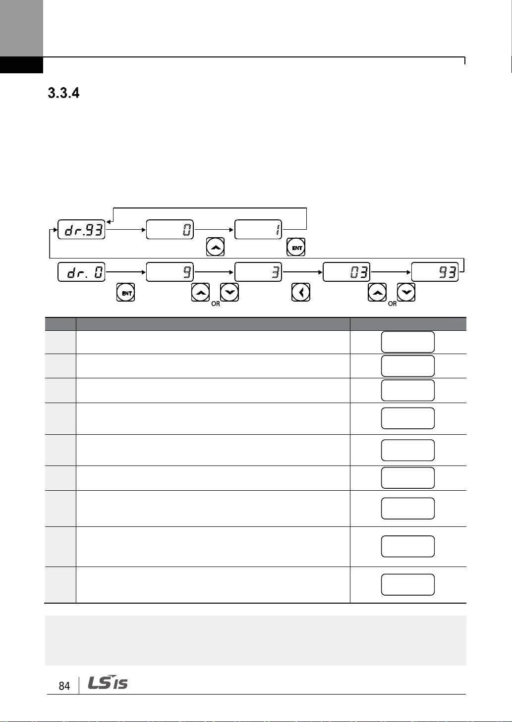
Learning to Perform Basic Operations
84
Step
Instruction
Keypad Display
1
Go to code 0 (Jog Frequency) in the Drive group.
2
Press the [ENT] key.
The current parameter value (9) will be displayed.
3
Press the [q] key to change the first place value to ‘3’ of the
target code, ’93.’
4
Press the [◀] key to move to the 10s place position.
‘03’ will be displayed.
5
Press the [▲] or [▼] key to change the ‘0’ to ‘9’ of the target
code, ’93.’
6
Press the [ENT] key.
Code dr.93 will be displayed.
7
Press the [ENT] key once again.
The current parameter value for code dr.93 is set to 0 (Do not
initialize).
8
Press the [▲] key to change the value to 1 (All Grp), and then
press the [ENT] key.
The parameter value will flash.
9
Press the [ENT] key once again.
Parameter initialization begins. Parameter initialization is
complete when code dr.93 reappears on the display.
Note
Following parameter initialization, all parameters are reset to factory default values. Ensure that
parameters are reconfigured before running the inverter again after an initialization.
dr.0 ( #
)3
(3
dr.93
)
!
dr.93
Initializing All Parameters
3.3.4.1 0.4-22kW Models
The following example demonstrates parameter initialization using code dr.93 (Parameter
Initialization) in the Drive group. Once executed, parameter initialization will delete all
modified values for all codes and groups.
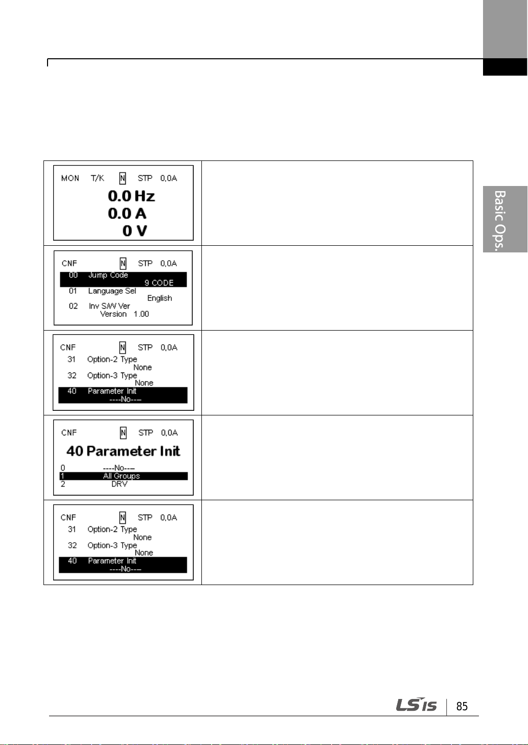
85
Learning to Perform Basic Operations
• Monitor mode is displayed.
• Press the [MODE] key to move to the Config (CNF)
mode.
• Press the [▼] key to go to CNF-40 (Parameter Init).
• Press the [PROG/ENT] key.
• In the list of options, select All Groups, and then press
the [PROG/ENT] key.
• The parameter initialization option is displayed again
when the initialization is complete.
3.3.4.2 30-75kW Models
The following example demonstrates how to revert all the parameter settings back to the
factory default (Parameter Initialization). Parameter initialization may be performed for
separate groups in Parameter mode as well.

Learning to Perform Basic Operations
86
Step
Instruction
Keypad Display
1
Turn on the inverter.
-
2
Ensure that the first code of the Operation group is selected,
and code 0.00 (Command Frequency) is displayed, then
press the [ENT] key.
The first digit on the right will flash.
3
Press the [◀] key 3 times to go to the 10s place position.
The number ‘0’ at the 10s place position will flash.
4
Press the [▲] key to change it to 1, and then press the [ENT]
key.
The parameter value (10.00) will flash.
5
Press the [ENT] key once again to save changes.
A change of reference frequency to 10.00 Hz has been
completed.
6
Refer to the wiring diagram at the bottom of the table, and
close the switch between the P1 (FX) and CM terminals.
The RUN indicator light flashes and the FWD indicator light
comes on steady. The current acceleration frequency is
displayed.
7
When the frequency reference is reached (10Hz), open the
switch between the P1 (FX) and CM terminals.
The RUN indicator light flashes again and the current
deceleration frequency is displayed. When the frequency
reaches 0Hz, the RUN and FWD indicator lights turn off, and
the frequency reference (10.00Hz) is displayed again.
0.0)
)0.00
!),))
10.00
Frequency Setting (Keypad) and Operation (via Terminal
Input)
[Wiring Diagram] [Operation Pattern]
 Loading...