


Right choice for ultimat e yield !
LSIS strives to maximize customer’s profit in gratitude of choosing us for your partner.
Human Machine Interface
XGT PANEL
User
iXP2
iXP2
iXP2
iXP2
Read this manual carefully before
wiring, operating, servicing
easy reach
iXP2 Series
’s Manu al
-08XXA
-10XXA
-12XXA
-15XXA
installing,
or inspecting this equipment.
Keep this manual within
for quick reference.

Safety Precautions
Before using the product…
To use the product safety and effectively, please read this instruction manual thoroughly before use.
► Please keep to the safety precaution, for it to prevent accidents and potential danger from
occurring.
► Safety precaution is classified into ‘Warming’ and ‘Caution’ and their meanings are as follows.
Warning Violating the instruction may result in serious personal injury or death.
Caution Violating the instruction may result in slight personal injury or product
damage.
► The indicated illustrations on the product and in the manual have the fallowing meanings.
Be cautions, for danger may be present.
Be cautions, for there is a possibility of an electric shock.
► After reading the instruction manual, keep it handy for quick reference.
1

Safety Precautions
Design Precautions
Warning
► Install a safety circuit external to the HMI to protect the whole control system in case of
external power supply trouble.
Serious trouble may occur to the entire system due to erroneous output/operation of the HMI.
Design Precautions
Caution
► In/output signal or communication cable should be at least 100mm apart from High-
voltage/power wires.
Otherwise, it may cause erroneous output/operation.
Installation Precautions
Caution
► Use the HMI in an environment that meets the general specification contained in this
manual or datasheet.
Otherwise, it could result in electric shock, fire, erroneous operation or deterioration.
► In case of much vibration in the installed environment, be sure to insulate the HMI from
direct vibration.
Otherwise, it could result in electric shock, fire, erroneous operation.
► Be sure not to let foreign substances such as conductive debris inside the product.
Otherwise, it could result in electric shock, fire, erroneous operation.
► Do not touch the conductive part of the HMI. It may cause an electric shock,
which may cause malfunction.
2

Safety Precautions
Warning
Wiring Precautions
► Be sure to turn off the HMI and external power before wiring.
Otherwise, it may result in an electric shock or damage to the product.
Caution
► Wire correctly by checking each of the product’s rated voltage and terminal layout.
Otherwise, it may result in fire, electric shock or erroneous operation.
► Tighten terminal screws with specified torque when wiring.
If terminal screws are loose, it may result in short circuits, fire or erroneous operation.
► Use the exclusive HMI 3-type grounding for the FG terminal.
If not grounded, it may result in erroneous operation.
► Be sure not to let any foreign substances such as wiring debris inside the module.
Such debris may cause fire, damage or erroneous operation.
► Tighten the crimp terminal to the specified torque, and crimp the external
connection connector using the specified tool or solder it correctly.
3

Safety Precautions
Warning
Startup and Maintenance Precautions
► Do not touch the terminals while power is on.
Otherwise, it may cause electric shock or erroneous operation.
► Turn off the HMI and external power when cleaning or tightening the terminal.
Otherwise, it may cause electric shock or erroneous operation.
► Do not charge, disassemble, heat, short circuit, solder, etc. other battery.
Mishandling the battery may cause overheating, crack, fire and may result in injury or fire.
Caution
► Do not disassemble PCB from the product case or modify the product.
Otherwise, it may result in fire, electric shock or erroneous operation.
► When mounting or remov ing the HMI f rom the pa nel, be s ure to sh ut off all power
being used by the system . It may cause el ectr ic shock , malfu nction .
► Use cellular phone or walky-talky at least 30cm away from the HMI.
Otherwise, it may result in erroneous operation.
Disposal Precaution
Caution
► When disposing of this product or battery, treat it as industrial waste.
Otherwise, it may cause poisonous pollution or explosion.
4

Revision History
Revision History
Version Date Contents Revised location
V1.0 ‘18.01 First Edition -
※ The number of User’s manual is indicated the right side of the back cover.
ⓒ LSIS Co., Ltd2018 All Rights Reserved.
5
Contents
Chapter 1 General Introduction ...................................................................... 1-1~1-6
1.1
How to use the Instruction Manual ........................................................................................................ 1-1
1.2
Feature .................................................................................................................................................. 1-2
1.3
Terminology .......................................................................................................................................... 1-5
1.4
Specification of product name ............................................................................................................... 1-6
Chapter 2 System Configuration ....................................................................... 2-1~2-4
2.1
Part Names ........................................................................................................................................... 2-1
2.2
System Configuration ............................................................................................................................ 2-4
Chapter 3 Standard Specification...................................................................... 3-1~3-4
3.1
General Standards ................................................................................................................................ 3-1
3.2
Function Standards ............................................................................................................................... 3-3
Chapter 4 Installation and Wiring .................................................................... 4-1~4-9
4.1
Installation ............................................................................................................................................. 4-1
4.1.1 Installation environment............................................................................................................... 4-1
4.1.2 Notice in handling ........................................................................................................................ 4-3
4.1.3 Precautions for panel installa tion ................................................................................................ 4-3
4.2
Wiring .................................................................................................................................................... 4-7
4.2.1 Power Wiring ............................................................................................................................... 4-6
4.2.2 Ground Wiring ............................................................................................................................. 4-9
Chapter 5 XGT Panel Menu Explanation.......................................................... 5-1~5-39
5.1
Settings .................................................................................................................................................. 5-2
5.1.1 Backlight Setting .......................................................................................................................... 5-2
5.1.2 Touch Setting .............................................................................................................................. 5-4
5.1.3 DateTime Setting ........................................................................................................................ 5-5
5.1.4 Environment Setting ................................................................................................................... 5-6
5.1.5 Ethernet Setting ........................................................................................................................ 5-14
5.1.6 Buzzer Setting ........................................................................................................................... 5-15
5.1.7 Sound Setting ............................................................................................................................ 5-16
5.1.8 XP-Remote Setting ................................................................................................................... 5-17
5.2
Diagnostics .......................................................................................................................................... 5-18
5.2.1 Screen Diagnostic ..................................................................................................................... 5-19
5.2.2 Touch Diagnostic ...................................................................................................................... 5-20
5.2.3 Backup Memory Diagnostic ...................................................................................................... 5-21
6

Contents
5.2.4 Flash Memory Diagnostic .......................................................................................................... 5-22
5.2.5 USB Memory Diagnostic ........................................................................................................... 5-23
5.2.6 Serial Diagnostic ....................................................................................................................... 5-24
5.2.7 SD Card Diagnostic ................................................................................................................... 5-26
5.3
PLC Information ................................................................................................................................... 5-27
5.3.1 PLC Communication Setting ..................................................................................................... 5-28
5.3.2 Connection Information ............................................................................................................. 5-29
5.3.3 PLC Information ........................................................................................................................ 5-30
5.3.4 History of PLC error .................................................................................................................. 5-30
5.3.5 PLC Operation Mode Conversion History ................................................................................. 5-31
5.3.6 History of power off of PLC ....................................................................................................... 5-31
5.3.7 PLC System History Information ............................................................................................... 5-32
5.3.8 N:1 Setting................................................................................................................................. 5-33
5.3.9 Program Monitor ....................................................................................................................... 5-34
5.4
XGT Panel Update .............................................................................................................................. 5-35
5.5
Storage Function ................................................................................................................................ 5-36
5.5.1 Overview .................................................................................................................................... 5-36
5.5.2 Downloading a project using a storage device .......................................................................... 5-37
5.5.3 Uploading a project using a storage device ............................................................................... 5-38
5.5.4 Updating the device using a storage device .............................................................................. 5-39
Chapter 6 Backup files by using Storage Devices.…………........................... 6-1~6-7
6.1
Path Structure in case of File Backup.................................................................................................... 6-1
6.2
Operation Setting when there is no s pace for Backup ........................................................................ 6-5
6.3
Monitoring Connection Status of External Storage Equipment .............................................................. 6-6
Chapter 7 Maintenance ..................................................................................... 7-1~7-3
7.1
Maintenance .......................................................................................................................................... 7-1
7.2
Daily Maintenance ................................................................................................................................ 7-1
7.3
Periodical Maintenance ........................................................................................................................ 7-2
Chapter 8 EMC Standard Certification……………………………....................... 8-1~8-3
8.1
Requirement for EMC Standard Certification ........................................................................................ 8-1
8.1.1 CE Standard Certification ............................................................................................................. 8-1
8.1.2 KC Standard Certification ............................................................................................................. 8-2
8.2
Requirement for Low Voltage Command Suitability............................................................................. 8-2
8.2.1 Standard Certification for XGT Panel ........................................................................................... 8-2
8.2.2 Selection of XGT Panel ................................................................................................................ 8-2
7

Contents
Appendix 1 Troubleshooting.............................................................. App1-1~App1-25
1. Type of Problems ................................................................................................................................App 1-1
2. Problems when Starting ......................................................................................................................App 1-2
3. Problems after the Monitor on.............................................................................................................App 1-4
4. Display Problems of Figure and Object ..............................................................................................App 1-6
5. Communication Problems ..................................................................................................................App 1-9
6. USB Removal of Memory Card........................................................................................................App 1-10
7. External memory recognition………………….................................................................................App 1-11
8. Touch recognition……………………………….................................................................................App 1-11
9. Error Message during Execution of Programs.................................................................................App 1-12
Appendix 2 Dimensions ................................................................... App 2-1~App2-4
1. iXP2-08XX…................................................................................................................................... App 2-1
2. iXP2-10XX....................................................................................................................................... App 2-2
3. iXP2-12XX....................................................................................................................................... App 2-3
4. iXP2-15XX…................................................................................................................................... App 2-4
Appendix 3 Warranty and Environmental Policy............................................. App 3-1
1. Warranty contents........................................................................................................................... App 3-1
2. Environmental Policy...................................................................................................................... App 3-1
8
1-1
Chapter 1 General Introduction
Chapter 1 General Introduction
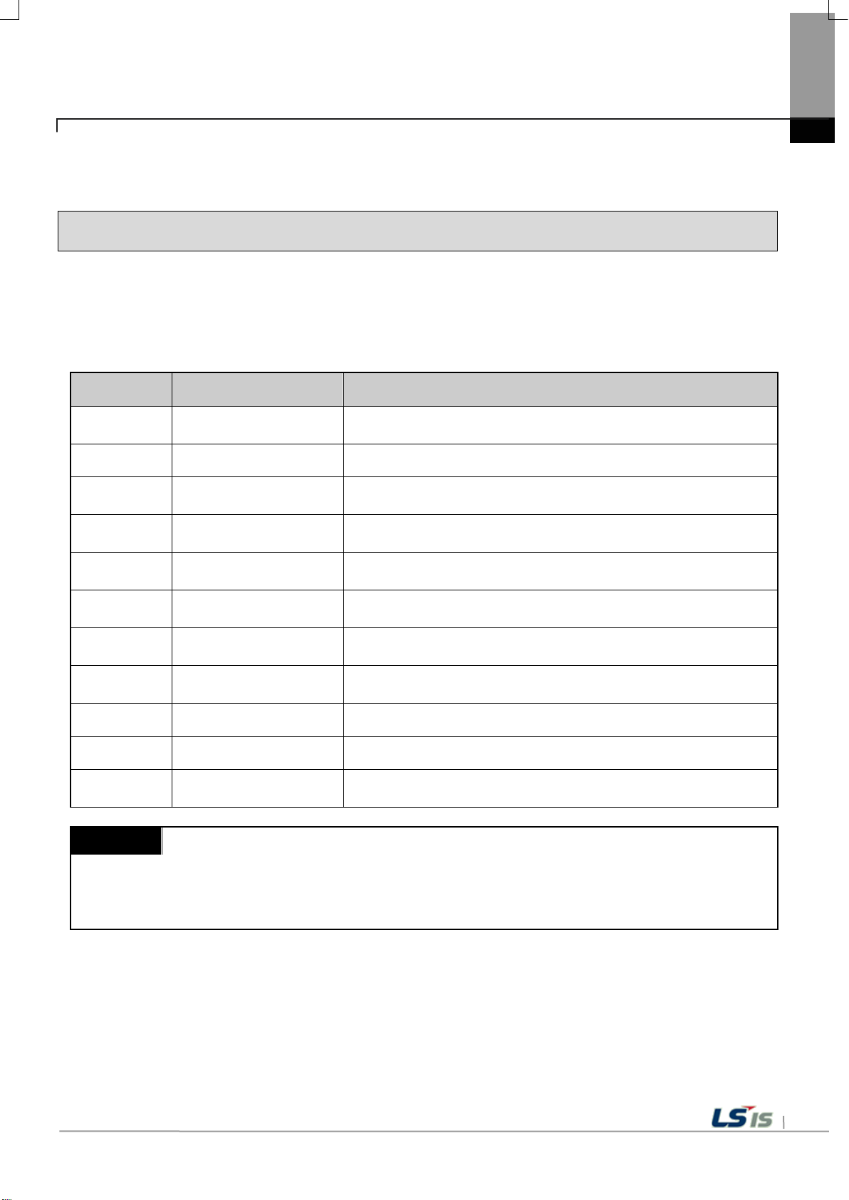
1.1 How to use the Instruction Manual
This instruction manual provides information such as specification, how to use, etc., of the product
needed to operate iXP2 series of XGT Panel.
The user manualPanel.el.provides information s
Sequence Category Contents
Chapter1 General Introduction
Chapter2 System Configuration
Chapter3
Chapter4
Chapter5
Chapter6
Chapter7 Maintenance
Chapter8
Appendix 1 Troubleshooting It describes a variety of error contents and measure.
Appendix 2 Dimensions It describes the dimension of XGT Panel.
Appendix 3
Remark
This manual does not explain XP-Builder and PLC connection. Please refer to the related manual for
the function.
Standard
Specification
Installation and
Wiring
XGT Panel Menu
Explanation
Backup files by using
Storage Devices
EMC Standard
Certification
Warranty and
Environment Policy
It describes this manualprovides information suctdescribes
this manual.
It describes feature and system configuration of each XGT Panel.
It describes XGT Panelnd system configuration of each XGT
Panel.
It describes an installation, wiring and caution for
reliability of PLC system.
It describes XGT Panel Menu.
It describes the way to backup recipe, logging and etc.
files by using storage devices.
It describes inspection category and method for long normal
operation of PLC system.
It describes system configuration for EMC standard.
-

1-2
RS-232C/Ethernet
US B Me mor y
USB Loadder
Cable
XP-Builder
Chapter 1 General Introduction
1.2 Feature
The XGT Panel has the following features.
(1) Various types of external interfaces
(a) Supporting various device of USB, Ethernet, it maximizes the customer’s usability.
(b) PLC, Inverter, and other control devices.
• RS-232C , RS-422/485 and Ethernet (10Base-T / 100Base-TX / 1000-Base-T) communication with the control device.
(2) Based on Windows CE
(a) Adopted Mi crosoft Company's WEC 7
• Windows Embedded Compact 7 has been used.
Windows Embedded Compact 7 Features
(b)
• It provides stable software capacity by using Microsoft Company’s platform.
• It can process diverse function simultaneously.
• It provides diverse interface including Ethernet, USB.
• The user interface including mouse and keyboard can be connected.
• It has high flexibility like computer software.
• Fast reaction is available when adding new equipment.
• Wide data sharing and management with upper system is available.
(3) Projects in various ways send
(a) Project transmission using RS-232C communi cation
(b) Project transmission using Ethernet port
(c) Project transfer u sing USB Loadder cable
(d) Project transmission using USB memory

1-3
Chapter 1 General Introduction
(4) Providing a high-quality screen
(a) It adopts high-performance liquid crystal display (LCD) to provide high pi cture quality and sharpness.
• It adopts thin film tran sistor liquid cry stal display (TFT LCD ) which can display 24bit color.
(b) Supports various graphic formats.
• Su pports 1024 X 768 graphic formats precise and realisti c representation.
• Su pports behavior for animations (GIF).
(c) Supports external di splay output.
• HDMI output is supported.
• Duplicate mode and extended mode enable screen output in various configurations.
(5) Application of CAP tou ch panel
(a) Touch sen sitivity is improved by applying electrosta tic touch panel.
(b) Multi-touch and gesture functions.
(c) Various types of touch setting function can be used accordi ng to user's work environment.
(6) Provides multilingual and various fonts
(a) Supports multi-langu age languages.
• It uses the method of transferring the window / use r font used on the computer to XGT Panel .
• No separate multilingual language development is required.
• Multilingual la nguage support is an advantage of Windows CE.
(b) Supports simultaneou s display of 12 language s.
• Simultaneous di splay in 12 languages 12 languages.i
• You can swit ch languages 2 language s 12 languages.indow s CE.ed on t
(c) Various fonts are provid ed.
• Windows / user fonts can be used, so various expression s are possible.
• You can freely adjust font siz e and shape.

1-4
Chapter 1 General Introduction
(7) Providing various convenie nce functions
(a) Various alarm functi ons are provided.
• The history alarm can be divided into several alarm groups and alarm list, and the desired alarm can be displayed on
the screen with the alarm explo rer.
• The flow alarm displays the current alarm at the bottom of the screen.
• The system alarm is displayed when a criti cal problem occurs during operation.
(b) It provides the logging function.
• It provides periodic logging that works repeatedly according to time and device status and conditional logging
according to device conditio ns.
• Backup provide s up to 1 Mbyte.
• You can backup to a USB.
• Backup data i s stored in Excel format, so you can u se it conveniently .
(c) It provides a recipe function.
• It provides read / write function.
• One recipe provides up to 100 double words ( DWORD), 16 blocks.
• You can backup to a USB storage device.
• Backup data i s stored in Excel format, so you can u se it conveniently .
(d) It provides scheduler function.
• Up to 32 schedulers can be set.
(e) It provides printing function.
• Screen / ala rm printing functi on.
• Print out the printout.
(f) It provides scripting capabilities.
• User-written scripts provide more flexibility.
• Global / Object / Screen display.
(8) Stable products conforming to international standards
(a) CE, KC (Electromagnetic compatibility registratio n) standard acquisiti on
1-5
Chapter 1 General Introduction
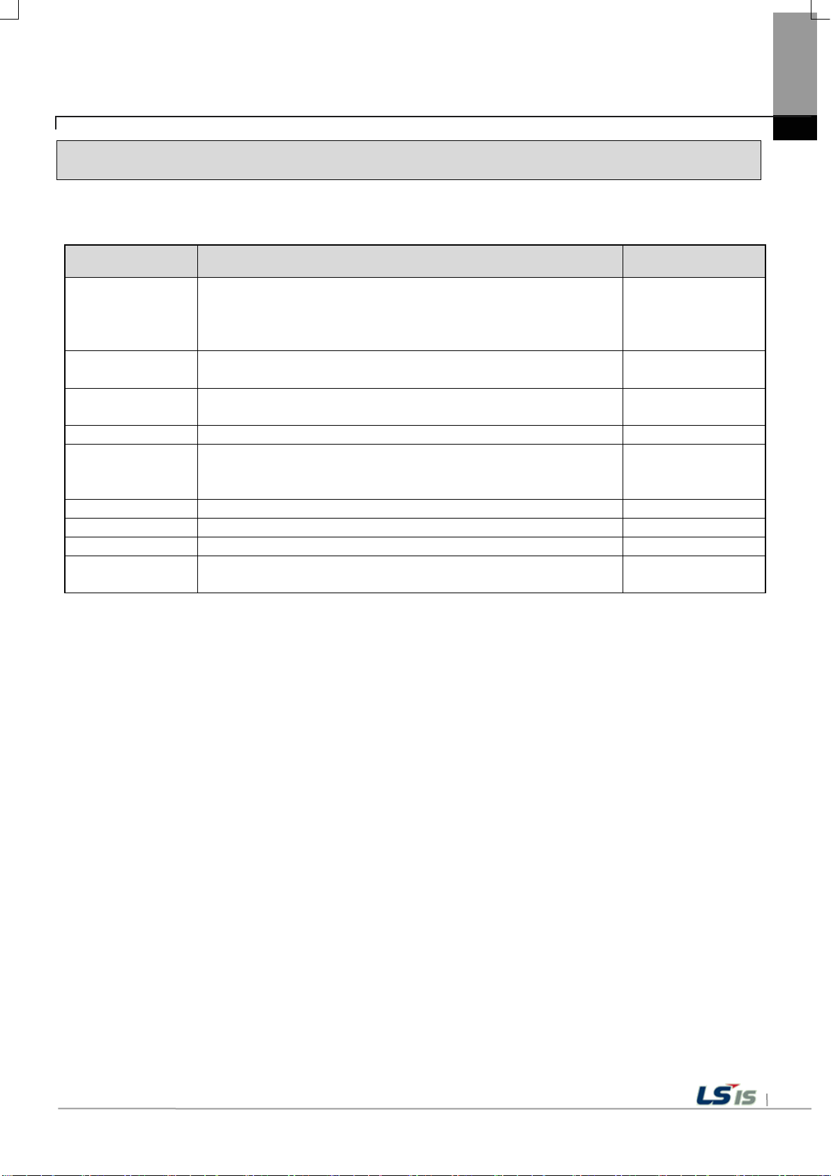
1.3 Terminology
It describes terms used in this manual.
Term Definition Remarks
A standard element that has a specified function which
Module
Unit
PLC system
XP-Builder Software used to write and edit the project. -
XP-Manager
XP-Remote Software used to remote monitor and control the XGT Panel
Cnet module Computer Link FEnet module Fast Ethernet Network -
RTC
configures the system.
Devices such as I/O board, which inserted onto the mother
board or base unit..
A single module or group of modules that perform an
independent operation as a part of PLC system.
System consisted of PLC and peripheral device which can be
controlled by user program.
It is the software for edition, download, monitoring to
realize data communication between XGT Panels through XP
Link with online control function.
Abbreviation of tworkte monitor and It is used to call
general IC that contains clock function.
Ex) CPU module,
Power Module,
I/O module
Ex) Basic unit,
Extension unit
-
-

1-6
iXP2
-
(A)
(B)(C)(D)
Division
Sign
Contents
Remarks
08
21 cm (8.4”)
-
10
26 cm (10.2”)
-
12
31 cm (12.1”)
-
15
38 cm (15.0”)
-
0
WinCE 7.0 (Core)
-
1
WinCE 7.0 (Pro)
-
RS-232C, RS-422/485,
Ethernet
(D) Power supply
A
AC 100 ~ 240V
-
Chapter 1 General Introduction
1.4 Standard of product name
It describes terms used in this product names.
(A) LCD type
(B) O/S type
(C) Communication 0 Standard type

2-1
1
2
3
4
1) Display the power statu s of the device
Display using high brightness blue LED
1) USB Host 1ch
2) USB Device 1ch
Chapter 2 System Configuration
Characteristic of each iXP2 series and its system configuration are as follow ;
2.1 Part Names
1. iXP2-08XX / 10XX / 12XX / 15XX
Chapter 2 System Configuration
No. Name Function
1 Power LED
2 Front USB
Front Part
3
4 Panel fixing portion 1) Fix ing XGT Panel to Panel with Bracket
※
1) P-CAP touch panel: U ser touch input
2) LCD: Display

2-2
iXP2-1200A
5
7
8
9
10
6
11
422/485 connector
ON
1 2 3 4
A
B
RS-422/485 termination resistance On
(Default)
System reset switch. Pressing the switch will reset the system.
Chapter 2 System Configuration
No. Name Function
PE connector
5
6 Power Connector
Cable fixing hole
7
RS-
8
PE connection
Power and PE connections
Fixing Cable s
RS-422/485 (COM3): PLC / Contr ol device co mmunicati on
<Setting switch>
9
Battery cover,
Reset switch,
Backup battery,
Setting switch
No. 1/2
A Side.
B Side. RS-422/485 termination resistance Off
A Side.
O/S Download
No. 3
B Side.
Nand Flash booting(Default)
A Side. Backup Battery On
No. 4
B Side. Backup Battery Off(Default)
<Reset S/W>
10
11
SD Card Logging / Recipe / Alar m / Project data backup and transfer
Gasket Protecting from water and dust

2-3
17
12 13 14 15 1816
1) USB memory connection: Lo gging / Recipe / Ala rm / Project data
3) Printer connection: Print function
Ethernet: 10Base-T / 100Base-TX
4) PLC / control device c ommunication
Ethernet: 10Base-T / 100Base-TX / 1000Base-T
4) PLC / control device c ommunication
Thanks to anti-drop lock, the Panel can be installed in a panel by a single
operator.
Note
(1) The surface of the touch panel must be kept clean at all times.
(5) Please refer to Chapter 10 for installation details.
Chapter 2 System Configuration
No. Name Function
12
13
14
15
16 Ethernet terminal
17
18
Audio-Out Stereo audio output
HDMI Clone mode display output
USB host
Ethernet terminal
RS-232C connector RS-232C (COM2): PLC / Control device communication
Anti-drop lock
Backup and transfer
2) User Interface Connection: Use mouse / Keyboard
1) Project data transmission
2) Logging / Recipe / Al arm / Screen Data Backu p
3) Upgrading the device software
1) Project data transmi ssion
2) Logging / Recipe / Al arm / Screen Data Backup
3) Upgrading the device software
- Foreign objects (water, oil, etc.) on the touch panel may cause malfunction.
(2) Touching the front of the touch panel may cause malfunction.
- Be careful that conductive objects do not touch the touch panel.
(3) The switch No. 1/2 o f the setting swi tch must be set in th e same direction.
- I f switches 1 and 2 are set in different di rections, communicati on problems may occur.
(4) Refer to the communication manual for details on communication conne ction.

2-4
RS-232C/Ethernet
US B Me mor y
USB Loadder
Cable
XP-Builder
US B Me mor y
SD
Card
Note
(1) It is recommended to u se Ethernet rathe r than RS-232C.
(3) Refer to XP-Builder manual for project transfer method.
Chapter 2 System Configuration
2.2 System Configuration
To use XGT Panel, y ou must create project data in XP-Builder and tran sfer it to XGT Panel.
By default, you can conne ct to XGT Panel u sing USB.
Basically, it can be connected with XGT Panel using RS-232C method.
The maximum communication speed is 115,200 [bps].
With Ethernet, project data can be transferred quickly .
If the LAN environment i s established as shown below, you can use it more easily and e ffectively.
1: 1 connection is also supported in case LAN (LAN) environment i s not established.
If project data can not be transferred using communication, y ou can transfer data u sing USB storage devi ce or SD card.
Please refer to Chapter 5 and XP-Builder User's Guide for more information.
(2) Refer to the communication manual for how to make the Ethernet cable.

3-1
Related
Standards
Ambient operating
temperature
Square wave
Impulse noise
AC: ± 1,500V
DC: ± 1,000V
LS Industrial
Standard
Electrostatic
Immunity
Emissions
Communication
interface
2kV (LG)
1 kV (LL)
1kV (LG)
0.5 kV (LL)
Chapter 3 Standard Specification
3.1 General Standards
General specifications of XGT Panel are as follows.
No. Item standard
Chapter 3 Standard Specification
1
2 Storage temperature -20 ° C ~ + 60 ° C 3 Operating humidity 10∼85%RH, non-condensing. 4 Storage humidity 10∼85%RH, non-condensing. -
Occasional vibration Count -
frequency acceleration amplitude
5≤f<9 Hz - 3.5mm
9≤f≤150
Hz
5
6 Shock endurance
Vibration
resistance
frequency acceleration amplitude
5≤f< 9
9≤f≤150
* Maximum shock acceleration: 147
* Duration time: 11
* Pulse wave: half sine pulse (3 times each in X, Y and Z directions)
9.8
Continuous vibration
Hz
- 1.75mm
Hz
4.9
ms
0 ° C ~ + 50 ° C -
m/s2 -
m/s2 -
m/s2 (15G)
10 times each
in X, Y and Z
direction
IEC 61131-2
IEC 61131-2
Discharge
Electromagnetic
7
8 Environment Free from corrosive gases and excessive dust -
9 Operating height Below 2,000m (6,562ft) 10 Pollution degree 2 or less 11 Cooling method Natural Air-Cooling -
Noise
Immunity
Radiated
Fast
Transient
/ Burst noise
Surge
Category Power mod ule Communication interface
Voltage 2 kV 1 kV
Category AC power DC power supply
Voltage
± 4 kV (contact discharge), ± 8 kV (air discharge)
80 ~ 1,000 MHz, 10 V / m
1 kV
IEC 61131-2
IEC 61000-4-2
IEC 61131-2
IEC 61000-4-3
IEC 61131-2
IEC 61000-4-4
IEC 61131-2

3-2
Note
body and the operation of the video display device connected to
Chapter 3 Standard Specification
(1) IEC(International Electro technical Commission)
- International private gr oup facilitating int ernational cooper ation of electric/elect ronic standardi zation, issuing
international standards and operating the compliance evaluation systems.
(2) Pollution degree
- As a n index representing the pol lution degree of an environm ent to determine the insulation of a device,
pollution degree 2 generally means the status generating non-conductive contamination. However, it also
contains the status generating temporarily conduction due to condensation.
(3) Noise Immunity
- The noise noise standard is the standard of the HMI
HDMI is not guaranteed.

3-3
Item
iXP2-08XXA
iXP2-10XXA
iXP2-12XXA
iXP2-15XXA
Display type
TFT color LCD
Color indication
Bottom: 60 deg.
Bottom: 75 deg.
Bottom: 80 deg.
Capacitive Touch
Magnetic Buzzer (85dB)
Processor
1GHz, Dual core
Operating RAM
1GB
Backup data
About 3 years (25℃)
1 x 10Base-T / 100Base-TX, 1 x 10Base-T / 100Base-TX / 1000Base-T
3 x USB 2.0 (Front x 1, Rear x 2)
1 x USB 2.0 (Send / Receive front, PC and project data etc.)
RS-232C
1 x RS-232C (DSUB 9 / Male type)
RS-422/485
1 x RS-422/485 (Terminal Block)
Multi-language
Can display 12 languages simultaneously
Animation
GIF format support
Recipe
Support
Script Launcher
Standard Certification
228.5 x 158.5
259.0 x 201.0
301.5 x 227.5
383.5 x 282.5
Power consu mption ( W)
25
25
30
30
Weight (Kg)
1.87
2.35
3.0
4.6
3.2 Function Standards
The functional specifications of XGT Panel are as follows.
Chapter 3 Standard Specification
Screen size
Display resolution
Indication degree
Backlight
Backlight lifetime
T ouch panel
Audio otput
Memory
Battery life
Video Output
Ethernet
USB host
USB device
Flash
Backup RAM
8.4 "
800 x 600 1024 x 768
Right and left: 80 deg.
Top: 80 deg.
10.4 " 12.1 " 15 "
24-bit color (16.7M colors)
Right: 75 deg.
Top: 75 deg.
LED method, automatic On / Off support
Date / Time data, Logging / Alar m / Recipe data, Non-volatile devices
Right and left: 80 deg.
Top: 80 deg.
50,000 hour
1GB
1 Mbyte
1 x HDMI
Data logging
Protection standard
Dimensions (mm)
Panel Cut (mm)
Support
Support
CE, KC, UL
IP66
240 × 180 × 60 271 x 212 x 60 313 × 239 × 60 395 × 2 94 × 66
Power A(AC100~220V), D(19.2~28.8V)

3-4
Note
more details on installation, See Chapter 4.Installation and Wiring.
Chapter 3 Standard Specification
(1) Caution in power connection
- W ith AC power a pplied to DC power dev ice, it ma y cause product damage or fire. Please pay a special
attention to connection.
(2) PE Connection
- For the device PE, please use PE terminal.
(3) Battery discharge-prevention DIP switch
- In order to prevent the battery discharge, turn off the DIP switch No.4.
To use backup function, please turn on DIP switch No. 4.
(4) Battery Operation and Life
- Batter y is used for RT C (date/time) whe n the power of device is off . Battery is not c onsum ed with power
applied.
(5) LCD Backlight Replacement
- Please replace LCD if you want to replace LCD backlight.
(6) Protection standard
- XGT Panel is designed by IP66 Standard in front par t s . Ingr ess Protec ti on( IP) is based on the IEC 60529
Standard for degr ees of protection provided b y enclosures. But XGT Pan el does not guarantee fr om all
installation environm ent. When i nstalling pa nels, m ake sure that dust an d mois ture are not bro ught in. For

4-1
Chapter 4. Installation and Wiring
Chapter 4 Installation and Wiring
4.1 Installation
4.1.1 Installation environment
This machine has high reliability regardless environment. But for reliability and stability, be careful the followings
(1) Environment condition
(a) Install at the panel which can protect this machine from water and dust. XGT Panel is designed by IP66
Standard in front parts and IP20 Standard in rear parts.
(b) Install at the place where impact and vibration is not continuously applied. XGT Panel is designed to
meet IEC standard (IEC 61131-2).
(c) Do not expose this machine to direct light.
(d) Do not install at the place where rapid temperature change can occur. Moisture by rapid temperature
change can cause malfunction and damage.
(e) This machine should be installed within 0~50°C, otherwise the screen may be changed or cause
Malfunction.
(f) This machine should be installed within 10~85% relative-humidit y. Moist ure b y rapid tem per atur e change
can cause malfunction and damage.
(g) Avoid corrosive ga s and burnab le gas.
(2) Installation construction
(a) When doing screw’s processing or wiring construction, be careful that the remains do not enter the XGT
Panel inside.
(b) Install at the place where you can easily control.
(c) Do not install with high voltage machine within same Panel.
(d) Keep distance of more than 100mm from duct for wiring and peripheral machine.
(e) Ground at the place where few noises develop.
(3) Anti-heat design of control panel
(a) In case of installing XGT Panel in the airtight panel, consider the heat by other machine as well as own
heat. In case that the air circulates through a ventilating opening or a general pan, XGT Panel system can
be influenced by in-draft of dust or gas.
(b) We recommend you to install a filter or to use an airtight heat exchanger.

4-2
Note
Chapter 4. Installation and Wiring
(1) Waterproof and dustproof standard
(a) IP66 Standards
1) The protection standards of XGT Panel have been designed to meet the IP66 test conditions,
in accordance with the degrees of protecti on prov id ed b y enclosures of IEC60529.
As this machine installed at the panel, it is not guaranteed with all installation environment even
though its protection standards for the front parts are satisfied.
2) IP66 rating guarantees the enclosure is dust proof (6) and protected against jets of water (6).
3) IP20 rating guarantees protection from solid foreign objects of above 12mm diameter proof (2),
but it does not guarantee protection from water ingress.
(KS C IEC 60529: 2006 standard)
(b) Notice
1) In the environment where the protection grade of XGT Panel is exceeded or not satisfied,
the damage of the device or malfunction can occur due to the failure of protecting the product.
2) Since the protection grade of XGT Panel is the water-proof/dust-proof standards, it cannot be
protected from oil, corrosive gas and metal particles.
3) In case when Gasket is damaged by chemicals and continuous vibration, its water-proof/dust-proof
effect can be weakened.
4) In case when installing the panel, make sure that dust and water are not brought in panels.
4-3
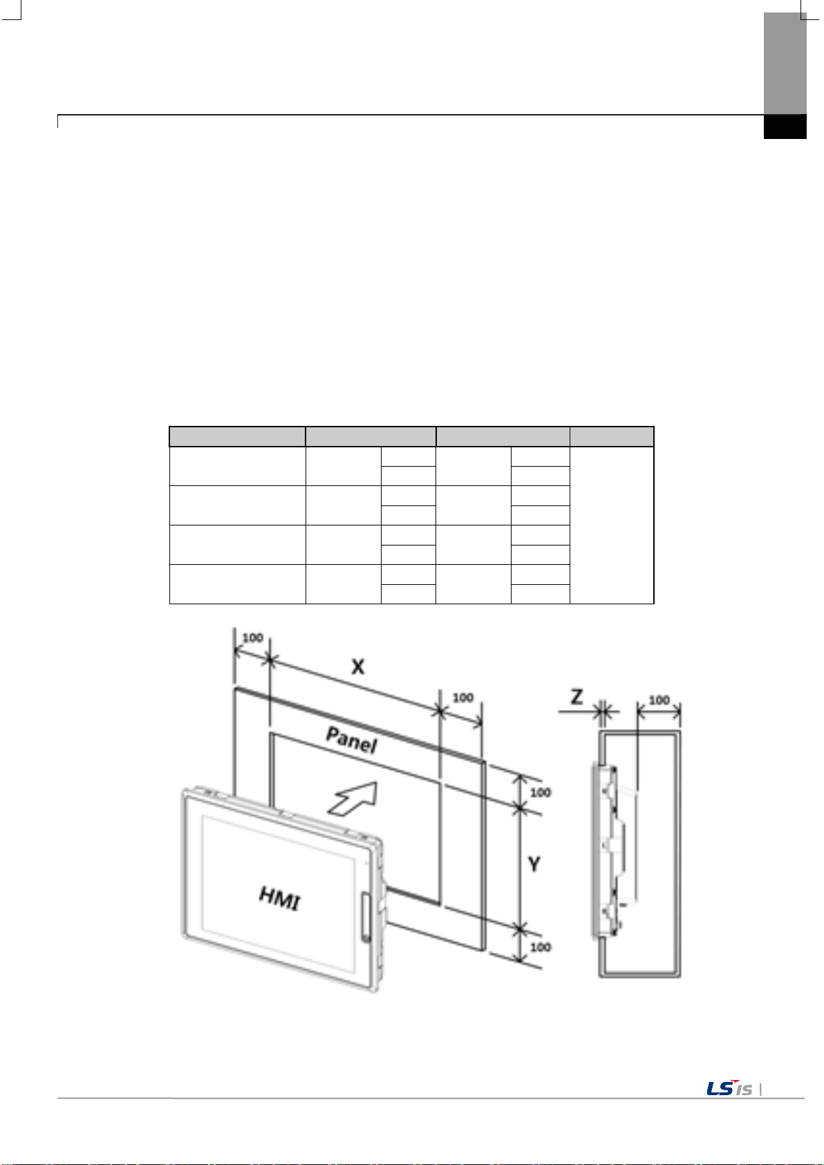
division
X (Horizontal)
Y (Vertical)
Z (Thickness)
+1
+1
-0
-0
+1
+1
-0
-0
+1
+1
-0
-0
+1
+1
-0
-0
Unit: [mm]
Chapter 4. Installation and Wiring
4.1.2 Notice in handling
This section describes the precautions for han dling the XGT Pan el from opening to in stallation.
• Do not drop or subject it to strong impacts.
• Do not open the product case or take any action. In such cases, we are not responsible for the product.
• When wiring, be careful not to let foreign substances such as wiring residue into the XGT Panel.
4.1.3 Precautions for panel in stallation
Describes how to install th e XGT Panel on the panel and notes.
(1) Pan el cut
• Before installing the XGT Panel on the panel, it must be manufactured on the panel as shown in the table below.
iXP2-08XX 228.5
iXP2-10XX 259.0
iXP2-12XX 301.5
iXP2-15XX 383.5
158.5
201.0
1.6 to 9.5
227.5
282.5

4-4
Note
(1) In order to be less affected by el ectromagnetic waves (radia tion noise) or heat ge nerated by other con trol devices,
reference tolerance (0 ~ + 1mm) when making the panel, the gap
The contact area may be reduced, and the waterproof and dustproof effect may be
f and dustproof. The XGT Panel basically has a
(5) If the surface of t he panel on w hich the XGT Panel i s mount ed is uneven, there i s a gap be tween the XG T Panel and th e
It is absolutely
are should be taken becau se it can be significan tly w eakened, and i f a
gasket needs to be repla ced, contact your neare st dealer or serv ice. Pl ease contact the center.
Division
Angle (le ft and ri ght)
Upper
Lower
iXP2-08XX
80 deg.
80 deg.
60 deg.
iXP2-10XX
75 deg.
75 deg.
75 deg.
iXP2-12XX
80 deg.
80 deg.
80 deg.
iXP2-15XX
80 deg.
80 deg.
80 deg.
100
100
100
100
Chapter 4. Installation and Wiring
(2) Panel in stallation
• When mounting the XGT Panel on the panel, please install 100mm or more in each direction.
Unit: [mm]
100
Required.
(2) Install it conside ring the wiring of pow er and communication cables.
(3) When the panel cut dimensions are outside the
between the gasket and the panel.
weakened.
(4) When mounting the product on the panel, use gasket for waterproo
waterproof and dustproof gasket is equipped.
panel, or dust may penetrate. Particularly, depending on the material (steel , aluminum, a crylic, etc.) of the panel, This may
require installation environment review. Also check that the gasket and panel are in close contact.
necessary.
(6) If the condition of the gasket is contaminated or dama g e d du e to deterioration at th e t ime of insta l la t ion or after a c er tain
period of use, the w aterproof and du stproo f effe ct c
•
When installing the product on the panel, use gasket for waterproof and dus tproof. The XGT Panel i s basically equipped w ith
a waterproof and dustproof gasket.
(3) Installation location
• Please consider screen display and touch use for XGT Panel installation.
• If you exceed the display angle bel ow, the screen may not be clearly visible. It is recommended to install the prod uct considering
the angle of view.

4-5
Fixed Bracket
Panel
Note
(1) During installation, XGT Panel should be closely contacted to the panel not to have any gap. In the
cm. Depending on the material type of the panel, the torque value can be
different. The standard screw torque for each bolt size is followed. If it is fixed with the power more than
to the deformation of XGT Panel.
Remark
, contact the
agency or a sales office close by.
(4) Fixing
• Fix the XGT Panel using the brackets on the panels as shown below.
(The bracket is included i n the product.)
Chapter 4. Installation and Wiring
environment requiring water-proof/dust-proof effect, install and fix a bracket on a slope.
(2) The bracket should be fixed symmetrically(Up-Down, Left-Right). In case when it is not fixed
symmetrically, there could be a gap between the panel and XGT Panel.
(3) When fixing the bracket, it should be installed perpendicularly to the panel, and the required bracket
screw torque is 6.7kgf ㆍ
the requir ed s cr ew t orq ue, the to uch m a lfu nct ion or we ak enin g of water -proof/dust-proof ca n happe n due
(5) Removal of protective film
• Be sure to remove the film attached to the panel to protect the front sheet when it is shipped from the factory .
(1) Remove the protection film attached to the front of this machine. Due to the deformation of the
protection film, the touch malfunction or wrong input can occur. It is recommended to use a special
protection sheet to protect the front sheet. In case of purchasing the protection sheet

4-6
power
Product Name
iXP2-1500D
iXP2-0800A
iXP2-1500A
► Connecting AC power to a device that uses DC power may cause product damage or fire.
Caution
Chapter 4. Installation and Wiring
4.2 Wiring
Describes the wiring matte rs when installing the XGT Panel.
4.2.1 Power Wiring
XGT Panel is divided into DC (DC) and A C (AC) products.
DC 24V
iXP2-0800D
iXP2-1000D
iXP2-1200D
AC100-240V
Be careful of connection.
► 'XXD' is a product using DC 24V and 'XXA' is a product using AC100-240.
Be sure to check the polarity of the back of the product before use.
iXP2-1000A
iXP2-1200A

4-7
ground
Note
aid safe terminations.
Power
Supply
L N PE
+ -
PE
Note
(1) When the power flu ctuation is larger than t he specified value range, use a constant vol tage transfor mer.
(3) Momentary power failu re for stable data ba ckup when power on / o ff. Please use.
[AC connection]
[DC connection]
Use the following specifications for the power cable.
Type Cable specification (Unit: ㎟) Wire Type Thermal Resistance Screw Torque
Chapter 4. Installation and Wiring
Power and protection
(1) For installations where there is voltage drop, it is recommended to use stranded wire with a cross
sectional area greater than 2 ㎟.
(2) It is recommended that cable connections are twisted and secure. Short cable runs are also
recommended between the poin t o f supp ly and the XGT panel.
(3) For safety reasons it is recommended that you use color coded outer sheaths on the conductors to
Power connection is as shown below.
1.5(AWG16) ~ 2.5(AWG12) Copper 60℃ 0.51N•m
(2) When there is a lot o f noise in the pow er supply, use an in sulation transformer.

4-8
Main
Power
Noise
Filter
HMI
power
PE
Others
Note
Note
E2
E1
Surge absorber for preventing lightning
Chapter 4. Installation and Wiring
For XGT Panel power supply , I / O devices and pow er devices, separa te the power supply system as shown below.
Do not bring the power line of the XGT Panel close to the main circuit (high voltage , high current) line o r I / O signal
line. Possible 100mm Install at an interval of more than two.
Use the surge absorber as shown in the figure below to prevent su rge such as lightning.
XGT Panel
(1) Separate grounding (E2 ) of the XGT Panel of g round surge absorber (E1).
(2) Select the surge ab sorber so that the surge absorber does not e xceed the maximu m allowable voltage even w hen
the power supply voltage rises to a maximu m please give it to me.

4-9
L N PE
Ferrite Core
(CU1130B, E-TECH)
(CU1330G, E-TECH)
(ZCAT3035-1330, TDK)
Note
Type-3 ground
Type-3 ground
Chapter 4. Installation and Wiring
When there is concern about n oise penetration , use an insulation shi eld transformer or a noise filter.
Be sure to twist the wi ring of the input pow er supply as short as possible and do not let the wiring of the shielding tran sformer or
noise filter pass throug h the duct.
When using a magnetic contactor (MC) for AC / DC, it is recommended to use Ferrite Core at the power input terminal.
EX) Apply a ferrite core to the po wer terminal as show n in the figure.
4.2.2 Ground Wiring
(1) This XG T Panel has enough noise countermeasures, so it can be used without g rounding except when there is a lot of noi se.
However, when grounding, plea se refer to the foll owing.
(2) Grounding should be done by dedicated grounding as much as possible.
Grounding works are clas sified as class 3 gro unding (grounding re sistance 100 Ω Or less).
(3) When dedicated grounding i s not possible, u se common ground as show n in Fig.
(4) Ground wire is 2 mm
wire.
XGT Panel
A) Exclusive ground: Best B) Common ground : Good C) Common ground: Bad
2
Other
or more. If possible, place the groundi ng point near the XGT Panel to shorten the length of the g round
XGT Panel
Other
XGT Panel
Other
If the grounding condition is bad or connected as in (C), the XGT Panel may malfunction or communication failure
may occur. Be sure to check grounding.

5-1
WinCE O/S V1.0 XP-Runtime V2.10 B[010]
Configuration menu of
Backlight Setting
Touch Setting
DateTime Setting
Environment Setting
Ethernet Setting
Buzzer Setting
Sound Setting
XP-Remote Setting
Goto MainMenu
Diagnostics function of
Screen
Touch
Backup Memory/
Flash Memory
USB Memory
Serial
SD Card
Chapter 5 XGT Panel Menu Explanation
Chapter 5 XGT Panel Menu Explanation
This chapter describes how to set the environ ment such as XGT Panel ti me setting, Ether net connection setting, backlight setting.
If you press the [Setti ngs] button on the XGT Panel main screen, you can set the environment of XGT Panel.
[XGT Panel Basic]
After booting the XGT Panel after turning on the power, the XP-Runtime main screen is displayed. Functions of each menu are as
follows.
Menu Meaning Details Note
Settings
Diagnostics
XGT Panel
XGT Panel
Refer to 5.1 Settings
Refer to 5.2 Diagnostics

Goto MainMenu
Settings
SHOW INFO
Program Monitor
OK
N:1 Settings
XGT Panel Update
Refer to
5.4 Update XGT Panel
Project Download
Project Upload
XGT Panel Update
Select USB
Cancel
Chapter 5 XGT Panel Menu Explanation
구분 의미 세부 항목 비고
PLC setting menu
PLC Information
Update XGT Panel For updating XGT Panel
Storage Function
connected with
XGT Paenl
It is for using
the storage devices
used in XGT Panel
Refer to
5.3 PLC Information
Refer to
5.5 Storage Function
5-2

5-3
WinCE O/S V1.0 XP-Runtime V2.10 B[010]
5.1 Settings
Chapter 5 XGT Panel Menu Explanation
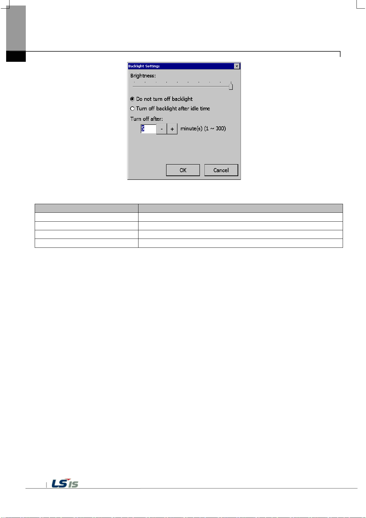
5.1.1 Backlight Setting
Press the [Backlight Settings] button on the [Sy stem Configuration] screen to go to the setup screen as follows.
[XGT Panel Setting]
Menu
Explanation
Brightness
Backlight Brightness can be adjusted.
Do not turn off backlight
Backlight power is always on.
Chapter 5 XGT Panel Menu Explanation
[Backlight setting]
Turn off bac klight after idle time If you do not touch for a certain period of t ime, the backlight auto matically turns off.
Turn off after The backlight turns off after the set time (in minutes).
[Explanation of the dialog box]
5-4

5-5
Note
Chapter 5 XGT Panel Menu Explanation
5.1.2 Touch Setting
You can adjust the sensitiv ity of the touch a ccording to the ty pe of gloves according to the work environ ment during touch ope ration. If
you press [Touch Setting] on the System Configur ation screen as shown below, the setting w indow will be activat ed and you can set
the sensitivity according t o the type of glove . You can set the sensitivity of the to uch by user settin g.
[XGT Panel Setting]
[Touch setting]
(1) By default, XGT Panel h as touch setting. I f the touch position error is large, Please contact us for action.
(2) If touch glass breakage occurs, it may cause touch operation proble m.

2017
Today: 4/23/2017
Note
Chapter 5 XGT Panel Menu Explanation
5.1.3 DateTime Setting
You can set the date and time of XGT Panel by pressing [DateTime Setting] button on [System Configuration] screen as follows.
[XGT Panel Setting]
[Date / Time Setting]
5-6
Date / time view and setting are also available in the device information view of the communication setting dialog of XP-Builder.
For more information,See the XP-Builder User's Guide Chapter 4.4.

5-7
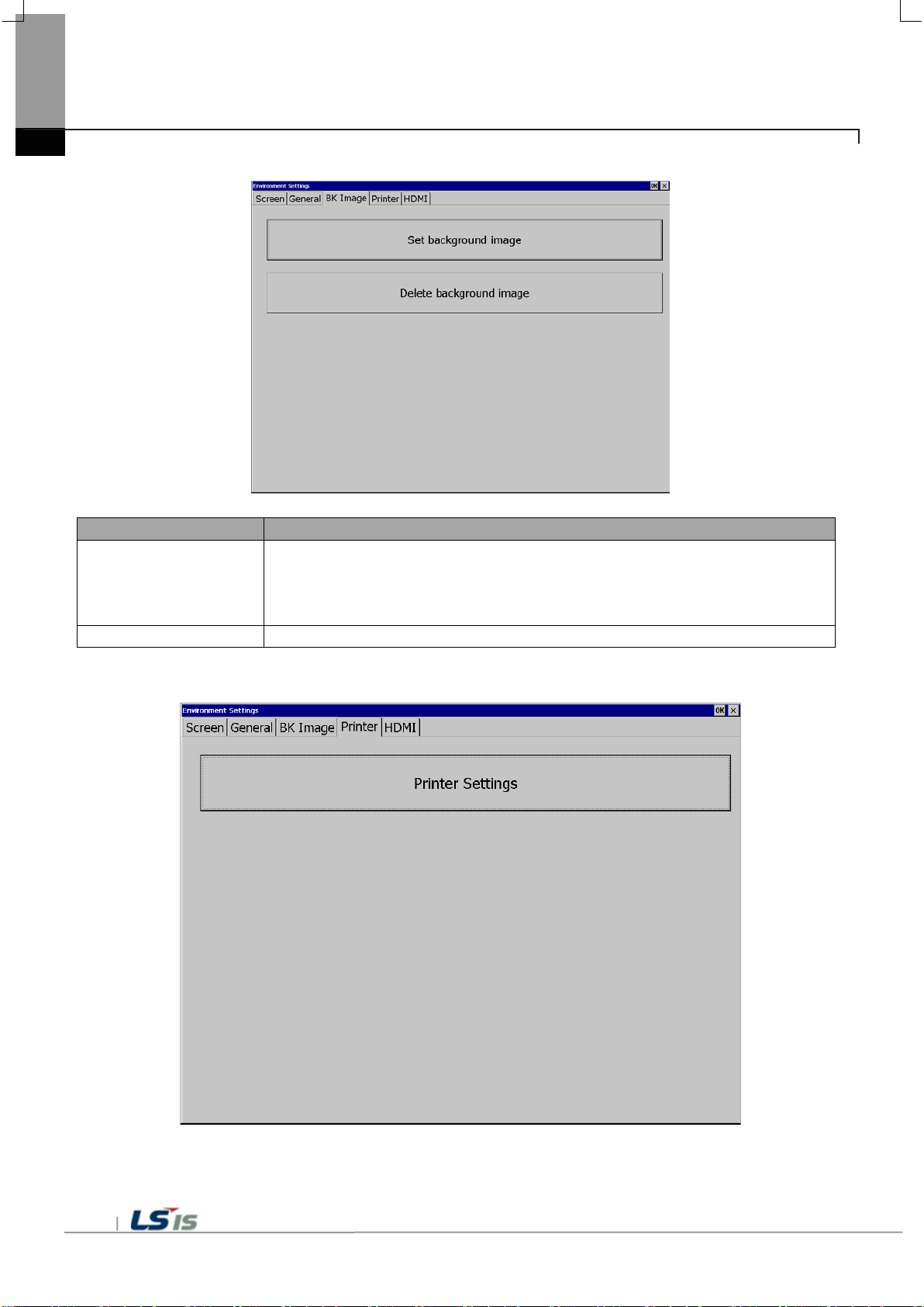
5.1.4 Environment Setting
If you press the [Envir onment Setting] button on the [System Configuration] screen to go to the setup screen as follow s.
Chapter 5 XGT Panel Menu Explanation
[XGT Panel Setting]

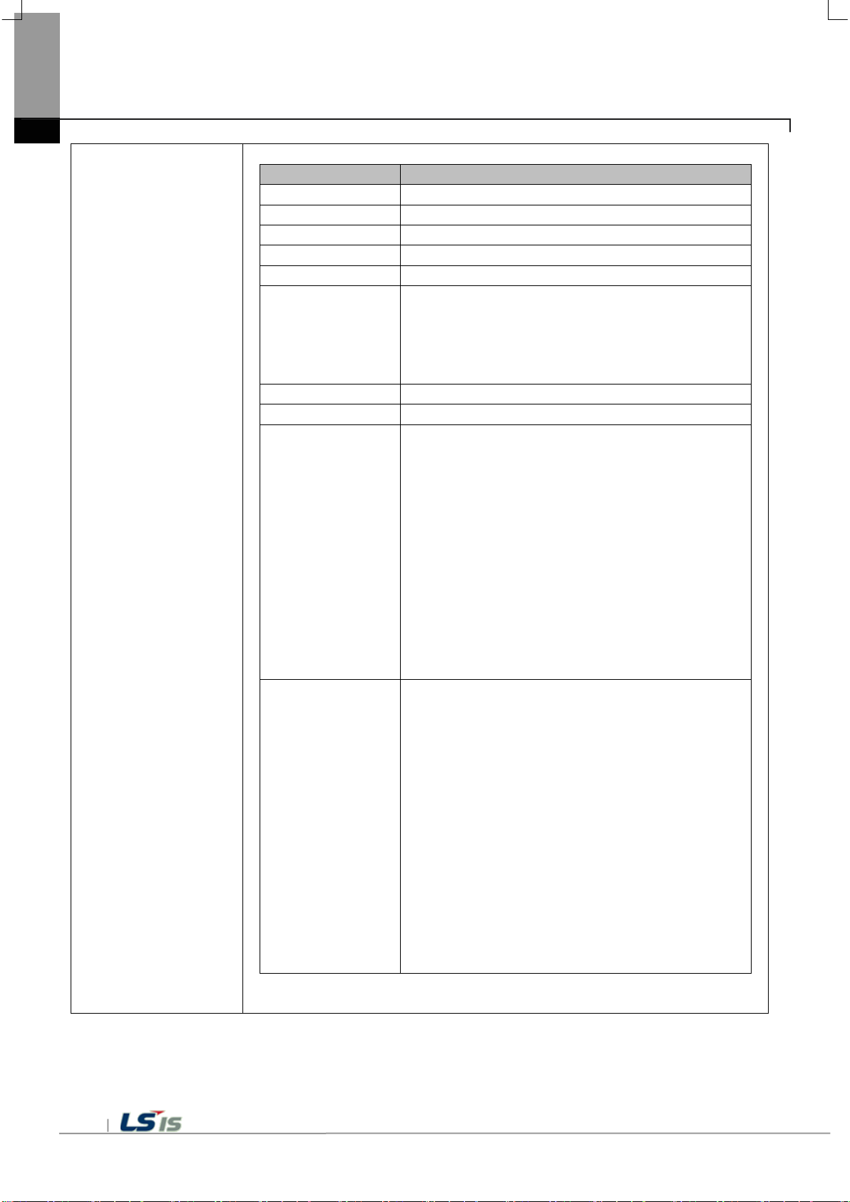
Menu
Explanation
Goto screen
After rebooting XGT Panel or downloading edit data,
Button to move to the screen.
Quick start
When I start the screen, I do not cache the image in advance,
It may take a few seconds. The next screen transition is fast.
Show progress
When you start monitoring by selecting [Start] menu on the XGT Panel main screen,
Is displayed. This option can be applied when using the default screen image.
Show always ti tle bar
of popup window
Displays the title bar in a pop-up window. Select the title bar of the pop-up window and
Y ou can move.
Do not show menu bar
In order to exit to the standby screen during screen monitoring,
Y ou need to configure and use a special switch to exit the screen.
Display (right-> left)
Set startup screen
The screen corresponding to the number entered at the start of monitoring is displayed.
Chapter 5 XGT Panel Menu Explanation
(1) Screen
after boot up
on the bottom
Y ou will switch . If you di sable thi s setting ,
It does not appear. However, if you select this option, the initial screen may appear
somewhat late.
There is. In particular, if the screen contains animation objects,
It buffers the used image and shows the progress of the operation. (fast
Do not show progress if you make a start setting). At this time,
If you check the [Show Lower] check box, this progress will be simplified and displayed at
the bottom of the screen.
The window (menu bar) does not appear. If this is the case,
Enable Arabi c text
5-8
Enables the right-to-l eft language.

5-9
Menu
Explanation
Hide mouse cursor
Mouse cursor does not appear after scrolling.
Buzzer On / Off
Y ou can set whether buzzer is used or not.
Buzzer test
Y ou can test the buzzer.
The operation to delete may be repeated, and the screen switching operation may be
results in less memory usage and less load to load and delete images into memory.
Uncheck, power on again an d try again .
Clear SRAM memory
Delete all fil es you'v e downloa ded on your dev ice. How ever , c onnectin g to the devi ce
A device reboot is required to delete files.
(2) General
Chapter 5 XGT Panel Menu Explanation
Low Memory Mode XGT Panel star ts monitori ng the images used on th e screen to speed up the screen
operation.
It will be loaded into memory before use. By the way ,
If a positive image is used, due to memory space constraints, all
The image will not load. In this case, if the screen is not yet loaded
Images are loaded, and there is not enough space, so unused images are retrieved from
memory
slowed down. In this situation
Low Memory Mode "is rec om mended. In Low Memory Mode , you do not load t he image
before monitoring, but use only the original source of the image used in the project, which
Reset USB power
after boot up
When XGT Panel starts, it turns off USB power On to initialize the connected device.
The initial setting is On, and if t he USB reco gnition s peed is sl ow or not wel l recogniz ed
And data files
If a password is set, you must enter the password before you can delete it. The password
is the device connec tion password th at you enter whe n download ing a project, This can
be set in XP-Builder on the Device Information View tab of the Communication dialog box.
The files to be deleted include user project data, we b ser v er, VNC startup modul e, op ti on
card Driver, RAPIEnet communication setting data, XP-Manager sett ing data etc. from
user PC All downloaded data is included. Set using the configuration menu of the
machine. The contents are kept uninitialized. If the menu language is not English,
Menu
Explanation
Set background image
If you select an image, the standby screen and desktop are selected after the XGT Panel
It can not be used unless it is a 24bit BMP image.
Delete background image
Deletes the set desktop.
Chapter 5 XGT Panel Menu Explanation
(3) BK Image
(4) Printer
is powered on.
If [Use boot image] option is selected, images with resolutions other than XGT Panel,
5-10

5-11
Menu
Explanation
Chapter 5 XGT Panel Menu Explanation
Printer Settings Displays additional printer print settings dialogs. If there is no printer information
Y ou should download from XP-Builder with the following message.
From XP-Runtime, go to Start menu and prepare for downloading.
After using the printer, you can use the menu.
<No printer driver and information Dow nload Requi red>
<Printer Driver and Information Available>
Printer Settings
Menu
Explanation
Port
Connection method: Displays the connection method.
Printer type
Printer type: Displays the printer type.
Print direction
Orientation: Set whether it is horizontal or vertical.
Print color
Print color: Set whether it is color or black and white.
High quality print
Print quality: Set whether to print advanced.
More ...
View add itional properties: Displays additional properties.
Go to the dialog box.
OK
Save the settings.
Cancel
Cancels the setting.
4. Paper Empty: Out of paper
T est Page
T est printing: T o test the printout status
Chapter 5 XGT Panel Menu Explanation
Printer Properties
If you have made any changes, check whether you want to
save it,
Printer Check D ia gn os e connectivity: Diagnoses the connec t io n sta t us of
the printer. this
The functions of the printer (LK-P30, LK-P 41, LK -P43)
Support. Press the button to the right of the current status
Displays a message. If the printer is off
Y ou can turn it on, connect the cable again,
There is.
* Message Ty pe *
One. OK: normal
2. No Printer: Not compatible with printer
3. Cover Open: Paper cover opened
Function. It prints the following information and briefly
Outputs the printing status.
<Example of test page>
***********************************
T est page
***********************************
DateTime: 2014-02-0 4 10:00:00
XP-Runtime version: 1320
Printer driver version: 1.00
Printer name: PCL3 LaserJet
Port: USB
***********************************
5-12

5-13
Menu
Explanation
Not used
HDMI function is disabled.
Clone mode
The same screen is displayed on the monitor connected by HDMI.
(T o be implemented)
(5) HDMI
Chapter 5 XGT Panel Menu Explanation
Extended mode
Expands the screen to a monitor connected via HDMI.
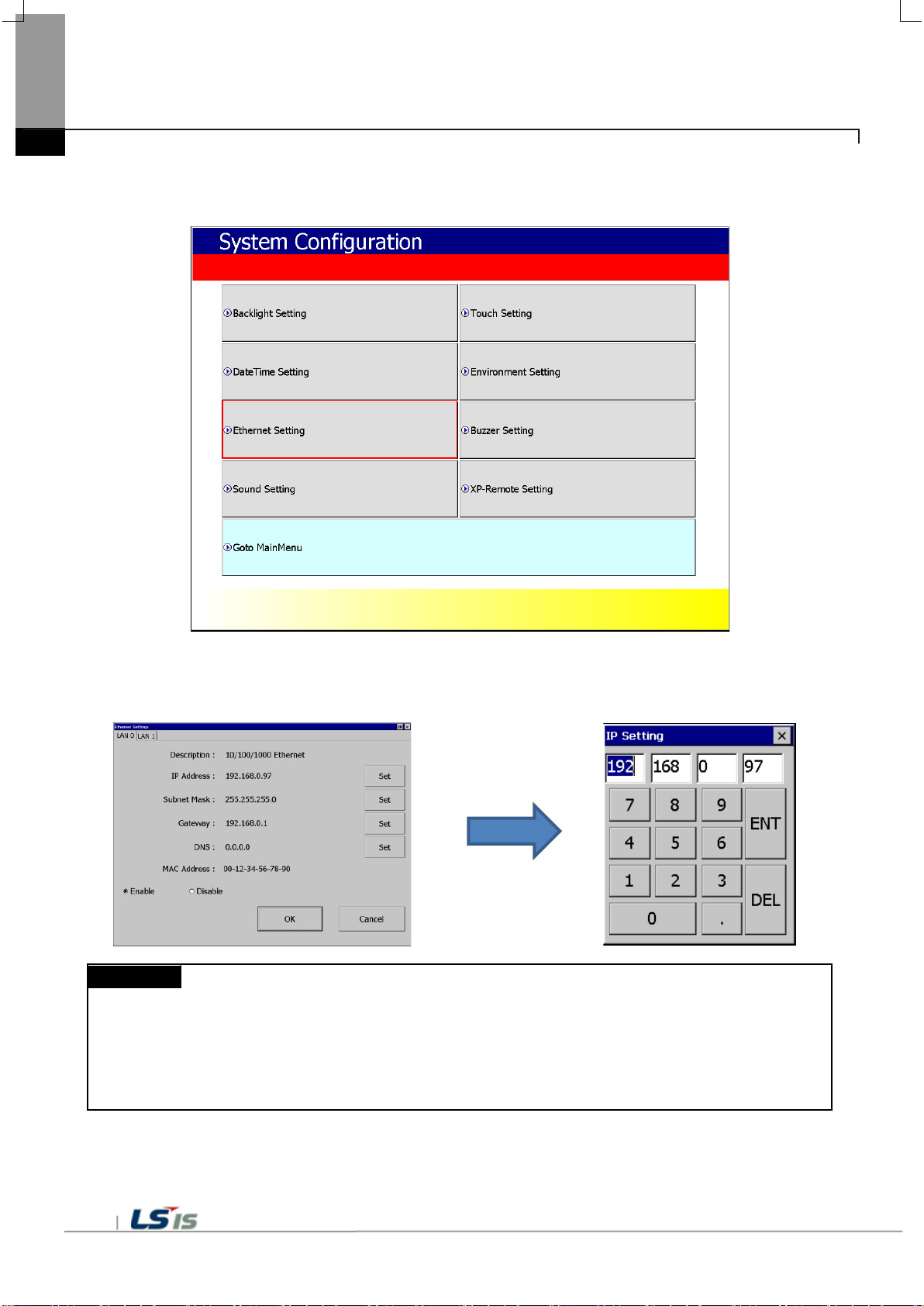
Note
For 1: 1 connection with PC, i t is recommended to set as follows.
- Gateway: 192.168.0.1
- Gateway: 192.168.0.1
Chapter 5 XGT Panel Menu Explanation
5.1.5 Ethernet Setting
If you press the [Etherne t Setting] button on the [System Config uration] screen as below , you can set the IP to use Ethernet.
You can change the IP by pressing the [Set] button for each item o f IP address, Subnet Ma sk and Gateway.
If you click [OK] button, changed IP info rmation will be saved. Two Ethernet port s [LAN 0] and [LAN 1] can be set respectivel y.
1) XGT Panel setting
- IP address: 192.168.0.10
- Subnet Mask: 255.255.255.0
2) PC setting
- IP address: 192.168.0.11
- Subnet Mask: 255.255.255.0
If you press the [Disable ] button and reboot, the device will n ot use Ethernet. I f this is the ca se,
You can get the effect. To use Ethernet again, p ress [Enable] but ton and reboot.
5-14
5-15
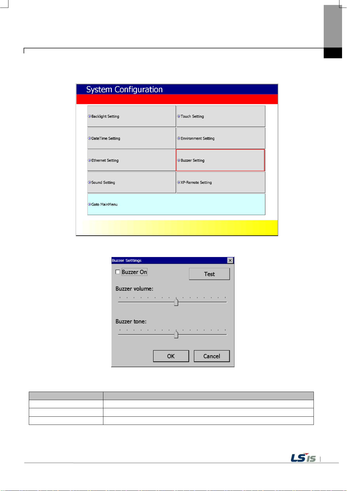
Menu
Explanation
Buzzer On
Y ou can turn on or off the buzzer sound generated when the selection is made.
Buzzer volume
Y ou can adjust the volume of the buzzer.
Buzzer tone
Y ou can adjust the height of the buzzer.
5.1.6 Buzzer Setting
You can adjust the volu me and tone of Buzz er of XGT Panel.
Chapter 5 XGT Panel Menu Explanation
[Explanation of the dialog box]
[XGT Panel Setting]
[Buzzer setting]
Chapter 5 XGT Panel Menu Explanation
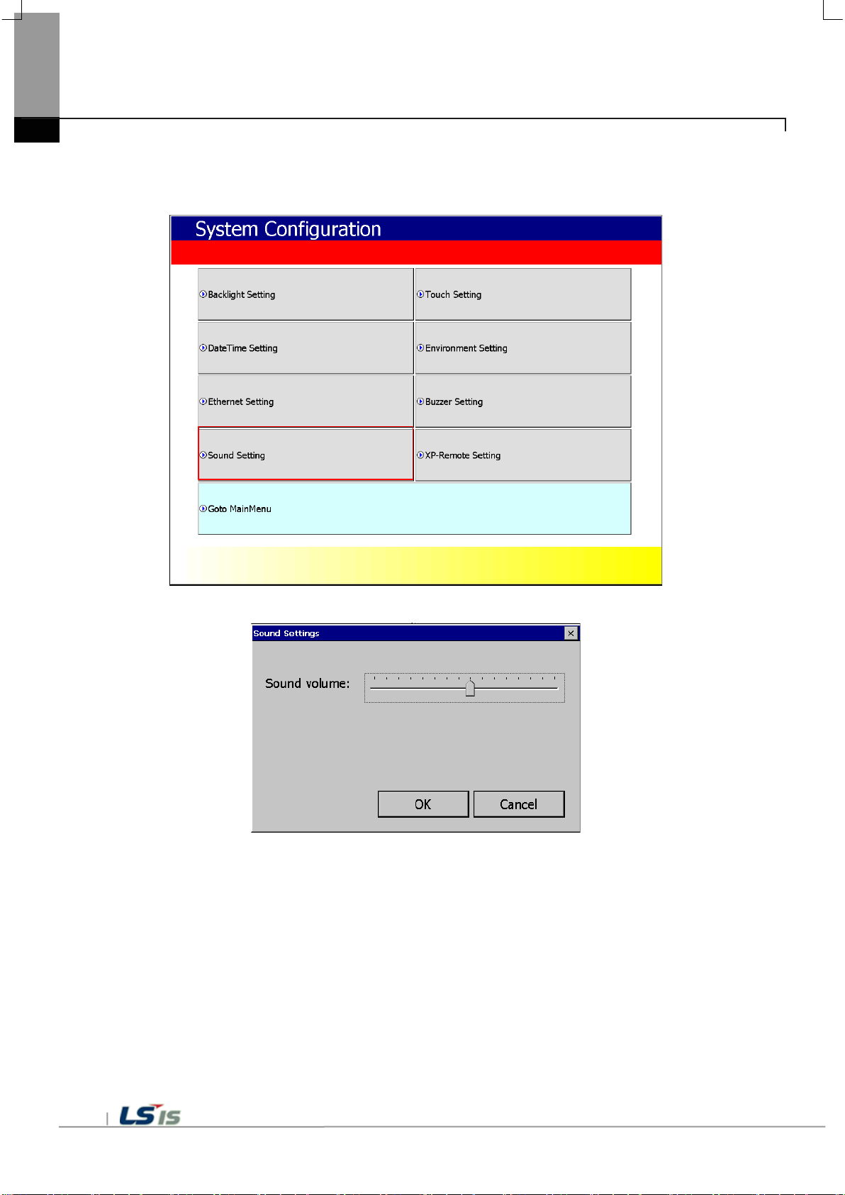
5.1.7 Sound Setting
You can adjust the volu me of XGT Panel.
[XGT Panel Setting]
[Sound setting]
5-16

5-17
Menu
Explanation
Allow XP-Remote to connect
Allow connection of remote XP-Remote.
Max. of XP-Remote
Specify the maximum number of XP-Remote that can be connected to XGT Panel.
(10 seconds ~ 300 seconds)
Enable control by XP-Remote
after Monitor Start
After XGT Panel starts to monitor, operation permission status is automatically set.
Note
Chapter 5 XGT Panel Menu Explanation
5.1.8 XP-Remote Setting
Y ou can change the settings for XP-Remote that can remotely control the XGT Panel.
[XGT Panel Setting]
[XP-Remote setting]
[Explanation of the dialog box]
Timeout value If there is no communicat ion request f rom XP-Remote within th e designate d time,
communication is stopped,
If XP-Remote has operation authority , it recovers operation authority.
For details of XP-Remote, refer to the XP-Remote User's Ma nual.

WinCE O/S V1.0 XP-Runtime V2.10 B[010]
Chapter 5 XGT Panel Menu Explanation
5.2 Diagnostics
This chapter explains the functions that can be used to diagnose co mmunication terminal, screen and touch function of XGT Panel.
If you click the [Diagno sis] button on the main screen of XGT Panel, a menu for diagnosi ng each function of XGT Panel is displayed.
[XGT Panel Basic]
[XGT Panel Diagnostics]
5-18

5-19
order
Chapter 5 XGT Panel Menu Explanation
5.2.1 Screen Diagnostic
When you press the [Screen] button, the screens with different colors are displayed in succession with the buzzer sound. After
all the scre ens for diag nosis are d isplayed, the gr aph will app ear and the [Close] butt on will appear in the upp er left corn er.
When this [Close] button is pressed, Returns to the Diagnostics screen.
Screen
Red Green Blue Black White Graph
[XGT Panel Diagnostics]
[Screen Diagnostic]

Chapter 5 XGT Panel Menu Explanation
5.2.2 Touch Diagnostic
When you press the [Touch ] button, the diagnos tic screen appears.
If you touch the screen , you can see that it is displayed like the picture bel ow.
Press the [OK] button to exit the screen.
[XGT Panel Diagnostics]
[Touch Diagnostic]
5-20

5-21
Note
If the rear setting switch 1 is set to B, set it to ON. B is a mode without backup battery .
5.2.3 Backup Memory Diagnostic
If you press the [Bac kup Memory] button, y ou can see the diagn ostic results in the confirmation wi ndow.
Chapter 5 XGT Panel Menu Explanation
[XGT Panel Diagnostics]
[Backup Memory Diagnostic]
(1) If 'NVRAM Data Acces s ~~ Fail' occur s, take A/S action.
(2) If 'BATTERY STATUS ~~ BAD' occurs, you have to replace the battery through A/S.

Note
2. Spa ce allocation of Flash Disk may depending on O/S version.
Chapter 5 XGT Panel Menu Explanation
5.2.4 Flash Memory Diagnostic
When you press the [Flash Memory] button, the dia gnostic results app ear in the confirmati on window.
[XGT Panel Diagnostics]
[Flash Memory Diagnostic]
1. I f "Read Disk Infor mation Error!" Occur s, please contact us.
5-22

5-23
Note
If USB memory is installe d and 'Read Disk In formation Error!' Occurs, remove it, in sert it again and te st
do it. If the error mes sage occurs repeatedly , contact Customer Service.
Chapter 5 XGT Panel Menu Explanation
5.2.5 USB Memory Diagnostic
When you press the [USB Me mory] button, the dia gnostic result appear s in the confirmation window.
[XGT Panel Diagnostic]
[USB Memory Diagnostic]

Chapter 5 XGT Panel Menu Explanation
5.2.6 Serial Diagnostic
Diagnostic function for serial communication port such as RS-232C, RS-422. Press the [Serial ] button to diagnose the serial
ports installed on the XGT Panel. (However, for diagnosis, loop bac k terminal must be connected to each port.)
[XGT Panel Diagnostic]
[Serial port selection screen]
[Serial Diagnostic]
5-24

5-25
Pin
er
name
function
One
TX +
Data transmission
2
TX-
Data transmission
3
RX +
Receive data
4
RX-
Receive data
5
SG
Signal Groun d
6
PE
PE
Chapter 5 XGT Panel Menu Explanation
Please make RS-232C port terminal as below. (Connect pins 2 and 3.)
Connect the RS-422/ 485 port t erminal s as shown be low .
(In case of RS-485 c ommunic ation, con nect pin 1, pin 3, pin 2 and pin 4)
nu
mb

Note
If the error message occu rs repeatedly , take A / S action.
Chapter 5 XGT Panel Menu Explanation
5.2.7 SD Card Diagnostic
Displays information of SD card memory i nserted i n XGT Pa nel . Press the [SD Card] button to diagnose the SD memory mounted
on the XGT Panel.
[XGT Panel Diagnostic]
[SD Card Diagnostic]
If 'Read Disk Information Error!' Occurs w hen an SD card is inst alled, remove it, inse rt it again, and tes t it.
5-26

5-27
WinCE O/S V1.0 XP-Runtime V2.10 B[010]
Note
Chapter 5 XGT Panel Menu Explanation
5.3 PLC Information
The PLC informat ion view function is to view the conn ected XGT Panel information an d CPU information and his tory of the
target PLC.
[XGT Panel Basic Screen]
PLC connection status can be viewed only when project data is t ransferred to XGT Panel.

Note
Chapter 5 XGT Panel Menu Explanation
5.3.1 PLC Communication Setting
[Settings] is a function to change communi cation parameters of PLC communicating with X GT Panel, and you can change
PLC communication setting items by clicking [Setti ngs] button
[PLC information]
[PLC Communication Setting]
- PLC communication setting sc reen may be different for each driver.
- Refer to individual PLC manual for PLC communi cation setting change contents.
5-28

5-29
Item
Explanation
Connection No.
Displays the communication connection number. Available from 0 to 15.
Vendor
Displays the manufacturer of the communication target device.
T arget device
Displays the communication target device.
Connection type
Displays the conne ction method. (RS-232, RS-422, TCP/IP , ect.)
Timeout value
Displays the set timeout time.
Send wait value
Displays the transfer waiting time.
Displays the number of retransmissions when a timeout occurs during
communication.
Chapter 5 XGT Panel Menu Explanation
5.3.2 Connection Information
You can check the connection number, PLC manufacturer, ta rget PLC type, connection method, IP address, and timeout ti me set up
for connection with PLC i n XP-Builder.
[PLC information]
[Explanation of the dialog box]
Retry value

Note
- XGK / XGB / XGI / XGR CPU, FEnet, Cnet
Note
The PLC types that can di splay the error histo ry are as follows.
- XGK / XGB / XGI / XGR CPU, FEnet, Cnet
Chapter 5 XGT Panel Menu Explanation
5.3.3 PLC Information
You can check the CPU ty pe, operation mode, statu s, version and scan time of our own PLC model and provide in formation only
when connected with PLC.
PLC types that can view PLC information are a s follows.
- MASTER-K CPU, FEnet, Cnet
- GLOFA-GM CPU, FEnet, Cnet
5.3.4 History of PLC error
You can check the PLC e rror history of y our own PLC model.
- The MASTER-K CPU has no error history.
- GLOFA-GM CPU, FEnet, Cnet
5-30

5-31
Note
- XGK / XGB / XGI / XGR CPU, FEnet, Cnet
Note
Chapter 5 XGT Panel Menu Explanation
5.3.5 PLC Operation Mode Conversion History
You can check the PLC run / stop opera tion mode history of your PLC model.
The following PLC types a re available to view the PLC operation mode switching history .
- MASTER-K CPU does not h ave operation mode switching history .
- GLOFA-GM CPU, FEnet, Cnet
5.3.6 History of power off of PLC
You can check the PLC power shutdown history of your own PLC ty pe.
PLC type that can view th e power off history is as follows.
- MASTER-K CPU has no pow er off history .
- GLOFA-GM CPU, FEnet, Cnet
- XGK / XGB / XGI / XGR CPU, FEnet, Cnet

Note
- XGK / XGB / XGI / XGR CPU, FEnet, Cnet
Chapter 5 XGT Panel Menu Explanation
5.3.7 PLC System History Information
PLC system history can be checked.
The PLC types that can view the system histo ry are as follows.
- The MASTER-K CPU has no system history.
- Only available with the GLOFA-GM CPU (GM4C). Other CPUs have no system history.
5-32

5-33
Menu
Explanation
Use N: 1 Communication
N: 1 Specifies whether to perform communication.
N: 1 station number
Enter the station number of N: 1 communication.
Number of XGT Panel
N: 1 Enter the number of XGT panels on communication.
Master Holding Time
Enter the master execution time of N: 1 communication.
Note
Chapter 5 XGT Panel Menu Explanation
5.3.8 N: 1 Setting
XGT Panel supports N: 1 service which enables communication between sev eral XGT Panels and one PLC. You can set de tails
using the [N: 1 Setting s] menu.
[Explanation of the dialog box]
[PLC information]
[N: 1 setting]
For detailed setting and understanding of N: 1 communication , refer to XP-Builder's N: 1 communication manual.

Note
You must specify the use of the program monitor in the project properties of XP-Builder.
Chapter 5 XGT Panel Menu Explanation
5.3.9 Program Monitor
XGT Panel can monitor ladde r of PLC XGK of LS Indu strial Systems.
[PLC information view s creen]
- Program monitor module s must be installed via XP-Manager.
- LSIS: XGK / XGB CPU, Cnet, and Enet driver.
-
5-34

5-35
WinCE O/S V1.0 XP-Runtime V2.10 B[010]
Note
1. Do not disconnect the communication cable or turn off the device while updating the XGT Panel.
screen.
Chapter 5 XGT Panel Menu Explanation
5.4 XGT Panel Update
The functio ns d esc r ib ed in th is chapter are for up da ti ng t he X G T P an el s of t war e. B y d ef au lt , X GT Pa ne l is a ls o op timized
when downloading project file from XP-Builder. Use this function only if you need to update only the XGT Panel in particular.
The software of the XGT Panel will need to be updated with the new version as new functions and enhancements are
added. Refer to the following procedure.
[Method]
1. Connect XGT Panel and PC.
2. Run the XP-Builder.
3-1. Click [Communication] - [XGT Panel Update].
3-2. Click Connection Setup to select the type of XGT Panel and PC connected.
3-3. Clic k Browse an d select the XP-Runtime file.
4. Select [XGT Panel U pdate] on the XGT Panel menu screen.
5. Click [Update] of the XGT Panel Update(No3-1).
When normal update is completed, return to XP Runtime menu screen.
XGT Panel may not update properly and may malfunction
2. Click Update XGT Panel menu and then click MENU on XP-Runtime screen to return to XP-Runtime menu

WinCE O/S V1.0 XP-Runtime V2.10 B[010]
Menu
Description
Chapter 5 XGT Panel Menu Explanation
5.5 Storage Function
5.5.1 Overview
Download the project edited by the user in XP-Builder from PC or upload the project backed up in the device to PC
Uploading and updating the device are usually done by connecting USB cable or Ethernet cable to XGT Panel series.
Y ou can do it through. In situations where this connection is not possible, you can use the storage device to proceed.
The function description for [Storage Function] is as follows.
1. If you touch [Storage Function] on the menu, the following dialog box is displayed.
2. The contents of each menu are as follows.
Project Download To dow nload a project from an external storage device to the XGT Panel
Project Upload To transfer project data backed up to an external storage device from XGT Panel
XGTPanel Update T o update the XGT Panel Software from an external storage device
5-36

5-37
Chapter 5 XGT Panel Menu Explanation
5.5.2 Downloading a project using a storage device
1. When you touch [Download Project] in the storage function menu, the following dialog box is displayed.
2. Project storage path of USB memory, SD card is displayed as below.
- \ USB Storage \ XP_Project \
- \ SD Storage \ XP_Project \
If you want to download a project using a storage device, it must be stored in the directory in the above path.
3. Select one of the directory listings.
4. T ouch the [OK] button to start the download.

Chapter 5 XGT Panel Menu Explanation
5.5.3 Uploading a project using a storage device
1. If you touch [Upload Project] in the storage function menu, the following dialog box is displayed.
2. The upload path of USB memory and SD card is displayed as below.
- \ USB Storage \ XP_Backup \
- \ SD Storage \ XP_Backup \
3. T ouch the [OK] button to transfer the project backup file in the machine to the path of the selected storage device.
4. The project backup file must be downloaded to download the project backup file when downloading the project.
If not selected, the project backup file is not stored in the device and therefore can not be transferred to the storage device.
5-38

5-39
Chapter 5 XGT Panel Menu Explanation
5.5.4 Updating the device using a storage device
1. If you touch [Update XGT Panel] in the storage function menu, the following d ialog box w ill b e dis play ed.
2. The path of USB memory, SD card is displayed as follows.
- \ USB Storage \ XP_Software \
- \ SD Storage \ XP_Software \
If you want to update the device using an external storage device, the XGT Panel Software file is in the directory in the
above path
It must be saved.
3. T ouch the [OK] button to update the device with the XGT Panel Software stored in the specified path.


6-1
Logging
YYYY.MM.BeginDay.EndDay.0
DD.BeginHour.EndHour.0 (space for one folder is full)
HH.BeginMinute.FF
Lhhmmss0.CSV
Recipe
Rhhmmss0.CSV (same as lower structure of each logging number)
DD.BeginHour.EndHour.1 (There is free space for one folder)
DD.BeginHour. FF (There is free space for one folder)
1 (Logging Number)
2 (same as lower structure 1)
ScreenImage
Shhmmss0.BMP (same as lower structure of each logging number)
Root directory of SD or USB storage equipment.
Chapter 6 Backup files by using Storage Devices
Chapter 6 Backup files by using Storage Devices
This chapter des cribes the m anagem ent functi ons for extern al storage devices th at store back up data of lo gging, rec ipe, and
screen images.
(1) XGT Panel can back up logging, recipe, screen image data to USB storage device according to the settings set in XP-Builder.
(2) If there is no capa ci ty to be backed up on the specified storage device, the existing data is delet ed a cc o rdin g to the settings
set by XP-Builder, and the backup process or backup is stopped.
(3) The XP-Builder monitors whether or not the external storage device specified as the backup device is detached.
6.1 Path Structure in case of File Backup
Backup path structure of logging, recipe, and screen image is as follows.

Chapter 6 Backup files by using Storage Devices
1. Path structure in case of logging backup
(1) Directory named ‘Logging’ is created under the root directory of USB equipment
(2) The directory whose name is logging number is created under Logging directory.
(3) The directory whose name is year, month is created under Logging number directory.
(a) Includes day directory under
(b) Up to 500 day directories can be created.
(c) Name of year, month directory includes the firstly created day information under its directory
Ex) In case directory is created in 2010, October and includes directory since 15th under, directory’s name
: 2010.10.15.FF
FF at end means the directory can save more data created in 2010, October (currently, the number of
directory is 500 or less)
(d) In case month is changed, changes directory name to day information of last created day directory.
Ex) In case month becomes November from October and directory from 15th directory to 30th have been
in 2010, October directory.
: 2010.10.15.30.0
(e) Though month is not changed, in case the number of day directory under year, month directory is 500 or
is
lower
created
above,
directory name is changed into name including day information of last created day directory.
Ex) In case the number of directory from first to 15th is 500 or above in the directory created in 2010,
: 2010.10.01.15.0
(f) In case there is the year, month directory having same start day and end day when changing directory’s
due to over 500 day directories or change of month, last digit index number increases.
Ex) In case there are three year, month directories that are having over 500 day directories created in
first and 2010 year October directory
: 2010.10.01.01.0
: 2010.10.01.01.1
: 2010.10.01.01.2
(4) Day directory is created under year, month directory
(a) Hour directory is created under day directory
(b) Day directory can have up to 500 hour directory
(c) Name of day directory includes not day information but also hour information of first created hour
directory
(d) Relation between day directory and hour directory is same as relation between year month directory and day
directory.
(5) Directory whose name includes hour information is created under day directory.
(a) Hour directory includes backup file under
(b) Hour directory can include up to 500 backup file
October.
name
October
(c) Name of time directory include not only hour information but also minute information of first created file
(d) Relation between hour directory and backup file is same as relation between year, month directory and
directory.
(6) Name of logging backup file includes the created hour, minute, second information.
(a) Backup file is created in CSV format.
(b) File name start with ‘L’ meaning logging and includes hour, minute, second, index information
(c) In case backup file is created at the same time in terms of second, index information at the end of file name
increases.
6-2
under
day

6-3
Chapter 6 Backup files by using Storage Devices
2. Path structure in case of recipe backup
(1) Directory named ‘Recipe’ is created under USB storage equipment root directory.
(2) Year, Month directory is created under Recipe directory
(3) The lower directory structure is same as that of logging backup path structure.
(4) Name of recipe backup file includes the created hour, minute, second information.
(a) Backup file is created in CSV format.
(b) File name start with ‘R’ indicating recipe and includes hour, minute, second, index information.
(c) In case backup file is created at the same time in terms of second, index information at the end of file
3. Path structure in case of screen backup
(1) Directory named ‘Screen Image’ is created under USB storage equipment root directory.
(2) Directory whose name is year; month is created under Screen Image directory.
(3) The lower directory structure is same as that of logging.
(4) Name of screen image backup file includes hour, minute, second information.
(a) Backup file is created in bitmap format.
(b) File name starts with ‘S’ and includes hour, minute, second, index information.
(c) In case backup file is created at the same time in terms of second, index information at the end of file
4. Structure of path at memo backup
(1) ‘Memo’ directory will be formed at the sub route directory of USB storage device.
(2) Directory in the name of Year and Month will be formed below the Memo Directory.
(3) Structure of directory thereafter is same as that of logging backup route.
(4)Memo backup file has the name made of hour/minute/second when it was created.
(a) Backup file is created in the type of bitmap.
(b) File name starts with ‘M’ that represents the screen image, which includes the index information of hour,
second thereafter.
(c) If the backup file is created at the same time up to the second, it increases the index information at the end.
5. Structure of path at live image recording
(1) ‘Movie’ directory will be formed at the sub route directory of USB storage device.
(2) Recorded live image is stored below the Movie Directory.
(3) Live image file has the name made of year/month/date/hour/minute/second information when it was
created.
(a) Backup file will be created in AVI type. H.264 and MP3 were used for Video CODEC and Audio CODEC
respectively.
(b) File name starts with ‘MOV’ that represents screen image, which includes data and hour information
thereafter.
(c) Live image can be stored up to the number 1,000 files. This number can be designated at the special
XP-Builder.
6. Structure of path when Blue Screen of camera image and live image is created
(1) ‘MovieStill’ directory will be formed at the sub route directory of USB storage device.
name increases.
name increases.
minute, and
device settings of

Remark
Chapter 6 Backup files by using Storage Devices
(2) Recorded live image will be stored below MovieStill directory.
(3) Blue screen image file has the name made of year/month/date/hour/minute/second information when it was
created.
(a) Backup file will be created in JPG type.
(b) File name starts with ‘STL’ that represents screen image, which includes data and hour information
thereafter.
(c) Live image can be stored up to 1,000 files. This number can be designated at the special device settings
Builder.
of XP-
(1) When changing device time, in case of changing current time into after time, we guarantee the normal
operation. But in case of changing current time into early time, we don’t guarantee the normal operation. In this
case, you have to delete directory including the changed hour and its lower directory for normal
th
example, if you change time from December 10
th
created in December 10
and restart the device
to December 5th, you have to delete year, month directory
operation. For
(2) Sorting by project is not supported for each logging, recipe, screen image. For example, there are no.1, 2, and
3 logging groups in the project A. And in case each logging group backups the file, 1, 2, 3
created and each data is saved under each directory. Then, in case file backup occurs in
no.1, 2 logging group, backup file is created in same directory of project A. In this
case, you have to sort the
directories are
the project B having
backup files of project A and B based on the created time.
6-4

6-5
Remark
Chapter 6 Backup files by using Storage Devices
6.2 Operation Setting when there is no space for Backup
You can designate in the XP-Builder whether to cancel the backup or delete the oldest backup file and execute
backup when there is no space in the storage equipment.
[Project Property Setting -> Storage Settings -> Backup Storage -> Delete old file if disk full]
1. In case of backup, deleting the oldest data
(1) In case there is no space for backup, searches the oldest year, month directory under Logging, Recipe,
Screen Image. (But in case of Logging, finds under Logging number directory. That is, when executing
backup about Logging number 2, in case there is no backup data in Logging number 2 directory and there is data
only in logging number 1, data of logging number 1 is not searched/deleted.)
(2) Searches the oldest day directory under the oldest year, month directory.
(3) Searches the oldest hour directory under the oldest day directory.
(4) Deletes the oldest backup file under the oldest hour directory.
(5)Checks the space and if more space is necessary, the above steps of (1) ~ (4) are repeated and checks
space.
(6) When deleting file, in case all data in time directory are deleted, relevant hour directory is deleted.
(7) When deleting hour directory, in case all hour directories in day directory are deleted, relevant hour
directory is deleted.
(8) When deleting day directory, in case all day directories in year, month directory are deleted, relevant year,
month directory is deleted.
the
(1)
In unknown directory or file (user file or directory), searches the oldest thing among normal backup files except
unknown directory or file.
(2)
In case there is nothing except user data in now searched directory, backup operation fails. XGT Panel
can’t delete user data, at this point, operation stops.

Chapter 6 Backup files by using Storage Devices
6.3 Monitoring Connection Status of External Storage Equipment
XGT Panels monitors connection status about external storage equipment designated when setting backup path
XP-Builder. The following figure is backup path specified in XP-Builder.
in
In order to use this monitoring function, you have to set about system a larm window, and then the project should
downloaded.
be
6-6
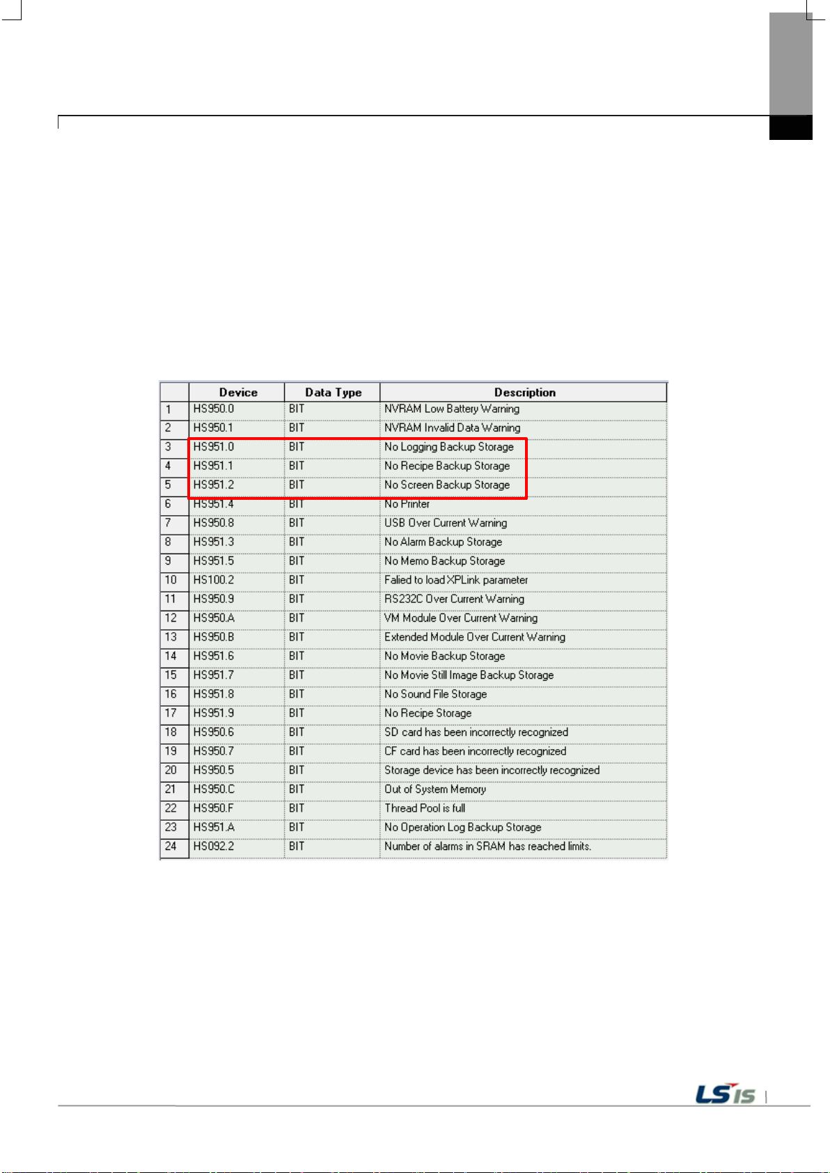
6-7
Chapter 6 Backup files by using Storage Devices
In case USB storage equipment is removed during operation after setting the path for saving Logging backup file as
USB storage equipment and downloading the project into device, the designated system alarm (HS951.0) is
case storage equipment is equipped again, alarm is reset.
In case USB storage equipment is removed during operation after setting the path for saving Recipe backup file as USB
storage equipment and downloading the project into device, the designated system alarm (HS951.1) is
equipment is equipped again, alarm is reset.
In case USB storage equipment is removed during operation after setting the path for saving Screen Image
backup file as USB storage equipment and downloading the project into device, the designated system alarm
(HS951.2) is set. In case storage equipment is equipped again, alarm is reset.
Internal address of the designated system alarm can be checked in XP-Builder as follows.
set. In case storage
set. In

7-1
(Within −15% / +10%)
panel.
compressed terminals.
Chapter 7 Maintenance
To keep the XGT Panel best, examine the XGT Panel.
Chapter 7 Maintenance
7.1 Maintenance
Because an error may be developed by environment, the periodic maintenance is needed. You should check the following
categories once or twice every 6 months.
Maintenance category Criterion Action
Power
Operating
temperature
Environment
Getting loose of power terminal There is no unwinding Screw the unwound terminal.
Getting loose of
communication connector
Reserved part
Gasket installation status
Operating
humidity
Vibration No vibration
Within the power change range
0 ~ + 50℃
10 ~ 85%RH
There is no unwinding Screw the unwound terminal.
Amount of reserved part and
reservation
Check the status
No gap between the gasket and
Modify the source of electric power in order to be in
the fluctuation range of a permissible voltage.
Modify the operating temperature and humidity to be
proper.
Use the anti-vibration rubber and make a count
measure.
Refill the insufficiency and improve the reservation.
Replace gasket or affix brackets firmly
Gasket status No damage or deterioration Replace gasket
7.2 Daily Maintenance
Check the followings daily.
Maintenance category Maintenance contents Criterion Action
Mounting status Check the brackets Should be mounted firmly Retighten screws
Loose terminal screws Not loose Retighten screws
Power terminal status
Communication connector
status
Indication LED Check the lighting Blue LED should be turned on Refer to the Appendix 1.
Touch panel surface state Check the tou ch panel
Reduce the distance between
Unwinding of fixed screw Not loose Retighten screws
Keep the proper distance. Correction
No pollution such as water drops or
oil
Surface wiping

7-2
Maintenance
method
matter adhesion
Screwdriver
Wind the fixed screw of
of power by test
Chapter 7 Maintenance
7.3 Periodical Maintenance
Check the followings once or twice every six months and take measure.
Maintenance category
Surrounding
Temperature
Environment
XGT Panel
Status
Connection
status
Power voltage maintenance
Surrounding
Humidity
Surrounding
pollution degree
Unwinding, swing Move XGT Panel Fixed firmly Retighten screws
Dust, foreign
Looseness
Reduce the distance
between compressed
terminals.
Loose connectors Visual check Not loose
Loose brackets
Measure through
Temperature
/Hygrometer Measure
of corrosive gas
Visual check Not loose Retighten screw with
Visual check
Retighten screw with
Screwdriver
Check the power
voltage of input terminal
Criterion Action
0 ~ 50 °C
10 ~ 85%RH
No corrosive gas.
Not loose Retighten screws
Keep the proper
distance.
Not loose Retighten screws
AC: 100~240V
DC: 24V
Modify it to meet
the general standard.
(Environment standard
in the panel)
Correction
connector
Supply
power modification
Check when battery is
exchanged and voltage
Battery
LCD Backlight maintenance Visual check
Touch status Touch Screen error Visual check
drop is indicated.
(It is expressed
by system alarm)
• Check the total of
power stoppage time
and guarantee
duration
• There is no battery
voltage drop indication
Check the guarantee
duration
No damage or
Scratches and Pollution
If guarantee duration is
exceeded even tough
there is no battery
voltage drop indication,
change the battery.
When error occurs,
change the backlight.
When error occurs,
change the Touch
Panel

7-3
over or it is out of order.
Chapter 7 Maintenance
Remark
(1) Battery exchange time is expressed by alarm. System alarm is expressed when system alarm
category is set at the XP-Builder as follows.
(2) Replac e Battery W ith Hitachi Maxell, Part No. CR2032 Only. Use of another battery may present a
risk of fire or explosion. Se e User Manual for safety Instructions.
WARNING: Battery may explode if mistreated. Do not recharge, disassemble or dispose of in fire.
(3) As the iXP2 model h as the in teg rat ed LCD a nd ba ckl ig ht , the LCD should be repl ace d w he n the l i fe i s

8-1
1. Emission
Conducted Disturbance
EN61000-6-4:2007 / A1 : 2011
C
Radiated Disturbance
EN61000-6-4:2007 / A1 : 2011
C
Harmonic Current Emission
EN61000-3-2:2014
N/T
Voltage Change, Fluctuations and Flicker
EN61000-3-3:2013
N/T
2. Immunity
EN61000-6-2:2005 / AC : 2005
EN61000-4-2:2009
EN61000-6-2:2005 / AC : 2005
EN61000-4-3:2006 / A1 : 2008 / A2 : 2010
EN61000-6-2:2005 / AC : 2005
EN61000-4-4:2004 / A1 : 2010
EN61000-6-2:2005 / AC : 2005
EN61000-4-6:2009
EN61000-6-2:2005 / AC : 2005
EN61000-4-8:2010
EN61000-6-2:2005 / AC : 2005
EN61000-4-5:2006
EN61000-6-2:2005 / AC : 2005
Chapter 8 EMC Standard Certification
Chapter 8 EMC Standard Certification
8.1 Requirement for EMC Standard Cert ification
EMC command is r egulated on “It doesn’t produce the Strong electromagnetic waves: Emission” and “It is not
affected by electrom agnetic wave f rom external: Im munity”. The fol lowing is des cribing the contents to meet the
EMC command when configuring the system by using the XGT Panel. This is a summary document for the
request and standard which our company has obtained from EMC but we don't assure that all devices
manufactured acc ording to thes e c ont ents are not su it abl e f or the be lo w sta nd ar d s . The final manufacturer needs
to finally judge about the fitness method or fitness judgment of EMC command.
8.1.1 CE Standard Certification
In case of XGT Panel, the EN610 00-6-4, EN61000 -6-2, EN61000-3-2, and E N61 000-3-3 of CE standards were
applied.
Applied Standards Results
Electrostatic Discharge
Radio-Frequency Electromagnetic Field
Fast Transient
Radio-Frequency Continuous Conducted
Power-Frequency Magnetic Fields
Surges
Voltage Dips and Interruptions
C=Comply NC=Not Comply N/T=Not Tested N/A=Not Applicable
EN61000-4-11:2004
C
C
C
C
N/T
C
N/T

8-2
Chapter 8 EMC Standard Certification
Directive:
Electromagnetic Compatibili ty Directive 89/336/EE C amended by the Di rective 93/68/EEC
8.1.2 KC Standard Certification
The XGT Panel acquire the electromagnetic fitness registration (KC specification) certified by wave laboratory
under information-communication part.
A grade device
This device acquires KC for industrial use.
If device is not purchased properly, exchange it to device for home use.
8.2 Requirement for Low Voltage Command Suitability
It is required to get the neede d Stabil ity fo r the devi ce operate d at AC50~10 00V, DC75~ 1500V’ s power. The following
describes attention about installa tio n and wi ring for t he suitability when u sing the XGT Pa nel. Th ough the fol lowing
data is made by requiremen t of regula tion and s tanda rd, we don’t gua rantee that all devi ces are sui table for the above
command. The method to be sui table fo r the EMC co mmand and judg ment of suit abili ty should be finally made by
device manufacturer himself.
8.2.1 Standard Certification for XGT Panel
XGT Panel is according to the EN61131-2:2007 (stability of device used in the measure, control laboratory).
8.2.2 Selection of XGT Panel
(1) iXP2-0800A, iXP2-1000A, iXP2-1200A, iXP2-1500A
Power module with rated input voltage of AC100 / 240V has hazardous voltage (voltage of 42.4V peak or more) inside.
Therefore, the CE marked p roduct is reinforced a nd insulated betw een the internal primary and secondary
(2) iXP2-0800D, iXP2-1000D, iXP2-1200D, iXP2-1500D
I/O modules with a DC 24V rating or les s are out of the low v oltage command tar get range.

App 1-1
Classification of problem
Description
☞
☞
☞
☞ Please refer to the 5. Communication problem.
☞ Please refer to the 6. USB Removal of Memory Card
☞
☞
☞
Appendix 1. Troubleshooting
Appendix 1 Troubleshooting
1. Type of Problems
It classifies problems from XGT Panel including an indicated figure, indication of the object, and problems
appeared when downloading. Refer to the following chart.
Problem when starting
Problem after the
monitor on
Display problem of
figure and object.
Communication problem
USB Removal of
Memory Card
External memory
recognition problem
Touch recognition problem
Error message
when executing program
Malfunction when starting.
Please refer to the 2. Problem when starting.
In case that there is no reaction when touching.
Please refer to the 3. Problem after the Monitor on.
In case that the figure or object is different from when editing.
Please refer to the 4. Indication problem of figure and object.
In case that communication is not executed properly.
In case that USB device is not working for a while when USB memory is
removed.
If external storage device such as USB, SD card is not recognized
Please refer to the7. External Memory Recognition.
If the touch is not recognized normally
Please refer to the 8. Touch recognition.
In case that an error message occurs when operating the XGT Panel.
Please refer to the 9. Error message when executing program.

App 1-2
Display color
Contents
Power is supplied to XGT Panel
Appendix 1. Troubleshooting
2. Problems when Starting
Why does black screen show up when turning on the device?
Phenomenon: When turning on the device, black screen shows up and the booting is impossible.
< Cause >
(1) Because the device is not set as a booting mode.
(2) Black screen may appear because of malfunction of backlight.
<Solution>
(1) Because the device is not set as a booting mode, the above problem can occur.
Check whether No. 5 switch at DIP switch in the back of the device is in B direction or not.
B direction is a booting mode.
When is the color of LED changed?
Please check the followings.
BLUE
When applying the option, ‘Go to Screen after boot up’, it displays “Failed to load image files” as the
monitoring has not been started.
Phenomenon: After storing images in the USB storage device and then selecting the option “Go to Screen
after boot up” in the start menu, in case when re-permitting the power of the equipment, the message like
“Failed to load image files” is displayed and the monitoring is not started.
<Cause>
(1) In case when it is connected with the USB storage device, the recognition of the USB is delayed.
<Solution>
(1) In case when the recognition speed is delayed due to the characteristics of the USB storage device,
remove the USB storage device and then reinstall it.
When the power is re-permitted, the USB storage device (or USB mouse) is not recognized.
Phenomenon: When the USB storage device was initially installed, it was normally recognized. However, it is
not recognized after the power is re-permitted.
<Causes>
(1) Due to the option of the ‘Reset USB Power’ of the equipment, there could problems in the recognition
process.
(2) Depending on the USB storage device, it may not be smoothly recognized.

App 1-3
Appendix 1. Troubleshooting
<Solution>
(1) If the power initialization option(“Reset USB Power”) of the equipment is selected, cancel the selection
and then permit the power again. The “Reset USB Power” option is an additional function to improve
the initialization of the storage device with slow recognition speed or low recognition ratio. Depending
on the characteristics of the storage device, however, the power initialization can be an obstacle to the
initialization work. Thus, depending on Phenomenon, select what has higher recognition ratio by
properly using the power initialization option.
(2) Depending on the characteristics of the storage device, it may not be recognized. Use another USB
storage device showing higher recognition ratio.

App 1-4
Appendix 1. Troubleshooting
3. Problems after the Monitor on
When touching the screen it reacts in a different area or it may not react at all?
Phenomenon: When touching the screen it reacts in a different area or it may not react at all.
< Cause >
(1)Touch’s Calibration setting is not proper.
(2) Touch panel may be a break down.
<Solution>
(1) Redo Calibration setting about touch. Refer to the [Device manual Ch.4.1 Touch Calibration].
(2) It you can’t go to setting menu, connect mouse to USB port and use mouse.
Buzzer does not sound.
Phenomenon: When pressing buzzer, buzzer does not sound.
< Cause >
(1) When that the switch operates but the buzzer doesn’t sound, the buzzer is set as no sound.
(2) If the switch doesn’t work too, it seems that some error occurs in the touch function.
<Solution>
(1) Redo environment setting for buzzer to sound. Refer to the [device manual Ch.4.7 Environment Setting].
(2) After setting to use buzzer, check whether the buzzer sounds or not in the 1)’s setting windows.
Phenomenon: After the system alarm about the lack of system memory occurs, XGT Panel itself closes the
monitoring and then moves to the start menu in unspecific time without user’s operation.
<Causes>
(1) The memory usage could be exceeding 95%.
(2) The memory usage can be a bit increased when floating pop-up windows or moving to several screens
during monitoring. In case when the number of image used for project is a lot, the memory usage can
more easily reach the limit. In this case, XGT Panel closes the monitoring by itself and then takes an
action to secure the memory again.
<Solution>
(1) In case of using vector image instead of raster image, the memory share can be reduced. In the graphic
library of XP-Builder, the image group marked as OOO_R is the raster image group while the image
group marked as OOO_V is the vector image group.
(2) In case when the monitoring is closed down due to the increase of the memory share in spite of the
image change operation, contact the A/S center close by.
App 1-5
Appendix 1. Troubleshooting
After continuously adding projects to the screen, and adding/editing objects, the operation speed has
been slowed down.
Phenomenon: After adding projects to the screen and also adding/editing objects, it feels like the operation
speed of XGT Panel gets slowed down.
<Causes>
(1) The amount of image used for projects is big.
(2) In order to increase the screen operation speed, XGT Panel maintains the used images in the memory in
advance. Since the memory resource has limitation, they cannot be maintained in the memory once the
amount of image exceeds a certain limit. Whenever they are needed, thus, they are read from the file
system and then expressed on the screen. This could be the reason why the screen operation speed gets
slowed down.
<Solution>
(1) In case of using vector image instead of raster image, the memory share can be reduced. In the graphic
library of XP-Builder, the image group marked as OOO_R is the raster image group while the image
group marked as OOO_V is the vector image group.
(2) In case when there is no proper vector image, the desired image can be composed by using various
functions of figures (circle, square, straight line and etc.).
(3) Removing unnecessary background screen, the screen is composed by applying the background colors.

App 1-6
Bit Switch
The switch is expressed but it doesn’t work.
Word Switch
The switch is expressed but it doesn’t work .
Change Screen Switch
The switch is expressed but it doesn’t work.
Special Switch
The switch is expressed but it doesn’t work.
Multi Switch
The switch is expressed but it doesn’t work.
Bit Lamp
Image is not shown.
N-State Lamp
Image is not shown.
Clock
Present time is shown.
as it is.
as it is.
as it is.
as it is.
Character string is n ot shown. W hen designat ing the back ground image, image is
shown as it is.
Character string is n ot shown. W hen designat ing the back ground image, image is
shown as it is.
The window screen set in the obj ect is not s hown. B ut if comm unicatio n is set wit h
other object in the same window screen, it can be shown by that object.
The window screen set in the obj ect is not s hown. B ut if comm unication is set wit h
other object in the same window screen, it can be shown by that object.
The part screen s et in the object is not sho wn. But if communication is set with
other object in the same part screen, it can be shown by that object.
Word Part
The part screen set in the object is not shown.
Appendix 1. Troubleshooting
4. Display Problem of Figure a nd Object
The shape of object is not shown or the number or character value which has to be shown is not shown.
Phenomenon: The shape of object is not shown or the number or character value which has to be sho wn is
not shown.
<Cause>
(1) The connection with PLC connected with each project is disconnected or NAK occurs.
<Solution>
(1) When the communication is executed at first, Check the cable connected with PLC is OK or not.
(2) If object where the offset is set is not shown, check whether address range is exceeded or not.
(3) In case that comm unication is not OK, when c ommunication is abn ormal, the following m essage shows
up in the XGT Panel.
Object type Phenomenon
Word Lamp Image is not shown.
Bit Message
Word Message
Numeric Display
Numeric input
Text Display
Message is not sho wn. W hen designat ing the back ground im age, im age is sho wn
Message is not sho wn. W hen designat ing the back ground im age, im age is sh own
The value is not shown. W hen d es ig nat ing t he b ac kground image, image is sho w n
The value is not shown. W hen d es ig nat ing t he b ac kground image, image is sho w n
Text Input
Bit Window
Word Window
Bit Part

App 1-7
But if communicatio n is set with other object in the s ame part screen, it can be
shown by that object.
Animation
Animation is not shown.
it is.
it is.
it is.
Graph is not shown. W hen designat ing the back ground im age, im age is shown as
it is.
X, Y axis is shown normally but trend axis is not normally shown.
When designating the background image, image is shown as it is.
Change doesn’t occur. When communication is abnormal, alarm occurs because it
it is.
shown normally. But, log data is shown as # when communication is abnormal.
Change doesn’t occur . Because it shows the group of alarm already developed,
shows the name of group where each alarm is included.
Object type Phenomenon
Appendix 1. Troubleshooting
Bar Graph
Pie Graph
Meter Graph
Closed Graph
Trend Graph
History Alarm Viewer
Data list
Logging Viewer
Navigator
The number indication object value is shown as # or ~.
Phenomenon: The number indication object value is shown as # or ~.
(Same phenomenon occurs at the number input device, viewing data list, and viewing logging)
<Cause>
(1) This happens when digit is not correct or type is not BCD.
<Solution>
(1) When the number t o be expressed ex ceeds the num ber set in the objec t, # is expr essed. In cas e of this,
set the digit largely and after download again, execute program again.
(2) When the numeric display object is expressed as BCD type, the data whose type is not BCD is
expressed as ~. In case of this, adjust device value as BCD type.
(3) This phenomenon occurs at the data list object, numeric input, numeric display device, and logging
viewer.
Graph is not shown. W hen designat ing the back ground im age, im age is shown as
Graph is not shown. W hen designat ing the background im age, image is shown as
Graph is not shown. W hen designat ing the back ground im age, im age is shown as
can’t know the status of ala rm target device . But prev ious al arm data s hows up as
Value is not shown. Lattice of viewing data list of object is shown as it is.
Change doesn’t occur . When comm unication is normal, the recorded log data is
though communication is abnormal, if it has alarm data already developed, it

App 1-8
Appendix 1. Troubleshooting
After switching the screen, the previous screen remains for a few minute.
Phenomenon: After switching the screen, when there is no background or image in the part or number
indication device, the previous screen remains for a few minute because of change of part.
< Cause >
(1) After switching the screen, when connection is set up multiply or communication time-out occurs, the
screen of previous part remains in some object.
<Solution>
(1) It is normal stat us. In case that multiple connec tion or communication is not good, when switching the
screen, the remains of previous screen can occur during the time-out hour.
The folded object doesn’t sequentially show up.
Phenomenon: The number under the data list shows up above data list.
< Cause >
(1) The device value is expressed at the top of object screen.
<Solution>
(1) It is normal status. T he f olded windo w or part o bject is not include d in scr een, regard less of s equence of
drawing, the object cha nged recently is expr essed at top of sc reen. So if possible, do n ot fold the object
in screen.
The object always shows up above the figure.
Phenomenon: I downl oaded the f igure above the object in XP-Builder, but the ob ject always sho ws up abov e
the figure.
< Cause >
(1) In XGT Panel, The object always shows up above the figure.
<Solution>
(1) It is normal status. The object always shows up above figure in the XGT Panel.
App 1-9
Appendix 1. Troubleshooting
5. Communication Problems
It seems that communication does not work.
Phenomenon: On the scre en where the object is not many, communication works but when you move the
screen where the object is many, timeout occurs.
< Cause >
(1) In the device setting, the communication time-out is set to be too short.
<Solution>
(1) It occurs because timeout is set much smaller than sum of request time of communication data and
response time from PLC. In the device settin g at the XP-Build er, after setting co mmunication tim e out to
be big, download program and execute aga in.
It seems that communication doesn’t work.
Phenomenon: Comm unic ation doesn ’t wor k.
< Cause >
(1) Communication setting or cable may be not normal.
<Solution>
(1) In case of RS-232C, check whether connection setting is normal or not in XP-Builder.
(2) In case of RS-422/485, check whether station and communication connection setting is normal or not.
(3) If 1), 2) is normal, do diag nosis about PLC-RS232C, PLC-RS48 5/422 at the Serial diagnosis scr een of
device menu. Refer to the [Device manual ch.5.6 Serial Communication Diagnosis]
(4) If 3) is normal, check whether connection cable has error or not.
(5) In case of Ethernet, check the port and IP setting about relative PLC.
(6) In case of Ethernet, make sure that the IP and port settings for the other PLC are correct.
It seems that communication doesn’t work.
Phenomenon: Ethernet communication is connected slowly after monitoring starts.
< Cause >
(1) Subnet of Ethernet port is the same.
<Solution>
(1) If the subnets of the two Ethernet ports are the same, the initial connection may be delayed due to
the seek time.
(2) If possible, remove the Ethernet port's subnet.
► Befor e trial operation of the product, be sure to check if a normal comm unication is available
between XGT Panel and the subject device of control
Caution

App 1-10
Appendix 1. Troubleshooting
6. USB Removal of Memor y Card
When removing the USB memory equipment, device is stopped for some times.
Phenomenon: This happens when doing data backup including logging, recipe.
< Cause >
(1) This happens because memory card is removed when doing data backup.
<Solution>
(1) If possible, when monitoring XGT Panel, do not remove the memory card and after going out to the
waiting screen, execute the removing.
(2) Inescapably you have to remove it during the operation, remove when backup does not occur. If the
above phenomenon occurs, it works normally after about 10 seconds.
(3) In case of USB memory, please remove it when the LED of USB external memory is not flickering.
After the repeated attachment/detachment of the USB storage device, it is not recognized.
Phenomenon: It can happen when the attachment/detachment of the USB device is repeated for a short
period of time.
<Cause>
(1) When the USB device is recognized or removed, it takes a certain period of time(maximum a few
seconds) to recognize it. When the storage device is quickly installed/removed, however, it cannot be
normally recognized.
<Solution>
(1) It is recognized again after waiting for about a minute. Install it again after waiting for more than a minute.
(2) When removing/reinstalling the USB device, reinstall it after waiting for around 2-3 seconds.
Caution
► If you force to remove the dat a during the storage of data in the external m emory, file may not
be stored in a normal condition or external memory may suffer from damage.

App 1-11
► If you forcefully remove the data from the external memory while it is being saved, the file may not be
► If you need to clean the unit, be sure to turn off the power before cleaning.
7. External memory recognition
USB, SD Card not recognized.
Phenomenon: The USB or SD card is inserted but the unit does not recognize it.
<Cause>
(1) It appears when the USB memory or SD card is partitioned.
<Solution>
(1) Please format USB memory or SD card as one partition.
Appendix 1. Troubleshooting
Caution
saved properly or the external memory may be damaged.
8. Touch recognition
It recognizes that you have touched a place you do not want.
Phenomenon: The place where I did not touch was touched.
<Caution>
(1) Check the surface of the touch panel for foreign matter such as water or oil.
(2) Check if the power or communication cable is passing on the surface of the touch panel.
<Solution>
(1) Clean the surface of the touch panel using a dry cloth or a towel
(2) When cleaning the surface of the touch panel, be sure to turn off the power to prevent malfunction
(3) Be careful not to let cables run near the touch panel
Caution
► The electrostatic touch panel may cause malfunction if liquids such as water or oil get on the surface.

App 1-12
Occurren
location
Customer Service Center.
Backup data is not valid. If this
power and exchange the battery.
The built-in Flash disk has an error.
Center.
Center.
problem.
problem.
Input the effective time.
There is no setting information data of
the near Customer Service Center.
Please enter an
255.
When setting IP, the values within
within the above range.
Appendix 1. Troubleshooting
9. Error Message during Execution of Programs
In case that prob lems occur during ex ec ut ion of X GT Panel including the s tart of device, diag nos is of device and
environment setting, proj ect download, monitoring of control device, and error messages occur as type of box. At
this time the mess age indicates the code made b y 4 digit number. The front 2 num ber indicate code of objec t
and work, the rear 2 num ber is m essage num ber. In case that the pres ent error message is indicated as [0101],
an error message oc curs when doing diagnosis about the status of NVRAM. When an error message occ urs,
refer to the row’s number and sequence and find the category of reason and measure.
Error code
Object
Type Address
0x01
ce
XGT
Panel
Error message Reason and measure
Failed to check whether backup
NVRAM Data
Access ... FAILED!
memory is normal or not. If this
symptom is repeated, contact the near
Device
diagnosis
0x01
0x02
0x03
0x04
0x05
0x06
0x01
XGT
Panel
XGT
Panel
XGT
Panel
XGT
Panel
XGT
Panel
XGT
Panel
BATTERY STATUS ...
NOT GOOD!
Write Operation
FAILURE!
Read Disk Information
Error!
Write Operation
FAILURE!
Read Disk Information
Error!
Invalid timeout value.
symptom is repeated when turning
power off and on, remove XGT Panel’s
Contact the near Customer Ser vice
The built-in Flash disk has an error.
Contact the near Customer Ser vice
Check that CF card is empty, and equip
CF card and test again. If same
symptom is repeated, CF card or CF
card slot of XGT Panel may have a
Check that CF card is empty, and equip
CF card and test again. If same
symptom is repeated, CF card or CF
card slot of XGT Panel may have a
You inputted the wrong time which is
not within backlight setting time range.
Device
setting
0x02
0x02
0x03
XGT
Panel
XGT
Panel
Not found XGT Panel
configuration file.
integer between 0 and
XGT Panel. If this symptom is repeated
when turning power off and on, contact
0~255 are effective. Input the value

App 1-13
Occurren
location
information
Download the project from XP-Builder.
Because of update error or Flash disk
Service Center.
There is password in the each object.
property information.
Because of communication error, the
communication status and input again.
XGT
Panel
You tried to input with no value. Input
the value
XGT
Panel
Exceeded the max
length.
You exceed the maximum length to
input.
Panel
minimum Value.
input.
Panel
maximum Value.
input.
Builder and input again.
Character
input device
Message
0x09
None
Clock
0x0A
None
Animation
0x0B
None
Graph
0x0C
None
Window
0x0D
None
Part
0x0E
None
History
alarm
Flow alarm
0x20
None
Object
Error code
Type Address
ce
Appendix 1. Troubleshooting
Error message Reason and measure
Viewing
device
XGT Panel
Update
Switch h05 h01
Number
indication
device/
Number
input device
0x03 0x01
0x04 0x01
0x06
h01
h02
0x03
0x04
0x05
XGT
Panel
XGT
Panel
XGT
Panel
XGT
Panel
XGT
XGT
No project in XGT
Panel.
Failed to Start engine.
Please update engine
again.
Invalid password.
Can't write Data.
No input Data.
Exceeded the
Exceeded the
Now, there is no downloaded project so
you can’t see connection information.
error, program can’t be executed. If you
can update, redo the above procedure.
If you can’t, contact the near Customer
When editing the project downloaded in
the present device, input the
designated password at the project
value can’t be inputted. Check the
You exceed the maximum value to
You exceed the minimum value to
0x06
Lamp 0x07 None
indication
device/
Character
0x08 None
0x0F None
XGT
Panel
Invalid at Input Case.
When you input the value, input can’t
be done because of wrong input. Check
the input condition of each object in the

App 1-14
Occurren
location
alarm
related
related
Abnormal send-
again.
This message shows up when making
password.
It make new password setting file when
near Customer Service Center.
Invalid Backup Media.
Communication status is abnormal.
Center.
In case that the version information file
Service Center.
There is version information file. In
Customer Service Center.
Appendix 1. Troubleshooting
Error code
Object
Type Address
ce
Error message Reason and measure
System
Scheduler
Recipe
Logging
related
Data list 0x25 None
0x21 None
0x22 None
0x23 None
0x24 None
0x00
0x01
0x02
XGT
Panel
XP
Builder
XP
Builder
payload. Please
download project
There's not Password
File.
Failed to Create
Password File.
Communication status is abnormal.
Check the connection of
communication cable.
it newly because there is no password
setting file in the device. When mak ing
it newly, it is initia l i zed w it h no
there is no password setting file. But
downloading is stopped when it fails to
make this file because of device error.
If this problem is repeated, Contact the
Project
download
0x26
0x03
0x04
0x05
XP
Builder
XP
Builder
XP
Builder
Failed to Create
version File.
File Size Error.
Route information is not correct to save
project data. If this problem is repeated,
Contact the near Customer Ser vice
doesn’t exist in the device, that file is
made newly. In case that the device
has error and fails to make that file,
download is stopped. If this problem is
repeated, Contact the near Customer
case that because of error of device, it
fails to read version information,
because the device doesn’t know
version, download is stopped. If this
problem is repeated, Contact the near

App 1-15
Occurren
location
Center.
In case of not reading information about
Customer Service Center.
Project is set to store data at CF card
Customer Service Center.
Project is set to store data at USB
Center.
In case that it can’t know information
contact Customer Service Center.
In case that because of error of Flash
contact Customer Service Center.
In case that it fail to delete the font file
Service Center.
Object
Error code
Type Address
0x06
ce
XP
Builder
Appendix 1. Troubleshooting
Error message Reason and measure
In case of not reading file where project
Failed to get Project
ID.
property is included, download is
stopped. If this problem is repeated,
Contact the near Customer Ser vice
Project
download
0x26
0x07
0x08
0x09
0x0A
XP
Builder
XP
Builder
XP
Builder
XP
Builder
Failed to read history
alarm data.
Failed to read CF
Card information.
Failed to read USB
information.
Failed to read Flash
memory information.
alarm history because of error of
NVRAM, download is stopped. If this
problem is repeated, Contact the near
equipped at device. By the way, now it
can’t read information about CF card.
Check the installation status of CF card
and if it is normal, check the CF card. If
this problem is repeated, contact
storage device equipped at device. By
the way, now it can’t read information
about USB storage device. C heck the
installation status of USB storage
device and if it is normal, check USB
storage device. If this problem is
repeated, contact Customer Service
about memory status, download is
stopped. If this problem is repeated,
0x0B
0x0C
XP
Builder
XGT
Panel
Failed to clear Temp
Directory.
Failed to delete Font
File. Please reboot
XGT Panel.
Disk, it can’t delete the directory made
temporally for download because of
error of Flash Disk, download is
stopped. If this problem is repeated,
of previous project because of error of
XGT Panel, download is stopped. If this
problem is repeated, contact Customer

App 1-16
Occurren
location
Customer Service Center.
In case that it fail to delete the sound
Customer Service Center.
It can’t download part or fixed part in
Service Center.
Customer Service Center.
The project backup file downloaded
Customer Service Center.
When downloading, the log data area in
contact Customer Service Center.
contact Customer Service Center.
Appendix 1. Troubleshooting
Error code
Object
Type Address
0x0D
Panel
ce
XGT
Error message Reason and measure
In case that it fail to delete the image
Failed to delete Image
File. Please reboot
XGT Panel.
file of previous project because of error
of XGT Panel, download is stopped. If
this problem is repeated, contact
0x0E
0x0F
0x10
0x11
XGT
Panel
XGT
Panel
XP
Builder
XGT
Panel
Failed to delete Sound
File. Please reboot
XGT Panel.
There's no
downloaded project. It
needs to download
whole project
Backup path is invalid.
Please check the path
that project is
downloaded.
Failed to delete
previous project
archive. Please reboot
XGT Panel.
file of previous project because of error
of XGT Panel, download is stopped. If
this problem is repeated, contact
case there is no downloaded project. In
case of this, download again. If this
problem is repeated, contact Customer
When user change the storage location
of project data including image and
font, if there is not respective routine, it
make newly. By the way, download is
stopped in case it fails to make newly.
When it is designated as CF card, it
can occur in case CF card is not
installed. If this problem is repeated
and not referred in the above, contact
already can be deleted because of
error of XGT Panel. Reboot XGT Panel.
If this problem is repeated, contact
0x12
Project
download
0x26
0x15
XGT
Panel
XGT
Panel
Failed to delete past
project data files.
Please download
project again.
Failed to initialize
LOGGING area in NV
RAM. Please
download project
again.
the NV-RAM is initialized in case of
selecting previous project’s the monitor
data deletion option. By the way, in
case of failing this, downloading is
stopped. If this problem is repeated,
When downloading, the log data area in
the NV-RAM is initialized in case of
selecting previous project’s the monitor
data deletion option. By the way, in
case of failing this, downloading is
stopped. If this problem is repeated,
 Loading...