


5.5~18.5kW(200V), 5.5~90kW(400V)
AC Variable Speed Drive
H100 Troubleshooting Manual
Safety Instructions
Read this manual carefully before servicing or inspecting this equipment.
Keep this manual within easy reach for quick reference.

1
Quick Reference Table
The following table listed situations frequently encountered while working with inverters. Refer to
the typical situations to quickly and easily locate solutions to your questions.
Situation
Reference
The motor is too noisy.
P. 33
I want to review recent fault trip and warning histories.
P. 18
The motor is producing too much heat.
P. 31
The cooling fan is not working.
P. 34
I want to know how I can keep the inverter when I am not using it.
P. 44
I want to initialize all parameters.
P. 16
I want to terminate the inverter.
P. 44
I want to review the input/output module.
P. 38
I want to change the fan when it exceeded the replacement period.
P. 42
I want to change the carrier frequency.
P. 14
I cannot set the parameters.
P. 30
The motor is not working.
P. 30
The motor stops when it is connected to the load or accelerated.
P. 32

2
Contents
INTRODUCTION 3
Manual Composition 3
PRODUCT IDENTIFICATION 4
ASSOCIATION MANUAL 4
SAFETY INFORMATION 5
REVISION RECORD 7
1
BASIC CHECKLIST 8
Before you think it failed 8 1.1
Basic Operations 10 1.2
Parameter Change 14 1.3
Carrier Frequency Change 14 1.3.1
Initializing All Parameters 16 1.3.2
Read and Write Parameters 17 1.3.3
Fault Trip Monitoring 18 1.4
2
TROUBLESHOOTING 21
Trips and Warning 21 2.1
Failure/Warning List 21 2.1.1
Troubleshooting Fault Trips 25 2.1.2
Troubleshooting Other Fault 30
2.2
3
MAINTENANCE 35
Regular Inspection List 35 3.1
Daily Inspections 35 3.1.1
Annual Inspections 36 3.1.2
Bi-Annual Inspections 37 3.1.3
Check Input/Output Module 38 3.1.4
Replace Cooling FAN 42 3.1.5
Storage and Disposal 44 3.2
Storage 44 3.2.1
Disposal 44 3.2.2

3
Introduction
Manual Composition
1.1 Before you think it failed
1.2 Basic Operations
1.3 Parameter Change
1.3.1 Carrier Frequency Change
1.3.2 Initializing All Parameters
1.3.3 Read and Write Parameters
1.4 Fault Trip Monitoring
2.1 Trips and Warning
2.1.1 Failure/Warning List
2.1.2 Troubleshooting Fault Trips
2.2 Troubleshooting Other Fault
3.1 Regular Inspection List
3.1.1 Daily Inspections
3.1.2 Annual Inspections
3.1.3 Bi-Annual Inspections
3.1.4 Check Input/Output Module
3.1.5 Replace Cooling FAN
3.2 Storage and Disposal
3.2.1 Storage
3.2.2 Disposal
This section explains troubleshooting
fault trips and other common faults.
If problems are not solved, please
contact your vendor or LSIS.
This section provides information
on how to maintain the inverters on
a regular basis for different time
periods.
When there is a problem in the
inverter, please check the
input/output module. This is the
basic method to check the
hardware.
This section covers check points
when there is a problem in the
inverter.
Then check the parameter settings
using basic operations and the trip
records.
2 Troubleshooting
1 Basic Checklist
3 Maintenance

4
Product Identification
Note
The H100 75/90 kW, 400 V inverters satisfy the EMC standard EN61800-3 without installation of optional EMC
filters.
Association Manual
H100 user manual can be downloaded through LSIS homepage.
Link : http://www.lsis.com/support/download/

5
Safety Information
Read and follow all safety instructions in this manual precisely to avoid unsafe operating conditions,
property damage, personal injury, or death.
Safety symbols in this manual
Danger
Indicates an imminently hazardous situation which, if not avoided, will result in severe injury or
death.
Warning
Indicates a potentially hazardous situation which, if not avoided, could result in injury or death.
Caution
Indicates a potentially hazardous situation that, if not avoided, could result in minor injury
or property damage.
Safety information
Danger
Do not open the cover of the equipment while it is on or operating. Likewise, do not operate
the inverter while the cover is open. Exposure of high voltage terminals or charging are to the
external environment may cause an electric shock. Do not remove any covers or touch the
internal circuit boards (PCBs) or electrical contacts on the product when the power is on or
during operation. Doing so may cause serious injury, death or serious property damage.
Do not open the cover of the equipment even when the power supply to the inverter has been
turned off unless it is necessary for maintenance or regular inspection. Opening the cover
may lead to an electric shock even when the power supply is off.
The equipment may hold charge long after the power supply has been turned off. Use a multi-
meter to make sure that there is no voltage before working on the inverter, motor, or motor
cable.

6
Warning
This equipment must be grounded for safe and proper operation.
Do not supply power to a faulty inverter. If you find that the inverter is faulty, disconnect the
power supply and have the Inverter repaired.
The Inverter becomes hot during operation. Avoid touching the Inverter until it has cooled
down to avoid burns.
Do not allow external objects, such as screws, metal chips, debris, water, or oil to get inside
the Inverter. Allowing external substances inside the Inverter may cause the Inverter to
malfunction or ignite fire.
Do not operate the Inverter with wet hands. Doing so may cause electric shock.
Caution
Do not modify the interior structure/components of the Inverter. Doing so will void the
warranty.
The Inverter is designed for 3-phase motor operation. Do not use the Inverter to operate 3-
phase motor.
Do not place heavy objects on top of electric cables. Doing so may damage the cable and
cause an electric shock.

7
Revision Record
Version
Date
Changed main contents
Reference Page
V1.0
2016.10
1. First edition
-

8
1
Basic Checklist
Before you think it failed 1.1
Items
Check Point
Result
Installed
Environment /
Input/Output
voltage
Is the installed location appropriate?
Does the environment meet the inverters operating conditions?
Does the power source match the inverter’s rated input?
Is the rated output of the inverter sufficient to supply the equipment?
Power Terminal
Wiring
Is the circuit breaker installed on the input side of the inverter?
Is the circuit breaker correctly rated?
Are the power source cables correctly connected to the R/S/T terminals
of the inverter?
(Caution: Connecting the power source to the U/V/W terminals may
damage the inverter)
Are the motor output cables connected in the correct phase rotation
(U/V/W)?
(Caution: Motors will rotate in reverse direction if three phase cables are
not wired in the correct rotation)
Are the cables used to connect power terminals correctly rated?
Is the inverter grounded properly?
Are the power terminal screws and the ground terminal screws tightened
to their specific torques?
Are the overload protection circuits installed correctly on the motors (if
multiple motors are running using one inverter)?
Is the inverter separated from the power source by a magnetic contactor
(if a braking resistor is in use)?
Are advanced-phase capacitors, surge protection and electromagnetic
interference filters installed correctly?
(These devices MUST NOT be installed on the output side of the
inverter)

1. Basic Checklist
9
Items
Check Point
Result
Control Terminal
Wiring
Are STP (shielded twisted pair) cables used for control terminal wiring?
Is the shielding of the STP wiring properly grounded?
If 3-wire operation is required, are the multi-function input terminals
defined prior to the installation of the control wiring connections?
Are the control cables properly wired?
Are the control terminal screws tightened to their specified torques?
Is the total cable length of all control wiring less than 165ft (50m)?
Is the total length of safety wiring less than 100ft (30m)?
Miscellaneous
Items
Are optional cards connected correctly?
Is there any debris left inside the inverter?
Are there any cables (contacting adjacent terminals) creating a potential
short circuit risk?
Are the control terminal connections separated from the power terminal
connections?
Have the capacitors been replaced if they have been in use for more
than 2 years?
Has a fuse been installed for the power source?
Are the connections to the motor separated from other connections?

1. Basic Checklist
10
Basic Operations 1.2
Key Functions
Refer to the following illustration to identify part names and functions
Operation Keys
The following table lists the names and functions of the keypad’s operation keys.
Key
Key Name
Function Description
[MODE] Key
Used to switch between modes.
[PROG / Ent] Key
Used to select, confirm, or save a parameter value.
[Up] key
Switch between codes or increase or decrease parameter values.
[Down] key
[Left] key
[Right] key
Switch between codes or increase or decrease parameter values.
[MULTI] Key
Used to perform special functions, such as user code registration.
[ESC] Key
Used to cancel an input during parameter setup.
Pressing the [ESC] key before pressing the [PROG / ENT] key reverts the
parameter value to the previously set value.
Pressing the [ESC] key while editing the codes in any function group
makes the keypad display the first code of the function group.
Pressing the [ESC] key while moving through the modes makes the
1. ESC Key
2. LEFT Key
3. MODE Key
4. HAND mode LED indicator
5. HAND Key
6. OFF mode LED indicator
7. OFF Key
8. DOWN Key
9. AUTO Key
10. AUTO mode LED indicator
11. MULTI Key
12. RIGHT Key
13. PROG / Ent Key
14. UP Key

1. Basic Checklist
11
keypad display Monitor mode.
[HAND] Key
Used to switch to HAND (local/manual) operation mode.
[OFF] Key
Used to switch to OFF (standby) mode or to reset the inverter faults.
[AUTO] Key
Used to switch to AUTO (remote) operation mode.

1. Basic Checklist
12
Inverter Operating Status
Multi-function Key
Composition of Display
(1) Monitor Mode
(2) Parameter change display
Display Item List
The following table lists the functions and description of the keypad displays characters.
No.
Function
Display
Description
1
Mode
Display
MON
Monitor Mode
PAR
Parameter Mode
U&M
USR & Macro Mode
TRP
Trip Mode
CNF
Config Mode
2
Operating
Command
K
Keypad operation command
O
FieldBus communication option operation command
A
Application option operation command
E
Time Event operation command
R
Built-in 485 operation command
T
Terminal block operation command
2
Frequency
Command
K
Keypad frequency command
V
V1 input frequency command
I
I2 input frequency command
P
Pulse input frequency command
U
Frequency command during UP operation
Monitor Mode Cursor
Status Display Item
Monitor Mode Display Item 1
Monitor Mode Display Item 2
Monitor Mode Display Item 3
Mode Display
Code No. and Name
Initial Value at the Time
of Product Delivery
Inverter Operating Status
Status Display Item
Parameter Value
Settable Range
Currently Set Value
Mode Display
Operating/Frequency
Group Display
Multi-function Key
Rotational direction
Rotational direction

1. Basic Checklist
13
(Up-Down operation)
D
Frequency command during DOWN operation
(Up-Down operation)
S
Frequency command during STOP operation
(Up-Down operation)
O
FBus Option frequency command
J
Jog frequency command
R
Internal 485 frequency command
1 ~7
Multi-step frequency command
3
Multi
Function
Key Setting
UserGrp
SelKey
Used to register parameters as a user group in the parameter
mode or delete parameters in the user group.
4
Inverter
Operating
Status
STP
Motor stopped
FWD
Operating forward
REV
Operating reversely
Forward command given
Reverse command given
DC
DC outputting
WAN
Warning
STL
Stalling
SPS
Speed Searching
OSS
Software Over Current controlled
OSH
Hardware Over Current controlled
TUN
Auto Tuning
PHT
Pre-heat
FIR
Fire mode operation
SLP
Sleep mode operation
LTS
Load tuning
CAP
Capacity diagnostics
PCL
Pump clean
1. Basic Checklist
14
Parameter Change 1.3
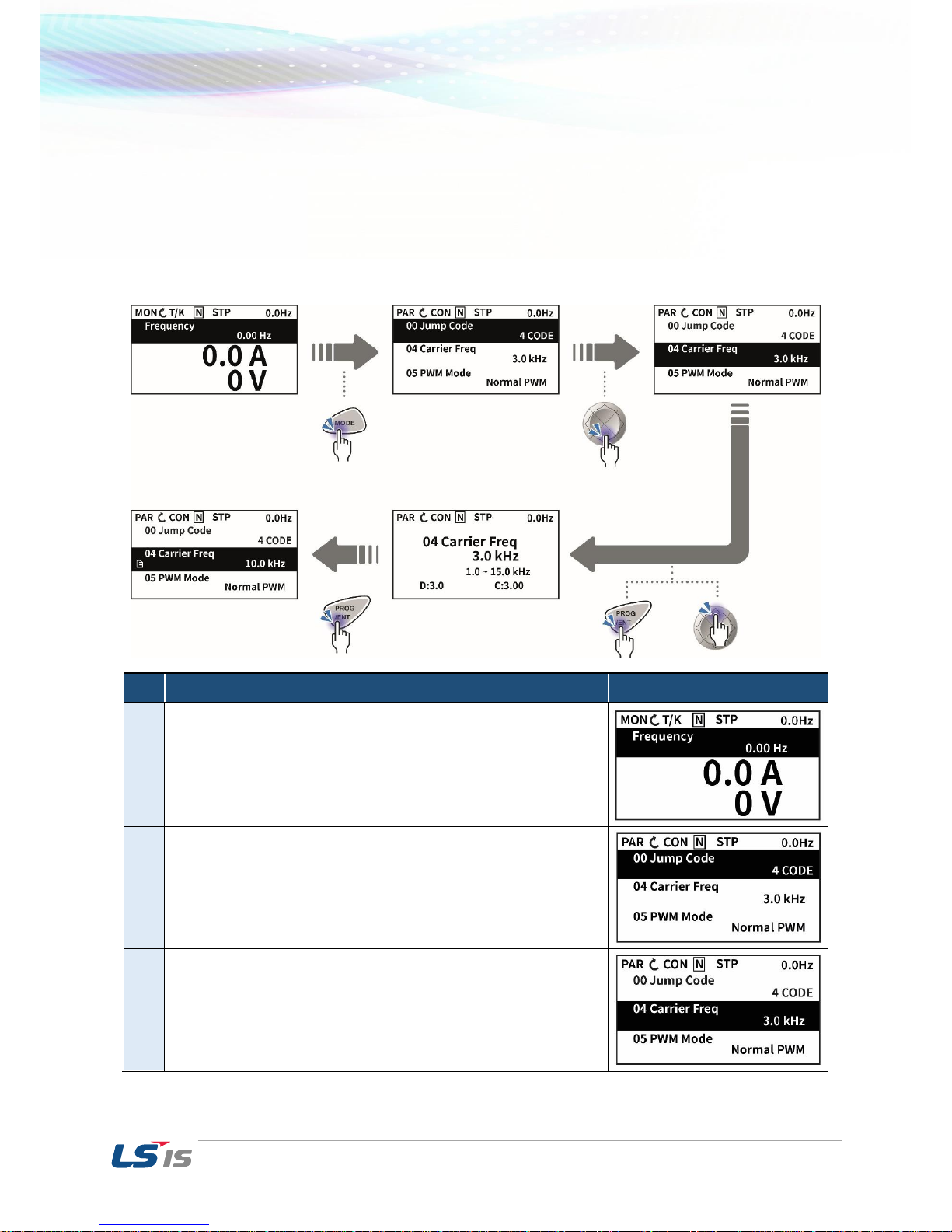
Carrier Frequency Change 1.3.1
The following example demonstrates how to configure Carrier Frequency by modifying CON group 04
code(Carrier Frequency) from 3.00(Hz) to 10.00(Hz). You can configure the parameters for different
codes in any other group in exactly the same way.
Step
Instruction
Keypad Display
1
Monitor Mode is displayed.
2
Shift to CON by using Mode key.
3
Shift to code 04 using Down key.
Press PROG.

1. Basic Checklist
15
4
Change the Carrier Frequency to 10 using Up key.
Press ENT.
5
The display come back to the initialization selection after
finishing Carrier Frequency Change
Adjust motor operational noise by changing carrier frequency settings. Power transistors (IGBT) in the
inverter generate and supply high frequency switching voltage to the motor. The switching speed in this
process refers to the carrier frequency. If the carrier frequency is set high, it reduces operational noise
from the motor, and if the carrier frequency is set low, it increases operational noise from the motor.
Below are advantages and disadvantages according to the sound of the inverter during operation.
Item
Carrier Frequency
LOW
HIGH
Motor noise
↑
↓
Heat generation
↓
↑
Noise generation
↓
↑
Leakage current
↓
↑

1. Basic Checklist
16
Initializing All Parameters 1.3.2
You can initialize the parameter that has been changed by the user to the initial state at the time of
delivery. Not only the entire parameter but a group of the parameter mode can be selected and initialized.
Step
Instruction
Keypad Display
1
Monitor mode is displayed.
2
Press the [MODE] key to move to the Config (CNF) mode.
3
Press the [Down] key to go to CNF-40 (Parameter Init).
Press the [PROG/ENT] key to configure the parameter
initialization options.

1. Basic Checklist
17
Step
Instruction
Keypad Display
4
In the list of options, select ‘1(All Grp),’ and then press the
[PROG/ENT] key to perform parameter initialization.
5
The parameter initialization option is displayed again when the
initialization is complete.
Note
Following parameter initialization, all parameters are reset to factory default values. Ensure that
parameters are reconfigured before running the inverter again after an initialization.
Read and Write Parameters 1.3.3
This is the function of copying the parameter saved in the inverter to the keypad and copying the
parameter saved in the keypad to the inverter.
Group
Code
No.
Function Display
Setting Display
Unit
CNF
46
Parameter Read
1
YES
CNF
47
Parameter Write
1
YES
48
Parameter Save
1
YES
Read and Write Setting Details
Code
Description
CNF-46 Parameter
Read
Copies the parameter in the inverter to the keypad. The existing parameters
saved in the keypad are all deleted.
CNF-47 Parameter
Write
Copies the parameter saved in the keypad to the inverter. The existing
parameters in the inverter are all deleted. In case of an error during
parameter writing motion, the previously saved data can be directly
used. If there is no data saved in the keypad, a message reading “ EEP
Rom Empty “ is displayed.
CNF-48 Parameter
Save
Because the parameters set in communication are saved in the RAM area,
they are all gone
if the inverter power is turned Off/On. If you set parameters in
communication and select Yes in CNF-48 Parameter Save,
the set parameters remain unchanged even if the inverter power is turned
Off/On.
* Available on LCD keypad only.

1. Basic Checklist
18
Fault Trip Monitoring 1.4
Failure during operation
Step
Instruction
Keypad Display
1
If a fault trip occurs during inverter operation, the inverter enters
Trip mode automatically and displays the type of fault trip that
occurred.
2
Press the [Down] key to view the information on the inverter at the
time of fault, including the output frequency, output current, and
operation type.
3
If there were any fault trips that occurred previously, press the
[Right] key to display the fault trip information at the times of
previous fault trips.
4
When the inverter is reset and the fault trip is released, the keypad
display returns to the screen it was at when the fault trip occurred.

1. Basic Checklist
19
Multiple failures at a time
Step
Instruction
Keypad Display
1
If multiple fault trips occur at the same time, the number of fault
trips occurred is displayed on the right side of the fault trip type.
Press the [PROG/ENT] key to view the list of all the fault trips.
2
The list of all the fault trips is displayed.
3
When the inverter is reset and the fault trip is released, the
keypad display returns to the screen it was at when the fault trip
occurred.

1. Basic Checklist
20
Saving and monitoring of failure history
Step
Instruction
Keypad Display
1
In case of a failure during operation, the mode automatically
shifts to Trip Mode with the trip displayed.
2
If you press Reset or the terminal is entered, the failure above
is
Automatically saved and the display goes back to the place
before the failure.
Move to Trip Mode using Mode key.
3
The most recent failure is saved in Last-1 code.
Press Right key.
4
A previous failure is saved in Last-2 code.
If another failure occurs, what was in Last-2 moves to Last-3.

2. Troubleshooting
21
2
Troubleshooting
This chapter explains how to troubleshoot when the protective functions, fault trips, warning signals,
or a fault occurs while operating the inverter. If the inverter does not work as expected after
following the suggested troubleshooting steps, please contact the LSIS Customer Service Center.
Trips and Warning 2.1
The Inverter will stop operating or send out a warning signal when it detected a fault. The keypad
will show brief information of the trip and warning signal. If the model is using the LCD keypad, the
LCD will show detailed information.
The following is how the fault conditions are categorized.
• Level: After the fault is corrected, the trip or warning signal disappears. The fault is not saved
in the fault history.
• Latch: After the fault is corrected, the trip or warning signal disappears once the Inverter is
reset.
• Fatal: After the fault is corrected, the trip or warning signal disappears when conducted the
following procedure. Turn off the Inverter and wait until the charge indicator light goes off. Then,
turn on the Inverter. If the Inverter still failed, please contact the supplier or LSIS Customer
Service Center.
Failure/Warning List 2.1.1
The following table shows a list of faults and warning signals that can occur while operating H100.
Category
LCD Display
Details
Page
Critical
Latch
Over Current1
Over current trip
P. 25
Over Voltage
Over voltage trip
P. 26
External Trip
Trip due to an external signal
-
NTC Open
Temperature sensor fault trip
P.29
Over Current2
ARM short current fault trip
P.28
Option Trip-x*
Option fault trip*
-
Over Heat
Over heat fault trip
-
Out Phase Open
Output open-phase fault trip
P.27

2. Troubleshooting
22
Category
LCD Display
Details
Page
In Phase Open
Input open-phase fault trip
P.28
Ground Trip
Ground fault trip
P.27
FanTrip
Fan fault trip
P.29
E-Thermal
Motor overheat fault trip
P.27
IO Board Trip
IO Board connection fault trip
-
No Motor Trip
No motor fault trip
-
Low Voltage2
Low voltage fault trip during
operation
P.27
ParaWrite Trip
Write parameter fault trip
-
Pipe Broken
Pipe Break fault trip
-
Damper Err
Damper Err trip
-
Over Load
Motor overload fault trip
P.25
Under Load
Motor under load fault trip
P.25
CleanRPTErr
Pump clean trip
-
Level Detect
Level detect trip
-
MMC Interlock
MMC Interlock trip
-
Inverter OLT
Inverter overheating trip
P. 28
Thermal Trip
Motor overheating trip
-
Lost KeyPad
Lost keypad trip
-
Broken Belt
Broken belt trip
Pipe Broken
Pipe Broken trip

2. Troubleshooting
23
Category
LCD Display
Details
Page
Level
Low Voltage
Low voltage fault trip
P.26
BX
Emergency stop fault trip
-
Lost Command
Command loss trip
-
Lost Keypad
Lost keypad trip
-
Fatal
EEP Err
External memory error
-
ADC Off Set
Analog input error
-
IO Board Trip
IO Board connection fault trip
-
Watch Dog-1
Watch Dog-2
CPU Watch Dog fault trip
-
Warning
Lost Command
Command loss fault trip warning
-
Over Load
Overload warning
-
Under Load
Under load warning
-
Inv Over Load
Inverter overload warning
-
FanWarning
Fan operation warning
-
DB Warn %ED
Braking resistor braking rate
warning
-
Low Battery
Low battery warning
-
Fire Mode
Fire mode warning
-
Pipe Broken
Pipe Break warning
-
Level Detect
Level detect warning
-
CAP. Warning
Capacitor lifetime warning
-
Fan Exchange
Fan replacement warning
-

2. Troubleshooting
24
Category
LCD Display
Details
Page
Lost Keypad
Lost keypad warning
-
Load Tune
Load curve tunning warning
-
Broken Belt
Broken belt warning
-
ParaWrite Fail
Smart copier error warning
-
Rs Tune Err
Auto tunning warning(Rs)
-
Lsig Tune Err
Auto tunning warning(Lsigma)
-
Note
• In a latch type trip, the inverter cannot unlock the fault if the user does not reset the inverter, even if the
trip state is released after the trip occurs.
• In level type trip, the inverter can unlock the fault by itself if the trip state is unlocked after the trip
occurs.
• In a fetal type trip, there is no way to unlock the fault other than turning the inverter off then back on
after the trip occurs.

2. Troubleshooting
25
Troubleshooting Fault Trips 2.1.2
Refer to the following tables for solutions to fault trips or warnings.
Keypad Display
Type
Description
Over Load
Overload
Trip
Latch
Occurs when the motor load exceeds the value that was set
for the motor overload trip. Operation will resume after setting
PRT-20 at a value other than 0
Problem
Solution
The load is greater than the
motor’s rated capacity.
Make sure the motor and inverter has the appropriate capacity ratings.
Replace the motor and inverter that has a bigger capacity.
The value set for overload trip
level (PRT-21) is too small.
Increase the setting value.
There is a fault with the output
module (IGBT).
Refer to 3.1.4 Check Input/Output Module to identify the fault cause of
the output module (IGBT).
DO NOT operate the inverter. Contact the retailer or the LSIS Customer
Service Center.
The mechanical brake of the
motor is operating too fast.
Check the mechanical brake.
The torque boost level is too high
Reduce the torque boost level.
Acc/Dec time is too short compared
to the load inertia (GD2).
Increase Acc/Dec time.
Keypad Display
Type
Description
Under Load
Underload
Trip
Latch
Occurs when the motor load is less than the value that was
set for the motor underload level. Operation will resume after
setting PRT-27 at a value other than 0
Problem
Solution
There is a motor-load connection
problem.
Replace the motor and inverter with models with lower capacity.
The set value for underload level
(PRT-24) is less than the system’s
minimum load.
Reduce the set value for the underload level.
Keypad Display
Type
Description
Over Current1
Over
Current Trip
Latch
Occurs when the Inverter output current exceeds 180% of
the rated current.
Problem
Solution
Acc/Dec time is too short
compared to the load inertia
(GD2).
Increase Acc/Dec time.
Inverter load is greater than the
rated capacity.
Replace the inverter that has a bigger capacity.
The inverter produced an output
while the motor was not
operating.
Operate the inverter after the motor stopped or use the speed search
function (CON-70).
The mechanical brake of the
Check the mechanical brake.

2. Troubleshooting
26
motor is operating too fast.
Output wiring is short-circuited /
Ground fault occurred.
Remove the short circuit. Check the motor for ground fault.
There is a problem in the wiring
between the inverter and the
motor.
Check the output wiring as well as the recommended specifications of
the wiring length, thickness, etc..
There is a fault with the output
module (IGBT).
Refer to 3.1.4 Check Input/Output Module to identify the fault cause of
the output module (IGBT).
DO NOT operate the inverter. Contact the retailer or the LSIS Customer
Service Center.
Keypad Display
Type
Description
Over Voltage
Over
Voltage Trip
Latch
Occurs when voltage rate of the DC circuit is higher than the
specific value..
Problem
Solution
The input voltage is too high.
Check whether the input voltage is higher than the specified value.
The actual DC link voltage is
different from the value on the
display.
Need to inspect the Hardware.
Contact the retailer or the LSIS Customer Service Center.
Acc/Dec time is too short
compared to the load inertia
(GD2).
Increase Acc/Dec time.
There is a generative load at the
inverter output.
Use the braking unit.
Keypad Display
Type
Description
Low Voltage
Low
Voltage Trip
Level
Occurs when the DC circuit voltage is lower than the
specified value.
Problem
Solution
The input voltage is too low.
Check whether the input voltage is lower than the specified value.
The actual DC link voltage is
different from the value on the
display.
Need to inspect the Hardware.
Contact the retailer or the LSIS Customer Service Center.
There is a problem with the input
(R, S, T) wiring.
Rewire.
The magnetic contactor
connected the power source is
faulty..
Replace the magnetic contactor.
A load greater than the power
capacity is connected to the
power system. (welder, direct
motor connection, etc.)
Increase power capacity.

2. Troubleshooting
27
Keypad Display
Type
Description
Low Voltage2
Low
Voltage
Trip2
Latch
Occurs when the DC circuit voltage is lower than the specified
value during inverter operation
Problem
Solution
The input voltage has decreased
during the operation.
Check whether the input voltage is lower than the specified value.
An input phase-loss has occurred.
Check the input wiring.
The magnetic contactor
connected the power source is
faulty..
Replace the magnetic contactor.
Keypad Display
Type
Description
Ground Trip
Ground
fault Trip
Latch
Occurs when there is excessive current than the specific
value due to a ground fault in the output. The ground fault
detection current is different per inverter capacity.
Problem
Solution
Ground fault occurred in the
output lead.
Separate the output wiring and check whether the ground fault is
present. Remove the ground fault
There is a problem in the wiring
between the inverter and the
motor.
Check the output wiring as well as the recommended specifications of
the wiring length, thickness, etc. Replace it if necessary.
The insulation of the motor is
damaged.
Replace the motor.
There is too much noise.
Decrease the carrier frequency value.
Keypad Display
Type
Description
E-Thermal
Motor
overheat
fault trip
Latch
Occurs depending on the inverse time (delay) to prevent
overheat of the motor due to overload. Operation will resume
after setting PRT-40 at a value other than 0.
Problem
Solution
The motor has overheated.
Reduce the load or operation frequency.
The inverter load is greater than
the rated capacity.
Replace the inverter that has a bigger capacity.
The value for electronic thermal
protection (ETH) is too low.
Set the ETH level appropriately.
The inverter has been operating
at low speed for a long time.
Replace the motor that supplies extra power to the cooling fan.
Keypad Display
Type
Description
Out Phase Open
Output
open-phase
fault trip
Latch
Occurs when one of the three output phases is phase open.
Operation will resume after setting PRT-05 bit 1 to 1.

2. Troubleshooting
28
Problem
Solution
There is a problem with the
magnetic contactor in the output.
Check the magnetic contactor on the outside.
The output wiring is faulty.
Check the output wiring.
Keypad Display
Type
Description
In Phase Open
Input openphase fault
trip
Latch
Occurs when one of the three input phases is phase open.
Operation will resume after setting PRT05 bit 2 to 1.
Problem
Solution
There is a problem with the
magnetic contactor in the input.
Check the magnetic contactor on the input side.
The input wiring is faulty.
Check the input wiring.
The DC condenser needs to be
replaced.
Replace the DC condenser.
Contact the retailer or the LSIS Customer Service Center.
Keypad Display
Type
Description
Inverter OLT
Inverter
Overload
Trip
Latch
Occurs when the overload time equivalent to 60% of the inverter
overheat protection (inverter IOLT) level, is accumulated. Set the
digital output terminals or relay (OUT-31–35 or OUT-36) to ‘6
(IOL)’ to receive the inverter overload warning output signals.
Problem
Solution
The load is greater than the motor’s
rated capacity
Replace the motor and inverter that has a bigger capacity..
The torque boost level is too
high.
Reduce the torque boost level.
Keypad Display
Type
Description
Over Heat
Over Heat
Trip
Latch
Occurs when the temperature of the heat sink exceeds the
specific value.
Problem
Solution
There is a problem with the
cooling system.
Check whether there are any external substances (dust, etc.) in the air
inlet, outlet or vent.
The cooling fan has been
operating for a long time
Change the cooling fan. (Refer to 3.1.5 Replace cooling fan)
The ambient temperature is too
high.
Keep the ambient temperature below 50℃.
Keypad Display
Type
Description
Over Current2
ARM short
current fault
trip
Latch
Occurs when the DC circuit in the inverter detects an
excessive short circuit current.

2. Troubleshooting
29
Problem
Solution
Acc/Dec time is too short
compared to the load inertia
(GD2).
Increase Acc/Dec time.
Output lead is short circuit.
Check the output wiring.
There is a problem in the wiring
between the inverter and the
motor.
Check the output wiring as well as the recommended specifications of
the wiring length, thickness, etc. Replace it if necessary.
There is a fault with the output
module (IGBT).
Refer to 3.1.4 Check Input/Output Module to identify the fault cause of
the output module (IGBT). DO NOT operate the inverter. Contact the
retailer or the LSIS Customer Service Center.
Keypad Display
Type
Description
NTC Open
Temperature
sensor fault
trip
Latch
Occurs when an error is detected in the temperature sensor of
the Insulated Gate Bipolar Transistor (IGBT).
Problem
Solution
The ambient temperature is too
low
Keep the ambient temperature above -10 ℃
There is a fault with the internal
temperature sensor.
Contact the retailer or the LSIS customer service center.
Keypad Display
Type
Description
FAN Trip
Fan fault trip
Latch
Occurs when there is a problem with the cooling fan.
Operation will resume after setting PRT-79 to 0
Problem
Solution
There are external substances
blocking the air vent.
Remove the external substances.
The cooling fan needs to be
replaced.
Change the cooling fan. (Refer to 3.1.5 Replace cooling fan)

2. Troubleshooting
30
Troubleshooting Other Fault 2.2
Refer to the following tables for solutions other than fault trips or warnings.
Setting parameters is not working.
Problem
Solution
The inverter is operating (inverter mode).
Stop the inverter and change to program mode and set
the parameters.
The parameter access level is incorrect.
Check the correct parameter access level and set the
parameter.
The password is incorrect.
Check the password and disable the parameter lock by
setting CNF-52 to Unlock. Then set the parameter.
Low voltage is detected.
Check the power input to resolve the low voltage problem.
Then set the parameter
The motor does not rotate.
Problem
Solution
The setting of the operation command source is
incorrect.
Check the setting of the operation command source.
There is no power supplied to the R/S/T
terminals.
Check the connections of R/S/T and U/V/W terminals.
The charge lamp is turned off.
Turn on the inverter.
The operation command (RUN) is off.
Turn on the operation command (RUN).
The motor is locked.
Unlock the motor or lower the load level.
The load is too high.
Operate the motor independently.
There is an input on the emergency stop signal.
Reset the emergency stop signal.
The wiring for the control circuit terminal is
incorrect.
Check the wiring for the control circuit terminal.
The input option for the frequency command is
incorrect.
Check the input option for the frequency command.
The input voltage or current for the frequency
command is incorrect.
Check the input voltage and current for the frequency
command.
The PNP/NPN mode is selected incorrectly.
Check the PNP/NPN mode.
The frequency command value is too low.
Check the frequency command value and set the
command that is above minimum frequency.
The [STOP/RESET] was pressed.
The motor was stopped normally so run the inverter.
The motor torque is too low.
Change the operation modes (V/F, IM Sensorless). If the
fault remains, replace the inverter that has bigger
capacity.

2. Troubleshooting
31
The motor rotates in the opposite direction to the command.
Problem
Solution
The wiring of the motor output cable is
incorrect.
Check whether the output side is wired correctly to the
phase (U/V/W) of the motor.
The rotation signal connection between the
control circuit terminal (forward/reverse rotation)
and the forward/reverse rotation control panel is
incorrect.
Check the forward/reverse rotation wiring.
The motor only rotates in one direction.
Problem
Solution
Reverse rotation prevention is selected.
Release/Remove the reverse rotation prevention setting
and resume operation.
The reverse rotation signal is not input even
though the 3-wire sequence was selected.
Check the input signal associated with the 3-wire
operation.
The motor is overheating.
Problem
Solution
The load is too high.
Reduce the load. Increase the Acc/Dec time.
Check the motor specifics and set to the correct values.
Replace the motor and inverter appropriate to load
capacity.
The ambient temperature of the motor is too
high.
Lower the ambient temperature.
The phase-to-phase voltage of the motor is
insufficient.
Use the motor that can withstand phase-to-phase voltage
surges, greater than the maximum surge voltage.
Only use motors suitable for inverter applications.
Connect the AC reactor to the inverter output (Set the
carrier frequency to 2kHz in code H39).
The motor fan stopped. / The external
substances are inside/blocking the fan.
Check the motor fan and remove any external substances
(dust, debris, etc.)

2. Troubleshooting
32
The motor stopped when accelerated or connected to load.
Problem
Solution
The load is too high.
Reduce the load.
Replace the motor and inverter appropriate to inverter
capacity.
The motor does not accelerate. / The acceleration time is too long.
Problem
Solution
The frequency command is too low.
Change the setting accordingly.
The load is too high.
Reduce the load. Increase the acceleration time.
Check the status of the mechanical brake.
The acceleration time is too long.
Change the setting accordingly.
The properties of the motor and inverter
parameters are incorrect.
Change the parameters of the motor.
The stall prevention level during acceleration is
low.
Change the stall prevention level.
The stall prevention level during operation is
low.
Change the stall prevention level.
Starting torque is insufficient.
Change to vector control operation mode. If the fault still
exists, replace the inverter that has a bigger capacity.
Motor speed changes during operation.
Problem
Solution
There is high variance in the load.
Replace the motor and inverter that has a bigger capacity.
The input voltage changes.
Reduce the input voltage variance (standard deviation).
The motor speed changes at a specific
frequency.
Adjust the output frequency to avoid resonance.
The motor rotation is different from the setting.
Problem
Solution
The V/F pattern is set incorrectly.
Set a V/F pattern suitable for motor specification.

2. Troubleshooting
33
The deceleration time is too long even with the Dynamic Breaking resistor connected to the
motor.
Problem
Solution
The deceleration time is set too long.
Change the setting accordingly.
The motor torque is insufficient.
If there is no problem with motor parameters, this is due to
motor capacity. Replace the motor with a bigger capacity.
The load is higher than the internal torque limit
(based on the rated current) of the inverter..
Replace the inverter with a bigger capacity.
The control unit is not working or noise is generated when the inverter is in operation.
Problem
Solution
The switching inside the inverter caused noise.
Reduce the carrier frequency in CON-04.
Install a micro surge filer in the inverter output.
The earth leakage breaker is activated when the inverter is in operation.
Problem
Solution
The earth leakage breaker is activated due to
leaking current from the inverter.
Connect the inverter to the ground terminal.
Check the ground resistance is less than 100 Ω for 200V
and less than 10 Ω for 400V inverters.
Check the capacity of the leakage breaker and connect
properly based on the rated current of the inverter.
Reduce the carrier frequency in CON-04.
Make the cable length between the inverter and the motor
as short as possible.
The motor vibrates intensely and does not rotate normally.
Problem
Solution
The phase-to-phase voltage of 3-phase power
source is not balance.
Check the input voltage and stabilize the voltage.
Check and test the insulation of the motor.
The motor makes humming or loud noises.
Problem
Solution
There is resonance between the motor’s natural
frequency and the carrier frequency.
Reduce the carrier frequency in CON-04.

2. Troubleshooting
34
There is resonance between the motor’s natural
frequency and the inverter’s output frequency.
Slightly change the command frequency
Use the frequency jump function to avoid resonance.
The motor vibrates / hunts.
Problem
Solution
The frequency input demand was externally set
to analog command.
Change the input filter time constant if there are
interferences in the frequency command due to noise
from the analog input side.
The wiring between the motor and inverter is
too long.
Make sure that the total cable length between the inverter
and the motor is less than 150m (50m for motors rated
3.7kW and lower).
The motor does not stop completely when the inverter output stopped.
Problem
Solution
The motor cannot decelerate sufficiently due to
malfunction of the DC braking.
Adjust the DC braking parameter.
Increase the set value for DC braking current.
Increase the set value for the DC braking stopping time.
Free run stop was selected.
Change the stopping method to decelerating.
The output frequency does not reach the target frequency.
Problem
Solution
The target frequency is within the jump
frequency range.
Set the target frequency higher than the jump frequency
range.
The target frequency is higher than the upper
limit of the frequency command.
Set the upper limit of the frequency command higher than
the target frequency.
The stall prevention function is not working due
to high load.
Replace the inverter with a bigger capacity.
The cooling fan does not rotate.
Problem
Solution
The control parameter for the cooling fan is set
incorrectly.
Check the control parameter settings for the cooling fan in
ADV-64

3. Maintenance
35
3
Maintenance
This chapter covers regular inspections for different time periods, how to replace the cooling fan,
and how to properly store and dispose Inverters. The surrounding environment highly affects the
conditions of the inverters. Meaning, improper management will wear down the components and
lead to malfunction. In order to prevent this from happening, please follow the recommended
maintenance guidelines in this section.
Caution
Read all safety instructions in this manual before inspecting the product.
Make sure the power is off before cleaning the product.
Clean the inverters with dry cloths. Using wet cloths, water, solvents, or detergents may lead
to electric shock or damage to the product.
Regular Inspection List 3.1
Daily Inspections 3.1.1
Part
Category
Check points
Method
Standard
Equipment
All
Ambient
environment
Is the ambient
temperature and
humidity appropriate
within the range?
Is there any dust or
substances nearby?
Refer to
Installation &
Wiring in the
User Manual
Temperature:
10~40℃.
Humidity:
Below 50%
Thermometer,
hygrometer,
recorder
Complete
Inverter
Is there any unusual
vibration or noise?
Visual
inspection
All clear
Power
voltage
Are the input/output
voltages in the
normal range?
Voltage ratings
between R/S/T
phases in the
inverter’s
terminal block
Refer to Input and
Output standards in
the User Manual
Digital multimeter
/ Analog tester
Input/Output
circuit
Smoothing
capacitor
Is there any internal
leakage?
Visual
inspection
All clear
Is the condenser
swollen (change in
shape)?
Cooling
system
Cooling fan
Is there any unusual
vibration or noise?
Check by
rotating the fan
manually when
the system is
turned off
Rotate smoothly
-

3. Maintenance
36
Display
Measuring
device
Is the display value
normal?
Check the
display value on
the panel
Check the rated,
managerial value
Voltmeter,
ammeter, etc.
Motor
All
Is there any unusual
vibration or noise?
Visual
inspection
All clear
-
Is there any unusual
smell (odor)?
Check for
overheat or
damage
Annual Inspections 3.1.2
Part
Category
Check points
Method
Standard
Equipment
Input/Output
circuit
All
Megger test
(between
input/output
terminals and earth
terminal)
Disconnect the
inverter wirings
and short
R/S/T/U/V/W
terminals.
Measure each
terminal to the
ground terminal
using a Megger.
(Refer to 3.1.4
Check
Input/Output
Module)
Above 5MΩ
DC 500V Megger
Are there any loose
parts in the device?
Tighten all
screws
All clear
Are there any
evidence of
overheat?
Visual
inspection
Conductor
Connections
/Cables
Are there any
corroded cables?
Visual
inspection
All clear
Is there any damage
on the wire clothing?
Terminal
block
Is there any
damage?
Visual
inspection
All clear
-
Smoothing
condenser
Measure
electrostatic capacity
Measure with
capacity meter
Above 85% of the
rated capacity
Capacity meter
Relay
Is there any
chattering noise
during operation?
Visual
inspection
All clear
Is there any damage
on the contacts?
Visual
inspection
Resistors
Is there any damage
on the resistors?
Visual
inspection
All clear
Digital multimeter
/ Analog tester

3. Maintenance
37
Part
Category
Check points
Method
Standard
Equipment
Check disconnection
Remove one
side and
measure
Must be within
±10% of the rated
resistance
Control /
Protection
circuit
Check
operation
Check imbalance of
output voltage
during operation
Measure
voltage
between output
terminal U/V/W
Phase-to-phase
voltage balance:
Within 4V for 200V
Within 8V for 400V
Digital multimeter
/ DC Voltemeter
Is there any error in
the display circuit
after the sequence
protection test?
Test inverter
output
protection at
both short and
open circuit
conditions
Circuit must work
according to the
sequence
Cooling
system
Cooling fan
Are there any loose
parts around the
fan?
Tighten all
screws
All clear
-
Display
Display
device
Is the display value
normal?
Check the
command
values on the
display device
Specified values
and manageable
values must match
Voltmeter
Ammeter
Bi-Annual Inspections 3.1.3
Part
Category
Check points
Method
Standard
Equipment
Motor
Insulation
resistors
Megger test
(between
input/output
terminals and earth
terminal)
Disconnect the
cables for
terminals
U/V/ W and test
the wiring
Above 5MΩ
DC 500V Megger
Caution
Do not run the Megger (Insulation Resistance Test) on the control circuit as it may lead to damage
to the product.

3. Maintenance
38
Check Input/Output Module 3.1.4
How to check the diode module and IGBT module (5.5~30kW)
Testing method
1) Disconnect all power cables (R,S,T) and motor output cables (U,V,W).
2) Before testing, check the discharge of electrolytic capacitor (DCP-DCN).
3) When the circuit is open, DMM will indicate high resistance (several MΩ). In some situations, the DMM
may display a closed circuit (low resistance) and then show high resistance due to the capacitors.
When the circuit is closed, the DMM shows resistance of several hundred kΩ or less.
4) Displayed values may not be constant as it depends on the module and tester type. The value
measured between the phases is acceptable if the standard deviation is approximately ±10%.
Module
Test Polarity
Check Value
Module
Test Polarity
Check Value
+ - +
-
Diode
D1
R P Closed
D4
R N Open
P R Open
N R Closed
D2
S P Closed
D5
S N Open
P S Open
N S Closed
D3
T P Closed
D6
T N Open
P T Open
N T Closed
IGBT
Tr1
U P Closed
Tr4
U N Open
P U Open
N U Closed
Tr3
V P Closed
Tr6
V N Open
P V Open
N V Closed
Tr5
W P Closed
Tr2
W N Open
P W Open
N W Closed

3. Maintenance
39
How to check the diode module and IGBT module (37~90kW)
Testing Method
1) Disconnect all power cables (R,S,T) and motor output cables (U,V,W).
2) Before testing, check the discharge of electrolytic capacitor (DCP-DCN).
3) When the circuit is open, DMM will indicate high resistance (several MΩ). In some situations, the DMM
may display a closed circuit (low resistance) and then show high resistance due to the capacitors.
When the circuit is closed, the DMM shows resistance of several hundred kΩ or less.
4) Displayed values may not be constant as it depends on the module and tester type. The value
measured between the phases is acceptable if the standard deviation is approximately ±10%.
Module
Test Polarity
Check Value
Module
Test Polarity
Check Value
+ - +
-
Diode
D1
R
P2
Closed
D4
R N Open
P2 R Open
N R Closed
D2
S
P2
Closed
D5
S N Open
P2 S Open
N S Closed
D3
T
P2
Closed
D6
T N Open
P2 T Open
N T Closed
IGBT
Tr1
U
P3
Closed
Tr4
U N Open
P3 U Open
N U Closed
Tr3
V
P3
Closed
Tr6
V N Open
P3 V Open
N V Closed
Tr5
W
P3
Closed
Tr2
W N Open
P3 W Open
N W Closed

3. Maintenance
40
Example) Checking diode module and IGBT module
Checking Diode D2
1) Measure the resistance of D2 by placing the red lead (positive terminal of DMM) on S phase
and the black lead (negative terminal of DMM) on P.
If the resistance indicated on DMM is several hundred kΩ or less, it is acceptable.
2) Measure the resistance of D2 by placing the red lead from the positive terminal of DMM on P
and the black lead from negative terminal of DMM on S phase.
If the resistance indicated on DMM is MΩ, it is acceptable.
3) Measure the resistance of other diodes in the same way.
Caution
Before testing, check the discharge of electrolytic capacitor (DCP-DCN).

3. Maintenance
41
Checking IGBT Tr6
1) Measure the resistance of Tr6 by placing the red lead (positive terminal of DMM) on N and the
black lead (negative terminal of DMM) on V phase.
If the resistance indicated on DMM is several hundred kΩ or less, it is acceptable.
2) Measure the resistance of Tr6 by placing the read lead (positive terminal of DMM) on V phase
and the black lead (negative terminal of DMM) on N.
If the DMM indicates several MΩ, it is acceptable.
3) Measure the resistance of other Tr in the same way.
Caution
Before testing, check the discharge of electrolytic capacitor (DCP-DCN).
3. Maintenance
42
Replace Cooling FAN 3.1.5
If the inverter continued to operate after the cooling fan trip took place, a protective function will be
activated due to overheat in the cooling fan. Increase in temperature may reduce the lifespan of
major components. Make sure to solve the problem in the cooling fan before operating the inverter.
If the cooling fan has been operating longer than its (optimal) replacement period, this may lead to
low performance of the inverter or the cause of inverter failure. The replacement period of the
cooling fans is 3 years. Replace the old cooling fans with the new one
Replacement of 5.5~30kW FAN
1) Remove the fan cover by pressing the hook located by the arrow
2) Disconnect the fan wire and remove the fan from the inverter.

3. Maintenance
43
Replacement of 37~55kW FAN
1) Remove ❶ screws to separate the fan bracket from the inverter.
2) Disconnect the fan wire and remove ❷ screws.
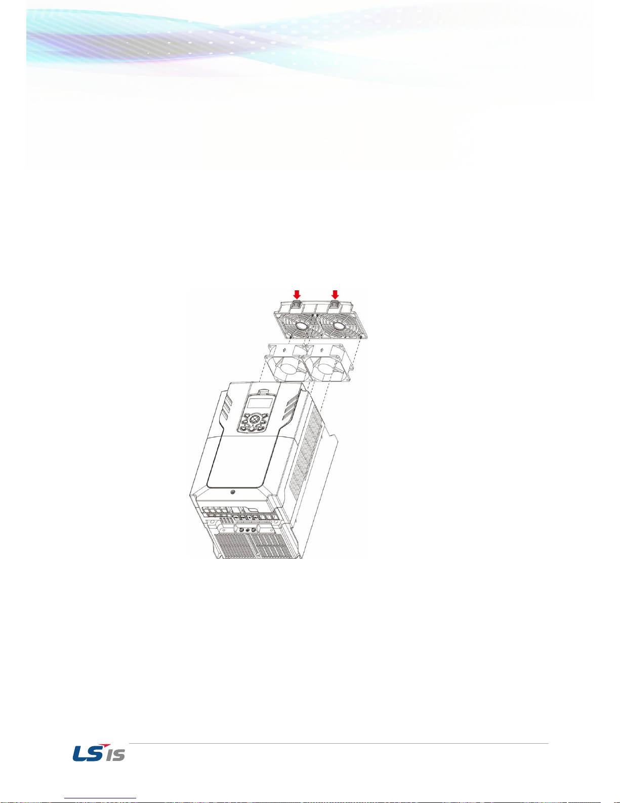
Replacement of 75~90kW FAN
1) Remove ❶ screws to separate the fan bracket from the inverter.
2) Disconnect the fan wire and remove ❷ screws.

3. Maintenance
44
Caution
Turn off the inverter before replacing the fan. There is a possibility of an electric shock due to
the charge voltage. Wait until the inverter is fully discharged to replace the fan. (The time to
discharge varies per capacity, in average 1~3 minutes after turning off the inverter).
Make sure the fan wire and connect is not touching the blades. If touched it leads to
malfunction of the inverter. Make sure the inverter is completely turned off before cleaning.
After replacing the fan, assemble the fan. Before using the inverter, turn on the inverter and
check the condition of the fan by its motion.
Be careful of the direction of the fan.
Storage and Disposal 3.2
Storage 3.2.1
Store the products in the following conditions listed below (if not used for a long period of time).
Store the product in the same appropriate environmental conditions as in operation.
If the product will be stored more than 3 months, keep the ambient temperature between -
10℃~30℃ to prevent degradation of the electrolytic capacitor.
The products should not be exposed to snow, rain, fog and dust.
When packing the inverter, include a dehumidifier (e.g. silica gel) to keep the ambient
temperature inside the package below 70% and prevent in contact with moisture.
If the products will be left in a humid or dusty environment (construction sites or control panel)
separate the products in a location that has the same appropriate environmental conditions as
in operation.
Disposal 3.2.2
Categorize the inverters as general industrial waste when disposing the product. Note that there
are recyclable raw materials in the product, such as packing materials and metalwork. For the sake
of conservation of energy and resources, recycle whenever possible. Depending on the country,
plastic may be recyclable. Please check the local environmental regulations for more details.
Caution
Capacitors lose their charging characteristics if not operated for a long time. In order to prevent
this from happening, turn on the product and allow the device to operate for 30~60 minutes once
a year. Note that operation should be conducted under no-load conditions.
 Loading...