


Right choice for ultimat e yield!
LSIS strives to maximize customer’s profit in gratitude of choosing us for your partner.
Human Machine
Interface
XGT PANEL
eXP Series
User
’s Manu al
eXP20
-TTA
eXP30
-TTA
eXP30
-TTB
eXP30
-TTE
e
XP40-TTA
eXP40
-TTB
e
XP40-TTE
eXP60
-TTA
eXP60
-TTB
Read this manual carefully before
installing,
wiring, operating, servicing
or inspecting this equipment.
Keep this manual within easy reach
for quick reference.

Safety Precautions
1
Before using the product…
To use the product safety and effectiv ely, please r ead this inst ruction manual thoroughly before us e.
► Please keep to the safety precaution, for it to prevent accidents and potential danger from
occurring.
► Safety precaution is clas sified into ‘ Warming ’ and ‘Caution’ and their meani ngs are as foll ows.
Warning Violating the instruct ion may result i n serious personal i njury or death.
Caution Violating the instruction may result in slight personal injury or product
damage.
► The indicated illustrati ons on the product an d in the manual hav e the fallow ing meanings.
Be cautions, for danger may be pr esent.
Be cautions, for there is a pos sibility of an el ectric shock.
► After reading the instruc tion manual, keep i t handy for quic k reference.
Safety Precautions
2
Design Precautions
Design Precautions
Installation Precautions
►
Install a safety circuit e xt ern al t o the H M I t o p rot ect t h e whol e con t ro l system in case of
external power supply trouble.
Serious trouble may occur to the entire system due to erroneous output/operation of the HMI.
Warning
► In/output signal or communication cable should be at least 100mm apart from High-
voltage/power wires.
Otherwise, it may cause erroneous output/operation.
► Use the HMI in an environment that meets the general specification contained in this
manual or datasheet.
Otherwise, it could result in electric shock, fire, erroneous operation or deterioration.
► In case of much vibration in the installed environment, be sure to insulate the HMI from
direct vibration.
Otherwise, it could result in electric shock, fire, erroneous operation.
► Be sure not to let foreign subst ances such as conductive d ebris inside the pro duct.
Otherwise, it could result in electric shock, fire, erroneous operation.
Caution
Caution

Safety Precautions
3
Wiring Precautions
► Be sure to turn off the HMI and external power before wiring.
Otherwise, it may result in an electric shock or damage to the product.
► Wire correctly by checkin g each of the pro duct’ s rated voltage and terminal layout.
Otherwise, it may result i n fire, electric shock or erroneous operation.
► Tighten terminal screws with specified torque when wiring.
If terminal screws are l oose, it may result i n short circui ts, fire or err oneous operation.
► Use the exclusive HMI 3-type grounding for the FG terminal.
If not grounded, it may r esult in erroneous operation.
► Be sure not to let any foreign substances such as wiring debris inside the module.
Such debris may cause fire, da mage or erroneou s operation.
Warning
Caution

Safety Precautions
4
Startup and Maintenance Precautions
Disposal Precaution
► Do not touch the terminals while power is on.
Otherwise, it may cause electric shock or erroneous operation.
► T urn off the HMI and external power when cleaning or tightening the terminal.
Otherwise, it may cause electric shock or erroneous operation.
► Do not charge, disassemble, heat , short circui t, solder , etc. other batt ery.
Mishandling the battery may cause overheating, crack, fire and may result in injury or fire.
► Do not disassemble PCB from the product case or modify the product.
Otherwise, it may result in fire, electric shock or erroneous operation.
► Use cellular phone or walky-talky at least 30c m away from the HM I.
Otherwise, it may result in erroneous operation.
► When disposing of this product or battery, treat it as industrial waste.
Otherwise, it may cause poisonous pollution or explosion.
Warning
Caution
Caution

Revision History
5
Revision History
Version Date Contents Revised location
V1.0
‘16.05
First Edition
-
V1.1
’16.07
Additional model (eXP20-TTA)
1-2,2-1~2,3-3,10-3~6,App2-1
V1.2
’17.08
Additional model (eXP30-TTA/TTE)
2-3~4,3-2,11-3~5,App2-2
V1.3
’18.05
eXP30-TTA general standard revision
3-1

※ The number of User’s manual is indicated the right side of the back cover.
ⓒ LSIS Co., Ltd 2016 All Rights Reserved.


Contents
6
Chapter 1 General Introduction ...................................................................... 1-1~1-6
1.1 How to use the Instruction Manual ........................................................................................................ 1-1
1.2 Feature .................................................................................................................................................. 1-2
1.3 Terminology........................................................................................................................................... 1-6
Chapter 2 System Configuration ....................................................................... 2-1~2-6
2.1 Part Names ........................................................................................................................................... 2-1
2.2 System Configuration ............................................................................................................................ 2-5
Chapter 3 Standard Specification .................................................................... 3-1~3-4
3.1 General Standards ................................................................................................................................ 3-1
3.2 Function Standards ............................................................................................................................... 3-3
Chapter 4 System Configuration ................................................................... 4-1~4-13
4.1 Backlight Setting ................................................................................................................................... 4-2
4.2 Touch Calibration .................................................................................................................................. 4-3
4.3 Date Time Setting ................................................................................................................................. 4-4
4.4 Environment Setting .............................................................................................................................. 4-5
4.5 Ethernet Setting .................................................................................................................................. 4-11
4.6 XP-Remote Setting ............................................................................................................................. 4-12
4.7 Buzzer Setting ..................................................................................................................................... 4-13
Chapter 5 Diagnostics ...................................................................................... 5-1~5-8
5.1 Screen Diagnosis .................................................................................................................................. 5-2
5.2 Touch Diagnosis ................................................................................................................................... 5-3
5.3 Backup Memory Diagnosis ................................................................................................................... 5-4
5.4 Flash Memory Diagnosis ....................................................................................................................... 5-5
5.5 USB Memory Diagnosis ........................................................................................................................ 5-6
5.6 Serial Communication Diagnos is .......................................................................................................... 5-7

Contents
7
Chapter 6 Viewing Information of PLC Connection Status .......................... 6-1~6-8
6.1 PLC Communication Configuration Settings ......................................................................................... 6-2
6.2 Connection Information ......................................................................................................................... 6-3
6.3 PLC Information .................................................................................................................................... 6-4
6.4 History of PLC Error ............................................................................................................................ 6-4
6.5 History of PLC Mode Conversion ........................................................................................................ 6-5
6.6 History of PLC Power .......................................................................................................................... 6-5
6.7 History of PLC System ........................................................................................................................ 6-6
6.8 N:1 Settings ......................................................................................................................................... 6-7
6.9 Program Monitor .................................................................................................................................. 6-8
Chapter 7 Storage Function ............................................................................. 7-1~7-4
7.1 General Introduction ............................................................................................................................ 7-1
7.2 Downloading Project thr ough the Storage Equipment .......................................................................... 7-2
7.3 Uploading Project through the Storage Equipment............................................................................... 7-3
7.4 Updating the Device through Storage Equipment................................................................................. 7-4
Chapter 8 XGT Panel S/W Update ........................................................................... 8-1
8.1 General Introduction ............................................................................................................................ 8-1
Chapter 9 File Backup through External Storage Equipment ....................... 9-1~9-7
9.1 Path Structure in case of File Backup ................................................................................................... 9-1
9.2 Operation setting when there is no space for backup ........................................................................... 9-5
9.3 Structure of path of video file and video capture files ........................................................................... 9-6

Contents
8
Chapter 10 Installation and Wiring ............................................................ 10-1~10-10
10.1 Installation ......................................................................................................................................... 10-1
10.1.1 Installation environment ........................................................................................................... 10-1
10.1.2 Notice in handling .................................................................................................................... 10-3
10.1.3 Notice in installing the panel .................................................................................................... 10-3
10.2 Wiring ................................................................................................................................................ 10-7
10.2.1 Power wiring ............................................................................................................................ 10-7
10.2.2 Ground wiring ........................................................................................................................ 10-10
Chapter 11 Maintenance ............................................................................... 11-1~11-3
11.1 Maintenance ...................................................................................................................................... 11-1
11.2 Daily Maintenance ............................................................................................................................. 11-1
11.3 Periodical Maintenance ..................................................................................................................... 11-2
Chapter. 12 EMC Standard Certification .................................................... 12-1~12-2
12.1 Requirement for EMC Standard Certification .................................................................................. 12-1
12.1.1 CE standard certification ........................................................................................................ 12-1
12.1.2 KC standard certification ........................................................................................................ 12-2
12.2 Requirement for Low Voltage Command Suitability ......................................................................... 12-2
12.2.1 Standard certification for XGT Panel ....................................................................................... 12-2
12.2.2 Selection of XGT Panel ......................................................................................................... 12-2
Appendix 1 Troubleshooting ............................................................ App1-1~App1-24
1. Type of Problem .............................................................................................................................. App 1-1
2. Problem when Starting .................................................................................................................... App 1-2
3. Problem after the Monitor on ........................................................................................................... App 1-4
4. Display Problem of Figure and Object ............................................................................................ App 1-6
5. Communication Problem ................................................................................................................. App 1-9
6. USB Removal of Memory Card ..................................................................................................... App 1-10
7. Error Message during Execution of Program ................................................................................ App 1-11
Appendix 2 Dimension .................................................................... App 2-1~ App 2-3
Appendix 3 Warranty and Environmental Policy ........................................... App 3-1

Chapter 1 General Introduction
1-1
Chapter 1 General Introduction
1.1 How to use the Instruction Manual
This instruction manual provides information such as specification, how to use, etc., of the product needed to operate eXP
series of XGT Panel.
The user manual’s configuration is as follows.
Sequence Category Contents
Chapter1 General Introduction It describes this manual’s configuration, product’s feature and term.
Chapter2 System Configuration It describes feature and system configuration of each XGT Panel.
Chapter3 Standard Specification It describes XGT Panel’s general and function specification.
Chapter4 System Configuration It describes XGT Panel’s system configuration.
Chapter5 Diagnostics It describes XGT Panel’s self-diagnosis.
Chapter6
Viewing information of
PLC Connection Status
It describes the way on connection status information of PLC which is
connected with XGT Panel.
Chapter7
Transmission of Project
from USB Storage
Device
It describes the way to execute the project by using USB storage
device.
Chapter8 XGT Panel S/W Update It describes the way to update engine at XGT Panel.
Chapter9
Backup files by using
Storage Devices
It describes the way to backup recipe, logging and etc. files by using
storage devices.
Chapter10 Installation and Wiring
It describes an installation, wiring and caution for reliability of PLC
system.
Chapter11 Maintenance
It describes inspection category and method for long normal operation
of PLC system.
Chapter12 EMC Standard It describes system configuration for EMC standard.
Appendix 1 Troubleshooting It describes a variety of error contents and measure.
Appendix 2 Dimension It describes the dimension of XGT Panel.
Appendix 3
Warranty and
Environment Policy
-
Remark
This manual doesn’t describe connection with XP-Builder and PLC. For their own function, Please refer to the related
manuals.

Chapter 1 General Introduction
1-2
1.2 Feature
XGT Panel series has the following features.
(1) Various types of external interface
(a) Supporting var ious device of USB, Ethernet, it maximizes the customer’s usability.
Various communicat ion connectors are plac ed at the l ower side s o that it c an be connected in a variet y
of types with the contr ol device such as PLC, invert er, etc. Through RS-485, RS-232C, RS-422/485,
Ethernet (10Base-T /100Base-TX) communication, it can be connected with control device.
Status LED
- When power on,
USB DEVICE(eXP30/40/60)
- Project download through
XP-Builder
Battery Cover
- Reset Switch
- Battery,
- Setting Switch,
RS-422/485(eXP40/60)
- Control device that can be communicated such as PLC
USB HOST
- Data Backup
(alarm, logging, recipe, etc.)
- Project data storage
(image, upload project, etc.)
- Mouse, Keyboard,
RS-485(eXP40/60)
RS-422/485(eXP20/30)
- Control device that can be
communicated such as PLC
Ethernet
- Project downloads through XP-Builder
- Control device that can be communicated
such as PLC
-
Connected with fieldbus and open
network
Power Terminal
- Composed of power
input and PE terminal
RS-232C
- Control device that can
be communicated such as
PLC

Chapter 1 General Introduction
1-3
(2) Based on Windows CE
(a) Adoption of Microsoft Company’s Windows CE
• Windows CE 6.0
(b) Advantage
• It provides stable software capacity by using Microsoft Company’s platform.
• It can process diverse function simultaneously.
• It provides diverse interface including Ethernet, USB.
• The user interface including mouse and keyboard can be connected.
• It has high flexibility like computer software.
• Fast reaction is available when adding new equipment.
• Wide data sharing and management with upper system is available (Later).
(3) Improvement of project transmission time
(a) It provides Ethernet which is faster than RS-232C.
(b) It provides the transmission function from USB storage device.
(4) High quality screen
(a) It provides the high quality screen and clearness by high quality LCD.
• It adopts TFT LCD which supports the 65,536 Color.
(b) It provides diverse graphic type.
• It is available to express precisely and actually.
• It provides the simple moving function with GIF support.
Chapter 1 General Introduction
1-4
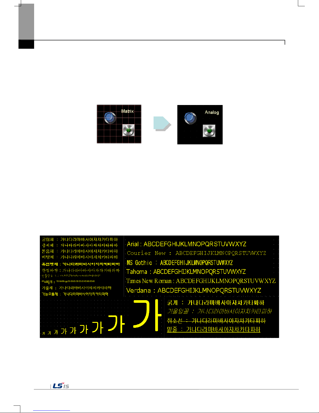
(5) Analog touch Panel
(a) It adopts analog (resistive) Touch Panel.
• Visibility is improved without the grids .
(b) It provides high touch resolution.
• It can control Touch Panel precisely.
(6) Multilingual and diverse font
(a) It supports the multilingual function.
• It transmits the Windows/User font used in computer to XGT Panel.
• Additional language development is not necessary.
• Multilingual language is an advantage of Windows CE.
(b) It can express twelve kinds of language simultaneously.
• It can express 12 kinds of language simultaneously.
• Language switching is available by using special switch during operation.
(c) It can provide the various fonts.
• Various expressions are available by using the Windows/User font.
• Font size and type can be adjusted freely.

Chapter 1 General Introduction
1-5
(7) Advanced function
(a) Alarm function.
• T he History alarm c an be classified alarm group and alarm list and se lected alarm can be expressed
by alarm search.
• The Flow alarm indicates current or the latest alarm at the bottom of screen.
• The System alarm indicates the important problems from operation.
(b) Logging function
• It pr ovides conditional logging accordin g to device condition and continuo us periodic loggi ng which
operates periodically according to time and device status.
• It provides 256Kbyte areas for backup.
• Backup into USB storage device is available.
• Backup data’s type is stored in Excel, it is easy to use.
(c) Recipe function.
• It provides READ/WRITE function.
• It provides 128Kbyte areas for backups.
[General recipe: it set up 10,000 double words for each of one of them.]
• Backup into the USB storage device is available.
• Backup data’s type is stored in Excel, it is easy to use.
(d) Scheduler function.
• It can be set up to Max. 32.
(e) Print function.
• It provides a Screen/Alarm print function.
• It can be printed by USB printer.
(f) Script function.
• It provides more flexible function by user Script.
• It can be diversely applied to such as including Glob al/O bj ect/Screen indication and so on.
(8) Stable product suitable for international standards
(a) CE, KC standard acqu isit io n
(b) UL(cUL) standard acquisition
(c) NEMA standard acquisition (UL Type 4X)
- Only for eXP20-TTA/DC,CERTI

Chapter 1 General Introduction
1-6
1.3 Terminology
It describes terms used in this manual.
Term Definition Remarks
Module
A standard element that has a specified function which configures the
system.
Devices such as I/O board, which inserted onto the mother board or
base unit..
Ex) CPU module,
Power Module,
I/O module
Unit
A single module or group of modules that perform an independent
operation as a part of PLC system.
Ex) Basic unit,
Extension unit
PLC system
System consisted of PLC and peripheral device which can be
controlled by user program.
-
XP-Builder
Software used to write and edit the project.
-
XP-Manager
It is the software for edition, download, monitoring to realize data
communication between XGT Panels through XP Link with online
control function.
XP-Remote
Software used to remote monitor and control the XGT Panel
Cnet module
Computer Link
-
FEnet module
Fast Ethernet Network
-
RTC
Abbreviation of ‘Real Time Clock’.
It is used to call general IC that contains clock function.
-
1.4 Standard of product name
It describes terms used in this product names.
Term Sign Contents Remark
(A) LCD Size
20
10.9cm (4.3”)
30
14.2cm (5.6”)
40
17.8cm (7”)
60
25.9cm (10.2”)
(B) LCD type
T
TFT Color
(D) Product type
A
Advance
Normal
B
Pro plus
Premium
(E) Power type
AC
AC SMPS
AC100-240V
DC
DC SMPS
DC24V
eXP
(A)
(B)
(C)
(D)
(E)

Chapter 2 System Configuration
2-1
Chapter 2 System Configuration
Characteristic of each eXP series and its system configuration are as follow;
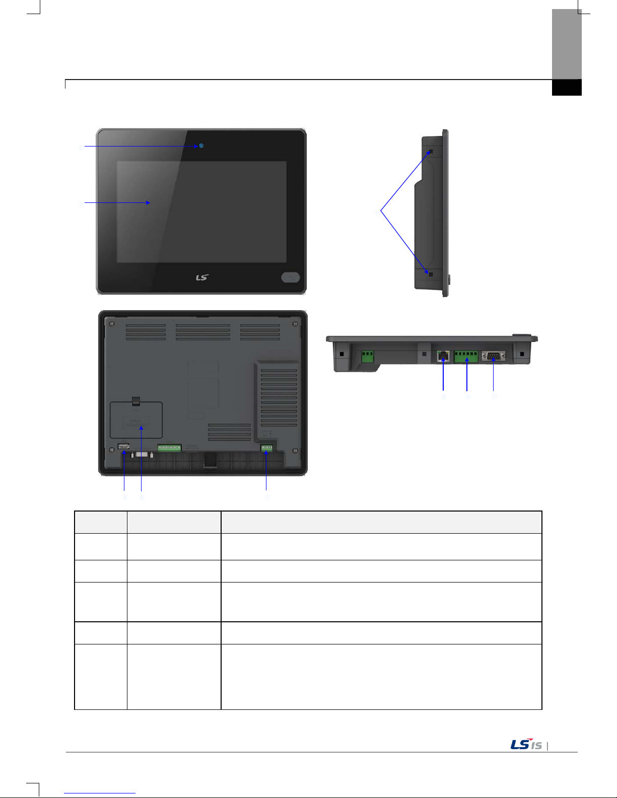
2.1 Part Names
1. eXP20-TTA/DC, eXP20-TTA/DC,CERTI
①
③
②
④
⑤
⑥
⑦
⑧
Items Part Names
Descriptions
① Front Part
1) Analog Touch Panel: Input by user’s touch
2) LCD: Screen indication
② Po wer LED
Indicating the state of device (On: BLUE)
※ High Luminance Blue LED
③
Panel Mounting
Panel
Fixing XGT Panel on the panel using bracket

Chapter 2 System Configuration
2-2
Items Part Names
Descriptions
④ Power Terminal Composed of Power Input(DC24V) and PE Terminal
⑤ USB Interface
1) USB Memory Connection: Backup of data such as alarm/logging/recipe
and
storage of screen data
2) USB Memory Connection: Send/Receive project data, Send XP-Runtime
3) User’s Interface Connection: Using mouse/keyboard
4) Printer connection: Printing function
⑥
Battery Cover
Reset Switch
Backup Battery
Setting Switch
<Setting Switch>
No.1
A Side. Backup Battery On
B Side. Backup Battery Off
No.2 / 3
A Side. RS-422/485 Terminating Resistance On
B Side. RS-422/485 Terminating Resistance Off
No. 4
A Side. O/S Download Mode
B Side. Operating Mode
⑦ Ethernet Terminal
Ethernet: 10Base-T/ 100Base-TX
1) Send Project Data
2) Receive backup data and project file
3) Send XP-Runtime
4) PLC/Control Device Communication
⑧
RS-232C, RS422/485 Connector
RS-232C (COM2): PLC/ Control Device Communication
RS-422/485 (COM3): PLC/ Control Device Communication
※
COM1 is not used.

Chapter 2 System Configuration
2-3
2. eXP30-TTA(B)/DC, eXP30-TTE/DC
①
③
②
⑤ ⑥
⑦
⑧
④
⑨
Items Part Names
Descriptions
① Front Part
1) Analog Touch Panel: Input by user’s touch
2) LCD: Screen indication
② Po wer LED
Indicating the state of device (On: BLUE)
※ High Luminance Blue LED
③ USB Device
1) Logging/Recipe/Scree n Data Bac kup
2) Send project data and XP-Run time
3) Receive back data and project file
④
Panel Mounting
Panel
Fixing XGT Panel on the panel using bracket
⑤ Power Terminal Composed of Power Input(DC24V) and PE Terminal

Chapter 2 System Configuration
2-4
Items Part Names
Descriptions
⑥ USB Interface
1) USB Memory Connection: Backup of data such as alarm/logging/recipe
and storage of screen data
2) USB Memory Connection: Send/Receive project data, Send XP-Runtime
3) User’s Interface Connection: Using mouse/keyboard
4) Printer connection: Printing function
⑦
Battery Cover
Reset Switch
Backup Battery
Setting Switch
<Setting Switch>
No.1
A Side. Backup Battery On
B Side. Backup Battery Off
No.2 / 3
A Side. RS-422/485 Terminating Resistance On
B Side. RS-422/485 Terminating Resistance Off
No. 4
A Side. O/S Download Mode
B Side. Operating Mod e
⑧ Ethernet Terminal
Ethernet: 10Base-T/ 100Base-TX
1) Send Project Data
2) Receive backup data and project file
3) Send XP-Runtime
4) PLC/Control Device Communication
⑨
RS-232C, RS422/485 Connector
RS-232C (COM2): PLC/ Control Device Communication
RS-422/485 (COM3): PLC/ Control Device Communication
※
COM1 is not used.

Chapter 2 System Configuration
2-5
3. eXP40-TTA(B)/DC, eXP40-TTE/DC
②
①
⑤ ⑥ ⑦
⑧
⑨
⑩
④
Items Items Items
①
Front Part
1) Analog Touch Panel: Input by user’s touch
2) LCD: Screen indication
②
Power status LED Indicating the state of device (On: BLUE)
③
USB Device
1) Logging/Recipe/Scree n Data Bac kup
2) Send project data and XP-Run time
3) Receive back data and project file
④
Panel Mounting Part Fixing XGT Panel on the panel using bracket
⑤
USB Host
1) USB Memory Connection: Backup of data such as alarm/logging/recipe
and storage of screen data, Send/Receive project data, Send XP-Runtime
2) User’s Interface Connection: Using mouse/keyboard
3) Printer connection: Printing function
* Rated 5 VDC, Typical 100mA

Chapter 2 System Configuration
2-6
Items Items Items
⑥
Battery Cover
<Setting Switch Configuration >
NO.1
A Side.
Backup Battery ON
B Side.
Backup Battery OFF
NO.2
A Side.
Do not use
B Side.
Do not use
NO.3
A Side.
COM1 RS-485 Terminating Resistance On
B Side.
COM1 RS-485 Terminating Resistance Off
NO.4
A Side.
COM3 RS-422 Terminating Resistance On
B Side.
COM3 RS-422 Terminating Resistance Off
NO.5
A Side.
O/S Download Mode
B Side.
Operating Mode
⑦
Power Terminal Composed of Power Input(DC24V) and FG Terminal
⑧
Ethernet Terminal
Ethernet: 10Base-T/ 100Base-TX
1) Send Project Data
2) Receive backup data and project file
3) Send XP-Runtime
4) PLC/Control Device Communication
⑨
COM3 Connector RS-422/485: PLC or Control Device Communication
⑩
COM1, COM2
Connector
RS-485, RS-232C: PLC or Control Device Communication
Remark
(1) For further details on connection of communication, please refer to Communication Instruction Manual.
(2) For further details on installation, please refer to the Chapter 10.
A. Reset Switch
B. Coin Battery
C. Setting Switch
Chapter 2 System Configuration
2-7
4. eXP60-TTA(B)/DC
①
②
⑤
⑥
⑦
④
⑧
⑨
⑩
Items Items Items
①
Front Part
1) Analog Touch Panel: Input by user’s touch
2) LCD: Screen indication
②
Power status LED Indicating the state of device (On: BLUE)
③
USB Device
1) Logging/Recipe/Scree n Data Bac kup
2) Send project data and XP-Run time
3) Receive back data and project file
④
Panel Mounting Part Fixing XGT Panel on the panel using bracket
⑤
USB Host
1) USB Memory Connection: Backup of data such as alarm/logging/recipe
and storage of screen data, Send/Receive project data, Send XP-Runtime
2) User’s Interface Connection: Using mouse/keyboard
3) Printer connection: Printing function
* Rated 5 VDC, Typical 100mA

Chapter 2 System Configuration
2-8
Items Items Items
⑥
Battery Cover
<Setting Switch Configuration >
NO.1
A Side.
Backup Battery ON
B Side.
Backup Battery OFF
NO.2
A Side.
Do not use
B Side.
Do not use
NO.3
A Side.
COM1 RS-485 Terminating Resistance On
B Side.
COM1 RS-485 Terminating Resistance Off
NO.4
A Side.
COM3 RS-422 Terminating Resistance On
B Side.
COM3 RS-422 Terminating Resistance Off
NO.5
A Side.
O/S Download Mode
B Side.
Operating Mode
⑦
Power Terminal Composed of Power Input(DC24V) and FG Terminal
⑧
Ethernet Terminal
Ethernet: 10Base-T/ 100Base-TX
1) Send Project Data
2) Receive backup data and project file
3) Send XP-Runtime
4) PLC/Control Device Communication
⑨
COM3 Connector RS-422/485: PLC or Control Device Communication
⑩
COM1, COM2
Connector
RS-485, RS-232C: PLC or Control Device Communication
Remark
(1) For further details on connection of communication, please refer to Communication Instruction Manual.
(2) For further details on installation, please refer to the Chapter 10.
A. Reset Switch
B. Coin Battery
C. Setting Switch

Chapter 2 System Configuration
2-9
2.2 System Configuration
In order to use XGT Panel, it is necessary for XP-Builder to prepare project data and transmit it to XGT Panel.
Normally you can connect with XGT Panel using RS-232C.
Maximum Communication speed is 115,200[bps].
With Ethernet in use, you can transfer project data more quickly.
With LAN environment built in the following configuration, you may use it more easily and effectively
1:1 connection will be supported just in case LAN environment is not built.
Chapter 2 System Configuration
2-
If it is impossible to transfer project data using Communication, you can use USB storage device.
For how to use in details, please see the Chapter 7 and XP-Builder User’s Manual.
Remark
(1) Recommend to transfer project by using Ethernet than RS-232C.
(2) For how to make Ethernet cable, please see the Communication User’s Manual.
(3) For how to transfer project, please see XP-Builder User’s Manual.
(4) eXP30-TTE/DC and eXP40-TTE/DC are not support Ethernet.
Chapter 3 Standard Sp ec ification
3-1
Chapter 3 Standard Specification
3.1 General Standards
XGT Panel general standard is as follows.
No.
Category
Standard
Related standard
1
Ambient operating
temperature
0℃∼+50℃
-
2 Storage temperature
-20℃∼+60℃
-
3
Operating humidity
10∼85%RH, non-condensing.
-
4 Storage humidity
10∼85%RH, non-condensing.
-
5 Vibration resistance
Occasional vibration
count
-
Frequency Acceleration Amplitude
10 times each in X, Y
and Z direction
IEC 61131-2
5≤f<
Hz -
3.5mm
9≤f≤150
Hz
9.8
m/s2 -
Continuous vibration
Frequency
Acceleration
Amplitude
5≤f< 9
Hz
- 1.75mm
9≤f≤150
Hz
4.9
m/s2
-
6 Shock endurance
* Maximum shock acceleration: 147
m/s2 (15G)
* Duration time: 11ms
* Pulse wave: half sine pulse (3 times each in X, Y and Z directions)
IEC 61131-2
7
Noise
Immunity
Square wave
Impulse noise
DC: ±1,200V LSIS Standard
Electrostatic Discharge
Immunity
±6 kV(Contact Discharge),
±8 kV(Air Discharge)
IEC 61131-2
IEC 61000-4-2
Electromagnetic
Radiated Emissions
80 ~ 1,000 MHz, 10 V/m
IEC 61131-2
IEC 61000-4-3
Electrical Fast
Transient & Burst
Immunity
Category Power module
Communication
Interface
IEC 61131-2
IEC 61000-4-4
Voltage 2.4 kV 1.2 kV
8 Environment Free from corrosive gases and excessive dust -
9
Operating height
Up to 2,000m(6,562ft)
-
10 Pollution degree 2 or less -
11
Cooling method
Natural Air-Cooling
-

Chapter 3 Standard Sp ec ification
3-2
Remark
(1) IEC(International Electro technical Commission)
- International private group facilitating international cooperation of electric/electronic standardization,
issuing international standards and operating the compliance evaluation systems.
(2) Pollution degree
- As an index represe nting the pollution degr ee of an environm ent to determine the insulati on of a device,
pollution degree 2 gen erally means the status g enerating non-conductiv e contamination. However, it also
contains the status generating temporarily conduction due to condensation.
(3) Definition of Overvoltage Categories
- Equipment of overvoltage category II is energy-consuming equipment to be
supplied from the fixed
installation.
- Examples of such equipment are appliances, portable tools and other household and similar loads.

Chapter 3 Standard Sp ec ification
3-3
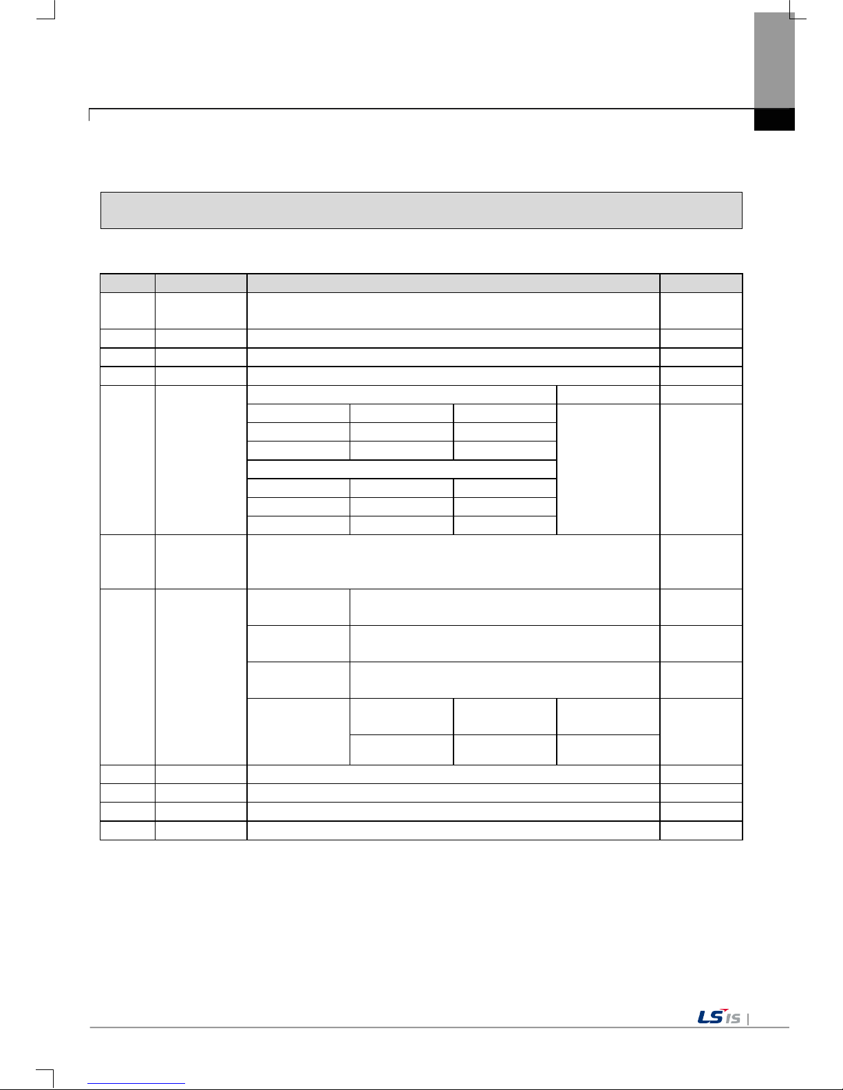
3.2 Function Standards
eXP Series function standard is as follows.
Item
eXP20-TTA/DC,CERTI
eXP20-TTA/DC eXP30-TTA(B)/DC eXP30-TTE/DC
Display type
TFT color LCD
Screen size 10.9cm(4.3”) 14.2cm(5.6”)
Display Resolution 480 x 272 640 x 480 pixel
Color indication
24-bit Color(16.7M) 16-bit Color(65,535 Color)
Indication degree
Left/Right:60 deg.
Upper:40 deg.
Lower:60 deg.
Backlight
LED Type (Supports backlight auto-off function)
Backlight duration
30,000 hours 20,000 hours
Touch panel
4-Wire Resistive, analog
Audio Output Magnetic buzzer (85dB)
Process
i.MX283(454MHz)
Memory
Flash 128MB (Screen 64MB)
Operating RAM
128KB
Backup RAM 128KB
Backup data Date/Hour data, Logging/Alarm/Rec ipe data and nonvolatile device
Battery duration Approx. 3 years (Operating ambient temperature of 50℃)
RTC Time error Approx. 3 sec/1day(Operating ambient temperature of 25℃)
Ethernet
1 channel, IEEE802.1a, 10Base-T/100Base-TX
-
USB Host 1 channel, USB 2.0 Host (mouse, keyboard, printer and USB memory driver is available)
USB Device
- 1 channel, USB 2.0 Device
(for download and upload project)
RS-485, RS-232C
1channel, RS-232C
(DSUB 9/Male Type)
RS-422/485
1channel, RS-422/485
(DSUB 9/Male Type)
Multi-language Up to 12 language simultaneously
Animation
GIF format is available
Recipe available
Data logging
available
Script executor available
Certifications
CE, UL Type4X, KC
CE, UL(cUL), KC
Protection standard IP66 IP65
Dimension (mm)
128x102x32
300 x 200 x 68
Panel cut (mm) 119.0x93.0 156.0 x 123.5
Rated voltage
DC24V
Power consumption (W) 4.6W 7.2W
Weight(Kg)
0.3
0.42
0.39

Chapter 3 Standard Sp ec ification
3-4
Item
eXP40-TTE/DC
eXP40-TTA(B)/DC eXP60-TTA(B)/DC
Display type
TFT color LCD
Screen size
17.8cm(7”)
25.9 cm(10.2”)
Display Resolution 800 x 600 pixel(WVGA)
Color indication
24-bit Color(16.7M) 16-bit Color(65,536)
Indication degree
Left/Right:60 deg.
Upper:40 deg.
Lower:60 deg.
Left/Right:55 deg.
Upper:35 deg.
Lower:55 deg.
Backlight
LED Type (Supports backlight auto-off function)
Backlight duration
20,000 hours
Touch panel
4-Wire Resistive, analog
Audio Output Magnetic buzzer (85dB)
Process
i.MX283(454MHz)
Memory
Flash 128MB
Operating RAM
128MB
Backup RAM 128KB
Backup data Date/Hour data, Logging/Alarm/Recipe data and nonvolatile device
Battery duration Approx. 3 years (Operating ambient temperature of 50℃)
RTC Time error Approx. 3 sec/1day(Operating ambient temperature of 25℃)
Ethernet
-
1 channel, IEEE802.1a, 10Base-T/100Base-TX
USB Host 1 channel, USB 2.0 Host (mouse, keyboard, printer and USB memory driver is available)
USB Device
1 channel, USB 2.0 Device (for download and upload project file)
RS-485, RS-232C 2channels, RS-485, RS-232C (DSUB 9/Male Type)
RS-422/485
1channel, RS422/485 mode (Terminal Type)
Multi-language Up to 12 language simultaneously
Animation
GIF format is available
Recipe available
Data logging
available
Script executor available
Certifications
CE, UL(cUL), KC
Protection standard IP65
Dimension (mm) 208.0 x 154.0 x 44.4 276.0 x 218.0 x 44.4
Panel cut (mm) 192.0 x 138.0 260.0 x 202.0
Rated voltage
DC24V
Power consumption (W) 6.5W 10W
Weight(Kg)
0.62
0.63
1.08

Chapter 3 Standard Sp ec ification
3-5
Note
(1) Caution in power connection
: With AC power applied to DC power device, it may cause product damage or fire.
Please pay a special attention to connection.
(2) PE Connection
: For the device PE, please use ⑦ PE terminal in the Chapter 2.1.
(3) Battery discharge-prevention DIP switch
: In order to prevent the battery discharge, turn off the DIP switch No.1.
To use backup function, please turn on DIP switch No. 1.
(4) Battery Operation and Life
: Battery is used for RTC (date/time) when the power of device is off.
Battery is not consumed with power applied.
(5) LCD Backlight Replacement
: Please replace LCD if you want to replace LCD backlight.
(6) Protection standard
: XGT Panel is designed by IP65 Standard in front p ar t s . Ingres s Protec t ion (IP) is based on the IEC 605 29
Standard for degrees of protection provided by enclosures. But XGT Panel does not guarant ee from all
installation environm ent. W hen instal ling pane ls, m ak e sure that dust an d m oisture are not br ought in. For
more details on installation, See Chapter 10.installation and Wiring.


Chapter 4 System Configuration
4-1
Chapter 4 System Configuration
It describes the system configuration including XGT Panel’s time setting, Ethernet connection setting, and
Backlight settings.
If you press [Settings] button in XGT Panel’s Main screen, you can set XGT Panel’s environment as follows.
☜
[XGT Panel main screen]
[System Configurati on screen ]

Chapter 4 System Configuration
4-2
4.1 Backlight Setting
If you press [Backlight Setting] button in [System Configuration] screen as follows, setting screen shows up.
[XGT Panel setting screen]
[Backlight setting screen]
[Dialog box setting option]
Name Description
Brightness
It may adjust brightness of backlight.
Do not turn off backlight
It doesn’t turn off backlight power.
Turn off backlight after idle time
It automatically turns of f backlight if not in touch for a certain period of
time.
Turn off ~ minutes
It turns off backlight after a designated time (unit of minute).

Chapter 4 System Configuration
4-3
4.2 Touch Calibration
When the location is not recognized in XGT Panel, Touch’s scale can be adjusted in XGT Panel. If you press
[Touch Calibration] button in System Configuration, the setting screen shows up. If you press five ‘+’ marks, XGT
Panel’s touch location adjustment is completed.
[XGT Panel setting screen]
[Touch setting screen]
Remark
(1) XGT Panel’s Touch Calibration setting is basically set. If Touch location is way off, adjusting menu with
touch can be hard through touch. In that case, You can select the Touch Calibration setting menu by
USB mouse or simply touch
5 times at the empty space on the main screen.
(2) When touch location changes in using, redo touch setting.

Chapter 4 System Configuration
4-4
4.3 Date Time Setting
If you press [DateTime Setting] button in [System Configuration] as follows, you can set XGT Panel’s data and
time.
Remark
You can set data/time at device information of communication dialog at the XP-Builder.
For details, please refer to the XP-Builder’s manual.

Chapter 4 System Configuration
4-5
4.4 Environment Setting
If you press [Environment Setting] button in [System Configuration] screen as follows, you can set ‘Auto Goto
Screen’ and ‘Buzzer On/Off’.
[XGT Panel setting]
[Environment - screen]

Chapter 4 System Configuration
4-6
[Environment - General]
[Environment - General]
[Environment setting screen]

Chapter 4 System Configuration
4-7
[Dialog box]
Name
Description
Go to screen after boot up
When setting [Auto Got o Scr een], XGT Panel is reb ooted. Or when d own loading
the edit data is c ompleted , the scr een autom aticall y sho ws up. If you cance l this
setting, the user should press ‘Start’ button in order to move to the screen.
Quick start
When starting screen, screen shows promptly without showing progress bar
because it doesn’t caching the image in advance. However, if you select this
option, first screen s ho ws s lowl y. Especially, if ther e ar e m an y animatio n obj ects
in screen, it may take several seconds based on image. But fast screen
switching is available since second screen switching.
Show progress
on the bottom
If XGT Panel start monitoring by touch in g th e [ Start ] o n th e main screen, and th e
buffering images used in your project. You will see the progress of the job. (If
you do not show the quick start setup.). In this case, if the [Show progress on the
bottom] check box is checked while this progress is displa yed at the bottom of
the screen to a m ore sim plified s tate. If you us ed the d efault scr een bac kground
image, you can try to apply this option.
Show always title bar
of popup window
It indicates title bar on pop up window. W ith title bar of pop up windo w selected,
it may move the location.
Do not show menu bar
The menu bar basica lly provided to go out f rom monitoring s creen to the waiting
screen doesn’t sho w. In this case, if you want to go out t o the waiting screen,
you have to use the special switch to close the monitoring screen.
Enable Arabic text
display(right -> lef t)
It enables the language indicated from right to left directions.
Set startup screen
The screen that corr es po nd s to t he number entered at the s tart of the monitoring
is displayed first.
Hide mouse cursor
After the screen has been moved to another page, the mous e cursor does not
appear.
Buzzer On/Off
You can set whether you use buzzer through [Buzzer On/Off] button.
Buzzer Test
It may test the buzzer.
Reset USB Power
after boot up
When XGT Panel starts , USB power state is con verted f rom Off to On initia lizing
the connected device.
Low Memory Mode
XGT Panel screen to i ncreas e the operat ing speed, will use the images used on
the screen prior to the start of monitoring in advance, and then loaded into
memory. However, if t he image of a ver y large amount of proj ects used, due to
the memory space constraints will not be able to load all the images before
monitoring begins. In th is case, when the switching scr een is performed, it will
take time for loading im ages and retrieving t o search the mem ory and to delete
them that had not loa ded at the beginni ng of the part. This kind of proces s may
XGT Panel make slow.
In this situation, we recom mend that you use a "Low Mem ory Mode" by selecting
on the “Not use of image cash”. if you use "Low Memory Mode" rather than
loading the image pri or to monitoring, it requires less mem ory by reducing time
for the loading the original images into the memory and deleting them in the
project. Consequently the performance can be improved.

Chapter 4 System Configuration
4-8
Clear SRAM memory and
data files
All files downloaded by the user are deleted. If connec tion password is set, you
have to input t he password. This pass word is connection pass word needed for
project download, etc.
You can set that p assword in [Communication] [XGT Panel Information]
[Password] tap.
The deleted files are user p rojec t file, web s erver, VNC s tart module, o pti on card
driver, RAPIEnet com munication set ting data, XP-manager setting data and etc.
Setting through Environment Setting menu of device is not initialized. If the menu
is not in English, it is necess ary to reboot device to delete the m ulti lingua l r elated
files.
Set Background Image
If you select the image through [Set Background Image], background image of
waiting screen is set as the selected image. If you want to cancel, press [Delete
Background Image]
[Background Image Selection Screen]
[Use boot image] With an option selected, you cannot use it unless it is the
image of different resolution from that of XGT Panel or 24-bit image.

Chapter 4 System Configuration
4-9
Printer Settings
If there is no printer information displays the following message and must be
downloaded from the XP-Builder. You can prepare your download, then go to
the Start menu in XP-Runt ime and use the m enu after using the pr inter settings
from XP-Builder.
<Printer driver and Information None Download Required>
<The printer driver is ready to use>

Chapter 4 System Configuration
4-10
Printer Settings
(Dialog)
Name
Description
Port
Displays the connection type.
Printer type
Displays the type of printer.
Print direction
Sets whether horizontal or vertical.
Print color
Sets whether color or black and white.
High quality print
Specifies whether the advanced printing.
More...
More Properties: Disp la ys add itional pr opert ies. If you
change the additional printer properties, check the
information in the dialog. After that, press the OK
button to save settings.
OK
To save the settings.
Cancel
To cancel the setting.
Printer Check To diagnose the con nectio n status of the pr inter. T his
feature is only supp orted Sewoo pri nter (LK-P30, LKP41, LK-P43). Press t he button to disp lay the current
printer status. Please m ount again the pr inter cable if
the printer is already powered with the cable
connected.
*Messages*
1. OK: Normal state
2. No Printer: Not connected to the printer
3. Cover Open: Paper cover is open
4. Paper Empty: Out of paper
Test Page This function is designed to te
st the print output
status. Outputs the fol lowing inf orm ation, an d it brief l y
shows the current print stat.
***********************************
Test page
***********************************
DateTime: 2014-02-04 10:00:00
XP-Runtime version: 1320
Printer driver version: 1.00
Printer name: PCL3 LaserJet
Port: USB
***********************************

Chapter 4 System Configuration
4-11
4.5 Ethernet Setting
If you press [Ethernet Setting] button in [System Configuration] screen as follows, you can change IP to use
Ethernet.
[XGT Panel Setting]
You can change IP address by pressing [Set] button of each IP address, Subnet Mask and Gateway. By
pressing OK button, changed IP information is reserved.
Remark
We recommend the following method, when connecting with PC solely.
If you reboot after pres sing [Disable] butt on, the device will not use Ethern et. In this case, b ooting speed gets
faster.
If you use Ethernet again, reboot after pressing [Enable].
1) XGT Panel setting
- IP Address : 192.168.0.10
- Subnet Mask: 255.255.255.0
- Gateway : 192.168.0.1
2) PC setting
- IP Address : 192.168.0.11
- Subnet Mask: 255.255.255.0
- Gateway : 192.168.0.1

Chapter 4 System Configuration
4-12
4.6 XP-Remote Setting
Settings of XP-Remote that can remotely adjust XGT Panel can be changed.
[XGT Panel Setting]
[XP-Remote Setting Screen]
[Dialog box setting options]
Name
Description
Allow XP-Remote to connect
It allows connecting remote XP-Remote.
Max. of XP-Remote
connections
It designates the maximum number of XP-Remote connected with XGT
Panel.
Timeout value
It stops communication when there is no request of communication from
XP-Remote within the designated time. In case XP-Remote is entitled to
manipulation, it withdraws the right to manipulation (10 ~ 300 seconds)
Enable control by XP-Remote
after Monitor Start
XGT Panel, will automatically allow state control after the monitor was
started.
Note
For the function of XP-Remote in detail, please refer to XP-Remote user’s manual.

Chapter 4 System Configuration
4-13
4.7 Buzzer Set ting
It may adjust v ol u me and h ei g ht o f XG T Panel Buzzer.
[XGT Panel Setting]
[Buzzer Settings Screen]
[Dialog box setting option]
Name
Description
Buzzer On
It may turn on or off the buzzer that occurs when in touch mode
Buzzer volume
It may adjust the volume of Buzzer
Buzzer tone
It may adjust the tone of Buzzer.


Chapter 5 Diagnostics
5-1
Chapter 5 Diagnostics
It describes the diagnosis function for XGT Panel’s communication terminal, screen and touch function.
If you press [Diagnostics] button on the XGT Panel’s basic screen, the menu for diagnosis shows up.
☜
[Main Screen]
[Diagnostics setting screen]

Chapter 5 Diagnostics
5-2
5.1 Screen Diagnosis
If you press [Screen] button, screens continuously change into diverse color with buzzer. After all screen for
diagnosis pass. Then, Close button shows up with white ground.
If you press Close button, the initial screen shows up.
[Diagnosis screen]
[Screen diagnosis]
Display Sequence
RED > GREEN > BLUE > BLACK > WHITE>GRAPH

Chapter 5 Diagnostics
5-3
5.2 Touch Diagnosis
If you touch the screen, th e touched location is dis played as follows. If pressing the [OK] button, you can quit
the screen.
If the touched location is not correct, reset the Touch setting. For detailed information, please refer to the
Chapter 4.2 Touch Calibration.
T ouch diagnosis

Chapter 5 Diagnostics
5-4
5.3 Backup Memory Diagnosis
If you press [Backup Memory] button, you can see the result o f diagno sis in the resu lt wind ows.
Remark
(1) If ‘NVRAM Data Access … Fail’ error is occurred, please contact with customer service center.
(2) If ‘BATTERY STATUS … BAD’ error is occurred, battery should be changed. Please contact with
Customer service center.
If the DIP switch No.1 is set up as B, please set it up as A. The ‘B’ is the mode in which the backup
battery is not used.
[Completion of Backup Memory diagnosis]

Chapter 5 Diagnostics
5-5
5.4 Flash Memory Diagnosis
If you press [ Fla sh Me mory] b ut ton , y ou can see t he r e sult o f diag no sis in t he re sul t wid ow s.
Remark
If ‘Read Disk Information Error!’ occurs, please contact with Customer service center.
[Completion of Flash Memory diagnosis]

Chapter 5 Diagnostics
5-6
5.5 USB Memory Diagnosis
If you press [ USB Me mory] bu tt on, the resul t o f dia gno s i s show s up i n t he r e sult w ind ow s.
Remark
If ‘Read Disk Information Error!’ occurs, remove it first and test it after inserting it again.
If the error message shows up repeatedly, please contact with customer service center.
[Completion of USB Memory diagnosis]

Chapter 5 Diagnostics
5-7
5.6 Serial Communicati on Dia gnosis
If you press [Serial] button, you can diagnose Serial ports which is equipped at XGT Panel.
(In case of di agno si s pu rpo se, y ou have t o conn e ct the loop-back terminal at each port.)
[Serial port selection]
[Completion of serial port diagnosis]
Chapter 5 Diagnostics
5-8
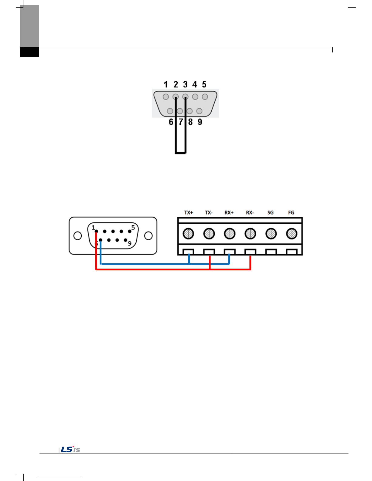
The RS-232C port terminal should be made as follows. (Connect the No.2 and 3 pin)
The RS-485 and RS-422/485 port ter minal sho uld be made as foll ows. (Only eXP40/ 60)
- Connect the RS-485 No.1 with RS-422/485 No.2 and No.4
- Connect the RS-485 No.6 with RS-422/485 No.1 and No.3
eXP20/eXP30-TTA/DC does not provide for the communication diagnostics of RS-485/422 communication.

Chapter 6 Viewing Information of PLC Connection Status
6-1
Chapter 6 Viewing Information of PLC Connection Status
PLC Information, it shows XGT Panel configuration, PLC CPU status and various records.
☜
Remark
You can check the status of PLC connection after project data is transmitted into XGT Panel.

Chapter 6 Viewing Information of PLC Connection Status
6-2
6.1 PLC Communication Configuration Settings
You can select [Settings] button to change PLC communication settings
[PLC information screen]
[PLC Communication Configuration setting]
Remark
- PLC Communication Configuration setting dialog box may look different depending on drivers.
- For further information about the settings, please refer to the PLC user manual.

Chapter 6 Viewing Information of PLC Connection Status
6-3
6.2 Connection Information
You can check the setting items for the connection with PLC such as vender of PLC, target device, connection
type, ip address, connection information and timeout value in the XP-Builder.
[PLC information screen]
[PLC connection information]
[Dialog box Description]
Name
Description
Connection No.
The communication connection No. is displayed from No.0-15.
Vendor
The vendor of the communication target device is displayed.
Target device
The communication target devic e is disp layed.
Connection type
The connection type is displayed
Timeout value
The set-up timeout value is displayed.
Send wait value
The transmission wait value is displayed.
Retry value
In case when timeout occurs during communication, the retry value is displayed.

Chapter 6 Viewing Information of PLC Connection Status
6-4
6.3 PLC Information
You can check CPU type of PLC, operation mode, state, version, and scan time.
Remark
The following PLC is available for view of PLC information.
- MASTER-K CPU, FEnet, Cnet
- GLOFA-GM CPU, FEnet, Cnet
- XGK/XGB/XGI/XGR CPU, FEnet, Cnet
6.4 History of PLC Error
You can check the PLC Error History.
Remark
The following PLC is available for viewing Error History.
- MASTER-K CPU doesn’t have the Error History.
- GLOFA-GM CPU, FEnet, Cnet
- XGK/XGB/XGI/XGR CPU, FEnet, Cnet

Chapter 6 Viewing Information of PLC Connection Status
6-5
6.5 History of PLC Mode Conversion
You can check the history about our PLC’s RUN/STOP operation mode.
Remark
The following PLC is available for viewing PLC operation mode conversion history.
- MASTER-K CPU doesn’t have the history about operation mode conversion.
- GLOFA-GM CPU, FEnet, Cnet
- XGK/XGB/XGI/XGR CPU, FEnet, Cnet
6.6 History of PLC Power
You can check the history about when PLC was turned on and off
Remark
The following PLC is available for viewing the history of when our PLC was turned off and on.
- MASTER-K CPU doesn’t have the history about when our PLC was turned on and off.
- GLOFA-GM CPU, FEnet, Cnet
- XGK/XGB/XGI/XGR CPU, FEnet, Cnet

Chapter 6 Viewing Information of PLC Connection Status
6-6
6.7 History of PLC System
You can check history about PLC system.
Remark
The following PLC is available for viewing history about system.
- MASTER-K CPU doesn’t have the history about system.
- Only GLOFA-GM CPU (GM4C) has the history about system. Other CPUs don’t have the history about system.
- XGK/XGB/XGI/XGR CPU, FEnet, Cnet

Chapter 6 Viewing Information of PLC Connection Status
6-7
6.8 N:1 Settings
Using N:1 communication, it means communicate number of XGT Panel with single PLC.
[PLC information screen]
[N:1 settings dialog box]
[Dialog box setting options]
Name
Description
Use N:1 Communication
The matter of performing N:1 communication is designated.
N:1 station number
The station number of N:1 communication is input.
Number of XGT Panel
The number of XGT Panel in N:1 communication is input.
Master Holding Time
The master holding time of N:1 communication is input.
Remark
For detail information about the N:1 communication, please refer to the XP-Builder manual.

Chapter 6 Viewing Information of PLC Connection Status
6-8
6.9 Program Monitor
The programs that adopt Ladder language of XGK series can be monitored.
Remark
-
Program Monitor driver can be downloaded from XP-Manager.
- Only support for XGK/XGB CPU, Cnet, Enet communication
- To enable the [Program Monitor] button, program monitor should be checked in which locates in the XP-
Builder project property menu.

Chapter 7 Storage Function
7-1
Chapter 7 Storage Function
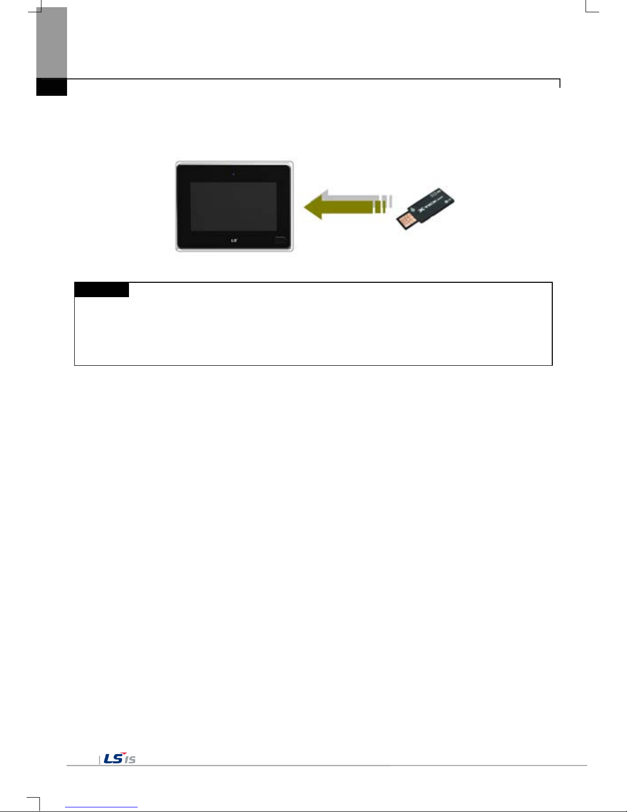
7.1 General Introduction
Downloading the user project made in XP-Builder from PC, uploading the project stored in t he device to PC,
updating the device an d et c are available throu gh connection with XG T Panel with Serial ca ble or Et her net cable
generally. However, when those connections are not available, you can use USB storage equipment
☜
[XGT Panel main screen]
1. If you touch [Storage Function], the following dialog box shows.
2. In case of downloading the project by using USB storage equipment, touch [Project Download] button.
3. In case of transmitting the project data stored in the device to USB storage equipment, touch [Project
Upload] button.
4. In case of updating the XGT Panel wit h XGT Panel Sof tware s tored in USB St orage e quipm ent, touc h [X GT
Panel Update] button.

Chapter 7 Storage Function
7-2
7.2 Downloading Project through t he S t orage Equipment
1. If you touch [Project Download], the following dialog shows.
2. Please select the targeted external memory in “Select Source”. Following path is indicated depending on the
selected external memory.
- USB: \USB Storage\XP_Project\
In case of downloadin g th e pr oj ect by using storage eq uipm ent , th e proj ec t s h oul d be s a ved in th e one lower
directory between those directories.
3. Select one among directory lists and touch [OK].
4. Touch [OK] button, then download is started.

Chapter 7 Storage Function
7-3
7.3 Uploading Project through t he Storage Equipment
1. If you touch [Project Upload], the following dialog shows.
2. Please select the targeted external memory in “Select Source”. Following path is ind icated depending on the
selected external memory
- USB: \USB Storage\XP_Backup\
3. If you touch [OK] button, project backup file is transmitted to the selected path.
4. The project backup file is saved when Download project backup file is selected when downloading the
project. If you don’t select, project back up file is not saved in the device an d transmission to the storage
equipment is not available.

Chapter 7 Storage Function
7-4
7.4 Updating the Device through S tor a ge E quipment
1. If you touch [Project Upload], the following dialog shows.
2. Please select the targeted external memory in “Select Source”. Following path is indicated depending on the
selected external memory
- USB: \USB Storage\XP_Software\
In case of updating the device by using storage equipment, the XGT Panel Software project should be
saved in the one lower directory between those directories.
3. If you touch [OK] button, the device is updated with XGT Panel Software in the designated path.
Chapter 8 XGT Panel S/W Update
8-1
Chapter 8 XGT Panel S/W Update
8.1 General Introduction
It describes the function for updating the XGT Panel software.
Basically you can optimize XGT Panel when you download the project file in X P -B uilder . P le ase us e th is f unc tio n
only in case of updating XGT Panel specially.
New function is added to XGT software, you need to update a version of XGT Panel.
Please refer to the following.
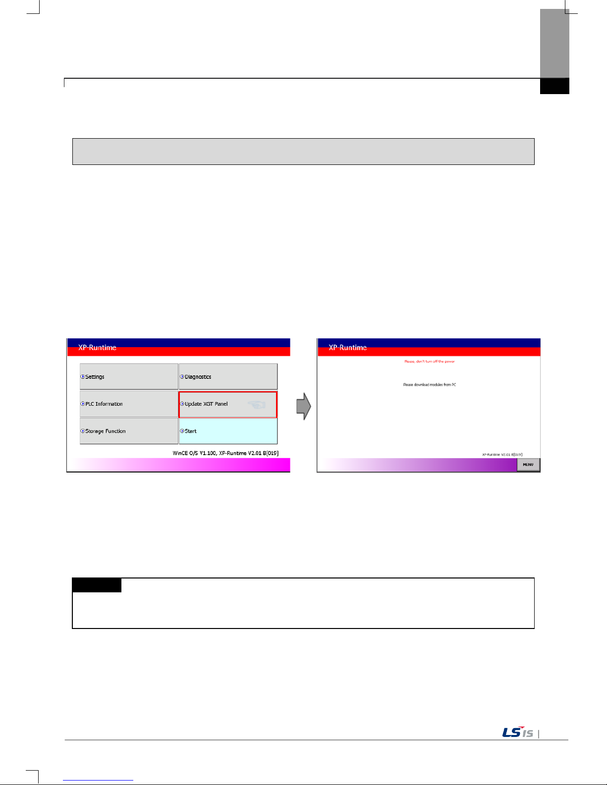
[Method]
Select [Upgrade -> Updat e XGT Panel] on the XGT Panel’s main screen. T hen XGT Panel becomes update
mode. In order to return to the main screen, touch a “MENU” button or touch the screen for 3 seconds
☜
After downloading XGT Panel software from LSIS website, make a temporary folder and save it.
Designate the folder where the software will be saved in the XP-Builder’s [XGT Panel Update] windows and
update XGT Panel by [Send] m enu. For more detailed inform ation about XP-Builder, please ref er to the XPBuilder user manual.
Remark
Do not remove communication cable or turn off the device during updating.
It may cause the abnormal operation.


Chapter 9 File Backup through External Storage Equipment
9-1
Chapter 9 File Backup through External Storage Equipment
Describes on managem ent function about external st orage equipment saving backup data of logging, recipe,
and screen image
(1) XGT Panel can back up the logging, recipe, and screen image data at USB storage equipment according to
setting in XP-Builder.
(2) In case there is no space for back up in the designated storage equipment, it continues back up deleting
previous data or stops backup according to setting in XP-Builder
(3) Monitors attachment status of backup equipment at XP-Builder.

Chapter 9 File Backup through External Storage Equipment
9-2
9.1 Path Structure in case of File Backup
Backup path structure of logging, recipe, and screen image is as follows.
Logging
YYYY.MM.
BeginDay.EndDay.
0
DD.
BeginHour.EndHour.
0 (space for one folder is full)
HH.
BeginMinute.FF
Lhhmmss0.CSV
Recipe
Rhhmmss0.CSV (same as lower structure of each logging number)
DD.
BeginHour.EndHour.
1
DD.
BeginHour. FF
(There is free space for one folder)
1 (Logging Number)
2 (same as lower structure 1)
ScreenImage
Shhmmss0.BMP (same as lower structure of each logging number)
Root directory of CF or USB storage equipment
(There is free space for one folder)

Chapter 9 File Backup through External Storage Equipment
9-3
1. Path structure in case of logging backup
(1) Directory named ‘Logging’ is created under the root directory of USB equipment
(2) The directory whose name is logging number is created under Logging directory.
(3) The directory whose name is year, month is created under Logging number directory.
(a) Includes day directory under
(b) Up to 500 day directories can be created.
(c) Name of year, month directory includes the firstly created day information under its directory
Ex) In case directory is created in 2010, Oc to ber and includes direct ory since 15th under, d ir ectory’s name
is
: 2010.10.15.FF
FF at end means t he direct ory ca n save m ore dat a cre ated i n 201 0, O ctober (c urrentl y, th e num ber of
lower directory is 500 or less)
(d) In case month is changed, changes directory name to day information of last created day directory.
Ex) In case month b ecomes Novem ber from October and direc tory from 15th direc tory to 30th h ave been
created in 2010, October directory.
: 2010.10.15.30.0
(e) Though month is no t ch anged, in cas e the num ber of da y directory under year, m onth dir ector y is 5 00 or
above, directory name is changed into name including day information of last created day directory.
Ex) In case the number of direc tory from first to 15th is 500 or above in the directory create d in 2010,
October.
: 2010.10.01.15.0
(f) In case there is the year, month director y having sam e start day and end da y when changing d irectory’s
name due to over 500 day directories or change of month, last digit index number increases.
Ex) In case there are thre e year, month director ies that are having ov er 500 day directories created in
October first and 2010 year October directory
: 2010.10.01.01.0
: 2010.10.01.01.1
: 2010.10.01.01.2
(4) Day directory is created under year, month directory
(a) Hour directory is created under day directory
(b) Day directory can have up to 500 hour directory
(c) Name of day directory includes not day information but also hour information of first created hour
directory
(d) Relation between da y director y and hour direct ory is s ame as relation b etween year month direc tory and
day directory.
(5) Directory whose name includes hour information is created under day directory.
(a) Hour directory includes backup file under
(b) Hour directory can include up to 500 backup file
(c) Name of time dir ectory include not o nly hour inform ation but also minute inf ormation of first cr eated file
under
(d) Relation between hour direc tory and backup file is sam e as relation between year, m onth directory and
day directory.
(6) Name of logging backup file includes the created hour, minute, second information.
(a) Backup file is created in CSV format.
(b) File name start with ‘L’ meaning logging and includes hour, minute, second, index information
(c) In case backup file is created a t the same time in terms of second, index inf ormation at the end of file
name increases.

Chapter 9 File Backup through External Storage Equipment
9-4
2. Path structure in case of recipe backup
(1) Directory named ‘Recipe’ is created under USB storage equipment root directory.
(2) Year, month directory is created under Recipe directory
(3) The lower directory structure is same as that of logging backup path structure.
(4) Name of recipe backup file includes the created hour, minute, second information.
(a) Backup file is created in CSV format.
(b) File name start with ‘R’ indicating recipe and includes hour, minute, second, index information.
(c) In case backup f ile is created at the sam e time in terms of sec ond, index information at the end of file
name increases.
3. Path structure in case of screen backup
(1) Directory named ‘Screen Image’ is created under USB storage equipment root directory.
(2) Directory whose name is year; month is created under Screen Image directory.
(3) The lower directory structure is same as that of logging.
(4) Name of screen image backup file includes hour, minute, second information.
(a) Backup file is created in bitmap format.
(b) File name starts with ‘S’ and includes hour, minute, second, index information.
(c) In case backup f ile is created at the sam e time in terms of sec ond, index information at the end of file
name increases.
4. Structure of path at memo backup
(1) ‘Memo’ directory will be formed at the sub route directory of USB storage device.
(2) Directory in the name of Year and Month will be formed below the Memo Directory.
(3) Structure of directory thereafter is same as that of logging backup route.
(4) Memo backup file has the name made of hour/minute/second when it was created.
(a) Backup file is created in the type of bitmap.
(b) File name star ts with ‘ M’ that r epresent s the sc reen im age, which includes the ind ex inf ormation of hour,
minute, and second thereafter.
(c) In case backup file is created at the same time up to second, it increases the far end index information.
5. Structure of path at live image recording
(1) ‘Movie’ directory will be formed at the sub route directory of USB storage device.
(2) Recorded live image is stored below the Movie Directory.
(3) Live image file has the name made of year/month/date/hour/minute/second information when it was
created.
(a) Backup file will be created i n AVI type. H. 264 an d MP3 were used for Video CODEC and Audio CODEC
respectively.
(b) File name starts with ‘MOV’ that represents screen image, which includes data and hour information
thereafter.
(c) Live image can be s tored up to the number 1,000 files. This number can be desig nated at the special
device settings of XP-Builder.
6. Structure of path when Blue Screen of camera image and live image is created
(1) ‘MovieStill’ directory will be formed at the sub route directory of USB storage device.
(2) Recorded live image will be stored below MovieStill directory.
(3) Blue screen image f ile has the name made of year/m ont h/date/h our /minute/second inform ation when it w as
created.

Chapter 9 File Backup through External Storage Equipment
9-5
(a) Backup file will be created in JPG type.
(b) File name starts with ‘STL’ that represents screen image, which includes data and hour information
thereafter.
(c) Live image can b e stor ed up to 1,0 00 f iles. T his n um ber c an be des ignate d at the sp ecial d evice s ettin gs
of XP-Builder.
Remark
(1) When changing devic e time, in case of c hanging current time int o after time, we guarant ee the normal
operation. But in case of chang ing curren t tim e into ear l y time, we don’t gu arantee the norm al oper ation.
In this case, you have to delet e directory including the change d hour and its lower director y for normal
operation. For exam ple, if you change time from Decem ber 10
th
to Dec ember 5th, you have to delete
year, month directory created in December 10
th
and restart the device
(2) Sorting by project is not supporte d for eac h logging , recipe, sc reen im age. For example, ther e are no. 1,
2, and 3 logging groups in the project A. And in case each logging group backups the file, 1, 2, 3
directories are creat ed and each d ata is s aved under each directory. Then, in ca se f ile back up occ urs in
the project B having no.1, 2 logging grou p, backup file is creat ed in same direct ory of project A. In th is
case, you have to sort the backup files of project A and B based on the created time.

Chapter 9 File Backup through External Storage Equipment
9-6
9.2 Operation setting whe n there is no space for backup
You can designate in the XP-Bu ilder whether to cance l the backup or delete th e oldest backup file and ex ecute
backup when there is no space in the storage equipment.
[Project Property Setting -> Storage Settings -> Backup Storage -> Delete old file if disk full]
1. In case of backup, deleting the oldest data
(1) In case there is no space for backup, s earches the oldest year, month directory under Logg ing, Recipe,
Screen Image. (But in case of Logging, finds under Logging number directory. That is, when executing
backup about Logging number 2, in c ase there is no back up data in Loggin g number 2 dir ectory and t here
is data only in logging number 1, data of logging number 1 is not searched/deleted.)
(2) Searches the oldest day directory under the oldest year, m onth direc tory.
(3) Searches the oldest hour directory under the oldest day directory.
(4) Deletes the oldest backup file under the oldest hour directory.
(5) Checks the space and if more space is necessar y, the above steps of (1) ~ (4) are repeated a nd checks
the space.
(6) When deleting file, in case all data in time directory are deleted, relevant hour directory is deleted.
(7) When deleting hour directory, in case all hour directories in day directory are deleted, relevant hour
directory is deleted.
(8) When deleting d ay dire ctor y, in case all da y directories in year, month directo ry are d eleted, r elevant year,
month directory is deleted.
Remark
(1) In unknown direc tory or file (user f ile or dir ector y), searches the oldest t hing a mong nor mal bac kup files
except unknown directory or file.
(2) In case there is noth ing except user d ata in now s earched director y, back up operation fails. X GT Panel
can’t delete user data, at this point, operation stops.

Chapter 9 File Backup through External Storage Equipment
9-7
9.3 Monitoring Connection St a t us of External Storage Equipment
XGT Panels monitors conn ection status ab out externa l storage equipm ent designated when setting back up path
in XP-Builder.
The following figure is backup path specified in XP-Builder.
In order to use t his monitoring function, you have to se t about system alarm window, and the n t he pr ojec t s h o uld
be downloaded.
In case USB storage eq uip ment is removed during o p erat ion after setting the pat h f or s avin g L ogg in g backup file
as USB storage equipm ent and download ing the projec t into device, the designated system alarm (HS951.0 ) is
set. In case storage equipment is equipped again, alarm is reset.
In case USB storage equipm ent is rem oved dur ing operatio n after setting the path f or saving R ecipe bac kup f ile

Chapter 9 File Backup through External Storage Equipment
9-8
as USB storage equipm ent and download ing the projec t into device, the designated system alarm (HS951.1 ) is
set. In case storage equipment is equipped again, alarm is reset.
In case USB storage equipment is removed during operation after setting the path for saving Screen Image
backup file as US B storage equipment and downloading the project into device, the design ated system alarm
(HS951.2) is set. In case storage equipment is equipped again, alarm is reset.
Internal address of the designated system alarm can be checked in XP-Builder as follows.

Chapter 10 Installation and Wiring
10-1
Chapter 10 Installation and Wiring
10.1 Installation
10.1.1 Installation environment
This machine has high reliability regardless environment. But for reliability and stability, be careful the followings
(1) Environment condition
(a) Install at the pan el which can protect this m achine f rom water and dus t. XGT Pan el is designed by IP65
Standard in front parts and IP20 Standard in rear par ts .
(b) Install at the place where impact and vibration is not continuously applied. XGT Panel is designed to
meet IEC standard (IEC 61131-2).
(c) Do not expose this machine to direct light.
(d) Do no t install at the place where rapid t emperature change can occur. Mo isture by rapid temperature
change can cause malfunction and damage.
(e) This machine should be installed within 0 ~ 50°C, otherwise the screen may be changed or cause
malfunction
(f) This machine s hould b e installe d within 10~85% relative-hum idit y. Moisture by rap id tem perature ch ange
can cause malfunction and damage.
(g) Avoid corrosive gas and burnable gas.
(h) Dry location use only.
(2) Installation construction
(a) When doing screw’s processing or wir ing construc tion, be careful that the rem ains do not enter th e XGT
Panel inside.
(b) Install at the place where you can easily control.
(c) Do not install with high voltage machine within same Panel.
(d) Keep distance of more than 100mm from duct for wiring and peripheral machine.
(e) Ground at the place where few noises develop.
(3) Anti-heat design of control panel
(a) In case of installing X GT Panel in the a irtight pane l, consider the hea t by other m achine as well as o wn
heat. In case that the air circulates through a ventilating opening or a general pan, XGT Panel system can
be influenced by in-draft of dust or gas.
(b) We recommend you to install a filter or to use an airtight heat exchanger.

Chapter 10 Installation and Wiring
10-2
Remark
(1) Waterproof & dustproof standards
(a) IP65 Standards
1) The protection standards of XGT Panel have been designed to meet the IP65 test conditions, in
accordance with the degrees of protection provided by enclosures of IEC60529.
As this machine inst alled at the pa nel, it is n ot guar ant eed wit h all instal latio n envi ronm ent even though
its protection standards for the front parts are satisfied.
2) IP65 rating guarantees the enclosure is dust proof (6) and protected against jets of water (5).
3) IP20 rating guaran tees p rotection f rom solid foreign objects of 12mm diam eter and great er (2), b ut it
does not guarantee protection from water ingress.
(b) Notices
1) In the environment where the protection grade of XGT Panel is exceeded or not satisfied, the
damage of the device or malfunction can occur due to the failure of protecting the product.
2) Since the protection grade of XGT Panel is the waterproof/du
stproof standards, it cannot be
protected from oil, corrosive gas and metal particles.
3) In case when Gas ket is damaged by chemicals and continuous vibration, its waterproof/dustproof
effect can be weakened.
4) In case when installing the panel, make sure that dust and water are not brought in panels.

Chapter 10 Installation and Wiring
10-3
10.1.2 Notice in handling
It describes the notice from opening to installation.
• Do not drop or cause heavy impact.
• Do not disassemble voluntarily. When doing this, we are not responsible for the product.
• When wiring, be careful that the remains do not enter into XGT Panel.
10.1.3 Notice in installing the panel
Here describes how to install XGT Panel in panel and notice.
(1) Panel cut
• Before installing the XGT Panel in panel, panel should be made with the following dimension.
Classification
X(Wide)
Y(Height)
Z(Thickness)
eXP20-TTA/DC
eXP20-TTA/DC,CERTI
119
+
1
93
+
1
1.6~9.5
-
0 -0
eXP30-TTA(B)/DC
eXP30-TTE/DC
156
+
1
123.5
+
1
-
0 -0
eXP40-TTA(B)/DC
eXP40-TTE/DC
192
+
1
138
+
1
-
0 -0
eXP60-TTA(B)/DC 260
+
1
202
+
1 -0 -0
Unit: [mm]
X
Y
Z

Chapter 10 Installation and Wiring
10-4
(2) XGT Panel installation
• Keep the distance of 100 mm between XGT Panel and panel per each direction.
Remark
(1) To be affected at a mini mum by the electrom agneti c waves ( radial no ise) or heat from other contr ollers,
it needs to keep its distance as the above explanation.
(2) When installing, consider the power and communication cable wiring.
(3) In case when t he size of the pa nel cut exceeds the range of the standard allowanc e(0 ~ +1mm ) when
producing panels, the contact area between Gask et and the panel can get small, which can weaken the
waterproof/dustproof effect.
• W hen mounting the XGT Panel inside a panel, ensure that you use the gasket to protec t against dust or
water ingress.
100
100
100
100
100
Unit: [mm]
Waterproof/Dustproof
Gasket

Chapter 10 Installation and Wiring
10-5
Remark
(1) Must be used the gasket to prevent dust or other contaminant ingress.
(2) When m ounting at the panel, if the surface of panel is uneven, water or dust c an enter the machine
through the gaps. As such problem s can occur de pending on the thickness and material (stee l, aluminum ,
acrylic and etc.) of the panel, it is required to review the installation environm ent. Also it is necessary to
check if Gasket and the panel are closely contacted together.
(3) When Gasket is contam inated or dam aged b y the deterior ation after the use f or a c ertain p erio d of tim e,
the waterproof/dustproof effect can be noticeably weakened. In case when Gasket should be replaced,
contact the agency or a sales office close by.
(3) Installation location
• When installing the XGT Panel, consider screen and use of touch.
• When you don’t see within the following angle, you may not see clearly. When installing, consider angle.
Item
Left and Right
Upper
Lower
eXP20-TTA/DC
eXP20-TTA/DC,CERTI
60 deg. 40 deg. 60 deg.
eXP30-TTA(B)/DC
eXP30-TTE/DC
eXP40-TTA(B)/DC
eXP40-TTE/DC
eXP60-TTA(B)/DC
55 deg.
35 deg.
55 deg.
(4) Fixing
• Fix XGT Panel to the panel using the supplied brackets provided in the packaging.
Fix bracket
Fix bracket
Panel
Fix bracket
Fix bracket

Chapter 10 Installation and Wiring
10-6
Remark
(1) Remove the protection film attached to the front of this machine. Due to the deformation of the
protection film, the touch malfunction or wrong input can occur. It is recommended to use a special
protection sheet to protect the front sheet. In case of purchasing the protection sheet, contact the
agency or a sales office close by.
(5) Removal of protection film
• The film attached to pr ote c t the f r ont s heet when th is machine has been release d, shou ld b e r emoved after
it is installed in the panel.
Remark
(1) During installation, XGT Panel should be closely contacted to the panel not to have any gap. In the
environment requiring waterproof/dustproof effect, install and fix a bracket on a slope.
(2) The brack et s hould be f i xed symmetrically(up-down, left -r ight). In c as e when i t is not f ixed symmetrically,
there could be a gap between the panel and XGT Panel.
(3) When fixing the bracket, it should be installed pe rpendicularly to the panel, and the required bracket
screw torque is 6.7±0.3kgfㆍ
cm. Depending on the m aterial type of the panel, the torque value can be
different. The standard sc rew torque f or each bolt siz e is followed. If it is fixed with t he power mor e than
the required screw torque, the touch malfunction or weakening of waterproof /dustproof can happen d ue
to the deformation of XGT Panel.

Chapter 10 Installation and Wiring
10-7
10.2 Wiring
It describes the wiring that you should know when installing the XGT Panel.
10.2.1 Power wiring
eXP Panel is the DC product.
Power Name
DC 24V
eXP20-TTA/DC, eXP20-TTA/DC,CERTI
eXP30-TTA(B)/DC, eXP30-TTE/DC
eXP40-TTA(B)/DC, eXP40-TTE/DC
eXP60-TTA(B)/DC
► If AC power is applied into the product for DC power, It may cause damage or fire. Be careful
of connection.
► ‘/DC’ is the product which use DC 24V. When using the product, Please check the label
in the back of the product.
► All field-wiring connections to this unit shall be from Limited Voltage/Limited Current, below
24Vdc isolated secondary source with an output fused with a 4A fuse max. or Class 2 secon
-dary circuits as defined in UL 508, 17
th
Edition.
Warning

Chapter 10 Installation and Wiring
10-8
The power terminal should have the following specification.
Type Cable specification (Unit: ㎟) Wire Type Thermal Resistance Screw Torque
Power and protection
ground
1.5(AWG16) ~ 2.5(AWG12) Copper 60℃ 0.51N•m
Remark
(1) For installations where there is voltage drop, it is recommended to use stranded wire with a cross sectional
area greater than 2 ㎟.
(2) It is recommended that cable connections are twisted and secure. Short cable runs are also recommended
between the point of s upply and th e XGT panel.
(3) For safety reasons it is recommended that you use color coded outer sheaths on the conductors to aid safe
terminations.
Wiring of power is as follows.
[DC Power connection]
Remark
(1) Use a regulated power supply transformer when the power fluctuation is bigger than the standard.
(2) If electromagnet ic interf erence is experience d or e xpected use an ins ulation t ransf ormer to protect the
XGT panel from interference.
(3) All f ield-wiring connections to th is unit shall be from Lim ited Voltage/Limited Current, belo w 24V dc
isolated secondary source, Class 2 secondary circuits or SELV/PELV circuits.

Chapter 10 Installation and Wiring
10-9
Separate the XGT Panel power from the I/O device and main circuit device.
Remark
Separate the XGT Pane l power supply cable from the m ain circuit cable (high voltage and c urrent) and
input/output cable. Maintain a minimum separation of 100mmbetween cables.
Use a lightning surge protector to prevent damage from lightning strikes.
Remark
(1) Separate E1, the groun d connection for lightning s urge protector, and E2, the ground connection for
XGT Panel.
(2) Set lightning surge pro tector to below the al lowable surge voltage to pr ovide protection if the voltage
increases to its maximum.
E2
XGT Panel
E1
Surge absorber to prevent the lighting

Chapter 10 Installation and Wiring
10-10
Use an insulation shielding transformer or noise filter when the electromagnetic interference occurs.
Keep the stripped ends of the terminated cables t wis te d and as shor t as pos sib le. When running the wiring a v oid
running the cables for the insulation shielding transformer or noise filter pass through the cable duct.
When you use the m agnetic li ghting contac tor (MC) f or AC/DC, it is recomm ended to use a ferrite core close to
the power terminals as shown below.
Ferrite Core
(CU1130B, E-TECH)
(CU1330G, E-TECH)
(ZCAT3035-1330, TDK)
10.2.2 Ground wiring
(1) Our XGT Panel has enough anti-noise measure, so except that there are many noises specially, the
ground is not needed. When you use the ground connection, refer to the following information.
(2) Use the exclusive ground connection. When you install the ground connection, use the third grounding
resistance (less than 100Ω).
(3) If you cannot use the exclusive ground connection, use the common ground connection like below.
A) Exclusive ground: Best B) Common ground: Good C) Common ground: Poor
(4) Use cables for groun din g/earth co nnec tions b y usin g cable with a cr oss s ectional area gre ater t han 2.0 ㎟.
Install the ground connection as close as possible to the XGT Panel.
Remark
Check and test the grou ndi ng connec tion. If th e co nnec tion is bad or in case of ( B) abo ve, t he XG T Pan el
may malfunction or the communication signals may fail.
XGT Panel
Other
devices
XGT Panel
XGT Panel
3rd grounding connection
3rd grounding connection
Other
devices
Other
devices

Chapter 11 Maintenance
11-1
Chapter 11 Maintenance
To keep the XGT Panel best, examine the XGT Panel.
11.1 Maintenance
Because an error may be developed by environment, the periodic maintenance is needed. You should check the following
categories once or twice every 6 months.
Maintenance category Criterion Action
Power
Within the power change range
(Within −15% / +10%)
Modify the source of electric power in order to be in
the fluctuation range of a permissible voltage.
Environment
Operating
temperature
0 ~ + 50℃
Modify the operating temperature and humidity to be
proper.
Operating
humidity
10 ~ 85%RH
Vibration No vibration
Use the anti-vibration rubber and make a count
measure.
Getting loose of power terminal There is no unwinding Screw the unwound terminal.
Getting loose of
communication connector
There is no unwinding Screw the unwound terminal.
Reserved part
Amount of reserved part and
reservation
Check the status
Refill the insufficiency and improve the reservation.
Gasket installation status
No gap between the gasket and
panel.
Replace gasket or affix brackets firmly
Gasket status No damage or deterioration Replace gasket
11.2 Daily Maintenance
Check the followings daily.
Maintenance category Maintenance contents Criterion Action
Mounting status Check the brackets Should be mounted firmly R etighten screws
Power terminal status
Loose terminal screws Not loose Retighten screws
Reduce the distance between
compressed terminals.
Keep the proper distance. Correction
Communication connector
status
Unwinding of fixed screw Not loose Retighten screws
Indication LED Check the lighting Blue LED should be turned on Refer to the appendix 1.

Chapter 11 Maintenance
11-2
11.3 Periodical Maintenance
Check the followings once or twice every six months and take measure.
Maintenance category
Maintenance
method
Criterion Action
Environment
Surrounding
Temperature
Measure through
Temperature
/Hygrometer Measure
of corrosive gas
0 ~ 50 °C
Modify it to meet
the general standard.
(Environment standard
in the panel)
Surrounding
Humidity
10 ~ 85%RH
Surrounding
pollution degree
No corrosive gas.
XGT Panel
Status
Unwinding, swing Move XGT Panel Fixed firmly Retighten screws
Dust, foreign
matter adhesion
Visual check Not loose -
Connection
status
Looseness
Retighten screw with
Screwdriver
Not loose Retighten screws
Reduce the distance
between compressed
terminals.
Visual check
Keep the proper
distance.
Correction
Loose connectors Visual check Not loose
Wind the fixed screw of
connector
Loose brackets
Retighten screw with
Screwdriver
Not loose Retighten screws
Power voltage maintenance
Check the power
voltage of input terminal
of power by test
AC100~240V: AC85~
264V DC24V: DC19.2 ~
28.8V
Supply
power modification
Battery
Check when battery is
exchanged and voltage
drop is indicated.
(It is expressed
by system alarm)
• Check the total of
power stoppage time
and guarantee
duration
• There is no battery
voltage drop indication
If guarantee duration is
exceeded even tough
there is no battery
voltage drop indication,
change the battery.
LCD Backlight maintenance Visual check
Check the guarantee
duration
When error occurs,
change the backlight.
Touch status
Touch location error
Check at the
Diagnostics
of XGT Panel
Appropriate
touch location
Reset at the setting of
XGT Panel.
Damage of Touch Visual check
There is no damage
or deterioration
When error occurs,
change touch
Damage or Deterioration
of protection sheet
Visual check
There is no damage
or deterioration
When error occurs,
Change protection
sheet

Chapter 11 Maintenance
11-3
Remark
(1) Battery exchange tim e is express ed by alarm . System alarm is ex pressed when s ystem alarm category
is set at the XP-Builder as follows.
(2) Replace Battery With Hitachi Maxell, Part No. CR2032 Only. Use of Another Battery May Present A Risk
Of Fire or Explosion. See Owner's Manual For Safety Instructions.
WARNING: Battery may explode if mistreated. Do not recharge, disassemble or dispose of in fire.
(3) As the eXP model has the integrated LCD and backlight, the LC D should be replaced when the life is
over or it is out of order.


Chapter 12 EMC Standard Certification
12-1
Chapter 12 EMC Standard Certification
12.1 Requirement for EMC Standard Certification
EMC command is regu lated on “It doesn’t produce the Strong electromagnetic waves: Emission” and “It is not
affected by electrom agnetic wave f rom external: Imm unity”. The fol lowing is desc ribing the contents to meet the
EMC command when configuring the system by using the XGT Panel. This is a summary document for the
request and standard which our company has obtained from EMC but we don't assure that all devices
manufactured accor ding to thes e contents are not suitabl e f or t he be lo w sta nd ard s . The final manufact urer needs
to finally judge about the fitness method or fitness judgment of EMC command.
12.1.1 CE standard certif icat i on
In case of XGT Panel, the EN61000 -6-4, EN61000 -6-2, EN61000-3-2, and E N61000-3-3 of CE standards were
applied.
Applied Standards Results
1. Emission
Conducted Disturbance EN61000-6-4:2007 / A1 : 2011 C
Radiated Disturbance EN61000-6-4:2007 / A1 : 2011 C
Harmonic Current Emission EN61000-3-2:2014 N/T
Voltage Change, Fluctuations and Flicker
EN61000-3-3:2013
N/T
2. Immunity
Electrostatic Discharge
EN61000-6-2:2005 / AC : 2005
C
EN61000-4-2:2009
Radio-Frequency Electromagnetic Field
EN61000-6-2:2005 / AC : 2005
C
EN61000-4-3:2006 / A1 : 2008 / A2 : 2010
Fast Transient
EN61000-6-2:2005 / AC : 2005
C
EN61000-4-4:2004 / A1 : 2010
Radio-Frequency Continuous C onduc ted
EN61000-6-2:2005 / AC : 2005
C
EN61000-4-6:2009
Power-Frequency Magnetic Fields
EN61000-6-2:2005 / AC : 2005
N/T
EN61000-4-8:2010
Surges
EN61000-6-2:2005 / AC : 2005
C
EN61000-4-5:2006
Voltage Dips and Interruptions
EN61000-6-2:2005 / AC : 2005
N/T
EN61000-4-11:2004
C=Comply NC=Not Comply N/T=Not Tested N/A=Not Applicable
Directive:
Electromagnetic Compatibility Directive 2004/108/EC

Chapter 12 EMC Standard Certification
12-2
12.1.2 KC standard certification
The XGT Panel acquire the electromagnetic fitness registration (KC specification) certified by wave laboratory
under information-communication part.
A grade device
This device acquires KC for industrial use.
If device is not purchased properly, exchange it to device for home use.
12.2 Requirement for Low Volt a ge Comma nd S uitability
It is required to get the needed Stability for t he device operated at AC50~1000V, DC75~1500V’s power. The
following describes at tention about instal lation and wiring f or the suitability when using the XGT Pane l. Though
the following data is m ade by requirement of regulati on and standard, we don’t guarantee that all devices are
suitable for the above c ommand. The method to be suitable for the EMC com mand and judgment of s uitability
should be finally made by device manufacturer himself.
12.2.1 Standard certification for XGT Panel
XGT Panel is according to the EN61131-2:2007 (stability of device used in the measure, control laboratory).
12.2.2 Selection of XGT Panel
(1) eXP20-TTA/DC, eXP20-TTA/DC,CERTI, eXP30-TTA(B)/DC, eXP30-TTE/DC, eXP40-TTA(B)/DC,
eXP40-TTE/DC, eXP60-TTA(B)/DC
The I/O module under DC24V exceeds the range of low voltage command target.

Appendix 1 Troubleshooting
App1-1
Appendix 1 Troubleshooting
1. Type of Problem
It classifies problems from XGT Panel including an indicated figure, indication of the object, and problems
appeared when downloading. Refer to the following chart.
Classification of
problem
Description
Problem when starting
Malfunction when starting.
☞
Please refer to the 2. Problem when starting.
Problem after the
monitor on
In case that there is no reaction when touching.
☞
Please refer to the 3. Problem after the Monitor on.
Display problem of
figure and object.
In case that the figure or object is different from when editing.
☞
Please refer to the 4. Indication problem of figure and object.
Communication problem
In case that communication is not executed properly.
☞
Please refer to the 5. Communication problem.
USB Removal of
Memory Card
In case that USB device is not working for a while when USB memory is removed.
☞
Please refer to the 6. USB Removal of Memory Card
Error message
when executing program
In case that an error message occurs when operating the XGT Panel.
☞
Please refer to the 7. Error message when executing program.
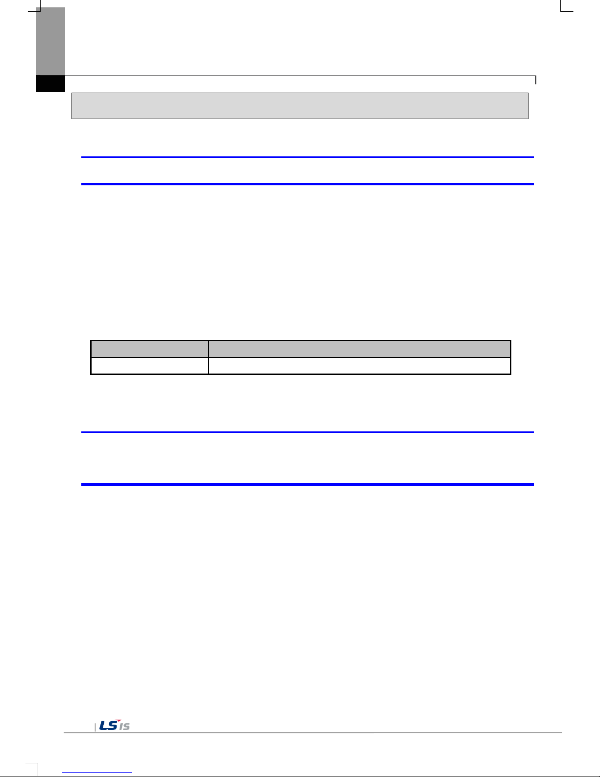
Appendix 1 Troubleshooting
App1-2
2. Problem when Starting
Why does black screen show up when turning on the device?
Phenomenon: When turning on the device, black screen shows up and the booting is impossible.
< Cause >
(1) Because the device is not set as a booting mode.
(2) Black screen may appear because of malfunction of backlight.
<Solution>
(1) Because the device is not set as a booting mode, the above problem can occur.
Check whether No. 5 switch at DIP switch in the back of the device is in B direction or not.
B direction is a booting mode.
When is the color of LED changed?
Please check the followings.
Display color
Contents
BLUE
Power is supplied to XGT Panel
When applying the option, ‘Go to Screen after boot up’, it displays “Failed to load image files” as the
monitoring has not been started.
Phenomenon: After storing images in the USB storage device and then selecting the option “Go to Screen
after boot up” in the start menu, in case when re-permitting the power of the equipment, the message like
“Failed to load image files” is displayed and the monitoring is not started.
<Cause>
(1) In case when it is connected with the USB storage device, the recognition of the USB is delayed.
<Solution>
(1) In case when the recognition speed is delayed due to the characteristics of the USB storage device,
remove the USB storage device and then reinstall it.

Appendix 1 Troubleshooting
App1-3
When the power is re-permitted, the USB storage device (or USB mouse) is not recognized.
Phenomenon: When the USB storage device was initially installed, it was normally recognized. However, it is
not recognized after the power is re-permitted.
<Causes>
(1) Due to the option of the ‘Reset USB Power’ of the equipment, there could problems in the recognition
process.
(2) Depending on the USB storage device, it may not be smoothly recognized.
<Solution>
(1) If the power initialization option(“Reset USB Power”) of the equipment is selected, cancel the selection
and then permit the power again. The “Reset USB Power” option is an additional function to improve
the initialization of the storage device with slow recognition speed or low recognition ratio. Depending
on the characteristics of the storage device, however, the power initialization can be an obstacle to the
initialization work. Thus, depending on Phenomenon, select what has higher recognition ratio by
properly using the power initialization option.
(2) Depending on the characteristics of the storage device, it may not be recognized. Use another USB
storage device showing higher recognition ratio.

Appendix 1 Troubleshooting
App1-4
3. Problem after the Monitor on
When touching the screen it reacts in a different area or it may not react at all?
Phenomenon: When touching the screen it reacts in a different area or it may not react at all.
< Cause >
(1)Touch’s Calibration setting is not proper.
(2) Touch panel may be a break down.
<Solution>
(1) Redo Calibration setting about touch. Refer to the [Device manual Ch.4.1 Touch Calibration].
(2) It you can’t go to setting menu, connect mouse to USB port and use mouse.
Buzzer does not sound.
Phenomenon: When pressing buzzer, buzzer does not sound.
< Cause >
(1) When that the switch operates but the buzzer doesn’t sound, the buzzer is set as no sound.
(2) If the switch doesn’t work too, it seems that some error occurs in the touch function.
<Solution>
(1) Redo environment setting for buzzer to sound. Refer to the [device manual Ch.4.7 Environment Setting].
(2) After setting to use buzzer, check whether the buzzer sounds or not in the 1)’s setting windows.
Phenomenon: After the system alarm about the lack of system memory occurs, XGT Panel itself closes the
monitoring and then moves to the start menu in unspecific time without user’s operation.
<Causes>
(1) The memory usage could be exceeding 95%.
(2) The memory usage can be a bit increased when floating pop-up windows or moving to several screens
during monitoring. In case when the number of image used for project is a lot, the memory usage can
more easily reach the limit. In this case, XGT Panel closes the monitoring by itself and then takes an
action to secure the memory again.
<Solution>
(1) In case of using vector image instead of raster image, the memory share can be reduced. In the graphic
library of XP-Builder, the image group marked as OOO_R is the raster image group while the image
group marked as OOO_V is the vector image group.
(2) In case when the monitoring is closed down due to the increase of the memory share in spite of the
image change operation, contact the A/S center close by.

Appendix 1 Troubleshooting
App1-5
After continuously adding projects to the screen, and adding/editing objects, the operation speed has
been slowed down.
Phenomenon: After adding projects to the screen and also adding/editing objects, it feels like the operation
speed of XGT Panel gets slowed down.
<Causes>
(1) The amount of image used for projects is big.
(2) In order to increase the screen operation speed, XGT Panel maintains the used images in the memory in
advance. Since the memory resource has limitation, they cannot be maintained in the memory once the
amount of image exceeds a certain limit. Whenever they are needed, thus, they are read from the file
system and then expressed on the screen. This could be the reason why the screen operation speed gets
slowed down.
<Solution>
(1) In case of using vector image instead of raster image, the memory share can be reduced. In the graphic
library of XP-Builder, the image group marked as OOO_R is the raster image group while the image
group marked as OOO_V is the vector image group.
(2) In case when there is no proper vector image, the desired image can be composed by using various
functions of figures (circle, square, straight line and etc.).
(3) Removing unnecessary background screen, the screen is composed by applying the background colors.

Appendix 1 Troubleshooting
App1-6
4. Display Problem of Figure and Object
The shape of object is not shown or the number or character value which has to be shown is not shown.
Phenomenon: The shape of object is not shown or the number or character value which has to be sho wn is
not shown.
<Cause>
(1) The connection with PLC connected with each project is disconnected or NAK occurs.
<Solution>
(1) When the communication is executed at first, Check the cable connected with PLC is OK or not.
(2) If object where the offset is set is not shown, check whether address range is exceeded or not.
(3) In case that comm unication is not OK, when c ommunication is abnor mal, the following m essage shows
up in the XGT Panel.
Object type Phenomenon
Bit Switch
The switch is expressed but it doesn’t work .
Word Switch
The switch is expressed but it doesn’t work.
Change Screen Switch
The switch is expressed but it doesn’t work.
Special Switch
The switch is expressed but it doesn’t work.
Multi Switch
The switch is expressed but it doesn’t work.
Bit Lamp
Image is not shown.
Word Lamp Image is not shown.
N-State Lamp
Image is not shown.
Clock
Present time is shown.
Bit Message
Message is not sho wn. W hen designat ing the backgr ound im age, im age is sho wn
as it is.
Word Message
Message is not sho wn. W hen designat ing the back ground im age, im age is sho wn
as it is.
Numeric Display
The value is not shown. W hen d es ig nat ing t he b ackground image, image is s ho wn
as it is.
Numeric input
The value is not shown. W hen d es ig nat ing t he b ackground image, image is s ho wn
as it is.
Text Display
Character string is n ot shown. W hen designating the back ground image, image is
shown as it is.
Text Input
Character string is n ot shown. W hen designating the back ground image, image is
shown as it is.
Bit Window
The window screen set in the obj ect is not s hown. B ut if comm unication is s et with
other object in the same window screen, it can be shown by that object.
Word Window
The window screen set in the obj ect is not s hown. B ut if comm unication is s et with
other object in the same window screen, it can be shown by that object.
Bit Part
The part screen set in the object is not sho wn. But if communication is set with
other object in the same part screen, it can be shown by that object.
Word Part
The part screen set in the object is not shown.

Appendix 1 Troubleshooting
App1-7
Object type Phenomenon
But if communication is set with other object in the sam e part screen, it can be
shown by that object.
Animation
Animation is not shown.
Bar Graph
Graph is not shown. W hen designat ing the back ground im age, image is shown as
it is.
Pie Graph
Graph is not shown. W hen designat ing the back ground im age, image is shown as
it is.
Meter Graph
Graph is not shown. W hen designat ing the back ground im age, image is shown as
it is.
Closed Graph
Graph is not shown. W hen designating the back ground im age, image is s hown as
it is.
Trend Graph
X, Y axis is shown normally but trend axis is not normally shown.
When designating the background image, image is shown as it is.
History Alarm Viewer
Change doesn’t occur. When communication is abnormal, alarm occurs because it
can’t know the status of ala rm tar get device . But pr ev ious al arm data sho ws up a s
it is.
Data list
Value is not shown. Lattice of viewing data list of object is shown as it is.
Logging Viewer
Change doesn’t occur. W hen communication is normal, the recor ded log data is
shown normally. But, log data is shown as # when communication is abnormal.
Navigator
Change doesn’t occur. Because it shows the group of alarm already developed,
though communication is abnormal, if it has alarm data already developed, it
shows the name of group where each alarm is included.
The number indication object value is shown as # or ~.
Phenomenon: The number indication object value is shown as # or ~.
(Same phenomenon occurs at the number input device, viewing data list, and viewing logging)
<Cause>
(1) This happens when digit is not correct or type is not BCD.
<Solution>
(1) When the number to be ex pressed exc eeds the num ber set in the objec t, # is expr essed. In cas e of this,
set the digit largely and after download again, execute program again.
(2) When the numeric display object is expressed as BCD type, the data whose type is not BCD is
expressed as ~. In case of this, adjust device value as BCD type.
(3) This phenomenon occurs at the data list object, numeric input, numeric display device, and logging
viewer.
 Loading...