

LSI Xw6200 - Workstation - 2 GB RAM, Xw8200 - Workstation - 1 GB RAM, Integrated RAID User Manual
Page 1

USER’S
GUIDE
Integrated RAID
July 2003
Version 1.0 - Preliminary
®
DB15-000292-00
Page 2

This document is preliminary. As such, it contains data derived from functional
simulations and performance estimates. LSI Logic has not verified either the
functional descriptions, or the electrical and mechanical specifications using
production parts.
This document contains proprietary information of LSI Logic Corporation. The
information contained herein is not to be used by or disclosed to third parties
without the express written permission of an officer of LSI Logic Corporation.
LSI Logic products are not intended for use in life-support appliances, devices,
or systems. Use of any LSI Logic product in such applications without written
consent of the appropriate LSI Logic officer is prohibited.
Document DB15-000292-00, Version 1.0 (July 2003)
This document describes LSI Logic Corporation’s Integrated RAID (IR) software
product and will remain the official reference source for all revisions/releases of
this product until rescinded by an update.
LSI Logic Corporation reserves the right to make changes to any products herein
at any time without notice. LSI Logic does not assume any responsibility or
liability arising out of the application or use of any product described herein,
except as expressly agreed to in writing by LSI Logic; nor does the purchase or
use of a product from LSI Logic convey a license under any patent rights,
copyrights, trademark rights, or any other of the intellectual property rights of
LSI Logic or third parties.
Copyright © 2003 by LSI Logic Corporation. All rights reserved.
TRADEMARK ACKNOWLEDGMENT
LSI Logic, the LSI Logic logo design, Fusion-MPT, Integrated Mirroring, and
Integrated Striping are trademarks or registered trademarks of LSI Logic
Corporation. ARM is a registered trademark of ARM Ltd., used under license.
Windows and Windows NT are registered trademarks of Microsoft Corporation.
Linux is a registered trademark of Linus Torvalds. SuSE is a registered trademark
of SuSE Linux AG. RED HAT is a registered trademark of Red Hat, Inc. All other
brand and product names may be trademarks of their respective companies.
KL
To receive product literature, visit us at http://www.lsilogic.com.
For a current list of our distributors, sales offices, and design resource
centers, view our web page located at
http://www.lsilogic.com/contacts/index.html
ii
Version 1.0 Copyright © 2003 by LSI Logic Corporation. All rights reserved.
Page 3

Audience
Preface
This user’s guide explains how to configure and use the components of
the LSI Logic Integrated RAID (IR) software product.
This user’s guide assumes that you have some familiarity with installing
and configuring software programs and that you are familiar with
computer storage devices in general. The people who benefit from this
document are:
• VARs and OEMs who are evaluating the LSI Logic IR software
components or who are using the IR software product in their
computer systems
• End users who are using the IR software product to configure
mirrored or striped volumes.
Organization
This document has the following chapters and appendixes:
• Chapter 1, Introduction to Integrated RAID, provides an overview
of Integrated RAID, its features, and its benefits.
• Chapter 2, Integrated Mirroring (IM) Overview, This chapter
provides an overview of the LSI Logic Integrated Mirroring™ (IM)
feature.
• Chapter 3, Setting Up Integrated Mirroring, describes how to set
up Integrated Mirroring (IM) using the BIOS-based configuration
utility.
• Chapter 4, Integrated Striping (IS) Overview, provides an overview
of the LSI Logic Integrated Striping™ (IS) feature.
Integrated RAID User’s Guide iii
Version 1.0 Copyright © 2003 by LSI Logic Corporation. All rights reserved.
Page 4

• Chapter 5, Setting Up Integrated Striping, describes how to set up
Integrated Striping (IS) using the BIOS-based configuration utility.
• Chapter 6, CIM Solution, describes the Fusion-MPT™ Common
Information Model (CIM) Solution and explains how it is used to
monitor storage components, including mirrored and striped
volumes, in multiple systems on a network.
• Appendix A, Using the DOS-Based Configuration Utility,
describes how to set up Integrated Mirroring or Integrated Striping
volumes using the DOS-based configuration utility (for manufacturing
use only).
Related Publications
LSI Logic Documents
Fusion-MPT Device Management User’s Guide, Version 2.0,
DB15-000186-02
LSI Logic World Wide Web Home Page
www.lsilogic.com
Conventions Used in This Manual
The first time a word or phrase is defined in this manual, it is italicized.
Hexadecimal numbers are indicated by the prefix “0x” —for example,
0x32CF. Binary numbers are indicated by the prefix “0b” —for example,
0b0011.0010.1100.1111.
Revision History
Revision Date Remarks
Preliminary
Version 1.0
iv Preface
6/2003 Initial release of document.
Version 1.0 Copyright © 2003 by LSI Logic Corporation. All rights reserved.
Page 5

Contents
Chapter 1
Introduction to Integrated RAID
1.1 Introduction 1-1
1.2 Integrated RAID Benefits and Features 1-2
1.3 Using this Manual 1-2
Chapter 2
Integrated Mirroring (IM) Overview
2.1 Introduction 2-1
2.2 Features 2-2
2.3 Description 2-3
2.4 Integrated Mirroring Firmware 2-5
2.4.1 Host Interface 2-5
2.4.2 Resynchronization with Concurrent Host I/O
2.4.3 Meta Data Support 2-5
2.4.4 Hot Swap 2-6
2.4.5 SMART Support 2-6
2.4.6 Floating Hot Spare 2-6
2.4.7 Media Verification 2-7
2.4.8 SCSI ID Assignment 2-7
2.4.9 Disk Write Caching 2-7
2.4.10 NVSRAM Usage 2-7
2.5 Fusion-MPT Support 2-8
2.5.1 BIOS ROM 2-8
2.5.2 OS Drivers 2-8
Operation 2-5
Integrated RAID User’s Guide v
Version 1.0 Copyright © 2003 by LSI Logic Corporation. All rights reserved.
Page 6

Chapter 3
Setting Up Integrated Mirroring
3.1 IM Configuration Overview 3-1
3.2 Configuring IM with the BIOS-Based CU 3-2
3.2.1 Quick IM Configuration Procedure 3-2
3.2.2 Configuration Screen Overview 3-4
3.2.3 Detailed IM Configuration Procedure 3-5
3.2.4 Other BIOS-Based CU Screens 3-11
3.3 Troubleshooting 3-14
3.3.1 RAID Properties Menu Item Disabled 3-14
3.3.2 IM Volume Uses Extra SCSI ID 3-14
3.3.3 Configuration Utility Disables Selection of Disk 3-15
Chapter 4
Integrated Striping (IS) Overview
4.1 Introduction 4-1
4.2 IS Features 4-2
4.3 IS Description 4-2
4.4 Integrated Striping Firmware 4-4
4.4.1 Host Interface 4-4
4.4.2 Meta Data Support 4-4
4.4.3 SMART Support 4-4
4.4.4 SCSI ID Assignment 4-4
4.4.5 Disk Write Caching 4-5
4.5 Fusion-MPT Support 4-5
4.5.1 BIOS ROM 4-5
4.5.2 OS Drivers 4-5
Chapter 5
Setting Up Integrated Striping
5.1 IS Configuration Overview 5-1
5.2 Configuring IS with the BIOS-Based CU 5-2
5.2.1 Quick IS Configuration Procedure 5-2
5.2.2 Configuration Screen Overview 5-3
5.2.3 Detailed IS Configuration Procedure 5-4
5.2.4 Other BIOS-Based CU Screens 5-9
5.3 Troubleshooting 5-11
vi Contents
Version 1.0 Copyright © 2003 by LSI Logic Corporation. All rights reserved.
Page 7

5.3.1 RAID Properties Menu Item Disabled 5-11
5.3.2 Configuration Utility Disables Selection of Disk 5-12
Chapter 6
CIM Solution
6.1 Description 6-1
6.1.1 Features 6-2
6.1.2 Installation and System Requirements 6-3
6.2 CIM Browser Window Description 6-4
6.2.1 Connect Menu Options 6-4
6.2.2 Hardware Device Tree Options 6-4
6.3 CIM Installation Instructions for Windows 6-8
6.3.1 Installing the CIM Solution 6-8
6.3.2 Uninstalling the CIM Solution 6-8
6.4 CIM Installation Instructions for Linux 6-9
6.4.1 Installing the CIM Solution 6-9
6.4.2 Uninstalling the CIM Solution 6-9
Appendix A
Using the DOS-Based Configuration Utility
A.1 Configuration Overview A-1
A.2 Running the DOS-Based CU A-2
A.3 Rules for Command Line Options A-3
A.4 Configuring an IM Volume with the DOS-Based CU A-3
A.4.1 Command Line Options A-4
A.4.2 Making Manufacturing Settings Read Only A-7
A.4.3 IM Parameter Defaults for Fusion-MPT SCSI
Controllers A-7
A.4.4 Examples of Command Line Usage A-8
A.5 Configuring an IS Volume with the DOS-Based CU A-10
A.5.1 Command Line Options A-10
A.5.2 Making Manufacturing Settings Read Only A-12
A.5.3 IS Parameter Defaults for Fusion-MPT SCSI Controllers
A-13
A.5.4 Examples of Command Line Usage A-13
Customer Feedback
Contents vii
Version 1.0 Copyright © 2003 by LSI Logic Corporation. All rights reserved.
Page 8

viii Contents
Version 1.0 Copyright © 2003 by LSI Logic Corporation. All rights reserved.
Page 9

Figures
2.1 Typical Mainboard Implementation 2-3
2.2 Integrated Mirroring with Two Disks 2-4
2.3 Integrated Mirroring with More than Two Disks 2-4
3.1 Screen Field Definitions 3-4
3.2 Main Screen 3-5
3.3 Adapter Properties Screen 3-6
3.4 RAID Properties Screen: No IM Volume Configured 3-7
3.5 RAID Properties Screen: One IM Volume Configured 3-10
3.6 Global Properties Screen 3-11
3.7 Boot Adapter List Screen 3-12
3.8 Device Properties Screen 3-13
4.1 Integrated Striping Example 4-3
4.2 Integrated Striping - Logical and Physical Views 4-3
5.1 Screen Field Definitions 5-3
5.2 Main Screen 5-4
5.3 Adapter Properties Screen 5-5
5.4 RAID Properties Screen: No IS Volume Configured 5-6
5.5 RAID Properties Screen: One IS Volume Configured 5-8
5.6 Global Properties Screen 5-9
5.7 Boot Adapter List Screen 5-10
5.8 Device Properties Screen 5-11
6.1 Hardware Device Tree Structures 6-6
Version 1.0 Copyright © 2003 by LSI Logic Corporation. All rights reserved.
ix
Page 10

x
Version 1.0 Copyright © 2003 by LSI Logic Corporation. All rights reserved.
Page 11

Tables
6.1 Connect Menu Option Description 6-4
6.2 Device Tree Description 6-7
Version 1.0 Copyright © 2003 by LSI Logic Corporation. All rights reserved.
xi
Page 12

xii
Version 1.0 Copyright © 2003 by LSI Logic Corporation. All rights reserved.
Page 13

Chapter 1
Introduction to Integrated RAID
This chapter provides an overview of Integrated RAID, its features, and
its benefits. The chapter includes these sections:
• Section 1.1, “Introduction,” page 1-1
• Section 1.2, “Integrated RAID Benefits and Features,” page 1-2
• Section 1.3, “Using this Manual,” page 1-2
1.1 Introduction
The LSI Logic Integrated RAID solution provides cost benefits for the
server or workstation market where the extra performance, storage
capacity, and/or redundancy of a RAID configuration are required. The
two components of Integrated RAID are:
• Integrated Mirroring (IM), which provides features of RAID 1 and
RAID 1E
• Integrated Striping (IS), which provides features of RAID 0
By simplifying the IM and IS configuration options and by providing
firmware support in its host adapters, LSI Logic can offer the Integrated
RAID solution at a lower cost than a full-blown RAID implementation.
LSI Logic CIM interface software is used to continuously monitor IM
volumes and IS volumes and to report status and error conditions as they
arise.
IM and IS are supported by different versions of Fusion-MPT firmware.
Therefore, either IM or IS can be implemented on a system with a
Fusion-MPT based controller, but IM and IS cannot be used concurrently
on the same system.
Integrated RAID User’s Guide 1-1
Version 1.0 Copyright © 2003 by LSI Logic Corporation. All rights reserved.
Page 14

1.2 Integrated RAID Benefits and Features
• Low cost single-volume RAID fills the needs of most internal RAID
installations
• Easy to use - installation and configuration are not complex
• System can boot from an IM or IS volume
• No special OS-specific software required
• High reliability and data integrity
– Non-volatile write journaling
– Physical disks not visible to OS or to application software
• Low host CPU and PCI bus utilization
• Fusion-MPT architecture provides processing power
– 160 MHz ARM966 processors provide maximum processing
capacity
– Shared memory architecture minimizes external memory
requests
– Functionality is contained in device hardware and firmware
1.3 Using this Manual
• Chapters 2 and 3 of this User’s Guide explain how to configure an
Integrated Mirroring (IM) volume.
• Chapters 4 and 5 explain how to configure an Integrated Striping (IS)
volume.
• Chapter 6 explains how to install CIM and how to use it to monitor
IM and IS volumes.
• Appendix A explains how to use the DOS-based configuration utility
to configure IM and IS volumes in the manufacturing environment.
1-2 Introduction to Integrated RAID
Version 1.0 Copyright © 2003 by LSI Logic Corporation. All rights reserved.
Page 15

Chapter 2
Integrated Mirroring (IM)
Overview
This chapter provides an overview of the LSI Logic Integrated Mirroring
(IM) feature and includes these sections:
• Section 2.1, “Introduction,” page 2-1
• Section 2.2, “Features,” page 2-2
• Section 2.3, “Description,” page 2-3
• Section 2.4, “Integrated Mirroring Firmware,” page 2-5
• Section 2.5, “Fusion-MPT Support,” page 2-8
2.1 Introduction
As a result of the shift towards Network Attached Storage (NAS), ISPs
need a cost effective, fault-tolerant solution to protect the operating
systems on small form factor, high-density, rack-mountable servers. The
LSI Logic Integrated Mirroring (IM) feature provides data protection for
the system boot volume to safeguard critical information such as the
operating system on servers and high performance workstations. This
new Integrated Mirroring feature gives customers a robust, highperformance, fault-tolerant solution that is less expensive than a
dedicated RAID controller.
The IM feature provides simultaneous mirroring on configurations of two
to six disk disks, to assure fault tolerant, high availability data. If a disk
fails, the hot swap capability allows the system to be easily restored by
simply swapping disks. The system then automatically re-mirrors the
swapped disk. Additionally, the hot spare feature keeps one disk ready
to automatically replace a failed disk in the volume, making the system
even more fault-tolerant.
Integrated RAID User’s Guide 2-1
Version 1.0 Copyright © 2003 by LSI Logic Corporation. All rights reserved.
Page 16

2.2 Features
The IM feature uses the same device drivers as the standard FusionMPT based controllers, providing seamless and transparent fault
tolerance. This eliminates the need for complex backup software or
expensive RAID hardware. The IM feature operates independently from
the operating system, in order to conserve system resources. The BIOSbased configuration utility makes it easy to configure a mirrored volume.
The IM feature is currently available as an optional component of the new
Fusion-MPT architecture on all LSI Logic Ultra320 SCSI integrated I/O
controller products.
This section lists the key features of Integrated Mirroring.
• Supports configurations of two to six mirrored disks on the same
channel
• Mirrored volume runs in optimal mode or degraded mode (that is, if
one mirrored disk fails)
• (Optional) Supports configuration of a hot spare
• Hot swap capability
• Presents a single virtual drive to the OS
• Support for disks of different types and capacities
• Fusion-MPT architecture
• Easy-to-use BIOS-based configuration utility (and DOS-based
configuration utility for manufacturing use only)
• Support for greater volume capacity by integrating more disks
• Error notification
– OS-specific event log
– Errors displayed on CIM browser
• SAF-TE drive status LED support for Integrated Mirroring disks
• Write journaling, which allows automatic synchronization of
potentially inconsistent data after unexpected power-down situations
• Meta data used to store volume configuration on mirrored disks
2-2 Integrated Mirroring (IM) Overview
Version 1.0 Copyright © 2003 by LSI Logic Corporation. All rights reserved.
Page 17

• Automatic background resynchronization while host I/Os continue
• Media verification
2.3 Description
The LSI Logic Integrated Mirroring (IM) feature provides mirroring for the
boot volume, as shown in Figure 2.1. This is accomplished through the
firmware of an LSI Logic controller that supports the standard FusionMPT interface. The runtime mirroring of the boot disk is transparent to
the BIOS, drivers, and operating system. Host-based status software
monitors the state of the mirrored disks and reports any error conditions.
In Figure 2.1 the system is configured with a second disk as a mirror of
the first (primary) disk.
Figure 2.1 Typical Mainboard Implementation
Internal
SCSI
Two Disk Drives
OS Mirrored
OS
NVSRAM
(For Write Journaling)
LSI Logic
Fusion-MPT
Controller
MemoryExternal
BusSCSI
EEPROM
(For Configuration)
Figure 2.2 shows the logical view and physical view of the mirroring
configuration when there are two disks in the mirrored volume.
Description 2-3
Version 1.0 Copyright © 2003 by LSI Logic Corporation. All rights reserved.
Page 18
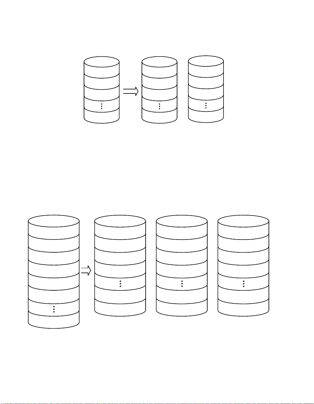
Figure 2.2 Integrated Mirroring with Two Disks
Logical View Physical View
LBA 1
LBA 2
LBA 3
LBA N
LBA 1
LBA 2
LBA 3
LBA N
LBA 1’
LBA 2’
+
LBA 3’
LBA N’
Mirroring can also be configured with up to 6 mirrored disks, or 5
mirrored disks and a hot spare. Figure 2.3 shows the logical view and
physical view of the mirroring configuration with more than two disks in
the mirrored volume. Each “mirrored stripe” is written to a disk and is
mirrored to an “adjacent” disk. This is commonly referred to as RAID 1E.
Figure 2.3 Integrated Mirroring with More than Two Disks
Logical View Physical View
Mirrored Stripe 1
Mirrored Stripe 2
Mirrored Stripe 1
Mirrored Stripe 3’
Mirrored Stripe 2
Mirrored Stripe 1’
Mirrored Stripe 3
Mirrored Stripe 2’
Mirrored Stripe 3
Mirrored Stripe 4
Mirrored Stripe 5
Mirrored Stripe 6
Mirrored Stripe n
Mirrored Stripe 4
Mirrored Stripe 6’
Mirrored Stripe n-2
Mirrored Stripe n’
Mirrored Stripe 5
+
Mirrored Stripe 4’
Mirrored Stripe n-1
Mirrored Stripe (n-2)’
LSI Logic provides the BIOS-based configuration utility to enable the
user to configure the mirroring attributes during initial setup and to
reconfigure them in response to hardware failures or changes in the
2-4 Integrated Mirroring (IM) Overview
Version 1.0 Copyright © 2003 by LSI Logic Corporation. All rights reserved.
Mirrored Stripe 6
+
Mirrored Stripe 5’
Mirrored Stripe n
Mirrored Stripe (n-1)’
Page 19

environment. (A DOS-based configuration utility is also provided for
manufacturing use only.)
2.4 Integrated Mirroring Firmware
This section describes features of the LSI Logic Integrated Mirroring (IM)
firmware.
2.4.1 Host Interface
The IM host interface uses the “Message Passing Interface” as described
in the Fusion-MPT specification, including Integrated Mirroring of SCSI
host adapters. Through the Fusion-MPT interface, the host OS has
access to the logical IM drive as well as the physical disks. This allows
support for domain validation and Ultra320 SCSI expander configuration.
2.4.2 Resynchronization with Concurrent Host I/O Operation
The IM firmware uses queue tagged I/Os to allow SCSI I/Os to continue
on the IM volume while the volume is being re-synchronized in the
background. The host driver may optionally suspend the
resynchronization operation while performing domain validation or while
configuring Ultra320 SCSI expanders. Resynchronization is attempted
after the firmware has been reset, or after a “hot swap” has occurred to
one of the physical IM disks.
The IM volume can be partially resynchronized, if the logging information
in NVSRAM indicates that this is necessary. It usually takes less than a
second for the firmware to complete a partial resynchronization. Like full
synchronization, partial resynchronization is performed in the
background.
2.4.3 Meta Data Support
The firmware supports Meta data describing the IM logical drive
configuration stored on each member disk. When the firmware is
initialized, each member disk is queried to read the stored Meta data for
consistency checking. The usable disk space for each IM member disk
is adjusted down to leave room for this data.
Integrated Mirroring Firmware 2-5
Version 1.0 Copyright © 2003 by LSI Logic Corporation. All rights reserved.
Page 20

2.4.4 Hot Swap
The IM firmware supports hot swapping. The hot-swapped disk is
automatically resynchronized in the background, without any host or user
intervention. The hot-swapped disk must be at the same physical SCSI
ID as one of the physical disks configured in the IM volume. The firmware
detects “Hot Swap” removal and disk insertion.
Following a “hot swap” event, the firmware readies the new physical disk
by spinning it up and verifying that it has enough capacity for the IM
volume. The IM firmware resynchronizes all hot-swapped disks that have
been removed, even if the same disk is re-inserted. In a two-disk
mirrored volume, the IM firmware marks the hot-swapped disk as the
secondary disk and marks the other mirrored disk as the primary disk.
The firmware resynchronizes all data from the primary disk onto the new
secondary disk.
2.4.5 SMART Support
The IM firmware enables Mode 6 SMART on the IM member disks.
Mode 6 SMART requires each physical disk to be polled once per
minute. If a SMART ASC/ASCQ code is detected on a physical IM disk,
the firmware processes the SMART data, and the last received SMART
ASC/ASCQ is stored in non-volatile memory. The IM volume does not
support SMART directly, since it is just a logical representation of the
physical disks in the volume.
2.4.6 Floating Hot Spare
One disk can be configured as the floating hot spare disk. If the IM
firmware fails one of the mirrored disks, the firmware automatically
replaces it with the hot spare disk. The IM firmware then resynchronizes
the mirrored data. The SCSI ID of the failed disk is periodically polled to
determine if the disk has been replaced. If so, the firmware automatically
establishes that disk as the new “floating hot spare.”
2-6 Integrated Mirroring (IM) Overview
Version 1.0 Copyright © 2003 by LSI Logic Corporation. All rights reserved.
Page 21

2.4.7 Media Verification
The IM firmware supports a background media verification feature that
runs once per minute when the IM volume is in optimal mode. The media
verification feature issues a SCSI Verify command to a segment of the
disk. If the command fails for any reason, the other disk’s data for this
segment is read and written to the failing disk in an attempt to refresh
the data. The current Media Verification Logical Block Address is written
to non-volatile memory occasionally to allow Media Verification to
continue approximately where it left off prior to a power-cycle.
2.4.8 SCSI ID Assignment
A single logical drive is presented as the combination of a set of physical
member disks. Each individual member disk is hidden and returns a
“selection timeout” when accessed. The SCSI Target ID of the IM logical
drive is assigned when the logical drive is created. The lowest SCSI ID
of the selected disks is used.
2.4.9 Disk Write Caching
The IM firmware disables disk write caching. This is done to increase
data integrity, so that the disk write log stored in NVSRAM is always
valid. If disk write caching were enabled (not recommended), the disk
write log could be invalid.
2.4.10 NVSRAM Usage
IM firmware requires a 32 Kbyte NVSRAM in order to perform write
journaling. Write journaling is used to verify that the mirrored disks in the
IM volume are synchronized with each other. The NVSRAM also stores
additional code and data used for error and exception handling, and it
stores IM configuration information during serial EEPROM updates. The
disk write log uses approximately 4 Kbytes of the NVSRAM.
Integrated Mirroring Firmware 2-7
Version 1.0 Copyright © 2003 by LSI Logic Corporation. All rights reserved.
Page 22

2.5 Fusion-MPT Support
The LSI Logic Fusion-MPT architecture provides the interface to the
SCSI chip/firmware to allow Integrated Mirroring.
2.5.1 BIOS ROM
The BIOS uses the Fusion-MPT interface to communicate to the SCSI
chip/firmware to allow Integrated Mirroring. This includes reading the
Fusion-MPT configuration to gain access to the SCSI parameters that
are used to define behavior between the adapter and its devices.
2.5.2 OS Drivers
The Fusion-MPT drivers for all supported operating systems implement
the Fusion-MPT interface to communicate with the SCSI chip/firmware.
To allow Integrated Mirroring, the host OS driver implements domain
validation and supports Ultra320 expander configurations.
2-8 Integrated Mirroring (IM) Overview
Version 1.0 Copyright © 2003 by LSI Logic Corporation. All rights reserved.
Page 23

Chapter 3
Setting Up Integrated
Mirroring
This chapter describes how to set up Integrated Mirroring (IM) using the
BIOS-based configuration utility (CU). The chapter includes these topics:
• Section 3.1, “IM Configuration Overview”
• Section 3.2, “Configuring IM with the BIOS-Based CU”
• Section 3.3, “Troubleshooting,” page 3-14
3.1 IM Configuration Overview
The following constraints were made in order to simplify the IM
configuration.
• The BIOS-based CU allows you to create one mirrored volume per
Fusion-MPT controller.
• The mirrored volume can have two to six disks, or two to five disks
if an optional hot spare disk is used.
• Disks in a mirrored volume must be connected to the same channel
of the same Fusion-MPT controller, and the controller must be in the
BIOS boot order.
• Disks in an IM volume must be non-removable, single-LUN disks that
support 512-byte sectors, wide synchronous transfers, Qtag’d I/Os,
and a unit serial number. The disks must support SMART, and they
must be minimally compliant with the SCSI-2 standard.
• Disks of different size are allowed in mirrored volumes, but the
smallest disk determines the “logical” size of each disk in the volume.
The excess space of larger member disks is not used.
Integrated RAID User’s Guide 3-1
Version 1.0 Copyright © 2003 by LSI Logic Corporation. All rights reserved.
Page 24

3.2 Configuring IM with the BIOS-Based CU
The BIOS-based configuration utility (CU) is part of the Fusion-MPT
BIOS. When the BIOS loads during boot and you see the message about
the LSI Logic Configuration Utility, press Ctrl-c to start the utility. After
you do this, the message changes to:
“Please wait, invoking LSI Logic Configuration Utility...”
3.2.1 Quick IM Configuration Procedure
Follow the steps below to configure an Integrated Mirroring (IM) volume
with the BIOS-based CU. For a more complete explanation of this
procedure, including detailed descriptions of the configuration screens,
see Section 3.2.3, “Detailed IM Configuration Procedure,” page 3-5.
The configuration procedure assumes that the system already has the
required SCSI controller(s) and disks. You can configure one IM volume
per Fusion-MPT controller.
1. On the Main menu screen of the BIOS-based CU, use the arrow keys
to select an adapter.
2. Press Enter to go to the Adapter Properties screen.
3. On the Adapter Properties screen, use the arrow keys to select RAID
Properties on the screen.
4. Press Enter to go to the RAID Properties screen. Continue with
step 5 to configure a two-disk mirrored volume. Skip to step 6 to
configure a mirrored volume with three to six disks.
5. To configure a two-disk mirrored volume, with an optional hot spare
disk:
a. In the RAID Properties screen, use the arrow keys to select the
primary disk for the IM volume (the disk with the data you want
to mirror).
b. Use the arrow keys to move to the Array Disk column for this
disk, and use the + and - keys to select Yes as the value.
c. When the “Keep Data/Erase Disk” message appears, press F3
to keep the data that is currently on this disk. The value in the
Array Disk column changes to Primary.
3-2 Setting Up Integrated Mirroring
Version 1.0 Copyright © 2003 by LSI Logic Corporation. All rights reserved.
Page 25

d. Use the arrow keys to select the secondary (mirrored) disk for
the IM volume. Select Yes as the value for the Array Disk
column.
If partitions are defined on this disk, a message warns you that
data on the disk will be lost when the mirrored volume is created.
Press Delete to confirm erasing data from the disk, or press any
other key to deselect the disk. Continue with step 7.
6. To configure a mirrored volume with three to six disks, or three to five
disks with an optional hot spare disk:
a. In the RAID Properties screen, use the arrow keys to select the
first disk for the IM volume.
b. Use the arrow keys to move to the Array Disk column for this
disk, and use the + and - keys to select Yes as the value.
c. When the “Keep Data/Erase Disk” message appears, press
Delete to erase the disk.
d. Use the arrow keys to select the next disk for the IM volume.
Select Yes as the value for the Array Disk column.
If partitions are defined on this disk, a message warns you that
data on the disk will be lost when the mirrored volume is created.
Press Delete to confirm erasing data from the disk, or press any
other key to deselect the disk.
e. Repeat the previous step to select up to four more disks for the
IM volume. (Or select up to three more disks if you want to
configure a hot spare disk for the volume.)
7. (Optional) Use the arrow keys to select a hot spare disk for the IM
volume. Select Yes as the value for the Hot Spare column.
8. When you have selected all disks for the IM volume, press Esc and
select Save changes, then exit this menu. (If you do not want to
create the IM volume, select Discard changes, then exit this
menu.)
The IM volume exists as soon as you save the changes. The RAID
Properties screen now displays the IM volume properties and status.
Configuring IM with the BIOS-Based CU 3-3
Version 1.0 Copyright © 2003 by LSI Logic Corporation. All rights reserved.
Page 26

3.2.2 Configuration Screen Overview
All of the BIOS-based CU screens are partitioned into the areas shown
in Figure 3.1.
Figure 3.1 Screen Field Definitions
Header Area
Menu Area
Main Area
Footer Area
• Header Area: Shows the product title and version.
• Menu Area: Shows the currently defined menu, if any. Press F2 to
move to the menu area. Select a menu item by moving the cursor to
it with the right and left arrow keys and then pressing Enter.
• Main Area: Shows information about the Fusion-MPT controllers and
attached devices. Some of the characteristics can be configured. You
can scroll horizontally and vertically to view and select items that do
not fit on one screen. Horizontal and vertical scroll bars are displayed
here.
• Footer Area: Lists the valid keys that invoke actions. Items that allow
you to change their value have square brackets enclosing the value.
Items that allow you to “execute an action” are enclosed by angle
brackets.
3-4 Setting Up Integrated Mirroring
Version 1.0 Copyright © 2003 by LSI Logic Corporation. All rights reserved.
Page 27

3.2.3 Detailed IM Configuration Procedure
This section provides more detail on the BIOS-based CU screens that
are used to configure an IM volume. See Section 3.2.4, “Other BIOS-
Based CU Screens,” page 3-11 for descriptions of the other BIOS-based
CU screens that are not used for this task.
Note: Your system may have a different version of the Fusion-
MPT BIOS. Therefore, the screens that you see may be
slightly different from the examples shown here.
3.2.3.1 Main Screen
Figure 3.2 shows an example of the Main screen that appears when the
BIOS-based CU starts.
Figure 3.2 Main Screen
LSI Logic MPT SCSI Setup Utility Version MPTBIOS-IME-X.XX.XX
<Boot Adapter List> <Global Properties>
LSI Logic Host Bus Adapters
Adapter PCI
<LSI1030 0 A0> 6100 15 Yes 0 Enabled -<LSI1030 0 A1> 6200 9 Yes 1 Enabled --
Bus
Dev/
Func
Port
Number
IRQ NVM Boot
Order
LSI Logic
Control
RAID
Status
Esc=Abort/Exit Arrow Keys=Select Item -/+ = Change [Item]
Home/End=Select Item Enter=Execute <Item>
F2 =Menu
This screen shows information about all Fusion-MPT controllers installed
in the system. The RAID Status column gives an overall status of the
Mirrored volume, once it is created. The possible values for this field are
Optimal, Degraded, Resyncing, Failed, or No value. No value,
indicated by a dash, means there is no mirrored volume on this adapter.
Degraded usually means that one of the mirrored disks is missing or has
failed.
Configuring IM with the BIOS-Based CU 3-5
Version 1.0 Copyright © 2003 by LSI Logic Corporation. All rights reserved.
Page 28

To configure an IM volume, use the arrow keys to select an adapter, and
press Enter to go to the Adapter Properties screen.
Note: You can also access the Global Properties screen and the
Boot Adapter List screen by selecting the options in the
menu area. (These screens are not used to define an IM
volume.) For more information about them, see Section
3.2.4, “Other BIOS-Based CU Screens,” page 3-11.
3.2.3.2 Adapter Properties Screen
You access the Adapter Properties screen by selecting one of the
adapters from the Main menu screen (Figure 3.2). Figure 3.3 shows an
example of the Adapter Properties screen.
Figure 3.3 Adapter Properties Screen
LSI Logic MPT SCSI Setup Utility Version MPTBIOS-IME-X.XX.XX
Adapter Properties
Adapter PCI
Bus
Dev/
Func
LSI1030 0 A0
<Device Properties>
<RAID Properties>
Host SCSI ID
SCSI Bus Scan Order
Removable Media Support
CHS Mapping
Spinup Delay (Secs)
Secondary Cluster Server
Termination Control
<Synchronize Whole Mirror>
[7]
[Low to High (0.. Max)]
[None]
[SCSI Plug and Play Mapping]
[2]
[No]
[Auto]
<Restore Defaults>
Esc=Abort/Exit Arrow Keys=Select Item -/+ = Change [Item]
Home/End=Select Item Enter=Execute <Item>
3-6 Setting Up Integrated Mirroring
Version 1.0 Copyright © 2003 by LSI Logic Corporation. All rights reserved.
Page 29

On the Adapter Properties screen, use the arrow keys to select RAID
Properties and then press Enter to go to the RAID Properties screen,
which is shown in Figure 3.4.
After an IM volume is configured, you can select Synchronize Whole
Mirror on the Adapter Properties screen to force a resynchronization of
all blocks in the IM volume. The default is to resynchronize only the
blocks that are out of sync in the volume, as indicated by log entries.
3.2.3.3 RAID Properties Screen
Figure 3.4 shows the RAID Properties screen as it appears before an IM
volume is configured.
Figure 3.4 RAID Properties Screen: No IM Volume Configured
LSI Logic MPT SCSI Setup Utility Version MPTBIOS-IME-X.XX.XX
RAID Properties Array:----- SCSI ID:--
SCSI
ID
Device Identifier Array
Disk?
Hot
Spare
Size (MB):---
Status Predict
Failure
Size
(MB)
0 Seagate xxxxxxxxx [No] [No] ---- --- 8683
1 Seagate xxxxxxxxx [No] [No] ---- --- 8683
2 Seagate xxxxxxxxx [No] [No] ---- --- 8683
3 --------------- --- --- ---- --4 --------------- --- --- ---- --Esc=Abort/Exit Arrow Keys=Select Item -/+ = Change [Item]
Home/End=Select Item Enter=Execute <Item>
The RAID Properties screen displays information about disks connected
to the controller selected from the Main screen. The fields under the
Array Disk column are enabled for hard disks only.
Configuring IM with the BIOS-Based CU 3-7
Version 1.0 Copyright © 2003 by LSI Logic Corporation. All rights reserved.
Page 30

Configuring a two-disk mirrored volume –
Use the arrow keys to select the primary disk for the IM volume (the disk
with the data you want to mirror). Use the arrow keys to move to the
Array Disk column for this disk, and use the + and - keys to select Yes
as the value.
When the “Keep Data/Erase Data” message appears, press F3 to keep
the data that is currently on this disk. The value in the Array Disk column
changes to Primary.
Use the arrow keys to select the secondary (mirrored) disk for the IM
volume. Select Yes as the value for the Array Disk column. If partitions
are defined on this disk, a message warns you that data on the disk will
be lost when the mirrored volume is created. Press Delete to confirm
erasing data from the disk, or press any other key to deselect the disk.
(Optional) Use the arrow keys to select a hot spare disk for the IM
volume. Select Yes as the value for the Hot Spare column.
Press Esc and select Save changes, then exit this menu. (If you do
not want to create the IM volume, select Discard changes, then exit
this menu.) The IM volume is created when you save the changes, and
synchronization of the mirrored disk(s) starts immediately.
Configuring a mirrored volume with three to six disks –
Use the arrow keys to select the first disk for the IM volume. Use the
arrow keys to move to the Array Disk column for this disk, and use the
+ and - keys to select Yes as the value.
When the “Keep Data/Erase Data” message appears, press Delete to
erase the disk.
Use the arrow keys to select the next disk for the IM volume. Select Yes
as the value for the Array Disk column. If partitions are defined on this
disk, a message warns you that data on the disk will be lost when the
mirrored volume is created. Press Delete to confirm erasing data from
the disk, or press any other key to deselect the disk.
Repeat the previous step to select up to four more disks for the IM
volume. (Or select up to three more disks if you want to configure a hot
spare disk for the volume.)
3-8 Setting Up Integrated Mirroring
Version 1.0 Copyright © 2003 by LSI Logic Corporation. All rights reserved.
Page 31

(Optional) Use the arrow keys to select a hot spare disk for the IM
volume. Select Yes as the value for the Hot Spare column.
Press Esc and select Save changes, then exit this menu. (If you do
not want to create the IM volume, select Discard changes, then exit
this menu.) The IM volume is created when you save the changes, and
synchronization of the mirrored disk(s) starts immediately.
Other RAID Properties Screen Information –
After the IM volume is created, the SCSI ID field shows which SCSI ID
the operating system uses to access the IM volume. This addressing
information stays the same unless the volume is reconfigured with disks
that have different SCSI IDs. The IM volume addressing information will
also change if the SCSI ID is changed for the physical disk whose SCSI
ID is being used for the IM volume.
The Size field shows the capacity of the IM volume. The volume size is
slightly less than half of the combined capacity of the mirrored disks,
because the utility rounds the size down to increase compatibility in case
a disk of the volume must be replaced. (Even if replacement disks are of
the same size class, they may differ slightly in actual capacity.)
You can use the RAID Properties screen to reconfigure the IM volume
after it has been created. You can change the disks in the IM volume
back to standard disks by changing the values under the Array Disk
column to No. When this is done, the virtual IM volume is “turned off”
and the operating system can see the physical disks. You can do this if
you no longer want the mirrored volume.
The screen shows the properties and status of each disk in the IM
volume. The Status field may show any of these values: OK, disk
missing, incompatible, offline, out of sync,ordisk initializing.
The Predict Failure field displays SMART information. A SMART enabled
disk can predict when the disk is about to fail. When Yes appears in this
column (failure is predicted), the disk should be replaced.
Figure 3.5 shows an example of the RAID Properties screen after a two-
disk IM volume with a hot spare has been configured.
Configuring IM with the BIOS-Based CU 3-9
Version 1.0 Copyright © 2003 by LSI Logic Corporation. All rights reserved.
Page 32

Figure 3.5 RAID Properties Screen: One IM Volume Configured
LSI Logic MPT SCSI Setup Utility Version MPTBIOS-IME-X.XX.XX
<Next Array> <Delete Array> <Add/Delete Hot Spare> <Activate Array>
RAID Properties Array:Mirrored SCSI ID:0 Size (MB):8620
SCSI
ID
Device Identifier Array
Disk?
Hot
Spare
Status Predict
Failure
Size
(MB)
0 Seagate xxxxxxxxx [Primary] [No] OK NO 8683
1 Seagate xxxxxxxxx [Yes] [No] OK NO 8683
2 Seagate xxxxxxxxx [Yes] [Yes] OK NO 8683
Esc=Abort/Exit Arrow Keys=Select Item -/+ = Change [Item]
Home/End=Select Item Enter=Execute <Item>
The RAID Properties screen shows information about one IM volume at
a time. Only one volume can be active at a time. Here is an explanation
of the menu options on the screen in Figure 3.5.
• Select <Next Array> to display the next array (IM volume) on the
same SCSI channel.
Note: Although you cannot directly configure a second IM volume
on the same SCSI channel or Fusion-MPT controller, you
could take the member disks of a volume from another controller and connect them to this controller. Then the firmware would detect two IM volumes on the same controller.
• Select <Delete Array> to delete the IM volume currently displayed
on the screen. The member disks will be converted back to standalone disks.
• Select <Add/Delete Hot Spare> to add a hot spare if the volume
does not already have one or to delete a hot spare if the volume
does have one. If you are adding a hot spare, the CU redisplays the
RAID Properties screen with only the applicable choices in the Hot
Spare column enabled.
3-10 Setting Up Integrated Mirroring
Version 1.0 Copyright © 2003 by LSI Logic Corporation. All rights reserved.
Page 33

• Select <Activate Array> to make this IM volume the active array
(volume) on the system. Activating an array deactivates all other
arrays on the Fusion-MPT controller.
3.2.4 Other BIOS-Based CU Screens
The BIOS-based CU screens described in this section are not directly
used to configure an IM volume.
3.2.4.1 Global Properties Screen
You use the Global Properties screen to modify global properties, such
as the boot information display mode, and to restore default settings.
This screen is invoked by selecting Global Properties from the Main
screen (Figure 3.2). Figure 3.6 shows the Global Properties screen.
Figure 3.6 Global Properties Screen
LSI Logic MPT SCSI Setup Utility Version MPTBIOS-IME-X.XX.XX
Global Properties
Pause When Boot Alert Displayed [No]
Boot Information Display Mode [Terse]
Negotiate With Devices [Supported]
Video Mode [Color]
Support Interrupt
[Hook interrupt, the Default]
Disable Integrated RAID [No]
<Restore Defaults>
Esc=Abort/Exit Arrow Keys=Select Item -/+ = Change [Item]
Home/End=Select Item Enter=Execute <Item>
Press the <Esc> key to exit this screen.
Configuring IM with the BIOS-Based CU 3-11
Version 1.0 Copyright © 2003 by LSI Logic Corporation. All rights reserved.
Page 34

3.2.4.2 Boot Adapter List Screen
The Boot Adapter List screen is invoked by selecting Boot Adapter List
from the top-level screen shown in Figure 3.2. Only devices connected
to one of the SCSI boot adapters can be used to boot. Figure 3.7 shows
the Boot Adapter List screen.
Figure 3.7 Boot Adapter List Screen
LSI Logic MPT SCSI Setup Utility Version MPTBIOS-IME-X.XX.XX
Boot Adapter List
Insert=Add an adapter
Adapter PCI
Bus
Dev/
Func
Delete=Remove an adapter
Boot
Order
Current
Status
LSI1030 0 48 [0] On [On]
Hit Insert to select an adapter from this list
LSI1030 0 50
Esc=Abort/Exit Arrow Keys=Select Item -/+ = Change [Item]
Home/End=Select Item Enter=Execute <Item>
Next
Boot
The Boot Adapter List screen shows up to four boot adapters in the top
list. Adapters in the bottom list can be added to the boot adapter list as
long as there are currently less than four boot adapters. The SCSI BIOS
saves information on the adapters shown in the top list into non-volatile
memory. On the next boot, this information is used to determine which
disk or IM volume to boot.
The cursor starts on the top adapter in the top list. Follow these steps to
add an adapter to the top list:
1. Press the Insert key to move the cursor to the bottom adapter list.
2. Use the up and down arrows to select the desired adapter.
3. When the cursor is highlighting an adapter that is connected to a disk
you want to use for the IM boot volume, press Enter.
3-12 Setting Up Integrated Mirroring
Version 1.0 Copyright © 2003 by LSI Logic Corporation. All rights reserved.
Page 35

To remove an adapter from the top list, use the up and down arrows
to select the adapter. Then press the Delete key. Press the Esc key
to exit this screen.
3.2.4.3 Device Properties Screen
As shown in Figure 3.8, the Device Properties screen displays virtual, as
well as physical, device identifiers for disks that are part of an IM volume.
(“LSILOGIC1030 IM1000” is a virtual identifier, “Seagate xxxxxxxxx” is a
physical identifier.)
Figure 3.8 Device Properties Screen
LSI Logic MPT SCSI Setup Utility Version MPTBIOS-IME-X.XX.XX
Device Properties
SCSIIDDevice Identifier Restore
Defaults
MT/sec MB/sec Data
Width
ScanIDScan
Luns >0
0 LSILOGIC1030 IM1000 <Defaults> [160] 320 [16] [Yes] [Yes]
1 LSILOGIC1030 IM1000 <Defaults> [160] 320 [16] [Yes] [Yes]
2 Seagate xxxxxxxxx <Defaults> [160] 320 [16] [Yes] [Yes]
Esc=Abort/Exit Arrow Keys=Select Item -/+ = Change [Item]
Home/End=Select Item Enter=Execute <Item>
Figure 3.8 shows the initial default options. Other device options can be
accessed by scrolling the screen horizontally. These include SCSI
Disconnect, SCSI Timeout, and Queue Tags.
Configuring IM with the BIOS-Based CU 3-13
Version 1.0 Copyright © 2003 by LSI Logic Corporation. All rights reserved.
Page 36

3.3 Troubleshooting
The following sections provide some suggestions for troubleshooting.
3.3.1 RAID Properties Menu Item Disabled
Problem: The RAID Properties menu item is disabled
Solution: Check the following:
• Is the adapter in the boot adapter list?
• Does the LSI adapter have Integrated Mirroring (IM) firmware?
• Is an IM volume already created on each Fusion-MPT adapter in the
system?
• Is “Disable Integrated RAID” set to Yes in the Global Properties
screen?
• Are there at least two disks on the selected SCSI bus?
3.3.2 IM Volume Uses Extra SCSI ID
Problem: The IM volume with two mirrored disks uses an extra SCSI ID
off the bus (that is, none of the physical disks of the IM volume has the
same SCSI ID as the IM volume), and the configuration utility won't allow
the disk at the ID currently defined as the volume ID to be configured.
Solution: To change the IM volume configuration so it does not use an
extra SCSI ID but also keeps the same volume ID, do the following:
1. Go to the RAID Properties screen. Note which SCSI ID the primary
disk is using and which SCSI ID the volume is using. Also note the
SCSI IDs of the remaining disks of the IM volume.
2. Set the IM volume disks to "No" and save the configuration (in other
words, break the volume).
3. Return to the RAID Properties screen and reconfigure the IM volume
as follows:
– Primary disk at same ID as before
– Secondary disk at ID used previously by the volume
– Hot spare at SCSI ID used previously by the secondary disk
3-14 Setting Up Integrated Mirroring
Version 1.0 Copyright © 2003 by LSI Logic Corporation. All rights reserved.
Page 37

4. Save the configuration by pressing Esc and following the on-screen
instructions. This creates the IM volume and triggers an automatic
resync.
3.3.3 Configuration Utility Disables Selection of Disk
Problem: The configuration utility does not allow a disk to be selected
for an IM volume.
Solution: To determine why the disk cannot be selected, press F4 on
the RAID Properties screen to display diagnostic codes for each disk
under the Size column. Code definitions are as follows:
0 Good status
1 Could not get serial number from disk
2 Can’t confirm that disk has SMART capability
3 Maximum disks already configured for volume
4 Inquiry data returned says disk does not support wide, qtags,
disconnects, or sector size is not 512 bytes
5 User disabled qtags or Disconnects for disk on device properties
screen
6 Partitions on disk exceed size that can be mirrored by an already
selected secondary or hot spare disk
7 Disk is not large enough to mirror partitions contained on selected
primary disk
8 Hot spare detected while no IM volume exists. Must delete hot
spare and save that configuration
9 Disk partition uses some or all of the last 32 sectors of the disk
(16 Kbytes). The last 32 sectors are required for IR (Integrated
RAID) internal processing.
10 Disk has sector size other than 512 bytes
11 Device is not a compatible device type. Must be non-removable
disk.
12 Hot Spare too small to mirror volume
13 Maximum disks already configured for volume
Troubleshooting 3-15
Version 1.0 Copyright © 2003 by LSI Logic Corporation. All rights reserved.
Page 38

3-16 Setting Up Integrated Mirroring
Version 1.0 Copyright © 2003 by LSI Logic Corporation. All rights reserved.
Page 39

Chapter 4
Integrated Striping (IS)
Overview
This chapter provides an overview of the LSI Logic Integrated Striping
(IS) feature. It includes these sections:
• Section 4.1, “Introduction”
• Section 4.2, “IS Features”
• Section 4.3, “IS Description”
• Section 4.4, “Integrated Striping Firmware”
• Section 4.5, “Fusion-MPT Support,” page 4-5
4.1 Introduction
The LSI Logic Integrated Striping (IS) feature is targeted at applications
that require the faster performance and increased storage capacity of
striping. The IS feature is a low-cost solution with many of the features
of a more expensive RAID striping solution. A single IS logical drive may
be configured as the boot disk or as a data disk.
The IS feature is implemented with host adapter firmware that supports
the Fusion-MPT Interface. IS provides better performance and more
capacity than individual SCSI disks without burdening the host CPU. The
firmware splits host I/Os over multiple disks and presents the disks as a
single logical drive, which appears as a physical device. In general,
striping is transparent to the BIOS, drivers, and operating system.
The Fusion-MPT BIOS Configuration Utility (CU) is used to configure the
IS volume, which can use from two to six disk disks. The BIOS and
drivers support SCSI Domain Validation to the physical member disks
associated with a striped logical drive. Host-based CIM software
monitors the state of the physical disks and reports error conditions as
they arise.
Integrated RAID User’s Guide 4-1
Version 1.0 Copyright © 2003 by LSI Logic Corporation. All rights reserved.
Page 40

4.2 IS Features
Following is a list of some key features of Integrated Striping:
• Striping with 2 to 6 disks on the same channel, allowing greater
• A single virtual drive is presented to the OS
• Support for disks of different types and capacities
• Fusion-MPT architecture
• Easy-to-use BIOS-based configuration utility (and DOS-based
• Error notification
• Meta data is used to store volume configuration on disks
• OS-specific event log
• Error display on CIM browser
• SAF-TE drive status LED support for IS disks
• Support for domain validation
• Supports fresh install only - no migration of data on an existing disk
volume capacity
configuration utility for manufacturing use only)
4.3 IS Description
The IS feature writes data across multiple disks instead of onto one disk.
This is accomplished by partitioning each disk’s storage space into
64 Kbyte stripes. These stripes are interleaved round-robin, so that the
combined storage space is composed alternately of stripes from each
disk.
For example, as shown in Figure 4.1, segment 1 is written to disk 1,
segment 2 is written to disk 2, segment 3 is written to disk 3, etc. When
the system reaches the end of the disk list, it starts writing at the next
available segment of disk 1.
4-2 Integrated Striping (IS) Overview
Version 1.0 Copyright © 2003 by LSI Logic Corporation. All rights reserved.
Page 41

Figure 4.1 Integrated Striping Example
LSI Logic
Fusion-MPT
Controller
SCSI Bus
Disk 1 Disk 3 Disk 4
Segment 1
Segment 5
Segment 9
Disk 2
Segment 2
Segment 6
Segment 10
Segment 3
Segment 7
Segment 11
Segment 4
Segment 8
Segment 12
Figure 4.2 shows a logical view and a physical view of integrated striping
configuration.
Figure 4.2 Integrated Striping - Logical and Physical Views
Logical View Physical View
Stripe 1
Stripe 2
Stripe 3
Stripe N
Stripe 1
Stripe 4
Stripe 7
Stripe N-2
+
Stripe 2
Stripe 5
Stripe 8
Stripe N-1
Stripe 3
Stripe 6
+
Stripe 9
Stripe N
The primary advantage of IS is speed, because it transfers data to or
from multiple disks at once. However, there is no data redundancy;
therefore, if one disk fails, that data is lost.
IS Description 4-3
Version 1.0 Copyright © 2003 by LSI Logic Corporation. All rights reserved.
Page 42

4.4 Integrated Striping Firmware
This section describes features of the LSI Logic Integrated Striping (IS)
firmware.
4.4.1 Host Interface
The IS host interface uses the “Message Passing Interface,” as described
in the Fusion-MPT specification, including Integrated Striping. Through
the Fusion-MPT interface, the host operating system has access to the
logical IS drive as well as the physical disks. This allows support for
domain validation and Ultra320 SCSI expander configuration.
4.4.2 Meta Data Support
The firmware supports Meta data describing the IS logical drive
configuration stored on each member disk. When the firmware is
initialized, each member disk is queried to read the stored Meta data for
consistency checking. The usable disk space for each IS member disk is
adjusted down to leave room for this data.
4.4.3 SMART Support
The IS firmware enables Mode 6 SMART on the IS member disks.
Mode 6 SMART requires each physical disk to be polled once per
minute. If a SMART ASC/ASCQ code is detected on a physical IS disk,
the firmware processes the SMART data, and the last received SMART
ASC/ASCQ is stored in non-volatile memory. The IS volume does not
support SMART directly, since it is just a logical representation of the
physical disks in the volume.
4.4.4 SCSI ID Assignment
A single logical drive is presented as the combination of a set of physical
member disks. Each individual member disk is hidden and returns a
“selection timeout” when accessed. The SCSI Target ID of the IS logical
drive is assigned when the logical drive is created. The lowest SCSI ID
of the selected disks is used.
4-4 Integrated Striping (IS) Overview
Version 1.0 Copyright © 2003 by LSI Logic Corporation. All rights reserved.
Page 43

4.4.5 Disk Write Caching
Disk write caching is enabled in IS volumes.
4.5 Fusion-MPT Support
The LSI Logic Fusion-MPT architecture provides the interface to the
SCSI chip/firmware to allow Integrated Striping.
4.5.1 BIOS ROM
The BIOS uses the Fusion-MPT interface to communicate to the SCSI
chip/firmware to allow Integrated Striping. This includes reading the
Fusion-MPT configuration to gain access to the SCSI parameters that
are used to define behavior between the adapter and its devices.
4.5.2 OS Drivers
The Fusion-MPT drivers for all supported operating systems implement
the Fusion-MPT interface to communicate with the SCSI chip/firmware.
To allow Integrated Striping, the host OS driver implements domain
validation and supports Ultra320 expander configurations.
Fusion-MPT Support 4-5
Version 1.0 Copyright © 2003 by LSI Logic Corporation. All rights reserved.
Page 44

4-6 Integrated Striping (IS) Overview
Version 1.0 Copyright © 2003 by LSI Logic Corporation. All rights reserved.
Page 45

Chapter 5
Setting Up Integrated
Striping
This chapter describes how to set up Integrated Striping (IS) using the
BIOS-based configuration utility (CU). The chapter includes these topics:
• Section 5.1, “IS Configuration Overview”
• Section 5.2, “Configuring IS with the BIOS-Based CU”
• Section 5.3, “Troubleshooting,” page 5-11
5.1 IS Configuration Overview
The following restrictions were made in order to simplify the IS
configuration.
• The BIOS-based CU allows you to create one Integrated Striped
volume per Fusion-MPT controller.
• An IS volume can have from two to six disks.
• Disks in an IS volume must be non-removable, single-LUN disks that
support 512-byte sectors, wide synchronous transfers, Qtag’d I/Os,
and a unit serial number. The disks must support SMART, and they
must be minimally compliant with the SCSI-2 standard.
• Disks in an IS volume must be connected to the same channel of the
same Fusion-MPT controller, and the controller must be in the BIOS
boot order.
• Disks of different size are allowed in IS volumes, but the smallest
disk determines the “logical” size of each disk in the volume. The
excess space of larger member disks is not used.
• Usable disk space for each IS member disk is adjusted down to
leave room for Meta data. Usable disk space may be further reduced
to maximize the ability to interchange disks in the same size
classification.
Integrated RAID User’s Guide 5-1
Version 1.0 Copyright © 2003 by LSI Logic Corporation. All rights reserved.
Page 46

• The supported stripe size is 64 Kbytes.
5.2 Configuring IS with the BIOS-Based CU
The BIOS-based configuration utility (CU) is part of the Fusion-MPT
BIOS. When the BIOS loads during boot and you see the message about
the LSI Logic Configuration Utility, press Ctrl-c to start the utility. After
you do this, the message changes to:
“Please wait, invoking LSI Logic Configuration Utility...”
5.2.1 Quick IS Configuration Procedure
Follow the steps below to configure an Integrated Striping (IS) volume
with the BIOS-based CU. For a more complete explanation of this
procedure, including detailed descriptions of the configuration screens,
see Section 5.2.3, “Detailed IS Configuration Procedure,” page 5-4.
The configuration procedure assumes that the system already has the
required SCSI controller(s) and disks. You can configure one IS volume
per Fusion-MPT controller.
1. On the Main menu screen of the BIOS-based CU, use the arrow keys
to select an adapter.
2. Press Enter to go to the Adapter Properties screen.
3. On the Adapter Properties screen, use the arrow keys to select RAID
Properties on the screen.
4. Press Enter to go to the RAID Properties screen.
5. In the RAID Properties screen, use the arrow keys to select the first
disk for the IS volume. Use the arrow keys to move to the Array Disk
column for this disk, and use the + and - keys to select Yes as the
value for this column.
If partitions are defined on the selected disk, a message appears
warning you that data on the disk will be lost when the striped
volume is created. You can then deselect that disk, if desired, or
erase the disk and continue.
6. Repeat the previous step to select up to five more disks for the
striped volume.
5-2 Setting Up Integrated Striping
Version 1.0 Copyright © 2003 by LSI Logic Corporation. All rights reserved.
Page 47

If partitions are defined on the selected disks, a message appears
warning you that data on the disk will be lost when the striped
volume is created. You can then deselect that disk, if desired, or
erase the disk and continue.
7. When you have selected all disks for the IS volume, press Esc and
select Save changes, then exit this menu. (If you do not want to
create the volume, select Discard changes, then exit this menu.)
The IS volume exists as soon as you save the changes. The RAID
Properties screen now displays the IS volume properties and status.
5.2.2 Configuration Screen Overview
All BIOS-based CU screens have the areas shown in Figure 5.1.
Figure 5.1 Screen Field Definitions
Header Area
Menu Area
Main Area
Footer Area
• Header Area: Shows the product title and version.
• Menu Area: Shows the currently defined menu, if any. Press F2 to
move to the menu area. Select a menu item by moving the cursor to
it with the right and left arrow keys and then pressing Enter.
• Main Area: Shows information about the Fusion-MPT controllers and
attached devices. Some of the characteristics can be configured. You
can scroll horizontally and vertically to view and select items that do
not fit on one screen. Horizontal and vertical scroll bars are displayed
here.
Configuring IS with the BIOS-Based CU 5-3
Version 1.0 Copyright © 2003 by LSI Logic Corporation. All rights reserved.
Page 48

• Footer Area: Lists the valid keys that invoke actions. Items that allow
you to change their value have square brackets enclosing the value.
Items that allow you to “execute an action” are enclosed by angle
brackets.
5.2.3 Detailed IS Configuration Procedure
This section provides more detail on the BIOS-based CU screens that
are used to configure an IS volume. See Section 5.2.4, “Other BIOS-
Based CU Screens,” page 5-9 for descriptions of the other BIOS-based
CU screens that are not used for this task.
Note: Your system may have a different version of the Fusion-
MPT BIOS. Therefore, the screens that you see may be
slightly different from the examples shown here.
5.2.3.1 Main Screen
Figure 5.2 shows an example of the Main screen that appears when the
BIOS-based CU starts.
Figure 5.2 Main Screen
LSI Logic MPT SCSI Setup Utility Version MPTBIOS-IS-X.XX.XX
<Boot Adapter List> <Global Properties>
LSI Logic Host Bus Adapters
Adapter PCI
<LSI1030 0 A0> 6100 15 Yes 0 Enabled -<LSI1030 0 A1> 6200 9 Yes 1 Enabled --
Bus
Dev/
Func
Port
Number
IRQ NVM Boot
Order
LSI Logic
Control
RAID
Status
Esc=Abort/Exit Arrow Keys=Select Item -/+ = Change [Item]
Home/End=Select Item Enter=Execute <Item>
F2 =Menu
This screen shows information about all Fusion-MPT controllers installed
in the system. The RAID Status column gives an overall status of the IS
volume, once it is created. The possible values of this field are Optimal,
5-4 Setting Up Integrated Striping
Version 1.0 Copyright © 2003 by LSI Logic Corporation. All rights reserved.
Page 49

Failed, Inactive, Disabled, Degraded, or No value. No value, indicated
by a dash, means there is no IS volume on this adapter.
To configure an IS volume, use the arrow keys to select an adapter, and
press Enter to go to the Adapter Properties screen.
Note: You can also access the Global Properties screen and the
Boot Adapter List screen by selecting the options in the
menu area. These screens are not used to define an IS volume. For more information about them, see Section 5.2.4,
“Other BIOS-Based CU Screens,” page 5-9.
5.2.3.2 Adapter Properties Screen
You access the Adapter Properties screen by selecting one of the
adapters from the Main menu screen (Figure 5.2). Figure 5.3 shows an
example of the Adapter Properties screen.
Figure 5.3 Adapter Properties Screen
LSI Logic MPT SCSI Setup Utility Version MPTBIOS-IS-X.XX.XX
Adapter Properties
Adapter PCI
Bus
Dev/
Func
LSI1030 0 A0
<Device Properties>
<RAID Properties>
Host SCSI ID
SCSI Bus Scan Order
Removable Media Support
CHS Mapping
Spinup Delay (Secs)
Secondary Cluster Server
Termination Control
[7]
[Low to High (0.. Max)]
[None]
[SCSI Plug and Play Mapping]
[2]
[No]
[Auto]
<Restore Defaults>
Esc=Abort/Exit Arrow Keys=Select Item -/+ = Change [Item]
Home/End=Select Item Enter=Execute <Item>
Configuring IS with the BIOS-Based CU 5-5
Version 1.0 Copyright © 2003 by LSI Logic Corporation. All rights reserved.
Page 50

On the Adapter Properties screen, use the arrows to select RAID
Properties and then press Enter to go to the RAID Properties screen,
which is shown in Figure 5.4.
5.2.3.3 RAID Properties Screen
Figure 5.4 shows the RAID Properties screen before an IS volume is
configured.
Figure 5.4 RAID Properties Screen: No IS Volume Configured
LSI Logic MPT SCSI Setup Utility Version MPTBIOS-IS-X.XX.XX
RAID Properties Array:--- SCSI ID:---
SCSI
ID
Device Identifier Array
Disk?
Size(MB):-----
Status Predict
Failure
Size
(MB)
0 Seagate xxxxxxxxx [No] -------- ---- 8683
1 Seagate xxxxxxxxx [No] -------- ---- 8683
2 Seagate xxxxxxxxx [No] -------- ---- 8683
3 ------------------ ---- -------- ---4 ------------------ ---- -------- ---Esc=Abort/Exit Arrow Keys=Select Item -/+ = Change [Item]
Home/End=Select Item Enter=Execute <Item>
F4=Diagnostic
The RAID Properties screen displays information about disks connected
to the controller selected from the Main screen. The fields under the
Array Disk column are enabled for hard disks only.
Use the arrow keys to select the first disk for the IS volume. Use the
arrow keys to move to the Array Disk column for this disk, and use the
+ and - keys to select Yes as the value for this column.
If partitions are defined on the selected disk, a message appears
warning you that data on the disk will be lost when the striped volume is
created. You can then deselect that disk, if desired, or continue and
delete the data.
5-6 Setting Up Integrated Striping
Version 1.0 Copyright © 2003 by LSI Logic Corporation. All rights reserved.
Page 51

Repeat the previous step to select up to five more disks for the IS
volume. If partitions are defined on these disks, a message appears
warning you that data on the disk will be lost when the striped volume is
created. You can then deselect that disk, if desired, or continue and
delete the data.
When you have selected all disks for the IS volume, press the Esc key
and select Save changes, then exit this menu. (If you do not want to
create the IS volume, select Discard changes, then exit this menu
instead.) The IS volume is created when you save the changes.
Other RAID Properties Screen Information –
After the IS volume is created, the SCSI ID field shows which SCSI ID
the operating system uses to access the volume. This addressing
information stays the same unless the volume is reconfigured with disks
that have different SCSI IDs. The IS volume addressing information will
also change if the SCSI ID is changed for the physical disk whose SCSI
ID is being used for the IS volume.
The Size field shows the capacity of the IS volume.
Each disk’s properties are shown along with its status. The Status field
may show any of these values: OK, disk missing, incompatible,
offline,orinitializing.
The Predict Failure field displays SMART information. A SMART enabled
disk can predict when the disk is about to fail. When Yes appears in this
column (failure is predicted), the disk should be replaced.
Figure 5.5 shows an example of the RAID Properties screen after a
three-disk IS volume has been configured.
Configuring IS with the BIOS-Based CU 5-7
Version 1.0 Copyright © 2003 by LSI Logic Corporation. All rights reserved.
Page 52

Figure 5.5 RAID Properties Screen: One IS Volume Configured
LSI Logic MPT SCSI Setup Utility Version MPTBIOS-IS-X.XX.XX
<Next Array> <Delete Array> <Activate Array>
RAID Properties Array:IS SCSI ID:0 Size(MB):25800
SCSI
ID
Device Identifier Array
Disk?
Status Predict
Failure
Size
(MB)
0 Seagate xxxxxxxxx [Yes] OK NO 8683
1 Seagate xxxxxxxxx [Yes] OK NO 8683
2 Seagate xxxxxxxxx [Yes] OK NO 8683
Esc=Abort/Exit Arrow Keys=Select Item -/+ = Change [Item]
Home/End=Select Item Enter=Execute <Item>
F4=Diagnostic
The RAID Properties screen shows information about one IS volume at
a time. Only one volume can be active at a time. Here is an explanation
of the menu options on the screen in Figure 5.5.
• Select <Next Array> to display the next array (IS volume) on the
same SCSI channel.
Note: Although you cannot directly configure a second IS volume
on the same SCSI channel or Fusion-MPT controller, you
could take the member disks of a volume from another controller and connect them to this controller. Then the firmware would detect two IS volumes on the same controller.
• Select <Delete Array> to delete the IS volume currently displayed
on the screen. The member disks will be converted back to standalone disks.
• Select <Activate Array> to make this IS volume the active array
(volume) on the system. Activating an array deactivates all other
arrays on the Fusion-MPT controller.
5-8 Setting Up Integrated Striping
Version 1.0 Copyright © 2003 by LSI Logic Corporation. All rights reserved.
Page 53

5.2.4 Other BIOS-Based CU Screens
These BIOS-based CU screens are not directly used to configure an IS
volume.
5.2.4.1 Global Properties Screen
You use the Global Properties screen to modify global properties, such
as the boot information display mode, and to restore default settings.
This screen is invoked by selecting Global Properties from the Main
screen (Figure 5.2). Figure 5.6 shows the Global Properties screen.
Figure 5.6 Global Properties Screen
LSI Logic MPT SCSI Setup Utility Version MPTBIOS-IS-X.XX.XX
Global Properties
Pause When Boot Alert Displayed [No]
Boot Information Display Mode [Terse]
Negotiate With Devices [Supported]
Video Mode [Color]
Support Interrupt
Disable Integrated RAID [No]
<Restore Defaults>
[Hook interrupt, the Default]
Esc=Abort/Exit Arrow Keys=Select Item -/+ = Change [Item]
Home/End=Select Item Enter=Execute <Item>
Press the <Esc> key to exit this screen.
5.2.4.2 Boot Adapter List Screen
The Boot Adapter List screen is invoked by selecting Boot Adapter List
from the top-level screen shown in Figure 5.2. Only devices connected
to one of the SCSI boot adapters can be used to boot a striped volume.
Figure 5.7 shows the Boot Adapter List screen.
Configuring IS with the BIOS-Based CU 5-9
Version 1.0 Copyright © 2003 by LSI Logic Corporation. All rights reserved.
Page 54

Figure 5.7 Boot Adapter List Screen
LSI Logic MPT SCSI Setup Utility Version MPTBIOS-IS-X.XX.XX
Boot Adapter List
Insert=Add an adapter
Adapter PCI
Bus
Dev/
Func
Delete=Remove an adapter
Boot
Order
Current
Status
LSI1030 0 48 [0] On [On]
Hit Insert to select an adapter from this list
LSI1030 0 50
Esc=Abort/Exit Arrow Keys=Select Item -/+ = Change [Item]
Home/End=Select Item Enter=Execute <Item>
The Boot Adapter List screen shows up to four boot adapters in the top
list. Adapters in the bottom list can be added to the boot adapter list as
long as there are currently less than four boot adapters. The SCSI BIOS
saves information on the adapters shown in the top list into non-volatile
memory. On the next boot, this information is used to determine which
disk or IS volume to boot.
Next
Boot
The cursor starts on the top adapter in the top list. Follow these steps to
add an adapter to the top list:
1. Press the Insert key to move the cursor to the bottom adapter list.
2. Use the up and down arrows to select the desired adapter.
3. When the cursor is highlighting an adapter that is connected to a disk
you want to use for the IS boot volume, press Enter.
To remove an adapter from the top list, use the up and down arrows
to select the adapter. Then press the Delete key. Press the Esc key
to exit this screen.
5-10 Setting Up Integrated Striping
Version 1.0 Copyright © 2003 by LSI Logic Corporation. All rights reserved.
Page 55

5.2.4.3 Device Properties Screen
As shown in Figure 5.8, the Device Properties screen displays virtual, as
well as physical, device identifiers for disks that are part of an IS volume.
(“LSILOGIC1030 IS” is a virtual identifier, “Seagate xxxxxxxxx” is a
physical identifier.)
Figure 5.8 Device Properties Screen
LSI Logic MPT SCSI Setup Utility Version MPTBIOS-IS-X.XX.XX
Device Properties
SCSIIDDevice Identifier Restore
Defaults
0 LSILOGIC1030 IS1000 <Defaults> [160] 320 [16] [Yes] [Yes]
1 LSILOGIC1030 IS1000 <Defaults> [160] 320 [16] [Yes] [Yes]
2 Seagate xxxxxxxxx <Defaults> [160] 320 [16] [Yes] [Yes]
Esc=Abort/Exit Arrow Keys=Select Item -/+ = Change [Item]
Home/End=Select Item Enter=Execute <Item>
MT/sec MB/sec Data
Width
ScanIDScan
Luns >0
Figure 5.8 shows the initial default options. Other device options can be
accessed by scrolling the screen horizontally. These include SCSI
Disconnect, SCSI Timeout, and Queue Tags.
5.3 Troubleshooting
The following sections provide some suggestions for troubleshooting.
5.3.1 RAID Properties Menu Item Disabled
Problem: The RAID Properties menu item is disabled
Solution: Check the following:
• Is the adapter in the boot adapter list?
• Does the LSI adapter have Integrated Striping (IS) firmware?
Troubleshooting 5-11
Version 1.0 Copyright © 2003 by LSI Logic Corporation. All rights reserved.
Page 56

• Is an IS volume already created on each Fusion-MPT adapter in the
system?
• Is “Disable Integrated RAID” set to Yes in the Global Properties
screen?
• Are there at least two disks on the selected SCSI bus?
5.3.2 Configuration Utility Disables Selection of Disk
Problem: The configuration utility does not allow a disk to be selected
for an IS volume.
Solution: To determine why the disk cannot be selected, press F4 on
the RAID Properties screen to display diagnostic codes for each disk
under the Size column. Code definitions are as follows:
0 Good status
1 Could not get serial number from disk
2 Can’t confirm that disk has SMART capability
3 Maximum disks already configured for volume
4 Inquiry data returned says disk does not support wide, qtags,
disconnects, or sector size is not 512 bytes
5 User disabled qtags or Disconnects for disk on device properties
screen
6 Partitions on disk exceed size that can be mirrored by an already
selected secondary or hot spare disk
9 Disk partition uses some or all of the last 32 sectors of the disk
(16 Kbytes). The last 32 sectors are required for IR (Integrated
RAID) internal processing.
10 Disk has sector size other than 512 bytes
11 Device is not a compatible device type. Must be non-removable
disk.
13 Maximum disks already configured for volume
5-12 Setting Up Integrated Striping
Version 1.0 Copyright © 2003 by LSI Logic Corporation. All rights reserved.
Page 57

Chapter 6
CIM Solution
This chapter describes the Fusion-MPT Common Information Model
(CIM) Solution and explains how it is used to monitor storage
components, including mirrored and striped volumes, in multiple systems
on a network. This chapter contains the following sections:
• Section 6.1, “Description”
• Section 6.2, “CIM Browser Window Description”
• Section 6.3, “CIM Installation Instructions for Windows”
• Section 6.4, “CIM Installation Instructions for Linux”
6.1 Description
The CIM Solution enables the storage system administrator to monitor
storage components in multiple systems on a network. The administrator
can use the easy-to-navigate CIM interface to quickly detect storage
device failures. The CIM Solution also provides information about the
topology of the storage network, controllers, and storage devices. The
CIM Solution supports IM and IS volumes and the underlying physical
disks in these volumes.
The LSI Logic CIM Solution is a CIM-compliant management application
for Fusion-MPT mass storage elements. The CIM Solution allows you to
connect with devices through a TCP/IP based network and to manage
the attached Fusion-MPT controllers, devices, and device drivers. The
CIM Solution supports many of LSI Logic SCSI and Fibre Channel
controllers and their associated host adapters. These include the
LSI53C1020, LSI53C1030, LSI53C1035, LSIFC919, LSIFC919X,
LSIFC929, and LSIFC929X.
Integrated RAID User’s Guide 6-1
Version 1.0 Copyright © 2003 by LSI Logic Corporation. All rights reserved.
Page 58

6.1.1 Features
The latest version of the CIM Solution is available at this LSI Logic
web site:
http://support.megaraid.com/support/dloadcenter.html
Follow these steps to download it:
1. Select SCSI Adapters from the drop-down list and click the arrow to
the right of the list.
2. On the next screen, select LSI20320-R, LSI21320-R,orLSI22320-R
from the drop-down list.
3. Select Miscellaneous for the file type, and click Next>.
4. When the next screen appears, click on the highlighted entry to
download the latest version of the CIM Solution.
The CIM Solution offers the following features:
• Provides visual alerts of component failures
• Displays current information about each controller and its attached
storage devices
• Monitors the current status of Fusion-MPT IM and IS volumes
• Supports remote management of multiple systems over a TCP/IP
based network
• Provides a graphical representation of Fusion-MPT storage elements
• Displays device and adapter hierarchy as a device tree
• Implements a highly portable user interface
• Provides a context-sensitive online Help system
• Launches the LSI Logic CIM Browser as a stand-alone application
• Launches the LSI Logic CIM Provider automatically
6-2 CIM Solution
Version 1.0 Copyright © 2003 by LSI Logic Corporation. All rights reserved.
Page 59

6.1.2 Installation and System Requirements
The installation and system requirements for the CIM installation are:
• For Windows systems:
– Windows NT version 4.0, service pack 6 or above
– Windows 2000, service pack 2 or above
– Windows XP
– Windows Server 2003
– Windows .NET
• For Linux systems:
– SuSE Linux version 7.0 or 8.0
– SuSE Linux Enterprise Server version 7
– Red Hat Linux versions 7.3, 8.0, or 9.0
– Red Hat Advanced Server version 2.1
• 20 Mbytes of available disk space for Windows installations;
40 Mbytes of available disk space for Linux installations
• TCP/IP protocol installed and enabled
• Video card support for at least 256 colors
• Desktop area of 800 x 600 pixels or greater (1024 x 768 pixels
recommended)
On Linux-based systems, LSI Logic recommends viewing under KDE or
GNOME. For installation instructions, see Section 6.3, “CIM Installation
Instructions for Windows,” page 6-8, and Section 6.4, “CIM Installation
Instructions for Linux,” page 6-9.
Description 6-3
Version 1.0 Copyright © 2003 by LSI Logic Corporation. All rights reserved.
Page 60

6.2 CIM Browser Window Description
This section describes the CIM Browser window.
6.2.1 Connect Menu Options
The Connect menu is in the upper left corner of the CIM Browser
window. Table 6.1 describes the Connect menu options.
Table 6.1 Connect Menu Option Description
Option Description
Connect Connects the computer running the CIM Browser to a single computer that
Connect to Local Host Connects the CIM Browser to the local host.
Advanced
Connections
Disconnect Allows you to disconnect from the host. This option is only available when
is running the CIM Provider. Enter either the IP address or the host name of
the computer to which you want to connect.
Connects the computer running the CIM Browser to multiple systems that are
running the CIM Provider. When you select this window, the CIM Browser
displays an “Advanced Connection” window.
The Advanced Connection window allows you to select a range of IP
addresses for the CIM Browser to scan using either the “IP Address” option
or the “IP Subnet” option. The “Allow Selection of Systems” option allows the
user to select manually which CIM-enabled system to manage. The “Connect
to all Addresses” option automatically connects the CIM Browser to all
systems that have an enabled CIM Provider. If there are more than 50
systems to scan, the CIM Browser displays a message telling how long it will
take to scan those systems.
you click on the host in the host tree.
6.2.2 Hardware Device Tree Options
The hardware device tree provides an easily navigated list of the devices
being monitored by the CIM Browser. You click on a device in the tree to
view information about the device. Figure 6.1 shows the structure of the
hardware device tree for SCSI, SCSI with IM/IS, and FC systems.
Table 6.2 describes each level in the device trees.
The status of each device is indicated by a green, yellow,or red status icon
that appears in the right-hand window.
• A green status icon indicates that the device is functioning properly.
6-4 CIM Solution
Version 1.0 Copyright © 2003 by LSI Logic Corporation. All rights reserved.
Page 61

• A yellow exclamation mark icon indicates that the device has
encountered a problem and its status is shown in the “status” text
label. A yellow question mark icon indicates that the device has
encountered a problem and its status cannot be determined.
• A red status icon indicates that the device has encountered a severe
error condition.
On the IM/IS Volume and Physical Disk levels, the CIM Browser displays
a floppy disk icon if the media is present. If the media is not present, as
could be the case with removable media such as CD-ROMs or tape
drives, the CIM Browser displays a floppy drive with an “X.”
CIM Browser Window Description 6-5
Version 1.0 Copyright © 2003 by LSI Logic Corporation. All rights reserved.
Page 62

Figure 6.1 Hardware Device Tree Structures
a) SCSI Hardware Device Tree
Network
Host Name
SCSI Controller
Storage Device
Storage Device
b) SCSI with IM/IS Hardware Device Tree
Network
Host Name
SCSI Controller
IM/IS Volume
c) FC Device Tree
Network
6-6 CIM Solution
Version 1.0 Copyright © 2003 by LSI Logic Corporation. All rights reserved.
Storage Device
Storage Device
Host Name
FC Controller
Loop
Storage Device
Storage Device
Page 63

Table 6.2 Device Tree Description
Device Tree Level Description
Network This level displays the CIM Browser welcome window.
Host Name This level displays the name of the system that the CIM Provider is running on
and that the CIM Browser is monitoring. The CIM Browser displays a window
that provides information about the system that the CIM Provider is running on.
The “System Connection” option usually reads “ok.” However, if the system is too
busy to respond, this option reads “Provider is busy” and the devices connected
to the system do not appear in the device tree.
FC or SCSI
Controller
This level displays information concerning the controller. The CIM Browser
displays a separate entry for each channel.
IM/IS Volume This level describes the logical IM or IS volume. The CIM Browser includes this
level in the device tree only if an IM or IS volume is present on the monitored
system.
The Status field describes the status of the IM or IS volume:
Ok means that the volume is completely operational.
Unknown means that there is problem with the volume that the CIM Browser
cannot identify.
Failed means that the volume encountered a severe error and the data could
not be recovered.
IM Volumes Only:
The “Redundancy Status” field describes the status of the IM volume
redundancy:
Fully Redundant means that the IM volume is functioning properly and that the
data is fully redundant.
In Degraded Mode usually means that a single disk has failed.
Redundancy is Lost means that the redundant data is lost. A possible cause
is the failure of multiple disks.
The “Additional Redundancy Information” field options are Resync in progress
or Resync not in progress. When resynchronization is in progress, the CIM
Browser displays a status bar showing the approximate percent completion and
an estimate of the time until completion.
Loop This level provides information on the FC loop configuration.
Physical Disk This level provides information on the physical disks in the system. Physical
disks have a “Physical Disk State” field with information about the status of the
physical disk.
Storage Device This field provides information on the storage device.
CIM Browser Window Description 6-7
Version 1.0 Copyright © 2003 by LSI Logic Corporation. All rights reserved.
Page 64

6.3 CIM Installation Instructions for Windows
This section describes a Windows installation of the CIM Solution.
6.3.1 Installing the CIM Solution
Follow these steps to install the CIM Solution
1. Double-click on the install.htm program that you downloaded from
the LSI Logic web site.
A “Security Warning” window appears. You must grant additional
privileges to the InstallAnywhere so that it can complete the
installation.
2. Click on Yes.
3. Click on Start Installer for Windows...
InstallAnywhere begins.
4. Follow the instructions and steps in InstallAnywhere.
To verify the installation of the CIM Provider, click on the Start button and
select Settings-->Control Panel-->Services. Confirm that the CIM
Provider is listed with a status of Started. To verify the installation for the
CIM Browser, launch the application from the Start Menu.
6.3.2 Uninstalling the CIM Solution
To uninstall the CIM Solution, follow these steps:
1. Exit from the LSI Logic CIM Browser.
2. Click on the Start button.
3. Select Settings-->Control Panel-->Add/Remove Programs.
4. Remove the LSI Logic CIM Solution program to uninstall it.
6-8 CIM Solution
Version 1.0 Copyright © 2003 by LSI Logic Corporation. All rights reserved.
Page 65

6.4 CIM Installation Instructions for Linux
This section describes a Linux installation of the CIM Solution.
6.4.1 Installing the CIM Solution
Follow these steps to install the CIM Solution:
1. Unzip the CIM package after downloading it.
2. Double-click on the install.htm program that you downloaded from
the LSI Logic web site.
A “Security Warning” window appears. You must grant additional
privileges to the InstallAnywhere to complete the installation.
3. Click on Yes.
4. Click on Start Installer for Linux...
InstallAnywhere begins.
5. Follow the instructions and steps in InstallAnywhere.
If this button does not appear in the browser, launch a terminal window
and type ./install.bin from the directory that accesses the CD-ROM.
To verify the installation for the CIM Browser, launch the application from
/usr/local/bin/LSICim prompt by typing: ./CIMLSIBrowser
6.4.2 Uninstalling the CIM Solution
To uninstall the CIM Solution, follow these steps:
1. Exit the CIM Browser.
2. Change the directory by typing:
cd /usr/local/bin/LSICim/UninstallerData
3. At the command prompt, type:
./Uninstall_CIM_Solution
4. Click the Uninstall button in the InstallAnywhere window.
CIM Installation Instructions for Linux 6-9
Version 1.0 Copyright © 2003 by LSI Logic Corporation. All rights reserved.
Page 66

6-10 CIM Solution
Version 1.0 Copyright © 2003 by LSI Logic Corporation. All rights reserved.
Page 67

Appendix A
Using the DOS-Based
Configuration Utility
This appendix describes how to use the DOS-based configuration utility
(CU) to create Integrated Mirroring (IM) and Integrated Striping (IS)
volumes. Although the same utility is used to set up both IM and IS
volumes, the two kinds of configuration are explained in separate
sections (A.4 and A.5). This is done because IM configuration and IS
configuration use somewhat different command line options and have
different default settings.
The appendix includes these topics:
• Section A.1, “Configuration Overview”
• Section A.2, “Running the DOS-Based CU”
• Section A.3, “Rules for Command Line Options”
• Section A.4, “Configuring an IM Volume with the DOS-Based CU”
• Section A.5, “Configuring an IS Volume with the DOS-Based CU”
Note: The DOS-based CU is intended for use only in the manu-
facturing environment. End users can use the BIOS-based
configuration utility to create IM and IS volumes. (See
Chapter 3, “Setting Up Integrated Mirroring” and Chapter 5,
“Setting Up Integrated Striping”.)
A.1 Configuration Overview
The following general information applies to creating both IM and IS
volumes with the DOS-based CU.
• Only one IM or IS volume can be created per Fusion-MPT controller.
• An IM or IS volume can have two to six disks. (An IM volume can
have from two to five disks if an optional hot spare disk is used.)
Integrated RAID User’s Guide A-1
Version 1.0 Copyright © 2003 by LSI Logic Corporation. All rights reserved.
Page 68

• Member disks of an IM or IS volume must be connected to the same
channel of the same Fusion-MPT controller, and the controller must
be in the BIOS boot order.
• Member disks must be non-removable, single-LUN disks that support
512-byte sectors, wide synchronous transfers, Qtag’d I/Os, and a unit
serial number. The disks must support SMART, and they must be
minimally compliant with the SCSI-2 standard.
• Member disks can be of different sizes, but the smallest disk
determines the “logical” size of each disk in the volume. The excess
space of larger member disks is not used.
• The usable disk space for each volume member disk is adjusted
down to leave room for Meta data. Usable disk space may be further
reduced to maximize the ability to interchange disks in the same size
classification.
• Default settings are provided for all modifiable fields. (See Section
A.4.3, “IM Parameter Defaults for Fusion-MPT SCSI Controllers,”
page A-7 and Section A.5.3, “IS Parameter Defaults for Fusion-MPT
SCSI Controllers,” page A-13.)
A.2 Running the DOS-Based CU
The name of the DOS-based CU executable file is mptpsir.exe. Follow
these steps to run the utility:
Note: You cannot run mptpsir in a virtual DOS window from
within Windows.
1. Copy mptpsir.exe to a DOS bootable diskette that also contains
dos4gw.exe.
2. Insert the diskette into drive "a:" and boot the system to the DOS
prompt a:\>
3. Type mptpsir followed by the desired command line options, then
press Enter.
After it executes the command line options, the DOS-based CU displays
status messages that indicate whether the configuration completed
successfully.
A-2 Using the DOS-Based Configuration Utility
Version 1.0 Copyright © 2003 by LSI Logic Corporation. All rights reserved.
Page 69

The DOS-based CU can use DOS input redirection to read configuration
commands from a file specified on the command line. It can also use
DOS output redirection to write status messages to a file instead of
displaying them on the monitor.
A.3 Rules for Command Line Options
Here are some general rules for using the DOS-based CU command line
options:
• Each command line must start with mptpsir and must include at
least one option.
• No spaces are allowed between an option and an option value.
• A slash (/) cannot be used for an option value.
• The /i option must be used for DOS input redirection, and the /o
option must be used for DOS output redirection. When using DOS
input redirection, command line options must be entered in a file as
a contiguous block of text, with no inserted carriage returns.
• The same option cannot be disabled and enabled on the same
command line.
• The delete (/d) option cannot be used at the same time as an option
to create a volume.
A.4 Configuring an IM Volume with the DOS-Based CU
There are several ways to create an IM volume with the DOS-based CU
(Create options are explained in Section A.4.1.1, and specific command
line examples are included in Section A.4.4, “Examples of Command
Line Usage,” page A-8):
• Have the CU create the volume automatically (/a option).
• Create a “custom” two-disk mirrored volume by specifying a SCSI
controller (/c option) and the SCSI target IDs of two or three disks (/t
option for each disk - the optional third disk is the hot spare).
Rules for Command Line Options A-3
Version 1.0 Copyright © 2003 by LSI Logic Corporation. All rights reserved.
Page 70

• Create a “custom” three- to six-disk mirrored volume, including an
optional hot spare (/rte option, followed by /c for SCSI controller and
/t for each disk).
Note: You must list the /rte option first to indicate that the volume
will have three or more mirrored disks.
A.4.1 Command Line Options
This section lists and explains all the DOS-based CU command line
options that are used to create, delete, and reconfigure an IM volume.
See Section A.4.4, “Examples of Command Line Usage,” page A-8,for
examples of how to create various IM configurations.
A.4.1.1 Create Options
/c – SCSI controller number. Same as boot adapter order number. You
can get the order number from the MPTBIOS banner that appears
during boot. The controller number (order number) appears in the
HBA column.
/t – SCSI target ID. For a three-disk configuration, first /t is primary
disk, second is secondary disk, third is optional hot spare. The hot
spare is always specified as the last /t option.
/hs – Hot spare. The value of the last /t option specified is the SCSI ID
designated as the hot spare.
/rte – Raid type. Use this option only if you are creating a mirrored
volume with three to six mirrored disks (or three to five mirrored
disks and a hot spare disk). Do not use this option if you are
creating a mirrored volume with two mirrored disks and an
optional hot spare disk.
/sz – IM volume size (Mbytes), up to 2097151 Mbytes
/so – Volume settings override, 1 to 4 hex digits. This option applies to
the current volume only. See Section A.4.1.7, “Volume Setting
Definitions.”
A-4 Using the DOS-Based Configuration Utility
Version 1.0 Copyright © 2003 by LSI Logic Corporation. All rights reserved.
Page 71

/ad – Action data, 1 to 4 hex digits. This option changes the default
create volume behavior. The Action data definitions are:
0x0001 - Do not initialize disks when volume is created.
0x0002 - Low-level initialization. Zero initialize beginning and end
/a – Automatic create. Creates an IM volume with one primary disk
and one secondary mirrored disk, using disks on the lowest
numbered Fusion-MPT controller with at least two disks that don’t
have defined partitions. If more than two disks are found without
partitions on a given controller, the two disks with the lowest SCSI
IDs are used. The lowest SCSI ID of the selected disks is used
for the IM volume ID. (This option does not create a hot spare
disk.)
/ss – Skip synchronization during IM volume creation
A.4.1.2 Erase Disk Options
/e – Erase a specified disk, using the /t and /c options
/eall – Erase all disks on the desired SCSI bus, using the /c option
of disks in volume.
A.4.1.3 DOS Redirection Options
/i – Use DOS Standard In redirection
/o – Use DOS Standard Out redirection
A.4.1.4 Existing Volume Options
/rd – Disable resynchronization. Disables resynchronization by taking
the secondary disk offline. This operation remains in effect until
the system is rebooted. If the system is rebooted, a
resynchronization will start. So this option must be used together
with the No Reboot option (/nr).
/re – Enable resynchronization. Brings the secondary disk back online,
which starts a resynchronization.
/d – Delete mirrored volume. If deleting a hot spare from the volume,
use the /t option.
Configuring an IM Volume with the DOS-Based CU A-5
Version 1.0 Copyright © 2003 by LSI Logic Corporation. All rights reserved.
Page 72

A.4.1.5 Changing Defaults for Newly Created Volumes
/vi – Vendor Identification (logical drive inquiry data) - 8 ASCII
characters required
/pi – Product Identification (logical drive inquiry data) - 16 ASCII
characters required
/pr – Product Revision (logical drive inquiry data) - 4 ASCII characters
required
/io – Offsetwithin inquiry data to start saving in non-volatile memory for
later access. Two offsets can be specified, but each instance of
this option requires the /is option. One possible use of this option
is to save FRU data for the drive.
/is – Size, in bytes, to save in non-volatile memory of inquiry data from
offset given in the /io option.
/vs – Set the VolumeSettings parameter (1- to 4-digit hex number). See
Section A.4.1.7, “Volume Setting Definitions.”
A.4.1.6 Miscellaneous Options
/? – Display available Help options
/h – Display available Help options
/nr – No automatic reboot after exit. Do not access disks connected to
LSI SCSI host adapters until after reboot, except for running this
utility again.
A.4.1.7 Volume Setting Definitions
One hexadecimal number replaces the settings of all the options below
when using either the /vs or /so options.
0x0001 – Write Caching Enabled
0x0002 – Take Physical Drive Off-Line on SMART Error
0x0004 – Autoconfigure Hot-Swap Drives
A-6 Using the DOS-Based Configuration Utility
Version 1.0 Copyright © 2003 by LSI Logic Corporation. All rights reserved.
Page 73

0x0008 – High Priority Resync Enabled
0x0010 – Enable firmware to replace last two bytes of Product ID in
inquiry data when an inquiry is sent to the IM volume’s
logical drive.
A.4.2 Making Manufacturing Settings Read Only
You can make the manufacturing settings read-only by changing the
PageType field for the Fusion-MPT Configuration Page, Manufacturing
Page 4.
Important: Making this page read-only disables the /vi, /pi, /pr, /io, /is,
and /vs options. See the documentation for the nvdata program in the Fusion-MPT Device Management User’s Guide
to find out more about changing the PageType field.
A.4.3 IM Parameter Defaults for Fusion-MPT SCSI Controllers
• Disk Write Cache DISABLED
• Volume ENABLED
• Disk Offline when SMART error DISABLED
• Auto-Configure Hot-Swap Drives ENABLED
• High Priority Resynchronization DISABLED
• Mirror Resynchronization ENABLED
• Product ID Suffix ENABLED
• No Inquiry Data saved from IM disks
• Controller 0
• Size defaults to maximum allowable by disks selected, minus a disk
coercion factor. The disk coercion factor allows disks of different
sizes within the same disk class to work for a mirrored volume.
• Logical DriveVendor ID: LSILOGIC
• Logical Drive Product ID: 1030 IM
• Logical Drive Revision ID: 0x1000
Configuring an IM Volume with the DOS-Based CU A-7
Version 1.0 Copyright © 2003 by LSI Logic Corporation. All rights reserved.
Page 74

A.4.4 Examples of Command Line Usage
This section shows how various DOS-based CU command line options
are used for mirrored volumes.
A.4.4.1 Creating a Custom Mirrored Volume
At least two targets must be listed with the /t option. Other options can
be used on the same command line as the create options, to override
the defaults. Here are some examples:
Example 1 – Configure a mirrored pair of disks on adapter 1 with the
primary disk at SCSI ID 1, the secondary disk at SCSI ID 4, and a hot
spare at SCSI ID 5.
mptpsir /c1 /t1 /t4 /t5
Example 2 – Configure the IM volume the same as in Example 1, but
limit the size to 1000 Mbytes and don’t reboot on exit.
mptpsir /c1 /t1 /t4 /t5 /sz1000 /nr
Example 3 – Configure the IM volume with four disks on adapter 1 at
SCSI IDs 1, 3, 4, and 5:
mptpsir /rte /c1 /t1 /t3 /t4 /t5
Example 4 – Configure mirrored disks with the characteristics specified
in inputfile. (The command line options in c:\inputfile must be in a
contiguous block of text with no inserted carriage returns.)
mptpsir /i < c:\inputfile
A.4.4.2 Deleting a Mirrored Volume or a Hot Spare
Example 1 – Delete the mirrored volume.
mptpsir /d
Example 2 – Delete the hot spare disk at SCSI ID 5 without deleting the
volume.
mptpsir /d /t5
A-8 Using the DOS-Based Configuration Utility
Version 1.0 Copyright © 2003 by LSI Logic Corporation. All rights reserved.
Page 75

A.4.4.3 Erasing Disk(s)
Example 1 – Erase the disk with SCSI ID 5 on Controller 1.
mptpsir /c1 /t5 /e
Example 2 – Erase all disks on Controller 2.
mptpsir /c2 /eall
A.4.4.4 Replacing Manufacturing Defaults
Example 1 – Use OEM-specific vendor, product, and revision
information for the logical drive ID of the mirrored volume.
mptpsir /viACME HBA /piMirrored Drive /pr0100
Example 2 – Replace the volume settings with the following
characteristics:
Set write caching to Disabled (0x0000)
Don’t take drives offline on SMART error (0x0000)
Autoconfigure the hot-swapped drives (0x0004)
Use low-priority synchronization (0x0000)
Enable the Product ID suffix field (0x0010)
mptpsir /vs0014
For more information about volume settings, see Section A.4.1.7,
“Volume Setting Definitions,” page A-6.
Configuring an IM Volume with the DOS-Based CU A-9
Version 1.0 Copyright © 2003 by LSI Logic Corporation. All rights reserved.
Page 76

A.5 Configuring an IS Volume with the DOS-Based CU
There are two basic ways to create an IS volume with the DOS-based
CU (Create options are explained in Section A.5.1.1, and specific
command line examples are included in Section A.5.4, “Examples of
Command Line Usage,” page A-13):
• Have the CU create the volume automatically (/a option).
• Create a “custom” two- to six-disk striped volume by specifying a
SCSI controller (/c option) and the SCSI target ID of each member
disk (/t option for each disk).
Note: The stripe size for IS volumes is fixed at 64 Kbytes.
A.5.1 Command Line Options
This section lists and explains all the DOS-based CU command line
options that are used to create, delete, and reconfigure an IS volume.
See Section A.5.4, “Examples of Command Line Usage,” page A-13,for
examples of how to create various IS configurations.
A.5.1.1 Create Options
/c – SCSI controller number. Same as boot adapter order number. You
can get the order number from the MPTBIOS banner that appears
during boot. The controller number (order number) appears in the
HBA column.
/t – SCSI target ID. Use a separate /t to specify each disk in the IS
volume.
/rts – Raid Type = striped. You must use the /rts option when creating
an IS volume.
/sz – IS logical drive size (Mbytes), up to 2097151 Mbytes
/so – Volume settings override, 1 to 4 hex digits. This option applies to
the current volume only. See Section A.5.1.7, “Volume Setting
Definitions.”
A-10 Using the DOS-Based Configuration Utility
Version 1.0 Copyright © 2003 by LSI Logic Corporation. All rights reserved.
Page 77

/ad – Action data, 1 to 4 hex digits. This option changes the default
create volume behavior. The Action data definitions are:
0x0001 - Do not initialize disks when volume is created.
0x0002 - Low-level initialization. Zero initialize beginning and end
/a – Automatic create - Creates an IS volume, using disks on the
lowest numbered Fusion-MPT controller with at least two disks
that don’t have defined partitions. Up to 6 disks are automatically
selected for the IS volume. The lowest SCSI ID of the selected
disks is used for the IS volume ID.
A.5.1.2 Erase Disk Options
/e – Erase a specified disk, using the /t and /c options
/eall – Erase all disks on the desired SCSI bus, using the /c option
A.5.1.3 DOS Redirection Options
/i – Use DOS Standard In redirection
/o – Use DOS Standard Out redirection
of disks in volume.
A.5.1.4 Existing Volume Options
/d – Delete striped configuration
A.5.1.5 Changing Defaults for Newly Created Volumes
/vi – Vendor Identification (logical drive inquiry data) - 8 ASCII
characters required
/pi – Product Identification (logical drive inquiry data) - 16 ASCII
characters required
/pr – Product Revision (logical drive inquiry data) - 4 ASCII characters
required
/io – Offsetwithin inquiry data to start saving in non-volatile memory for
later access. Two offsets can be specified, but each instance of
Configuring an IS Volume with the DOS-Based CU A-11
Version 1.0 Copyright © 2003 by LSI Logic Corporation. All rights reserved.
Page 78

this option requires the /is option. One possible use of this option
is to save FRU data for the drive.
/is – Size, in bytes, to save in non-volatile memory of inquiry data from
offset given in the /io option.
/vs – Set the VolumeSettings parameter (1- to 4-digit hex number). See
Section A.5.1.7, “Volume Setting Definitions.”
A.5.1.6 Miscellaneous Options
/? – Display available Help options
/h – Display available Help options
/nr – No automatic reboot after exit. Do not access disks connected to
LSI SCSI host adapters until after reboot, except for running this
utility again.
A.5.1.7 Volume Setting Definitions
One hexadecimal number replaces the settings of all the options below
when using either the /vs or /so options.
0x0001 – Write Caching Enabled
0x0002 – Take Physical Drive Off-Line on SMART Error
0x0010 – Enable firmware to replace last two bytes of Product ID in
inquiry data when an inquiry is sent to the IR volume’s logical
drive.
A.5.2 Making Manufacturing Settings Read Only
You can make the manufacturing settings read-only by changing the
PageType field for the Fusion-MPT Configuration Page, Manufacturing
Page 4.
Important: Making this page read-only disables the /vi, /pi, /pr, /io, /is,
and /vs options. See the documentation for the nvdata program in the Fusion-MPT Device Management User’s Guide
to find out more about changing the PageType field.
A-12 Using the DOS-Based Configuration Utility
Version 1.0 Copyright © 2003 by LSI Logic Corporation. All rights reserved.
Page 79

A.5.3 IS Parameter Defaults for Fusion-MPT SCSI Controllers
• Disk Write Cache ENABLED
• Volume ENABLED
• Disk Offline when SMART error DISABLED
• Product ID Suffix ENABLED
• No Inquiry Data saved from IS disks
• Controller 0
• Size defaults to maximum allowable by disks selected, minus a disk
coercion factor. The disk coercion factor allows disks of different
sizes within the same disk class to work for a striped logical drive.
• Logical Drive Vendor ID: LSILOGIC
• Logical Drive Product ID: 1030 IS
• Logical Drive Revision ID: 0x1000
A.5.4 Examples of Command Line Usage
This section shows how various DOS-based CU command line options
are used for striped volumes.
A.5.4.1 Creating a Custom Striped Logical Drive
At least two targets must be listed with the /t option. Other options can
be used on the same command line as the create options, to override
the defaults. Here are some examples:
Example 1 – Configure a striped volume with three disks on adapter 1,
using the disks at SCSI IDs 1, 4, and 5.
mptpsir /rts /c1 /t1 /t4 /t5
Example 2 – Configure the IS logical drive the same as in Example 1,
but limit the size to 1000 Mbytes and don’t reboot on exit.
mptpsir /rts /c1 /t1 /t4 /t5 /sz1000 /nr
Example 3 – Configure a striped volume with the characteristics
specified in inputfile. (The command line options in c:\inputfile
must be in a contiguous block of text with no inserted carriage returns.)
Configuring an IS Volume with the DOS-Based CU A-13
Version 1.0 Copyright © 2003 by LSI Logic Corporation. All rights reserved.
Page 80

mptpsir /rts /i < c:\inputfile
A.5.4.2 Deleting an IS Volume
Example 1 – Delete the IS volume.
mptpsir /rts /d
A.5.4.3 Erasing Disk(s)
Example 1 – Erase the disk with SCSI ID 5 on Controller 1.
mptpsir /rts /c1 /t5 /e
Example 2 – Erase all disks on Controller 2.
mptpsir /rts /c2 /eall
A.5.4.4 Replacing Manufacturing Defaults
Example 1 – Use OEM-specific vendor, product, and revision
information for the logical drive ID of the IS logical drive.
mptpsir /viACME HBA /piStriped Drive /pr0100
A-14 Using the DOS-Based Configuration Utility
Version 1.0 Copyright © 2003 by LSI Logic Corporation. All rights reserved.
Page 81

Customer Feedback
We would appreciate your feedback on this document. Please copy the
following page, add your comments, and fax it to us at the number
shown.
If appropriate, please also fax copies of any marked-up pages from this
document.
Important: Please include your name, phone number, fax number, and
company address so that we may contact you directly for
clarification or additional information.
Thank you for your help in improving the quality of our documents.
Integrated RAID User’s Guide
Version 1.0 Copyright © 2003 by LSI Logic Corporation. All rights reserved.
Page 82

Reader’s Comments
Fax your comments to: LSI Logic Corporation
Technical Publications
M/S E-198
Fax: 408.433.4333
Please tell us how you rate this document: Integrated RAID User’s Guide.
Place a check mark in the appropriate blank for each category.
Excellent Good Average Fair Poor
Completeness of information ____ ____ ____ ____ ____
Clarity of information ____ ____ ____ ____ ____
Ease of finding information ____ ____ ____ ____ ____
Technical content ____ ____ ____ ____ ____
Usefulness of examples and
illustrations
Overall manual ____ ____ ____ ____ ____
____ ____ ____ ____ ____
What could we do to improve this document?
If you found errors in this document, please specify the error and page
number. If appropriate, please fax a marked-up copy of the page(s).
Please complete the information below so that we may contact you
directly for clarification or additional information.
Name Date
Telephone
Fax
Title
Department Mail Stop
Company Name
Street
City, State, Zip
Version 1.0 Copyright © 2003 by LSI Logic Corporation. All rights reserved.
 Loading...