

Page 1

®
Symbios
SYM8953U
PCI to Ultra2 SCSI
Host Adapter
User’s Guide
December 1999
Version 1.0
Order Number S14036
®
Page 2
Electromagnetic Compatibility Notices
This device complies with Part 15 of the FCC Rules. Operation is subject to the following two conditions:
1. This device may not cause harmful interference, and
2. This device must accept any interference received, including interference that may cause undesired operation.
This equipment has been tested and found to comply with the limits for a Class B digital device, pursuant to part
15 of the FCC Rules. These limits are designed to provide reasonable protection against harmful interference in a
residential installation. This equipment generates, uses, and can radiate radio frequency energy and, if not installed
and used in accordance with the instructions, may cause harmful int e rference to radio communications. However,
there is no guarantee that interference will not occur in a particular installation. If this equipment does cause harmful
interference to radio or t elevision reception, which can be determined by turning the equipment off and on, the user
is encouraged to try to correct the interference by one or more of the following measures:
• Reorient or relocate the receiving antenna.
• Increase the separation between the equipment and t he receiver.
• Connect the equipment into an outlet on a circuit different from that to which t he receiver is connected.
• Consult the dealer or an experienced radio/TV technician for help.
Shielded cables for SCSI connection external to the cabinet are used in the compliance testing of this Product. LSI
Logic is not responsiblefor any radio or television interference caused byunauthor ized modification of this equipment
or the substitution or attachment of c onnecting cables and equipment other than those specified by LSI Logic. The
correction of interferences caused by such unauthorized modification, substitution, or attachment will be the
responsibility of the user.
The LSI Logic Symbios
This Class B digital apparatus meets all requirements of the Canadian Interference-Causing Equipment Regulations.
Cet appareil numérique de la classe B respecte toutes les exigences du Règlement sur le matériel brouilleur du
Canada.
®
SYM8953U is tes ted to comply with FCC standards for home or office use.
This is a Class B product based on the standard of the Voluntary Control Council for Interference from Information
Technology Equipment (VCCI). If this is used near a radio or television receiver in a domestic environment, it may
cause radio interference. Install and use the equipment according to the instruction manual.
LSI Logic Corporation
North American Headquarters
Milpitas, CA
408.433.8000
ii
Page 3

This document c ontains proprietar y information of LSI Logic Corporation. The
information contained herein is not to be used by or disclosed to third parties
without the express written permission of an officer of LSI Logic Corporation.
LSI Logic products are not intended for use in life-support appliances, devices,
or systems. Use of any LSI Logic product in such applications without written
consent of the appropriate LSI Logic officer is prohibited.
Document DB15-000133-00, First Edition (December 1999). This document
describes Version 1.0 of the LSI Logic Corporation SYM8953U PCI to Ultra2
SCSI Host Adapter and will remain the official reference source for all
revisions/releases of this product until rescinded by an update.
To receive product literature, visit us at http://www.lsilogic.com.
LSI Logic Corporation reserves the right to make changes to any products herein
at any time without notice. LSI Logic does not assume any responsibility or
liability arising out of the application or use of any product described herein,
except as expressly agreed to in writing by LSI Logic; nor does the purchase or
use of a product from LSI Logic convey a license under any patent rights,
copyrights, trademark rights, or any other of the intellectual property rights of LSI
Logic or third parties.
Copyright © 1999 by LSI Logic Corporation. All rights reserved.
TRADEMARK ACKNOWLEDGMENT
The LSI Logic logo design and Symbios are registered trademarks and SDMS,
SCRIPTS, and LVD Link are trademarks of LSI Logic Corporation. All other brand
and product names may be trademarks of their respective companies.
HH
iii
Page 4

iv
Page 5

Contents
Chapter 1 Using the SYM8953U Host Adapter
1.1 General Description 1-1
1.2 Features 1-2
1.2.1 PCI Interface 1-2
1.2.2 SCSI Interface 1-2
1.2.3 Board Characteristics 1-3
1.3 Interface Descriptions 1-3
1.3.1 The PCI Interface 1-4
1.3.2 The SCSI Interface 1-4
1.3.3 Ultra2 SCSI Technology 1-5
1.3.4 LVD Link Technology 1-5
1.3.5 On-Board LED 1-6
Chapter 2 Installing the SYM8953U Host Adapter
2.1 Quick Installation Procedure 2-1
2.2 Detailed Installation Procedure 2-3
2.2.1 Before You Start 2-3
2.2.2 Inserting the Host Adapter 2-4
2.2.3 Connecting the SCSI Peripherals 2-7
2.2.4 Making Internal SCSI Bus Connections 2-10
2.2.5 Making External SCSI Bus Connections 2-15
2.2.6 SCSI Bus Termination 2-18
2.2.7 Setting SCSI IDs 2-22
2.3 Completing the Installation 2-24
Chapter 3 Configuring the SYM8953U Host Adapter
3.1 Overview of the SCSI BIOS Configuration Utility 3-1
3.1.1 Starting the Configuration Utility 3-2
3.1.2 Exiting the SCSI BIOS Configuration Utility 3-3
Contents v
Page 6

3.2 The Symbios SCSI BIOS Configuration Utility Menus 3-3
3.2.1 Using the Menus 3-3
3.2.2 Main Menu 3-4
3.2.3 Adapter Properties Menu 3-6
3.2.4 Device Properties Menu 3-10
3.2.5 Boot Adapter List Menu 3-15
3.2.6 Global Properties Menu 3-18
3.2.7 Exit Menu 3-20
Appendix A Technical Specifications
A.1 Physical Environment A-1
A.1.1 Physical Characteristics A-1
A.1.2 Electrical Characteristics A-2
A.1.3 Thermal, Atmospheric Characteristics A-3
A.1.4 Electromagnetic Compliance A-3
A.1.5 Safety Characteristics A-3
A.2 Operational Environment A-3
A.2.1 The PCI Interface A-4
A.2.2 The SCSI Interface A-7
A.2.3 On-Board LED A-10
A.2.4 The SCSI Busy LED A-10
Appendix B Glossary of Terms and Abbreviations
Index
Customer Feedback
Figures
2.1 Hardware Connections for the SYM8953U Host Adapter 2-5
2.2 Inserting the Host Adapter 2-6
2.3 SCSI Cables 2-9
2.4 Internal SCSI Ribbon Cable to Host Adapter Connection 2-10
2.5 Internal SCSI Ribbon Cable to Internal SCSI Device
Connection 2-11
2.6 Connecting Additional Internal SCSI Devices 2-12
vi Contents
Page 7

Tables
2.7 Multiple Internal SCSI Devices Chained Together 2-13
2.8 SCSI LED Connector 2-14
2.9 External Cable to Host Adapter 2-15
2.10 External SCSI Device Cable 2-16
2.11 Multiple External SCSI Devices Chained Together 2-17
2.12 Internal SCSI Device Termination 2-19
2.13 External SCSI Device Termination 2-20
2.14 Internal and External SCSI Device Termination 2-21
3.1 Main Menu 3-5
3.2 Adapter Properties Menu 3-7
3.3 Device Properties Menu (Left Half) 3-11
3.4 Device Properties Menu (Right Half) 3-12
3.5 Boot Adapter List Menu 3-16
3.6 Global Properties Menu 3-18
3.7 Exit Menu 3-20
A.1 SYM8953U Mechanical Drawing A-2
2.1 SCSI Bus Widths and Speeds 2-7
2.2 SCSI Bus Lengths 2-8
2.3 SCSI ID Record 2-23
3.1 Configuration Commands 3-4
3.2 Main Menu Fields and Descriptions 3-5
3.3 Adapter Properties Fields and Descriptions 3-8
3.4 Device Properties Fields and Descriptions 3-13
3.5 Boot Adapter List Fields and Descriptions 3-17
3.6 Global Properties Fields and Descriptions 3-19
A.1 Maximum Power Requirements A-2
A.2 PCI Connector J1 (Front) A-5
A.3 PCI Connector J1 (Back) A-6
A.4 Internal SCSI Connector J2 A-8
A.5 External SCSI Connector J3 A-9
A.6 LED Connector J4 A-10
Contents vii
Page 8

viii Contents
Page 9

Preface
Audience
Organization
This book is the primary reference and user’s guide for the LSI Logic
Symbios
complete functional description for the SYM8953U as well as complete
physical and electrical specifications.
This document assumes that you have some familiarity with SCSI
protocol and related support devices and will benefit persons installing
and using the SYM8953U Host Adapter Board.
®
SYM8953U PCI to Ultra2 SCSI Host Adapter. It contains a
• Chapter 1, Using the SYM8953U Host Adapter, defines the
interfaces and characteristics of the SYM8953U PCI to Ultra2 SCSI
Host Adapter Board.
• Chapter 2, Installing the SYM8953U Host Adapter, provides both
quick and detailed installation instructions.
• Chapter 3, Configuring the SYM8953U Host Adapter, describes
the SCSI BIOS Configuration Utility to configure adapter and device
settings.
• Appendix A, Technical Specifications, describes the physical and
operational environments of the SYM8953U Host Adapter Board.
• Appendix B, Glossary of Terms and Abbreviations,provides
definitions of various terminology that is referenced throughout this
user’s guide.
Preface ix
Page 10

Related Publications
Symbios
Guide, LSI Logic Corporation, Order Number S14007
®
PCI SCSI Device Management System SDMS™ 4.0 User’s
Symbios
®
SYM53C895A PCI to Ultra2 SCSI Controller Technical
Manual, LSI Logic Corporation, Order Number S14028
xPreface
Page 11

3.75 pc 10.25 pc 11.25 pc 38.25 pc
34.5 pc
4.333 pc
Chapter 1
Using the SYM8953U
Host Adapter
12 pc
12.938 pc
This chapter describes the SYM8953U Host Adapter interface to PCI
computer systems and includes these topics:
• Section 1.1, “General Description,” page 1-1
• Section 1.2, “Features,” page 1-2
• Section 1.3, “Interface Descriptions,” page 1-3
1.1 General Description
13.851 pc
34.732 pc
The LSI Logic Corporation Symbios®SYM8953U PCI to Ultra2 SCSI
Host Adapter board provides an Ultra2 SCSI interface to PCI computer
systems. It is referred to as the SYM8953U throughout this guide.
Installing this adapter in your PCI system allows connection of up to 15
SCSI devices.
The SYM8953U board is a 16-bit, Low Voltage Differential (LVD)/SingleEnded (SE) SCSI solution for your computer. This board also supports
legacy Fast SCSI and Ultra SCSI devices, and the newest LVD Ultra2
SCSI devices. It is also backwards compatible with existing wide SCSI
applications for the SYM8251S and SYM8751SP/E host adapters.
Symbios SCSI Device Management System (SDMS™) software
operates the board. SCSI software provided by other vendors that works
with the SYM53C895A chip can also be used. BIOS support for this
adapter is incorporated on the board in a Flash memory device. The
SYM8953U host adapter has a serial EEPROM device for storing the
user’s SCSI bus configuration.
The SYM53C895A chip also contains a SCSI SCRIPTS™ processor that
permits both DMA and SCSI commands to be fetched from host memory
or internal SCRIPTS RAM. Algorithms written in SCSI SCRIPTS control
48.583 pc
Symbios SYM8953U PCI to Ultra2 SCSI Host Adapter 1-1
52.5 pc
Page 12

3.75 pc 10.25 pc 11.25 pc 38.25 pc
34.5 pc
the actions of the SCSI and DMA cores. The SCRIPTS processor
executes complex SCSI bus sequences independently of the host CPU.
For more information on the SCSI SCRIPTS Instruction Set used to write
these algorithms, refer to the Symbios SYM53C895A PCI to Ultra2 SCSI
Controller Technical Manual.
This user’s guide, along with the Symbios PCI SCSI Device Management
System SDMS 4.0 User’s Guide, contains a complete library of product
information and installation instructions. With this information, the full
benefits of your SYM8953U PCI to Ultra2 SCSI Host Adapter are
available to you.
4.333 pc
1.2 Features
This section provides a high-level overview of the PCI Interface,theSCSI
Interface, and Board Characteristics for the SYM8953U Host Adapter
board.
44.25 pc
1.2.1 PCI Interface
• Supports 32-bit DMA bus master with 64-bit addressing
• Burstsupto133Mbytes/s(@33MHz)withzerowait-statebus
master data
• Supports universal 3.3 V and 5 V PCI bus voltage
• Supports 32-bit 33 MHz data bursts with variable burst lengths
• Bursts 2 to 128 dwords across the PCI bus
• Prefetches up to 8 dwords of SCRIPTS instructions
• Supports PCI Write and Invalidate, Read Line, and Read Multiple
commands
1.2.2 SCSI Interface
• Supports 16-bit LVD and SE signaling
• Supports SCRIPTS
– Includes 8 Kbytes RAM for SCRIPTS instruction storage
• Automatically enables LVD or SE termination
48.583 pc
1-2 Using the SYM8953U Host Adapter
52.5 pc
Page 13

3.75 pc 10.25 pc 11.25 pc 38.25 pc
34.5 pc
• Contains external 68-pin High Density (HD) and internal 68-pin HD
latching connectors
4.333 pc
• Perf orms wide Ultra2 SCSI LVD synchronous transfers up to
80 Mbytes/s
• Supports SCSI synchronous offset up to 31
• Provides SCSI termination power (TERMPWR) source with
autoresetting circuit protection device
• Supports SCSI Configured AutoMatically (SCAM) Level 1 Capability
(Set “OFF” by default)
• Utilizes flash ROM for BIOS storage for up to 256 Kbytes
• Supports variable block size and scatter/gather data transfers
• Performs complex SCSI bus sequences without interrupts, including
restore data pointers
• Has serial EEPROM for user configuration utility
• Has SCSI bus activity LED connector and on-board LED
44.25 pc
1.2.3 Board Characteristics
• PCI board dimensions,
152.4 x 88.90 mm (6.00 x 3.5 inches)
• PCI Universal 32-bit card edge connector
• HD 68-pin external connector
• HD 68-pin internal connector
A mechanical drawing showing board dimensions and component layout
is located in Appendix A, “Technical Specifications”.
1.3 Interface Descriptions
This section provides a more detailed explanation about the PCI
Interface, the SCSI Interface, Ultra2 SCSI Technology, and LVD Link™
Technology.
=
48.583 pc
Interface Descriptions 1-3
52.5 pc
Page 14

3.75 pc 10.25 pc 11.25 pc 38.25 pc
34.5 pc
1.3.1 The PCI Interface
PCI, a high-speed standard local bus, interfaces I/O components to the
processor and memory subsystems in equipment ranging from PCs to
servers. The PCI functionality for the SYM8953U is contained within the
Symbios SYM53C895A PCI to Ultra2 Controller with LVD Link Universal
Transceivers. The SYM53C895A connects directly to the PCI bus and
generates signal timing and bus protocol in compliance with the PCI
Specification Revision 2.2.
The PCI interface operates as a 32-bit DMA bus master capable of
64-bit addressing. The connection is made through edge connector J1,
shown in Figure 2.1. The signal definitions and pin numbers conform to
the PCI Local Bus Specification Revision 2.2 standard. The SYM8953U
host adapter conforms to the PCI universal signaling environment for a
5 V or 3.3 V PCI bus.
1.3.2 The SCSI Interface
The SCSI functionality for the SYM8953U is contained within the
44.25 pc
SYM53C895A. This chip is a PCI to Ultra2 SCSI Controller with LVD Link
Universal Transceivers. It connects directly to the SCSI bus and
generates signal timing and bus protocol in compliance with SCSI
standards.
4.333 pc
The SCSI interface on the SYM8953U operates as an 8-bit or 16-bit
interface. It supports 8-bit or 16-bit, synchronous and asynchronous, LVD
or SE, Fast, Ultra and Ultra2 SCSI protocols in various combinations. The
interface is made through connectors J2 and J3 (see Figure 2.1). Internal
connector J2 is a 68-pin HD right angle latching connector . External
connector J3 is a shielded 68-pin HD right angle connector exposed in
the back panel bracket. An on-board LED (labeled Activity) indicates
SCSI bus activity. LVD/SE dual mode, active termination is provided on
the SYM8953U board. Termination is automatically disabled when both
SCSI connectors are used. The SYM8953U supplies SCSI bus
TERMPWR through a blocking diode and a self-resetting 1.5 A short
circuit protection device. A 40 MHz oscillator is installed on the
SYM8953U to provide the clock frequency to the SYM53C895A that is
necessary to support Ultra2 SCSI transfers of up to 80 Mbytes/s.
1-4 Using the SYM8953U Host Adapter
48.583 pc
52.5 pc
Page 15

3.75 pc 10.25 pc 11.25 pc 38.25 pc
34.5 pc
1.3.3 Ultra2 SCSI Technology
The SYM8953U fully supports Ultra2 SCSI. Ultra2 SCSI is an extension
of the SCSI Parallel Interface 2 and 3 (SPI-2 and SPI-3) family of
standards. SCSI2 expands the bandwidth of the SCSI bus, allowing
faster synchronous data transfers.
For the internal bus, special impedance SCSI ribbon cables are specified
for operation with Ultra and Ultra2 SCSI devices. You must consider the
total length of the bus cables and the number of devices on the SCSI
bus when setting up your system. Make sure that your SCSI cables are
rated for standard SCSI (Fast, Ultra, and Ultra2) environments.
Chapter 2, “Installing the SYM8953U Host Adapter” has a detailed
explanation of SCSI bus connections.
1.3.4 LVD Link Technology
To support greater device connectivity and a longer SCSI cable, the
SYM8953U features LVD Link technology, the LSI Logic implementation
of Universal LVD SCSI. LVD Link transceivers provide the inherent
44.25 pc
reliability of differential SCSI, and a long-term migration path to faster
SCSI transfer rates.
4.333 pc
The LVD Link transceivers reduce the power needed to drive the SCSI
bus, so that the I/O drivers can be integrated directly into the chip. LVD
Link technology lowers the amplitude of noise reflections and allows
higher transmission frequencies.
The LVD Link transceivers operate in LVD and SE modes. They also
allow the chip to detect a High Voltage Differential (HVD) signal when the
chip is mistakenly connected to external HVD transceivers. When
connected, the SYM53C895A chip automatically detects signal type,
based on the voltage detected. It automatically switches to the SE or LVD
mode, as appropriate. All bus devices must be LVD or SE. If a HVD
device is detected, the board puts the SCSI bus in the high impedance
state and shuts down.
1.3.4.1 Benefits of LVD Link
LVD Link, supported by the SYM53C895A, is a signaling technology that
increases the reliability of SCSI data transfers over longer distances than
supported by SE SCSI. The low current requirements of LVD allow direct
Interface Descriptions 1-5
48.583 pc
52.5 pc
Page 16

3.75 pc 10.25 pc 11.25 pc 38.25 pc
34.5 pc
integration of I/O transceivers into the chip. LVD provides the reliability of
4.333 pc
HVD SCSI without the added cost of external differential transceivers.
Ultra2 SCSI with LVD allows a longer SCSI cable and more devices on
the bus, using the same cables defined in the SCSI-3 parallel Interface
(SPI-2) standard for Ultra SCSI.
44.25 pc
Important:
1.3.5 On-Board LED
An on-board LED (CR1) indicates the status of the SCSI bus. This SCSI
Activity LED lights when the SCSI bus is transferring information. It is
located near J4 (see Figure A.1).
To utilize Ultra2 SCSI performance, you must only have
LVD devices on the bus. Do not mix any SE devices with
LVD devices or the entire bus will drop to SE, limiting bus
performance to Ultra SCSI levels.
1-6 Using the SYM8953U Host Adapter
48.583 pc
52.5 pc
Page 17

3.75 pc 10.25 pc 11.25 pc 38.25 pc
34.5 pc
4.333 pc
Chapter 2
Installing the SYM8953U
Host Adapter
12 pc
12.938 pc
This chapter provides instructions on how to install the SYM8953U Host
Adapter and includes these topics:
• Section 2.1, “Quick Installation Procedure,” page 2-1
• Section 2.2, “Detailed Installation Procedure,” page 2-3
• Section 2.3, “Completing the Installation,” page 2-24
2.1 Quick Installation Procedure
13.851 pc
34.732 pc
This section provides an overview of the installation procedure. If you are
an experienced computer user with prior host adapter installation and
SCSI bus setup experience, this section may sufficiently describe the
procedure for you. If you prefer a more detailed guidance for installing
the SYM8953U host adapter, proceed to Section 2.2, “Detailed
Installation Procedure.”
For safe and proper installation, check the user’s manual supplied with
your computer and perform the following steps.
Step 1. Ground yourself before removing this host adapter board.
Step 2. Remove the SYM8953U PCI to Ultra2 SCSI Host Adapter
board from the packing and check that it is not damaged.
An example of this host adapter board is shown in Figure 2.1.
A more detailed drawing is located in Figure A.1.
Step 3. Switch off and unplug the system.
Step 4. Remove the cabinet cover on your computer to access the PCI
slots.
Caution:
Ground yourself by touching a metal surface before
handling boards. Static charges on your body can damage
48.583 pc
Symbios SYM8953U PCI to Ultra2 SCSI Host Adapter 2-1
52.5 pc
Page 18

3.75 pc 10.25 pc 11.25 pc 38.25 pc
34.5 pc
electronic components. Handle plug-in boards by the edge;
4.333 pc
do not touch board components or gold connector contacts.
The use of a static ground strap is recommended.
Step 5. Locate the slots for installing a PCI plug-in board.
The SYM8953U requires a PCI slot that allows bus master
operation. See Figure 2.2.
Step 6. Remove the blank bracket panel on the back of the computer
aligned with the PCI slot you intend to use.
Save the bracket screw for securing the installed board.
Step 7. Carefully insert the edge connector J1 of the host adapter into
the PCI slot. Make sure the edge connector is properly aligned
before pressing the board into place. See Figure 2.2.
The bracket around connector J3 (see Figure 2.1) should fit
where the blank bracket panel was removed.
44.25 pc
Note:
You may notice that the components on a PCI host adapter
face the opposite way from non-PCI adapter boards you
have in your system. This orientation is correct. The board
is keyed and will only go in one way.
Step 8. Secure the bracket with the bracket screw before making the
internal and external SCSI bus connections.
Step 9. If you are connecting any internal SCSI devices, plug a 68-pin
connector on the end
of the internal SCSI ribbon cable into
connector J2 (see Figure 2.1).
Be sure you match pin 1 on both connectors.
Step 10. Connect the LED cable to J4 if desired.
This is designed to drive an off-board system LED and
indicates activity on the SCSI bus. The off-board LED will
operate at the same time as the on-board SCSI Activity LED.
Step 11. Replace the cabinet cover as described in the user’s manual for
your computer.
Step 12. Make all external SCSI bus connections.
Step 13. Refer to the Symbios PCI SCSI Device Management System
SDMS 4.0 User’s Guide (or the guide for the software you will
use) to load the driver software for your particular operating
system.
48.583 pc
2-2 Installing the SYM8953U Host Adapter
52.5 pc
Page 19

3.75 pc 10.25 pc 11.25 pc 38.25 pc
34.5 pc
Remember: The SCSI bus requires proper termination, and no duplicate
SCSI IDs.
4.333 pc
2.2 Detailed Installation Procedure
This section provides step-by-step instructions for installing the
SYM8953U host adapter board, and connecting it to your SCSI
peripherals. If you are experienced in these tasks, you may prefer to use
Section 2.1, “Quick Installation Procedure.”
2.2.1 Before You Start
Before starting, look through the following task list to get an overall idea
of the steps you will be performing. If you are not confident you can
perform the tasks as described here, LSI Logic suggests getting
assistance.
• Open your PC cabinet and select an appropriate open PCI slot
44.25 pc
• Insert the host adapter board
• Connect the internal and external SCSI peripherals
• Terminate the SCSI bus
• Set the peripheral SCSI IDs
• Make any configuration changes
• Close your PC cabinet
• Install the software
The SCSI host adapter acts on your computer’s behalf as the host to
your suite of SCSI peripherals. Each chain of SCSI peripheral devices
and their host adapter work together, and are referred to as a SCSI bus.
Each SCSI host adapter that you install can act as host for up to 15
peripheral devices, not including the adapter itself.
48.583 pc
Detailed Installation Procedure 2-3
52.5 pc
Page 20

3.75 pc 10.25 pc 11.25 pc 38.25 pc
34.5 pc
2.2.2 Inserting the Host Adapter
4.333 pc
For safe and proper installation, you will need the user’s manual supplied
with your computer for reference. Perform the steps listed below to install
the SYM8953U.
Step 1. Ground yourself before removing this host adapter board.
Step 2. Remove the SYM8953U PCI to Ultra2 SCSI Host Adapter
board from the packing and check that it is not damaged.
An example of this host adapter board is shown in Figure 2.1.
A more detailed drawing is located in Figure A.1.
Step 3. Switch off the computer and unplug power cords for all
components in your system.
Step 4. Remove the cover from your computer per the instructions in
the user’s manual for your system to access the PCI slots.
44.25 pc
Caution:
Ground yourself by touching a metal surface before
removing the cabinet top. Static charges on your body can
damage electronic components. Handle plug-in boards by
the edge; do not touch board components or gold
connector contacts. The use of a static ground strap is
recommended.
Step 5. Locate the slots for PCI plug-in board installation.
Refer to the user’s manual for your computer to confirm the
location of the PCI slots.
Important
: The SYM8953U board requires a PCI slot that allows bus
master operation.
Step 6. Remove the blank bracket panel on the back of the computer
aligned with the PCI slot you intend to use.
Save the bracket screw.
2-4 Installing the SYM8953U Host Adapter
48.583 pc
52.5 pc
Page 21
3.75 pc 10.25 pc 11.25 pc 38.25 pc
34.5 pc
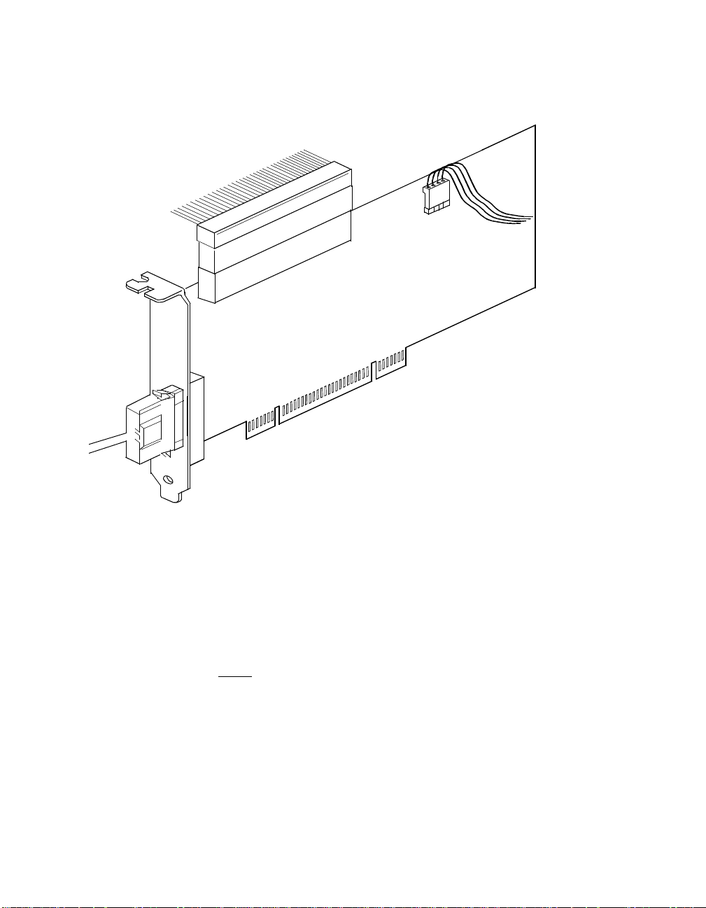
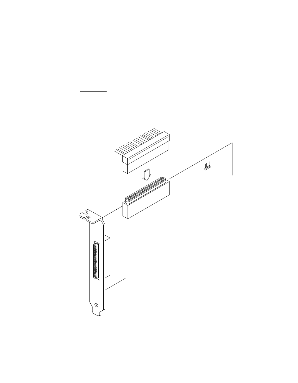
Figure 2.1 Hardware Connections for the SYM8953U Host Adapter
4.333 pc
44.25 pc
External
SCSI
Interface
J3
Internal
SCSI
Interface
J2
LED
Connector
J4
SYM8953U
J1 to PCI Mainboard
Step 7. Carefully insert edge connector J1 (see Figure 2.1) of the host
adapter into the PCI slot.
Make sure the edge connector is properly aligned before
pressing the board into place as shown in Figure 2.2.The
bracket around connector J3 should fit where you removed the
blank panel.
Note:
You may notice that the components on a PCI host adapter
face the opposite way from non-PCI adapter boards you
have in your system. This orientation is correct. The board
is keyed and will only go in one way.
Detailed Installation Procedure 2-5
48.583 pc
52.5 pc
Page 22
3.75 pc 10.25 pc 11.25 pc 38.25 pc
34.5 pc
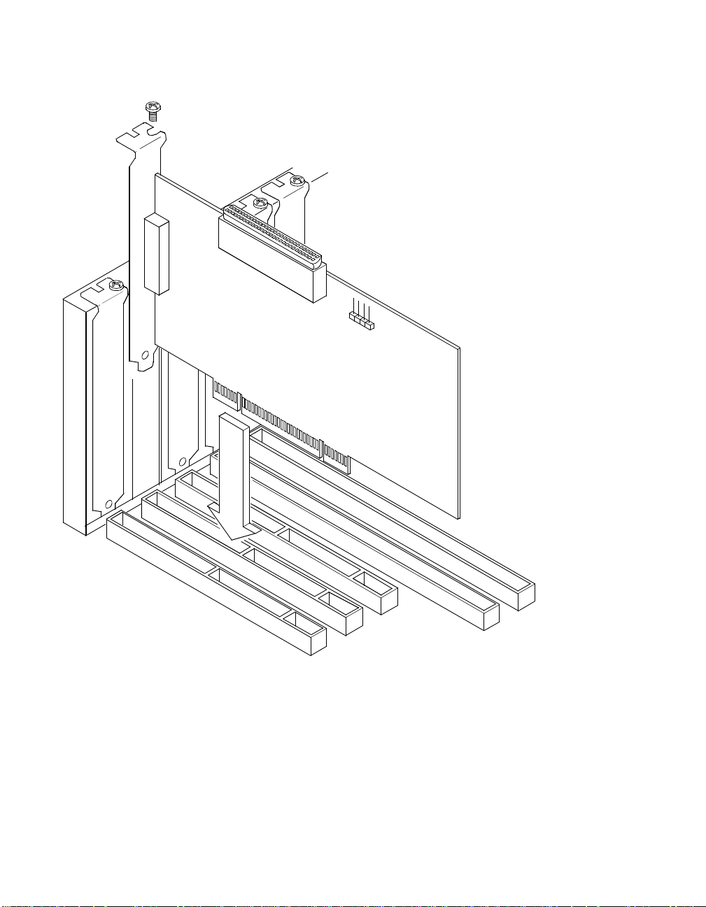
Figure 2.2 Inserting the Host Adapter
Bracket Screw
Bracket Surround
4.333 pc
44.25 pc
Step 8. Secure the board with the bracket screw (see Figure 2.2)before
making the internal and external SCSI bus connections.
48.583 pc
2-6 Installing the SYM8953U Host Adapter
52.5 pc
Page 23

3.75 pc 10.25 pc 11.25 pc 38.25 pc
34.5 pc
2.2.3 Connecting the SCSI Peripherals
4.333 pc
SCSI bus connections to the SYM8953U host adapter inside your
computercanbemadewithanunshielded68conductorUltraSCSIPVC
ribbon cable (see Figure 2.3).Theleadconnectedtopin1onthecable
is marked with a colored stripe. The connectors on this cable may also
be keyed to ensure proper pin-1 connection.
All external SCSI bus connections to the SYM8953U host adapter are
made with high quality shielded 68 conductor cables (see Figure 2.3).
The connectors on this cable are always keyed to ensure proper pin-1
connection.
44.25 pc
Note:
All the cables shown in Figure 2.3 are included in the
Symbios Adapter Board Kit for the SYM8953U host
adapter.
Table 2.1 SCSI Bus Widths and Speeds
STA Terms
SCSI-1 8 5
Fast SCSI 8 10
Fast Wide SCSI 16 20
Ultra SCSI 8 20
Wide Ultra SCSI 16 40
Ultra2 SCSI 8 40
Wide Ultra2 SCSI 16 80
Note: Absence of the word “Wide” means an 8-bit bus width. It is
acceptable to use the word “Narrow” to avoid ambiguity.
SCSI Bus
Width, Bits
SCSI Bus Speed
Maximum Data Rate,
Mbytes/s
You can connect up to eight SCSI, Fast SCSI, and Ultra SCSI devices
on a SE Ultra SCSI bus only if they are evenly spaced on a 1.5-meter
Ultra SCSI cable (0.19 m between devices).
Detailed Installation Procedure 2-7
48.583 pc
52.5 pc
Page 24

3.75 pc 10.25 pc 11.25 pc 38.25 pc
34.5 pc
You can connect up to four devices if they are evenly spaced on a
4.333 pc
3-meter Ultra SCSI cable (0.75 m between devices). Your SE SCSI bus
should not exceed 3 meters (total internal and external cable lengths),
even with fewer than four devices.
For L VD applications, you can connect up to 16 devices including the
host adapter if they are evenly spaced on a 12-meter Ultra SCSI cable
(0.19 m minimum between devices).
Table 2.2 SCSI Bus Lengths
44.25 pc
Maximum Bus Length, Meters
1
Maximum #
SE Differential LVD
of Devices
SCSI-1 6 25 12 8
Fast SCSI 3 25 12 8
Fast Wide SCSI 3 25 12 16
Ultra SCSI 1.5
Ultra SCSI 3
2
2
25 12 8
––4
Wide Ultra SCSI – 25 12 16
Wide Ultra SCSI 1.5 – – 8
Wide Ultra SCSI 3 – – 4
Ultra2 SCSI Note
Wide Ultra2 SCSI Note
3
3
Note
Note
3
3
12 8
12 16
1. This parameter may be exceeded in point-to-point and engineered
applications.
2. Additional spacing rules apply.
3. SE and high power differential are not defined at Ultra2 speeds.
2-8 Installing the SYM8953U Host Adapter
48.583 pc
52.5 pc
Page 25
3.75 pc 10.25 pc 11.25 pc 38.25 pc
34.5 pc
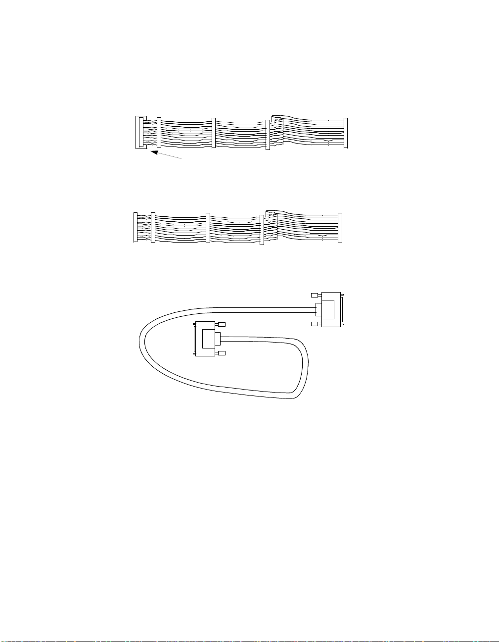
Figure 2.3 SCSI Cables
Terminated SCSI Cable for Internal Connections
(for use with nonterminated internal devices)
68-pin HD
Terminated End
SCSI Cable for Internal Connections
68-pin HD
SCSI Cable for External Connections
4.333 pc
44.25 pc
68-pin HD
48.583 pc
Detailed Installation Procedure 2-9
52.5 pc
Page 26
3.75 pc 10.25 pc 11.25 pc 38.25 pc
34.5 pc
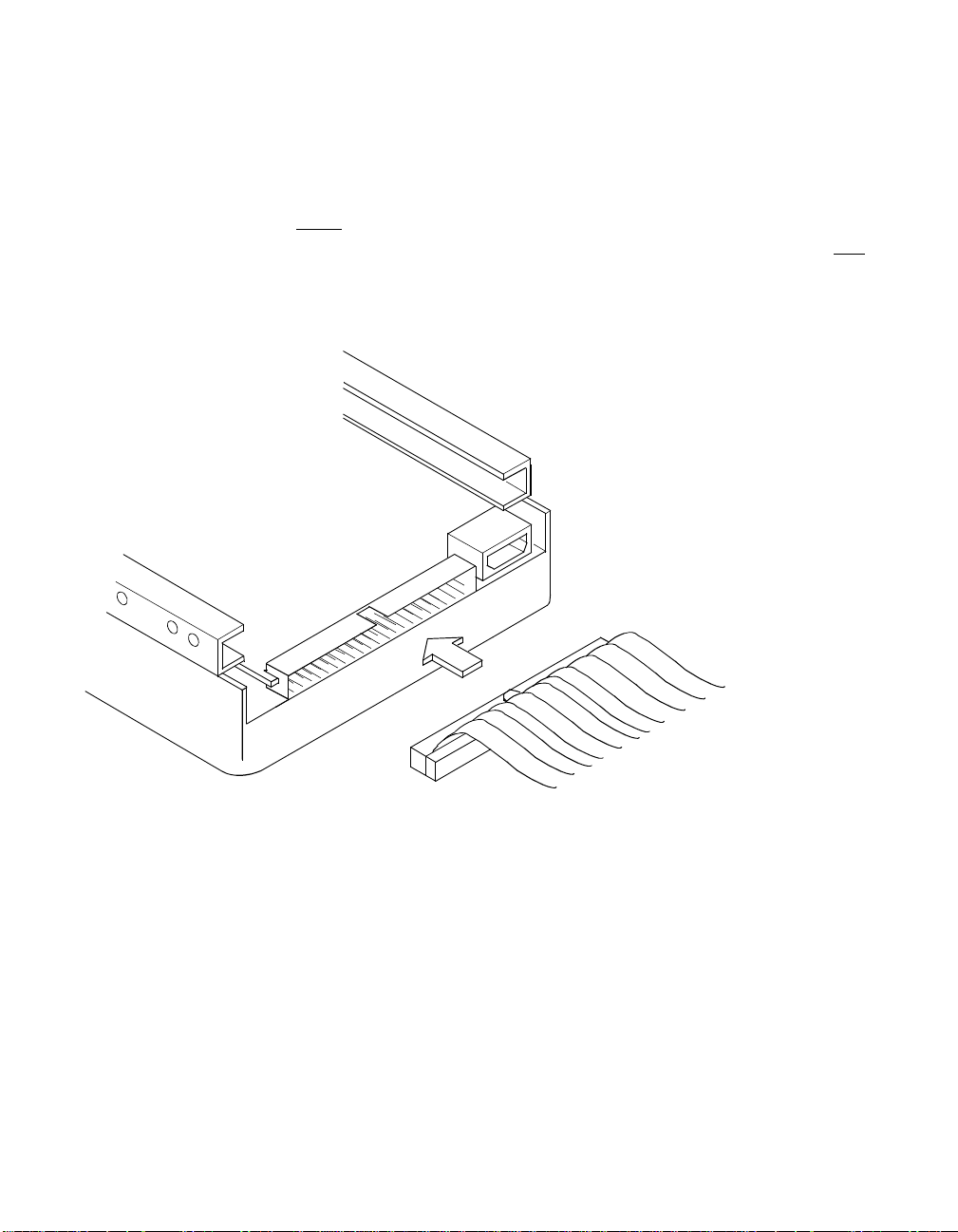
2.2.4 Making Internal SCSI Bus Connections
4.333 pc
This section provides step-by-step instructions about making internal
SCSI bus connections.
Step 1. Plug one end of the 68-pin internal SCSI ribbon cable into
connector J2 (see Figure 2.4).
44.25 pc
Important
: You must match pin 1 on this and all subsequent
connections.
Figure 2.4 Internal SCSI Ribbon Cable to Host Adapter
Connection
Internal
SCSI Interface
J2
2-10 Installing the SYM8953U Host Adapter
48.583 pc
52.5 pc
Page 27
3.75 pc 10.25 pc 11.25 pc 38.25 pc
34.5 pc
Step 2. If you have only two internal devices to connect, plug the other
4.333 pc
end of the internal SCSI ribbon cable into the SCSI connector
on your internal SCSI device. An example of this connection is
shown in Figure 2.5.
44.25 pc
Note:
For nonterminated internal SCSI devices, a terminated
cable will be required. This connector must be on the end
of the SCSI cable.
Figure 2.5 Internal SCSI Ribbon Cable to Internal SCSI Device Connection
Detailed Installation Procedure 2-11
48.583 pc
52.5 pc
Page 28

3.75 pc 10.25 pc 11.25 pc 38.25 pc
34.5 pc
If you have more than one internal device to connect, use an internal
4.333 pc
SCSI ribbon cable with the required number of connectors attached
along its length and proceed to the next step. If you have only one
internal device, proceed to page 2-14.
Step 3. Plug the cable into each additional device as needed.
An example of this type of chained connection is shown in
Figure 2.7. Make sure to match pin 1 on all connections.
Figure 2.6 Connecting Additional Internal SCSI Devices
44.25 pc
48.583 pc
2-12 Installing the SYM8953U Host Adapter
52.5 pc
Page 29

3.75 pc 10.25 pc 11.25 pc 38.25 pc
34.5 pc
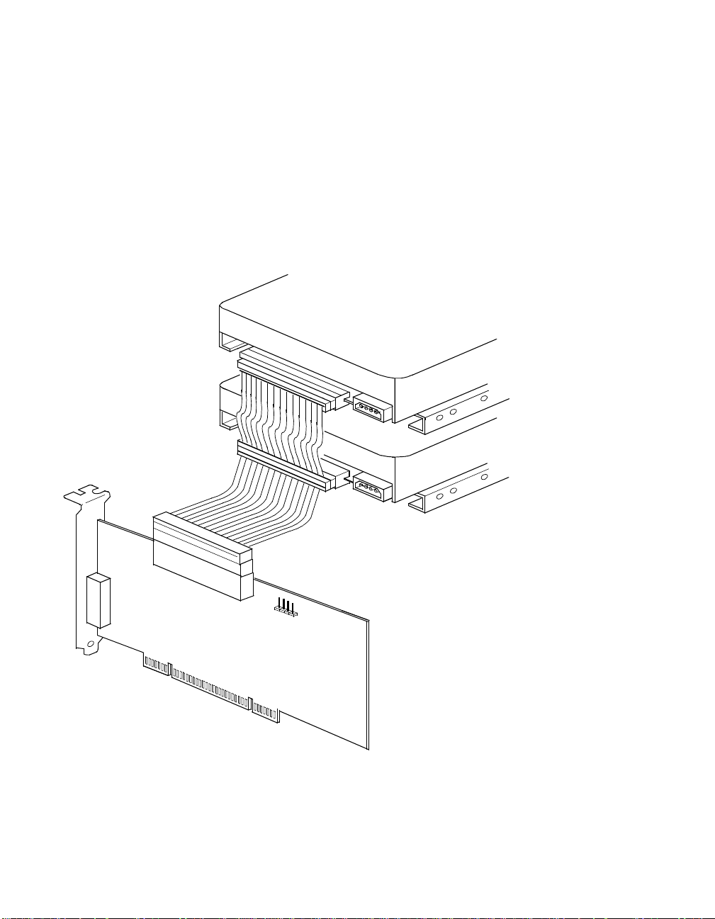
Figure 2.7 Multiple Internal SCSI Devices Chained Together
4.333 pc
44.25 pc
48.583 pc
Detailed Installation Procedure 2-13
52.5 pc
Page 30

3.75 pc 10.25 pc 11.25 pc 38.25 pc
34.5 pc
Most PC cabinets are designed with a front panel LED.
4.333 pc
Step 4. Connect the LED cable to connector J4 on the host adapter, as
shown in Figure 2.8.
When properly connected, the front panel LED lights when
there is activity on the SCSI bus.
Connector J4 is not keyed. The orientation of the LED cable
should not matter as long as all four pins are connected. If the
LED does not light during SCSI bus activity from this host
adapter, you may have to rotate the LED cable connector 180
°
on J4.
Figure 2.8 SCSI LED Connector
44.25 pc
LED
Connector
J4
Some LED cables have only two wires. In this case, place the
connector on one end or the other of J4. If the LED does not
light when there is SCSI activity, put the connector on the other
half of J4.
48.583 pc
2-14 Installing the SYM8953U Host Adapter
52.5 pc
Page 31

3.75 pc 10.25 pc 11.25 pc 38.25 pc
34.5 pc
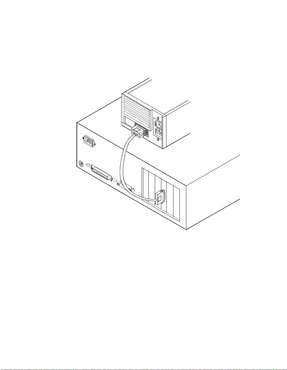
2.2.5 Making External SCSI Bus Connections
4.333 pc
This section provides step-by-step instructions about making external
SCSI bus connections. T o connect external SCSI devices to the
SYM8953U host adapter:
Step 1. Plug the 68-pin HD connector on one end of a shielded external
SCSI cable (see Figure 2.3) into the host adapter connector J3
(see Figure 2.1).
This connector is in the bracket attached to the back panel of
your computer. Figure 2.9 shows how this connection is made.
Figure 2.9 External Cable to Host Adapter
44.25 pc
HD Connector
48.583 pc
Detailed Installation Procedure 2-15
52.5 pc
Page 32
3.75 pc 10.25 pc 11.25 pc 38.25 pc
34.5 pc
Step 2. Plug the 68-pin connector on the other end of the shielded
4.333 pc
external SCSI cable into the SCSI connector on your external
SCSI device. An example of this connection is shown in
Figure 2.10.
Figure 2.10 External SCSI Device Cable
44.25 pc
HD Connectors
If this is the only external SCSI device on your system, proceed to
Section 2.2.6, “SCSI Bus Termination,” page 2-18 for termination
instructions. If you have multiple SCSI devices, proceed to the next page.
48.583 pc
2-16 Installing the SYM8953U Host Adapter
52.5 pc
Page 33
3.75 pc 10.25 pc 11.25 pc 38.25 pc
34.5 pc
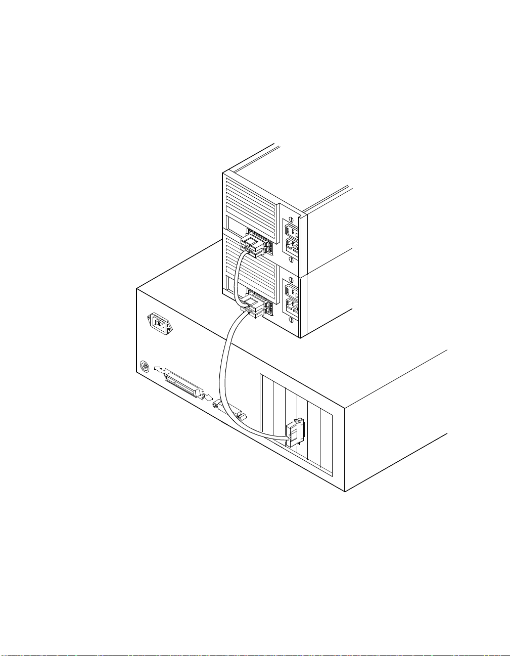
Step 3. Chain multiple devices together with shielded external SCSI
4.333 pc
cables.
An example of these chained connections is shown in
Figure 2.11.
Figure 2.11 Multiple External SCSI Devices Chained Together
44.25 pc
HD Connectors
After you have connected all of your internal and external devices,
proceed to Section 2.2.6, “SCSI Bus Termination.”
48.583 pc
Detailed Installation Procedure 2-17
52.5 pc
Page 34

3.75 pc 10.25 pc 11.25 pc 38.25 pc
34.5 pc
2.2.6 SCSI Bus Termination
4.333 pc
The devices making up the SCSI bus are connected serially (chained
together) with SCSI cables. The first and last physical SCSI devices
connected on the ends of the SCSI bus must have their terminators
active. All other SCSI devices on the bus must have their terminators
removed or disabled. Remember that the SYM8953U host adapter is
also on the SCSI bus—its termination is automatically enabled when it is
connected to the end of the bus.
44.25 pc
Important:
To utilize Ultra2 SCSI performance, you must only have
LVD devices on the bus. Do not mix any SE devices with
LVD devices or the entire bus will drop to SE, limiting bus
performance to Ultra SCSI levels.
The peripheral device terminators are usually set with jumpers, resistor
modules, or with a switch on the peripheral. Refer to the peripheral
manufacturer’s instructions and to the user’s manual for your computer
for information on how to identify the terminator type/setting for each
device and how to set/change it.
Caution:
The autoenable/disable sensing feature on the SYM8953U
may enable termination erroneously if it is directly cabled to
another SCSI device or host adapter using the same
sensing method. The SYM8953U senses the presence of
SCSI devices by detecting the ground signal on conductor
50 of the SCSI cable.
The SYM8953U automatically controls SCSI bus termination for three
different bus configurations, depending on how it is connected (see
Figure 2.1). The three bus configurations are:
• Section 2.2.6.1, “Internal Bus Connections”
• Section 2.2.6.2, “External Bus Connections”
• Section 2.2.6.3, “Internal and External Bus Connections”
Termination on the SYM8953U host adapter for these three different bus
configurations is discussed below.
2-18 Installing the SYM8953U Host Adapter
48.583 pc
52.5 pc
Page 35
3.75 pc 10.25 pc 11.25 pc 38.25 pc
34.5 pc
2.2.6.1 Internal Bus Connections
4.333 pc
If you have only internal SCSI device connections to your host adapter,
you must terminate the last internal device on the SCSI bus. You must
disable the terminators on all other devices. Termination on your host
adapter is automatically enabled in this case.
Figure 2.12 shows an example of how termination is determined for this
SCSI bus configuration.
Figure 2.12 Internal SCSI Device Termination
Last Device on
Bus - Terminators
Enabled
44.25 pc
Does not end Bus Terminators Disabled
Host Adapter
Automatically
Terminated
48.583 pc
Detailed Installation Procedure 2-19
52.5 pc
Page 36

3.75 pc 10.25 pc 11.25 pc 38.25 pc
34.5 pc
2.2.6.2 External Bus Connections
4.333 pc
If you have only external SCSI device connections to your host adapter,
you must terminate the last external device on the SCSI bus. You must
disable the terminators on all other devices. Termination on the host
adapter is automatically enabled in this case.
Figure 2.13 shows an example of how termination is determined for this
SCSI bus configuration.
Figure 2.13 External SCSI Device Termination
Last Device
on Bus Terminators
Enabled
44.25 pc
Does not
end Bus Terminators
Disabled
Host Adapter
Automatically
Terminated
48.583 pc
2-20 Installing the SYM8953U Host Adapter
52.5 pc
Page 37

3.75 pc 10.25 pc 11.25 pc 38.25 pc
34.5 pc
2.2.6.3 Internal and External Bus Connections
4.333 pc
If you have both internal and external SCSI device connections to your
host adapter, you must terminate the last internal and last external
devices on the SCSI bus. You must also disable the termination on all
other devices. Termination on the host adapter is automatically disabled
in this case.
Figure 2.14 shows an example of how termination is determined for this
SCSI bus configuration.
Figure 2.14 Internal and External SCSI Device Termination
Last device on Bus Terminators Enabled
Does not end Bus Terminators Disabled
44.25 pc
Host Adapter Termination
Automatically Disabled
Do not end Bus Terminators Disabled
Last Device on Bus Terminators Enabled
48.583 pc
Detailed Installation Procedure 2-21
52.5 pc
Page 38

3.75 pc 10.25 pc 11.25 pc 38.25 pc
34.5 pc
2.2.7 Setting SCSI IDs
You must set each SCSI device and the host adapter to a separate SCSI
ID 0 through 15. SCSI ID 7 is the preset host adapter setting, giving it
the highest priority on the SCSI bus. If you plan to boot your computer
from a SCSI hard disk drive on the SCSI bus, that drive should have the
lowest SCSI ID on the bus. Typically, SCSI ID 0 is used; however, for
system performance optimization, an ID other than 0 (zero) can be used.
Chapter 3, “Configuring the SYM8953U Host Adapter” explains how to
set the host adapter ID using the Symbios SCSI BIOS Configuration
Utility.
The peripheral device SCSI IDs are usually set with jumpers or with a
switch on the peripheral. Refer to the peripheral manufacturer’s
instructions and to the user’s manual for your computer to determine the
ID of each device and how to change it.
: Yo u must not have any duplication of SCSI IDs on a SCSI
Note
bus.
Step 1. Determine the SCSI ID of each device on the SCSI bus. Note
44.25 pc
Step 2. Make any necessary changes to the SCSI IDs to eliminate
any duplications.
duplicates and record the IDs for future reference.
4.333 pc
Table 2.3 is provided as a place to keep this record.
2-22 Installing the SYM8953U Host Adapter
48.583 pc
52.5 pc
Page 39

3.75 pc 10.25 pc 11.25 pc 38.25 pc
34.5 pc
4.333 pc
Table 2.3 SCSI ID Record
SCSI ID SCSI Device
15
14
13
12
11
10
9
8
7 SYM8953U Host Adapter (default)
6
44.25 pc
5
4
3
2
1
0
48.583 pc
Detailed Installation Procedure 2-23
52.5 pc
Page 40
3.75 pc 10.25 pc 11.25 pc 38.25 pc
34.5 pc
4.333 pc
2.3 Completing the Installation
Before replacing the cover on your computer, review this installation
procedure check list. This can save you effort later.
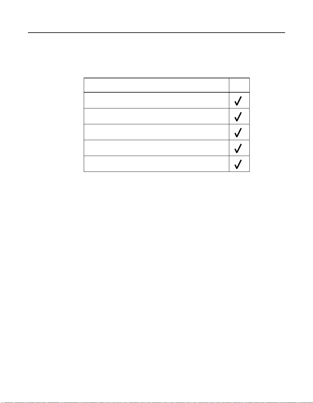
Verify Installation Procedures Done
Host adapter connection in PCI bus slot secure
Internal SCSI bus connections secure (pin-1 continuity)
External SCSI bus connections secure
Proper SCSI bus termination established
Unique SCSI IDs set and recorded for each device
Step 1. Replace the cabinet cover on your computer.
44.25 pc
Step 2. Plug in all power cords.
Step 3. Switch power on to all devices and your computer.
Step 4. Wait for your computer to boot up.
Step 5. To change the configuration of the host adapter, see Chapter 3,
“Configuring the SYM8953U Host Adapter”.
Step 6. Load the software and drivers suitable to your application and
system.
Refer to the Symbios PCI SCSI Device Management System
SDMS 4.0 User’s Guide or the guide for the software you plan
to use.
48.583 pc
2-24 Installing the SYM8953U Host Adapter
52.5 pc
Page 41

3.75 pc 10.25 pc 11.25 pc 38.25 pc
34.5 pc
4.333 pc
Chapter 3
Configuring the SYM8953U
Host Adapter
12 pc
12.938 pc
This chapter describes configuring the SYM8953U Host Adapter and
includes these topics:
• Section 3.1, “Overview of the SCSI BIOS Configuration Utility,”
page 3-1
• Section 3.2, “The Symbios SCSI BIOS Configuration Utility Menus,”
page 3-3
3.1 Overview of the SCSI BIOS Configuration Utility
13.851 pc
34.732 pc
The SYM8953U Host Adaptor is loaded with Symbios SCSI BIOS and
Configuration Utility Version 4.15 (or greater). This chapter describes the
process you need to follow to change configuration settings on your
board.
The SDMS SCSI BIOS provides support for the BIOS Boot Specification
(BBS), which allows you to choose which device to boot from by
selecting the priority.
To use this feature, the system BIOS must also be compatible with the
BBS. If your system supports the BBS, then you will use the system
BIOS setup menu to select the boot and drive order. In the system BIOS
setup, the Boot Connection Devices menu appears with a list of available
boot options.Use that menu to select the device and rearrange the order.
Then exit to continue the boot process.
In most cases you should not need to change the default configuration
of the host adapter. You may decide to alter these default values if there
is a conflict between device settings or if you need to optimize system
performance.
48.583 pc
Symbios SYM8953U PCI to Ultra2 SCSI Host Adapter 3-1
52.5 pc
Page 42

3.75 pc 10.25 pc 11.25 pc 38.25 pc
34.5 pc
There are four sets of configurations you can change. You make changes
4.333 pc
on subordinate menus called from the Main Menu, which is opened when
you start the Configuration Menu. The subordinate menus are listed
below.
• Adapter properties
• Device properties
• Adapter boot list
• Global properties
All these properties are controlled by menus you access through the
configuration utility Main Menu. The Main Menu also gives an overview
of some properties of installed Symbios host adapter boards.
3.1.1 Starting the Configuration Utility
You can see the version number of your Symbios SCSI BIOS in a banner
displayed on your computer monitor during boot. If the utility is available,
the following message also appears on your monitor:
44.25 pc
Press Ctrl-C to start Symbios Configuration Utility.. .
This message remains on your screen for about five seconds, giving you
time to start the utility. If you decide to press “Ctrl-C,” the message
changes to:
Please wait, invoking Symbios Configuration Utility...
After a brief pause, your computer monitor displays the Main Menu of the
Symbios SCSI BIOS Configuration Utility.
These messages may appear during the boot process:
• “Adapter removed from boot order, parameters will be
updated accordingly” appears when an adapter is removed from
the system or relocated behind a PCI bridge.
• “Configuratio n data invalid, saving default
configuration !” appears if none of the information in the NVRAM
is valid.
• “Found SCSI Controller not in following Boot Order List,
to Add: Press Ctrl-C to start Symbios Configuration
48.583 pc
3-2 Configuring the SYM8953U Host Adapter
52.5 pc
Page 43

3.75 pc 10.25 pc 11.25 pc 38.25 pc
34.5 pc
Utility...” appears when less than four adapters are in the boot
4.333 pc
order and more adapters exist than are shown.
NonVolatile Random Access Memory (NVRAM) is available on the
SYM8953U Host Adapter. Changes can be made and stored using this
menu driven utility.
44.25 pc
Important
: This utility is a powerfultool.If, while using it, you somehow
disable all of your controllers you can recover. Pressing
Ctrl-E after memory initialization during a reboot allows you
to re-enable and reconfigure.
Note:
Not all devices detected by the Configuration Utility can be
controlled by the BIOS. Devices such as tape drives and
scanners require that a device driver specific to that
peripheral be loaded. This device driver is provided by the
device manufacturer.
3.1.2 Exiting the SCSI BIOS Configuration Utility
Since most changes only take effect after the system reboots, you must
exit properly from the Configuration Utility. The proper exit technique is
described in Section 3.2.7, “Exit Menu,” page 3-20. It also describes
exiting the subordinate menus.
3.2 The Symbios SCSI BIOS Configuration Utility Menus
This chapter describes the menu system of the Symbios SCSI BIOS
Configuration Menu System.
3.2.1 Using the Menus
You make your configuration changes in the main area of the menu. As
in the example menus, it is lighter in color than the header or footer
areas. The commands you use to make changes are shown in the footer
area and described in Table 3.1. Settings with black text can be changed,
settings with white text cannot. This is true regardless of whether the
Color or Mono setting is chosen in the Global Properties Menu
(Figure 3.6), described in detail later.
The Symbios SCSI BIOS Configuration Utility Menus 3-3
48.583 pc
52.5 pc
Page 44

3.75 pc 10.25 pc 11.25 pc 38.25 pc
34.5 pc
4.333 pc
Table 3.1 Configuration Commands
Command Description
44.25 pc
F1 = Help Provides context s ensitive help for the cursor
resident field.
Arrow Keys = Select Item Move the cursor up, down, left, or right.
+/– = Change [Item] Changes items with values in [ ] brackets. Only the
numeric keypad ‘+’ and ‘–’ are enabled. When
pressed, they toggle modifiable field to its next
relative value. ‘+’ toggles the value up and ‘–’
toggles the value down.
Esc = Abort/Exit Aborts the current context operation and/or exits
the current screen. This option calls an Exit menu,
described further in Section 3.2.7.
Home/End = Select Item Moves the cursor to the start/end of a scrollable
field.
Enter = Execute <Item> Executes options with values in < > brackets. Press
Enter to execute the field’s associated function.
F2 = Menu Sets cursor context to the Optional Menu area.
Select a menu item and press Enter. This option is
only available from the Main and Adapter
Properties menus.
3.2.2 Main Menu
When you start the Symbios SCSI BIOS Configuration Utility, the Main
Menu, shown in Figure 3.1, appears. This menu displays a list of installed
Symbios PCI to SCSI host adapters, information about each of them, and
a series of other menu options. This list displays up to four boards.
At the opening menu, the cursor is on one of the listed adapters. If you
need to change the configuration of an adapter, move to the board you
want to change with the arrow keys and press Enter. This calls the menu
described in detail in Section 3.2.3, “Adapter Properties Menu.” From this
menu you can view and/or change the current settings for that adapter
and the SCSI devices attached to it. You can select an adapter only if
Current Status is “On.” Changes are possible since NVRAM is present
on this host adapter.
3-4 Configuring the SYM8953U Host Adapter
48.583 pc
52.5 pc
Page 45

3.75 pc 10.25 pc 11.25 pc 38.25 pc
34.5 pc
Figure 3.1 is an example of the Configuration Utilities Main Menu. Table
4.333 pc
3.2 lists the Main Menu fields and their descriptions.
Figure 3.1 Main Menu
Symbios PCI SCSI Configuration Utility Version PCI 4.15.00
<Boot Adapter List> <Global Properties>
SYM53C8XX Host Bus Adapters
44.25 pc
Adapter PCI
Bus
Dev/
Func
Port
Number
IRQ NVM Boot
Order
LSI Logic
Control
<SYM53C895A 0 98> FC00 9 Ye s 2 Enabled
<SYM53C896 0 88> F800 10 Yes 3 Disabled
<SYM53C896 0 58> E400 11 Yes 1 Enabled
F1 = Help ↑↓→← = Select Item -/+ = [Change Item]
Esc = Abort/Exit Home/End = Scroll Enter = Execute <Item>
F2 = Menu
Table 3.2 Main Menu Fields and Descriptions
Fields Descriptions
Adapter Indicates the specific SYM53C8XX Host Adapter.
PCI Bus Indicates the PCI Bus number (range 0x00–0xFF,
0–255 decimal) assigned by the system BIOS to an
adapter.
The Symbios SCSI BIOS Configuration Utility Menus 3-5
48.583 pc
52.5 pc
Page 46

3.75 pc 10.25 pc 11.25 pc 38.25 pc
34.5 pc
Table 3.2 Main Menu Fields and Descriptions (Cont.)
Fields Descriptions
4.333 pc
44.25 pc
Dev/Func Indicates the PCI Device/Function assigned by the
system BIOS to an adapter.
The 8-bit value is mapped as follows:
Bit#76543210
Bits [7:3]: Device (range 0x00–0x1F, 0–31 decimal)
Bits [2:0]: Function (range 0–7)
Port Number Indicates which I/O port communicates with an adapter,
as assigned by the system BIOS.
IRQ Indicates the Interrupt Request Line used by an adapter,
as assigned by the system BIOS.
NVM Indicates whether an adapter has NVM (NonVolatile
Memory) associated withit. An adapter's configurationis
stored in its associated NVM. NVM can refer to NVRAM
that is resident on a host adapter or to system
NonVolatile Storage (NVS).
Boot Order Indicates the relative boot order (0 to 3) of an adapter.
The Symbios SCSI BIOS traverses up to four adapters
in the specified order in search of bootable media. To
modify this field, access the Boot Adapter List Menu.
LSI Logic Indicates whether an adapter is eligible for LSI Logic
Symbios software control or is reserved for control by
non-Symbios software.
3.2.3 Adapter Properties Menu
The Adapter Properties menu allows you to view and modify adapter
settings and as well as the SCSI devices connected to it. It also provides
access to an adapter's device settings. To display this menu, select a
device in the Adapter field on the Main Menu and press Enter. After
pressing Enter, the following message flashes before the menu appears:
“Initializing the adapters, reading for non-volatile
settings, and scanning for devices.....” After a few seconds the
menu appears. Figure 3.2 provides an example of the Adapter Properties
menu.
3-6 Configuring the SYM8953U Host Adapter
48.583 pc
52.5 pc
Page 47

3.75 pc 10.25 pc 11.25 pc 38.25 pc
34.5 pc
4.333 pc
Figure 3.2 Adapter Properties Menu
Symbios PCI SCSI Configuration Utility Version PCI 4.15.00
Adapter Properties SYM53C895A 0A0
<Device Properties>
SCSI Parity [Yes]
Host SCSI ID [7]
SCSI Bus Scan Order [Low to High (0.Max)]
44.25 pc
Removable Media
[None]
Support
CHS Mapping [SCSI Plug and Play Mapping]
Spinup Delay (Secs) [2]
Secondary Cluster
[No]
Server
Termination Control [Auto]
<Restore Defaults>
F1 = Help ↑↓→← = Select Item -/+ = [Change Item]
Esc = Abort/Exit Home/End = Scroll Enter = Execute <Item>
The Symbios SCSI BIOS Configuration Utility Menus 3-7
48.583 pc
52.5 pc
Page 48

3.75 pc 10.25 pc 11.25 pc 38.25 pc
34.5 pc
Table 3.3 lists the fields you can access and their descriptions.
Note
: If the field displays in black text it is available for changes.
4.333 pc
If it displays in white text, it is not available.
Table 3.3 Adapter Properties Fields and Descriptions
44.25 pc
Field Field Type
Descriptions
[Value]
Device Proper ties Executable Select this option and press Enter to view and modify
device properties.
SCSI Parity Configuration
[Yes/No]
Indicates whether SCSI parity is enabled for an
adapter. When disabled, it is also necessary to
disabledisconnects for all devices, as parity checking
for the reselection phase is not disabled. If a
non-parity generating device disconnects, its
operationwillnever complete because thereselection
fails due to parity error.
Host SCSI ID Configuration
[0to7/0to15]
Indicates the SCSI identifier of an adapter. It is
recommended that this field be set to the highest
priority SCSI identifier, which is 7.
SCSI Bus Scan Order Configuration
[Low to High (0 to
Max)/HightoLow
(Max to 0)]
Removable Media
Support
Configuration
[None / Boot Drive
Only / With Media
Installed]
Indicates the order in which to scan SCSI identifiers
on an adapter. Changing this item will affect drive
letter assignment(s) if more than one device i s
attached to an adapter.
Specifies the removable media support option for an
adapter. Removable media support only applies to
devices that report themselves as a hard drive. It
does not apply to CD-ROM devices or Magnetic
Optical devices.
None indicates no removable media support whether
the drive is selected as first (BBS), or is first in the
scan order (non-BBS).
Boot Drive Only provides removable media support
for a removable hard drive if it is first in the scan
order.
With Media Installed provides removable m edia
support regardless of the drive number assignment.
3-8 Configuring the SYM8953U Host Adapter
48.583 pc
52.5 pc
Page 49

3.75 pc 10.25 pc 11.25 pc 38.25 pc
34.5 pc
Table 3.3 Adapter Properties Fields and Descriptions (Cont.)
4.333 pc
44.25 pc
Field Field Type
[Value]
CHS Mapping Configuration
[SCSI Plug and Play
Mapping / Alternate
CHS Mapping]
Spinup Delay
(Seconds)
Secondary Cluster
Server
Configuration
[1 to 15]
Configuration
[Yes / No]
Descriptions
Defines how the Cylinder Head Sector (CHS) values
are mapped onto a disk without pre-existing partition
information.
SCSI Plug and Play Mapping automatically
determines the most efficient and compatible
mapping.
Alternate CHS Mapping utilizes an alternate, possibly
less efficientmapping that may berequired if a device
is moved between adapters from different vendors.
Caution: Neither of these optionshasany effect after
a disk has been partitioned using the FDISK
command. The FDISK utility is a tool that the user can
use to delete partition entries, one or all of them. If all
partition entries are deleted, it is necessary to reboot
to clear memory or the old partitioning data will be
reused, thus nullifying the previous operation. Use
care to ensure that the correct disk is the target of an
FDISK command.
Indicates the delay in seconds between spinups of
devices attached to an adapter. Staggered spinups
balance the total electrical currentloadonthe system
during boot. The default value is 2 seconds.
Indicates whether an adapter has one or more
devices attached that are shared with one or more
other adapters and therefore, the Symbios SCSI
BIOS should avoid SCSI bus resets as much as
possible.
This option allows the user to enable an adapter to
join a cluster of adapters without doing any SCSI bus
resets. This is a requirement for Microsoft Cluster
Server. The default value is No with an alternate
option of Yes.
Termination Control Configuration
[Auto / Off]
If available, thefieldindicates whether an adapterhas
automatic termination control.
Auto means that the adapter automatically
determines whether it should enable or disable its
termination. Auto is the default state unless
termination is done manually, in which case, the
configuration is Off.
<Restore Defaults> Executable Press Enter to obtain default settings.
The Symbios SCSI BIOS Configuration Utility Menus 3-9
48.583 pc
52.5 pc
Page 50

3.75 pc 10.25 pc 11.25 pc 38.25 pc
34.5 pc
3.2.4 Device Properties Menu
4.333 pc
The Device Properties Menu allows you to view and update individual
device settings for an adapter. Changing a setting for the host device (for
example, SCSI ID 7) changes the setting for all devices. The number of
fields displayed requires the menu to scroll left/right in order to display
the information. When accessing this menu online, use the Home/End
keys to scroll to columns currently not displayed. The scroll indicator on
the bottom of the menu shows where the cursor is relative to the first and
last columns. The example for the Device Properties Menu is split
(Figure 3.3 and Figure 3.4) due to the width of its multiple fields/columns.
44.25 pc
48.583 pc
3-10 Configuring the SYM8953U Host Adapter
52.5 pc
Page 51

3.75 pc 10.25 pc 11.25 pc 38.25 pc
34.5 pc
4.333 pc
Figure 3.3 Device Properties Menu (Left Half)
Symbios PCI SCSI Configuration Utility Version PCI 4.15.00
Device Properties SYM53C895A 0 A0
44.25 pc
SCSI
ID
Device Identifier Sync
Rate
Data
Width
ScanIDScan
LUNs>0
Disconnect
0 Quantum Viking 4.5 [20] [16] [Yes] [Yes] [O n]
1 Quantum Viking 4.5 [20] [16] [Yes] [Yes] [O n]
2 Quantum Viking 4.5 [20] [16] [Yes] [Yes] [O n]
3 Quantum Viking 4.5 [20] [16] [Yes] [Yes] [O n]
4 Quantum Viking 4.5 [20] [16] [Yes] [Yes] [O n]
5 Quantum Viking 4.5 [20] [16] [Yes] [Yes] [O n]
6 - [20] [16] [Yes] [Yes] [On]
7 SYM53C895A [20] [16] [Yes] [Yes] [On]
8 - [20] [16] [Yes] [Yes] [On]
9 - [20] [16] [Yes] [Yes] [On]
10 - [20] [16] [Yes] [Yes] [On]
11 - [20] [16] [Yes] [Yes] [On]
12 - [20] [16] [Yes] [Yes] [On]
13 - [20] [16] [Yes] [Yes] [On]
14 - [20] [16] [Yes] [Yes] [On]
15 - [20] [16] [Yes] [Yes] [On]
<<
F1 = Help ↑↓→← = Select Item -/+ = [Change Item]
Esc = Abort/Exit Home/End = Scroll Enter = Execute <Item>
The Symbios SCSI BIOS Configuration Utility Menus 3-11
48.583 pc
52.5 pc
Page 52

3.75 pc 10.25 pc 11.25 pc 38.25 pc
34.5 pc
Figure 3.4 Device Properties Menu (Right Half)
4.333 pc
Symbios PCI SCSI Configuration Utility Version PCI 4.15.00
Device Properties SYM53C895A 0 A0
44.25 pc
SCSIIDDevice Identifier SCSI
Timeout
Queue
Tags
Boot
Choice
Format Verify Restore
Defaults
0 Quantum Viking 4.5 <10> [On] [No] [Format] [Verif y] <Defau lts>
1 Quantum Viking 4.5 <10> [On] [No] [Format] [Verif y] <Defau lts>
2 Quantum Viking 4.5 <10> [On] [No] [Format] [Verif y] <Defau lts>
3 Quantum Viking 4.5 <10> [On] [No] [Format] [Verif y] <Defau lts>
4 Quantum Viking 4.5 <10> [On] [No] [Format] [Verif y] <Defau lts>
5 Quantum Viking 4.5 <10> [On] [No] [Format] [Verif y] <Defau lts>
6 - <10> [On] [No] [Format] [Verify] <Default s>
7 SYM53C895A <10> [On] [No] [Format] [Verif y] <Defau lts>
8 - <10> [On] [No] [Format] [Verify] <Default s>
9 - <10> [On] [No] [Format] [Verify] <Default s>
10 - <10> [On] [No] [Format] [Verif y] <Defau lts>
11 - <10> [On] [No] [Format] [Verif y] <Defau lts>
12 - <10> [On] [No] [Format] [Verif y] <Defau lts>
13 - <10> [On] [No] [Format] [Verif y] <Defau lts>
14 - <10> [On] [No] [Format] [Verif y] <Defau lts>
15 - <10> [On] [No] [Format] [Verif y] <Defau lts>
>>
F1 = Help ↑↓→← = Select Item -/+ = [Change Item]
Esc = Abort/Exit Home/End = Scroll Enter = Execute <Item>
3-12 Configuring the SYM8953U Host Adapter
48.583 pc
52.5 pc
Page 53

3.75 pc 10.25 pc 11.25 pc 38.25 pc
34.5 pc
Table 3.4 lists the fields and their descriptions.
4.333 pc
Table 3.4 Device Properties Fields and Descriptions
44.25 pc
Field Field Type
Description
[Value]
SCSI ID Information Device’s SCSI Identifier.
Device Identifier Information Indicates the ASCII device identifier string, as extracted
from the device’s inquiry data.
Sync Rate Configuration
[0 / 5 / 10 / 20 / 40]
Indicates themaximum synchronousdata transfer ratein
mega transfers per second.
Mega Xfers Data Width Data Width Synch
per second = 8 bits = 16 bits Period (ns)
0 = Asynch 0 = Asynch 0 = Asynch 0 = Asynch
5 5 10 200
10 10 20 100
20 20 40 50
40 40 80 25
Data Width Configuration
Maximum data width in bits.
[8 / 16]
Scan ID Configuration
[Yes / No]
Indicates whether to scan for this SCSI identifier at boot
time. Utilizing this setting allows you to ignore a device.
This decreases boot time by disabling inquiry of unused
SCSI identifiers.
SetthisoptiontoNoifthereisadevicethatyoudonot
want to be available to the system. Also, on a bus with
only a few devices attached, the user can speed up boot
time by changing this setting to No for all unused SCSI
IDs.
Scan LUNs > 0 Configuration
[Yes / No]
The Symbios SCSI BIOS Configuration Utility Menus 3-13
Indicates whether to scan for LUNs greater than zero for
a device. LUN 0 is alwaysqueried. This option should be
used if a multi-LUN device responds to unoccupied
LUNs or if it is desired to reduce the visibility of a
multi-LUNdevicetoLUN0only.
SetthisoptiontoNoifyouhaveproblemswithadevice
that responds to all LUNs whether they are occupied or
not. Also, if a SCSI device with multiple LUNs exists on
your system but you do not want all of those LUNs to be
available to the system, then set this option to No. This
will limit the scan to LUN 0.
48.583 pc
52.5 pc
Page 54

3.75 pc 10.25 pc 11.25 pc 38.25 pc
34.5 pc
Table 3.4 Device Properties Fields and Descriptions (Cont.)
4.333 pc
44.25 pc
Field Field Type
[Value]
Disconnect Configuration
[On / Off]
SCSI Time-out Executable
[0–9999]
Queue Tags Configuration
[On / Off]
Boot Choice Configuration
[Yes / No]
Description
Indicates whether to allow a device to disconnect during
SCSI operations. Some (usually newer) devices run
faster with disconnect enabled, while some (usually
older) devices run faster with disconnect disabled.
Indicates the maximum allowable time for completion of
a SCSI operation in seconds.
Since time-outs provide a safeguard that allows the
system to recover should an operation fail, it is
recommended that a value greater than zero be used. A
value of zero allows unlimited time for an operation to
completeandcould result in thesystem hanging (waiting
forever) should an operation fail.
Note: This field is executable and must be selected with
the Enter key. You also input the new value with the
number keys from the keyboard, not the number pad.
This field indicates whether to allow the use of queue
tags for a device. Currently the BIOS does not use
queue tags. This item specifies queue tag control to
higher level device drivers.
Indicates whether this device can be selected as the
boot device. This option is only applicable to devices
attached to adapter number zero in the boot list on
non-BBS systems. It provides primitive BBS flexibility to
non-BBS systems.
Format Executable Allows low-level formatting on a disk drive, if enabled.
Low-level formatting will completely and irreversibly
erase all data on the drive. To low level format a device,
select the device from the menu and use the arrow keys
to move the cursor to the Format column. Press Enter.
Note: Formatting will default the drive to a 512-byte
sector size even if the drive had previously been
formatted to another sector size.
Verify Executable Allows verification of all sectors on a device and
reassigns defective Logical Block Addresses, if enabled.
To verifyall sectors, select the devicefrom the menu and
usethearrowkeystomovethecursortotheVerify
column. Press Enter.
<Restore Defaults> Executable Press Enter to obtain default settings.
3-14 Configuring the SYM8953U Host Adapter
48.583 pc
52.5 pc
Page 55

3.75 pc 10.25 pc 11.25 pc 38.25 pc
34.5 pc
3.2.5 Boot Adapter List Menu
The Boot Adapter List Menu specifies the order in which adapters boot
when more than one Symbios adapter is in a system. Up to four of the
total adapters in a system can be selected as bootable. This menu may
also list additional adapters in your system that are not bootable. As
many as 256 adapters can be listed. To control a Boot Volume, only one
of the four “active” controllers can be used.
To select this menu:
1. Press F2 while on the Main Menu to move the cursor to the Optional
Menu area.
2. Move the cursor to Boot Adapter List with the arrow keys.
3. Press Enter.
Adapters can be added or deleted using this menu. Use the arrow keys
to move the cursor to the lower list, the adapter select list, to add or
remove an adapter. To add an adapter to the boot list, press the Insert
key while on the Boot Adapter List. Use the arrow keys to select the
44.25 pc
desired adapter and press Enter to add it to the end of the Boot Adapter
List. To change the configuration of the adapter, use the arrow keys to
move to the configuration you want to alter.
4.333 pc
To remove an adapter from the boot list, press the Delete key while on
the desired adapter in the Boot Adapter List.
Note:
If a new device is added after this utility loads, it can only
be seen in the adapter configuration section of this utility
after a reboot. You must exit the utility and restart it for the
new device to be seen by the Configuration Utility.
The Symbios SCSI BIOS Configuration Utility Menus 3-15
48.583 pc
52.5 pc
Page 56

3.75 pc 10.25 pc 11.25 pc 38.25 pc
34.5 pc
Figure 3.5 provides an example of the Boot Adapter List Menu.
4.333 pc
Figure 3.5 Boot Adapter List Menu
Symbios PCI SCSI Configuration Utility Version PCI 4.15.00
Boot Adapter List
Insert = Add an adapter Delete = Remove an adapter
44.25 pc
Adapter PCI
Bus
Dev/
Func
Boot
Order
Current
Status
Next
Boot
<SYM53C895A 0 98> [2] Off [On]
<SYM53C896 0 88> [1] On [Off]
<SYM53C896 0 58> [0] On [On
Hit Insert to select an adapter from this list.
<SYM53C895A 0 98>
<SYM53C896 0 88>
<SYM53C896 0 58>
F1 = Help ↑↓→← = Select Item -/+ =[Change Item]
Esc = Abort/Exit Home/End = Scroll Enter=Execute <Item>
3-16 Configuring the SYM8953U Host Adapter
48.583 pc
52.5 pc
Page 57

3.75 pc 10.25 pc 11.25 pc 38.25 pc
34.5 pc
Table 3.5 lists the fields on this menu and their descriptions.
4.333 pc
Table 3.5 Boot Adapter List Fields and Descriptions
44.25 pc
Field Field Type
Description
[Value]
Adapter Information Indicates the specific SYM53C8XX Host Adapter.
PCI Bus Information Indicates the PCI Bus number (range 0x00–0xFF,
0–255 decimal) assigned by the s ystem BIOS to an
adapter.
Dev/Func Information Indicates the PCI Device/Function assigned by the
system BIOS to an adapter.
An 8-bit value is mapped as follows:
Bit#76543210
Bits [7:3]: Device (range 0x00–0x1F, 0–31 decimal)
Bits [2:0]: Function (range 0–7)
Boot Order Configuration
[0 to 3]
Indicates the relative boot order of the listed adapter.
The Symbios SCSI BIOS traverses up to four adapters,
in the specified order, searching for bootable media.
Current Status Information Indicates whether an adapter in the boot list was
enabled during the most recent boot. Disabled adapters
and their attached devices are ignored by the Symbios
SCSI BIOS, although they are still visible to the
configuration utility.
Next Boot Configuration
[On / Off]
Indicates whether to enable an adapter upon the next
boot. The Symbios SCSI BIOS ignores disabled
adapters and their attached devices although they are
still visible to the configuration utility.
The Symbios SCSI BIOS Configuration Utility Menus 3-17
48.583 pc
52.5 pc
Page 58

3.75 pc 10.25 pc 11.25 pc 38.25 pc
34.5 pc
3.2.6 Global Properties Menu
4.333 pc
The Global Properties Menu allows you to view display boot information
and to set display and video modes. Figure 3.6 provides an example of
the Global Properties Menu.
Figure 3.6 Global Properties Menu
Symbios PCI SCSI Configuration Utility Version PCI 4.15.00
Global Properties
Pause If Boot Alert Displayed [Yes]
Boot Information Display Mode [Verbose]
Video Mode [Color]
<Restore Defaults>
44.25 pc
F1 = Help ↑↓→← = Select Item -/+ =[Change Item]
Esc = Abort/Exit Home/End = Scroll Enter=Execute <Item>
48.583 pc
3-18 Configuring the SYM8953U Host Adapter
52.5 pc
Page 59

3.75 pc 10.25 pc 11.25 pc 38.25 pc
34.5 pc
Table 3.6 lists the fields on this menu and their descriptions.
4.333 pc
Table 3.6 Global Properties Fields and Descriptions
44.25 pc
Field Field Type
Description
[Value]
PauseWhenBoot
Alert Displayed
Configuration
[Yes / No]
Specifies a pause during the boot for user
acknowledgement. The pause occurs after displaying an
alert message.
To continue after displaying a message, specify No.
To wait for any key after displaying a message, specify
Yes.
Boot Information
Display Mode
Configuration
[Terse / Verbose]
Specifies how much BIOS information displays during
boot.
To display minimum information, specify Terse mode.
To display detailed information, specify Verbose mode.
Video Mode Configuration
[Color /
Monochrome]
Specifies the default video mode for the SCSI BIOS
Configuration Utility. The monochrome setting enhances
readability on a monochrome monitor.
<Restore Defaults> Executable Press Enter to obtain default settings.
The Symbios SCSI BIOS Configuration Utility Menus 3-19
48.583 pc
52.5 pc
Page 60

3.75 pc 10.25 pc 11.25 pc 38.25 pc
34.5 pc
3.2.7 Exit Menu
4.333 pc
The Exit menu for the Configuration Utilities is used for all five of the
menus listed above. However , the available functionality is different for
the Main Menu and the four subordinate menus. Figure 3.7 provides and
example of the Exit menu.
Figure 3.7 Exit Menu
Symbios PCI SCSI Configuration Utility Version PCI 4.15.00
Boot property changes have been made
Cancel exit
Exit the Configuration Utility
Save changes and then exit this menu
Discard changes and exit this menu
44.25 pc
If you are exiting Adapter Properties, Device Properties, Boot Adapter
List, or Global Properties, the Exit menu gives you the following options:
Cancel exit This option returns you to the previous menu.
Save changes and
exit this menu
Discard changes
and exit this menu
This option implements any changes you made on the
previous menu and returns you to the main menu.
This option restores the default settings and returns you to
the main menu.
48.583 pc
3-20 Configuring the SYM8953U Host Adapter
52.5 pc
Page 61

3.75 pc 10.25 pc 11.25 pc 38.25 pc
34.5 pc
If you are exiting the Main Menu, the exit menu gives you the following
4.333 pc
options:
Cancel exit This returns you to the Main Menu.
44.25 pc
Exit the
Configuration
Utility
Important
: You must reboot in order for the changes you have made
This option exits the c onfiguration and returns you to the
DOS prompt.
to take effect.
The Symbios SCSI BIOS Configuration Utility Menus 3-21
48.583 pc
52.5 pc
Page 62

3.75 pc 10.25 pc 11.25 pc 38.25 pc
34.5 pc
4.333 pc
44.25 pc
48.583 pc
3-22 Configuring the SYM8953U Host Adapter
52.5 pc
Page 63

3.75 pc 10.25 pc 11.25 pc 38.25 pc
34.5 pc
4.333 pc
Appendix A
Technical
Specifications
12 pc
12.938 pc
This section discusses the physical environment associated with the
SYM8953U Host Adapter.It includes a mechanical drawing of this board,
which is shown in Figure A.1. It also includes these topics:
• Section A.1, “Physical Environment,” page A-1
• Section A.2, “Operational Environment,” page A-3
A.1 Physical Environment
This section discusses the physical, electrical, thermal, and safety
characteristics of the SYM8953U Host Adapter board. Additionally, this
board is compliant with electromagnetic standards set by the FCC.
13.851 pc
34.732 pc
A.1.1 Physical Characteristics
The dimensions of the SYM8953U Host Adapter board are 6.00 x 3.50
inches. PCI connection is made through edge connector J1.
Internal SCSI connection is made through the 68-pin HD connector J2.
External SCSI connection is made through the 68-pin HD connector J3.
The J3 connector extends external to the cabinet through a bracket
attached to the board and the face of the connector. The bracket is a
standard ISA type with a cutout to accommodate connector J3.
The J4 connector is for connecting to the computer’s drive activity LED.
It is a 4 pin one row right angle header wired in parallel with the on-board
SCSI Activity LED.
The component height on the top and bottom of the board conforms to
the PCI Specification Revision 2.2.
Symbios SYM8953U PCI to Ultra2 SCSI Host Adapter A-1
48.583 pc
52.5 pc
Page 64
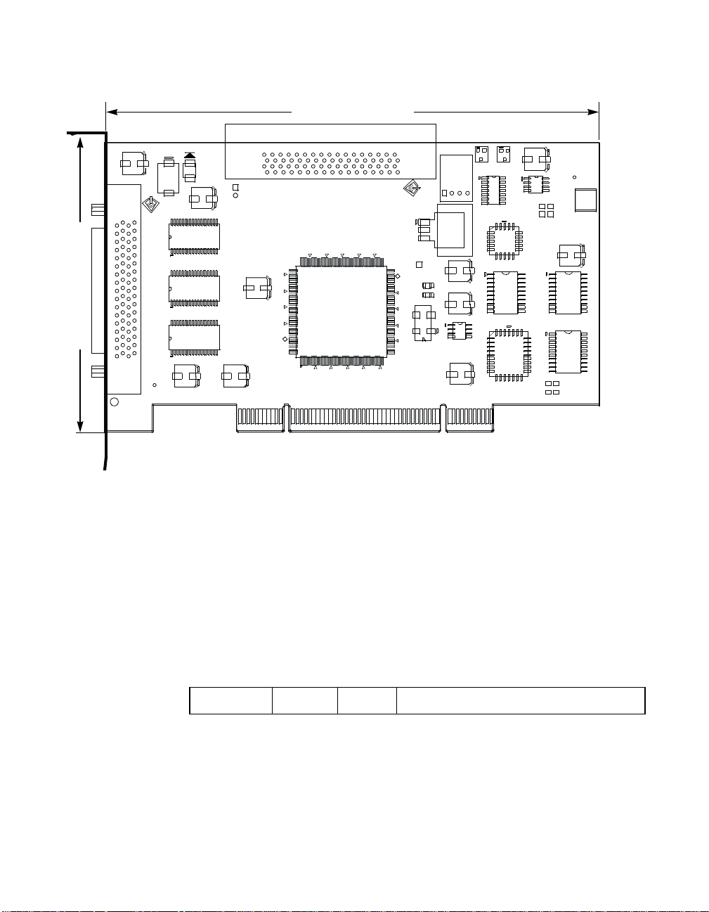
3.75 pc 10.25 pc 11.25 pc 38.25 pc
34.5 pc
Figure A.1 SYM8953U Mechanical Drawing
4.333 pc
152.4 mm (6.0 inches)
44.25 pc
F1
U4
U12 U7
CT10
CT3
CR3
J2
TERM
SYM8953U
CT6
CT9
01
88.990 mm (3.5 inches)
CT2
SCSI LVD/SE
J3
C
1998
Note:
• J1: PCI 32-bit, universal board connector.
• J2: 68-pin HD connector.
• J3: 68-pin HD connector.
• J4: 4 pin low density conne ctor.
U13
SCSI LVD/SE
J1T
+3.3 V
L1
L2
U9
VR1
Activity
J4
CT5
U8
CT7
CT8
62
U1
U3
U10
CR1
U5
CR2
5V_A
GND_A
5V_B
GND_B
U2
CT1
SIG2_A
SIG1_A
6.533’’
U11
SIG2_B
SIG1_B
ICT
CT4
U6
A.1.2 Electrical Characteristics
The SYM8953U maximum power requirement, including SCSI
TERMPWR (termination power), under normal operation is as follows:
Table A.1 Maximum Power Requirements
+5VDC ± 5% 1.5 A Over the operating range 0 °Cto55°C
Under abnormal conditions such as a short on SCSI TERMPWR, + 5 V
current may be higher. At temperatures of at least 25
4 A is sustained no longer than 30 seconds before the self-resetting
TERMPWR short circuit protection device (F1) opens.
A-2 Technical Specifications
°Cacurrentof
48.583 pc
52.5 pc
Page 65

3.75 pc 10.25 pc 11.25 pc 38.25 pc
34.5 pc
The PCI PRSNT1/ and PRSNT2/ pins are set to indicate a 7.5 W
maximum configuration.
A.1.3 Thermal, Atmospheric Characteristics
The board is designed to operate in an environment defined by the
following parameters:
• Temperature range: 0 °Cto55°C (dry bulb)
• Relative humidity range: 5% to 90% noncondensing
• Maximum dew point temperature: 32 °C
• Storage Temperature: − 45 °Cto+105°C (dry bulb)
A.1.4 Electromagnetic Compliance
The board is designed and implemented to minimize electromagnetic
emissions, susceptibility, and the effects of electromagnetic discharge.
The board meets the requirements of FCC Class B and CISPR 22 limits
and is marked with the FCC Class B Declaration of Conformity Symbol.
It also carries the CE mark.
44.25 pc
A.1.5 Safety Characteristics
4.333 pc
The bare board meets or exceeds the requirements of UL flammability
rating 94 V0. The bare board is also marked with the supplier’s name or
trademark, type, and UL flammability rating. Since this board is installed
in a PCI bus slot, all voltages are below the SELV 42.4 V limit.
A.2 Operational Environment
The SYM8953U host adapter is designed for use in PCI computer
systems. SDMS operates the board, but the design of the board does
not prevent the use of other software.
Operational Environment A-3
48.583 pc
52.5 pc
Page 66

3.75 pc 10.25 pc 11.25 pc 38.25 pc
34.5 pc
A.2.1 The PCI Interface
4.333 pc
The PCI interface operates as a 32-bit DMA bus master. The connection
is made through edge connector J1, which provides connections on both
the front and back of the board. The signal definitions and pin numbers
conform to the PCI Local Bus Specification Revision 2.2 standard.
Table A.2 and Table A.3 show the signal assignments.
44.25 pc
Note:
The + 3.3 V pins are tied together and decoupled with high
frequency bypass capacitors to ground. No current from
these 3.3 V pins is used on the board. The board derives
power from the + 5 V pins, directly and through a 3.3 V
voltage regulator. The PCI V
pins are used to
I/O
differentiate between a 5 V or a 3.3 V PCI environment.
A-4 Technical Specifications
48.583 pc
52.5 pc
Page 67

3.75 pc 10.25 pc 11.25 pc 38.25 pc
34.5 pc
4.333 pc
Table A.2 PCI Connector J1 (Front)
Signal Name Pin Signal Name Pin Signal Name Pin
−= 12 V 1 GND 22 SERR/ 42
TCK 2 AD27 23 + 3.3 V 43
GND 3 AD25 24 C_BE1/ 44
TDO 4 + 3.3 V 25 AD14 45
+ 5 V 5 C_BE3/ 26 GND 46
+ 5 V 6 AD23 27 AD12 47
INTB/ 7 GND 28 AD10 48
INTD/ 8 AD21 29 GND 49
GND (PRSNT1/) 9 AD19 30 KEYWAY 50
RESERVED 10 + 3.3 V 31 KEYWAY 51
GND (PRSNT2/) 11 AD17 32 AD08 52
44.25 pc
KEYWAY 12 C_BE2/ 33 AD07 53
KEYWAY 13 GND 34 + 3.3 V 54
RESERVED 14 IRDY/ 35 AD05 55
GND 15 + 3.3 V 36 AD03 56
CLK 16 DEVSEL/ 37 GND 57
GND 17 GND 38 AD01 58
REQ/ 18
VI/O 19 PERR/ 40
LOCK/ 39 VI/O 59
ACK64/ 60
AD31 20 + 3.3 V 41 + 5 V 61
AD29 21 + 5 V 62
1. Highlighted signals are not connected.
48.583 pc
Operational Environment A-5
52.5 pc
Page 68

3.75 pc 10.25 pc 11.25 pc 38.25 pc
34.5 pc
4.333 pc
Table A.3 PCI Connector J1 (Back)
Signal Name Pin Signal Name Pin Signal Name Pin
TRST/ 1 AD28 22 GND 42
+12V 2 AD26 23 PAR 43
TMS 3 GND 24 AD15 44
TDI 4 AD24 25 + 3.3 V 45
+ 5 V 5 IDSEL 26 AD13 46
INTA/ 6 + 3.3 V 27 AD11 47
INTC/ 7 AD22 28 GND 48
+ 5 V 8 AD20 29 AD09 49
RESERVED 9 GND 30 KEYWAY 50
+ 5 V 10 AD18 31 KEYWAY 51
RESERVED 11 AD16 32 C_BE0/ 52
44.25 pc
KEYWAY 12 + 3.3 V 33 + 3.3 V 53
KEYWAY 13 FRAME/ 34 AD06 54
RESERVED 14 GND 35 AD04 55
RST/ 15 TRDY/ 36 GND 56
VI/O 16 GND 37 AD02 57
GNT/ 17 STOP/ 38 AD00 58
GND 18 + 3.3 V 39 VI/O 59
RESERVED 19 SDONE 40 REQ64/ 60
AD30 20
SBO/ 41 + 5 V 61
+3.3V 21 +5V 62
1. Highlighted signals are not connected.
48.583 pc
A-6 Technical Specifications
52.5 pc
Page 69

3.75 pc 10.25 pc 11.25 pc 38.25 pc
34.5 pc
A.2.2 The SCSI Interface
4.333 pc
The SCSI interface conforms to ANSI X 3T10.11/1142.
The SCSI interface operates as 16-bit, synchronous or asynchronous,
SE or LVD, and supports SCSI-3 protocols and 8-bit and 16-bit
arbitration. The interface is made through connectors J2 and J3.
Active SE or LVD SCSI termination is provided automatically. SCSI
termination power is supplied by the board.
Connector J2 is a 68-pin HD right angle header used for internal
connections.
Connector J3 is a 68-pin HD right angle connector that protrudes through
the back panel bracket and is used for external connections.
Table A.4 and Table A.5 show the signal assignments for J2 and J3
respectively.
44.25 pc
48.583 pc
Operational Environment A-7
52.5 pc
Page 70

3.75 pc 10.25 pc 11.25 pc 38.25 pc
34.5 pc
Table A.4 Internal SCSI Connector J2
Signal Name Pin Signal Name Pin
SD12+ 1 SD12− 35
SD13+ 2 SD13− 36
SD14+ 3 SD14− 37
SD15+ 4 SD15− 38
SDP1+ 5 SDP1− 39
SD00+ 6 SD00− 40
SD01+ 7 SD01− 41
SD02+ 8 SD02− 42
SD03+ 9 SD03− 43
SD04+ 10 SD04− 44
SD05+ 11 SD05− 45
SD06+ 12 SD06− 46
SD07+ 13 SD07− 47
SDP0+ 14 SDP0− 48
GND 15 GND 49
DIFFSENS 16 J2_SENS 50
44.25 pc
TERMPWR 17 TERMPWR 51
TERMPWR 18 TERMPWR 52
N/C 19 N/C 53
GND 20 GND 54
SATN+ 21 SATN− 55
GND 22 GND 56
SBSY+ 23 SBSY− 57
SACK+ 24 SACK− 58
SRST+ 25 SRST− 59
SMSG+ 26 SMSG− 60
SSEL+ 27 SSEL− 61
SCD+ 28 SCD− 62
SREQ+ 29 SREQ− 63
SIO+ 30 SIO− 64
SD08+ 31 SD08− 65
SD09+ 32 SD09− 66
SD10+ 33 SD10− 67
SD11+ 34 SD11− 68
4.333 pc
A-8 Technical Specifications
48.583 pc
52.5 pc
Page 71

3.75 pc 10.25 pc 11.25 pc 38.25 pc
34.5 pc
Table A.5 External SCSI Connector J3
Signal Name Pin Signal Name Pin
SD12+ 1 SD12− 35
SD13+ 2 SD13− 36
SD14+ 3 SD14− 37
SD15+ 4 SD15− 38
SDP1+ 5 SDP1− 39
SD00+ 6 SD00− 40
SD01+ 7 SD01− 41
SD02+ 8 SD02− 42
SD03+ 9 SD03− 43
SD04+ 10 SD04− 44
SD05+ 11 SD05− 45
SD06+ 12 SD06− 46
SD07+ 13 SD07− 47
SDP0+ 14 SDP0− 48
GND 15 GND 49
DIFFSENS 16 J3_SENS 50
TERMPWR 17 TERMPWR 51
44.25 pc
TERMPWR 18 TERMPWR 52
N/C 19 N/C 53
GND 20 GND 54
SATN+ 21 SATN− 55
GND 22 GND 56
SBSY+ 23 SBSY− 57
SACK+ 24 SACK− 58
SRST+ 25 SRST− 59
SMSG+ 26 SMSG− 60
SSEL+ 27 SSEL− 61
SCD+ 28 SCD− 62
SREQ+ 29 SREQ− 63
SIO+ 30 SIO− 64
SD08+ 31 SD08− 65
SD09+ 32 SD09− 66
SD10+ 33 SD10− 67
SD11+ 34 SD11− 68
4.333 pc
Note: When operated in the SE mode, all signals with the + suffix are clamped
to ground.
Operational Environment A-9
48.583 pc
52.5 pc
Page 72

3.75 pc 10.25 pc 11.25 pc 38.25 pc
34.5 pc
A.2.3 On-Board LED
4.333 pc
On-board LEDs are used to indicate the status of the SCSI bus.
The SCSI Activity LED lights when the SCSI bus is transferring
information.
A.2.4 The SCSI Busy LED
The SCSI Activity LED interface on the SYM8953U is a four-wire
arrangement that allows the user to connect a LED harness to the board.
The buffered GPIO0_FETCH line (maximum output low voltage 0.4 V
and minimum output low current 16 mA) is pulled low to complete the
circuit when a harness with a LED is attached. The SCSI Busy LED
connector is J4.
Table A.6 LED Connector J4
Signal Name Pin
44.25 pc
LED+ 1
LED− 2
LED− 3
LED+ 4
48.583 pc
A-10 Technical Specifications
52.5 pc
Page 73

3.75 pc 10.25 pc 11.25 pc 38.25 pc
34.5 pc
4.333 pc
Appendix B
Glossary of Terms and
Abbreviations
12 pc
12.938 pc
Active
Termination
Address A specific location in memory, designated either numerically or by a
The electrical connection required at each end of the SCSI bus,
composed of active voltage regulation and a set of termination resistors.
Ultra and Ultra2 SCSI require active termination.
symbolic name.
13.851 pc
34.732 pc
Asynchronous
Data Transfer
BIOS Basic Input/Output System. Software that provides basic read/write
Bit A binary digit. The smallest unit of information a computer uses. The
Bus A collection of unbroken signal lines across which information is
Bus Mastering A high-performance way to transfer data. The host adapter controls the
Byte A unit of information consisting of eight bits.
CISPR A special international committee on radio interference (Committee,
One of the ways data is transferred over the SCSI bus. It is slower than
synchronous data transfer.
capability. Usually kept as firmware (ROM based). The system BIOS on
the mainboard of a computer is used to boot and control the system. The
SCSI BIOS on your host adapter acts as an extension of the system
BIOS.
value of a bit (0 or 1) represents a two-way choice, such as on or off,
true or false, and so on.
transmitted from one part of a computer system to another. Connections
to the bus are made using taps on the lines.
transfer of data directly to and from system memory without interrupting
the computer’s microprocessor. This is the fastest way for multitasking
operating systems to transfer data.
International and Special, for Protection in Radio).
Symbios SYM8953U PCI to Ultra2 SCSI Host Adapter B-1
48.583 pc
52.5 pc
Page 74

3.75 pc 10.25 pc 11.25 pc 38.25 pc
34.5 pc
Configuration Refers to the way a computer is set up; the combined hardware
4.333 pc
components (computer, monitor, keyboard, and peripheral devices) that
make up a computer system; or the software settings that allow the
hardware components to communicate with each other.
CPU Central Processing Unit. The “brain” of the computer that performs the
actual computations. The term Microprocessor Unit (MPU) is also used.
44.25 pc
DMA Bus
Master
A feature that allows a peripheral to control the flow of data to and from
system memory by blocks, as opposed to PIO (Programmed I/O) where
the processor is in control and the flow is by byte.
Device Driver A program that allows a microprocessor (through the operating system)
to direct the operation of a peripheral device.
Differential SCSI A hardware configuration for connecting SCSI devices. It uses a pair of
lines for each signal transfer (as opposed to Single-Ended SCSI which
references each SCSI signal to a common ground).
Dword A double word is a group of four consecutive bytes or characters that are
stored, addressed, transmitted, and operated on as a unit. The lower two
address bits of the least significant byte must equal zero in order to be
dword aligned.
EEPROM Electronically Erasable Programmable Read Only Memory. A memory
chip typically used to store configuration information. See NVRAM.
EISA Extended Industry Standard Architecture. An extension of the 16-bit ISA
bus standard. It allows devices to perform 32-bit data transfers.
External SCSI
Device
A SCSI device installed outside the computer cabinet. These devices are
connected in a continuous chain using specific types of shielded cables.
Fast-20 The SCSI Trade Association (STA) supports the use of “Ultra SCSI” over
the term “Fast-20”. Please See Ultra SCSI.
Fast-40 The SCSI Trade Association (ST A) supports the use of “Ultra2 SCSI”
over the term “Fast-40”. Please see Ultra2 SCSI.
Fast SCSI A standard for SCSI data transfers. It allows a transfer rate of up to 10
Mbytes/s over an 8-bit SCSI bus and up to 20 Mbytes/s over a 16-bit
SCSI bus.
FCC Federal Communications Commission.
B-2 Glossary of Terms and Abbreviations
48.583 pc
52.5 pc
Page 75

3.75 pc 10.25 pc 11.25 pc 38.25 pc
34.5 pc
File A named collection of information stored on a disk.
4.333 pc
Firmware Software that is permanently stored in ROM. Therefore, it can be
accessed during boot time.
Hard Disk A disk made of metal and permanently sealed into a drive cartridge. A
hard disk can store very large amounts of information.
Host The computer system in which a SCSI host adapter is installed. It uses
the SCSI host adapter to transfer information to and from devices
attached to the SCSI bus.
Host Adapter A circuit board or integrated circuit that provides a SCSI bus connection
to the computer system.
44.25 pc
Internal SCSI
Device
A SCSI device installed inside the computer cabinet. These devices are
connected in a continuous chain using an unshielded ribbon cable.
IRQ Interrupt Request Channel. A path through which a device can get the
immediate attention of the computer’s CPU. The PCI bus assigns an IRQ
path for each SCSI host adapter.
ISA Industry Standard Architecture. A type of computer bus used in most
PCs.Itallowsdevicestosendandreceivedataupto16bitsatatime.
Kbyte Kilobyte. A measure of computer storage equal to 1024 bytes.
Local Bus A way to connect peripherals directly to computer memory. It bypasses
the slower ISA and EISA buses. PCI is a local bus standard.
Logical Unit A subdivision, either logical or physical, of a SCSI device (actually the
place for the device on the SCSI bus). Most devices have only one logical
unit, but up to eight are allowed for each of the eight possible devices on
aSCSIbus.
LUN Logical Unit Number. An identifier, zero to seven, for a logical unit.
LVD Link Low Voltage Differential link allows greater Ultra2 SCSI device
connectability and longer SCSI cables. LVD Link lowers the amplitude of
noise reflections and allows higher transmission frequencies. Detailed
information may be found in Section 1.3.4, “LVD Link Technology”.
Mainboard A large circuit board that holds RAM, ROM, the microprocessor, custom
integrated circuits, and other components that make a computer work. It
also has expansion slots for host adapters and other expansion boards.
B-3
48.583 pc
52.5 pc
Page 76

3.75 pc 10.25 pc 11.25 pc 38.25 pc
34.5 pc
Main Memory The part of a computer’s memory which is directly accessible by the CPU
4.333 pc
(usually synonymous with RAM).
Mbyte Megabyte. A measure of computer storage equal to 1024 kilobytes.
Motherboard See Mainboard. In some countries, the term Motherboard is not
appropriate.
Multitasking The executing of more than one command at the same time. This allows
programs to operate in parallel.
Multithreading The simultaneous accessing of data by more than one SCSI device. This
increases the data throughput.
NVRAM NonVolatile Random Access Memory. Actually an EEPROM
(Electronically Erasable Read Only Memory chip) used to store
configuration information. See EEPROM.
44.25 pc
Operating
System
A program that organizes the internal activities of the computer and its
peripheral devices. An operating system performs basic tasks such as
moving data to and from devices, and managing inf ormation in memory.
It also provides the user interface.
Parity Checking A way to verify the accuracy of data transmitted over the SCSI bus. The
parity bit in the transfer is used to make the sum of all the 1 bits either
odd or even (for odd or even parity). If the sum is not correct, the
information may be retransmitted or an error message may appear.
Passive
Termination
The electrical connection required at each end of the SCSI bus,
composed of a set of resistors. It improves the integrity of bus signals.
PCI Peripheral Component Interconnect. A local bus specification that allows
connection of peripherals directly to computer memory. It bypasses the
slower ISA and EISA buses.
Peripheral
Devices
A piece of hardware (such as a video monitor, disk drive, printer, or
CD-ROM) used with a computer and under the computer’s control. SCSI
peripherals are controlled through a SCSI host adapter.
Pin-1
Orientation
The alignment of pin 1 on a SCSI cable connector and the pin-1 position
on the SCSI connector into which it is inserted. External SCSI cables are
always keyed to insure proper alignment, but internal SCSI ribbon cables
sometimes are not keyed.
B-4 Glossary of Terms and Abbreviations
48.583 pc
52.5 pc
Page 77

3.75 pc 10.25 pc 11.25 pc 38.25 pc
34.5 pc
PIO Programmed Input/Output. A way the CPU can transfer data to and from
memory using the computer’s I/O ports. PIO is usually faster than DMA,
but requires CPU time.
Port Address Also Port Number. The address through which commands are sent to a
host adapter board. This address is assigned by the PCI bus.
Port Number See Port Address.
Queue Tags A way to keep track of multiple commands that allow for increased
throughput on the SCSI bus.
RAM Random Access Memory. The computer’s primary working memory in
which program instructions and data are stored and are accessible to the
CPU. Information can be written to and read from RAM. The contents of
RAM are lost when the computer is turned off.
RISC Core LSI Logic SCSI chips contain a RISC (Reduced Instruction Set
Computer) processor, programmed through microcode scripts.
ROM Read Only Memory. Memory from which information can be read but not
changed. The contents of ROM are not erased when the computer is
44.25 pc
turned off.
4.333 pc
SCAM SCSI Configured AutoMatically. A method to automatically allocate SCSI
IDs using software when SCAM compliant SCSI devices are attached.
SCSI Small Computer System Interface. A specification for a high-performance
peripheral bus and command set. The original standard is referred to as
SCSI-1.
SCSI-2 The current SCSI specification which adds features to the original
SCSI-1 standard.
SCSI-3 The SCSI specification which adds features to the SCSI-2 standard.
SCSI Bus A host adapter and one or more SCSI peripherals connected by cables
in a linear chain configuration. The host adapter may exist anywhere on
the chain, allowing connection of both internal and external SCSI
devices. A system may have more than one SCSI bus by using multiple
host adapters.
B-5
48.583 pc
52.5 pc
Page 78

3.75 pc 10.25 pc 11.25 pc 38.25 pc
34.5 pc
SCSI Device Any device that conforms to the SCSI standard and is attached to the
4.333 pc
SCSI bus by a SCSI cable. This includes SCSI host adapters and SCSI
peripherals.
SCSI ID A way to uniquely identify each SCSI device on the SCSI bus. Each SCSI
bus has eight available SCSI IDs numbered 0 through 7 (or 0 through 15
for Wide SCSI). The host adapter usually gets the highest ID (7 or 15)
giving it priority to control the bus.
SCSI SCRIPTS A SCSI programming language that works with the SCRIPTS processor
that is embedded on the SYM53C8XX device. These SCRIPTS reside in
in host computer system memory.
44.25 pc
SCRIPTS
Processor
The SCRIPTS processor allows users to fine tune SCSI operations with
regard to unique vendor commands or new SCSI specifications. The
SCRIPTS processor fetches SCRIPTS instructions from system memory
to control operation of the SYM53C8XX device.
SDMS SCSI Device Management System. A LSI Logic software product that
manages SCSI system I/O.
Single-Ended
SCSI
A hardware specification for connecting SCSI devices. It references each
SCSI signal to a common ground. This is the most common method (as
opposed to differential SCSI which uses a separate ground for each
signal).
STA SCSI Tr ade Association. A group of companies that cooperate to
promote SCSI parallel interface technology as a viable mainstream I/O
interconnect for commercial computing.
Synchronous
Data Transfer
One of the ways data is transferred over the SCSI bus. T ransfers are
clocked with fixed frequency pulses. This is faster than asynchronous
data transfer . Synchronous data transfers are negotiated between the
SCSI host adapter and each SCSI device.
System BIOS Controls the low-level POST (Power On Self Test), and basic operation
of the CPU and computer system.
Ultra SCSI A standard for SCSI data transfers. It allows a transfer rate of up to
20 Mbytes/s over an 8-bit SCSI bus and up to 40 Mbytes/s over a 16-bit
SCSI bus. SCSI T rade Association (STA) supports using the term “Ultra
SCSI”overtheolderterm“Fast-20”.
B-6 Glossary of Terms and Abbreviations
48.583 pc
52.5 pc
Page 79

3.75 pc 10.25 pc 11.25 pc 38.25 pc
34.5 pc
Ultra2 SCSI A standard for SCSI data transfers. It allows a transfer rate of up to
4.333 pc
40 Mbytes/s over an 8-bit SCSI bus, and up to 80 Mbytes/s over a
16-bit SCSI bus. SCSI Trade Association (STA) supports using the term
“Ultra2 SCSI” over the term “Fast-40”.
VCCI Voluntary Control Council for Interference.
VDE Verband Deucher Elektroniker (Association of German Electrical
Engineers).
Virtual Memory Space on a hard disk that can be used as if it were RAM.
Wide SCSI A SCSI-2 feature allowing 16-bit or 32-bit transfers on the SCSI bus. This
dramatically increases the transfer rate over the standard 8-bit SCSI bus.
Wide Ultra SCSI The SCSI Trade Association (ST A) term for SCSI bus width 16-bits, SCSI
bus speed maximum data rate 40 Mbytes/s.
44.25 pc
Wide Ultra2
SCSI
The SCSI Trade Association (STA) term for SCSI bus width 16-bits, SCSI
bus speed maximum data rate 80 Mbytes/s.
Word A two byte (or 16-bit) unit of information.
B-7
48.583 pc
52.5 pc
Page 80

3.75 pc 10.25 pc 11.25 pc 38.25 pc
34.5 pc
4.333 pc
44.25 pc
48.583 pc
B-8 Glossary of Terms and Abbreviations
52.5 pc
Page 81

3.75 pc 10.25 pc 11.25 pc 38.25 pc
34.5 pc
Index
duplication of SCSI IDs 2-22
E
edge connector 2-5
Electrical Characteristics A-2
Electromagnetic Compliance A-3
Erroneous Termination 2-18
External SCSI B us Connections 2-15
External SCSI Connector J3 A-9
External SCSI Device 2-16
External SCSI Device Termination 2-20
F
FDISK/MBR command
using 3-9
Features 1-2
format
description 3-14
front panel LED 2-14
G
global properties menu 3-18, 3-20
GPIO0_FETCH line A-10
H
Hardware Connections 2-5
host S CSI ID
description 3-8
I
Inserting the Host Adapter 2-4, 2-6
Installation Procedure 2-3
installation procedure check list 2-24
Internal SCSI Bus Connections 2-10
Internal SCSI Device Connection 2-11
Internal SCSI Dev ice Termination 2-19
Internal SCSI Ribbon Cable 2-10
34.732 pc
A
adapter
description 3-5
adapter properties menu 3-6
alternate CHS mapping
description 3-9
B
Board Characteristics 1-3
boot adapter list menu 3-16
boot choice
description 3-14
boot information display mode
description 3-19
boot order
description 3-6
Bus configurations 2-18
C
chained connection 2-12, 2-17
CHS mapping
description 3-9
Configuration Utility 3-1
Connecting the SCSI Peripherals 2-7
current s tatus
description 3-17
D
data width
description 3-13
Detailed Installation Procedure 2-3
device identifier
description 3-13
device pr operties menu 3-11 to 3-12
Device Selections Menu 3-10
device/function
description 3-6
disconnect
description 3-14
4.333 pc
12 pc
12.938 pc
13.851 pc
48.583 pc
Symbios SYM8953U PCI to Ultra2 SCSI Host Adapter IX-1
52.5 pc
Page 82

3.75 pc 10.25 pc 11.25 pc 38.25 pc
34.5 pc
44.25 pc
IRQ
interrupt request line 3-6
L
LED c able 2-14
LED Connector 2-14
LVD Link Technology 1-5
M
Main Menu Display 3-4
menus
device pr operties 3-11 to 3-12
global properties 3-18
Multiple Internal SCSI Devices 2-13
N
next boot
description 3-17
NVM
nonvolatile memory 3-6
O
Operational Environment A-3
P
PCI bus
description 3-5
PCI Connector J1 (Back) A-6
PCI Connector J1 (Front) A-5
PCI Interf a ce 1-2, 1-4, A-4
peripheral device SCSI IDs 2-22
peripheral device terminators 2-18
Physical Characteristics A-1
Physical Environment A-1
port number
description 3-6
Q
queue tags
description 3-14
R
removable media support
description 3-8
ribbon cable 2-7
S
Safety Characteristics A-3
scan ID
description 3-13
scan LUNs
description 3-13
SCSI BIOS Configuration Utility 3-1
SCSI bus connections 2-7
SCSI bus s can orde r
description 3-8
SCSI bus termination 2-18
SCSI Busy LED A-10
SCSI Device Management System (SDMS) 1-1
SCSI ID
description 3-13
SCSI IDs 2-22
SCSI Interface 1-2, 1-4, A-7
SCSI LED Connector 2-14
SCSI parity
description 3-8
SCSI Peripherals 2-7
SCSI Ribbon Cable 2-10
SCSI time-out
description 3-14
secondary cluster server
description 3-9
Setting SCSI IDs 2-22
spinup delay
description 3-9
Starting the SCSI BIOS Configuration Utility 3-1
sync rate
description 3-13
T
Termination 2-18
Termination (erroneous) 2-18
termination control
description 3-9
Thermal, Atmospheric Characteristics A-3
U
Ultra SCSI 2-7
Ultra2 SCSI 1-5
V
verify
description 3-14
video mode
description 3-19
4.333 pc
IX-2 Index
48.583 pc
52.5 pc
Page 83

Customer Feedback
We would appreciate your feedback on this document. Please copy the
following page, add your comments, and fax it to us at the number
shown.
If appropriate, please also fax copies of any marked-up pages from this
document.
Important:
Thank you for your help in improving the quality of our documents.
Please include your name, phone number, fax number, and
company address so that we may contact you directly for
clarification or additional information.
Page 84

Reader’s Comments
Fax your comments to: LSI Logic Corporation
Technical Publications
M/S E-198
Fax: 408.433.4333
Please tell us how you rate this document: Symbios® SYM8953U PCI to
Ultra2 SCSI User’s Guide. Place a check mark in the appropriate blank
for each category.
Excellent Good Average Fair Poor
Completeness of information ____ ____ ____ ____ ____
Clarity of information ____ ____ ____ ____ ____
Ease of finding information ____ ____ ____ ____ ____
Technical content ____ ____ ____ ____ ____
Usefulness of examples and
illustrations
Overall manual ____ ____ ____ ____ ____
____ ____ ____ ____ ____
Whatcouldwedotoimprovethisdocument?
If you found errors in this document, please specify the error and page
number. If appropriate, please fax a marked-up copy of the page(s).
Please complete the information below so that we may contact you
directly for clarification or additional information.
Name Date
Telephone
Fax
Title
Department Mail Stop
Company Name
Street
City, State, Zip
Customer Feedback
Page 85

U.S. Distributors
by State
A. E. Avnet Electronics
http://www.hh.avnet.com
B. M. Bell Microproducts,
Inc. (for HAB’s)
http://www.bellmicro.com
I. E. Insight Electronics
http://www.insight-electronics.com
W.E. Wyle Electronics
http://www.wyle.com
Alabama
Daphne
I. E. Tel: 334.626.6190
Huntsville
A. E. Tel: 256.837.8700
I. E. Tel: 256.830.1222
W.E. Tel: 800.964.9953
Alaska
A. E. Tel: 800.332.8638
Arkansas
W.E. Tel: 972.235.9953
Arizona
Phoenix
A. E. Tel: 480.736.7000
B. M. Tel: 602.267.9551
W.E. Tel: 800.528.4040
Tempe
I. E. Tel: 480.829.1800
Tucson
A. E. Tel: 520.742.0515
California
Agoura Hills
B. M. Tel: 818.865.0266
Irvine
A. E. Tel: 949.789.4100
B. M. Tel: 949.470.2900
I. E. Tel: 949.727.3291
W.E. Tel: 800.626.9953
Los Angeles
A. E. Tel: 818.594.0404
W.E. Tel: 800.288.9953
Sacramento
A. E. Tel: 916.632.4500
W.E. Tel: 800.627.9953
San Diego
A. E. Tel: 858.385.7500
B. M. Tel: 858.597.3010
I. E. Tel: 800.677.6011
W.E. Tel: 800.829.9953
San Jose
A. E. Tel: 408.435.3500
B. M. Tel: 408.436.0881
I. E. Tel: 408.952.7000
Santa Clara
W.E. Tel: 800.866.9953
Woodland Hills
A. E. Tel: 818.594.0404
Westlake Village
I. E. Tel: 818.707.2101
Colorado
Denver
A. E. Tel: 303.790.1662
B. M. Tel: 303.846.3065
W. E. Tel: 800.933.9953
Englewood
I. E. Tel: 303.649.1800
Connecticut
Cheshire
A. E. Tel: 203.271.5700
I. E. Tel: 203.272.5843
Wallingford
W. E. Tel: 800.605.9953
Delaware
North/South
A. E. Tel: 800.526.4812
Tel: 800.638.5988
B. M. Tel: 302.328.8968
W. E. Tel: 856.439.9110
Florida
Altamonte Springs
B. M. Tel: 407.682.1199
I. E. Tel: 407.834.6310
Boca Raton
I. E. Tel: 561.997.2540
Clearwater
I. E. Tel: 727.524.8850
Fort Lauderdale
A. E. Tel: 954.484.5482
W. E. Tel: 800.568.9953
Miami
B. M. Tel: 305.477.6406
Orlando
A. E. Tel: 407.657.3300
W. E. Tel: 407.740.7450
Tampa
W. E. Tel: 800.395.9953
St. Petersburg
A. E. Tel: 727.507.5000
Georgia
Atlanta
A. E. Tel: 770.623.4400
B. M. Tel: 770.980.4922
W. E. Tel: 800.876.9953
Duluth
I. E. Tel: 678.584.0812
Hawaii
A. E. Tel: 800.851.2282
Idaho
A. E. Tel: 801.365.3800
W. E. Tel: 801.974.9953
Illinois
North/South
A. E. Tel: 847.797.7300
Tel: 314.291.5350
Chicago
B. M. Tel: 847.413.8530
W. E. Tel: 800.853.9953
Schaumburg
I. E. Tel: 847.885.9700
Indiana
Fort Wayne
I. E. Tel: 219.436.4250
W. E. Tel: 888.358.9953
Indianapolis
A. E. Tel: 317.575.3500
Iowa
W. E. Tel: 612.853.2280
Cedar Rapids
A. E. Tel: 319.393.0033
Kansas
W. E. Tel: 303.457.9953
Kansas City
A. E. Tel: 913.663.7900
Lenexa
I. E. Tel: 913.492.0408
Kentucky
W. E. Tel: 937.436.9953
Central/Northern/ Western
A. E. Tel: 800.984.9503
Tel: 800.767.0329
Tel: 800.829.0146
Louisiana
W. E. Tel: 713.854.9953
North/South
A. E. Tel: 800.231.0253
Tel: 800.231.5575
Maine
A. E. Tel: 800.272.9255
W. E. Tel: 781.271.9953
Maryland
Baltimore
A. E. Tel: 410.720.3400
W. E. Tel: 800.863.9953
Columbia
B. M. Tel: 800.673.7461
I. E. Tel: 410.381.3131
Massachusetts
Boston
A. E. Tel: 978.532.9808
W. E. Tel: 800.444.9953
Burlingtonr
I. E. Tel: 781.270.9400
Marlborough
B. M. Tel: 508.480.9099
Woburn
B. M. Tel: 781.933.9010
Michigan
Brighton
I. E. Tel: 810.229.7710
Detroit
A. E. Tel: 734.416.5800
W. E. Tel: 888.318.9953
Minnesota
Champlin
B. M. Tel: 800.557.2566
Eden Prairie
B. M. Tel: 800.255.1469
Minneapolis
A. E. Tel: 612.346.3000
W. E. Tel: 800.860.9953
St. Louis Park
I. E. Tel: 612.525.9999
Mississippi
A. E. Tel: 800.633.2918
W. E. Tel: 256.830.1119
Missouri
W. E. Tel: 630.620.0969
St. Louis
A. E. Tel: 314.291.5350
I. E. Tel: 314.872.2182
Montana
A. E. Tel: 800.526.1741
W. E. Tel: 801.974.9953
Nebraska
A. E. Tel: 800.332.4375
W. E. Tel: 303.457.9953
Nevada
Las Vegas
A. E. Tel: 800.528.8471
W. E. Tel: 702.765.7117
New Hampshire
A. E. Tel: 800.272.9255
W. E. Tel: 781.271.9953
New Jersey
North/South
A. E. Tel: 201.515.1641
Tel: 609.222.6400
Mt. L aurel
I. E. Tel: 609.222.9566
Pine Brook
W. E. Tel: 800.862.9953
Parsippany
I. E. Tel: 973.299.4425
Wayne
W. E. Tel: 973.237.9010
New Mexico
W. E. Tel: 480.804.7000
Albuquerque
A. E. Tel: 505.293.5119
Page 86

U.S. Distributors
by State
(Continued)
New York
Hauppauge
I. E. Tel: 516.761.0960
Long Island
A. E. Tel: 516.434.7400
W.E. Tel: 800.861.9953
Rochester
A. E. Tel: 716.475.9130
I. E. Tel: 716.242.7790
W.E. Tel: 800.319.9953
Smithtown
B. M. Tel: 800.543.2008
Syracuse
A. E. Tel: 315.449.4927
North Carolina
Raleigh
A. E. Tel: 919.859.9159
I. E. Tel: 919.873.9922
W.E. Tel: 800.560.9953
North Dakota
A. E. Tel: 800.829.0116
W.E. Tel: 612.853.2280
Ohio
Cleveland
A. E. Tel: 216.498.1100
W.E. Tel: 800.763.9953
Dayton
A. E. Tel: 614.888.3313
I. E. Tel: 937.253.7501
W.E. Tel: 800.575.9953
Strongsville
B. M. Tel: 440.238.0404
Valley View
I. E. Tel: 216.520.4333
Oklahoma
W.E. Tel: 972.235.9953
Tulsa
A. E. Tel: 918.459.6000
I. E. Tel: 918.665.4664
Oregon
Beavertonr
B. M. Tel: 503.524.0787
I. E. Tel: 503.644.3300
Portland
A. E. Tel: 503.526.6200
W.E. Tel: 800.879.9953
Pennsylvania
Mercer
I. E. Tel: 412.662.2707
Pittsburgh
A. E. Tel: 412.281.4150
W.E. Tel: 440.248.9996
Philadelphia
A. E. Tel: 800.526.4812
B. M. Tel: 215.741.4080
W.E. Tel: 800.871.9953
Rhode Island
A. E. 800.272.9255
W.E. Tel: 781.271.9953
South Carolina
A. E. Tel: 919.872.0712
W. E. Tel: 919.469.1502
South D akota
A. E. Tel: 800.829.0116
W. E. Tel: 612.853.2280
Tennessee
W. E. Tel: 256.830.1119
East/West
A. E. Tel: 800.241.8182
Tel: 800.633.2918
Texas
Austin
A. E. Tel: 512.219.3700
B. M. Tel: 512.258.0725
I. E. Tel: 512.719.3090
W. E. Tel: 800.365.9953
Dallas
A. E. Tel: 214.553.4300
B. M. Tel: 972.783.4191
W. E. Tel: 800.955.9953
El Paso
A. E. Tel: 800.526.9238
Houston
A. E. Tel: 713.781.6100
B. M. Tel: 713.917.0663
W. E. Tel: 800.888.9953
Richardson
I. E. Tel: 972.783.0800
Rio Grande Valley
A. E. Tel: 210.412.2047
Stafford
I. E. Tel: 281.277.8200
Utah
Centerville
B. M. Tel: 801.295.3900
Murray
I. E. Tel: 801.288.9001
Salt LakeCity
A. E. Tel: 801.365.3800
W. E. Tel: 800.477.9953
Vermont
A. E. Tel: 800.272.9255
W. E. Tel: 716.334.5970
Virginia
A. E. Tel: 800.638.5988
W. E. Tel: 301.604.8488
Washington
Kirkland
I. E. Tel: 425.820.8100
Seattle
A. E. Tel: 425.882.7000
W. E. Tel: 800.248.9953
West Virginia
A. E. Tel: 800.638.5988
Wisconsin
Milwaukee
A. E. Tel: 414.513.1500
W. E. Tel: 800.867.9953
Wauwatosa
I. E. Tel: 414.258.5338
Wyoming
A. E. Tel: 800.332.9326
W. E. Tel: 801.974.9953
Page 87

Direct Sales
Representatives by State
(Component and HAB)
E. A. Earle Associates
E. L. Electrodyne - UT
GRP Group 2000
I. S. Infinity Sales, Inc.
ION ION Associates, Inc.
R. A. Rathsburg Associ-
ates, Inc.
SGY Synergy Associates,
Inc.
Arizona
Tempe
E. A. Tel: 480.921.3305
California
Calabasas
I. S. Tel: 818.880.6480
Irvine
I. S. Tel: 714.833.0300
San Diego
E. A. Tel: 619.278.5441
Illinois
Elmhurst
R. A. Tel: 630.516.8400
Indiana
Cicero
R. A. Tel: 317.984.8608
Ligonier
R. A. Tel: 219.894.3184
Plainfield
R. A. Tel: 317.838.0360
Massachusetts
Burlington
SGY Tel:781.238.0870
Michigan
Byron Center
R. A. Tel: 616.554.1460
Good Rich
R. A. Tel: 810.636.6060
Novi
R. A. Tel: 810.615.4000
North Carolina
Cary
GRP Tel: 919.481.1530
Ohio
Columbus
R. A. Tel: 614.457.2242
Dayton
R. A. Tel: 513.291.4001
Independence
R. A. Tel: 216.447.8825
Pennsylvania
Somerset
R. A. Tel: 814.445.6976
Texas
Austin
ION Tel: 512.794.9006
Arlington
ION Tel: 817.695.8000
Houston
ION Tel: 281.376.2000
Utah
Salt LakeCity
E. L. Tel: 801.264.8050
Wisconsin
Muskego
R. A. Tel: 414.679.8250
Saukville
R. A. Tel: 414.268.1152
Page 88

Sales Offices and Design
Resource Centers
LSI Logic Corporation
CorporateHeadquarters
Tel: 408.433.8000
Fax: 408.433.8989
NORTH AMERICA
California
Costa Mesa -Mint Technology
Tel: 949.752.6468
Fax: 949.752.6868
Irvine
♦Tel: 949.809.4600
Fax: 949.809.4444
Pleasanton Design Center
Tel: 925.730.8800
Fax: 925.730.8700
San Diego
Tel: 858.467.6981
Fax: 858.496.0548
Silicon Valley
♦Tel: 408.433.8000
Fax: 408.954.3353
Wireless Design Center
Tel: 858.350.5560
Fax: 858.350.0171
Colorado
Boulder
♦Tel: 303.447.3800
Fax: 303.541.0641
Colorado Springs
Tel: 719.533.7000
Fax: 719.533.7020
Fort Collins
Tel: 970.223.5100
Fax: 970.206.5549
Florida
Boca Raton
Tel: 561.989.3236
Fax: 561.989.3237
Georgia
Alpharetta
Tel: 770.753.6146
Fax: 770.753.6147
Illinois
Oakbrook Terrace
Tel: 630.954.2234
Fax: 630.954.2235
Kentucky
Bowling Green
Tel: 270.793.0010
Fax: 270.793.0040
Maryland
Bethesda
Tel: 301.897.5800
Fax:301.897.8389
Massachusetts
Waltham
♦Tel: 781.890.0180
Fax:781.890.6158
Burlington - Mint Technology
Tel: 781.685.3800
Fax:781.685.3801
Minnesota
Minneapolis
♦Tel: 612.921.8300
Fax:612.921.8399
New Jersey
Red Bank
Tel: 732.933.2656
Fax:732.933.2643
Cherry Hill - Mint Technology
Tel: 609.489.5530
Fax:609.489.5531
New York
Fairport
Tel: 716.218.0020
Fax:716.218.9010
North Carolina
Raleigh
Tel: 919.785.4520
Fax:919.783.8909
Oregon
Beaverton
Tel: 503.645.0589
Fax:503.645.6612
Texas
Austin
Tel: 512.388.7294
Fax:512.388.4171
Plano
♦Tel: 972.244.5000
Fax:972.244.5001
Houston
Tel: 281.379.7800
Fax:281.379.7818
Canada
Ontario
Ottawa
♦Tel: 613.592.1263
Fax:613.592.3253
INTERNATIONAL
France
Paris
LSI Logic S.A.
Immeuble Europa
♦Tel: 33.1.34.63.13.13
Fax: 33.1.34.63.13.19
Germany
Munich
LSI Logic GmbH
♦Tel: 49.89.4.58.33.0
Fax:49.89.4.58.33.108
Stuttgart
Tel: 49.711.13.96.90
Fax: 49.711.86.61.428
Italy
Milano
LSI Logic S.P.A.
♦Tel: 39.039.687371
Fax: 39.039.6057867
Japan
Tokyo
LSI Logic K.K.
♦Tel:81.3.5463.7821
Fax: 81.3.5463.7820
Osaka
♦Tel: 81.6.947.5281
Fax: 81.6.947.5287
Korea
Seoul
LSI Logic Corporation of
Korea Ltd
Tel: 82.2.528.3400
Fax: 82.2.528.2250
The Netherlands
Eindhoven
LSI Logic Europe Ltd
Tel: 31.40.265.3580
Fax: 31.40.296.2109
Singapore
Singapore
LSI Logic Pte Ltd
Tel: 65.334.9061
Fax: 65.334.4749
Tel: 65.835.5040
Fax: 65.732.5047
Sweden
Stockholm
LSI Logic AB
♦Tel: 46.8.444.15.00
Fax: 46.8.750.66.47
Taiwan
Taipe i
LSILogicAsia,Inc.
Taiwan Branch
Tel: 886.2.2718.7828
Fax:886.2.2718.8869
United Kingdom
Bracknell
LSI Logic Europe Ltd
♦Tel: 44.1344.426544
Fax: 44.1344.481039
♦Sales Officeswith
Design Resource Centers
Page 89

International Distributors
Australia
New South Wales
ReptechnicPty Ltd
♦Tel: 612.9953.9844
Fax: 612.9953.9683
Belgium
Acal nv/sa
Tel: 32.2.7205983
Fax: 32.2.7251014
China
Beijing
LSI Logic International
Services Inc.
Tel: 86.10.6804.2534
Fax: 86.10.6804.2521
France
Rungis Cedex
Azzurri Technology France
Tel: 33.1.41806310
Fax: 33.1.41730340
Germany
Haar
EBV Elektronik
Tel: 49.89.4600980
Fax: 49.89.46009840
Munich
Avnet Emg GmbH
Tel: 49.89.45110102
Fax:49.89.42.27.75
Wuennenberg-Haaren
Peacock AG
Tel: 49.2957.79.1692
Fax: 49.2957.79.9341
Hong Kong
Hong Kong
AVT Industrial Ltd
Tel: 852.2428.0008
Fax: 852.2401.2105
EastEle
Tel: 852.2798.8860
Fax: 852.2305.0640
India
Bangalore
Spike Technologies India
Private Ltd
♦Tel: 91.80.664.5530
Fax: 91.80.664.9748
Israel
Tel Aviv
Eastronics Ltd
Tel: 972.3.6458777
Fax: 972.3.6458666
Japan
Tokyo
Global Electronics
Corporation
Tel: 81.3.3260.1411
Fax: 81.3.3260.7100
Technical Center
Tel: 81.471.43.8200
Yokohama-City
Macnica Corporation
Tel: 81.45.939.6140
Fax: 81.45.939.6141
The Netherlands
Eindhoven
Acal Nederland b.v.
Tel: 31.40.2.502602
Fax: 31.40.2.510255
Switzerland
Brugg
LSI Logic Sulzer AG
Tel: 41.32.3743232
Fax: 41.32.3743233
Taiwan
Taipei
Avnet-Mercuries
Corporation,Ltd
Tel: 886.2.2516.7303
Fax:886.2.2505.7391
Lumax International
Corporation,Ltd
Tel: 886.2.2788.3656
Fax:886.2.2788.3568
Prospect Technology
Corporation,Ltd
Tel: 886.2.2721.9533
Fax:886.2.2773.3756
Serial Semiconductor
Corporation,Ltd
Tel: 886.2.2579.5858
Fax:886.2.2570.3123
United Kingdom
Maidenhead
Azzurri Technology Ltd
Tel: 44.1628.826826
Fax:44.1628.829730
Swindon
EBV Elektronik
Tel: 44.1793.849933
Fax:44.1793.859555
♦Sales Officeswith
Design Resource Centers
Page 90

 Loading...