

Page 1

Symbios
™
SYM22801
Dual Channel PCI to Ultra
SCSI Host Adapter
User’s Guide
Version 2.0
S14017
®
Page 2
Federal Communications Commission (FCC) Declaration of Conformity
Page 3

This document contains proprietary information of LSI Logic Corporation. The
information contained herein is not to be used by or disclosed to third parties
without the express written permission of an officer of LSI Logic Corporation.
Document DB15-00106-00, Second Edition (March 1999). This document
describes Version 2.0 of LSI Logic Corporation’s Symbios
Channel PCI to Ultra SCSI Host Adapter and will remain the official reference
source for all revisions/releases of this product until rescinded by an update.
To receive product literature, call us at 1.800.574.4286 (U.S. and Canada);
+32.11.300.531 (Europe); 408.433.7700 (outside U.S., Canada, and Europe)
and ask for Department JDS; or visit us at http://www.lsilogic.com.
LSI Logic Corporation reserves the right to make changes to any products herein
at any time without notice. LSI Logic does not assume any responsibility or
liability arising out of the application or use of any product described herein,
except as expressly agreed to in writing by LSI Logic; nor does the purchase or
use of a product from LSI Logic convey a license under any patent rights,
copyrights, trademark rights, or any other of the intellectual property rights of LSI
Logic or third parties.
Copyright © 1999 by LSI Logic Corporation. All rights reserved.
TRADEMARK ACKNOWLEDGMENT
The LSI Logic logo design and TolerANT are registere d t ra de ma rks an d Sy mbio s ,
SDMS and LVDlink are trademarks of LSI Logic C orpora tio n. All other brands a nd
product names may be trademarks of their respective companies.
SYM22801 Dual
™
The product in this manual is not intended for use in life-support appliances,
devices, or systems. Use of this product in such applications without the written
consent of the appropriate LSI Logic Corporation officer is prohibited.
iii
Page 4

iv
Page 5

Contents
Chapter 1 Using the SYM22801 Host Adapter
1.1 General Descripti on 1-1
1.2 Features 1-2
1.2.1 PCI Interface 1-2
1.2.2 SCSI Interface 1-2
1.2.3 Board Characteristi cs 1-2
1.3 Interface Descriptions 1-3
1.3.1 The PCI Interface 1-3
1.3.2 The SCSI Interface 1-3
1.3.3 Ultra SCSI 1-4
Chapter 2 Installing the SYM22801 Host Adapter
2.1 Quick Installation Pro cedure 2-1
2.2 Detailed Installation Procedure 2-3
2.2.1 Before You Star t 2-3
2.2.2 Inser ting the Host Adapter 2-4
2.2.3 Connecting the SCSI Peripherals 2-6
2.2.4 Making Intern al SCSI Bus Connections 2-8
2.2.5 Making Exter nal SCSI Bus Connection s 2-15
2.3 SCSI Bus Te rmination 2-18
2.3.1 Internal S CSI Connections 2-19
2.3.2 External SC SI Connections 2-20
2.3.3 Internal an d External SCSI Connections 2-21
2.3.4 Internal S CSI Connections for Both Inter nal
Connectors 2-22
2.3.5 Setting SCSI IDs 2-25
2.4 Setting Interrupts 2-27
2.5 Completing Your Installation 2-28
Contents v
Page 6

Chapter 3 Configuring the Host Adapter
3.1 When to Configure the S YM22801 Host Adapter 3-1
3.2 Starting the SCSI BIOS Configuration Utility 3-2
3.2.1 Configuration Utility Ma in Menu 3-3
3.2.2 Utilities Menu 3-6
3.2.3 Device Selections Menu 3-10
3.3 Exiting the SCSI BIOS C onfiguration Utility 3-13
Appendix A Technical Specifications
A.1 Physical Environment A-1
A.1.1 Physical Characteristic s A-1
A.2 Electr ical Characterist ics A-2
A.2.1 Thermal, At mospheric Character istics A-3
A.2.2 Electromagnetic Com pliance A-3
A.2.3 Safety Characteristics A-3
A.3 Operational E nvironment A-3
A.3.1 The PCI Interface A-3
A.3.2 The SCSI Interface A-6
A.3.3 The LED Interface A-9
Appendix B Glossary of Terms and Abbreviations
Index
Customer Feedback
Figures
2.1 Hardware Connect ions for the SYM22801 Host Adapter 2-5
2.2 Inser ting the Host Ada pter 2-6
2.3 SCSI Cables 2-7
2.4 Inter nal Wide SCSI Ribbon Cable to Hos t Adapter
Connection 2-9
2.5 Inter nal SCSI Ribbon Cable to Host Adap ter Connection 2-10
2.6 Inter nal SCSI Ribbon Cable to Inter nal SCSI Device
Connection 2-11
vi Contents
Page 7

Tables
2.7 Connectin g Additional Interna l SCSI Devices 2-12
2.8 Multiple Inte rnal SCSI Devices Chained Together 2-13
2.9 Using Both In ternal Connec tors on a Channel 2-14
2.10 SCSI LED Connector s 2-15
2.11 External Cable to Ho st Adapter 2-16
2.12 External Cable to External SCSI Device 2-17
2.13 Multiple Exter nal SCSI Devices Chained Together 2-18
2.14 Internal SCSI Device Termination 2-20
2.15 External SC SI Device Termi nation 2-21
2.16 Internal and External SCSI Device Termination 2-22
2.17 Internal and In ternal SCSI Device Termination 2-23
2.18 Ter mination Override Switc h Settings for U1 and U2 2-25
A.1 SYM22801 Mechani cal Drawing A-2
2.1 SCSI ID Record 2-26
2.2 Setting Interr upts 2-27
3.1 Global Default Se ttings 3-1
3.2 Device Default Settings 3-2
A.1 PCI Connector J1 (Front) A-4
A.2 PCI Connector J1 (Back) A-5
A.3 SCSI Connectors J2/J6 a nd J3/J7 A-7
A.4 SCSI Connectors J4/J8 A-8
A.5 LED Connectors J5/J9 A-9
Contents vii
Page 8

viii Contents
Page 9

Audience
Preface
This book is the pri mary reference and User’s Guide for the LSI Logic
Symbios™ SYM22801 Dual Ch annel PCI to Ultra S CSI Host Adap ter. It
contains a complete f unctional descripti on for the SYM22801 and
includes comp lete physical and electr ical specifica tions for the
SYM22801.
This document assume s that you have some familiarity with
microprocessors and related suppor t devices. The people who benefit
from this book are:
•
Engineers and manag ers who are evaluating the processor for
possible use in a system
Organization
•
Engineers who are d esigning the proces sor into a system
This document has t he following chapters and appendixes:
•
Chapter 1, Using the SYM22801 Host Adapter, defines the
interfaces and characteristics of the SYM22801 Dual Channel PCI to
Ultra SCSI Host Adapter Board.
•
Chapter 2, Installing the SY M22801 Host Adapter, provides both
quick and detailed inst allation instruct ions.
•
Chapter 3, Configuring the Host Adapter, describes the SCSI
BIOS Configuration U tility to configure a dapter and device settings.
•
Appendix A, Technical Specifications, describes the physical and
operational environments of the S YM22801 Host Adapter Bo ard.
Preface ix
Page 10

•
Related Publications
Appendix B, Glossary of Terms and Abbreviations, provides
definitions of various ter minology that is referenced throughou t this
user’s guide.
PCI SCSI Device Management Sys tem SDMS 4.0 User’s Guide,
Document No. DB15-000099-01
x Preface
Page 11

Chapter 1
g
Usin
the SYM22801
Host Adapter
This chapter describ es how the SYM22801 Host Ad apter interfaces to
PCI computer system s and includes these topic s:
•
Section 1.1, “General Description,” page 1-1
•
Section 1.2, “Features ,” page 1-2
•
Section 1.3, “Interfa ce Descriptions,” page 1-3
1.1 General Description
LSI Logic’s Symbios™ SYM2280 1 Dual Chann el PCI to U ltra SCSI hos t
adapter provides a SCS I-3, Ultra SCSI interface to PCI computer
systems. Instal ling this ada pter in your P CI system allo ws connecti on of
SCSI devices over a S CSI bus.
The dual channel SYM22801 board provides 16-bit, Singl e-Ended (SE),
SCSI solutions for your com puter, using only one PCI slot. This board
supports legacy Fa st SCSI dev ices, and the newest Ult ra SCSI dev ices.
It is also backwards com patible with the existing SYM8751SP host
adapter but with a different e xternal connector.
Symbios SCSI Dev ice Management Syst em (SDMS™) software
operates the board, but the design of the board does not prevent other
software from being wr itten and used with it. BIOS s upport for this host
adapter is incorpora ted on the board in an 8 X 64 K Flash BIOS.
This guide and the
User’s Guide
help you gain the full benefits of the SYM2280 1 Dual Channel PCI to
Ultra SCSI host ada pter for your computer system.
Symbios SYM22801 Dual Channel PCI to Ultra SCSI Host Adapter 1-1
PCI SCSI Device Ma nagement System SDMS 4.0
contain product in formation and installa tion instructions to
Page 12

1.2 Features
This section provides a high level overview of the PCI Interface, the SCSI
Interface, and Board C hacteristics for the SYM22 801 Host Adapter
board.
1.2.1 PCI Interface
•
Full 32-bit DMA bus master
•
Zero wait-state bus mast er data bursts
•
Universal PCI bus vol tage support
1.2.2 SCSI Interface
•
Two independent SCSI channels
•
16-bit single-ended
•
Automatically enabl ed active termination
•
Three connectors per cha nnel:
68-pin VHDCI external
68-pin right-angle high density internal with jack blocks
50-pin vertical low dens ity internal
•
Fast and Ultra SCSI data transfer capability
•
SCSI TERMPWR source with autoresetting circui t breaker and
TERMPWR shorted LED
•
SCAM (SCSI Configured AutoMatically) off in BIOS version 4.09 and
later
•
Flash EEPROM for BI OS storage
•
Serial NVRAM (Non Volatile Random Ac cess Memory) on each
channel for user configur ation utility and SCAM information storage
•
SCSI activity LED conn ector for each channel
1.2.3 Board Charac teristics
•
PCI board dimensions ,
190 x 96.52 mm (7.50 x 3.80 inches)
•
Universal 32-bit car d edge connector
1-2 Using the SYM22801 Host Adapter
Page 13

1.3 Interface Descriptions
This section provides a more detailed explanatio n about the PCI
Interface, The SCSI Interface, and Ultra SCSI.
1.3.1 The PCI Interface
PCI is a high-speed standard local bus f or interfacing a numb er of I/O
components to the processor and memory subsystems in a high end PC.
The PCI functionality for the SY M22801 is contained within the Sy mbios
SYM53C876 PCI to Ultra SCSI I/O Processor chi p. The SYM53C876
connects directly to the PCI bus and generate s timing protocol in
compliance with the P CI specification.
The PCI interface ope ra tes a s a 3 2- bi t DM A bus m as ter. The connection
is made through the edg e connector J1 (see Figure 2.1) . The signal
definitions and pin numbers confor m to the PCI Loca l Bus Specific ation
Revision 2.1 standard. Th e SYM22801 conforms to t he PCI universal
signaling environ ment for a 5 V or 3.3 V PCI b us.
1.3.2 The SCSI Interface
The SCSI functionality for the SYM22801 is contai ned within the
Symbios SYM53C876 PCI-Ultra SCSI I/O Process or chip. The
SYM53C876 connects directly to the two SCSI bu ses and generates
timing and protocol i n compliance with the SCS I standard.
The SCSI interfac es on t he SYM22 801 operate s as 1 6-bit, s ynchronou s
or asynchronous, si ngle-ended bus, and supp ort Ultra SCSI protocols
and 16-bit arbitrati on. Ea ch in ter fac e is m ade th rough two (and only two)
of the connectors J 2, J3, and J4 (for Channel A), or J6, J7 , and J8 (for
Channel B). Connectors J2 and J6 are 68-pin hi gh density right-angle
receptacles. Connectors J3 and J7 are shielded 68-pin V HDCI 0.8 mm
right-angle receptacle s that protrude through th e back panel bracket.
Connectors J4 and J8 are 50-pin low dens ity vertical shrouded pi n
headers. See Figure 2.1 for the location of these conn ectors.
Single-ended SCSI ac tive termination is prov ided on the SYM22801
board. Termination is automatic ally enabled when only o ne of the
connectors J2 , J3, and J4 ( or J6, J7, and J 8) is used, or when an 8-bit
device is connected to the 16-b it J3 or J7 connectors . In the latter case,
Interface Descriptions 1-3
Page 14

1.3.3 Ultra SCSI
only the upper 8 d ata bits are automatically terminated. Th e SYM22801
supplies SCSI bu s TERMPWR (termination powe r) through a blocking
diode and a self-reset ting 1.5 A short circuit p rotection device. The
onboard LED lights when TERMPWR is shorte d. Separate switc hes for
each channel allow user override of termination .
A 40 MHz oscill ator is installed on the SYM22801 to provide the c lock
frequency to the SYM53C8 76 that is necessary to support Wide Ultra
SCSI transfers o f up to 40 Mbytes/s.
The SYM22801 has full support for Ultra SCSI as well as supporting Fast
SCSI simultaneously. Ultra SCSI is an extension of the SCSI-3 famil y of
standards that expan ds the bandwidth of the SCS I bus, allowing faster
synchronous data tran sfers. Special SCSI cabl es are specified for
operation with Ultra SCSI dev ices, and you must consider th e total
number of devices and the length of the S CSI bus when setting up your
system. See Chapter 2, In stalling the SYM22801 Hos t Adapter for a
detailed explanation of SCSI bus connections .
1-4 Using the SYM22801 Host Adapter
Page 15

Chapter 2
g
Installin
the SYM22801 Host
Adapter
This chapter prov ides inst ructions on how to i nstall the SYM22801 Ho st
Adapter and includes these topics:
•
Section 2.1, “Quick I nstallation Procedure,” page 2-1
•
Section 2.2, “Detaile d Installation Procedure ,” page 2-3
•
Section 2.3, “SCS I Bus Termination,” page 2-18
•
Section 2.4, “Setting Interrupts,” page 2-27
•
Section 2.5, “Comp leting Your Installation,” page 2-28
2.1 Quick Installation Procedure
This section provi des quick setup instr uctions for the experi enced
computer user with pri or host adapter installati on and SCSI bus setup
experience. If you p refer more detailed guidan ce in installing the
SYM22801 host adap ter, please follow the instructions in Section 2.2,
“Detailed Installati on Procedure.”
For safe and proper ins tallation, check the u ser’s manual sup plied with
your computer and pe rform the following st eps.
Step 1.
Step 2. Switch off and unplug the sy stem.
Step 3. Remove the cabinet c over on yo ur comp uter to access the PCI
Symbios SYM22801 Dual Channel PCI to Ultra SCSI Host Adapter 2-1
Ground yourse lf
Remove the SYM22801 Dua l Channel to PCI Ultra S CSI Host
Adapter board from t he packing and check that i t is not
damaged. An example of this host adapter board is shown in
Figure 2.1.
slots. Refer to the use r’s manual for your computer.
before removing th is host adapter board.
Page 16

Caution:
Ground yourse lf
by touching a met al surface before
handling boards. Stati c charges on yo ur body c an damage
electronic components. Handle plug-in boards by the edge;
do not touch board components or gold connector contacts.
The use of a static gro und strap is recommended.
Step 4. Locate the slots for PC I plug-in board installa tion.
Refer to the user ’s manual for your computer to confirm the
location of the PCI s lots. The SYM22801 require s a PCI slot
that allows bus master operation.
Step 5. Remove the blank panel on the back of the computer aligned
with the PCI slot you intend to use. Save the bracket screw.
Step 6. Carefully inse rt the edge connector J 1 of the host adapter into
the PCI slot. Make sur e the edge connector is pr operly
engaged before pressing the board into place. See the example
shown in Figure 2.1.
Note:
You may notice that the components on a PCI host adapter
face the opposite way from those on other non-PCI adapter
boards you have in your system. This i s correct, and the
board is keyed to go in only one way.
Step 7. The bracket around the conn ectors J3 and J7 (see Fig ure 2.1)
should fit where the bl ank panel was removed. Sec ure the
bracket with the bracke t screw before making th e internal and
external SCSI bus c onnections.
Step 8. If you are conne cting any interna l SCSI devices, plug a 68-pi n
connector on the e nd of the internal SCSI ribbo n cable into
connector J2 or J6 for Wide SCSI, or a 50-pin connect or into
connector J4 or J8 for normal SCSI (see Fi gure 2.1). Make
certain to match pin-1 on both connectors.
Note:
It is possible to use both internal co nnectors on a c hannel
if no external devices are att ached to that chan el. You may
use only two of the thre e connectors on each chan nel at
once.
Step 9. Connect your computer’s LED cable if desired. This is designed
to drive the front panel L ED found on most PC cabi nets to
indicate activity o n the SCS I bus. See Table A.5 in Appendix A
for the signal name an d pin numbers for this LED interface.
2-2 Installing the SYM22801 Host Adapter
Page 17

Step 10. Replace the cabinet c over as described in the user’s manual
for your computer.
Step 11. Make all external SCS I bus connections.
Remember:
Step 12. Finally, refer to the
The SCSI bus requires proper termination, and no duplicate
SCSI IDs.
PCI SCSI Device Mana gement System
SDMS 4.0 User ’s Guid e
will use) to load the driver software for your particular operating
system.
2.2 Detailed Installation Procedure
This section provi des step-by-step instr uctions for installin g the
SYM22801 host adap ter and connecting it to y our SCSI peripherals. If
you are experience d in thes e tasks, you may pre fer to u se the p re ced in g
Section 2.1, “Quick Inst allation Procedure.” If you ar e not confident that
you can perform the tasks as described her e, L SI L ogi c sug ges ts get ting
assistance.
2.2.1 Before You Start
Before you start, lo ok through the task list be low to get an overall idea
of the steps to perfor m.
•
Open your PC cabin et and select an open PC I slot
(or the guide for the software that yo u
•
Insert the host adapter
•
Connect your SCSI peri pherals
– Internal
–External
•
Te rminate the SCSI bus
•
Set the peripheral S CSI IDs
•
Make any configuration changes
•
Close your PC cabinet
•
Install the software
Detailed Installation Procedure 2-3
Page 18

The SCSI host adapter ac ts on your computer ’s behalf as the host to
your suite of SCS I peripherals. Each chai n of SCSI peripheral devices
and their host adapter work together, and are referred to as a SCSI b us.
Each SYM22801 hos t adapter that you inst all can access up to 1 5
peripheral devic es per channel.
2.2.2 Inserting the Host Adapter
For safe and proper ins tallation, check the u ser’s manual suppl ied with
your computer to perfo rm the following steps.
Step 1.
Step 2. Switch off and unplug powe r cords for all components in your
Step 3. Remove the cabinet c over on yo ur comp uter to access the PCI
Caution:
Step 4. Locate the slots for PC I plug-in board installa tion.
Step 5. Remove the blank panel on the back of the computer aligned
Ground yourse lf
Remove the SYM22801 Dua l Channel PCI to Ultra S CSI Host
Adapter board from t he packing and check that i t is not
damaged. An example of this host adapter board is shown in
Figure 2.1.
system.
slots.
Ground yourse lf
removing the cab inet cover. Static charges on your bod y
can damage electronic com pon ents . Hand le plu g- in boar ds
by the edge; do not tou ch board components or gol d
connector contacts . The use of a static ground s trap is
recommended.
Refer to the user ’s manual for your computer to confirm the
location of the PCI s lots. The SYM22801 require s a PCI slot
which allows bus master operation.
with the PCI slot you intend to use. Save the bracket screw.
before removing th is host adapter board.
by touching a met al surface before
2-4 Installing the SYM22801 Host Adapter
Page 19
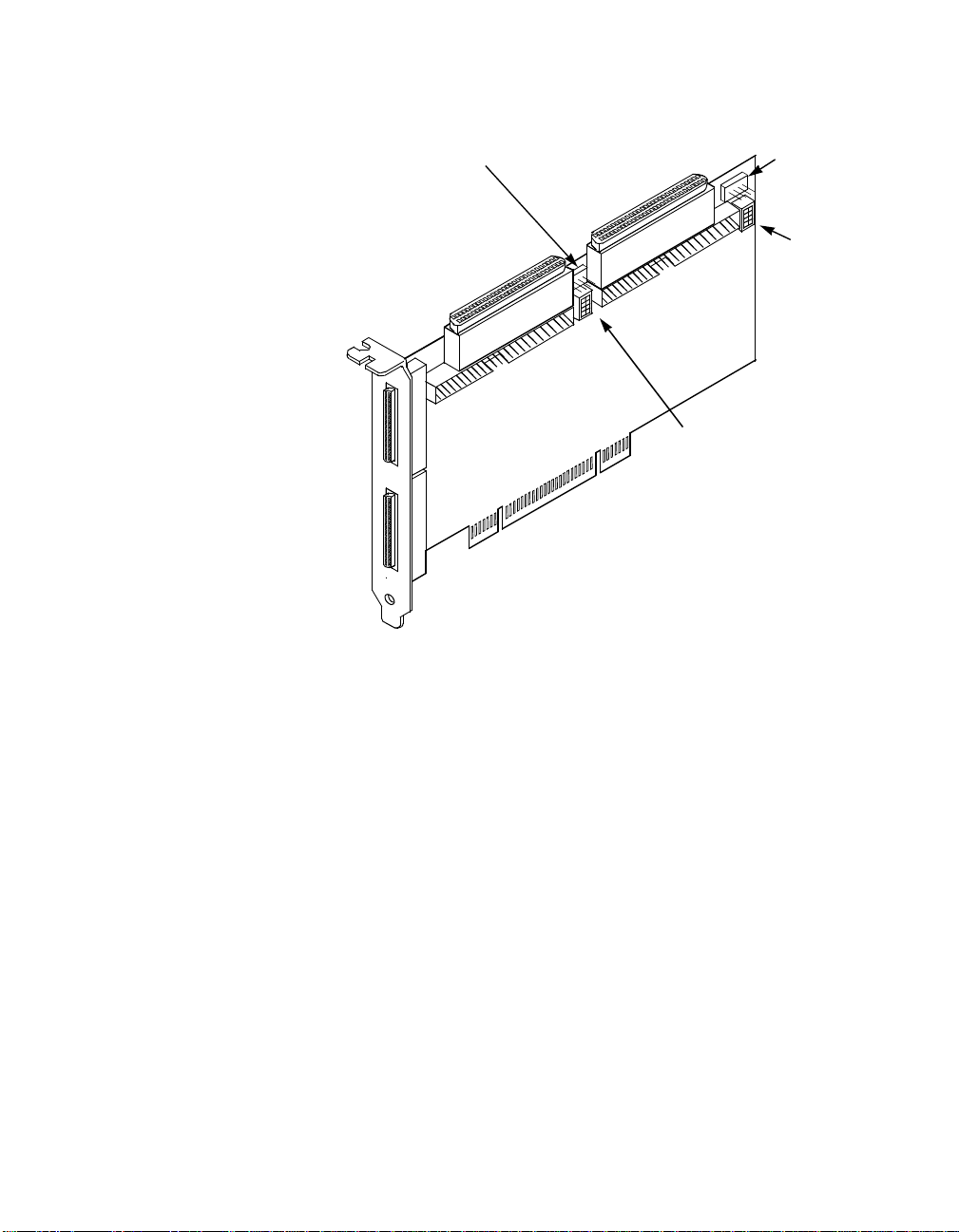
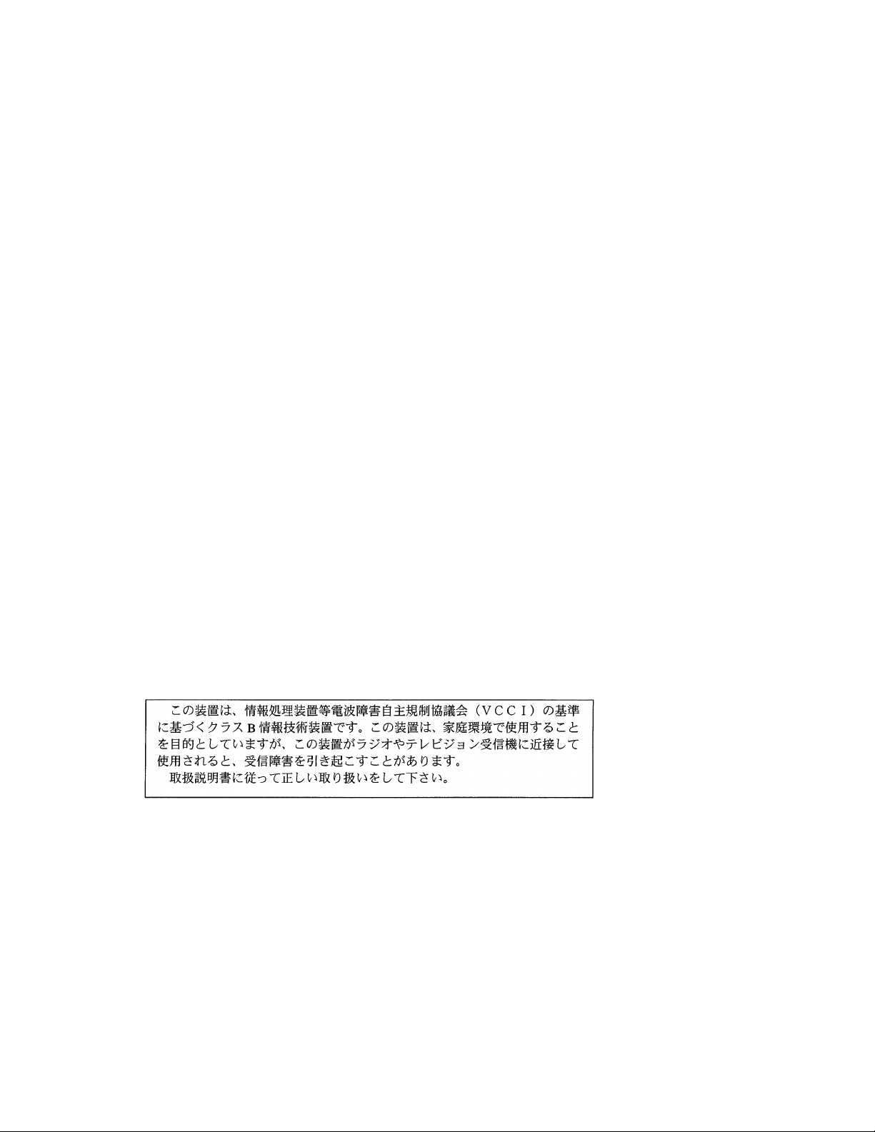
Figure 2.1 Hardwa re Connections for the SYM2 2801 Host Adapter
Channel A
LED Connector
J5
Channel A
68 -p in In te rn a l
High Density
SCSI Interface
J2
Channel B
68 -p in In te rn a l
High Dens ity
SC S I In te rfac e
J6
Channel B
50-pin Internal
Low Density
SCSI Interface
J8
Channel B
LED Connecto
J9
Channel B
Termination
Override
Switches
U2
Channel A
68-p in Ex tern al
VHDCI
SCSI Interface
Channel B
68-p in Ex tern al
VHDCI
SCSI Interface
J3
J7
Channel A
50-pin Internal
Low Density
SCSI Interface
J4
SYM22801 to PCI Bus
Connector on Mainboard
J1
Channel A
Termination
Override
Switches
U1
Step 6. Carefully insert the ed ge connector J1 (see Figure 2.1) of the
host adapter into the P CI slot. Make sure the edg e connector
is properly engaged b efore pressing the board i nto place as
shown in Figure 2.2.
Step 7. To plan on hooking up another host adapter on the same bus
as this host adapter, or an 8-bit device on 68-pin connector, see
the Channel Switches section discussed later in this chapter.
Notice that the components on a PCI host adapter face the opposite way
from those on other no n-PCI adapter boards you h ave in your system.
This is correct, and the bo ard is keyed to go in only one way.
Detailed Installation Procedure 2-5
Page 20
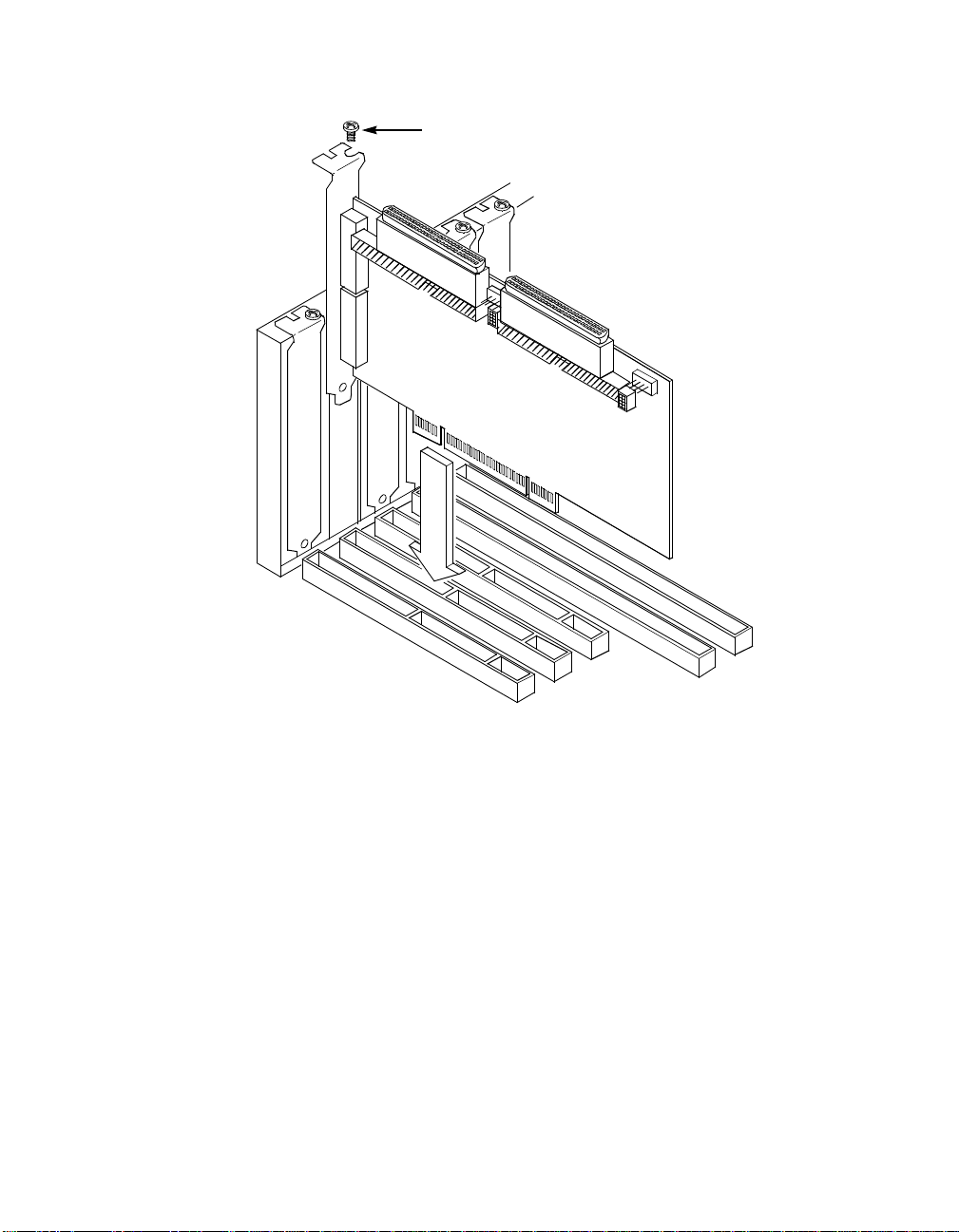
Figure 2.2 Inserting the Host Adapter
Bracket Screw
Step 8. The bracket around the conn ectors J3 and J7 (see Fig ure 2.1)
should fit where you re moved the blank panel. Secure it with
the bracket screw (see Figure 2.2) before making th e internal
and external SCSI bus connections.
2.2.3 Connecting the SCSI Peripherals
SCSI bus connections to the SYM22801 host a dapter inside the
computer are made w ith an un shiel ded, 68 or 50- conduct or ri bbon cabl e
(see Figure 2.3). One side of thi s cab le i s mar ke d with a c ol or to indicate
the pin-1 side. Somet imes the connectors on this cable are keyed to
ensure proper pin-1 connection.
2-6 Installing the SYM22801 Host Adapter
Page 21
All external SCSI b us connections to the SY M22801 host adapter are
made with shielded, 68-c onductor cables (see Fig ure 2.3). The
connectors on thi s cable are always k eyed to ensure proper pin- 1
connection.
Figure 2.3 SCSI Cables
SCS I Cables for Internal Connections
68-pin
High Density
and/or
50-pin
Low D ensity
SCS I Cable for External Connections
68-pin
VHDCI
Important:
You can connect up to six teen SCSI and Fast SCSI
devices, including th e host adapter board, on a s ingleended SCSI bus onl y if they are at least .3 m apart on a 6
meter cable. For Ultra S CSI, you can connect up to eight
devices, including th e host adapter board, on a
single-ended Ultra S C SI bu s on ly if the y are e ven ly sp ac ed
on a 1.5 meter Ultra SCSI cabl e (0.19m betw een device s).
You can connect up to fou r devices if they are evenly
spaced on a 3 meter Ul tra SCSI cable (0.75m be tween
devices). Your single-ended SCSI bus sho uld not exceed
Detailed Installation Procedure 2-7
Page 22

3 meters (total internal and external cable lengths), even
with fewer than four dev ices. The SYM22801
autotermination sch eme is designed to opera te properly
when plugging the end connector of the SC SI cables into
the SYM22801 SCSI c onnectors.
If you connect the SYM22801 in the middle of the bus, you
will incur improper ter mination since the swi tches are not
assigned on that bus c orrectly. Refer to the Channel
Switches section fo r more information.
2.2.4 Making Internal SCSI Bus Connections
This section provides step-by-step instructio ns about making internal
SCSI bus connecti ons:
Step 1. If you are connecting an internal Wide SCSI d evice, plug the
68-pin connector on on e end of a wide internal SCS I ribbon
cable into the connec tor J2, or J6 (see Figure 2.4). Make
certain to match pin-1 on both connectors.
2-8 Installing the SYM22801 Host Adapter
Page 23
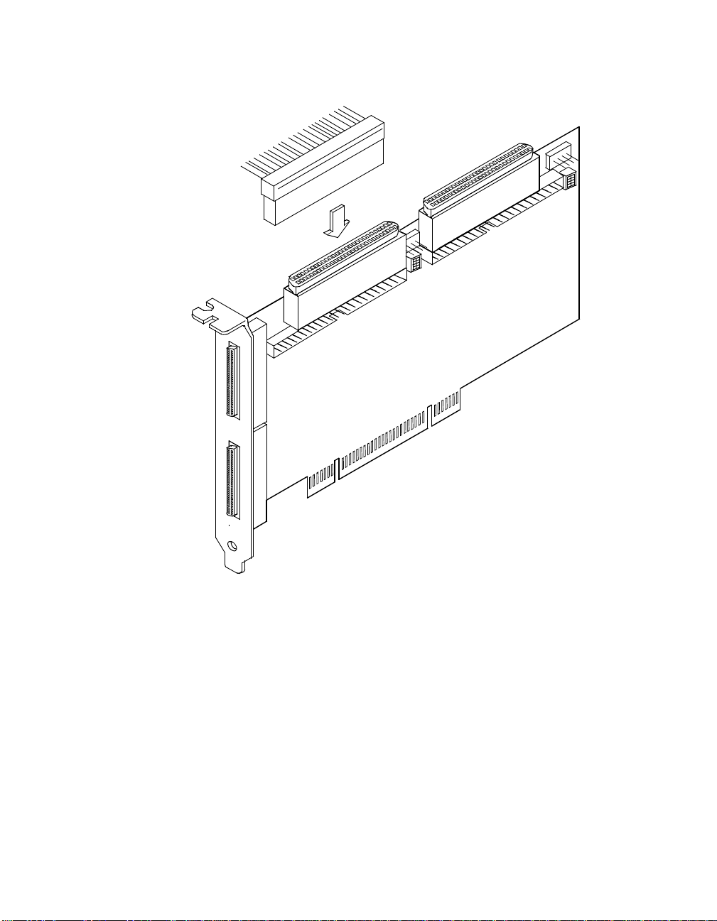
Figure 2.4 Internal Wide SCSI Ribbon Cable to Host Adapter
Connection
J6
J2
Step 2. To connect an 8-bit intern al SCSI device, plug the 50-pin
connector on one e nd of an 8-conductor internal SCSI ribbon
cable into the connector J4 or J8 (see Figure 2.5). Make certain
to match pin-1 on both c onnectors.
Detailed Installation Procedure 2-9
Page 24
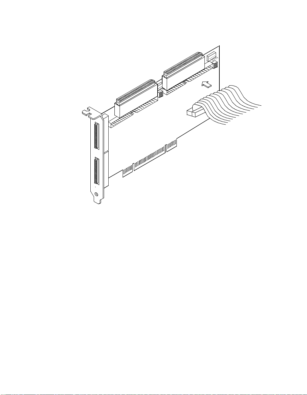
Figure 2.5 Internal SCSI Ribbon Cable to Host Adapter
Connection
Channel B
J8
Channel A
J4
Step 3. Plug the 68 or 50-pin connect or on the other end of the internal
SCSI ribbon cable into the SCSI connector on the internal SCSI
device. An example of this connection is shown in Figure 2.6.
You must match pin-1 on all c onnections.
2-10 Installing the SYM22801 Host Adapter
Page 25

Figure 2.6 Internal SCSI Ribbon Cable to Internal SCSI Device
Connection
Step 4. Additional inter nal SCSI devices are p lugged in by using an
internal SCSI ribbo n cable with the required nu mber of
connectors attac hed along its length as s hown in Figure 2.7.
An example of this type of chained conne ction is shown in
Figure 2.8. Make sure to match pin-1 on all co nnections.
Detailed Installation Procedure 2-11
Page 26

Figure 2.7 Connecting Additional Internal SCSI Devices
2-12 Installing the SYM22801 Host Adapter
Page 27

Figure 2.8 Multiple Internal SCSI Devices Chained Together
Step 5 . It is also possi ble to use both internal c onnectors on a channel
if you do not attach any external devices to that c hannel. An
example of this confi guration is shown in Figure 2.9.
Detailed Installation Procedure 2-13
Page 28

Figure 2.9 Using Both Internal Connectors on a Channel
Note:
When two connectors are already used on a chan nel, the
third connector ca nnot be used.
Step 6. Most PC cabinets ar e designed with a front pane l LED
(sometimes already con nected to an existing IDE drive). You
may connect this LE D cable to the host adapter, as shown in
Figure 2.10. This causes the front panel LED to indicate activity
on the SCSI bus.
This connector is not keye d. The orientation of the LED cable
does not matter as lon g as all four pins are con nected.
2-14 Installing the SYM22801 Host Adapter
Page 29

Figure 2.10 SCSI LED Connectors
Some LED cables have only two wi res. In this ca se, plac e the con nector
on one end or the other of J5 or J9. If the LED does not light during SCSI
bus activity from this host adapter, you may have to rotate the LED cable
180° on J5 or J9. See Table A.5 for pin descriptions.
2.2.5 Making External SCSI Bus Connections
This section provides step-by-step instructio ns about making internal
SCSI bus connecti ons:
Step 1. To connect external SCSI devices to the SYM22801 host
adapter, plug the 68-pin connector on o ne end of a shielded
external SCSI VHDC I cable (see Figure 2.3) into the h ost
adapter connector J3 o r J7 (see Figure 2.1).
This connector is now bra cketed to the back panel o f your
computer. Figure 2.11 shows how this connec tion is made.
Detailed Installation Procedure 2-15
Page 30
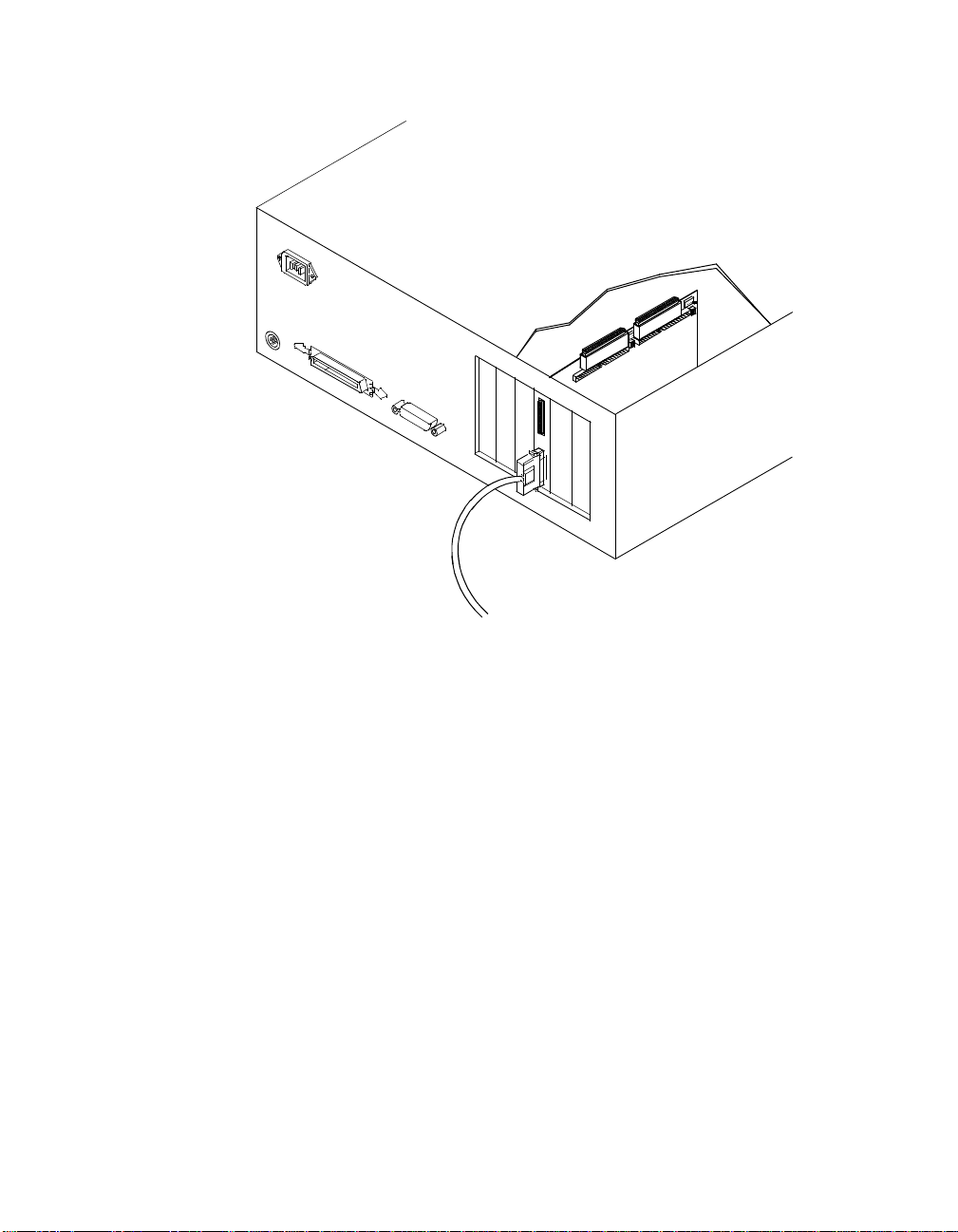
Figure 2.11 External Cable to Host Adapter
Step 2. Plug the 68-pin c onnector on the other end o f the shielded
external SCSI cable into the SCSI connector on yo ur external
SCSI device. An exa mple of this connection is shown in
Figure 2.12.
2-16 Installing the SYM22801 Host Adapter
Page 31

Figure 2.12 External Cable to External SCSI Device
Step 3. To connect more than one external SCSI device to the host
adapter, you must chain them together wi th shielded external
SCSI cables. An exa mple of these chained connec tions is
shown in Figure 2.13.
Detailed Installation Procedure 2-17
Page 32

Figure 2.13 Multiple External SCSI Devices Chained Together
2.3 SCSI Bus Termination
The devices making u p the SCSI bus are con nected serially (cha ined
together) with SCSI cables. The first and last physical SCSI devi ces
connected on the ends of the SCSI bus mus t have a set of resisto rs
called terminators. A ll other SCSI devices on t he bus must have their
terminators removed or disabled.
Remember:
2-18 Installing the SYM22801 Host Adapter
The SYM22801 host adapte r is also on the SCSI bus ; its
terminati on i s aut oma tic ally enab led when it is conn ect ed t o
the end of the bus.
Page 33

The peripheral device ter minators are usually set with ju mpers, resistor
modules, or with a switc h on the peripheral. Refer to the peripheral
manufacturer ’s instructions and to the user ’s manual
for information on how to identify the terminator setting of each device
and how to change it.
for your computer
Caution:
The SYM22801 senses S CSI devices by detecting the gr ound signal on
pin-22 of a 50-conducto r internal SCSI ribbon cable, or pin-50 of an
internal or external 68-conductor SCSI cable. If you use an adapter to
connect 8-bit devic es externally with a 50- conductor SCSI cable, the
ground signal is detec ted on pin-34.
The SYM22801 automatic ally covers SCSI bus termination for five
different bus configur ations, dependin g on the use of the c onnectors on
the SYM22801 host adapter (see Figure 2.1). The five bus configurations
are:
•
Only for internal SCS I connections,
•
Only for external SCSI connections,
•
For both internal and e xternal SCSI connections,
•
For connections to bo th internal connectors, an d
The auto-enable/disable se ns ing featur e on the SY M22 801
may enable termination erroneously if it is directly cabled to
another SCSI device or host adapter using the s ame
sensing method. Thi s is dealt with by prope rly setting the
termination overrid e swi tches U1 or U2 (see Fi gure 2.1) as
explained in this s ection under making an internal
connection with an other SYM22801.
•
For an internal connection to another SYM 22801, or an y connectio n
to a device using the same sensing method for automatic termination
as your SYM22801.
2.3.1 Internal SCSI Connections
If only internal SCSI devic e connections to the host adap ter have been
made, you must terminate the last internal dev ice on the SCSI bus. You
must disable the termination on all other devices. Termination on the host
adapter is automatic ally enabled in this case.
SCSI Bus Termination 2-19
Page 34

Figure 2.14 shows an exam ple of how term ination is deter mined for this
SCSI bus configurati on.
Figure 2.14 Internal SCSI Device Termination
2.3.2 External SCSI Connections
If only external SCSI devi ce connections to th e host adapter have bee n
made, you must terminat e the last exter nal de vice on the SC SI bus. You
must disable the termination on all other devices. Termination on the host
adapter is automatic ally enabled in this case.
Figure 2.15 shows an exam ple of how term ination is deter mined for this
SCSI bus configurati on.
2-20 Installing the SYM22801 Host Adapter
Page 35

Figure 2.15 External SCSI Device Termination
Last Device
on Chain -
Termination
Enabled
Does Not
End Ch ain Termina tion
Disabled
Host Adapter
Automatically
Terminated
2.3.3 Internal and External SCSI Connections
If you have internal a nd external SCSI device c onnections to the host
adapter, you must terminate the las t i nte rnal an d e xte rn al de vices on the
SCSI bus. You must disable the terminatio n on all other devices.
Termination on the host adap ter is automatically d isabled in this case.
Figure 2.16 shows an exam ple of how term ination is deter mined for this
SCSI bus configurati on.
SCSI Bus Termination 2-21
Page 36

Figure 2.16 Internal and External SCSI Device Termination
Last Device
on Chain
Termination
Enabled
H o s t Ad a pte r
Termination
A u t o mat ic a lly
Disabled
Last Device
on Chain
Termination
Enabled
2.3.4 Internal SCSI Connections for Both Internal Connectors
If you have internal SCS I devi ce co nnecti on s to both internal connec tors
of a channel, you mus t te rm in ate the int er nal de vi ce s o n each end of the
SCSI bus. You must disable the terminatio n on all other device s.
Termination on the host adap ter is automatically d isabled in this case.
Does Not
End Chain
Termination
Disabled
Caution:
Remember, you must not use the ex ternal connecto r for a
channel if you use bo th internal connectors for th at
channel.
2-22 Installing the SYM22801 Host Adapter
Page 37

Figure 2.17 shows an exam ple of how term ination is deter mined for this
SCSI bus configur ation. If you connect th e SYM22801 in the midd le of
the bus, you will incur improper termination si nce the switches are not
assigned on that bu s correctly.
Figure 2.17 Internal and Internal SCSI Device Termination
Last Devices
on Chain -
Termination
Does Not
End Chain -
Termination
Disabled
Enabled
If you have an interna l connection to another SYM 22801 host adapter,
or any connection to a device that uses the same sensing method for
automatic terminatio n as your SYM22801, you must properly set the
termination override switches U1 or U2 (see Figu re 2.1).
2.3.4.1 Channel Switches
When connecting anoth er SYM22801, you must tu rn on the switch for
the connector used on one or both of the board s. Please refer to
Figure 2.18, and the next two p aragraphs, to determine the correct
switch setting.
SCSI Bus Termination 2-23
Ho st A da pte r
Automatically
Terminated
Page 38

Four switches for ea ch channel provide cable detection simu lation and
forced upper line te rmination. Switch one simulates a device on the
internal 50-pin connec tor, switch two simulates a device on the in ternal
68-pin connector, switch three forces th e upper SCSI line termin ator to
stay on, and switc h four simulates a devi ce on the external 68-pi n
connector.
When SYM22801 is in the middle of a bus u sing only one connector,
then switch Int68 a nd Ext6 8 (switch es 2 an d 4) fo r that bus are on. This
forces the terminators fo r that bus to be disabled.
2-24 Installing the SYM22801 Host Adapter
Page 39

Figure 2.18 Termination Override Switch Settings for U1 and U2
g
y
p
g
g
y
p
g
g
p
y
p
g
g
1-INT50
2-INT68
3-UPPER TERM
4-EXT68
1
2
3
4
1
2
3
4
1
2
3
4
1
2
3
4
1
2
3
4
NO
De fault setting. Au to te rmin at io n w ill
work as desi
Simulates a dev ice on the Internal 50 pin
NO
connector. Use this switch onl
device is connected to the internal 50
connector that does not
like another LSI Lo
Simulates a dev ice on the Internal 68 pin
NO
connector. Use this switch onl
device is connected to the internal 68
connector that does not
like another LSI Lo
Forces termination ON the upper data
NO
lines . U s e th is s w itc h whe n a n ar ro w 8- b it
device is connected to one of the 68
connectors.
Simulates a device o n the Ex ternal 68 pin
NO
connector. Use this switch onl
device is connected to the external 68
connector that does not
like another LSI Lo
ned.
ic host adapter.
ic host adapter.
ic ho s t a d apter.
round pin 22,
round pin 50,
round pin 50 ,
when a
when a
when a
in
in
in
in
2.3.5 Setting SCSI IDs
You must set each SCSI device and the host adapter to a separate SCSI
ID, 0 through 15. SCSI ID 7 is the preset host adapter s etting, giving it
the highest priority o n the SCSI bus. If you pla n to boot your computer
from a SCSI hard dis k drive on the SCSI bus, that drive should have
SCSI ID 0, or the lo west SC SI ID o n the bu s. Chap ter 3, Con figuring the
Host Adapter, explains how to set the host adapter ID using the Symbios
SCSI Configuration uti lity.
SCSI Bus Termination 2-25
Page 40

The peripheral device SCSI IDs are usually set with j umpers or with a
switch on the peri pheral. Refer to the perip heral manufacturer ’s
instructions and to t he us er’s manual for y our com put er to determine the
ID of each device and h ow to change it. You must have no duplication
of SCSI IDs on a SCSI bus.
Step 1. Determine the SCSI ID of ea ch device on the SCSI bu s. Note
any duplication s and if 8-bit S CSI devices ar e to be used, the
host adapter ID must not be set above 7.
Step 2. Make any neces sary changes to the S CSI IDs and record the
IDs for future reference. Th e following table is prov ided as a
place to keep this record.
Table 2.1 SCSI ID Record
SCSI ID SCSI Device
15
14
13
12
11
10
9
8
7 SYM22801 Host Adapter (default)
6
5
4
3
2
1
0
2-26 Installing the SYM22801 Host Adapter
Page 41

2.4 Setting Interrupts
You should not normally have to change the de fault interrupt routi ng for
the SYM22801, since p erformance is usually inc reased by having two
separate interrupts. H owever, if your system does not suppor t two
separate interrupts, j umper TP9 (see Figure A.1) i s provided to change
the interrupt routing. The following table explains the jumper settings:
Table 2.2 Setting Interrupts
Jumper
Setting Condition
Jumper Out
(default)
Jumper In INTB/ is rerouted at power up to INTA/ on the
INTB/ is routed to INTB/ on the PCI bus
PCI bus
Setting Interrupts 2-27
Page 42

2.5 Completing Your Installation
Before replacing th e cover on your compu ter, review this installation
procedure check list. This will save you effort later.
Verify Installation Procedures Done
Host adapt er connect ion in PCI bus slot secure
Internal SCSI bus connections secure (pin-1 continuity)
External SCSI bus connections secure
Proper SCSI bus termination established
Unique SCSI IDs set and recorded for each device
Step 1. Replace the cabinet c over on your computer.
Step 2. Plug in all po wer cord s, and sw itch on pow er to all devic es and
your computer.
Step 3. Wait for your computer to boot up.
Step 4. To change the configuratio n of your host adapter, see
Chapter 3, Configuring the Host Adapter.
Step 5. Finally, refer to the
PCI SCSI Device Mana gement System
SDMS 4.0 User’s Guide
to use) to load the driver software for your particular oper ating
system.
2-28 Installing the SYM22801 Host Adapter
(or the guide fo r the s oftw ar e y ou pl an
Page 43

Chapter 3
g
Confi
This chapter discu sses how to change config uration settings and
includes these to pics:
•
Section 3.1, “When to Configure the SYM22801 Host Adapter,”
page 3-1
•
Section 3.2, “Sta rting the SCSI BIO S Configuration Ut ility,” page 3-2
•
Section 3.3, “Exi ting the SCSI BIOS Configuration Utility,” page 3-13
uring the Host Adapter
3.1 When to Configure the SYM22801 Host Adapter
In most cases you shou ld not need to change the d efault configuration
of your host adapter. You may decide to alter these default values if there
is a conflict between d evice settings, or if you need to optimize system
performance.
The following tables li st the configuration settings you can ch ange. The
global settings affect your host adap ter and all SCSI devices which are
connected to it. The d evice settings affect only ind ividual SCSI devices.
Table 3.1 Global Default Settings
Settings for the Host Adapter and All Devices Default Settings
SCAM Support Off
Parity Checking Enabled
Host Adapter SCSI ID 7
Scan Order Low to High
1. Applies to BI OS version 4.09 and late r.
Symbios SYM22801 Dual Channel PCI to Ultra SCSI Host Adapter 3-1
1
(0-Max)
Page 44

Table 3.2 Device Default Settings
Settings for Individual SCSI Devices Default Settings
Synchronous Transfer Rate (Mbytes/s) 40
Data Width 16
Disconnect On
Read/Write I/O Time-out (seconds) 10
Scan for Devices at Boot Time Yes
Scan for SCSI LUNs Yes
Queue Tags On
3.2 Starting the SCSI BIOS Configuration Utility
If you have SCSI BIOS ve rsion 4.xx, and it includes the Symbios SCSI
BIOS Configurati on Utility, you can change the default conf iguration of
your SCSI host adap ters. You may decide to alter these def ault v alues if
there is a conflict between device set tings or if you need to opti mize
system performance.
The version number of the S C SI B IOS appears in a banner displ ayed on
your computer mon itor during boot. I f th e u til ity is av ai la ble , the following
message also appear s on your monitor:
Press Ctrl-C to start Sy mbios Confi guration Ut ility...
This message remains on you r scree n for abou t five se conds, giving you
time to start the utility. If you decide to press “Ctrl-C,” the mes sage
changes to:
Please wait, invoking Sy mbios Confi guration Ut ility...
After a brief pause, your computer monitor displays the Main Menu of the
Symbios SCSI BIO S Configuration Utility.
NVRAM (Non Volatile Random Acc ess Memory) is availa ble on the
SYM22801 host adap ter. Changes can be made and stored to NV RAM
using this menu drive n utility.
3-2 Configuring the Host Adapter
Page 45

Important: This SCSI BIOS Configuration Utility is a powerful tool. If,
while using it, you somehow disa ble all of yo ur controllers ,
pressing Ctrl-A (or C trl-E on version 4.04 or la ter) after
memory initializa tion during r eboot allows you to r e-enable
and reconfigure.
Not all devices detected by the Configur ation Utilit y can be
controlled by the BI OS. Devices such as tape drives and
scanners require th at a device driver specifi c to that
peripheral be loade d. The device manufacturer p rovides
the device drivers.
3.2.1 Configuration Utility Main Menu
When you start the Symbios SCSI BIOS Con figuration Utility, the Main
Menu appears. This me nu displays a list o f up to four Symbios P CI to
SCSI host adapters in your system and info rmation about each of them.
The SYM22801 host adapte r appears o n the menu as two SY M53C875
entries; one for each channel . To select an adapter, use only the arrow
keys and enter key. Then, you can view and/o r change the current
settings for that adapt er and the SCSI devices attached to it.
You can select an adapt er only if Current Status is “On”. Changes are
possible since NVRAM is present on this host ada pter.
Here is an example of the Main Menu:
Main Menu
Port
Num
SYM53C875
SYM53C875
SYM53C895
Change Adapte r Status
Adapter Boot Order
Additional Ad apter Config uration
Display Mode = Verbose
Mono/Color
Language
Help
Quit
Starting the SCSI BIOS Co nfiguration Utility 3-3
FC00
F800
F801
Irq---------S tatus------- -NVRAM
Level Current Next-Boot Found
9
9
9
On
On
On
On
Off
Off
Yes
Yes
Yes
Page 46

Below the list of host adapters on the Main Menu display, you see eight
options. They are described in deta il below. If these settings are altered,
the system will reboot after the Qu it option is selected, wh ich allows the
user to exit from the Conf iguration Utility.
3.2.1.1 Change Adapter Status
The change adapter stat us allows the user to activ ate or deactivate a
host adapter and all S CSI devices attached to it. W hen this option is
used to make a change , the c hange t akes place aft er a r eboot upon exi t
from the utility. Here is an example of the Change Status on Next Boot
Menu:
Main Menu
Change Status on Next Boo t:
SYM53C875
SYM53C875
SYM53C895
To change an adapter's statu s, select it and press Ent er. Press the
Escape (Esc) key to exit from this menu.
3.2.1.2 Adapter Boot Order
The adapter boot order all ows the user to set the or der in which host
adapters will boot when you have more than o ne LSI Logic host adapte r
in your system. Wh en this option is sel ected, the Boot Order m enu
appears. Here is an exa mple of the Boot Order M enu:
Main Menu
BootSeq Bus DevFunc BootSeq Bus DevFunc
0 SYM53C875 00 A0 1 SYM53C875 00 98
Port
Num
FC00
F800
F801
Irq---------S tatus------- -NVRAM
Level Current Next-Boot Found
9
9
9
On
On
On
On
Off
Off
Yes
Yes
Yes
2 SYM53C895 00 90
3-4 Configuring the Host Adapter
Page 47

To change an adapter's bo ot order, select it and press Enter. You are
then prompted to enter t he new boot sequence num ber. To remove an
adapter's boot order, press Enter again rather than entering a new
sequence number. While the maximum capacity is 32 adapters, only four
adapters can be assign ed a boot order starting wit h boot sequence
number zero (0). If an invalid number is entered , an error message
appears. When the adapt ers are ordered as desired , press the Escape
(Esc) key to exit from thi s menu.
3.2.1.3 Additional Adapter Configuration
The additional adapter configuration allows the user to configure an
adapter that is not as signed a boot order. When this option is selected,
the Adapter Configura tion menu appears. Here i s an example of the
Adapter Configuration Menu:
Main Menu
BootSeq Bus DevFunc BootSeq Bus DevFunc
1 SYM53C875 00 A0 0 SYM53C875 00 98
SYM53C895
Highlight the adapter to be configured and press E nter. The message
“Resetting Adapter, Please wait” appears, and th en the syste m sc an s for
devices. Finally, the Utilities Menu appears an d lists the available
options, which are described belo w.
3.2.1.4 Display Mode
The Display Mode option dete rmines how much information ab out your
host adapters and SCSI devices appear on your computer monitor during
boot. For more complete infor mation, choose the v erbose setting. For a
faster boot, choose th e terse setting.
3.2.1.5 Mono/Color
The Mono/Color option allows a choic e between a monochr ome or color
display for the SCS I BIOS Configuration Util ity. You might need to
choose the mono/co lor setting to get a more re adable screen on a
monochrome monitor.
Starting the SCSI BIOS Co nfiguration Utility 3-5
Page 48

3.2.1.6 Language
If enabled, the Languag e opt ion al lows you to select from five lan guages
for the configuration uti lity: English, German, Fr ench, Italian, and
Spanish.
3.2.1.7 Help
The Help option allows the user to bring up a help screen with
information about t he Main Menu.
3.2.1.8 Quit
The Quit option allo ws exiting from the SCS I BIOS Configuration Ut ility
when the Main Menu is displayed.
3.2.1.9 Esc
The Esc option allows ex iting fr o m al l th e s cree ns except the Main Menu.
3.2.2 Utilities Menu
When you select a host adapter on the Mai n menu, the Utilities me nu
appears as shown below:
SYM53C875
Adapter Setup
Device Selection s
Help
Exit this men u
Choose Adapter Setup to view and change the selected adapter settings.
Choose Device Selecti ons to view and change set tings for the devices
attached to the se lected adapter.
You are returned to this menu after making ch anges to the con figuratio n
of any host adapter or c onnected SCSI device. Be fore you exit this
menu, you are prompte d to save or cancel any changes.
3-6 Configuring the Host Adapter
Page 49

3.2.2.1 Adapter Setup Menu
When you select Ad apte r Setup, the correspondi ng m enu ap pea rs. Here
is an example of the A dapter Setup Menu:
Adapter Setup
SCAM Support Off Parity Enabled Host SCSI ID 7 Scan Order Low to High < 0..Max> Removable Med ia Support None CHS Mapping SCSI Plug & P lay Mapping Spinup Delay (sec) 2 Help Restore Defau lt Setup Exit this men u
The settings in this me nu a re gl obal s etti ngs th at affe ct t he sel ec ted h os t
adapter and all SCSI d evices attached to it. One o f these choices can
be selected by highl ighting it and pressing En ter.
SCAM Support – The Symbios BIOS v ersion 4.xx and a bove s upports
the SCSI Plug and Play protocol called SCAM ( SCSI Configured
AutoMatically). SCA M support b y defaul t is off in adapt er BIO S versions
4.09 and later fo r the SYM5 3C876 dev ice. The us er may c hoose to turn
this on only if the sy stem drivers do not req uire SCAM off. Note that if
this BIOS is flashed onto a board with existing se ttings, then these
settings will not be changed to reflect the new BIOS defaults. Go into the
Configuration Utility to change these settings .
Parity – The Symbios PC I to SCSI host adapters always generate
parity, but some older SCSI devices do no t. Therefore, you are offered
the option of disabl ing parity checking.
Starting the SCSI BIOS Co nfiguration Utility 3-7
Page 50

Note: When disab ling parity checking, it is also necessary t o
disable disconn ects for all devices, as parity checking for
the reselection phase is not disabled. If a device does not
generate parity, and it disconnects, the I/O never completes
because the rese lection never complete s.
Host SCSI ID – This option refers to th e ho st adapter’s SCS I ID, whi ch
is a unique number us ed to identify the devic e on the SCSI bus.
Note:
Scan Order – This opt ion allows the user to tel l the SCSI BIOS and
device drivers to sca n the SCSI bus from low to high (0 to max) SCSI
ID, or from high to low (ma x to 0) SCSI ID. If there is more than one
device on the SCSI bus, chang ing the scan order changes the ord er in
which drive letters are assigned by the system. Dr ive order may be
reassigned differently in s yst ems su ppo rt ing the B IO S B oo t Sp ec ifi cat io n
(BBS).
See the
Chapter 2, “SCSI B IOS” for additional infor mation regarding BBS.
Note:
Removable Media Support – This option defines the removable media
support for a specific drive. When this option i s selected, a window
appears with three c hoices:
In general, it is suggested that the user not change the host
adapter ID from the defau lt value of 7, as this gives it the
highest priority o n the SCSI bus. Please also note that if
you have 8-bit SCSI devices (narrow), they cannot see host
IDs greater than 7.
PCI SCSI Device Management System SDMS 4.0 User’s Guide
This scan order option may conflic t with operating syste ms
that automatically as sign a drive order.
,
•
None
•
Boot Drive Only
•
With Media Install ed
None indicates there is no removable media su pport whether the driv e
is selected in B BS as being first, or fir st in scan order in no n-BBS.
Boot Drive Only provides removabl e media support for a remov able
hard drive if it is fi rst in the scan order.
3-8 Configuring the Host Adapter
Page 51

With Media Installed provides removab le media support wherever the
drive(s) actually reside s.
One of these choic es can be selected by highlighting it and pr essing
Enter.
CHS Mapping – This option defines the cylinder head sector (CHS)
values that will be ma pped onto a disk without pr e-existing partition
information. SCSI Plug and Play Mapping is th e default value.
To support interchange wi th non-compatible sys tems, there is another
option that can be selected by choosing CHS Mapping and then
cursoring to “Alterna te CHS Mapping”.
Note:
To remove partitioning, tw o options are available :
•
Reformat the disk using the Forma t Device option. See the “Device
Selections Menu” sec tion below for further detai ls regarding this
option.
•
Use the FDISK /MBR comma nd at the C:\ prompt, where MBR
represents master bo ot record.
Important:
Spinup Delay (seconds) – This option allows the user to st agger spin
ups for a longer perio d of time to balance the to tal current load. The
default value is 2 seconds with choices between 1 and 10 seconds .
Neither of these options will ha ve any effect after the disk
has been partitioned with the FDISK command.
Reformatting the disk or using FDISK /MBR erases all
partitioning and data tha t exists. Be careful th at you target
the correct disk when using ei ther the Format utility or the
FDISK /MBR command.
After clearing the p artitions and data, it is necessary to
reboot and clear memor y or the old parti tio ni ng d ata w il l be
reused, thus nullifyi ng the previous operation.
This is a power manage ment device designed to a ccommodate disk
devices that may have h eavy current load durin g power up. If multiple
drives are being pow ered up simultan eously and draw ing heavy curre nt
loads, then this optio n staggers the spin ups to limit start-up current.
Starting the SCSI BIOS Co nfiguration Utility 3-9
Page 52

3.2.3 Device Selections Menu
When you select t he Device Se lections o ption, the cor responding m enu
appears:
Device Select ions 0-7
Sync Data Disc Time Scan Queue Initial
Rate Width Out Bus LUNS Tags Boot
0-Dev0 N/A 40 16 On 10 Yes Ye s On No
1-Dev1 N/A 40 16 On 10 Yes Ye s On No
2-Dev2 N/A 40 16 On 10 Yes Ye s On No
3-Dev3 N/A 40 16 On 10 Yes Ye s On No
4-Dev4 N/A 40 16 On 10 Yes Ye s On No
5-Dev5 N/A 40 16 On 10 Yes Ye s On No
6-Dev6 N/A 40 16 On 10 Yes Ye s On No
SYM53C875 40 16 On 10 Yes Yes On No
Device Select ions 8-15
Help
Exit this menu
The settings in this men u affect individual SCS I devices attached to th e
selected host ad apter. Changes made from this me nu do not cause the
system to reboot upon e xit from the SCSI BI OS Configuration Ut ility. To
change a value, select th e required device by using the ar row keys and
press Enter. A new menu appears provi ding the options and utilit ies
available. For example, you could select the S ync R ate option to change
the Sync Rate valu e of the chosen devic e
3-10 Configuring the Host Adapter
Page 53

.
g
g
g
g
SYM53C875
Inside device
Sync Rate
Width
Disconnect
Read/Write I/ O Timeout
Scan for Devi ce at Boot T ime
Scan for SCSI LUNs
Queue Tags
Initial Boot
Format
Verify
Help
Restore Defau lt Setup
Exit this men u
Please review the descriptions of each option below before changing any
values.
Sync Rate (Mbytes/s) –
transfer rate the host adapter will attempt to ne
and a SCSI device mus t a
Width (bits) –
This option defines the maximum SCSI data width the
host adapter will attempt t o ne
device must a
ree to a width they can both handle. Only host adapters
This option defines th e maximum data
otiate. The host adapter
ree to a rate they can both handle.
otiate. The host adapter and a SCSI
that can do 16-bit d ata transfers have this optio n enabled.
Starting the SCSI BIOS Co nfiguration Utility 3-11
Page 54

Disconnect – SCSI devi ces have the ability to dis connect from the
initiator during an I/O transfer. This disconnect option frees the SCSI Bus
to allow other I/O processes. This opti on tells the host adapter whether
or not to allow a devic e to disconnect. Som e devices run faste r with
disconnects enabled (mostly newer d evices), whi le som e run fas ter with
disconnects disab led (mostly older dev ices).
Read Write I/O Time-out (seconds) – This option sets the amount of
time the host adapter waits for a read, write, or s eek command to
complete before trying the I/O transfer again. Sin ce this provides a
safeguard allowing th e system to recove r if an I/O operation fail s, it is
recommended that you always set the time-out to a value greater than
zero.
Note:
A zero value allows unlimited time for a n operation to
complete and coul d result in the system b eing hung-up.
Scan for Device at Boot Time – S et this option to “No” if th ere is a
device that you do not want to be available to the system. Also, on a bus
with only a few devi ces attached, you can speed up boot time by
changing this se tting to “No” for all unus ed SCSI IDs.
Scan for SCSI Logical Units (LUN s) – Set this option to “No” if
problems arise with a d evice th at res ponds to al l LUNs whether they are
occupied or not. For exa mple, if a SCSI device wi th multiple LUNs is
present on your system b ut you do not want all of th ose LUNs to be
available to the system , then set this option to “No.” This will limit the
scan to LUN 0 only.
Queue Tags – If the device driver has the capability, this option all ows
the user to enable or disable the issuing of q ueue tags during I/O
requests.
Initial Boot – This option allows any d evi ce attached to the first ad apte r
to become the boot devi ce. It provides the users of n on-BBS personal
computers with some of the flexibility of a BBS machine.
Format Device – If enabled, th is option allows the u ser to low-level
format a magnetic disk drive. Low-level formatti ng will completely and
irreversibly erase all data on the drive. Formatting will default the drive
to a 512-byte sector size even if the dr i ve had prev i ous ly b een for ma tted
to another sector size.
3-12 Configuring the Host Adapter
Page 55

Ver i fy – This option allows the us er to read all the sect ors on a disk
looking for errors. Wh en selected, this option displays the following
message:
“Verify all sectors on the device
Press ESC to abort
Else press any key to continue”
Help – This option brings u p a help screen with inform ation about the
Device Selections Men u.
Restore Default Setup – This option resets all device selections back
to their default se ttings. Select this op tion to restore all m anufacturing
defaults for the specifi ed adapter. Note that all user customized option s
will be lost upon savin g after restoring default s etup.
Exit this menu – This optio n allows the user to l eave the Device
Selections Menu and return to the previous sc reen.
3.3 Exiting the SCSI BIOS Configuration Utility
Since some changes on ly take effect after the syste m reboots, it is
important that the user exit from this SCSI BIOS Configuration Utility
properly. Return to the Main Menu and exit via the Quit option. Rebooting
the system without pr operly exiting from this uti lity may cause some
changes to not take effect.
Exiting the SCSI BIOS Configuration Utility 3-13
Page 56

3-14 Configuring the Host Adapter
Page 57

Appendix A
Technical Specifications
This section discusses the physical environme nt associated with the
SYM22801 Host Adapter. It includes a mechanical drawing of this board,
which is shown in Figu re A.1. It also includes thes e topics:
•
Section A.1, “Ph ysical Environment, ” page 1-1
•
Section A.2, “El ectrical Characterist ics,” page 1-2
•
Section A.3, “Operati onal Environment,” page 1 -3
A.1 Physical Environment
This section discusses the physical, electrical, thermal, and safety
characteristics of the SYM22801 Host Adapter boa rd. Additionally, this
board is compliant with electromagnetic stand ards set by the FCC.
A.1.1 Physical Characteristics
The dimensions of the SYM22 801 host adapter boa rd are 7.50” x 3.80”.
PCI connection is ma de through the edge conn ector J1. Internal 16-bit
SCSI connection is mad e through the 68-p in high dens ity connec tors J2
or J6. Internal 8-bit SC SI connection is made th rough the 50-pin low
density connectors J4 or J8. E xternal SCS I connection is made thro ugh
the 68-pin VHDCI connectors J 3 or J7. The J3 and J7 connectors
extend through the ISA /EISA bracket, which is a ttached to the face of
the connector outsid e the cabinet where the SY M22801 is installed.
The bracket is a standar d ISA type with a cutout to a ccommodate the
connectors. The J5 and J9 connectors are for connecting the computer’s
Busy LED. It i s a 4-pin o ne row right angle head er wired in p arallel with
the on-board LED. The component height on the top and bottom of the
board follows the P CI specification.
A-1
Page 58

Figure A.1 SYM22801 Me chanical Drawing
190.50(REF) (7.50(REF))
J3
96.52(REF) (3.80(REF))
J7
A.2 Electrical Characteristics
The SYM22801 maximum power requirements, in cluding SCSI
TERMPWR, under normal operation are as follows:
+ 5 V DC
5% 1.5 A Over the operating range 0–55 °C
±
J2
J4
TERMPWR
Fail L E D
SYM53C 876
J1
J5
U1
NVRAM
J6
NVRAM
TP9
J9
J8
TERMPW R
Fail LED
FLASH
EEPROM
U2
+ 12 V
+ 3.3 V
0.6 V 50 mA Over the operating range 0–55 °C
±
3 V 130 mA Over the operating range 0–55 °C
±0.
Under abnormal conditi ons such as a short on SCSI TERMPWR, + 5 V
current may be high er. At temperatures of at least 25
4 A is sustained no lon ger than 30 seconds befor e the self-resetting
TERMPWR short circuit pr otection device opens .
The PCI PRSNT1# and PRSNT2# pins are set to indicate a 15 W
maximum configurat ion.
A-2 Technical Specifications
when operating in a 3.3 V PCI slot
°
C a current of
Page 59

A.2.1 Thermal, Atmospheric Characteristics
The board is designed to operate in an environmen t defined by the
following parameters:
•
Te mperature range: 0–55 °C (dry bu lb)
•
Relative humidity r ange: 0–90% (noncondensing)
•
Maximum dew point tempe rature: 32 °C
A.2.2 Electromagnetic Compliance
The board is designed and implemented to minimi ze electromagnetic
emissions, susceptibi lity, and the effects of electr omagnetic discharge.
The board meets the requirements of FCC and CISPR Class B limits and
is marked with the FCC S elf Certification logo. It also carries the CE
mark.
A.2.3 Safety Characteristics
The bare board meets or e xceeds the requirements of UL flammability
rating 94 V0. The bare board is also marked with the supplie r ’s name or
trademark, type, and UL flamma bility ra ting. Since this board is instal led
in a PCI bus slot, all voltages are below the SE LV 42.4 V limit.
A.3 Operational Environment
The SYM22801 is desi gned for use in PCI comput er systems with an
ISA/EISA bracket type . The Symbios SDMS™ (SC SI Device
Management System) software operates the board, but the design of the
board does not preve nt the use of other software.
A.3.1 The PCI Interface
The PCI interface ope ra tes a s a 32-bit DMA bus mas ter. The connection
is made through the edge c onnector J1, which pro vides connections on
both the front and back of the board. The signal defini tions and pin
numbers conform to the P CI Local Bus Specific ation Revision 2.1
standard. The following tables show the signal a ssignments.
Operational Environment A-3
Page 60

Note: The + 3.3 V pins are tied toge ther and dec oupled with high
frequency bypass ca pacitors to ground. No cur rent from
these 3.3 V pins is used on the board. Th e PCI portion of
the SYM53C876 chip is powered from the 3 V/5 V p ins.
Table A.1 PCI Connector J1 (Front)
Signal Name Pin Signal Name Pin Signal Name Pin
−12 V 1 GND 22 +3.3 V 43
TCK 2 AD27 23 C_BE1/ 44
GND 3 AD25 24 AD14 45
TDO 4 +3.3 V 25 GND 46
+5 V 5 C_BE3/ 26 AD12 47
+5 V 6 AD23 27 AD10 48
INTB/ 7 G ND 28 GND 49
INTD/ 8 AD21 29 KEYWAY 50
GND (PRSNT1/) 9 AD19 30 KEYWAY 51
RESERVED 10 +3.3 V 31 AD08 52
GND (PRSNT2/) 11 AD17 32 AD07 53
KEYWAY 12 C_BE2/ 33 +3.3 V 54
KEYWAY 13 GND 34 AD05 55
RESERVED 14 IRDY/ 35 AD03 56
GND 15+3.3 V 36GND 57
CLK 16 DEVSEL/ 37 AD01 58
GND 17 GND 38 3 V/5 V 59
REQ/ 18
3 V/5 V 19 PERR/ 40 +5 V 61
AD31 20 +3.3 V 41 +5 V 62
AD29 21 SERR/ 42
1. Shaded signals are not connected.
LOCK/ 39 ACK64/ 60
1
A-4 Technical Specifications
Page 61

Table A.2 PCI Connector J1 (Back)
Signal Name Pin Signal Name Pin Signal Name Pin
TRST/ 1 AD28 22 PAR 43
+12 V 2 AD26 23 AD15 44
TMS 3 GND 24 +3.3 V 45
TDI 4 AD24 25 AD13 46
+5 V 5 IDSEL 26 AD11 47
INTA/ 6 +3.3 V 27 GND 48
INTC/ 7 AD22 28 AD09 49
+5 V 8 AD20 29 KEYWAY 50
RESERVED 9 GND 30 KEYWAY 51
3 V/5 V 10 AD18 3 1 C_BE0/ 52
RESERVED 11 AD16 32 +3.3 V 53
KEYWAY 12 +3.3 V 33 AD06 54
KEYWAY 13 FRAME/ 34 AD04 55
RESERVED 14 GND 35 GND 56
RST/ 15 TRDY/ 36 AD02 57
3 V/5 V 16 GND 37 AD00 58
GNT/ 17 STOP/ 38 3 V/5 V 59
GND 18 +3.3 V 39 REQ64/ 60
RESERVED 19 SDONE 40 +5 V 61
AD30 20 SBO/ 41 +5 V 62
+3.3 V 21 GND 42
1. Shaded signals are not connected.
1
Operational Environment A-5
Page 62

A.3.2 The SCSI Interface
The SCSI interface oper ates as 8-bit or 16-bit, sy nchronous or
asynchronous, single-ended bus, and s upports SCSI-2 protoc ols and
16-bit arbitration. The i nterface is made through c onnectors J2, J3 and
J4 for channel A. Cha nnel B connec tors are J6, J7, and J8. Connec tors
J2 and J6 are 68-pi n high density right angl e receptacles for internal
connections. Conn ectors J3 and J7 are 68-pin VHDCI right angle
receptacles that protru de throu gh th e bac k p anel br acke t. Connectors J4
and J8 are 50-pin low density vertical shrouded headers used for internal
SCSI connections.
Note:
Active single-en ded SCSI termination i s provided automatical ly. SCSI
termination power is also supplied by th e board. The following tab les
show the signal assi gnments for J2/J6, J3/J7, a nd J4/J8.
Up to two (and only two) con nections are a llowed on each
channel. Connecting to all three connectors on a channel
will result in an un reliable configuratio n.
A-6 Technical Specifications
Page 63

Table A.3 SCSI Connectors J2/J6 and J3/J7
Signal Name Pin Signal Name Pin Signal Name Pin
GND 1 GND 24 SD7/ 47
GND 2 GND 25 SDP/ 48
GND 3 GND 26 GND 49
GND 4 GND 27 CPRSNT_A-B/
GND 5 GND 28 TERMPWR 51
GND 6 GND 29 TERMPWR 52
GND 7 GND 30 N/C 53
GND 8 GND 31 GND 54
GND 9 GND 32 SATN/ 55
GND 10 GND 33 GND 56
GND 11 GND (J2/J6)
34 SBSY/ 57
GND/16CBLSNS
(J3/J7)
GND 12 SD12/ 35 SACK/ 58
GND 13 SD13/ 36 SRST/ 59
GND 14 SD14/ 37 SMSG/ 60
GND 15 SD15/ 38 SSEL/ 61
GND 16 SDP1/ 39 SC_D/ 6 2
TERMPWR 17 SD0/ 40 SREQ/ 63
TERMPWR 18 SD1/ 41 SI_O/ 64
N/C 19 SD2/ 42 SD8/ 65
GND 20 SD3/ 43 SD9/ 66
GND 21 SD4/ 44 SD10/ 67
GND 22 SD5/ 45 SD11/ 68
GND 23 SD6/ 46
1. CPRSNT_A/ (J2/J6) and CPRSNT_B/ (J3/J7) are used to sense the
connection of a standard SCSI dev ice by sens ing SCSI sta ndard GND on this
pin.
1
50
Operational Environment A-7
Page 64

Table A.4 SCSI Connectors J4/J8
Signal Name Pin Signal Name Pin
GND 1 SD0/ 2
GND 3 SD1/ 4
GND 5 SD2/ 6
GND 7 SD3/ 8
GND 9 SD4/ 10
GND 11 SD5/ 12
GND 13 SD6/ 14
GND 15 SD7/ 16
GND 17 SDP/ 18
GND 19 GND 20
GND 21 CPRSNT_C/
1
N/C 23 N/C 24
N/C 25 TERMPWR 26
N/C 27 N/C 28
GND 29 GND 30
GND 31 SATN/ 32
GND 33 GND 34
GND 35 SBSY/ 36
GND 37 SACK/ 38
GND 39 SRST/ 40
GND 41 SMSG/ 42
GND 43 SSEL/ 44
GND 45 SC_D / 4 6
GND 47 SREQ/ 48
GND 49 SI_O/ 50
1. CPRSNT_C/ is used to sense the connection of a standard
SCSI device by sensing SCSI standard GND on this pin.
22
A-8 Technical Specifications
Page 65

A.3.3 The LED Interface
The LED interface on the SYM22801 is a four-wire a rrangement that
allows the user to co nnect an LED harness to t he board. The
GPIO0_FETCH line (maximum output low voltage 0 .4 V and minimum
output low current 16 mA) is pulled low to compl ete the circuit when a
harness with an LED is attach ed. The connector s on the SYM22801 ar e
J5 and J9.
Table A.5 LED Connectors J5/J9
Signal Name Pin
LED+ 1 LED− 2 LED− 3 LED+ 4
Operational Environment A-9
Page 66

A-10 Technical Specific ations
Page 67

Appendix B
y
Glossar
of Terms and
Abbreviations
Address A specific location in memory, designated either numerica lly or by a
symbolic name.
Asynchronous Data Transfer
BIOS Ba sic Input/Output System . Software that provides bas ic read/write
Bit A binary digit. The smallest unit of i nformation a computer uses. Th e
Bus A colle ction of unbroken signa l lines across whic h information is
A method of transmis sion which does not requir e a common clock, but
separates fields of data by stop and start bit s. It is slower than
synchronous data tr ansfer.
capability. Usually kept as firmware (ROM ba sed). The sys tem BIOS on
the mainboard of a computer is used to boot and control the system. The
SCSI BIOS on your hos t adapter acts as an extensi on of the system
BIOS.
value of a bit (0 or 1 ) represents a two-way choi ce, such as on or off,
true or false, and so on.
transmitted from one p art o f a co mpu ter sy stem to a noth er. Connections
to the bus are made vi a taps on the lines.
Bus Mastering A high-performan ce way to transfer data. Th e host adapter controls the
transfer of data directly to and from system memory without bothering the
computer ’s microprocessor. This is the fastest way for multitasking
operating systems to tr ansfer data.
Byte A unit of i nformation consisting of e ight bits. Chain A topolo gy in which ev ery processor is connected to t wo others, e xcept
for two end processors th at are connected to onl y one other.
CISPR A special in ternational commi ttee on radio interferen ce (Committee,
International and Spec ial, for Protection in Rad io).
Glossary of Terms and Abbreviations B-1
Page 68

Configuration Refers to the way a compute r is set up; the combined hardware
components (compute r, monitor, keyboard, and peripher al devices) that
make up a computer s ystem; or the software setti ngs that allow the
hardware components to communicate with each other.
CPU Central Processing U nit. The “brain” of the comput er that performs the
actual computations. The term Mi cro Processor U nit (MPU) is also used .
DMA Direct Memory A ccess. A met hod of moving dat a from a storag e device
directly to RAM, without using the CPU’s resources.
DMA Bus Master
A feature that allows a peripheral to control the flow of data to and from
system memory by blocks, as opposed to PIO (Pro grammed I/O) where
the processor is in control and the flow is by byte.
Device Driver A program that allows a micropr ocessor (through the operating s ystem)
to direct the operation o f a peripheral device.
Differential A hardware configuration for connecting SCSI devices . It uses a pair of
lines for each signal transfer (as opposed to sin gle-ended SCSI which
references each SCSI signal to a common groun d).
Dword A double word is a group of 4 consecutive bytes or characters that are
stored, addressed, transmitted, and operated on as a unit. The lower two
address bits of the least s ignificant byte must equal zero i n order to be
dword aligned.
EEPROM Electronically-Era sable Programmable Re ad Only Memory. A memory
chip typically used to store configuration info rmation. See NVRAM.
EISA Extended Industry Standar d Architec ture. An e xtensio n of the 16- bit ISA
bus standard. It allo ws devices to perform 32-bi t data transfers.
External SCSI Device
A SCSI device installed outside the computer cabinet. These devices are
connected in a c ontinuous cha in using spe cific types of shielded cables .
Fast SCSI A standard for SCSI data tr ansfers. It allows a transfer rate of up to
10 Mbytes/s over an 8-bit SCS I bus and up to 20 Mbytes/s over a 16 -bit
SCSI bus.
FCC Federal Co mmunications Commiss ion. File A named col lection of information s tored on a disk.
B-2 Glossary of Terms and Abbreviations
Page 69

Firmware Software that is permanen tly stored in ROM. Therefor e, it can be
accessed during b oot time.
Hard Disk A disk made of metal and per manently sealed into a drive cartridge. A
hard disk can stor e very large amounts of information.
Host The computer system in which a SCSI host adapter is ins talled. It uses
the SCSI host adapter to transfer information to an d from devices
attached to the SC SI bus.
Host Adapter A c ircuit board or in tegrated circuit th at provides a SCS I bus connection
to the computer system.
Internal SCSI Device
A SCSI device inst alled inside the computer cabinet. Th ese device s are
connected in a con tinuous chain using an unshielded ribbo n cable.
IRQ Interru pt Request Channel. A path through which a device can get the
immediate attention of the computer’s CPU. The PCI bus assigns an IRQ
path for each SCSI hos t adapter.
ISA Industry Standard A rchitecture. A type of computer bus used in most
PC’s. It allows devices to send and rece ive data up to 16-bits at a time.
Kbyte Kilobyte. A measure of computer stor age equal to 1024 bytes. Local Bus A way to connect peripherals d irectly to computer memory. It bypasses
the slower ISA and EISA busses. PCI is a l ocal bus standard.
Logical Unit A subdivision, either logi cal or physical, of a S CSI device (actual ly the
place for the devic e on the SCSI bus). Mos t devices have only one
logical unit, but up to eight are allowed for each of the eight possible
devices on a SCSI bus.
LUN Logical Unit Number. An identifier, zero to seven, for a logi cal unit. Mbyte Megabyte. A measure of computer storage equal to 1024 kilobytes. Mainboard A large ci rcuit board that holds RAM, ROM, the microproces sor, custom
integrated circuits, an d other compon ents that make a c omputer work . It
also has expansion slots for host adapters and other expan sion boards.
Main Memory The part of a computer’s memory which is directly accessible by the CPU
(usually synony mous with RAM).
Glossary of Terms and Abbreviations B-3
Page 70

Motherboard Se e Mainboard. In some coun tries, the term Motherbo ard is not
appropriate.
Multi-tasking The executing of m or e th an one c omm and at the sa me tim e. Th is a llo ws
programs to operate in parallel.
Multi-threading The simultaneous accessing of data by more than one SCSI device. This
increases the da ta throughput.
NVRAM Non Volatile Random Acces s Memory. Actually an EEPROM
(Electronically-Erasable Programmable Read Only Memory chip) used to
store configuratio n information. See EE PROM.
Operating System
A program that organ izes the internal acti vities of the computer and its
peripheral devic es. An operating syste m performs basic task s such as
moving data to and fr om devi ces, an d managin g inform ation in memory.
It also provides the us er interface.
Parity Checking A way to verify the accuracy of data transmitted over the SCSI bus. One
bit in the transfer is used to make the sum of all the 1 bits either odd or
even (for odd or ev en p ar ity) . If the s um i s not c or rect, an e rror mes sa ge
appears.
PCI Peripheral Component Interconnect. A local bus specification tha t a llo ws
connection of per ipherals directly to computer memory. It bypasses the
slower ISA and EI SA busses.
Peripheral Devices
A piece of hardware (s uch as a video monitor, disk drive, printer, or
CD-ROM) used with a compu ter an d und er the co mpu ter’s control. SCSI
peripherals are con trolled through a SCSI ho st adapter.
Pin-1 Orientation
The alignment of pin- 1 o n a SCS I c ab le co nne cto r and th e pi n-1 pos iti on
on the SCSI connector into which it is inserted. External SCSI cables are
always keyed to insure proper alignment, but internal SCSI ribbon cables
are sometimes not.
PIO Programmed In put/Output. A way the CPU c an t rans fer dat a to a nd fr om
memory via the computer’s I/O ports. PIO is usually faster than DMA, but
requires CPU time.
Port Address Al so Port Number. The address through which commands are sent t o a
host adapter board. This address is assigned by the P CI bus.
Port Number See Port Address.
B-4 Glossary of Terms and Abbreviations
Page 71

Queue Tags A way to keep tr ack of multiple command s that allows for increased
throughput on the SCSI b us.
RAM Random Access Memory. The computer’s primary wor king memory in
which program instructions and data are stored and are accessible to the
CPU. Information can be written to and read from RAM. The cont ents of
RAM are lost when the c omputer is turned off.
RISC Core LSI Logic SCSI chips contain a RISC (Reduced Inst ruction Set
Computer) processor, programmed throu gh microcode scripts.
ROM Rea d O n ly Memory. Memory from which information c an be read but not
changed.The contents of ROM are not erased when the compute r is
turned off.
SCAM SCSI Configur ed Aut oMa tic al ly. A method to automaticall y all oc ate SCS I
IDs via software when SC AM compliant SCSI devi ces are attached.
Scatter/Gather A device dr iver feature that lets the h ost adapter modify a tra nsfer data
pointer so that a single host adapter transfer can access many segments
of memory. This minimizes interrupts and tran sfer overhead.
SCSI Small Computer System Interface. A specification for a high performance
peripheral bus and com mand set. The original standard is referred to as
SCSI-1.
SCSI-2 The c urrent SCSI specification wh ich adds features the original SCSI-1
standard.
SCSI-3 The next SCSI specification, which adds features to the SCSI-2 standard.
Although this version is still in development, parts of the SCSI-3 standard
are already in use.
SCSI Bus A host adapter and one or more SCSI peripher als connected by cable s
in a linear chain config uration. The host ada pter may exist any where on
the chain, allowin g connection of both internal and external S CSI
devices. A system may have mo re than one SCSI bus by usin g multiple
host adapters.
SCSI Device Any device th at conforms to the SCSI st andard and is attached to t he
SCSI bus by a SCSI cable. Thi s includes SCSI hos t adapters an d SCSI
peripherals.
Glossary of Terms and Abbreviations B-5
Page 72

SCSI ID A way to uniq uely identify each SC SI device on the SCSI bus. Each
SCSI bus has eight av ailable SCSI IDs numbere d 0 through 7 (or 0
through 15 for Wide SCSI ). The host adapter usually gets ID 7 giving it
priority to contro l the bus.
SDMS SCSI Device Manag ement System. A LSI Logic software product that
manages SCSI system I/O.
STA SCSI Trade Association. A group of companies that c ooperate to
promote SCSI parall el interface technology as a viable mainstream I/O
interconnect for c ommercial computing .
Single-Ended SCSI
A hardware specification for connecting SCSI devices. It references each
SCSI signal to a common gro und. This is the most commo n method (as
opposed to differential SCSI which uses a separate gr ound for each
signal).
Synchronous Data Transfer
One of the ways data is transferred over the SCSI b us. Transfers are
clocked with fixed-freq uency pulses. This is fas ter than asynchronous
data transfer. Synchronous data transfer s are negotiated between the
SCSI host adapter and e ach SCSI device.
System BIOS Controls the low le vel POST (Power On Self Test), and basic ope ration
of the CPU and computer sy stem.
Termination The ele ctrical connection requ ired at each end of the SCS I bus,
composed of a set o f resisters. It improves the integrity of bus si gnals.
Ultra SCSI A standard for SC SI data transfers. It allows a transfer rate of up to
20 Mbytes/s over an 8-bit SCS I bus and up to 40 Mbytes/s over a 16 -bit
SCSI bus. STA (SCSI Trade Association) supports using the term “Ultr a
SCSI” over the term “Fa st-20”.
VCCI Voluntary Control Council for Interfer ence. Virtual Memory Space on a hard disk that can be used as if it were RAM. VHDCI Very High Density Cable Interconn ect. A trapezoidal shield ed connector
that has a 0.8 mm pitch.
Wide SCSI A SCSI-2 feature all owing 16 or 32-bit transfers on the SCSI bus. This
dramatically increas es the tr ansfer rate over the standard 8-bi t SCSI bus.
Word A two byte (o r 16-bit) unit of information .
B-6 Glossary of Terms and Abbreviations
Page 73

Index
A
active termination
single-ended SCSI 1-3, A-6
adapter configuration menu
example 3-5
adapter setup menu
CHS mapping 3-9
example 3-7
host SCSI ID 3-8
parity 3-7
removable media support 3-8
SCAM support 3-7
scan order 3-8
spinup delay 3-9
additional adapter
configuring 3-5 alternate CHS mapping 3-9 auto-termination
enabled/disabled 2-19–2-22
scheme 2-8
B
BIOS support
for the SYM22801 board 1-1 board characteristics
SYM22801 dimensions A-1
SYM22801 host adapter 1-2 boot order menu
changing an adapter’s boot order 3-5
example 3-4
removing an adapter’s boot order 3-5
setting the boot order 3-4
C
cable detection simulation 2-24 chained connection 2-11, 2-17 change status on next boot menu
example 3-4 changing the default configuration
SCSI host adapters 3-2
channel switches
incurring improper termination 2-8
settings 2-23
check list
verifying installation procedure 2-28 choosing the mono/color setting 3-5 completing the SYM22801 installation 2-28 configuring the host adapter 3-1–3-13 connecting the SCSI peripherals 2-6 connectors
high density 1-3, A-1, A-6
LED interface A-9
low density 1-3, A-1, A-6
D
description 1-3 detailed installation procedure 2-3–2-6 device default settings table 3-2 device selections menu
disconnect 3-12
exiting 3-13
format device 3-12
initial boot 3-12
queue tags 3-12
read write I/O time-out 3-12
restore default setup 3-13
scan for device at boot time 3-12
scan for SCSI logical units 3-12
sync rate 3-11
verify 3-13
width 3-11 device termination
external SCSI device connections 2-20
internal & external SCSI device connections 2-21
internal SCSI device connections 2-19
to both internal connectors 2-22 disconnect option 3-12 display mode
main menu option 3-5
DMA bus master 1-2
IX-1
Page 74

duplication of SCSI IDs 2-26
E
electrical characteristics A-2
electromagnetic compliance A-3
Esc
main menu option 3-6 Ext68 channel switch (switch 4) 2-24 external SCSI bus connections
making 2-15–2-17
F
FDISK /MBR co mmand
removing partition 3-9 features
SYM22801 board 1-2 Flash BIOS 1-1 format device option
low-level formatting 3-12
removing partitions/data 3-9
front panel LED 2-14
G
global default settings table 3-1
GPIO0_FETCH line
maximum/minimum output A-9
H
help option
device selections menu 3-13
main menu 3-6 high density connectors
68 pin 1-3, A-1, A-6 Host SCSI ID 3-8
J
jumper
setting interrupts 2-27
setting peripheral device SCSI IDs 2-26
L
language option
main menu 3-6 LED cable 2-14 LED connectors J5/J9 A-9 LED Interface A-9 low density connectors
50 pin 1-3, A-1, A-6 low voltage
GPIO0_FETCH line A-9
M
main menu
adapter boot order option 3-4
additional adapter configuration option 3-5
change adapter status option 3-4
display mode option 3-5
Esc option 3-6
help option 3-6
language option 3-6
mono/color option 3-5
quit option 3-6
N
NVRAM (Non Volatile Random Access memory) 3-2
O
Operational Environment A-3
I
initial boot option 3-12 inserting the host adapter 2-4–2-6 installation procedure
check list 2-28
detailed setup instructions 2-3 Int50 channel switch (switch 1) 2-24 Int68 channel switch (switch 2) 2-24 internal SCSI bus connections
making 2-8–2-15 interrupts
setting 2-27
IX-2 Index
P
parity
disabling 3-7
PCI bus
high-speed standard local bus 1-3
re-routing to INTA/ 2-27
routing INTB/ 2-27 PCI Interface 1-2, 1-3, A-3 PCI Local Bus Specification 1-3, A-3 peripheral device SCSI IDs
setting with jumpers 2-26 peripheral device terminators 2-19 physical environment A-3 power management device 3-9 power requirements
Page 75

SYM22801 board A-2
Q
queue tags option 3-12 quick installation procedure 2-3 quit option
main menu 3-6
R
ribbon cable 2-6
S
safety characteristics A-3 SCAM support 3-7 scan for device at boot time 3-12 scan for SCSI logical units 3-12 scan order 3-8 SCSI BIOS configuration utility
changing adapter status 3-4
configuring an adapter 3-5
exiting 3-13
mono/color option 3-5
pressing "Ctrl-A" to re-enable controllers 3-3
pressing "Ctrl-C" to invoke 3-2
quit option 3-6
selecting an adapter 3-3
starting 3-2 SCSI bus connections 2-6 SCSI bus termination
SYM22801 board 2-18–2-23 SCSI cables
internal/external connectors 2-7 SCSI IDs 2-25 SCSI Interface 1-2, 1-3, A-6 SCSI Peripherals 2-6 setting interrupts 2-27 Setting SCSI IDs 2-25 signal assignments
PCI interface A-3
SCSI interface A-6, A-8 software
SCSI Device Management System (SDMS) 1-1, A-3 spinup delay 3-9 switches
providing cable detection simulation 2-24 SYM22801 host adapter
40 MHz oscillator 1-4
accessing peripheral devices 2-4
active termination 1-3, A-6
BIOS support 1-1
board characteristics 1-2
channel switches 1-4, 2-23
configuring 3-13
description 1-3
dimensions A-1
electrical characteristics A-2
electromagnetic compliance A-3
features 1-2
installing 2-28
LED interface A-9
NVRAM 3-2
PCI interface 1-3
safety characteristics A-3
SCSI bus termination 2-18
SCSI interface 1-3
SDMS software 1-1, A-3
setting interrupts 2-27
shielded cable connectors 2-7
supporting Ultra SCSI protocols 1-4
thermal, atmospheric characteristics A-3
UL flammability rating A-3
SYM53C876 PCI-Ultra SCSI I/O Processor chip 1-3, A-
4
sync rate 3-11
T
technical specifications A-9 termination
erroneous 2-19
external SCSI device connections 2-20
improper assignment of switches 2-8
internal & external SCSI device connections 2-21
internal SCSI device connections 2-19
override switches U1 or U2 2-23
SCSI bus 2-18–2-23
to both internal connectors 2-22
TERMPWR
power requirements A-2
short condition A-2
termination power 1-4
terse setting 3-5
thermal, atmospheric characteristics A-3
TP9 jumper 2-27
U
U1 or U2 switches
overriding termination 2-23 UL flammability rating
SYM22801 board A-3 Ultra SCSI
allowing faster synchronous data transfers 1-4
cable connections 2-7
upper term channel switch (switch 3) 2-24
Index IX-3
Page 76

utilities menu
adapter setup option 3-7–3-9
device selections option 3-10–3-13
example 3-6
exiting 3-6
V
verbose setting 3-5 verify option 3-13 VHDCI connectors
68 pin 1-3, 2-15, A-1
IX-4 Index
Page 77

Customer Feedback
We would appreciate your feedback on this docume nt. Please copy the
following page, add your comments, and fax it to us at the number
shown.
If appropriate, plea se also fax copies of any mar ked-up pages from thi s
document.
Impor tant:
Thank you for your help in improving the qual ity of our documents.
Please include your name, phone number, fax number, and
company address so tha t we may contact you directly for
clarification or additional informa tion.
Page 78

Reader’s Comments
Fax your comments to: LSI Logic Cor poration
Techn ical Publications
M/S E-198
Fax: 408.433.4333
Please tell us how you rate this docum ent:
Channel PCI to Ultra SCSI Host A dapter User’s Guide.
Symbios™ SYM22801 Dual
Place a check
mark in the appr opriate blank for each categor y.
Excellent Good Average Fair Poor
Completeness of information ____ ____ ____ ____ ____
Clarity of information ____ ____ ____ ____ ____
Ease of finding information ____ ____ ____ ____ ____
Technical content ____ ____ ____ ____ ____
Usefulness of examples and
illustrations
Overall manual ____ ____ ____ ____ ____
____ ____ ____ ____ ____
What could we do to improve this document?
If you found errors in this document, ple ase specify the error and pa ge
number. If appropriate, please fax a marked-up copy of the page(s).
Please complete the i nformation below so that we may contact you
directly for clarifica tion or additional in formation.
Name Date
Telephone
Fax
Title
Department Mail Stop
Company Name
Street
City, State, Zip
Customer Feedback
Page 79

U.S. Distributors
by State
H. H. Hamilton Hallmark
W. E. Wyle Electronics
Alabama
Huntsville
H. H. Tel: 205.837.8700
W. E. Tel: 800.964.9953
Alaska
H. H. Tel: 800.332.8638
Arizona
Phoenix
H. H. Tel: 602.736.7000
W. E. Tel: 800.528.4040
Tucson
H. H. Tel: 520.742.0515
Arkansas
H. H. Tel: 800.327.9989
California
Irvine
H. H. Tel: 714.789.4100
W. E. Tel: 800.626.9953
Los Angeles
H. H. Tel: 818.594.0404
W. E. Tel: 800.288.9953
Sacramento
H. H. Tel: 916.632.4500
W. E. Tel: 800.627.9953
San Diego
H. H. Tel: 619.571.7540
W. E. Tel: 800.829.9953
San Jose
H. H. Tel: 408.435.3500
Santa Clara
W. E. Tel: 800.866.9953
Woodland Hills
H. H. Tel: 818.594.0404
Colorado
Denver
H. H. Tel: 303.790.1662
W. E. Tel: 800.933.9953
Connecticut
Chesire
H. H. Tel: 203.271.5700
Wallingford
W. E. Tel: 800.605.9953
Delaware
North/South
H. H. Tel: 800.526.4812
Tel: 800.638.5988
Florida
Fort Lauderdale
H. H. Tel: 305.484.5482
W. E. Tel: 800.568.9953
Orlando
H. H. Tel: 407.657.3300
W. E. Tel: 407.740.7450
Tamp a
W. E. Tel: 800.395.9953
St. Petersburg
H. H. Tel: 813.507.5000
Georgia
Atlanta
H. H. Tel: 770.623.4400
W. E. Tel: 800.876.9953
Hawaii
H. H. Tel: 800.851.2282
Idaho
H. H. Tel: 801.266.2022
Illinois
North/South
H. H. Tel: 847.797.7300
Tel: 314.291.5350
Chicago
W. E. Tel: 800.853.9953
Indiana
Indianapolis
H. H. Tel: 317.575.3500
W. E. Tel: 888.358.9953
Iowa
Cedar Rapids
H. H. Tel: 319.393.0033
Kansas
Kansas City
H. H. Tel: 913.663.7900
Kentucky
Central/Northern/ Western
H. H. Tel: 800.984.9503
Tel: 800.767.0329
Tel: 800.829.0146
Louisiana
North/South
H. H. Tel: 800.231.0253
Tel: 800.231.5575
Maine
H. H. Tel: 800.272.9255
Maryland
Baltimore
H. H. Tel: 410.720.3400
W. E. Tel: 800.863.9953
Massachusetts
Boston
H. H. Tel: 978.532.9808
W. E. Tel: 800.444.9953
Michigan
Detroit
H. H. Tel: 313.416.5800
W. E. Tel: 888.318.9953
Grandville
H. H. Tel: 616.531.0345
Minnesota
Minneapolis
H. H. Tel: 612.881.2600
W. E. Tel: 800.860.9953
Mississippi
H. H. Tel: 800.633.2918
Missouri
St. Louis H. H. Tel: 314.291.5350
Montana
H. H. T el: 800.526.1741
Nebraska
H. H. T el: 800.332.4375
Nevada
Las Vegas
H. H. T el: 800.528.8471
W . E. Tel: 702.765.7117
New Hampshire
H. H. T el: 800.272.9255
New Jersey
North/South
H. H. T el: 201.515.1641
Tel: 609.222.6400
Oradell
W . E. Tel: 201.261.3200
Pine Brook
W . E. Tel: 800.862.9953
New Mexico
Albuquerque
H. H. T el: 505.293.5119
New York
Long Island
H. H. T el: 516.434.7400
W . E. Tel: 800.861.9953
Rochester
H. H. T el: 716.475.9130
W . E. Tel: 800.319.9953
Syracuse
H. H. T el: 315.453.4000
North Carolina
Raleigh
H. H. T el: 919.872.0712
W . E. Tel: 800.560.9953
North Dakota
H. H. T el: 800.829.0116
Ohio
Cleveland
H. H. T el: 216.498.1100
W . E. Tel: 800.763.9953
Dayton
H. H. T el: 614.888.3313
W . E. Tel: 800.763.9953
Oklahoma
Tulsa
H. H. T el: 918.459.6000
Oregon
Portland
H. H. T el: 503.526.6200
W . E. Tel: 800.879.9953
Pennsylvania
Pittsburgh
H. H. Tel: 412.281.4150
Philadelphia
H. H. Tel: 800.526.4812
W. E. Tel: 800.871.9953
Rhode Islan d
H. H. 800.272.9255
South Carolina
H. H. Tel: 919.872.0712
South Dakota
H. H. Tel: 800.829.0116
Tennessee
East/West
H. H. Tel: 800.241.8182
Tel: 800.633.2918
Texas
Austin
H. H. Tel: 512.219.3700
W. E. Tel: 800.365.9953
Dallas
H. H. Tel: 214.553.4300
W. E. Tel: 800.955.9953
El Paso
H. H. Tel: 800.526.9238
Houston
H. H. Tel: 713.781.6100
W. E. Tel: 800.888.9953
Rio Grande Valley
H. H. Tel: 210.412.2047
Utah
Draper
W. E. Tel: 800.414.4144
Salt Lake City
H. H. Tel: 801.365.3800
W. E. Tel: 800.477.9953
Vermont
H. H. Tel: 800.272.9255
Virginia
H. H. Tel: 800.638.5988
Washington
Seattle
H. H. Tel: 206.882.7000
W. E. Tel: 800.248.9953
Wisconsin
Milwaukee
H. H. Tel: 414.513.1500
W. E. Tel: 800.867.9953
Wyoming
H. H. Tel: 800.332.9326
Page 80

Sales Offices and Design
Resource Centers
LSI Logic Corporation
Corporate Headquarters
Tel: 408.433.8000
Fax: 408.433.8989
NORTH AMERICA
California
Irvine
♦Tel: 714.553.5600
Fax: 714.474.8101
San Diego
Tel: 619.613.8300
Fax: 619.613.8350
Wireless Design Center
Tel: 619.350.5560
Fax: 619.350.0171
Silicon Valley
♦Tel: 408.433.8000
Fax: 408.954.3353
Colorado
Boulder
Tel: 303.447.3800
Fax: 303.541.0641
Florida
Boca Raton
Tel: 561.989.3236
Fax: 561.989.3237
Illinois
Schaumburg
♦Tel: 847.995.1600
Fax: 847.995.1622
Kentucky
Bowling Green
Tel: 502.793.0010
Fax: 502.793.0040
Maryland
Bethesda
Tel: 301.897.5800
Fax: 301.897.8389
Massachusetts
Waltham
♦Tel: 781.890.0180
Fax: 781.890.6158
Minnesota
Minneapolis
♦Tel: 612.921.8300
Fax: 612.921.8399
New Jersey
Edison
♦Tel: 732.549.4500
Fax: 732.549.4802
New York
New York
Tel: 716.223.8820
Fax: 716.223.8822
North Carolina
Raleigh
Tel: 919.785.4520
Fax: 919.783.8909
Oregon
Beaverton
Tel: 503.645.0589
Fax: 503.645.6612
Texas
Austin
Tel: 512.388.7294
Fax: 512.388.4171
Dallas
♦Tel: 972.509.0350
Fax: 972.509.0349
Houston
Tel: 281.379.7800
Fax: 281.379.7818
Washington
Issaquah
Tel: 425.837.1733
Fax: 425.837.1734
Canada
Ontario
Ottawa
♦Tel: 613.592.1263
Fax: 613.592.3253
Toro nt o
♦Tel: 416.620.7400
Fax: 416.620.5005
Quebec
Montreal
♦Tel: 514.694.2417
Fax: 514.694.2699
INTERNATIONAL
Australia
New South Wales
Reptechnic Pty Ltd
♦Tel: 612.9953.9844
Fax: 612.9953.9683
China
Beijing
LSI Logic International
Services Inc
Tel: 86.10.6804.2534.40
Fax: 86.10.6804.2521
Denmark
Ballerup
LSI Logic Development
Centre
Tel: 45.44.86.55.55
Fax: 45.44.86.55.56
France
Paris
LSI Logic S.A.
Immeuble Europa
♦Tel: 33.1.34.63.13.13
Fax: 33.1.34.63.13.19
Germany
Munich
LSI Logic GmbH
♦Tel: 49.89.4.58.33.0
Fax: 49.89.4.58.33.108
Stuttgart
Tel: 49.711.13.96.90
Fax: 49.711.86.61.428
Hong Kong
Hong Kong
A VT Industrial Ltd
Tel: 852.2428.0008
Fax: 852.2401.2105
India
Bangalore
LogiCAD India Private Ltd
♦Tel: 91.80.526.2500
Fax: 91.80.338.6591
Israel
Ramat Hasharon
LSI Logic
♦Tel: 972.3.5.480480
Fax: 972.3.5.403747
Netanya
VLSI Development Centre
Tel: 972.9.657190
Fax: 972.9.657194
Italy
Milano
LSI Logic S.P.A.
♦Tel: 39.039.687371
Fax: 39.039.6057867
Japan
Tokyo
LSI Logic K.K.
♦Tel: 81.3.5463.7821
Fax: 81.3.5463.7820
Osaka
♦Tel: 81.6.947.5281
Fax: 81.6.947.5287
Korea
Seoul
LSI Logic Corporation of Korea Ltd
♦Tel: 82.2.528.3400
Fax: 82.2.528.2250
The Netherlands
Eindhoven
LSI Logic Europe Ltd
Tel: 31.40.265.3580
Fax: 31.40.296.2109
Singapore
Singapore
LSI Logic Pte Ltd
♦Tel: 65.334.9061
Fax: 65.334.4749
Sweden
Stockholm
LSI Logic AB
♦Tel: 46.8.444.15.00
Fax: 46.8.750.66.47
Switzerland
Brugg/Biel
LSI Logic Sulzer AG
Tel: 41.32.536363
Fax: 41.32.536367
Tai wan
Taipei
LSI Logic Asia-Pacific
♦Tel: 886.2.2718.7828
Fax: 886.2.2718.8869
Avnet-Mercuries Corporatio n, Ltd
Tel: 886.2.2503.1111
Fax: 886.2.2503.1449
Jeilin Technology Corporatio n, Ltd
Tel: 886.2.2248.4828
Fax: 886.2.2242.4397
Lumax International
Corporatio n, Ltd
Tel: 886.2.2788.3656
Fax: 886.2.2788.3568
United Kingdom
Bracknell
LSI Logic Europe Ltd
♦Tel: 44.1344.426544
Fax: 44.1344.481039
♦Sales Offices with
Design Resource Centers
 Loading...