

Page 1

HARDWARE
GUIDE
MegaRAID® SCSI 320-1
RAID Controller
September 2002
®
Page 2

This document contains proprietary information of LSI Logic Corporation. The
information contained herein is not to be used by or disclosed to third parties
without the express written permission of an officer of LSI Logic Corporation.
LSI Logic products are not intended for use in life-support appliances, devices,
or systems. Use of any LSI Logic product in such applications without written
consent of the appropriate LSI Logic officer is prohibited.
Document DB15-000245-00, First Edition (September 2002)
This document describes the initial release of LSI Logic Corporation’s MegaRAID
SCSI 320-1 Controller and will remain the official reference source for all
revisions/releases of this product until rescinded by an update.
LSI Logic Corporation reserves the right to make changes to any products herein
at any time without notice. LSI Logic does not assume any responsibility or
liability arising o ut of the app lication o r use of any p roduct des cribed her ein,
except as expressly agreed to in writing by LSI Logic; nor does the purchase or
use of a product from LSI Logic convey a license under any patent rights,
copyrights, trademark rights, or any other of the intellectual property rights of LSI
Logic or third parties.
Copyright © 2002 by LSI Logic Corporation. All rights reserved.
TRADEMARK ACKNOWLEDGMENT
LSI Logic, the LSI Logic logo design, and MegaRAID are trademarks or
registered trademarks of LSI Logic Corporation. Intel is a registered trademark of
Intel Corporation. MS-DOS, Microsoft Windows and Windows NT are registered
trademarks of Microsoft Corporation. UNIX is a registered trademark of the Open
Group. Novell NetWare is a registered trademark of Novell Corporation. ASPI is
a registered trademark of Adaptec, Inc. All other brand and product names may
be trademarks of their respective companies.
CD
To receive product literature, visit us at http://www.lsilogic.com.
For a current list of our distributors, sales offices, and design resource
centers, view our web page located at
http://www.lsilogic.com/contacts/na_salesoffices.html
ii
Copyright © 2002 by LSI Logic Corporation. All rights reserved.
Page 3

FCC Regulatory Statement
This device complies with Part 15 of the FCC Rules. Operation is subject to the
following two conditions: (1) this device may not cause harmful interference, and
(2) this device must accept any interference received, including interference that
may cause undesired operation.
Warning: Changes or m odificati ons to this un it not expressly approved by
This equipment has been tested and found to comply with the limits for a Class
B digital device, pursuant to Part 15 of the FCC Rules. These limits are designed
to provide reasonable protection against harmful interference in a residential
installation. This equipment generates, uses and can radiate radio frequency
energy and, if not installed and used in accordance with the instructions, may
cause harmful interference to radio communications. However, there is no
guarantee that interference will not occur in a specific installation. If this
equipment does cause harmful interfere nc e to r adi o o r tel evision receptio n, wh ic h
can be determined by turning the equipment off and on, try to correct the
interference by one or more of the following measures:
the party responsible for compliance could void the user's authority to operate the equipment.
1. Reorient or relocate the receiving antenna.
2. Increase the separation between the equipment and the receiver.
3. Connect the equipment into an outlet on a circuit different from that to which
the receiver is connected.
4. Consult the dealer or an experienced radio/TV technician for help.
Shielded interface cables must be used with this product to ensure compliance
with the Class B FCC limits.
Model Number: Series 520
Disclaimer – LSI LOGIC certifies on ly that this product wi ll w ork c orrec tl y when
this product is used with the same jumper settings, the same system
configuration, the same memory module parts, and the same peripherals that
were tested by LSI LOGIC with this product. The complete list of tested jumper
settings, system configurations, peripheral devices, and memory modules are
documented in the LSI LOGIC Compatibility Report for this product. Call your LSI
LOGIC sales r epresentative for a copy of the Compati bility Repor t for this
product.
Copyright © 2002 by LSI Logic Corporation. All rights reserved.
iii
Page 4

iv
Copyright © 2002 by LSI Logic Corporation. All rights reserved.
Page 5

Preface
Audience
Organization
This book is the primary reference and Hardware Guide for the LSI Logic
MegaRAID
the MegaRAID controller and for configuring RAID arrays. It also contains
background information on RAID.
The MegaRAID SCSI 3 20-1 controller suppor ts single-en ded and lowvoltage differential (LVD) SCSI devices on an Ultra320 and Wide SCSI
channel with data tran sfer rates up to 320 Mbytes/s.
This document is intende d for people who need to insta ll the MegaRA ID
SCSI 320-1 Controlle r in a server and then cre ate and configure RAID
arrays.
This document ha s the following chapters and appen dixes:
®
SCSI 320-1 Controller. It contains instr uctions for installing
· Chapter 1, Overview, provides an overview of the MegaRAID SCSI
320-1 and basic S CSI features.
· Chapter 2, Introduction to RAID, introduces impor tant RAID
concepts.
· Chapter 3, RAID Levels, describes each sup ported RAID l evel and
the factors to consider when choosing a RAID level.
· Chapter 4, Features, explains the features of the MegaRA ID SCSI
320-1.
· Chapter 5, Configuring Physical Drives, Arrays, and Logical
Drives, explains how to configure SCSI physical drives, arrays, and
logical drives.
MegaRAID SCSI 320-1 Hardware Guide v
Copyright © 2002 by LSI Logic Corporation. All rights reserved.
Page 6

Technical Support
· Chapter 6, Hardware Installation, explains how to install the
MegaRAID SCSI 320-1 co ntroller.
· Chapter 7, Troubleshooting, provides troubleshooting informatio n
for the MegaRAID SCSI 320-1 c ontroller.
· Appendix A, SCSI Cables and Connectors, describes the SC SI
cables and connectors used wi th the MegaRAID SCSI 320-1
controller.
· Appendix B, Audible Warnings, explains the meaning of the warning
tones generated by the MegaRAID SCSI 320-1 controller.
· Appendix C, Glossary, d efines many terms us ed in this manual.
If you need help installing, c onfiguring, or r unning the MegaRAID SCSI
320-1 Controller, you may be able to find the information you need at the
MegaRAID suppor t page at http://megaraid.lsilogic.com
If this does not resolve your problem, you can call your LSI Logic OEM
Tec hnical Suppor t representative at 678-728- 1250. Before you call,
please complete the M egaRAID Problem Report for m.
MegaRAID Problem Report Form
Customer Information MegaRAID Information
Name: Today’s Date:
Company: Date of Purchase:
Address: Invoice Number:
City/State: Serial Number:
Country:
Email Address: Cache Memory:
Phone: Firmware Version:
Fax : BI OS Ver s io n:
System Information
Motherboard: BIOS manufacturer:
vi Preface
Copyright © 2002 by LSI Logic Corporation. All rights reserved.
Page 7

MegaRAID Problem Report Form (Cont.)
Operating System: BIOS Date:
Op. Sys. Ver.: Video Adapter:
MegaRAID
Driver Ver.:
Network Card: System Memor y:
Other disk controllers
installed:
Description of problem:
Steps necessary to re-create problem:
1.
2.
3.
4.
Logical Drive Configuration
Use this form to reco rd the configuration detail s for your logical drives.
Logical Drive Configuration
CPU Type/Speed:
Other adapter cards
Installed:
Logical
Drive
LD0
LD1
LD2
LD3
LD4
LD5
LD6
RAID
Level
Stripe
Size
Preface vii
Copyright © 2002 by LSI Logic Corporation. All rights reserved.
Logical Drive
Size
Cache
Policy
Read
Policy
Write
Policy
# of Physical
Drives
Page 8

Logical Drive Configuration (Cont.)
Logical
Drive
LD7
LD8
LD9
LD10
LD11
LD12
LD13
LD14
LD15
LD16
LD17
LD18
LD19
LD20
RAID
Level
Stripe
Size
Logical Drive
Size
Cache
Policy
Read
Policy
Write
Policy
# of Physical
Drives
LD21
LD22
LD23
LD24
LD25
LD26
LD27
LD28
LD29
LD30
LD31
viii Preface
Copyright © 2002 by LSI Logic Corporation. All rights reserved.
Page 9

Logical Drive Configuration (Cont.)
Logical
Drive
LD32
LD33
LD34
LD35
LD36
LD37
LD38
LD39
RAID
Level
Stripe
Size
Physical Device Layout
Use this form to reco rd the physical device layout.
Physical Device Layout
Logical Drive
Size
Cache
Policy
Read
Policy
Channel 0
Write
Policy
# of Physical
Drives
Target ID
Device type
Logical drive number/Drive number
Manufacturer/M odel number
Firmware level
Target ID
Device type
Logical drive number/Drive number
Manufacturer/M odel number
Firmware level
Target ID
Preface ix
Copyright © 2002 by LSI Logic Corporation. All rights reserved.
Page 10

Physical Device Layout (Cont.)
Device type
Logical drive number/Drive number
Manufacturer/M odel number
Firmware level
Target ID
Device type
Logical drive number/Drive number
Manufacturer/M odel number
Firmware level
Target ID
Device type
Channel 0
Logical drive number/Drive number
Manufacturer/M odel number
Firmware level
Target ID
Device type
Logical drive number/Drive number
Manufacturer/M odel number
Firmware level
Target ID
Device type
Logical drive number/Drive number
Manufacturer/M odel number
Firmware level
Target ID
xPreface
Copyright © 2002 by LSI Logic Corporation. All rights reserved.
Page 11

Physical Device Layout (Cont.)
Device type
Logical drive number/Drive number
Manufacturer/M odel number
Firmware level
Target ID
Device type
Logical drive number/Drive number
Manufacturer/M odel number
Firmware level
Target ID
Device type
Channel 0
Logical drive number/Drive number
Manufacturer/M odel number
Firmware level
Target ID
Device type
Logical drive number/Drive number
Manufacturer/M odel number
Firmware level
Target ID
Device type
Logical drive number/Drive number
Manufacturer/M odel number
Firmware level
Target ID
Preface xi
Copyright © 2002 by LSI Logic Corporation. All rights reserved.
Page 12

Physical Device Layout (Cont.)
Device type
Logical drive number/Drive number
Manufacturer/M odel number
Firmware level
Target ID
Device type
Logical drive number/Drive number
Manufacturer/M odel number
Firmware level
Target ID
Device type
Channel 0
Logical drive number/Drive number
Manufacturer/M odel number
Firmware level
xii Preface
Copyright © 2002 by LSI Logic Corporation. All rights reserved.
Page 13

Chapter 1
Overview
Contents
1.1 Features 1-2
1.2 SCSI Channel 1-2
1.3 NVRAM and F lash ROM 1-2
1.4 SCSI Connectors 1-2
1.5 Single-Ended an d Differential SCSI Buses 1-3
1.6 Maximum Cable Length for SCSI Stand ards 1-3
1.7 SCSI Bus Widths and Maximum Throughput 1-4
1.8 Documentation 1-4
1.8.1 MegaRAID SCSI 320-1 Har dware Guide 1-4
1.8.2 MegaRAID Configuration So ftware Guide 1-4
1.8.3 MegaRAID Operating Syste m Driver Installation
Guide 1-5
Chapter 2
Introduction to RAID
2.1 RAID Benefits 2-1
2.2 MegaRAID SCSI 320 -1 – Host-Based RAID Solution 2-2
2.3 RAID Overvi ew 2-3
MegaRAID SCSI 320-1 Hardware Guide xiii
Copyright © 2002 by LSI Logic Corporation. All rights reserved.
2.1.1 Improved I/O 2-1
2.1.2 Increased Reliability 2-2
2.2.1 Host-Based RAID 2-2
2.2.2 SCSI-to-SCSI Exter nal RAID 2-3
2.3.1 Physical Array 2-3
2.3.2 Logical Drive 2-3
2.3.3 Consistency Check 2-4
2.3.4 Fault Tolerance 2-4
2.3.5 Disk Striping 2-4
Page 14

Chapter 3
RAID Levels
2.3.6 Disk Mirroring 2-6
2.3.7 Disk Spanning 2-7
2.3.8 Parity 2-8
2.3.9 Hot Spares 2-8
2.3.10 Hot Swapping 2-9
2.3.11 Disk Rebuild 2-9
2.3.12 Logical Drive States 2-10
2.3.13 SCSI Drive States 2-1 0
2.3.14 Disk Array Types 2-11
2.3.15 Enclosure Management 2-11
3.1 Selecting a RAID Level 3-1
3.2 RAID 0 3-2
3.3 RAID 1 3-3
3.4 RAID 5 3-4
3.5 RAID 10 3-6
3.6 RAID 50 3-7
Chapter 4
Features
4.1 SMART Technology 4-1
4.2 Configuration on Di sk 4-2
4.3 Configuration Features 4-2
4.4 Array Performance Features 4-3
4.5 RAID Manageme nt Features 4-4
4.6 Fault Tolerance Features 4- 4
4.7 Software Utilities 4-5
4.8 Operating System Software Drivers 4-5
4.9 MegaRAID SCSI 320-1 Specifications 4-6
xiv Contents
Copyright © 2002 by LSI Logic Corporation. All rights reserved.
4.9.1 PCI Bridge/CPU 4-7
4.9.2 Cache Memory 4-7
4.9.3 MegaRAID BIOS 4-7
4.9.4 Serial Port 4-8
4.9.5 SCSI Bus 4-8
4.9.6 SCSI Connectors 4-8
Page 15

4.9.7 SCSI Termination 4-8
4.9.8 SCSI Firmware 4-9
4.10 RAID Management 4- 9
4.10.1 MegaRAID BIOS Configuration Utility 4-9
4.10.2 WebBIOS Configuration Utility 4-10
4.10.3 Power Console Plus 4-10
4.10.4 MegaRAID Manager 4-10
4.11 Compatibility 4-10
4.11.1 Server Management 4-10
4.11.2 SCSI Device Compatibility 4-10
4.11.3 Software 4-11
Chapter 5
Configuring Physical Drives, Arrays, and Logical Drives
5.1 Configuring SCSI Physical Drives 5-1
5.1.1 Basic Configuration Rules 5-1
5.1.2 Current Physical Device Configuration 5-2
5.1.3 Logical Drive Configurat ion 5-3
5.1.4 Physical Device Layout 5-5
5.2 Configurin g Arrays 5-8
5.2.1 Arranging Arrays 5-8
5.2.2 Creating Hot Spares 5-8
5.3 Creating Logic al Drives 5-9
5.3.1 Configuration Strategies 5-9
5.3.2 Assigning RAID Levels 5-11
5.4 Configurin g Logical Drives 5-12
5.4.1 Optimizing Data Storage 5-12
5.5 Planning the Ar ray Configuration 5 -13
5.5.1 Using the Array Configuration P lanner 5-13
Chapter 6
Hardware Installation
6.1 Hardware Requirem ents 6-1
6.2 Installation S teps 6-2
Contents xv
Copyright © 2002 by LSI Logic Corporation. All rights reserved.
6.2.1 Step 1: Unpack 6-3
6.2.2 Step 2: Power Down 6-3
6.2.3 Step 3: Check Jumper Settings 6-3
Page 16

6.2.4 Step 4: Set Termination 6-6
6.2.5 Step 5: Install Mega RAID SCSI 320-1 6-12
6.2.6 Step 6: Connect SCSI Devices 6-13
6.2.7 Step 7: Set Target IDs 6-14
6.2.8 Step 8: Power Up 6-16
6.2.9 Step 9: Run the MegaRAID BI OS Configuration
6.2.10 Step 10: Install the Operating System Driver 6-17
6.3 Summary 6-18
Chapter 7
Troubleshooting
7.1 General Troubleshooting 7-1
7.2 BIOS Boot Error Messages 7-3
7.3 Other BIOS Error Messages 7-4
7.4 Other Potential Problems 7-5
Appendix A
SCSI Cables and Connectors
A.1 68-P in High-Density SCSI Int ernal Connector A-1
A.1.1 Cable Assembly for Internal W ide SCSI Devices A-2
A.1.2 Connecting Inter nal and Exter nal Wide Devices A-3
A.1.3 Converting Inter nal Wide to Intern al Non-Wide
A.1.4 Converting Inter nal Wide to Intern al Non-Wide
A.1.5 Converting from Inter nal Wide to Inter nal Non-Wide
A.2 SCSI Ca ble and Connector Vendors A -6
A.3 Hig h-Density 68-Pin Conne ctor Pinout for SE SCSI A-7
A.4 68-P in Connector Pinout for LVD SCSI A-9
Utility 6-17
(Type 2) A-4
(Type 30) A-5
(Type 3) A-5
Appendix B
Audible Warnings
Appendix C
Glossary
xvi Contents
Copyright © 2002 by LSI Logic Corporation. All rights reserved.
Page 17

Index
Customer Feedback
Contents xvii
Copyright © 2002 by LSI Logic Corporation. All rights reserved.
Page 18

xviii Contents
Copyright © 2002 by LSI Logic Corporation. All rights reserved.
Page 19

Chapter 1
Overview
This chapter provides an overview of the MegaRAID® SCSI 320-1 and
basic SCSI features. It contains the following sections:
· Section 1.1, “Features”
· Section 1.2, “SCSI Cha nnel”
· Section 1.3, “NVRA M and Flash ROM”
· Section 1.4, “SCSI Con nectors”
· Section 1.5, “Sin gle-Ended and Differential SCSI Buses”
· Section 1.6, “Maximum Cable Length for SCSI Standards”
· Section 1.7, “SCSI B us Widths and Maximum Thro ughput”
· Section 1.8, “Docume ntation”
RAID controller is a high -performance, intelligent PCI- to-SCSI host
adapter with RAID co ntrol capabilities. The Mega RAID SCSI 320-1
provides reliability, high performance, and fault-tolerant disk subs ystem
management.
The MegaRAID SCSI 320-1 is part of the LSI Logic Intel GC80302-based
MegaRAID controller family. The MegaRAID SCSI 320-1 is an entr y
level- to mid-range RAID controller solut ion. MegaRAID SCSI 320- 1
offers a cost-effective way to implement RAID in a server.
The MegaRAID SCSI 3 20-1 has an Ultra320 and Wide S CSI channel
supporting data transfer rates up to 320 Mbytes/s per channel. The SCSI
channel suppor ts up to fifteen non-Ultra SCSI devices. The MegaRAI D
SCSI 320-1 includes Me gaRAID features and performance.
MegaRAID SCSI 320-1 Hardware Guide 1-1
Copyright © 2002 by LSI Logic Corporation. All rights reserved.
Page 20

1.1 Features
MegaRAID SCSI 320-1 features inc lude:
· A high-performance input/output (I/O) migration pat h while
preserving existin g PCI-SCSI software
· SCSI data transfers up to 320 Mbytes/s
· Synchronous operation on a Wide low-voltage differential (L VD) SCSI
bus
· Suppor t for up to 15 LVD SCSI devices on the Wide bus
· An Intel GC30302 chip th at performs RAID calculation s and routing
· Support for 32 or 64 Mbytes of SDRAM on-board cac he memory,
used for read and write-back caching a nd for RAID 5 parity
generation
1.2 SCSI Ch annel
The MegaRAID SCSI 3 20-1 upgrade card includes one Ultra3 SCSI
channel. The channe l is powered by an LSI Logic 53C1020 Ul tra320
SCSI processor.
1.3 NVRAM and Flash ROM
A 32 KB x 8 NVRAM stores RAID syste m configurat ion informat ion. The
MegaRAID SCSI 320-1 firmware is stored in flash ROM for easy
upgrade.
1.4 SCSI Connectors
The MegaRAID SCSI 3 20-1 has one very high-den sity 68-pin external
connector for external storage sub system, and one high-de nsity 68-pin
internal conn ector.
1-2 Overview
Copyright © 2002 by LSI Logic Corporation. All rights reserved.
Page 21

1.5 Single-Ended and Differential SCSI Buses
The SCSI standard de fines two electrical buses:
· Single-ended bus
· Low-voltage differential bus
1.6 Maximum Cable Length for SCSI Standards
Table 1.1 lists the maximum SCSI cable length and number of disk drives
that you can use, depending on the SCSI speeds and type of device.
Table 1.1 Maximum Cable Length for SCSI Standards
Standard
Ultra SCSI 1.5 m 12 m 7
Ultra SCSI 3 m 12 m 3
Wide Ultra SCSI 12 m 15
Wide Ultra S CSI 1.5 m 12 m 7
Wide Ultra SCSI 3 m 12 m 3
Ultra 2 SCSI 25 m 1
Ultra 2 SCSI 12 m 7
Wide Ultra 2 SCSI 25 m 1
Wide Ultra 2 SCSI 12 m 15
Ultra160 SCSI 25 m 1
Ultra160 SCSI 12 m 7
Wide Ultra160 SCSI 25 m 1
Wide Ultra160 SCSI 12 m 15
Ultra320 12 m 15
Single Ended
SCSI
Low-Voltage
Differential SCSI
Maximum # of
Drives
Ultra320 20 m 1
Single-Ended and Differential SCSI Buses 1-3
Copyright © 2002 by LSI Logic Corporation. All rights reserved.
Page 22

1.7 SCSI Bu s Widths and Maximum Throughput
Table 1.2 lists the SCSI bus widths and maximum throug hput, based on
the SCSI speeds.
Table 1.2 SCSI Bus Widths and Maximum Throughput
SCSI Standard SCSI Bus Width SCSI Throughput
Fast Wide SCSI 16 bits 20 Mbytes/s
Wide Ultra S CSI 16 bits 40 Mbytes/s
Wide Ultra 2 SCSI 16 bits 80 Mbytes/s
Wide Ultra 160 SCSI 16 bits 160 Mbytes/s
Ultra 320 SCSI 16 bits 320 Mbytes/s
1.8 Documentation
The MegaRAID SCSI 3 20-1 documentation se t includes:
· The MegaRAID SCS I 320-1 Hardware Guide
· The MegaRAID Con figuration Software Guide
· The MegaRAID Operating System Driver Instal lation Guide
1.8.1 MegaRAID SCSI 320-1 Hardware Guide
The Hardware Guide contai ns the RAID overview, RAID planning, and
RAID system configura tion information you need firs t. Read this
document first.
1.8.2 MegaRAID Configuration Software Guide
This manual descr ibes the software configura tion utilities that you can
use to configure and m odify RAID systems.
1-4 Overview
Copyright © 2002 by LSI Logic Corporation. All rights reserved.
Page 23

1.8.3 MegaRAID Operating System Driver Installation Guide
This manual provides detailed information about installing the MegaRAID
SCSI 320-1 operating s ystem drivers.
Documentation 1-5
Copyright © 2002 by LSI Logic Corporation. All rights reserved.
Page 24

1-6 Overview
Copyright © 2002 by LSI Logic Corporation. All rights reserved.
Page 25

Chapter 2
Introduction to RAID
This chapter introdu ces importan t RAID concepts. It contains th e
following sections:
· Section 2.1, “R AID Benefits”
· Section 2.2, “MegaRAI D SCSI 320-1 – Host-Ba sed RAID Solution”
· Section 2.3, “RAID Overview”
RAID (Redundant Array of Independent Di sks) is a dat a storage meth od
in which data, along with par ity information, is distr ibuted among two or
more hard disks (called an array) to improve performance and reliability.
The RAID array appears to the host computer as a single storage unit or
as multiple logical u nits. I/O is expedited because several disks can be
accessed simultan eously. RAID system s provide improved data s torage
reliability and fault tolerance compared to single-dr ive computers. If a
disk drive in a RAID a rray fails, data can be recons tructe d from th e data
and parity inform ation on the remaining disk drives.
2.1 RAID Benefits
RAID is widely used be ca us e it im pr oves I/O performanc e a nd i nc reas es
storage subsystem r eliability. RAID provides data se curity through fault
tolerance and redundant dat a storage. The MegaRAID SCSI 320-1
management software co nfigures and monitors RAID d isk arrays.
2.1.1 Improved I/O
Although disk dr ive capabilities have improved drastically, actual
performance of individ ual disk drives has been i mproved only three to
four times in the last decade. RAI D provides a way to achieve much
better data throughput.
MegaRAID SCSI 320-1 Hardware Guide 2-1
Copyright © 2002 by LSI Logic Corporation. All rights reserved.
Page 26

2.1.2 Increased Reliability
The electromechan ical components of a d isk subsystem operate mor e
slowly, require more power, and generate more noise and vibra tion than
electronic devices. These factors reduce the reliab ility of data stored on
disks. RAID provides a way to achieve much better fault tolerance and
data reliability.
2.2 MegaRAID SCSI 320-1 – Host-Based RAID Solution
RAID products are ei ther host-based or external.
The MegaRAID SCSI 3 20-1 controller is a hos t-based RAID solutio n.
The MegaRAID SCSI 32 0-1 is a P CI adapt er ca rd that is insta lled in any
available PCI expansion slot in a host system.
2.2.1 Host-Based RAID
A host-based RAID pr oduct puts all of the RAID in telligence on an
adapter card that is in stalled in a network se rver. A host-based RAID
product provides the best performance. MegaRAID SCSI 320-1 is part of
the file server, so it can transmit dat a directly across th e computer’s
buses at data transfer speeds up to 5 32 Mbytes/s.
The available sequential data transfer rate is de termined by the following
factors:
· The sustained data transfer rate on the mot herboard PCI bus
· The sustained data transfer rate on the GC80302 PCI- to-PCI bridge
· The sustained data transfer rate of the SCSI controller
· The sustained data transfer rate of the SCSI devices
· The number of SCSI chan nels
· The number of SCSI disk d rives
Host-based solu tions must provide operating sy stem-specific dr ivers.
2-2 I ntroduction to RAID
Copyright © 2002 by LSI Logic Corporation. All rights reserved.
Page 27

2.2.2 SCSI-to-SCSI External RAID
A SCSI-to-SCSI extern al R AID produ ct puts the RA ID inte llige nce ins ide
the RAID chassis and uses a plain SCSI hos t adapter installed in th e
network ser ver. The data transfer rate is limited to the bandwidth of the
SCSI channel. A SCSI-to-S CSI exter nal RAID pr oduct that has two Wide
SCSI channels operati ng at speeds up to 320 Mbytes /s must squeeze
the data into a single Wide SCSI (320 Mbytes/s) channel back to the host
computer.
In SCSI-to-SCSI extern al RAID pr oducts, the di sk dr ive subsystem us es
only a single SCSI ID, which allows you to connect multip le drive
subsystems to a si ngle SCSI controller.
2.3 RAID Overview
RAID is a collection of specifications that describes a system for ensuring
the reliability and stability of data stored on large disk subsy stems. A
RAID system can be implemented in a number of different versions (or
RAID levels). MegaRAID SCSI 320-1 supp orts standard RA ID levels 0,
1, and 5, and RAID levels 10 and 50, special RAID versions suppor ted
by MegaRAID SCSI 320-1.
2.3.1 Physical Array
A RAID array is a collection of physical disk drives governed by the RAID
management software. A RAID array appears to th e host computer as
one or more logical drives.
2.3.2 Logical Drive
A logical drive is a par tition in a physical array of disks that is made up
of contiguous data s egments on the physical disk s. A logical drive can
consist of any of the following:
· An entire physical array
· More than one entire p hysical array
· A part of an array
· Parts of more than on e array
RAID Overvi ew 2-3
Copyright © 2002 by LSI Logic Corporation. All rights reserved.
Page 28

· A combination of any two of the above conditions
2.3.3 Consistency Check
A consistency check verifies the correctness of redundant data in a RAID
array. For example, in a system with d istributed parity, checking
consistency means c omputing the parit y of the data drives and
comparing the results to the contents of the parity dri ves.
2.3.4 Fault Tolerance
Fault tolerance is achieved through cooling fans, power supplies, and the
ability to hot swap drives. MegaRAID SCSI 32 0-1 p rovides hot swapping
through the hot spare feature. A ho t spare drive is an unused onl ine
available drive that MegaRAID SCSI 320-1 in stantly plugs into th e
system when an active dr ive fails.
After the hot sp are is automa tically moved into the RAID subsy stem, the
failed drive is automaticall y rebuilt. The RAID disk array continues to
handle request while the rebuild occurs.
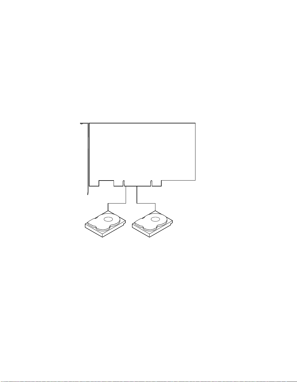
2.3.5 Disk Striping
Disk striping writes data across multiple disk drives instead of just one
disk drive, as shown in Figure 2.1.
2-4 I ntroduction to RAID
Copyright © 2002 by LSI Logic Corporation. All rights reserved.
Page 29

Figure 2.1 Disk Striping
MegaRAID Controller
Disk striping involves partitioning each disk d rive’s storage space into
stripes that can vary in size from 2 to 128 Kbytes. These stripes are
interleaved in a repeated, sequ ential manner. The combined storage
space is composed of s tripes from each dr ive. MegaRAID SCSI 320-1
suppor ts stripe sizes of 2, 4, 8, 1 6, 32, 64, or 128 Kbytes.
For example, in a four-disk system using on ly disk striping (as in RAID
level 0), segment 1 is written to d isk 1, segment 2 is wri tten to disk 2,
and so on. Disk stripi ng enhances p erformance be cause multip le dri ves
are accessed simultane ously; but disk striping does not provide data
redundancy.
2.3.5.1 Stripe Width
Stripe width i s a measure of the number of disks involved in an array
where striping is implemented. For example, a four-disk array with disk
striping has a st ripe width of four.
Segment 1
Segment 5
Segment 9
Segment 2
Segment 6
Segment 10
Segment 3
Segment 7
Segment 11
Segment 4
Segment 8
Segment 12
RAID Overvi ew 2-5
Copyright © 2002 by LSI Logic Corporation. All rights reserved.
Page 30
2.3.5.2 Stripe Size
The stripe s ize is the length of the interl eaved data segments that
MegaRAID SCSI 320-1 wr ites across multipl e drives. MegaRAID SCSI
320-1 suppor ts stripe sizes o f 2, 4, 8, 16, 32, 64, or 128 K bytes.
2.3.6 Disk Mirroring
With disk mirroring (used in RAID 1), data wr itten to one disk dr ive is
simultaneously wr itten to another disk dr ive, as shown in Figure 2.2.
Figure 2.2 Disk Mirroring
MegaRAID Controller
Segment 1
Segment 2
Segment 3
Segment 4 Segment 4 Duplicated
If one disk drive fails, the contents of the other disk dr ive can be used to
run the system and reconstr uct the failed drive. The primary advantage
of disk mirroring i s that it provides 100% data r edundancy. Since the
contents of the disk d rive are completely wr itten to a second dri ve, it
does not matter if o ne of the drives fails. Both drives contain th e same
data at all times. Either drive can act as the operationa l drive.
Although disk mirror ing provides 100% redund ancy, it is expensive
because each dr ive in the system must be duplic ated.
2-6 I ntroduction to RAID
Copyright © 2002 by LSI Logic Corporation. All rights reserved.
Segment 1 Duplicated
Segment 2 Duplicated
Segment 3 Duplicated
Page 31

2.3.7 Disk Spanning
Disk spanning allows multiple disk drives to function like one bi g drive.
Spanning overcomes lack of disk s pace and simplifies storag e
management by combinin g existing resources or adding rel atively
inexpensive resources. For example, four 60 Gbyte disk drives can be
combined to appear to t he operating system as one single 240 Gbyte
drive.
Disk spanning alone does not provide reliability or performance
enhancements. Spanned logical drives must have the same stripe s ize
and must be contiguous. In Figure 2.3, two RAID 1 arrays are turned into
a RAID 10 array.
Figure 2.3 Disk Spanning
MegaRAID Controller
Data Flow
Segment 1
Segment 3
Segment 5
RAID 1
Disk 1 Disk 4Disk 3
Segment 1
Segment 3
Segment 5
Disk 2
Segment 2
Segment 4
Segment 6
RAID 0
RAID 1
Segment 2
Segment 2
Segment 4
Segment 4
Segment 6
Segment 6
RAID Overvi ew 2-7
Copyright © 2002 by LSI Logic Corporation. All rights reserved.
Page 32

Table 2.1 describes how disk sp ann in g is us ed for RAID 10 an d RA ID 50 .
Table 2.1 Spanning for RAID 10 and RAID 50
Level Description
10 Configure RAID 10 by spanning two contiguous RAID 1 logical drives.
The RAID 1 logical drives must have the same stripe size.
50 Configure RAID 50 by spanning two contiguous RAID 5 logical drives.
The RAID 5 logical drives must have the same stripe size.
2.3.8 Parity
Parity generates a set of redunda ncy data f rom two or more par ent data
sets. The redundancy data can be use d to reconstr uct one of the pa rent
data sets. Parity data does not f ully duplicate the pa rent data sets. In
RAID, this method is applied to entire dr ives (dedicated parity ) or to
stripes acros s all disk drives in an array (distributed parit y).
RAID 5 combines distributed parity with disk striping. If a single disk drive
fails, it can be rebuilt from the parity an d the data on the remaining
drives. Parity provides redundancy for one dr ive failure without
duplicating the c ontents of entire disk dr ives, but parity generation can
slow the write process.
2.3.9 Hot Spares
A hot spare is an extra, unused disk drive that is par t of the disk
subsystem. It is usually in standby mode, ready for service if a drive fails.
Hot spares permit you to replace failed drives without syste m shutdown
or user inter vention.
Note:
Spanning two conti guous RAID 0 logical d rives does not
produce a new RAID level or add fault tolerance. It does
increase the si ze of the logical volume and imp roves
performance by doubling the number of spindles.
MegaRAID SCSI 320-1 implements automatic and transparent rebuilds
using hot spare dr ives, providing a high degree of fault tolerance and
zero downtime. The MegaRAID SCSI 320-1 RAID Management software
allows you to specify physical drives as hot spares. When a hot spare is
needed, the MegaRAID SC SI 320 -1 controller assigns the hot s pa re that
2-8 I ntroduction to RAID
Copyright © 2002 by LSI Logic Corporation. All rights reserved.
Page 33

has a capacity cl osest to and at least as great as that of the failed dr ive
to take the place of the failed dr ive.
Note:
2.3.10 Hot Swapping
Hot swapping is the manual replaceme nt o f a defective physical disk u ni t
while the computer is still runn ing. When a new dri ve has been instal led,
you must issue a command to rebuild the drive.
2.3.11 Disk Rebuild
You rebuild a di sk drive by recreating the data tha t had been stored on
the drive before the drive failed. Rebuilding can be done only in arrays
with data redundanc y such as RAID level 1, 5, 10, and 50.
Standby (warm spare) r ebuild is employed in a mirrored (RAID 1)
system. If a disk dr ive fails, an identical drive is imm ediately available.
The primar y data source disk d rive is the original disk drive.
A hot spare can be us ed to rebuild disk drives in RAID 1, 5, 10 , or 50
systems. If a hot spare is not available, the failed disk drive must be
replaced with a new disk drive so that the data on the failed drive can be
rebuilt.
Hot spares are employed only in arrays with redundanc y—
for example, RAID levels 1, 5, 10, and 50. A hot spare
connected to a speci fic MegaRAID SCSI 320- 1 controller
can be used only to r ebuild a d rive that i s co nnecte d to the
same controller.
The MegaRAID SCSI 3 20-1 controller automatic ally and transparently
rebuilds failed drives with user-def inable rebuild rates. If a hot spare is
available, the rebuild starts automatically when a drive fails. MegaRAID
SCSI 320-1 automati cally restar ts the system and the r ebuild if the
system goes down during a rebuild.
2.3.11.1 Rebuild Rate
The rebuild rate is the fraction of the compute cycle s dedicated to
rebuilding failed drives. A rebuild rate of 100% mea ns the system is
totally dedicated to r ebuilding the failed drive.
RAID Overvi ew 2-9
Copyright © 2002 by LSI Logic Corporation. All rights reserved.
Page 34

The MegaRAID SCSI 32 0-1 rebuild rate can be configured between 0%
and 100%. At 0%, the rebuild is only done if the system is not doing
anything else. At 100%, the rebuild has a higher pr iority than any other
system activity.
2.3.12 Logical Drive States
Table 2.2 describes the l ogical drive states.
Table 2.2 Logical Drive Sta tes
State Description
Optimal The drive operating condition is good. All configured drives are
Degraded The drive ope rating condit ion is not optimal. On e of the
Failed The drive has failed.
Offline The drive is not available to MegaRAID SCSI 320-1.
2.3.13 SCSI Drive States
A SCSI disk dri ve can be in one of the states described in Table 2.3.
Table 2.3 SC SI Drive States
State Description
Online
(ONLIN)
Ready
(READY)
Hot Spare
(HOTSP)
Fail
(FAIL)
online.
configured drives has failed or is offline.
The drive is functioning normally and is a part of a configured
logical drive.
The drive is functioning normally but is not part of a configured
logical drive and is not designated as a hot spare.
The drive is powered up and ready for use as a spare in case an
online drive fails.
A fault has occurred in the drive, placing it out of service.
Rebuild
(REB)
2-10 Introduction to RAID
Copyright © 2002 by LSI Logic Corporation. All rights reserved.
The drive is being rebuilt with data from a failed drive.
Page 35

2.3.14 Disk Array Types
Table 2.4 describes the RAID dis k array types.
Table 2.4 Disk Array Types
Type Description
SoftwareBased
SCSI to SCSI The array controller resides outside of the host computer and
Bus-Based The array controller resides on the bus (for example, a PCI or
The array is managed by software running in a host computer
using the host CPU bandwidth. The disadvantages associated
with this method are the load on the host CPU and the need
for different software for each operating system.
communicates with the host through a SCSI adapter in the
host. The array management software runs in the controller. It
is transparent to the host and independent of the host
operating system. The disadvantage is the limited data transfer
rate of the SCSI channel between the SCSI adapter and the
array controller.
EISA bus) in the host comput er and has it s own CPU to
generate the parity and handle other RAID functions. A busbased controller can transfer data at the speed of the host bus
(PCI, ISA, EISA, VL-Bus) but is limited to the bus it is designed
for. MegaRAID SCSI 320-1 resides on a PCI bus, which can
handle data transfer at up to 132 Mbytes/s. With MegaRAID
SCSI 320-1, the channel can handle data transfer rates up to
320 Mbytes/s per SCSI channel.
2.3.15 Enclosure Management
Enclosure managem ent is the intelligent m onitoring of the disk
subsystem by software and/or hardware.
The disk subsystem can be part of the host computer or can be separate
from it. Enclosure managem ent helps you stay informed of events in the
disk subsystem, such as a drive or power supply failure. Enclosure
management increa ses the fault tolerance of the disk subsystem.
RAID Overvi ew 2-11
Copyright © 2002 by LSI Logic Corporation. All rights reserved.
Page 36

2-12 Introduction to RAID
Copyright © 2002 by LSI Logic Corporation. All rights reserved.
Page 37

Chapter 3
RAID Levels
This chapter descr ibes each suppor ted RAID level and the factors to
consider when choosi ng a RAID level. It contains the following sections:
· Section 3.1, “Selec ting a RAID Level”
· Section 3.2, “RAID 0”
· Section 3.3, “RAID 1”
· Section 3.4, “RAID 5”
· Section 3.5, “RAID 10”
· Section 3.6, “RAID 50”
3.1 Selecting a RAID Level
To en sure the best performanc e, you should select the optimal RAID
level when you create a system drive. The optimal RA ID level for your
disk array depends on a number of factors:
· The number of drives in the disk array
· The capacity of the dr ives in the array
· The need for data redundancy
· The disk performance requirements
Note:
MegaRAID SCSI 320-1 Hardware Guide 3-1
Copyright © 2002 by LSI Logic Corporation. All rights reserved.
The SCSI 320-1 control ler suppor ts a maximum of 15
physical drives.
Page 38

3.2 RAID 0
RAID 0 provides disk str iping across all dr ives in the RAID subsystem.
RAID 0 does not provide any da ta redundancy, but does offer the best
performance of any RAID level. RAID 0 breaks up data into sm aller
blocks and then writes a block to each drive in the array . The size of each
block is determined by the stri pe size parameter, set during the cr eation
of the RAID set. RAID 0 of fers high bandwidth. By breaking up a l arge
file into smaller blocks, MegaRAID SCS I 320-1 ca n use s everal drives to
read or write the file faster. RAID 0 involves no parity cal culations to
complicate the wri te operation. This makes RAID 0 ideal for application s
that require high ban dwidth but do not require fault tolerance.
Uses RAID 0 provides high data throughput, especially for large
Strong Points Provides increased data throughput for large files. No
Weak Po in ts Does not provide fault tolerance. All data lost if any drive
Drives 1 to 15
files. Suitable for any environment that does not require
fault tolerance.
capacity loss penalty for parity.
fails.
The initiator takes one ID per channel. This leaves 15 IDs
available for one channel.
Figure 3.1 shows a RAID 0 array with four disk drives.
3-2 R AID Levels
Copyright © 2002 by LSI Logic Corporation. All rights reserved.
Page 39

Figure 3.1 RAID 0 Array
MegaRAID Controller
3.3 RAID 1
Segment 1
Segment 5
Segment 9
Segment 2
Segment 6
Segment 10
Segment 3
Segment 7
Segment 11
Segment 4
Segment 8
Segment 12
In RAID 1, the MegaRAID S CSI 320 -1 dup licates all d ata fro m one dr ive
to a second drive. RAID 1 provides complete dat a redundancy, but at the
cost of doubling the req uired data storage capaci ty.
Uses Use RAID 1 for small databases or any other environment
Strong Points Provides complete data redundancy. RAID 1 is ideal for any
Weak Po in ts Requires twice as many disk drives. Performance is im paired
Drives 2
that requi res fault tole rance but small capacity.
application that requires fault tolerance and minimal capacity.
during drive rebuilds.
Figure 3.2 shows a RAID 1 array.
RAID 1 3-3
Copyright © 2002 by LSI Logic Corporation. All rights reserved.
Page 40

Figure 3.2 RAID 1 Array
MegaRAID Controller
3.4 RAID 5
Segment 1
Segment 2
Segment 3
Segment 4 Segment 4 Duplicated
Segment 1 Duplicated
Segment 2 Duplicated
Segment 3 Duplicated
RAID 5 includes disk str iping at t he byte level and parity. In RAID 5, the
parity information i s written to several drives. RAID 5 is best su ited for
networks that perfor m many small I/O transac tions simultaneously.
RAID 5 addresses the bottlen eck issue for random I/O operation s. Since
each drive contains both data and parity, numerous writes can take place
concurrently. In addition, robust caching algorithms a nd hardware ba sed
3-4 R AID Levels
Copyright © 2002 by LSI Logic Corporation. All rights reserved.
Page 41

exclusive-or assist make RAID 5 perform ance exceptional in many
different environments.
Uses Provides high data throughput, esp ecial ly f o r large files . Us e
Strong Points Provides data redundancy and good performance in most
Weak Po in ts Disk drive performance is reduced if a drive is being rebuilt.
Drives 3 to 15
Figure 3.3 shows a RAID 5 array with six disk drives.
Figure 3.3 RAID 5 Array
RAID 5 for transaction processing applications, because
each drive can read and write independently. If a drive fails,
the MegaRAID SCSI 320-1 uses the parity drive to recreate
all missing information. Use also for office automation and
online customer service that requires fault tolerance. Use
for any application that has high read request rates but low
write request rates.
environments
Environments with few processes do not perform as well
because the RAID overhead is not offset by the
performance gains in handling simultaneous processes.
MegaRAID Controller
Note: Parity is distributed
across drives in the array.
Disk 1 Disk 2 Disk 3 Disk 4 Disk 5 Dis k 6
Segment 1
Segment 7
Parity (9–12)
Segment 2
Segment 8
Data Flow
Segment 3
Segment 9
Parity (5–8)
Segment 4
Segment 10
Segment 5
Segment 11
Parity (1–4)
Segment 6
Segment 12
RAID 5 3-5
Copyright © 2002 by LSI Logic Corporation. All rights reserved.
Page 42

3.5 RAID 10
RAID 10 is a combin ation of RA ID 0 and RAID 1. RAI D 10 ha s mirrored
drives. RAID 10 breaks up da ta into sm aller blocks, and then s tripes the
blocks of data to each RAID 1 RAID set. Eac h RAID 1 RAID set then
duplicates its data to its other drive. The size of each block is determined
by the stripe size parameter, which is set during the creation of th e RA ID
set. RAID 10 can sustain one to four drive failures while maintaining data
integrity, if each failed disk is i n a different RAID 1 array.
Uses Works best for data storage that must have 100%
Strong Points Provides both high data transfer rates and complete data
Weak Po in ts Requires twice as many drives as all other RAID levels
Drives 4 to 16
redundancy of mirrored arrays and that also needs the
enhanced I/O performance of RAID 0 (striped arr ays). RAID
10 works well for medium-sized databases or any
environment that requires a higher degree of fault tolerance
and moderate to medium capacity.
redundancy.
except RAID 1.
Figure 3.4 shows a RAID 10 array with four disk dr ives.
3-6 R AID Levels
Copyright © 2002 by LSI Logic Corporation. All rights reserved.
Page 43

Figure 3.4 RAID 1 0 Array
MegaRAID Controller
Data Flow
3.6 RAID 50
Segment 1
Segment 3
Segment 5
RAID 1
Disk 1 Disk 4Disk 3
Segment 1
Segment 3
Segment 5
Disk 2
Segment 2
Segment 4
Segment 6
RAID 0
RAID 1
Segment 2
Segment 2
Segment 4
Segment 4
Segment 6
Segment 6
RAID 50 provides the features of both RAID 0 and RAID 5, including both
parity and disk striping across mul tiple drives. RAID 50 is bes t
implemented on two RAID 5 disk arrays with data striped across both
disk arrays. RAID 50 breaks up data into smaller blocks, and then stripes
the blocks of data to each RAID 5 RAI D set. RAID 5 bre aks up data into
smaller blocks, calculates par ity by performing an exclusive-or on the
blocks, and then writes the blocks of data and pa rity to each dr ive in the
array. The s ize of each block is deter mined by the str ipe size parameter,
which is set during the creation of the RAID set.
RAID 50 3-7
Copyright © 2002 by LSI Logic Corporation. All rights reserved.
Page 44

RAID 50 can sustai n one to four drive failures while maintaini ng data
integrity, if each failed disk is i n a different RAID 5 array.
Uses Works best when used with data that requires high
Strong Points Provides high data throughput, data redundancy, and very
Weak Po in ts Requires 2 to 4 times as many parity drives as RAID 5.
Drives 6 to 15
Figure 3.5 shows a RAID 50 array with si x disk drives.
Figure 3.5 RAID 5 0 Array
reliability, high request rates, high data transfer, and
medium to large capacity.
good performance.
The initiator takes one ID per channel. This leaves 15 IDs
available for one channel.
MegaRAID Controller
RAID 5
Disk 1 Disk 2 Disk 3
Segment 1
Segment 6
Parity (9-10)
Segment 2
Parity (5-6)
Segment 9
3-8 R AID Levels
Copyright © 2002 by LSI Logic Corporation. All rights reserved.
Parity (1-2)
Segment 5
Segment 10
Data Flow
RAID 0
Disk 4 Disk 5 Disk 6
Segment 3
Segment 8
Parity (11-12)
RAID 5
Segment 4
Parity (7-8)
Segment 11
Parity (3-4)
Segment 7
Segment 12
Page 45

Chapter 4
Features
This chapter explains the features of the Me gaRAID SCSI 320-1. It
contains the following sections :
· Section 4.1, “SMART Technology”
· Section 4.2, “Confi guration on Disk”
· Section 4.3, “Confi guration Features”
· Section 4.4, “Array Performance Features”
· Section 4.5, “RAID Management Features”
· Section 4.6, “Fault Tolerance Features”
· Section 4.7, “Soft ware Utilities”
· Section 4.8, “Operating System Software Drivers”
· Section 4.9, “Mega RAID SCSI 320-1 Speci fications”
· Section 4.10, “RAI D Management”
· Section 4.11, “Com patibility”
MegaRAID is a family of high perform ance intelligent PCI-to-SCSI h ost
adapters with RAID co ntrol c apabiliti es. The Me gaRAID S CSI 32 0-1 h as
a SCSI channel that su pports Ultra320 an d Wide SCSI at data transfer
rates up to 320 Mbytes/s. The SCSI c hannel suppor ts up to 15 Wide
devices and up to seven non-Wide devices.
4.1 SMART Technology
The MegaRAID SCSI 3 20-1 Self Monitorin g Analysis and Repor ting
Tec hnology (SMART) detects up to 70% of all predictable dr ive failures.
SMART monitors the internal performance of all motors, heads, and drive
electronics.
MegaRAID SCSI 320-1 Hardware Guide 4-1
Copyright © 2002 by LSI Logic Corporation. All rights reserved.
Page 46

4.2 Configur ation on Disk
Configuration on Disk (d rive roaming) saves configuration informatio n
both in nonvolatile random access memor y ( NVRAM) o n the Mega RAID
SCSI 320-1, and on the di sk drives controlled by the MegaR AID SCSI
320-1. If the MegaRAID SCSI 320-1 is replaced, the new Mega RAID
SCSI 320-1 controller can detect the actual RAID configuration,
maintaining the integrity of the data on each drive, even if the drives have
changed channel an d/or target ID.
4.3 Configur ation Features
Table 4.1 contains the configuration features for the MegaRAID 320-1.
Table 4.1 Configuration Features
Specification Feature
RAID levels 0, 1, 5, 10, and 50
SCSI channels 1
Maximum number of drives per channel 15
Array interface to host PCI 2.2
Drive interface Fast and Wide, Ultra320 single-
Upgradeable cache size Cache memory onboard
Cache function Write-through, write-back, adaptive
Multiple logical drives/arrays per
controller
Maximum number o f MegaRAID SCSI
320-1 controllers per system
Online capacity expansion Yes
Hot spare support Yes
ended and low-voltage differential
(LVD)
read-ahead, no read-ahead, readahead
Up to 40 logical drives per controller
12
4-2 Features
Copyright © 2002 by LSI Logic Corporation. All rights reserved.
Page 47

Table 4.1 Configuration Features (Cont.)
Specification Feature
Flashable fi rmware Yes
Hot swap devices supported Yes
Non-disk devices sup porte d Yes
Mixed capacity hard disk drives Yes
Number of 16-bit internal connectors 1
Number of 16-bit external connectors 1
Suppor t for hard di sk drives with
capacities of more than 8 Gbytes.
Clustering support (Failover control) No
Online RAID level migration Yes
RAID remapp ing Yes
No reboot necessary after expansion Yes
More than 20 0 Qtags per physic al drive Yes
Hardware clustering support on the
board
User-speci fied rebuild rate Yes
4.4 Array Performance Features
Table 4.2 lists the array performance features.
Table 4.2 Array Performance Features
Specification Feature
Yes
Yes
Host data transfer rate 533 Mbytes/s
Drive data transfer rate 320 Mbytes/s
Stripe sizes 2, 4, 8, 16, 32, 64, or 128 Kbytes
Array Performance Features 4-3
Copyright © 2002 by LSI Logic Corporation. All rights reserved.
Page 48

4.5 RAID Management Features
Table 4.3 lists the RAID management features.
Table 4.3 RAID Management Features
Specification Feature
Support for SNMP Yes
Performance Monito r provided Yes
Remote control and monitoring Yes
Event broadcast and event alert Yes
Hardware connector RS232C
Drive roamin g Yes
Support for concurrent multiple stripe sizes Yes
Windows NT, 2000, XP, and .NET server support using a GUI
client utility
4.6 Fault Tolerance Features
Table 4.4 lists the fault tolerance features.
Table 4.4 Fault Tolerance Features
Specification Feature
Support for SMART Yes
Enclosure management SCSI-accessed fault-tolerant
Drive failure detection Automatic
Drive rebuild using hot spares Automatic
Parity generation for RAID Hardware
Yes
enclosure (SAF-TE) compliant
4-4 Features
Copyright © 2002 by LSI Logic Corporation. All rights reserved.
Page 49

4.7 Software Utilities
Table 4.5 lists the software utilit y features.
Table 4.5 Software Utilit ies
Specification Feature
Graphical user interface Yes
Management utility Yes
Bootup configuration using MegaRAID Manager Yes
Online read, write, and cache policy switching Yes
4.8 Operating System Software Drivers
MegaRAID SCSI 320-1 includes a DOS software configuration utility, and
drivers for:
· Windows NT 4.0
· Windows 2000
· Windows .NET
· Windows XP
· Novell NetWare 5.1, 6.0
· Red Hat Linux 7.2, 7.3
· DOS version 6.xx or later
The DOS drivers for MegaRAID are co ntained in the firm ware on the
MegaRAID controller, except for the DOS ASPI and CD drivers. Call your
LSI OEM suppor t representative or acce ss the web site at
www.lsilogic.com
systems.
for information about drivers for other operatin g
Software Utilities 4-5
Copyright © 2002 by LSI Logic Corporation. All rights reserved.
Page 50

4.9 MegaRAID SCSI 320-1 Specifications
Table 4.6 lists the specifications for the SCSI 320-1.
Table 4.6 MegaRAID SCSI 320-1 Specifications
Parameter Specification
Card size Low profile PCI Adapter card size (6.875" X 2.5")
Processor Intel GC80302 64-bit RISC processor at 100 MHz
Bus type PCI 2.2
SCSI controller LSI Logic 53C1020
PCI controller Intel GC80302
Bus data transfer rate Up to 532 Mbytes/s
BIOS MegaRAID BIOS
Cache configuration Predefined during manufacturing; ECC through a
66 MHz 72-bit unbuffered 3.3 V SDRAM
Firmware 1 MB × 8 flash ROM
Non-volatil e random
access memory
(NVRAM)
Operating voltage 5.00 V ± 0.25 V
SCSI controller One SCSI controller for Ultra320 and Wide support
SCSI data transfer rate Up to 320 Mbytes/s
SCSI bus LVD or single-ended
SCSI termination Active, single-ended or LVD
Termination disable Automatic through cable and device detection
Devices per SCSI
channel
SCSI device types
supported
RAID levels supported 0, 1, 5, 10, and 50
32 KB × 8 for storing RAID configuration
Up to 15 Wide or 7 non-Wide SCSI devices. Up to 6
non-disk SCSI drives per MegaRAID SCSI 320-1
controller.
Synchronous or asynchronous. Disk and non-disk.
4-6 Features
Copyright © 2002 by LSI Logic Corporation. All rights reserved.
Page 51

Table 4.6 MegaRAID SCSI 320-1 Specifications (Cont.)
Parameter Specification
SCSI connectors One 68-pin internal high-density connector for 16-bit
Serial port 3-pin RS232C-compatible berg
4.9.1 PCI Bridge/ CPU
MegaRAID SCSI 320-1 us es the Intel GC80302 PCI bridge with an
embedded 80960JT RIS C processor r unning at 66 MHz. The GC80302
bridge handles d ata transfers between the primar y (host) PCI bus, the
secondar y PCI bus, cache memory, and the SCSI bus. The DMA
controller suppor ts chaining and unaligned data transfers. The
embedded 80960JT CPU directs all controller functions, including
command processi ng, SCSI bus transfers, RAID processing, dr ive
rebuilding, cache managemen t, and error recovery.
4.9.2 Cache Memory
MegaRAID SCSI 320-1 cache memory r esides in an onboard m emory
bank that uses 2 M x 72 (16 Mbyte), 4 M x 72 (32 Mbyte), 8 M x 72 (6 4
Mbyte) or 16 M x 72 (128 M byte) unbuffered 3.3 V SDRAM. Possible
configurations are 8, 16, 3 2, 64, or 128 Mbytes. The maximum
achievable memory bandwidth is 528 Mbytes/s.
SCSI devices. One very-hig h density 6 8-pin extern al
connector for Ultra and Wide SCSI.
MegaRAID suppor ts write-through o r write-back caching, whic h can be
selected for each logical drive. To improve performance in sequential disk
accesses, MegaRAID does not use read-ahead cachi ng for the current
logical drive. The default setting for the read policy is Normal, meaning
no read-ahead cachi ng. You can disable read-ahead caching.
Warning:
4.9.3 MegaRAID BIOS
The BIOS resides on a 1 MB × 8 flash ROM for easy upgrade. The
MegaRAID BIOS suppor ts INT 13h calls to boo t DOS without special
MegaRAID SCSI 320-1 Specifications 4-7
Copyright © 2002 by LSI Logic Corporation. All rights reserved.
Write caching is not recommended for the physical drives.
When write cac he is ena bled, loss of data can oc cur when
power is interrupted.
Page 52

software or device drivers. The MegaR AID BIOS provides an extensive
setup utility that c an be accessed by pressing <Ctrl><M> at B IOS
initialization. The Me gaRAID BIOS Configurati on Utility is descri bed in
the MegaRAID Configurati on Software Guide.
4.9.4 Serial Port
MegaRAID SCSI 320-1 includes a 3-pin RS232C-compatible seri al port
berg connector, which can conne ct to communications devices.
4.9.5 SCSI Bus
MegaRAID SCSI 320-1 has a Fast and Wide Ultra320 SCSI channel that
suppor ts both LVD and single-ended devices with ac tive termination.
Synchronous and asy nchronous devices are suppor ted. MegaRAID
SCSI 320-1 provides automa tic termination d isable using cable
detection. The SCSI channe l supports up to 15 Wide or seven non-Wide
SCSI devices at speeds u p to 320 Mbytes/s. MegaRAID SCS I 320-1
suppor ts up to
six non-dis k devices per controller.
4.9.6 SCSI Connectors
The MegaRAID SCSI 3 20-1 has two types of SCS I connectors:
· 68-pin high density internal connec tor
· 68-pin very-high-de nsity external connector
Both connector types c an be used for the SCSI channel.
4.9.7 SCSI Termination
The MegaRAID SCSI 3 20-1 uses active termina tion on the SCSI bus,
conforming to Alter native 2 of the SCSI-2 specif ications. Termination
enable/disable is automatic thr ough cable detection.
4-8 Features
Copyright © 2002 by LSI Logic Corporation. All rights reserved.
Page 53

4.9.8 SCSI Firmw are
The MegaRAID SCSI 3 20-1 firmware handle s all RAID and SCSI
command processi ng and also suppor ts the features listed in Table 4.7.
Table 4.7 SC SI Firmware
Feature Description
Disconnect/
reconnect
Tagged command
queuing
Scatter/gather Multiple address/count pairs
Multi-threading Up to 255 simultaneous commands with elevator sorting
Stripe si ze Variable for all lo gical dr ives: 2, 4, 8, 1 6, 32, 64, o r
Rebuild Multiple rebuilds and consistency checks, with user-
4.10 RAID Management
RAID management is p rovided by software utilities that manage and
configure the RAID syst em and MegaRAID SCSI 320- 1, create and
manage multiple disk arrays, control and mon itor multiple RAID se rvers,
provide error statisti cs logging, and provide on line maintenance. They
include:
Optimizes SCSI bus seek
Multiple tags to improve random access
and concatenation of requests per SCSI channel
128 Kbytes
definable priority
· MegaRAID BIOS Configuratio n Utility
· WebBIOS Configuration Utility
· Power Console Plus
· MegaRAID Manager
4.10.1 MegaRAID BIOS Configuration Utility
The BIOS Configuration Uti lity (<Ctrl><M>) is use d to configure and
maintain RAID arrays, format hard drives, and manage the RAID system.
RAID Management 4-9
Copyright © 2002 by LSI Logic Corporation. All rights reserved.
Page 54

It is independent of any ope rating system. See the MegaRAID
Configuration Software Guide for additional information.
4.10.2 WebBIOS Configuration Utility
The WebBIOS Configuration Utility is an HTML-based utility used to
configure and maintain RAID arrays, format hard drives, and manage the
RAID system. See the Me gaRAID Configuration Software Guide for
additional informa tion.
4.10.3 Power Console Plus
Power Console Plus runs in Windows NT, 2000, XP, and .NET. It
configures, monitors, and mai ntains multiple RAID ser vers from any
network node or a remo te location. See the MegaRA ID Configuration
Software Guide for additional informati on.
4.10.4 MegaRAID Manager
This is a character-based ut ility that wor ks in DOS, Novell NetWare, and
Red Hat Linux. See the MegaRA ID Configuration Software Guide for
additional informa tion.
4.11 Compatibility
MegaRAID SCSI 320-1 compatibility issues include:
· Server management
· SCSI device compa tibility
· Software compatibility
4.11.1 Server Management
As a simple networ k management protocol (SNM P) agent, MegaRAID
SCSI 320-1 suppor ts all SNMP manager s.
4.11.2 SCSI Device Compatibility
MegaRAID SCSI 320-1 suppo r ts SCSI hard dr ives, CD drives, and tape
drives.
4-10 Features
Copyright © 2002 by LSI Logic Corporation. All rights reserved.
Page 55

4.11.3 Software
All SCSI backup and utility software should work with MegaRAID SCSI
320-1. This software is not provid ed with MegaRAID SCSI 320-1 .
Compatibility 4-11
Copyright © 2002 by LSI Logic Corporation. All rights reserved.
Page 56

4-12 Features
Copyright © 2002 by LSI Logic Corporation. All rights reserved.
Page 57

Chapter 5
Configuring Physical Drives,
Arrays, and Logical Drives
This chapter explains how to configure SCS I physical dr ives, arrays, and
logical drives connected to the MegaRAID SCSI 320- 1 controller. It
contains the following sections :
· Section 5.1, “Confi guring SCSI Physical Dr ives”
· Section 5.2, “Confi guring Arrays”
· Section 5.3, “Cre ating Logical Drives”
· Section 5.4, “Confi guring Logical Dr ives”
· Section 5.5, “Pla nning the Array Configuration”
5.1 Confi guring SCSI Physical Drives
SCSI physical drives must be organ ized into logical drives. The arrays
and logical dri ves that you construct must be able to suppor t the RAID
level that you select. The MegaRAID SCSI 320 -1 controller has one
SCSI channel.
5.1.1 Basic Configuration Rules
You should observe the following guideli nes when connecting and
configuring SCS I devices in a RAID array:
· You can pla ce up to 15 physical dr ives in an a rray, depending on the
RAID level.
· Include all drives that h ave the same capacity in the same array.
· Make sure any hot spare has a ca pacity that is at leas t as large as
the largest dri ve that may be replaced by the hot spare.
· When replacing a failed drive, make sure that the re placement dr ive
has a capacity that i s at least as large as the d rive being replaced.
MegaRAID SCSI 320-1 Hardware Guide 5-1
Copyright © 2002 by LSI Logic Corporation. All rights reserved.
Page 58

Note: Be su re to back up your data regular ly, even when using
RAID.
5.1.2 Current Physical Device Configuration
Use Table 5.1 to record the current configuration for your physical
devices.
Table 5.1 Physical Device Configuration - SCSI Channel 1
SCSI ID Device Description Termination?
0
1
2
3
4
5
10
11
12
13
14
15
6
8
9
5-2 Configuring Physical Drives, Arrays, and Logical Drives
Copyright © 2002 by LSI Logic Corporation. All rights reserved.
Page 59

5.1.3 Logical Drive Configuration
Use Table 5.2 to record the configu ration for your logical drives.
Table 5.2 Logical Drive Configuration
Logical
Drive
LD0
LD1
LD2
LD3
LD4
LD5
LD6
LD7
LD8
LD9
LD10
LD11
LD12
LD13
RAID
Level
Stripe
Size
Logical Drive
Size
Cache
Policy
Read
Policy
Write
Policy
# of Physical
Drives
LD14
LD15
LD16
LD17
LD18
LD19
LD20
LD21
Configuring SCSI Physical Drives 5-3
Copyright © 2002 by LSI Logic Corporation. All rights reserved.
Page 60

Table 5.2 Logical Drive Configuration (Cont.)
Logical
Drive
LD22
LD23
LD24
LD25
LD26
LD27
LD28
LD29
LD30
LD31
LD32
LD33
LD34
LD35
RAID
Level
Stripe
Size
Logical Drive
Size
Cache
Policy
Read
Policy
Write
Policy
# of Physical
Drives
LD36
LD37
LD38
LD39
5-4 Configuring Physical Drives, Arrays, and Logical Drives
Copyright © 2002 by LSI Logic Corporation. All rights reserved.
Page 61

5.1.4 Physical Device Layout
Use Table 5.3 to record the physical device layout.
Table 5.3 Physical Device Layout
Target ID
Device type
Logical drive number/Drive number
Manufacturer/M odel number
Firmware level
Target ID
Device type
Logical drive number/Drive number
Manufacturer/M odel number
Channel 1
Firmware level
Target ID
Device type
Logical drive number/Drive number
Manufacturer/M odel number
Firmware level
Target ID
Device type
Logical drive number/Drive number
Manufacturer/M odel number
Firmware level
Target ID
Device type
Logical drive number/Drive number
Configuring SCSI Physical Drives 5-5
Copyright © 2002 by LSI Logic Corporation. All rights reserved.
Page 62

Table 5.3 Physical Device Layout (Cont.)
Channel 1
Manufacturer/M odel number
Firmware level
Target ID
Device type
Logical drive number/Drive number
Manufacturer/M odel number
Firmware level
Target ID
Device type
Logical drive number/Drive number
Manufacturer/M odel number
Firmware level
Target ID
Device type
Logical drive number/Drive number
Manufacturer/M odel number
Firmware level
Target ID
Device type
Logical drive number/Drive number
Manufacturer/M odel number
Firmware level
Target ID
Device type
Logical drive number/Drive number
5-6 Configuring Physical Drives, Arrays, and Logical Drives
Copyright © 2002 by LSI Logic Corporation. All rights reserved.
Page 63

Table 5.3 Physical Device Layout (Cont.)
Channel 1
Manufacturer/M odel number
Firmware level
Target ID
Device type
Logical drive number/Drive number
Manufacturer/M odel number
Firmware level
Target ID
Device type
Logical drive number/Drive number
Manufacturer/M odel number
Firmware level
Target ID
Device type
Logical drive number/Drive number
Manufacturer/M odel number
Firmware level
Target ID
Device type
Logical drive number/Drive number
Manufacturer/M odel number
Firmware level
Configuring SCSI Physical Drives 5-7
Copyright © 2002 by LSI Logic Corporation. All rights reserved.
Page 64

Table 5.3 Physical Device Layout (Cont.)
Target ID
Device type
Logical drive number/Drive number
Manufacturer/M odel number
Firmware level
5.2 Configur ing Arrays
You organize the physical dis k drives in arrays after they are connected
to the MegaRAID SCSI 32 0-1, and after they are formatted an d
initialized. An array can consist o f up to 15 physical disk dr ives,
depending on the RAID level.
Channel 1
The MegaRAID SCSI 320-1 su ppor ts up to eight arrays. The number of
drives in an array determine s the RAID levels that can be suppor ted.
5.2.1 Arranging Arrays
You must arran ge the arrays to provide additional organ ization for the
drive array. You must arrange arrays so that you can create system drives
that can function as boot devices.
You can se quentially arrange arrays with an id entical number of dri ves
so that the drives in th e group are spanned. Spanne d drives can be
treated as one large d rive. Data can b e str iped a cros s multiple arrays as
one logical dri ve.
You can cr eate spanned drives by using the Meg aRAID BIOS Setup
utility or the MegaRAID Ma nager.
5.2.2 Creating Hot Spares
Any drive that is present, formatted, an d initiali zed, but is not included in
a array or logical drive is automa tically designated as a hot spare.
5-8 Configuring Physical Drives, Arrays, and Logical Drives
Copyright © 2002 by LSI Logic Corporation. All rights reserved.
Page 65

You can also designate dr ives as hot spares using the Mega RAID BIOS
Configuration Utility, the MegaRAID Manager, or Power Console Plus.
5.3 Creating Logical Drives
Logical drives are arrays or spanned arrays that are presented to the
operating system. You must create one or m ore logical drives.
The logical dri ve capacity can i nclude all or any por tion of an array. The
logical drive capacity can also be larger than an array by using spanning.
The MegaRAID SCSI 3 20-1 supports up to 40 logical dr ives.
5.3.1 Configuration Strategies
The most impor tant factors in RAID array configuration ar e: drive
capacity, drive availability (fault tolerance), an d drive performance. You
cannot configure a l ogical drive that optim izes all three factors, but it is
easy to choose a lo gica l dr ive conf iguration t hat maximizes one factor a t
the expense of the other two factors, although n eeds are seldom that
simple.
5.3.1.1 Maximize Capacity
RAID 0 achieves maximum drive capacity, but does not provide data
redundancy. Maximum drive capacity for each RAID level is shown
below. OEM-level firmware tha t can span up to 4 logic al drives is
assumed. Table 5.4 descr ibes the RAID levels, including the number of
drives required, and the capacity.
Table 5.4 Capacity for RAID Levels
RAID
Level Description
0Striping
without parity
1 Mirroring 2 (Capacity of smallest disk) X (1)
5 Striping with
floating parity
drive
Creating L ogical Dri ves 5-9
Copyright © 2002 by LSI Logic Corporation. All rights reserved.
Drives
Required Capacity
1 – 15 (Number of disks) X capacity of
smallest disk
3 – 15 (Num ber of disks) X (capacity of
smallest disk) - (capacity of 1 disk)
Page 66

Table 5.4 Capacity for RAID Levels (Cont.)
RAID
Level Description
10 Mirroring and
Striping
50 RAID 5 and
Striping
Note: The M egaraid SCSI 320-1 contr oller suppor ts a maximum
of 15 physical drives.
5.3.1.2 Maximizing Drive Availability
You can max im ize the availability o f data on t he physical dis k dr ive in th e
logical array by maximizing t he level of fault tolerance. Table 5.5
describes the levels of fault tolerance for the RAID levels.
Table 5.5 Fault Tolerance for RAID Levels
RAID Level Fault Tolerance Protection
Drives
Required Capacity
4 – 14
(Must be a
multiple of 2.)
6 – 15 (Must
be a multiple
of the
number of
arrays.)
(Number of disks) X (cap acity of
smallest disk ) / (2)
(Number of disks) X (cap acity of
smallest dis k) – (c apac ity of 1 d isk X
number of Arrays)
0 No fault tolerance.
1 100% protection through data mirroring.
5 100% protection through striping and parity. The data is striped
and parity data is written across a number of physical disk
drives.
10 100% protection through data mirroring.
50 100% protection through data striping and parity. All data is
striped and parity data is written across all drives in two or
more arrays.
5.3.1.3 Maximizing Drive Performance
You can co nfigure an array for optimal performance. But optimal dr ive
configuration for one type of application will probably no t be optimal for
any other application. A basic guideline of t he performance
5-10 Configuring Physical Drives, Arrays, and Logical Drives
Copyright © 2002 by LSI Logic Corporation. All rights reserved.
Page 67

characteristic s for RAID drive arrays at each RAID level is shown in
Table 5.6.
Table 5.6 Performance Characteristics for RAID Levels
RAID Level Performance Characteristics
0 Excellent for all types of I/O activity, but provides no data
security.
1 Provides data redundancy and good performance.
5 Provides data redundancy and good performance in most
environments.
10 Provides data redundancy and excellent performance.
50 Provides data redundancy and very good performance.
5.3.2 Assigning RAID Levels
Only one RAID level can be assigned to ea ch logical drive. Table 5.7
shows the drives required per RAID level.
Table 5.7 Number of Physical Driv es for RAID Levels
RAID
Level Minimum # of Physical Drives Maximum # of Physical Drives
01 15
12 2
53 15
10 4 14
50 6 15
Note:
The Megaraid SCSI 320-1 controller suppor ts a maximum
of 15 physical drives.
Creating L ogical Dri ves 5-11
Copyright © 2002 by LSI Logic Corporation. All rights reserved.
Page 68

5.4 Configur ing Logical Drives
After you have installed the MegaRAID SCS I 320-1 controller in the
server and have attached all physical disk drives, perform the following
actions to prepare a RA ID array:
1. Optimize the MegaRAID SCSI 320- 1 controller options for your
system. See Chapte r 6 for additional information.
2. If necessary, perform a low-level format of the SCSI drives that will
be included in the ar ray and the drives to be used for hot spares.
3. Press <Ctrl><M> to r un the MegaRAID Manag er.
4. Customize the RAID array and define and config ure one or more
logical drives by selecti ng Easy Configuration or New Configuration.
5. Create and configure one or mor e system drives (logical drives) by
selecting the RAID level, cache policy, read policy, and write policy.
6. Save the configuration.
7. Initialize the system dr ives.
After initializati on, you can install the operatin g system.
5.4.1 Optimizing Data Storage
5.4.1.1 Data Access Requirements
Each type of data stored in the disk subs ystem has a different freque ncy
of read and writ e acti vity. If you know the data access requirements, you
can more successf ully determine a strategy for optimizing the disk
subsystem capaci ty, availability, and performance.
Servers that support Video on Dema nd typica lly read the da ta often, but
write data infrequ ently. Both the read and write operations tend to be
long. Data stored on a general-purpos e file server involves relatively
short rea d and write operation s with relatively small files.
5.4.1.2 Array Functions
You must fir st define the major pur pose of the disk ar ray. Will this disk
array increase the system storage ca pacity for general-purp ose file and
print servers? Doe s this disk array suppor t any software system that
5-12 Configuring Physical Drives, Arrays, and Logical Drives
Copyright © 2002 by LSI Logic Corporation. All rights reserved.
Page 69

must be available 24 hours per day? Will the informa tion stored in this
disk array contain large audi o or video files that must be available on
demand? Will this dis k array contain data from a n imaging s ystem? You
must identify the p urpo se of th e data to be sto red in the disk sub system
before you can confidently choose a RAID level and a RAID
configuration.
5.5 Planni ng the Array Configuration
Fill out Table 5.8 to help plan this array.
Table 5.8 Factors for Planning the Array Configuration
Question Answer
Number of physical disk drives in the array
Purpose of this array. Rank the following factors:
Maximize drive cap acity
Maximize the safety of the data (fault tolerance)
Maximize hard drive performance and throughput
Number of hot spares
Amount of cache memory installed on MegaRAID SCSI 320-1
Are all of the disk drives and the server protected by an
uninterruptible power supply?
5.5.1 Using the Array Configuration Planner
The following table lists the possi ble RAID levels, fault tolerance, and
effective capacity for all possible drive configuratio ns for an array
consisting of one to e ight drives. This table does not take into account
any hot spare (standby) drives. You should always have a hot spare drive
in case of drive failure. RAID 1 requires two drives, RAID 10 at least four,
and RAID 50 at least six.
Planning the Array Configuration 5-13
Copyright © 2002 by LSI Logic Corporation. All rights reserved.
Page 70

Use Table 5.9 to plan the array configuration.
Table 5.9 Array Configuration Planner
# of Drives
Possible
RAID Levels
Relative
Performance
Fault
Tolerance
1 None Excellent No 100%
1 RAID 0 Excellent No 100%
2 None Excellent No 100%
2 RAID 0 Excellent No 100%
2 RAID 1 Good Ye s 50%
3 None Excellent No 100%
3 RAID 0 Excellent No 100%
3 RAID 5 Good Ye s 67%
4 None Excellent No 100%
4 RAID 0 Excellent No 100%
4 RAID 5 Good Ye s 75%
4 RAID 10 Good Yes 50%
5 None Excellent No 100%
5 RAID 0 Excellent No 100%
Effective
Capacity
5 RAID 5 Good Ye s 80%
6 None Excellent No 100%
6 RAID 0 Excellent No 100%
6 RAID 5 Good Ye s 83%
6 RAID 10 Good Yes 50%
6 RAID 50 Good Yes 67%
7 None Excellent No 100%
7 RAID 0 Excellent No 100%
7 RAID 5 Good Ye s 86%
8 None Excellent No 100%
5-14 Configuring Physical Drives, Arrays, and Logical Drives
Copyright © 2002 by LSI Logic Corporation. All rights reserved.
Page 71

Table 5.9 Array Configuration Planner (Cont.)
# of Drives
Possible
RAID Levels
Relative
Performance
Fault
Tolerance
8 RAID 0 Excellent No 100%
8 RAID 5 Good Ye s 87%
8 RAID 10 Good Yes 50%
8 RAID 50 Good Yes 75%
Effective
Capacity
Planning the Array Configuration 5-15
Copyright © 2002 by LSI Logic Corporation. All rights reserved.
Page 72

5-16 Configuring Physical Drives, Arrays, and Logical Drives
Copyright © 2002 by LSI Logic Corporation. All rights reserved.
Page 73

Chapter 6
Hardware Installation
This chapter explains how to install the MegaRAID SCSI 320-1 controller.
It contains the following secti ons:
· Section 6.1, “Hardware Re quirements”
· Section 6.2, “Instal lation Steps”
· Section 6.3, “Summar y”
6.1 Hardware Requirements
You must have the following in order to install the MegaRAID SCSI 320-1
controller and creat e arrays:
· A host computer with the following:
– A motherboa rd with 5 V/3.3 V PCI expansion slots that has an
available expansion slot
– Suppor t for PCI version 2.2 or later
– Intel Pentium, Pentium Pro, or more powerful CPU
– Floppy drive, color monitor, VGA adapter card , mouse, and
keyboard
· The MegaRAID SCSI 3 20-1 Installation CD
· The necessar y int er nal and/or exter na l SCSI ca bles and te r min ators
(this depends on the num ber and type of SCSI devices to b e
attached)
· An Uninterruptible Power Supply (UPS) for the en tire system
· Ultra320, Ultra, Fast SCSI 2 or Wide SCSI har d disk drives
MegaRAID SCSI 320-1 Hardware Guide 6-1
Copyright © 2002 by LSI Logic Corporation. All rights reserved.
Page 74

6.2 Installation Steps
The MegaRAID SCSI 3 20-1 provides extensive customization option s. If
you need only basic MegaRA ID SCS I 320-1 features and your compu ter
does not use other adapter cards with resource settings that may conflict
with MegaRAID SCSI 32 0-1 settings, even custom installation can be
quick and easy.
Table 6.1 lists the hardware in stallation st eps. Each step is d escribed in
detail in the following pages.
Table 6.1 Hardware Installation Steps
Step Action Additional Information
1 Unpack the MegaRAID controller and
inspect for dama ge. Make sure all i tems
are in the package.
2 Turn the computer off and remove the
power cord, and remove the cover.
3 Check the jumper settings on the
MegaRAID SCSI 320-1 controller.
4 Set SCSI termination.
5 Install the MegaRAID SCSI 320-1 card.
6 Connect the SCSI cables to SCSI devices.
7 Set the target IDs for the SCSI devices.
8 Replace the computer cover and turn the
power on.
9 Run the MegaRAID BIOS Configuration
Utility.
10 Install software dr ivers for the desired
operating systems.
If damaged, call your LSI
Logic OEM support
representative.
See page 6-3 for the
MegaRAID SCSI 320-1
jumper settings.
Be sure the S CSI devices
are powered up before, or
at the same time as, the
host computer.
Optional.
6-2 Hardware Installation
Copyright © 2002 by LSI Logic Corporation. All rights reserved.
Page 75

6.2.1 Step 1: Unpack
Unpack and install the hardware i n a static-free environment. R emove
the MegaRAID SCSI 320-1 controller card from the anti-static bag and
inspect it for damage. If the c ard appears damaged, o r if any item lis ted
below is missing, conta ct LSI Logic or your MegaRAI D OEM suppor t
representative. The MegaRAID SCSI 320- 1 co ntrol ler is shi pp ed wit h the
following:
· The Driver and Documenta tion CD, which contains these items:
– The M egaRAID Configuration Soft ware Guide
– The M egaRAID Operating Sys tem Driver Installation Gu ide
– The M egaRAID SCSI 320-1 H ardware Guide
– The software l icense agreement
– The Mega RAID SCSI 320-1 config uration utilities for DOS
· The warranty registration car d
6.2.2 Step 2: Power Down
Tur n off the computer, remove the power cord, then remove the cover.
Make sure the computer is tur ned off and disconne cted from any
networks before installi ng the controller card.
6.2.3 Step 3: Check Jumper Se ttings
Make sure the jumper settin gs on the MegaRAID SCSI 32 0-1 card are
correct. The jumpers are set at the factory and you probably do not nee d
to change them. Table 6.2 lists th e jumpers (and a co nnector).
Table 6.2 Jumpers for the MegaRAID SCSI 320-1
Item Description Type
J2 Dirty cache LED 2-pin header
J3 Clear EPROM 2-pin header
J4 BIOS enable 2-pin header
J5 SCSI activity LED 2-pin connector
J6 Serial port 3-pin header
Installat ion Steps 6-3
Copyright © 2002 by LSI Logic Corporation. All rights reserved.
Page 76

Table 6.2 Jumpers for the MegaRAID SCSI 320-1
Item Description Type
J8 Battery backup unit ( BBU)
40-pin header
daughter card connector
J9 SCSI bus termination power 2-pin header
J10 SCSI bus termination enable
3-pin header
control
Figure 6.1 shows the location of th ese items on the MegaRA ID SCSI
320-1 controller.
Figure 6.1 MegaRAID SCSI 320-1 Controller Layout
Internal High-Density
68-pin SCSI Connector
J1
J7
J9
J3 J4 J5 J6
J2
Optional Backup
Battery Board
Connector
J8
J10
External Very High-Density
68-pin SCSI Connector
6.2.3.1 J2 Dirty Cache LED
J2 is a two-pin heade r for the dirty cache L ED. This can be connec ted
to an LED on the com puter enclosure. The LED will be lit when data in
the cache has not yet bee n written to the storage d evice.
6-4 Hardware Installation
Copyright © 2002 by LSI Logic Corporation. All rights reserved.
Page 77

6.2.3.2 J3 Clear EPROM
J3 is a two-pin header th at clears the erasable progammable read-on ly
memory (EPROM) c onfiguration data.
6.2.3.3 J4 BIOS Enable
J4 is a 2-pin header that enables or disables the Mega RAID onboard
BIOS. The onboard BIOS sh oul d be ena bled (J4 un jum per ed ) for nor mal
board position. Table 6.3 shows the jum per settings.
Table 6.3 Pinout for J4 BIOS Enable
J4 Setting Onboard BIOS Status
Unjumpered Enabled
Jumpered Disabled
6.2.3.4 J5 SCSI Activity LED
J5 is a two-pin connec tor that attaches to a cable that con nects to the
hard disk LED mounted on the comp uter enclosure. The LED indicates
data transfers (SCSI bus activity.)
6.2.3.5 J6 Serial Port
J6 is a 3-pin header tha t attaches to a ser ial cable. This is used for test
purposes on ly.
6.2.3.6 J8 Connector for Optional BBU Daughter Card
J8 is 40-pin conn ector that is use d to mount an opti onal batter y backup
unit that is on a daughte rcard.
6.2.3.7 J9 SCSI Bus Termination Power
J9 is a 2-pin jumper. The factory setting is pins 1-2 sh orted. Leave at the
default setting (jumper inst alled) for J9 to allow the PCI bus to provide
termination power.
Installat ion Steps 6-5
Copyright © 2002 by LSI Logic Corporation. All rights reserved.
Page 78

6.2.3.8 J10 Termination Enable
J10 is a three-pin header that specifies hardware or software cont rol of
SCSI termin ation, as shown in Table 6.4. Leave at the default setting
(jumper on pins 1 and 2) to allow the MegaRAID contr oller to
automatically set i ts own SCSI termi nation.
Table 6.4 Pinout for J10 Termination Enable
Type of SCSI Termination J10 Setting
Software cont rol of SCSI terminat ion using d rive
detection (default).
Permanently disable all onboard SCSI termination. Short pins 2-3
Permanently enable all onboard SCSI termination. OPEN
6.2.4 Step 4: Set Termination
You must ter minate th e SCSI bus proper ly. Set termination at both ends
of the SCSI cable. The SCSI bus is an electrical tran smission line and
must be termin ated properly to mi nimize reflections and lo sses.
For a disk array, se t SCSI bus terminat ion so that removing or adding a
SCSI device does not distur b termination. An easy way to do this is to
connect the card to on e end of the SCSI cable and to conn ect a
terminator module at the other end of the cable. The connectors between
the two ends can connect SCSI devices. Disable termination on the SCSI
devices. See the manual for each SCSI device to disa ble termination.
6.2.4.1 SCSI Termination
The SCSI bus is an electrical transmission line and it must be terminated
properly to minimi ze reflections and lo sses. You c omplete the SCSI bus
by setting termination at both ends.
Short pins 1-2
You can le t the card automati cally provide SCSI ter mination at one end
of the SCSI bus. Yo u can terminate the other end of the SCSI bus by
attaching an external SCS I termina tor module to the end of the cable or
by attaching a SCSI device that internally terminates the SCSI bus at the
end of the SCSI chann el.
6-6 Hardware Installation
Copyright © 2002 by LSI Logic Corporation. All rights reserved.
Page 79

6.2.4.2 Selecting a Terminator
Use standard external SCSI t er mi nators o n a SCS I cha nnel o peratin g at
10 Mbytes/s or higher synchro nous data transfer.
6.2.4.3 Terminating Internal SCSI Disk Arrays
Set the ter mination so tha t SCSI term ination and termination power are
intact when any hard drive is removed from a SCSI channel, as shown
in Figure 6.2.
Installat ion Steps 6-7
Copyright © 2002 by LSI Logic Corporation. All rights reserved.
Page 80

Figure 6.2 Termination of Internal SCSI Disk Arrays
Termination Enabled
ID2
ID1 – No Termination
ID0 – Boot Drive
No Termination
6-8 Hardware Installation
Copyright © 2002 by LSI Logic Corporation. All rights reserved.
MegaRAID SCSI 320-1
SCSI ID 7
Page 81

6.2.4.4 Terminating External Di sk Arrays
In most array enclosures, the end of the SCSI c able has an ind epende nt
SCSI termin ator module that is not part of any SCSI drive. In this way,
SCSI terminat ion is no t disturbed wh en any drive is removed, as shown
in Figure 6.3:
Figure 6.3 Terminating Extern al Disk Arrays
External
SCSI Drive s
ID 0
ID 1
ID 2
ID 3
ID 4
ID 5
ID 6
Termination
Enabled
6.2.4.5 Terminating Internal and External Disk Arrays
You can us e both interna l and external dr ives with the MegaRAID SCSI
320-1. You still must make sure that the prop er SCSI termination a nd
terminatio n power is preserved, as shown in Figure 6.4:
MegaRAID SCSI 320-1
SCSI ID 7
Installat ion Steps 6-9
Copyright © 2002 by LSI Logic Corporation. All rights reserved.
Page 82

Figure 6.4 Terminating Internal and External Disk A rrays
Terminator
External
SCSI Drive s
Host Computer
ID2
ID1 – No Termination
ID 0
ID 1
ID 2
ID 3
ID 4
ID 5
ID 6*
Note: *Termination enabled from
last SCSI drive
ID0 – Boot Drive
No Termination
SCSI 320-1
SCSI ID 7
6-10 Hardware Installation
Copyright © 2002 by LSI Logic Corporation. All rights reserved.
Page 83

6.2.4.6 Connecting Non-Disk SCSI Devices
SCSI tape drives and SC SI CD-ROM drives must each have a unique
SCSI ID regardless of the SCSI channel they are atta ched to. The
general rule for Unix syst ems is:
· Tape drive set to SCSI ID 2
· CD-ROM drive set to SCSI ID 5
Caution:
Since all non-disk SCSI devices are single en ded, it is not
advisable to attach a non-disk device to a MegaRA ID SC SI
320-1 RAID control ler if LVD disk drives are also atta ched.
This is because the S CSI bus will then operate in sing leended mode.
Figure 6.5 Connecting Non-Disk SCSI Devices
Host Computer
MegaRAID SCSI 320-1
SCSI ID 7
Internal SCSI Drives
ID0
Boot Drive
No Termination
ID1
No Termination
ID2
Termination
Enabled
ID5
External SCSI
CD-RO M Drive
No Termination
ID2
External SCSI
Tape Drive
Termination
Enabled
Installat ion Steps 6-11
Copyright © 2002 by LSI Logic Corporation. All rights reserved.
Page 84

6.2.5 Step 5: Install MegaRAID SCSI 320-1
Select a 3.3 V or 5 V PCI slot and align the Me gaRAID SCSI 320-1
controller bus connector with th e slot. Figure 6.6 shows the differences
between the 3.3 V and 5 V slots.
Figure 6.6 3.3 V and 5 V PCI Slots
Insert the M egaRAID SCSI 320-1 card i n the PCI slot, as shown in
Figure 6.7. Press down gently but fir mly to make sure that the card is
properly seated in the slot. The bottom edge of the controller card should
be flush with the s lot. Attach t he bracket to the compu ter frame with the
bracket screw.
6-12 Hardware Installation
Copyright © 2002 by LSI Logic Corporation. All rights reserved.
Page 85

Figure 6.7 Installing the MegaRAID SCSI 320-1 Controller
Bracket Screw
6.2.6 Step 6: Connect SCSI Devices
Use SCSI cables to connectSCSI devices to the MegaR AID SC SI 32 0-1.
The MegaRAID SCSI 3 20-1 provides two SCSI connectors :
· J1, the inter nal high-den sity 68-pi n SCSI con nector for Wide (16-b it)
SCSI
· J7, the external ver y high-density 68-pin S CSI connector
Use this procedure to c onnect SCSI devices:
1. Disable termination on any SCSI device that does not sit at the end
of the SCSI bus.
Installat ion Steps 6-13
Copyright © 2002 by LSI Logic Corporation. All rights reserved.
32-bit Slots
(3.3 V)
64-bit Slots
(5 V)
Page 86

2. Configure all SCSI devices to sup ply Ter mPWR.
3. Set proper target IDs (TIDs) for each SCSI device.
The cable length can be up to 20 m.
6.2.6.1 Cable Suggestions
System throughput pr oblems can occur if SCSI ca ble use is not
maximized. Here are some cabling guidelines:
· You can us e cables up to 12 meters for LVD devices.
· For single-ended SCSI devices, use the shor test SCSI cables.
· Use active termination.
· Avoid clustering the cable nodes.
· Cable stub length should be n o more than 0.1 meter (4 i nches).
· Route SCSI cables ca refully.
· Use high impedance c ables.
· Use flat cables for inside the enclosu re, and round, shielded cables
for outside of the enclosure.
· Ribbon cables have fairly good cross-talk rej ection characteristi cs.
6.2.7 Step 7: Set Target IDs
Set target identifi ers (TIDs) on the SCSI devices. Each device in a
specific SCSI channel must have a unique T ID in tha t chan nel. Non- disk
devices (CD-ROM or tapes) should have unique SCSI IDs regardless o f
the channel where they are conn ected. See the documentation for each
SCSI device to set the TIDs. The Meg aRAID SCSI 320-1 contr oller
automatically occupies TID 7 in the SCSI channel. Eight-bit SCSI devices
can only use the TIDs from 0 to 6. 16-bit devices can use the TIDs from
0 to 15. The arbitration pr iority for a SCSI device depends on its TID.
Table 6.5 shows the relative priority of each Target ID:
Table 6.5 Priority of Target IDs
Priority Highest Lowest
TID 7 6 5 ... 2 1 0 15 14 ... 9 8
6-14 Hardware Installation
Copyright © 2002 by LSI Logic Corporation. All rights reserved.
Page 87

Important: Non-d isk devices (CD-ROM or tape dr ive) should have
unique SCSI IDs re gardless of the chann el they are
connected to.
6.2.7.1 Example of MegaRAID SCSI 320-1 ID Map ping
Table 6.6 provides an example of ID mapping for the SCSI 320 -1.
Table 6.6 Example of Mapping for SCSI 320-1
ID Channel 1
0A1-1
1A2-1
2CD
3A2-5
4CD
5A4-1
6 Optical
7 Reserved
8A5-2
9A5-6
10 A6-1
11 A6-4
12 A6-7
13 A7-2
14 A7-5
15 A7-8
Installat ion Steps 6-15
Copyright © 2002 by LSI Logic Corporation. All rights reserved.
Page 88

6.2.7.2 Target IDs as Presented to t he Operating System
Table 6.7 shows the target IDs as p resented to the operating s ystem.
Table 6.7 Target IDs as Presented to the Op erating System
ID LUN Device ID LUN Device
00Disk (A1-X)10
01Disk (A2-X) 20CD
02Disk (A3-X) 30Tape
03Disk (A4-X)40CD
04Disk (A5-X)50Tape
05Disk (A6-X)60
06Disk (A7-X)
07Disk (A8-X)
6.2.8 Step 8: Power Up
Replace the computer cover and reconnect the AC power cords. Tu rn
power on to the host computer. Set up the power suppli es so that the
SCSI devices are powered up at the s ame time as or before the host
computer. If the computer is powered up be fore a SCSI device, the
device might not be recognized.
During boot, the Meg aRAID SCSI 320-1 BIOS mess age appears:
MegaRAID SCSI 320-1 Disk Array Adap ter BIOS Version x.xx
date
Copyright (c) LSI Logic Corporation
Firmware Initializing... [ Scanning SCSI Device ..(etc.).. ]
The firmware takes several seconds to initial ize. During this time the
adapter will scan the SC SI channel(s). When r eady, the following
appears:
Host Adapter-1 Fi rmware Version x.xx DRAM Size 16 MB
0 Logical Drives fo und on the Host Adapter
0 Logical Drives ha ndled by BIOS
Press <Ctrl>< M> to run M egaRAID SCS I 320-1 B IOS
Configuration Utility
6-16 Hardware Installation
Copyright © 2002 by LSI Logic Corporation. All rights reserved.
Page 89

The <Ctrl><M> u tility prompt times out a fter several seconds. The
MegaRAID SCSI 320-1 hos t adapter (controller) numbe r, firmware
version, and cache DRAM size are displayed in the second portion of the
BIOS message. The number ing of the controllers follows the PC I slot
scanning order used by the host motherboard.
6.2.9 Step 9: Run the MegaRAID BIOS Configuration Utility
Press <Ctrl><M> to run the MegaRAID BIOS Configuration Utility. See
the MegaRAID Configurati on Software Guide for information ab out
running this uti lity.
6.2.10 Step 10: Install the Operating System Driver
MegaRAID can operate unde r MS-DOS or any DOS-compatible
operating system using the s tandard AT BIOS INT 13h Hard Disk Drive
interface. To op erate with other operating syste ms, you must install
software drivers. MegaRAID provides software dr ivers on the Driver and
Documentation CD for the following operating s ystems:
· MS-DOS version 6.xx or later
· Microsoft Windows NT 4.0, Windows 2000, Windows XP , Windows
.NET
· Novell NetWare 5.1, 6.0
· Red Hat Linux 7.2, 7.3
Note:
Refer to the MegaRAID Driver Installation Gu ide for the
procedures used to install operating system dr ivers.
Installat ion Steps 6-17
Copyright © 2002 by LSI Logic Corporation. All rights reserved.
Page 90

6.3 Summary
This chapter discussed hardware installation. Configure the RAID system
using software config uration utilities. See the Mega RAID Configuration
Software Guide for all information about MegaRAID SCSI 320-1 software
utilities. Table 6.8 lists the utility programs for configuring MegaRAID
SCSI 320-1.
Table 6.8 Configuration Utilities and Opera ting Systems
Configuration Utility Operating System
MegaRAID BIOS Configuration Utility Independent of the operating system
WebBIOS Configuration Utility Independent of the operating system
MegaRAID Manager DOS
Power Console Plus Microsoft Windows NT
Red Hat Linux 7.2, 7.3
Novell NetWare 5.1, 6.0
Windows 2000
Windows XP
Windows .NET
6-18 Hardware Installation
Copyright © 2002 by LSI Logic Corporation. All rights reserved.
Page 91

Chapter 7
Troubleshooting
This chapter provides tr oubleshooting information for the MegaRA ID
SCSI 320-1 controll er. It contains the following sections:
· Section 7.1, “General Troublesh ooting”
· Section 7.2, “BIOS Boot Error Messages”
· Section 7.3, “Other BIOS Error Messages”
· Section 7.4, “Other Potential Problems”
7.1 General Troubleshooting
Table 7.1 lists the general problems that can occur, along with suggested
solutions.
Table 7.1 General Problems and Suggested Solutions
Problem Suggested Solution
Some operating syste ms do no t loa d in
a computer with a MegaRAID SCSI
320-1 controller.
One of the hard drives in the array fails
often.
Check the system BIOS configuration for PCI interrupt
assignments. Make sure some Interrupts are assigned for
PCI.
Initialize the logical drive before installing the operating
system.
Check the drive error counts using Power Console Plus.
(See the MegaRAID Configuration Software Guide for more
information.)
Format the d rive.
Rebuild the drive
If the drive cont in ue s to fail, repla ce it with another drive wi th
the same ca pacity.
MegaRAID SCSI 320-1 Hardware Guide 7-1
Copyright © 2002 by LSI Logic Corporation. All rights reserved.
Page 92

Table 7.1 General Problems and Suggested Solutions (Cont.)
Problem Suggested Solution
Pressed <Ctrl><M>. Ran
Megaconf.exe and tried to make a new
Check the drives IDs on each channel to make sure each
device has a different ID.
configurati on. The sy stem ha ngs when
scanning devices.
Check the termination. The device at the end of the channel
must be ter minated.
Replace the drive cable.
Multiple drives connected to the
MegaRAID SCSI 320-1 use the same
Set the drives to spin on command. This will allow
MegaRAID SCSI 320-1 to spin two devices simultaneously.
power supply. There is a problem
spinning the drives all at once.
Pressing <Ctrl><M> or running
These util ities requi re a color monitor.
megaconf.exe does not display the
Management Menu.
Cannot flash or update the EEPROM. You may need a new EEPROM.
Firmware Initia lizing...
Make sure that TERMPWR is being properly provided to
each peripheral device populated channel.
appears and remains on the screen.
Make sure that each end of the channel chain is properly
terminated using the recommended terminator type for the
peripheral device. The channel is automatically terminated
at the MegaRAID SCSI 320-1 card if only one cable is
connected to a channel.
Make sure (on a channel basis) only two types of cables are
connected at any one time.
What SCSI IDs can a non-hard disk
device have and what is maximum
number allowed per adapter?
7-2 Troubleshooting
Copyright © 2002 by LSI Logic Corporation. All rights reserved.
Make sure that the MegaRAID SCSI 320-1 controller is
properly seated in the PCI slot.
Non-hard disk devices can accommodate only SCSI IDs 1,
2, 3, 4, 5, or 6, regardless of the channel used. A maximum
of six non-hard disk devices are supported per MegaRAID
SCSI 320-1 adapter.
Page 93

7.2 BIOS Boot Er ror Messages
Table 7.2 describes BIOS error m essages that can display when you
boot the system, and s uggested solutions.
Table 7.2 BIOS Boot Error Mess ages
Message Problem Suggested Solution
Adapter BI OS Disabled .
No Logical Drives
Handled by BIOS
Host Adapt er at
Basepor t xxxx Not
Responding
No MegaRAID SCSI
320-1 Adapter
Configura tion of
nonvolatile RAM
(NVRAM) and dr ives
mismatch.
Run View/Add
Configura tion option of
Configuration Utility.
Press any key to run the
Configuration Utility.
1 Logical Drive Failed A logical drive failed to
The MegaRAID BIOS is
disabled. Som etime s the
BIOS is disabled to
prevent booting from the
BIOS.
The BIOS cannot
communicate with the
adapter firmware.
The BIOS cannot
communicate with the
adapter firmware.
The configur ati on sto red
in the MegaRAID SCSI
320-1 adapter does not
match the configuration
stored in the drives.
sign on.
Enable the BIOS using the MegaRAID BIOS
Configuration Utility.
Make sure the MegaRAID SCSI 320-1 is
properly installed.
Make sure the MegaRAID SCSI 320-1 is
properly installed.
1. Press a key to run MegaRAID Manager.
2. Select View/Add Configuration from the
Configure menu.
3. Use View/Add Configuration to examine
both the configuration in NVRAM and the
configuration stored on the disk drives.
4. Resolve the problem by selecting one of the
configurations.
Make sure all physical drives are properly
connected and are powered on.
Run MegaRAID Manager to find out if any
physical drives are not responding. Reconnect,
replace, or rebuild any dr ive that is not
responding.
X Logical Drives
Degraded
x number of l ogical
drives signed on in a
degraded sta te.
BIOS Boot Error Messages 7-3
Copyright © 2002 by LSI Logic Corporation. All rights reserved.
Make sure all physical drives are properly
connected and are powered on.
Run MegaRAID Manager to find if any physical
drives are not responding. Reconnect, replace,
or rebuild any drive that is not respon ding.
Page 94

Table 7.2 BIOS Boot Error Mess ages (Cont.)
Message Problem Suggested Solution
1 Logical Drive
Degraded
The following SCSI IDs
are not responding:
Channel x:a.b.c
A logical drive signed on
in a degraded state.
The physical drives with
SCSI IDs a, b, and c are
not responding on SCSI
channel x.
Make sure all physical drives are properly
connected and are powered on.
Run MegaRAID Manager to find out if any
physical drives are not responding. Reconnect,
replace, or rebuild any dr ive that is not
responding.
Make sure the physical drives are properly
connected and are powered on.
7.3 Other BIOS Error Messages
Table 7.3 describes other BI OS error messages, their meani ng, and
suggested soluti ons.
Table 7.3 Other BIOS Error Messages
Message Problem Suggested Solution
Following SCSI disk
not found and no
empty slot available
for mapping it
The physical disk roaming
feature did not find the
physical disk with the
displayed SCSI ID. No slot is
available to map the physical
drive. MegaRAID cannot
resolve the physical drives
into the current configuration.
Reconfigure the array.
Following SCSI IDs
have the same data y,
z
Channel x: a, b, c
7-4 Troubleshooting
The physical dr ive roaming
feature found the same data
on two or more physical drive
on channel x with SCSI IDs a,
b, and c. MegaRAID cannot
determine the drive that has
the duplicate information.
Copyright © 2002 by LSI Logic Corporation. All rights reserved.
Remove the drive or drives that should not
be used.
Page 95

Table 7.3 Other BIOS Error Messages (Cont.)
Message Problem Suggested Solution
Unresolved
configuration
mismatch between
disks and NVRAM on
the adapter
The configuration stored in the
MegaRAID NVRAM does not
match the configur ation stored
on the drives.
1. Press a key to run MegaRAID Manager.
2. Select View/Add Configuration from the
Configure menu.
3. Use Vi ew/Add Con figurati on to examin e
both the configura tion in N VRAM and the
configuration stored on the disk drives.
4. Resolve the problem by selecting one of
the configurations.
7.4 Other Potential Problems
Table 7.4 describes other po tential problems.
Table 7.4 Other Potential Problems
Topic Information
DOS ASPI MEGASPI.SYS, the MegaRAID DOS ASPI manager, uses 6 Kbytes of system
CD drives under
DOS
Physical drive errors To display the MegaRAID Manager Media Error and Other Error options, select
memory once it is loaded.
At this time, copied CDs are not accessible from DOS even after loading
MEGASPI.SYS and MEGACDR.SYS.
the Objects menu, then Physical Drive. Select a physical drive and press <F2>.
The windows di splays the number of errors.
A Media Error is an error that occurred while actually transferring data. An
Other Error is an error that occurs at the hardware level because of a device
failure, poor cabling, bad termination, signal loss, etc.
Virtual sizing The virtual sizing option enables RAID expansion. Virtual sizing must be
enabled to increase the size of a logical drive or add a physical drive to an
existing logical drive.
Run the BIOS Configuration Utility by pressing <Ctrl><M> to enable virtual
sizing. Select Objects, then Logical Drive. Next, select View/Update
Parameters, then set Virtual Sizing to Enabled.
BSD Unix We do not provide a driver for BSDI Unix. MegaRAID SCSI 320-1 does not
support BSDI Unix.
Multiple LUNs MegaRA ID SC SI 3 20-1 su ppo rts one logi cal unit number (LUN ) pe r ea ch targ et
ID. No multiple LUN devices are supported.
Other Potential Proble ms 7-5
Copyright © 2002 by LSI Logic Corporation. All rights reserved.
Page 96

Table 7.4 Other Potential Problems (Cont.)
Topic Information
MegaRAID power
requirements
SCSI bus
requirements
Windows NT
Installation
The maximum MegaRAID SCSI 320-1 power requirements are 15 W at 5 V
and 3 A.
The ANSI specification dictates the following:
· The maximum signal path length between terminators is 3 meters when
using up to 4 maximum capacitance (25 pF) devices and 1.5 meters when
using more than 4 devices.
· SCSI dev ic es sh oul d b e u niformly spaced betw een terminato r s, with the end
devices located as close as possible to the terminators.
· The characteristic impedance of the cable should be 90 +/- 6 ohms for the
/REQ and /ACK signals and 90 +/- 10 ohms for all other signals.
· The stub length (the distance from the controller's external connector to the
mainline SCSI bus) shall not exceed 0.1m (approximately 4 inches).
· The spacing of devices on the mainline SCSI bus should be at least three
times the stub length.
· All signal lines shall be terminated once at both ends of the bus powered
by the TERMPWR line.
When Windows NT is installed using a bootable CD, the devices on the
MegaRAID SCSI 320-1 will not be recognized until after the initial reboot. The
Microsoft documented workaround is in SETUP.TXT. SETUP.TXT is on the CD.
Perform the following steps to install drivers when Setup recognizes one of the
supported SCSI host adapters without making the devices attached to it
available for use:
1. Restart Windows NT Setup.
2. Press <F6> to prevent Windows NT Setup from performing disk controller
detection when Windows NT Setup displays the following:
Setup is inspecting your computer's hardware configuration...,
This allows you to install t he driver fr om the dr ivers disk you crea ted. All
SCSI adapters must be installed manually.
3. Press <S> to display a list of supported SCSI host adapters when Windows
NT Setup di splays the followin g:
Setup could not determine the type of one or more mass storage
devices installed in your system, or you have chosen to
manually specify an adapter,
4. Select Other from the bottom of the list.
5. Insert the drivers disk you made when prompted to do so and select MegaRAID SCSI 320-1 from this list.
In some cases, Windows NT Setup repeatedly prompts to swap disks.
Windows NT will recognize any devices attached to this adapter.
6. Repeat this step for each host adapter not already recognized by Windows
NT Setup.
7-6 Troubleshooting
Copyright © 2002 by LSI Logic Corporation. All rights reserved.
Page 97

Appendix A
SCSI Cables and
Connectors
MegaRAID SCSI 320-1 pr ovides several different types of SCSI
connectors. The connectors are :
· One 68-pin high d ensity internal connector
· One 68-pin very hi gh density external connec tor
A.1 68-Pin High-Density SCSI Internal Connector
The SCSI channel on the MegaRAID SCS I 320-1 co ntroller has a 68-pin
high density 0.050 inch pitch unshiel ded connector.
This connector provides a ll signals neede d to connect MegaR AID SCSI
320-1 to Wide SCSI devices. The following connec tor pinouts are
provided for both single-ended and differential primary bus (P-CABLE) as
specified in the SPI (SCSI Parallel Interface) documentation.
The cable assemblies that interface with th e 68-pin connector are :
· Flat ribbon or twisted pa ir cable for connecting internal Wide SCSI
devices
· Round shielded cable for connect ing external Wide SCSI devices
MegaRAID SCSI 320-1 Hardware Guide A-1
Copyright © 2002 by LSI Logic Corporation. All rights reserved.
Page 98

A.1.1 Cable Assembly for Internal Wide SCSI Devic es
The cable assembly for connecting inte rn al W ide SC SI devices is sh own
below.
Pin 1
Connectors: 68 Position Plug (Male)
AMP – 786090-7
Cable: Flat Ribbon or Twisted-Pair
Flat Cable
68 Conductor 0.025 Centerline
30 AWG
Pin 1
Pin 1
A-2 SCSI Cables and Connectors
Copyright © 2002 by LSI Logic Corporation. All rights reserved.
Page 99

A.1.2 Connecting Internal and External Wide Devices
The cable assembly for connecting in ternal Wide and exter nal Wide
SCSI devices is shown below.
A
Pin 1
Pin 1
Pin 1
Connector A: 68 Position Panel
Mount Receptacle with 4-40 Holes
(Female)
AMP – 786096-7
Note: To convert to 2-56 holes, use
screwlock kit 749087-1,
B
B
749087-2, or 750644-1 from
AMP
Connectors B: 68 Position Plug
(Male)
AMP – 786090-7
Cable: Flat Ribbon or Twis ted-Pair
Flat Cable
68 Conductor 0.025 Centerline
30 AWG
68-Pin High-Density SCSI Internal Connector A-3
Copyright © 2002 by LSI Logic Corporation. All rights reserved.
Page 100

A.1.3 Converting Internal Wide to Internal Non-Wide (Type 2)
The cable assembly for converting inter nal Wide SCSI con nectors to
internal non- Wide (Type 2) SCSI connectors is s hown below.
68 Position
Connector
Contact Number
6
40
7
41
49
16
50
17
51
18
52
19
29
63
30
64
Table 1: Connector Contact
Connection for Wide to Non-Wide
Conversion
Open
Open
Open
50 Position
Connector
Contact Number
1
2
3
4
20
21
22
23
24
25
26
27
47
48
49
50
Pin 1
A
Pin 1
B
Pin 1
B
Connector A: 68 Position Plug (Male)
AMP– 749925-5
Connector B: 50 Position IDC
Receptacle (Female)
AMP – 499252-4, 1-746285-0,
1-746288-0
Wire: Twisted-Pair Flat Cable or
Laminated Discrete Wire Cable
25 Pair 0.050 Centerline
28 AWG
A-4 SCSI Cables and Connectors
Copyright © 2002 by LSI Logic Corporation. All rights reserved.
 Loading...