

Page 1

Command Module and Drive
Module
Site Preparation Guide
AP1172-E1, First Edition
Page 2

Proprietary Rights Notice
This document contains proprietary information of LSI Logic Corporation. The
information contained herein is not to be used by or disclosed to third parties without the
express written permission of an officer of LSI Logic Corporation. Any product(s)
described herein is/are a licensed product of LSI Logic Corporation.
Document Description
Document AP1172-E1, First Edition. September 2002
This document describes site preparation for the installation of LSI Logic Corporation’s
E4400, E4600, and E5600 command modules, the FC-1 10x, FC-1 14x, and FC-2 14x drive
modules, the E2400 10x and E2400 14x array modules, and the 72-inch cabinet and will
remain the official reference source for all revisions/releases of this product until rescinded
by an update.
Intended Readers
This book is intended for end users, system operators, system administrators, and service
technicians who are responsible for installing hardware. Readers should have knowledge of
hardware installation and operation and understand Redundant Array of Independent
Disks (RAID), Small Computer System Interface (SCSI), and Fibre Channel (FC).
Disclaimer
It is the policy of LSI Logic to improve products as new technology, components, software,
and firmware become available. LSI Logic Corporation reserves the right to make changes
to any products herein at any time without notice. All features, functions, and operations
described herein may not be marketed by LSI Logic in all parts of the world. In some
instances, photographs and figures are of equipment prototypes. Therefore, before using
this document, consult your LSI Logic representative for information that is applicable and
current. LSI LOGIC DOES NOT ASSUME ANY RESPONSIBILITY OR LIABILITY FOR
THE USE OF ANY PRODUCT(S) DESCRIBED HEREIN EXCEPT AS EXPRESSLY
AGREED TO IN WRITING BY LSI LOGIC.
License Restriction
The purchase or use of an LSI Logic product does not convey a license under any patent,
copyright, trademark, or other intellectual property right of LSI Logic or third parties.
Copyright Notice
© 2002. LSI Logic Corporation. All rights reserved.
Trademark Acknowledgments
LSI Logic, the LSI Logic logo, and SYMplicity are trademarks or registered trademarks of
LSI Logic Corporation. All other brand and product names may be trademarks of their
respective companies.
Page 3
Regulatory Compliance Statements
FCC Radio Frequency Interference Statement
This equipment has been tested and found to comply with the limits for a Class A digital device, pursuant to
Part 15 of the Federal Communications Commission (FCC) Rules. These limits are designed to provide
reasonable protection against harmful interference in a commercial installation. This equipment generates,
uses, and can radiate radio frequency energy and, if not installed and used in accordance with the
instructions, may cause harmful interference to radio communications. Operation of this equipment in a
residential area is likely to cause harmful interference, in which case the user will be required to correct the
interference at his own expense.
LSI Logic Corporation is not responsible for any radio or television interference caused by unauthorized
modification of this equipment or the substitution or attachment of connecting cables and equipment other
than those specified by LSI Logic Corporation. It is the user’s responsibility to correct interference caused by
such unauthorized modification, substitution, or attachment.
Laser Products Statement
This equipment has been tested and found to comply with regulations for Class 1 laser product pursuant to
21 CFR, Section 1040-10. For outside the USA, this equipment has been tested and found compliant with
Class 1 laser product requirements contained in European Normalization standard EN 60825-1 1994+A11.
Class 1 levels of laser radiation are not considered to be hazardous and are considered safe based upon
current medical knowledge. This class includes all lasers or laser systems which cannot emit levels of optical
radiation above the exposure limits for the eye under any exposure conditions inherent in the design of the
laser product.
LSI Logic Corporation is not responsible for any damage or injury caused by unauthorized modification of
this equipment or the substitution or attachment of connecting cables and equipment other than those
specified by LSI Logic Corporation. It is the user’s responsibility to correct interference caused by such
unauthorized modification, substitution, or attachment.
This Class A digital apparatus meets all requirements of the Canadian
Interference-Causing Equipment Regulations.
Cet appareil numérique de la classé A respecte toutes les exigences du
Règlement sure le matèriel brouilleur du Canada.
Command Module and Drive Module Site Preparation Guide i
Page 4

Revision Record
Edition or Revision Date Affected Pages or Remarks
First Edition September 2002 New Book.
Part Number: AP1172-E1
ii Command Module and Drive Module Site Preparation Guide
Page 5

Contents
Chapter 1: 72-INCH CABINET SITE PREPARATION
Cabinet Features ........................................................................................................................... 1-2
Area Requirements ....................................................................................................................... 1-4
Weights.................................................................................................................................... 1-5
Dimensions.............................................................................................................................. 1-6
Environmental Requirements...................................................................................................... 1-7
Power Requirements .................................................................................................................... 1-8
AC Power Distribution Boxes ................................................................................................ 1-9
Ladder Cords......................................................................................................................... 1-10
Power Cords and Receptacles............................................................................................... 1-11
Site Wiring............................................................................................................................. 1-12
Chapter 2: COMMAND MODULE SITE PREPARATION
Area Requirements ....................................................................................................................... 2-2
Weights.................................................................................................................................... 2-2
Dimensions.............................................................................................................................. 2-4
Shipping Carton Dimensions................................................................................................. 2-4
Airflow ..................................................................................................................................... 2-5
Environmental Requirements...................................................................................................... 2-6
Power Requirements .................................................................................................................... 2-8
Power Cord Routing............................................................................................................... 2-8
Site Wiring............................................................................................................................. 2-11
Interface Cables and Connections ............................................................................................. 2-12
E4400 Command Module .................................................................................................... 2-12
E4600 and E5600 Command Modules ................................................................................ 2-14
Command Module and Drive Module Site Preparation Guide iii
Page 6

Chapter 3: DRIVE MODULE SITE PREPARATION
Area Requirements....................................................................................................................... 3-2
Weights.................................................................................................................................... 3-2
Dimensions ............................................................................................................................. 3-4
Shipping Carton Dimensions ................................................................................................ 3-5
Airflow..................................................................................................................................... 3-6
Environmental Requirements ..................................................................................................... 3-7
Power Requirements.................................................................................................................... 3-8
Power Cord Routing............................................................................................................... 3-9
Site Wiring ............................................................................................................................ 3-12
Interface Cables and Connections............................................................................................. 3-13
FC-1 10x and FC-1 14x Drive Modules............................................................................... 3-13
FC-2 14x Drive Module........................................................................................................ 3-15
Chapter 4: ARRAY MODULE SITE PREPARATION
Area Requirements....................................................................................................................... 4-2
Weights.................................................................................................................................... 4-2
Dimensions ............................................................................................................................. 4-4
Shipping Carton Dimensions ................................................................................................ 4-5
Airflow..................................................................................................................................... 4-6
Environmental Requirements ..................................................................................................... 4-7
Power Requirements.................................................................................................................... 4-8
Power Cord Routing............................................................................................................... 4-9
Site Wiring ............................................................................................................................ 4-11
Interface Cables and Connections............................................................................................. 4-12
iv Command Module and Drive Module Site Preparation Guide
Page 7

List of Figures
Chapter 1: 72-INCH CABINET SITE PREPARATION
Figure 1-1. 72-inch Cabinet ........................................................................................................ 1-2
Figure 1-2. Cabinet Area Requirements ..................................................................................... 1-4
Figure 1-3. Cabinet Dimensions ................................................................................................. 1-6
Figure 1-4. Cabinet AC Distribution .......................................................................................... 1-9
Figure 1-5. Cabinet Ladder Cord .............................................................................................. 1-10
Figure 1-6. Types of 72-Inch Cabinet Power Cords and Receptacles ..................................... 1-11
Chapter 2: COMMAND MODULE SITE PREPARATION
Figure 2-1. Command Module Dimensions .............................................................................. 2-4
Figure 2-2. Command Module Airflow ..................................................................................... 2-5
Figure 2-3. Redundant Command Module AC Power Connections ....................................... 2-9
Figure 2-4. Types of 72-Inch Cabinet AC Power Cords and Receptacles .............................. 2-10
Figure 2-5. Optical and Copper GBICs .................................................................................... 2-12
Figure 2-6. SFP Transceiver and Fiber Optic Cable ................................................................ 2-14
Chapter 3: DRIVE MODULE SITE PREPARATION
Figure 3-1. FC-1 10x Drive Module Dimensions ...................................................................... 3-4
Figure 3-2. FC-1 14x and FC-2 14x Drive Module Dimensions ............................................... 3-5
Figure 3-3. Drive Module Airflow .............................................................................................. 3-6
Figure 3-4. Redundant AC Power Connections to Drive Modules ........................................ 3-10
Figure 3-5. Types of 72-Inch Cabinet AC Power Cords and Receptacles .............................. 3-11
Figure 3-6. Optical and Copper GBICs .................................................................................... 3-13
Figure 3-7. SFP Transceiver and Fiber Optic Cable ................................................................ 3-15
Chapter 4: ARRAY MODULE SITE PREPARATION
Figure 4-1. E2400 10x Array Module Dimensions .................................................................... 4-4
Figure 4-2. E2400 14x Array Module Dimensions .................................................................... 4-5
Figure 4-3. Array Module Airflow .............................................................................................. 4-6
Figure 4-4. Redundant AC Power Connections to Array Modules .......................................... 4-9
Figure 4-5. Types of 72-Inch Cabinet AC Power Cords and Receptacles .............................. 4-10
Figure 4-6. Optical and Copper GBICs .................................................................................... 4-12
Command Module and Drive Module Site Preparation Guide v
Page 8

vi Command Module and Drive Module Site Preparation Guide
Page 9

List of Tables
Chapter 1: 72-INCH CABINET SITE PREPARATION
Table 1-1. Cabinet, Crate, and Module Weights ....................................................................... 1-5
Table 1-2. Cabinet Environmental Requirements ..................................................................... 1-7
Table 1-3. Power Requirements ................................................................................................. 1-8
Chapter 2: COMMAND MODULE SITE PREPARATION
Table 2-1. E4400 Command Module Weight ............................................................................ 2-2
Table 2-2. E4600 Command Module Weight ............................................................................ 2-3
Table 2-3. E5600 Command Module Weight ............................................................................ 2-3
Table 2-4. Command Module Shipping Carton Dimensions .................................................. 2-4
Table 2-5. Command Module Environmental Requirements .................................................. 2-6
Table 2-6. Command Module Heat Dissipation ....................................................................... 2-7
Table 2-7. Command Module Power Requirements ................................................................ 2-8
Table 2-8. E4400 Command Module Fibre Channel Interface Cables .................................. 2-13
Table 2-9. E4600 Command Module Fibre Channel Host and Drive Interface Cables ........ 2-14
Table 2-10. E5600 Command Module Fibre Channel Host and Drive Interface Cables ..... 2-15
Chapter 3: DRIVE MODULE SITE PREPARATION
Table 3-1. FC-1 10x Drive Module Weight ............................................................................... 3-2
Table 3-2. FC-1 14x Drive Module Weight ............................................................................... 3-3
Table 3-3. FC-2 14x Drive Module Weight ............................................................................... 3-3
Table 3-4. Drive Module Shipping Carton Dimensions ........................................................... 3-5
Table 3-5. Drive Module Environmental Requirements ........................................................... 3-7
Table 3-6. Drive Module Heat Dissipation ................................................................................ 3-7
Table 3-7. FC-1 10x Drive Module Power Requirements ......................................................... 3-8
Table 3-8. FC-1 14x Drive Module Power Requirements ......................................................... 3-8
Table 3-9. FC-2 14x Drive Module Power Requirements ......................................................... 3-9
Table 3-10. FC-1 10x and FC-1 14x Drive Module Fibre Channel Interface Cables ............. 3-14
Table 3-11. FC-2 14x Drive Module Fibre Channel Interface Cables .................................... 3-15
Command Module and Drive Module Site Preparation Guide vii
Page 10

Chapter 4: ARRAY MODULE SITE PREPARATION
Table 4-1. E2400 10x Array Module Weight ............................................................................. 4-2
Table 4-2. E2400 14x Array Module Weight ............................................................................. 4-3
Table 4-3. Array Module Shipping Carton Dimensions ........................................................... 4-5
Table 4-4. Array Module Environmental Requirements .......................................................... 4-7
Table 4-5. Array Module Heat Dissipation ............................................................................... 4-7
Table 4-6. E2400 10x Array Module Power Requirements ...................................................... 4-8
Table 4-7. E2400 14x Array Module Power Requirements ...................................................... 4-8
Table 4-8. E2400 10x and E2400 14x Array Module Fibre Channel Interface Cables .......... 4-13
viii Command Module and Drive Module Site Preparation Guide
Page 11

72-Inch Cabinet Site Preparation
This chapter contains essential site preparation information for the 72-inch cabinet that
you will use to determine installation, service, and operating floor space requirements;
heating and air conditioning specifications; and voltage and power requirements.
Chapter 1
Command Module and Drive Module Site Preparation Guide 1-1
Page 12
72-Inch Cabinet Site Preparation . . . . . . . . . . . . . . . . . . . . . . . . . . . . . . . . . . . . . . . . . . . . . . . . . . .
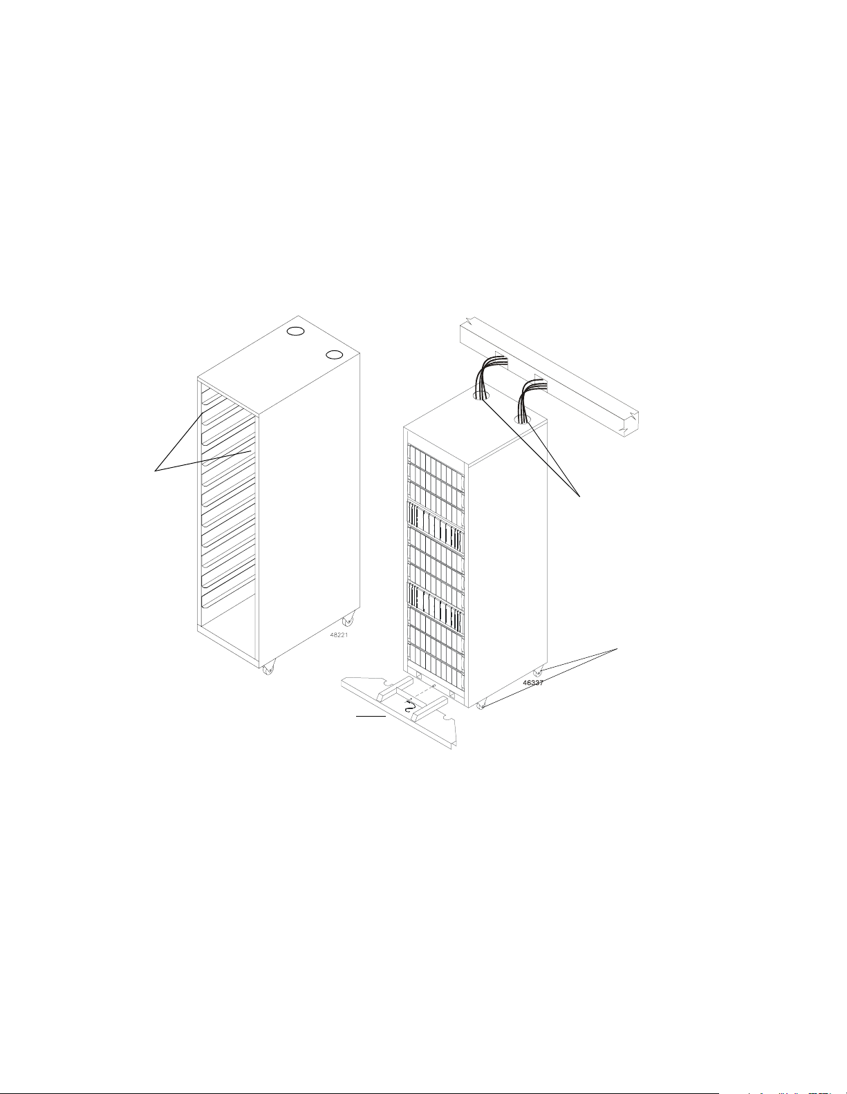
Cabinet Features
The rackmount cabinet (Figure 1-1) has a detachable back door and standard Electronic
Industry Association (EIA) rails, which provide mounting holes for installing 19-inch wide
devices. The cabinet has four roller casters and four adjustable guides (located beneath the
cabinet) for moving and leveling the cabinet during installation and relocation. Newer
models of this cabinet have interface cable access holes on the top and a removable stability
foot that prevents the cabinet from tipping when it is moved.
Standard
EIA Rails
Empty Cabinet
Removable Stability Foot
(not available on all models)
Figure 1-1 72-inch Cabinet
Cable Access Holes
(not available on all
models)
Roller Casters
Populated Cabinet
1-2 Command Module and Drive Module Site Preparation Guide
Page 13

. . . . . . . . . . . . . . . . . . . . . . . . . . . . . . . . . . . . . . . . . . . . . . . . . . . . . . . . . . . . . . . Cabinet Features
You can customize the cabinet to meet your data storage needs, based on performance,
capacity, and availability requirements. The cabinet contains two AC power distribution
boxes and can support a combination of twelve modules. The cabinet will ship with a
maximum of three command modules installed.
The command module is a rackmount unit containing two controllers, a battery,
•
redundant cooling fans and power supplies.
The array module may contain up to fourteen drives, redundant fans and power
•
supplies, and two controllers.
The drive module may contain up to fourteen drives, redundant fans and power
•
supplies, and an Environmental Service Module (ESM).
Command Module and Drive Module Site Preparation Guide 1-3
Page 14
72-Inch Cabinet Site Preparation . . . . . . . . . . . . . . . . . . . . . . . . . . . . . . . . . . . . . . . . . . . . . . . . . . .
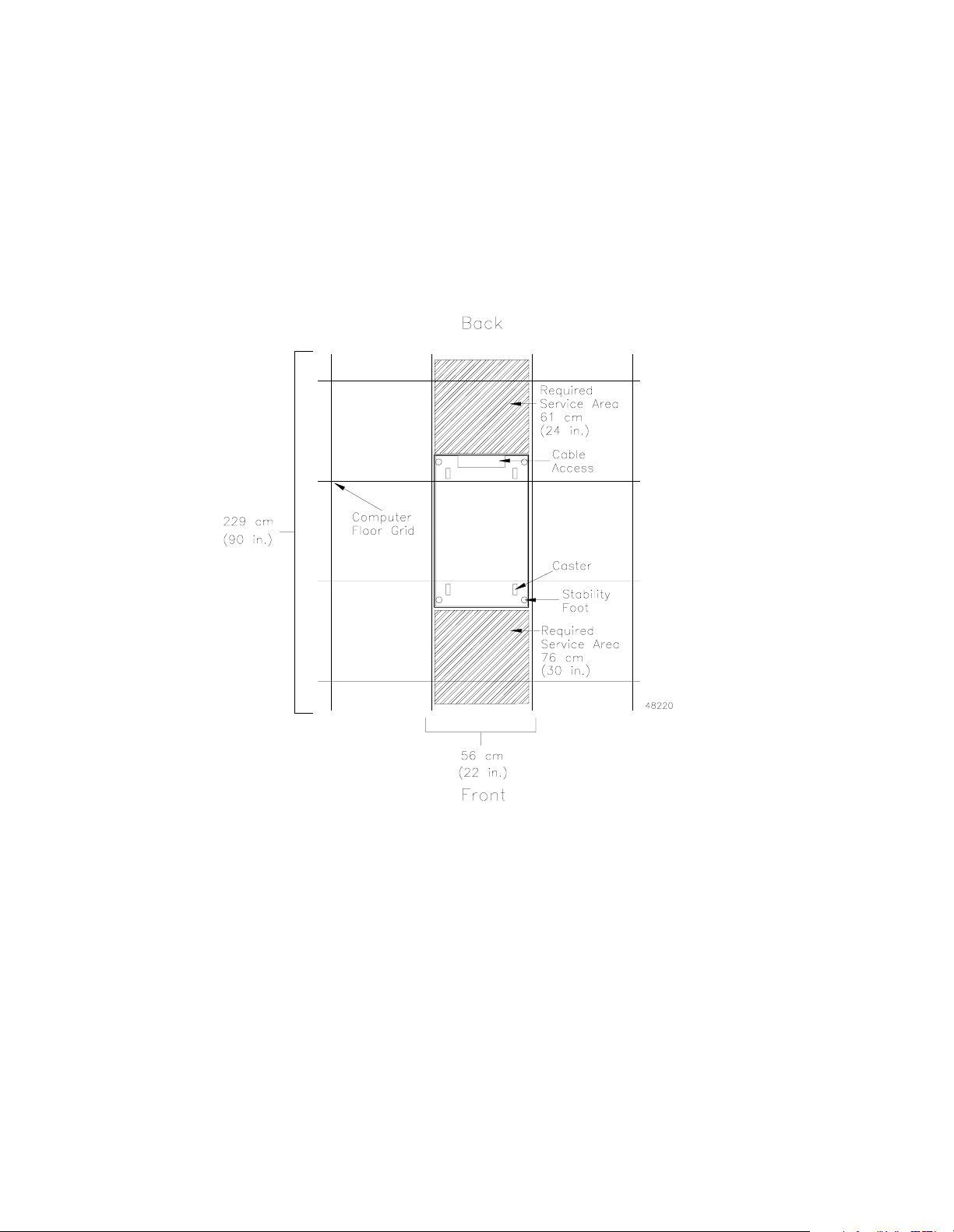
Area Requirements
The floor area at the installation site must provide enough stability to support the weight
of the cabinet and installed devices, sufficient space to install and service the cabinet and
components, and sufficient ventilation to provide a free flow of air to the cabinet. Airflow
in the cabinet is from the front to back. See Figure 1-2 for more information.
Figure 1-2 Cabinet Area Requirements
1-4 Command Module and Drive Module Site Preparation Guide
Page 15

. . . . . . . . . . . . . . . . . . . . . . . . . . . . . . . . . . . . . . . . . . . . . . . . . . . . . . . . . . . . . .Area Requirem ents
Weights
The total weight depends on the type and quantity of modules installed in the cabinet.
Tab le 1 -1 lists the overall weight of the cabinet, plus the maximum weight for each module.
Use these weights to estimate the total weight of your system, based on the number of
modules installed in the cabinet.
Table 1-1 Cabinet, Crate, and Module Weights
Cabinets and Modules Unit Weight
Cabinet Empty 123.0 kg (270.0 lb)
Pallet and Packaging
1
Empty 98.0 kg (215.0 lb)
E2400 10x Array Module
Deskside, Low Profile (LP) drives
E2400 10x Array Module
Deskside, Half Height (HH) drives
E2400 10x Array Module
Rackmount, LP drives
E2400 10x Array Module
Rackmount, HH drives
E2400 14x Array Module
Deskside, LP drives
E2400 14x Array Module
Rackmount, LP drives
FC-1 10x Drive Module
Deskside, LP drives
FC-1 10x Drive Module
Deskside, HH drives
FC-1 10x Drive Module
Rackmount, LP drives
FC-1 10x Drive Module
Deskside, HH drives
2
Maximum 50.8 kg (112 lb)
Maximum 54.4 kg (120.0 lb)
3
Maximum 38.9 kg (86.4 lb)
Maximum 42.3 kg (94.0 lb)
Maximum 52.84 kg (116.5 lb)
Maximum 40.95 kg (90.5 lb)
Maximum 44.5 kg (98.0 lb)
Maximum 47.8 kg (105.0 lb)
Maximum 38.3 kg (84.4 lb)
Maximum 41.7 kg (92.0 lb)
FC-1 14x Drive Module
Rackmount, LP drives
FC-2 14x Drive Module
Rackmount, LP drives
Maximum 40.95 kg (90.5 lb)
Maximum 30.87 kg (68 lb)
E4400 Command Module Maximum 55.6 kg (122.3 lb)
E4600 or E5600 Command Module Maximum 43.99 kg (97.0 lb)
1
Add for international shipments only
2
Low-Profile drives
3
Half-Height drives
Command Module and Drive Module Site Preparation Guide 1-5
Page 16
72-Inch Cabinet Site Preparation . . . . . . . . . . . . . . . . . . . . . . . . . . . . . . . . . . . . . . . . . . . . . . . . . . .
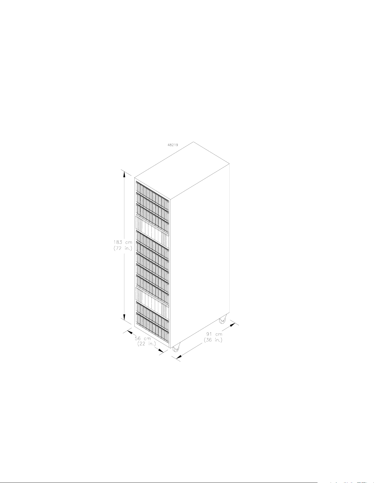
Dimensions
The cabinet has the following dimensions (Figure 1-3), excluding the removable stability
foot:
Height – 183 cm (72 in.)
•
Width – 56 cm (22 in.)
•
Depth – 91 cm (36 in.)
•
Figure 1-3 Cabinet Dimensions
1-6 Command Module and Drive Module Site Preparation Guide
Page 17

. . . . . . . . . . . . . . . . . . . . . . . . . . . . . . . . . . . . . . . . . . . . . . . . . . . . . . Environmental Requirements
Environmental Requirements
The cabinet is designed to operate in the environment defined in Ta ble 1- 2.
Table 1-2 Cabinet Environmental Requirements
Environment Requirements
Altitude Operating Range Storage Range Transit Range
Below Sea Level 30.5 m (100 ft.) 30.5 m (100 ft.) 30.5 m (100 ft.)
Above Sea Level
3048 m
(10,000 ft.)
3048 m
(10,000 ft.)
12,000 m
(40,000 ft.)
Temperature Operating Range Storage Range Transit Range
Te m pe r a t ur e
Range
Temperature
Change
°
C to 35° C
10
°
F to 104° F)
(50
°
C per hour
10
°
F per hour)
(21
°
-10
C to 65° C
°
F to 149° F)
(140
°
15
C per hour
°
F per hour)
(31
°
-40
°
F to 149° F)
(-40
°
20
C per hour
°
F per hour)
(42
to 65° C
Relative Humidity Operating Range Storage Range Transit Range Maximum Allowed
No Condensation 20% to 80% 10% to 90% 5% to 95%
Dew Point
°
28
C (82° F)
Humidity Gradient 10% per hour
Noise Steady/Non-Steady Normal Operation
Level 6.8 bels 65 dBA
1
Configuration B1Configuration C
3.23 kVA
2.90 kVA
3202 W
10,934 Btu/hr
9788 Btu/hr
2866 W
Heat Dissipation
Component
Configuration A
1.62 kVA
1
LP Drives
2
1601 W
5467 Btu/hr
1
1.69 kVA
HH Drives
2
1677 W
5727 Btu/hr
1
These are kVA, W, and Btu calculations for three configurations containing Low-Profile (LP) and Half-Height (HH)
drives, including:
Configuration A contains 1 command module and 5 drive modules
Configuration B contains 2 command modules and 10 drive modules
Configuration C contains 3 command modules and 8 drive modules
2
LP drives are 1.0 inch tall; HH drives are 1.6 inches tall.
3.39 kVA
3354 W
11,454 Btu/hr
3.02 kVA
2988 W
10,205 Btu/hr
Command Module and Drive Module Site Preparation Guide 1-7
Page 18

72-Inch Cabinet Site Preparation . . . . . . . . . . . . . . . . . . . . . . . . . . . . . . . . . . . . . . . . . . . . . . . . . . .
Power Requirement s
This section provides information regarding power requirements, AC power distribution
box specifications, ladder cord and power cord routing instructions, and site wiring
conditions.
The AC power source must provide the correct voltage, current, and frequency specified
on the manufacturer’s nameplate. Ta bl e 1- 3 shows the internal AC power requirements for
rackmount cabinets.
Table 1-3 Power Requirements
Unit/Component Requirements
Domestic International
AC Power 250 VAC, 30 A 230 VAC, 32 A
AC Plug NEMA L6-30P, locking plug IEC 309 locking plug
Receptacle 6-30R, receptacle IEC 309 receptacle
Circuit Breaker 25 A
Vol tag e Ra nge 180 to 257 VAC
Frequency 49 to 50.5 Hz or 59 to 60.6 Hz
Current
(specified frequency)
Operational Current
LP Drives
HH Drives
Configuration A
2
2
220 VAC, 50/60 Hz
1
Configuration B1Configuration C
7.35 A 14.70 A 13.16 A
7.70 A 15.40 A 13.72 A
LP Drives 10.95 A 21.90 A 22.20 A
Surge Current
HH Drives 11.45 A 22.90 A 23.00 A
1
Power specifications for three configurations containing Low-Profile (LP) and Half-Height (HH) drives, including:
Configuration A contains 1 command module and 5 drive modules
Configuration B contains 2 command modules and 10 drive modules
Configuration C contains 3 command modules and 8 drive modules
2
LP drives are 1.0 inch tall; HH drives are 1.6 inches tall.
1
1-8 Command Module and Drive Module Site Preparation Guide
Page 19
. . . . . . . . . . . . . . . . . . . . . . . . . . . . . . . . . . . . . . . . . . . . . . . . . . . . . . . . . . . . Power Requirements
AC Power Distribution Boxes
The cabinet has two identical AC power distribution boxes with two separate power cords
(Figure 1-4). Depending on the configuration ordered, each box supports either domestic
or international units and includes the following features:
One domestic plug (NEMA L6-30P, 30 A, 220 VAC) or one international plug
•
(IEC 309, 32 A, 3-pin, 230 VAC)
One circuit breaker (25 A)
•
Two power outlets (IEC 320, 16 A, C-19, filtered individually for international and
•
domestic EMC compliance)
Support for up to 12 attachments per box (24 per cabinet) using two ladder cables
•
(refer to “Ladder Cords” on page 1-10)
AC Power
Distribution Boxes
AC Power Distribution Box
Power Cords
Figure 1-4 Cabinet AC Distribution
Command Module and Drive Module Site Preparation Guide 1-9
Page 20
72-Inch Cabinet Site Preparation . . . . . . . . . . . . . . . . . . . . . . . . . . . . . . . . . . . . . . . . . . . . . . . . . . .
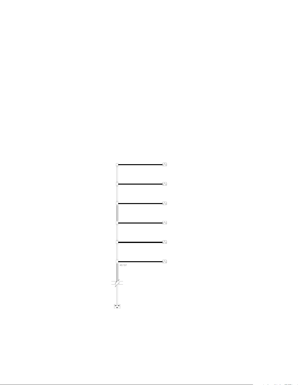
Ladder Cords
Each AC power distribution box outlet supports one ladder cord (Figure 1-5) that you can
connect to a maximum of six modules. You may connect up to twelve 220/230 VAC
modules to each AC power distribution box for a maximum of twenty-four power
attachments inside the cabinet.
Although the cabinet may not be fully populated when shipped, the cabinet is shipped with
two ladder cords. Each cord has the following specifications:
Cord – 10 A per cord (1.67 A per connection if all are used)
•
Input Connector – IEC 320, C-19, 16 A, 250 VAC
•
Plugs – IEC 320, C-14, 10 A, 250 VAC
•
Ladder Step – 5.25 inches between connections
•
Cord Routing – Route cords between the mounting rails and side skins of cabinet
•
Figure 1-5 Cabinet Ladder Cord
1-10 Command Module and Drive Module Site Preparation Guide
Page 21
. . . . . . . . . . . . . . . . . . . . . . . . . . . . . . . . . . . . . . . . . . . . . . . . . . . . . . . . . . . . Power Requirements
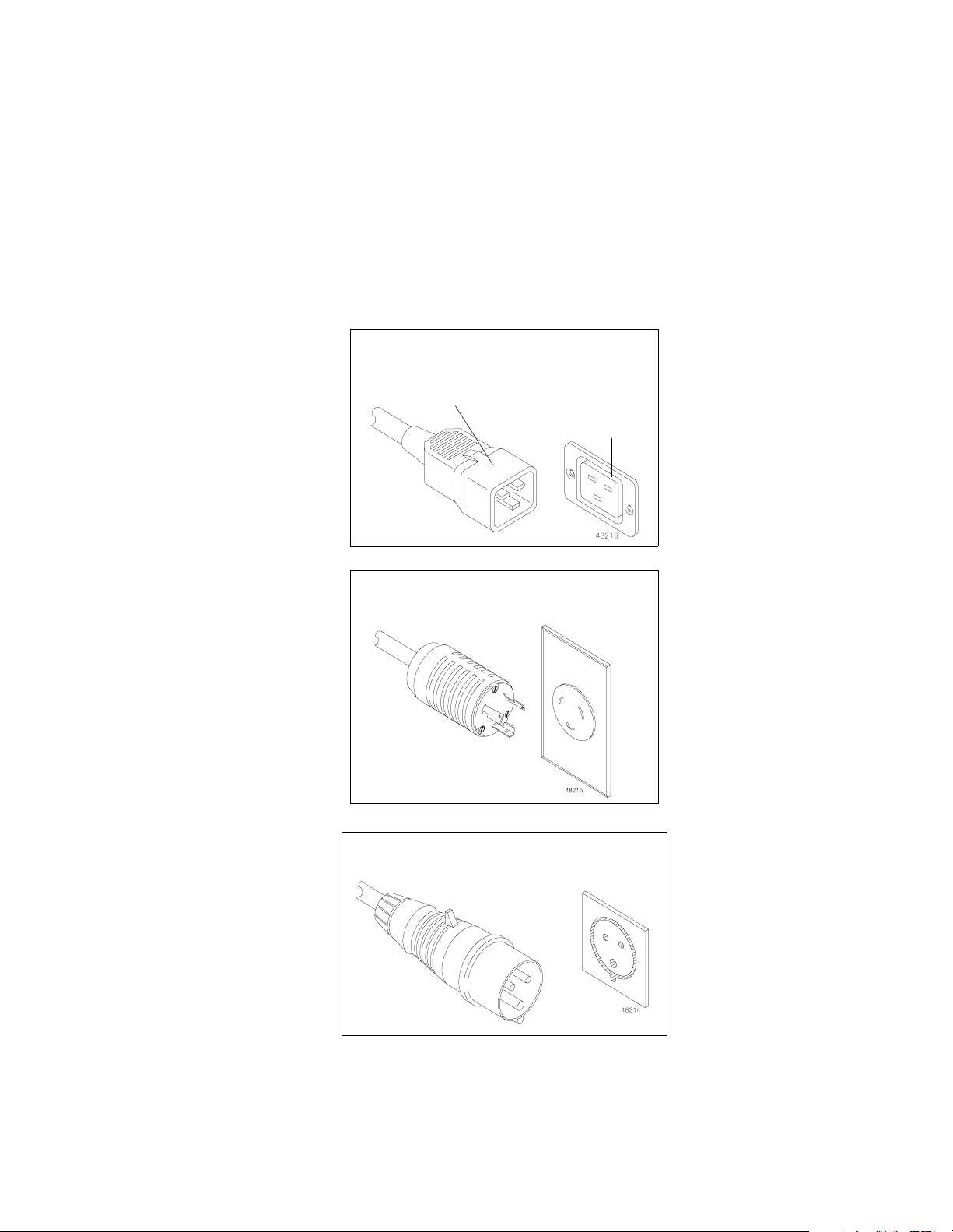
Power Cords and Receptacles
The cabinet is shipped with two power cords: one for domestic (inside USA) use, the other
for international (outside USA) use. Each power cord connects to an independent 25 A
circuit breaker and an AC power distribution box. The AC power distribution box has two
outlets for connecting the power cords from modules installed in the cabinet to an
independent power source outside of the cabinet. Figure 1-6 shows these receptacles.
250 VAC, 16 A, IEC 320-C19 Cord
From AC Power
Distribution Box
Independent
External
Power S ource
250 VAC, 30 A, NEMA L6-30 Cord
(Domestic)
230 VAC, 32 A, IEC 309 Cord
(International)
Figure 1-6 Types of 72-Inch Cabinet Power Cords and Receptacles
Command Module and Drive Module Site Preparation Guide 1-11
Page 22

72-Inch Cabinet Site Preparation . . . . . . . . . . . . . . . . . . . . . . . . . . . . . . . . . . . . . . . . . . . . . . . . . . .
Site Wiring
The cabinet’s AC power distribution boxes use common industrial wiring. Consider the
following information when preparing the cabinet installation site:
AC power source – The AC power source must provide the correct voltage, current, and
•
frequency specified on the manufacturer’s nameplate.
Earth ground – You must have an earth grounding conductor to the cabinet’s power
•
receptacles.
Circuit overloading – Ensure the power circuits and associated circuit breakers provide
•
sufficient power and overload protection. To prevent possible damage to the AC power
distribution boxes and other components in the cabinet, use an external, independent
power source which is isolated from large switching loads (such as air conditioning
motors, elevator motors, and factory loads).
Module power distribution – There are two accessory outlets inside the cabinet for
•
module power distribution. All units attached to these outlets must be auto-ranging
between 180 through 257 VAC, 50-60 Hz.
Power interruptions – The cabinet and its modules will withstand the following
•
applied voltage interruptions (with or without an integrated UPS):
Input transient – 50% of nominal voltage
•
Duration – one half cycle
•
Maximum frequency – once every ten seconds
•
Power failures – After a total power failure, the modules within the cabinet will
•
automatically perform a power-up recovery without operator intervention after power
is restored.
1-12 Command Module and Drive Module Site Preparation Guide
Page 23

Command Module Site Preparation
This chapter provides technical specifications and information you will need to prepare a
site before installing the E4400, E4600, and the E5600 command modules. This chapter
provides information you will use to determine installation, service, and operating floor
space requirements; heating and air conditioning specifications; voltage and power
requirements; and adapter, module, transceiver, and cabling specifications for interface
connectors.
Chapter 2
Command Module and Drive Module Site Preparation Guide 2-1
Page 24

Command Module Site Preparation . . . . . . . . . . . . . . . . . . . . . . . . . . . . . . . . . . . . . . . . . . . . . . . . .
Area Requirements
The floor space at the installation site must provide enough strength to support the weight
of the command module and associated equipment, sufficient space to install, operate, and
service the command module, and sufficient ventilation to provide a free flow of air to the
unit.
Weights
The total weight of the command module depends on the number of components installed
Refer to Tab le 2- 1, Ta bl e 2 -2 , and Tab le 2-3 for more information.
Table 2-1 E4400 Command Module Weight
Unit Unit Weight
Rackmount Command
Module
Maximum
1
Shipping
Weight
Empty Unit
2
Unit Weight
43.99 kg (97.0 lb) 57.2 kg (125.9 lb) 16.1 kg (35.8 lb) 30.8 kg (67.8 lb)
3
Shipping
Battery 9.7 kg (21.4 lb) 11.8 kg (26.0 lb)
Controller 3.0 kg (6.6 lb) 5.0 kg (11.0 lb)
Controller Fan 0.9 kg (1.9 lb) 2.3 kg (5.0 lb)
Power Supply 1.5 kg (3.3 lb) 2.9 kg (6.5 lb)
Fan Communications
Module
1.84 kg (4.06 lb) 2.46 kg (5.44 lb)
Not applicable.
GBIC Minihub 0.567 kg (1.25 lb) 0.712 kg (1.57 lb)
DB-9 Minihub 0.567 kg (1.25 lb) 0.712 kg (1.57 lb)
1
Maximum weight equals a command module with all canisters installed (fully loaded).
2
Shipping weight equals the empty or maximum weight of the command module, plus all shipping materials.
3
Empty weight equals a command module with all canisters removed.
Weight
2
2-2 Command Module and Drive Module Site Preparation Guide
Page 25

. . . . . . . . . . . . . . . . . . . . . . . . . . . . . . . . . . . . . . . . . . . . . . . . . . . . . . . . . . . . . .Area Requirem ents
Table 2-2 E4600 Command Module Weight
Unit Unit Weight
Rackmount
Command Module
Maximum
1
Shipping
2
Weight
Empty Unit
Weight
43.99 kg (97.0 lb) 57.2 kg (125.9 lb) 18.07 kg (39.84 lb) 30.8 kg (67.8 lb)
3
Shipping2 Weight
Battery 10.89 kg (24.0 lb) 12.97 kg (28.6 lb)
Controller 3.0 kg (6.6 lb) 5.0 kg (11.0 lb)
Controller Fan 0.9 kg (1.9 lb) 2.3 kg (5.0 lb)
Power Supply 1.5 kg (3.3 lb) 2.9 kg (6.5 lb)
Fan Communications
Module
1.84 kg (4.06 lb) 2.9 kg (6.3 lb)
Not applicable.
SFP Minihub 0.567 kg (1.25 lb) 0.6 kg (1.5 lb)
1
Maximum weight equals a command module with all canisters installed (fully loaded).
2
Shipping weight equals the empty or maximum weight of the command module, plus all shipping materials.
3
Empty weight equals a command module with all canisters removed.
Table 2-3 E5600 Command Module Weight
Unit Unit Weight
Maximum
Shipping
1
2
Weight
Weight
Empty Unit
3
Shipping2 Weight
Rackmount
Command Module
43.99 kg (97.0 lb) 57.2 kg (125.9 lb) 18.07 kg (39.84 lb) 30.8 kg (67.8 lb)
Battery 10.89 kg (24.0 lb) 12.97 kg (28.6 lb)
Controller 3.0 kg (6.6 lb) 5.0 kg (11.0 lb)
Controller Fan 0.9 kg (1.9 lb) 2.3 kg (5.0 lb)
Power Supply 1.5 kg (3.3 lb) 2.9 kg (6.5 lb)
Fan Communications
Module
1.84 kg (4.06 lb) 2.9 kg (6.3 lb)
Not applicable.
SFP Minihub 0.567 kg (1.25 lb) 0.6 kg (1.5 lb)
1
Maximum weight equals a command module with all canisters installed (fully loaded).
2
Shipping weight equals the empty or maximum weight of the command module, plus all shipping materials.
3
Empty weight equals a command module with all canisters removed.
Command Module and Drive Module Site Preparation Guide 2-3
Page 26

Command Module Site Preparation . . . . . . . . . . . . . . . . . . . . . . . . . . . . . . . . . . . . . . . . . . . . . . . . .
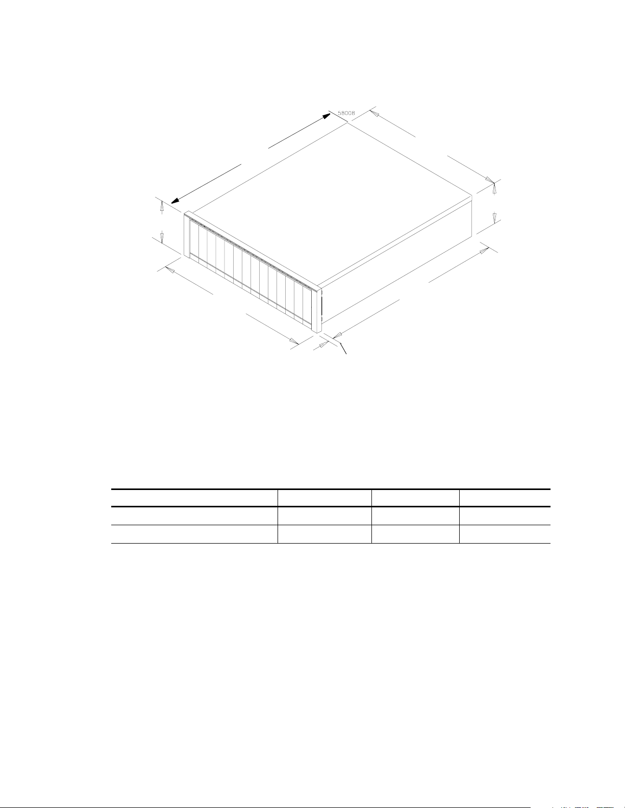
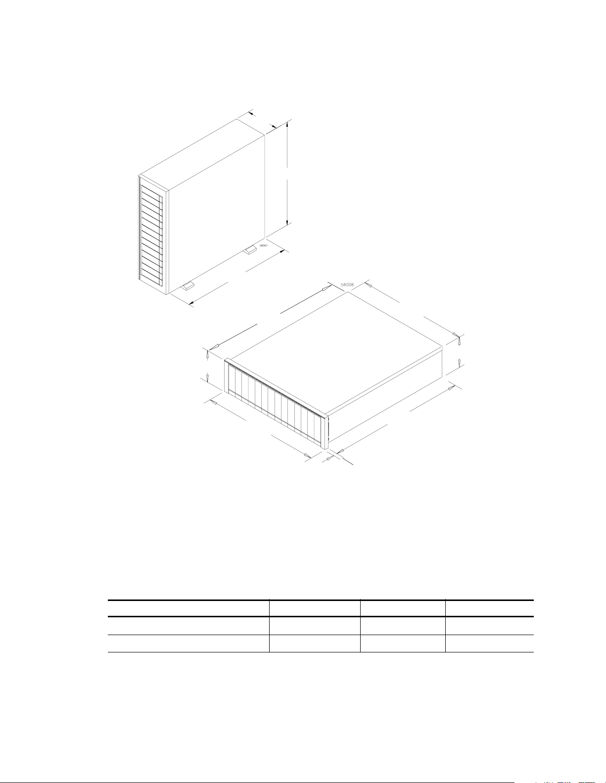
Dimensions
Command module dimensions are the same for each model (Figure 2-1).
44.5 cm (17.5 in.)
Rackmount
17.5 cm (6.9 in.)
61.0 cm (24.0 in.)
48.2 cm (19.0 in.)
2.0 cm (0.8 in.)
Figure 2-1 Command Module Dimensions
Shipping C a rton Dimensions
Shipping carton dimensions include the height of the pallet and are the same for all models
(Tab le 2 -4 ).
Table 2-4 Command Module Shipping Carton Dimensions
Carton Height Carton Width Carton Depth
44.4 cm (17.5 in.) 62.2 cm (24.5 in.) 78.7 cm (31.0 in.)
2-4 Command Module and Drive Module Site Preparation Guide
Page 27
. . . . . . . . . . . . . . . . . . . . . . . . . . . . . . . . . . . . . . . . . . . . . . . . . . . . . . . . . . . . . .Area Requirem ents
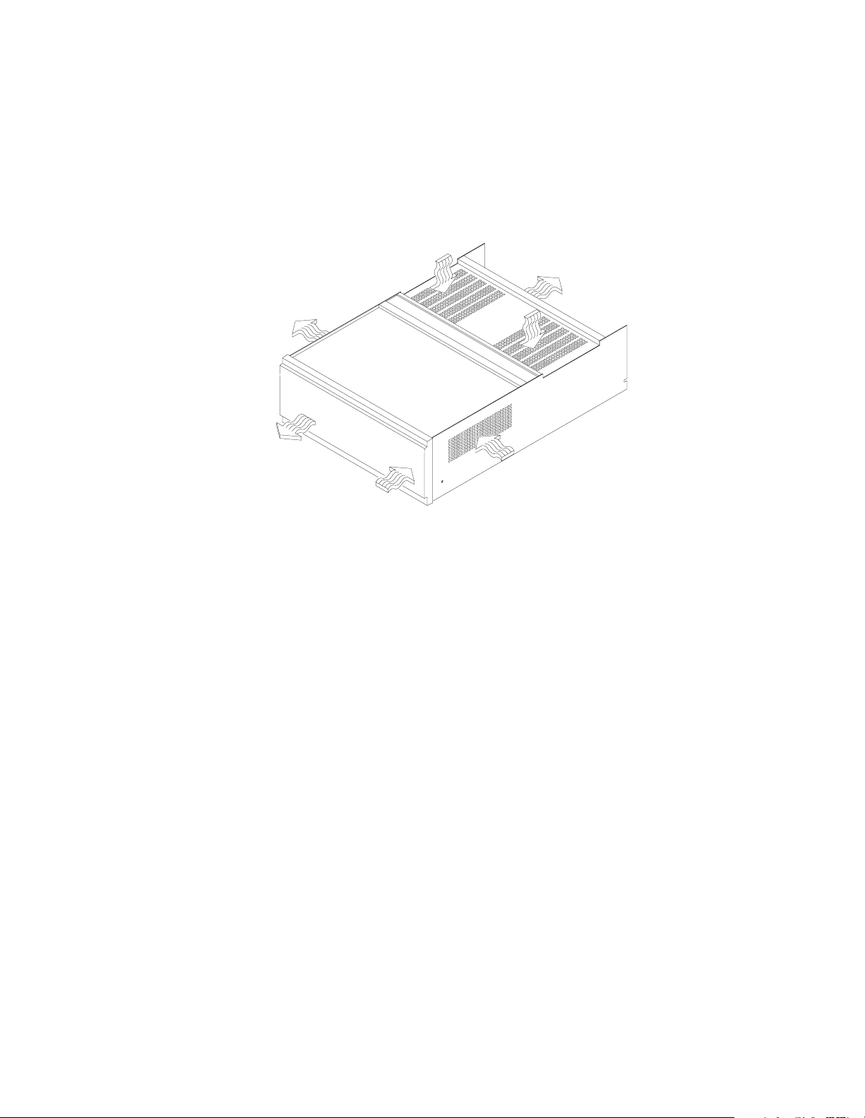
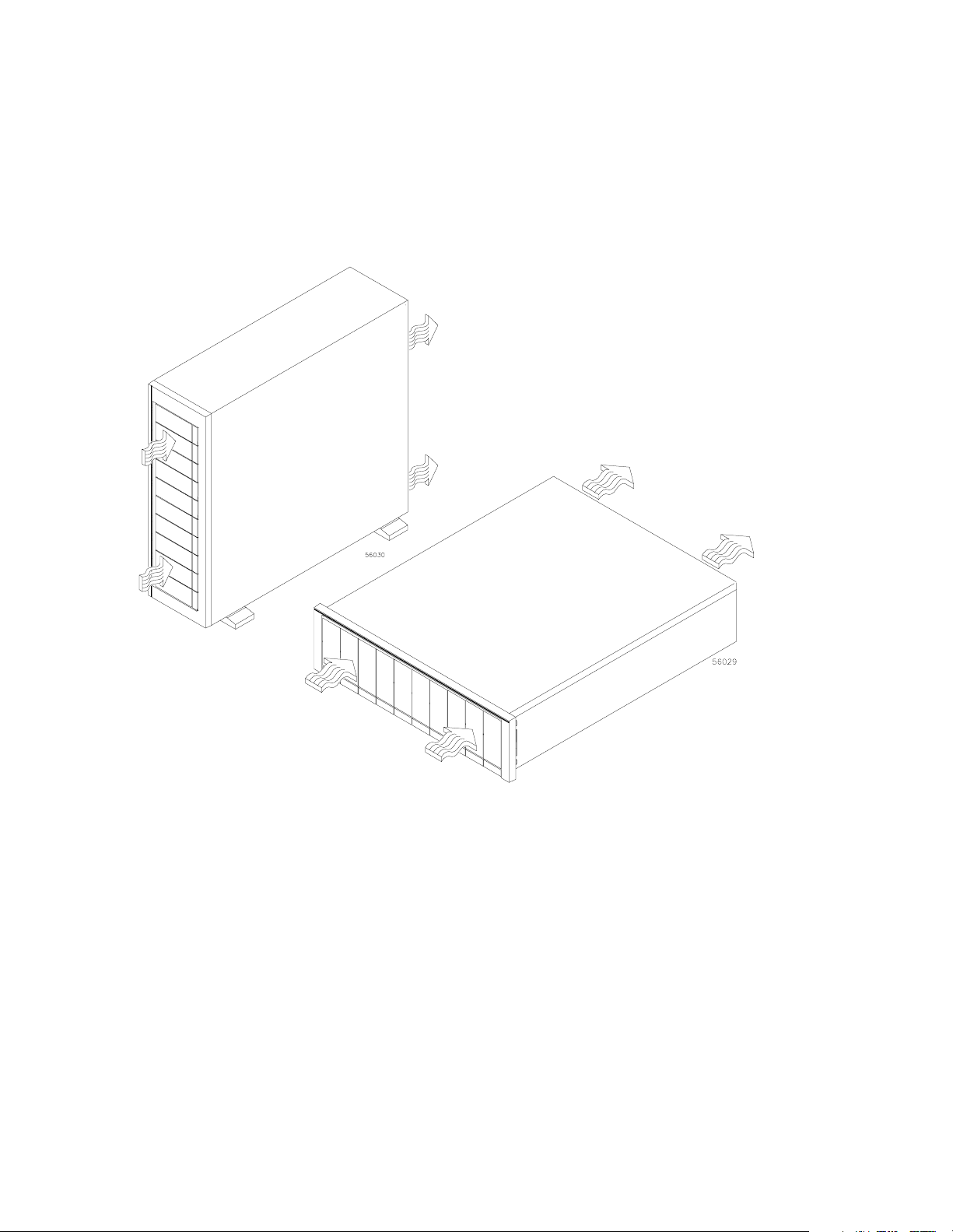
Airflow
For proper ventilation, allow at least 2 feet of clearance in front of and behind the
command module (Figure 2-2).
Back
Front
Figure 2-2 Command Module Airflow
Command Module and Drive Module Site Preparation Guide 2-5
Page 28

Command Module Site Preparation . . . . . . . . . . . . . . . . . . . . . . . . . . . . . . . . . . . . . . . . . . . . . . . . .
Environmental Requirements
The command module is designed to operate in the environment defined in Ta bl e 2 -5 and
Tab le 2 -6 .
Table 2-5 Command Module Environmental Requirements
Condition Parameter
Operating Range
Maximum Rate of Change
Storage Range
Te mp er a tu r e
Maximum Rate of Change
Tra n si t Ran ge
Maximum Rate of Change
Operating Range 10% to 90% 20% to 80%
Storage Range 10% to 93%
Relative Humidity
No condensation
Tra n si t Ran ge 5% to 9 5%
Maximum Dew Point
Maximum Gradient 10% per hour
Requirement
E4400 E4600 E5600
°
C to 43° C
0
°
(32
F to 109° F)
°
C to 60° C
-40
°
F to 140°
(-40
F)
°
C (18° F) per hour
10
°
C to 65° C (14° F to 149° F)
-10
°
15
C (27° F) per hour
°
20
C (36° F) per hour
°
26
°
0
°
(32
-40
(-40
C (79° F)
C to 40° C
F to 104° F)
°
C to 65° C
°
F to 149° F)
Sound
Sound Power 6.5 bels
Sound Pressure 65 dBA
Altitude
(Above Sea Level)
Altitude
(Below Sea Level)
1
If you plan to operate a command module at altitudes between 1000 m to 3000 m (3280 ft. to 9850 ft.) above sea level,
lower the environmental temperature 1.7° C (3.3° F) for every 1000 m (3280 ft.) above sea level.
Operating and Storage
1
Transit 12,000 m (40,000 ft.)
Operating, Storage,
and Transit
3000 m (9840
ft.)
3048 (10,000 ft.)
30.5 m (100 ft.)
2-6 Command Module and Drive Module Site Preparation Guide
Page 29

. . . . . . . . . . . . . . . . . . . . . . . . . . . . . . . . . . . . . . . . . . . . . . . . . . . . . . Environmental Requirements
Table 2-6 Command Module Heat Dissipation
Model Heat Dissipation
E4400 657.5 Btu/hr (0.1925 kVA or 192.5 W)
E4600 790.0 Btu/hr (0.2333 kVA or 231.0 W)
E5600 786.6 Btu/hr (0.2300 kVA or 230.0 W)
Command Module and Drive Module Site Preparation Guide 2-7
Page 30

Command Module Site Preparation . . . . . . . . . . . . . . . . . . . . . . . . . . . . . . . . . . . . . . . . . . . . . . . . .
Power Requirement s
This section provides information regarding command module AC power requirements,
power cord routing instructions, and site wiring conditions.
The AC power source must provide the correct voltage, current, and frequency specified
on the manufacturer’s nameplate. Internal AC power units for rackmount cabinets must
be able to handle the power requirements for these units (Ta bl e 2 -7 ).
Table 2-7 Command Module Power Requirements
Item Unit of Measure Requirement
Circuit Breaker Slow-blow Fuse 3 A per Power Supply
Nominal Voltage 90 to 264 VAC
Frequency 50 to 60 Hz
AC Power
1
Typical current at 240 VAC, 60 Hz at 0.70 power efficiency, 0.99 power factor.
Operating Current
Maximum Surge Current
1 A
2 A
1
1
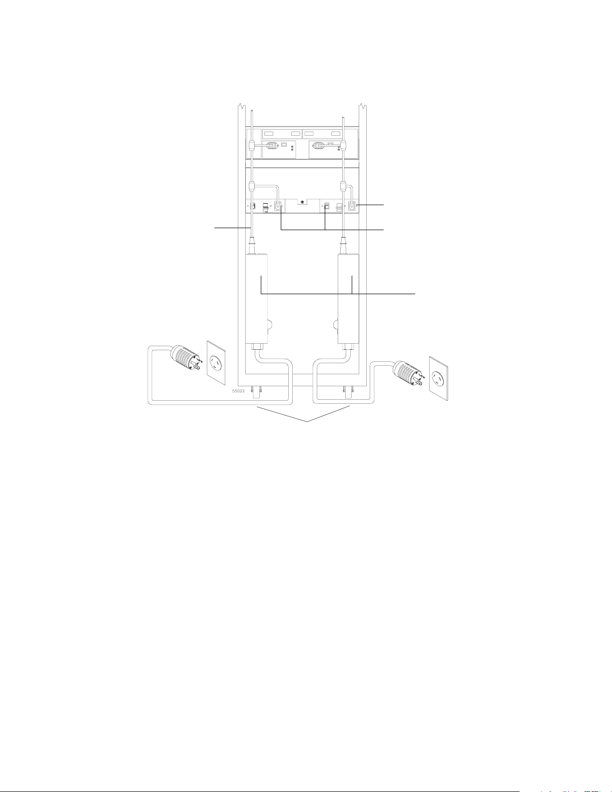
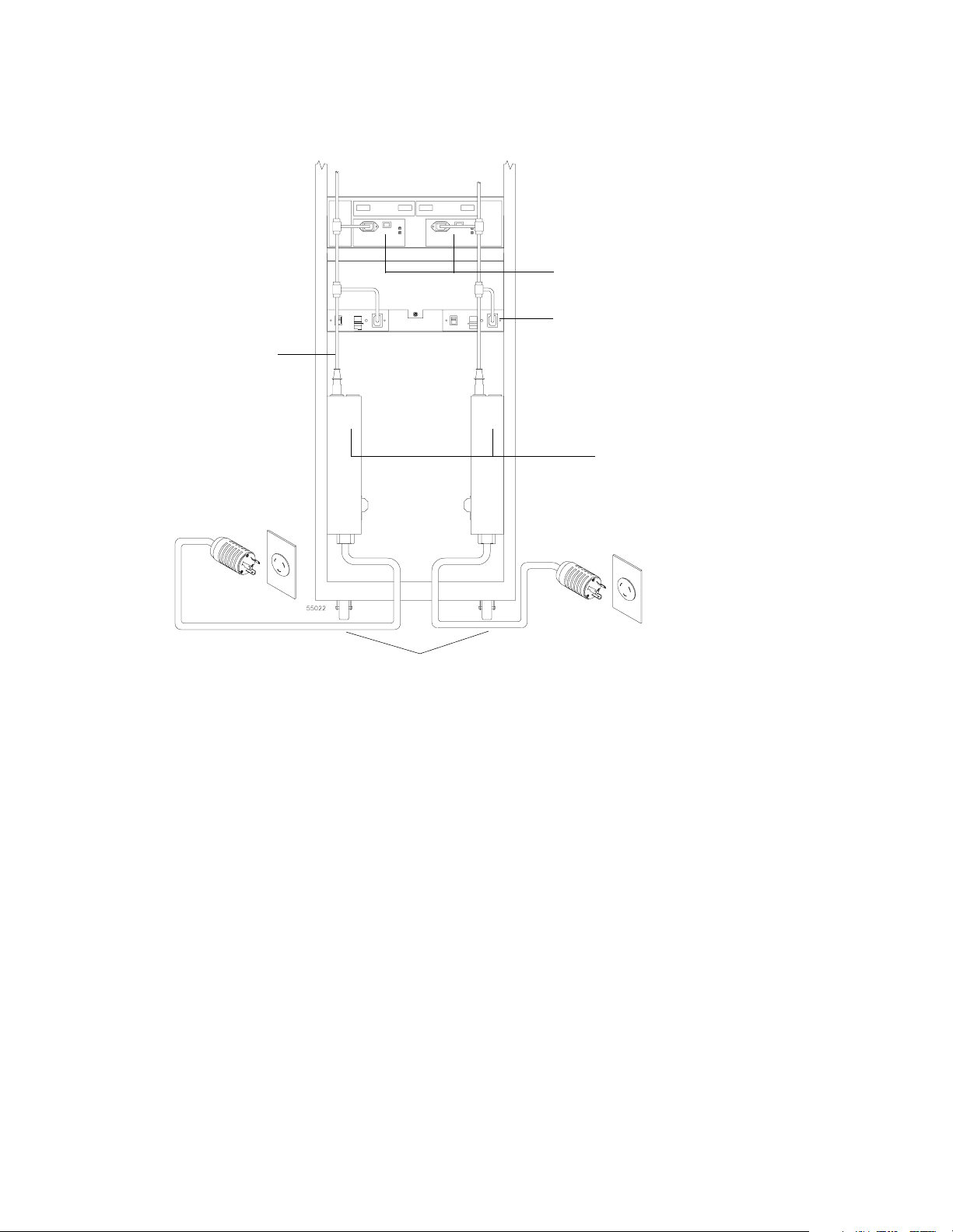
Power Cord Routing
All modules are shipped with two AC power cords that are appropriate for use in a typical
outlet in the destination country. Each power cord connects one of the power supplies in a
module to an independent, external power source, such as a wall receptacle or
uninterruptible power supply (UPS). If you have a rackmount cabinet with internal power
cabling, such as a ladder cable, you do not need these power cords.
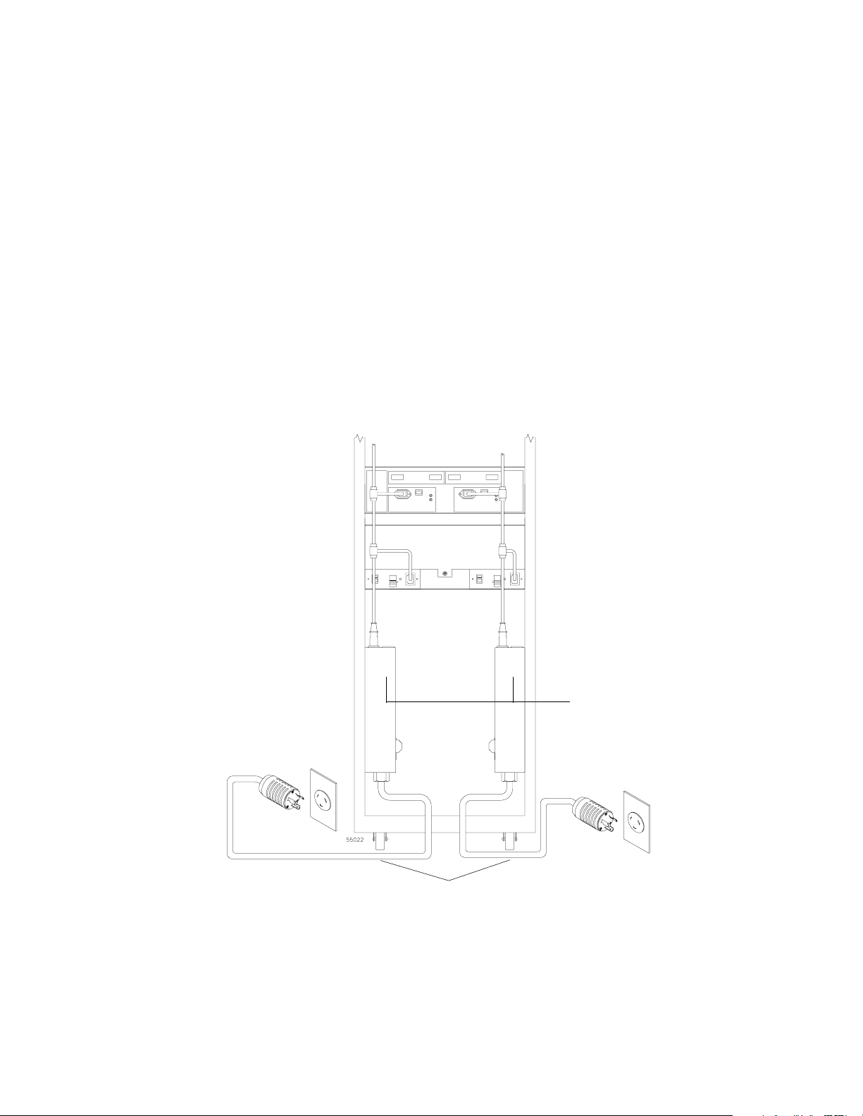
A rackmount cabinet can have up to two AC power distribution boxes with separate power
cords (Figure 2-3). To ensure redundancy, each power cord must connect to an
independent, external power source. Each AC power distribution box has a ladder cable
that runs up the inside of the cabinet and connects to one of the power supplies in each
module.
Figure 2-4 on page 2-10 shows the power cords and receptacles for domestic (inside USA)
and international use (outside USA).
2-8 Command Module and Drive Module Site Preparation Guide
Page 31
. . . . . . . . . . . . . . . . . . . . . . . . . . . . . . . . . . . . . . . . . . . . . . . . . . . . . . . . . . . . Power Requirements
Ladder Cord Connector
Ladder Cord
Figure 2-3 Redundant Command Module AC Power Connections
Command Module Power Supplies
AC Power
Distribution Boxes
AC Power Distribution Box
Power Cords
Command Module and Drive Module Site Preparation Guide 2-9
Page 32

Command Module Site Preparation . . . . . . . . . . . . . . . . . . . . . . . . . . . . . . . . . . . . . . . . . . . . . . . . .
250 VAC, 16 A, IEC 320-C19 Cord
From AC Power
Distribution Box
Independent
External
Power S ource
250 VAC, 30 A, NEMA L6-30 Cord
(Domestic)
230 VAC, 32 A, IEC 309 Cord
(International)
Figure 2-4 Types of 72-Inch Cabinet AC Power Cords and Receptacles
2-10 Command Module and Drive Module Site Preparation Guide
Page 33

. . . . . . . . . . . . . . . . . . . . . . . . . . . . . . . . . . . . . . . . . . . . . . . . . . . . . . . . . . . . Power Requirements
Site Wiring
The command module uses wide-ranging, redundant power supplies that automatically
accommodate voltages to the AC power source. The power supplies operate at a range
between 90 VAC and 264 VAC, and at a minimum frequency of 50 Hz and a maximum
frequency of 60 Hz. The power supplies meet standard voltage requirements for both
domestic (inside USA) and international (outside USA) operation. They use standard
industrial wiring with line-to-neutral or line-to-line power connections.
Consider the following information when preparing the command module installation
site:
Earth ground – The unit must be properly grounded, including an earth ground
•
conductor on the AC power source.
Circuit overloading – Ensure the power circuits and associated circuit breakers in the
•
cabinet and building provide sufficient power and overload protection. To prevent
possible damage to the unit, isolate its power source from large switching loads (such as
air conditioning motors, elevator motors, and factory loads).
Power interruptions – The command modules will withstand the following applied
•
voltage interruptions (with or without an integrated UPS):
Input transient – 50% of nominal voltage
•
Duration – one half cycle
•
Frequency – once every 10 seconds
•
Power failures – After a total power failure, the unit will automatically perform a
•
power-up recovery sequence without operator intervention after power is restored.
Command Module and Drive Module Site Preparation Guide 2-11
Page 34

Command Module Site Preparation . . . . . . . . . . . . . . . . . . . . . . . . . . . . . . . . . . . . . . . . . . . . . . . . .
Interface Cables and Connections
This section provides information about command module interface cables, such as GBIC
minihubs and SFP transceivers, and their appropriate connections. See Figure 2-5 and
Figure 2-6 on page 2-14 for command module interface connector examples.
E4400 Command Module
The E4400 command module supports Fibre Channel connections to both hosts and drive
modules. Up to four host minihubs and four drive minihubs, for a maximum of eight
connections, can be installed in each command module. The E4400 supports two types of
minihubs:
GBIC minihub – contains a pair of connectors for attaching either of the following:
•
Optical GBIC module – used with fiber optic cable
•
Copper GBIC module – used with copper fiber cable
•
DB-9 minihub – contains a pair of DB-9 connectors for attaching copper fiber cable
•
Fiber Optic or
Copper Fiber Cable
GBIC Module
Copper Fiber Cable
DB-9 Connector
Figure 2-5 Optical and Copper GBICs
2-12 Command Module and Drive Module Site Preparation Guide
Page 35

. . . . . . . . . . . . . . . . . . . . . . . . . . . . . . . . . . . . . . . . . . . . . . . . . . Interface Cables and Connections
If you order optical GBIC connectors, you will need fiber optic cable. If you order copper
GBIC minihubs or DB-9 minihubs, you will need copper fiber cable. Refer to Tab le 2- 8 for
types and cable lengths available from your local dealer.
Table 2-8 E4400 Command Module Fibre Channel Interface Cables
Cable Data Rate
Fiber optic
Multimode, 50micrometer,
shortwave laser
Copper fiber
Shielded, twisted pair,
electrical signal
Descriptions Order Information
Transfer
Speed
Maximum
Range
Part
Number
Length
006-1086672 2 meter
006-1086416 3 meter
100 MB/s 1062.5 Mb/s 0.5 kilometer
006-1086673 5 meter
006-1086417 10 meter
006-1086682 2 meter
006-1086672 3 meter
100 MB/s 1062.5 Mb/s 30 meters
006-1086483 5 meter
006-1086473 10 meter
Command Module and Drive Module Site Preparation Guide 2-13
Page 36

Command Module Site Preparation . . . . . . . . . . . . . . . . . . . . . . . . . . . . . . . . . . . . . . . . . . . . . . . . .
E4600 and E5600 Command Modules
The E4600 and E5600 command modules support fiber optic connections to both hosts
and drive modules. Up to four host minihubs and four drive minihubs can be installed in a
command module. Each Small Form-factor Pluggable (SFP) minihub has two connectors,
allowing a maximum of sixteen connections. An SFP transceiver (Figure 2-6) attaches to
one end of the fiber optic cable and plugs into the SFP minihub, which is connected to the
command module. The other end of the cable connects to an optical GBIC module in the
drive module.
SFP Transceiver
Figure 2-6 SFP Transceiver and Fiber Optic Cable
Fiber Optic Cable
Refer to Tab le 2- 9 and Table 2-10 for interface connector cable lengths available from your
local dealer.
Table 2-9 E4600 Command Module Fibre Channel Host and Drive Interface Cables
Descriptions Order Information
Cable Data Rate
Fiber optic
50/125UM LC/LC
At least
200 MB/s
Transfer
Speed
At least
2125 Mb/s
Maximum Part Number Length
006-1086713 2 meter
006-1086714 3 meter
006-1086715 5 meter
.03 kilometer
006-1086716 10 meter
006-1086717 25 meter
006-1086718 50 meter
006-1086723 2 meter
006-1086724 3 meter
Fiber optic
50/125UM SC/LC
2-14 Command Module and Drive Module Site Preparation Guide
100 MB/s 1062.5 Mb/s 0.5 kilometer
006-1086725 5 meter
006-1086726 10 meter
006-1086727 25 meter
006-1086728 50 meter
Page 37

. . . . . . . . . . . . . . . . . . . . . . . . . . . . . . . . . . . . . . . . . . . . . . . . . . Interface Cables and Connections
Table 2-10 E5600 Command Module Fibre Channel Host and Drive Interface Cables
Descriptions Order Information
Cable Data Rate
Fiber optic
50/125 um LC/LC
At least
200 MB/s
Transfer
Speed
At least
2125 Mb/s
Maximum
300
kilometer
Part
Number
Length
006-1086713 2 meter
006-1086714 3 meter
006-1086715 5 meter
006-1086716 10 meter
006-1086717 25 meter
006-1086718 50 meter
Command Module and Drive Module Site Preparation Guide 2-15
Page 38

Command Module Site Preparation . . . . . . . . . . . . . . . . . . . . . . . . . . . . . . . . . . . . . . . . . . . . . . . . .
2-16 Command Module and Drive Module Site Preparation Guide
Page 39

Drive Module Site Preparation
This chapter provides technical specifications and information you will need to prepare a
site before installing a FC-1 10x, FC-1 14x, or FC-2 14x drive module. This chapter
provides information you will use to determine installation, service, and operating floor
space requirements; heating and air conditioning specifications; voltage and power
requirements; and adapter, module, transceiver, and cabling specifications for interface
connectors.
Chapter 3
Command Module and Drive Module Site Preparation Guide 3-1
Page 40

Drive Module Site Preparation. . . . . . . . . . . . . . . . . . . . . . . . . . . . . . . . . . . . . . . . . . . . . . . . . . . . . .
Area Requirements
The floor space at the installation site must provide enough strength to support the weight
of the drive module and associated equipment, sufficient space to install, operate, and
service the drive module, and sufficient ventilation to provide a free flow of air to the unit.
Weights
The total weight of the drive module depends on the number of components installed
Refer to Tab le 3- 1, Ta bl e 3 -2 , and Tab le 3-3 for more information.
Table 3-1 FC-1 10x Drive Module Weight
Weight
Unit
Maximum Unit
1
Empty Unit
2
Shipping
3
Drive Module
Deskside Low Profile (LP) drives
Drive Module
Deskside Half Height (HH) drives
Drive Module
Rackmount LP drives
Drive Module
Rackmount HH drives
4
5
44.5 kg (98.0 lb) 23.6 kg (52.0 lb) 59.0 kg (130.0 lb)
47.8 kg (105.0 lb) 23.6 kg (52.0 lb) 62.4 kg (137.0 lb)
38.3 kg (84.4 lb) 12.7 kg (28.0 lb) 43.5 kg (96.0 lb)
41.7 kg (92.0 lb) 12.7 kg (28.0 lb) 47.0 kg (103.6 lb)
LP Drive, 18 GB or 36 GB 1.06 kg (2.34 lb)
HH Drive, 36 GB or 73 GB 1.4 kg (3.08 lb)
ESM 1.7 kg (3.8 lb)
Not applicable.
Power Supply 2.3 kg (5.0 lb)
Fan 1.0 kg (2.3 lb)
1
Maximum weight equals a drive module with all canisters installed (fully loaded).
2
Empty weight equals a drive module with all canisters removed.
3
Shipping weight equals the maximum weight of the drive module, plus all shipping material.
4
Low-Profile drives.
5
Half-Height drives.
3-2 Command Module and Drive Module Site Preparation Guide
Page 41

. . . . . . . . . . . . . . . . . . . . . . . . . . . . . . . . . . . . . . . . . . . . . . . . . . . . . . . . . . . . . .Area Requirem ents
Table 3-2 FC-1 14x Drive Module Weight
Weight
Unit Maximum Unit
Shipping
3
Drive Module
Rackmount Low Profile (LP) drives
Drive Module
Drive-ready Rackmount LP drives
40.95 kg (90.5 lb)
30.5 kg (66.4 lb)
1
2
47.25 kg (105.0 lb)
37.44 kg (83.2 lb)
LP Drive, 18 GB or 36 GB 1.0 kg (2.2 lb)
LP Drive, Blank
Canisters 0.32 kg (0.72 lb)
ESM 1.67 kg (3.7 lb)
Power Supply 2.49 kg (5.5 lb)
Fan 1.0 kg (2.2 lb)
1
Maximum weight equals a drive module with all canisters installed (fully loaded).
2
Drive-ready weight equals a drive module with all canisters installed and blank drives (empty).
3
Shipping weight equals the maximum or drive-ready weight of the drive module, plus all shipping material.
Table 3-3 FC-2 14x Drive Module Weight
Weight
Unit Maximum Unit
Drive Module
Rackmount Low Profile (LP) drives
41.77 kg (92 lb)
1
Shipping
53.57 kg (118 lb)
3
Drive Module
Drive-ready Rackmount LP drives
30.87 kg (68 lb)
2
42.68 kg (94 lb)
LP Drive, 18 GB or 36 GB 1.0 kg (2.2 lb)
LP Drive, 73 GB 1.12 kg (2.46 lb)
LP Drive, Blank
Canisters 0.32 kg (0.72 lb) 0.78 kg (1.72 lb)
ESM 1.59 kg (3.7 lb) 2.04 kg (4.5 lb)
Power Supply 2.45 kg (5.39 lb) 3.56 kg (7.39 lb)
Fan 1.01 kg (2.23 lb) 1.92 kg (4.23 lb)
1
Maximum weight equals a drive module with all canisters installed (fully loaded).
2
Drive-ready weight equals a drive module with all canisters installed and blank drives (empty).
3
Shipping weight equals the maximum or drive-ready weight of the drive module, plus all shipping material.
Command Module and Drive Module Site Preparation Guide 3-3
Page 42

Drive Module Site Preparation. . . . . . . . . . . . . . . . . . . . . . . . . . . . . . . . . . . . . . . . . . . . . . . . . . . . . .
Dimensions
Drive module dimensions for each model differ slightly. See Figure 3-1 and Figure 3-2 for
model descriptions.
16.6 cm (6.5 in.)
52.7 cm (20.7 in.)
13.18 cm (5.2 in.)
56.0 cm (22.0 in.)
44.7 cm (17.6 in.)
12.9 cm (5.08 in.)
55.91 cm (22.0 in.)
48.0 cm (18.9 in.)
1.59 cm (0.625 in.)
Figure 3-1 FC-1 10x Drive Module Dimensions
3-4 Command Module and Drive Module Site Preparation Guide
Page 43
. . . . . . . . . . . . . . . . . . . . . . . . . . . . . . . . . . . . . . . . . . . . . . . . . . . . . . . . . . . . . .Area Requirem ents
59.74 cm (23.52 in.)
44.70 cm (17.60 in)
13.23 cm
(5.21 in.)
56.13 cm (22.1 in.)
48.18 cm (18.97 in.)
3.63 cm (1.43 in.)
Figure 3-2 FC-1 14x and FC-2 14x Drive Module Dimensions
Shipping Carton Dimensions
Shipping carton dimensions include the height of the pallet (Ta bl e 3 -4 ).
12.9 cm
(5.08 in.)
Table 3-4 Drive Module Shipping Carton Dimensions
Model Carton Height Carton Width Carton Depth
FC-1 10x 38.1 cm (15.0 in.) 61.4 cm (24.0 in.) 83.2 cm (32.7 in.)
FC-1 14x and FC-2 14x 44.45 cm (17.5 in.) 62.23 cm (24.5 in.) 74.93 cm (29.5 in.)
Command Module and Drive Module Site Preparation Guide 3-5
Page 44
Drive Module Site Preparation. . . . . . . . . . . . . . . . . . . . . . . . . . . . . . . . . . . . . . . . . . . . . . . . . . . . . .
Airflow
For proper ventilation, allow at least 2 feet of clearance in front of and behind the drive
module (Figure 3-3).
Deskside
Back
Front
Rackmount
Figure 3-3 Drive Module Airflow
3-6 Command Module and Drive Module Site Preparation Guide
Page 45

. . . . . . . . . . . . . . . . . . . . . . . . . . . . . . . . . . . . . . . . . . . . . . . . . . . . . . Environmental Requirements
Environmental Requirements
The drive module is designed to operate in the environment defined in Ta ble 3- 5 and
Table 3-6 on page 3-7.
Table 3-5 Drive Module Environmental Requirements
Condition Parameter
Operating Range
Maximum Rate of Change
Storage Range
Te m pe r a t ur e
Maximum Rate of Change
Tran sit Ran ge
Maximum Rate of Change
Operating Range 20% to 80%
Storage Range 10% to 90%
Relative Humidity
No condensation
Transit Range 5% to 95%
Maximum Dew Point
Maximum Gradient 10% per hour
Sound Power 6.0 bels
Sound
Sound Pressure 60 dBA
Altitude
(Above Sea Level)
Operating and Storage 3000 m (9840 ft.)
1
Transit 12,000 m (40,000 ft.)
Requirement
FC-1 10x, FC-1 14x, and FC-2 14x
°
10
C to 40° C (50° F to 104° F)
°
C (18° F) per hour
10
°
C to 50° C (14° F to 122° F)
-10
°
C (27° F) per hour
15
°
-40
C to 60° C (-40° F to 140° F)
°
C (36° F) per hour
20
°
26
C (79° F)
Altitude
(Below Sea Level)
1
If you plan to operate a drive module at altitudes between 1000 m to 3000 m (3280 ft. to 9850 ft.) above sea level,
lower the environmental temperature 1.7
Model
Operating, Storage, and Transit 30.5 m (100 ft.)
°
C (3.3° F) for every 1000 m (3280 ft.) above sea level.
Table 3-6 Drive Module Heat Dissipation
Low Profile (LP)
18 GB and 36 GB Dri ves
Half Height (HH)
36 GB and 73 GB Drives
FC-1 10x 1036 Btu/hr (0.306 kVA or 303 W) 1070 Btu/hr (0.33 kVA or 313 W)
FC-1 14x 1050 Btu/hr (0.309 kVA or 306 W) Not applicable.
FC-2 14x 1084 Btu/hr (0.320 kVA or 317 W) Not applicable.
Command Module and Drive Module Site Preparation Guide 3-7
Page 46

Drive Module Site Preparation. . . . . . . . . . . . . . . . . . . . . . . . . . . . . . . . . . . . . . . . . . . . . . . . . . . . . .
Power Requirement s
This section provides information regarding drive module AC power requirements, power
cord routing instructions, and site wiring conditions.
The AC power source must provide the correct voltage, current, and frequency specified
on the manufacturer’s nameplate. Internal AC power units for rackmount cabinets must
be able to handle the power requirements for these units. Refer to Table 3- 7, Ta ble 3- 8, and
Table 3-9 on page 3-9 for more information.
Table 3-7 FC-1 10x Drive Module Power Requirements
Item Unit of Measure Requirement
Circuit Breaker Slow-blow Fuse 10 A per Power Supply
Low Range High Range
Nominal Voltage 90 to 136 VAC 198 to 264 VAC
Frequency 50 to 60 Hz 50 to 60 Hz
AC Power
1
Typical current: 240 VAC, 60 Hz at 0.70 power efficiency, 0.99 power factor.
Item Unit of Measure Requirement
Idle Current 3.02 A
Maximum Operating Current 3.11 A
Maximum Surge Current
(10-drive spin up)
Table 3-8 FC-1 14x Drive Module Power Requirements
4.70 A
1.31 A
1.34 A
1.92 A
Circuit Breaker Slow-blow Fuse 10 A per Power Supply
Low Range High Range
Nominal Voltage 90 to 136 VAC 198 to 264 VAC
Frequency 50 to 60 Hz 50 to 60 Hz
AC Power
Idle Current
Maximum Operating Current
Maximum Surge Current
(14-drive spin up)
1
Typical current: 115 V AC, 60 Hz at 0.72 power efficiency, 0.99 power factor.
2
Typical current: 230 V AC, 60 Hz at 0.72 power efficiency, 0.99 power factor.
2.95 A
3.03 A
4.28 A
1
1
1
1.42 A
1.46 A
1.97 A
1
1
1
2
2
2
3-8 Command Module and Drive Module Site Preparation Guide
Page 47

. . . . . . . . . . . . . . . . . . . . . . . . . . . . . . . . . . . . . . . . . . . . . . . . . . . . . . . . . . . . Power Requirements
Table 3-9 FC-2 14x Drive Module Power Requirements
Item Unit of Measure Requirement
Circuit Breaker Slow-blow Fuse 10 A per Power Supply
Low Range High Range
Nominal Voltage 90 to 136 VAC 198 to 264 VAC
Frequency 50 to 60 Hz 50 to 60 Hz
AC Power
Idle Current
Maximum Operating Current
Maximum Surge Current
1
Typical current: 100 V AC, 60 Hz at 0.73 power efficiency, 0.99 power factor.
2
Typical current: 240 V AC, 60 Hz at 0.73 power efficiency, 0.99 power factor.
2.93 A
3.18 A
5.85 A
1
1
1
1.27 A
1.37 A
2.36 A
2
2
2
Power Cord Routing
All modules are shipped with two AC power cords that are appropriate for use in a typical
outlet in the destination country. Each power cord connects one of the power supplies in a
module to an independent, external power source, such as a wall receptacle or
uninterruptible power supply (UPS). If you have a rackmount cabinet with internal power
cabling, such as a ladder cable, you do not need these power cords.
Typically, a rackmount cabinet has two AC power distribution boxes with separate power
cords (Figure 3-4). To ensure redundancy, each power cord must connect to an
independent, external power source. Each AC power distribution box has a ladder cable
that runs up the inside of the cabinet and connects to one of the power supplies in each
module.
Figure 3-5 on page 3-11 shows the power cords and receptacles for domestic and
international use.
Command Module and Drive Module Site Preparation Guide 3-9
Page 48
Drive Module Site Preparation. . . . . . . . . . . . . . . . . . . . . . . . . . . . . . . . . . . . . . . . . . . . . . . . . . . . . .
Drive Module Power Supplies
Ladder Cord Connector
Ladder Cord
AC Power
Distribution Boxes
AC Power Distribution Box
Power Cords
Figure 3-4 Redundant AC Power Connections to Dri ve Mo dul es
3-10 Command Module and Drive Module Site Preparation Guide
Page 49

. . . . . . . . . . . . . . . . . . . . . . . . . . . . . . . . . . . . . . . . . . . . . . . . . . . . . . . . . . . . Power Requirements
250 VAC, 16 A, IEC 320-C19 Cord
From AC Power
Distribution Box
Independent
External
Power S ource
250 VAC, 30 A, NEMA L6-30 Cord
(Domestic)
230 VAC, 32 A, IEC 309 Cord
(International)
Figure 3-5 Types of 72-Inch Cabinet AC Power Cords and Receptacles
Command Module and Drive Module Site Preparation Guide 3-11
Page 50

Drive Module Site Preparation. . . . . . . . . . . . . . . . . . . . . . . . . . . . . . . . . . . . . . . . . . . . . . . . . . . . . .
Site Wiring
The drive modules use wide-ranging, redundant power supplies that automatically
accommodate voltages to the AC power source. The power supplies operate at a range
between 90 VAC and 264 VAC, and at a minimum frequency of 50 Hz and a maximum
frequency of 60 Hz. The power supplies meet standard voltage requirements for both
domestic (inside USA) and international (outside USA) operation. They use standard
industrial wiring with line-to-neutral or line-to-line power connections.
Consider the following information when preparing the drive module installation site:
Earth ground – The unit must be properly grounded, including an earth ground
•
conductor on the AC power source.
Circuit overloading – Ensure the power circuits and associated circuit breakers in the
•
cabinet and building provide sufficient power and overload protection. To prevent
possible damage to the unit, isolate its power source from large switching loads (such as
air conditioning motors, elevator motors, and factory loads).
Power interruptions – The drive modules will withstand the following applied voltage
•
interruptions (with or without an integrated UPS):
Input transient – 50% of nominal voltage
•
Duration – one half cycle
•
Frequency – once every 10 seconds
•
Power failures – After a total power failure, the unit will automatically perform a
•
power-up recovery sequence without operator intervention after power is restored.
3-12 Command Module and Drive Module Site Preparation Guide
Page 51

. . . . . . . . . . . . . . . . . . . . . . . . . . . . . . . . . . . . . . . . . . . . . . . . . . Interface Cables and Connections
Interface Cables and Connections
This section provides information about drive module interface cables, such as GBIC
modules and SFP transceivers, and their appropriate connections.
FC-1 10x and FC-1 14x Drive Modules
The FC-1 10x and FC-1 14x drive modules support Fibre Channel connections to
command modules. Each have four GBIC modules; two on each ESM (Figure 3-6). The
modules may be fiber optic or copper. The module type depends on what type of drive
interface you ordered and what type of cable you will be using to attach the drive module
to the command module.
Copper Fiber Drive
Fiber Optic Host
Interface Cable
Interface Cable
Optical GBIC Module
Copper GBIC Module
Figure 3-6 Optical and Copper GBICs
Command Module and Drive Module Site Preparation Guide 3-13
Page 52

Drive Module Site Preparation. . . . . . . . . . . . . . . . . . . . . . . . . . . . . . . . . . . . . . . . . . . . . . . . . . . . . .
If you order optical GBIC modules, you will need fiber optic cable. If you order copper
GBIC modules, you will need copper fiber cable. Refer to Table 3-10 for types and cable
lengths available from your local dealer.
Table 3-10 FC-1 10x and FC-1 14x Drive Module Fibre Channel Interface Cables
Cable Data Rate
Fiber optic
Multi-mode, 50 micrometer,
shortwave laser
Copper fiber
Shielded, twisted pair,
electrical signal
Fiber optic
50/125UM SC/LC
Descriptions Order Information
Transfer
Speed
Maximum
Range
Part
Number
Length
006-1086672 2 meter
100 MB/s 1062.5 Mb/s
0.5
kilometer
006-1086416 3 meter
006-1086673 5 meter
006-1086417 10 meter
006-1086682 2 meter
006-1086672 3 meter
100 MB/s 1062.5 Mb/s 30 meters
006-1086483 5 meter
006-1086473 10 meter
006-1086723 2 meter
006-1086724 3 meter
100 MB/s 1062.5 Mb/s
0.5
kilometer
006-1086725 5 meter
006-1086726 10 meter
006-1086727 25 meter
006-1086728 50 meter
3-14 Command Module and Drive Module Site Preparation Guide
Page 53

. . . . . . . . . . . . . . . . . . . . . . . . . . . . . . . . . . . . . . . . . . . . . . . . . . Interface Cables and Connections
FC-2 14x Drive Module
The FC-2 14x drive module supports Fibre Channel connections to command modules.
The drive module ships with two ESMs, and each has connectors for two optical Small
Form-factor Pluggable (SFP) transceivers (Figure 3-7).
SFP Transceiver
Figure 3-7 SFP Transceiver and Fiber Optic Cable
Fiber Optic Cable
You will need to order fibre optic cable to connect the modules. Refer to Tabl e 3-1 1 for
interface connector cable lengths available from your local dealer.
Table 3-11 FC-2 14x Drive Module Fibre Channel Interface Cables
Descriptions Order Information
Cable Data Rate
Fiber optic
50/125UM LC/LC
At least
200 MB/s
Transfer
Speed
At least
2125 Mb/s
Maximum
Range
0.3 kilometer
Part
Number
006-1086713 2 meter
006-1086714 3 meter
006-1086715 5 meter
006-1086716 10 meter
Length
Command Module and Drive Module Site Preparation Guide 3-15
Page 54

Drive Module Site Preparation. . . . . . . . . . . . . . . . . . . . . . . . . . . . . . . . . . . . . . . . . . . . . . . . . . . . . .
3-16 Command Module and Drive Module Site Preparation Guide
Page 55

Array Module Site Preparation
This chapter provides technical specifications and information you will need to prepare a
site before installing the E2400 10x and E2400 14x array modules. This chapter provides
information you will use to determine installation, service, and operating floor space
requirements; heating and air conditioning specifications; voltage and power
requirements; and adapter, module, transceiver, and cabling specifications for interface
connectors.
Chapter 4
Command Module and Drive Module Site Preparation Guide 4-1
Page 56

Array Module Site Preparation . . . . . . . . . . . . . . . . . . . . . . . . . . . . . . . . . . . . . . . . . . . . . . . . . . . . .
Area Requirements
The floor space at the installation site must provide enough strength to support the weight
of the array module and associated equipment, sufficient space to install, operate, and
service the array module, and sufficient ventilation to provide a free flow of air to the unit.
Weights
The total weight of the array module depends on the number of components installed.
Refer to Tab le 4- 1 and Ta bl e 4 -2 for more information.
Table 4-1 E2400 10x Array Module Weight
Weight
Unit
Maximum Unit
1
Empty Unit
2
Shipping
3
Array Module
Deskside, Low Profile (LP) drives
Array Module
Deskside, Half Height (HH) drives
Array Module
Rackmount, LP drives
Array Module
Rackmount, HH drives
50.8 kg (112 lb) 23.6 kg (52.0 lb) 59.0 kg (130.1 lb)
54.4 kg (120.0 lb) 23.6 kg (52.0 lb) 62.6 kg (138.1 lb)
38.9 kg (86.4 lb) 17.8 kg (39.2 lb) 44.1 kg (98.0 lb)
42.3 kg (94.0 lb) 17.8 kg (39.2 lb) 47.5 kg (105.6 lb)
LP Drive, 18 GB or 36 GB 1.06 kg (2.34 lb)
HH Drive, 36 GB or 73 GB 1.4 kg (3.08 lb)
Controller 2.2 kg (4.8 lb)
Power Supply 2.3 kg (5.0 lb)
Fan 1.0 kg (2.3 lb)
1
Maximum weight equals an array module with all canisters installed (fully loaded).
2
Empty weight equals an array module with all canisters removed.
3
Shipping weight equals the maximum weight of the array module, plus all shipping materials.
4-2 Command Module and Drive Module Site Preparation Guide
Page 57

. . . . . . . . . . . . . . . . . . . . . . . . . . . . . . . . . . . . . . . . . . . . . . . . . . . . . . . . . . . . . .Area Requirem ents
Table 4-2 E2400 14x Array Module Weight
Weight
Unit
Maximum Unit
1
Empty Unit
2
Shipping
3
Array Module
Deskside, Low Profile (LP) drives,
52.84 kg (116.5 lb) 27.0 kg (59.54 lb) 59.0 kg (130.1 lb)
18 GB or 36 GB
Array Module
Rackmount, LP drives, 18 GB or 36 GB
40.95 kg (90.5 lb) 15.21 kg (33.54 lb) 47.25 kg (105.0 lb)
LP Drive, 18 GB or 36 GB 1.06 kg (2.34 lb)
Controller 2.2 kg (4.8 lb)
Power Supply 2.3 kg (5.0 lb)
Fan 1.0 kg (2.3 lb)
1
Maximum weight equals an array module with all canisters installed (fully loaded).
2
Empty weight equals an array module with all canisters removed.
3
Shipping weight equals the maximum weight of the array module, plus all shipping materials.
Command Module and Drive Module Site Preparation Guide 4-3
Page 58

Array Module Site Preparation . . . . . . . . . . . . . . . . . . . . . . . . . . . . . . . . . . . . . . . . . . . . . . . . . . . . .
Dimensions
Array module dimensions for each model differ slightly. See Figure 4-1 and Figure 4-2 for
model descriptions.
16.6 cm (6.5 in.)
52.7 cm (20.7 in.)
13.18 cm (5.2 in.)
56.0 cm (22.0 in.)
44.7 cm (17.6 in.)
12.9 cm (5.08 in.)
55.91 cm (22.0 in.)
48.0 cm (18.9 in.)
1.59 cm (0.625 in.)
Figure 4-1 E2400 10x Array Module Dimensions
4-4 Command Module and Drive Module Site Preparation Guide
Page 59
. . . . . . . . . . . . . . . . . . . . . . . . . . . . . . . . . . . . . . . . . . . . . . . . . . . . . . . . . . . . . .Area Requirem ents
16.6 cm (6.5 in.)
52.7 cm (20.7 in.)
56.0 cm (22.0 in.)
59.74 cm (23.52 in.)
44.70 cm (17.60 in.)
13.23 cm (5.21 in.)
56.13 cm (22.1 in.)
48.18 cm (18.97 in.)
3.63 cm (1.43 in.)
Figure 4-2 E2400 14x Array Module Dimensions
Shipping Carton Dimensions
The shipping carton dimensions include the height of the pallet (Tab le 4- 3).
Table 4-3 Array Module Shipping Carton Dimensions
12.9 cm (5.08 in.)
Model Carton Height Carton Width Carton Depth
E2400 10x 38.1 cm (15.0 in.) 61.4 cm (24.0 in.) 83.2 cm (32.7 in.)
E2400 14x 44.45 cm (17.5 in.) 62.23 cm (24.5 in.) 74.93 cm (29.5 in.)
Command Module and Drive Module Site Preparation Guide 4-5
Page 60

Array Module Site Preparation . . . . . . . . . . . . . . . . . . . . . . . . . . . . . . . . . . . . . . . . . . . . . . . . . . . . .
Airflow
For proper ventilation, allow at least 2 feet of clearance in front of and behind the array
module (Figure 4-3).
Deskside
Back
Front
Rackmount
Figure 4-3 A rray Module Airflow
4-6 Command Module and Drive Module Site Preparation Guide
Page 61

. . . . . . . . . . . . . . . . . . . . . . . . . . . . . . . . . . . . . . . . . . . . . . . . . . . . . . Environmental Requirements
Environmental Requirements
The array modules are designed to operate in the environment defined in Tabl e 4 -4 and
Table 4-5 on page 4-7.
Table 4-4 Array Module Environmental Requirements
Condition Parameter
Operating Range
Maximum Rate of Change
Storage Range
Te mp e r a t ur e
Maximum Rate of Change
Tra n si t Ran ge
Maximum Rate of Change
Operating Range 20% to 80%
Storage Range 10% to 90%
Relative Humidity
No condensation
Transit Range 5% to 95%
Maximum Dew Point
Maximum Gradient 10% per hour
Sound Power 6.0 bels
Sound
Sound Pressure 60 dBA
Altitude
(Above Sea Level)
Operating and Storage 3000 m (9840 ft.)
1
Transit 12,000 m (40,000 ft.)
Requirement
E2400 10x and E2400 14x
°
10
C to 40° C (50° F to 104° F)
°
C (18° F) per hour
10
°
C to 50° C (14° F to 122° F)
-10
°
C (27° F) per hour
15
°
-40
C to 60° C (-40° F to 140° F)
°
C (36° F) per hour
20
°
26
C (79° F)
Altitude
(Below Sea Level)
1
If you plan to operate an array module at altitudes between 1000 m to 3000 m (3280 ft. to 9850 ft.) above sea level,
lower the environmental temperature 1.7
Model
Operating, Storage,
and Transit
Table 4-5 Array Module Heat Dissipation
18 GB and 36 GB Dri ves
°
C (3.3° F) for every 1000 m (3280 ft.) above sea level.
Low Profile (LP)
36 GB and 73 GB Drives
30.5 m (100 ft.)
Half Height (HH)
E2400 10x 1187 Btu/hr (0.35 kVA or 347 W) 1221 Btu/hr (0.37 kVA or 357 W)
E2400 14x 1118 Btu/hr (0.328 kVA or 327 W) Not applicable.
Command Module and Drive Module Site Preparation Guide 4-7
Page 62

Array Module Site Preparation . . . . . . . . . . . . . . . . . . . . . . . . . . . . . . . . . . . . . . . . . . . . . . . . . . . . .
Power Requirement s
This section provides information regarding array module AC power requirements, power
cord routing instructions, and site wiring conditions.
The AC power source must provide the correct voltage, current, and frequency specified
on the manufacturer’s nameplate. Internal AC power units for rackmount cabinets must
be able to handle the power specifications for these units. Refer to Tab le 4 -6 and Table 4- 7
for more information.
Table 4-6 E2400 10x Array Module Power Requirements
Item Unit of Measure Requirement
Circuit Breaker Slow-blow Fuse 10 A per Power Supply
Low Range High Range
Nominal Voltage 90 to 136 VAC 198 to 264 VAC
Frequency 50 to 60 Hz 50 to 60 Hz
AC Power
1
Typical current at 240 VAC, 60 Hz at 0.70 power efficiency, 0.99 power factor.
Item Unit of Measure Requirement
Idle Current 3.39 A
Maximum Operating Current 3.53 A
Maximum Surge Current
(10-drive spin up)
Table 4-7 E2400 14x Array Module Power Requirements
5.19 A
1.45 A
1.50 A
2.10 A
Circuit Breaker Slow-blow Fuse 10 A per Power Supply
Low Range High Range
Nominal Voltage 90 to 136 VAC 198 to 264 VAC
Frequency 50 to 60 Hz 50 to 60 Hz
AC Power
Idle Current
Maximum Operating
Current
2.9 A
3.3 A
1
1
1.3 A
1.4 A
1
1
1
2
2
Maximum Surge Current
(14-drive spin up)
1
Typical voltage: 100 V AC, 60 Hz at 79% power supply efficiency and 0.99 power factor.
2
Typical voltage: 240 V AC, 60 Hz at 81% power supply efficiency and 0.92 power factor.
5.9 A
1
2.4 A
2
4-8 Command Module and Drive Module Site Preparation Guide
Page 63
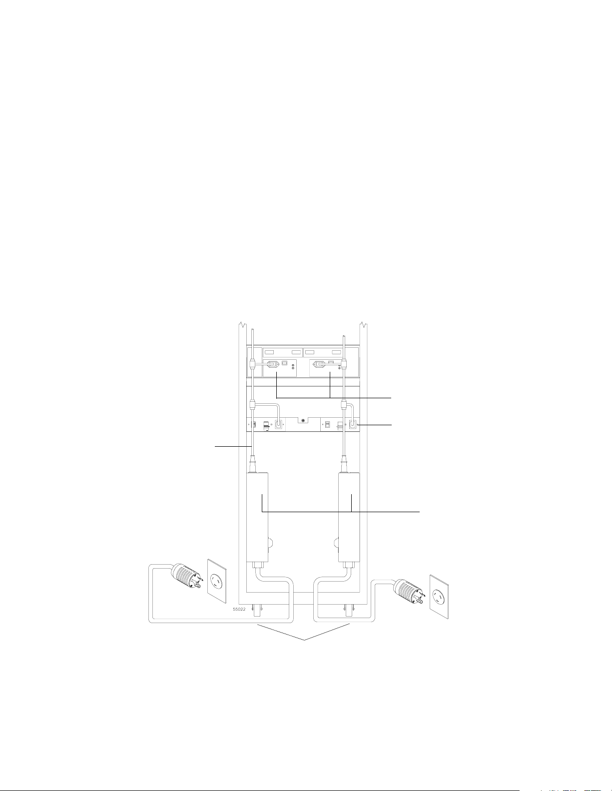
. . . . . . . . . . . . . . . . . . . . . . . . . . . . . . . . . . . . . . . . . . . . . . . . . . . . . . . . . . . . Power Requirements
Power Cord Routing
All modules are shipped with two AC power cords that are appropriate for use in a typical
outlet in the destination country. Each power cord connects one of the power supplies in a
module to an independent, external power source, such as a wall receptacle or
uninterruptible power supply (UPS). If you have a rackmount cabinet with internal power
cabling, such as a ladder cable, you do not need these power cords.
Typically, a rackmount cabinet has two AC distribution boxes with two separate power
cords (Figure 4-4). To ensure redundancy, each power cord must connect to an
independent, external power source. Each AC distribution box has a ladder cable that runs
up the inside of the cabinet and connects to one of the power supplies in each unit.
Figure 4-5 shows the power cords and receptacles for domestic (inside USA) and
international use (outside USA).
Ladder Cable
Array Module Power Supplies
Ladder Cable Connector
AC Power
Distribution Boxes
AC Power Distribution Box
Power Cords
Figure 4-4 Redundant AC Power Connections to Array Modules
Command Module and Drive Module Site Preparation Guide 4-9
Page 64

Array Module Site Preparation . . . . . . . . . . . . . . . . . . . . . . . . . . . . . . . . . . . . . . . . . . . . . . . . . . . . .
250 VAC, 16 A, IEC 320-C19 Cord
From AC Power
Distribution Box
Independent
External
Power S ource
250 VAC, 30 A, NEMA L6-30 Cord
(Domestic)
230 VAC, 32 A, IEC 309 Cord
(International)
Figure 4-5 Types of 72-Inch Cabinet AC Power Cords and Receptacles
4-10 Command Module and Drive Module Site Preparation Guide
Page 65

. . . . . . . . . . . . . . . . . . . . . . . . . . . . . . . . . . . . . . . . . . . . . . . . . . . . . . . . . . . . Power Requirements
Site Wiring
The array modules use wide-ranging, redundant power supplies that automatically
accommodate voltages to the AC power source. The power supplies operate at a range
between 90 VAC and 264 VAC, and at a minimum frequency of 50 Hz and a maximum
frequency of 60 Hz. The power supplies meet standard voltage requirements for both
domestic (inside USA) and international (outside USA) operation. They use standard
industrial wiring with line-to-neutral or line-to-line power connections.
Consider the following information when preparing the array module installation site.
Earth ground – The unit must be properly grounded, including an earth ground
•
conductor on the AC power source.
Circuit overloading – Ensure the power circuits and associated circuit breakers in the
•
cabinet and building provide sufficient power and overload protection. To prevent
possible damage to the unit, isolate its power source from large switching loads (such as
air conditioning motors, elevator motors, and factory loads).
Power interruptions – The array modules will withstand the following applied voltage
•
interruptions (with or without an integrated UPS):
Input transient – 50% of nominal voltage
•
Duration – one half cycle
•
Frequency – once every 10 seconds
•
Power failures – After a total power failure, the unit will automatically perform a
•
power-up recovery sequence without operator intervention once power is restored.
Command Module and Drive Module Site Preparation Guide 4-11
Page 66

Array Module Site Preparation . . . . . . . . . . . . . . . . . . . . . . . . . . . . . . . . . . . . . . . . . . . . . . . . . . . . .
Interface Cables and Connections
This section provides information about array module interface cables and their
appropriate connections.
The E2400 10x and E2400 14x array modules support Fibre Channel connections to drive
modules. Each module has four GBIC connectors; two on each controller. The connectors
may be fiber optic or copper (Figure 4-6). The connector type depends on what type of
drive interface you order and what type of cable you will be using to attach the array
module to the drive module.
Optical
Copper
Figure 4-6 Optical and Copper GBICs
4-12 Command Module and Drive Module Site Preparation Guide
Page 67

. . . . . . . . . . . . . . . . . . . . . . . . . . . . . . . . . . . . . . . . . . . . . . . . . . Interface Cables and Connections
If you order optical GBIC connectors, you will need fiber optic cable. If you order copper
GBIC minihubs, you will need copper fiber cable. Refer to Tabl e 4 -8 for types and cable
lengths available from your local dealer.
Table 4-8 E2400 10x and E2400 14x Array Module Fibre Channel Interface Cables
Descriptions Order Information
Cable Data Rate
Fiber optic
Multi-mode, 50 micrometer,
shortwave laser
Copper fiber
Shielded, twisted pair,
electrical signal
Transfer
Speed
Maximum
Range
100 MB/s 1062.5 Mb/s 0.5 kilometer
100 MB/s 1062.5 Mb/s 30 meters
Part
Number
Length
006-1086672 2 meter
006-1086416 3 meter
006-1086673 5 meter
006-1086417 10 meter
006-1086682 2 meter
006-1086672 3 meter
006-1086483 5 meter
006-1086473 10 meter
Command Module and Drive Module Site Preparation Guide 4-13
Page 68

Array Module Site Preparation . . . . . . . . . . . . . . . . . . . . . . . . . . . . . . . . . . . . . . . . . . . . . . . . . . . . .
4-14 Command Module and Drive Module Site Preparation Guide
Page 69

Index
A
array module
area requirements 4-2
dimensions 4-4
environmental requirements 4-7
heat dissipation 4-7
interface connections 4-12
power cord routing 4-9
power requirements 4-8
site wiring requirements 4-11
weight 4-2
C
cabinet
area requirements 1-4
dimensions 1-6
environmental requirements 1-7
features 1-2
ladder cords 1-10
power cords and receptacles 1-11
power requirements 1-8
site wiring requirements 1-12
weight 1-5
cable
copper fiber 2-13
fiber optic 2-13
command module
area requirements 2-2
dimensions 2-4
environmental requirements 2-6
interface connections 2-12
power cord routing 2-8
power requirements 2-8
site wiring requirements 2-11
weight 2-2
, 3-14, 4-13
, 2-14, 2-15, 3-14, 3-15, 4-13
D
data transfer rates 2-13, 3-14, 4-13
dimensions
array module 4-4
cabinet 1-6
command module 2-4
drive module 3-4
drive module
area requirements 3-2
dimensions 3-4
environmental requirements 3-7
heat dissipation 3-7
interface connections 3-13
power cord routing 3-9
power requirements 3-8
site wiring requirements 3-12
weight 3-2
E
environmental requirements
array module 4-7
cabinet 1-7
command module 2-6
drive module 3-7
E2400 10x
dimensions 4-4
environmental requirements 4-7
heat dissipation 4-7
interface connections 4-12
weight 4-2
E2400 14x
dimensions 4-5
environmental requirements 4-7
heat dissipation 4-7
interface connections 4-12
power requirements 4-8
weight 4-3
E4400
dimensions 2-4
environmental requirements 2-6
interface connections 2-12
power requirements 2-8
weight 2-2
Command Module and Drive Module Site Preparation Guide Index-1
Page 70

E4600
dimensions 2-4
environmental requirements 2-6
interface connections 2-14
power requirements 2-8
weight 2-3
E5600
dimensions 2-4
environmental requirements 2-6
interface connections 2-14
power requirements 2-8
weight 2-3
F
FC-1 10x
dimensions 3-4
environmental requirements 3-7
heat dissipation 3-7
interface connections 3-13
power requirements 3-8
weight 3-2
FC-1 14x
dimensions 3-5
environmental requirements 3-7
heat dissipation 3-7
interface connections 3-13
power requirements 3-8
weight 3-3
FC-2 14x
dimensions 3-5
environmental requirements 3-7
heat dissipation 3-7
interface connections 3-15
power requirements 3-9
weight 3-3
M
multi-mode cable 2-13, 3-14, 4-13
O
optical, fiber interface 2-13, 2-14, 3-14, 3-15,
4-13
P
power cord routing
array module 4-9
command module 2-8
drive module 3-9
power requirements
array module 4-8
cabinet 1-8
command module 2-8
drive module 3-8
S
shortwave laser 2-13, 3-14, 4-13
site wiring requirements
array module 4-11
cabinet 1-12
command module 2-11
drive module 3-12
U
uninterruptible power supply (UPS) 2-8, 3-9,
4-9
W
I
interface connections
array module 4-12
command module 2-12
drive module 3-13
weight
array module 4-2
cabinet 1-5
command module 2-2
drive module 3-2
L
ladder cords, cabinet 1-10
Index-2 Command Module and Drive Module Site Preparation Guide
 Loading...