

Page 1
MegaRAID®SAS 8344ELP
RAID Controller
Quick Installation Guide
Step 2 Prepare the Computer
Thank you for purchasing the MegaRAID®SAS (Serial
Attached SCSI/Serial ATA) 8344ELP (PCI Express low-profile)
RAID Controller. Please take a few minutes to read this quick
installation guide before you install the controller. If you need
more information about any topic covered in this guide, refer
to the related documents on your MegaRAID Universal
Software Suite CD.
Note: This is a PCI Express x4 card, so it fits only in a
PCI Express x4 or greater slot.
Note: SATA II is the only type of SATA supported by the
SAS 8344ELP Controller.
You can use the intelligent Battery Backup Unit 01
(LSIiBBU01) with the SAS 8344ELP. For more information
about this battery, refer to the MegaRAID Battery Backup Unit
User’s Guide on the MegaRAID Universal Software Suite CD.
MegaRAID SAS 8344ELP RAID CONTROLLER INSTALLATION
Make a backup of your data before you change
!
CAUTION
Step 1 Unpack the MegaRAID SAS 8344ELP RAID
your system configuration. Otherwise, you may
lose data.
Controller
Unpack the controller in a static-free environment.
Remove it from the antistatic bag and inspect it for
damage.
If the controller appears to be damaged, or if the
MegaRAID Universal Software Suite CD is
missing, contact LSI Logic or your MegaRAID
OEM support representative.
CAUTION
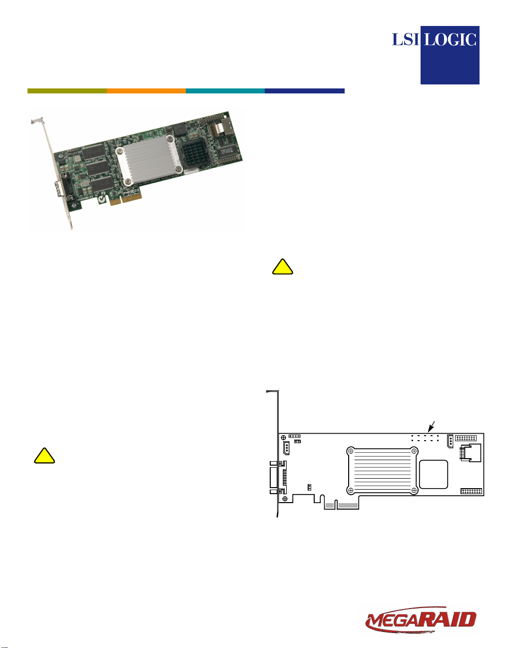
Step 3 Review the Jumpers and Connectors
Figure 1 MegaRAID SAS 8344ELP RAID Controller
The CD contains utility programs, device drivers
for various operating systems, and the following
documentation:
• MegaRAID SAS Storage Adapters User’s
Guide
• MegaRAID SAS Software User’s Guide
• MegaRAID SAS Device Driver Installation
User’s Guide
• Software license agreement
Turn off the computer and unplug the power
cord(s) from the back of the power supply. Remove
the cover from the computer.
Make sure the computer is disconnected from the
!
power and from any networks before installing
the controller.
Figure 1 shows the location of the jumpers and
connectors on the SAS 8344ELP. The jumpers are
set at the factory and you usually do not need to
change them.
Card Layout
J11
Connector Located
on Back of Board
J3
J4
J6
J1
J8
U12
P1
Note: J11, the battery backup connector, is located on
the back side of the SAS 8344ELP.
U15
J7
J10
®
J5
J9
Page 2
The following table describes the jumpers and
connectors on the SAS 8344ELP.
Jumper/
Connector Type Description
J1 SAS 8344ELP
J2 BIOS Disable
J3 Serial header for
J4 Mode Select
J5 Individual Activity
J6 IPMI-style SMBus
J7 IPMI-style
J8 Cache Write
J9 LED Drive
J10 SAS 8344ELP
J11 Battery Backup
Ports
header
debug use
header
LED header for all
eight ports
(System Manage-
2
C header
ment) /I
LSI1068 SMBUS
debug header
Pending LED
Fault Connector
Interface
Ports
Connector
(located on the
back side of the
controller)
Ports 0–3.
The ports connect the cables from
the adapter to SAS or SATA II physical drives, or a port multiplier.
2-pin header.
The BIOS function is enabled or dis-
abled in software depending on the
status of this jumper.
No jumper: BIOS is enabled (default).
Jumper: BIOS is disabled.
Note: The card does not function as
a RAID controller if this jumper is
mounted.
4-pin header.
Used for diagnostic purposes.
The serial port is not RS232 voltage
level compliant.
2-pin connector.
If thefirmwareflashed onto the board
is corrupted, you need to jumper J4
(this holds the CPU core in reset), so
you can flash the firmware. Remove
the jumper after you flash the new
firmware.
No jumper: This is the setting during
normal operation (Mode 3). This is
the default.
Jumper: This holds the CPU core in
reset (Mode 0).
Note: The card does not function as
a RAID controller if this jumper is
mounted.
16-pin (8x2) header.
Provides LEDinterface individually to
eight SATA II ports. The LED indicates activity on specific ports.
3-pin header.
Provides enclosure management
support.
3-pin header.
Used for diagnostic purposes.
2-pin connector.
Connector for enclosure LED.
Provides a signalthat indicates when
the on-board cache contains data
and a write from the cache to the
hard drives is pending. Optional.
16-pin (8x2) connector.
Provides LEDinterface individually to
eight SATA II ports. The LED indicates a drive fault on particular ports.
Ports 4–7.
The ports connect the cables from
the adapter to the SATA II physical
drives or port multiplier.
20-pin connector.
Provides interface to the remote bat-
tery pack.
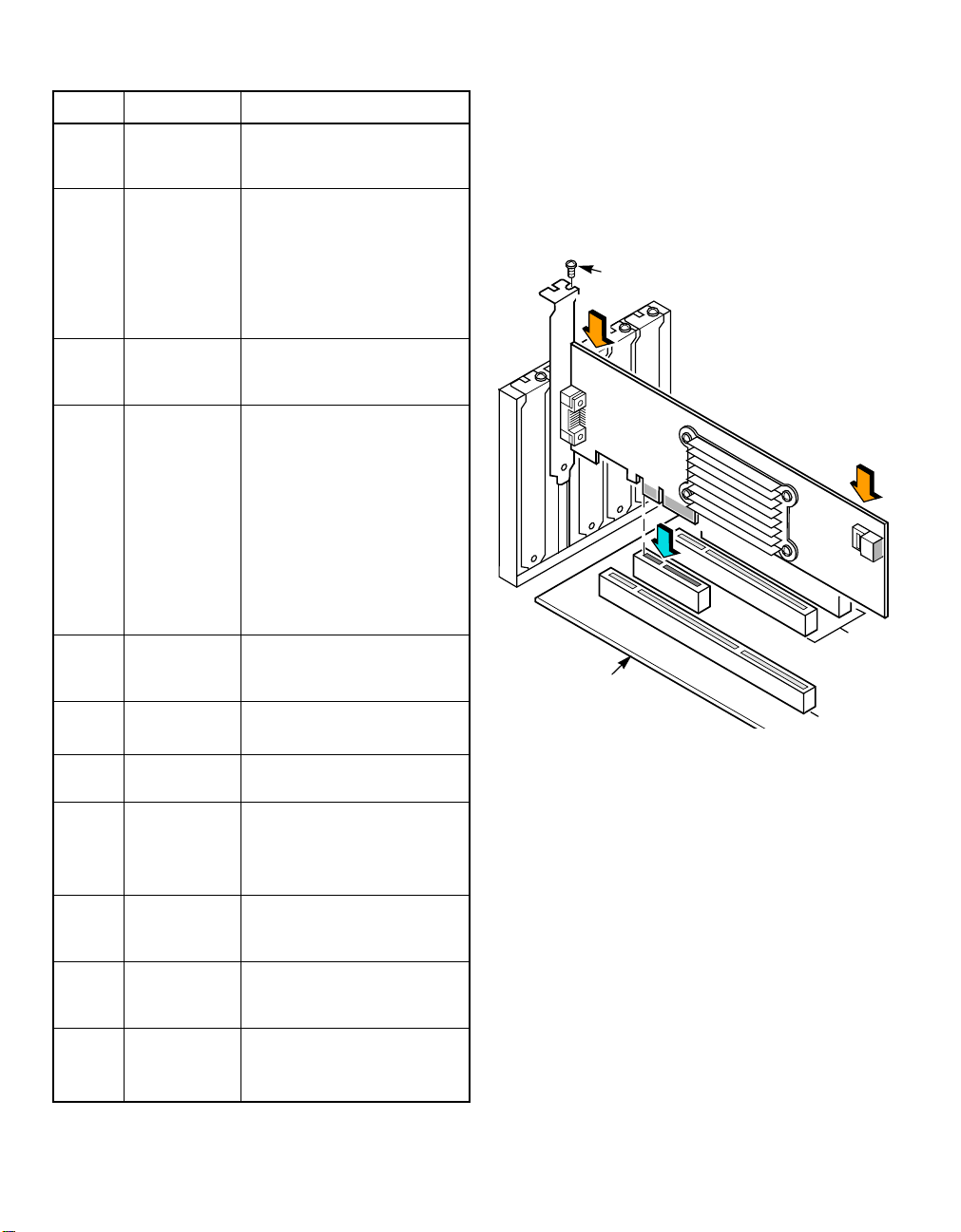
Step 4 Install the MegaRAID SAS 8344ELP RAID
Controller
Insert the SAS 8344ELP in a PCI-E slot on the
mainboard, as shown in Figure 2. Press down
gently but firmly to seat the card properly in the
slot. Secure the SAS 8344ELP to the computer
chassis with the bracket screw.
Figure 2 Installing the MegaRAID SAS 8344ELP
RAID Controller
Bracket Screw
Press Here
Press Here
32-bit Slots
(3.3 V)
Edge of
Main Board
64-bit Slots
(3.3 V)
Refer to your mainboard guide for information
about the PCI-E slot.
Step 5 Configure and Install SAS and/or SATA II
Devices
Configure the SAS and/or SATA II devices and
install them in the host system computer case.
Refer tothedocumentationfor the devices forany
pre-installation configuration requirements.
Step 6 Connect the MegaRAID SAS 8344ELP RAID
Controller to the SAS and/or SATA II Devices
Use SAS cables to connect the SAS 8344ELP to
SAS and/or SATA II devices. Refer to Figure 1 to
view connector locations on the controller.
Refer to the MegaRAID SAS Storage Adapters
User’s Guide on the MegaRAID Universal
Software Suite CD for detailed information about
the SAS cables.
2of3
Page 3

Step 7 Power-Up the Computer
Replace the computer cover and reconnect the
power cord(s). Turn on power to the computer.
Ensure that the devices are powered up before or
at the same time as the host computer. If the
computer is powered up before the devices, the
devices might not be recognized.
During boot, a MegaRAID BIOS message similar
to the following displays:
LSI LOGIC MEGARAID BIOS VERSION xxxx
[date]
Copyright (c) 2005, LSI Logic Corp.
HA-1 (Bus x Dev y) LSI MegaRAID SAS
8344ELP PCI-E
Standard FW xxxx DRAM=xxx MB(SDRAM)
The firmware takes several seconds to initialize.
During this time the adapter scans the Serial ATA
ports.
Step 8 Run the WebBIOS Configuration Utility
Run the WebBIOS Configuration Utility to
configure the physical arrays and logical drives.
When the message Press <Ctrl><H> for
WebBIOS displays on the screen, press CTRL+H
immediately to run the utility.
Note: Refer to the MegaRAID SAS Software User’s
Guide on the MegaRAID Universal Software
Suite CD for detailed steps on configuring
physical arrays and logical drives.
Step 9 Install the Operating System Driver
The SAS 8344ELP can operate under various
operating systems. To operate under these
operating systems, you must install software
drivers.
The MegaRAID Universal Software Suite CD
includes drivers for the supported operating
systems, along with documentation. You can view
the supported operating systems and download
the latest drivers for RAID adapters on the
LSI Logic web site at:
http://www.lsilogic.com/downloads/main.do.
Access the download center and follow the steps
to download the driver.
Refer to the MegaRAID SAS Device Driver
Installation User’s Guide on the MegaRAID
Universal Software Suite CD for details on
installing the driver. Be sure to use the latest
Service Packs provided by the operating system
manufacturer and review the readme file that
accompanies the driver.
SUPPORTED RAID LEVELS
The SAS 8344ELP supports disk arrays using the following
RAID levels:
• RAID 0 (Data striping): Data is striped across all disks
in the array, enabling very fast data throughput. There is
no data redundancy. All data is lost if any disk fails.
• RAID 1 (Disk mirroring): Data is written simultaneously
to two disks, providing complete data redundancy if one
disk fails. The maximum array capacity is equal to the
available size of the smaller of the two hard drives.
• RAID 5 (Disk striping with distributed parity): Data is
striped across all disks in the array. Part of the capacity
of each disk stores parity information that reconstructs
data if a disk fails. Provides good data throughput for
applications with high read request rates.
• RAID 10 (RAID 1 and RAID 0 in spanned arrays): Uses
mirrored pairs of disks to provide complete data
redundancy. Provides high data throughput rates.
• RAID 50 (RAID 5 and RAID 0 in spanned arrays): Uses
both parity and disk striping across multiple disks to
provide complete data redundancy. Provides high data
throughput rates.
TECHNICAL SUPPORT
For assistance installing, configuring, or running the SAS
8344ELP, contact LSI Technical Support:
E-mail:
support@lsil.com
eurosupport@lsil.com (Europe)
Phone Support:
1-800-633-4545 (North America)
+44 1344 413 441 (Europe)
Web Site:
http://www.lsilogic.com/support/
®
PN: 80-00112-01 Rev. A
DB11-000072-01, Version 2.0, February 2006
Find a list of LSI Logic Corporation’s U.S. distributors, international distributors,
sales offices, and design resource centers on the LSI Logic web site at:
http://www.lsilogic.com/contacts/index.html
LSI Logic,the LSI Logic logo design, and MegaRAID are registered trademarksof
LSI Logic Corporation. All other brand and product names may be trademarks of
their respective companies.
Copyright © 2005-2006 by LSI Logic Corporation. All rights reserved.
LSI Logic products are not intended for use in life-support appliances, devices, or
systems. Use of any LSILogic productin suchapplications without written consent
of the appropriate LSI Logic officer is prohibited.
Purchase of I
Associated Companies, conveys a license under the Philips I
use these components inan I
2
C standard Specification as defined by Philips.
I
LSI Logic Corporation reserves the right to make changes to any products and
services herein at any time without notice. LSI Logic does not assume any
responsibility or liability arising out of the application or use of any product or
service described herein, except as expressly agreed to in writing by LSI Logic;
nor does the purchase, lease, or use of a product or servicefrom LSI Logic convey
a license under any patent rights, copyrights, trademark rights, or any other of the
intellectual property rights of LSI Logic or of third parties.
2
C components of LSI Logic Corporation, or one of its sublicensed
2
C system, provided thatthe system conforms to the
2
C Patent Rights to
 Loading...