

Page 1

USER’S
GUIDE
LSI7202CP CompactPCI
Dual Channel
2 Gbit/s Fibre Channel
Host Adapter
February 2002
Version 1.0
®
DB15-000228-00
Page 2
Electromagnetic Compatibility Notices
This equipment has been tested and found to comply with the limits for a Class A digital device, pursuant to Part
15 of the FCC Rules. These limits are designed to provide reasonable protection against harmful interference in a
commercial installation. This equipment generates, uses, and can radiate radio frequency energy and, if not installed
and used in accordance with the instructions, may cause harmful interference to radio communications. Operation
of this equipment in a residential area is likely to cause harmful interference, in which case the user will be required
to correct the interference at his own expense.
LSI Logic Corporation is not responsible for any radio or television interference caused by unauthorized modification
of this equipment or the substitution or attachment of connecting cables and equipment other than those specified
by LSI Logic Corporation. It is the user’s responsibility to correct interference caused by such unauthorized
modification, substitution, or attachment.
This Class A digital apparatus meets all requirements of the Canadian Interference-Causing Equipment Regulations.
Cet appareil numérique de la classé A respecte toutes les exigences du Règlement sure le matèriel brouilleur du
Canada.
LSI Logic Corporation
North American Headquarters
Milpitas, CA
408.433.8000
ii
Copyright © 2001, 2002 by LSI Logic Corporation. All rights reserved.
Page 3

This document contains proprietary information of LSI Logic Corporation. The
information contained herein is not to be used by or disclosed to third parties
without the express written permission of an officer of LSI Logic Corporation.
LSI Logic products are not intended for use in life-support appliances, devices,
or systems. Use of any LSI Logic product in such applications without written
consent of the appropriate LSI Logic officer is prohibited.
The host adapter(s) referred to in this User's Guide contain one or more
transceivers that are certified as Class 1 laser products that conform to the
requirements contained in the US Food and Drug Administration - Center for
Devices and Radiological Health (FDA/CDRH) regulation 21 CFR 1040,
Performance Standards for Light-Emitting Products and 21 CFR 1010,
Performance Standards for Electronic Products: General.
Internationally, these transceivers are certified as Class 1 laser products that
conform to the requirements contained in the International Electrotechnical
Commission (IEC) standard 825-1 (1993). Class 1 laser products are not
considered to be hazardous based upon current medical knowledge. This class
includes all lasers or laser systems which cannot emit levels of optical radiation
above the exposure limits for the eye under any exposure conditions inherent in
the design of the laser product. The design of the transceivers on this host
adapter is such that access to laser radiation above a Class 1 emission level
during operation, user maintenance, or service conditions is prevented. However,
there may be a laser embedded in the enclosure of the Class 1 laser that is more
hazardous, but harmful radiation cannot escape the intact enclosure. With any
laser,the following precautions should be followed to prevent accidental exposure
to any levels of optical radiation.
CAUTION: Do not look into the transceiver ports, do not view the transceiver
ports with optical instruments, and avoid direct exposure to the beam.
The following certification information is permanently affixed to or inscribed on
the transceiver product so as to be legible and readily accessible to view when
the transceiver is fully assembled for use.
• Laser Manufacturer
• Model #
• Serial #
Copyright © 2001, 2002 by LSI Logic Corporation. All rights reserved.
iii
Page 4

Document DB15-000228-00, Second Printing (February 2002). This document
describes the LSI Logic LSI7202CP CompactPCI Dual Channel 2 Gbit/s Fibre
Channel Host Adapter and will remain the official reference source for all
revisions/releases of this product until rescinded by an update.
LSI Logic Corporation reserves the right to make changes to any products herein
at any time without notice. LSI Logic does not assume any responsibility or
liability arising out of the application or use of any product described herein,
except as expressly agreed to in writing by LSI Logic; nor does the purchase or
use of a product from LSI Logic convey a license under any patent rights,
copyrights, trademark rights, or any other of the intellectual property rights of
LSI Logic or third parties.
Copyright © 2001, 2002 by LSI Logic Corporation. All rights reserved.
TRADEMARK ACKNOWLEDGMENT
The LSI Logic logo design and Fusion-MPT are registered trademarks of LSI
Logic Corporation. Solaris and the Solaris logo are trademarks or registered
trademarks of Sun Microsystems, Inc. in the US and other countries and are
used under license. All other brand and product names may be trademarks of
their respective companies.
To receive product literature, visit us at http://www.lsilogic.com.
For a current list of our distributors, sales offices, and design resource
centers, view our web page located at
http://www.lsilogic.com/contacts/na_salesoffices.html
iv
Copyright © 2001, 2002 by LSI Logic Corporation. All rights reserved.
Page 5

Audience
Preface
This book is the user’s guide for the LSI Logic LSI7202CP CompactPCI
Dual Channel 2 Gbit/s Fibre Channel Host Adapter. It includes
instructions for installing this adapter with regard to cold and hot
installations and provides this adapter’s specifications.
This document assumes that you have some familiarity with CompactPCI
computers and related support devices. The people who benefit from this
book are:
• Engineers and managers who are evaluating or designing the host
adapter board for possible use in a system
• End users who are installing the host adapter board into their
computer
Organization
This document has the following sections:
• Chapter 1, Installing/Extracting the LSI7202CP Host Adapter
• Chapter 2, LSI7202CP Host Adapter Characteristics
• Chapter 3, BIOS Features
• Chapter 4, Solaris Software Requirements
• Appendix A, Glossary of Terms and Abbreviations
LSI7202CP CompactPCI Dual Channel 2 Gbit/s Fibre Channel Host Adapter v
Copyright © 2001, 2002 by LSI Logic Corporation. All rights reserved.
Page 6

Conventions Used in This Manual
Notation Example Meaning and Use
courier typeface # cfagdm Names of commands and the output from the commands
are shown in courier type face and enclosed in a box.
italic underscore attachment_point When an underscore appears in an italicized string next
to a command, enter a user-supplied item of the type
called for with no spaces.
Revision Record
Revision Date Remarks
0.5 11/01 First release.
0.6 12/01 Second Advance printing. Front matter includes laser safety statement.
1.0 02/02 Final printing. Converted to LSI Logic format. Changes throughout.
Added Section 8.
vi Preface
Copyright © 2001, 2002 by LSI Logic Corporation. All rights reserved.
Page 7

Contents
Chapter 1 Installing/Extracting the LSI7202CP Host Adapter
1.1 Host Adapter Installation 1-1
1.1.1 Cold Installation Preparation 1-1
1.1.2 Hot Installation Preparation 1-2
1.1.3 Installation 1-2
1.2 Extracting the LSI7202CP 1-3
1.2.1 Cold Environment Extraction 1-3
1.2.2 Hot Environment Extraction 1-3
Chapter 2 LSI7202CP Host Adapter Characteristics
2.1 General Description 2-1
2.1.1 Features 2-1
2.1.2 Hardware and Software Support 2-1
2.1.3 Fibre Channel Cable Assemblies 2-2
2.2 Technical Characteristics 2-3
2.2.1 Bus Interfaces 2-3
2.2.2 Technical Specifications 2-5
Chapter 3 BIOS Features
3.1 BIOS Features 3-1
3.1.1 Intel BIOS 3-1
3.1.2 Starting the Intel BIOS Configuration Utility 3-2
3.1.3 Using the Intel BIOS Configuration Utility 3-3
3.1.4 Exiting the Intel BIOS Configuration Utility 3-5
3.1.5 Fcode 3-6
3.2 Troubleshooting 3-14
LSI7202CP CompactPCI Dual Channel 2 Gbit/s Fibre Channel Host Adapter vii
Copyright © 2001, 2002 by LSI Logic Corporation. All rights reserved.
Page 8

Chapter 4 Solaris Software Requirements
4.1 Device Driver Software Requirements 4-1
4.2 Verifying the Installation 4-1
4.2.1 nonvolatileMethod 1 –
Using the show-devs Command 4-2
4.2.2 Method 2 Using the probe-scsi-all Command 4-3
4.3 itmpt Device Driver 4-4
4.3.1 Installing the itmpt Sun SPARC Solaris Driver 4-4
Appendix A Glossary of Terms and Abbreviations
Index
Customer Feedback
Figures
2.1 LSI7202CP CompactPCI Host Adapter 2-3
4.1 pkgadd Procedure 4-5
4.2 Completing Floppy Disk Installation 4-6
Tables
2.1 Hardware and Software Requirements 2-2
2.2 Specifications 2-5
2.3 Power Requirements 2-5
4.1 Error Messages 4-10
viii Contents
Copyright © 2001, 2002 by LSI Logic Corporation. All rights reserved.
Page 9

Chapter 1
Installing/Extracting the
LSI7202CP Host Adapter
This chapter describes the installation procedures for the LSI7202CP
CompactPCI Dual Channel 2 Gbit/s Fibre Channel host adapter. The
main topics are:
• Section 1.1, “Host Adapter Installation,” page 1-1
• Section 1.2, “Extracting the LSI7202CP,” page 1-3
1.1 Host Adapter Installation
This section provides a general overview of the tasks needed to perform
either a hot or cold installation. For the exact procedures required for
your system, refer to the operating system and system documentation.
1.1.1 Cold Installation Preparation
Before shutting down the operating environment and halting the system,
ensure that all significant application activity on the server has stopped.
To prepare the system for a cold installation, follow these steps.
Step 1. Follow the appropriate procedures, as documented in the
system’s service manual, to shut down and halt the system.
Step 2. Refer to the system’s documentation for the complete power
down procedure and location of the power switch.
Step 3. Press the power switch on the system’s status panel to power
down the system.
Step 4. Verify that the system’s power LED is OFF, which indicates that
the system is completely powered off.
After the system has been shut down and powered off, you can
safely install the card.
LSI7202CP Compact PCI Dual Channel 2 Gbit/s Fibre Channel Host Adapter 1-1
Copyright © 2001, 2002 by LSI Logic Corporation. All rights reserved.
Page 10

1.1.2 Hot Installation Preparation
Refer to your system’s hardware user’s manual for complete instructions
regarding hot installation.
1.1.3 Installation
Review your system’s documentation for the complete instructions before
performing the following steps to install the LSI7202CP into your system:
Step 1. Identify the slot number where you want to insert the adapter.
Step 2. Refer to the system’s documentation for instructions on how to
remove the filler panel.
Step 3. Remove the filler panel from the slot you selected.
Step 4. Push on the red release button and open the LSI7202CP card’s
ejection lever before installing the card in the system.
Step 5. Pull back the ejection lever and slide the card into the
CompactPCI slot.
Step 6. Apply even pressure at both corners of the card and push the
card until it is firmly seated in the slot.
Step 7. Push the ejection lever over the sprocket toward the card and
into the locked position. This locks the card into the slot.
Step 8. Use a Phillips screwdriver to tighten the captive screws inside
the card’s ejection lever.
Step 9. Attach the Fibre Channel cable to either Port 0 or Port 1 of the
LSI7202CP. This completes the hardware installation.
Important: Check your system’s documentation for any additional
actions that may be required to configure the system software for the newly inserted card.
1-2 Installing/Extracting the LSI7202CP Host Adapter
Copyright © 2001, 2002 by LSI Logic Corporation. All rights reserved.
Page 11

1.2 Extracting the LSI7202CP
The LSI7202CP is a component that you can extract from a hot-swap
compliant system without interrupting the operation of the system. You
can also extract the adapter if installing it in a cold environment after you
power down the system.
You must determine whether you want to perform a cold extraction of the
adapter or a hot extraction. In a cold extraction, you must shut down the
system’s operating system and power down the system before extracting
the adapter. In a hot-swap extraction, you may be required to enter
software commands before and after the extraction to detach the adapter
from the system correctly.
Note : The following procedures provide a general overview of the
tasks needed to prepare for either a hot or cold extraction.
For the specific procedures required for your system, refer
to the documentation that shipped with your system.
1.2.1 Cold Environment Extraction
Before extracting your adapter, ensure that all significant application
activity on the server has stopped. To extract the LSI7202CP, follow
these steps.
Step 1. Refer to the system’s documentation for the complete power
down procedure and location of the power switch.
Step 2. Press the power switch to power down the system.
Step 3. Verify that the system’s power LED is OFF, which indicates that
the system is completely powered off.
Step 4. Extract the LSI7202CP after the system has been shut down
and powered off.
1.2.2 Hot Environment Extraction
Refer to your system’s hardware user’s manual for complete instructions
regarding hot environment extraction.
Extracting the LSI7202CP 1-3
Copyright © 2001, 2002 by LSI Logic Corporation. All rights reserved.
Page 12

1-4 Installing/Extracting the LSI7202CP Host Adapter
Copyright © 2001, 2002 by LSI Logic Corporation. All rights reserved.
Page 13

Chapter 2
LSI7202CP
Host Adapter
Characteristics
This chapter provides instructions for installing and extracting the host
adapter board and includes these topics:
• Section 2.1, “General Description,” page 2-1
• Section 2.2, “Technical Characteristics,” page 2-3
2.1 General Description
The LSI7202CP is a CompactPCI dual channel 2 Gbit/s Fibre Channel
host adapter. The following sections describe the features of and the
hardware and software support for the LSI7202CP.
2.1.1 Features
The LSI7202CP adapter supports these features:
• Hot-swap CompactPCI/PCI installation and removal
• Asynchronous and synchronous transfers
2.1.2 Hardware and Software Support
The LSI7202CP supports most major software operating systems, such
as Sun Solaris (2.6 and higher), Windows Server (NT 4.0, 2000, XP,
.NET), Linux (RedHat, Suse, Caldera, Turbo), NetWare, UnixWare, HPUX, and OS/2. The LSI7202CP host adapter utilizes the Fusion-MPT
architecture for all major operating systems. Fusion-MPT architecture
offers the unique feature of having a single, binary operating system
driver that supports Fibre Channel devices and other bus architectures.
LSI7202CP CompactPCI Dual Channel 2 Gbit/s Fibre Channel Host Adapter 2-1
Copyright © 2001, 2002 by LSI Logic Corporation. All rights reserved.
™
Page 14

Before you use the LSI7202CP, make sure your system meets the
specific hardware and software requirements as shown in Table 2.1.
Table 2.1 Hardware and Software Requirements
Component Requirements
For Solaris SPARC hardware environments
Hardware Any Sun Microsystems computer with an avail-
Software The Solaris 8 operating environment
Firmware OpenBoot PROM, version 2.1 or greater
For Intel IA-32 or IA-64 hardware environments
Hardware Any Intel compatible
Software Windows Server (NT 4.0, 2000, XP, .NET)
Firmware Any Intel compatible BIOS system
able CompactPCI slot
Linux (RedHat, Suse, Caldera, Turbo)
NetWare, UnixWare, HP-UX, and OS/2
2.1.3 Fibre Channel Cable Assemblies
You will use one of two types of Fibre Channel cable assemblies based
on your system.
• LSI7202CP-LC and LSI7202CP-LC6
– LC optical to LC optical
– LC optical to SC optical
• LSI7202CP-HS and LSI7202CP-HS6
– HSSDC2 to HSSDC2
– HSSDC2 to HSSDC
2-2 LSI7202CP Host Adapter Characteristics
Copyright © 2001, 2002 by LSI Logic Corporation. All rights reserved.
Page 15
2.2 Technical Characteristics
This section provides information about the CompactPCI, PCI, and Fibre
Channel interfaces on the LSI7202CP. It also includes information about
the physical, electrical, and the thermal/atmospheric characteristics of
the LSI7202CP.
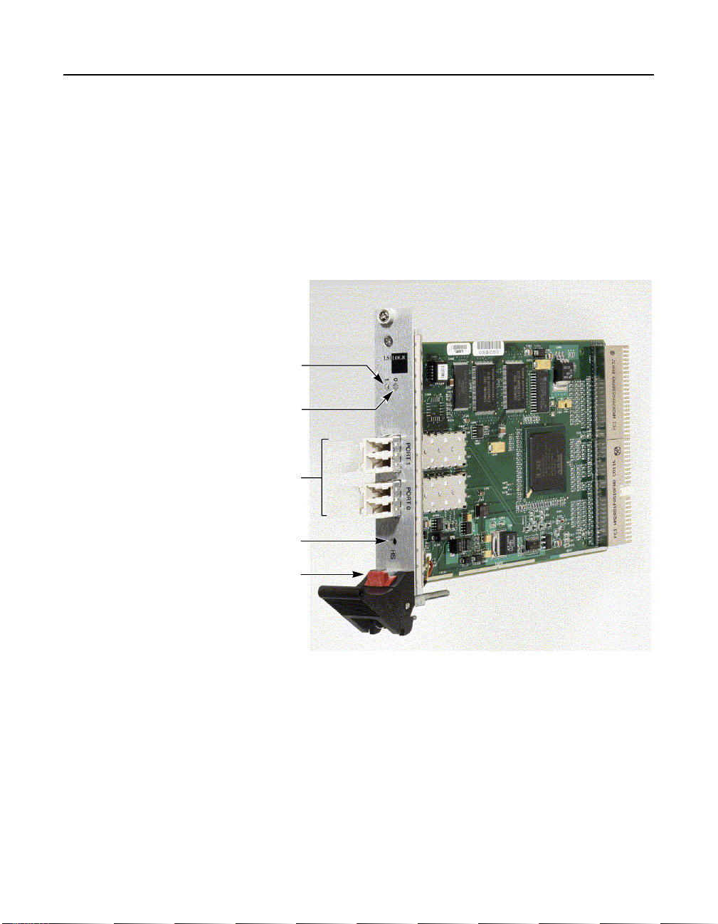
Figure 2.1 provides a photo of the LSI7202CP.
Figure 2.1 LSI7202CP CompactPCI Host Adapter
Port 1 LED
Port 0 LED
Port 0 and Port 1
External Fibre
Channel Connectors
Hot-Swap LED
Red Release Button
and Ejection Lever
2.2.1 Bus Interfaces
This section describes the bus interfaces that the LSI7202CP supports.
2.2.1.1 CompactPCI Interface
CompactPCI is an adaptation of the Peripheral Component interconnect
(PCI) Specification for industrial and/or embedded applications that
Technical Characteristics 2-3
Copyright © 2001, 2002 by LSI Logic Corporation. All rights reserved.
Page 16

require a more robust mechanical form factor than desktop PCI.
CompactPCI is electrically compatible with the PCI Specification,
allowing low cost PCI components to be utilized in a mechanical form
factor suited for more rugged environments. The LSI7202CP fully
supports Hot Swap as defined in the CompactPCI Hot Swap
Specification, Revision 1.0.
2.2.1.2 PCI Interface
The PCI functionality for the LSI7202CP is contained within the
LSIFC929 Dual Channel Fibre Channel I/O Controller. This controller
connects directly to the PCI bus and generates timing and protocol in
compliance with PCI specifications. This interface provides a high-speed,
standard local bus to the processor and memory subsystems in your
computer.
2.2.1.3 Fibre Channel Interface
The Fibre Channel interface for the LSI7202CP is also contained within
the LSIFC929 Dual Channel Fibre Channel I/O Controller.The LSIFC929
controller provides a direct interface to Fibre Channel. This controller
generates timing and protocol in compliance with the Fibre Channel
standard.
2-4 LSI7202CP Host Adapter Characteristics
Copyright © 2001, 2002 by LSI Logic Corporation. All rights reserved.
Page 17

2.2.2 Technical Specifications
This section contains the technical specifications for the LSI7202CP.
2.2.2.1 Data Transfer Specifications
Table 2.2 lists the performance specifications for the LSI7202CP.
Table 2.2 Specifications
Feature Specification
cPCI clock 66 MHz max
cPCI data burst transfer rate 264 Mbytes/s
2.2.2.2 Physical Characteristics
The LSI7202CP fits the 3U Eurocard form factor of 160.00 mm x
100.00 mm, as defined in the CompactPCI Specification, Revision 3.0.
The component height on the top and bottom of the LSI7202CP follows
Revision 3.0 of the CompactPCI Specification, Revision 2.2 of the PCI
Local Bus Specification.
2.2.2.3 Electrical Characteristics
Table 2.3 provides the power requirements for the LSI7202CP.
Table 2.3 Power Requirements
Operating Voltage Power
3.3 V ± 5% Operation 50.0 mW
5.0 V ± 5% Operation 7.75 W
Technical Characteristics 2-5
Copyright © 2001, 2002 by LSI Logic Corporation. All rights reserved.
Page 18

2.2.2.4 Thermal and Atmospheric Characteristics
The following parameters define the thermal and atmospheric
environment for the LSI7202CP during normal operation:
• Temperature range: 0 °Cto55°C (dry bulb)
• Relative humidity range: 5% to 90% noncondensing
• Maximum dew point temperature: 32 °C
• Airflow must be sufficient to keep the LSIFC929 heat sink
temperature below 65 °C
The following parameters define the storage and transit environment for
the LSI7202CP:
• Temperature range: −40 °C to +105 °C (dry bulb)
• Relative humidity range: 5% to 90% noncondensing
2.2.2.5 Electromagnetic Compliance
The design of the LSI7202CP minimizes electromagnetic emissions,
susceptibility to radio frequency energy, and the effects of electrostatic
discharge. The LSI7202CP carries the BSMI, CE mark, FCC SelfCertification log, Canadian Compliance Statement, VCCI, and meets the
requirements of FCC Class A.
2.2.2.6 Safety Characteristics
The LSI7202CP meets or exceeds the requirements of Underwriters
Laboratory (UL) flammability rating 94 V0. The LSI7202CP is also
marked with the supplier’s name or trademark, type, and UL flammability
rating.
2-6 LSI7202CP Host Adapter Characteristics
Copyright © 2001, 2002 by LSI Logic Corporation. All rights reserved.
Page 19

Chapter 3
BIOS Features
This chapter provides information pertaining to Intel BIOS and Solaris
Fcode and includes these topics:
• Section 3.1, “BIOS Features,” page 3-1
• Section 3.2, “Troubleshooting,” page 3-14
3.1 BIOS Features
A BIOS is the ROM code that is loaded by the system to facilitate booting
from Fibre Channel drives. The BIOS also contains an embedded
configuration manager, used to configure options provided by the
firmware. The LSI Logic BIOS integrates with a standard system BIOS,
extending the standard disk service routine provided through INT13h.
Two types of BIOS are available for the LSI7202CP:
• Intel BIOS for Intel-based platforms
• Fcode for Solaris SPARC platforms.
Both Intel BIOS and Fcode concurrently reside on the boards.
3.1.1 Intel BIOS
This section provides the features, description, and installation of the
Intel Fibre Channel BIOS.
3.1.1.1 Intel BIOS Features
The LSI Logic FC Intel BIOS features support:
• Selection and configuration for up to 256 adapters
LSI7202CP CompactPCI Dual Channel 2 Gbit/s Fibre Channel Host Adapter 3-1
Copyright © 2001, 2002 by LSI Logic Corporation. All rights reserved.
Page 20

• Boot device selection from any four host adapters
• Automatic INT13 drive mapping for Fibre Channel drives
3.1.1.2 BIOS Overview
During the boot time initialization, the Intel BIOS determines if there are
other hard disks, such as an IDE drive, already installed by the system
BIOS. If there are, the Intel BIOS maps any Intel drives it finds after the
drive(s) already installed. Otherwise, the Intel BIOS installs drives
starting with the system boot drive. In this case, the system boots from
a drive controlled by the Intel BIOS.
3.1.1.3 Intel BIOS Boot Specification (BBS)
The Intel BIOS provides support for the BIOS Boot Specification (BBS),
which allows you to choose which device to boot from by selecting the
priority.
To use this feature, the system BIOS must also be compatible with the
BBS. If your system supports the BBS, use the system BIOS setup menu
to select the boot and drive order. In the system BIOS setup, the Boot
Connection Devices menu appears with a list of available boot options.
Use that menu to select the device and rearrange the order. Then exit to
continue the boot process.
3.1.2 Starting the Intel BIOS Configuration Utility
The LSI Logic Intel BIOS allows you to change the default configuration
of your host adapters, using the embedded BIOS Configuration Utility.
When the BIOS loads, the following message appears on your monitor:
Press Ctrl-C to start LSI Logic Configuration Utility...
This message remains on your screen for about five seconds, giving you
time to start the utility. After you press Ctrl-C, the message changes to:
Please wait, invoking LSI Logic Configuration Utility...
After a brief pause, your computer monitor displays the Main menu of the
BIOS Configuration Utility.
3-2 BIOS Features
Copyright © 2001, 2002 by LSI Logic Corporation. All rights reserved.
Page 21

Note: Not all devices detected by the Configuration Utility can be
controlled by the BIOS. Devices such as tape drives and
scanners require that a device driver specific to that peripheral be loaded. The BIOS Configuration Utility does allow
parameters to be modified for these devices.
3.1.3 Using the Intel BIOS Configuration Utility
This section provides the menu formats and user inputs available to
inform users about this utility prior to running it. All BIOS Configuration
Utility screens that display various menus are partitioned into fixed areas.
This area provides static general help text information.
3.1.3.1 Main Menu
When you invoke the LSI Logic Intel BIOS Configuration Utility, the Main
menu appears. This screen displays a scrolling list of up to 256 host
adapters in the system and information about each of them.
To select an adapter, use only the arrow keys and enter key. Then, press
Enter to view and modify the selected adapter’s properties (and to gain
access to the attached devices). After selecting an adapter and pressing
Enter, the FC Link bus is scanned and the Adapter Properties screen
appears.
On the Main menu, two selections are the Boot Adapter List and Global
Properties menus.
Boot Adapter List allows selection and ordering of boot adapters. Refer
to Section 3.1.3.5, “Boot Adapter List Menu,” page 3-5 for more detailed
information.
Global Properties allows changes to global scope settings. Refer to
Section 3.1.3.6, “Global Properties Menu,” page 3-5 for more detailed
information.
Only adapters with LSI Logic Control enabled can be accessed.
3.1.3.2 Adapter Properties Menu
The Adapter Properties menu allows you to view and modify adapter
settings. It also provides access to an adapter's device settings. To
BIOS Features 3-3
Copyright © 2001, 2002 by LSI Logic Corporation. All rights reserved.
Page 22

display this menu, select a device under Adapter field on the Main menu
and press Enter.
3.1.3.3 Persistent IDs Menu
The Persistent ID screen is used to review the automatic mapping
between a drive WorldWide Name and its assigned logical SCSI bus and
target ID. You can also use this screen to force a drive to a specific
logical Target ID.
Selecting Add WWN at an unused location clears out the associated
WWN/DID field and allows you to enter the first 16 characters of the
WWN. Pressing <Enter> afterwards allows the last 16 characters to be
entered. The CU automatically adds any leading zeros if necessary. If
you make an entry by mistake, select Erase on the appropriate line to
remove the entry.
Logical ID selection defaults to be the lowest ID available. This can be
changed by using the <+> or <-> keys to cycle the numbers. The Bus
field always defaults to 0 and cannot be changed. It is displayed in the
case where an outside utility reserved a different number.
Next Page and Previous Page options are provided on the persistent ID
screens, through the F2 key, which moves the screen forward or back by
16 entries. However, the CU requires that any modifications to the
current page be stored before new entries may be viewed or modified. A
confirmation window pops up asking to store or discard changes if
needed.
3.1.3.4 Device Properties Menu
The Device Properties menu allows you to view and update individual
device settings for an adapter.
Note: The number of fields on the menu requires that you scroll
3-4 BIOS Features
left/right to view all of the information. When accessing this
menu, use the Home/End keys to scroll to columns currently not displayed. The scroll indicator on the bottom of
the menu shows where the cursor is relative to the first and
last columns.
Copyright © 2001, 2002 by LSI Logic Corporation. All rights reserved.
Page 23

3.1.3.5 Boot Adapter List Menu
The Boot Adapter List menu specifies the order in which adapters boot
when more than one LSI Logic host adapter is in a system. You can
select up to four of the total adapters in a system as bootable; however,
you can use only one of the four “active” adapters to control a Boot
Volume.
To select this menu:
1. Press F2 while on the Main menu to move the cursor to the menu
area.
2. Move the cursor to Boot Adapter List with the arrow keys.
3. Press Enter .
You can add or delete adapters using this menu. To add an adapter to
the boot list, press the Insert key while on the Boot Adapter List. Use
the arrow keys to select the desired adapter and press Enter to add it
to the end of the Boot Adapter List.
To remove an adapter from the boot list, press the Delete key while on
the desired adapter in the Boot Adapter List. You can also change the
boot order by using the “+” or “−” keys. For example, place the cursor on
the adapter that you want to change, and use the “+” or “−” key to raise
or lower the boot order.
3.1.3.6 Global Properties Menu
The Global Properties menu allows you to pause if an alert message has
been displayed, to view display boot information, and to set display and
video modes.
3.1.4 Exiting the Intel BIOS Configuration Utility
The Exit menu for the Intel BIOS Configuration Utility is used for all five
of the menus listed above. However, the available functionality is different
for the Main menu and the four subordinate menus.
BIOS Features 3-5
Copyright © 2001, 2002 by LSI Logic Corporation. All rights reserved.
Page 24

To exit from the Adapter Properties, Device Properties, Boot Adapter List,
or Global Properties menus, use these exit options:
Cancel exit This option returns you to the previous menu.
Save changes then
exit this menu
Discard changes
then exit this menu
To exit from the Main menu, use these exit options:
Cancel exit This returns you to the Main menu.
Exit the Configuration
Utility
Important: If you reboot the system without properly exiting from this
3.1.5 Fcode
LSI Logic Solaris-capable Fusion-MPT host adapters have Fcode
resident on board, allowing operation under Sun’s openboot console. All
basic functionality is available at openboot, including the ability to display
devices connected to the adapter, and boot devices on the adapter.
3.1.5.1 Fcode Features
This option implements any changes you made on the
previous menu and returns you to the Main menu.
This option restores the default settings and returns
you to the Main menu.
This option exits the configuration and automatically
reboots your system.
utility, some changes may not take effect.
The LSI Logic FC Fcode features support for:
• Solaris Sparc 2.6, 2.7, and Solaris 8 Open Firmware environments
• Root Boot device selection from any target device
• Standard command line interface, with help query
• Configuration options and selection for each host adapter
3.1.5.2 Identifying the Fibre Channel Disks
The probe-scsi-all command is used to identify the Fibre Channel
devices on the Fusion-MPT adapter.
3-6 BIOS Features
Copyright © 2001, 2002 by LSI Logic Corporation. All rights reserved.
Page 25

To show all disks available from the openboot prompt, use the probescsi-all command. Note that this command is used whether the disks
are Fibre Channel or SCSI; all disks available on all Fusion-MPT devices
are displayed.
ok probe-scsi-all
/pci@8,600000/SUNW,qlc@4
LiD HA LUN ---Port WWN--- ----Disk description---1 1 0 2100002037e4d65b SEAGATE ST318304FSUN18G 0726
/pci@8,700000/IntraServer-Ultra160,scsi@3,1
/pci@8,700000/IntraServer-Ultra160,scsi@3
Target 0
Unit 0 Disk IBM DDRS-34560D DC1B
/pci@8,700000/IntraServer,fc@2
MPT Version 1.00, Firmware Version 1.02.00
Target 0
Unit 0 Disk SEAGATE ST39173FC 6615
WWN 2100002037109d76 Port ID d9
Target 1
Unit 0 Disk SEAGATE ST39173FC 6258
WWN 210000203710565a Port ID 17
Target 2
Unit 0 Disk SEAGATE ST39173FC 6258
WWN 2100002037105212 Port ID 1
Target 3
Unit 0 Disk SEAGATE ST39173FC 6258
WWN 2100002037103da8 Port ID 26
Target 4
Unit 0 Disk SEAGATE ST39173FC 6258
WWN 210000203710324a Port ID 73
/pci@8,700000/scsi@6
Target 6
Unit 0 Removable Read Only device PLEXTOR CD-ROM PX-20TS
If the Fibre Channel devices on your LSI Logic adapter are not identified
by your system, check the following:
1. Is the Fibre Channel enclosure powered ON?
BIOS Features 3-7
Copyright © 2001, 2002 by LSI Logic Corporation. All rights reserved.
Page 26

2. Does the LED on the adapter indicate LINK? (note that LINK is only
valid after the device is probed)
3. Does the LED on the switch or remote enclosure indicate LINK?
4. Does the LINK-SPEED parameter selected by the adapter match
that of the bus (1G, 2G,orAuto)?
If you do not see disks, the following additional debug information may
help to identify the problem.
3.1.5.3 Verifying Correct Installation
Use this procedure to verify installation of your Fusion-MPT adapter in
the system:
Step 1. Power on the system.
Step 2. When the banner displays, press the Stop-A keys to interrupt
the boot process and stop at the ok prompt.
Step 3. Use the show-devs command to list the system devices. You
should see an output similar to the following:
ok show-devs
/SUNW,UltraSPARC-III@0,0
/virtual-memory
/memory@m0,0
/aliases
/options
/openprom
/chosen
/packages
/upa@8,480000/SUNW,ffb@0,0
...
/pci@8,700000/IntraServer,fc@2
/pci@8,700000/IntraServer,fc@1,1
/pci@8,700000/IntraServer,fc@1
...
/pci@8,700000/IntraServer,fc@2/disk
/pci@8,700000/IntraServer,fc@2/tape
/pci@8,700000/IntraServer,fc@1,1/disk
/pci@8,700000/IntraServer,fc@1,1/tape
/pci@8,700000/IntraServer,fc@1/disk
/pci@8,700000/IntraServer,fc@1/tape
/pci@8,700000/scsi@6,1/tape
/pci@8,700000/scsi@6,1/disk
3-8 BIOS Features
Copyright © 2001, 2002 by LSI Logic Corporation. All rights reserved.
Page 27

ok
• /pci@8,700000/IntraServer,fc@1
identifies the first Fibre Channel interface on an LSI Logic LSIFC929based adapter
• /pci@8,700000/IntraServer,fc@1,1
identifies the second Fibre Channel interface on an LSI Logic
LSIFC929-based adapter
• An LSI Logic LSIFC909-based adapter shows only one such Fibre
Channel device
Note: The above are examples. The output of show-devs may
vary depending on your system and configuration. Use the
corresponding entries on your system, not the ones given
here.
If these devices are not listed, check that the adapter is correctly
installed, and re-seat the adapter if necessary.
3.1.5.4 Adapter-Specific Settings
In certain circumstances, the advanced user may want to change
settings for an individual adapter or port, without affecting the other
adapters in the system. Specific examples of such settings are Fibre
Channel bus speed, host adapter ID (SCSI only: Not Applicable to Fibre
Channel), and Interrupt Coalescing.
To select a specific Fusion-MPT adapter as the current adapter, use the
select command. Selecting a port or adapter will bring the port online,
and will allow you to show or set certain adapter specific parameters.
You should use caution while issuing the following commands, as certain
commands could render the bus unusable (such as forcing 1 Gbit/s
operation on a 2 Gbit/s Fibre Channel loop).
select – Use the select openboot command to select the adapter entry.
This will open the port to bring the port online.
ok select /pci@8,700000/IntraServer,fc@1
.properties – Use .properties to show the adapter properties.
ok .properties
BIOS Features 3-9
Copyright © 2001, 2002 by LSI Logic Corporation. All rights reserved.
Page 28

firmware-version 1.02.00
mpt-version 1.00
scsi-initiator-id 00 00 00 0f
assigned-addresses 81001010 00000000 00000700 00000000 00000100
compatible 70 63 69 31 33 65 39 2c 36 32 31 00 70 63 69 31
model LSI,929
reg 00001000 00000000 00000000 00000000 00000000
version 1.00.16
device_type scsi-2
name IntraServer,fc
fcode-rom-offset 00000000
66mhz-capable
devsel-speed 00000001
class-code 00010000
interrupts 00000001
latency-timer 00000040
cache-line-size 00000010
max-latency 00000008
min-grant 0000001e
subsystem-id 00000621
subsystem-vendor-id 000013e9
revision-id 00000001
device-id 00000621
vendor-id 00001000
83001014 00000000 001a0000 00000000 00020000
8300101c 00000000 00190000 00000000 00010000
82001030 00000000 02000000 00000000 00100000
01001010 00000000 00000000 00000000 00000100
03001014 00000000 00000000 00000000 00020000
0300101c 00000000 00000000 00000000 00010000
02001030 00000000 00000000 00000000 00100000
show-children – While you have the adapter or port selected, to display
the devices currently connected to this adapter, use the show-children
command:
Select the port or adapter shown (use the port name your system
assigns):
ok select /pci@8,700000/IntraServer,fc@1
ok show-children
MPT Version 1.00, Firmware Version 1.02.00
Link is ready, port is online
WWN 100000a0b8040353 Port ID ef
Target 0
Unit 0 Disk SEAGATE ST39173FC 6615
WWN 2100002037109d76 Port ID d9
Target 1
Unit 0 Disk SEAGATE ST39173FC 6258
WWN 210000203710565a Port ID 17
Target 2
Unit 0 Disk SEAGATE ST39173FC 6258
3-10 BIOS Features
Copyright © 2001, 2002 by LSI Logic Corporation. All rights reserved.
Page 29

WWN 2100002037105212 Port ID 1
Target 3
Unit 0 Disk SEAGATE ST39173FC 6258
WWN 2100002037103da8 Port ID 26
Target 4
Unit 0 Disk SEAGATE ST39173FC 6258
WWN 210000203710324a Port ID 73
3.1.5.5 Interrupt Coalescing
Interrupt coalescing allows the firmware on the Fusion-MPT device to
group I/Os together to minimize the overhead to the host system. This
feature can result in significant performance benefits when I/Os are
rapidly coming into the adapter, as is the case while performing small
sequential reads from a disk.
LSI Logic has performed significant testing under multiple I/O conditions,
and has determined that the interrupt coalescence values that are
beneficial over a wide range of I/O conditions are a depth of 4, with a
timeout of 160 microseconds. This means that the host is interrupted
only once for four I/Os processed by the chip, unless 160 microseconds
has passed since the host was last interrupted.
Although LSI Logic has determined that these settings are optimal for a
wide variety of situations, your own I/O load may benefit from a deeper
queue or a longer timeout. LSI Logic provides a mechanism to modify
these values and write them to the nonvolatile EEPROM on the adapter.
Select the port or adapter shown (use the port name y our system assigns):
ok select /pci@8,700000/IntraServer,fc@1
ok show-interrupt-coalescing
Interrupt coalescing timeout is a0 (160 decimal) microseconds
Interrupt coalescing depth is 4 (4 decimal)
ok set-interrupt-coalescing <- command with no arguments prints help
usage is <timeout><depth> set-interrupt-coalescing
ok 100 8 set-interrupt-coalescing
Interrupt coalescing timeout selected is 100 (256 decimal) microseconds
Interrupt coalescing depth selected is 8 (8 decimal)
BIOS Features 3-11
Copyright © 2001, 2002 by LSI Logic Corporation. All rights reserved.
Page 30

Interrupt coalescing has been set
Change will take effect after system reset
Note: The system must be power cycled for the changes to take
effect. It is not sufficient to execute the reset-all command.
3.1.5.6 Set Fibre Channel Link Speed
There are two modes of operation for Fibre Channel, 1 Gbit/s and
2 Gbit/s. It is important to match the speed of the port with the speed of
the loop or fabric to which the port is attached.
LSI Logic has implemented auto-negotiation on the 2 Gbit/s capable
Fusion-MP devices. If you are experiencing difficulty with the auto
negotiate algorithm on your fabric or loop, or you wish to manually set or
show the link speed for the adapter, use the following procedure:
Select the port or adapter shown (use the port name y our system assigns):
ok select /pci@8,700000/IntraServer,fc@1
ok show-link-speed
Link speed selected is 1 Gbaud
Current link speed is 1 Gbaud
ok set-link-speed <- command with no arguments prints help
usage is <link-speed> set-link-speed
ok a set-link-speed
Link speed selected is autobaud
Link speed has been set
Change will take effect after system power cycle
ok show-link-speed
Link speed selected is autobaud
Current link speed is 1 Gbaud
Note: The system must be power cycled for the changes to take
3-12 BIOS Features
effect. It is not sufficient to execute the reset-all command.
Copyright © 2001, 2002 by LSI Logic Corporation. All rights reserved.
Page 31

3.1.5.7 Persistent Device Naming
Under certain configurations, such as when the Fibre Channel disk is the
boot device of a system, it may be preferable to lock a target disk to a
unit number. LSI Logic Fcode allows the system administrator to write a
nonvolatile map of IDs to the Fibre Channel controller.
The following is an example of how to map devices in the persistent
device table.
Select the controller you want to modify, as follows:
ok show-disks
a) /pci@1f,0/pci@1/IntraServer,fc@2/disk
b) /pci@1f,0/pci@1/IntraServer,Ultra2-scsi@1/disk
c) /pci@1f,0/pci@1,1/ide@3/cdrom
d) /pci@1f,0/pci@1,1/ide@3/disk
e) /pci@1f,0/pci@1,1/ebus@1/fdthree@14,3203f0
q) NO SELECTION
Enter Selection, q to quit: a
/pci@1f,0/pci@1/IntraServer,fc@2/disk has been selected.
Type ^Y ( Control-Y ) to insert it in the command line.
e.g. ok nvalias mydev ^Y for creating devalias mydev for
/pci@1f,0/pci@1/IntraServer,fc@2/disk
ok select /pci@1f,0/pci@1/IntraServer,fc@2
ok show-children
MPT Firmware Version 1.00
Target 0
Unit 0 Disk SEAGATE ST39173FC 6615
WWN 200000203710c4e8 PortID a3
ok set-persistent <- command with no arguments prints help
usage is <current-target-id> <persistent-target-id> set-persistent
ok 0 0 set-persistent
ok show-persistent
Entry 1 WWN 200000203710c4e8 Target 0
To clear an entry in the persistent device map, use the clear-persistent
command:
BIOS Features 3-13
Copyright © 2001, 2002 by LSI Logic Corporation. All rights reserved.
Page 32

ok 1 clear-persistent
Entry 1 has been cleared
ok show-persistent
ok
Entry 1 has been deleted from the table, and the table is now empty.
3.2 Troubleshooting
The LSI Logic Intel BIOS Configuration Utility is a powerful tool. If, while
using it, you somehow disable all of your controllers, pressing Ctrl-A or
Ctrl-E after memory initialization during reboot allows you to re-enable
and reconfigure.
These messages may appear during the boot process:
• Adapter removed from boot order, parameters will be
updated accordingly! appears when an adapter is removed from
the system or relocated behind a PCI bridge. This message is for
information only, and no further user action is required.
• Configuration data invalid, saving default configuration!
appears if none of the information in NonVolatile Random Access
Memory (NVRAM) is valid. This message is for information only, and
can occur when the BIOS is upgraded or when some external event
has rendered the NVRAM temporarily unreadable.
• Found FC Controller not in following Boot Order List, to
Add: Press Ctrl-C to start LSI Logic Configuration
Utility... appears when fewer than four adapters are in the boot
order and adapters exist in the system which are not in the boot
order. This message is for information only, and indicates that more
than four adapters exist in the system. The additional adapters will
not be managed by the Configuration Utility.
3-14 BIOS Features
Copyright © 2001, 2002 by LSI Logic Corporation. All rights reserved.
Page 33

Chapter 4
Solaris Software
Requirements
This chapter provides device driver requirements and methods to verify
the proper installation of the LSI7202CP, as well as installation
instructions for the itmpt Sun SPARC Solaris driver. The chapter includes
these topics:
• Section 4.1, “Device Driver Software Requirements,” page 4-1
• Section 4.2, “Verifying the Installation,” page 4-1
• Section 4.3, “itmpt Device Driver,” page 4-4
4.1 Device Driver Software Requirements
To support the device drivers for the LSI7202CP, you must have the itmpt
driver for your operating system installed.
After they are installed, the boards have device paths similar to this
example:
/pci@8,700000/IntraServer,fc@1
Under these nodes, one instance of the device driver that has device
nodes is evident:
/pci@8,700000/IntraServer,fc@1,1/disk
/pci@8,700000/IntraServer,fc@1,1/tape
4.2 Verifying the Installation
To verify the proper installation of the LSI7202CP before booting the
operating system, follow one of these two methods.
LSI7202CP CompactPCI Dual Channel 2 Gbit/s Fibre Channel Host Adapter 4-1
Copyright © 2001, 2002 by LSI Logic Corporation. All rights reserved.
Page 34

4.2.1 nonvolatileMethod 1 – Using the show-devs Command
Step 1. Access the ok prompt.
Type the show-devs command:
Step 2. The system displays output similar to this:
ok show-devs
/SUNW,UltraSPARC-III@0,0
/virtual-memory
/memory@m0,0
/aliases
/options
/openprom
/chosen
/packages
/upa@8,480000/SUNW,ffb@0,0
...
/pci@8,700000/IntraServer,fc@2
/pci@8,700000/IntraServer,fc@1,1
/pci@8,700000/IntraServer,fc@1
...
/pci@8,700000/IntraServer,fc@2/disk
/pci@8,700000/IntraServer,fc@2/tape
/pci@8,700000/IntraServer,fc@1,1/disk
/pci@8,700000/IntraServer,fc@1,1/tape
/pci@8,700000/IntraServer,fc@1/disk
/pci@8,700000/IntraServer,fc@1/tape
/pci@8,700000/scsi@6,1/tape
/pci@8,700000/scsi@6,1/disk
ok
• /pci@8,700000/IntraServer,fc@1
identifies the first Fibre Channel interface on an LSI Logic LSIFC929based adapter.
• /pci@8,700000/IntraServer,fc@1,1
identifies the second Fibre Channel interface on an LSI Logic
LSIFC929-based adapter
Note: The above are examples. The output of show-devs may
vary depending on your system and configuration. Use the
corresponding entries on your system, not the ones given
here.
4-2 Solaris Software Requirements
Copyright © 2001, 2002 by LSI Logic Corporation. All rights reserved.
Page 35

If these devices are not listed, check that the adapter is correctly
installed, and re-seat the adapter if necessary.
4.2.2 Method 2 - Using the probe-scsi-all Command
Step 1. Access the ok prompt.
Type the probe-scsi-all command:
Step 2. The system then displays output similar to this:
ok probe-scsi-all
/pci@8,600000/SUNW,qlc@4
LiD HA LUN ---Port WWN--- ----Disk description---1 1 0 2100002037e4d65b SEAGATE ST318304FSUN18G 0726
/pci@8,700000/IntraServer-Ultra160,scsi@3,1
/pci@8,700000/IntraServer-Ultra160,scsi@3
Target 0
Unit 0 Disk IBM DDRS-34560D DC1B
/pci@8,700000/IntraServer,fc@2
MPT Version 1.00, Firmware Version 1.02.00
Target 0
Unit 0 Disk SEAGATE ST39173FC 6615
WWN 2100002037109d76 Port ID d9
Target 1
Unit 0 Disk SEAGATE ST39173FC 6258
WWN 210000203710565a Port ID 17
Target 2
Unit 0 Disk SEAGATE ST39173FC 6258
WWN 2100002037105212 Port ID 1
Target 3
Unit 0 Disk SEAGATE ST39173FC 6258
WWN 2100002037103da8 Port ID 26
Target 4
Unit 0 Disk SEAGATE ST39173FC 6258
WWN 210000203710324a Port ID 73
/pci@8,700000/scsi@6
Target 6
Unit 0 Removable Read Only device PLEXTOR CD-ROM PX-20TS
Verifying the Installation 4-3
Copyright © 2001, 2002 by LSI Logic Corporation. All rights reserved.
Page 36

If the Fibre Channel disks on your LSI Logic adapter are not identified
by your system, check the following:
1. Is the Fibre Channel enclosure powered ON?
2. Does the LED on the adapter indicate LINK? (note that LINK is only
valid after the device is probed)
3. Does the LED on the switch or remote enclosure indicate LINK?
4. Does the LINK-SPEED parameter selected by the adapter match
that of the bus (1G, 2G,orAuto)?
If you do not see disks, the following additional debug information may
help to identify the problem.
4.3 itmpt Device Driver
The LSI Logic itmpt driver is designed to Sun Microsystems SCSA
specifications for device drivers. This driver allows connection of devices
to LSI Logic adapter cards on PCI-based machines. Refer to
Section 4.3.1, “Installing the itmpt Sun SPARC Solaris Driver,” for
information on installing the itmpt device driver.
4.3.1 Installing the itmpt Sun SPARC Solaris Driver
The LSI Logic LSI7202CP uses the itmpt driver for Solaris systems. This
driver is included with your adapter kit. The following sections describe
the procedures to install the itmpt driver on Solaris based systems.
Note: If you plan to use an LSI Logic adapter for your system
disk,youmust use the installation procedure as described
in Section 4.3.1.2, “Network Installation Procedure,” to load
the device driver during installation.
4.3.1.1 Existing System Installation
These instructions provide details on how to install the LSI Logic itmpt
driver to an existing Solaris operating system.
Note: You must be logged on as root to perform the installation.
4-4 Solaris Software Requirements
Copyright © 2001, 2002 by LSI Logic Corporation. All rights reserved.
Page 37

Floppy Disk Install – If you received the drivers on a floppy diskette,
follow these steps:
Step 1. Place the diskette in the floppy drive and execute the volcheck
command to ensure the system sees the floppy.
Step 2. Execute the pkgadd procedure to add the itmpt driver to the
operating system.
Example: pkgadd -d floppy/floppy0
You will see the display on the screen as shown in Figure 4.1 and
Figure 4.2.
Figure 4.1 pkgadd Procedure
The following packages are available:
1 TImpt LSI Logic/IntraServer FusionMPT(tm)
Fibrechannel/SCSI drivers
(sparc) itmpt kit version 1.1
Select package(s) you wish to process (or 'all' to process
all packages). (default: all) [?,??,q]: 1
Processing package instance <ITImpt> from
</floppy/intraserver>
LSI Logic/IntraServer FusionMPT(tm) Fibrechannel/SCSI
drivers (sparc) itmpt kit version 1.1
IntraServer Technology, Inc / LSI Logic
Using </> as the package base directory.
## Processing package information.
## Processing system information.
2 package pathnames are already properly installed.
## Verifying disk space requirements.
## Checking for conflicts with packages already installed.
## Checking for setuid/setgid programs.
itmpt Device Driver 4-5
Copyright © 2001, 2002 by LSI Logic Corporation. All rights reserved.
Page 38

Figure 4.2 Completing Floppy Disk Installation
This package contains scripts which will be executed with
superuser permission during the process of installing this
package.
Do you want to continue with the installation of <ITImpt>
[y,n,?] y
Installing LSI Logic/IntraServer FusionMPT(tm)
Fibrechannel/SCSI drivers as <ITImpt>
## Installing part 1 of 1.
/kernel/drv/itmpt
/kernel/drv/itmpt.conf
[ verifying class <none> ]
## Executing postinstall script.
installing /kernel/drv/sparcv9/itmpt
Installation of <ITImpt> was successful.
Step 3. The itmpt device driver is now installed. Reboot the machine to
reconfigure the system and to recognize the new devices.
Distribution File Install – If you received the drivers in an
itmpt_install.tar.Z file, follow these steps:
Step 1. Uncompress and untar the itmpt_install.tar.Z file by typing the
following commands to create a directory named install:
uncompress itmpt_install.tar.Z
tar -xvf itmpt_install.tar
cd install
Step 2. Execute the pkgadd process as described in the previous
section to add the itmpt driver to the operating system:
Note: If you change the disk drive configuration of your machine,
it may be necessary to issue the command:
touch /reconfigure
and then reboot the system to allow the system to detect
and correctly install your new disks.
4-6 Solaris Software Requirements
Copyright © 2001, 2002 by LSI Logic Corporation. All rights reserved.
Page 39

4.3.1.2 Network Installation Procedure
If you are using your LSI Logic adapter to support your Sparc Solaris
system disk, you must install the Solaris operating system using a
network install. This section describes a complete installation of the
Solaris operating system to a client system using LSI Logic adapters for
the system disk. The method described in this section allows you to
install the LSI Logic itmpt driver onto a network boot kit, making it
available during the Sparc installation process.
If you are simply installing an LSI Logic adapter as an additional storage
adapter in an existing system, use the driver installation procedure
described in the “Distribution File Install” portion of Section 4.3.1.1,
“Existing System Installation.”
Setting up a Boot/Install Server – Refer to the “Preparing to Install
Solaris Software Over the Network,” section of the Solaris Advanced
Installation Guide, available at http://docs.sun.com.
The basic steps to set up a boot and install server are as follows:
Step 1. Insert the Solaris distribution CD in the boot/install server’s CD-
ROM drive.
Step 2. Change your directory to the Tools area on the distribution CD:
cd /cdrom/cdrom0/Solaris_2.8/Tools
Step 3. Use the setup_install_server script to copy the boot and
installation files to the boot/install server:
./setup_install_server /export/home/install
Installing the itmpt Driver on the Boot/Install Server – After you
have set up the network boot and install server, follow these steps to run
the install.sh script, using the –n parameter to copy the driver kit to
the boot server’s boot files:
Step 1. Place the diskette in the floppy drive and execute the volcheck
command to ensure the system sees the floppy.
Step 2. Change the directory to the root of the floppy:
cd /floppy/floppy0
Step 3. Execute the install.sh shell script to add the itmpt driver to
the boot installation area:
itmpt Device Driver 4-7
Copyright © 2001, 2002 by LSI Logic Corporation. All rights reserved.
Page 40

./install.sh –n /export/home/install/Solaris_2.8
Notes: For Solaris 2.7 boot files, the installation directory is
/export/home/install/Solaris_2.7.
For Solaris 2.6 boot files, the installation directory is
/export/home/install/Solaris_2.6.
You can safely ignore the message: “major number
maximum based on server, not client.”
Running the install.sh script this way copies and installs the LSI Logic
drivers into the Tools/Boot/ area of the boot files and allows LSI Logic
adapters to be booted for installation using the bootserver.
Adding Clients to Your Boot/Install Server – For each machine that
boots into the boot/install server, follow these steps to add a client entry
on the boot/install server:
Step 1. Change the directory to the boot/install kit:
cd /export/home/install/Solaris_2.8/Tools
Step 2. Use the add_install_client script to add the client machine
./add_install_client -i ipaddr
-e ethernetid client_name platform_group
Where:
ipaddr is the tcp/ip address of the client
ethernetid is the ethernet hardware (mac) address of
client_name is the client’s system name
platform_group is the client’s vendor defined hardware
Example: ./add_install_client -i 192.168.103.124 –e
00:08:26:02:25:34 sunsys sun4u
Note: You can obtain the platform_group from a machine of the
same type as the target client using the uname –m
command.
Booting the Client Using the itmpt FC Driver – Now you can begin
the installation of the Solaris operating system to the client target
4-8 Solaris Software Requirements
Copyright © 2001, 2002 by LSI Logic Corporation. All rights reserved.
the client
group
Page 41

machine using the boot and install server. On the client machine, boot
the network install kit you created in the preceding steps as follows:
ok boot net -v
Important: Choose “Manual Reboot” rather than “Auto Reboot” during
the installation of Solaris on the target machine. If you
choose “Auto Reboot”, you will not have the opportunity to
complete the installation of the LSI Logic drivers and your
system will fail to boot.
After the installation is complete and the system is waiting to be manually
rebooted, proceed to a console window and run the following script:
/sbin/itmptinst
This script copies and installs the drivers from the boot server to the
newly created Solaris installation. After this script is run, the LSI Logic
device driver installation is complete and the system can be rebooted.
Notes: You can safely ignore the message: “major number
maximum based on server, not client.”
Your Sun machine will prompt you to allow power saving
automatic shutdown. You must answer no to this question
if you are using the LSI Logic adapter to support your boot
disk.
If you change the disk drive configuration of your machine,
it may be necessary to issue the command:
touch /reconfigure
and then reboot the system to allow it to detect and correctly install your new disks.
4.3.1.3 Troubleshooting the itmpt Device Driver
Table 4.1 lists some potential error messages. In the message
descriptions below <n> is replaced by a number that the operating
itmpt Device Driver 4-9
Copyright © 2001, 2002 by LSI Logic Corporation. All rights reserved.
Page 42

system assigns. This number helps to identify the bus that is reporting
the error.
Table 4.1 Error Messages
Error Messages Explanation
itmpt<n>: This hardware not
supported by this driver.
itmpt<n>: Failed to map device
registers.
itmpt<n>: Hardware not properly
enabled by system, cmd=xxxxh.
itmpt<n>: Could not allocate
memory to read configuration data.
itmpt<n>: Unable to make reset
notification callbacks.
itmpt<n>: ddi_dma_unbind_handle:
failed
itmpt<n>: ddi_dma_numwin() failed. –
itmpt has been told to control an MPT device that is made by a
manufacturer other than LSI Logic/IntraServer. This adapter
requires a special driver provided by that manufacturer. Please
contact the manufacturer for assistance.
itmpt was unable to access the hardware registers necessary
for operation. The operating system did not properly configure
the PCI device. Make sure your adapter has LSI Logic Fcode,
and that the adapter is working correctly at the SUN Open Boot
PROM (OBP) prompt.
The system has not properly enabled the configuration
resources that itmpt needs in order to use this hardware. The
cmd=xxxxh value must be reported to LSI Logic technical
support.
The driver was unable to allocate memory required to process
the configuration data. This means that the configuration was
not properly determined. To fix this, you may need to manually
configure the driver using the itmpt.conf file.
The itmpt was unable to notify the target device driver of a bus
reset. The target driver may start to malfunction.
The operating system failed to respond to the named routine in
a known manner. This is a fatal error that is not recoverable.
Please report this error to technical support.
itmpt<n>: ddi_dma_getwin() failed. –
itmpt<n>: ddi_dma_alloc_handle:
xxh unknown/impossible.
itmpt<n>:
ddi_dma_buf_bind_handle:
DDI_DMA_INUSE impossible.
itmpt<n>:
ddi_dma_buf_bind_handle: xxh
unknown/impossible.
itmpt<n>: No KeyROM found.
Hardware contains no valid license.
4-10 Solaris Software Requirements
The adapter is not a valid LSI Logic adapter licensed for use
with Solaris systems.
Copyright © 2001, 2002 by LSI Logic Corporation. All rights reserved.
–
–
–
Page 43

Table 4.1 Error Messages (Cont.)
Error Messages Explanation
itmpt<n>: Hi-level interrupts not
supported.
itmpt<n>: Deviceina slave-onlyslot
and is unusable.
itmpt<n>: Failed to attach. This
adapter will not be installed.
itmpt<n>: Unable to obtain soft
state structure.
itmpt<n>: Failed to attach interrupt
handler.
itmpt<n>: The adapter is
malfunctioning or is of an unknown
type.
itmpt<n>: The adapter is
malfunctioning.
itmpt<n>: Failed to create minor
node required for DMI interface.
itmpt<n>: Could not attach to the
SCSI subsystem.
The adapter is in a slot that cannot be used with this driver. Try
moving the adapter to a different PCI slot.
–
Because of one of the previous two errors, this adapter could
not be "attached" to the I/O subsystem and is not accessible.
See the previous error message and solve that problem.
The driver was unable to initialize a required data structure and
therefore did not load. Please call technical support.
The driver was unable to initialize the interrupt handler as
required. Call technical support.
The driver is not able to communicate with the hardware. You
may need to update your driver or your hardware.
–
The driver was unable to create an entry point for the DMI
device driver. If you are not using the DMI device driver, then
you may safely ignore this message.
The driver was unable to communicate with the SCSI/FC device
driver that is part of the operating system. You may need to
update your driver.
itmpt<n>: Failed to allocate
memory.
The driver was unable to allocate the memory needed during
initialization. You may have run out of available memory.
itmpt<n>: Unbind failed! The driver had a problem when attempting to unload itself.
This is a fatal error.
itmpt Device Driver 4-11
Copyright © 2001, 2002 by LSI Logic Corporation. All rights reserved.
Page 44

4-12 Solaris Software Requirements
Copyright © 2001, 2002 by LSI Logic Corporation. All rights reserved.
Page 45

Appendix A
Glossary of Terms and
Abbreviations
8B/10B A data encoding scheme developed by IBM, translating byte wide data
to an encoded 10-bit format.
ANSI American National Standards Institute, the coordinating organization for
voluntary standards in the United States.
Arbitrated Loop
Topology
(FC-AL)
BER Bit Error Rate.
Bit A binary digit. The smallest unit of information a computer uses. The
Broadcast Sending a transmission to all N_Ports on a fabric.
Bus A collection of unbroken signal lines across which information is
Bus Mastering A high-performance way to transfer data. The host adapter controls the
Byte A unit of information consisting of eight bits.
Channel A point-to-point link, the main task of which is to transport data from one
A FC Topology that provides a low cost solution to attach multiple ports
in a loop without hubs and switches.
value of a bit (0 or 1) represents a two-way choice, such as on or off,
true or false, and so on.
transmitted from one part of a computer system to another. Connections
to the bus are made using taps on the lines.
transfer of data directly to and from system memory without bothering
the computer’s microprocessor. This is the fastest way for multitasking
operating systems to transfer data.
point to another.
LSI7202CP CompactPCI Dual Channel 2 Gbit/s Fibre Channel Host Adapter A-1
Copyright © 2001, 2002 by LSI Logic Corporation. All rights reserved.
Page 46

3.75 pc 10.25 pc 11.25 pc 38.25 pc
34.5 pc
Configuration Refers to the way a computer is setup; the combined hardware
4.333 pc
components (computer, monitor, keyboard, and peripheral devices) that
make up a computer system; or the software settings that allow the
hardware components to communicate with each other.
CPU Central Processing Unit. The “brain” of the computer that performs the
actual computations. The term Microprocessor Unit (MPU) is also used.
44.25 pc
CrosspointSwitched
Highest performance FC fabric, providing a choice of multiple path
routings between pairs of F_Ports.
Topology
(FC-XS)
DMA Direct Memory Access. A method of moving data from a storage device
directly to RAM, without using the CPU’s resources.
DMA Bus
Master
A feature that allows a peripheral to control the flow of data to and from
system memory by blocks, as opposed to PIO (Programmed I/O) where
the processor is in control and the flow is by byte.
Device Driver A program that allows a microprocessor (through the operating system)
to direct the operation of a peripheral device.
EEPROM Electronically Erasable Programmable Read Only Memory. A memory
chip typically used to store configuration information.
EISA Extended Industry Standard Architecture. An extension of the 16-bit ISA
bus standard. It allows devices to perform 32-bit data transfers.
Exchange A term that refers to one of the FC “building blocks”, composed of one
or more nonconcurrent sequences for a single operation.
Fabric FC defined interconnection methodology that handles routing in FC
networks.
FC-EP The future FC Enhanced Physical standard, which will build on and is
compatible with FC-PH.
FC-PH FC Physical standard, consisting of the three lower levels;
FC-0, FC-1, and FC-2.
FC-0 Lowest level of the FC Physical standard, covering the physical
characteristics of the interface and media.
A-2 Glossary of Terms and Abbreviations
Copyright © 2001, 2002 by LSI Logic Corporation. All rights reserved.
48.583 pc
52.5 pc
Page 47

3.75 pc 10.25 pc 11.25 pc 38.25 pc
34.5 pc
FC-1 Middle level of the FC-PH standard, defining the 8B/10B
4.333 pc
encoding/decoding and transmission protocol.
FC-2 Highest level of FC-PH, defining the rules for signaling protocol and
describing transfer of the frame, sequence, and exchanges.
FC-3 The hierarchical level in the FC standard that provides common services,
such as striping definition.
FC-4 The hierarchical level in the FC standard that specifies the mapping of
Upper Layer Protocols (ULPs) to levels below.
FCC Federal Communications Commission.
FCP Fibre Channel Protocol.
FDDI Fiber Distributed Data Interface. ANSI option for a Metropolitan Area
Network (MAN); a network based on the use of optical fiber cable to
transmit data at 100 Mbits/s.
44.25 pc
Fibre Channel
Service
The common FC-4 level protocol for all services, transparent to the fabric
type or topology.
Protocol (FSP)
File A named collection of information stored on a disk.
Firmware Software that is permanently stored in ROM. Therefore, it can be
accessed during boot time.
F_Port “Fabric” port, the access point of the fabric for physically connecting the
user’s N_Port.
FL_Port An F_Port that contains arbitrated loop functions.
Frame A linear set of transmitted bits that define a basic transport element.
Hard Disk A disk made of metal and permanently sealed into a drive cartridge. A
hard disk can store very large amounts of information.
HAL Hardware Abstraction Layer.
HIPPI High Performance Parallel Interface, an 800 Mbits/s interface to
supercomputer networks (formerly known as high speed channel)
developed by ANSI.
Copyright © 2001, 2002 by LSI Logic Corporation. All rights reserved.
48.583 pc
A-3
52.5 pc
Page 48

3.75 pc 10.25 pc 11.25 pc 38.25 pc
34.5 pc
Host The computer system in which a SCSI host adapter is installed. It uses
4.333 pc
the SCSI host adapter to transfer information to and from devices
attached to the SCSI bus.
Host Adapter A circuit board or integrated circuit that provides a SCSI bus connection
to the computer system.
IP Internet Protocol.
IPI Intelligent Peripheral Interface.
ISA Industry Standard Architecture. A type of computer bus used in most
PCs. It allows devices to send and receive data up to 16 bits at a time.
Kbyte Kilobyte. A measure of computer storage equal to 1024 bytes.
LCT Logical Configuration Table.
LLC Logical Link Control.
Local Bus A way to connect peripherals directly to computer memory. It bypasses
the slower ISA and EISA buses. PCI is a local bus standard.
44.25 pc
L_Port A FC port which supports the arbitrated loop topology.
Link_Control_
Facility
A termination card that handles the logical and physical control of the FC
link for each mode of use.
Login Server Entity within the FC fabric that receives and responds to login requests.
LUN Logical Unit Number. An identifier, zero to seven, for a logical unit.
Mbyte Megabyte. A measure of computer storage equal to 1024 kilobytes.
MFA Message Frame Address.
Multicast Refers to delivering a single transmission to multiple destination N_Ports.
NIC Network Interface Card.
N_Port “Node” port, a FC defined hardware entity at the node end of a link.
NL_Port An N_Port that contains arbitrated loop functions.
48.583 pc
A-4 Glossary of Terms and Abbreviations
Copyright © 2001, 2002 by LSI Logic Corporation. All rights reserved.
52.5 pc
Page 49

3.75 pc 10.25 pc 11.25 pc 38.25 pc
34.5 pc
Operating
System
A program that organizes the internal activities of the computer and its
peripheral devices. An operating system performs basic tasks such as
4.333 pc
moving data to and from devices, and managing information in memory.
It also provides the user interface.
Operation A term, defined in FC-2, that refers to one of the FC “building blocks”
composed of one or more, possibly concurrent, exchanges.
Ordered Set A FC term referring to four 10-bit characters (a combination of data and
special characters) that provide low level link functions, such as frame
demarcation and signaling between two ends of a link. It provides for
initialization of the link after power-on and for some basic recovery
actions.
Originator A FC term referring to the initiating device.
Parity Checking A way to verify the accuracy of data transmitted over the SCSI bus. One
bit in the transfer is used to make the sum of all the 1 bits either odd or
even (for odd or even parity). If the sum is not correct, an error message
appears.
44.25 pc
PCI Peripheral Component Interconnect. A local bus specification that allows
connection of peripherals directly to computer memory. It bypasses the
slower ISA and EISA buses.
PDB Packet Descriptor Block.
PIO Programmed Input/Output. A way the CPU can transfer data to and from
memory using the computer’s I/O ports. PIO is usually faster than DMA,
but requires CPU time.
Port The hardware entity within a node that performs data communications
over the FC link.
Port Address Also Port Number. The address through which commands are sent to a
host adapter board. This address is assigned by the PCI bus.
Port Number See Port Address.
RAM Random Access Memory. The computer’s primary working memory in
which program instructions and data are stored and are accessible to the
CPU. Information can be written to and read from RAM. The contents of
RAM are lost when the computer is turned off.
48.583 pc
Copyright © 2001, 2002 by LSI Logic Corporation. All rights reserved.
A-5
52.5 pc
Page 50

3.75 pc 10.25 pc 11.25 pc 38.25 pc
34.5 pc
Responder A FC term referring to the answering device.
RISC Core LSIFC909 chips contain a RISC (Reduced Instruction Set Computer)
processor, programmed through microcode scripts.
ROM Read Only Memory. Memory from which information can be read but not
changed. The contents of ROM are not erased when the computer is
turned off.
SAN Storage Area Network.
SCAM SCSI Configured AutoMatically. A method to automatically allocate SCSI
IDs using software when SCAM compliant SCSI devices are attached.
Scatter/Gather A device driver feature that lets the host adapter modify a transfer data
pointer so that a single host adapter transfer can access many segments
of memory. This minimizes interrupts and transfer overhead.
SCB SCSI Command Block.
SCSI Small Computer System Interface.A specification for a high-performance
peripheral bus and command set. The original standard is referred to as
44.25 pc
SCSI-1.
4.333 pc
SCSI-2 The current SCSI specification which adds features to the original
SCSI-1 standard.
SCSI ID A way to uniquely identify each SCSI device on the SCSI bus. Each
SCSI bus has eight available SCSI IDs numbered 0 through 7 (or 0
through 15 for Wide SCSI). The host adapter usually gets ID 7 giving it
priority to control the bus.
Sequence A term referring to one of the FC “building blocks”, composed of one or
more related frames for a single operation.
SGL Scatter Gather List.
SNAP SubNetwork Access Protocol.
Synchronous
Data Transfer
One of the ways data is transferred over the SCSI bus. Transfers are
clocked with fixed frequency pulses. This is faster than asynchronous
data transfer. Synchronous data transfers are negotiated between the
SCSI host adapter and each SCSI device.
A-6 Glossary of Terms and Abbreviations
Copyright © 2001, 2002 by LSI Logic Corporation. All rights reserved.
48.583 pc
52.5 pc
Page 51

3.75 pc 10.25 pc 11.25 pc 38.25 pc
34.5 pc
System BIOS Controls the low level POST (Power-On Self-Test), and basic operation
4.333 pc
of the CPU and computer system.
TID Target ID.
Topology The logical and/or physical arrangement of stations on a network.
ULP Upper Layer Protocol.
VCCI Voluntary Control Council for Interference.
Virtual Memory Space on a hard disk that can be used as if it were RAM.
VPD Vendor Product Data.
Word A two-byte (or 16-bit) unit of information.
X3T9 A technical committee of the Accredited Standards Committee X3, titled
X3T9 I/O Interfaces. It is tasked with developing standards for moving
data in and out of central computers.
44.25 pc
48.583 pc
Copyright © 2001, 2002 by LSI Logic Corporation. All rights reserved.
A-7
52.5 pc
Page 52

3.75 pc 10.25 pc 11.25 pc 38.25 pc
34.5 pc
4.333 pc
44.25 pc
48.583 pc
A-8 Glossary of Terms and Abbreviations
Copyright © 2001, 2002 by LSI Logic Corporation. All rights reserved.
52.5 pc
Page 53

Index
A
adapter properties menu 3-3
atmospheric characteristics 2-6
B
BSMI 2-6
bus interfaces 2-3
C
Canadian Compliance Statement 2-6
CE mark 2-6
characteristics
electrical 2-5
physical 2-5
safety 2-6
cold
extraction 1-3
installation 1-1
command
pkgadd 4-5
volcheck 4-5
CompactPCI 2-4
form factor 2-5
hot swap 2-4
, 2-5
D
device driver 3-1, 4-1
installation 3-1
device properties menu 3-4
, 4-1
E
electrical characteristics 2-5
electromagnetic compliance 2-6
existing system installation
Solaris itmpt device driver
floppy disk installation 4-5
extraction
cold environment 1-3
hot swap environment 1-3
hot-swap environment 1-3
, 4-6
F
FCC Class A 2-6
FCC Self-Certification log 2-6
floppy disk installation
itmpt device driver 4-5
form factor 2-5
Fusion-MPT 2-1
H
heat sink 2-6
host adapter installation 1-1
hot swap 2-4
extraction 1-3
installation 1-2
I
installation
cold 1-1
host adapter board 1-1
hot swap 1-2
itmpt
floppy disk 4-5
, 4-6
L
LED
power 1-1
Linux 2-1
, 1-3
, 2-2
M
menus
global properties 3-5
N
Netware 2-1, 2-2
O
operating systems
Linux 2-1
NetWare 2-1
SCO OpenServer 2-1
Solaris 2-1
UnixWare 2-1
, 2-2
, 2-2
, 2-2
P
PCI 2-4, 2-5
physical characteristics 2-5
, 4-6
, 2-2
LSI7202CP CompactPCI Dual Channel 2 Gbit/s Fibre Channel Host Adapter IX-1
Copyright © 2001, 2002 by LSI Logic Corporation. All rights reserved.
Page 54

pkgadd 4-5
power
characteristics 2-5
, 1-3
LED 1-1
S
safety characteristics 2-6
SCO OpenServer 2-1
SCSI 2-4
software support 2-1
Solaris 2-1
storage environment 2-6
, 2-2
, 2-2
T
technical specifications 2-3, 2-5
atmospheric characteristics 2-6
electrical characteristics 2-5
electromagnetic compliance 2-6
heat sink 2-6
physical characteristics 2-5
power characteristics 2-5
storage environment 2-6
thermal characteristics 2-6
transit environment 2-6
thermal characteristics 2-6
transit environment 2-6
U
UL flammability rating 2-6
UnixWare 2-1
, 2-2
V
VCCI 2-6
volcheck 4-5
IX-2 Index
Copyright © 2001, 2002 by LSI Logic Corporation. All rights reserved.
Page 55

Customer Feedback
We would appreciate your feedback on this document. Please copy the
following page, add your comments, and fax it to us at the number
shown.
If appropriate, please also fax copies of any marked-up pages from this
document.
Important: Please include your name, phone number, fax number, and
company address so that we may contact you directly for
clarification or additional information.
Thank you for your help in improving the quality of our documents.
LSI7202CP CompactPCI Dual Channel 2 Gbit/s Fibre Channel Host Adapter
Page 56

Reader’s Comments
Fax your comments to: LSI Logic Corporation
Technical Publications
M/S E-198
Fax: 408.433.4333
Please tell us how you rate this document: LSI7202CP CompactPCI Dual
Channel 2 Gbit/s Fibre Channel Host Adapter User’s Guide. Place a
check mark in the appropriate blank for each category.
Excellent Good Average Fair Poor
Completeness of information ____ ____ ____ ____ ____
Clarity of information ____ ____ ____ ____ ____
Ease of finding information ____ ____ ____ ____ ____
Technical content ____ ____ ____ ____ ____
Usefulness of examples and
illustrations
Overall manual ____ ____ ____ ____ ____
____ ____ ____ ____ ____
What could we do to improve this document?
If you found errors in this document, please specify the error and page
number. If appropriate, please fax a marked-up copy of the page(s).
Please complete the information below so that we may contact you
directly for clarification or additional information.
Name Date
Telephone
Fax
Title
Department Mail Stop
Company Name
Street
City, State, Zip
Page 57

Page 58

You can find a current list of our U.S. distributors, international distributors, and sales
offices and design resource centers on our web site at
http://www.lsilogic.com/contacts/na_salesoffices.html
 Loading...