

Page 1

Lighting Control Desks
Models MP, L(P), XL(P) & XXL(P)
Operator Manual
Version 3.00
May 2008
LSC Lighting Systems (Aust) Pty. Ltd.
ABN 21 090 801 675
Building 3, 66-74 Micro Circuit
Dandenong South, Victoria 3175 Australia
Tel: +61 3 9702 8000
Fax: +61 3 9702 8466
email: info@lsclighting.com.au
web: www.lsclighting.com.au
Designed and
in
Manufactured
Australia
Supplied by:
Page 2

Page 3

This page intentionally left blank.
Page 4

maXim MP L(P) XL(P) XXL(P)
Operator Manual V3
LSC Lighting Systems (Aust) Pty. Ltd.
TABLE OF CONTENTS
1 maXim and PatPad QUICK REFERENCE 1
2 PRODUCT DESCRIPTION 5
2.1 INTRODUCTION _________________________ 5
2.2 FEATURES _____________________________ 5
2.3 SPECIFICATIONS________________________ 6
2.4 OPTIONS_______________________________ 6
2.5 CARING FOR YOUR maXim________________ 6
2.6 LABELING YOUR maXim __________________ 7
2.7 TERMINOLOGY _________________________ 7
2.8 SECONDARY FUNCTIONS ________________ 7
2.9 SOFTWARE_____________________________ 7
2.10 NEW FEATURES IN VERSION 2 SOFTWARE _ 7
2.11 NEW FEATURES IN VERSION 3 SOFTWARE _ 8
3 GETTING CONNECTED 10
3.1 POWER INPUT _________________________ 10
3.2 DIGITAL OUTPUTS (DMX 512) ____________ 10
3.3 VIDEO MONITOR _______________________ 10
3.4 SWITCHING ON ________________________ 10
3.5 SWITCHING OFF _______________________ 10
3.6 POWER SUPPLY RESET _________________ 10
3.7 FUSE _________________________________ 10
3.8 DESK LAMP ___________________________ 10
3.9 USB Connectors ________________________ 10
3.10 Capture (optional) _______________________ 10
4 FRONT PANEL TOUR 11
4.1 YELLOW BANK FADERS _________________ 11
4.2 YELLOW BANK MASTER _________________ 11
4.3 MODE RED BANK BUTTON_______________ 11
4.4 RED BANK FADERS_____________________ 11
4.5 RED MASTER __________________________ 11
4.6 BLUE PLAYBACKS (L,XL & XXL)___________ 12
4.7 BLUE MASTER (L,XL & XXL) ______________ 12
4.8 FLASH/ASSIGN [f/a] Buttons_______________ 12
4.9 MASTERS FLASH/ASSIGN BUTTONS ______ 12
4.10 IN & OUT TIME FADERS _________________ 12
4.11 FLASH LEVEL & ADD/SOLO BUTTON ______ 12
4.12 PAGE RED BANK BUTTON & DISPLAY _____ 13
4.13 PAGE BLUE BANK BUTTON & DISPLAY ____ 13
4.14 STACK MASTER________________________ 13
4.15 STACK FLASH _________________________ 13
4.16 > (STACK) _____________________________ 13
4.17 < (STACK) _____________________________ 13
4.18 STEP/STOP (STACK) ____________________ 13
4.19 PATPAD_______________________________ 13
4.20 DOT MATRIX DISPAY & LEDS_____________ 14
4.21 RECORD SCENE BUTTON _______________ 14
4.22 RECORD CHASE BUTTON _______________ 14
4.23 RECORD STACK BUTTON________________ 14
4.24 ASSIGN COPY BUTTON _________________ 14
4.25 SELECT BUTTON _______________________ 14
4.26 EDIT BUTTON__________________________ 14
4.27 REMOVE BUTTON ______________________ 14
4.28 ADD BUTTON __________________________ 15
4.29 FUNCTION BUTTON_____________________ 15
4.30 EDIT WHEEL___________________________ 15
4.31 EDIT WHEEL INDICATOR ________________ 15
4.32 > (YES) BUTTON________________________ 15
4.33 < (NO) BUTTON ________________________ 15
4.34 STEP STOP (OK) BUTTON _______________ 15
5 PATCHING 16
5.1 INTRODUCTION _________________________16
5.2 PATCHING DIMMERS ____________________16
5.3 PATCHING FIXTURES ____________________16
5.4 SAVING A PATCH________________________19
5.5 INVERT PAN OR TILT ____________________19
6 MODES OF OPERATION 20
6.1 OVERVIEW _____________________________20
6.2 PRESET MODE__________________________20
6.3 WIDE MODE ____________________________20
6.4 PLAYBACK MODE _______________________20
7 MEMORY STRUCTURE 21
7.1 OVERVIEW _____________________________21
7.2 “PLAYBACK” MEMORY ACCESS ___________21
7.3 MODE/PAGE FREEZE ____________________21
7.4 FREEZE INDICATOR _____________________21
7.5 “RECORD” MEMORY ACCESS _____________21
7.6 SELECT PLAYBACK______________________22
7.7 EDIT MEMORY __________________________22
7.8 EXTERNAL STAORAGE___________________22
8 SCENES 23
8.1 OVERVIEW _____________________________23
8.2 SCENE RECORDING _____________________23
8.3 SCENE PLAYBACK_______________________24
8.4 EDITING A SCENE _______________________24
8.5 COPYING A SCENE ______________________25
8.6 REMOVING (DELETING) A SCENE__________25
9 CHASES 26
9.1 OVERVIEW _____________________________26
9.2 CHASE TERMINOLOGY___________________26
9.3 CHASE RECORDING _____________________26
9.4 CHASE PLAYBACK_______________________27
9.5 FIXTURE PARAMETER CHASE TIMES_______28
9.6 EDITING A CHASE _______________________28
9.7 COPYING A CHASE ______________________29
9.8 REMOVING A CHASE ____________________29
10 GRAB MASTER (MP only) 30
10.1 OVERVIEW _____________________________30
10.2 GRAB AS A GRAB MASTER _______________30
10.3 GRAB AS A SCENE MASTER ______________30
10.4 GRAB AS A CHASE MASTER ______________30
10.5 GRAB AS A MEMORY ____________________30
11 STACKS 31
11.1 OVERVIEW _____________________________31
11.2 RECORDING A STACK ___________________31
11.3 STACK PLAYBACK_______________________32
11.4 STACK TIMES___________________________32
11.5 EDITING A STACK _______________________33
11.6 COPYING A STACK ______________________34
11.7 REMOVING (DELETING) A STACK __________34
11.8 CLEARING THE STACK MASTER___________34
Page 5

maXim MP L(P) XL(P) XXL(P) Contents
Operator Manual V3
LSC Lighting Systems (Aust) Pty. Ltd
12
FLASH 35
12.1 OVERVIEW ____________________________ 35
12.2 ADD/SOLO MODE_______________________ 35
12.3 FLASH LEVEL __________________________ 35
13 FIXTURE PROGRAMMING CONCEPTS
36
13.1 OVERVIEW ____________________________ 36
13.2 REHEARSED / PRE PROGRAMMED. _______ 36
13.3 LIVE OR AD LIB_________________________ 36
13.4 LTP PLAYBACK_________________________ 36
13.5 COMBINING REHEARSED AND LIVE _______ 37
13.6 FIXTURE INTENSITY CONTROL ___________ 37
14 BASIC FIXTURE PROGRAMMING 38
14.1 FADING UP FIXTURES___________________ 38
14.2 GETTING FIXTURES ONTO THE PATPAD ___ 38
14.3 ALL MODE_____________________________ 38
14.4 SELECTING A FIXTURE__________________ 39
14.5 CONTROLLING THE SELECTED FIXTURE___ 39
14.6 ADJUSTING PARAMETER VALUES ________ 39
14.7 TRACKBALL OR MOUSE PAN & TILT _______ 40
14.8 VARIABLE PARAMETERS ________________ 40
14.9 WHEEL STOPS _________________________ 40
14.10 VARIABLES WITHIN WHEEL STOPS ___ 40
14.11 PARAMETER TIMES ________________ 40
14.12 HOME ____________________________ 40
14.13 FILTERS __________________________ 40
14.14 HI-LIGHTS_________________________ 40
14.15 PAD VIEW_________________________ 41
14.16 SAVING SCENES ___________________ 41
14.17 SAVING CHASES ___________________ 41
15 FIXTURE PLAYBACK 42
15.1 OVERVIEW ____________________________ 42
15.2 SCENE PLAYBACK______________________ 42
15.3 PAD TRIGGER__________________________ 42
15.4 SCENE FLASH _________________________ 42
15.5 PADLOCK _____________________________ 42
15.6 PALETTE PLAYBACK (E-MOD) ____________ 43
15.7 PRESET PLAYBACK (P-MOD) _____________ 43
15.8 CHASE PLAYBACK______________________ 43
16 ADVANCED FIXTURE PROGRAMMING
44
16.1 LOADING FIXTURES ____________________ 44
16.2 ALL MODE_____________________________ 44
16.3 CLEARING FIXTURES ___________________ 44
16.4 HOME_________________________________ 44
16.5 P-TRIG________________________________ 44
16.6 PARAMETER TIMES_____________________ 45
16.7 GROUPS ______________________________ 47
16.8 FITERS________________________________ 48
16.9 HI-LIGHTS _____________________________ 49
16.10 PRESETS _________________________ 49
16.11 PALETTES ________________________ 51
16.12 EDITING PALETTES_________________ 52
16.13 PALETTE PLAYBACK (E-Mod)_________ 52
16.14 COMBINING PatPad FUNCTIONS______ 52
16.15 CLONE ___________________________ 53
16.16 SAVING SCENES ___________________ 53
16.17 NO STORE PARAMETERS ___________ 54
16.18 CLEARING PARAMETERS____________ 54
16.19 STORING INTENSITY ONLY SCENES __ 54
16.20 DIRECT ATTRIBUTE CONTROL _______ 54
17 EFFECTS 55
17.1 OVERVIEW ____________________________ 55
17.2 BASIC EFFECT OPERATIONS_____________ 55
17.3 STOPPING EFFECTS____________________ 56
17.4 EFFECT MENUS________________________ 56
17.5 SUB MENUS ___________________________ 56
17.6 DETAILED MENU DESCRIPTIONS _________ 56
17.7 COPYING EFFECTS_____________________ 58
18 FANS 59
18.1 OVERVIEW ____________________________ 59
18.2 FAN FUNCTIONS _______________________ 59
18.3 FANNING ORDER_______________________ 59
19 STL (SOUND TO LIGHT) and SyncoBEAT
61
19.1 OVERVIEW ____________________________ 61
19.2 CONNECT STL TO CHASE _______________ 61
19.3 STL (SOUND TO LIGHT) MODE____________ 61
19.4 SYNCOBEAT MODE_____________________ 62
20 MIDI 63
20.1 OVERVIEW ____________________________ 63
20.2 MIDI ON/OFF___________________________ 63
20.3 MIDI TRANSMIT ON/OFF _________________ 63
20.4 maXim MIDI MAPPING ___________________ 63
20.5 CONTROLLING THE maXim FROM A MIDI
DEVICE ___________________________________ 63
20.6 CONTROLLING A MIDI DEVICE FROM THE
maXim_____________________________________ 64
21 CAPTURE 66
21.1 OVERVIEW ____________________________ 66
21.2 CONNECTING THE CAPTURE PORT _______ 66
21.3 CAPTURE DEMO SHOWS ________________ 66
21.4 CAPTURE DEMO MODE _________________ 66
21.5 CAPTURE FULL ________________________ 66
22 VIDEO 67
22.1 VIDEO OVERVIEW ______________________ 67
22.2 MAIN DISPLAY _________________________ 67
22.3 SELECTABLE AREAS____________________ 67
22.4 VIDEO 1 TO 4 __________________________ 68
22.5 FIXTURE POP-UP WINDOW ______________ 70
22.6 GROUP POP-UP WINDOW _______________ 70
22.7 PALETTE POP-UP WINDOW ______________ 70
22.8 PRESET POP-UP WINDOW_______________ 70
22.9 FILTER POP-UP WINDOW________________ 70
22.10 PLAYBACK BANK MEMORIES ________ 70
23 UTILITIES 71
23.1 USB DISK OPERATIONS _________________ 71
23.2 RESET ________________________________ 71
23.3 SETUP MEMU__________________________ 71
23.4 LOCK _________________________________ 71
23.5 PREFERENCES ________________________ 72
23.6 SOFTWARE UPGRADE __________________ 73
23.7 DIAGNOSTICS _________________________ 73
24 TERMINOLOGY 75
24.1 FIXTURE.______________________________ 75
24.2 DMX SLOT. ____________________________ 75
24.3 TEMPLATE. ____________________________ 75
24.4 LIBRARY.______________________________ 75
Page 6

Contents maXim MP L(P) XL(P) XXL(P)
Operator Manual V3
LSC Lighting Systems (Aust) Pty. Ltd.
24.5 ATTRIBUTE. ___________________________ 75
24.6 PARAMETER. __________________________ 75
24.7 WHEEL STOPS. ________________________ 75
24.8 GROUP._______________________________ 75
24.9 FILTER. _______________________________ 75
24.10 HI-LIGHT. _________________________ 75
24.11 PRESET.__________________________ 75
24.12 PALETTE. _________________________ 75
24.13 HTP. (Highest Takes Precedence).______ 76
24.14 LTP. (Latest Takes Precedence). _______ 76
24.15 LOOK_____________________________ 76
24.16 SCENE ___________________________ 76
24.17 CHASE ___________________________ 76
24.18 STACK____________________________ 76
24.19 DIPLESS CROSSFADE ______________ 76
24.20 PLAYBACK ________________________ 76
24.21 DMX512A _________________________ 76
24.22 DMX UNIVERSES___________________ 76
25 COMPLIANCE STATEMENTS 77
C TICK COMPLIANCE STATEMENT ____________ 77
CE COMPLIANCE STATEMENT________________ 77
DISCLAIMER _______________________________ 77
26 COMPANY PROFILE 78
Page 7

maXim MP L(P) XL(P) XXL(P)
Operator Manual V3
LSC Lighting Systems (Aust) Pty. Ltd
Page 1
1 maXim and PatPad QUICK REFERENCE
[PM] refers to the PaTPad 24 Parameter Matrix buttons.
[f/a] refers to the flash/assign buttons below the faders.
PATCHING
Patching Dimmers
HOLD [function] TAP [patch]. Press [edit].
Select [PM] (DIMMER) (It flashes).
Select the dimmers DMX slot using the EDIT wheel
or [<] or [>] buttons.
Give the dimmer a channel number by pressing a
yellow or red [f/a] button.
Press [edit] to save the patch.
Adding a Fixture Template to the Library
Insert the disk containing the Template(s).
Press [menu], [PM] (LIBRARY), [PM] (Add), [PM]
(Template name), [menu].
Loading Fixture Templates from the Library into the
Patch
HOLD [function] TAP [patch]. Press [edit].
Select [PM] (LIBRARY).
Select the Fixture Template by brand/model using
the [PM] buttons. Press [edit].
Patching Fixtures
The Fixture’s Template must already be loaded in
the patch (above).
HOLD [function] TAP [patch]. Press [edit].
Select [PM] (Template name) (It flashes).
Select the fixtures DMX slot using the EDIT w heel
or [<] or [>] buttons.
Give the fixture a number by pressing a yellow or
red [f/a] (Fixture Number).
Patch further Fixtures by selecting their DMX slot
and giving them a Fixture Number.
Press [edit] to save the patch.
Patching Multiple Same Type Fixtures
HOLD [function] TAP [patch]. Press [edit].
Press [PM] (Template name) (It flashes)
Select the starting DMX slot using the EDIT w heel
or [<] or [>] buttons.
HOLD [f/a] (first Fixture Number), TAP [f/a] (last
Fixture Number).
Press [edit] to save the patch.
PROGRAMMING
Loading and Clearing Fixtures
To load the PatPad with all fixtures that have
intensity on the output (and clear all other fixtures
from the PatPad) press;
[get], [flash] (yellow master).
To add a Fixture to the PaTPaD, press;
[get], [f/a] (Fixture Number).
To add several Fixtures;
HOLD [get], TAP [f/a] (Fixture Number), [f/a]
(Fixture Number), etc.
Fixtures can also be loaded from groups, filters,
presets and palettes.
To clear the PaTPad, press;
[clear], [all].
ALL mode
When multiple fixtures are loaded in the one
operation, “all mode” is automatically activated. All
fixtures of the same type as the selected fixture are
controlled simultaneously.
To toggle “all mode” off or on, press [all].
Selecting Loaded Fixtures
To step through the fixtures loaded on the PaTPaD,
tap either end of the [fixture displayer].
To directly select a loaded fixture;
HOLD the centre of the [fixture displayer], TAP
[f/a] (fixture number).
Controlling the selected Fixture
To select a parameter on a displayer, press its [PM].
To control the selected parameter, tap and/or
mouse its displayer. When you touch a displayer, its
yellow LED flashes and the EDIT wheel can also be
used to vary the value.
If a mouse or trackball is connected to the maXim’s
USB connector, it can be used to control the pan
and tilt of the selected fixture(s). For fine control,
HOLD down the LEFT button whilst moving the
device. Tapping the RIGHT button cycles through
“Pan only”, “Tilt only” and “Pan and Tilt”.
Hi-Lights
Fixtures are automatically Hi-lighted when loaded onto
the PaTPaD. Only Hi-lighted fixtures are included when
you “store” scenes or apply presets or palettes.
To clear the Hi-light of a Fixture, press;
[clear], [f/a] (Fixture Number).
To clear the Hi-lights from all loaded fixtures, press;
[clear], [fixture displayer].
To Hi-light a fixture, press;
[get], [f/a] (Fixture Number).
To Hi-light all loaded fixtures, press;
[group], [fixture displayer].
To ONLY Hi-light the fixtures in a group (and clear
all other Hi-lights), press;
[group], [f/a] (group number).
To ONLY Hi-light the fixtures in several groups (and
clear all other Hi-lights);
HOLD [group], then TAP; [f/a] (group number), [f/a]
(group number), [f/a] (group number), etc, release
[group].
Filters
If any filters are applied, only filtered parameters are
included when you “store” or when you apply presets or
palettes. Only FLASHING parameters will be included.
To apply a Filter, select the Fixture on the PaTPad
then press;
[filter], [PM] (parameter to Filter).
To apply Filters to ONLY altered (a) parameters,
press; [colour/beam/focus]. Further presses of
[colour/beam/focus], will cycle through the groups
of colour, beam and focus.
To clear all filters, press;
[clear], [filter].
To store your filter selections in a memory press;
[store], [filter], [f/a] (filter number).
Page 8

Quick Reference maXim MP L(P) XL(P) XXL(P)
Operator Manual V3
Page 2
LSC Lighting Systems (Aust) Pty. Ltd.
To recall a filter memory press;
[filter], [f/a] (filter number).
To load the PatPad with the fixtures in a filter
memory including the filter selections press;
[get], [filter], [f/a] (filter number).
Groups
See also “Hi-lights” for more group functions.
To store a Group, get the required Fixtures onto the
PaTPad then press;
[store], [group], [f/a] (Group Number).
Only Hi-lighted fixtures will be stored in the Group.
The order that fixtures were loaded onto the PatPad
is also stored in the group. This order is used by the
FANS function.
To get a Group onto the PatPad, press;
[get], [group], [f/a] (Group Number).
To get several Groups, press [get], HOLD [group],
TAP [f/a] (Group Number) [f/a] (Group Number),
etc, release [group].
Home
Homing a fixture sets all of its parameters to their home
values (from their template) and sets the parameter
times to their default values.
To home the selected Fixture press;
[home], [fixture displayer]
To momentarily home a Fixture press;
[home], [f/a] (Fixture Number).
To home filtered (flashing) parameters press;
[home], [filter].
To home ALL Fixtures on the PaTPad press;
[home], [all].
To home ALL patched Fixtures clear the PaTPad by
pressing; [clear], [all], then press; [home], [all].
To home ALL Fixtures that have an intensity level
on the output press; [home], [flash] (yellow master).
Clone
Only flashing parameters will be cloned.
To clone the selected Fixture on the PaTPad to
another Fixture, press;
[clone] [f/a] (destination Fixture Number).
To clone the selected Fixture to a Group, press;
[clone] [group] [f/a] (Group Number).
Palette
A palette refers to specific Fixture types.
To store a Palette, get one of each type of fixture,
filter for the desired parameter(s) then adjust the
parameter(s) to the desired value(s).
Press; [store], [palette], [Colour, Beam, Focus]
(optional page), [f/a] (Palette Number).
To load a Palette, press;
[palette], [Colour, Beam, Focus] (optional page),
[f/a] (Palette Number).
To load the PatPad with the fixtures in a palette
memory including the palette selections press;
[get], [palette], [Colour, Beam, Focus] (optional
page), [f/a] (Palette Number).
To clear all palettes (E) from parameters press;
[clear], [palette].
To include a link to a Palette in a scene; load the
Palette, then without altering any “E” (palEtte) (as
seen on video screen) parameters, store into the
desired scene number.
To remove a link to a Palette from a scene, press;
[clear], [all] (to clear the PaTPad).
Get the scene onto the PaTPad, press;
[get], [store], [page], [f/a] (scene number).
Clear the link to the Palette, press;
[clear], [palette].
Use either [record] (all current output) or [store]
(only flashing parameters) to save the scene back
into the same memory location.
Palette Playback (E-Mod)
HOLD [palette], it will lock on. You can now use the
[f/a] (palette number) buttons for live palette
playback. Press [palette] again to de-select.
Preset
A preset refers to specific Fixture numbers.
To store a Preset, get the fixtures to which the
preset will apply, filter for the desired parameters
then adjust the parameters to the desired values.
Press; [store], [preset], [Colour, Beam, Focus]
(optional page), [f/a] (Preset Number).
To load a Preset, press;
[preset], [Colour, Beam, Focus] (optional page),
[f/a] (Preset Number).
To load the PatPad with the fixtures in a preset
memory including the preset selections press;
[get], [preset], [Colour, Beam, Focus] (optional
page), [f/a] (preset number).
To clear all presets (p) from parameters press;
[clear], [preset].
To include a link to a Preset in a scene; load the
Preset, then without altering any “P” parameters (as
seen on video screen), store the desired scene.
To remove a link to a Preset from a scene, press;
[clear], [all] (to clear the PaTPad).
Get the scene onto the PaTPad, press;
[get], [store], [page], [f/a] (scene number).
Clear the link to the Preset, press; [clear], [preset].
Use either [record] (all current output) or [store]
(only flashing parameters) to save to the same
memory.
Preset Playback (P-Mod)
HOLD [preset], it will lock on. You can now use the
[f/a] (preset number) buttons for live presets
playback. Press [preset] again to de-select P-Mod.
Parameter Times
To change the times of a parameter;
HOLD [PM] (parameter to change) until times
appear. Tap the ends of the displayer to select
either.
Mov Move time.
Dly Delay time that must expire before the Move
time starts.
Flags----Flags shows which flags (if any) have been
set to “yes”.
Page 9

maXim MP L(P) XL(P) XXL(P) Quick Reference
Operator Manual V3
LSC Lighting Systems (Aust) Pty. Ltd
Page 3
Tapping the centre of “Flags----” selects the FLAGS
menu. When the FLAGS menu is selected, tapping
either end steps through the available flags.
Tapping the centre of a displayer selects that flag.
Flags: - - - = No Flags
Flags: - P - = As Pan
Flags: EP - = End Pan
Flags: - T - = As Tilt
Flags: ET - = End Tilt
Flags: - - C = As Chase
When the “As Chase” flag is set to Yes, this
parameter, when played back as part of a CHASE,
will ignore the time setting and instead use the
crossfade setting of the chase.
p-trig
The current PatPad settings automatically are
stored in “p-trig” memory whenever….
Fixtures are loaded onto the PaTPaD, or
A scene is played back after parameters are altered.
If parameters have been altered, pressing [p-trig]
recalls the “p-trig” memory to restore the previous
PaTPad parameter values.
Record Scene
To record a scene of the entire output, press;
[record scene], [page] (optional red or blue page),
[f/a] (scene number).
Store
To store a scene of only selected (flashing)
parameters, press;
[store], [page] (optional red or blue page),
[f/a] (scene number).
Store + Level
To store a scene consisting of flashing parameters
PLUS all intensity levels on the output PLUS all
parameters of any fixtures not loaded on the
PatPad but with an intensity above zero, press;
[store + level], [page] (optional red or blue page),
[f/a] (scene number).
Intensity Only Scenes
To store a scene containing only fixture intensities
and no parameters, fade up only the required
fixtures and get them onto the PatPad by pressing;
[get], [flash], (yellow master).
Clear all Hi-lights;
[clear], [fixture displayer].
With no fixtures Hi-lighted, no parameters will be
included. To store the scene with its intensity levels,
press;
[store + level], [page] (optional red or blue page),
[f/a] (scene number).
Store Altered Parameters
To store a scene of only altered (a) parameters,
press;
[colour/beam/focus], [store
], [page] (optional red
or blue page), [f/a] (scene number).
Record Chase
To record a Chase press;
[record chase], [page] (optional red or blue page),
[f/a] (chase number).
• To record a step consisting of a snapshot of the
current output press;
[record scene].
• To select an existing scene as a step, press;
[page] (optional red or blue page),
[f/a] (scene number).
• To store a step consisting only of selected
(flashing) parameters press;
[store].
• To store a step consisting only of selected
(flashing) parameters PLUS all intensity levels
on the output PLUS all parameters of any
fixtures not loaded on the PatPad but with an
intensity above zero on the output press;
[store + level].
When all steps have been recorded, complete the
chase by pressing; [record chase].
Record Stack
To record a stack, press;
[record stack], [page] (optional red or blue page),
[f/a] (stack number).
• To select a scene as a step, press;
[page] (optional red or blue page),
[f/a] (scene number).
• To select a chase as a step, press;
[page] (optional red or blue page),
[f/a] (chase number).
• To record a snapshot (of the current maXim
output) as a step, press [record scene].
• To store the flashing parameters on the
PaTPaD press; [store].
• To store the flashing parameters on the
PaTPaD and all intensity levels press;
[store+level].
• Continue to record steps as above. You may
mix snapshots, parameters, chases or scenes
in any order.
When all steps have been recorded, complete the
stack by pressing; [record stack].
PLAYBACK
Scenes and Chases
To playback a scene or chase on the red bank press
[mode red bank] until “p'back” lights.
Select the page containing the scene or chase then
fade up the red master an also the red fader
containing the scene or chase.
To playback a scene or chase on the blue bank
select the page containing the scene or chase then
fade up the blue master an also the blue fader
containing the scene or chase.
Controlling Chases
Press [select], [f/a] (chase to control).
To control the SPEED, rotate the EDIT wheel.
To change the CROSSFADE, press [function] until
“in” & “out” light, then rotate the EDIT wheel.
To change the MODE or DIRECTION use the
buttons below the edit wheel as described below.
BUTTONS
ACTION
[step/stop] STOPS a chase or STEPS a
stopped chase.
[>](Forward) RUNS A CHASE FORWARD
[<](Reverse) RUNS A CHASE REVERSE)
Hold [>]
Tap [<]
Selects BOUNCE mode.
[>] or [<]
De-selects BOUNCE mode.
Hold[step/stop]
Tap [>]
Selects SINGLE SHOT mode
[>] or [<] RUNS A SINGLE SHOT
[f/a] RUNS A SINGLE SHOT
Hold[step/stop]
Tap [>]
De-selects single shot mode
Page 10

Quick Reference maXim MP L(P) XL(P) XXL(P)
Operator Manual V3
Page 4
LSC Lighting Systems (Aust) Pty. Ltd.
When finished, press [select]. The changes that you
have made are retained in the PLAYBACK until a
page is changed or the memory is reloaded.
To reload the original chase press;
[copy], [f/a], to same [f/a].
To manually step a chase, press [f/a] (chase number)
Chase Global Speed Control
HOLD [select] for 1 second. Rotate the WHEEL to
control all running chases. Tapping [function]
resets all selected chases to the “default” chase
speed. When finished press [select].
Stack Playback
To playback a stack, it must be copied to the stack
master. Press;
[copy], [page] (optional red or blue page),
[f/a] (stack number), [stack flash].
Fade up the stack master.
To crossfade to the next step press [>].
To stop a crossfade, press [step stop].
To momentarily run a stopped crossfade, HOLD
[step stop].
To crossfade back to the previous step, press
[<].You may only crossfade back one step.
To snap forward; HOLD [step stop], tap [>].
To snap backwards; HOLD [step stop], tap [<].
To randomly select a step; HOLD [stop step] and
rotate the EDIT Wheel. When [stop/step] is
released, the stack jumps to the selected step.
EDITING
To edit a scene, chase or stack, press;
[edit], [page] (optional red or blue page),
[f/a] (memory number).
Tap [function] to cycle through the parameters that
you can edit. Press [edit] to end and save.
DEFAULT FADE TIMES
To set your own default fade times;
HOLD [function] tap [f/a] (set-up).
Press;[yes] [yes].
Follow the prompts and set the times with the EDIT
wheel. When a time is set lower than 0 seconds, it
will be controlled by the manual “time” fader. To
accept the setting press; [ok]
DEFAULT PARAMETER TIMES
To set your own default parameter times, press;
[menu], [TIMES]. The following choices are offered;
[COLOUR], [BEAM], [FOCUS], [CLEAR?]
Selecting colour, beam or focus will reveal 3 pages
of settings which are the same as described in
“Parameter Times” above. Pressing [clear] will
restore the factory default times.
When finished press; [menu]
STL and SyncoBEAT
To temporarily connect a STL to a Playback;
HOLD [function], tap [f/a] (stl 1) or (stl 2).
HOLD [function] until the display reads “Pick”.
Whilst still holding [function], tap [f/a] (chase).
All Playbacks connected to the selected STL flash
continuously. Tapping [f/a] again disconnects the
STL. Press [edit] to finish.
The STL is automatically disconnected when a page
or mode is changed.
To permanently connect a STL to a chase, whilst
recording or editing a chase, tap [function] until the
STEP number is displayed then;
HOLD [function],
tap either [stl 1] or [stl 2] (which
are flashing). Press [yes].
To disconnect, repeat the procedure.
STL (SOUND TO LIGHT) MODE
To select STL mode;
HOLD [function], tap [f/a] (stl 1) or (stl 2).
Tapping [yes], toggles the STL between either
Sound To Light mode or SyncoBEAT mode.
To select STL mode, turn SyncoBEAT OFF.
To adjust the Volume Level, press; [function] then
rotate the EDIT wheel. Set the level so that the
bargraph turns Yellow. To adjust the audio
frequency, press; [function] then rotate the EDIT
wheel. When finished press; [edit].
SYNCOBEAT MODE
To create a SyncoBEAT; HOLD [function], tap [f/a]
(stl 1) or (stl 2). Tapping [yes], toggles the STL
between either Sound To Light mode or
SyncoBEAT mode. Turn SyncoBEAT ON; To learn
a beat pattern, HOLD [add] until the word “Learn”
appears on the display. Whilst holding [add], enter
your beat pattern by tapping [ok].
The beat pattern starts from the first tap of [ok] and
ends when [add] is released. Press; [edit] to exit.
EFFECTS
To apply an effect to the highlighted fixtures on the
PaTPaD , press; [menu], [EFFECTs], [shape].
Use the PaTPaD to set the shape, size and rate etc.
To exit and remove the effect press [menu].
To exit and keep the effect running press [OK]
To record the entire output including the effect
press; [record scene], [page] (optional red or blue
page), [f/a] (scene number).
To store the effect with selected parameters press
[store]. Two options are offered on the PatPad;
1. To store the effect and the current parameter
values (subject to filters and Hi-lights) press;
[Effect ++], [page] (optional red or blue page), [f/a]
(scene number).
2. To store ONLY the effect without parameter
values press; [Effect], [page] (optional red or blue
page), [f/a] (scene number).
To stop a running effect;
Get the fixtures onto the PatPad then in the effects
menu, press [control], [stop?].
Or, press; [home], [all].
LOCK
HOLD [function], tap [f/a] (set-up). The display
asks “Lock Console?” and the PaTPaD shows:
-LOCK-
PATCH
z
SAVE
5
ALL
z
• Lock PATCH. The patch is locked.
• Lock SAVE. Memories cannot be saved or edited.
• Lock All. The current maXim output continues but
all controls are locked except for [function].
Select an option by pressing its [PM] button. The
selected option flashes. To accept press;[yes].
For low level security press [ok], [ok].
For high level security use the red bank [f/a] buttons
1 to 9 (use 10 as 0) to enter a 1 to 4 digit lock code
then press [ok]. Repeat the same digits then press
[ok]. The console is now locked.
UNLOCK
HOLD [function], tap [f/a] (set-up). Press; [yes].
If the console was locked with low level security
simply press [ok].
If the console was locked with high level security
enter the same digits used to lock it then press [ok].
Page 11
maXim MP L(P) XL(P) XXL(P)
Operator Manual V3
LSC Lighting Systems (Aust) Pty. Ltd
Page 5
2 PRODUCT DESCRIPTION
2.1 INTRODUCTION
The maXim MP, L(P), XL(P) and XXL(P) models are the larger desks in the extensive maXim family of
fader based lighting controllers. The letter P in the model name indicates that the PaTPaD moving light
controller has been fitted.
This manual describes the operation of the maXim including the PaTPaD. If your maXim is not fitted with
a PatPad, please disregard any references to it. As you will see, the PaTPaD provides a multitude of
features that are essential when operating moving fixtures. If you want to add these features, a PaTPaD
can be retrofitted to your maXim by your LSC dealer.
All models are very similar in operation and vary only in their size, layout, number of faders and
memories. At any point in this manual where the model affects the specification, the text will describe the
maXim MP followed by the maXim L, XL and XXL in brackets.
For example; “The Yellow bank has faders for channels/fixtures 1 to 24 (36, 48, 60)”.
2.2 FEATURES
The maXim incorporates the following features;
• Manual faders for all channels/fixtures with associated Flash buttons.
• “Preset”, “Wide” and “Playback” modes of operation.
• 9 pages of non volatile memory.
• Separate In (up) and Out (down) fade times (0 to 999 seconds).
• Scene Fade Times can be derived from the Time Faders or from Memory.
• Electronic labelling of all fixtures, scenes, chases, filters, presets, palettes, stacks and stack steps.
• Fully proportional Softpatch.
• Flash level control, with associated Add or Solo mode button.
• Page freeze retains active output when pages or modes are changed.
• User prompts appear on the display and active buttons flash to make operations simple.
• Different languages are available.
• Multi display SVGA colour video output.
• Fully Isolated DMX512/1990 output signal.
• Power supply is auto selecting, 90−260 volts, 47/63Hz.
maXim L(P)
Extensive Editing
and Control
functions.
Masters
for overall
control.
Simple
recording and
copying
functions.
Theatrical style Stack
with up to 500 steps
On Board
keyboard for
naming of
memories etc.
Red bank has 3 Modes.
Preset (duplicate channels).
Wide (additional channels/ fixtures).
Playback (for Scenes or Chases)
with 9 pages of memory.
Separate In and Out
Time Masters .
Blue
Playbacks for
Scenes or
Chases with 9
pages of
memory.
PaTPaD.
Touch pad for
control of moving
fixtures.
Yellow bank channel / fixture
faders with associated Flash
buttons.
Add or Solo
Flash modes
with level
control.
Page 12

Product Description maXim MP L(P) XL(P) XXL(P)
Operator Manual V3
Page 6
LSC Lighting Systems (Aust) Pty. Ltd
2.3 SPECIFICATIONS
Model
MP L XL XXL
Fader Channels
(Preset Mode)
24 36 48 60
Fader Channels
(Wide Mode)
48 72 96 120
Fixtures 48 72 96 120
Red Playbacks
(Playback Mode)
24 42 66 90
Pages of Red
Playback memory
9
Dedicated Blue
Playbacks
N/A 6 18 30
Pages of Blue
Playback memory
9
Grab Master 1 N/A N/A N/A
Maximum number
of Scenes
216 378 594 810
Maximum Fade
times (minutes)
>16
Maximum number
of Chases
216 378 594 810
Steps per chase 250
Chase speed
(Beats Per Min)
0-999
Sound To Light Yes
SyncoBEAT
“Learn the Beat”
Yes
Maximum number
of Stacks
217 378 594 810
Steps per Stack 500
DMX512 Output
Channels
512 1024
Maximum number
of Fixtures
48 72 96 120
Max number of
fixture attributes
400
Max Templates in
Library
64
Max Templates in
Patch
10
Video output
SVGA Colour
Standard
USB type A 1 for memory flash disk
1 for trackball or mouse
USB type B 1 for “Capture”
simulation software.
Desk Light Ports 1 2 2 2
MIDI In, Out and Thru
Height (mm) 165
Width (mm)
656 797 1014 1230
Depth (mm) 515
Weight
packed (kgs)
18 22 29 33
2.4 OPTIONS
The following options are available for your
maXim.
• PaTPaD, touch sensitive moving light
controller.
• Wireless or ARTnet DMX output available on
L, XL or XXL models.
• “Capture” lighting simulation software with
“activation dongle” built into the maXim.
• MAXLITE
15” Gooseneck desk light.
• Dustcover
Sizes available for all models.
• Flight case
Custom flight cases for all models are
available to house the maXim, 12V
gooseneck lamps, manual, power lead and
floppy disks.
Contact your LSC agent for details on the above
options.
2.5 CARING FOR YOUR MAXIM
The maXim is manufactured from quality
components and will give many years of service if
you take some basic precautions.
• Do not allow any liquids or foreign objects to
enter the maXim. If any liquids are spilt onto
the maXim, the inside should be cleaned and
dried as soon as possible. Only suitably
qualified personnel should remove the covers
and perform any such maintenance.
• Do not apply excessive force to any of the
controls. Spare parts and service are available
from your LSC agent, but prevention is better
than cure.
• When connecting any devices to the maXim,
make sure that all connections are correct
before switching on the power. If any doubt
exists, obtain the assistance of qualified
personnel.
• If your maXim is to be used "on the road", you
should use the optional flight case to protect it.
Transport the maXim with all faders in the fully
down position. This gives the faders maximum
protection from probable damage.
• When your maXim is not in use, cover the
upper surface with the optional dust cover.
• If the surface of your maXim becomes soiled,
clean it with a damp cloth. Do not use any
powerful solvents. An alcohol swab may be
used to remove any gum from labelling tape.
Page 13

maXim MP L(P) XL(P) XXL(P) Product Description
Operator Manual V3
LSC Lighting Systems (Aust) Pty. Ltd
Page 7
2.6 LABELING YOUR MAXIM
Areas are provided below the faders for you to
write identifying labels. To prevent permanent
marking of your maXim, LSC recommends that
you place strips of “write on” tape in these areas.
2.7 TERMINOLOGY
Certain button stroke terminology is used
throughout this manual to describe the particular
operations being undertaken.
Any text enclosed in these symbols [ ], refers to
when that particular button needs to be pressed.
For example; Press [record scene], means to
press the record scene button.
Flash/assign buttons are often abbreviated to [f/a].
If the button to be pressed is a Flash/Assign
button (of which there are many) then it will be
identified by naming it as follows;
[f/a] (Name).
Any information that appears on the LED display
is printed in “quotes”.
See also the “TERMINOLOGY” section for
definitions of the terms used in this manual.
2.8 SECONDARY FUNCTIONS
Some f/a buttons have secondary functions that
are activated by holding down the [function]
button and tapping an [f/a] button. These
secondary functions are printed on the front panel
below their f/a buttons.
Some flash buttons have hidden secondary
functions that are activated by holding down the
[function] button and tapping the [ok] button.
These secondary functions are not labelled but
are described in “Diagnostics” in the “UTILITIES”
section.
The buttons below the EDIT wheel have
secondary functions in that they are used to
answer either “Yes”, “No” or “OK” to questions
that appear on the display when you are
performing certain actions. They are typically used
to confirm or abort the action that you have
selected.
2.9 SOFTWARE
LSC has a policy of continuous improvement of its
products. As the maXim is a computerised
lighting desk, its software is subject to this policy
as new features are added and existing features
improved.
The software version of your maXim is
momentarily displayed on the LED display when
the maXim is switched on.
The latest version can be downloaded from the
maXim forum.
http://forums.lsclighting.com.au
The operating software of the maXim and the
contents of this manual are copyright of
LSC Lighting Systems Aust © 2001, 2008.
All Trademarks referred to in this manual are the
registered names of their respective owners.
Whilst every care is taken in the preparation of
this manual, LSC takes no responsibility for any
errors or omissions.
2.10 NEW FEATURES IN VERSION 2
SOFTWARE
2.10.1 Fixtures on Red Faders
It is now possible to patch moving fixtures to the
Red faders as well as the Yellow faders. This
doubles the number of moving fixtures that can be
controlled. There is a limit of 400 fixture
parameters.
2.10.2 Global Chase Speed
It is now possible to take Global control of all
running chases at one time.
See “GLOBAL SPEED CONTROL” in the
“CHASE” section for details.
2.10.3 Chase Control
The [f/a] button of the chase playback can be
used to manually step the chase. This works best
if the chase speed is set to 0.
If a chase is in “one shot” mode, the [f/a] button of
a chase playback can be used to trigger a one
shot.
2.10.4 Sound To Light
The STL operation has been enhanced and
improved.
See the “STL MODE” section for details.
2.10.5 SYNCOBEAT
SyncoBEAT is a ‘Tap To The Beat’ feature to
control chase stepping.
See the “SYNCOBEAT MODE” section for details.
2.10.6 Stack Step Random Selection
You can now instantly jump to any step in a stack.
HOLD [step/stop] and rotate the EDIT wheel.
The display shows the step numbers and a + or –
sign before the number shows if the selected step
is after (+) or before (-) the current (no sign) step.
When the desired step number is shown, release
[stop/step] and the stack instantly jumps to that
step.
2.10.7 Stack Step Display
When a STACK is stepped, the display
momentarily shows the step number. You can
now momentarily see the step number again by
holding down [stop/step] (stack master).
Page 14

Product Description maXim MP L(P) XL(P) XXL(P)
Operator Manual V3
Page 8
LSC Lighting Systems (Aust) Pty. Ltd
To continuously see the step number on the
display press [select], [stack flash]. To turn off
the display press [select].
The video 3 (Stack) display now shows a
percentage countdown of the link time (if the step
has a link time) to show how much of the link time
(to the next step) has expired.
2.10.8 Stack Recording
When recording a STACK, it is possible to enter a
range of memories (scenes or chases). Any
memory in the selected range that is empty or
contains a stack will be ignored.
2.10.9 Fixtures with Dimmer/Strobe
Fixtures that use a single parameter to control
both intensity (HTP) and strobe (LTP) now
operate with the strobe controlled by HTP rules.
Previously if a scene was recorded with a strobe,
then turning that scene on triggered the strobe,
but turning the scene off did not stop the strobe
(as per normal LTP rules). In version 2 the strobe
now stops when the scene is faded down. This
only works with scenes. We will implement chases
and stacks once we receive positive feedback on
this method.
2.10.10 PaTPaD Operations
The [abs, fine, inc] button has been renamed
[p-trig]. See the “ADVANCED FIXTURE
PROGRAMMING” section for details.
The operation of the pan and tilt parameters can
be inverted. See the “PATCH” section.
A displayer can now be opened up by touching
anywhere on the displayer. It was previously just
the centre.
Wheel stops can now be moused, not just tapped.
The operation of the [filter] button has been
simplified. One tap enters filter mode. A second
tap exits filter mode.
The [CBF] button has also been changed. It now
works independently of the Filter button.
Displayers that are open on the PatPad now do
not close when changing fixtures.
Pressing [group], [pad] did not give the fixtures
an order (that can be used to create fans). It now
does give them an order.
2.10.11 Scene Edit
When a scene is selected for editing;
[edit], [f/a] (scene number),
simply pressing a channel/fixture [f/a] will
automatically select that channel/fixture for level
editing. The [function] button does not need to be
pressed.
2.10.12 SELECT
When a playback is altered via [select], it is now
possible to reload its original memory by pressing
[copy], [f/a], (to same) [f/a].
The [select] function now automatically “pins” and
reveals a video display of the selected playback.
2.10.13 Minor Changes
The default Move Time for Focus (Pan/Tilt)
parameters is now 2.0 seconds.
Files on disk are sorted alphabetically
Lists of manufactures and models are now sorted
alphabetically
Dimmers on the yellow faders can be named with
the names appearing on video 1.
The Video 3 window is now persistent, so it
remains on display even if no stack is loaded.
There is now a Link ‘percentage completed’
display in the Video 3 (Stack) window, to show
how long before the Link is performed.
2.10.14 Diagnostics error code report.
In diagnostic mode, you can select a video
window to show error codes. In the event of any
problems, these codes can be reported to LSC to
assist in problem solving.
2.11 NEW FEATURES IN VERSION 3
SOFTWARE
2.11.1 USB Conne ctors
The floppy disk drive has been replaced by two
USB “A” (Universal Serial Bus) connectors and
one USB “B” connector.
The top USB “A” connector can be used for
connecting USB “flash disk” memory devices and
thus replaces all of the functions previously
performed by the Floppy Disk Drive.
The bottom USB connector can be used for
connecting a mouse or trackball device which can
then be used to control the pan and tilt of the
selected fixture(s) on the PaTPaD. For fine
control, HOLD down the LEFT button whilst
moving the mouse or trackball. Tapping the
RIGHT button cycles through “Pan only”, “Tilt
only” and “Pan and Tilt”.
USB B
Top
USB A
Bottom
USB A
Page 15
maXim MP L(P) XL(P) XXL(P) Product Description
Operator Manual V3
LSC Lighting Systems (Aust) Pty. Ltd
Page 9
The USB “B” connector is labelled “Capture” and
is used to connect the maXim to a computer
running “Capture” software. “Capture” is a lighting
simulation program that allows you to see a virtual
stage and lights on your computer with the lights
controlled by your maXim.
See the separate section on “Capture” for details.
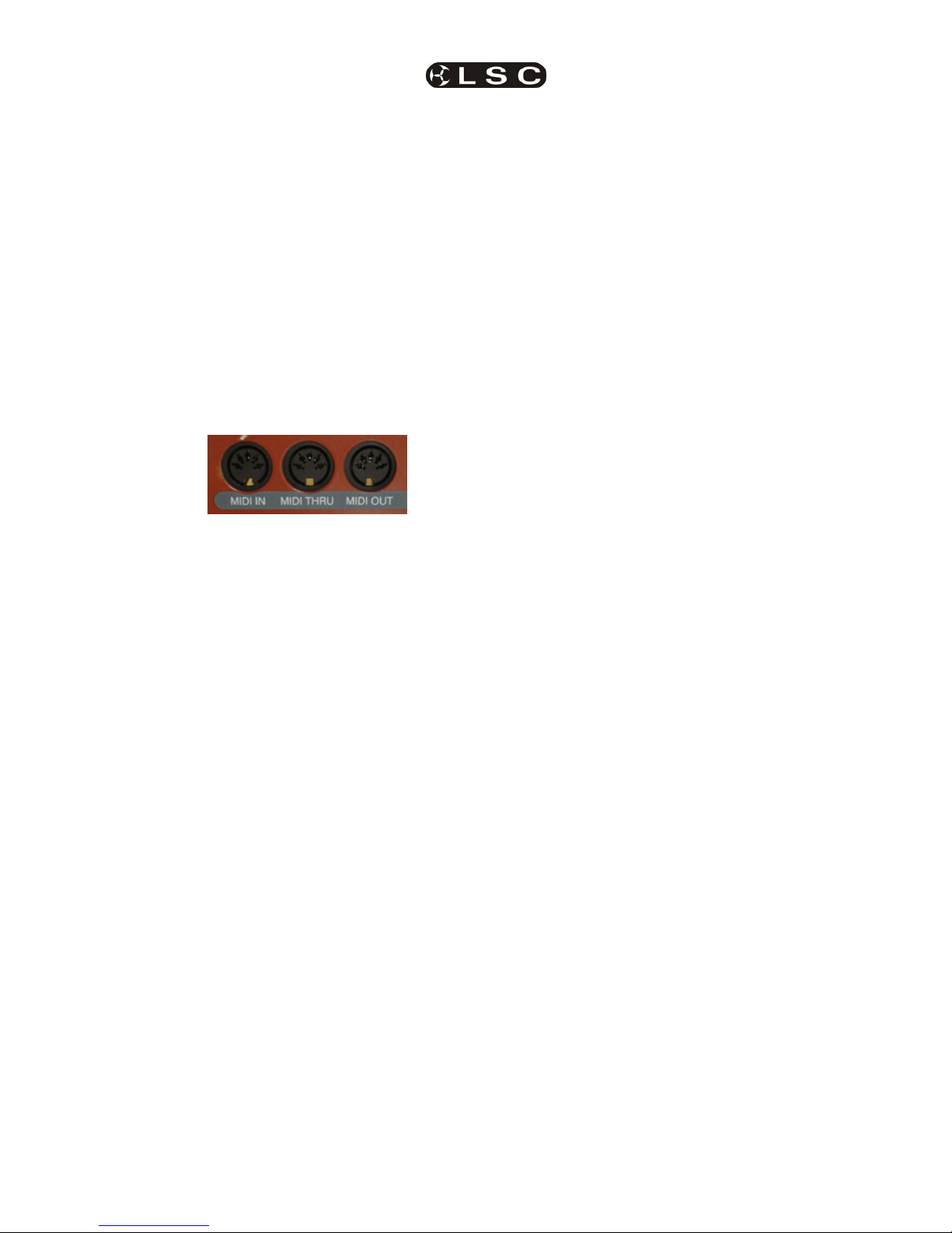
2.11.2 MIDI
MIDI (Musical Instrument Digital Interface) is an
international standard for data communication
between musical instruments, computers and
other equipment such as lighting desks.
The possibility exists to either control lighting
channels from a MIDI keyboard or a computer
with a MIDI output and suitable sequencing
software or to control a MIDI device from the
maXim.
Three MIDI connectors are provided on the rear of
the maXim.
See the separate section on “MIDI” for details.
Page 16

maXim MP L(P) XL(P) XXL(P)
Operator Manual V3
Page 10
LSC Lighting Systems (Aust) Pty. Ltd
3 GETTING CONNECTED
3.1 POWER INPUT
An IEC mains input socket is located on the rear
panel and a POWER switch is beside the power
input. The maXim has a universal power supply
that will operate on voltages between 90 volts and
260 volts with a frequency range from 47 to 63
Hz.
3.2 DIGITAL OUTPUTS (DMX 512)
The maXim MP has a single DMX512 connector
and the L, XL and XXL have two DMX512
connectors, one for “Universe 1 DMX slots” and
the second for “Universe 2 DMX slots”.
Connect a DMX data cable from the Universe 1
DMX512 output of the maXim to the DMX512
input of your equipment (moving fixtures,
dimmers, etc) and set the required DMX slots on
your equipment.
Universe 2 is used for complex setups involving
more than 512 DMX slots or when equipment has
been split into different groups.
For example, all moving lights on universe 1 and
conventional dimmers on universe 2.
3.3 VIDEO MONITOR
Connect a SVGA (or better) computer monitor to
the 15 pin VIDEO connector on the rear of the
maXim.
3.4 SWITCHING ON
At this point, with the mains power and DMX
connected, the maXim is ready to be operated.
Switch on the “POWER” switch on the rear of the
maXim. After briefly displaying the opening
message, the maXim will commence operating in
exactly the same state that it was in when it was
last switched off. All the scenes, stacks, chases,
patches etc will be as they were.
3.5 SWITCHING OFF
The maXim has an inbuilt back up power supply.
When the power is switched off you will hear a
click followed a few seconds later by another click.
The maXim keeps operating on its own power
supply until the second click is heard. During this
time all memories are automatically saved to non
volatile storage.
NOTE: In the event of a short loss of mains
power (a “brown out”) the maXim will continue
to operate for a few seconds due to the
storage capacity of its internal power supply.
3.6 POWER SUPPLY RESET
In the unlikely event that your maXim does not
shut down after the second click (above) you can
force it to do so by momentarily pressing the
power supply reset switch. Remove the power
then insert a small insulated pointer into the hole
to the left of the “DMX UNIVERSE 1” connector.
3.7 FUSE
A 0.5Amp slow blow fuse is located in a slide out
tray beside the mains input socket. Should the
fuse blow, remove the mains lead and slide out
the fuse tray. Pop out the blown fuse and replace
it with a 0.5 Amp slow blow fuse. A spare fuse is
provided in the slide out fuse tray. Replace the
spare fuse if you use it.
3.8 DESK LAMP
The maXim MP has a single desk lamp socket
and the other models have two sockets. The
sockets provide both power and mounting for a
goose-neck desk lamp. There is an internal selfresetting thermal fuse for the power to the lamp.
3.9 USB CONNECTORS
The top USB connector accepts a USB “flash
disk” for the external storage of your maXim
shows and also for software upgrades. The
bottom USB connector
accepts a trackball or mouse
for Pan and Tilt control of
fixtures
3.10 CAPTURE
Capture is a programme that lets you simulate
your lighting shows on a computer. See the
separate “Capture” section for details
Fuse Holder
DMX Universe 1 Desk Lam
p
DMX Universe 2 Desk Lamp 2
Power Supply Reset
Power Switch
Page 17

maXim MP L(P) XL(P) XXL(P)
Operator Manual V3
LSC Lighting Systems (Aust) Pty. Ltd.
Page 11
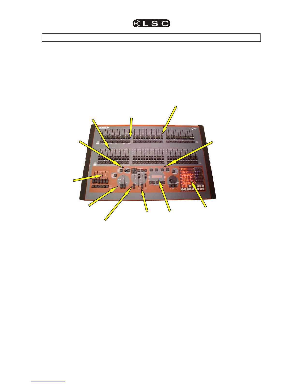
4 FRONT PANEL TOUR
The maXim MP, L(P), X L(P), XX L(P) all vary in layout and in the quantity if faders. This front panel tour
describes the maXim L(P). The location of some controls might be different on your model of maXim but
the names and operation are the same as described here.
4.1 YELLOW BANK FADERS
Control the intensity of dimmers or fixtures
patched to them.
4.2 YELLOW BANK MASTER
• Controls the overall level of the Yellow bank
faders.
• In WIDE mode, it controls the overall level of
the Yellow bank faders and the Red bank
faders.
4.3 MODE RED BANK BUTTON
Selects the current function for the RED bank
faders. The choices are;
• preset.
• wide.
• playback.
4.4 RED BANK FADERS
The Red bank of faders has different functions
depending upon the current “MODE” as selected
by the mode red bank button.
• Preset mode. The Red bank of faders provide
a duplicate of the Yellow bank.
• Wide mode. The Red bank of faders control
the intensity of dimmers or fixtures patched to
channels 25 (37, 49, 61) to 48 (72, 96, 120).
• PLAYBACK mode. The Red bank of faders
become PLAYBACKS. Each Playback can
control the level of a recorded Scene or Chase
or it may be empty (does nothing). There are 9
pages of memory for the red playbacks and the
function of each playback depends upon the
contents of the currently selected red page.
You determine what each red page contains
when you record (or copy) scenes, chases or
stacks into them. Although stacks can be
recorded on the red bank (stored in red bank
memory), they can only be played back on the
stack master.
4.5 RED MASTER
• In PRESET mode, it controls the overall level
of the Red bank.
• In WIDE mode it has no function.
• In PLAYBACK mode it controls the overall
level of the Red Playbacks (Scenes or
Chases).
4.4
4.5
4.8
4.1
4.6
4.24.7
4.8
4.8 4.10 4.9
4.11
4.12
4.13
maXim L (P)
4.3
4.19
Page 18

Front Panel Tour maXim MP L(P) XL(P) XXL(P)
Operator Manual V3
Page 12
LSC Lighting Systems (Aust) Pty. Ltd
4.6 BLUE PLAYBACKS (L,XL & XXL)
The blue bank of faders are dedicated
PLAYBACKS. Each Playback can control the level
of a recorded Scene or Chase or it may be empty
(does nothing). There are 9 pages of memory for
the blue playbacks and the function of each
playback depends upon the contents of the
currently selected blue page. You determine what
each blue page contains when you record (or
copy) scenes, chases or stacks into them.
Although stacks can be recorded on the blue bank
(stored in blue bank memory), they can only be
played back on the stack master.
4.7 BLUE MASTER (L,XL & XXL)
It controls the overall level of the Blue Playbacks
(Scenes or Chases).
4.8 FLASH/ASSIGN [f/a] BUTTONS
Below each fader in the fader section is a
FLASH/ASSIGN button with an integral red
indicator LED.
As their name implies, these are multi purpose
buttons.
They may be used to:
• FLASH (or bump) the contents of their
particular fader, be it a channel, chase or a
scene. (See also FLASH level and ADD/SOLO
button below).
• Provide a NUMERIC SELECTION function.
When the “number” of a channel, fixture,
scene, stack, chase, preset, etc needs to be
entered, the appropriate Flash/Assign button
“number” is pressed. To assist you in making a
selection, valid buttons will flash when an entry
is required.
• In conjunction with the FUNCTION button, the
f/a buttons select various secondary functions
such as PATCH, SETUP, etc as indicated
below the f/a buttons.
• Provide alphanumeric entry when typing
names.
4.8.1 Button Numbering
Between each fader in the Yellow bank and its
associated f/a button is a number that indicates
the channel/fixture that the fader and f/a button
control. (Letters of the alphabet are also printed
and are used when entering names).
Between each fader in the Red bank and its
associated f/a button are two numbers;
• The LARGER font indicates the channel
number of the fader and f/a button when in
PRESET mode.
• The
SMALLER font indicates the channel
number of the fader and f/a button when in
WIDE mode.
• The LARGER font also indicates the number
of a particular SCENE, STACK or CHASE.
• The
SMALLER font also indicates channel
numbers when editing scenes or chase or
stack steps, when viewing channel levels on
the FLASH/ASSIGN button LED indicators
(refer below) or when patching.
The LED indicators in each f/a button are also
multi purpose.
5
CHANNEL LEVEL INDICATORS
The brightness of each indicator is proportional to
the level of its channel. The red bank indicates the
level of the channel numbers printed in the
SMALLER font.
• In normal operation, they indicate the level of
their particular channel at the output of the
maXim.
• In edit mode they indicate the level of their
particular channel in the Scene, Grab or Step
of a Chase or Stack that is being edited.
5
VALID ENTRY BUTTON INDICATORS:
When you are required to make a numeric entry
or Secondary Function selection, only valid
buttons will be active and their LED indicators will
light to indicate to you that an entry is required.
5
FADE IN PROGRESS INDICATORS:
The indicator for each Playback flashes slowly
whilst a timed fade is in progress.
4.9 MASTERS FLASH/ASSIGN BUTTONS
Used to FLASH (bump) the contents of their
particular master. (See also FLASH level and
ADD/SOLO button below). The brightness of their
LED indicators shows the level of the master at
the output of the maXim. It also will flash slowly
whilst a timed fade is in progress.
4.10 IN & OUT TIME FADERS
Control the IN and OUT fade times of the masters.
They may also be individually assigned to control
the IN or OUT fade times of any scene or step of
a stack. The current time setting of each fader is
shown on the display when its fader is moved or
presses of the FUNCTION button will toggle
through the two time settings.
4.11 FLASH LEVEL & ADD/SOLO BUTTON
The level control sets the level to which any
Channels, Playbacks, or Masters will be flashed
when their respective Flash/Assign button is
pressed.
The “add/solo” button toggles the Add/Solo mode
between “Add” and “Solo” as shown by a red
indicator in the Add/Solo button which flashes in
SOLO mode.
• In ADD mode, when a FLASH/ASSIGN button
is pressed, the channels that are being flashed
will come on (at the level of the FLASH level
master), and normal output is not affected.
• In SOLO mode, when a FLASH/ASSIGN
button is pressed, the channels that are being
flashed will come on (at the level of the FLASH
level master), and the normal output of the
maXim will be blacked out, leaving only the
channels that are being flashed on stage.
Note: Multiple Flash/Assign buttons may be
pressed at the one time.
Page 19

maXim MP L(P) XL(P) XXL(P) Front Panel Tour
Operator Manual V3
LSC Lighting Systems (Aust) Pty. Ltd.
Page 13
4.12 PAGE RED BANK BUTTON & DISPLAY
• In “p'back (playback) mode” it is used to select
the current page (1 to 9) of red memory that is
loaded into the red bank of playbacks.
• When recording, editing or copying scenes,
stacks or chases, it is used to select the
required red page (1 to 9) for the scene, stack
or chase.
Repeated presses of the Page button will step
through the pages.
To directly select a page;
HOLD [page red bank] then quickly tap [f/a] (red
1 to 9).
The displays beside the button shows the red
page number.
4.13 PAGE BLUE BANK BUTTON & DISPLAY
(L,XL & XXL only)
• Used to select the current page (1 to 9) of blue
memory that is loaded into the blue bank of
playbacks.
• When recording, editing or copying scenes,
stacks or chases, it is used to select the
required blue page (1 to 9) for the scene, stack
or chase.
Repeated presses of the Page button will step
through the pages.
To directly select a page;
HOLD [page blue bank] then quickly tap [f/a]
(blue 1 to 9).
The displays beside the button shows the blue
page number.
Hint: The maXim can show the types of object
recorded in each page. If you HOLD either
[page red bank] or [page blue bank], playback
flash/assign buttons in that bank containing
Scenes will light, playbacks containing
Chases flash quickly, playbacks containing
Stacks flash slowly and empty playbacks are
not lit.
4.14 STACK MASTER
It controls the overall level of the Stack Playback.
4.15 STACK FLASH
It is a multi purpose button and can be used to;
• Select the Stack Master when assigning,
editing or copying a stack.
• FLASH (bump) the contents of the Stack
Master. (See also FLASH level and
ADD/SOLO button).
The brightness of its LED shows the level of the
master at the output of the maXim.
4.16 > (STACK)
It starts a crossfade from the current step to the
next step. In conjunction with the step/stop button
(below) it steps (snaps) a stack in the forward
direction.
4.17 < (STACK)
It starts a crossfade from the current step to the
previous step. Only one reverse crossfade is
allowed. In conjunction with the step/stop button
(below) it steps (snaps) a stack in the reverse
direction.
4.18 STEP/STOP (STACK)
It stops a crossfade. It momentarily runs a
stopped crossfade when held down. In
conjunction with the > and < buttons it steps
(snaps) a stack in the either direction.
4.19 PATPAD
The PatPad consists of a touch screen with an
overlay that divides the touch screen into separate
areas. The small areas are virtual buttons and the
long areas are displayer scroll bars.
The touch screen can be operated with either your
finger or a stylus such as those available for hand
held computing devices. The scrolling bar areas
act like control wheels and can be either moused
(scrolled) or they can be tapped.
The PaTPaD is used to control the
parameters of moving fixtures and to “store” their
parameter settings into the memory of the
playbacks. The PaTPaD is also used to access
“groups”, “palettes”, “presets”, “filters”, “effects”,
“fans” and fixture patching. The PaTPaD is
extensively described in the “BASIC FIXTURE
PROGRAMMING” and “ADVANCED FIXTRE
PROGRAMMING” sections.
4.17 4.16
4.15
4.18
4.14
4.19
Page 20

Front Panel Tour maXim MP L(P) XL(P) XXL(P)
Operator Manual V3
Page 14
LSC Lighting Systems (Aust) Pty. Ltd
4.20 DOT MATRIX DISPAY & LEDS
The display is used to scroll messages and
prompts and to show names and numbers. The
small labelled LEDS beside the display are used
to define the numbers shown on it. For example;
• If the CHAN LED is lit, then the number
displayed is a channel number.
• If the LEVEL LED is lit, then the number
displayed is a channel level.
Comprehensive information (including these
messages) are also shown on the video output.
4.21 RECORD SCENE BUTTON
Used to select RECORD SCENE mode or to
record a snapshot of the output of the maXim as
a step in a stack or a step in a chase (or into the
Grab master on the MP model).
4.22 RECORD CHASE BUTTON
Used to select RECORD CHASE mode and to
complete the recording of a chase when all the
desired steps have been added.
4.23 RECORD STACK BUTTON
Used to select RECORD STACK mode and to
complete the recording of a stack when all the
desired steps have been added.
4.24 ASSIGN COPY BUTTON
Used to:
• Assign a stack to the stack master.
• Copy scenes, chases or stacks from one
memory location to another.
• Copy scenes, chases or stacks to or from
the Grab master. (MP model).
• Copy a Snapshot from the Grab master to
a memory. (MP model).
4.25 SELECT BUTTON
Used to take control of a playback. The recorded
memory is not changed, only the way that it is
currently being played back.
Press [select] [f/a] (playback to control).
Repeatedly press [function] to cycle though the
parameters that you can control as indicated by
the LEDs beside the display.
When finished, press [select] again to de-select it.
The changes that you have made are retained in
the Playback until such time as the scene or
chase is replaced on that Playback (by changing
pages or mode).
To restore the original memory to the playback
press [copy], [f/a] to the same [f/a].
“Select” is most useful for making one off changes
during a performance or for experimenting with
changes without affecting the memory.
4.26 EDIT BUTTON
When pressed, it selects Edit mode. You may
then choose to Edit any Scene, Chase, Stack, the
contents of the Grab master (MP model).
To edit the patch;
HOLD [function] tap [f/a] (patch). Press [edit
].
4.27 REMOVE BUTTON
Used to:
• Remove the contents of the Stack and Grab
masters.
• Delete memories, patches or steps of stacks or
chases.
• Remove characters from names.
4.20
4.21 4.22 4.23 4.24
4.25
4.26
4.27 4.28 4.29
4.30
4.32
4.31
4.33
4.34
4.3
Page 21

maXim MP L(P) XL(P) XXL(P) Front Panel Tour
Operator Manual V3
LSC Lighting Systems (Aust) Pty. Ltd.
Page 15
4.28 ADD BUTTON
Used to:
• Insert steps in a stack or chase when editing.
• Add a 1 to 1 patch
• Insert spaces in names
4.29 FUNCTION BUTTON
• When pressed during normal operations, it
causes the display to momentarily show the
current time “IN” or “OUT” settings of the time
faders, whilst it is held down. Subsequent
presses will toggle between the two time
settings as indicated by the “in” or “out” LEDs
above it.
• When editing, pressing [function] steps
through the various parameters that can be
changed as indicated on the LEDs above the
function button.
• After pressing [select], [f/a], pressing
[function] steps through the various
parameters that can be changed on the
selected playback.
• It accesses the secondary functions such as
reset, (USB) disk or patch etc as indicated
below the yellow and red bank [f/a] buttons.
To perform secondary functions;
HOLD [function] tap [f/a] (secondary function
as printed below red and yellow bank “f/a”
buttons).
4.30 EDIT WHEEL
Continuously rotatable in either direction and can
be used to:
• Set fade and link times plus chase rate and
crossfade when recording or editing.
• Adjust the level of channels when editing.
• Adjust Sound To Light parameters.
• Select DMX address numbers when patching.
• Select characters for names.
• Scroll the V1 or V2 video displays.
• Adjust selected parameters on the PatPad.
4.31 EDIT WHEEL INDICATOR
Lights when the EDIT Wheel is active.
4.32 > (YES) BUTTON
• Runs a selected or edited chase in the
FORWARD direction.
• Steps a stack forward when editing.
• Increments through the DMX address numbers
when patching.
• Answers “YES” to a request from the maXim.
• Select the next parameter on the PatPad.
4.33 < (NO) BUTTON
• Runs a selected or edited chase in the
REVERSE direction.
• Steps a stack backwards when editing.
• Decrements through the DMX address
numbers when patching.
• Answers “NO” to a request from the maXim.
• Select the previous parameter on the PatPad.
4.34 STEP STOP (OK) BUTTON
• Used to STOP a selected or edited chase or
STEP a stopped chase.
• Answers “ok” to a request from the maXim.
Page 22

maXim MP L(P) XL(P) XXL(P)
Operator Manual V3
Page 16
LSC Lighting Systems (Aust) Pty. Ltd
5 PATCHING
5.1 INTRODUCTION
When dimmers are connected, the maXim needs
to know the DMX slot of each dimmer and which
maXim channel is to be used to control each
dimmer.
When lighting fixtures or other DMX controlled
devices are connected, the maXim needs to know
each fixture’s manufacturer, model and starting
DMX slot. A fixture number is then assigned to the
fixture allowing it to be controlled by the maXim.
If no patches exist, either due to a “Total Reset” or
if all patches have been removed (below) the
patch will be automatically bypassed giving a
direct 1 to 1 connection between maXim channel
numbers and their matching DMX slot numbers.
When any patch is made by the user, the bypass
is automatically removed and only the users
patches will exist.
5.2 PATCHING DIMMERS
5.2.1 PATCHING
Patching is performed by “editing the patch”.
To edit the patch;
HOLD [function], tap [patch], press [edit].
If a PaTPaD is fitted, ensure that the [PM] button
beside “DIMMER” is flashing. If not, press [PM]
(DIMMER).
To select the dimmers DMX slot number, press
[<] or [>] or rotate the EDIT Wheel.
To patch the selected DMX slot to a channel
number, press the [f/a] button of the channel
number (any yellow or red f/a button).
The channel f/a button will flash to show the
patch.
Select another DMX slot with the EDIT wheel, [<]
or [>] and patch it to a channel by pressing the
channels [f/a] button. Continue to select DMX
slots and patch them to maXim channels.
Patched channels f/a buttons remain lit. As each
patch is made, the “V2 Output & Patch” video
shows the channel number and name, DMX slot
and patch level.
When scrolling through the DMX slots, as each
slot number is selected, if a channel is patched to
that slot, its f/a button will flash.
When finished patching, press [edit]. The patch is
automatically saved.
5.2.2 PATCHING MULTIPLE SLOTS
To automatically patch a sequential range of DMX
slots to a sequential range of channels, edit the
patch (above), then select the first DMX slot
number in the sequence. HOLD the [f/a] button of
the channel number to be patched to that slot then
tap the [f/a] button of the channel to be patched to
last DMX slot number in the sequence. All
channels in the selected range are automatically
patched to their respective slots.
For example, to patch a rack of 12 dimmers with a
starting DMX slot of 100 to maXim channels 13 to
24 respectively, press [<] or [>] or rotate the EDIT
Wheel to select DMX slot 100, then HOLD [f/a]
(13) and tap [f/a] (24).
5.2.3 SET A PATCH LEVEL
All patches can have a proportional patch level.
See “INTENSITY PATCH LEVEL” below.
5.2.4 UNPATCH A DMX SLOT FROM
A CHANNEL
To delete a single patch, edit the patch (above)
and select the DMX slot (above) then press
[remove].
The display scrolls, “Delete patch to DMX#?”
Press [yes].
Alternately, select the DMX slot and set the
proportional patch level to zero.
5.2.5 REMOVE All PATCHES
To remove ALL patches;
HOLD [function], tap [patch].
Press; [remove], [yes].
The patch is now automatically bypassed.
5.2.6 1 TO 1 PATCH
A 1 to 1 patch is available to speed the patching
process. It directly connects each maXim channel
number to its matching DMX slot number.
To add a “1 to 1 patch”;
HOLD [function], tap [patch].
Press [add], [yes].
Note; Adding a 1 to 1 patch will replace any
existing patches.
5.3 PATCHING FIXTURES
5.3.1 TEMPLATE LIBRARY
In order for the maXim to control a fixture, it
needs to know all of the functions of that fixture. It
gets this information from a computer file called a
Fixture Template. This file tells the maXim the
function of each control channel for that type of
fixture and it also defines the unique parameter
controls and labels that will appear on the
PaTPad and video screen. Every different type of
Fixture that you control from the maXim requires
a Template. Many popular templates are already
loaded in the maXim
’s library plus additional
templates are available from the LSC website;
www.lsclighting.com.au
If the template for your fixture is not on the
website you can contact LSC by posting a request
on the LSC forum providing details of
manufacturer, model and software version
number. The forum URL is;
http://forums.lsclighting.com.au
Page 23

maXim MP L(P) XL(P) XXL(P) Patching
Operator Manual V3
LSC Lighting Systems (Aust) Pty. Ltd.
Page 17
Detailed instructions on how to write your own
Templates using a text editor program on a
personal computer can also be obtained from the
LSC forum.
Templates are loaded into the maXim library via
the disk drive
The maXim stores its Templates in a library that
can hold up to 64 Fixture Templates. When you
want to use a particular model of Fixture, you
select its Template from the library and load it into
the patch. The maXim can have up to 10 different
types of Fixture Templates (from the library) in
use in the patch at the same time.
5.3.2 VIEW LIBRARY CONTENTS
To see if the Templates for the Fixtures you are
using are in the maXim’s Fixture library, press
[menu], [library], [view].
Templates are organised in the library by
manufacturer and model. The PaTPad shows a
list of Fixture manufacturers. If more than 6
manufacturers are loaded in the library, press the
“>” or “<” symbol on the Fixture Displayer to
change pages.
Press the [PM]
button beside the required
manufacturers name. The PaTPad shows a list of
Template names (models) from that manufacturer.
If more than 6 templates for that manufacturer are
loaded in the library, press the “>” or “<” symbol
on the Fixture Displayer to change pages.
Press [menu] to finish.
5.3.3 ADDING TEMPLATES
To add a template to the library, insert the floppy
disk containing the template into the maXim disk
drive then press;
[menu], [library], [add].
The display shows the Templates on the disk. If
more than 6 are on the disk, press the “>” or “<”
symbol on the Fixture Displayer to change pages.
Press the [PM] button corresponding to the
required Template.
5.3.4 ADDING ALL TEMPLATES
If the disc contains many Templates they can all
be added to the library in a single operation.
Press;
[menu], [library], [add], [all], [yes].
5.3.5 COPY A TEMPLATE TO DISK
Templates can be copied from the library to disk
so that they can be archived or edited. Press
;
[menu], [library], [CopyToDsk].
Use the [PM] buttons to select the manufacturer,
then the model.
5.3.6 REMOVE A TEMPLATE
To remove a Fixture Template from the library;
press;
[menu], [library], [remove].
Use the [PM] buttons to select the manufacturer,
then the model.
5.3.7 REMOVE ALL TEMPLATES
To remove the entire contents of the library; press
[menu], [library], [remove], [all], [yes].
5.3.8 CLEARING THE PATCH
If you are patching a new installation of fixtures it
is advisable to clear the patch.
Hold [function], tap [patch]. Press [remove],
[yes].
Warning. This will erase ALL existing patches. If
you need to keep the patch, save your show to
disk.
5.3.9 PATCHING FIXTURES
Hold [function], tap [patch], press; [edit].
The PaTPad shows;
DIMMER ☼
LIBRARY ●
The PM button beside “DIMMER” will be flashing,
indicating that the maXim is ready to patch a
dimmer. Before you can patch a Fixture, its
Template must be loaded from the library into the
patch.
5.3.10 LOADING TEMPLATES INTO
THE PATCH
To load a Fixture Template into the patch, edit the
patch (above) then press the [PM] button beside
“LIBRARY”. The PaTPad shows a list of Fixture
manufacturers in the library. If more than 6
manufacturers are loaded, press “>” or “<”on the
Fixture Displayer to change pages. Press the [PM]
button beside the manufacturers name. The
PaTPad shows a list of Template names (models)
from that manufacturer that are in the library. If
there are more than 6 Templates (models) for that
manufacturer, press “>” or “<”on the Fixture
Displayer to change pages.
Press the [PM] button beside the required
template to load it into the patch.
The PaTPad shows;
DIMMER ●
SCAN-X ☼
LIBRARY ●
In this example the selected Fixture is a fictitious
“scan-x” but you will see the name of the actual
Template you selected. The [PM] button beside it
will be flashing, indicating that the maXim is ready
to patch that Template (type of Fixture). This
Template is now loaded into the patch (from the
library) and does not need to be loaded again.
You can use it every time that you need to patch
that type of Fixture. If you are using several
Page 24

Patching maXim MP L(P) XL(P) XXL(P)
Operator Manual V3
Page 18
LSC Lighting Systems (Aust) Pty. Ltd
different types of Fixtures you can load their
Templates now or you can patch the currently
loaded Fixture (see below) then return to the
library later and load the other Templates. To load
more Templates now press the [PM] button
beside “LIBRARY” and make your selection as
above.
5.3.11 DMX SLOT AND FIXTURE
NUMBER
Each Fixture that you patch will have its own DMX
slot (that you set on that Fixture). This is the
starting DMX slot for that Fixture and each Fixture
will use a quantity of DMX slots, as defined in its
Fixture Template.
Select the template for the type of fixture you want
to patch by pressing the [PM] button beside its
name. The [PM] button will flash. All patches that
you now make will use this (flashing) template.
Select the starting DMX slot of the fixture to be
patched by pressing [<] or [>] or rotating the EDIT
wheel .
The maXim has 2 DMX universes (2 DMX
outputs) and uses “U1” or “U2” to indicate DMX
Universe 1 or Universe 2. When the DMX slot
number is incremented above the highest number
in Universe 1 (U1-512), it changes to the first slot
in Universe 2 (U2-1).
To patch a fixture you must give it a “Fixture
Number” by pressing a yellow or red [f/a] button.
When a fixture number is selected, the maXim
automatically patches all of the remaining DMX
slots for that Fixture according to the information
contained in the Fixture Template. The DMX slot
number automatically advances to the slot after
the last slot used by the patched Fixture, ready for
the next fixture (or dimmer) to be patched.
To patch further Fixtures of the same type
(flashing [PM] button on the PaTPad), select the
starting DMX slot of the Fixture by pressing [<] or
[>] or rotating the EDIT wheel , then give it a
Fixture number by pressing; [f/a] (Fixture
Number).
To patch a different type of Fixture, select its
template by pressing the [PM] button beside its
template name (it flashes) then select the starting
DMX slot of the Fixture by pressing [<] or [>] or
rotating the edit wheel , then give it a Fixture
number by pressing; [f/a] (Fixture Number).
Each patch that is made will use the Template
indicated by the flashing [PM] button. If the
Template you require is not shown, load it from
the library as above.
When finished patching press; [edit]. The patch is
automatically saved.
5.3.12 PATCHING MULTIPLE
FIXTURES
Whilst patching (above), you can automatically
patch a sequential range of Fixtures of the same
type with contiguous DMX slots, to a sequential
range of Fixture Numbers.
Select the DMX slot of the first Fixture by pressing
[<]
or [>] or rotating the edit wheel .
Select the Fixture Template on the PaTPad.
HOLD the [f/a] button of the first Fixture Number
then tap the [f/a] button of the last Fixture Number
in the sequence.
All Fixtures in the selected range are
automatically patched.
For example, to patch 10 Fixtures of the same
type to Fixture Numbers 6 to 16 respectively and
with the starting DMX slot of the first Fixture set to
100, press [<] or [>] or rotate the edit wheel to
select DMX slot 100. HOLD [f/a] (6) and tap [f/a]
(16)).
All patches for all 10 Fixtures are automatically
made.
If finished patching press; [edit]. The patch is
automatically saved.
5.3.13 PATCHING SCROLLERS OR
FIXTURES WITH EXTERNAL DIMMERS
Colour scrollers and some brands of fixture
require a separate dimmer to control their
intensity. The dimmer usually has a DMX slot
number that is not related to the DMX slot
numbers used by the scroller or fixture. Whilst
patching (above), select the DMX slot of Fixture
by pressing [<] or [>] or rotating the EDIT wheel .
Select the Fixture Template on the PaTPad.
Patch the fixture to a fixture number by pressing
[f/a] (fixture number). The maXim display scrolls
the message, “Fixture needs HTP channel”. The
maXim knows that this scroller or fixture needs an
external dimmer because it is defined in its
template. Press; [OK]. Use the EDIT wheel or [<]
or [>] to select the DMX slot of the external
dimmer then press; [OK]. The fader of the ”fixture
number“ button that was selected for the fixture
number now controls the intensity of the dimmer
and the PaTPad controls the scroller colours or
fixture parameters. If finished patching press;
[edit]. The patch is automatically saved.
5.3.14 INTENSITY PATCH LEVEL
All fixture intensity attributes and dimmers can
have a proportional (adjustable) patch level.
When patching (above), select the DMX slot of the
intensity channel (use EDIT wheel , [<] or [>]).
The fixtures (or dimmers) [f/a] button will flash
showing the existence of the patch. Hold down
the FLASHING [f/a] button and the display shows
the patch level.
Whilst holding down the [f/a] button, rotate the
edit wheel to set the patch level. The level of the
patch is shown on the display. If you inadvertently
Page 25

maXim MP L(P) XL(P) XXL(P) Patching
Operator Manual V3
LSC Lighting Systems (Aust) Pty. Ltd.
Page 19
select the DMX slot of a fixtures LTP attribute
(instead of the HTP intensity attribute) the maXim
will automatically adjust the patch level of the HTP
intensity attribute associated with that fixture.
5.3.15 PATCH INDICATORS
Whilst you are patching, the LEDs of any Fixture
Number buttons that are patched are lit to show
that they have been used.
As each DMX slot is selected (with [<] or [>] or the
EDIT wheel), if the displayed DMX slot is used
(patched), it’s Fixture Number LED will flash.
The “V2 Output & Patch” video screen shows the
Fixture Number and name, parameter names,
DMX slots and DMX levels for each Fixture.
The “FIXTURES” pop up video window also
shows each Fixture name beside its number.
5.3.16 REMOVING A FIXTURE FROM
THE PATCH
If a fixture is no longer required, it can be removed
from the patch
HOLD [function], tap [patch].
Press [edit].
Select any DMX slot that is used by the Fixture to
be removed.
Press; [remove], [yes].
When finished patching press; [edit].
5.3.17 REMOVING A TEM P LATE
FROM THE PATCH
If a template is removed from the patch, all
patches for that type of fixture are also removed.
To remove a Template from the patch;
HOLD [function], tap [patch]. Press [edit].
The PaTPad shows the Templates in the patch,
for example,
DIMMER ●
TRACKSPOT ●
MAC250 ☼
LIBRARY ●
Press; the [PM] button beside the template to be
removed (it flashes).
Press; [clear], [yes], [edit].
5.3.18 LOADING SHOWS
CONTAINING TEMPLATES
When a show is loaded from disc onto the
maXim, the system checks to see if the templates
in the show are already in the library. It does this
by comparing manufacturer and model names. If
the templates are already in the library, it then
compares the version numbers. The highest
version is always used.
• If the library template is the newer
version, it will be used for the show and
also saved to disk when the show is
saved replacing the older show template.
• If the show (disk) template is the newer
version, it will be used for the show and
also copied into the library, replacing the
older library template
5.3.19 EDITING FIXTURE NAMES
The default name of each Fixture as shown on the
video screens is defined in its Template. Hence all
Fixtures of the same type have the same name.
You can individually edit the name of every
Fixture to make it more descriptive for your
application.
To edit a name, HOLD [function], tap [f/a]
(name).
Press; [f/a] (Fixture Number).
Either rotate the edit wheel or press the yellow
bank [f/a] buttons for the desired characters as
labelled below the buttons. Press [<] or [>] to
move the cursor and press [remove] or [add] to
remove or add characters or spaces.
When finished, press [ok].
5.4 SAVING A PATCH
Whenever you finish editing a patch it is
automatically saved. When you save or load a
show from disk, you copy the entire contents of
the maXim’s memory. This includes the Patch.
See the “UTILITIES” section for details.
5.5 INVERT PAN OR TILT
You can invert the operation of the PaTPaD pan
and tilt displayers. This makes operation easier
when a fixture is rigged such that mousing a
displayer from left to right, pans the fixture from
right to left or if it tilts in the wrong direction.
To invert the operation of a fixtures pan or tilt
parameters the fixture must be loaded on the
PaTPaD.
Press [get], [f/a] (fixture number).
Press [menu] [PM] (INVERT)
The PaTPaD shows the selected fixture number
and the current state of its pan and tilt as either
“normal” (green PM button) or “inverted” (red PM
button).
PAN
normal
TILT
inverted
Fx #
To reverse a parameter press its flashing [PM]
button.
Tapping either end of the [fixture displayer]
steps through the fixtures loaded on the PaTPaD.
When finished press [menu].
Video screens 1 and 2 indicate inverted pan or tilt
parameters as follows;
PAN -i
TILT-i
Page 26
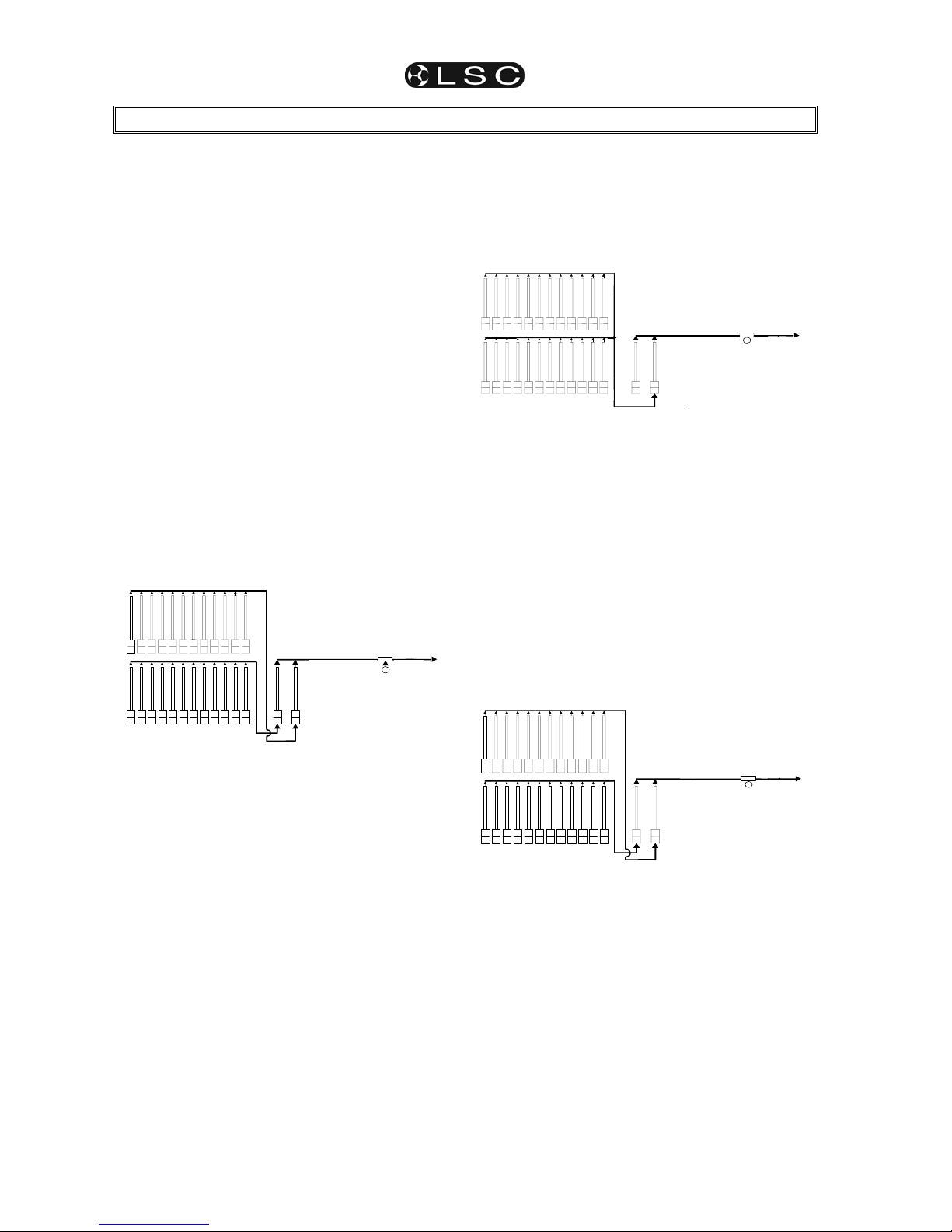
maXim MP L(P) XL(P) XXL(P)
Operator Manual V3
Page 20
LSC Lighting Systems (Aust) Pty. Ltd
6 MODES OF OPERATION
6.1 OVERVIEW
The maXim has several banks of faders.
• The Yellow bank always controls the levels of
channels/fixtures 1 to 24 (36, 48, 60)
• The Red bank has different functions as
selected by the “mode red bank” button;
• PRESET mode. The Red bank controls the
levels of channels/fixtures 1 to 24 (36, 48,
60). (A duplicate of the Yellow bank).
• WIDE mode. The Red bank controls the
levels of channels/fixtures 25 (37, 49, 61) to
48 (72, 96, 120). (An extension of the
Yellow bank providing double the number
of channel/fixture faders)
• PLAYBACK mode. The Red bank faders
become PLAYBACKS and control the
levels of recorded Scenes or Chases.
You may freely change red modes at any time
during your operation of the maXim and the
current red mode is always shown by the “LED”
MODE indicators.
Each mode has its particular advantage for
different types of operations.
6.2 PRESET MODE
RED
ADD/SOLO
YELLOW BANK
RED BANK
MASTERS
YELLOW
1 2 3 4 5 6 7 8 9 10 11 12
1 2 3 4 5 6 7 8 9 10 11 12
CHANNELS 1-12
CHANNELS 1-12
OUTPUT
Simplified diagram of a maXim in PRESET mode.
You can create a lighting look by fading up your
required channels on one of the colour coded
banks and fading up the same colour master. By
keeping the other master faded down, another
look can be preset on the duplicate set of channel
faders without the channels being revealed on
stage. The new look is revealed by fading up its
master whilst the first look is faded down with its
master. The next look may now be “preset” on the
bank that has just been faded down. The fade
times of the masters are set by the IN and OUT
time faders.
6.2.1 PRESET ADVANTAGE
This simple mode of operating is most useful in
unrehearsed situations where the next “look”
needs to be created “on the fly”. The channel
faders provide instant “hands on”.
6.2.2 PRESET DISADVANTAGE
Only half of the possible maXim channels/fixtures
can be intensity controlled by dedicated faders.
6.3 WIDE MODE
Wide mode utilises both the red and yellow banks
as a single wide bank thus doubling the number of
channel/fixture faders. The yellow faders control
the low numbered channels and the red faders
control the high numbered channels. The yellow
master controls the total output.
RED
GRAB
ADD/SOLO
YELLOW BANK
RED BANK
MASTERS
YELLOW
1
2 3 456
7 8 9 10 11 12
13 14 15 16 17 18 19 20 21 22 23 24
CHAN N ELS 1-12
CHANNELS 13-24
OUTPUT
Simplified diagram of a maXim in Wide mode.
6.3.1 WIDE ADVANTAGE
You have individual access to all of the channels
that are available on the maXim. This is most
useful when you are RECORDING scenes as you
can utilise all channels to create your scenes.
(See “Playback Mode” below).
6.3.2 WIDE DISADVANTAGE
You do not have a second “preset” bank on which
to create the next look and you have less
playbacks.
6.4 PLAYBACK MODE
Selecting Playback mode only changes the
operation of the red bank. The faders of the red
fader bank become Playbacks containing scenes
or chases that you have recorded.
RED
GRAB
ADD/SOLO
YELLOW BANK
RED BANK
MASTERS
YELLOW
1 2 3 4 5 6 7 8 9 10 11 12
1 2 3 4 5 6 7 8 9 10 11 12
PLAYBACKS 1 - 12
CHANNELS 1 - 12
OUTPUT
Simplified diagram of a maXim S in Playback mode.
Scenes, stacks and chases can be recorded or
edited whilst operating in any modes but scenes
and chases can only be played back on the Red
bank when it is in Playback mode.
6.4.1 PLAYBACK ADVANTAGE
During rehearsal (in any mode), each lighting look
can be created and “recorded” into a Scene.
During the show (in Playback mode), the
Playback containing each scene is faded up when
required. The maXim remembers all the channels
and their levels together with the fade times. You
may also use the Red Playbacks to playback
chases that you have recorded.
Page 27

maXim MP L(P) XL(P) XXL(P)
Operator Manual V3
LSC Lighting Systems (Aust) Pty. Ltd.
Page 21
7 MEMORY STRUCTURE
7.1 OVERVIEW
Scenes, Chases and Stacks are stored in non
volatile memory. The red bank has 9 pages of
memory and the blue bank has 9 pages of
memory. Memories are organised by Page
number and f/a (flash/assign) number. Scenes,
chases and stacks share the same memory within
each bank. You determine what each memory
contains when you record (or copy) scenes,
chases or stacks into them.
For example, if a “page and f/a number” location
has been used for a scene, then it cannot be used
for a chase or stack. A chase or stack recorded in
the same location would overwrite the scene.
The red and blue memories are totally separate.
Repeated presses of either;
[page red bank] or [page blue bank]
will step through their 9 respective pages of
memory.
To switch directly to a red page;
HOLD [page red bank] tap [f/a] (red 1 to 9).
To switch directly to a blue page;
HOLD [page blue bank] tap [f/a] (blue 1 to 9).
To see the type of object recorded in each
memory, HOLD either;
[page red bank] or [page blue bank].
A window pops up on the video showing memory
usage and the playback flash/assign buttons in
that bank indicate their contents as follows;
Playback Contents Playback f/a LED
Scene On steady
Chase Fast Flash
Stack Slow Flash
Empty Off
When you press [edit] or [assign copy] or any
[record] or [store] button, all Playback flash/assign
buttons flash twice (to indicate that they are
possible choices), then they show their contents
as above.
If you change pages whilst in “edit”, “assign copy”
or “record” modes, the contents of the selected
page is also shown.
Groups, Presets, Palettes and Filters each have
dedicated memory which is accessed via the
yellow [f/a] buttons.
7.2 “PLAYBACK” MEMORY ACCESS
When the red bank is changed to “scene” mode
or when a red bank page is changed whilst in
“p'back (playback) mode”, the contents (scenes
and chases) of the indicated red page are
COPIED (subject to any “Page Freeze” below)
into the red playbacks.
When a blue bank page is changed, the contents
(scenes and chases) of the indicated blue page
are COPIED (subject to any “Page Freeze” below)
into the blue playbacks.
Stacks occupy memory locations on the red and
blue pages but do not load onto playbacks. They
must be individually COPIED from red or blue
memory to the stack master for playback.
7.3 MODE/PAGE FREEZE
A “MODE/PAGE FREEZE” feature prevents the
contents of a “live” fader from being changed if its
level is above 5% when a mode or page is
changed.
The current contents of any live fader is held until
such time as that fader is faded down below 5%
when it will be automatically updated with its
pending assignment for the new mode or page.
This prevents scenes, chases or channels
“crashing in” on stage if their fader is contributing
to the output when a different mode or page is
selected.
7.4 FREEZE INDICATOR
Whenever there is a pending scene, chase or
channel change due to a 'Mode or Page freeze',
the “LED” indicator in the “mode red bank”
button will flash.
This acts as a warning to you that the contents of
a fader on the red or blue bank may change after
it is faded down.
The video screen also shows the current page
number loaded on each playback.
7.5 “RECORD” MEMORY ACCESS
During recording, storing, editing or copying, you
can directly access any of the memory locations
on any page by using that bank’s [page] and [f/a]
buttons. Changing pages when recording, editing
or copying does not affect the current contents of
a playback.
If you attempt to record, store or copy over an
existing memory a warning will appear on the
maXim’s display. To overwrite the memory either
press [yes] or press the locations [f/a] button a
second time.
To pick a different memory location press;
[page] (optional), [f/a] (new location).
Freeze
indicator
Page 28

Memory Structure maXim MP L(P) XL(P) XXL(P)
Operator Manual V3
Page 22
LSC Lighting Systems (Aust) Pty. Ltd
7.6 SELECT PLAYBACK
When [select], [f/a] is pressed, the copy of a
scene or chase in a playback can be varied
without affecting the original memory.
You can vary a scenes fade times or you can
change the rate, crossfade and mode of a chase.
When [select] is de-selected, the changes are
retained in the playback until a new memory is
loaded onto the playback.
To reload the original memory onto a playback
press;
[copy], [f/a] (to same) [f/a].
7.7 EDIT MEMORY
When [edit], [page] (optional red or blue page),
[f/a] is pressed, the original memory is edited. If
the selected memory is currently loaded on a
playback, then the changes will also be seen on
that playback.
In addition to the changes that can be made by
“select”, “edit” also allows you to change the
contents of a scene or a step in a chase or stack
and to insert or delete steps in a chase or stack.
7.8 EXTERNAL STAORAGE
The top USB connector allows you to plug in a
USB “flash disk” memory device and then save or
load a “show” using the USB disk. A “show”
contains the entire contents of the maXim's
memory. This includes all Scenes, Chases,
Stacks, SyncoBEATs and the Patch.
Blue Page
BUTTON
Blue PAGE 2
1 2 3 4 5 6
Blue PAGE 3
1 2 3 4 5 6
Blue PAGE 4
1 2 3 4 5 6
Blue PAGE 5
1 2 3 4 5 6
Blue PAGE 6
1 2 3 4 5 6
Blue PAGE 7
1 2 3 4 5 6
Blue PAGE 1
1 2 3 4 5 6
Blue PAGE 9
1 2 3 4 5 6
Scenes Stacks or
Chases
1 2 3 4 5 6
Blue Playbacks
Red Page
BUTTON
Red PAGE 2
1 2 3 - - - - - - -34 35 36
Red PAGE 3
1 2 3 - - - - - - -34 35 36
Red PAGE 4
1 2 3 - - - - - - -34 35 36
Red PAGE 5
1 2 3 - - - - - - -34 35 36
Red PAGE 6
1 2 3 - - - - - - -34 35 36
Red PAGE 7
1 2 3 - - - - - - -34 35 36
Red PAGE 1
1 2 3 - - - - - - -34 35 36
Red PAGE 8
1 2 3 - - - - - - -34 35 36
Red PAGE 9
1 2 3 - - - - - - -34 35 36
Scenes Stacks or
Chases
RECORD
EDIT
GRAB
MASTER
1 2 3 - - - - - - - 34 35 36
Red Playbacks
STACK
MASTER
SELECT
BUTTON
ASSIGN
COPY
Blue PAGE 8
1 2 3 4 5 6
Basic Memory structure of a maXim L
Page 29

maXim MP L(P) XL(P) XXL(P)
Operator Manual V3
LSC Lighting Systems (Aust) Pty. Ltd.
Page 23
8 SCENES
8.1 OVERVIEW
A “recorded” SCENE is a snapshot of the
maXims output, together with In and Out fade
time settings and a descriptive name, that is
stored in non volatile memory.
The PaTPaD allows you to “store” scenes that
contain selected fixture parameters. See the
“FIIXTURE PROGRAMMING CONCEPTS”
section for details.
Scenes are recorded by page/scene number.
Page numbers are selected with the [page red
bank] or [page blue bank] buttons and scene
numbers are selected with the red or blue [f/a]
buttons (no blue bank on MP model but a scene
can be recorded onto the MP’s Grab Master).
See the “MEMORY STRUCTURE” section for
more details on banks and pages.
Scene Playback fade times may come from the
Time faders or may be recorded in memory as
part of the scene. Individual IN, and OUT fade
times may be recorded for every scene.
8.2 SCENE RECORDING
The maXim provides a variable method of
recording scenes. The fastest method takes just 2
button strokes and uses the default times and
current page or you can choose to record in a
different page or to set separate IN and OUT fade
times. You complete the recording by giving the
scene a number (via the red or blue [f/a] buttons).
You can complete the recording at any time in the
process regardless of whether you have set each
parameter or not. If a parameter has not been set,
it will be recorded with its default value.
The DEFAULT values are;
• Page = The number on the red or blue page
Indicator.
• IN time = Controlled by the IN time fader.
• OUT time = Controlled by the OUT time fader.
8.2.1 Rapid Scene Recording
To record a scene with default settings (above),
create the desired look on the output, then press;
[record scene],
[f/a] (Scene number).
8.2.2 General Description
To record a scene, create the desired look on the
output, then press [record scene].
The Record Scene button flashes and the display
scrolls “
Pick Scene Number”.
The page buttons and the function button flash to
show that they are active. All Playbacks will flash
twice to indicate possible memory location
choices, then Playbacks already containing
scenes in that page will light. (Playbacks
containing chases flash quickly, stacks flash
slowly and empty playbacks are not lit.) This acts
as a warning to you of existing scene (and chase
or stack) numbers and unused numbers in each
page.
8.2.3 Page Selection
Repeated presses of either [page red bank] or
[page blue bank] will cycle through the 9 pages
of memory.
To directly select a red page;
HOLD [page red bank] tap [f/a] (red 1 to 9).
To directly select a page;
HOLD [page blue bank] tap [f/a] (blue 1 to 9).
As you select each page, all Playbacks will flash
twice then indicate their contents as above.
When a page is selected, if you HOLD either
[page] button, a window pops up on the optional
video screen showing you the contents and name
of every memory location.
Choose a Page number for the scene.
8.2.4 Fade Times
Both the IN time and the OUT time may be
individually recorded as being either controlled by
their respective “time” fader (default setting) or
they may have a time set in memory.
• If a time fader is selected, then when the scene
is replayed, the playback controlling the scene
will use the current setting of the appropriate
time fader. This allows you to use the IN and
OUT time faders to adjust fade times “on the
fly”.
• If a set time is recorded, this is a fixed time
exclusive to that scene. A scene may even
have a set IN time and a Fader OUT time or
vice versa.
•
See “FADE TIMES” in the “FADE TIMES” section
for more details on the operation of fade times.
Repeated presses of [function] will cycle the
display through the IN time setting, the OUT time
setting and the prompt for you to enter a Scene
number.
When either of the time settings are indicated, the
EDIT wheel lights to show that it is active. Rotate
the EDIT wheel to set the desired time. The
maximum time is 16 minutes and 39 seconds and
the minimum time is 0 seconds. When a time is
set lower than 0 seconds, it reverts to “Fader” (IN
or OUT time Fader) control. Set the desired times
then ensure that the lighting “Look” on the output
of the maXim is as you require and complete the
recording (take a snapshot of the maXims
output), by pressing [f/a] (Scene number).
If the selected memory location has already been
used, the display will read “WARNING memory
exists – overwrite?” You now have two options.
Page 30

Scenes maXim MP L(P) XL(P) XXL(P)
Operator Manual V3
Page 24
LSC Lighting Systems (Aust) Pty. Ltd
• To erase the existing memory and replace
it with the current output either press [yes]
or [f/a] (existing memory to overwrite).
• To pick another memory location press
[f/a] (new memory location).
Note; The maXim will not record a scene if all
channels are at zero level.
8.2.5 NAMING A SCENE
Each scene is by default given its bank, page and
f/a number as a name. For example, r1:01 (red
bank, page 1, scene 1).
To enter or change a name;
HOLD [function], tap [f/a] (name).
The display says “Pick Object to Name”.
Press [page] (optional), [f/a] (scene number).
Either rotate the EDIT wheel or press the yellow
bank [f/a] buttons for the desired characters or the
red bank [f/a] buttons for numbers 1 to 10 (0) as
labelled below the buttons. Where several
characters are printed below each button, multiple
presses select the next character in a similar
fashion to a mobile telephone keypad. Press [<]
or [>] to move the cursor and press [remove] or
[add] to remove or add characters or spaces.
Names may be up to 15 characters long.
When finished, press [ok].
8.3 SCENE PLAYBACK
8.3.1 PLAYBACK Mode AND PAGES
When you set the red bank mode to “p'back”
(playback), the scenes (and chases) in the current
page are copied, in order, to their respective red
playbacks.
If you change pages, the scenes (and chases) in
the selected page are copied, in order, to their
respective red or blue playbacks.
Note; Mode/Page freeze rules apply. See the
“MEMORY STRUCTURE” section for more
details.
8.3.2 CONTROLLING A SCENE
To reveal a scene recorded on the red bank on
the output, press [mode red bank] until its
“p'back” LED lights. If necessary, select the page
containing the scene using the [page red bank]
button. Fade up the red Playback containing the
scene and also the red master.
To reveal a scene recorded on the blue, if
necessary, select the page containing the scene
using the [page blue bank] button. Fade up the
blue Playback containing the scene and also the
blue master.
The scenes can be faded in or out as required or
they may be “Flashed” (soloed or bumped) via
their [f/a] buttons. See the “FLASH” section for
more details.
8.3.3 PLAYBACK FADE TIMES
To control the fade times of the scene you can
either [select] the playback controlling the scene
or [edit] the memory containing the scene.
“Select” allows you to change the in and out fade
times in the selected PLAYBACK without affecting
the original scene memory.
Press [Select], [f/a] (playback to control),
[function].
The “in” indicator lights. The display prompts you
then shows the IN fade time. The fade time may
be changed by rotating the EDIT wheel. When a
time is set lower than 0 seconds, it is controlled by
the “in time” manual fader.
Press [function] until the “out” indicator lights.
The display prompts you then shows the OUT
fade time. The fade time may be changed by
rotating the EDIT wheel. When a time is set lower
than 0 seconds, it is controlled by the “out time”
manual fader.
When you have finished adjusting the times, press
[Select].
The changes that you have made are retained in
the Playback until such time as the scene is
replaced on that Playback (by changing pages or
mode).
To restore the original memory to the playback
press [copy], [f/a] to the same [f/a].
“Edit” allows you to directly change the memory
settings of the scene. In addition to changing the
fade times you can edit the channel levels of the
scene. These changes are automatically saved to
memory as you edit. If the scene is currently on a
Playback, then these changes are also seen live
on that Playback. Edit is described below.
8.4 EDITING A SCENE
You may edit a scene live or blind (faded down)
on its Playback or directly in its memory location.
If the scene is faded up on stage you will see the
changes. When you edit the scene its channel
levels are shown on the channel [f/a] LED
indicators and on the optional VGA monitor. The
LEDs intensity reflects the levels of those
channels in the scene.
• To edit a scene on a Playback, press;
[edit], [f/a] (scene number).
• To edit a scene (in the Grab master), press;
[edit], [f/a] (Grab master) (MP model only).
• To edit a scene in a different page, press;
[edit], [page] (red or blue page), [f/a] (Scene
number).
The FUNCTION button flashes to show that it is
active. It allows you to read and edit actual
channel levels and fade times for the scene (see
below). Repeated presses of [function] will cycle
the display through channel LEVEL(%), IN time
Page 31

maXim MP L(P) XL(P) XXL(P) Scenes
Operator Manual V3
LSC Lighting Systems (Aust) Pty. Ltd.
Page 25
setting, OUT time setting and the page/scene
number. These editing processes are described
below.
8.4.1 Channel Levels
To read and/or edit the level of any channel in a
scene, edit the scene (above) then press a
channels [f/a] button. Whilst the f/a button is held
down, the display shows the channel number.
When the f/a button is released, the display
shows the level of that channel in the scene.
To edit the level of the selected channel, rotate
the EDIT wheel.
If the level is varied above its recorded value it is
prefixed by a + sign. When a parameter is varied
below its recorded value it is prefixed by a - sign.
If the level is restored to its original value no sign
is shown.
Press and release further channel [f/a] buttons to
read and/or edit their levels.
When finished editing press [edit].
All changes are automatically saved.
8.4.2 Fade Times
To read and/or edit the IN or OUT fade times in a
scene, edit the scene as described above then
use the function button to select each time.
• IN TIME.
Repeatedly press [function] until the “in”
indicator lights. The display prompts you then
shows the IN fade time. The fade time may be
edited by rotating the EDIT wheel. When a time is
set lower than 0 seconds, it is controlled by the “in
time” manual fader.
• OUT TIME.
Repeatedly press [function] until the “out”
indicator lights. The display prompts you then
shows the OUT fade time. The fade time may be
edited by rotating the EDIT wheel. When a time is
set lower than 0 seconds, it is controlled by the
“out time” manual fader.
8.4.3 Ending Edit
Edit may be ended at any time by pressing [edit].
Any changes that you have made will
automatically be saved in memory.
8.4.4 EDITING A SCENE NAME
Names are edited in the same way as they are
recorded.
See “NAMING A SCENE” above for details.
8.5 COPYING A SCENE
To copy a scene, press;
[assign/copy].
[page] (optional red or blue source page)
[f/a] (source scene number),
[page] (optional red or blue destination page)
[f/a
] (destination scene number).
If the selected memory location has already been
used, the display will read “WARNING memory
exists – overwrite?”. You now have two
options.
• To erase the existing memory and replace
it with the copy either press [yes] or [f/a]
(existing memory to overwrite).
• To pick another memory location press
[f/a] (new memory location).
The copy process may be abandoned at any time
prior to entering the destination scene number by
pressing [assign/copy] a second time.
Hint; In a show or performance, the transition
from one scene to the next will sometimes
only involve a change of a few channels. The
majority of channels will remain the same. If
this is the case, it is quickest to make a copy
of the first scene and then edit the copy to
create the next scene. This method ensures
that any channels that are to be the same in
both scenes will have identical levels.
8.6 REMOVING (DELETING) A SCENE
To remove (delete) a scene from memory, press
[remove].
[page] (optional)
[f/a] (scene number).
The display asks you to confirm your action.
Press [yes].
Page 32

maXim MP L(P) XL(P) XXL(P)
Operator Manual V3
Page 26
LSC Lighting Systems (Aust) Pty. Ltd
9 CHASES
9.1 OVERVIEW
A chase is a recorded list of steps that are to be
replayed in order, stepping continuously from one
step to the next and automatically repeating the
list when it has reached the end. Each step in a
chase can consist of a previously recorded scene
or a snapshot of the output (which is taken when
that step is added to the chase). Up to 250 steps
may be recorded for each chase.
The chase stepping can be controlled by an audio
input or by a beat pattern that you teach the
maXim. See the “STL and SyncoBEAT” section
for details.
Chases are recorded by page/chase number.
Page numbers are selected with the [page red
bank] or [page blue bank] buttons and chase
numbers are selected with the red or blue [f/a]
buttons. (no blue bank on MP model but a chase
can be recorded onto the MP’s Grab Master).
Chase mode, speed in BPM (Beats Per Minute)
and crossfade times are recorded in memory as
part of each chase.
9.2 CHASE TERMINOLOGY
9.2.1 BOUNCE
The chase automatically changes direction when
it reaches the last or first step. In this manner, it
continuously “bounces” from end to end.
9.2.2 SINGLE SHOT
The chase is normally stopped. When it is started,
it will run through its recorded steps once in the
direction in which it is started. It will then stop and
wait until it is manually started again in either
direction.
9.2.3 CHASE CROSSFADE
Traditionally chases will snap (instantly switch)
from step to step but in the maXim you may also
set a crossfade value so that it will fade from step
to step. The Crossfade is set as a percentage of
the chase speed.
For example, if the chase speed is set at 60 BPM
(which is one step per second), then with
crossfade set at 0% (that is, no fade), the chase
will wait for one second, then snap to the next
step. None (0%) of the available speed time will
be used for crossfading.
If the crossfade is set to 50%, then the chase will
perform a 0.5 second crossfade to the next step,
wait for 0.5 seconds and then perform the next
crossfade. That is, 50% of the time is used to
perform a crossfade and 50% of the time is spent
waiting before starting the next crossfade.
If the crossfade is set to 100%, then the Chase
will use all of the time performing a crossfade to
the next step. When the crossfade is complete,
the next crossfade will commence immediately.
9.3 CHASE RECORDING
To record a chase, press;
[record chase],
Select a memory number for the chase, press;
[page] (optional) (Select a red or blue page
number),
[f/a] (memory number) (any red or blue f/a
number).
Each step of a Chase consists of either an
existing scene, a snapshot of the output or
selected parameters of moving fixtures.
• To select a scene as a step, press;
[page] (optional red or blue page),
[f/a] (scene number).
• To record a snapshot (of the current maXim
output) as a step, press;
[record scene].
• To store the flashing parameters on the
PaTPaD press [store].
• To store the flashing parameters on the
PaTPaD and all intensity levels press
[store+level].
Continue to record steps as above. You may mix
snapshots, scenes or parameters in any order.
When all steps have been recorded, complete the
chase by pressing;
[record chase].
9.3.1 REMOVING STEPS
Whilst recording (above), if the step that you add
is not correct, the last step may be deleted by
pressing [remove].
9.3.2 CHASE SPEED
At any point after giving the chase a memory
number (above), repeated presses of [function]
will toggle the display between the STEP number,
the SPEED in BPM (Beats Per Minute) and the
CROSSFADE percentage. When the SPEED is
displayed, the EDIT wheel may be used to set the
desired speed. The default setting is 100 BPM but
you may change this in the “Setup Preferences”.
See the “UTILITIES” section.
9.3.3 CHASE CROSSFADE
At any point after giving the chase a memory
number, repeated presses of the [function] button
will toggle the display between the STEP number,
the SPEED setting in BPM (Beats Per Minute)
and the CROSSAFDE percentage. When the IN &
OUT indicators are lit, the EDIT wheel may be
used to set the percentage of the chase speed
time that is used for the crossfade.
The default setting is 0% (no crossfade) but you
may change this in the “Setup Preferences”.
9.3.4 COMPLETING THE CHASE
When all steps have been recorded complete the
chase by pressing [record chase].
Page 33

maXim MP L(P) XL(P) XXL(P) Chases
Operator Manual V3
LSC Lighting Systems (Aust) Pty. Ltd.
Page 27
The chase will be a conventional forward running
chase. To select other chase modes either
[select] or [edit] the chase as described below.
9.3.5 NAMING A CHASE
Each chase is by default given its bank, page and
f/a number as a name. For example, r1:02 (red
bank, page 1, chase 2).
To enter or change a name, HOLD [function], tap
[f/a] (name) (a yellow bank f/a button). The
display says “Pick Object to Name”. Press
[page] (optional) [f/a] (memory number). Either
rotate the EDIT wheel or press the yellow bank
[f/a] buttons for the desired characters or the red
bank [f/a] buttons for numbers 1 to10 (0) as
labelled below the buttons. Where several
characters are printed below each button, multiple
presses select the next character in a similar
fashion to a mobile telephone keypad.
Press [<] or [>] to move the cursor and press
[remove] or [add] to remove or add characters or
spaces. When finished, press [ok].
9.4 CHASE PLAYBACK
Chases may me replayed on the:
• Red Bank (in Playback mode).
• Blue Bank (not on MP model).
• Grab master (only on MP model).
• As a step in a stack.
9.4.1 PLAYBACK MODE AND PAGES
When you set the red bank mode to “p'back”, the
chases (and scenes) in the current page are
copied, in order, to their respective red playbacks.
If you change pages, the chases (and scenes) in
the selected page are copied, in order, to their
respective red or blue playbacks.
Note; Mode/Page freeze rules apply. See the
“MEMORY STRUCTURE” section for more
details.
9.4.2 CHASE INTENSITY
The OVERALL level of a chase is controlled by
the Playback containing the chase.
The chase can be faded in or out as required (its
fade times are controlled manually) or the chase
may be “Flashed” (soloed or bumped) via its [f/a]
button.
If the chase is faded down to zero, the chase
automatically stops.
9.4.3 CONTROLLING A CHASE
“Select” allows you to change the speed,
crossfade, mode and direction of the copy of the
chase in the selected PLAYBACK without
affecting the original chase memory. To make
permanent changes to a chase see “Editing a
Chase” below.
Press [select], [f/a] (chase to control), [function].
• To control the SPEED, rotate the EDIT wheel.
The display shows the speed in Beat Per
Minute.
• To change the CROSSFADE between steps,
press [function] until both “in” & “out” LEDs
light, then rotate the EDIT wheel. The display
indicates the percentage of time between steps
to be used for the crossfade.
See CROSSFADE above for more details
• To change the MODE or DIRECTION use the
3 buttons below the EDIT wheel as follows;
BUTTON ACTION
[step/stop] STOPS a running chase or
STEPS a stopped case
[>] (Forward)
RUNS A CHASE FORWARD
[<] (Reverse)
RUNS A CHASE REVERSE
Hold [>] Tap [<] Selects BOUNCE mode
[>] or [<]
De-selects BOUNCE mode
Hold [step/stop]
Tap [>]
Selects SINGLE SHOT mode
[>] or [<] RUNS A SINGLE SHOT
Hold [step/stop]
Tap [>]
De-selects single shot mode
When finished controlling press [select].
The changes that you have made are retained in
the Playback until such time as the chase is
replaced on that Playback (by changing pages or
mode).
To restore the original memory to the playback
press [copy], [f/a] to the same [f/a].
9.4.4 STEPPING A CHASE
A chase may be manually stepped at any time by
pressing its [f/a] button. If the chase is already
running, this will immediately step it to the next
step.
To manually step a chase, stop the chase
(above), then step it by pressing its [f/a] button.
9.4.5 RUNNING A SINGLE SHOT
If a chase has been set to “single shot” mode
(above), pressing its [f/a] button will run a single
shot.
9.4.6 GLOBAL SPEED CONTROL
Global speed control allows you to speed up or
slow down all chases that are running on the
output of the maXim whilst still retaining any
different relationships in speed that might exist
between each other.
Global speed does not affect chases running in
“syncoBEAT” mode.
To activate “Global Speed Control”;
HOLD [select] for 1 second then release.
Rotate the EDIT wheel to speed up or slow down
all running chases.
Page 34

Chases maXim MP L(P) XL(P) XXL(P)
Operator Manual V3
Page 28
LSC Lighting Systems (Aust) Pty. Ltd
The speed can be increased by up to 1999% of its
original value. The maximum speed is limited to
999 BPM.
The speed can be decreased to 0% of its original
speed.
For example:
• r1.01 has a recorded speed or 120BPM
and its fader is at 100%.
• r1.02 has a recorded speed or 200BPM
and its fader is at 0%.
• r1.03 has a recorded speed or 60BPM
and its fader is at 10%.
HOLD [select] for 1 second to activate “Global
Speed Control”. This will assign r1.01 and r1.03 to
Global Speed Control.
Now fade up chase r1.02. As it was not active
when global speed was selected, it will not be
affected when the global speed is varied.
Rotate the EDIT wheel until the display reads
50%.
• r1.01 is now running at 60 BPM.
• r1.02 is still running at 200 BPM.
• r1.03 is now running at 30 BPM
Rotate the EDIT wheel until the display reads
200%;
• r1.01 is now running at 240 BPM.
• r1.02 is still running at 200 BPM.
• r1.03 is now running at 120 BPM
Tapping [function] resets all selected chases to
the “default” chase speed as set in the “Setup”,
“Preferences” menu.
If the default is set to 100 BPM, then in this
example, tapping [function] results in;
• r1.01 is now running at 100 BPM.
• r1.02 is still running at 200 BPM.
• r1.03 is now running at 100 BPM
Rotate the EDIT wheel until the display reads
150%;
• r1.01 is now running at 150 BPM.
• r1.02 is still running at 200 BPM.
• r1.03 is now running at 150 BPM
To exit Global Speed press [select].
All chases remain at their modified speed. The
original speed of a chase can be restored by
copying the chase from its memory back to the
playback. Press; [copy], [f/a], to the same [f/a].
9.5 FIXTURE PARAMETER CHASE TIMES
The chase speed can be varied, which changes
the time between steps however the times taken
for Fixture parameters to move when their step is
triggered, is dependent upon the
“As Chase” flags.
The default settings for these flags depends upon
the type of parameter.
• Colour and beam parameters have their “As
Chase” flag set to “No” by default. They
therefore use the times that are in the scenes
that make up the steps. They ignore the
chase crossfade setting.
• Focus parameter have their “As Chase” flag
set to “Yes” by default. Their times are
therefore under the control of the chase
crossfade setting. This allows the speed of
Fixture movement (focus) to be easily
controlled by the EDIT wheel without the need
to edit the times in every step. If the chase is
snapping from step to step, the focus
parameters also snap. If the chase has a
crossfade setting, the focus parameters will
fade from step to step as determined by the
chase rate and percentage crossfade.
By default, only the focus parameters are affected
by the chase crossfade. Therefore, when a chase
crossfade is used, parameters such as gobo or
colour wheels will not make slow movements from
step to step. Typically they will be set to zero time
so that they snap change.
Hint; If your fixtures have colour mixing
features, set the colour parameter “As-Chase”
flag to “yes” and the colour mixing will be
under control of the chase crossfade.
9.6 EDITING A CHASE
“Edit” allows you to permanently change the
speed, crossfade, mode and direction plus you
can add or delete steps, connect or disconnect
the STL (Sound To Light) processors and edit the
contents of each step.
These changes are applied to the chase memory
and if the chase is currently on a playback, they
will also be applied to the playback. If the chase is
faded up on stage you will see the changes. If the
chase is not live on stage, its steps are displayed
on the channel LED indicators and on the SVGA
monitor.
• To edit a chase on a Playback, press;
[edit], [f/a] (chase number).
• To edit a chase in the Grab master, press;
[edit], [f/a] (Grab master) (MP model only)
• To edit a chase in a different page, press;
[edit], [page] (red or blue page) [f/a] (chase
number).
The indicators in the channel f/a buttons show the
channels of the running chase. Their intensity
reflects the levels of the channels in each step.
• To control the SPEED, rotate the EDIT wheel.
• To change the CROSSFADE between steps,
press [function] until both “in” & “out” LEDs
light, then rotate the EDIT wheel.
Page 35

maXim MP L(P) XL(P) XXL(P) Chases
Operator Manual V3
LSC Lighting Systems (Aust) Pty. Ltd.
Page 29
• To change the MODE or DIRECTION, use the
3 buttons below the EDIT wheel as described
above.
• To connect or disconnect a STL (Sound To
Light or SyncoBEAT) from the chase,
repeatedly HOLD [function] until the STEP
number(s) are shown on the display and the
STL button LEDs flash. Whilst holding
[function] tap either [STL1] or [STL2].
Press [yes] to connect or disconnect the
selected STL. See the “STL and SyncoBEAT”
section for more details.
9.6.1 ADD A STEP
To add a step, first edit the chase (above), then
press [step/stop] to stop the chase and continue
pressing to step the chase to the step prior to the
point where the new step is to be added.
Press [add] then either;
• Create the look for the new step on the
output and press [record scene].
or
• To add a scene as a step, press [page]
(optional red or blue page), [f/a] (scene
number).
or
• To record flashing PaTPaD parameters
press [store] or [store + level).
If necessary press [>] or [<] to start the chase
again in the desired direction.
When finished editing press [edit].
All changes are automatically saved.
9.6.2 REMOVE A STEP
To remove a step, first edit the chase (above),
then press [step/stop] to stop the chase and
continue pressing to select the step to be
removed.
To remove the step, press [remove], [yes].
If necessary, press [>] or [<] to start the chase
again in the desired direction.
When finished editing press [
edit].
All changes are automatically saved.
9.6.3 MODIFY A STEP
To modify the channel levels of a step, first edit
the chase (above), then press [step/stop] to stop
the chase and continue pressing to select the step
to be modified. Press [function] until the “chan”
LED indicator lights and the display reads;
“Pick channel to edit”.
To see the level of any channel, press its [f/a]
(channel number) button.
Whilst the channels f/a button is held down, the
display shows the channel number.
When the f/a button is released, the display
shows the level of that channel in the step.
To edit the level of the selected channel, rotate
the EDIT wheel.
If the level is varied above its recorded value it is
prefixed by a + sign. If it is varied below its
recorded value it is prefixed by a - sign. If the level
is restored to its original value no sign is shown.
Press and release further channel [f/a] buttons to
read and/or edit their levels.
NOTE: If the chase step that you modify is a
scene, then that actual scene memory is
edited, not just the chase step. If you directly
edit a scene memory and that scene is a step
in a chase, then the changes will be seen in
the chase.
To modify other steps, press [step/stop] to step
the chase then again select any channels to be
modified with their f/a buttons.
If necessary press [>] or [<] to start the chase
again in the desired direction.
When finished editing press [edit].
All changes are automatically saved.
9.6.4 EDITING A CHASE NAME
Names are edited in the same way as they are
recorded.
See “NAMING A CHASE” above for details.
9.7 COPYING A CHASE
To copy a chase, press;
[assign/copy].
[page] (optional red or blue source page)
[f/a] (source chase number),
[page] (optional red or blue destination page)
[f/a] (destination chase number).
If the selected memory location has already been
used, the display will read “WARNING memory
exists – overwrite?”. You now have two
options.
• To erase the existing memory and replace
it with the copy either press [yes] or [f/a]
(existing memory to overwrite).
• To pick another memory location press
[f/a] (new memory location).
The copy process may be abandoned at any time
prior to entering the destination scene number by
pressing [assign/copy] a second time
Hint: If you have recorded a chase and you
want to experiment with some changes, make
a copy of the chase and edit the copy. In the
event that your changes are unsatisfactory,
the original remains unaltered.
9.8 REMOVING A CHASE
To remove (delete) a chase from memory, press
[remove].
[page] (optional)
[f/a] (chase number).
The display asks you to confirm your action.
Press [yes].
Page 36

maXim MP L(P) XL(P) XXL(P)
Operator Manual V3
Page 30
LSC Lighting Systems (Aust) Pty. Ltd
10 GRAB MASTER (MP only)
10.1 OVERVIEW
The Grab master is a multi function master that is
only available on the maXim MP model. The MP
does not have any Blue playbacks.
The Grab master can be used as either;
• A Grab master.
• A Scene master.
• A Chase master.
• A storage location for a stack.
You change its function by recording or copying
either a Grab, a Scene, a Chase or a Stack into it.
10.2 GRAB AS A GRAB MASTER
The Grab master allows you to “GRAB” and
maintain the current output of the maXim by
taking a “snapshot” of the output and holding it the
Grab master, thus freeing the rest of the maXim
for other operations.
To “Grab” the output of the maXim, press;
[record scene],
[f/a] (grab).
The contents of the Grab master (including its
fade times), may be edited and named in exactly
the same manner as a scene.
See the “SCENES” section for details.
10.2.1 Typical Grab Operations
When you perform a “Grab” and then fade up the
Grab master, it allows the Bank masters currently
producing the output to be faded down whilst the
Grab master maintains the output. This allows the
next look to be preset blind (not faded p) on either
of the preset banks. This is most useful in Wide
and Playback modes as the Grab master
effectively provides a second (or “Phantom”)
bank.
In a typical operation, the current look is created
on any of the channel faders or Playbacks. To
enable the next look to be created, take a “Grab”
of the output, fade up the Grab master and then
fade down the Bank masters. The look is
maintained by the Grab master. Preset the next
look using any of the channel faders or Playbacks.
To crossfade to the next look, simply fade up the
Bank masters and fade down the Grab master.
You may continue to “Grab” and “Preset” for every
new look that you require.
10.3 GRAB AS A SCENE MASTER
To copy a scene to the Grab master, press;
[assign/copy].
[page] (optional)
[f/a] (scene number).
[f/a] (grab).
10.4 GRAB AS A CHASE MASTER
Any existing Chase from any Page may be copied
to the Grab master, or a chase may be recorded
directly into the Grab master. The Grab master
then performs like any other Playback containing
a chase. See the “CHASES” section for details on
how to control the chase.
To copy a chase from any page of memory to the
Grab master, press;
[assign/copy],
[page] (optional)
[f/a] (chase number).
The display will briefly scroll,
“Pick location to copy to”.
Press; [f/a] (grab).
The Chase in the Grab master may be edited in
exactly the same way as a Chase in a Playback.
Refer to “EDITING A CHASE” in the “CHASE”
section.
10.4.1 Recording A Chase On The
Grab Master
This is the same procedure as recording a chase
on a Playback except that the Grab master is
selected as the chase number.
10.5 GRAB AS A MEMORY
10.5.1 Copying A STACK To The Grab
Master
Any existing stack from any Page may be copied
to the Grab master. The Grab master cannot
replay the stack but does provide another storage
location for a stack.
To copy a stack to the Grab master, press;
[assign/copy].
[page] (optional),
[f/a] (stack number).
[f/a] (grab).
10.5.2 Copying FROM The Grab
Master
A grab (snapshot), a scene, a chase or a stack in
the Grab master can be copied to any memory
location. Press;
[assign/copy],
[f/a] (grab)
[page] (optional),
[f/a] (destination)
A stack in the Grab master can be also copied to
the stack master.
Press [assign/copy],
[f/a] (grab),
[stack flash].
Page 37

maXim MP L(P) XL(P) XXL(P)
Operator Manual V3
LSC Lighting Systems (Aust) Pty. Ltd.
Page 31
11 STACKS
11.1 OVERVIEW
A stack is a recorded list of steps that are to be
replayed in order. Each step consists of either a
scene, a chase or a snapshot of the output (which
is taken when that step is added). Stepping from
one step to the next is a Dipless Crossfade and is
usually executed manually but can be automatic.
Each stack and each step can be named.
Up to 500 steps may be recorded in each stack
and up to 217(MP) 378(L), 594(XL), 810(XXL)
separate stacks may be recorded into memory. If
all the lighting cues in a "show" have been
recorded into a "stack", then the entire show may
be performed on the stack master by simply
pressing the forward " > " button for each lighting
cue.
Stacks are recorded by page/stack number. Page
numbers are selected with the [page red bank] or
[page blue bank] buttons and stack numbers are
selected with the red or blue [f/a] buttons. Stacks
may be randomly recorded into any page, f/a
number, however scenes, chases and stacks use
the same memory locations. A stack recorded in a
previously used number will overwrite the
previous contents.
Stacks may only be replayed on the Stack Master,
which provides comprehensive facilities to control
the replay of the Stack. Crossfade times for each
step are recorded into memory or can be under
control of the time faders. Each step can be given
a “link“ time causing it to automatically step after
an elapsed link time.
A stack may be edited. The contents of any step
may be changed, the fade and link times varied
and steps may be inserted or deleted. A stack
may be copied onto another page/ f/a number or
onto or from the Grab master (MP only).
11.2 RECORDING A STACK
To record a stack, press;
[record stack],
[page] (optional) (Select a red or blue page
number),
[f/a] (stack number) (any red or blue f/a).
Adding steps:
• To select a scene as a step press;
[page] (optional red or blue page),
[f/a] (scene number).
• To select a chase as a step press;
[page] (optional red or blue page),
[f/a] (chase number).
• To record a snapshot (of the current maXim
output) as a step press;
[record scene].
A blackout can be recorded as a step
• To add a range of memories (scenes and or
chases) select the page (optional red or blue
page) then HOLD [f/a] (first memory in range),
and tap [f/a] (last memory in range). Any
memory in the selected range that is empty or
contains a stack will be ignored.
• To record flashing PaTPaD parameters
press;
[store] or [store + level).
Continue to add steps. You may mix snapshots,
chases, parameters or scenes in any order.
When all steps have been added, complete the
stack by pressing;
[record stack].
11.2.1 REMOVING STEPS
Whilst recording the stack (above), the last step
may be deleted by pressing; [remove].
11.2.2 FADE AND LINK TIMES
As each step is added (above) you may set the
fade IN, OUT and LINK times (automatically links
to next step after link time expires) for that step.
After each step has been added, repeatedly press
[function] to cycle through the fade IN time, fade
OUT time and LINK time. When any of the time
settings are indicated, rotate the EDIT wheel to
set the desired time. The maximum time is more
than 16 minutes and the minimum time is 0
seconds. When a time is set lower than 0
seconds, it reverts to “Fader” control (IN or OUT
time fader).
If you do not enter a time then the default settings
will be used. The default step times are;
• SCENE = The fade times from that scene.
• LINK = No link.
• SNAPSHOT = In time and Out time faders.
(You can change the default times with the “Setup
Preferences” function. See the “UTILITIES”
section).
See REPLAYNG STACKS below for more details
on fade and link times.
11.2.3 NAMING A STACK
Each stack is by default given its bank, page and
f/a number as a name. For example, r1:03 (red
bank, page 1, stack 3).
To enter or change a name, HOLD [function], tap
[f/a] (name).
The display says “Pick Object to Name”.
Press [page] (optional) [f/a] (stack number)
Either rotate the EDIT wheel or press the yellow
bank [f/a] buttons for the desired characters or the
red bank [f/a] buttons for numbers 1 to10 (0) as
labelled below the buttons. Where several
characters are printed below each button, multiple
presses select the next character in a similar
fashion to a mobile telephone keypad.
Press [<] or [>] to move the cursor and press
[remove] or [add] to remove or add characters or
spaces. When finished, press [ok].
Page 38

Stacks maXim MP L(P) XL(P) XXL(P)
Operator Manual V3
Page 32
LSC Lighting Systems (Aust) Pty. Ltd
11.2.4 NAMING EACH STEP IN A
STACK
See “EDITING A STACK” below.
11.3 STACK PLAYBACK
To playback a stack, it must be copied from its
memory location to the stack master. Press;
[copy],
[page] (optional red or blue page),
[f/a] (source stack number),
[stack flash]
Fade up the stack master to reveal the first step.
When a stack is idle, its output comes from the
current step. The step that will follow this step is
called the next step. When a crossfade is initiated,
the stack master performs a Dipless Crossfade
from the current step to the next step. When the
stack reaches the last step, it will wrap around to
the first step.
11.3.1 STACK INTENSITY LEVEL
The OVERALL output level of a stack is controlled
by the stack master. The stack can be manually
faded in or out as required or the stack may be
flashed via its [stack flash] button.
11.3.2 STACK VIDEO
To see a comprehensive display of the status of
the stack on the video screen,
HOLD [function], tap [f/a] (video 3).
You can also “Pin” a smaller stack status video
display. See the “VIDEO” section for details.
11.3.3 STARTING A CROSSFADE
To crossfade from the current step to the next
step, press; [ >] (forward).
The crossfade will occur with the incoming step
fading in, in its IN time and the outgoing step
fading out in its OUT time. The display
momentarily shows the step number of the
incoming step.
To momentarily see the current step number
again, HOLD [stop/step] (stack master).
To continuously see the step numbers on the
display press; [select], [stack flash]. To turn off
the display press [select].
While the crossfade is in progress, the > (forward)
button flashes for the duration of the IN fade and
the < (reverse) button flashes for the duration of
the OUT fade.
Each press of the [ >] (forward) button will start
the crossfade to the next step.
Note: You do not have to wait for a step to
complete before starting the next step.
11.3.4 CROSSFADING TO THE
PREVIOUS STEP
To crossfade from the current step to the previous
step, press;
[<] (reverse).
You may only crossfade back one step. You may
however STEP back to any step. See “STEPPING
A STACK” below.
11.3.5 STOPPING A CROSSFADE
To stop a crossfade in progress press;
[step/stop].
When a crossfade has been stopped, the >
(forward) button, < (reverse) button and step/stop
buttons all flash.
11.3.6 STARTING A STOPPED
CROSSFADE
To start a stopped crossfade in the forward
direction, press;
[>] (forward).
To start a stopped crossfade in the reverse
direction, press;
[<] (reverse).
To momentarily run a stopped crossfade in the
current direction;
HOLD [step/stop].
The crossfade only progresses whilst [stop/step]
is held down.
11.3.7 REVERSING A CROSSFADE
To reverse a crossfade in progress and return to
the previous step, press;
[<] (reverse).
11.3.8 STEPPING A STACK
If a stack is stationary (idle between steps), you
may step (instant change, no times executed)
through the stack in either direction.
To instantly step a stack in the forward direction;
HOLD [step/stop], tap [>] (forward).
To instantly step a stack in the reverse direction;
HOLD [step/stop] ,tap [<] (reverse).
11.3.9 RANDOM STEP SELECTION
To randomly jump to any step in a stack;
HOLD [stop/step] and rotate the EDIT Wheel.
The display shows the selected step number. A +
or – sign indicates that the selected step is higher
or lower than the current step. The current step
has no sign.
When the [stop/step] button is released, the
stack jumps to the selected step.
11.4 STACK TIMES
11.4.1 FADE TIMES
The times of the crossfade from one step to the
next are determined by the settings that have
been recorded for each step. This can be the
manual time faders as well as a set time. The
transition from one step to the next is in the form
of a DIPLESS CROSSFADE. The incoming step
will fade up in the IN time for that step and the
outgoing step will fade down in the OUT time for
that step.
Page 39

maXim MP L(P) XL(P) XXL(P) Stacks
Operator Manual V3
LSC Lighting Systems (Aust) Pty. Ltd.
Page 33
11.4.2 LINK TIMES
If a step contains a LINK time, then when that
step is played, its link time starts counting down.
At the completion of the link time, the stack will
automatically step to the next step. If every step
has a link time, then the stack will play like a
chase, but with the following differences.
• The duration of every step may be
individually set by its link time.
• The in and out fade times of every step may
be individually set.
• A step may be a chase.
This allows you to create very complex and
interesting chases.
Hint: If you need a link time in every step of a
stack (to make it chase) it is much quicker to
set the default link time using the preference
function rather than setting every individual
step. See the “UTILITIES” section for details.
11.5 EDITING A STACK
You may edit a stack live or blind (faded down) on
the stack master or directly in its memory location.
If the stack is faded up on stage you will see the
changes. If the stack is not live on stage, its steps
are displayed on the channel LED indicators and
on the video monitor. You can add or delete
steps, change fade and link times and edit the
contents of each step (including channels not
already on in the step).
• To edit the stack on the stack master, press;
[edit], [stack flash].
• To edit a stack in memory, press;
[edit], [page] (optional red or blue page),
[f/a] (stack number)
The display momentarily shows the
bank/page/stack number or name and then it
shows step number and its contents.
If you edit the stack on the stack master, the
current step will be selected. If you edit a stack in
memory, step 1 will be selected.
Step through the stack using the [<] or [>] buttons
below the EDIT wheel.
The indicators in the channel f/a buttons show the
channel levels in each step.
The [function], [remove] and [add] buttons also
flash to show that they are active.
Their uses are described below.
When finished editing, press [edit].
Changes are automatically saved.
11.5.1 ADD A STEP
To add a step to a stack, first edit the stack
(above) then step through the stack using the [<]
or [>] buttons below the EDIT wheel.
Select the step after which the new step is to be
inserted, then press [add].
• To select a scene as the added step, press;
[page] (optional red or blue page),
[f/a] (scene number).
• To record a snapshot (of the current maXim
output) as the added step press;
[record scene].
• To select a chase as the added step, press;
[page] (optional red or blue page),
[f/a] (chase number).
When finished editing, press [edit].
Changes are automatically saved.
11.5.2 REMOVE A STEP
To remove a step from a stack, first edit the stack
(above) then step through the stack using the [<]
or [>] buttons below the EDIT wheel.
Select the step that is to be deleted, then press
[remove], [yes].
When finished editing, press [edit].
Changes are automatically saved.
11.5.3 EDIT THE TIMES OF A STEP
To edit the times of a step in a stack, first edit the
stack (above) then step through the stack using
the [<] or [>] buttons below the EDIT wheel to
select the step to be edited.
• To edit the IN time, press [function] until the
“in” LED lights. The display prompts you then
shows the IN fade time. The fade time may be
edited by rotating the EDIT wheel. When a
time is set lower than 0 seconds, it is
controlled by the “in time” manual fader.
• To edit the OUT time, press [function] until
the “out” LED lights. The display prompts you
then shows the OUT fade time. The fade time
may be edited by rotating the EDIT wheel.
When a time is set lower than 0 seconds, it is
controlled by the “out time” manual fader.
• To edit the LINK time, press [function] until
the “in” and “out” LED lights. Use the EDIT
wheel to set the “link” time. A link time causes
the stack to automatically step to the next step
after link time expires.
When finished editing, press [edit].
Changes are automatically saved.
11.5.4 EDIT THE CHANNELS LEVELS
OF A STEP
If the step is a snapshot or a scene you can edit
the channel levels of the step.
NOTE: If the step that you are editing is a
scene, the channel levels in the original scene
are edited, not just the step. Likewise, if you
edit the actual scene, the changes will also be
seen in the step of the stack that contains that
scene.
To edit the channel levels of a step in a stack, first
edit the stack (above) then step through the stack
using the [<] or [>] buttons below the EDIT
wheel to select the step to be edited.
Repeatedly press [function] until the “level” LED
lights and the display reads
“Pick Channel to edit”.
Page 40

Stacks maXim MP L(P) XL(P) XXL(P)
Operator Manual V3
Page 34
LSC Lighting Systems (Aust) Pty. Ltd
To see the level of any channel, press its [f/a]
button. Whilst the channels’ f/a button is held
down, the display shows the channel number.
When the f/a button is released, the display
shows the level of that channel in the step.
To edit the level of the selected channel, rotate
the EDIT wheel. If the level is varied above its
recorded value it is prefixed by a + sign. When a
parameter is varied below its recorded value it is
prefixed by a - sign. If the level is restored to its
original value no sign is shown.
Press and release further channel [f/a] buttons to
read and/or edit their levels.
When finished editing, press [edit].
Changes are automatically saved.
11.5.5 NAMING EACH STEP IN A
STACK
To name a step in a stack, first edit the stack
(above) then step through the stack using the [<]
or [>] buttons below the EDIT wheel to select the
step to be named. The “step” LED is lit and the
display scrolls the step number.
HOLD [function], tap [f/a] (name), a yellow bank
function button.
The display says “Edit Step Name”.
Either rotate the EDIT wheel or press the yellow
bank [f/a] buttons for the desired characters or the
red bank [f/a] buttons for numbers 1 to10 (0) as
labelled below the buttons. Where several
characters are printed below each button, multiple
presses select the next character in a similar
fashion to a mobile telephone keypad.
Press [<] or [>] to move the cursor and press
[remove] or [add] to remove or add characters or
spaces. When finished, press [ok].
11.5.6 ENDING EDIT
Edit may be ended at any time by pressing [edit].
Any changes that you have made will
automatically be saved in memory.
11.5.7 EDITING A STACK NAME
Stack names are edited in the same way as they
are recorded.
See “NAMING A STACK” above for details.
11.6 COPYING A STACK
To copy a stack, press;
[assign/copy].
[page] (optional red or blue source page),
[f/a] (source stack number)
[page] (optional red or blue destination page)
[f/a] (destination stack number).
Note; When you make a copy of a stack, any
stack (or scene or chase) that is currently in
the destination number will be overwritten by
the copy.
If the selected memory location has already been
used, the display will read “WARNING memory
exists – overwrite?”. You now have two
options.
• To erase the existing memory and replace
it with the copy either press [yes] or [f/a]
(existing memory to overwrite).
• To pick another memory location press
[f/a] (new memory location).
The copy process may be abandoned at any time
prior to entering the destination scene number by
pressing [assign/copy] a second time. That is,
de-selecting it.
Hint: If you have recorded a stack and you
want to experiment with some changes, make
a copy of the stack and edit the copy. In the
event that your changes are unsatisfactory,
the original remains unaltered.
11.7 REMOVING (DELETING) A STACK
To remove (delete) a stack from memory, press;
[remove],
[page], (optional red or blue page),
[f/a] (stack number).
The display asks you to confirm your action.
Press;
[yes].
11.8 CLEARING THE STACK MASTER
To remove (clear) a stack from the stack master,
press
[remove],
[stack flash].
The display asks you to confirm your action.
Press;
[yes].
Page 41

maXim MP L(P) XL(P) XXL(P)
Operator Manual V3
LSC Lighting Systems (Aust) Pty. Ltd.
Page 35
12 FLASH
12.1 OVERVIEW
The FLASH section of the maXim utilises the “f/a”
(Flash/Assign) buttons in the fader bank sections
and the “flash” buttons of the Master’s to provide
extensive flashing control. When a channel or
master is “flashed” it can either “add” to the
current output of the desk or it can be “solo”
where it becomes the ONLY output of the maXim.
You may Flash any channel, fixture or multiple
channels or fixtures, any Playbacks, any master,
or any multiple combination of the above at the
one time. The only limit is your ability to hold down
multiple buttons. The Flash function is a
momentary action. As soon as all Flash buttons
are released, normal output is restored.
There are no times associated with the FLASH
function. All actions are instantaneous.
12.2 ADD/SOLO MODE
You may select what effect the Flash buttons
have on the output of the maXim, by selecting
either ADD mode or SOLO mode.
Pressing the [ADD/SOLO] button will toggle from
one mode to the other.
SOLO mode is indicated when LED in the
ADD/SOLO button flashes.
• In ADD mode, pressing any FLASH button will
add the flashed channels to the output (at the
FLASH control level) without having any effect
on the current output of the maXim.
• In SOLO mode, pressing any FLASH button
will add the flashed channels to the output (at
the FLASH control level) and at the same time
it will KILL (black out) all other output of the
maXim. The flashed object(s) is now the solo
output from the maXim.
12.3 FLASH LEVEL
The FLASH level control sets the percentage level
at the output of the FLASH section for all channels
when they are flashed.
• For individual channels and fixtures, the Flash
level sets the actual level of any flashed
channels.
• For the contents of any Playback it will be the
percentage of the channels recorded level.
For example, if the Flash level is set to its mid
(50%) position;
• Flashed channels/fixtures will come on at a
level of 50%.
• If a scene is Flashed and it contains a channel
at a level of 80% then that channel will come
on at 40% (50% of 80%).
If the FLASH level is set to minimum, then no
channels will come on when a FLASH button is
pressed.
If the maXim is in ADD mode, and a channel is
already ON when it is flashed, the flash level acts
together with any existing level for that channel on
a Highest Takes Precedence (HTP) basis.
Warning: Setting the FLASH LEVEL control to
minimum and the ADD/SOLO mode to SOLO
will cause all of the FLASH buttons to act as
DBO (Dead Black Out) buttons. Pressing a
FLASH button will cause its channel(s) to
come on at 0% and all normal output to be
killed.
Hint: To safeguard against inadvertently
“flashing” any lights on stage or killing the
output, you can set the FLASH LEVEL control
to minimum and the ADD/SOLO mode to ADD.
Pressing any FLASH button will now have no
affect.
Page 42

maXim MP L(P) XL(P) XXL(P)
Operator Manual V3
Page 36
LSC Lighting Systems (Aust) Pty. Ltd
13 FIXTURE PROGRAMMING CONCEPTS
13.1 OVERVIEW
There are two basic situations in which Fixtures
(moving lights) are used in a show:
• A rehearsed show where every lighting
cue is pre programmed and executed “on
cue”.
• A live and unrehearsed show where the
lighting looks are created “on the fly”. This
is also known as “ad lib” or “busking”.
The maXim provides all the tools to control
fixtures in both situations.
13.2 REHEARSED / PRE PROGRAMMED.
In a rehearsed and pre programmed show, each
lighting cue provides a total lighting look that has
been recorded into the maXim using the [record
scene] button. This type of show has usually had
many rehearsals in which the lighting cues have
been refined (edited). The lighting cues are the
scenes and/or chases that you have recorded.
The cues are often recorded in order into a stack
for easy sequential playback on the stack master.
13.3 LIVE OR AD LIB
Many “one off” or live shows do not have
rehearsals. The lighting looks are created “on the
fly” using “building block” scenes that you record
into the maXim prior to the show using the [store]
or [store + level] buttons on the PaTPad. During
the show, you combine different combinations of
these “building block” scenes to create each total
lighting “look”.
The difference between these “building block”
(store button) scenes and the “complete” (record
scene button) scenes of a fully programmed show
are that “building block” scenes contain Filtered
information (only specific parameters) for the
Fixture(s) in that scene. Some scenes would only
contain focus parameters. For example, one
scene might only position the beams in a fan
pattern, another positions them on some scenery
and yet another might set the beams in a cross
pattern. These scenes might also include intensity
information but they will not contain any settings
for any other parameters. Other scenes might only
contain Fixture colour parameters, that is, one
scene might set its Fixtures to yellow, another
scene sets them to blue or another to red. Other
scenes might only select different gobos on the
Fixtures to say “stars” or “dots”.
Fading up the playback containing the fan pattern
will not change the gobo or the colour because
the fan scene has been Filtered to only contain
pan and tilt parameters. Fading up the red scene
changes the Fixtures to red but does not change
any other parameters because colour was the
only Filtered parameter when the scene was
stored. Fading up the blue scene only changes all
of its Fixtures to blue.
Filters are a powerful tool that you will often use
on the PaTPad.
Thus by playing back various “filtered and stored”
scenes, you can create different combinations of
focus (position), colour and beam (gobo). If, for
example, you create 10 different focus (positional)
scenes, 8 different colour scenes and 6 beam
(gobo) scenes then you can instantly create 480
(10x8x6) different looks on stage by using
different combinations of these 24 “building block”
scenes.
13.4 LTP PLAYBACK
Fixture parameters are played back on a LTP
(Latest Takes Precedence) basis. This is fully
explained in the “TERMINOLOGY” section, but in
practice this means that as soon as a scene fader
is raised above zero, the parameters in that scene
are “triggered” (played back). They will go to their
level in that scene (in the time stored in that
scene) regardless of any further fader movement.
So in the example above, to change the colour of
some Fixtures, grab the fader of the “red” building
block scene and simply raise it (from zero). The
scene is triggered and the Fixtures change to red.
The fader can be returned to zero or it can be left
in the up position to show you which scene you
last triggered. Video 1 (channel view) also shows
you the latest source for every parameter. To
change to blue raise the “blue” scene fader from
zero. To change to “star” gobos, raise the “star”
scene fader from zero. To move the focus to the
cross pattern, raise the cross pattern scene fader
from zero. Each scene that you trigger only
changes the (Filtered) parameters that you stored
in that scene.
You only have to fully fade up a scene if it
contains intensity levels for the Fixtures because
intensity is always under fader control.
The [f/a] button below each scene fader can also
be pressed to momentarily trigger the parameters
in a scene. For example, if the look on stage is
currently blue, pressing the [f/a] button for the red
scene will change the look to red. Releasing the
[f/a] button will restore the blue look.
In another example, you might record a chase
where each step contains a different focus
(position) scene. When the chase is faded up, the
Fixtures move from position to position with each
step of the chase. To make the chase blue, raise
the blue scene fader from zero. To make the
chase red, raise the red scene fader from zero. To
momentarily change the chase to yellow, press
the [f/a] button of the yellow scene. You could
make a chase of only colour scenes and run it at
the same time as the focus chase or only keep it
Page 43

maXim MP L(P) XL(P) XXL(P) Fixture Programming Concepts
Operator Manual V3
LSC Lighting Systems (Aust) Pty. Ltd.
Page 37
faded down and momentarily reveal its chasing
colours by pressing its [f/a] button. The
possibilities are endless.
By organizing your “building block” scenes you
can have a group of adjacent faders that contain
different focus (positional) scenes, another group
of faders with colour scenes and then another
group with beam (gobo) scenes. In other pages of
memory you could have more focus scenes or
chases. You organize your memories so that you
can have instant hands on access to the scenes
that you need.
Using these techniques it is very easy to ad-lib or
busk a show.
See also “PRESET PLAYBACK P-mod” and
“PALETTE PLAYBACK E-Mod” in the
“ADVANCED FIXTURE PROGRAMMING”
section.
13.5 COMBINING REHEARSED AND LIVE
If you intend to fully program a show, it is still
useful to create your “building block” scenes prior
to the first rehearsal. You can then use them to
quickly create looks on stage and then RECORD
each look as a complete scene to be played back
on cue. When you are running a fully programmed
show, you can still use your “building block”
scenes for any “ad lib” moments that might arise.
To re-cap, the maXim with PaTPad provides two
methods of programming scenes into memory.
• [record scene], (on the main maXim
control panel) saves the entire output of
the maXim into a scene. What you see is
what you get.
• [store], (on the PaTPad) saves only
selected (flashing) parameters of the
Fixtures into a scene. You can select any
parameters by using Filters. You can
select any fixtures by using Hi-lights.
Filters and Hi-lights are described in detail
later in this manual.
[store + level] also saves only selected
parameters of the Fixtures but includes all
intensity levels on the output PLUS all
parameters of any fixtures not loaded on
the PatPad but with an intensity above
zero on the output.
13.6 FIXTURE INTENSITY CONTROL
13.6.1 INDIVIDIDUAL FIXTURES
Each fixture that has been patched has its own
intensity fader.
The fixtures patched to the faders on the yellow
bank always have their intensity fader available
under the total control of the yellow master.
The fixtures patched to the faders on the red bank
only have their intensity fader available when the
maXim is in “wide” mode. They are also under the
total control of the yellow master.
13.6.2 SCENE PLAYBACK
During playback, you have several choices for the
control of fixture intensity:
• If the scene was saved with the [record
scene] or [store + level] buttons, the
scene will contain the intensity levels. The
intensity will be under control of its
playback.
• If the scene was saved with the [store]
button, it will not contain any intensity
levels. You can either use the individual
fixture faders to control fixture intensity or
you can use “Fixture Intensity Scenes” as
described below.
13.6.3 FIXTURE INTENSITY SCENES
Instead of using the individual faders to control the
intensity of each fixture, it is often more
convenient to control the intensity of groups of
fixtures by using a single fader for each group.
This is achieved by programming scenes that only
contain intensity levels of selected fixtures (and no
other parameters).
To store a scene containing only fixture
intensities;
Fade up only the fixtures to be in the scene then
load them onto the PatPad by pressing;
[get], [f/a] (flash yellow master).
Clear all Hi-lights;
[clear], [fixture displayer].
With no fixtures Hi-lighted, none of their
parameters will be included in the scene that you
store.
To store the scene with only its intensity levels,
press
[store + level],
[page], (optional red or blue page)
[f/a] (scene number).
You can use this method to store several scenes
with different groups of fixtures in each scene.
Hint; The blue masters (or the Grab on a MP
model) are a convenient place to store
intensity masters because they are always
available.
Page 44

maXim MP L(P) XL(P) XXL(P)
Operator Manual V3
Page 38
LSC Lighting Systems (Aust) Pty. Ltd
14 BASIC FIXTURE PROGRAMMING
Programming fixtures with the maXim consists of the following basic steps;
• Fading up some Fixtures.
• Getting the Fixtures onto the PaTPad.
• Adjusting parameters to get the desired look.
Then either;
• “Recording” the entire output in a scene, or
• “Storing” only Filtering parameters of the Fixtures in a scene, or.
• “Recording” chases or stacks.
Advanced programming techniques using Groups, Filters, Hi-lights, Presets, Palettes etc are described in
the “Advanced Fixture Programming” section.
14.1 FADING UP FIXTURES
To see a list of all patched Fixtures press [get].
The “f/a” buttons of all patched fixtures will flash
and a “FIXTURES” list pops up on the video
screen.
• If fixtures are patched to any yellow
faders, fade up the Yellow master and the
individual yellow faders of the desired
fixtures.
• If fixtures are patched to the red faders,
ensure that the maXim is in “wide” mode.
If not in wide mode, fade all red faders
fully down and then tap [mode red bank]
until the “preset” and “wide” LEDs are
both lit. Fade up the Yellow master and
the individual red faders of the desired
fixtures.
(In “wide” mode the yellow master has
control of both the yellow and red banks).
14.2 GETTING FIXTURES ONTO THE PATPAD
To load all fixtures that are currently faded up onto
the PaTPaD, press;
[get], [flash] (yellow master).
Note: This method of loading fixtures clears
any existing fixtures from the PatPad. Fixtures
can also be loaded individually, in ranges,
from groups, presets, palettes or filter
memories as described in the “Advanced
Programming” section.
14.3 ALL MODE
When multiple fixtures are loaded onto the
PaTPaD in the one operation, “ALL” mode is
automatically selected.
As soon as you touch a parameter displayer to
alter is value, that same parameter on all other Hilighted Fixtures of the same type will immediately
follow any changes on the selected Fixture.
If you want to only control the currently selected
fixture, turn off “ALL” mode by pressing [all]
(toggle action).
6 Parameter
Displayers
24 PM buttons .
(Parameter Matrix).
4 per Parameter
Displayer
Fixture
Displayer
15 Control
Buttons
Page 45

maXim MP L(P) XL(P) XXL(P) Basic Fixture Programming
Operator Manual V3
LSC Lighting Systems (Aust) Pty. Ltd.
Page 39
14.4 SELECTING A FIXTURE
To select any of the loaded fixtures, tap either end
of the Fixture Displayer. Tap the left to select the
next lower Fixture Number. Tap the right to select
the next higher Fixture Number.
To change directly to a specific Fixture Number,
HOLD the centre of the Fixture Displayer, then
tap [f/a] (Fixture Number).
The Fixture Number of the currently selected
Fixture is shown on the Fixture Displayer and also
indicated on the video screen by a row of colons. :
: : : : : : : : : : : : : : : : : : : :
The PaTPad can now control the parameters of
this Fixture.
14.5 CONTROLLING THE SELECTED
FIXTURE
When a fixture is selected on the PaTPad, its
Fixture Number is shown on the Fixture Displayer
and all of its available “PM” (Parameters Matrix)
buttons are active. Each of the 6 parameter
displayers can be used to control up to 4
parameters as selected by the 4 [PM] buttons
beside it. This allows a maximum of 24
parameters to be controlled. The number of “PM”
buttons that are available and the actual
parameters that each of these PM buttons selects
are defined each Fixture’s Template.
The colour of the PM buttons indicates their status
or function;
• Red + White + Blue. This parameter is
active on the parameter displayer to its
left.
• Red. This is a colour parameter and it is
not currently active. Pressing this PM
button will select it on the parameter
displayer to its left.
• Blue. This is a beam parameter and it is
not currently active. Pressing this PM
button will select it on the parameter
displayer to its left.
• Green. This is a focus parameter and it
is not currently active. Pressing this PM
button will select it on the parameter
displayer to its left.
• Red + Blue. This is a parameter that
cannot be stored in a scene (No Store)
and it is not currently active. Pressing this
PM button will select it on the parameter
displayer to its left.
When a parameter is selected (by pressing its PM
button) its displayer will show the Name of the
parameter and the PM button will light red + white
+ blue to show that it is active.
There are three display levels of information
available on the displayers for each parameter,
Name, Value and Time.
Tapping an active [PM] button will toggle its
parameter displayer between Name and Value.
Tapping a parameter displayer that is showing a
Name will also change it to Value.
• Name – Displays the name of the current
parameter. e.g. “PAN“ or “Colour”.
• Value – Displays the current value of the
parameter. e.g. “Pan= 35D” or “Green”
and allows you to alter the value by
touching and scrolling the displayer.
Pressing and HOLDING a [PM] button will change
its displayer to:
• Time – Displays the timing information
that will be recorded/stored for that
parameter and allows you to alter the
timing information (see the “Advanced
Programming” section for details).
Tapping a [PM] button returns its displayer to
Name.
There are three yellow LEDs located at the right
end of each parameter displayer and they indicate
which level of information is being displayed.
• Top yellow LED = Name
• Mid yellow LED = Value
• Low yellow LED = Time.
To quickly restore all parameter displayers to the
Names of the parameters that they control press;
[clear], [clear].
14.6 ADJUSTING PARAMETER VALUES
In Value and Time modes, each touch sensitive
displayer can be used to adjust its parameter
value by “mousing” the display. Use the edge of
your finger to get the best response from the
displayer.
For fine adjustment “roll” the edge of your finger.
When you have touched a displayer, the Mid
(Name) or Low (Time) yellow
LEDs will flash. Whilst they are
flashing, the EDIT wheel can
also be used to vary the value.
Use the edit wheel for very fine
adjustments. If the edit wheel is
not moved for 30 seconds, the
yellow LED will stop flashing and the edit wheel
will revert to scrolling the V1 or V2 video page. To
manually revert to scrolling the V1 or V2 video
page press [ok].
To re-connect the edit wheel to a parameter
displayer or connect it to a different displayer,
touch the required displayer.
To connect the edit wheel to the next parameter,
press [>]. To connect the edit wheel to the
previous parameter, press [<].
For example, whilst adjusting pan with the EDIT
wheel, if you press [>], the wheel will now adjust
tilt. If you press [>] again, the edit wheel will
connect to the next parameter such as colour.
Pressing [<] connects it back to tilt.
The parameters that can be selected for the EDIT
wheel with the < and > buttons can be restricted
by the use of filters.
For example, if no filters are selected, the < and >
buttons can be used to step through all
Page 46

Basic Fixture Programming maXim MP L(P) XL(P) XXL(P)
Operator Manual V3
Page 40
LSC Lighting Systems (Aust) Pty. Ltd
parameters of a fixture. If only pan and tilt have
filters applied, then the < and > buttons are
restricted to only selecting pan and tilt. See
“Filters” below for details on how to apply filters.
Different parameters can be adjusted in different
ways. The way each parameter is adjusted is
defined in its Fixture’s Template.
• The value of each parameter might be
continuously variable (e.g. Pan).
• It might jump between pre-defined values
called wheel stops (e.g. Gobo 1, Gobo 2
etc).
• There might be variable areas within
wheel stops (e.g. gobo spin speed).
14.7 TRACKBALL OR MOUSE PAN & TILT
The bottom USB connector can be used for
connecting a mouse or trackball device which
can then be used to control the pan and tilt of the
selected fixture(s) on the PaTPaD.
14.7.1 Fine Control
For fine control, HOLD down the LEFT button
whilst moving the device.
Tapping the RIGHT button cycles through “Pan
only”, “Tilt only” and “Pan and Tilt”.
14.8 VARIABLE PARAMETERS
When a parameter is continuously variable, the
displayer will show the name of the parameter and
an “equals” sign (=) followed by its value.
e.g. Pan = 25D. (25 Degrees)
You can use your finger or a stylus to “mouse” the
displayer and hence alter the value of the
parameter. If you touch anywhere on a displayer,
its yellow LED flashes and the EDIT wheel can
also be used to vary the value.
14.9 WHEEL STOPS
If wheel stops are available, the displayer will
show the name of the current wheel stop, e.g.
Gobo 1. Tapping on the left or right ends of the
displayer will STEP the parameter through the
wheel stops.
e.g. Gobo 1, Gobo 2, Gobo 3, etc.
You can also “mouse” the displayer to quickly step
through the stops.
When the yellow LED flashes, the EDIT wheel can
also be used to step through the wheel stops.
14.10 VARIABLES WITHIN WHEEL STOPS
If the current wheel stop allows a variable range to
be controlled, the displayer will show the name of
the wheel stop followed by a “colon” (:) then its
value. e.g. Strobe : 52.
You can use your finger to “mouse” within the
central area of the displayer and hence alter the
value of the parameter within the limits of that
wheel stop.
If you touch the central area on a displayer, its
yellow LED flashes and the EDIT wheel can also
be used to vary the value.
Tapping either end of the displayer will step to the
next wheel stop.
14.11 PARAMETER TIMES
In Time mode (HOLD the [PM] button), there are
3 pages of settings available for every parameter.
Tapping on the left or right ends of the displayer
will step through the pages. When a page is
displayed, you can alter its settings by mousing
the central area of the displayer or if you touch the
central area on a displayer, its yellow LED flashes
and the EDIT wheel can also be used to vary the
value.
See the “Advanced Programming” section for
details on times.
14.12 HOME
You can send a Fixture to its “home” position
(parameter values as defined in its Template).
Typically the home position will be an open white
beam with pan and tilt in their mid positions. This
can be useful if you cannot see a Fixtures beam
and you want to check or alter its parameters.
To send a Fixture to its home position, select the
Fixture on the Fixture Displayer then press;
[home], [fixture displayer].
To send ALL Fixtures on the PaTPad to their
home positions, press;
[home], [all].
14.13 FILTERS
You decide which parameters you want to “store”
by selecting the appropriate Filters.
When a Fixture is loaded onto the PaTPad it will
not have any Filters so all of its parameters will be
flashing on the PaTPaD and the “V4 PADVIEW”
video screen.
When one or more parameters are filtered, only
the filtered parameters will flash.
Only flashing parameters will be “stored”.
To filter a parameter(s); press;
[filter], [PM], [PM] etc (parameters to Filter),
[filter].
To deselect a filter, repeat the process (Toggle
action).
See the “Advanced Programming” section for
more details on filters.
14.14 HI-LIGHTS
You decide which fixtures you want to exclude
when you “store” by clearing their hi-lights.
When a Fixture is loaded onto the PaTPad it will
automatically be Hi-lighted so all of its parameters
will be flashing on the PaTPaD and the “V4
PADVIEW” video screen.
If a fixture is not hi-lighted, none of its parameters
will be flashing.
Only flashing parameters will be “stored”.
To clear the hi-light of a fixture, press;
[clear], [f/a] (fixture number).
To hi-light a fixture, press;
[get], [f/a] (fixture number).
Note: Hi-lights can also be controlled by
Groups as described in the “Advanced Fixture
Programming” section.
Page 47

maXim MP L(P) XL(P) XXL(P) Basic Fixture Programming
Operator Manual V3
LSC Lighting Systems (Aust) Pty. Ltd.
Page 41
14.15 PAD VIEW
Video 4 (Pad View) shows a list of all Fixtures
loaded on the PaTPad and shows exactly which
(flashing) parameters are included when you use
the [store] or [store + level] buttons as well as in
other PaTPaD operations.
The Fixture numbers (Fx) are listed on the left of
the screen. The 24 parameter matrix buttons
(Param Number) are numbered across the top of
the screen.
The Fixture that is currently selected on the
PaTPad has a row of : : : : symbols.
In the example above it is fixture 4.
Fixtures that are faded up have a white name.
If they have no intensity they have a cyan name.
Fixtures that are Hi-lighted have a grey
background. If they are NOT Hi-lighted have a
black background.
Parameters can be represented by the following
symbols;
- (colon) the parameter exists and can be selected
by its [PM] button on the PaTPad.
F indicates that a filter has been applied to the
parameter.
a indicates that the parameter has been altered by
the PaTPaD
E indicates that a palEtte has been applied to the
parameter.
P indicates that a Preset has been applied to the
parameter.
See the “Advanced Programming” section for
details on Palettes and Presets.
Hint: The most important information
conveyed by the PADVIEW screen (and also
on the PaTPaD) is that any Parameters that are
included when you use the [store] or
[store + level] buttons will be flashing.
14.16 SAVING SCENES
When you have adjusted the parameters of your
fixtures you can save the settings (including
parameter times) in scene memory.
The maXim provides several ways of programming
scenes into memory.
• RECORD SCENE. To record a scene of the
entire output press;
[record scene],
[page] (optional red or blue page),
[f/a] (red or blue playback number).
• STORE. To store a scene of only flashing
parameters press;
[store],
[page] (optional red or blue page),
[f/a] (red or blue playback number).
• STORE + LEVEL. To store a scene of only
flashing parameters AND all intensity levels on
the output press;
[store + level],
[page] (optional red or blue page),
[f/a] (red or blue playback number).
14.17 SAVING CHASES
To record a chase, press;
[record chase],
Select a memory number for the chase, press;
[page] (optional red or blue page),
[f/a] (red or blue playback number).
Each step of a chase consists of a either a
previously recorded scene or a snapshot.
• To select a scene as a step, press;
[page] (optional red or blue page)
[f/a] (scene number).
• To record a snapshot (of the current
maXim output) as a step, press;
[record scene].
• To store the flashing parameters on the
PaTPaD as a step press;
[store].
• To store the flashing parameters on the
PaTPaD and all intensity levels as a step
press;
[store+level].
Continue to record steps as above. You may mix
snapshots, parameters or scenes in any order.
When all steps have been recorded, complete the
chase by pressing;
[record chase].
Page 48

maXim MP L(P) XL(P) XXL(P)
Operator Manual V3
Page 42
LSC Lighting Systems (Aust) Pty. Ltd
15 FIXTURE PLAYBACK
15.1 OVERVIEW
Scenes containing fixture information are played
back differently to scenes that only contain
dimmer intensity. Intensity information is played
back on a HTP (Highest Takes Precedence)
basis. Fixture parameter information is played
back on a LTP (Latest Takes Precedence) basis.
15.2 SCENE PLAYBACK
In the previous section when you programmed
your scenes, the fixture intensity was typically
coming from the yellow fixture faders via the
yellow master.
During playback, you have several choices for the
control of fixture intensity.
• If a scene was saved with the [record
scene] button, it will contain the intensity
levels. You can fade down the yellow
master and fade up the red or blue
masters (depending upon where you
recorded the scenes). Now fade up the
playbacks containing the scenes. The
intensity of each Fixture will be under
direct control of its scene fader.
• If a scene was saved with the [store +
level] button, it will also contain the
intensity levels. Once again you can fade
down the yellow master and fade up the
red or blue masters (depending upon
where you recorded the scenes. The
intensity of each Fixture also will be under
direct control of its scene fader.
• If a scene was saved with the [store]
button, it will not contain any intensity
levels. You can either use the fixture
faders and yellow master to control fixture
intensity or fade up a scene that contains
only the fixture intensities. If you have
stored several scenes with different
groups of fixtures in each scene you can
use the scenes as group intensity
masters. See the “FIXTURE
PROGRAMMING CONCEPTS” section
for details on how to store “intensity only”
scenes.
In all of the above cases, fixtures parameters are
played back on a “Latest Takes Precedence”
(LTP) basis. As soon as a scene fader is raised
above zero, the levels of the parameters in that
scene will be immediately played back (subject to
their individual times). Any further movement of
the scene fader will not affect the parameters. The
scene fader only has control over any Fixture and
or dimmer intensity that might be in the scene. If
the scene was programmed with the store button
it does not include intensity so any further
movement will not have any effect.
When a scene is faded down, any intensity levels
in the scene will fade down but the parameters do
not change. To get your fixtures to change to the
parameter setting in a scene the scene must be
faded up from zero (triggered).
This prevents unwanted and unexpected
movement of Fixture parameters as faders are
raised and lowered.
See LTP in the “TERMINOLOGY” section for
more details.
The PaTPad can be used during playback to
change Fixture parameters, but as soon a scene
is triggered (fader raised above zero), that scene
becomes the latest action and the scene takes
control of its parameters. See “PAD TRIGGER”
below for more details on how to restore the
PaTPaD values.
You can see exactly where the latest action came
from for every parameter on video 1. Hold
[function], tap [f/a](video1). The source of the
latest value for each attribute is listed.
In this example all attributes were last controlled
by the PaTPaD.
15.3 PAD TRIGGER
Whenever a scene is played back, the current
PaTPad parameter values and times are
automatically saved (in a special “p-trig” memory).
Pressing [p- trig] recalls the “p-trig” memory to
restore the PaTPad parameter values to the
fixtures.
This effectively makes the PaTPaD an extra
playback. See also the “ADVANCED FIXTURE
PROGRAMMING” section for details.
15.4 SCENE FLASH
To momentarily and instantly playback a scene,
press;
[f/a] (scene fader).
When you release the flash button the fixtures
instantly return to their previous settings.
15.5 PADLOCK
You can prevent a parameter from moving when a
scene is played back (triggered) by using the
padlock function.
If [padlock] is pressed (its LED lights blue), the
flashing parameters of any Fixture on the PaTPad
Page 49

maXim MP L(P) XL(P) XXL(P) Fixture Playback
Operator Manual V3
LSC Lighting Systems (Aust) Pty. Ltd.
Page 43
will not respond to any playback from scenes or
chases.
You determine which parameters are flashing by
using Filters and/or Hi-lights.
15.6 PALETTE PLAYBACK (E-MOD)
If HOLD [palette], it will lock on.
“E-Mod” is shown on the maXim display
You can now use the yellow [f/a] buttons for live
playback your palettes.
This effectively doubles the number of available
playbacks.
Press [palette] again to de-select E-Mod mode.
See “ADVANCED FIXTURE PROGRAMMING”
for more details on Palettes.
15.7 PRESET PLAYBACK (P-MOD)
If HOLD [preset], it will lock on.
“P-Mod” is shown on the maXim display
You can now use the yellow [f/a] buttons for live
playback your presets.
This effectively doubles the number of available
playbacks.
Press [preset] again to de-select P-Mod mode.
See “ADVANCED FIXTURE PROGRAMMING”
for more details on Presets.
15.8 CHASE PLAYBACK
Chases are recorded and played back in the
normal way as described in the “CHASES”
section.
As with scenes, if the chase steps were created
using the [store] button, the chase will not contain
any intensity information. To control the intensity
use either the fixture faders and yellow master or
fade up a scene that contains only the fixture
intensities.
15.8.1 COMBINING AND VARYING
CHASES
When you playback a chase that consists of steps
only containing “filtered” parameters it is easy to
vary the look of the chase whilst it is being played.
For example;
Record a three step chase with different focus
(pan and tilt) positions for each step using filters to
store only focus parameters.
Record three scenes with a different colour (red,
blue, yellow) in each scene using filters to store
only colour parameters.
Playback the chase. The fixtures move.
Raise the fader of the red scene and the chase
turns red.
Raise the fader of the yellow scene and the chase
turns yellow.
Raise the fader of the blue scene and the chase
turns blue.
The chase changes to the latest colour (LTP) to
be faded up from zero.
Press the [f/a] buttons of the red, blue or yellow
scenes and the chase momentarily changes to
the selected colour.
The same techniques can be used to change
other parameters in the chase such as gobo or
shutter by storing scenes that are Filtered to only
contain those parameters.
You can also use P-MOD or E-MOD (above) to
vary the chase
15.8.2 Chase Times
The chase rate can be varied, which changes the
time between steps.
The times taken for Fixture parameters to move
when their step is triggered, is dependent upon
the “As Chase” flags for each parameter. The
default settings for these flags depends upon the
type of parameter.
•
Colour and beam parameters have their
“As Chase” flag set to “No” by default.
They therefore use the times that are in
the scenes that make up the steps. They
ignore the chase crossfade setting.
• Focus parameter have their “As Chase”
flag set to “Yes” by default. Their times
are therefore under the control of the
chase crossfade setting. This allows the
speed of Fixture movement (focus) to be
easily controlled without the need to edit
the times in every step. If the chase is
snapping from step to step, the focus
parameters also snap. If the chase has a
crossfade setting, the focus parameters
will slowly move from step to step as
determined by the chase rate and
percentage crossfade.
By default, only the focus parameters are affected
by the chase crossfade. Therefore, parameters
such as gobo or colour wheels will not make slow
movements from step to step. Typically they will
be set to zero time so that they snap change.
If your fixtures have colour mixing features, simply
set the colour parameter “As-Chase” flag to “yes”
and the colour mixing will be under control of the
chase crossfade.
See the “CHASES” section for more details.
Page 50

maXim MP L(P) XL(P) XXL(P)
Operator Manual V3
Page 44
LSC Lighting Systems (Aust) Pty. Ltd
16 ADVANCED FIXTURE PROGRAMMING
Some of the following functions have already
been mentioned earlier in this manual. This
section gives additional descriptions of these
functions plus many additional methods of
operation.
16.1 LOADING FIXTURES
There are several ways to get fixtures onto the
PaTPad.
To get a Fixture press;
[get], [f/a] (Fixture Number).
To get several Fixtures, HOLD [get], then tap;
[f/a] (Fixture Number), [f/a] (Fixture Number), etc.
Release [get].
To get a range of fixtures, press and release [get].
HOLD [f/a] (first fixture in range), then tap [f/a]
(last fixture in range). Both selected fixtures and
all fixtures in between them are loaded.
To get all patched fixtures press;
[get], [all].
To get all fixtures in a scene including all filter
selections and values in the scene, press;
[get], [store], [page] (optional red or blue page),
[f/a] (scene number).
All of the above operations add the selected
fixtures to the fixtures already on the PatPad.
To get only fixtures that have an intensity above
zero (and clear all other fixtures from the
PatPad), fade up the required Fixtures then press;
[get], [flash] (yellow master).
16.2 ALL MODE
When multiple fixtures are loaded on the PaTPaD
in a single operation, ALL mode is automatically
selected. The letter “A” appears on the fixture
displayer beside the selected fixture number and
the “all” button lights. The video screen V4 “Pad
View” reads; “The ALL MODE is active on the
Pad.”
To manually select “ALL MODE“, press [all].
When “All Mode” is active, all Fixtures that are
both Hi-lighted AND of the same type as the
selected Fixture can be controlled simultaneously.
As soon as you touch a displayer, that same
parameter on all other Hi-lighted Fixtures of the
same type will immediately follow.
To control only
the currently selected fixture, turn
off ALL mode by pressing [all] (toggle action).
Hint: Use All mode to quickly select the same
colour or gobo etc on all Fixtures of the same
type. Use Hi-lights to select which fixtures are
affected by ALL mode.
16.3 CLEARING FIXTURES
To clear all fixtures from the PatPad press;
[clear], [all].
16.4 HOME
A Fixtures “home” position is a set of parameter
values defined in its Template. Typically the home
position will be an open white beam with pan and
tilt in their mid positions. Homeing a fixture also
resets all of its parameter times on the PaTPaD to
the default values.
To send a Fixture to its home position, select the
Fixture on the Fixture Displayer then press;
[home], [fixture displayer].
To momentarily send a Fixture to its home
position, press;
[home], [f/a] (Fixture Number).
When the [f/a] button is released, the Fixture
returns to its previous settings.
Multiple [f/a] buttons can be pressed at the same
time.
When finished, press [home] again to de-select it.
To send filtered (flashing) parameters to their
home positions, press;
[home], [filter].
To send ALL Fixtures on the PaTPad to their
home positions, press;
[home], [all].
To send ALL patched Fixtures to their home
positions, clear the PaTPad
[clear], [all],
then press; [home], [all].
To send ALL Fixtures that have some intensity
level on the output to their home positions, press;
[home], [flash] (yellow master).
16.5 P-TRIG
The PaTPaD has its own special memory known
as the “p-trig” memory. The current PatPad
settings are automatically stored in “p-trig”
memory whenever either;
Fixtures are loaded onto the PaTPaD.
or
A scene is played back.
If parameter values are altered via the PaTPaD or the
playback of a scene, then pressing [p-trig] recalls the
“p-trig” memory to restore the previous PaTPad
parameter values.
Hint; If you inadvertently adjust the wrong
fixture on the PatPad, you can quickly restore
all loaded fixtures to their previous state by
pressing; [p-trig].
See also “Previewing Times with P-trig” below.
Page 51

maXim MP L(P) XL(P) XXL(P) Advanced Fixture Programming
Operator Manual V3
LSC Lighting Systems (Aust) Pty. Ltd.
Page 45
16.6 PARAMETER TIMES
In Time mode (HOLD the parameters PM button),
there are 3 pages of settings available for every
parameter. Tapping on the left or right ends of the
displayer will step through the three pages. When
a page is displayed, you can alter its settings by
mousing the central area of the displayer or if you
touch the central area on a displayer, its yellow
LED flashes and the EDIT wheel can also be used
to vary the value.
The 3 time pages are;
1. Mov = 2.0s.
This is the time taken for the parameter to “move”
to the value that you store or record in a scene or
chase step. When you playback (trigger) the
scene or chase step, this parameter will take this
time to move to its value in the scene or step. This
is subject to the flag settings described below.
The move time is adjustable from 0 seconds to
more than 16 minutes. The default time is 2
seconds for pan and tilt and 0 seconds for all
other parameters. You can either “mouse” the
displayer, or if you touch the central area of the
displayer, its yellow LED flashes and the EDIT
wheel can also be used to vary the value.
See “LTP” in the “Terminology” section for more
details on when this time is triggered.
2. Dly = 0.0s.
This is the “delay” time that must expire after a
scene or step is triggered before the Move time
(above) starts. This is subject to the flag settings
described below. The delay time is adjustable
from 0 seconds to more than 16 minutes with a
default time of 0 seconds. You can either “mouse”
the displayer, or if you touch the central area of
the displayer, its yellow LED flashes and the EDIT
wheel can also be used to vary the value.
3. Flags:- - -
When Flags:--- is displayed, tapping the centre of
the displayer selects the FLAGS menu. When the
FLAGS menu is selected, tapping either end of
the displayer steps through the available flags.
Tapping the centre of a displayer selects that flag.
The following flags are available;
As-Pan. Tapping the centre of the displayer
toggles between N (No) or Y (Yes). When set to
N, the parameter will use its own Move and Delay
settings. When set to Y, the parameter will move
when and in the same move time as set for the
PAN parameter of the fixture. This flag is not
available for the Pan parameter.
PanEnd. Tapping the centre of the displayer
toggles between N (No) or Y (Yes). When set to
Y, the parameter will snap move (zero time) at the
end of the Pan movement. This flag is not
available for the Pan parameter.
As-Tilt. Tapping the centre of the displayer
toggles between N (No) or Y (Yes). When set to
N, the parameter will use its own Move and Delay
settings. When set to Y, the parameter will move
when and in the same
move time as set for the
TILT parameter of the fixture. This flag is not
available for the Pan parameter.
Tilt-End. Tapping the centre of the displayer
toggles between N (No) or Y (Yes). When set to
Y, the parameter will snap move (zero time) at the
end of the Tilt movement. This flag is not available
for the Pan parameter.
As-Chase. Tapping the centre of the displayer
toggles between N (No) or Y (Yes). When set to
Y, this parameter, when played back as part of a
CHASE, will use the crossfade setting of the
chase.
The default setting for the “As-Chase” flag for Pan
and Tilt parameters is Y.
This means that when you record a chase and
then play it back, you can use the chase rate and
crossfade controls to easily adjust the pan and tilt
move times. If you want to create a complex
chase where every step uses the individual
parameter times, set the “As-Chase” flag to N and
set each individual parameter time for every step.
The default setting for the “As-Chase” flag for all
other parameters is N.
This means that parameters such as gobos and
colours will not be influenced by the crossfade
settings of the chase and use the individual
parameter times. Typically you would set gobo
and colour wheel parameter times to zero so that
they snap change on each step and use slow
times for colour mixing parameters so that colours
blend from step to step.
The Flags page shows exactly which flags (if any)
have been set to yes
Flags: - - - No Flags
Flags: - P - As Pan
Flags: EP - End Pan
Flags: - T - As Tilt
Flags: - - C As Chase
Hint: See “Previewing Times” later in this section
for more information.
16.6.1 DEFAULT PARAM ETER TIMES
If you do not set any of the parameter times, the
default values will be used. There are separate
default times for Colour, Beam and Focus
parameters.
To set your own default times, press;
[menu], [TIMES].
The following choices are offered;
[COLOUR]
[BEAM]
[FOCUS]
[CLEAR?]
Page 52

Advanced Fixture Programming maXim MP L(P) XL(P) XXL(P)
Operator Manual V3
Page 46
LSC Lighting Systems (Aust) Pty. Ltd
Selecting colour, beam or focus will reveal 3
pages of settings for “move”, “delay” and “flags”
which are the same as described above.
Selecting [clear] will restore the factory default
times.
The factory default times are;
Move Delay Flags
Colour
0 0
- - -
Beam
0 0
- - -
Focus
2 0 - - C
When finished press; [menu]
Hint; When multiple fixtures are on the PatPad
it is far quicker to set the default times that will
be used by all fixtures rather than set the
individual parameter times of every fixture.
Note: Homing a fixture sets all of its
parameters to their home values and sets the
parameter times to the default values.
The times and flags for every parameter of the
selected fixture are shown on the “PaTPad
MIMIC” video screen. If the default times are
being used, ** appears below the parameter. The
current values of the defaults are shown at the
bottom of the MIMIC window.
16.6.2 SAVING TIMES
All fixtures that are loaded on the PaTPaD have
their parameter times saved when scenes are
saved by the “record scene”, “store” and “store +
level” methods.
“PaTPad MIMIC” shows the times for every
parameter of the fixture selected by the fixture
displayer.
In this example, both PAN and TILT times are
shown as <M=1.0 D=0.0 C> which means that the
have a Move time of 1.0 second, a Delay time of 0
seconds and the C indicates that the “as Chase”
flag is set. The GOBO parameter has the <End
Pan> flag set and all other parameters are set to
** which indicates that the default times are being
used. The current defaults times for Colour (red
text), Beam (blue text) and Focus (green text) are
shown at the bottom of the window.
16.6.3 PREVIEWING TIMES WITH
P-Trig
The times that you set on the PaTPaD are saved
in any scene that you record or store.
When a scene is eventually played back, the
parameters will use these times to move from
their current settings (whatever they might be) to
their settings in the played back scene. Therefore,
the speed of the move is dependent on the
parameter positions prior to this scene being
played back. For example, if the previous position
is very close to the new position, a 2 second move
will be a very slow move. However, if the previous
position was on the other side of the stage, the
same 2 second move would result in a fast
movement. Therefore, the only way to know
exactly what the playback of a new scene will look
like is to “make the move” from the previous
scene to the new scene.
If you have already programmed the previous
scene, “p-trig” (PaTPaD-trigger) allows you to
preview the move to the new scene before you
actually save it. This allows you to easily make
adjustments to the PaTPaD parameter times
before saving.
Whenever a scene is played back, the current
PaTPad parameter values and times are
automatically saved in the special “p-trig” memory,
before the fixture parameters go to their settings
in the played back scene (using the times in that
scene).
Pressing [p-trig] recalls the PaTPaD settings
(including times) from the special “p-trig” memory.
You see the parameters go to their PaTPaD
settings using the PaTPaD times.
You can rehearse and adjust the move as many
times as you like before committing it to
memory…….
• Raise the (previous look) scene fader to
playback the scene.
• Press [p-trig] to recall the PaTPaD
settings.
If necessary, adjust the PaTPaD times, playback
the scene again then preview your changes by
pressing [p-trig].
When the times are satisfactory, store the new
scene.
The LED’s in the p-trig button show you which
parameters values are currently in use and
displayed on the PaTPad displayers.
p-trig button
Page 53

maXim MP L(P) XL(P) XXL(P) Advanced Fixture Programming
Operator Manual V3
LSC Lighting Systems (Aust) Pty. Ltd.
Page 47
Therefore, if the bottom LED is on, pressing
[p-trig] will restore the previous PaTPad values.
For example, if you have an existing scene that
focuses your fixtures “down stage” and you want
to program a new scene with the fixtures focused
“up stage”. When you eventually playback this
new scene, you want the fixtures to move slowly
to their position. Use the PaTPad to focus the
fixtures in the new “up stage” position and also to
adjust the focus (pan and tilt) times.
Before recording this new scene, playback the
existing “down stage” scene. This moves the
fixtures “down stage” (and automatically saves the
PaTPad settings in p-trig memory).
Press [p-trig] and the fixtures move to the new
“up stage” settings using the PaTPad times. If the
times are not as you wish, adjust them on the
PaTPaD then preview the move again by playing
back the “down stage” scene then pressing [p-
trig]. You see the same move with the new times.
When the times are correct, save the new scene.
Hint: [p-trig] is very useful when setting
“fanned” times and “fanned” delay settings.
16.7 GROUPS
Groups provide a rapid method of loading, Hilighting, or cloning many Fixtures in a single
operation.
16.7.1 GROUP NUMBERING
Groups are stored by number. The yellow [f/a]
buttons select the Group number. The maXim
MP, L, XL and XXL can store 24, 36, 48 or 60
group memories respectively.
16.7.2 STORING GROUPS
To store a Group, load the required Fixtures onto
the PaTPad. When loaded they will automatically
be Hi-lighted. Only Hi-lighted fixtures will be
stored in the Group.
To store a group, press;
[store], [group], [f/a] (group number).
The order in which the fixtures were loaded onto
the PatPad is stored and recalled as part of a
group. The order is displayed on the right of the
Video 4 “Pad View” screen. This order is used by
the “Fans” menu when automatically fanning
fixtures. See the “FANS” section for details.
16.7.3 LOADING GROUPS
To load a group of fixtures onto the PaTPad
press;
[get], [group].
The [group] buttons lights orange and the [f/a]
buttons of all yellow bank faders that have a group
stored in them will flash. The “GROUP MEMORY”
video window pops up displaying a list of all
groups.
To load press;
[f/a] (group number)
To load several groups, press;
[
get],
HOLD [group], then tap; [f/a] (group number) [f/a]
(group number) [f/a] (group number), etc.
To load a range of groups, press;
[get], [group].
HOLD [f/a] (first group in range), then tap [f/a]
(last group in range). Both selected groups and all
groups in between them are loaded.
16.7.4 Changing Hi-Lights Using
Groups
Hi-lights are used to either include (Hi-light) or
exclude (NO Hi-light) already loaded Fixtures from
certain operations on the PaTPad.
See “FILTERS and HI-LIGHTS” for more details
To ONLY Hi-light the fixtures in a group (and clear
the Hi-lights of all other fixtures), press;
[group], [f/a] (group number).
To ONLY Hi-light the fixtures in a range of groups
(and clear the Hi-lights of all other fixtures), press;
[group]. Press and HOLD [f/a] (first group in
range), then tap [f/a] (last group in range). Both
selected groups and all groups in between them
are Hi-lighted.
Hint: [group] affects only those fixtures
currently loaded on the PatPad. Therefore, if
you store a group of all odd fixture numbers
and another group of all even fixture numbers
you can use these groups to Hi-light any odd
or any even fixtures that are currently loaded.
To clear the Hi-lights from a group press;
[clear], [group], [f/a] group number).
To clear the Hi-lights from a range of groups,
press;
[clear], [group]. Press and HOLD [f/a] (first group
in range), then tap [f/a] (last group in range). Both
selected groups and all groups in between them
have their hi-lights cleared.
16.7.5 Naming Groups
Groups can be given a name to help identify
them. For example, “Even Scans”.
To name a group;
HOLD [function], tap [f/a] (name).
Press: [group], [f/a] (group number).
Either rotate the EDIT wheel or press the yellow
bank [f/a] buttons for the desired characters or the
red bank [f/a] buttons for numbers 1 to 10 (0) as
Top LED on =
Values from Pad
Bottom LED on =
Values from desk (Playbacks or
Stack)
p-trig
pad
desk
p-trig
pad
desk
Page 54

Advanced Fixture Programming maXim MP L(P) XL(P) XXL(P)
Operator Manual V3
Page 48
LSC Lighting Systems (Aust) Pty. Ltd
labelled below the buttons. Where several
characters are printed below each button, multiple
presses select the next character in a similar
fashion to a mobile telephone keypad. Press [<]
or [>] to move the cursor and press [remove] or
[add] to remove or add characters or spaces.
When finished, press [ok].
16.7.6 Copy Group
To copy a group, press;
[assign/copy], [group], [f/a] (source group
number), [f/a] (destination group number).
16.8 FITERS
Filters are a powerful tool that you can use to
select exactly which parameters of a Fixture are
involved in PaTPad operations. When a Fixture is
loaded onto the PaTPad, it has no Filters applied
(and it is Hi-lighted, see below) so all of its
parameters will be included in any store, preset
or palette operation. Filters allow you to select
which parameters of a Fixture will be stored or
altered. Every parameter on every Fixture on the
PaTPad can have a filter applied to it.
If no Filters are applied to a Fixture (and it is hilighted), then every parameter of that Fixture will
be flashing and hence it will be included in any
store operations or preset or palette recall.
If a filter is applied to any parameter(s), then only
those Filtered parameters will be flashing and
included in any store operations or preset or
palette recall.
The one rule to remember is;
Only FLASHING parameters will be
INCLUDED.
For example, if only the pan and the tilt
parameters are Filtered (only their pan and tilt
parameter buttons flash), then any “store”
operation will only save the pan and tilt values.
Filters can be individually selected or they can be
quickly applied to parameters that you have
“altered” or to all colour or beam or focus
parameters. Filter selections can be stored and
recalled in filter memories.
16.8.1 APPLY FILTERS
To apply a filter to a parameter (to all fixtures on
the PaTPad of the same type as the selected
fixture) press;
[filter] (it lights orange)
[PM] (parameter to filter).
Whilst the [filter] button is orange, other filters can
be applied by pressing their parameter [PM]
buttons.
To de-select a filter, press its [PM] button again
(toggle action).
When finished selecting filters you can manually
end the operation by pressing;
[filter] (it lights blue) or automatically end the
operation by performing any other function.
16.8.2 FILTER INDICATORS
When a filter has been applied to a parameter, the
parameter’s PM button flashes and the letter “F”
flashes for that parameter on the Pad View video.
When any filters have been applied, the [filter]
button lights blue.
16.8.3 AUTOM ATIC FILTERS
When the PaTPaD is used to alter a parameter,
the letter “a” (altered) is displayed on the
parameter on the “PAD VIEW” screen.
The [colour/beam/focus] button provides an
automatic method of applying filters. Repeated
presses will cycle through the following filter
selections.
Press; [colour/beam/focus].
Only “a” altered parameters (see above) are
filtered or if no parameters have been altered, all
parameters are filtered.
Press; [colour/beam/focus].
Only focus parameters are filtered.
Press; [colour/beam/focus].
Only beam parameters are filtered.
Press; [colour/beam/focus].
Only colour parameters filtered.
Repeated presses of [colour/beam/focus] cycle
through the 4 filter selections.
The “a” (altered) can be removed by either
“homing” the fixture ([home], [fixture displayer]
or [home], [all]) or playing back a scene that
contains that fixtures parameter.
16.8.4 STORING ALTERED
PARAMETERS
To store a scene of only altered (a) parameters,
press;
[colour/beam/focus], [store], [page] (optional red
or blue page), [f/a] (scene number).
16.8.5 CLEARING FILTERS
To remove a filter from a single parameter on all
fixtures of the same type as the selected fixture
press; [filter], [PM] (filter to clear) (toggle action).
16.8.6 CLEARING ALL FILTERS
To clear all the filters from all fixtures press;
[clear], [filter].
16.8.7 FILTER MEMORY
Filter settings that you select can be saved in filter
memory for easy recall. Filters are stored by
number. The yellow [f/a] buttons select the
number. The maXim MP, L, XL and XXL can
store 24, 36, 48 or 60 filter memories respectively
Page 55

maXim MP L(P) XL(P) XXL(P) Advanced Fixture Programming
Operator Manual V3
LSC Lighting Systems (Aust) Pty. Ltd.
Page 49
To store your current filter settings, press;
[store], [filter], [f/a] (filter memory number).
This also stores a list of the fixture numbers that
have filters applied. This can be recalled with the
filters. See below.
To recall a filter memory, press;
[filter], [f/a] (filter memory number).
To combine multiple filter memories, press;
[filter], [f/a], [f/a], [f/a] etc (filter memory
numbers).
To load the PaTPaD with all fixtures in a
selected filter memory including all of the filter
selections in the filter memory, press;
[get], [filter], [f/a] (filter number).
16.8.8 NAMING FIL TER MEMORIES
To name a filter memory, HOLD [function], tap
[f/a] (name).
The display says “Pick Object to Name”.
Press: [filter], [f/a] (filter number).
Either rotate the EDIT wheel or press the yellow
bank [f/a] buttons for the desired characters or the
red bank [f/a] buttons for numbers 1 to 10 (0) as
labelled below the buttons. Where several
characters are printed below each button, multiple
presses select the next character in a similar
fashion to a mobile telephone keypad. Press [<]
or [>] to move the cursor and press [remove] or
[add] to remove or add characters or spaces.
When finished, press [ok].
16.8.9 COPY FILTER
To copy a Filter, press;
[assign/copy], [
filter], [f/a] (source filter number),
[f/a] (Destination filter number).
16.9 HI-LIGHTS
Hi-lights are a powerful tool that you can use to
select which Fixtures on the PaTPad will be
involved in PaTPad operations. A Fixture must be
Hi-lighted to be included in any store operations or
preset or palette recall. Also, when [all] mode is
active on the pad, all hi-lighted fixtures of the
same type as the currently selected fixture will be
controlled simultaneously.
When a fixture is loaded it is automatically Hilighted. To exclude a loaded Fixture, clear its Hilight.
To CLEAR the Hi-light of a fixture press;
[clear], [f/a] (fixture number).
To clear the Hi-lights of all loaded Fixtures, press;
[clear], [Fixture Displayer] (Hilts).
To clear the Hi-lights from a range of fixtures,
press;
[clear]. HOLD [f/a] (first fixture in range), then tap
[f/a] (last fixture in range). Both selected fixtures
and all fixtures in between them have their Hilights cleared.
To Hi-light a fixture again, press; [get], [f/a]
(fixture number).
16.9.1 CONTROLLING HI-LIGHTS
USING GROUPS
Groups provide a powerful method of controlling
fixture Hi-lights. When you use the group button,
all hi-lights are firstly cleared, then only the
fixtures in the group or groups that you select are
Hi-lighted.
To exclusively Hi-light a group press;
[group], [f/a] (group number).
To exclusively Hi-light several groups;
HOLD [group], then tap;
[f/a], [f/a], [f/a], etc.
To exclusively Hi-light a range of groups, press
[group].
HOLD [f/a] (first group in range), then tap [f/a]
(last group in range). Both selected groups and all
groups in between them are Hi-lighted.
Hint: When you have stored some groups, get
ALL of your patched fixtures onto the PatPad,
[get] [all], then use the groups to quickly
change the hi-lights of the fixtures that you
want to control, to store, or to which you want
to apply a preset or palette. Only hi-lighted
fixtures will be included in your operations.
16.10 PRESETS
A preset is a special type of scene that can be
stored and recalled from the PaTPad. A preset
contains specific Fixture Numbers and is usually
stored with only specifically Filtered parameters
(for example, only focus parameters). When a
preset is applied to the PaTPad, all fixture
numbers that are both stored in the preset and
currently hi-lighted on the PaTPad, will move to
the parameter settings stored in the preset if their
parameters are flashing as set by the filters.
The rule is, if a parameter is flashing, it can be
changed by the loading of a preset.
When a preset is applied, a P is displayed for
each affected parameter on the Pad View video
screen.
If a scene is now recorded or stored (without
altering any “P” parameters), then a link to that
preset is included in the scene.
Many different scenes can include a link to the
same preset. Editing a single preset will
automatically change all scenes that are linked to
that preset.
For example.
Some Fixtures are focused onto the centre
rostrum on stage and their focus (position) is
Filtered and stored as the centre rostrum preset.
Page 56

Advanced Fixture Programming maXim MP L(P) XL(P) XXL(P)
Operator Manual V3
Page 50
LSC Lighting Systems (Aust) Pty. Ltd
You now program the scenes for your show by
creating each look on stage and recording each
look as a scene. If a scene is to include the
Fixtures focused on the centre rostrum, you apply
the centre rostrum preset and then store or record
the look as a scene. You might program 20
different scenes that include the centre rostrum
preset. The centre rostrum is now moved down
stage by 2 metres so it is no longer lit. You get the
centre rostrum preset, adjust the position of
Fixtures to the new position and re-store the
preset. All of the 20 scenes that include the centre
rostrum preset will now automatically recall the
new position.
16.10.1 PRESET NUBERING
Presets are stored by page and number. When
the [preset] button is pressed, the [Colour,
Beam, Focus] button cycles through the 4 pages
(User, Colour, Beam or Focus) and the yellow [f/a]
buttons select the preset number.
The page names are simply an organisational
tool. You can actually store any type of preset
(colour, beam etc) in any page.
16.10.2 STORING A PRESET
To store a preset, Hi-light all of the Fixtures to
which the preset will apply then set the
parameter(s) to the value(s) to be stored. Apply
Filter(s) to the parameter(s) to be stored in the
preset.
Only FLASHING parameters will be INCLUDED.
To store the preset, press;
[store], [preset], [Colour/Beam/Focus] (optional,
repeated presses for the four pages), [[f/a] (preset
number).
The letter “P” is displayed on the Pad View screen
for each parameter in the Preset.
16.10.3 APPLYING A PRESET
If a preset is applied to the PaTPad, all Fixtures
on the PaTPad that are also stored in the preset
will move to those preset settings if there
parameters are flashing (as determined by any
Filters or Hi-lights that might be applied).
Only FLASHING parameters will be affected.
To apply a preset, press;
[preset], [Colour/Beam/Focus] (4 optional
pages), [f/a] (preset number).
All fixtures on the PaTPad (with their required
parameters flashing) that also exist in the preset
will change to their preset settings and a “P” will
be shown on the Pad View screen for every
parameter that was affected by the preset.
Hint: Include all of your fixtures in every
preset that you store. Then, when loading a
preset, use groups to hi-light only the fixtures
to be affected by the preset. This allows you to
combine groups with presets to create large
numbers of combinations.
16.10.4 LINKING A PRESET TO A
SCENE
To link a preset to a scene, apply the preset
(above) then (without altering any “P”
parameters), record or store a scene.
Note: If a new lighting “look” has been created
by playing back several scenes that already
contain links to presets and a new scene is
now stored or recorded, then any links to
presets in any of the scenes contributing to
the look will be retained in the new scene.
16.10.5 CLEARING PARAMETER LINKS
TO A PRESET
If a parameter has a link to a Preset, the letter “P”
will be displayed on video 4 “Pad View”.
To clear a parameters link to a Preset so that it
will not be included in any saved scenes, press;
[clear], [preset].
Only flashing parameters will have their links to
Presets cleared.
16.10.6 REMOVING A LINK TO A
PRESET FROM A SCENE
To remove a link to a preset from a scene,
Clear the PaTPad, press,
[clear], [all].
Get the scene onto the PaTPad, press;
[get], [store], [page] (optional red or blue page),
[f/a] (scene number).
This loads the scene and selects all filtering as
originally stored in the scene.
Clear the link to the preset, press;
[clear], [preset].
Use either [record] (all current output) or [store]
(only flashing parameters) to save the scene back
into the same memory location.
16.10.7 NAMING PRESETS
To name a preset, HOLD [function], tap [f/a]
(name).
Press; [preset], [Colour, Beam, Focus] (4
optional pages), [f/a] (preset number).
Either rotate the EDIT wheel or press the yellow
bank [f/a] buttons for the desired characters or the
red bank [f/a] buttons for numbers 1 to 10 (0) as
labelled below the buttons. Where several
characters are printed below each button, multiple
presses select the next character in a similar
fashion to a mobile telephone keypad. Press [<]
or [>] to move the cursor and press [remove] or
[add] to remove or add characters or spaces.
When finished, press [ok].
16.10.8 COPY PRESET
To copy a preset, press;
[copy], [preset], [Colour/Beam/Focus]
(4 optional pages), [f/a] (source preset number),
[Colour/Beam/Focus] (4 optional pages),
[f/a] (destination preset number).
Page 57

maXim MP L(P) XL(P) XXL(P) Advanced Fixture Programming
Operator Manual V3
LSC Lighting Systems (Aust) Pty. Ltd.
Page 51
16.10.9 LOADING THE PaTPaD WITH
THE FIXTURES IN A PRESET
To load the PaTPaD with all fixtures in a preset
including all filter selections and values in the
preset, press;
[get], [preset], [Colour/Beam/Focus] (optional),
[f/a] (preset number).
16.10.10 EDIT A PRESET
To edit a Preset, clear the PaTPaD, press;
[clear], [all],
then load the Preset to be edited. Press;
[get], [preset], [Colour/Beam/Focus] (optional),
[f/a] (preset number).
The PaTPaD is loaded with the Preset’s fixtures,
parameter values and filter selections.
Use the PaTPaD to make the changes to the
Preset then store the Preset back in the original
location by pressing;
[store], [preset], [Colour/Beam/Focus] (optional,
repeated presses for the 4 pages), [f/a] (preset
number).
16.10.11 PRESET PLAYBACK (P-Mod)
Presets can be randomly played back. This
feature is extremely useful during an “ad-lib”
show.
HOLD [preset] until “P-Mod” is shown on the
maXim display.
You can now use the yellow [f/a] buttons for live
random playback of stored presets.
Press [preset] again to de-select P-Mod mode.
16.11 PALETTES
A palette is a special type of scene that can be
stored or recalled from the PaTPad. A palette
refers to specific Fixtures Types (Templates) and
is usually stored with only specifically Filtered
parameters (for example, only colour). A palette
can include more than one type of Fixture.
When a palette is applied to the PaTPad, all
fixture types that are both stored in the palette and
currently loaded on the PaTPad will move to the
parameter settings stored in the palette if their
parameters are flashing as set by the filters.
The rule is, if a parameter is flashing, it can be
changed by the loading of a palette.
When a PalEtte is applied, an “E" is displayed for
each affected parameter on the Pad View video
screen.
Once a Palette is loaded, if a scene is then
recorded or stored (without altering any “E”
parameters), then a link to that palette is included
in the scene.
Many different scenes can include a link to the
same palette. Editing a single palette will
automatically change all scenes that include that
palette.
For example.
One Trackspot is loaded onto the PaTPad and its
colour parameter is set to yellow and the colour
parameter is Filtered.
One MAC2000 is loaded onto the PaTPad and
has its Cyan, Magenta and Yellow parameters are
adjusted to match the yellow of the Trackspot. All
Colour parameters are Filtered.
A palette is now stored and named “yellow”.
Each time that you apply this palette on the
PaTPad, all highlighted Trackspots and
MAC2000’s on the PaTPad go to this yellow (if
their colour parameters are flashing as set by the
filters).
If a scene is saved, a link to this palette is
included. Editing a single palette will automatically
change all scenes that are linked to that palette.
16.11.1 PALETTE NUMBERING
Palettes are stored by page and number. When
the [palette] button is pressed, the [Colour,
Beam, Focus] button cycles through the 4 pages
(User, Colour, Beam or Focus) and the yellow [f/a]
buttons select the palette numbers.
The page names are simply an organisational
tool. You can actually store any type of palette
(colour, beam etc) in any page.
16.11.2 STORING A PALETTE
To store a palette, clear the PaTPad ([clear], [all])
then get any ONE of the type of Fixture to which
the palette will apply. Adjust the parameter(s) to
the value(s) to be stored then apply Filters to
those parameters so that they flash. If the palette
is to apply to more than one type of Fixture, get
the next fixture type, adjust its parameters and set
its Filters as above. You only need one of each
type of fixture when you store a palette.
Only FLASHING parameters will be INCLUDED.
To store the palette, press;
[store], [palette], [Colour/Beam/Focus] (optional,
repeated presses for the four pages), [f/a] (palette
number).
The letter “E” is displayed on the Pad View screen
for each parameter in the Palette.
16.11.3 APPLYING A PALETTE
If a palette is applied to the PaTPad, all Fixtures
on the PaTPad that are of the same type as the
Fixture(s) in the palette will move to those palette
settings if there parameters are flashing (as
determined by any Filters or Hi-lights that might
be applied).
Only FLASHING parameters will be affected.
To apply a palette, press;
[palette], [Colour/Beam/Focus] (4 optional
pages), [f/a] (palette number).
All Fixtures on the PaTPad of the same type as
the palette (with their required parameters
flashing) will change to their palette settings and
an “E” will be shown on the Pad View video for
every parameter that was affected by the palette.
Hint: Include one of every type of your fixtures
in every palette that you store. Then, when
applying a palette, use groups to hi-light only
the fixtures to be affected by the palette.
Page 58

Advanced Fixture Programming maXim MP L(P) XL(P) XXL(P)
Operator Manual V3
Page 52
LSC Lighting Systems (Aust) Pty. Ltd
16.11.4 LINKING A PALETTE TO A
SCENE
To link a palette to a scene, apply the palette
(above) then (without altering any “E”
parameters), record or store a scene.
Note: If a new lighting “look” has been
established by fading up several scenes that
already contain links to palettes and a new
scene is now stored or recorded, then any
links to palettes that exist in any of the scenes
contributing to the look will be retained in the
new scene.
16.11.5 CLEARING PARAMETER
LINKS TO PALETTES
If a parameter has a link to a Palette, the letter “P”
will be displayed on video 4 “Pad View”.
To clear a parameters link to a Palette so that it
will not be included in any saved scenes, press;
[clear], [palette].
Only flashing parameters will have their links to
Palettes cleared.
16.11.6 REMOVING A LINK TO A
PALETTE FROM A SCENE
To remove a link to a palette from a scene;
Clear the PaTPad, press,
[clear], [all].
Load the scene onto the PaTPad, press;
[get], [store], [page] (optional), [f/a] (scene
number).
This loads the scene and selects all filtering as
originally stored in the scene.
Clear the link to the palette, press;
[clear], [palette].
Use either [record] (all current output) or [store]
(only flashing parameters) to save the scene back
into the same memory location.
16.11.7 NAMING PALETTES
To name a palette, HOLD [function], tap [f/a]
(name).
Press; [palette], [Colour, Beam, Focus] (4
optional pages), [f/a] (palette number).
Either rotate the EDIT wheel or press the yellow
bank [f/a] buttons for the desired characters or the
red bank [f/a] buttons for numbers 1 to 10 (0) as
labelled below the buttons. Where several
characters are printed below each button, multiple
presses select the next character in a similar
fashion to a mobile telephone keypad. Press [<]
or [>]
to move the cursor and press [remove] or
[add] to remove or add characters or spaces.
When finished, press [ok].
16.11.8 COPY PALETTE
To copy a palette, press;
[copy], [palette], [Colour/Beam/Focus] (4
optional pages), [f/a] (source palette number),
[Colour/Beam/Focus] (4 optional pages), [f/a]
(destination palette number).
16.11.9 LOADING THE PaTPaD WITH
THE FIXTURES IN A PALETTE
To load the PaTPaD with all fixture types in a
selected palette including all filter selections and
values in the palette, press;
[get], [palette], [Colour/Beam/Focus] (optional),
[f/a] (palette number).
16.12 EDITING PALETTES
When a Palette is edited, all scenes that are
linked to that Palette are automatically updated.
To edit a palette, clear the PaTPad, press;
[clear], [all],
then load the palette onto the PaTPad, press;
[get], [palette], [colour/beam/focus] (optional),
[f/a] (palette number).
The PaTPaD is loaded with the Palette’s fixtures,
parameter values and filter selections. Use the
PaTPad to make the changes, ensuring that the
desired Filters and Hi-lights are applied.
Store the palette back to the same palette
number, press;
[store], [palette], [colour/beam/focus] (optional),
[f/a] (same palette number).
16.13 PALETTE PLAYBACK (E-MOD)
Palettes can be randomly played back. This
feature is extremely useful during an “ad-lib”
show.
HOLD [palette], until “E-Mod” is shown on the
maXim display.
You can now use the [f/a] buttons for live random
playback of stored palettes.
Press [palette] again to de-select E-Mod mode.
16.13.1 SAVING / LOADING PALETTES
To save ALL palettes to disk,
HOLD [function
], tap [f/a] (disk).
Press [yes], [PM] (palettes) [yes].
When saved, press [ok].
To load ALL palettes from disk,
HOLD [function], tap [f/a] (disk).
Press [no], [yes], [PM] (palettes), [yes]. Existing
palettes will be replaced. Continue?
Press [yes], [yes].
16.14 COMBINING PATPAD FUNCTIONS
Once you have stored some groups, presets and
palettes you can quickly create different looks by
selectively applying presets or palettes to different
groups. Here is an example using some generic
fixtures. There are 10 “Scans” and 10 “Wash”
fixtures. Groups of odds and evens of each type
of fixture have been stored. Several presets of
different focus positions have been stored. Each
preset includes all 20 fixtures. Several palettes of
different colours have also been stored. Each
palette includes both types of fixtures. We will
load ALL fixtures then use groups to selectively
apply presets and palettes to create a look on
stage.
Page 59

maXim MP L(P) XL(P) XXL(P) Advanced Fixture Programming
Operator Manual V3
LSC Lighting Systems (Aust) Pty. Ltd.
Page 53
• Get all patched fixtures onto the PatPad.
[get], [all]
All scans and washes are loaded and hi-lighted
• Hi-light only “odd scans”.
[group], [f/a] (odd scans).
• Apply “red” palette.
[palette] [f/a] (red)
Odd scans turn red.
• Hi-light only “even scans”.
[group], [f/a] (even scans)
• Apply “blue” palette.
[palette], [f/a] (blue)
Even scans turn blue.
• Hi-light only “odd scans” and “even
scans” groups.
Hold [group], tap [f/a] (odd scans), [f/a]
(even scans).
• Apply “drums” preset.
[preset], [f/a] (drums)
Odd and even scans move to drums, retaining
their colours.
• Hi-light only “even wash” group.
[group], [f/a] (even wash)
• Apply “floor” preset.
[preset], [f/a] (floor)
Even wash move to floor.
• Apply “blue” palette
[palette], [f/a] (blue)
Even wash turns blue.
• Hi-light only “odd wash” group.
[group], [f/a] (odd wash)
• Apply “stage” preset.
[preset
] [f/a] (stage)
Odd wash move to stage.
• Apply “pink” palette.
[palette], [f/a] (pink)
Odd wash turn pink.
The complete look has been created.
• Record the scene.
[record scene], [f/a] (scene number).
Using the above methods, it is easy to create
hundreds of combinations from just a few groups,
presets and palettes.
16.15 CLONE
Cloning copies selected parameters of the
currently selected Fixture to another Fixture or
group of Fixtures. This permits fast duplication of
looks onto multiple Fixtures.
To clone a Fixture, select the source Fixture on
the PaTPad and set its parameters. If a filter is
applied then only those parameters that are
Filtered are cloned.
Only FLASHING parameters will be INCLUDED.
To clone the selected Fixture on the PaTPaD to a
single Fixture press;
[clone], [f/a] (Fixture Number).
To clone the Fixture to a group press;
[clone], [group], [f/a] (destination group number).
16.16 SAVING SCENES
The maXim provides several ways of
programming scenes into memory.
• RECORD SCENE, saves the entire output of
the maXim. What you see is what you get!
The method used by the maXim is as follows:
Each fixture is checked to see if it has any
intensity on the output. If so, its intensity and
all of its parameters are recorded including
intensity fade times. In addition, if a fixture is
currently on the PaTPad, any parameter time
settings or effects are also recorded.
To record a scene of the entire output press;
[record scene], [page] (optional red or blue
page), [f/a] (scene number).
Note; The maXim will not “RECORD” a scene if
all dimmers/fixtures are at zero intensity level.
• STORE, saves only selected (flashing)
parameters including time settings or effects
of the Fixtures on the PaTPad. You can select
any parameters by using Filters. You can
select any Fixtures by using Hi-lights.
To store a scene of the flashing parameters
press;
[store], [page] (optional red or blue page),
[f/a] (scene number).
• STORE + LEVEL saves fixture parameters,
times and effects on the PaTPad as if the
STORE button was pressed but also includes
all intensity levels on the output. In addition,
fixtures that are not loaded on the PaTPad but
have an intensity above zero have all of their
parameters stored.
To store a scene of the flashing parameters
including levels press;
[store + level], [page] (optional red or blue
page), [f/a] (scene number).
Record is best used for the fully programmed
show. What you see on stage when the scene is
recorded will be reproduced when the scene is
played back.
Store is best used to create building blocks for the
“Ad Lib” show.
Page 60

Advanced Fixture Programming maXim MP L(P) XL(P) XXL(P)
Operator Manual V3
Page 54
LSC Lighting Systems (Aust) Pty. Ltd
When you use the store method, the parameter
settings of all of the Fixtures on the PaTPad will
be saved subject to one simple rule.
Only FLASHING parameters will be Stored.
When a Fixture is loaded onto the PaTPad it will
automatically be Hi-lighted and it will not have any
Filters so all of its parameters will be flashing. You
decide which parameters on which Fixtures you
want to store by selecting the appropriate Filters
and/or Hi-lights.
• Filters apply to parameters.
• Hi-lights apply to entire fixtures.
If one or more Filters are applied, only the Filtered
parameter will flash.
If a Fixture is not Hi-lighted, none of its
parameters will flash.
Be sure to always check the “Pad View” screen
before completing the store operation to see
exactly which parameters will be included.
16.17 NO STORE PARAMETERS
Any parameters defined in a fixture’s template as
“no store” will never be saved. This prevents
parameters such as “reset” or “lamp off” from
being recalled by a scene. These parameters can
only be manually controlled directly from the
PaTPaD.
See the LSC document on “How to write fixture
templates” for more details.
It is available on the LSC forum at;
http://forums.lsclighting.com.au
Go to “maXim Control Desks”, “Templates”.
16.18 CLEARING PARAMETERS
Selected parameters can be cleared (removed)
from a scene, leaving the other stored parameters
unaltered. This action does not set the parameter
to zero, but totally removes it from the scene.
To clear a parameter(s) from a scene, select the
Fixture(s) on the PaTPad and ensure that only
Fixtures to be included are Hi-lighted. Filter the
parameter(s) to be cleared so that they are the
only parameters flashing then press;
[store], [clear], [page] (optional), [f/a] (scene
number)
Only FLASHING parameters will be CLEARED.
16.19 STORING INTENSITY ONLY SCENES
When scenes are saved using the “store” button,
they do not include intensity. When you playback
these scenes you can fade up each fixture using
its individual fader but it can be cumbersome to
control a large number of fixtures and if fixtures
are patched to the red faders the maXim must be
in wide mode. It is easier to create a scene that
only controls intensity and use it as an “intensity
master”.
To store a scene containing only fixture
intensities and no parameters;
Get the fixtures onto the PaTPaD.
The quickest method is to fade up the fixtures,
then press;
[get], [flash] (yellow master).
Clear all Hi-lights;
[clear], [fixture displayer].
With no fixtures Hi-lighted, none of their
parameters will be included.
To store the scene with its intensity levels, press
[store + level], [page] (optional), [f/a] (scene
number).
16.19.1 STORING ONLY ALTERED
PARAMETERS
To store a scene of only altered (a) parameters,
press;
[colour/beam/focus],
[store],
[page] (optional red or blue page),
[f/a] (scene number).
16.20 DIRECT ATTRIBUTE CONTROL
The maXim also provides an alternative to the
PaTPad that allows you direct access to the
attribute values of a Fixture allowing you to adjust
them via the edit wheel with their values displayed
on “video 1” (Channel View) screen.
Note: Direct edit wheel control sets the level of
an attribute, not a parameter. See the
“Terminology” section for more details.
To directly control an attribute of a fixture, press;
[select], [f/a
] (fixture number).
Video 1, (Channel View), is automatically
displayed with the selected Fixture highlighted by
a dark red background.
The attribute to be controlled is selected with the
[<] and [>] buttons below the EDIT wheel and is
indicated by a dark grey background.
To alter the selected attribute, rotate the EDIT
wheel .
When finished press; [select].
Page 61

maXim MP L(P) XL(P) XXL(P)
Operator Manual V3
LSC Lighting Systems (Aust) Pty. Ltd.
Page 55
17 EFFECTS
17.1 OVERVIEW
PatPad “effects” allow you to program complex
pan and tilt movements of fixtures with just a few
simple keystrokes. Shapes include circles,
triangles, rectangles, flicks and bounces plus 4
user custom shapes. You can set the overall size,
phase, spread, rate, direction, and number of
cycles in an effect. You can also alter the shapes
by independently altering pan and tilt sizes, start
points and rates.
When a fixture is stationary, its pan and tilt have
static values. Effects are achieved by adding
continuously varying values to both (or either) pan
and tilt. These varying values are created by
waveforms. Different waveforms (such as a sine
wave, a ramp or a square wave etc) cause
different movements. When you select a shape
from the menu (e.g. circle) the appropriate
waveforms are automatically applied to the pan
and tilt parameters. You can independently set the
size and rate for pan and for tilt allowing you to
create variations of the basic shapes.
For example, with a circle, setting the tilt size to
be larger than the pan size will make an oval or
setting the pan rate to be twice the tilt rate will
create a “figure 8” shape.
Effects can be saved for instant recall to the
current look or they can be included as part of a
scene.
When a conventional scene (one without an
effect) is played back, the fixture parameters are
recalled and the fixture moves to those scene
settings subject to any delay and/or move times in
the scene. The fixture then remains stationary in
that position until another scene is played back or
the fixture is controlled from the PatPad.
When a scene containing an effect is played back,
the fixture parameters are recalled and the fixture
moves to those scene settings subject to any
delay and/or move times in the scene. The fixture
then moves in the shape that was programmed in
the effect. It continues to move until either another
scene is played back or if a set number of cycles
have been programmed in the effect, it will stop
when that number of cycles has been completed.
Effects consume much less memory (and
programming time) than using conventional
programming techniques.
17.2 BASIC EFFECT OPERATIONS
To include a fixture when programming an effect,
the fixture must be on the PatPad and Hi-lighted
and it also must have some intensity on the
output.
Position the beam (or beams) to the position on
stage where the effect is to occur.
Press; [menu], [EFFECTs], [shape].
Press either end of the “shape” displayer to select
the required shape.
Press the centre of the “size” displayer then
mouse the displayer or use the EDIT wheel to set
the size.
Press the centre of the “rate” displayer then
mouse the displayer or use the EDIT wheel to set
the rate.
More variations can be made (described below),
but if you have finished adjusting the effect you
now have several choices;
1. To remove the effect and exit from the
effects menu without saving press
[menu].
2. To exit from the effects menu but keep the
effect running press [OK] on the fixture
displayer. You can now use the PatPad to
reposition the effect if necessary. If you
store or record a scene, the effect will be
included. The effect will stop (and be lost)
if any scene containing the focus
parameters of the fixture(s) is played
back.
3. Whilst still in the EFFECTS menu, you
can either;
• Press [record scene], [f/a] (scene
number) to record the entire output
including the effect.
• Press [store]. Two options are offered on
the PatPad;
Effect ++.
Stores the effect and the current parameter
values (subject to filters and Hi-lights) in a
scene number.
Effect.
Stores ONLY the effect in a scene number
To make your selection, press the [PM] button
beside either “Effect++” or “Effect”. The selected
button flashes, then press [page] (optional), [f/a]
(scene number).
Storing using “Effect++” saves the effect and the
absolute parameter positions. When the scene is
played back, the effect will be reproduced with the
fixtures focuses exactly where they were when the
scene was stored.
Storing using “Effect” does not save the current
position. When the scene is played back, it is
applied to the fixtures in their current position on
stage.
Pressing the [f/a] button of an effect scene
(flashing it) momentarily applies the effect.
Page 62

Effects maXim MP L(P) XL(P) XXL(P)
Operator Manual V3
Page 56
LSC Lighting Systems (Aust) Pty. Ltd
17.3 STOPPING EFFECTS
There are several methods of stopping an effect.
To stop a running effect;
• If in the effects menu, press [control],
[stop?].
• If not in the effects menu, either;
Get the fixtures onto the PatPad then
press;
[home], [all] or
• Playback a static scene that contains the
fixture parameters that are in the effect.
17.4 EFFECT MENUS
Effects are programmed from the “Effects” menu.
The Effects menu is only available when one or
more fixtures are loaded on the PatPad. Only Hilighted fixtures will be influenced by an effect.
Press; [menu], [EFFECTs].
The following menu choices are available……
SHAPE
SIZE
PHASEs
RATE
CYCLEs
CONTRL
To select one of the menus press either the centre
of its displayer or the [PM] button beside it. When
a menu is selected, you can step through its submenus by pressing either end of that menu’s
displayer. If a colon is displayed after a name,
then you can mouse the displayer to vary the
value. If you touch the centre of a displayer its
yellow LED flashes and you can also use the
EDIT wheel to vary the value. If a question mark
is displayed after a word, pressing the centre of
the displayer answers yes to the question. For
example, the displayer reads “Start?” Pressing the
displayer will start the effect.
17.5 SUB MENUS
The following sub-menus are available under
each displayer menu;
SHAPE
None
Circle
Triangle
Rectangle
Flick
P-Flick (Pan Flick)
T-Flick (Tilt Flick)
Bounce
P-Bounce (Pan Bounce)
T-Bounce (Tilt Bounce)
Shaper 1 (User defined shape)
Shaper 2 (User defined shape)
Shaper 3 (User defined shape)
Shaper 4 (User defined shape)
SIZE
Size: (overall Size)
PSize: (Pan Size)
TSize (Tilt Size)
PHASEs
Phase: (the point in the waveform where the
Pan and Tilt will start)
PPhase: (the poi nt in the waveform where the
Pan will start)
TPhase: (the point in the waveform where the
Tilt will start)
Spread: (the distance between each fixture in
the effect)
RATE
Rate: (Pan and Tilt Rate)
PRate: (Pan Rate)
TRate: (Tilt Rate)
CYCLEs
Last: (how many cycles until the effect
stops)
First: (how many cycles before the effect
starts)
CONTRL
Start? (or Stop? if effect is running)
Reverse?(or Forward? if effect is reversed)
Edge? (or Centre?. The position around
which the effect occurs)
Reset (Resets all effect settings to defaults)
EditShp1? (Edit User Shape 1)
(or CloseShp1? when finished)
EditShp2? (Edit User Shape 2)
(or CloseShp2? when finished)
EditShp3? (Edit User Shape 3)
(or CloseShp3? when finished)
EditShp4? (Edit User Shape 4)
(or CloseShp4? when finished)
17.6 DETAILED MENU DESCRIPTIONS
17.6.1 SHAPE
None
No effect is applied.
Circle
The beam moves in a circle. Adjusting the
PSize or TSize (below) will make an oval.
Triangle
The beam moves in a triangle. You can
change the angles of the triangle by
independently adjusting PSize or TSize
(below).
Rectangle
The beam moves in a rectangle. You can
change the aspect ratio of the rectangle or
make it a square by independently
adjusting PSize or TSize (below).
Flick
The beam moves out at the set rate then
snaps back. This effects both pan and tilt.
P-Flick
The beam pans at the set rate then snaps
back.
T-Flick
The beam tilts at the set rate then snaps
back.
Bounce
The beam moves out and back at the set
rate. This effects both pan and tilt.
P-Bounce
The beam pans left then right at the set
rate.
Page 63

maXim MP L(P) XL(P) XXL(P) Effects
Operator Manual V3
LSC Lighting Systems (Aust) Pty. Ltd.
Page 57
T-Bounce
The beam tilts up then down at the set
rate.
Shaper 1
The beam moves in a shape defined by
you. See below for how to create a
shape.
Shaper 2, 3 and 4
As per shaper 1.
17.6.2 SIZE
Size:#
Overall Size. This effects both pan and tilt
equally. If pan or tilt is independently set
to different values, no value is shown for
overall size.
PSize: #
Pan Size. The range is from 0 to 100.
TSize:#
Tilt Size. The range is from 0 to 100.
Use different PSize or TSize settings to
change the aspect ratio of a shape.
17.6.3 PHASE
Phase:#
The Phase point in the waveform where
the Pan & Tilt will start.
PPhase:#
The Phase point in the waveform where
the Pan will start.
TPhase:#
The Phase point in the waveform where
the Tilt will start.
Effects are created by using waveforms to vary
the pan and tilt values. The waveform
continuously varies through 360 degrees. You can
set the phase of the starting point of an effect to
be at any point through the 360 degrees of the
waveform. This is displayed as 0 to 99% on the
displayer.
For example, a circle is chosen and set to “edge”.
Phase points around the shape are shown.
• If “Phase” is set to 0%, the circle begins at
the 0% point in the cycle and hence the
circle moves upstage from the pan and tilt
position.
• If “Phase” is set to 25%, the circle begins
at the 25% point in the cycle. Hence the
circle is to the left.
• If “Phase” is set to 50%, the circle begins
at the 50% point in the cycle. Hence the
circle is downstage.
• If “Phase” is set to 75%, the circle begins
at the 75% point in the cycle. Hence the
circle is to the right.
You can skew these effects by independently
starting pan and tilt at different phase angles of
the waveform by using different PPhase and
TPhase settings.
17.6.4 SPREAD
If multiple fixtures are in the effect, by default they
all move together. Spread allows you to spread
the fixtures around the effect.
For example; there are four fixtures moving in a
circle.
When spread is set to 0, the moving beams are all
focused on the same point as they move around
the circle.
With spread set to 25%, the moving beams are
spread around one quarter of the circle.
With spread set to 99%, the moving beams are
evenly spread around entire circle.
17.6.5 RATE
Rate:#
The overall Pan and Tilt Rate of an effect
can be varied from 0.1 seconds per cycle
down to 59 seconds per cycle.
PRate:#
Pan Rate
TRate:#
Tilt Rate
Use different PRate or TRate settings to change
the shape of an effect. For example, selecting
bounce and setting TRate to 0.5sec and PRate to
3sec will make the beam follow a sine wave
pattern across the stage.
360°
0°
75%
25%
50%
0%
50% 99%
phase point
0%
Page 64

Effects maXim MP L(P) XL(P) XXL(P)
Operator Manual V3
Page 58
LSC Lighting Systems (Aust) Pty. Ltd
17.6.6 CYCLES
Last:#
This sets how many cycles of the effect
oscillator will run until the effect stops.
The count starts when a scene containing
an effect is played back. The default is FL
(FULL) meaning that the effect is
continuous.
First:#
This sets the delay count of how many
cycles the effect oscillator will run before
the effect starts. The count starts when a
scene containing an effect is played back.
The default is 1 meaning the effect starts
immediately.
17.6.7 CONTRL
Start? (or Stop?)
Used to start or stop an effect.
Tap the centre of the displayer to select. If
the effect is running, the displayer will
read “Stop?” If the effect is Stopped, the
displayer will read “Start?”
Reverse? (or Forward?)
Used to change the direction of an effect.
Tap the centre of the displayer to select. If
the effect is running forward, the displayer
will read “Reverse?”
If the effect is running reverse, the
displayer will read “Forward?”
Edge? (or centre?)
Tap the centre of the displayer to select.
“Edge”. The effect passes through the
current pan and tilt position. If “Edge” is
active, the displayer will read “Centre?”
“Centre”. The effect is centred around the
current pan and tilt position. If “Centre” is
active, the displayer will read “Edge?”
For example, if a circle shape is running;
If “centre” is selected, the beam scribes a circle
whose centre is the current pan and tilt position.
If “edge” is selected, the beam leaves the current
pan and tilt position, scribes a circle and returns to
the same position.
When “edge” is selected you can set the position
of the effect (left, right, front, back) relative to the
current beam position. See “Phase” above for
details.
Reset
Resets all effect settings to default home
values.
17.6.8 CUSTOM SHAPES
Effects use waveforms to create the shapes that
you see on stage. You can create 4 different
custom shapes that can then be selected from the
“Shape” menu.
To create a custom shape, firstly reset to defaults
to ensure that the effect is running continuously.
Press [menu], [effects], [control] then tap the
end of the displayer to show [reset?]. Press
[reset?].
Select one of the 4 shaper waveforms as the
current shape. Selecting a shape as the current
effect lets you see the shape running live as you
edit it. Press; [shape], then tap the ends of the
displayer to select [shaper1].
To edit this shape, press; [control], then tap the
ends of the displayer to show [editShp1?]. Press;
[editShp1?].
Yellow faders 1 through 24 are used to form the
shape of the pan waveform.
Red faders 1 through 24 are used to form the
shape of the tilt waveform.
When a fader is in its mid position it has no effect.
When it is set above or below its mid position it
affects the parameter by a corresponding amount.
Set Yellow faders 1 to 24 to mid position. The pan
parameters will now be stationary.
Set red faders 1 to 24 to mid position. The tilt
parameters will now be stationary.
Adjust the faders into any shape of your choice.
The fixtures respond in real time to the shapes
that you create on the faders. You can make
smooth changes by only having small variations
between adjacent faders or you can make sudden
movements by having large variations.
To save the shape that you have created press;
[closeShp1
].
This shape is now available whenever you select
[shaper1] from the shape menu.
Create other shapes in shapers 2, 3 and 4 in a
similar manner.
As with any other shape, you can store many
variations of a custom shape by using different
settings of size, rate, phase etc. However, if you
edit a custom shape, any stored effect that uses
that shape will also be affected.
17.7 COPYING EFFECTS
You can copy an effect that is running on a fixture
to other fixtures of the same type.
• Hi-light the source fixture then select an
effect from the effects menu and press
[OK].
• Hi-light the source and destination
fixtures.
• Use the fixture displayer on the PatPad to
select the source fixture.
• Press [menu], [effects].
The effect on the selected fixture is copied to all of
the other hi-lighted fixtures of the same type.
Page 65

maXim MP L(P) XL(P) XXL(P)
Operator Manual V3
LSC Lighting Systems (Aust) Pty. Ltd.
Page 59
18 FANS
18.1 OVERVIEW
When you are controlling multiple fixtures on the
PatPad you have the ability to manually make a
fan (or spread) of settings across fixtures so that
you get a symmetrical look. Typically you might
individually adjust the pan parameters so that
each fixture is focused on a common point or you
might spread the fixtures out in a diverging
pattern. Every fixture has to be individually
adjusted which can be very time consuming.
PatPad FANS automate this process by evenly
spreading the parameter values to give you
symmetrical looks at a touch of the PatPad. You
typically position all of you fixtures at a starting
point, usually via the [home], [all] command, but it
could be by playing back a scene that sends the
fixtures to a known position.
Press [menu], [fans] and instantly start to create
stunning looks.
You can individually fan the positions of pan and
tilt. Fans can be symmetrical from the middle
outwards or can start from either end.
The order in which the fixtures are loaded onto the
PatPad is used for the fanning order. You can
save the fanning order as a group for later use.
The fanning value can be adjusted in the positive
or negative direction to give diverging or
converging results.
When you achieve the desired look, save the look
as either a scene or a preset.
FANS can also be used to quickly spread the
move and delay times of fixtures. Scenes
recorded with fanned times can give you stunning
movement effects when they are played back
especially when fanned delay times are used.
Fans can be combined with effects to quickly
create amazing visual effects that would take
hours to program manually.
18.2 FAN FUNCTIONS
To create a fan, get the fixtures to be fanned onto
the PatPad. If the fixtures exist in a group you can
get the group.
Hint; To avoid confusion when fanning, clear
the PatPad ([clear], [all]) before loading the
fixtures to be fanned.
To select fans, press [menu], [FANs].
Fans can only be selected when there are 2 or
more high-lighted fixtures of the same type on the
PatPad. If you try to fan a single fixture then the
message “ERR” (error) is shown on the fixture
displayer. Press [menu] to cancel the “ERR”
message.
The following functions are available;
F-Pan Position (Fan Pan Position)
F-Tilt Position (Fan Tilt Position)
F-Pan Mov (Fan Pan Move Time)
F-Tilt Mov (Fan Tilt Move Time)
F-Pan Dly (Fan Pan Delay Time)
F-Tilt Dly (Fan Tilt Delay Time)
To select a function press its displayer or the [PM]
button beside it.
There are three options for each of the above
functions. Press either end of each displayer to
step through the options;
mid (fan from middle)
lo2hi (fan from low number to high number)
hi2lo (fan from high number to low number)
The low and high numbers refer to the order in
which the fixtures are loaded as shown on the
right side of the V4 “PAD VIEW” video screen.
To create a fan, touch the centre of the required
displayer and “mouse” the value. After you have
touched a displayer, its yellow LED will flash and
you can also use the EDIT wheel to change the
value.
A window pops up on top of Video 4, “PAD VIEW”
showing you the parameter number that is being
fanned and the parameter value, move time or
delay time for every fixture that is being fanned.
The fan can be either positive or negative.
Negative values reverse the effect.
For example, a positive pan fan spreads the
beams like this;
1 2 3 4 5 6
A negative pan fan looks converges the beams
like this;
1 2 3 4 5 6
18.3 FANNING ORDER
The actual order of the fixtures that is used when
fanning via each of these three options is
determined by the order in which the fixtures are
loaded onto the PatPad. The fanning order is
shown on the right hand side of the “PAD VIEW”
video screen.
Page 66

Fans maXim MP L(P) XL(P) XXL(P)
Operator Manual V3
Page 60
LSC Lighting Systems (Aust) Pty. Ltd
Therefore if you have 6 fixtures and get them in
the order 1, 2, 3, 4 ,5, 6 and then fan the pan from
the middle you get a symmetrical look.
1 2 3 4 5 6
However, if you get them in order 6, 4, 5, 2, 3, 1
and again fan the pan from the middle you get a
different look.
1 2 3 4 5 6
Or if you get them in order 3, 6, 2, 5, 1, 4 and fan
the pan from the middle you get another look.
1 2 3 4 5 6
Hint: To rapidly get a range of fixtures onto the
PaTPad, press and release [get]. HOLD [f/a]
(first fixture in range), then tap [f/a] (last fixture
in range). Both selected fixtures and all
fixtures in between them are loaded.
If you HOLD [f/a] (last fixture in range), then
tap [f/a] (first fixture in range), the fixtures are
loaded in reverse order.
18.3.1 STORING FAN ORDERS
The order in which you get the fixtures can be
saved as group.
[store], [group], [f/a] (group number).
When the group is loaded on the PatPad, the
stored order is recalled.
To load the order you can use either;
[get], [group], [f/a] (group number), (loads and hi-
lights the group) or
[group], [f/a] (group number) (highlights the
already loaded fixtures in the group).
.
18.3.2 FANNING TIMES
When you fan pan and tilt you see the results on
stage.
When you fan move and delay times, you must
move the fixtures from a different (starting) focus
position to the current focus position to see the
fanned times executed.
To do this, playback a scene that sends the
fixtures to their starting position (a scene that you
have already programmed) then press the [p-trig]
button. This moves the fixtures to their PatPad
positions using the fanned PatPad times.
For example, if you have an existing scene that
focuses your fixtures “down stage” and you want
to program a new scene with the fixtures focused
“upstage” but with fanned Tilt delay times.
Use the PaTPad to focus the fixtures upstage and
then use the fan menu to fan the tilt delay times.
Before recording this new “upstage scene”,
playback the existing “down stage” scene. This
automatically saves the PaTPad settings including
the fanned tilt times.
Playback the PatPad settings by pressing [p-trig]
and the fixtures move upstage using the fanned
tilt delay times.
Make any time adjustments that you might need
to the fanned times. Playback the “down stage”
scene again (the adjusted times are saved).
Press [p-trig] to see the same move with the new
times.
When the times are correct, save the new scene.
When fanning times, the number shown in the
displayer is only an indication of the amount of fan
that has been applied. You can see the actual
time values on the video screen (Video 4 PAD
VIEW) as you adjust the fan.
18.3.3 SAVING FANS
When you have made your fan, the fixture
displayer reads “OK” and the [store] button
flashes.
You now have three choices;
• To remove the fan and exit from the fan menu
press [menu].
• To retain the fanned values and exit from the
fan menu press [OK] on the fixture displayer.
The fanned values are entered into their
fixtures parameters and you have created a
look but it has not been saved as a scene.
You can now use the PatPad to make other
adjustments if necessary. If you select the fan
menu again, you start to fan the current look
(which is already fanned). Therefore all fan
values (on the PatPad) will be back to zero as
you are yet to begin fanning this look. The fan
will be lost if any scene containing the
parameters of the fixtures is played back.
• To keep the fanned values, save it in a scene
or a preset. The usual methods of saving are
available.
• To record the entire output press;
[record scene], [page] (optional),
[f/a] (scene number).
• To store only flashing parameters as a
scene, press;
[store], [page] (optional),
[f/a] (scene number).
• To store only flashing parameters as a
preset, press;
[store], [preset],
[colour/beam/focus] (optional),
[f/a] (preset number).
Page 67

maXim MP L(P) XL(P) XXL(P)
Operator Manual V3
LSC Lighting Systems (Aust) Pty. Ltd.
Page 61
19 STL (SOUND TO LIGHT) and SyncoBEAT
19.1 OVERVIEW
The maXim has two identical STL (Sound To
Light) processors called “stl 1” and “stl 2”.
Each STL produces output pulses that can be
“connected” to any Playbacks containing a chase.
When a STL is connected to a chase, it will trigger
a chase step whenever there is a pulse on the
STL output.
Each STL has two modes of operation;
• Sound to Light mode. The STL pulses are
generated by the beat of the music connected
to the audio input of the maXim.
• SyncoBEAT mode. The STL pulses are
generated from a beat pattern that you teach
the maXim.
Each STL may be connected to any number of
chases.
Both STL’s may be connected to the same chase
to give dual stepping control.
The “Beat” indicator on the video display always
shows the stepping of the STL output pulses.
19.2 CONNECT STL TO CHASE
An STL must be “connected” to a chase to enable
it to control the chase stepping. There are 2 ways
to connect the output of a STL to a chase:
19.2.1 Connect to Playback
This method temporarily connects the STL to the
selected playback. The recorded memory is not
changed, only the way that it is currently being
played back.
HOLD [function], tap [f/a] (stl 1) or (stl 2).
HOLD [function] until the display reads “Pick”.
Whilst still holding [function], tap [f/a] of the
playback(s) to be connected.
• Playbacks already connected to STL’s flash
continuously.
• Playbacks NOT connected to STL’s flash,
then pause, then flash again etc.
If a playback is already connected, tapping its [f/a]
disconnects it.
Press [edit] to finish.
The Playback remains connected to the STL until
the chase is replaced on that Playback by either
changing pages or changing the red mode.
19.2.2 Connect to Chase.
To permanently connect a STL to a chase
memory, whilst recording or editing a chase,
repeated presses of the [function
] button will
toggle the display between the STEP number, the
SPEED and the CROSSFADE.
When the STEP number is displayed;
HOLD [function],
tap either [stl 1] or [stl 2] (which are flashing).
To connect the STL press [yes].
If the STL is already connected, pressing [yes]
disconnects it.
Finish recording or editing the chase as described
in the “CHASES” section.
The chase remains connected to the STL unless it
is “edited” to remove the connection.
19.2.3 CONNECTED STL INDICATORS
To see all Playbacks that are connected to an
STL;
HOLD [function], tap [f/a] (stl 1) or (stl 2).
HOLD [function].
Playback connected to the selected STL flash
continuously.
To see if an individual playback is connected to
any STL press;
[select], [f/a] (chase number).
The video screen shows a pinned display of the
selected chase showing any connected STL’s.
Press [select] to exit.
19.3 STL (SOUND TO LIGHT) MODE
When a chase is connected to an STL that is in
STL mode, the chases own internal speed
generator continues to step the chase in addition
to the STL stepping from the audio signal. To give
the STL total control, set the chase speed to zero.
Hint; Set the chase speed to be slower than
the beat of the music. If the music stops, the
chase will continue to run.
Connect a music source to the RCA audio input
connector on the rear of the maXim. The best
source of audio from your device is the
headphone socket as it provides a high level
signal (1-2.5V).
To select STL mode;
HOLD [function], tap [f/a] (stl 1) or (stl 2).
The display scrolls a message showing the
current mode of the STL.
Tapping [yes], toggles the STL between either
Sound To Light mode or SyncoBEAT mode.
To select STL mode, turn SyncoBEAT OFF.
Audio Input
Page 68

STL and SyncoBEAT maXim MP L(P) XL(P) XXL(P)
Operator Manual V3
Page 62
LSC Lighting Systems (Aust) Pty. Ltd
The current mode of each STL is also shown at
the bottom of the main video screen. The ”Volume
Control” bargraph indicates STL mode as shown
for STL1 in the example below.
The audio level and frequency can now be
adjusted to make the chase step to the beat of the
music.
To adjust the audio level press; [function].
The display shows “L: ##” where ## (0-100) is the
audio level.
Rotate the EDIT wheel to adjust the level.
The volume control bargraph on the video also
shows the current level. With the music
connected, the Level Bargraph will pulse up and
down in time with the music.
Set the level so that the bargraph turns Yellow.
Green is too low and Red is too high.
To adjust the audio frequency press; [function].
The display shows “hz ##” where ## (10-600) is
the audio frequency.
Rotate the EDIT wheel to select the required
frequency.
The Frequency indicator on the video also shows
the current setting (low to high frequency).
STL section of Video Screen Display
Select the audio frequency of the dominant beat in
the music. Try a low frequency to pick up a bass
guitar or set it higher to select a drum or cymbal.
Note: When you select a different frequency,
the audio level of that frequency might be
different from the previous frequency. You
might need to repeat the “level” and
“frequency” adjustments to get satisfactory
stepping of your chase.
When finished press;
[edit].
To step a chase with the STL you have created,
the chase must be connected to the STL as
described above.
19.4 SYNCOBEAT MODE
SyncoBEAT allows you to teach the maXim a
beat pattern that it will then repeat indefinitely.
When a chase is connected to an STL that is in
SyncoBEAT mode, the chases own internal
speed generator is disconnected and the STL’s
SyncoBEAT has total control of stepping.
SyncoBEAT allows for a syncopated (non
regular) pattern to be learned. You tap out a beat
pattern and the maXim learns the pattern then
repeats it indefinitely. A syncopated pattern allows
you to have, for example some rapid steps
followed by maybe a long pause and then steps
getting faster or possibly slowing down.
Any quantity from 1 to 20 beats can be entered in
the beat pattern.
To create a SyncoBEAT;
HOLD [function], tap [f/a] (stl 1) or (stl 2).
The display scrolls a message showing the
current mode of the STL.
Tapping [yes], toggles the STL between either
Sound To Light mode or SyncoBEAT mode.
Turn SyncoBEAT ON.
The current mode of each STL is shown at the
bottom of the video screen. The letter “B”
indicates SyncoBEAT mode.
To learn a beat pattern;
HOLD [add] until the word “Learn” appears on the
display.
Whilst holding [add], enter your beat pattern by
tapping [ok].
The beat pattern starts from the first tap of the
[ok] button and ends when the [add] button is
released.
Remember that when the maXim repeats your
beat pattern, the time between the last tap and the
first tap is determined by the time between your
last tap and when your release the [
add] button.
The “stepping beat indicator” on the video screen
now moves to the beat that you have created.
If the beat pattern is not correct, create a new
SyncoBEAT pattern by holding [add] and
repeating the procedure. The new pattern will
replace the old pattern as soon as the [add]
button is released.
When the beat pattern is correct press;
[edit] to exit.
To step a chase with the SyncoBEAT you have
created, the chase must be connected to the STL
as described above.
If a chase has been set to “Single Shot Mode”,
triggering the single shot will run the chase once
using the SyncoBEAT stepping.
See the “CHASES” section for more details on
chases.
“Volume Control”
bargraph indicates
STL mode and
shows current
“level setting”.
“B” indicates
SyncoBEAT
mode
Frequency
indicator
Level Bargraph
“Stepping” Beat indicator
Page 69

maXim MP L(P) XL(P) XXL(P)
Operator Manual V3
LSC Lighting Systems (Aust) Pty. Ltd.
Page 63
20 MIDI
20.1 OVERVIEW
MIDI (Musical Instrument Digital Interface) is an
international standard for data communication
between musical instruments, computers and
other equipment such as lighting desks.
The possibility exists to either control the lighting
channels from a MIDI keyboard or a computer
with a MIDI output and suitable sequencing
software or to control a MIDI device from the
maXim.
Three MIDI connectors are provided on the rear
of the maXim.
• The MIDI IN connector receives signals from
other MIDI devices such as a keyboard or
sequencer. These signals can be used to
perform certain actions on the m as listed
below.
• The MIDI THRU connector transmits a
duplicate of the signal received at the MIDI in
connector.
• The MIDI OUT connector transmits the MIDI
signals that may be generated by certain
buttons that you press on the maXim as
listed below.
20.2 MIDI ON/OFF
To utilise the MIDI functions, you must not only
connect the maXim to a MIDI device, but you
must also turn ON the MIDI function.
HOLD [function], tap [f/a] (setup).
The display asks “Lock Console?
Press [no].
The display asks “Set MIDI on?”
Press [yes].
The MIDI function should only be turned on
when you want the maXim to respond to the
MIDI signals.
20.3 MIDI TRANSMIT ON/OFF
When the MIDI function is turned ON, you can
also elect to “Transmit” MIDI from the maXim.
HOLD [function], tap [f/a] (setup).
The display asks “Lock Console?”
Press [no].
The display asks “Set MIDI off?”
Press [no].
The display asks “Set MIDI transmit?”
Press [yes].
The current state of the MIDI receive and MIDI
Tx (Transmit) is shown on the bottom of the
video screen.
20.4 MAXIM MIDI MAPPING
The MIDI protocol uses many different types of
messages. One type of message that MIDI
sends is the note ON / OFF message. Each note
on the MIDI keyboard has a number assigned to
it. The range of MIDI note numbers is 0 to 127.
For example, the 88 keys on a grand piano
correspond to MIDI note numbers 21 to 108,
Many maXim buttons are mapped to MIDI note
numbers (see table below) so that pressing a
particular maXim button is the same as pressing
the MIDI keyboard note to which the button is
mapped.
• A MIDI note ON message is equivalent to
pressing the maXim button to which it is
mapped.
• A MIDI note OFF message is equivalent to
releasing the maXim button to which it is
mapped
MIDI signals are sent and received on 16
separate channels on the one cable.
The maXim only uses channels 1, 2, 3 and 4.
• MIDI channel 1 is used for the various control
buttons as listed below and for EDIT wheel
movements.
• MIDI channel 2 is used for the yellow f/a
buttons as listed below.
• MIDI channel 3 is used for the red f/a buttons
as listed below.
• MIDI channel 4 is used for the blue f/a
buttons (not on maXim MP) as listed below.
20.5 CONTROLLING THE MAXIM FROM A
MIDI DEVICE
MIDI can be used to control many functions on
the maXim by emulating maXim button presses.
The table below shows the maXim buttons that
are controlled by relevant MIDI messages.
Here are a few examples of controlling a maXim
by MIDI …..
Flashing a channel or scene. For example, if the
maXim receives the MIDI “note 48 On”
command on MIDI channel 2, it will flash Yellow
channel 1 to the level set on the flash master. A
MIDI “note 48 Off” command on MIDI channel 2
will turn off Yellow channel 1.
Stepping a stack. If the maXim has a stack on
the stack master and it receives the MIDI “note
53 On” message then the “note 53 Off” message
Page 70

STL and SyncoBEAT maXim MP L(P) XL(P) XXL(P)
Operator Manual V3
Page 64
LSC Lighting Systems (Aust) Pty. Ltd
on MIDI channel 1, it will step the stack to the
next step.
Stepping a chase. If the maXim has a chase on
a red 9 master and the chase is set to “single
step” then if the maXim receives the MIDI “note
56 On” then “note 56 OFF” message on MIDI
channel 3, it will step the chase to the next step.
Complex and intricate chases with varying rates
may easily be created by recording the
sequence of notes together with the timing and
duration of each note on a MIDI sequencer.
20.6 CONTROLLING A MIDI DEVICE FROM
THE MAXIM
The maXim can send MIDI commands to a MIDI
device allowing it to play sounds or trigger other
MIDI controlled events when certain maXim
buttons are pressed.
When a maXim button is pressed, a MIDI note
ON is transmitted for the MIDI note and channel
to which the button is mapped (see table below).
When a maXim button is released, a MIDI note
OFF is transmitted for the MIDI note and
channel to which the button is mapped.
When the EDIT wheel is rotated, a “Pitch
Bender” message is transmitted on MIDI
channel 1.
• Clockwise EDIT wheel movements = Pitch
UP message
• Anticlockwise EDIT wheel movements =
Pitch DOWN message.
Page 71

maXim MP L(P) XL(P) XXL(P) MIDI
Operator Manual V3
LSC Lighting Systems (Aust) Pty. Ltd.
Page 65
The following table shows maXim buttons and their corresponding MIDI note numbers and MIDI
channels for both MIDI transmit and receive.
• The table shows the buttons of a maXim XXL.
• The maXim XL only has 48 red f/a buttons, 48 yellow f/a buttons and 18 blue f/a buttons.
• The maXim L only has 36 red f/a buttons, 36 yellow f/a buttons and 9 blue f/a buttons.
• The maXim MP only has 24 red f/a buttons, 24 yellow f/a buttons and no blue f/a buttons.
MIDI Note MIDI Channel 1 MIDI Channel 2 MIDI Channel 3 MIDI Channel 4
48 (C below
middle C)
“blue master” flash yellow f/a 1 red f/a 1 blue f/a 1
49 “red master” flash yellow f/a 2 red f/a 2 blue f/a 2
50 “yellow master” flash yellow f/a 3 red f/a 3 blue f/a 3
51 stack flash yellow f/a 4 red f/a 4 blue f/a 4
52 “stack” stop/step yellow f/a 5 red f/a 5 blue f/a 5
53 “stack” > yellow f/a 6 red f/a 6 blue f/a 6
54 “stack“ < yellow f/a 7 red f/a 7 blue f/a 7
55 Add/solo yellow f/a 8 red f/a 8 blue f/a 8
56 Record scene yellow f/a 9 red f/a 9 blue f/a 9
57 Record chase yellow f/a 10 red f/a 10 blue f/a 10
58 Record stack yellow f/a 11 red f/a 11 blue f/a 11
59 Assign/copy yellow f/a 12 red f/a 12 blue f/a 12
60 (Middle C) mode red bank yellow f/a 13 red f/a 13 blue f/a 13
61 select yellow f/a 14 red f/a 14 blue f/a 14
62 edit yellow f/a 15 red f/a 15 blue f/a 15
63 remove yellow f/a 16 red f/a 16 blue f/a 16
64 add yellow f/a 17 red f/a 17 blue f/a 17
65 function yellow f/a 18 red f/a 18 blue f/a 18
66 no < Yellow f/a 19 red f/a 19 blue f/a 19
67 OK step/stop yellow f/a 20 red f/a 20 blue f/a 20
68 yes > yellow f/a 21 red f/a 21 blue f/a 21
69 page red bank yellow f/a 22 red f/a 22 blue f/a 22
70 page blue bank yellow f/a 23 red f/a 23 blue f/a 23
71 yellow f/a 24 red f/a 24 blue f/a 24
72 yellow f/a 25 red f/a 25 blue f/a 25
73 Yellow f/a 26 red f/a 26 blue f/a 26
74 yellow f/a 27 red f/a 27 blue f/a 27
75 yellow f/a 28 red f/a 28 blue f/a 28
76 yellow f/a 29 red f/a 29 blue f/a 29
77 yellow f/a 30 red f/a 30 blue f/a 30
78 yellow f/a 31 red f/a 31
79 yellow f/a 32 red f/a 32
80 Yellow f/a 33 red f/a 33
81 yellow f/a 34 red f/a 34
82 yellow f/a 35 red f/a 35
83 yellow f/a 36 red f/a 36
84 yellow f/a 37 red f/a 37
85 yellow f/a 38 red f/a 38
86 yellow f/a 39 red f/a 39
87 Yellow f/a 40 red f/a 40
88 yellow f/a 41 red f/a 41
89 yellow f/a 42 red f/a 42
90 yellow f/a 43 red f/a 43
91 yellow f/a 44 red f/a 44
92 yellow f/a 45 red f/a 45
93 yellow f/a 46 red f/a 46
94 yellow f/a 47 red f/a 47
95 yellow f/a 48 red f/a 48
96 yellow f/a 49 red f/a 49
97 yellow f/a 50 red f/a 50
98 yellow f/a 51 red f/a 51
99 Yellow f/a 52 red f/a 52
100 yellow f/a 53 red f/a 53
101 yellow f/a 54 red f/a 54
102 yellow f/a 55 red f/a 55
103 yellow f/a 56 red f/a 56
104 yellow f/a 57 red f/a 57
105 yellow f/a 58 red f/a 58
106 yellow f/a 59 red f/a 59
107 yellow f/a 60 red f/a 60
Pitch Bender Edit wheel movements
Raising pitch = Edit wheel UP
Lowering pitch = Edit wheel down
Page 72

maXim S M
Operator Manual V2
Page 66
LSC Lighting Systems (Aust) Pty. Ltd
21 CAPTURE
21.1 OVERVIEW
“Capture” is a lighting design and visualization
computer program for Windows that allows you
to see a virtual stage and lighting fixtures on
your computer.
When you connect your maXim to the computer
(via the “Capture” connector on the maXim and
the USB A connector on your computer) you can
use the maXim to control the fixtures on your
computer screen.
There are three levels of functionality available
for maXim Capture operation:
• Capture maXim Training
• Capture Demo.
• Capture Full.
Capture Full also requires the (optional)
“Capture Dongle” to be fitted inside your maXim.
21.2 CONNECTING THE CAPTURE PORT
Your computers USB port has a “USB type A”
connector. The maXim’s Capture port has a
“USB type B” connector. To connect the maXim
to your computer you require a “USB A to USB
B” cable.
Most modern computers will automatically
recognise the maXim’s Capture port when you
connect the maXim, however if your computer
does not recognise it you will need to download
and install the driver for the maXim’s USB port.
The driver is available from;
www.lsclighting.com.au
Look in the “Software downloads” section.
21.3 CAPTURE DEMO SHOWS
A “Capture Demo Show” is a computer file that
you can download from the LSC website,
www.lsclighting.com.au
Each “Capture Demo Show” has been specially
prepared for the maXim. You do not need to
download the Capture program because when
you run the capture demo show file on your
computer it contains the Capture program and
the special demo show. You also need to
download the matching maXim “show” that you
must load into your maXim. It contains the
patch, presets, palettes, scenes etc for you
maXim that match the capture demo show.
When you connect your maXim to your
computer you will be able to control all of the
fixtures on your computer using the maXim
panel.
The advantage of the training shows is that you
don’t have to learn how to create shows on the
Capture software because the show has already
been created for you. You can concentrate on
improving your maXim operating skills.
21.4 CAPTURE DEMO MODE
Capture demo mode uses the full capture
programme but with the save and print functions
disabled. The Capture program can be
downloaded from either;
www.lsclighting.com.au
or
www.capturesweden.com
.
Install the program on your computer then use it
to create a show with the fixtures that you want
to control.
On your maXim you will need to “patch” all of the
fixtures that you have created on “Capture” and
then when you connect your maXim to your
computer you will be able to control all of the
fixtures in your show using the maXim panel.
You cannot save the “Capture” show but it is
great for training and familiarisation on your
maXim.
21.5 CAPTURE FULL
When you purchase Capture Full for your
maXim, you receive the Capture software and
the capture dongle which is fitted inside your
maXim either in the factory at time of
manufacturing or it can be retro-fitted by your
LSC agent.
Internal Dongle
When your computer is connected to your
maXim, it recognises the dongle and enables
the “save” and “print” functions of Capture.
Capture Full lets you design and save your
shows then open them again to rehearse and
enhance them at any time.
Hint: Capture Full is great for showing clients
what their show will look like during the preproduction stage. You could even show them
optional looks with additional fixtures that
they could have in their production if they
increased the lighting budget.
USB A
USB B
maXim CAPTURE USB B
Page 73

maXim MP L(P) XL(P) XXL(P)
Operator Manual V3
LSC Lighting Systems (Aust) Pty. Ltd.
Page 67
22 VIDEO
22.1 VIDEO OVERVIEW
Your maXim is fitted with a VIDEO output to connect a SVGA computer monitor.
Typical video screen.
The video screen is divided into the main display
(the white area on this simulation) and the
selectable areas (dark areas on the left).
22.2 MAIN DISPLAY
The main part of the screen shows the fixture
intensities (cyan bargraphs) at the top, a message
area in the middle and the status of the playbacks,
flash settings, time masters, STL settings, USB
devices, stack and masters at the bottom.
Intensity levels are shown in tens on the side axis
of the display and in units inside each individual
bar. The “Fixture Intensity” levels are shown prior
to the patch.
The contents of each playback is shown in the
“TYP” (TYPE) row by a symbol and colour. The
colour is repeated in the bargraph.
Scene Stack Chase
In this example;
• Playbacks 2, 3, 4, 5, 8 & 9 contain
scenes (orange).
• Playback 6 and 7 contain chases (green).
• Playback 10 is a stack memory
(magenta).
The page number that the memory is recorded
in is shown in the “PGE” (PAGE) row. This
may be different to the current page due to a
“page freeze”. In this example, playbacks 6
and 7 contain chases from pages 8 and 5
respectively.
22.3 SELECTABLE AREAS
The left side of the screen is selected by the
operator and shows either:
• 1 of 4 selectable video pages (not shown
above, see below) or
• If none of the 4 pages are selected it further
divides the left side into 4 areas and allows
you to select any 4 Playbacks or the stack
master and “pin” a status display for that
Playback or stack into any of the 4 positions
(as shown above).
22.3.1 PINNED VIDEO
When a playback or the stack is “selected’, a
video display is automatically pinned. Press;
[select], [f/a] (playback or stack to pin).
To select a specific position for the pinned display;
HOLD [function], tap [f/a] (video 1 to 4).
(Video 1 is at the top left of the screen and video 4
is at the bottom).
Holding [function] and tapping [f/a] (video 1 to 4)
again, turns off (unpins) the display.
Press [select] (de-selects select) to finish.
Bargraphs of
fixture output
levels.
“Pinned”
video 1
“Pinned”
video 4
Playback &
Masters
status
“Pinned”
video 3
“Pinned”
video 2
Flash, Time
fader and
STL settings.
USB status
MIDI status
Page 74

Video maXim MP L(P) XL(P) XXL(P)
Operator Manual V3
Page 68
LSC Lighting Systems (Aust) Pty. Ltd
To remove all pinned displays press;
[select], [remove].
During normal operation, when any of the 4 video
pages (below) are displayed they will cover any
displays that you “pin”. Up to 4 pinned displays
may be viewed at the same time. The currently
“selected” pinned display has a RED background.
22.4 VIDEO 1 TO 4
To turn on one of the 4 video pages on the left of
the screen;
HOLD [function], tap [f/a] (video 1 to 4).
• Video 1 is “Channel View”
• Video 2 is “DMX Output”
• Video 3 is “Stack Cue List”
• Video 4 is “PaTPad”
To turn off the current video page;
HOLD [function], tap [f/a] (video 1 to 4).
22.4.1 VIDEO PAGE 1 – CHANNEL
VIEW
Video 1 (CHANNEL VIEW)
provides information about
Fixtures.
To select video 1;
HOLD [function], tap [f/a]
(video 1).
CHANNEL VIEW shows the
desk channel numbers,
Fixture names, Fixture
attributes and their level and
where this level came from
(LTP) in the maXim.
This LTP information is useful
during programming and
playback. It tells you where
the last command came from
for each fixture attribute.
The last command could be
from:
Display
Source of last command.
pad the PaTPaD
r xx:yy red Playback
xx = page number
yy = memory number
b xx:yy blue Playback
xx = page number
yy = memory number
Px:yy Preset
x=page number
yy = preset number
Ex:yy PalEtte
x = page number
yy = palette number
P-Trig PaTPaD Trigger memory
whl Directly from the edit wheel
To scroll the display to other channel numbers,
rotate the EDIT wheel. The display will
automatically follow the selected fixture on the
PaTPaD.
To de-select video 1;
HOLD [function], tap [f/a] (video 1).
22.4.2 VIDEO 2 – OUTPUT & PATCH
Video 2 (OUTPUT & PATCH) provides patch and
level information.
To select video 2;
HOLD [function], tap [f/a] (video 2).
Output & Patch shows the
desk channel numbers,
Fixture names, Fixture
attributes, the DMX slot to
which each parameter or
dimmer is patched and
their DMX level.
DMX Universe 1 is shown
in blue.
DMX Universe 2 is shown
in red.
Intensity (HTP) channels
also show their proportional
patch level.
To scroll the display to
other channel numbers,
rotate the EDIT wheel.
To de-select video 2;
HOLD [function], tap [f/a]
(video 2).
22.4.3 VIDEO 3 – STACK
Video 3 is the Stack window.
To select video 3; HOLD [function], tap [f/a]
(video page 3).
The display shows the step number, names and
times of the current step plus the done step and
the 2 preceding steps. It also counts down the
fade time when the [>] button is pressed.
22.4.4 VIDEO 4 – PaTPad VIEW
Video 4 is the main PaTPad window and consists
of 2 sections, PaTPad View and PaTPad Mimic.
Whenever you get a fixture onto the PaTPad
Video 4 automatically appears.
To manually turn off or on Video 4;
HOLD [function], tap [f/a] (video 4).
Video 4 is not available if there are no Fixtures on
the PaTPad.
Page 75

maXim MP L(P) XL(P) XXL(P) Video
Operator Manual V3
LSC Lighting Systems (Aust) Pty. Ltd.
Page 69
22.4.4.1 PAD VIEW
Video 4 (Pad View) shows a list of all Fixtures loaded on the PaTPad and shows exactly which
parameters are included in your PaTPad operations because they flash.
• The Fixture numbers (Fx) are listed on the
left of the screen.
• The 24 parameter matrix buttons are
numbered across the top.
• The Fixture that is currently selected on
the PaTPad is indicated by a row of : : : :
symbols.
In the example above it is Fixture 4.
• Fixtures that have intensity on the output
have a white name. If they have no
intensity they have a cyan name.
• Fixtures that are Hi-lighted have a grey
background.
• Fixtures that are NOT Hi-lighted have a
black background
• The column of numbers on the right
shows the order in which the fixtures were
loaded onto the PaTPaD. This order will
be used when applying Fans. In this
example, it is 1,3,4,5, 6 but it
could be any order that you select. (See
the “FANS” section for details).
Parameters can be represented by the following
symbols;
- The parameter exists.
F A filter has been applied to the parameter.
a The parameter has been altered by the
PaTPaD .
E The parameter is linked to a palEtte (not
shown above).
P The parameter is linked to a Preset (not
shown above).
The symbols are also colour coded.
RED = Colour parameter.
BLUE = Beam parameter.
GREEN= Focus parameter.
Any Parameters that are included in your
operations (as set by hi-lights and filters) will flash.
22.4.4.2 PATPAD MIMIC WINDOW
PaTPad Mimic shows the currently selected Fixture and gives an expanded view of the [PM] (Parameter)
buttons on the PaTPad. Each displayer on the PaTPad can control up to 4 parameters as selected by the
4 [PM] buttons beside it.
To see the name of each available parameter on a PaTPad displayer you have to press the appropriate
[PM] button. PaTPad Mimic is laid out in the same geographical format as the [PM] buttons so you can
always see the names of every available parameter for the selected fixture. It therefore makes parameter
selection quick and easy. The parameter(s) that are currently selected on the PaTPad are indicated by a
red background. Below each parameter, its times are shown. If the default times are being used, ** is
shown. The current default times for colour, beam and focus are displayed at the bottom of the PaTPad
Mimic window.
Page 76

Video maXim MP L(P) XL(P) XXL(P)
Operator Manual V3
Page 70
LSC Lighting Systems (Aust) Pty. Ltd
22.5 FIXTURE POP-UP WINDOW
To see a list of all available (patched) Fixtures,
press;
[get].
If you then select a Fixture by pressing its [f/a]
(Fixture Number), the pop-up window
automatically closes.
To manually close the window; press; [get] again.
22.6 GROUP POP-UP WINDOW
To see a list of stored groups, press;
[group].
If you then select a group by pressing its [f/a]
(group number), the pop-up window automatically
closes.
To manually close the window; press; [group]
again.
22.7 PALETTE POP-UP WINDOW
To see a list of stored palettes, press;
[palette].
To step through the 4 palette pages repeatedly
press; [colour/beam/focus].
If you select a palette by pressing its [f/a] (palette
number), the pop-up window automatically closes.
To manually close the window; press; [palette]
again.
22.8 PRESET POP-UP WINDOW
To see a list of stored presets, press;
[preset].
To step through the 4 preset pages repeatedly
press [colour/beam/focus].
If you select a preset by pressing its [f/a] (preset
number), the pop-up window automatically closes.
To manually close the window; press; [preset]
again.
22.9 FILTER POP-UP WINDOW
To see a list of all filter memories, press;
[filter].
If you select a filter by pressing its [f/a] (filter
number), the pop-up window automatically closes.
To manually close the window; press; [filter]
again.
22.10 PLAYBACK BANK MEMORIES
To see a list of playback memories,
HOLD either [page] button.
Page 77

maXim MP L(P) XL(P) XXL(P)
Operator Manual V3
LSC Lighting Systems (Aust) Pty. Ltd.
Page 71
23 UTILITIES
23.1 USB DISK OPERATIONS
The maXim has a USB connector that accepts a
USB “flash disk” allowing you to save or load a
“show”. A “show” contains the entire contents of
the maXim's memory. This includes all Scenes,
Chases, Stacks, SyncoBEATs and the Patch. If
you are using a computer to manage the files on
your USB flash disk, ensure that all files for the
maXim reside in the root directory of the flash
disk.
HINT: LSC recommends that you use a
dedicated USB flash disk for the storage of
your maXim “show” files and that you do not
use the same device for general purpose use.
The status of the USB port is displayed on the
video output in the lower right corner. The colour
of “USB” changes to show the current status.
• GREY= No USB device
connected.
• GREEN = Ready
• RED = Busy
23.1.1 SAVE SHOW TO USB DISK
To save a show to USB disk place a flash disk in
the TOP USB connector then;
HOLD [function], tap [f/a] (disk), [yes].
By default, the maXim offers a name of “SHOW1”.
To accept the show number, press [ok].
To change the show number, rotate the EDIT
wheel . Up to 99 show numbers may be used.
To save the show number, press [ok], [yes].
When the save operation is complete press [ok].
NOTE: You can change the word “SHOW” to a
name of your choice. See “Default File Name”
below.
NOTE: Saving a show takes a few moments.
During this time normal operation is not
possible.
23.1.2 LOAD SHOW FROM USB DISK
When you load a show from USB flash disk, you
replace the entire contents of the maXim's
memory with the show data from the USB flash
disk.
WARNING: Once a load from USB flash disk is
initiated, the current contents of the maXim’s
memory will be erased and cannot be
recovered.
To load a show from USB flash disk;
HOLD [function], tap [f/a] (disk), [no], [yes].
Rotate the EDIT wheel to select the show
number. To load the show, press [ok], [yes].
When the load is complete press [ok].
NOTE: Normal operation is not possible whilst
a show is loading.
23.2 RESET
The maXim provides two types of reset function.
SYSTEM reset and TOTAL reset.
23.2.1 SYSTEM RESET
In the unlikely event that the maXim fails to
respond, the operating system may be reset so
that the software may recommence normal
operation. See also “POWER ON RESET” below.
Performing a system reset selects “preset” mode
but will not affect any of the recorded memory.
To perform a SYSTEM RESET;
HOLD [function], tap [f/a] (reset), [yes], [yes].
23.2.2 TOTAL RESET
Total Reset will ERASE all the recorded memory
from the maXim and reset the operating system.
See also “POWER ON RESET” below.
To perform a TOTAL RESET;
HOLD [function], tap [f/a] (reset), [no], [yes],
[yes].
23.2.3 POWER ON RESETS
If the maXim is not responding you will not be able
to perform a reset as described above. In this
case, switch off the maXim and wait for
approximately 10 seconds then;
• To perform a “system reset” at switch on;
HOLD [function], switch on, release
[function].
• To perform a “TOTAL reset” at switch on (also
known as a COLD START);
HOLD [no] + [yes], switch on the power and
when the scrolling message finishes, release
[no] + [yes].
23.3 SETUP MEMU
The “setup” menu allows you to set the following
functions……
• Lock/Unlock Console
• MIDI on/off…….MIDI Transmit on/off
• Preferences……
o Set times and speeds
o Set language
o Set File Name
o Set Yellow master direction
To access the “setup” menu;
HOLD [function], tap [f/a] (set-up).
23.4 LOCK
The maXim can be locked to prevent
unauthorised changes. Three levels of lock are
available.
Hint: Always save your show to disc before
locking the maXim.
HOLD [function], tap [f/a] (set-up).
Page 78

Utilites maXim MP L(P) XL(P) XXL(P)
Operator Manual V3
Page 72
LSC Lighting Systems (Aust) Pty. Ltd
The display asks “Lock Console?” and the
PaTPaD shows three options:
-LOCK-
PATCH
z
SAVE
5
ALL
z
• Lock PATCH. The patch cannot be edited and
the fixture library is closed.
• Lock SAVE. Memories cannot be saved or
edited.
• Lock All. The current maXim output continues
but all controls are locked except for the
[function] button which is used to unlock the
maXim.
You can select any of the three options by
pressing its [PM] button. The selected option
flashes. To accept the flashing option press;
[yes].
The display scrolls “Enter Code”. Two levels of
security are available:
• For low level security without a code press
[ok], [ok].
• For high level security use the red bank [f/a]
buttons 1 to 9 (use 10 as 0) to enter a 1 to 4
digit lock code then press [ok].
Repeat the same digits then press [ok].
The console is now locked.
23.4.1 UNLOCK
To unlock the maXim;
HOLD [function], tap [f/a] (set-up).
The display asks “Unlock Console?”.
Press [yes].
The display scrolls “Enter Code”.
• If the console was locked with low level
security simply press [ok].
• If the console was locked with high level
security use red bank [f/a] buttons 1 to 9 (use
10 as 0) to enter the same digits used to lock
the console then press [ok].
The console is now unlocked.
23.4.2 LOST LOCK CODE
If you lock the maXim and forget the code you
have two choices:
1. email techsupport@lsc.com.au
or contact your
local LSC agent including the serial number of
your maXim (located on the rear panel). An
unlock code will be emailed to you (or your agent).
2. Perform a “Cold Start” which does a total reset
and destroys ALL memories and show
information. To perform a cold start, switch OFF
the maXim and wait for 30 seconds. HOLD down
the [yes] + [no] buttons and switch ON the
maXim. Wait until the scrolling message finishes
then release the two buttons.
23.5 PREFERENCES
23.5.1 DEFAULT FADE AND SPEED
TIMES
HOLD [function], tap [f/a] (setup), Lock? [no],
MIDI? [no], Set Preferences? [yes], Fade and
Speed times? [yes].
Follow the prompts and set the times with the
EDIT wheel .
You can set default times for the following;
• Scenes - In time, Out time
• Chases – Speed, Crossfade
• Stacks - In time, Out time, Link
time
Stack default In and Out times are only used if the
step is a snapshot or a chase. If the step is a
scene it will use the times from the scene memory.
When a fade time is set lower than 0 seconds, it is
controlled by the “in time” or “out time” buttons.
To accept the setting, press [ok].
23.5.2 DEFAULT PARAM ETER TIMES
Default parameter times are set from the PaTPaD
[menu]. See “ADVANCED FIXTURE
PROGRAMMING” for details.
23.5.3 LANGUAGE
To set the help language shown on the video
display:
HOLD [function], tap [f/a] (setup), Lock? [no],
MIDI? [no], Set Preferences? [yes], Fade and
Speed times? [no], Language? [yes].
Press [yes
] or [no] to cycle through the available
“Help Screen” languages as shown on the display.
Current choices are English, Spanish, German or
Czech. When your selected language is displayed
press [yes].
23.5.4 DEFAULT FILE NAME
To set the default name for saving shows to disk;
HOLD [function], tap [f/a] (setup), Lock? [no],
MIDI? [no], Set Preferences? [yes], Fade and
Speed times? [no], Language? [no], File name?
[yes].
Move the cursor with [<] or [>] and select
characters the EDIT wheel .
To save, press [ok].
23.5.5 INVERT YELLOW MASTER
The operation of the Yellow Bank master may be
inverted so that its output is at maximum when the
fader is at the bottom of its travel. This allows
crossfades between the Red and Yellow masters
to be performed with the Red and Yellow fader
knobs always side by side.
To set the Yellow master inversion;
HOLD [function], tap [f/a] (setup), Lock? [no],
MIDI? [no], Set Preferences? [yes], Fade and
Speed times? [no], Language? [no], File name?],
[no]. If the Yellow master is not inverted, the
display asks “Yellow Master is not inverted –
Invert?”
To invert it press [yes].
Page 79

maXim MP L(P) XL(P) XXL(P) Utilities
Operator Manual V3
LSC Lighting Systems (Aust) Pty. Ltd.
Page 73
If the Yellow master is inverted, the display asks
“Yellow Master is inverted – Set Normal?”
To set normal press [yes].
23.6 SOFTWARE UPGRADE
Before any software upgrade, save any shows
that you want to keep to USB disk.
The maXim operating system can be upgraded
via the USB connector and also by a special
program and cable called “Codelink”.
Notification of new versions of the maXim
software are posted on the LSC discussion forum
at: http://forums.lsclighting.com.au
Registered users can download from the forum or
you can also obtain the software by emailing:
techsupport@lsclighting.com.au.
To see the current software version of your
maXim software;
HOLD [function], tap [f/a] (help).
If the version of software in your maXim is 0.89 or
lower you cannot upgrade by disk. If this is the
case, contact LSC or your LSC agent for
information on the alternative “Codelink” upgrade
procedure.
Each maXim model has its own version of the
software. The model type of your maXim (MP, L,
XL or XXL) is printed on the rear panel. Note
which model of console you are upgrading and
select the correct file from the web site.
• Files for upgrading by USB use the file
extension “.prg”.
• Files for upgrading by Codelink use the file
extension “.s19”.
Un-zip the downloaded file and read the “read me”
file for the latest instructions.
Place the USB flash disk containing only the
correct software upgrade file for your model of
desk in the disk drive.
The files are named as follows;
Model File Name
maXim MP. mxMPv??? PRG
maXim L. mx36v???. PRG
maXim XL. mx48v???. PRG
maXim XXL. mx60v???. PRG
(??? Will be the version number).
To upgrade;
HOLD [function], tap [f/a] (disk).
Press [no], [no], [yes], [yes].
The maXim will now test the file and displays the
message: "Checking Upgrade File..."
If the upgrade file passes the test press [yes] to
continue the upgrade or [no] to abort.
If you start the upgrade process, the desk and the
display on the video will go blank. This is normal.
DO NOT REMOVE THE FLASH DISK OR TURN
THE POWER OFF DURING THE UPGRADE. If
the power fails during an upgrade, the maXim
will be disabled. Normal operation can then
only be restored by performing a CODELINK
upgrade. See below.
During the upgrade, progress of the upgrade can
be seen on the yellow bank LEDs as they
progressively light.
When the upgrade is complete you must perform
a “power on total reset”.
Turn the desk off.
HOLD [yes] and [no] together.
Turn on the desk.
When the sign-on message has completed
release [yes] and [no].
The desk is now ready to use.
23.6.1 UPGRADING BY CODELINK
CODELINK is a communication program that runs
on a PC based computer. The CODELINK cable
connects a personal computer (PC) comm port to
the maXim (DMX512 connector) to enable new
software to be loaded into the maXim.
Codelink is free and can be downloaded from;
www.lsclighting.com.au
Install and run the codelink program on your
computer. Open the Codelink HELP menu for
instructions on how to make the special cable to
connect your computer to the maXim and how to
upgrade your maXim.
The files for maXim upgrade by codelink are
named as follows;
Model File Name
maXim MP. mxMPv??? s19
maXim L. mx36v???. s19
maXim XL. mx48v???. s19
maXim XXL. mx60v???. s19
(??? Will be the version number).
23.7 DIAGNOSTICS
The maXim provides diagnostics which allow you
to;
• Test the operation of all buttons, LEDS,
faders, USB ports and the EDIT wheel.
• Check battery voltage and charge condition.
• Check memory capacity and usage.
• Report error messages.
23.7.1 DIAGNOSTICS MODE
To select diagnostics mode;
HOLD [function] tap [ok], release [function].
Several unlabelled red bank [f/a] buttons flash to
show they are active.
23.7.2 LED AND B UTTON TEST
Enter diagnostics mode (above) then press red
bank [f/a] (1).
All LEDs should be lit. If a LED is not lit, then there
is a possible problem with the LED.
To test a button, press the button and its LED will
go off. This indicates a command from that button
Page 80

Utilites maXim MP L(P) XL(P) XXL(P)
Operator Manual V3
Page 74
LSC Lighting Systems (Aust) Pty. Ltd
has been received at the processor and it is
operating correctly.
To exit;
HOLD [function], tap [ok].
23.7.3 FADER TEST
Enter diagnostics mode (above) then press red
bank [f/a] (2).
To test a fader, press the [f/a] button for that fader
then move the fader. The display reads from 0 to
255 as the fader is moved through its range. To
select the IN fader, or OUT fader, use the [<] and
[<] buttons (respectively) above the Stack master.
To exit; HOLD [function], tap [ok].
23.7.4 EDIT WHEEL TEST
Enter diagnostics mode (above) then press red
bank [f/a] (3).
Rotate the EDIT wheel to test it. The display
should smoothly count up or down as the wheel is
rotated. To exit; HOLD [function], tap [ok].
23.7.5 USB TEST
Using a USB A to USB B cable, connect the cable
from the Capture connector (USB B).to the top
USB A connector.
Enter diagnostics mode (above) then press red
bank [f/a] (6).
The maXim will test both directions of
communication between the connectors and
report the condition.
Remove the plug from the top USB connector and
place it in the bottom USB connector then press
red bank [f/a] (7).
The maXim will test both directions of
communication between the connectors and
report the condition.
To finish press; [ok]
23.7.6 BATTERY TEST
Enter diagnostics mode (above) then press red
bank [f/a] (5).
The display will show the battery voltage.
It should be between approximately 5.8 and 6.4
volts. Press [ok].
The display will show the state of the battery as
either, charging or charged.
To exit, press [ok].
23.7.7 SYSTEM ERROR
INFORMATION
Enter diagnostics mode (above) then press red
bank [f/a] (10).
The window pops up on the video screen show
showing any system error information. In the
event of any problems, this information can be
conveyed to LSC to assist in fixing problems.
To exit, press [ok].
23.7.8 MEMORY TEST
Enter diagnostics mode (above) then press red
bank [f/a] (12).
The display shows the percentage of memory
used. Press [ok].
The display will show the percentage of heap
used. (Technical maintenance use only).
Press [ok].
The display will show the memory capacity fitted to
the maXim.
To exit, press [ok].
To exit diagnostics mode press [no].
Page 81

maXim MP L(P) XL(P) XXL(P)
Operator Manual V3
LSC Lighting Systems (Aust) Pty. Ltd.
Page 75
24 TERMINOLOGY
The following Terms are commonly used in this
maXim Operator Manual. These Terms have
been adopted by LSC as the best descriptions for
functions and operations performed on the
maXim and may not be terms universally adopted
on similar equipment.
24.1 FIXTURE.
A moving light, colour scroller, dimmer or any
other DMX controlled device is known as a fixture.
As you patch each Fixture you give it a unique
Fixture Number. The fixture fader controls its
intensity and the PaTPaD controls its parameters.
24.2 DMX SLOT.
Every Fixture has a selectable DMX starting slot
and this is patched to that same DMX SLOT
number on the maXim. The maXim will then
automatically patch all of the remaining DMX slots
for that Fixture according to the information in that
particular Fixtures Template.
24.3 TEMPLATE.
A Fixture Template is a file that tells the maXim
the function of each DMX slot for that fixture and it
defines the PaTPaD controls and labels for that
Fixture. Every different type of Fixture that you
control requires a Template.
24.4 LIBRARY.
The maXim stores its Templates in a permanent
library. The templates are organised in the library
by brand (manufacturer) and model. When you
want to use a particular model of Fixture, you
select its Template from the library and load it into
the patch. The maXim can have up to 10 different
types of Fixture Templates (from the library) in
use in the patch at the same time.
24.5 ATTRIBUTE.
Each brand and model of Fixture has a specified
number and order of control channels. An
ATTRIBUTE is one or two DMX control channels
(two channels used for higher resolution) that
uniquely controls one of the physical motions of
the Fixture. The manufacturer’s specification of a
Fixture lists each attribute and its control channel
number(s).
24.6 PARAMETER.
A parameter is one or more attributes that are
grouped together in the maXim to control a logical
aspect of the Fixture. The PaTPad controls
parameters and these in turn set the attributes of
the Fixture. In many cases a parameter directly
controls the attribute of the same name. However,
a single parameter can also be used to control
multiple attributes of a Fixture. This allows a
single parameter on the PaTPad to very easily
perform a complex task on the Fixture.
24.7 WHEEL STOPS.
Parameters on the PaTPad can be continuously
variable or they can jump between pre-defined
values called wheel stops. Each wheel stop can
be given a name that will appear on the PaTPad
when that wheel stop is selected. A wheel stop
can also have a limited variable area within the
stop.
24.8 GROUP.
A group is a list of 2 or more Fixture numbers.
Groups provide a rapid method of loading, Hilighting, or cloning many Fixtures in a single
operation.
24.9 FILTER.
Filters are a powerful tool that you can use to
select exactly which parameters of a fixture are
involved in most PaTPad operations.
If no filters are applied,
all parameters are
included (subject to Hi-lights) in any store, preset,
palette or padlock operation. If any parameter is
filtered, then only filtered parameters are
included (subject to Hi-lights). One simple rule is
applied;
Only FLASHING parameters are INCLUDED.
24.10 HI-LIGHT.
Hi-lights are a tool that you can use to select
exactly which fixtures on the PaTPad are
involved in most PaTPad operations. When a
fixture is loaded onto the PaTPad it is
automatically Hi-lighted.
If a fixture is Hi-lighted, it is included (subject to
the filters) in any store, preset, palette or padlock
operation.
If a fixture is not Hi-lighted, it is not included in
any store, preset, palette or padlock operation.
The same simple rule is applied;
Only FLASHING parameters are INCLUDED.
24.11 PRESET.
A preset is a special type of scene that can be
stored or recalled from the PaTPad. It is stored
with specific Fixtures Numbers and usually with
only specifically filtered parameters (for example,
only focus). When a preset is recalled, the
specific Fixtures in that preset will respond to
their parameter settings (if the parameter is
flashing). A link to a preset can be included in any
normal scene allowing that scene to automatically
recall the preset. Multiple scenes can include a
link to the same preset. Editing a single preset will
automatically change the look of all scenes that
include a link to that preset.
24.12 PALETTE.
A palette is a special type of scene that can be
stored or recalled from the PaTPad. A palette
refers to specific Fixtures types (Templates) and
is usually stored with only specifically filtered
Page 82

Terminology maXim MP L(P) XL(P) XXL(P)
Operator Manual V3
Page 76
LSC Lighting Systems (Aust) Pty. Ltd
parameters (for example, colour). A palette can
include more than one type of Fixture. If a palette
is recalled onto the PaTPad, all Fixtures on the
PaTPad of the same type(s) recorded in the
palette will move to those palette settings (if the
parameter is flashing). A link to a palette can be
included in any normal scene allowing that scene
to automatically recall the palette. Multiple scenes
can include a link to the same palette. Palettes
work in a similar way to presets in that that if you
need to make changes, editing a single palette will
automatically change the look of all scenes that
include a link to that palette.
24.13 HTP. (HIGHEST TAKES PRECEDENCE).
All DMX slots that control intensity are treated by
the maXim as HTP (Highest Takes Precedence).
If the level for a HTP slot is emanating from
several places within the maXim at the same time
then the highest of all those levels will be the
level at the output.
24.14 LTP. (LATEST TAKES PRECEDENCE).
All DMX slots that control fixture attributes except
intensity are treated by the maXim as LTP (Latest
Takes Precedence). The level for a LTP channel
on the output of the maXim will always be the
level from the place where the latest action took
place (subject to any times).
A latest action is triggered when;
1. A parameter is altered on the PaTPad.
2. A PLAYBACK is faded up from zero.
3. A step of a stack or chase is EXECUTED
(effectively the same as 2).
4. A [f/a] button is pressed. This will only
momentarily override the current LTP level
whilst the button is held down.
5. The [p-trig] button is pressed.
LTP levels are not influenced by the level settings
of the playbacks, masters or the flash level
control. This means that when a scene is played
back, the parameters (LTP) of any fixtures in that
scene will go to their recorded/stored settings in
their recorded/stored times as soon as they are
triggered. If a scene is faded down, the
parameters do not change. To move a parameter
you must trigger it via another scene or alter it via
the PaTPad.
24.15 LOOK
A lighting “LOOK” is the collection of channels at
their various levels (intensities) that are
contributing to the output of the maXim at any one
time. A “look” may be made up of a collection of
fixtures or a single scene (see below) or a
combination of several scenes. It may even be a
single fixture.
24.16 SCENE
A Scene is a memorised look of fixtures (at their
respective levels) plus “IN” and “OUT” fade times
and a name. It can be played back on playback or
as a step in a stack or chase.
24.17 CHASE
A Chase is a list of steps that are replayed in
order, stepping continuously from one step to the
next and automatically repeating the list when it
has reached the end.
24.18 STACK
A Stack is a list of steps consisting of scenes,
chases or snapshots (of the maXim output), that
are recorded in the order that they are to be
replayed.
24.19 DIPLESS CROSSFADE
When a dipless crossfade is performed, the
intensity level of any fixture that is on in both the
OUT fading scene and the IN fading scene will
fade directly from its outgoing level to its incoming
level and will not dip below a level equal to the
current sum of the two scenes
24.20 PLAYBACK
A Playback provides a means of playing back and
controlling the overall level of a scene or a chase.
24.21 DMX512A
DMX512A is the industry standard for the
transmission of digital control signals between
lighting equipment. It utilises just a single pair of
wires on which is transmitted the level information
for the control of up to 512 DMX slots.
As the DMX512 signal contains the level
information for all slots, each piece of equipment
needs to be able to read the level(s) of the slots(s)
that apply only to that piece of equipment. To
enable this, each piece of DMX512 receiving
equipment is fitted with an address switch. This
switch is set to the slot number to which the
equipment is to respond.
The end of the DMX line is terminated (120 Ω) to
prevent the signal reflecting back up the line and
causing possible errors.
24.22 DMX UNIVERSES
If more than 512 DMX slots are required, then
more DMX outputs are used. The numbers on
each DMX output are always 1 to 512. To
differentiate between each DMX output they are
called Universe1, Universe 2 etc.
Page 83

maXim MP L(P) XL(P) XXL(P)
Operator Manual V3
LSC Lighting Systems (Aust) Pty. Ltd.
Page 77
25 COMPLIANCE STATEMENTS
C TICK COMPLIANCE STATEMENT
All LSC products with CE Compliance automatically comply with C-Tick requirements as per Section 182
of the Radiocommunications Act 1992. LSC Company Registration number is N921.
CE COMPLIANCE STATEMENT
The maXim range of lighting control desks from LSC Lighting Systems (Aust) Pty. Ltd. have been
designed and tested to the European Committee for Electrotechnical Standardization (CENELEC)
standard– EN55022 (Information Technology Equipment).
DISCLAIMER
LSC Lighting Systems (Aust) Pty. Ltd. has a corporate policy of continuous improvement, covering areas
such as product design and documentation. In light of this policy, some detail contained in this manual
may not match the exact operation of your product.
In any event, LSC Lighting Systems (Aust) Pty. Ltd. can not be held liable for any direct, indirect, special,
incidental, or consequential damages or loss whatsoever (including, without limitation, damages for loss
of profits, business interruption, or other pecuniary loss) arising out the use or the inability to use this
product for its intended purpose as expressed by the manufacturer and in conjunction with this operating
manual.
Servicing of this product is recommended to be carried out by LSC Lighting Systems (Aust) Pty. Ltd. or its
authorised service agents. No liability will be accepted whatsoever for any loss or damage caused by
service, maintenance or repair by unauthorised personnel. In addition servicing by unauthorised
personnel may void your warranty.
Page 84

maXim MP L(P) XL(P) XXL(P)
Operator Manual V3
Page 78
LSC Lighting Systems (Aust) Pty. Ltd
26 COMPANY PROFILE
The LSC name is synonymous within
the Entertainment Lighting Industry for
producing leading edge lighting control
products that are innovative, stylish and
functional.
Furthermore, its dedication to
developing products that are inherently
reliable and easily serviceable, has
enhanced LSC’s reputation with
owners and operators alike. A great
deal of pride is instilled in the people
who design, manufacture and sell LSC
products, whereas every sale is
regarded as not just a purchase, but an
important element in cementing a long
term relationship with each customer.
The product range is diverse and
covers control desks, digital dimmers
and a comprehensive selection of
DMX512 and power distribution
equipment. LSC has forged a
reputation for many years as a pioneer
in DMX512 technology and this will be
further enhanced with the release of
new products in the future.
Our products are distributed through a
worldwide sales network of over 52
Distributors in 36 Countries. Users of
LSC equipment range from high profile
corporate and professional clients to
churches, museums, schools, amateur
theatre groups, convention and
exhibition industries, broadcast
industry, production and rental
companies; - basically anywhere good
entertainment lighting is required.
DNA – range of isolated
inlets, outlets and power
supply’s for distributing
DMX512.
monoPAK –
single unit
portable dimmer
MINIM
– entry level lighting
console with manual/memory
DMX512 control.
EKO Installation dimmer in 6,
12 and 24 channel versions
with DMX and LSCnet
wallplate control.
e-Series – featuring the
ePAK, ePRO and e1220
rackmount 6 and 12
channel digital dimmers
TEKO – Touring dimmer
featuring 3Kw per channel and
touch screen control.
i-Series – featuring the
iPAK and iPRO range of
professional installation
dimmers.
Redback –
Cost effective entry
level professional
dimmer range.
DELTA – DMX512 data
splitters and Power
Distribution Products.
e24 – 24 channel dimming
system with patch bay,
monitoring and mains
distribution.
maXim
– advanced lighting
consoles in 6 models from 12
to 120 faders, up to 1024
DMX channels with moving
light control
TDS – 48 channel dimming
system with patch bay,
digital monitoring and
mains distribution.
 Loading...