

Page 1

Please read before use
USER'S MANUAL
English
DMX
MENU UP
DOWN
ESC
Page 2

Page 3

Contents
Features 1
Technical Specifications 16
General Instructions 2
1. Overview 3
2. Operation Guide 7
1.1 Front View 3
2.1 Display and standby mode 7
2.2 Set-up Menus 8
2.2.1 DMX fail 8
2.2.2 Phase Correction 9
2.2.3 DMX Address 10
2.2.4 Preheat 11
2.2.5 Curve 13
2.2.6 Preset 14
1.2 Rear View 5
Improvement and changes to
specifications, design and this
manual, may be made at any time
without prior notice.
All Rights Reserved.
Page 4

Features
Thank you for your purchase. This product
features include:
1
12 DMX channel
Individual DMX address / Block address
Each channel can be programmed with the DMX address,
and the preheat of the lamps(0-50%).
Any of 12 chase programs can be recalled as required,
chase speed is adjustable
Chase programs 1-12, DMX Hold, Analogue can be selectable
in the event DMX fails.
Phase correction leads to linear dimming(0-100%).
Control curve can be selectable from Linear/Switch/Square.
Analogue input works even without any adjustment
The short circuit protection for each channel with the
use of 10A circuit breaker
LCD Display
Power failure memory
Individual channel dimmer / Master dimmer
Page 5

2
General Instructions
WARNING!
CAUTION!
Please read through this operating instructions before installing or using
your new product. After you have finished reading the instructions, put
them away in a safe place for future reference.
This product must be earthed.
This product is intended for indoor use only.
Do not make any inflammable liquids, water or metal objects enter
the unit.
Disconnect the power when not use for extended period.
Do not dismantle or modify the unit.
Do not use the unit in places subject to excessive humidity, vibration
or bumps.
No user serviceable parts inside, do not attempt repairs. Should you
product fail, contact your local dealer.
To prevent fire or shock hazard, do not expose this product under
high temperature or moisture area.
Provide occasional ventilation during use.
Page 6
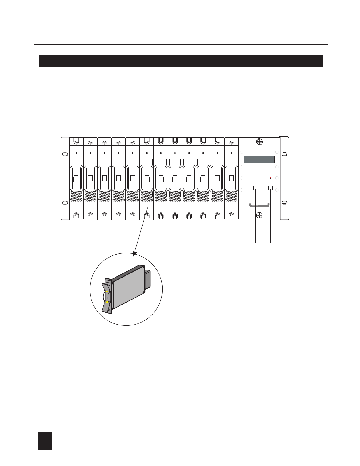
1. Overview
1.1 Front View
3
DMX
MENU UP
DOWN
ESC
Channel dimmer module
1
2
3
4
5
6
7
Page 7

1. Overview
1. 2x16 LCD Display
Shows the current activities or adjustments of menus.
1.1 Front View
4
2. DMX LED
This LED blinks when DMX signal is present.
3. MENU Button
This button is used to access set-up menus.
4. UP Button
Tap this button to scroll through menus or to increase values .
5. DOWN Button
Tap this button to scroll through menus or to decrease values .
6. ESC Button
Tap this button to go back last menu level or to leave menu system.
7. Channel Dimmer Module(x12)
The channel dimmer module is incorporated with a 10A circuit breaker
and SCRs with 1000A peak current capacity. The removable, plug &
play module enables easy and flexible setup of 12 channel module.
Page 8

1. Overview
1.2 Rear View
5
1. Analogue Input
DC 0-10V
2. DMX Input
This jack is used to receive an incoming DMX signal..
3. DMX Output
This jack is used to send DMX signal to next DMX device
or link to another unit.
23-001-1518
DMX IN
DMX OUT
1 : Ground
2 : Data 3 : Data +
Analog in: 0~10VDC
1
8
9
15
3
2
3
2
1
2
3
Page 9

1. Overview
6
1.3 Mains power & Output Termination
Page 10

2. Operation Guide
2.1 Display and standby mode
7
Power on this unit, the LCD shows the revision of software immediately, then
enter standby mode automatically, the LCD shows the dimming level of each
channel as below. The first row indicates the dimming level, and the second
row indicates the channel(1 stands for channel 1, 2 stands for channel 2, and
so on. A, B and C stand for channel 10, 11 and 12.).
2.2 Set-up Menus
MENU UP DOWN ESC
In standby mode, tap MENU button to
enter set-up menus .
There are 6 menus: DMX Fail, Phase
Correction, DMX Address, Preheat, curve
and Preset , you can use UP/DOWN button
to scroll through the menus.
Tap ESC button to leave set-up menus
system.
Dmx fail
1 2 3 4 5 6 7 8 9 A B C
2.2.1 DMX Fail
MENU UP DOWN ESC
1. Tap UP/DOWN button to scroll to DMX
Fail menu.
Dmx fail
Page 11

2. Operation Guide
8
2.2.1 DMX Fail
MENU UP DOWN ESC
2. Tap MENU button again to enter sub-menu
system. You can use UP/DOWN button
to select Hold/Analog/Prog. 1-12.
[Hold]: Last received DMX signal is held.
[Analog]: The analogue input(0-10v) is activated.
[Prog. 1-12]: Starts internal programs 1-12.
3. If you select Hold or Analog, you can tap ESC
button to exit.
MENU UP DOWN ESC
Dmx fail
Hold
Dmx fail
Analog
4. If you select Prog. 1-12, tap ESC button, speed
menu will be activated.
You can select the chasing speed from 0.1 to
20 seconds using UP/DOWN button.
After you've finished your setting, tap ESC
button to exit.
MENU UP DOWN ESC
Speed
00.4s
MENU UP DOWN ESC
Speed
02.4s
Page 12

2. Operation Guide
9
2.2.2 Phase Correction
MENU UP DOWN ESC
1. Tap UP/DOWN button to scroll to Phase
Correction menu.
Pha corr
MENU UP DOWN ESC
2. Tap MENU button to enter sub-menu
system. You can use UP/DOWN button
to select Yes/No.
Pha corr
Yes
[Yes]: Linear dimming is activated.
[No]: Non-linear dimming is activated.
MENU UP DOWN ESC
3. Tap ESC button to exit.
Pha corr
Yes
2.2.3 DMX Address
MENU UP DOWN ESC
1. Tap UP/DOWN button to scroll to DMX
Address menu.
Dmx addr
Page 13

2.2.3 DMX Address
2. Operation Guide
10
MENU UP DOWN ESC
2. Tap MENU button to enter sub-menu
system. You can use UP/DOWN button
to select Block/Single.
Block
[Block]: Complete dimmer(6 channels) has only
one start address.
[Single]: The DMX address of each channel is
selectable, several channels can select
the same DMX addresses.
Dmx addr
MENU UP DOWN ESC
3. Tap UP/DOWN button to scroll to Block/Single menu, and tap MENU to
enter Block/Single mode.
Block
Dmx addr
4.
In Block mode, you can use UP/DOWN button
to select the start address from [001-512].
MENU UP DOWN ESC
[001]
Start
MENU UP DOWN ESC
[001]
Start
+
Page 14

2. Operation Guide
2.2.3 DMX Address
11
5.
In Single mode, tap MENU to change between
the channel and its address.
MENU UP DOWN ESC
[001]
Chan[1]
6. When channel is activated, tap UP/DOWN
button to select from [1-12]; when address is
activated, tap UP/DOWN button to select
from[001-512].
MENU UP DOWN ESC
[001]
Chan[1]
7.
Tap ESC button to exit.
MENU UP DOWN ESC
Dmx addr
2.2.4 Preheat
MENU UP DOWN ESC
1. Tap UP/DOWN button to scroll to Preheat
menu.
Preheat
Page 15

2. Operation Guide
2.2.4 Preheat
12
MENU UP DOWN ESC
2. Tap MENU button to enter sub-menu
system.
All
Preheat
MENU UP DOWN ESC
3. Tap UP/DOWN button to select between All/Single mode, and tap MENU
to enter All/Single mode.
All
Preheat
MENU UP DOWN ESC
[000%]
All
+
MENU UP DOWN ESC
4. In All mode, tap UP/DOWM to select preheat
value of all channels between 000%-050%.
[000%]
All
MENU UP DOWN ESC
5. In Single mode, tap MENU to select between
channel and preheat value.
[000%]
Chan[1]
Page 16

2. Operation Guide
2.2.4 Preheat
13
6. When channel is activated, tap UP/DOWN
button to select from [1-12]; when preheat is
activated, tap UP/DOWN button to select
from [000%-050%].
MENU UP DOWN ESC
[050%]
Chan[1]
7.
Tap ESC button to exit.
MENU UP DOWN ESC
Preheat
2.2.5 Curve
MENU UP DOWN ESC
1. Tap UP/DOWN button to scroll to Curve
menu.
Curve
MENU UP DOWN ESC
2. Tap MENU button to enter sub-menu
system.
Linear
Curve
Page 17

2. Operation Guide
2.2.5 Curve
14
MENU UP DOWN ESC
3. Tap UP/DOWM button to select from Linear/
Switch/Square.
Linear
Curve
MENU UP DOWN ESC
4. Tap ESC button to exit.
Curve
5. You can tap ESC button to return to
Beginning Menu.
MENU UP DOWN ESC
1 2 3 4 5 6 7 8 9 A B C
2.2.6 Preset
MENU UP DOWN ESC
1. Tap UP/DOWN button to scroll to Preset
menu.
Preset
This menu allows you to control the dimmer of all
channels or individual channel.
Page 18

15
MENU UP DOWN ESC
2. Tap MENU button to enter sub-menu
system.
All
Preset
MENU UP DOWN ESC
3. Tap UP/DOWN button to select between All/Single mode, and tap MENU
to enter All/Single mode.
All
Preset
MENU UP DOWN ESC
[000%]
All
+
MENU UP DOWN ESC
4. In All mode, tap UP/DOWM to adjust the master
dimming level from 000%-100%.
[000%]
All
MENU UP DOWN ESC
5. In Single mode, tap MENU to change between
the channel and its dimming level.
[000%]
Chan[1]
2. Operation Guide
2.2.6 Preset
Page 19

Power Input ......................................................... AC 120V~50/60Hz
Channel Output(Single phase).......................... 10A/CH., Total 120A
Channel Output(Three phases)................................ 10A/CH., 3x40A
DMX Output ............................................... 3 pin female XLR socket
DMX Input ..................................................... 3 pin male XLR socket
Analogue Input ................................... 0-10V, 15-pin sub DIN socket
Dimensions ............................................................ 482x390x160mm
Weight(appro.) ...................................................................... 20.8 Kg
16
2. Operation Guide
6. When channel is activated, tap UP/DOWN
button to select from [1-12]; when dimming
level is activated, tap UP/DOWN button to
select from [000%-100%].
MENU UP DOWN ESC
[050%]
Chan[1]
7.
Tap ESC button to exit.
MENU UP DOWN ESC
Preset
2.2.6 Preset
Technical Specifications
Page 20

Rev 1.0 October 2002
Printed in PR China
24-004-0892
All Rights Reserved
 Loading...