

Page 1

CLARITY
Lighting and Media Control
OPERATOR MANUAL
Issue 2.01
Desktop (MAC/PC)
LX300
LX600
LX900
Covering software Version 2
May 2013
Document number: LX-T01U-A2
LSC Lighting Systems (Aust) Pty. Ltd.
ABN 21 090 801 675
Building 3, 66-74 Micro Circuit
Dandenong South, Victoria 3175 Australia
Tel: +61 3 9702 8000 Fax:+61 3 9702 8466
email: info@lsclighting.com
web: www.lsclighting.com
Page 2

DISCLAIMER
Both LSC Lighting Systems (Aust) Pty. Ltd. and OpenClear Pty. Ltd. have a corporate policy of
continuous improvement, covering areas such as product design and documentation. To achieve this
goal, we undertake to release software updates for all products on a regular basis. In light of this
policy, some detail contained in this manual may not match the exact operation of your product.
Information contained in this manual is subject to change without notice.
In any event, neither LSC Lighting Systems (Aust) Pty. Ltd. nor OpenClear Pty. Ltd. can be held
liable for any direct, indirect, special, incidental, or consequential damages or loss whatsoever
(including, without limitation, damages for loss of profits, business interruption, or other pecuniary
loss) arising out the use or the inability to use this product for its intended purpose as expressed by
the manufacturer and in conjunction with this operating manual.
Servicing of this product is recommended to be carried out by LSC Lighting Systems (Aust) Pty. Ltd.
or its authorized service agents. No liability will be accepted whatsoever for any loss or damage
caused by service, maintenance or repair by unauthorized personnel.
In addition servicing by unauthorized personnel may void your warranty.
LSC Lighting Systems’ products must only be used for the purpose for which they were intended.
Clarity LX products are manufactured in Australia.
Page 3

Clarity
Contents
Operator Manual
Contents
1 Latest Features 1
1.1 Overview _________________________ 1
1.2 Version 2 _________________________ 1
1.2.1 Rig Mode __________________________ 1
1.2.2 OSC ______________________________ 1
1.2.3 Page Bookmarks ____________________ 1
1.2.4 User Definable Keyboard Shortcuts _____ 1
1.2.5 Date/Time Scheduler. ________________ 1
1.2.6 Audio Control Device _________________ 1
1.2.7 Intensity Levels windows _____________ 1
1.2.8 Touch Screen Input Support ___________ 1
1.2.9 Touch Mode ________________________ 2
1.2.10 Redesigned Record Dialogue Box _______ 2
1.2.11 Out Timing ________________________ 2
1.2.12 Console Emulation __________________ 2
1.2.13 Show Files _________________________ 2
1.2.14 New User preferences ________________ 2
1.2.15 New Cue-list Options _________________ 2
1.2.16 Minor Changes _____________________ 3
1.2.17 Fixture Attribute Default Values ________ 3
1.2.18 MAC Installation ____________________ 3
1.2.19 User Manual _______________________ 3
2 Introduction/Models 4
2.1 Overview _________________________ 4
2.2 Desktop Version ____________________ 4
2.3 Console Models ____________________ 4
2.4 Common Features __________________ 4
2.5 Help _____________________________ 5
3 Desktop (PC or MAC) Clarity 6
3.1 Overview _________________________ 6
3.1.1 Software __________________________ 6
3.2 Installing Clarity on a PC _____________ 6
3.3 Installing Clarity on a Mac ____________ 8
3.3.1 HASP Installation for Mac _____________ 8
3.4 HASP Diagnostics ___________________ 8
3.5 Demo Mode _______________________ 8
3.6 Desktop DMX Output ________________ 9
3.7 Desktop ArtNet Output ______________ 9
3.8 VX10 Playback Wing ________________ 9
3.9 VX20 Programming & Playback Wing __ 10
3.9.1 USB Indicator _____________________ 10
3.9.2 DMX Indicators ____________________ 10
3.9.3 Desklamp ________________________ 10
3.9.4 Kensington Lock Slot ________________ 10
3.9.5 USB Slot _________________________ 10
3.10 Starting Clarity ____________________ 11
3.11 Loading a Show ___________________ 11
3.11.1 Show Tab ________________________ 11
3.12 Modes Of OPeration ________________ 12
3.12.1 Console Window ___________________ 13
3.13 Basic Desktop Operation ____________ 15
3.14 Patching _________________________ 16
3.15 Programming _____________________ 17
3.15.1 Attribute Controls __________________ 17
3.15.2 Attribute Quick Menus _______________ 18
3.15.3 Universal Controller_________________ 18
3.15.4 Creating a Lighting Look _____________ 18
3.16 Playback _________________________ 19
3.16.1 Control Booth _____________________ 19
3.16.2 Adding a Virtual VX Wing ____________ 19
3.16.3 Selecting a Virtual VX Wing __________ 19
3.17 Adding a Cue-list to a VX Wing _______ 20
3.18 Wing Playback Pages _______________ 20
3.18.1 Locking a Playback __________________ 21
3.18.2 Page Bookmarks ___________________ 21
3.18.3 Managing VX Pages _________________ 21
3.19 Wing Playbacks ____________________ 21
3.20 Wing Group Masters ________________ 22
3.21 Extended Wing Controls _____________ 23
3.22 Programming with the VX20 Wing _____ 25
3.22.1 Trackball _________________________ 25
3.22.2 Programmer Buttons ________________ 25
3.22.3 VX20 Soft Menus ___________________ 26
3.23 External Control Inputs ______________ 27
3.24 VX20 MIDI _______________________ 27
3.25 Desklamp Intensity _________________ 28
3.26 Free Mode ________________________ 28
4 LX Consoles 29
4.1 Overview _________________________ 29
5 LX300 Console 30
5.1 Overview _________________________ 30
5.2 LX300 Rear Panel __________________ 30
5.2.1 Power Input and Mains Switch _________ 31
5.2.2 DMX Outputs ______________________ 31
5.2.3 Ethernet __________________________ 31
5.2.4 DVI Video Out _____________________ 31
5.2.5 USB _____________________________ 31
5.2.6 MIDI _____________________________ 31
5.2.7 Audio In/Out ______________________ 31
5.2.8 LED Desk Lamps ___________________ 31
5.2.9 External Inputs ____________________ 31
5.2.10 Reset ____________________________ 32
5.4 LX300 Front Panel __________________ 33
5.4.1 LX300 Playbacks ___________________ 33
6 LX600 Console 35
6.1 Overview _________________________ 35
6.2 LX600 Rear Panel __________________ 36
6.2.1 Power Input and Mains Switch _________ 36
6.2.2 Mains Outputs _____________________ 36
6.2.3 DMX Outputs ______________________ 36
6.2.4 Ethernet __________________________ 36
6.2.5 DVI Video Out _____________________ 36
6.2.6 USB _____________________________ 37
6.2.7 MIDI _____________________________ 37
6.2.8 SPMTE Timecode ___________________ 37
6.2.9 Audio In/Out ______________________ 37
6.2.10 LED Desk Lamps ___________________ 37
6.2.11 External Inputs ____________________ 37
6.2.12 Reset ____________________________ 37
6.4 LX600 Front Panel __________________ 38
7 LX900 Console 39
7.1 Overview _________________________ 39
7.2 LX900 Rear Panel __________________ 39
7.2.1 Power Input and Mains Switch _________ 40
7.2.2 Mains Outputs _____________________ 40
7.2.3 DMX Outputs ______________________ 40
7.2.4 DMX Input ________________________ 40
7.2.5 Ethernet __________________________ 40
7.2.6 DVI Video Out _____________________ 40
7.2.7 USB _____________________________ 40
7.2.8 MIDI _____________________________ 40
7.2.9 SPMTE Timecode ___________________ 40
7.2.10 Audio In/Out ______________________ 40
Page 4

Contents
Clarity
Operator Manual
7.2.11 LED Desk Lamps ___________________ 41
7.2.12 External Inputs ____________________ 41
7.2.13 Reset ___________________________ 41
7.4 LX900 Front Panel __________________ 42
7.5 LX900 Split Cross Fade ______________ 42
8 LX Console Controls 44
8.1 Overview _________________________ 44
8.2 Power Switches ____________________ 44
8.3 Grand Master _____________________ 44
8.4 Encoder Wheel Touch Screen _________ 44
8.4.1 Trackpad Mode ____________________ 45
8.5 Encoder Wheels and Buttons _________ 46
8.5.1 Rig _____________________________ 47
8.5.3 Universal _________________________ 48
8.5.4 Direct ___________________________ 49
8.5.5 Expand __________________________ 49
8.5.6 Virtual Wheels _____________________ 49
8.5.7 Intensities ________________________ 50
8.5.8 Graphical ________________________ 50
8.5.9 Timing ___________________________ 51
8.5.10 Dynamics ________________________ 52
8.5.11 Matrix ___________________________ 52
8.5.12 Media ___________________________ 52
8.5.13 Palettes __________________________ 52
8.6 Keypad and Command Centre ________ 53
8.6.1 User Buttons ______________________ 53
8.6.2 Intensity Wheel ___________________ 53
8.6.3 Numeric Keypad ___________________ 53
8.6.4 Command Centre __________________ 53
8.7 Playbacks ________________________ 55
8.7.1 LX300 Button Playbacks _____________ 55
8.7.2 Fader Playbacks ___________________ 56
8.7.3 Playback Controls __________________ 56
8.7.4 Playback Touch Screens _____________ 57
8.7.5 Assign or Clear a Playback ___________ 57
8.7.6 Configuring a Playback ______________ 57
8.7.7 Playback Pages ____________________ 58
8.7.8 Locking a Playback _________________ 59
8.7.9 Managing Pages ___________________ 59
8.7.10 Page Bookmarks ___________________ 59
8.7.11 Page Groups ______________________ 60
8.7.12 Extended Playback Controls __________ 60
8.7.13 Releasing a Playback _______________ 62
8.7.14 Releasing ALL Playbacks _____________ 62
8.7.15 Clearing a Playback ________________ 62
8.7.16 Edit _____________________________ 62
8.7.17 Group Masters ____________________ 62
8.7.18 Playback Contents Indicator __________ 63
8.8 Action Buttons ____________________ 64
8.8.1 Action Button Pages ________________ 64
8.8.2 Assigning an Action Button ___________ 64
8.8.3 Clearing an Action Button ____________ 65
8.9 Touch Screen(s) ___________________ 65
9 Basic Operation 67
9.1 Overview _________________________ 67
9.2 Patching _________________________ 67
9.3 Programming _____________________ 68
9.4 Playback _________________________ 68
9.4.1 Performance Window _______________ 68
10 Customizing Clarity 69
10.1 Overview _________________________ 69
10.2 LX Tools _________________________ 69
10.3 Touch Screen Operation _____________ 69
10.4 Dockable Windows _________________ 69
10.5 Resizing Panes ____________________ 69
10.6 Rig Mode Icons ____________________ 69
10.7 Universal and Direct _______________ 69
10.8 Attribute Control Size ______________ 69
10.9 Preferences ______________________ 71
10.10 Keyboard Shortcuts ________________ 71
11 Patching Fixtures 73
11.1 Overview ________________________ 73
11.2 Spreadsheet View _________________ 74
11.3 Patching Fixtures __________________ 74
11.3.1 Drag and Drop Patching _____________ 74
11.3.2 Patching Dimmers __________________ 74
11.3.3 Clarity Universes ___________________ 74
11.4 Clone from other fixture(s) __________ 75
11.4.1 Cloning Example ___________________ 76
11.5 Keypad Patching __________________ 76
11.5.1 Patching Commands: ________________ 76
11.6 Multi-Patch _______________________ 76
11.6.1 Keypad Multi-Patch _________________ 76
11.6.2 Copy Multi-Patch ___________________ 77
11.6.3 Removing Multi-Patches _____________ 77
11.7 Selecting Fixtures _________________ 77
11.8 Inverting/Swapping Attributes ________ 77
11.9 Intensity Fade Profiles ______________ 78
11.10 Minimum and Maximum Intensity _____ 79
11.11 Custom Fixtures ___________________ 80
11.12 Connecting Output Devices __________ 80
11.13 Configuring ArtNet Outputs __________ 80
11.14 Editing the Patch __________________ 80
11.14.1 Editing a Fixtures Address ____________ 81
11.14.2 Editing a Fixtures Name or Number ____ 81
11.14.3 Deleting Fixtures ___________________ 81
11.14.4 Un-Patching Fixtures ________________ 81
11.14.5 Exporting the Patch _________________ 81
12 Rig 82
12.1 Overview ________________________ 82
12.2 Arranging Fixtures _________________ 82
12.3 Aligning Fixtures __________________ 83
12.4 Fixture Icons _____________________ 83
12.5 Multiple Views ____________________ 84
12.5.1 Creating a new View ________________ 84
12.6 Configuring a View _________________ 84
12.6.1 Background Image _________________ 85
12.7 Selecting Fixtures In Rig View ________ 85
13 Universal 87
13.1 Overview ________________________ 87
13.2 Universal Mode Pages ______________ 87
14 Direct 89
14.1 Overview ________________________ 89
15 Intensities 90
15.1 Overview ________________________ 90
15.2 Channel Controller Mode ____________ 90
15.2.1 Settings for Channel Controller Mode ___ 91
15.2.2 Operating in Channel Controller Mode ___ 91
16 Timing 92
16.1 Overview ________________________ 92
16.2 Cuelist Times _____________________ 92
16.3 Cue Times _______________________ 92
16.3.1 Intensity Fade Out times. ____________ 92
16.4 Cue Attribute Times ________________ 93
16.4.1 Timing Mode ______________________ 93
Page 5

Clarity
Contents
Operator Manual
16.4.2 Timing Tab _______________________ 93
16.5 Setting Times _____________________ 94
16.5.1 Setting Times by Direct Entry _________ 94
16.6 Fade Curves ______________________ 95
16.7 Filtering Times ____________________ 95
16.7.1 Combining Filters __________________ 96
16.7.2 Complex Timing ___________________ 97
16.8 Previewing Times __________________ 97
16.9 Recording Times __________________ 97
16.10 Reset Timing _____________________ 97
16.11 Time Presets _____________________ 97
16.11.1 Recording Time Presets ______________ 97
16.11.2 Applying Time Presets _______________ 98
17 Dynamics (real time effects) 99
17.1 Overview ________________________ 99
17.2 Applying Dynamics ________________ 99
17.3 Controlling Dynamics ______________ 100
17.3.1 Waveform Control _________________ 100
17.3.2 Dynamics Attribute Controls _________ 101
17.4 Multiple Attribute Dynamics _________ 101
17.4.1 Stopping Dynamics ________________ 102
17.4.2 Resync __________________________ 102
17.4.3 Attribute Control Dynamics Indicators _ 102
18 Matrix 103
18.1 Overview _______________________ 103
18.2 Terminology _____________________ 103
18.3 Patching a LED Matrix _____________ 103
18.4 Creating a Matrix _________________ 103
18.5 Editing a Matrix __________________ 104
18.5.1 Deleting a Matrix __________________ 104
18.6 Matrix Control ___________________ 105
18.7 Transforms ______________________ 105
18.8 Adding Media to a Pixel Source ______ 106
18.9 Selecting Media in a Pixel Source ____ 106
18.10 Adding and Deleting Pixel Sources ___ 107
18.11 Viewer _________________________ 107
18.12 Activating a PixelSource ___________ 107
18.13 Activating Selected Cells ___________ 108
18.14 Pixel Source Layering and Transparency108
18.15 PixelSource Transitions ____________ 108
18.16 Dynamics _______________________ 108
18.17 Recording Matrix Settings __________ 109
19 Media 110
19.1 Overview _______________________ 110
19.2 Patching Media servers ____________ 110
19.3 Network Connection _______________ 110
19.4 Configuration ____________________ 110
19.4.1 Reload __________________________ 110
19.5 Media Server Operation ____________ 110
19.5.1 Browser _________________________ 111
19.5.2 Controls _________________________ 111
19.6 Recording Cues __________________ 111
19.7 Supported Media Servers ___________ 112
20 Palettes 113
20.1 Overview _______________________ 113
20.2 Arranging Palettes and Groups ______ 114
20.3 Groups _________________________ 114
20.4 Colour Presets ___________________ 114
20.5 Beam Presets ____________________ 115
20.6 Favourites ______________________ 115
20.7 Presets _________________________ 115
20.7.1 Fixture Specific Presets _____________ 116
20.7.2 Fixture Type Presets _______________ 116
20.8 Freesets ________________________ 116
20.8.1 Permutating Freesets _______________ 116
20.8.2 Scaling Freesets ___________________ 116
20.9 Dynamic Presets __________________ 117
20.10 Recording a Preset or Freeset ________ 117
20.11 Palette Icons _____________________ 118
20.11.1 Group Icons ______________________ 118
20.11.2 Preset & Freeset Icons ______________ 118
20.11.3 Preset and Freeset Shortcuts _________ 118
20.12 Applying Presets and Freesets _______ 119
20.12.1 Keyboard Commands _______________ 119
20.12.2 Apply in Palettes Mode ______________ 119
20.12.3 Apply in the Palettes window _________ 120
20.12.4 Build Mode _______________________ 120
20.12.5 Live Times _______________________ 120
20.12.6 Apply Palettes in the Programmer window121
20.12.7 Masking _________________________ 121
20.13 Applying Dynamic Presets __________ 122
20.13.1 Masking Dynamic Presets ___________ 122
20.13.2 Base ____________________________ 122
20.13.3 Preserve Dynamics _________________ 123
20.14 Controlling Dynamics ______________ 123
20.15 Deactivate a Preset or Freeset _______ 123
20.16 Recording Cues with Presets & Freesets.124
20.17 Updating a Preset During Programming 124
20.18 Updating a Preset During Playback ____ 124
21 Programmer 126
21.1 Overview ________________________ 126
21.2 Programmer Attributes Tab _________ 126
21.3 Selection Sidebar _________________ 127
21.4 Selecting Fixtures _________________ 127
21.4.1 Selection phase vs. Programming phase 127
21.4.2 Selecting Multiple Types of Fixtures ____ 127
21.4.3 Deselecting Fixtures ________________ 127
21.4.4 Selection Order ___________________ 128
21.4.5 Attribute Quick Menus ______________ 128
21.4.6 Programmer Toolbar Fixture Buttons ___ 128
21.5 Individual Fixture Control ___________ 129
21.6 Groups _________________________ 129
21.6.1 Editing Groups ____________________ 129
21.6.2 Sort ____________________________ 130
21.6.3 Subgroups _______________________ 130
21.6.4 Buddying ________________________ 130
21.6.5 Ctrl Tab _________________________ 131
21.6.6 Intensity and Colour Icons ___________ 131
21.6.7 Position Icons _____________________ 131
21.7 Session Control ___________________ 132
21.7.1 Altered Fixture Indication ____________ 132
21.7.2 Blind Programming_________________ 133
21.7.3 Clearing a Programmer _____________ 133
21.7.4 Clearing a Fixture from a Programmer _ 133
21.7.5 Clearing an Attribute from a Programmer133
21.8 Programmer Toolbar _______________ 133
21.8.1 Undo / Redo ______________________ 133
21.8.2 None, Prev, All, Next _______________ 133
21.8.3 Grab ____________________________ 134
21.8.4 Preview _________________________ 134
21.8.5 To Preset ________________________ 134
21.8.6 Record/Save ______________________ 134
21.8.7 Append last/Save As _______________ 134
21.8.8 Update __________________________ 134
21.8.9 Highlight _________________________ 136
21.8.10 Highlight and Lowlight settings _______ 136
21.8.11 Blind ____________________________ 136
21.8.12 Clear/Close _______________________ 136
21.9 Programmer Toolbox ______________ 137
21.9.1 Show Undo View __________________ 137
21.9.2 Trim (knock out remainder) __________ 137
Page 6

Contents
Clarity
Operator Manual
21.9.3 Remainder Dim ___________________ 137
21.9.4 Controls ________________________ 137
21.9.5 Renumber Fixtures ________________ 137
21.9.6 Grab DMX _______________________ 137
21.9.7 Copy ___________________________ 137
21.9.8 Paste ___________________________ 137
21.9.9 Flip ____________________________ 138
21.9.10 Personalizing the Toolbar ___________ 138
21.10 DMX Input _______________________ 138
21.11 Parking Fixtures __________________ 138
21.12 Universal Control Panel _____________ 139
21.13 Attribute Controls _________________ 139
21.13.1 Attribute Quick Menus _____________ 139
21.13.2 Fixture Quick Menus _______________ 140
21.13.3 Attribute Control Size ______________ 140
21.13.4 Attribute Control Order _____________ 141
21.14 Fanning Attributes ________________ 141
21.14.1 Offset Fanning ___________________ 141
21.14.2 Fanning Selection Order ____________ 141
21.14.3 Fanning in the Universal Control Panel _ 142
22 Command Line Programming 143
22.1 Overview ________________________ 143
22.2 Fixture Selection __________________ 143
22.3 Intensity Entry ___________________ 143
22.4 Intensity Wheel ___________________ 144
22.5 Fade Time Entry __________________ 144
22.6 Fixture Numbering for Keypad Entry __ 144
22.6.1 Changing Fixture Unit Numbers ______ 144
23 Record 145
23.1 Overview ________________________ 145
23.2 Recording a Cue __________________ 145
23.2.1 New Cue-list _____________________ 145
23.2.2 Cue-list Playback Settings and Options 146
23.2.3 Cue Options _____________________ 146
23.2.4 Existing Cue-list __________________ 146
23.2.5 Contents Options _________________ 147
23.2.6 Keep Settings ____________________ 148
23.2.7 Clear recorded values ______________ 148
23.3 Editing Cues _____________________ 148
23.3.1 Undo Redo ______________________ 149
24 Control Booth 150
24.1 Overview ________________________ 150
24.2 Cue-list Playback Settings __________ 150
24.2.1 Cue-list Playback Options ___________ 151
24.2.2 Cue-list Chase Options _____________ 154
24.2.3 Cue-list Priority Settings ____________ 155
24.3 Playback Control Panel _____________ 155
24.4 Manipulating cues and cue-lists ______ 156
24.4.1 Cue-list Folders ___________________ 156
24.4.2 Copying and Merging Cues __________ 156
24.4.3 Copy Full State ___________________ 157
24.4.4 Undo Redo ______________________ 157
24.4.5 Cue Notes _______________________ 158
24.5 Sync FX _________________________ 158
24.6 Mark Cues (Move in Black) __________ 158
24.7 Audio Playback ___________________ 159
24.7.1 Audio Fixture ____________________ 160
24.8 Simple SCRIPT language (Macros) ____ 160
24.9 Learn new cue-list_________________ 161
24.10 Bookmark _______________________ 162
25 Editing Cues and Cue-lists 163
25.1 Overview ________________________ 163
25.2 Editing a Cue _____________________ 163
25.3 Editing Follow or Wait Times ________ 163
25.3.1 Saving the Edit ___________________ 165
25.4 Editing Channels to be “Cue Only” ___ 165
25.4.1 “Cue Only” Indication ______________ 165
25.5 Live Edit Indication _______________ 166
25.6 Block Cue _______________________ 166
25.7 Undo Redo Edits _________________ 166
25.8 Exporting a Cue to the Programmer __ 166
26 Performance Window 167
26.1 Overview _______________________ 167
26.2 Previewing Cue-lists _______________ 168
26.3 The Grid ________________________ 168
26.4 Adapting Existing Programming _____ 168
26.4.1 Sync FX _________________________ 168
26.5 Managing the Grid ________________ 169
26.5.1 Copying Active Cells to a Common Row 169
26.5.2 Cell Properties ____________________ 169
26.6 The Metronome __________________ 171
26.6.1 Metronome Settings _______________ 172
26.7 Performance Freesets/Groups _______ 172
27 Levels Window 173
27.1 Overview _______________________ 173
27.2 DMX Values _____________________ 173
27.3 Output Values ___________________ 173
27.4 Programmer Values _______________ 174
27.5 Cue List Values __________________ 174
27.6 Customizing The Display ___________ 174
27.7 New Window ____________________ 174
28 Intensity Levels 175
28.1 Overview _______________________ 175
28.2 View Setings ____________________ 175
28.3 Console View ____________________ 176
28.4 Follow View _____________________ 176
29 Show Files and Packages 177
29.1 Overview _______________________ 177
29.2 Saving and Loading Shows _________ 177
29.3 Importing and Exporting Shows _____ 177
29.4 Desktop Clarity local Media libraries __ 177
30 MIDI 179
30.1 Overview _______________________ 179
30.2 MIDI Control of Selected Playback ___ 179
30.2.1 MIDI Settings ____________________ 179
30.2.2 MIDI Channel _____________________ 179
30.2.3 MIDI Note On Messages ____________ 179
30.2.4 MIDI Control Function ______________ 180
30.2.5 Learn Midi _______________________ 180
30.3 MIDI Timecode ___________________ 180
30.3.1 Automatic Entry of Events ___________ 181
30.3.2 Manual Entry of Events _____________ 181
30.3.3 Editing Events ____________________ 181
30.3.4 Managing Playlists _________________ 182
30.3.5 MIDI Timecode Playback ____________ 182
30.3.6 Recede __________________________ 182
30.3.7 Skip Intervening Events ____________ 182
30.3.8 Big Time ________________________ 182
30.3.9 Simulator ________________________ 182
31 Remote Control 184
31.1 Overview _______________________ 184
31.2 Controlling Clarity via an IPhone _____ 184
Page 7

Clarity
Contents
Operator Manual
31.2.1 Setting up OSC on an iPhone ________ 184
31.2.2 Setting up OSC on Clarity ___________ 184
31.2.3 Controlling Clarity with OSC _________ 185
31.3 Controlling Other Devices From Clarity 186
32 Scheduler 187
32.1 Overview _______________________ 187
32.2 Schedule an Event ________________ 187
33 Tracking Backup 188
33.1 Overview _______________________ 188
33.2 Setting up Tracking Backup _________ 188
33.3 Operating From The Slave __________ 189
34 Preferences and About 190
34.1 User Preferences _________________ 190
34.1.1 New Show Preferences _____________ 193
34.2 About Clarity ____________________ 194
35 LX Tools 195
35.1 Overview _______________________ 195
35.2 Starting LX Tools _________________ 195
35.2.1 Brightness _______________________ 195
35.2.2 Software Management _____________ 196
35.2.3 Help ____________________________ 196
35.2.4 Configure Monitors ________________ 196
35.2.6 Networking ______________________ 197
35.2.7 Calibrate Touch Screens ____________ 198
35.2.8 Clock ___________________________ 198
35.2.9 Diagnostics ______________________ 198
35.2.10 System Information _______________ 198
35.2.11 Keyboard ________________________ 198
36 Software Upgrade 199
36.1 Overview _______________________ 199
36.2 Desktop Upgrade _________________ 199
36.3 LX Console Upgrade _______________ 199
37 Technical Support 200
38 Fixture Editor 201
38.1 Overview _______________________ 201
38.2 Fixture Request Service ____________ 201
38.3 Fixture Editor ____________________ 201
39 Operating Concepts and
Terminology 202
39.1 Overview _______________________ 202
39.2 Programmer / Playback ____________ 202
39.3 Priority Control ___________________ 202
39.4 Attribute Default Values ____________ 202
39.5 Programmer Control _______________ 202
39.6 Playback Control __________________ 203
39.7 Recording and Playback Concepts ____ 203
39.7.1 Tracking Playback _________________ 203
39.7.2 Typical Tracking Operations __________ 203
39.7.3 Advantages of Tracking _____________ 204
39.7.4 Disadvantages of Tracking ___________ 204
39.7.5 Cue Only Playback _________________ 205
39.8 Recording Cues ___________________ 205
39.8.1 Content Options ___________________ 206
39.8.2 Cue Only (recording) _______________ 207
39.8.3 Mark Cues (Move in Black) __________ 208
39.9 DMX 512 ________________________ 208
39.10 DMX Universes ___________________ 208
39.10.1 DMX Slot ________________________ 208
39.10.2 Attribute. ________________________ 208
39.11 HTP (HIGHEST TAKES PRECEDENCE) __ 208
39.12 LTP (LATEST TAKES PRECEDENCE) ___ 208
39.13 RDM ___________________________ 208
40 Hints and Tips 210
40.1 Simple Cue Playback _______________ 210
40.2 Parked channels __________________ 210
40.3 One Shot Chase __________________ 210
40.4 Performance Window Tips___________ 210
40.5 Flashing a cue ____________________ 211
40.6 Quick Record _____________________ 211
40.7 Snapping Forwards or Backwards _____ 211
40.8 Operate Clarity Like a Manual Desk ___ 211
40.9 Programmer Override ______________ 211
40.10 Media Server Thumbnails ___________ 211
40.11 Audio Playback ___________________ 212
40.12 Automated Follow Spot Audio Cues ___ 212
40.13 Simple RGB Mixing ________________ 212
40.14 Recording Only Pan (or Tilt) _________ 213
40.15 Time Presets _____________________ 213
40.16 Sorting, Buddying & SubGroups ______ 213
40.17 Universal Control. _________________ 213
40.18 Copy And Paste ___________________ 213
40.19 Fans Buttons _____________________ 214
40.20 Multiple Programmers ______________ 214
40.21 Cuelist Folder Order _______________ 214
41 Index 215
42 COMPLIANCE STATEMENTS 218
Page 8

Clarity
Operator Manual
Conventions Used in this Manual
Throughout this manual, certain conventions have been used to make the meaning clearer.
1) A word in Bold test represents a button, a Tab, an area or label on the GUI (Graphical User
Interface).
2) The terms “Click” “Select” and “Touch” are interchangeable.
3) Emphasis is indicated by underlining.
4) Notes or Hints are displayed in italic font
Copyright Notices
Clarity application software is developed by OpenClear Pty. Ltd.
www.openclear.com.au
Copyright © 2009 OpenClear Pty. Ltd.
All rights reserved.
USB and RDM software modules and LX products are developed by LSC Lighting Systems (Aust) Pty. Ltd.
www.lsclighting.com
Copyright © 2009 LSC Lighting Systems (Aust) Pty. Ltd.
All rights reserved.
Contents of this manual, Copyright © 2012
OpenClear Pty. Ltd. and LSC Lighting Systems (Aust) Pty. Ltd.
All rights reserved.
Page 9

Clarity
Latest Features
Operator Manual
Page 1
1 Latest Features
1.1 OVERVIEW
Both LSC Lighting Systems (Aust) Pty. Ltd. and OpenClear Pty. Ltd. have a corporate policy of
continuous improvement covering areas such as product design and documentation. To achieve
this goal, we undertake to release software updates for all products on a regular basis. The latest
features to be added to this version of Clarity are listed below.
1.2 VERSION 2
Clarity Version 2 contains the following new or enhanced features.
1.2.1 Rig Mode
Rig mode is a fixture selection tool and two dimensional visualiser. It shows a geographical view
of the patched fixtures (and groups) which you can arrange so that they are positioned as they
actually are in your rig. This allows you to rapidly find and select fixtures for programming by
clicking on them or touching them. A background image of your stage or venue can be added to
aid selection and multiple views can be created. The intensity, colour and position of the fixtures
are also displayed. See section 12 for more details.
1.2.2 OSC
OSC stands for “Open Sound Control” and was developed as a protocol to replace MIDI. It has
evolved to the point where it is used for many types of devices other than audio devices or
synthesizers and Clarity now has both OSC client and OSC server functionality. This allows
Clarity to control OSC devices and also to be controlled by OSC devices. See section 31 for
more details.
1.2.3 Page Bookmarks
Page bookmarks allow instant recall of pages on all connected control surfaces (LX console or
VX wings). See sections 8.7.10 for details.
1.2.4 User Definable Keyboard Shortcuts
You can now define your own keyboard shortcuts for a wide variety of Clarity functions. See
section 10.10 for details.
1.2.5 Date/Time Scheduler.
You can define various playback actions to occur at specific dates or times, with optional
repeats for “n” repeats or forever. This function is intended for scenarios where Clarity operates
unattended. See section 0 for details.
1.2.6 Audio Control Device
You can now add virtual fixtures that can be assigned to specific audio slots to control
individual playback volume or start/pause/stop playback of specific audio slots. See section
24.7.1 for details.
1.2.7 Intensity Levels windows
The Intensity Levels view complements the normal “Levels” views by providing intensity
specific information with optional auto-compression (hiding levels that are at zero). This makes
it much easier to see all of the channels in use when there a large quantity of fixtures. The
window provides two default views:
Console Output which (by default) shows the source of each fixtures level.
Cue-list contents which (by default) follows the current cue-list.
You can add more custom views and undock individual views to locate them on external
monitors etc. See section 28 for details.
1.2.8 Touch Screen Input Support
Several GUI sections have been redesigned to be more suitable to touch input, such as the
record dialog, control booth cue-list settings pane, sort controls etc.
Page 10

Introduction/Models
Clarity
Operator Manual
Page 2
1.2.9 Touch Mode
Enabling the option “Show, Settings, Control widget touch mode” optimizes operations on
touch screens so that the cursor is not hidden and makes it easier to make larger changes by
flicking any parameter control so that the value will continue moving with inertia (similar to
scrolling on an iPhone).
1.2.10 Redesigned Record Dialogue Box
The record dialogue has been redesigned to incorporate recording cues, groups,
presets/freesets and page bookmarks, all from one central dialogue.
1.2.11 Out Timing
You can now specify an optional out delay and out fade time for intensities in the Control Booth
window.
1.2.12 Console Emulation
The desktop version of Clarity now operates in either the standard desktop mode or in console
emulation modes to mimic the software configuration and control layouts on a LX300, LX600 or
LX900 console.
See section 3.12 for details.
1.2.13 Show Files
Clarity has a new method of saving/exporting and loading/importing shows and handling media
files.
See section 29 for details.
1.2.14 New User preferences
Close edit session when saved. Pressing Save when editing a cue or cue-list will close the
edit session as well.
Default fade time. Defines the default fade time for new parameter values in the
programmer.
On level. Defines the intensity level applied by pressing the On/Full button (LX) or F key on
the keyboard. A double-tap of this button will set the intensity to 100%.
HTP override priority. LTP playbacks at this priority or higher will override HTP playbacks,
otherwise HTP takes precedence over LTP.
Run ‘lamp on’ macros in parallel. Normally the ‘Lamp on’ command is executed sequentially
for each fixture to avoid overloading the rig, but in some cases this is unnecessary so this
option causes all selected fixtures to be “lamped-on” at the same time so that the operation
completes quicker.
Invert flash button operation on rate faders. If a cue-list is loaded on a playback and
there are un-used (clear) playbacks to the right of the loaded playback, then the unused
playbacks can be linked to the loaded playback to provide greater live control of Chase Rate,
Playback Rate, FX Rate and FX Amplitude. Normally you need to hold the Flash button while
moving the rate/amplitude fader to adjust the value. If you reach a fader end-stop but you
need to more range, you can release the flash button and move the fader to the opposite end,
then hold flash and move fader to continue adjusting the value. This is known as “scooting” the
fader.
This new user preference, “Invert flash button operation on rate faders”, means that you just
move the fader without holding flash to adjust the value, then (if you reach the fader end stop)
hold flash to reposition the fader. So the fader is always connected giving you get instant
control but you can hold the Flash button down to 'scoot' the fader! See sections 3.21 and
8.7.12 for more details.
1.2.15 New Cue-list Options
Solo on flash. When this is enabled for a playback, pressing it’s flash button will set all other
playbacks to 0% intensity unless they have ‘Solo safe’ enabled.
Solo safe. Prevents an active playback from being set to 0% by other “Solo on flash”
playbacks.
Release on pause/back. Causes the pause/back button to release the playback instead of
stepping back (useful for chases).
Page 11

Clarity
Latest Features
Operator Manual
Page 3
Action button toggle. When a cue-list is assigned to an LX600 or LX900 Action button,
pressing the Action button will play the cue-list. If this option is ticked, pressing the Action
button will play the cue-list and pressing the Action button again will release the cue-list. This
option is used with cue-lists that contain a single cue allowing you to fade the cue up and down
using just the one button.
1.2.16 Minor Changes
Added ability to re-order and name pages.
Added a confirmation dialog before deleting any palettes.
Allow drag n drop of multiple cues and cue-lists in control booth.
Add cue-list folders to control booth.
Added 'UNPATCHED FIXTURES' area to patch window, plus ability to unpatch and re-patch
fixtures. Unpatched fixtures do not count towards your license limit.
Add Patched slot count to the “About” dialogue.
Redesigned sort controls so they pop-in at the bottom of the programmer window.
Palette window's Remove menu item now called De-activate.
Solo can trigger Button playbacks that have been configured as “Go on fader up”.
Ability to switch to fixture editor from Show menu.
Implement Function + Release to do Release all and Function + double-tap Release to
ignore the “ignore release all” preference.
Added ability to change extension type on VX wings.
1.2.17 Fixture Attribute Default Values
When an attribute of a fixture is not under control of a programmer or playback, the DMX value
that is output for that attribute will be its default values contained in Clarity's fixture library.
You can now set your own default values. See section 39.4 for details.
1.2.18 MAC Installation
The installation of the desktop version of Clarity has been simplified. See section 3.3 for details.
1.2.19 User Manual
The individual user manuals for the desktop and console models have been merged into a single
user manual that covers all versions of Clarity.
Page 12
Introduction/Models
Clarity
Operator Manual
Page 4
2 Introduction/Models
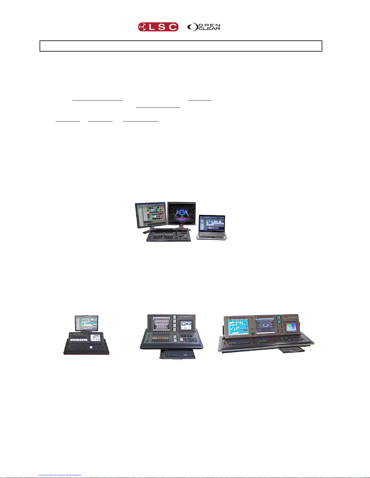
2.1 OVERVIEW
Clarity lighting and media control is available as a Desktop software package for PC or MAC
(with optional USB connected peripherals) or in three console models, LX300, LX600 and
LX900.
There are separate sections in this manual for the Desktop version (with its optional
peripherals) and for each of the Console models.
The software is common to all platforms, however there are small differences that are
particular to each platform due to the different hardware controls of each platform. The
common operating system is described in detail with separate sections for of the various
operations that can be performed. The screen shots used in these sections of the manual are all
from the LX600. There might be slight variations in the screen layout in other modes of
operation.
The Desktop version can be configured to run in desktop mode or to emulate any of the console
platforms. Emulating a console is most useful for pre-programming a show for a console when
the console is not available.
2.2 DESKTOP VERSION
Clarity Desktop
shown with optional VX20 wing and
external monitors.
The desktop version is described in its own section of this manual. A range of USB accessories
are available for desktop operation.
2.3 CONSOLE MODELS
There are three models in the LX range of consoles….
LX300
LX600
LX900
Each console is described in its own section of this manual.
2.4 COMMON FEATURES
The desktop and LX consoles all run the renowned Clarity software with many years of proven
reliability on thousands of shows. Some of the main features of Clarity are:
Full Drag and Drop Patching, with intelligent fixture Cloning.
Rig View with 2D simulation and easy fixture selection.
Page 13

Clarity
Introduction/Models
Operator Manual
Page 5
Seamless fixture substitution, brand to brand, model to model, type to type, etc, from
the world's most comprehensive Fixture Library.
Multiple programmers, each with independent unlimited Undo/Redo.
Media Server Integration with clip thumbnails (supports Arkaos VJ DMX, ArKaos Media
Master, Catalyst, Green Hippo’s Hippotizer, Pandora’s Box, ROBE Digispots).
LED pixel mapping with picture and video playback – maximum size limited only by
available DMX slots.
Full Dynamics Editor and Effects Engine with smooth cross-fading of effects.
Freesets – just like Presets, but independent of fixture type and quantity.
Time Presets and Live Time Busking interface.
Unlimited Groups, Presets, Freesets, Cues and Chases.
Audio playback and time-code synchronization.
Full tracking cue-lists with Macro scripts and Undo/Redo of cue record/delete.
Unique Performance window live interface, a very powerful ad-lib playback matrix grid.
2.5 HELP
The desktop installation includes a copy of this manual that can be found in the LSC folder.
The LX consoles contain a copy of this manual that can be viewed on screen and on-board
video tutorials of common operations. They are contained in the LX Tools utility.
To start LX Tools from the console press Function+Fine+Fine at the same time.
To start LX Tools from the keyboard press Ctrl+Alt+L at the same time.
If you are experiencing problems with Clarity either contact your local LSC agent or post a
message on the LSC forum at http://www.lsclighting.com/forums/
Page 14

Desktop Clarity
Clarity
Operator Manual
Page 6
3 Desktop (PC or MAC) Clarity
3.1 OVERVIEW
Desktop
The desktop version of Clarity consists of a software application and optional control surfaces
and interfaces. In its simplest form, Clarity can be run with just a computer where control is via
a Graphical User Interface (GUI) or Command Line input and output is via ArtNet (DMX over
Ethernet). Hardware can be added in the form of USB to DMX adaptors and USB Playback and
Programming wings that also include DMX outputs.
The desktop version of Clarity is available for both PC and MAC operating systems. Purchased
versions of Clarity desktop include a USB dongle (HASP) that you plug into a USB port of the
same computer that is running Clarity or into the secure compartment in the rear of a VX10 or
VX20 wing. When you start Clarity, it reads the license from the dongle and automatically
enables the channel capability that you have purchased. Multiple dongles can be plugged in at
the same time to increase your available DMX channels.
Your Clarity USB Hasp Dongle is a valuable item. Without it, Clarity will operate in “Demo
Mode” as described below. Therefore you should care for it as you would any other valuable
piece of equipment. LSC recommends that you insure your USB Hasp Dongle against loss, theft
or damage as LSC cannot supply a replacement in these circumstances.
3.1.1 Software
The Clarity software contained on the Clarity CD is also available as a download from the LSC
website, www.lsclighting.com.
Both the CD and downloaded versions are identical although both LSC Lighting Systems (Aust)
Pty. Ltd. and OpenClear Pty. Ltd. have a corporate policy of continuous improvement. To
achieve this goal, we undertake to release software updates for all products on a regular basis.
In light of this policy, the website might contain a later version of Clarity than the version on
your CD or in your console. Please check the web site for the latest version of Clarity software.
3.2 INSTALLING CLARITY ON A PC
When using a PC type of computer, LSC recommends running Clarity on Windows Vista ©,
Windows 7 ©, or Windows 8 © operating systems.
Note: The Clarity software and device drivers must be installed before connecting any QX DMX
nodes or VX wings to your computer.
Install the software by double-clicking on the Clarity installation file supplied on the CD or
downloaded from the LSC website (www.lsclighting.com).
Note: The name of the Clarity installation file will be different depending on which version of
software you are loading but will be of the form Clarity-PC-x.y.z.exe where x.y.z is the version
number of the software.
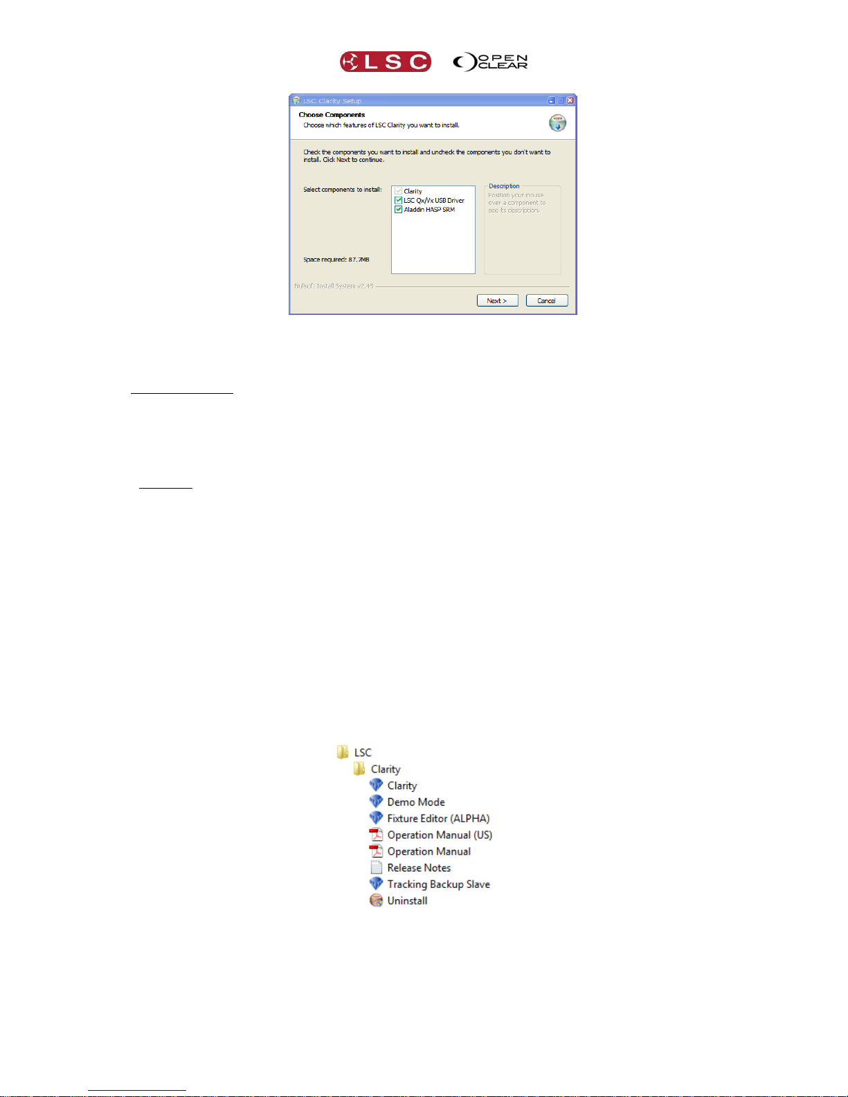
Windows will ask you if you want to allow Clarity to make changes to your computer. Click Yes
and the “LSC Clarity Setup” dialog box appears.
Page 15
Clarity
Desktop Clarity
Operator Manual
Page 7
Components are selected for installation by checking there box. Position your mouse over a
component to see its description.
A new installation of Clarity requires all 3 components to be installed.
Clarity
LSC QX/VX USB Driver
Aladdin HASP SRM
The Aladdin HASP SRM software is for the USB Dongle that contains your Clarity license.
An upgrade to a new version of Clarity only requires 2 components to be installed.
Clarity
LSC QX/VX USB Driver
Continue the installation by clicking Next, then follow the on screen instructions.
The QX/VX drivers are certified 64 bit drivers, however you may be asked to confirm their
installation. Installation of the “Aladdin HASP SRM” software can take several minutes. You can
check the operation as described in “HASP Diagnostics” below.
When the installation is complete, click Close.
If you accept the defaults, Clarity will be installed in C:\Program Files\LSC\Clarity.
You can now plug in a QX DMX node, VX wing or USB license dongle (Hasp). The first time that
you do this, windows automatically installs their device drivers. This takes a few moments and
windows will inform you that “Your device is ready to use”.
To run Clarity, click on Start\All Programs\LSC\Clarity where you will see all of the installed files.
Click on Clarity to run the program.
The above steps are for installation on Windows 7. The process for Windows Vista and Windows
8 will be similar.
Page 16

Desktop Clarity
Clarity
Operator Manual
Page 8
3.3 INSTALLING CLARITY ON A MAC
Previously Clarity-Mac was distributed as an installation package. When you run the package it
displays a wizard that walks you through the installation procedure.
This has now been replaced with a simpler process. Drag the app (Clarity.app) over to the
Applications folder. When you run Clarity for the first time it will automatically install the fixture
library into the Clarity data location (i.e. {home}/Clarity).
3.3.1 HASP Installation for Mac
If you have purchased a Clarity license you will need to install the HASP SRM Runtime.
Double click HASP SRM RTE Installer.pkg
Follow the on screen instructions to install the HASP SRM Runtime.
If you have previously installed the HASP SRM Runtime (possibly from a previous version of
Clarity) then you might see an error message telling you that the software cannot be installed.
This only means that the version already on your computer is the same as the version you tried
to install so it was not required. Click Close.
3.4 HASP DIAGNOSTICS
You can verify that the HASP SRM Runtime is correctly installed by navigating to
http://localhost:1947 to view the “HASP SRM Admin Control Centre”. Make sure you USB
license dongle is plugged into a USB port then click on HASP Keys to verify that your key is
recognized. You might have to refresh the page if you are too quick.
3.5 DEMO MODE
If Clarity is run without a USB dongle it will run in Demo mode. Demo mode has full
functionality but the intensity of all fixtures will black out and all non-fadable channels will
freeze for a short period on a regular basis. It is therefore not suitable for running a show,
Page 17
Clarity
Desktop Clarity
Operator Manual
Page 9
however it is ideal for training and demonstrations or to create off line shows that can be run
on a purchased version of Clarity or on a LX console.
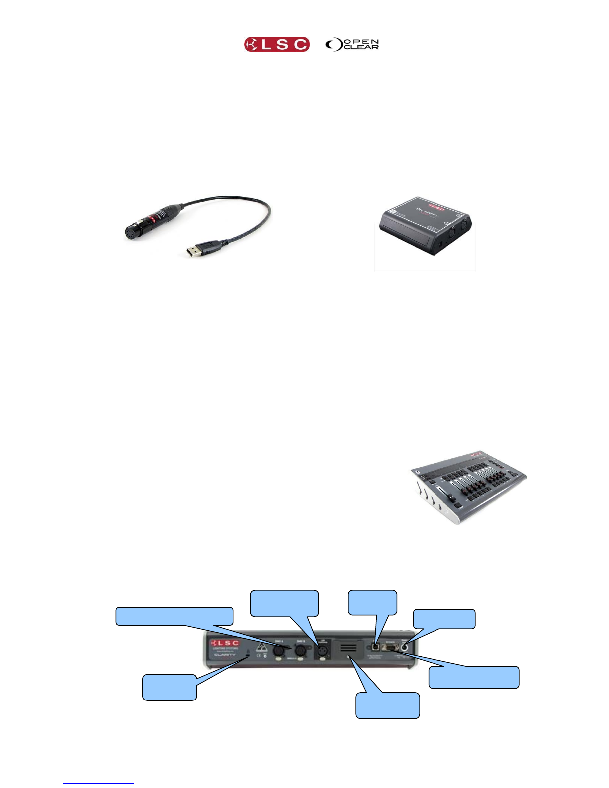
3.6 DESKTOP DMX OUTPUT
DMX512 output is obtained by connecting any of the following devices to the USB port of your
computer. Multiple devices can be connected.
LSC Clarity QX1 interface provides 1 universe of DMX output.
LSC Clarity QX2 interface provides up to 2 universes of DMX output.
LSC Clarity VX10 wing provides up to 2 universes of DMX output.
LSC Clarity VX20 wing provides up to 4 universes of DMX output.
QX1
Provides 1 universe of DMX output
QX2
Provides 2 universes of DMX output
The QX1 and QX2 interfaces are powered directly from the computer’s USB connector. Connect
your DMX controlled equipment to the relevant DMX universe connectors. The DMX outputs are
fully isolated from the USB input.
Note that the DMX output has to be patched in Clarity before it will work. See section 11.12 for
details.
3.7 DESKTOP ARTNET OUTPUT
ArtNet is a protocol that is transmitted over Ethernet LAN (Local Area Network) or WAN (Wide
Area Network) and supports up to 255 DMX Universes on a single cable. To use ArtNet it must
be connected to the internal universes within Clarity in the Patch window. See section 11.13 for
details.
3.8 VX10 PLAYBACK WING
Control of Playback on a computer can be augmented by adding an
LSC Clarity VX10 playback wing. This provides 10 fader Playbacks
with LCD displays and multiple page selection, a Grand Master and
DBO (Dead Black Out), two DMX512 universe outputs, remote
trigger inputs and a secure compartment for installing your license
dongle and a front panel USB port.
Connect the VX10 wing to a USB port of your computer using the cable provided. The VX10 is
powered directly from the computer’s USB connector. A separate power supply is required
when your computer’s USB connector cannot supply sufficient power for the VX10.
VX10 Rear Panel
The rear panel is described in detail below.
Power Input
LED Desk
Lamp Socket
2 DMX Universe Outputs
USB dongle
compartment
Remote Trigger
Inputs
USB to
Computer
Kensington
Lock slot
Page 18

Desktop Clarity
Clarity
Operator Manual
Page 10
3.9 VX20 PROGRAMMING & PLAYBACK WING
Programming controls on a computer can be augmented by
adding an LSC Clarity VX20 wing. This has all of the features of
the VX10 but adds 10 button Playbacks with LCD displays and
multiple page selection, Programmer controls (including
trackball), MIDI in and out and includes four DMX512 universe
outputs.
Connect the VX20 wing to a USB port of your computer using the cable provided. The VX20 is
designed to operate off USB power, however for some computers and when using a LED
gooseneck light, there may be insufficient USB power to operate the VX20. To cater for this,
the VX20 is fitted with an internal universal mains power supply. We recommend connecting
the VX20 using the supplied IEC cable to a source of 85 to 264 Volts AC mains power wherever
possible. The backlight for the LCD screen only works when external power is connected.
VX20 Rear Panel
3.9.1 USB Indicator
The LED beside the USB connector shows the status:
Flashing RED = No USB connected. (The DBO button also flashes)
Steady RED = USB connected but Clarity not running on computer.
Green = USB data is OK.
3.9.2 DMX Indicators
The LED beside each DMX connector shows the status:
Green = DMX data is OK.
3.9.3 Desklamp
The Desklamp socket provides 12volts power for a LED. Pins 1 and 2 are ground and pin 3 is +12
Volts. The brightness control is accessed by holding down Function and Select together.
3.9.4 Kensington Lock Slot
The Kensington Lock slot allows you to secure your VX10 or VX20 wing using a commercially
available tethering device.
3.9.5 USB Slot
The top panel of the VX10 and VX20 wings has a standard USB connector allowing you to connect
other USB devices such as memory devices to store your shows.
Multiple VX10 and VX20 wings can be connected to your computer.
Note: The QX and VX products are designed to be powered from the USB port on our computer.
However due to the design of some computers or your particular configuration, there may not be
enough power to operate the VX products. If you experience problems in the installation process,
first try a different USB port on your computer or try powering the VX10 with an external power
supply or if you have a VX20, plug it into the mains supply. If you still experience problems,
check the LSC website or contact your local dealer.
Note that the DMX output has to be patched in Clarity before it will work. See section 11.12 for
details.
4 DMX Universe Outputs
LED Desk
Lamp Socket
Mains Input
USB to
Computer
Remote Trigger
Inputs
MIDI In
MIDI Out
USB dongle
compartment
Kensington
Lock slot
USB Indicator
DMX Indicator
Page 19
Clarity
Desktop Clarity
Operator Manual
Page 11
3.10 STARTING CLARITY
If you are running a purchased copy of Clarity, please ensure that your USB license dongle is
plugged into a USB port on the PC or in the secure rear port your VX10 or VX20 wing before
you start Clarity.
To start Clarity, double click on the Clarity icon on your desktop or browse to the LSC menu
from your Start button.
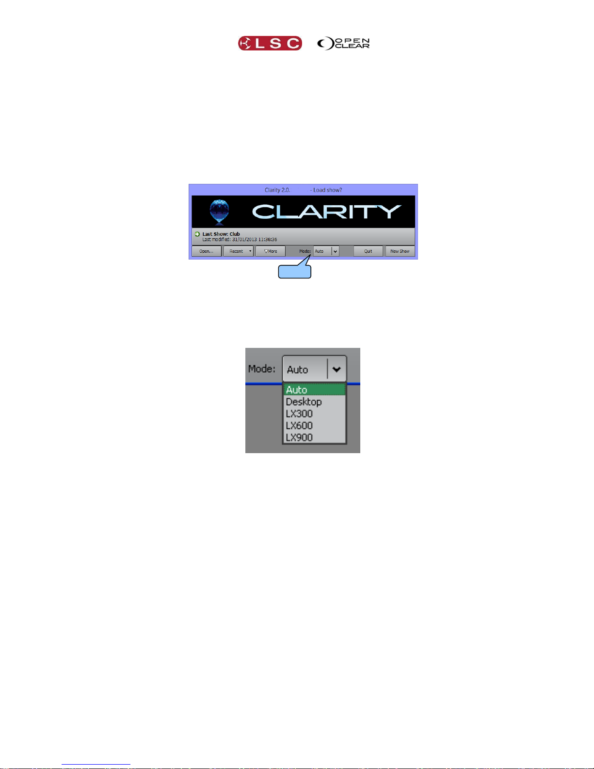
3.11 LOADING A SHOW
When you start Clarity, it prompts you to load a show.
The Mode: function allows you to run Clarity as a normal desktop version or to emulate a
console version of Clarity (LX300, LX600 or LX900) on your computer. If “Mode” is left as Auto,
then the mode is determined from the show file that is loaded. For example, if you load a show
saved on a LX600 then Clarity will start up in LX600 emulation mode. Clicking the dropdown
box allows you to make a selection.
Selecting a console mode is particularly useful when you are creating or editing a show on the
desktop version that will be loaded onto a console version of Clarity. Once you have made your
selection………
Clicking Last Show loads the last show to be saved.
Clicking Open shows a standard file navigator allowing you to select any show.
Clicking Recent opens a drop down box containing your most recent shows.
Clicking New Show starts a new show.
3.11.1 Show Tab
When Clarity is running you can always start a new show, change to an existing show, save or
rename a show from the Show tab on the top toolbar. Selecting “Change show…” allows you to
also change the “Mode” as described above and below.
Mode:
Page 20

Desktop Clarity
Clarity
Operator Manual
Page 12
3.12 MODES OF OPERATION
Clarity's top toolbar is available in all modes of operation and has tabs allowing you to switch
between the main windows of: Patch, Rig, Programmer, Palettes, Control Booth,
Performance, Levels and Intensity Levels.
Desktop Mode
When Clarity is started in a LX console emulation mode (described above), the main window is
contained within a special ‘wrapper’ window which can be scrolled to navigate the main
window. This allows the main window to remain at the original size it would be on the console
to preserve graphical layouts and positions.
LX300 emulation Mode
LX600 emulation Mode
LX900 emulation Mode
The wrapper window’s toolbar provides several options:
Fullscreen. The wrapper is set to full screen mode and the wrapper’s toolbar is hidden.
Resizable. The main window’s size will follow the size of the wrapper window and the
scrollbars are hidden, unless the wrapper window is smaller than the main window’s
minimum size.
Hide toolbar. This option replaces the window wrapper’s toolbar with a small yellow
disc on the top right of the wrapper window. Clicking on this presents the toolbar
options as a drop-down menu.
Page 21

Clarity
Desktop Clarity
Operator Manual
Page 13
Split/Join (LX900 mode only). The LX900 has two internal monitors. This splits the
wrapper into two separate wrapper windows. If this is running on a system with two or
more monitors then the other wrapper window will be presented on the other monitor
and will appear full screen if the original wrapper was full screen.
Left/Right (LX900 mode only). This switches the view between the LX900’s left or right
internal monitors (unless the wrapper has been split). The left monitor of the LX900
displays the “Levels”, Intensity Levels” and “Performance” windows.
Playback display mode (LX600 or LX900 modes). The LX600 and LX900 have
playback displays positioned at the bottom of the main screen(s) and this controls how
they are presented in the wrapper:
o Auto. If the main window size is normal (1280x1024) then the playback display
is positioned at the bottom as usual. If the Resizable option is enabled then the
playback display is only displayed if the main window size is 1280x1024. For
example, if running on a 1280x1024 host system in full screen mode.
o Always Hidden Playback displays are never shown.
o Always Visible Playback displays are always shown at the bottom of the main
window even if the main window size is not 1280x1024. Note that if the main
window width is less than 1280 then the playback display will be truncated.
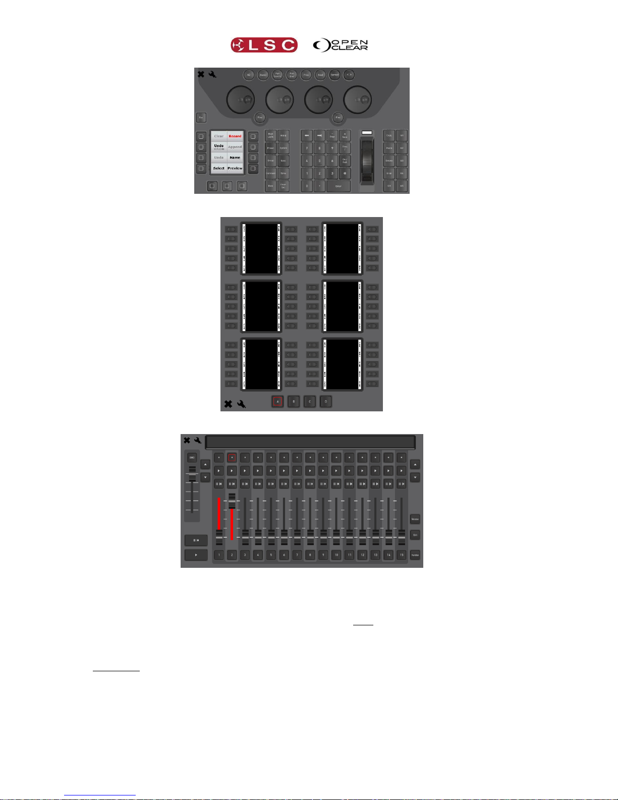
3.12.1 Console Window
When running in an emulation mode, a top-level Console tab is provided to show the console’s
internal encoder wheel touch screen and includes tabs for displaying the virtual control surfaces
of the relevant LX console.
For example, the LX600 Console tab allows you to select the LX Programmer, LX Action
Buttons and LX600 Playbacks controls:
Click here for
display options
LX Controls
Page 22
Desktop Clarity
Clarity
Operator Manual
Page 14
LX Programmer
LX Action Buttons
LX600 Playbacks
The buttons and faders all work as if they were on the actual console.
If you need to press two buttons at the same time, pressing and holding a button for 1 second
will latch that button down. For example, if you wanted to hold the Function modifier or one of
the wheel modifier buttons you latch it by holding it for one second. Press it again to un-latch
it.
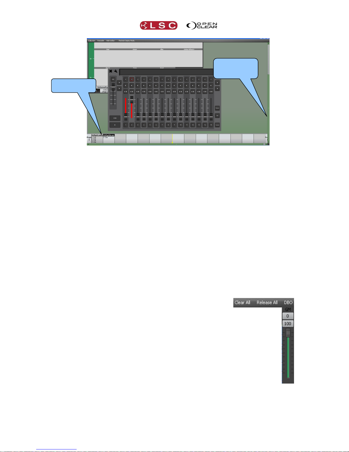
The playbacks on the LX600 and LX900 do not have dedicated contents displays as in the
LX300 but show their contents on the touch screen located above them on the console. These
displays are emulated at the bottom of the screen on your computer. Depending upon the
screen resolution of your computer you might have to scroll to the bottom to see the playback
displays.
Page 23
Clarity
Desktop Clarity
Operator Manual
Page 15
LX600 Playbacks with main screen scrolled down to see the playback displays.
The playback controls work in exactly the same manner as in the actual consoles. See the
playback sections of the consoles for details.
When hovering over an emulated LCD screen, a zoomed version of the LCD is presented to aid
readability. This is also configurable via the tool menu. The emulation views also snap to screen
boundaries and to each other to aid layout.
3.13 BASIC DESKTOP OPERATION
The tabbed windows of the main menu bar follow the same order as the basic steps used in
control lighting fixtures.
1. Patch allows you to select your fixtures from a fully integrated fixture library of over
2000 fixture personalities supplied by Carallon, an independent supplier of fixture
libraries. You patch a fixture to its DMX slot by drag and drop.
2. Rig, Programmer and Palettes allow you to select fixtures and control their attributes
to create (record and edit) looks, effects, cue lists and palettes.
3. Control Booth and Performance provide extensive methods of playback.
4. Levels shows you what is happening on the output.
All of these operations are described in detail in their relevant sections of this manual.
The right end of the top toolbar has buttons for Clear All, Release All and DBO.
Clear All clears all fixtures from all Programmers.
Release All releases all fixtures from all Playbacks.
See the Programmer and Control Booth sections for more details on Clearing
and Releasing.
DBO (Dead Black Out) instantaneously blacks out all fixtures and dimmers.
This is a momentary action. When the button is released, all output is
instantly restored.
GM (Grand Master). When you hover the mouse over the DBO button, the
Grand Master (GM) appears. You can click on 0 (Black Out) or 100 (Full
level) or drag the virtual fader to set an overall intensity level. The DBO
button flashes red if the Grand Master is set to any level below 100%. It
stays red when the Grand Master is set to 0%.
Display scrolled
to see Playback
contents
Playback
contents
Page 24

Desktop Clarity
Clarity
Operator Manual
Page 16
3.14 PATCHING
Clicking on the Patch tab reveals the patch window.
To patch a fixture:
In the Library, click on the fixture manufacturers name to show all of their models then
select your model of fixture. Dimmers are located in the “Generic” listing.
Drag the fixture name and drop it into the desired DMX slot in the Patch Field or double
click the fixture name to patch it to the next available slot.
Enter the quantity of fixtures in the pop up “Add Devices” dialog then click Patch.
Continue to select fixtures and patch them as above.
In the “Connections” Pane, click the down arrow beside the Universe that you have
patched your fixtures to and then select the output DMX connector to use.
Library
Patch Field
Connections
Information on
selected fixture
Page 25

Clarity
Desktop Clarity
Operator Manual
Page 17
3.15 PROGRAMMING
Clicking on the Programmer tab reveals the programmer window.
All patched fixtures are available in the Selection sidebar, organized in tabs of patched fixture
types and groups.
Select the tab for the fixtures to control then click on the fixtures to select them.
Click and drag to quickly select multiple fixtures.
Clicking on a selected fixture de-selects it.
When a fixture(s) is selected, its attribute controls appear.
Fixtures can also be selected in the Rig view. See section 12 for details.
3.15.1 Attribute Controls
Clarity uses Attribute Controls in many of its windows to control the values of fixture attributes,
dynamic effects and timing controls. Specific Attribute Controls automatically appear when
required for the fixtures or objects that you select.
Attribute Controls are adjusted by clicking and dragging with a mouse anywhere within each
attributes window.
A single Attribute Control for controlling one dimmer looks like this:
To adjust the intensity of the dimmer, click and drag anywhere in the bar below the attribute
name “Intensity”.
If seven dimmers are selected the Attribute Control looks like this:
To adjust the intensity of all 7 dimmers, click and drag anywhere inside the bar. All these
dimmers are set to 50%.
Fixture type and
Group Tabs
Click on Fixtures
to select them
Attribute
Controls
Universal
Controller
Selection
Sidebar
Page 26
Desktop Clarity
Clarity
Operator Manual
Page 18
When you select different fixtures that have multiple attributes, Attribute Controls
automatically appear for each type of fixture and each attribute of each fixture type.
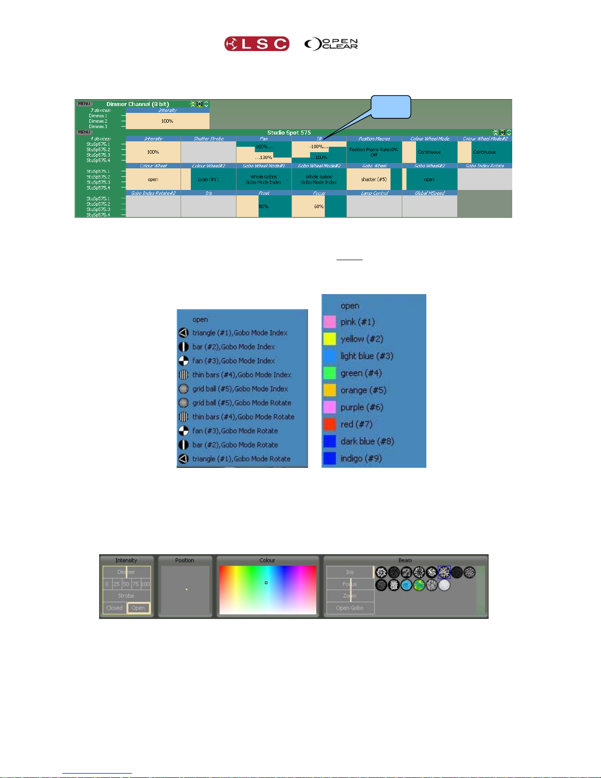
3.15.2 Attribute Quick Menus
To access the “Attribute Quick Menus, either click on the name of an Attribute Control or right
click in the Attribute Control area. Each individual Attribute Control has its own specific quick
menu, offering rapid access to common settings relevant to that attribute.
For example:
Gobo Colour
Typical Attribute Quick Menus
3.15.3 Universal Controller
The Universal controller at the bottom of the Programmer window can also be used to control
the attributes of all selected fixtures. These controls work with any type of fixture that has been
selected and are especially useful to simultaneously control selections of mixed fixture types.
Clicking and dragging in these controls uses low mouse gearing for accurate control, but can be
made even finer by holding down [Shift] whilst dragging.
3.15.4 Creating a Lighting Look
Select the fixture(s) to be controlled.
Use the Attribute Controls or the Universal Controller to get the desired look.
To record the look as the first cue in a cue-list click Record.
In the Record dialog that opens accept the defaults and click Record.
Select fixtures and adjust attributes to set the next look.
Attribute
Name
Page 27

Clarity
Desktop Clarity
Operator Manual
Page 19
To record this look as the next cue in the Cue-list click Append Last.
Repeat until all cues in the cue-list have been recorded.
Click Clear to clear all attributes from the Programmer.
3.16 PLAYBACK
Desktop Clarity provides several means of playing back the cues that you have recorded.
3.16.1 Control Booth
Clicking on the Control Booth tab reveals the Control booth window.
Clicking on a Cue-list (that you have recorded) allows it to be controlled by the buttons
in the “Control” pane.
Dragging a Cue-list to the Playbacks pane creates a new Playback with buttons and a
fader to control the Cue-list. Multiple pages of Playbacks are available. The function
buttons of your computer keyboard (F1 through F7) act as “Go” buttons for playbacks 1
to 7 respectively.
3.16.2 Adding a Virtual VX Wing
Cue-lists are assigned to the playbacks on VX wings in the Control Booth window by drag and
drop onto a virtual copy of the selected wing on the Clarity screen. When a wing is plugged into
the computer running Clarity, the real and virtual wings both operate simultaneously. Move a
fader on the real wing and the same fader on the virtual wing also moves. Click a button on the
virtual wing and both it and the real wing button light.
To add a virtual wing you must be running in “Desktop Mode”. In the
Control Booth window click Hardware, Manage and in the Hardware
dialog box select add virtual wing....
From the Add new device box drop down list select your model of
playback wing or DMX node and click OK then Close.
3.16.3 Selecting a Virtual VX Wing
To select a Virtual Wing, in the Control Booth window click Hardware,
then click on the name of the Wing that you added above (Clarity VX10
or Clarity VX20). The selected wing appears on the screen. The virtual
wing is fully functional except that the Grand Master is not activated until a
hardware USB wing is connected.
Cue-lists
Controls for
Selected Cue-list
Playbacks Pane.
Drag and drop cue-lists to
create Playbacks
Hardware
Page 28

Desktop Clarity
Clarity
Operator Manual
Page 20
VX20 Virtual Wing Display
3.17 ADDING A CUE-LIST TO A VX WING
To add a cue-list to a playback on a wing, in the Control Booth window, drag the cue-list
from the cue-list column onto the LCD window of the virtual wing playback. If the actual
wing is connected, the cue-list also appears in the same playback as on the virtual wing.
Cue-lists already on a wing playback can be moved to a different playback by dragging
them on the virtual wing.
To copy a cue-list to another playback, hold [Ctrl] (PC) or [Cmd] (Mac) whilst dragging
on the virtual wing.
3.18 WING PLAYBACK PAGES
The playbacks on the Clarity VX10 and VX20 wings can have up to 99 pages of cue-lists.
On the VX10 wing, the Page Buttons select the current page for all 10 playbacks.
Playbacks and Page Buttons on a VX10 Wing
On the VX20 wing, playbacks are divided into 2 separate banks. Playbacks 1 to 5 and 11 to 15
are in the left bank and playbacks 6 to 10 and 16 to 20 are in the right bank and each bank has
separate Page Buttons.
Playbacks and Page Buttons on a VX20 Wing
Virtual VX20 Wing
Left Bank
Page buttons
and display
Left Bank
Playbacks
Right Bank
Playbacks
Right Bank
Page buttons
and display
Page buttons
and display
Playbacks
Page 29

Clarity
Desktop Clarity
Operator Manual
Page 21
When you start a new show, only page one exists. When a cue-list is dropped onto any
playback on a page of a virtual wing, the next higher page is automatically created.
You can manually create any page number (up to 99) by directly selecting that number as
described below. This also automatically creates all of the in between pages up to the selected
page number.
The page number display beside the page buttons shows a ▲ or ▼ symbol when a higher or
lower page exists.
Pressing Page ▲ or Page ▼ selects the next higher or lower page number.
To directly select any page number, hold either Page ▲ or Page ▼ and use the
numbered [flash] buttons below the faders to enter the page number.
For example, to go to page 21, hold either Page ▲ or Page ▼ and tap 2, 1.
Use the 10 button as a 0.
Holding Function and pressing Page ▲ or Page ▼ increments or decrements the page
number by 10.
3.18.1 Locking a Playback
A playback on a VX wing can be locked so it is unaffected by page changes. On the virtual
wing, right click on the playback and select Lock this playback. The letter L is displayed.
3.18.2 Page Bookmarks
Page bookmarks allow instant recall of pages. See section 8.7.10 for details.
3.18.3 Managing VX Pages
Pages can be re-ordered and named. See section 8.7.9 for details.
3.19 WING PLAYBACKS
VX20 Playback masters
The area of the LCD screen adjacent to each playback shows the name of any cue-list that is on
the playback and also the names of the current cue and the next two cues in the cue-list.
GM (Grand master): controls the overall intensity of all fixtures on the output. If more
than one VX wing is connected, the Grand Masters work on a Lowest Takes Precedence
basis.
DBO (Dead Black Out): Whilst held down, it blacks out all intensity of all fixtures on the
output.
1-10 Intensity Flash
Grand Master
DBO
Left Bank Page
Right Bank Page
Function
Select
Release
Edit
Record
Pause/Go Back
Master Go
11-20 Play
11-20 Pause
1-10 Go
1-10 Pause
1-10 Intensity Faders
LCD screen
Page 30

Desktop Clarity
Clarity
Operator Manual
Page 22
Intensity fader: that controls the overall intensity of all fixtures on the output of its
playback (Playbacks 1 to 10 only).
Flash button: Instantly flashes the intensity of all fixtures on the playback to full level
(Playbacks 1 to 10 only). Also see “Solo” and “Solo Safe” in section 24.2.1
(Go): Plays the next cue in the cue-list or restarts a paused fade. Pressing will
start the fade to the next cue even if the current fade has not finished.
Press Function+ to snap to the next cue.
o The indicator in the button lights during the transition to the next cue.
o The indicator in the button slowly flashes if any of the attributes in the cue have
been overridden.
If the playback contains a chase, pressing will start the chase. If you continue tapping
(to the beat of the music) it will automatically adjust the chase speed to the beat.
II I Pauses any fades in progress. If no fades are in progress, if fades back to the
previous step.
Press Function+ II I to snap to the previous cue.
o The indicator in the button lights when the fade to the next cue has completed.
Select: Selecting a playback allows it to be controlled by the Master and Master II I
buttons and also selects the playbacks cue-list in the Control Booth window allowing you
to see and or change the playback settings of the cue-list.
o To select a playback tap Select then tap any button of the desired playback.
o The cue-list name of the “currently selected cue” is displayed in reverse video (black
text on white background).
(Master Go): Plays the next cue or restarts a paused fade of the selected playback.
See Select above.
II I (Master Pause /Go Back): Pauses the fade of the selected playback. If no fade is
in progress, if fades back to the previous step. See Select above.
Release: To release a playback, tap Release. All buttons of all playbacks flash. Tap
any button of the playback to be released.
To clear (remove) a cue-list from a playback, right click on the name of the cue-list on
the virtual playback then click Clear.
Edit: To edit a cue on a playback, tap Edit. All buttons of all playbacks flash. Tap any
button of the playback to be edited.
Record: opens the Record Cue dialog box.
To append a cue to the last recorded cue-list, press Record twice.
To record the cue on a playback on a VX wing, press Record then press the flash
button of that playback.
Page: the Page buttons are described earlier in this section.
3.20 WING GROUP MASTERS
You can configure any of the VX wing fader playbacks (or Control Booth playbacks) as fixture
“Group Masters”. When a playback is converted into a Group Master, it no longer controls its
previous cue-list (if any) but instead acts as a submaster over the intensity of the selected
group as determined by your choice of either “Additive, Scale+, Inhibiting or Limiting”
mastering as described below.
To create a Group Master on a wing, in the Control Booth window, Right click on the LCD
window of the virtual wing playback and select Set as Group Master...
See above for details on how to display the virtual wing.
Page 31

Clarity
Desktop Clarity
Operator Manual
Page 23
On the “Create Group Master Dialog” select the required fixture Group to master then choose
the Master Type to use:
Additive. The fader level is added to the current intensity level of all fixtures in the group.
For example, if the fader is at 50% each fixture would get 50% added onto its current level.
So fixtures at 25, 50 and 75% would end up at 75, 100 and 100 percent.
Scale +. This scales each intensity level between its current level and full.
For example, if the fader is at 50%, a fixture at 25 would be set half way (50%) between
25 and full which is 62.5%. A fixture at 50 would be set half way (50%) between 50 and full
which is 75% and a fixture at 75 would be half way between 75 and full which is 87.5%.
Inhibitive. This is the default, and operates in the same way as a fader assigned to a cue-
list.
For example, if the fader is at 50%, fixtures at 25, 50 and 75% would be at 12.5, 25 and
37.5%.
Limiting. The intensity level of each fixture is capped to the fader level.
For example, if the fader is at 50%, fixtures at 25, 50 and 75% would be at 25, 50 and
50%.
If the actual wing is connected, the LCD shows the status of the fader as a Group Master.
A group master on a wing will be deactivated when it is not on the currently selected page. You
can change this by un-ticking Deactivate group masters while paged out in the “User
Preferences”.
When a playback on a VX wing has been programmed as a Group master, it’s (Go) and II I
buttons now act as Group select and Group deselect buttons. Therefore, pressing the
button of that Group Master on the VX wing will select all of the fixtures in that group in the
Programmer.
3.21 EXTENDED WING CONTROLS
Unused playbacks on a VX10 or VX20 wing can be used as extra control buttons and faders for
another playback on that wing that contains a cue-list. The playbacks on a wing are arranged in
groups of 5:
A VX 10 wing has 2 groups of playbacks, 1 to 5 and 6 to 10.
A VX 20 wing has 4 groups of playbacks, 1 to 5, 6 to 10, 11 to 15 and 16 to 20.
Page 32

Desktop Clarity
Clarity
Operator Manual
Page 24
If a cue-list is loaded on a playback and there are un-used (clear) playbacks to the right of the
loaded playback in the same group of 5, then the unused playbacks can now be linked to the
loaded playback to provide greater live control. The previously unused playback’s buttons and
faders can now be used for live control of Chase Rate, Playback Rate, FX Rate and FX
Amplitude.
To create extended controls on a wing, in the Control Booth window, Right click on the loaded
playback’s LCD window of the virtual wing playback and choose either single, 2, 3, 4 or 5
columns. The number of columns that are available depends upon the number of clear
playbacks to the right and in the same group of five playbacks.
The 4 playbacks to the right are clear so up
to 5 columns can be selected.
The 2 playbacks to the right are clear so up
to 3 columns can be selected.
Each column represents a playback on the wing.
The first (single) column is the playback loaded with the cue-list.
If you choose 2 columns then the playback to its right controls that cue-lists
Chase Rate.
If you choose 3 columns then the next playback to the right controls that cue-lists
Playback Rate.
If you choose 4 columns then the next playback to the right controls that cue-lists
FX (Effects)Rate.
If you choose 5 columns then the next playback to the right controls that cue-lists
FX (Effects) Amplitude.
The buttons and fader on each of these playbacks (columns), now perform the following
functions:
Pressing Play or Pause steps the values up or down respectively. If you hold the button
it will auto-repeat after a delay.
Holding the Flash button when pressing Play or Pause makes them step in larger
increments.
Pressing both Play and Pause together resets to the default value.
Holding the Flash button allows you to use the fader to make fine adjustments to the
value. If you reach a fader end-stop but you need to more range, you can release the
flash button and move the fader to the opposite end, then hold flash and move fader to
continue adjusting the value. This is known as “scooting” the fader. The user preference
“Invert flash button operation on rate faders” changes this operation so that you just
move the fader without holding flash to adjust the value, then (if you reach the fader
end stop) hold flash to reposition the fader. So the fader is always connected giving you
Cue-list
being
controlled
Controls
Chase
Rate
Controls
Playback
Rate
Controls
Effects
Rate
Controls
Effects
Amplitude
Page 33

Clarity
Desktop Clarity
Operator Manual
Page 25
instant control but you can hold the Flash button down to 'scoot' the fader. See section
34.1 for User Preferences.
3.22 PROGRAMMING WITH THE VX20 WING
The VX20's programmer section assists programming by providing hard controls for the main
programming functions.
3.22.1 Trackball
The trackball is multi-purpose and can be used for Programming and as a computer mouse.
Pressing either Intens (Intensity), Position, Colour or Beam turns the track ball blue
and causes the trackball to vary the Intensity, Position, Colour or Beam values of the
selected fixtures in the current programming session.
Pressing the (mouse) button turns the trackball green and causes it to act as a mouse
for the computer running Clarity. When (mouse) is selected the Ortho and Fine
buttons act as the Left and Right mouse buttons respectively.
The Intensity, Position, Colour, Beam and Mouse buttons are all interlocked so that selecting
any one button deselects the previous button.
3.22.2 Programmer Buttons
The programmer buttons have the following functions:
Next, All, Prev, None, HiLit (Highlight), Blind, Clear All, Release All: Perform
identical functions to the same buttons on the Programmer window's toolbar in the GUI
(Graphical User Interface). See section 21 for details.
o The Clr All button lights when any attributes have been grabbed in either
programmer.
o The Rel All button lights when any playbacks are active on the output.
Hint: Inadvertently pressing Rel All will blackout all Playback. To prevent this you
can set a “User Preference” to require both Function and Rel All to be pressed
together to release all playbacks.
Ortho: (Orthogonal) Holding Ortho whilst moving the trackball restricts the trackball
output to only horizontal or vertical movements, whichever occurs first. When in mouse
mode (above) it acts as a Left mouse button.
Fan: When multiple fixtures are selected, holding Fan whilst moving the trackball will
fan the values of those attributes. (The same as holding [Ctrl] (PC) or [Cmd] (Mac)
when dragging with the mouse in the GUI).
Fine: Holding Fine whilst moving the trackball gives finer control. (The same as
holding Shift when dragging with the mouse in the GUI).
When in mouse mode (above) it acts as a Right mouse button.
Clear All
Beam
Release All
Fine /
Right Mouse Button
HiLite
Intensity
Position
Trackball
Fan
Ortho /
Left Mouse Button
None
All
Prev
Next
Mouse Mode
Colour
Blind
Page 34

Desktop Clarity
Clarity
Operator Manual
Page 26
Record: opens the Record Cue dialog box and all playback buttons on VX wings flash.
To record the programmer contents to a VX20 playback, press any (flashing) playback
button. If the playback is empty a new cue-list will be created. If the playback already
contains a cue-list, the new cue will be appended to the end of that cue-list.
To append a cue to the last recorded cue-list, press Record a second time.
3.22.3 VX20 Soft Menus
The top row of playback buttons can be toggled to become additional programming buttons
acting as shortcuts for some common operations. To switch the buttons between normal
playback operation and soft functions, right-click on the VX20’s virtual wing display and select
Toggle soft menus.
There is only a single row of functions, and both buttons above each label will trigger the same
function as shown on the LCD display.
Soft Menu Functions
Left Bank Soft Menus
Undo Prog
Undo Ctrl
Auto
Update
Clear Prog
Save All
Undoes the last
operation in the
current Programmer.
Undoes the last
operation in the
Control Booth.
See
section
21.8.8
Removes all
attributes from the
current Programmer.
Saves all
currently open
edit sessions.
Right Bank Soft Menus
Grab Active
Rem Dim
Prog 1
Prog 2
Esc
Grabs all attributes
that are active on
the output into the
current
Programmer.
Unselected fixtures
currently grabbed in
the programmer have
their intensity in the
Programmer set to
zero.
Selects
Programmer 1
as the current
session.
Selects
Programmer 2
as the current
session.
Closes
any
open
dialog
boxes
Page 35

Clarity
Desktop Clarity
Operator Manual
Page 27
3.23 EXTERNAL CONTROL INPUTS
The “external Inputs” 9-pin D-SUB connector on the back of the VX10 and VX20 wing can be
used to connect up to 6 external push buttons that act the same way as the “Go” buttons on
the playbacks. The connector is wired to accept 6 inputs in the form of contact closures.
VX10
VX20
The external inputs control GO buttons 5
to 10
The external inputs control GO buttons 15 to 20
The pin assignments on the 9 pin D-SUB connector are:
Pin
VX 10 Button
VX20 Button
1
Go 5
Go 15
2
Go 6
Go 16
3
Go 7
Go 17
4
Go 8
Go 18
5
Go 9
Go 19
6
Go 10
Go 20
9
Common
Common
To remotely operate a Go button, provide a contact closure (short circuit) from its control pin to
the common pin.
3.24 VX20 MIDI
A MIDI signal connected to a VX20 wing can be used to remotely control the playback of the
“selected” playback that wing. A playback is selected on a wing by pressing Select then any of
the flashing buttons of that playback. The cue-list name of the currently selected playback is
displayed in black text on a white background.
MIDI “Note ON” messages can be assigned to trigger the Go, Pause/Back, Release and
Jump functions of the selected playback on a VX20 wing.
MIDI “Control Change” messages can be used to pre-select a cue in the cue-list of the
selected playback that will be triggered by the next “Note on” message to be received
that is assigned to the “Jump” function.
See section 30 for details on the VX20’s MIDI functions.
Pin 9
Pin 1
Circuit to operate
Go button 5 on a VX10
or Go button 15 on a VX20
Page 36

Desktop Clarity
Clarity
Operator Manual
Page 28
3.25 DESKLAMP INTENSITY
The brightness of the LED desk light on the VX wing control can be controlled by holding down
[Function] and [Select] together.
3.26 FREE MODE
Early versions of Clarity will run in free mode. Clarity will only run in free mode if it was
downloaded as version 1.3 or earlier and registered for free mode prior to April 8, 2011. To
continue running the free version it must be upgraded to version 1.3.2 and cannot be upgraded
further. The following restrictions are applied to the free mode of Clarity:
Limited to a single universe output of 32 fixtures and 128 channels.
The VX10 and VX20 wings have the front panel controls (LCDs, faders and buttons) and
the remote trigger inputs disabled. However the DMX outputs on the rear and the USB
port on the top still work.
MIDI functionality is disabled.
Media Servers functionality is disabled.
Matrix functionality is disabled.
RDM functionality is disabled.
Tracking Backup is disabled.
The template request service is not provided to users of the free version, however Clarity
does have a built-in fixture editor which can be used instead.
Technical support for the free version is via the user forums only.
Page 37

Clarity
LX Consoles
Operator Manual V2.0
Page 29
4 LX Consoles
4.1 OVERVIEW
There are three models in the Clarity LX range of consoles….
LX300
LX600
LX900
Sections 5, 6 and 7 of this manual describe the rear panel connections and the front panel
control surfaces of each model respectively.
There are several areas on the consoles that are common to all models. These common
controls are described in section 8.
The software is common to all platforms however there are small differences that are particular
to each platform due to the different hardware controls of each platform. The common
operating system is described in detail with separate sections for of the various operations that
can be performed. The screen shots used in these sections of the manual are all from the
LX600. There might be slight variations in the screen layout in other modes of operation.
The Desktop version of Clarity can be configured to run in desktop mode or to emulate any of
the console platforms. Emulating a console is most useful for pre-programming a show when
the console is not available.
Page 38

LX300
Clarity
Operator Manual
Page 30
5 LX300 Console
5.1 OVERVIEW
LX300 with External Monitor
The LX300 has the following features:
One 10.4 inch “encoder wheel touch screen”.
15 Fader Playbacks. Each playback has a fader with RGB mode indicator plus Select, Go
and Pause/Back buttons. 99 pages of memory.
15 Button only playbacks. Each playback has Select, Go and Pause/Back buttons.
99 pages of playback memory split into left and right pages.
Individual full color screens for each playback.
Four DMX512/A output connectors (XLR5).
DMX capacity up to 2,048 DMX slots.
Accepts external USB alphanumeric keyboard.
One DVI monitor output.
MIDI In, Out, Thru.
Audio In & Out via 3.5mm sockets.
Dual Gb Ethernet ports.
IEC Power Input.
160GB Shock protected disc storage system.
5.2 LX300 REAR PANEL
Mains Input
LED Desk lamp
socket
LED Desk lamp
socket
Reset Button
External
Inputs
MIDI In, Thru
& Out
4 DMX Outputs,
A, B, C & D
Audio IN
Audio OUT
4 USB sockets
Ethernet 1
Ethernet 2
DVI Video Out
DMX Active LED
Mains Switch
Page 39

Clarity
LX300
Operator Manual
Page 31
5.2.1 Power Input and Mains Switch
An IEC mains input socket and mains switch connects to the LX300 universal power supply that
operates on input voltages between 100 volts and 240 volts, 50-60 Hertz AC. The maximum
power consumption is 450 watts.
5.2.2 DMX Outputs
Four DMX universes (A, B, C and D) are available. To use these outputs they must be
connected in the Patch window to the internal universes within Clarity. The LED below each
DMX connector lights when it is connected. See section 11 for details.
5.2.3 Ethernet
Two identical Ethernet connectors provide DMX output via ArtNet. ArtNet is a protocol that is
transmitted over Ethernet LAN (Local Area Network) or WAN (Wide Area Network) and supports
up to 255 DMX Universes on a single cable. If an internal DMX universe is connected to ARTNet
(in the Patch window) then it appears on both Ethernet connectors. See section 11.13 for
details.
Hint: When using ArtNet, you can connect both Ethernets and use them as main and back up
into two independent (dual redundant) networks. The two networks can be connected into an
LSC Nexus (ArtNet to DMX converter) which can accept both networks and will automatically
change over in the event of a loss of a network.
The Ethernet connectors can also be used to connect the LX300 to a network or wireless access
point for remote control. See section 31 for details.
5.2.4 DVI Video Out
An external monitor with a minimum resolution of 1280x1024 is required to operate the LX300.
The monitor must be connected before switching on the console. Connect the monitor or touch
screen to the Video Out connector using a DVI cable. A HDMI monitor can be connected via a
DVI to HDMI converter plug. (Not supplied).
Note: The LX300 will not start correctly if an external monitor is not plugged in.
See section 35 (LX Tools) for details on how to setup the external monitor. Only compatible
external touch screens can be used. Contact LSC or your local LSC dealer for compatible touch
screen models.
5.2.5 USB
Four USB connectors are provided for connecting a keyboard, mouse, external touch screen or
memory device (or charging your phone). A single USB connector is also provided on the front
panel below the power switch.
5.2.6 MIDI
MIDI In, MIDI Thru and MIDI Out connectors are provided.
See section 30 for details on the LX300’s MIDI functions.
5.2.7 Audio In/Out
Two 6.5mm Stereo jacks are provided for audio.
See section 24.7 for details on Audio playback.
5.2.8 LED Desk Lamps
Two 3 pin XLR connectors are provided for LED desk lamps. Pins 1 and 2 are ground and pin 3
is +12 Volts.
The brightness of the LED desk light can be controlled from the “LX Tools” utility.
See section 35 for details on LX Tools.
5.2.9 External Inputs
The “external Inputs” 9-pin D-SUB connector on the rear can be used to connect up to 6
external push buttons that act the same way as the “Go” buttons on the playbacks. The
connector is wired to accept 6 inputs in the form of contact closures.
Page 40

LX300
Clarity
Operator Manual
Page 32
The pin assignments on the 9 pin D-SUB connector are:
Pin
Button Playback
1
Go 10
2
Go 11
3
Go 12
4
Go 13
5
Go 14
6
Go 15
9
Common
To remotely operate a Go button, provide a contact closure (short circuit) from its control pin to
the common pin.
5.2.10 Reset
The Reset button should only be used if instructed by LSC technical support. The LX300 GUI
(Graphical User Interface) can be reset from the LX tools utility. See section 35
Pin 9
Pin 1
Circuit to operate button playback 10
Page 41

Clarity
LX300
Operator Manual
Page 33
5.4 LX300 FRONT PANEL
The main areas of the LX 300 are:
1. Grand Master and DBO (Dead Black Out) button.
2. 10.4 inch multi function encoder wheel touch screen.
3. Encoder wheels and modifier buttons.
4. Keypad and command centre.
5. 15 fader playbacks.
6. 15 button playbacks.
7. External monitor
LX300
See section 8 for descriptions of the Encoder Wheel Touch Screen, Encoder wheels and modifier
buttons, Keypad and Command centre and the Grand Master.
5.4.1 LX300 Playbacks
The LX300 has 15 fader playbacks and 15 button playbacks that are used for playing back
cuelists. Between the fader playbacks and button playbacks are individual Playback touch screens
that show the contents of each of the 30 playbacks and also allow you to assign cuelists and
configure the playbacks by double tapping on a touch screen.
LX300 Playback Touch Screens
15 Fader
Playbacks
15 Button
Playbacks
Encoder wheel
Touch screen
Encoder wheels
and modifier
buttons
Keypad and
Command
centre
External Monitor
Playback’s
touch screens
Grand Master
+ DBO
Power Button &
USB socket
Page 42

LX300
Clarity
Operator Manual
Page 34
See section 8.7 for details on how to assign cuelists and configure playbacks.
LX300 Playbacks
Each Fader playback has a Flash button below the fader and (Go), II I (Pause/Back)
buttons, a coloured contents/function indicator and a LCD touch screen above it. The Flash
button instantly flashes the intensity of all fixtures on the playback to full level. The Flash
button can also be used to “Solo” the playback. See section 24.2 for details on “Solo” and “Solo
Safe”.
Each Button playback has a (Go) and a II I (Pause/Back) button and LCD touch screen below
it.
See section 8.7 for descriptions of the Playback operations.
Go
Pause/
Back
Flash
30 Playback
touch screens
Main
Pause/
Back
Main
Go
Release
Edit
Function
Right Page
Up
Right Page
Down
Left Page
Up
Left Page
Down
15 Button
Playbacks
15 Fader
Playbacks
Go
Pause/
Back
Fader
Contents
Indicator
Page 43

Clarity
LX600
Operator Manual
Page 35
6 LX600 Console
6.1 OVERVIEW
LX600
The LX600 has the following features:
Pivoting monitor panel.
One 10.4 inch “encoder wheel touch screen”.
One 17″ touch screen.
15 motorized Fader Playbacks. Each playback has a fader with integral RGB “mode”
indicator plus Select, Go, Pause/Back and Flash buttons.
99 pages of playback memory split into left and right pages.
60 Action Buttons for Group/Palette/Preset/Cue, each with LCD touch screen for labelling
and advanced control. Four pages of memory.
Any pair of faders can be assigned into Split mode for crossfade playback. (Future
feature).
Four DMX512/A output connectors (XLR5).
DMX capacity up to 4,096 DMX slots.
Slide Out alphanumeric Keyboard.
Two DVI monitor outputs.
MIDI In, Out, Thru.
SMPTE LTC (Linear Time Code) input.
Motorized Grand Master.
Stereo Audio In & Out on balanced XLR3.
Dual Gb Ethernet ports.
PowerCon power input. Two IEC power outputs.
160GB Shock protected disc storage system.
Page 44

LX600
Clarity
Operator Manual
Page 36
6.2 LX600 REAR PANEL
6.2.1 Power Input and Mains Switch
A Power Con mains input socket and mains switch connects to the LX300 universal power
supply that operates on input voltages between 100 volts and 240 volts, 50-60 Hertz AC. The
maximum power consumption is 450 watts.
6.2.2 Mains Outputs
Two IEC mains outputs are provided for external monitors.
6.2.3 DMX Outputs
Four DMX universes (A, B, C and D) are available. To use these outputs they must be
connected in the Patch window to the internal universes within Clarity. The LED below each
DMX connector lights when it is connected. See section 11.12 for details.
6.2.4 Ethernet
Two identical Ethernet connectors provide DMX output via ArtNet. ArtNet is a protocol that is
transmitted over Ethernet LAN (Local Area Network) or WAN (Wide Area Network) and supports
up to 255 DMX Universes on a single cable. If a DMX output is connected to ARTNet, then it
appears on both Ethernet connectors. To use these outputs they must be connected in the
Patch window to the internal universes within Clarity. See section 11.13 for details.
Hint: When using ArtNet, you can connect both Ethernets and use them as main and back up
into two independent (dual redundant) networks. The two networks can be connected into an
LSC Nexus (ArtNet to DMX converter) which can accept both networks and will automatically
change over in the event of a loss of a network.
The Ethernet connectors can also be used to connect the LX600 to a network or wireless access
point for remote control. See section 31 for details.
6.2.5 DVI Video Out
Two external monitors can be connected to the DVI connectors. A HDMI monitor can be connected
via a DVI to HDMI converter plug. (Not supplied). (Touch screens are not currently supported).
Displays on the inbuilt touch screen can be undocked and dragged onto the external monitors.
If you are only using one external monitor it MUST be connected to “Video Out 1”.
If you are using two external monitors it is recommended that both monitors have
identical resolutions and preferably the same make and model. If different resolution
Power Con
Mains Input
LED Desk lamp
socket
LED Desk lamp
socket
Fuse
External
Inputs
MIDI In, Thru
& Out
4 DMX Outputs,
A, B, C & D
Audio IN
Audio OUT
4 USB sockets
Ethernet 1
Ethernet 2
2 DVI
Video Out
DMX Active LED
Mains Switch
IEC Mains
Outputs and
fuse
Reset
SMPTE
Timecode In
Page 45

Clarity
LX600
Operator Manual
Page 37
monitors are used then the higher resolution monitor should be connected to the “Video
Out 1” connector. If these recommendations are not observed, then it is possible that
some of an external monitors display will spill over onto the encoder wheel touch screen
display.
See section 35 (LX Tools) for details on how to setup the external monitors.
6.2.6 USB
Four USB connectors are provided for connecting a keyboard, mouse or memory device (or
charging your phone). Single USB connectors are also provided on the front panel below the
power switch and inside the keyboard drawer.
6.2.7 MIDI
MIDI In, MIDI Thru and MIDI Out connectors are provided.
See section 30 for details on the LX300’s MIDI functions.
6.2.8 SPMTE Timecode
A female 3 pin XLR socket is provided for SMPTE Timecode input.
6.2.9 Audio In/Out
Two XLR connectors are provided for audio input and two for audio output.
An “Audio Out” 3.5mm headphone socket is located inside the keyboard drawer.
See section 24.7 for details on Audio playback.
6.2.10 LED Desk Lamps
Two 3 pin XLR connectors are provided for LED desk lamps. Each connector provides 12volts
power for a LED. Pins 1 and 2 are ground and pin 3 is +12 Volts.
The brightness of the LED desk light can be controlled from the “LX Tools” utility.
See section 35 for details on LX Tools.
6.2.11 External Inputs
The “external Inputs” 9-pin D-SUB connector on the rear can be used to connect up to 6
external push buttons that act the same way as the “Go” buttons on the playbacks. The
connector is wired to accept 6 inputs in the form of contact closures.
The pin assignments on the 9 pin D-SUB connector are:
Pin
Button Playback
1
Go 10
2
Go 11
3
Go 12
4
Go 13
5
Go 14
6
Go 15
9
Common
To remotely operate a Go button, provide a contact closure (short circuit) from its control pin to
the common pin.
6.2.12 Reset
The Reset button should only be used if instructed by LSC technical support. The LX600 GUI
(Graphical User Interface) can be reset from the LX tools utility. See section 35
Pin 9
Pin 1
Circuit to operate button playback 10
Page 46

LX600
Clarity
Operator Manual
Page 38
6.4 LX600 FRONT PANEL
The main areas of the LX 600 are:
Grand Master and DBO (Dead Black Out) button.
10.4 inch multi function encoder wheel touch screen.
Encoder wheels and modifier buttons.
Keypad and command centre.
15 fader playbacks.
60 Button Playbacks for Group/Palette/Preset/Cue, each with LCD touch screen. Four
pages of memory.
LX600
See section 8 for descriptions of the Encoder Wheel Touch Screen, Encoder wheels and modifier
buttons, Keypad and Command centre and the Grand Master.
There are 15 motorised fader playbacks each with a Flash button below the fader and (Go),
II I (Pause/Back) and Select button above the fader. A coloured contents/function indicator
surrounds the fader and the playback status/contents is shown on the touch screen above it.
There are 99 pages of Playbacks available split into left and right banks with an adjustable bank
divider.
See section 8.7 for descriptions of the Playbacks.
There are 60 Action Buttons, each with a touch screen beside it. There are four pages of Action
buttons for a total of 240 actions.
See section 1.1 for descriptions of the Action buttons.
15 Fader
Playbacks
40 Action
Buttons
Encoder wheel
Touch screen
Encoder wheels
and modifier
buttons
Keypad and
Command
centre
Touch screen
Grand Master
+ DBO
Power Button &
USB socket
Playback contents and
status at bottom of
touch screen
Main Go and
Pause buttons
20 Action
Buttons
Action
Pages
Slide out
Keyboard
Screen Tilt
Lock
Page 47

Clarity
LX900
Operator Manual
Page 39
7 LX900 Console
7.1 OVERVIEW
LX900
The LX900 has the following features:
Pivoting monitor panel.
One 10.4 inch “encoder wheel touch screen”.
Two 17″ touch screens.
30 motorized Fader Playbacks in two banks of 15 playbacks. Each playback has a fader
with integral RGB mode indicator plus Select, Go and Pause/Back buttons.
99 pages of playback memory for each bank split into left and right pages.
60 Action Buttons for Group/Palette/Preset/Cue, each with LCD touch screen for labelling
and advanced control. Four pages of memory.
Dedicated split crossfade motorised fader pair with 2.4″ full colour LCD display. Select,
Go and Pause/Back buttons.
Six DMX512/A output connectors (XLR5).
Two DMX512/A input connectors (XLR5).
DMX capacity up to 8,192 DMX slots.
Slide Out alphanumeric Keyboard.
Two DVI monitor outputs.
MIDI In, Out, Thru.
SMPTE LTC (Linear Time Code) input.
Motorized Grand Master.
Stereo Audio In & Out on balanced XLR3 connectors.
Dual Gb Ethernet ports.
PowerCon power input. Two IEC power outputs.
Dual 160GB RAID 1 disc storage system.
7.2 LX900 REAR PANEL
Power Con
Mains Input
LED Desk lamp
socket
LED Desk lamp
socket
Fuse
External
Inputs
MIDI In, Thru
& Out
6 DMX Outputs
Audio IN
Audio OUT
4 USB
sockets
Ethernet 1 & 2
2 DVI
Video Out
DMX Active LED
Mains Switch
IEC Mains
Outputs and
fuse
Reset
SMPTE
Timecode In
2 DMX Inputs
Page 48

LX900
Clarity
Operator Manual
Page 40
7.2.1 Power Input and Mains Switch
A Power Con mains input socket and mains switch connects to the LX300 universal power
supply that operates on input voltages between 100 volts and 240 volts, 50-60 Hertz AC. The
maximum power consumption is 450 watts.
7.2.2 Mains Outputs
Two IEC mains outputs are provided for external monitors.
7.2.3 DMX Outputs
Six DMX universes (A, B, C and D) are available. To use these outputs they must be connected
in the Patch window to the internal universes within Clarity. The LED below each DMX
connector lights when it is connected. See section 11.12 for details.
7.2.4 DMX Input
Two DMX512/A input connectors. Not currently active.
7.2.5 Ethernet
Two identical Ethernet connectors provide DMX output via ArtNet. ArtNet is a protocol that is
transmitted over Ethernet LAN (Local Area Network) or WAN (Wide Area Network) and supports
up to 255 DMX Universes on a single cable. If a DMX output is connected to ARTNet, then it
appears on both Ethernet connectors. To use these outputs they must be connected in the
Patch window to the internal universes within Clarity. See section 11.13 for details.
Hint: When using ArtNet, you can connect both Ethernets and use them as main and back up
into two independent (dual redundant) networks. The two networks can be connected into an
LSC Nexus (ArtNet to DMX converter) which can accept both networks and will automatically
change over in the event of a loss of a network.
The Ethernet connectors can also be used to connect the LX900 to a network or wireless access
point for remote control. See section 31 for details.
7.2.6 DVI Video Out
Two external monitors can be connected to the DVI connectors. A HDMI monitor can be connected
via a DVI to HDMI converter plug. (Not supplied). (Touch screens are not currently supported).
Displays on the inbuilt touch screens can be undocked and dragged onto the external monitors.
If you are only using one external monitor it MUST be connected to “Video Out 1”.
If you are using two external monitors it is recommended that both monitors have
identical resolutions and preferably the same make and model. If different resolution
monitors are used then the higher resolution monitor should be connected to the “Video
Out 1” connector. If these recommendations are not observed, then it is possible that
some of an external monitors display will spill over onto the encoder wheel touch screen
display.
See section 35 (LX Tools) for details on how to setup the external monitors.
7.2.7 USB
Four USB connectors are provided for connecting a keyboard, mouse or memory device (or
charging your phone). Single USB connectors are also provided on the front panel below the
power switch and inside the keyboard drawer.
7.2.8 MIDI
MIDI In, MIDI Thru and MIDI Out connectors are provided.
See section 30 for details on the LX300’s MIDI functions.
7.2.9 SPMTE Timecode
A female 3 pin XLR socket is provided for SMPTE Timecode input.
7.2.10 Audio In/Out
Two XLR connectors are provided for audio input and two for audio output.
An “Audio Out” 3.5mm headphone socket is located inside the keyboard drawer.
See section 24.7 for details on Audio playback.
Page 49

Clarity
LX900
Operator Manual
Page 41
7.2.11 LED Desk Lamps
Two 3 pin XLR connectors are provided for LED desk lamps. Each connector provides 12volts
power for a LED. Pins 1 and 2 are ground and pin 3 is +12 Volts.
The brightness of the LED desk light can be controlled from the “LX Tools” utility.
See section 35 for details on LX Tools.
7.2.12 External Inputs
The “external Inputs” 9-pin D-SUB connector on the rear can be used to connect up to 6
external push buttons that act the same way as the “Go” buttons on the playbacks. The
connector is wired to accept 6 inputs in the form of contact closures.
The pin assignments on the 9 pin D-SUB connector are:
Pin
Button Playback
1
Go 10
2
Go 11
3
Go 12
4
Go 13
5
Go 14
6
Go 15
9
Common
To remotely operate a Go button, provide a contact closure (short circuit) from its control pin to
the common pin.
7.2.13 Reset
The Reset button should only be used if instructed by LSC technical support. The LX600 GUI
(Graphical User Interface) can be reset from the LX tools utility. See section 35
Pin 9
Pin 1
Circuit to operate button playback 10
Page 50

LX900
Clarity
Operator Manual
Page 42
7.4 LX900 FRONT PANEL
The main areas of the LX 600 are:
Grand Master and DBO (Dead Black Out) button.
10.4 inch multi function encoder wheel touch screen.
Encoder wheels and modifier buttons.
Keypad and command centre.
15 fader playbacks.
60 Action buttons for Group/Palette/Preset/Cue, each with LCD touch screen. 4 pages of
memory.
LX900
See section 8 for descriptions of the Encoder Wheel Touch Screen, Encoder wheels and modifier
buttons, Keypad and Command centre and the Grand Master.
There are 30 motorised fader playbacks (arranged in two banks of 15 each). Each playback has
a Flash button below the fader and (Go), II I (Pause/Back) and Select button above the
fader. A coloured contents/function indicator surrounds the fader and the playback
status/contents is shown on the touch screen above it. Each bank of 15 playbacks has 99 pages
of Playbacks available split into left and right banks with an adjustable bank divider.
See section 8.7 for descriptions of the Playbacks.
There are 60 Action Buttons, each with a touch screen beside it. There are four pages of Action
buttons for a total of 240 actions.
See section 1.1 for descriptions of the Action buttons.
7.5 LX900 SPLIT CROSS FADE
The LX900 has a “theatre style” split crossfade. It has individual motorised faders for the
incoming (up) fade and outgoing (down fade), Go and Pause/back buttons plus a dedicated
touch screen for status and configuration.
15 Fader
Playbacks
40 Action Buttons
Encoder wheel
Touch screen
Encoder wheels
and modifier
buttons
Keypad and
Command
centre
Touch screen
Grand Master
+ DBO
Power Button &
USB socket
Playback contents and
status at bottom of
touch screens
Main Go and
Pause buttons
20 Action
Buttons
15 Fader
Playbacks
Split
Crossfade
Split Crossfade
Touch screen
Touch screen
Screen Tilt
Lock
Slide out
Keyboard
Page 51

Clarity
LX900
Operator Manual
Page 43
LX900 Split Playback
To quickly assign a cuelist to the split playback, double tap the touch screen then press the
select button of playback containing the cuelist. Currently the split playback is an extension of
the master playback, so is only assignable from an existing physical fader assignment.
To configure the split playback (or assign a cuelist) hold its Select button. The LCD shows…..
Assign. Press a select button on a playback to assign that playback to the split
playback.
Join. The In fader controls both the In fade and the Out fade. The Out fader does
nothing.
Auto advance. When enabled, the cuelist will automatically advance to the next cue
when the in fade and out fade both reach 100%.
Auto loop. When the cuelist reaches the last cue it will start again at the first cue.
Clear. Clears the current cuelist from the split playback.
The buttons have the following functions:
. Plays the next cue.
II I (Pause/Back). Pauses a fades in progress. If no fade is in progress, if fades back to
the previous step.
Function+ II I. Snap to the previous cue.
Function+ . Snap to the next cue.
Normally the manual faders become active when the cuelist is active and paused. However
pressing II I (Pause/Back) when the cuelist is inactive or already paused will cause it to play
the previous cue. Taping the split playbacks Select button will “arm” the playback which will
always pause the cuelist at the current position, even if it’s inactive. It will pause at cue:1 0s.
Pause/
Back
Go
In
Fader
Out
Fader
Select
Touch
screen
Page 52

LX Console Controls
Clarity
Operator Manual
Page 44
8 LX Console Controls
8.1 OVERVIEW
The following controls on the LX consoles that are common to all models.
8.2 POWER SWITCHES
There is a mains power switch located on the rear.
There is also a Power switch on the front panel.
To switch on the console, switch on the rear panel power switch then press the front POWER
button.
If power has not been disconnected or switched off at the rear since the last use, press the
Power button on front panel to start Clarity.
To shutdown or restart Clarity, tap the front Power button.
Quick Restart restarts Clarity.
Full Restart restarts the operating system and Clarity.
Shutdown
To force Clarity to shutdown without saving any of its settings or files, press and hold the front
Power button for 5 seconds.
8.3 GRAND MASTER
The Grand Master and DBO (Dead Black Out) button only affects the intensity of your
fixtures. The DBO is a momentary action and the button lights when active or flashes
if the Grand Master is set to any level below 100%.
The LX600 and LX900 both have motorized Grand Masters. When multiple consoles
are networked, the Grand Masters are all synchronized, so adjusting the GM on any
console moves the GM on all consoles to ensure that all operators have the correct
visual feedback from the position of the faders
The grand master and DBO can be disabled in the “Preferences” menu. See section 34.1 for
details.
8.4 ENCODER WHEEL TOUCH SCREEN
The 10.4 inch encoder wheel touch screen has multiple modes of operation.
There are 10 virtual buttons (with labels) across the top of the screen that select the different
operational modes for the screen. These 10 buttons are duplicated by the 10 real buttons directly
above them. You can use either the virtual button or the real button to select each mode. Press
a button to select that mode. Pressing and HOLDING a button momentarily displays its mode.
When the button is released the previous mode returns.
Page 53

Clarity
LX Console Controls
Operator Manual
Page 45
There are also 10 virtual buttons (with labels) across the bottom of the screen that provide
different functions for the current mode. These 10 buttons are duplicated by the 10 real
buttons directly below them. You can use either the virtual button or the real button to make a
selection.
The 2 outside buttons at the top act as right mouse button modifiers for the touch screens.
When either button is held down, a single tap on a touch screen acts as a right click. Right
clicking opens a drop down context menu for the item or object that you right click on. These
usually provide shortcuts to often used values or allow items to renamed, deleted, etcetera.
There are 4 buttons on each side of the screen:
The buttons on the left of the screen select the row of fixture attributes that are
controlled by the encoder wheels. You can also touch the fixture unit number on the left
of the screen to select that row.
The buttons on the right are used for trackpad operations as described below.
The operation of left and right side buttons can be swapped. Go to: Show/Settings/Preferences
and select “Swap programmer window side buttons (LX)”.
8.4.1 Trackpad Mode
Trackpad mode makes the encoder wheel touch screen act as a touch pad (as found on a
laptop) to control the cursor on the other monitor(s). In trackpad mode, the 4 buttons on the
right of the touch screen perform the following functions from top to bottom.
Next Screen. Moves the cursor to the next touch screen. (Not applicable to the LX300).
Right Click.
Left Click.
Trackpad Mode. Selects trackpad mode. Press and hold for momentary use or double
press to latch into track pad mode. Press again to return to normal touch screen
operation.
Virtual
Button
Real
Button
Virtual
Button
Real
Button
Virtual
Button
Real
Button
Encoder
Wheel
Labels
Encoder
Wheels
Right Mouse
Button modifier
Right Mouse
Button modifier
4
Trackpad
buttons
Page 54

LX Console Controls
Clarity
Operator Manual
Page 46
8.5 ENCODER WHEELS AND BUTTONS
Above the bottom row of virtual buttons on the touch screen are four labels that show the
current functions of the four encoder wheels. These functions change as different modes or
attribute rows are selected.
For finer control, hold either Fine button whilst turning a wheel. Double press Fine to latch it
on. Press again to un-latch.
To reset a parameter to its default value, push in the encoder wheel and turn it. Whilst holding
the encoder wheel down, rocking it left or right will set the parameter to 0%, default and 100%
respectively.
The 9 round buttons above the encoder wheels are used together with the wheels. They are
ergonomically placed above the wheels so that you can tap them without letting go of a wheel.
The wheel modifier functions are:
KO (Knock Out). Hold the button and turn a wheel to knockout (remove) the
attribute(s) being controlled from the programmer.
Home Hold the button and turn a wheel to send the attribute(s) being controlled to its
home position.
Fan Centre Hold the button and turn a wheel to fan the attributes being controlled.
The centre is fanned symmetrically about the ends. Turn the wheel in the opposite
direction to reverse the fan. Double press Fan Centre to latch it on. Press again to unlatch.
Fan End Hold the button and turn a wheel to fan the attributes being controlled. The
ends are fanned symmetrically about the centre. Turn the wheel in the opposite
direction to reverse the fan. Double press Fan End to latch it on. Press again to unlatch.
Prev Step through the attribute(s) being controlled, one attribute at a time.
Next Step through the attribute(s) being controlled, one at a time in the opposite
direction.
To reselect ALL fixtures press Prev and Next at the same time.
See section 21.5 for more information on Prev and Next.
Spread Hold the button and turn a wheel to snap the attribute(s) being controlled into a
spread from maximum to minimum values. Turn it in the opposite direction to reverse
the spread.
<> Hold the button and turn a wheel to mirror the values. The attributes have a range
from -100% to +100%. This button inverts the values. Positive values become negative
values and negative values become positive.
The 10 touch screen modes as selected by the top buttons are:
Rig
Universal
Direct
Intensities
Graphical
Timing
Dynamics
Matrix
Media
Palettes
Current
functions of
Encoder
Wheels
Encoder
Wheels
Page 55

Clarity
LX Console Controls
Operator Manual
Page 47
These modes allow you to control the attributes of the selected fixture in the current
programmer as selected in the Programmer window. There are 2 programmers available and
programmer 1 is selected by default.
8.5.1 Rig
Rig mode is a fixture selection tool and 2 dimensional visualiser.
Rig
It shows a geographical view of the patched fixtures (and groups) which you can arrange so that
they are positioned as they actually are in your rig. This allows you to rapidly find and select
fixtures for programming by touching them. Selected fixtures have a blue border. Touch again
to de-select a fixture.
If you touch a fixture then drag over multiple fixtures, Clarity draws a line showing the drag
path and selects each fixture that you drag over.
If you touch on the background area then drag a box, all fixtures within the box are selected.
When selecting fixtures, every fixture or group that you select is added to the current selection.
This allows you to build up complex selections of fixtures. Re-selecting a currently selected fixture
or group removes it from the current selection. Clarity calls this the “selection phase”.
As soon as you change any values of any of the selected fixtures (using the other modes of the
touch screen) Clarity changes to the “programming phase” allowing you to adjust the values.
When the next fixture or group selection is made, Clarity changes back to selection phase and
clears all previous selections. You can now build up your next selection of fixtures or groups to
be programmed.
The selections from the previous selection phase can be retained by holding the Function button
(near the Playback faders) when making new selection.
The fixture icons show the intensity, colour and positions settings of the fixtures.
To aid selection, a background image of your stage or venue can be added and multiple views
can be created.
See section 12 for more details on Rig Mode.
Page 56

LX Console Controls
Clarity
Operator Manual
Page 48
8.5.3 Universal
Universal mode provides a means of controlling the attributes of the selected fixture(s). It
provides universal attribute controls that are always in the same locations on the screen and
operate in exactly the same way, regardless of which fixture types you have selected. This
allows multiple types of fixtures to be controlled simultaneously and also simplifies the control
of complex fixtures.
In Universal (and Direct) mode, the screen is divided horizontally into 4 rows.
Each row shows the attributes of the selected fixture(s) that you can control by dragging the
attribute control on the touch screen. Attribute controls can also be flicked to “scroll” the value
in either direction. If you tap a “scrolling” attribute control it will stop at the current value.
The four attributes in any row can also be controlled with the encoder wheels if that row is
selected. Rows are selected by taping in any of the green sections on the left of the screen. The
4 real buttons on the left of the screen duplicate the green touch selection areas on the screen.
You can use either the virtual button or the real button to make a selection. The currently selected
row is blue. Repeatedly tapping a button at the bottom of the screen will also step through and
select the rows of its page.
Above the bottom row of virtual buttons are four labels that show the current functions of the
four encoder wheels. These functions change as different modes or attribute rows are selected.
When you have selected a fixture(s), universal mode provides universal attribute controls that
are always in the same locations on the screen and operate in exactly the same way, regardless
of which fixture types you have selected. This not only allows multiple types of fixtures to be
controlled simultaneously but also simplifies the control of complex fixtures that might use
multiple attributes to control an effect or fixtures that use one attributes to change the mode of
another attributes. Universal mode automatically interprets these attributes and presents a single
control for each effect.
If a listed attribute does not exist on any of the selected fixtures, then that attribute control is
still visible but disabled (it’s name is crossed out and the background is grey).
Universal controls are arranged in 4 main pages that are selected by the 4 buttons at the bottom
left of the screen. The main pages are:
General
Colour
Beam
Media Server
For example, selecting “General” provides controls for……
Intensity
Pan
Tilt
Iris
Shutter
Strobe
Gobo Wheel 1
Gobo wheel 2
Red
Green
Blue
Colour Wheel 1
Focus
Zoom
Frost
Taping the button on the left of a row connects the encoder wheels to the 4 attributes in that
row.
The Colour, Beam and Media Servers are arranged in a similar manner but they also have
additional sub pages that can be selected by either holding a Colour, Beam or Media Server
Encoder
Wheel
Labels
Selected
Row
Attribute
Control
Page 57

Clarity
LX Console Controls
Operator Manual
Page 49
button and selecting from the sub pages that appear or using their page buttons at the bottom
of the screen.
See section 13 for more details on Universal Mode.
8.5.4 Direct
Direct mode provides another means of controlling the attributes of the selected fixture(s). When
you have selected a fixture(s), direct mode provides attribute controls for the selected fixture as
specified for that fixture in the fixture library. Only one type of fixture can be controlled at a time.
The controls are divided into groups of:
Intensity/Position
Colour
Gobo/Effects
Beam
Groups and rows are selected and connected to the encoder wheels in the same way as in
Universal mode above.
Direct mode also allows you to control any unusual attributes that a fixture might have that aren’t
covered by the controls in Universal mode.
See section 14 for more details on Direct Mode.
8.5.5 Expand
When either Universal or Direct mode is selected you can expand the display to show only the
currently selected row by selecting the Expand button at the bottom of the screen. This makes
it easier to see individual fixtures when many fixtures have been selected and gives easier control
of attributes when dragging on the touch screen.
Expand
8.5.6 Virtual Wheels
When either Universal, Direct or Graphical Gobo mode is selected, you can display Virtual Wheels
(instead of control widgets) by selecting the V Wheels button at the bottom of the screen.
Virtual Wheels Expanded V Wheels
Touch anywhere within the wheel to get control then drag a circle shape. You can drag a circle
to the extremities of the screen to get finer control.
Expand
V Wheels
Virtual
Wheel
Page 58

LX Console Controls
Clarity
Operator Manual
Page 50
8.5.7 Intensities
Intensity mode is a fixture selection, intensity control and visualiser tool.
Intensity
Fixtures are selected by touching them. Selected fixtures have a yellow border. Touch again to
de-select a fixture.
If you touch a fixtures number then drag over multiple fixtures, Clarity draws a line showing
the drag path and selects each fixture that you drag over.
If you touch on the background area then drag a box, all fixtures within the box are selected.
To set the intensity of the selected fixtures, touch on the intensity bargarph and drag or use the
intensity wheel.
See section 15 for more details on Intensity mode.
8.5.8 Graphical
When you have selected a fixture(s), graphical mode provides a visual display for controlling
attributes. Graphical controls are arranged in 3 main pages that are selected by the 3 buttons at
the bottom left of the screen. The main pages are:
Position
Colour
Gobo
The Position page allows you to move the selected fixtures by touching and dragging.
Position
The Colour page allows you choose a colour for the selected fixture(s) by touching a colour. It
has two sub pages; Hue/Sat and Swatch. Swatch view can be viewed in Chromatic order or by
gel swatch manufacturer. Touch the manufacturer’s name to see the available choices.
Page 59

Clarity
LX Console Controls
Operator Manual
Page 51
Hue/Sat Swatch
The Gobo page allows you choose a gobo for the selected fixture(s) by touching a gobo shape.
It also has additional sub pages for controlling gobo indexing and gobo rotation by touch and
drag using the widgets at the bottom or with the encoder wheels.
Gobo
8.5.9 Timing
If an attribute or multiple attributes have been altered, timing mode provides a means of altering
its fade times.
Times can be individually set at the bottom of the screen for the attribute groups of Intensity,
Position, Colour and Beam or All times can be selected. Attribute times can be further filtered
by touching Choose and then selecting the attributes to be included.
Use the encoder wheels or touch and drag to set the times.
Touching the “Fade Curves” box reveals a range of fade curves to choose from.
Touching the “Menu” box reveals a range of choices to set, reset, align and straighten
times and to recall preset times or save preset times.
See section 16 for information on times.
Fade Curves
Menu
Page 60

LX Console Controls
Clarity
Operator Manual
Page 52
8.5.10 Dynamics
Dynamics mode provides real time effects for the attributes of selected fixtures by adding
modulation (variation) to any attribute or combination of attributes.
See section 17 for more details.
8.5.11 Matrix
Matrix mode allows you to place fixtures on a two dimensional grid and then display static or
moving imagery on them. This is typically used with LED arrays. Therefore, the fixtures output
can be tightly integrated into a complete lighting and visual show. Clarity allows you to control
and program the imagery just like any another lighting fixture.
See section 18 for details.
8.5.12 Media
Media mode allows you to control media servers that provide video and graphics playback for
visual projection on video screens or LED walls. Clarity allows you to control media servers and
program them just as if they were another lighting fixture. Therefore, their output can be tightly
integrated into a complete lighting and visual show.
See section 19 for more details.
8.5.13 Palettes
Palettes mode is the home of groups, presets and freesets that you create and also for Clarity’s
in-built library of groups, presets and freesets ready for you to use. Freesets are fixture
independent and store values that can be generically applied to any selected fixtures, no
matter what the type.
See section 20 for more details.
Page 61

Clarity
LX Console Controls
Operator Manual
Page 53
8.6 KEYPAD AND COMMAND CENTRE
8.6.1 User Buttons
The 5 user buttons (U1 to U5) on the right are used to save and recall your favourite screens
and attribute selections on the “encoder wheel touch screen”.
To save a screen setting, make your selections on the encoder wheel touch screen then
press and hold one of the user buttons for 2 seconds. Confirm by pressing OK on the
dialogue box that pops up on the encoder wheel touch screen.
To recall a screen setting, tap its user button.
For example, you might be regularly selecting the “Universal” mode then selecting the “Beam”
group then the “Gobo Wheels 1-4” page and controlling the third row of attributes. If you save
this to one of the user buttons you can recall the entire selection with one push.
8.6.2 Intensity Wheel
The intensity wheel always controls the intensity of the selected fixtures.
8.6.3 Numeric Keypad
The keypad is used for fixture number selection and command line programming and patching.
8.6.4 Command Centre
The Command Centre has a touch screen divided into 8 virtual buttons with dynamic labels.
These 8 buttons are duplicated by the 8 real buttons on either side of the screen. You can use
either the virtual button or the real button to make a selection.
The functions of these buttons will change dynamically as you perform various functions on
Clarity.
For example, when you start to program a cue-list the Record button will create a new cue-list
and record the first cue. It then changes to show the name of that cue-list and that it ready to
save the second cue in the cue-list.
There are 4 pages of command buttons for the Command Centre touch screen, the default
page and 3 momentary user pages. The 3 buttons below the command centre touch screen are
used to momentarily select the user pages by holding down the desired page button. You can
configure the buttons on the 3 user pages with your favorite commands. To configure the
buttons on a user page, press and hold all 3 page buttons at the same time. A dialogue box
appears where you can select a function and assign it to a button.
The default page cannot be changed.
5 User
buttons
Intensity
Wheel
Command Centre
Numeric Keypad
Command Centre
User Pages
Escape
Page 62

LX Console Controls
Clarity
Operator Manual
Page 54
The buttons on the default page are:
Clear or Close as appropriate for the current programmer. The label also displays the
name of current programmer session (e.g. “Programmer 1” or “Name (of cue-list being
edited”). (Programmers are selected in the Programmer tab on the monitor).
Record or Save (Save will also display the list/cue name).
Undo last programmer action (displays action to be undone, e.g. “Undo clear position”).
Append last (displays the name of the cue-list that will be appended to).
Undo last control booth action (e.g. “Undo delete cue”).
Name displays last item to be named, e.g. “Name [new group]”.
Select (all or contents) (shows Select all or Select contents as appropriate).
Preview a fade transition (displays the cue name that will be previewed in edit mode).
See section 21.8.4
The 10 buttons between the touch screen and the keypad are:
Highlight (lights RED when active) This is a toggle (on/off) action.
See section 21.8.9.
Blind This is a toggle (on/off) action. See section 21.8.11
Preset When pressed after the Record button it records a Preset. Also used to
apply a preset. For example, pressing Preset, 2, applies preset number 2 to the
selected fixture(s).
Update See section 21.8.8
Group When pressed after the Record button it records a Group. Used in
conjunction with a group number to select a group. For example, pressing Group, 2,
selects group 2.
GoTo When followed by a cue number it makes the current Playback go directly
to that cue number. Can be used in conjunction with the Time button. For example,
Goto x Time y Enter, will fade to cue x in y seconds.
Command Opens the command line window for command line programming. See
section 22.
Time When followed by a number (seconds) it enters times in the command
line.
Rem Opens the command line window with the command “Remainder” entered
for you. The “Remainder” command is used to so set the level of all unselected fixtures
that are currently grabbed in the programmer to a level that you specify. This is usually
used to dim out the unselected fixtures so that the selected fixture(s) can be easily
identified and focused. For example, turn on fixtures 1 through 10 at 80%. Now select
fixture 1 and press Dim, Off. Fixtures 2 through 10 turn off and fixture 1 is still
selected. To reverse the Remainder Dim command, use the programmer Undo button.
You can also specify a level for the Rem command. For example, turn on fixtures 1
through 10 at 80%. Now select fixture 2 and press Dim, @ 25. Fixtures 1 and 3 through
10 are set to 25%.
Clear Sel Clears all fixture selections in the current programmer. It lights red when
any fixtures are selected.
Page 63

Clarity
LX Console Controls
Operator Manual
Page 55
The 5 buttons to the right if the Intensity wheel are:
Copy Copies the attribute values of the currently selected fixture or multiple
fixtures to the clipboard.
Paste Pastes the attribute values of the clipboard to the currently selected
fixture or multiple fixtures.
Delete Knocks out the selected fixtures from the programmer (either on its own
or as part of a command line string).
Grab Single tap for grab active, double tap for grab active + default. See
section 21.8.3.
Off Sets the intensity of the selected fixtures to zero.
Hint: Copy and Paste is a powerful function. It allows you to duplicate attribute settings
between different types of fixtures with just a few keystrokes.
For example, you have 12 fixtures that use Red, Green, Blue (additive) colour mixing and 12
fixtures that use Cyan, Magenta, Yellow (subtractive) colour mixing. Select the RGB fixtures
and set them to a colour (or even fan a range of colours) then press Copy. Select the CMY
fixtures then press Paste. All 24 fixtures are now set to matching colours. Clarity’s fixture
translation engine is very comprehensive and will attempt to convert all programming for all
attribute types.
The Esc button flashes whenever there is a modal dialogue box open that requires your
attention. Press Esc to close any dialogue box without making changes.
8.7 PLAYBACKS
The quantity and type of playbacks varies with the model of LX console.
The LX300 has 15 fader playbacks and 15 button playbacks.
The LX600 has 15 motorised fader playbacks and 60 Action Buttons for Groups, Palettes,
Presets or Cuelists.
The LX900 has 30 motorised fader playbacks and 60 Action Buttons for Groups, Palettes,
Presets or Cuelists.
The LX600 & LX900 consoles both include high resolution motorized faders on all playbacks as
well as the Grand Master.
With 99 pages of playbacks, the LX600 provides 1,485 simultaneous playbacks and the LX900
doubles this number to 2,970. Managing this many playbacks is easy with motorised faders, as
they instantly slide to the correct position as soon as the new page is selected. This provides
instant visual feedback and allows the level to be manually overridden just by touching the fader.
8.7.1 LX300 Button Playbacks
See section 5.4.1
Page 64

LX Console Controls
Clarity
Operator Manual
Page 56
8.7.2 Fader Playbacks
LX600 and LX900 Fader Playbacks
The LX600 and LX900 use the lower part of the large touch screen(s) above the playbacks for
assigning and configuring the playbacks and to show their contents and status.
LX 300 Fader Playbacks
The LX300 playbacks are similar to the LX600 and 900 except that they are not motorized and
do not have dedicated Select buttons. You “select” a playback by touching on its dedicated
small touch screens above it.
8.7.3 Playback Controls
. Plays the next cue.
II I (Pause/Back). Pauses a fades in progress. If no fade is in progress, if fades back to
the previous step.
Function+ II I. Snap to the previous cue.
Flash
Main
Pause/
Back
Main
Go
Release
Edit
Function
Right Page
Up
Right Page
Down
Left Page
Up
Left Page
Down
15 Fader
Playbacks
Go
Pause/
Back
Fader
Contents
Indicator
Fader
Contents
Indicator
Playback touch
screens
Select
Page 65

Clarity
LX Console Controls
Operator Manual
Page 57
Function+ . Snap to the next cue.
Select. Connects that playback to the main play button and main II I (Pause/Back)
button. Also used to select a playback when editing etcetera.
Flash. The Flash button instantly flashes the intensity of all fixtures on the playback to
full level. The Flash button can also be used to “Solo” the playback. See section 24.2 for
details on “Solo” and “Solo Safe”.
The Main Go and Main II I (Pause/Back) buttons control the currently selected playback (see
above). The currently selected playback has its name displayed in reverse video (white text on
a black background).
8.7.4 Playback Touch Screens
Each screen shows the name of the assigned cue-list. Cue-lists that have been configured as a
chase have their name displayed in italics. The vertical yellow line shows the division between
left (green bar) and right (blue bar) pages (see below).
8.7.5 Assign or Clear a Playback
To assign a cue-list or chase to a playback, double tap anywhere on an empty playback’s touch
screen. The Playbacks window opens on the touch screen. The “Cue-lists” tab at the bottom of
the window shows all of the available cue-lists and chases.
To assign a Playback, tap the Cue-list name or Chase name (italics) to be assigned. All
of the playback touch screens flash red. Tap the playback’s touch screen to which the
cue-list or chase is to be assigned.
To clear a Playback, tap Clear Playback. All of the playback touch screens flash red.
Tap a playback’s touch screen to clear it.
8.7.6 Configuring a Playback
To configure a cue-list or chase already assigned to a playback, double tap on that playback’s
touch screen and the “Configure Playbacks” screen appears.
Selected
Playback
Clear
Playback
Cue-lists
tab
Page
Divider
Page 66

LX Console Controls
Clarity
Operator Manual
Page 58
This screen allows you to change the cue-list into a chase or vice versa and to alter all of its
playback settings. These settings are also available and fully described in the “Control Booth”
window. See section 24.2 for details.
8.7.7 Playback Pages
Each bank of 15 playbacks has 99 pages of Playbacks available split into left and right banks with
an adjustable bank divider. The LX900 has 30 playbacks and each bank of 15 playbacks has
separate left and right pages.
The left/right division of the playback pages playbacks is shown as a yellow vertical line with a
green bar above the left section and a blue bar above the right section.
Pages are changed using either the virtual page buttons on the playback’s touch screen or the
real buttons below the playback’s touch screen.
The right (page up) and (page down) buttons step through the right pages.
The left (page up) and (page down) buttons step through the left pages.
To go directly to a page number on a side, press and HOLD either page button on that
side then enter the page number using the numbered playback flash buttons.
For example, Holding and pressing 6 = page 6. Holding and pressing 2, 2 = page 22.
There are 99 pages available.
The division between the left and right sides can be moved by double taping the touch screen of
any playback and selecting the “Configure Paging” tab.
Left/Right
Page Divider
Left/Green
Pages
Right/Blue
Pages
Page 67

Clarity
LX Console Controls
Operator Manual
Page 59
The yellow vertical line and green/blue bars show the left/right page division.
The division between left and right can be moved by touching the screen at the desired
position.
There are two 2 banks of 15 playbacks each on the LX900 and the left/right page division can be
individually configured for each bank.
8.7.8 Locking a Playback
You can lock a playback so that it is unaffected by page changes. To lock a playback, double tap
on that playback’s touch screen and in the “Configure Playbacks” dialogue tick the box for “Lock
playback (prevent page change)”. The letter “L” is displayed on the playbacks screen.
8.7.9 Managing Pages
Pages can be re-ordered and named. At the bottom of the “Configure Paging” window (above),
tap “Re-order/rename pages…”
Tapping in the “Name” field allows you to enter a name for each page.
To change the order of a page, tap and drag the page to a new position in the order.
The page numbers are automatically updated when you “Apply” the changes.
8.7.10 Page Bookmarks
Page bookmarks allow instant recall of pages on all connected control surfaces (LX console or
VX wings).
You create a page bookmark by switching to the desired page(s) on the control surface(s) and
then either pressing Bookmark in Control Booth or pressing Record to bring up the record
dialog where you can switch to Page Bookmark mode.
To record a Page Bookmark, select the required left and/or right pages then either:
In the Control Booth press Bookmark.
Press Record. Using the buttons at the bottom of the touch screen select Page
Bookmark.
Left/Right
page divider
Tap to move the
page divider
Enter a name
for the page
Locked
Playback
Page 68

LX Console Controls
Clarity
Operator Manual
Page 60
The “Create Page Bookmark” dialogue appears:
It allows you to:
Name the bookmark.
Give it a number.
Tick or un-tick the page groups that you want included in the bookmark. A page group
is the left or right side of a VX10 or VX20 wing, or a split page section on an LX console.
See below for more details on page groups.
Add the bookmark to your favourites.
Choose to “Restore activity” to the playbacks when the bookmark is recalled. Cue-lists
can be restored from their start or from their last position.
To record the Bookmark touch Record at the bottom of the touch screen.
Page Bookmarks are stored in the Palettes window under the “Page Bookmarks” tab.
Touch a Page Bookmark to recall it.
To delete a Page Bookmark, right click on it and select Delete.
8.7.11 Page Groups
The Clarity software has to preserve show data between different models of console and the
desktop version. Therefore there are there are 6 built-in paging groups that are generally
referred to as pairs A, B or C. Here’s how they map to the different variants of Clarity:
A LHS/RHS
B LHS/RHS
C LHS/RHS
Desktop
N/A
N/A
N/A
LX300
Fader (bottom) row
N/A
Button (top) row
LX600
LHS/RHS
N/A
N/A
LX900
Screen 1:LHS/RHS
Screen 2:LHS/RHS
N/A
The need for the ‘C’ bank is because the LX300 split position is the same for the fader
playbacks and the button playbacks whereas on the LX900 the two playback pairs can each
have different split positions.
This means that playback assignments on the LX300’s main row will map to the LX600 and to
the LX900’s first playback section, but the LX300’s button playback assignments will not map to
the LX900’s second playback section (and vice versa).
8.7.12 Extended Playback Controls
If a cue-list is loaded on a playback and there are un-used (clear) playbacks to the right of the
loaded playback, then the unused playbacks can be linked to the loaded playback to provide
greater live control of Chase Rate, Playback Rate, FX Rate and FX Amplitude.
To create extended controls, double tap on the touch screen of the playback to be controlled and
the “Configure Playbacks” screen appears.
Page
Bookmark
Record after making
your selections below
Page 69

Clarity
LX Console Controls
Operator Manual
Page 61
At the top right of the screen choose either “single column”, 2, 3, 4 or 5 columns. The number
of columns that are available depends upon the number of clear playbacks to the right of the
playback containing the cuelist.
Each column represents a playback.
The first (single) column is the playback loaded with the cue-list.
If you choose 2 columns then the playback to its right controls that cue-lists
Chase Rate.
If you choose 3 columns then the next playback to the right controls that cue-lists
Playback Rate.
If you choose 4 columns then the next playback to the right controls that cue-lists
FX (Effects)Rate.
If you choose 5 columns then the next playback to the right controls that cue-lists
FX (Effects) Amplitude.
The buttons and fader on each of these playbacks (columns), now perform the following
functions:
Pressing Go or Pause steps the values up or down respectively. If you hold the button it
will auto-repeat after a delay.
Holding the Flash button when pressing Go or Pause makes them step in larger
increments.
Pressing both Go and Pause together resets to the default value.
On fader playbacks, holding the Flash button allows you to use the fader to make fine
adjustments to the value. If you reach a fader end-stop but you need to more range,
you can release the flash button and move the fader to the opposite end, then hold flash
and move fader to continue adjusting the value. This is known as “scooting” the fader.
The user preference “Invert flash button operation on rate faders” changes this
operation so that you just move the fader without holding flash to adjust the value, then
(if you reach the fader end stop) hold flash to reposition the fader. So the fader is
Cue-list
being
controlled
Controls
Chase
Rate
Controls
Playback
Rate
Controls
Effect
Rate
Controls
Effect
Amplitude
Columns
Page 70

LX Console Controls
Clarity
Operator Manual
Page 62
always connected giving you instant control but you can hold the Flash button down to
'scoot' the fader. See section 34.1 for User Preferences.
On LX consoles, the color of the fader contents indicators of any faders set as “extended
playback controls” are “Cyan”. See below for fader contents indicators color codes.
8.7.13 Releasing a Playback
To release a playback, tap Release. All buttons of all playbacks flash. Tap any button of the
playback to be released. The Release button lights RED when any cue is still active.
8.7.14 Releasing ALL Playbacks
To release ALL playbacks, HOLD Function, tap Release.
Holding Function and double tapping Release will release all playbacks including those set to
“ignore release all”.
8.7.15 Clearing a Playback
To clear (remove) a cue-list from a playback, double tap the playback’s touch screen. From the
“Assign” tab tap Clear Playback. All of the playback touch screens flash red. Tap the touch
screen of the playback to be cleared.
8.7.16 Edit
To edit a cue on a playback, press Edit. All buttons of all playbacks flash. Press any button of
the playback to be edited. See section 23.3 for details on editing a cue.
8.7.17 Group Masters
Playback faders can also be configured as either “Inhibitive” “Additive”, Scale +” or “Limiting”
group masters. When a playback is converted into a Group Master, it replaces its previous cuelist (if any) and instead acts as a submaster over the intensity of the selected group as determined
by your choice of either “Additive, Scale+, Inhibiting or Limiting” mastering as described below.
To create a Group Master, double tap the playback’s touch screen. In the “Assign” tab, tap the
“Groups” tab at the bottom of the window.
Select the required Group then select the “Master Type” drop down box and choose the Master
Type:
Additive. The fader level is added to the current intensity level of all fixtures in the group.
For example, if the fader is at 50% each fixture would get 50% added onto its current level.
So fixtures at 25, 50 and 75% would end up at 75, 100 and 100 percent.
Scale +. This scales each intensity level between its current level and full.
For example, if the fader is at 50%, a fixture at 25 would be set half way (50%) between
25 and full which is 62.5%. A fixture at 50 would be set half way (50%) between 50 and full
which is 75% and a fixture at 75 would be half way between 75 and full which is 87.5%.
Groups
tab
Page 71

Clarity
LX Console Controls
Operator Manual
Page 63
Inhibitive. This is the default, and operates in the same way as a fader assigned to a cue-
list.
For example, if the fader is at 50%, fixtures at 25, 50 and 75% would be at 12.5, 25 and
37.5%.
Limiting. The intensity level of each fixture is capped to the fader level.
For example, if the fader is at 50%, fixtures at 25, 50 and 75% would be at 25, 50 and
50%.
A group master will be deactivated when it is not on the currently selected page. You can
change this globally by un-ticking Deactivate group masters while paged out in the “User
Preferences” or individually by ticking the “Lock Playback (prevent page change)” box when
configuring the group master.
When a playback has been programmed as a Group master, it’s (Go) and II I buttons now act
as Group select and Group deselect buttons respectively. For example, pressing the
button of that Group Master will select all of the fixtures in that group in the Programmer.
On LX consoles, the color of the fader contents indicators of any faders set as “group masters”
show the type of master as listed below.
8.7.18 Playback Contents Indicator
On the LX600 and LX900, there is a back bezel around each fader. On the LX300 there is a backlit
indicator above the fader. The colour of the LED bezel/indicator shows the current contents or
function of the fader.
LX600/LX900 indicators
Colour
Contents/Function
Red
Cue-list
Green
Chase
Yellow
“Limiting” Group Master
Blue
“Additive” Group Master
Magenta
“Scale +” Group Master
White
“Inhibitive” Group Master
Cyan
Extended Playback Control.
(Chase or Playback Rate, Effects Rate or Amplitude)
Page 72

LX Console Controls
Clarity
Operator Manual
Page 64
8.8 ACTION BUTTONS
The LX600 and LX900 both have 60 Action Buttons arranged in 6 banks of 10 buttons with 4
pages of memory. Each of these banks comprises a 3.2" LCD touch screen with 10 physical
buttons located around its peripheral.
LX600/LX900 Action Buttons
Any Action button can be configured to control either a:
Group
Preset
Freeset
Cuelist
You can put any type of action on any button in any bank, mixing and matching as you please.
You can press either the button or the touch screen to “action” the function.
The buttons are divided into 6 banks to assist you in organizing your shows. For example, one
bank might be used for selecting groups, another to select positions, another for colours,
another for effects or freesets etc.
Hint: When a cuelist containing a single cue is assigned to an Action button, setting the
“Action button toggle” user preference allows you to play and release the cuelist using
the same button. The first press plays the cue. Pressing the button again while the cue
is active will release it.
8.8.1 Action Button Pages
Action Buttons have 4 pages of memory that are selected by pressing the A, B C or D buttons
located between the banks.
Having a dedicated button for each page means that any of the 240 actions is no more than
two button pushes away.
8.8.2 Assigning an Action Button
To assign a group, preset or freeset to an Action button, select the page (A, B C, or D) then
select the Palettes window (large touch screen on LX600 or LX900) (external monitor on the
LX300).
Action page
buttons
Page 73

Clarity
LX Console Controls
Operator Manual
Page 65
Select Assign Action Button. The Palettes window changes to grey. Select a group, preset or
freeset by touching it. The borders around all Action button touch screens flash red. Touch an
Action touch screen or press its button to make the assignment. Continue to select and assign
to other buttons. You can use the A, B C or D buttons to change pages. When finished either
press Assign Action Button again or press Cancel or select another screen.
To assign a Cuelist to an Action button, select the page (A, B C, or D) then select the Control
Booth window.
Select Assign Action Button. The Palettes window changes to grey. Select a group, preset or
freeset by touching it. The borders around all Action button touch screens flash red. Touch an
Action touch screen or press its button to make the assignment. Continue to select and assign
to other buttons. You can use the A, B C or D buttons to change pages. When finished either
press Assign Action Button again or press Cancel or select another screen.
8.8.3 Clearing an Action Button
To clear an Action button, select the page (A, B C, or D) then select the Palettes window or the
Control Booth window.
Select Clear Action Button. The borders around all Action button touch screens flash red.
Touch an Action touch screen or press its button to clear it. You can use the A, B C or D
buttons to change pages. When finished either press Clear Action Button again or press
Cancel or select another screen.
8.9 TOUCH SCREEN(S)
On the touch screens (or external monitors), the tabbed main windows of Patch, Programmer,
Palettes, Control Booth, Performance and Levels are un-dockable to suit multi-monitor set-ups
or multiple windows. Double clicking on a tab or button will un-dock the window allowing it to
be either re-sized and repositioned or dragged to another screen.
Closing an un-docked window or double pressing its button above the touch screen will
automatically re-dock it.
In the “Levels” and “Intensity Levels” tabs, you can create multiple new un-docked “levels”
windows of the currently selected Level window by clicking New.
The top toolbar has tabs allowing you to switch between the main windows of:
Patch, Programmer, Palettes, Control Booth, Performance and Levels.
All of these windows are fully described in their own sections of this manual.
Clear Action
button
Assign Action
button
Clear Action
button
Assign Action
button
Page 74

LX Console Controls
Clarity
Operator Manual
Page 66
Programmer Tab
The right end of the top toolbar on the desktop version has buttons for Clear All, Release All
and DBO.
Clear All clears all fixtures from all Programmers.
Release All releases all fixtures from all Playbacks.
See the Programmer and Control Booth sections for more details on Clearing
and Releasing.
DBO (Dead Black Out) instantaneously blacks out all fixtures and dimmers.
This is a momentary action. When the button is released, all output is
instantly restored.
When you hover the mouse over the DBO button, the Grand Master (GM) appears.
You can click on 0 (Black Out) or 100 (Full level) or drag the virtual fader to set an
overall intensity level. The DBO button flashes red if the Grand Master is set to any
level below 100%. It stays red when the Grand Master is set to 0%.
Page 75

Clarity
Basic Operation
Operator Manual
Page 67
9 Basic Operation
9.1 OVERVIEW
Clarity is a “programmer and playback” lighting controller and uses tracking playback by
default. If you are unfamiliar with these terms it is recommended that you read the “Operating
Concepts and Terminology” section at the end of this manual before proceeding.
The basic steps in controlling lighting fixtures are:
Patching the fixtures to the DMX slots/Universes that will control them.
Programming. The basic principles of programming are:
Select a fixture or multiple fixtures.
Adjust the fixtures attributes to get the desired look.
Record the fixture attributes values to a Preset or a Cue/Cue-list.
Playback of the Cues, Chases, etc.
9.2 PATCHING
Clicking on the Patch tab of the monitor reveals the patch window.
To patch a fixture:
In the Library, click on the fixture manufacturers name to show all of their models then
select your model of fixture. Dimmers are located in the “Generic” listing.
Drag the fixture name and drop it into the desired DMX slot in the Patch Field or double
click the fixture name to patch it to the next available slot.
Enter the quantity of fixtures in the pop up “Add Devices” dialog then click Patch.
Continue to select fixtures and patch them as above.
In the “Connections” Pane, click the down arrow beside the Universe that you have
patched your fixtures to and then select the output DMX connector or Artnet universe to
use.
See section 11 for more details.
Library
Patch Field
Connections
Add Devices
Dialog
Information on
selected fixture
Page 76

Basic Operation
Clarity
Operator Manual
Page 68
9.3 PROGRAMMING
Clarity provides many methods of selecting your fixtures.
Touching fixtures or groups in Rig mode. See section 12 for details.
Clicking on fixtures or groups in the Programmer window Selection sidebar.
Touching groups in Palettes or the LX600/LX900 Action buttons.
Typing a fixture(s) number on the keypad and pressing Enter.
Typing a group(s) number on the keypad and pressing Enter.
Clarity provides many methods of programming your selected fixtures.
On the LX console’s encoder wheel touch screen:
Universal or Direct modes using the encoder wheels.
Graphical mode using the touch screen .
The Programmmer tab on the touch screen or external monitor.
Adjust the attributes of the fixtures to get the desired look.
To record the look as the first cue in a cue-list press Record on the LX command centre or in
the Programmer.
To record this new cue-list directly to a playback, press any button on that playback.
To record this new cue-list to memory press Record again.
Select fixtures and adjust attributes to set the next look.
To record this look as the next cue in the Cue-list on the same playback press any
button on that playback.
To record it to the cue-list in memory press Append Last in the Programmer.
Repeat until all cues in the cue-list have been recorded.
Press Clear to clear all attributes from the Programmer.
The Programmer is fully described in section 21.
9.4 PLAYBACK
If you recorded your cues directly to a playback, you can see them on the playback touch
screens where they were recorded.
If you recorded them directly into memory you can double tap an empty playback touch screen
then touch a cue-list from the Assign and Cue-lists tabs. Touch a playback to assign the
selected cue list to it.
The Control Booth window tab provides extensive controls for managing, manipulating and
analyzing the contents of your cue lists. Right click on a cue list to see the available options.
See section 24 for details.
Clarity provides several means of playing back the cues that you have recorded. See section
8.7 for details on the operation of the playbacks.
9.4.1 Performance Window
The Performance window tab provides a unique and intuitive method of playback especially
designed for busking or improvising a show. It is fully described in section 26.
Page 77

Clarity
Customising Clarity
Operator Manual
Page 69
10 Customizing Clarity
10.1 OVERVIEW
You can control the look and feel of Clarity to suit your individual requirements. Windows and
panes can be un-docked, moved and re-sized and attribute controls can be expanded or
compressed as described below. “User Preferences” can be selected for many settings and
controls as described in section 34. Default settings for new cue-lists can be selected as
described in section 24.2.
10.2 LX TOOLS
The LX Tools utility provides tools for setting up the monitors, calibrating the touch screens and
setting the intensity of the LED’s, screens and desk lamps. It also contains the Help section
documents and video tutorials. See section 35 for details.
10.3 TOUCH SCREEN OPERATION
Normally Clarity uses ‘mouse scaling’ to get continuous fine-level control for parameter
controls. What this means is that behind the scenes when you drag on any parameter control
Clarity hides the mouse cursor, scales the actual mouse move by some factor, then repositions
the mouse cursor back to its original position. The enables parameter changes and ensures that
the logical mouse cursor position never reaches the screen boundary (otherwise it would hit an
invisible end-stop). The drawback is that this only works in cases where the system can
actually reposition the mouse, which excludes touch screen input devices or virtual machines.
Enabling the settings preference: “Show/Settings/Control widget touch mode”, changes this so
that the mouse move is still scaled but the cursor is not hidden and the logical position is not
changed. This also makes it easier to make larger changes without having to 'scoot' the mouse
because you can flick any parameter control and the value will continue moving with inertia
(similar to scrolling on an iPhone).
10.4 DOCKABLE WINDOWS
The tabbed main windows of Patch, Programmer, Palettes, Control Booth, Performance, Levels
and Intensity Levels are un-dockable to suit multi-monitor set-ups or multiple windows. Double
clicking on a tab or double pressing the button above the touch screen will un-dock the window
allowing it to be either re-sized and repositioned or dragged to another screen.
Closing an un-docked window (double pressing the same button above the touch screen) will
automatically re-dock it to the main display.
In the “Levels” and “Intensity Levels” tabs, you can create multiple new un-docked “levels”
windows of the currently selected Level window by clicking New.
10.5 RESIZING PANES
Windows have their various areas organized into “panes”. A pane can be identified by its double
line borders. Most panes can be re-sized by clicking and dragging on the double line border.
10.6 RIG MODE ICONS
In Rig mode you can choose detailed or compact/combined Icons to optimize the display. See
section 12.4
10.7 UNIVERSAL AND DIRECT
In universal and direct modes you can Expand the display for finer control when using the
touch screen and also select virtual encoder wheels.
See section 8.5.5
10.8 ATTRIBUTE CONTROL SIZE
On the Programmer window tab, when multiple fixtures with multiple attributes are selected,
the Attribute Control area can become quite large. Scroll bars automatically appear when
required but you can also control the size and detail of the Attribute Controls to reduce screen
clutter.
Page 78

Customising Clarity
Clarity
Operator Manual
Page 70
In the top right corner of the Attribute Control window, are buttons that allow you to control
the size of the Attribute Controls for all of the selected fixtures.
Clicking Compact, Capped or Expanded allows a trade off between screen area and
detail as described below.
“All Attribute” Controls Display Selector
Each different type of fixture also has its own set of individual size controls. When multiple
fixtures are selected you can use these controls to expand the Attribute Controls of the fixture
that you are currently controlling.
Individual Fixture Attribute Controls Display Selector
The symbols on these size buttons match those used on the All Attribute Controls buttons
above.
Selecting Compact displays an attribute control that is only one line high for each type of
device, irrespective of how many of that type of device are selected.
Compact Display (1 line per device type)
Selecting Capped displays an attribute control that is only five lines high for each type of
device, irrespective of how many of that type of device are selected.
Capped Display (max 5 lines per device)
Selecting Expanded displays an attribute control that shows all selected device of that type.
Page 79

Clarity
Customising Clarity
Operator Manual
Page 71
Expanded Display (All selected devices shown)
10.9 PREFERENCES
You can customize many of Clarity’s features in the “User Preferences” settings.
Click on “Show, Settings, Preferences” then make your selections.
User Preferences are described in section 34.
10.10 KEYBOARD SHORTCUTS
Keyboard shortcuts allow you to perform certain functions on Clarity by simply pressing a
keyboard key or combination of keys. Clarity comes with some pre-programmed shortcuts but
you can change the required keystrokes and also add your own shortcuts.
To open the keyboard shortcuts, select Show, Settings, Keyboard shortcuts.
To change a current shortcut, select it by clicking on it then click in the “Shortcut” box.
Press your new key or combination of keys.
To add a new shortcut click +, and the “Choose Function” dialogue appears:
Page 80

Customising Clarity
Clarity
Operator Manual
Page 72
Select a function from the list and press OK. Now press your new key or combination of
keys for the shortcut for this function.
To delete a shortcut, select it by clicking on it then click -.
Page 81

Clarity
Patching Fixtures
Operator Manual
Page 73
11 Patching Fixtures
11.1 OVERVIEW
Clicking on the Patch window tab reveals the patch window.
The Library sidebar lists fixtures by manufacturer and model. If you click on a fixture,
additional information for the selected fixture is shown at the bottom of the patch window.
The right side shows the 512 patch slots for each internal universe as selected by the Universe
# tabs. The Connections pane allows you to connect Clarity's internal universes to the DMX
universes on the rear panel and also to ArtNet. If any universes are connected to the Ethernet
outputs, they can be temporarily disabled by clicking Disable Network DMX.
You can enable touch patching by ticking the box at the bottom of the patch field.
Fixture Library
Universe Tabs
Patch Field
Connections
Information on
selected fixture
Page 82

Patching Fixtures
Clarity
Operator Manual
Page 74
11.2 SPREADSHEET VIEW
Clicking on the Spreadsheet View button displays the patch information in a spreadsheet view.
The columns can be re-arranged by dagging a column name. The order in a column can be sorted
by clicking on the column’s name. Click again to reverse the order.
11.3 PATCHING FIXTURES
Fixtures and dimmers can be patched by using your mouse to drag and drop or by using the
keypad to enter your patching commands. Keypad patching is described below.
11.3.1 Drag and Drop Patching
To patch a fixture:
Click on the fixture manufacturers name in the Library side bar to reveal the available
fixture models.
Hints: To quickly jump to a manufacturer, click on any manufacturer then type in the
first letter of the required manufacturer's name or type their name in the search field.
Recently patched fixtures can also be found at the top of the Library.
Click on a fixture name then drag and drop it into the desired DMX slot on the “Universe
View” or double click the fixture name to patch it to the next available slot.
11.3.2 Patching Dimmers
To Patch a dimmer, in the Library select Generic then Dimmer then double click or drag and
drop as described above.
11.3.3 Clarity Universes
You can patch fixtures to a new universe by dragging them and hovering over the New tab for
a second or so.
You can also click on the New tab to create a new universe. Clarity calls its internal universes
A, B, C etc. Later, in the connections pane, you connect Clarity’s universes to hardware
universes.
When you drop a fixture into the patch or double click a fixture, the Add devices dialog box
opens.
For example, if patching Mac250's…..
Spreadsheet
View
Page 83

Clarity
Patching Fixtures
Operator Manual
Page 75
Quantity: allows you to enter the quantity of fixtures to patch.
Location: sets the Universe (A, B etc) and starting DMX slot number.
Use custom interval: when ticked, quantities of fixtures greater than 1 will be spaced
apart in the patch by the number slots that you enter in the box.
Unit #: sets the unique identifying number for each fixture, shown in front of the fixture
name. It is used to select a fixture when using “command line programming” and to
identify fixtures in the Programmer’s “Intensities” tab.
Name: The name of the fixture from the library is used by default. To change the name,
click in the box then enter your own name. Clarity automatically appends a number
after each name to aid identification.
Flow onto empty/new universes: When ticked, if the selected fixtures require more
DMX slots than there are available on the current universe, then the fixtures will be
patched to the next empty universe or a new (empty) universe will be created.
11.4 CLONE FROM OTHER FIXTURE(S)
Cloning is an advanced feature of Clarity. If you are reading this manual for the first time or
just want to patch some fixtures you can skip this section. Cloning allows you to substitute
different fixtures in a show or to add more fixtures of the same type without the need to
reprogram the show. An example of cloning is described below.
In the Add devices dialog box above, if you click in the Clone from other fixtures check
box, the Patch button becomes a Next button and clicking it allows you to clone the
programming (presets and cues) of any patched fixture(s) to the new fixture(s) that you are
patching. Clicking Next reveals the clone dialog box.
The new fixtures being patched are automatically selected as the Destination Devices.
All existing patched fixtures are available in the Available Devices pane.
Choose the source device(s) by selecting them in the Available Devices pane, then transfer
your selection to the Source Devices pane by clicking >>.
Incorrectly selected Source Devices can be moved back to the Available Devices pane by
selecting them and clicking <<.
Page 84

Patching Fixtures
Clarity
Operator Manual
Page 76
Presets will be automatically cloned for the new fixtures however you can choose whether or
not to clone cues buy using the Clone Cues check box.
To clone the programming of the source devices to the destination devices click Finish.
11.4.1 Cloning Example
Program a show with 10 “scanA” (fictitious) fixtures.
Move show to new venue that does not have any “scanA” fixtures but has “yokeB” fixtures
instead.
Patch same quantity of “yokeB” fixtures (possibly on a different universe) and clone them from
“scanA” fixtures.
All presets (and cues if checked in clone box) are updated to include both types of fixtures.
The show runs in new venue with no need to reprogram the whole show, possibly just trim and
update the position presets.
11.5 KEYPAD PATCHING
Fixtures can be patched using the numeric keypad when Patch window has been selected.
In the Patch window, select the required fixture from the Library. If you don’t select a fixture
type from the library, a generic dimmer will be automatically selected for you. On the numeric
keypad or a keyboard, type in a fixture unit number and the “command line” automatically
appears at the bottom of the screen showing the fixture type and the unit number you have
entered. Type @ then a DMX slot number and press Enter to make the patch. The patch(s) will
be made to the current universe as selected by the tab at the top of the Patch window.
Additional patching commands are listed below.
11.5.1 Patching Commands:
The patching commands are:
# (unit number) @ # (slot number) Enter.
Patches a single fixture unit at the given DMX slot number.
For example: 1 @ 1 Enter, will patch fixture 1 to DMX slot 1.
# (unit number) Enter.
Patches a single fixture at the next available patch slot number.
For example: 1 Enter, will patch fixture 1 to the next available DMX slot.
@ # (slot number) Enter.
Patches the next available fixture unit number at the given patch slot number.
For example: @ 1 Enter, will patch the next available fixture number to slot 1.
A range of fixture unit numbers can be selected by using either the Thru/ key and you
can also combine and subtract ranges using the + and - keys.
For example: 1 Thru/ 50 + 100 Thru/ 120, enters fixture unit numbers 1 through 50 and
100 through 120.
1 Thru/50 - 25, enters fixture unit numbers 1 through 24 and 26 through 50.
The order of number entry is respected so that ….....
5 Thru/ 1 + 6 Thru/ 10 Enter, will get a fixture selection order of 5, 4, 3, 2, 1, 6, 7, 8, 9,
10.
Also see Multi-Patch below for additional commands.
11.6 MULTI-PATCH
You can patch the same fixture unit number to multiple DMX locations. This allows you to use a
single fixture unit number to control multiple fixtures. Multiple patches can be made by using
either keypad patching or by copying a patched fixture to another DMX slot as described below.
11.6.1 Keypad Multi-Patch
Use the keypad to specify the multiple DMX slot numbers.
Page 85

Clarity
Patching Fixtures
Operator Manual
Page 77
For example: # (unit number) @ # (slot number) + # (slot number) Enter.
This command patches a fixture unit number to two DMX slot numbers.
When patching dimmers only you can supply a range of DMX slot numbers.
For example:
# (unit number) @ # (slot number) > # (slot number) Enter.
Patches the unit number to a range of DMX slot numbers.
# (unit number) @ # (slot number) + # (slot number) + # (slot number) Enter.
Patches the unit number to the DMX slot numbers.
11.6.2 Copy Multi-Patch
Copy a patched fixture to another DMX slot by holding Function and clicking and dragging the
patch to another DMX slot number.
11.6.3 Removing Multi-Patches
You can remove multi-patch locations by clicking on their slot number(s) then right clicking and
selecting “Unpatch selected”.
11.7 SELECTING FIXTURES
Fixtures are selected in the patch window by clicking on them. Selected fixtures have a black
border. Multiple fixtures can be selected. You can select all fixtures of the same type by right
clicking on any one of the type and choosing “Select all of this type” from the drop down menu.
Right clicking on a fixture or selecting multiple fixtures then right clicking reveals a drop down
box from which you can choose:
These functions are described below.
To deselect a fixture, click on it again. To de-select all fixtures click [Select None] on the menu
bar or click on an un-patched DMX slot.
11.8 INVERTING/SWAPPING ATTRIBUTES
Inverting or swapping pan and or tilt is used to counter the effects of hanging some fixtures in
different orientations, so that they all respond in the same direction when controlled by Clarity.
The alignment status of each fixture is shown in the patch window by the PT (Pan Tilt) icons at
the end of each fixture.
PT shows normal pan and Tilt
If the bar is above the P or T then that attribute is inverted.
If Pan and Tilt have been swapped then TP is shown instead of PT.
Page 86

Patching Fixtures
Clarity
Operator Manual
Page 78
Normal
Inverted Pan
Inverted Tilt
Inverted Pan & Tilt
Swapped Pan & Tilt
To change the alignment status of a fixture, right-click on the fixture then select either:
invert pan, invert tilt or swap pan & tilt.
Note: This action affects all currently selected fixtures.
See also section 21.9.9 “Flip”. Flip will alter the current pan and tilt values of the selected moving
yoke fixture(s) to the other possible combination of values that achieves the same position on
stage.
11.9 INTENSITY FADE PROFILES
Intensity Fade Profiles are the relationship or “transfer characteristic” between input control
signal and intensity output of a fixture or dimmer.
Clarity provides several intensity fade profiles from which to choose to suit the application of
your fixture or dimmer.
To select an Intensity Fade Profile for a fixture(s), in the Patch window, right click on the
selected fixture(s) then choose “Set fade profile” from the drop down box.
Click on the “Fade curve” drop down box and select the required curve.
Fade curves
Current
curve
Page 87

Clarity
Patching Fixtures
Operator Manual
Page 79
11.10 MINIMUM AND MAXIMUM INTENSITY
You can set minimum and maximum intensity values for a fixture or dimmer. These values are
applied “proportionately” throughout the dimming range.
Setting a maximum value for a fixture will reduce the intensity value on the output relative to
the intensity value that you have programmed.
For example. If you set a maximum of 80%, then when you program an intensity value of
100%, the fixture intensity will be 80%. If you dim the fixture to 50%, its intensity will be
40%.
A “Minimum” value is often used with incandescent lamps to “pre-heat” the filament. This can
increase lamp life by reducing the surge of current that flows through a cold filament. It also
speeds up a lamps response when it is instantly flashed to full power. A minimum value of
between 5% to 10% usually provides enough heating effect without producing noticeable light
to an audience.
To set a minimum or maximum values, select the “Intensity fade profile” as described above
and enter your required values in the minimum and maximum boxes. The current curve shows
the minimum and maximum values and the proportional level of the fade.
Available
curves
Maximum
= 80%
Page 88

Patching Fixtures
Clarity
Operator Manual
Page 80
11.11 CUSTOM FIXTURES
Clarity's contains a fully integrated fixture library of over 2000 fixture personalities supplied by
Carallon, an independent supplier of fixture libraries. However, if you have a fixture that is not
in the library you can either use the Clarity fixture editor described later in this manual or
request a fixture file from LSC. Please supply all details of the fixture including brand, model,
version number, operating modes and a DMX chart or list. Submit your request including this
information at:
http://www.lsclighting.com/help-centre/clarity-templates
LSC will email you a Clarity fixture file for your new fixture.
To add a new fixture to the library, in the Patch window click Manage custom
fixtures.
In the “User Fixtures” dialog box, click the symbol then navigate to the new fixture
file on your computer (*.cfx) and click Open.
11.12 CONNECTING OUTPUT DEVICES
Clarity's internal DMX universes are labelled A, B, C, etc. When patches have been made, you
use the Connections pane to connect these internal universes to external universes 1, 2, 3 or
4 on the rear panel or to ArtNet subnets/universes.
Clicking on the drop-down arrow for each internal universe will list the available connections.
Select the required device / DMX universe to make the connection.
Note also that universe connections are only presented for internal universes that have one or
more devices patched – empty universes are not listed.
11.13 CONFIGURING ARTNET OUTPUTS
Selecting ArtNet (above) will take you to a configuration dialog specific for that connection
type. ArtNet supports 256 DMX universes. These are arranged in 16 sub-nets each containing
16 universes.
Select the required ArtNet Subnet and ArtNet Universe for this output then click OK.
11.14 EDITING THE PATCH
Select the fixture(s) to be edited.
Patched fixtures can be selected by clicking on them. The fixture’s border will become
highlighted when it is selected.
Page 89

Clarity
Patching Fixtures
Operator Manual
Page 81
To deselect a fixture, click on it again.
To select all fixtures, right-click on any fixture then click Select all.
To deselect all fixtures, click on an un-patched DMX slot.
Selected fixtures have a black border.
11.14.1 Editing a Fixtures Address
Selected fixtures can be dragged and dropped onto any DMX slot or universe. If any of the
destination DMX slots are already occupied by an existing patch then those slots will turn red
and the patch will not be permitted. If you exceed the number of licensed channels for the
dongle that you are using (or exceed 128 channels or 32 fixtures for the free version) a red
warning banner will be displayed at the top of the screen to alert you to this.
11.14.2 Editing a Fixtures Name or Number
Select a single fixture and right-click on it and then select Properties. In the dialog box that
opens you can alter its unit number and name. Fixture unit numbers can also be changed in the
Programmer’s toolbox. See section 21.9.5 for details.
11.14.3 Deleting Fixtures
Select the fixture(s) to be deleted by clicking on them, then right-click and select Delete
selected fixtures.
11.14.4 Un-Patching Fixtures
Select the fixture(s) to be un-patched by clicking on them, then right-click and select Unpatch
selected. When any fixtures have been un-patched, an “UNPATCHED FIXTURES” pane appears
showing those fixtures allowing them to easily be re-patched when required. Un-patched
fixtures do not count towards your license limit.
11.14.5 Exporting the Patch
The Export Patch button in the Patch Window allows you to save the patch information as a
CSV file and then open it in a spreadsheet program.
Page 90

Rig
Clarity
Operator Manual
Page 82
12 Rig
12.1 OVERVIEW
Rig mode is a fixture selection tool and two dimensional visualiser.
It shows a geographical view of the patched fixtures (and groups) which you can arrange so
that they are positioned as they actually are in your rig. This allows you to rapidly find and
select fixtures for programming by clicking on them or touching them or by dragging the mouse
cursor through multiple fixtures. This will remember the order in which you drag though the
fixtures or you can click in whitespace to draw a selection rectangle.
A background image of your stage or venue can be added to aid selection and multiple views
can be created using the toolbar at the top. Each view can be configured with various options:
Icon style: detailed (separate areas for intensity, position and gobo/colour) or
combined.
Whether or not to auto-add new fixtures or new groups.
Background image & background image zoom.
The intensity, colour and position of the fixtures are also displayed.
All of the patched fixtures and all of the groups are shown in patched order.
The display is zoomable using the toolbar, mouse wheel or by right clicking on the screen.
When arranging icons in Safe (arrange) mode you can also define a grid and optionally enable
snap-to-grid.
12.2 ARRANGING FIXTURES
You can arrange the fixtures geographically as they are rigged on stage and therefore make
them much quicker to find and select.
If you click Safe (arrange), a grid appears on the background indicating “Safe” mode.
Page 91

Clarity
Rig
Operator Manual
Page 83
You can now move and organize the fixtures and groups by dragging and dropping them.
Selected items have a yellow border
Click a fixture or group then drag it to its new position.
Multiple items can be moved by clicking each one the dragging.
If you click on the background area then drag a box, all items within the box are
selected.
To de-select an item, click it again.
To de-select all items click on the background area.
12.3 ALIGNING FIXTURES
Multiple fixtures and groups can also be accurately aligned by selecting them then right clicking
and choosing from the menu that appears.
You can align them to the top, to the left, snap them to a grid of either 5, 10
20 or 50 pixels. The “Arrange selected” option opens the “Arrange Items”
dialogue box which allows you to accurately space the selected fixtures in
horizontal or vertical columns, specify the number of columns and the spacing
of the fixtures.
If you make a mistake when arranging fixture or groups you can click Undo or Redo from the
Menu button in the bottom right of the touch screen.
To re-activate normal fixture selection mode click Safe (arrange) again (toggle action).
Note that the fixtures can also be aligned when not in Safe (arrange) mode.
12.4 FIXTURE ICONS
Two different styles of icons are available for displaying fixtures:
Detailed. Separate areas for Intensity/Colour, Position and Beam are shown.
Page 92

Rig
Clarity
Operator Manual
Page 84
Combined/Compact. All attributes combined into a compact display.
Fixture icons can be individually set by selecting the fixture(s) and right clicking then selecting
either Detailed or Combined/Compact.
You can also choose which type of icon will be used as the default icon for each view in the
“Configure View” dialogue described below.
The “Fixture Unit Number” displayed in the icon is the fixture’s number used in command line
programming.
Screen size can be varied with the – , + and 100% or fit (to screen) buttons on the menu bar.
It can also be zoomed with the mouse wheel.
12.5 MULTIPLE VIEWS
You can create multiple views. In each view you can name the view, delete or add fixtures and
groups, change the arrangement of the fixtures and groups, display the fixtures as either
“detailed” icons or “combined/compact” icons and select a different background image.
For example:
A “Stage View” might show a plan of the stage with the stage fixtures positioned on the
lighting battens. A “FOH View” might show a plan of the auditorium with of the Front Of
House fixtures in their positions around the auditorium.
In a television studio, the selection of fixtures can be greatly simplified by creating an
individual view for each set or performance area that only contains the fixtures to be
used in that set.
12.5.1 Creating a new View
To add a new view click either:
Add View (opens a new blank view without any fixtures) or:
Copy View (creates a copy of the currently selected view that you can configure to your
requirements.
To delete a view, select that view by clicking on its name tab then click “Del View” from the menu
bar.
12.6 CONFIGURING A VIEW
When a view has been selected (by clicking on its name tab), that view can be configured by
either clicking Configure on the menu bar or right clicking in the view pane and selecting
“Configure View”. This opens the “Rig Schematic View Settings” dialogue…..
Intensity
+ Colour
Beam
Position
Intensity
+ Colour
+ Beam
+ Position
Detailed
Icon
Combined/Compact
Icon
Fixture
unit
number
Page 93

Clarity
Rig
Operator Manual
Page 85
The “Contents” pane allows you to select either Fixtures or Groups tabs and then make you
selection by clicking on the fixture or group names. You can then assign or un-assign them
from the current view by clicking on the arrow buttons.
At the top you can enter a name for the view and also select the type of fixture icon to be used
as the default icon for this view.
The options pane allows you to “Auto add newly patched fixtures” and “Auto add newly created
groups”.
12.6.1 Background Image
At the bottom of the “Rig Schematic View Settings” dialogue (above) you can select and load a
background image over which your fixtures will be displayed. Click on the … button and
navigate to your image. The “Background zoom” controls allow you to scale your image to suite
you screen size on the rig view. To remove a background image click on the X button.
Examples of Rig mode with background image.
Note: When media is added to Clarity from elsewhere (audio files, images/movies, rig
backgrounds), Clarity automatically adds it to the Clarity media folder.
12.7 SELECTING FIXTURES IN RIG VIEW
Fixtures to be programmed can be selected by clicking on them. Selected fixtures have a blue
border. Click again to de-select a fixture.
If you click on a fixture then drag over multiple fixtures, Clarity draws a line showing the drag
path and selects each fixture that you drag over.
Un-assign All
Assign All
Un-assign Selected
Assign Selected
Page 94

Rig
Clarity
Operator Manual
Page 86
If you click on the background area then drag a box, all fixtures within the box are selected.
When multiple fixtures are selected, the selection order numbers are shown on the selected
icons. You can select multiple fixtures from different views. The order in which you select the
fixtures is used for certain effects (such as fans and dynamics) and can be also utilized by the
Programmers “sort” function.
Your fixture selection including its order can be saved to a group by clicking To Group in the
menu bar and giving the group a name..
Group icons have a dotted blue border when some fixtures in group are selected and a solid
blue border when all of the fixtures in the group are selected.
To de-select all fixtures, click on the background area of the window.
Page 95

Clarity
Universal
Operator Manual
Page 87
13 Universal
13.1 OVERVIEW
When you have selected a fixture(s), Universal mode (on the consoles encoder touch screen)
provides universal attribute controls that are always in the same locations on the screen and
operate in exactly the same way, regardless of which fixture types you have selected. This not
only allows multiple types of fixtures to be controlled simultaneously but also simplifies the
control of complex fixtures that might use multiple attributes to control an effect or fixtures that
use one attribute to change the mode of another attribute. Universal mode automatically
interprets these attributes and presents a single control for each effect.
For example, the fixture being controlled might have a gobo mode attribute and a gobo
index/rotate attribute or it may use a single gobo index/rotate attribute that has index from 0 to
127 and rotate from 128 to 255. When you use the Universal mode you don’t need to care about
these modes because Clarity automatically interprets these attributes and always provides a
control for gobo rotate and a control for gobo index.
If a listed attribute does not exist on any of the selected fixtures, then that attribute control is
still visible but disabled.
13.2 UNIVERSAL MODE PAGES
Universal controls are arranged in 4 main pages that are selected by the buttons at the bottom
of the screen. The main pages are:
General
Colour
Beam
Media Server
Each page has rows of controls that you connect to the encoder wheels by using the buttons to
the left of that row.
The Colour, Beam and Media Servers have sub pages that can be selected by either holding their
button and selecting from the sub pages that appear or by using the next two buttons to the
right.
General (One page)
Intensity
Pan
Tilt
Iris
Shutter
Strobe
Gobo Wheel 1
Gobo wheel 2
Red
Green
Blue
Colour Wheel 1
Focus
Zoom
Frost
Colour (Two pages)
Colour, Page 1
Intensity
Cyan
Magenta
Yellow
Red
Green
Blue
Amber
Colour Wheel 1
Colour Wheel 2
Colour Wheel 3
Colour Wheel 4
Colour Wheel Spin 1
Colour Wheel Spin 2
Colour Wheel Spin 3
Colour Wheel Spin 4
Colour, Page 2
Red
Green
Blue
White
Intensity
Hue
Saturation
Amber
Scroller 1
Scroller 2
Scroller 3
Scroller 4
Beam (Five pages)
Beam, Gobo + Effect
Gobo Wheel 1
Gobo Wheel Spin 1
Gobo Index 1
Gobo Rotate 1
Gobo Wheel 2
Gobo Wheel Spin 2
Gobo Index 2
Gobo Rotate 2
Effect Wheel 1
Effect Wheel Spin 1
Effect Index 1
Effect Rotate 1
Effect Wheel 2
Effect Wheel Spin 2
Effect Index 2
Effect Rotate 2
Page 96

Universal
Clarity
Operator Manual
Page 88
Beam, Gobo (whls 1-4)
Gobo Wheel 1
Gobo Wheel 2
Gobo Wheel 3
Gobo Wheel 4
Gobo Wheel Spin 1
Gobo Wheel Spin 2
Gobo Wheel Spin 3
Gobo Wheel Spin 4
Gobo Index 1
Gobo Index 2
Gobo Index 3
Gobo Index 4
Gobo Rotate 1
Gobo Rotate 2
Gobo Rotate 3
Gobo Rotate 4
Beam, Effect (whls 1-4)
Effect Wheel 1
Effect Wheel 2
Effect Wheel 3
Effect Wheel 4
Effect Wheel Spin 1
Effect Wheel Spin 2
Effect Wheel Spin 3
Effect Wheel Spin 4
Effect Index 1
Effect Index 2
Effect Index 3
Effect Index 4
Effect Rotate 1
Effect Rotate 2
Effect Rotate 3
Effect Rotate 4
Beam, (Beam)
Focus
Zoom
Frost
Iris
Animation Wheel 1
Animation 1 <>
Animation Wheel 2
Animation 2 <>
Beam, Framing
Frame Depth 1
Zoom
Frost
Iris
Frame Depth 2
Animation 1 <>
Animation Wheel 2
Animation 2 <>
Frame 1A
Frame 1B
Frame 3A
Frame 3A
Frame 2A
Frame 2B
Frame 4A
Frame 4A
Media Server (Two Pages)
Media Server, General
Output Level
X Position
Y Position
Z Position
Intensity
Red Adjust
Green Adjust
Blue Adjust
X Zoom
Y Zoom
Playback Speed
Rotate Z
Object Directory
Object File
Effect
Effect Parameter
Media Server, Keystone
Keystone X#1
Keystone Y #1
Keystone X#2
Keystone Y #2
Keystone X#3
Keystone Y #3
Keystone X#4
Keystone Y #4
The following shortcuts are available if you right click on any control on the screen:
You can save a shortcut to a page and row allowing you to navigate to it with a single key press.
See section 8.6.1 for details.
See also section 8.4 for more information on Universal mode.
Page 97

Clarity
Direct
Operator Manual
Page 89
14 Direct
14.1 OVERVIEW
When you have selected a fixture(s), Direct mode provides attribute controls for the selected
fixture as specified for that fixture in the fixture library.
For example, the fixture being controlled might have a colour wheel with a colour mode attribute
and a colour index/spin attribute. When you use the Direct mode, you control these attributes
directly so if you want to spin the colour wheel you would need to set both attributes to the
appropriate values. This is different to Universal mode where you only need to set a single control
and Clarity sends the appropriate values to both attributes.
Direct mode also allows you to control any unusual attributes that a fixture might have that aren’t
covered by the controls in Universal mode.
The Direct controls are divided into groups of:
Intensity/Position
Colour
Gobo/Effects
Beam
Groups and rows are selected and connected to the encoder wheels in the same way as in
Universal mode (described in the previous section).
You can save a shortcut to a page and row allowing you to navigate to it with a single key press.
See section 8.6.1 for details.
Page 98

Intensities
Clarity
Operator Manual
Page 90
15 Intensities
15.1 OVERVIEW
The Programmer’s Intensities tab displays the intensity channel of every patched fixture
represented by two separate vertical bars. The left bar shows the programmer level (if any)
and the right bar shows the output level. The numbers below each channel are the fixture “unit
numbers” as set in the patch.
The cells are colour coded to indicate the following:
“Inactive”. The channel has no intensity value in an active playback or in a live
programmer.
“Active Playback”. The channel has an intensity value in an active playback.
“Main Playback”. The channel has an intensity value in the main (selected) playback and
the playback is active.
“Programmer - changed”. The channel has an intensity value in a live Programmer.
“Programmer - unchanged”. A cue containing the channel is being edited live and the
channel value has not been changed by the programmer.
Touch the Legend button to display the colour code.
Select channels by clicking on them. A range of channels can be selected by touching and
dragging on the unit numbers. The intensity level of the selected fixtures can be varied by
clicking and dragging on the bar area.
When editing blind you can see at a glance the difference between the on stage values on the
right and the blind programmer levels on the left.
15.2 CHANNEL CONTROLLER MODE
“Channel Controller Mode” is a method of lighting control commonly used in television
production. Channel controller mode differs from “Programmer Mode” in that when a cue is
edited the edits are live and the cue including its edited values remains under the overall level
control of its playback master. Therefore if the playback master is at 100% then editing is live
to stage, if the fader is at zero, the edits cannot be seen on the output. If the fader is at 50%,
it is live to stage, but dimmed to half levels.
In Channel Controller mode, the edit session can remain open and the edited cue can be used
without necessarily updating the original cue. This is useful for a “one off” edit that might not
Page 99

Clarity
Intensities
Operator Manual
Page 91
be required when the same cue is used again at a later time or on another day. The playback’s
master still fades the cue up and down and if the cue-list is advanced to the next cue the edit
session automatically keeps track. If the edit is to be kept, the changes are saved back to the
original cue. If the edits are not to be kept the edit session is closed and the changes are
discarded.
15.2.1 Settings for Channel Controller Mode
Channel controller mode of operation is achieved by the selection of certain user preferences
and by the method in which Clarity is operated.
On the main menu click Show, Preferences and set the following User Preferences:
Start cue-list edit blind. Not ticked.
Now when you edit a cue-list, the edit session will be live <on stage>.
Connect fader for cue-list edit. Ticked.
If a cue-list on a playback is edited, the playbacks intensity fader controls the output level of its
edit session.
Programmer follow selected playback. Ticked.
If multiple edit sessions are open, the current session being edited will follow the selected
playback.
Show unit number instead of fixture name. Ticked.
This preference is not essential for Channel Control mode but it aids its operation because it
shows the “unit number” of the selected fixtures name in the programmer attributes tab. The
unit number is used when selecting fixtures using “command line” programming. Command line
programming can speed up fixture selection. See section 22 for details.
15.2.2 Operating in Channel Controller Mode
When playing your show you can basically forget about the programmer. If you playback cues
and you want to make changes, you edit the cue by pressing Edit and then any flashing button
of the playback to be edited. The edit session opens in live mode. Select channels (use number
keypad entry for speed) and change levels using the intensity wheel. “Intensities” mode gives
you an instant picture of the output intensity levels. The cue can still be faded up or down with
the playback’s master. Multiple cue-lists can be edited at the same time and the edit sessions
will follow the selected playback and the active cue on that playback.
To keep the changes click Save (updates to the current playback) or to revert to the original
cue values on the playback click Close / Discard.
Hint: If you record several cue-lists that only contain one cue each and load them onto
playbacks, set the “Go on fader up” option for each cue-list. Now each playback will always be
active when it is faded up.
Page 100

Timing
Clarity
Operator Manual
Page 92
16 Timing
16.1 OVERVIEW
Clarity provides comprehensive controls for the timing of your Cuelists and Cues. Timing
information can be entered either when recording a cue, in the Control Booth Window or when
editing a cue. Time Presets and Freesets allow you to create building blocks of timing patterns
for use in programming or to use them in live playback from the Palettes window.
16.2 CUELIST TIMES
Each cue-list can be programmed with the following time settings:
Activate (fade in) time. Default time = 0 seconds. This is the time taken for a Cue-list to
fade in when the first cue is played. Normally this would be left at 0, and the affected
fixtures in cue 1 would fade in over their programmed time for that cue. However, you
can enter an activate time to scale the fade in over time.
Release (fade out) time. Default time = 2 seconds. This the time taken for the Cue-list
to fade out when released from a Playback.
Playback Rate. Proportionally changes all of the timing information in a cue-list. By
default it is set to 100%. The range is 1 to 1000. For Example: If Rate is set to 50% it
slows all of the fades (all times are doubled). 100% = no change to rates.
Cuelist times are described in Section 24.2
16.3 CUE TIMES
The way that each cue in the cue-list is played can be set as either:
Halt. The cue is manually played by its GO button
Follow. The cue is automatically played after the previous cue finishes. In the Control
Booth, select the cue then click on “Halt” to reveal the drop down box and select
“Follow”.
Wait time. The cue is automatically played after a wait time after the previous cue
finishes. To set a wait time, in the Control Booth, select the cue then click on “Halt” or
“Follow” to highlight it then type in a time in seconds.
The default setting for “Wait” is to “Halt” so that at the conclusion of the previous cue, the
cue-list will wait until the “Halt” cue is manually played.
Wait times can also be set in the “Record Cue” dialogue box, in the Performance window or by
editing a cue and right clicking on the cue at the bottom of the Programmer window.
Every attribute in every cue can have individual values for:
Delay. The time from when the cue starts until the attribute(s) begin to change. The
default delay time is 0 seconds.
Fade. The time taken for the attribute(s) to change to the value in the cue. The default
fade time is 2 seconds.
These attribute times as fully described below.
16.3.1 Intensity Fade Out times.
In the Control Booth window you can set specific fade out times for any intensity parameters in
each cue.
Out Delay. If any Intensity values are about to decrease when the cue fades out they
will wait for the “Out Delay” time to expire before they start to fade. Increasing intensity
values and all other attributes ignore this setting. The default delay time is 0 seconds.
 Loading...