

Page 1
Instruction Manual
Digital Motor Protection Relay
(DMP Series)
Series
Thank you for purchasing the LS Inc.DMP Series.
SAFETY PRECAUTIONS
Be sure to read the instruction manual and safety
precautions before use products.
This manual should be given to the person who
actually uses the products and is responsible for
their maintenance.
WARNING : Offending against the message
!
will result in death or serious injury.
!
CAUTION : Incorrect handling of the device
may result in minor injury or
physical damage.
Page 2
■ Introduction
ᆞ Digital three-phase Ammeter and various Motor protection function.
The amount of the three-phase current is each displayed by
pressing the key. In normal, the maximal current is always displayed.
ᆞ By using the Bar-LED arrays. The loading ratio is always displayed
from 60% to 110% in normal.
ᆞ Extensive current range : 0.5 ~ 60A
ᆞ The trouble cause is displayed in the indicator,is easy to recover it.
!
WARNING
ᆞ Trun off the upstream breaker before installing or service to
prevent electric shocks and burn due to short circuit.
ᆞ Do not touch any live naked terminals.
It make an electric shock.
ᆞ Install the noise filter in the external,if the harmonic is
more than 30%
It may cause a malfunction.
!
CAUTION
■ Installation
ᆞ Compare the product with that order us.
The Product which is different from order is may cause a malfunction or a fire.
ᆞ Check the parts to miss or crack by transportation
ᆞ Installation, maintenance and inspection of the
product should be performed by qualified engineers having special
knowledge.
ᆞ Be careful not to exchange with main units and display units
in combining.
It may cause a current indication error.
1
Page 3
!
CAUTION
ᆞ Check the communication cable to insert smoothly.
ᆞ Combine the display units with the main units in tight,
Or its Relay contact is opened.
ᆞ Please check the relay by pressing the TEST/RESET Key before
running the Motor,
ᆞ Insert the finger proof necessarily in the terminal block,after
wiring in case of screw type products.
ᆞ Refer to wiring diagram for proper terminal
connection.
ᆞ After wiring, Cover the Finger Proof necessarily.
ᆞ Use the product in a range of the rated voltage and current
shown on the name plate.
It may cause a malfunction.
ᆞ When the device useless, it should be dispose of them as
an Industrial waste.
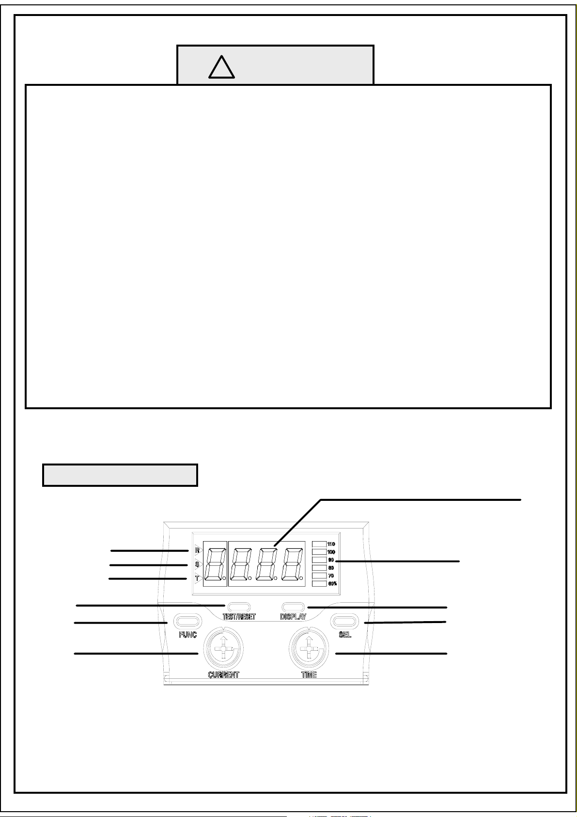
Display units
3-phase current/Trouble cause
R-phase
S-phase
T-phase
Test/Reset
Func
Load ratio
Display
Sel
Current
Time
2
Page 4
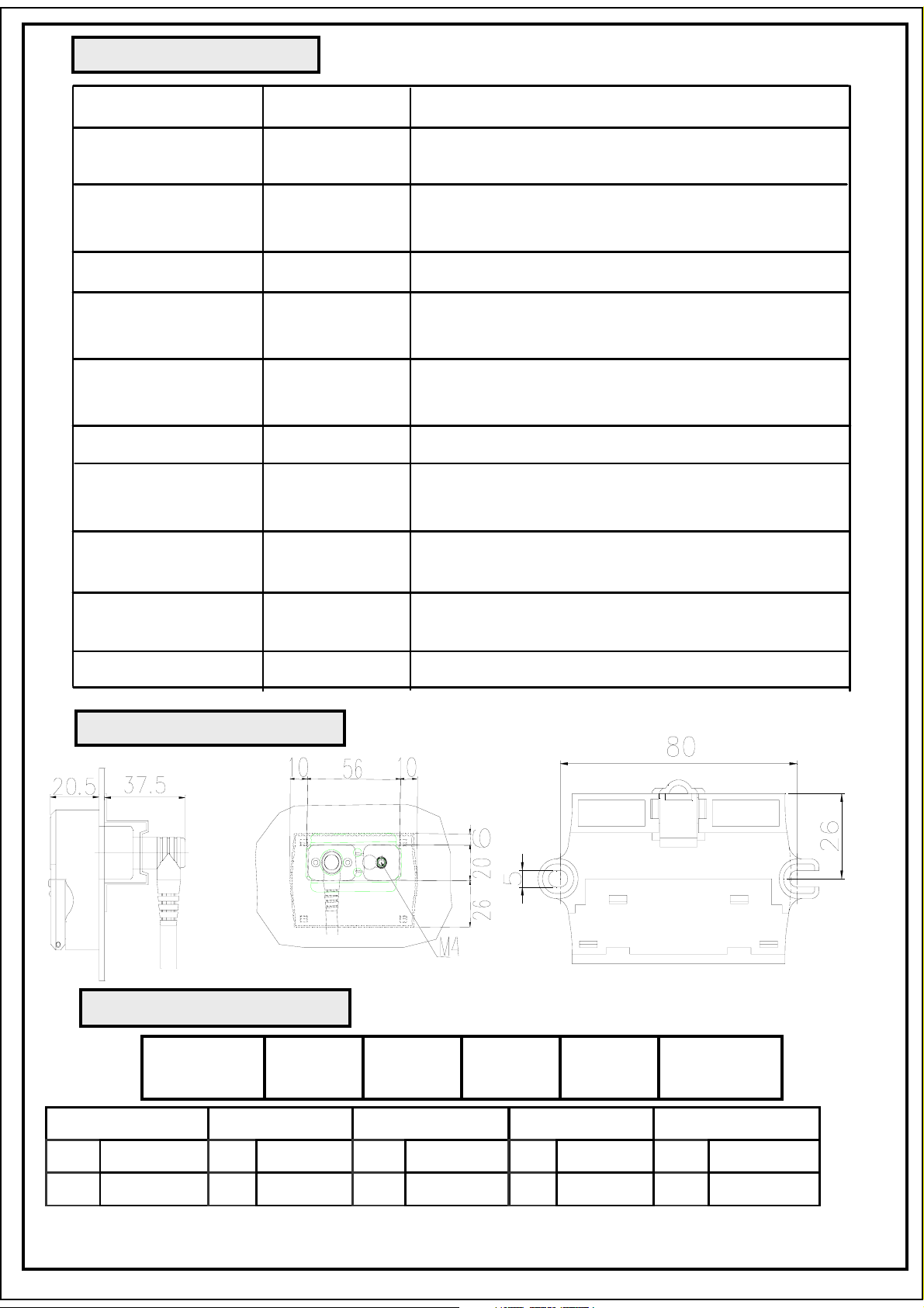
Trouble information
Protection show Description
More than set current
Overcurrent O-L
Within the set time
Undercurrent Und
Reverse phase r-P
Phase Loss P-F
Phase
P-F
unbalance
STALL StL
LOCK Loc
Instantaneous
Sho
Current
Ground fault g-F
Lower than the undercurrent set ratio
Within 3S
Within 0.1S
Over 70% of the rate of
unbalance : Within 3S
Over 50% of the rate of
unbalance : Within 5S
180% than seting current within 5S
More than the lock set current
ratio : Within 0.5S
More than the instantaneous set
current ratio : Within 0.1S
More than the set ground current
within the set time
Alert Bar-Leds
Installation Di mension
Ordering Method
DMP 06 S E Z 220
Load Ratio(60~110%)
Current
06600.5~6.0A
5.0~60A
Wiring
S Screw
T Tunnel
TYPE
E Separate
- Unify
3
OPTION
Z Ground
I Instant.
control Volt.
220 AC220V
110 AC110V
Page 5
☞ Refer to the catalog and home page(www.lsis.biz)
for further details.
* Head Office :
Yonsei Jaedan Severance Bldg.84-11 5ga,Namdaemun_ro,
Jung-gu,Seoul 120-749 Korea.
(TEL: 82-2-2034-4870 FAX: 82-2-2034-4713)
MEMO
7956 2121 001
4
 Loading...