


T7501
Total Control
With Zigbee
By:
Long Range Systems, Inc.
Long Range Systems UK Ltd | Link House | Leek Road | Milton | Stoke on Trent | Staffordshire | ST2 7AH |
01782 537000
www.lrspagers.co.uk | www.pagers.co | www.hospitalpagers.co.uk
User Manual
With
Installation, Warranty and Service
Information
September 2008
T7501UserInstructions

WARRANTY
Long Range Systems, Inc. warrants this product against any defects that are due
to faulty material or workmanship for a two-year period after the original date of
consumer purchase. This warranty does not include damage to the product
resulting from accident, misuse or improper electrical connection. If this product
should become defective within the warranty period, we will repair or replace with
equivalent product, free of charge. We will return your product, transportation
charges prepaid standard UPS Ground shipping mode, provided the product is
shipped prepaid to:
Long Range Systems, Inc., 4550 Excel Pkwy, Suite 200, Addison, TX 75001
No return or replacement can be received without prior authorization and the
proper RMA# posted to the outside of the shipping container.
This warranty gives you specific legal rights and you may also have rights that
vary from state to state.
© Copyright 2007, Long Range Systems, Inc. All Rights Reserved
This manual contains proprietary information of Long Range Systems, Inc. (LRS)
and is intended for use only by its employees or customers. None of the material
contained herein may be copied, reproduced, republished, downloaded,
displayed, posted, or transmitted in any form or by any means, including but not
limited to, electronic, mechanical, photocopying, recording, or otherwise without
the prior written permission of LRS. Additional copies of this manual may be
obtained by contacting LRS.
Screen displays, keyboard layouts, hardware descriptions, or software are
proprietary to LRS and are subject to copyright and other intellectual property
rights of LRS and shall be treated in accordance with the previous paragraph.
All attempts have been made to make the information in this document complete
and accurate. LRS is not responsible for any direct or indirect damages or loss
of business resulting from inaccuracies or omissions. Specifications and other
information contained within this document are subject to change without notice.
EU DECLARATION OF CONFORMITY
We, Long Range Systems hereby declare under our sole responsibility that the
T7501, TX-3B25, and KC-RT25 paging transmitters, and on-site pagers comply
with the essential requirements in the European RE&TTE Directive 1999/5/EC of
the European Parliament of the Council of 9 March 1999 on radio equipment and
telecommunication terminal equipment and the mutual recognition of their
conformity. The following standards were utilized:
ETS 300 224: 1998 EN 301 489-2: 2002
EN61000-3-2: 1998 EN 61000-3-3: 1995
EN 60950: 1992 with A1, A2, & A3.

T7501 Page i
Long Range Systems
Thank you for choosing Long Range Systems to provide your on-premise paging
solution. Please familiarize yourself and your staff with the contents of this
instruction in order to properly operate and maintain your system. For help
operating your system or for any service problems, please call :(800) 437-4996.
Keep this instruction in a safe place available to managers and key staff.
Contents
Chapter 1 General Information ............................................................... 1-1
Paging Functions .................................................................................... 1-1
Table Management ................................................................................. 1-1
On Site Operations .................................................................................................... 1-2
Off Site Operations .................................................................................................... 1-2
T7501 Keyboard Description ................................................................... 1-2
Primary Keypad ......................................................................................................... 1-2
Secondary Keypad ................................ ................................................................ .... 1-3
Chapter 2 Basic Guest and Staff Paging ................................................ 2-1
Direct Paging of On-Premise Guest Pagers ............................................ 2-1
Handing Out Pagers .................................................................................................. 2-1
Paging ....................................................................................................................... 2-1
On Premise and/or Cell Phone Paging from the Wait List ....................... 2-1
Handing Out Pagers .................................................................................................. 2-1
Paging from the Wait List - Basic View ...................................................................... 2-1
Paging Using Touch Screen or Keyboard/Mouse -Seating Management View ......... 2-2
Direct Staff Paging .................................................................................. 2-2
Staff Paging – Basic View ......................................................................................... 2-2
Staff Paging Using Touch Screen or Keyboard/Mouse - Seating Management View2-2
Preloaded Staff Pager Message Code List .............................................. 2-3
Chapter 3 Table and Wait List Management using only T7501 ............. 3-1
Basic Description .................................................................................... 3-1
Wait/Table List........................................................................................................... 3-1
Table Status .............................................................................................................. 3-1
Wait List .................................................................................................................... 3-1
Editing Wait List ...................................................................................... 3-2
Adding/Editing/Closing Tables at the T7501 ............................................................. 3-2
Wait List Management ............................................................................. 3-2
Add Guest to the Wait List ......................................................................................... 3-2
Edit Wait List ............................................................................................................. 3-3
Check Wait List Information ...................................................................................... 3-4
Change Wait List and Table Management Preferences. ........................................... 3-4
Chapter 4 Wait List and Table Management Using External Monitor ... 4-1
General ................................................................................................... 4-1
Visual Monitor ......................................................................................... 4-1
Restaurant Layout ................................................................................................ ..... 4-1
Seat Avail! ................................................................................................................. 4-1
Walk In ...................................................................................................................... 4-2
Reserve ..................................................................................................................... 4-2

Page ii T7501
Find Party .................................................................................................................. 4-2
Page ......................................................................................................................... 4-2
More .......................................................................................................................... 4-2
Zoom Out/IN ............................................................................................................. 4-2
Wait List .................................................................................................................... 4-2
Using the Visual Display ................................................................ .......... 4-3
Add Walk in Guests at the Host Stand ...................................................................... 4-3
Add Guest Off Premise. ............................................................................................ 4-3
Edits or Functional Changes Using the Mouse Pointer ............................................. 4-4
Edit Wait List ............................................................................................................. 4-4
Paging and Seating ................................................................................................... 4-5
Check Wait List Information ...................................................................................... 4-6
Changing Table Status ............................................................................ 4-6
Open Tables ............................................................................................................. 4-6
Close Tables ............................................................................................................. 4-6
Hold Tables ............................................................................................................... 4-6
Bus Tables ................................................................................................................ 4-6
Change Wait List and Table Management Preferences. .......................... 4-7
Editing Layout ......................................................................................... 4-7
Layout Screen ........................................................................................................... 4-7
Chapter 5 Installation and Setup ............................................................ 5-1
Basic Installation ..................................................................................... 5-1
T7501 Installation ...................................................................................................... 5-1
T7501 Optional Equipment installation .................................................... 5-2
External VGA Monitor Installation ............................................................................. 5-2
External Keyboard and Mouse .................................................................................. 5-2
Touch Screen Monitor ............................................................................................... 5-2
POS Printer ............................................................................................................... 5-3
Network Connection Requirements .......................................................................... 5-3
Basic System Tests ................................................................................. 5-4
Initial T7501 Power Up .............................................................................................. 5-4
On Premise Guest and Staff Pager Range Tests .................................... 5-4
T7501 Custom Setup .............................................................................. 5-5
Access Code ............................................................................................................. 5-5
Setup Guest and Staff Pager Functions .................................................................... 5-5
Set/Edit T7501 Alarms .............................................................................................. 5-6
Setup Wait List Functions ......................................................................................... 5-7
Alpha Pager Encryption Enable ................................................................................ 5-7
Chapter 6 Maintenance Functions .......................................................... 6-1
Select Table Management Functions ...................................................... 6-1
Setup Devices ................................ ......................................................... 6-1
Setup External VGA Monitor ................................................................... 6-1
Setup Network ......................................................................................... 6-2
View LAN Configuration ............................................................................................ 6-2
Setup LAN (use Wizard) ........................................................................................... 6-2
Setup LRSN .............................................................................................................. 6-2
Setup WPAN ............................................................................................................. 6-2
Firmware Update ..................................................................................... 6-3

T7501 Page iii
Review System Status ............................................................................ 6-3
Diagnostics.............................................................................................. 6-3
ID finder function ....................................................................................................... 6-3
Range Test ................................................................................................................ 6-4
Program Pagers ........................................................................................................ 6-4
Chapter 7 System Specifications............................................................ 7-1
Transmitter .............................................................................................. 7-1
Auxiliary TX/RX Devices (KeyCall, Table Genie, etc) .............................. 7-1
Battery Powered Pagers ......................................................................... 7-1
Rechargeable Pagers .............................................................................. 7-1
Chapter 8 Troubleshooting ................................ ..................................... 8-1
Display shows Nothing ............................................................................ 8-1
Pagers Don‘t Receive Pages ................................................................... 8-1
Battery Powered Pagers Don‘t Receive Pages ....................................... 8-1
Chapter 9 Service Questions and Answers ................................ ........... 9-1
Chapter 10 Click Ahead Seating ........................................................... 10-1
General Description ............................................................................... 10-1
Off Premise Operation ........................................................................... 10-1
Off Premise Operation ........................................................................... 10-2
On Premise Operation ........................................................................... 10-2
Chapter 11 Table Genie ......................................................................... 11-1
Setting Up T7501 for Table Genie Operation ........................................ 11-1
Setting Up and Associating the Table Genie with T7501 ....................... 11-3
Associating With Network Connectivity ................................................. 11-3
Mounting the Table Genie ..................................................................... 11-4
Using the Table Genie ........................................................................... 11-5
Using the Push For Service Monitor ...................................................... 11-6
Monitor .................................................................................................................... 11-6
Controls ................................................................................................................... 11-6
Alerts ....................................................................................................................... 11-7
Clearing an Order from the Service Monitor ............................................................ 11-7
Chapter 12 KeyCall ................................................................ ................ 12-1
Setup ..................................................................................................... 12-1
Typical Hardware Connection ................................................................................. 12-1
Minimum PC System Requirements ........................................................................ 12-1
Typical KeyCall Setup ............................................................................................. 12-2
Assign KeyCall Units to Tables ............................................................................... 12-3
Mounting the KeyCall .............................................................................................. 12-4
The KeyCallTX Program ....................................................................... 12-5
Setup Window ......................................................................................................... 12-5
Order Window ......................................................................................................... 12-8
Status Window ...................................................................................................... 12-12
Reports Window .................................................................................................... 12-13
Using The KeyCall............................................................................... 12-14
Starter Unit ............................................................................................................ 12-14

Page iv T7501
Clearing Unit ......................................................................................................... 12-14
Service Button ....................................................................................................... 12-14
Key Holder ............................................................................................................ 12-14
The KeyCall Keys ................................................................................ 12-14
Programming Key ................................................................................................. 12-14
Order Keys ............................................................................................................ 12-14
Troubleshooting................................................................................... 12-15
Re-Enter KeyCallTX Program ............................................................................... 12-15
Reassigning a KeyCall Unit in an Existing Install .................................................. 12-15
Low Battery Indicator – Order Window ................................................................. 12-15
No Connection – Order Window ........................................................................... 12-16
No T7500 Connection – Order Window ................................................................ 12-16
Chapter 13 Using The Staff Pagers ...................................................... 13-1
Messaging ............................................................................................. 13-1
Using the RX-E 4-Line Alpha Numeric Pager ........................................ 13-1
Menus ..................................................................................................................... 13-1
Selecting functions .................................................................................................. 13-1
Power On/Off .......................................................................................................... 13-1
Read Message ........................................................................................................ 13-2
Delete Messages .................................................................................................... 13-2
Time/Date Set ......................................................................................................... 13-2
View Calendar ............................................................... Error! Bookmark not defined.
Set Contrast ............................................................................................................ 13-2
Auto ON/OFF .......................................................................................................... 13-2
Set Keytone On/Off ................................................................................................. 13-3
Select Alert .............................................................................................................. 13-3
Stopwatch Function ...................................................... Error! Bookmark not defined.
Battery..................................................................................................................... 13-3
Programming .......................................................................................................... 13-3
Using the Star Pager ............................................................................. 13-4
Charging ................................................................................................................. 13-4
Programming .......................................................................................................... 13-4
Using the SP5 1-Line Rechargeable Alpha Numeric Pager ................... 13-5
Charging ................................................................................................................. 13-5
Menus ..................................................................................................................... 13-5
Settings ................................................................................................ ................... 13-6
Messages ................................................................................................................ 13-7
Time ........................................................................................................................ 13-7
Programming .......................................................................................................... 13-7
Chapter 14 Guest Pagers ...................................................................... 14-1
Messaging ............................................................................................. 14-1
Programming ......................................................................................... 14-1
Charging ................................................................................................ 14-1

T7501 Page 1-1
NETWORK INTERCONNECT
PATRON‘S
CELL PHONE
PATRON‘S CELL
PHONE PROVIDER
STAR PAGER
STAFF PAGERS
COASTER CALL
ADVERTEASER GUEST
PAGER
ALPHA MESSAGING STAFF
PAGERS
INTERNET
PROVIDER
INTERNET INQUIRYS AND
RESERVATIONS
T7501 BASE
STATION
CHAPTER 1 GENERAL INFORMATION
Paging Functions
Pages on site guest and Staff pagers directly through a radio transmitter
located in the base station.
Patron provided off site pagers (cell phones) are contacted by calling their
service through an Internet phone service.
Multiple Staff Pagers assigned to work groups can be paged as a group.
Groups can be reconfigured and pagers renumbered as necessary using the
transmitter.
Table Management
The T7501 keeps track of open tables, guests on the wait list, and waiting
times.
When tables are available, guests on the wait list are automatically paged
and removed from the list based on the size of their party, how long on list, or
other factors.
The wait list is compared to the number of names on the list, tables available,
and average time of service to inform patrons of wait time.
The list can be displayed for the guests on an external monitor.

Page 1-2 T7501
M1
A
M2
B
M3
C
M4
D
STAFF
E
1 J 2 K 3
L
4 N 5 O 6 P 7 R 8 S 9
T
0
PgUp
F
PgDn
G
Remove
H.
SETUP
I
INFO
M
EDIT
Q
Exit
Enter
BKSP
U
WAIT
V
W
Reserve
X
Y
Hold
Z
Seat
On Site Operations
On site wait list entries are is generated by entering the guest‘s name and arrival
time at either the base station or the roving hand held.
Off Site Operations
Off site wait list entries are added from an Internet query (Click Ahead Seating©)
that allows guests to check wait times and make reservations based on
estimated arrival time. Automatic telephone inquiries verify the reservations.
T7501 Keyboard Description
Before using the T7501, please read the following descriptions. Note that during
operation, keys are highlighted to indicate they are enabled and generally the
other keys will not function.
Primary Keypad

T7501 Page 1-3
Page
TBL Stat
Wait
List
SECONDARY
KEYPAD
M Keys The M (function) keys are the first row of keys under the display. The
operations of the keys change depending upon function on the screen (e.g., in
the Wait List function, the M keys correspond to manager call functions).
Number Keys - 1 through 0 are used to enter numeric data such as the pager
number or the selection in the setup mode.
Alpha Function – When entering alpha information (e.g., guest‘s names), all the
keys change to alpha characters (displayed on each key).
Staff Key - Used to page staff (or server) pagers.
Setup Key - Selects the setup menu used to change operating functions (e.g.,
system identification code).
Info Key – Displays wait information for parties on the list.
Edit Key – Enables updating of wait list functions, and setup functions.
Exit Key – Cancels a process and returns the system to a previous state.
BKSP Key – Backs the entry cursor to undo the last keystroke(s).
Enter Key – Completes a task.
Wait Key – Enables the wait list entry function.
Reserve Key – Opens a Reservation window on the display if Reservations
mode is set active.
Hold Key – Enables the table hold function.
Seat Key – Enables the guest seating function
Secondary Keypad
Alert Key (unmarked) – Lights to show that tables are
available for seating and blinks when attention is needed.
Page Key – Enables basic guest/staff paging function.
TBL Stat Key – Enables the table status edit function.
Wait List Key – Returns the system to the wait list
function. NOTE: this is the default function.


T7501 Page 2-1
CHAPTER 2 BASIC GUEST AND STAFF PAGING
Note: The T7501 is shipped with the paging defaults set for the most
commonly used configuration. To change, see Chapter 5.
Direct Paging of On-Premise Guest Pagers
Guests with LRS pagers can be directly paged from the T7501 keyboard. Be
sure pagers are charged and on.
Handing Out Pagers
Enter the guest party name into the waitlist and fill out information prompted by
the T7501 and enter the number of the guest pager handed out.
Paging
When ready to page the patron:
1. Select Page (on Secondary Keypad):
At the keyboard, press Page (Note: Page, number, and Staff keys light).
At a touch screen, touch Page then Guest.
2. Enter the desired Guest pager number at the Guest # screen.
3. Press Enter.
On Premise and/or Cell Phone Paging from the Wait List
Note: Two options are available on the T7501: The Basic view that shows only
a wait list and the Table Management view that shows a restaurant
layout and waitlist.
Handing Out Pagers
Enter the guest party name and information from the T7501 waitlist feature, and
enter the number of the guest pager handed out or collect the cell phone number.
When Click Ahead patrons check in they may change to a guest pager or use
the number they have already entered.
Cell phones can only be paged from the Wait List.
Cell phone paging requires an Internet network connection.
Paging from the Wait List - Basic View
Open Tables [alert key is on]
1. Use the up and down arrows to select the guest.
2. Press the Enter key.
3. At Seat Party select the table (use arrow keys).

Page 2-2 T7501
4. Press the Enter key (The selected table number in the left column shows the
page is made).
5. Press Seat key to remove the Guest from the list.
No Open Tables [alert key is off]
1. Use the up and down arrows to select the guest.
2. Press the Enter key.
3. At No Open Tables select YES (use arrow keys).
4. Press the Enter key (A ―—― in the left column shows the page is made).
5. Press Seat or Remove key to remove the Guest from the list.
Paging Using Touch Screen or Keyboard/Mouse -Seating
Management View
1. Select the guest to page from the waitlist using either the touch screen or the
keyboard/mouse.
2. From the Pie Selector chose options of Page, Seat, and Next to choose
different tables. (If no tables are open seating management will not let you
seat the party).
3. Choose Page to page the selected party or Seat to seat the party to remove
them from the list.
Direct Staff Paging
Note: Two options are available on the T7501: The Basic view that shows
only a wait list and the Table Management view that shows a restaurant
layout.
Staff Paging – Basic View
In Basic view staff pagers are directly paged from the T7501 keyboard.
1. Press the Staff key.
2. Enter the desired Staff pager number at the Staff # screen.
3. Press the Enter key.
4. Select a message
For Alpha pager select the preloaded message code (see code list below)
or press M1 to enter a custom message from the keyboard.
For Star pager select message code 0 – 9 or vibration code (M1 - M3).
5. Press Enter.
Staff Paging Using Touch Screen or Keyboard/Mouse - Seating
Management View
In Seating Management view, staff pagers are paged from the monitor using a
touch screen or keyboard/mouse.

T7501 Page 2-3
1. Select Page then Staff.
2. Enter the desired Staff pager number at the Staff # screen.
3. Select Enter.
4. Select a message
For Alpha pager select the preloaded message code (see code list below)
or press M1 to enter a custom message from the keyboard.
For Star pager select message code 0 – 9 or vibration code (M1 - M3) then
select one of the vibe settings.
5. Select Enter.
Preloaded Staff Pager Message Code List
Message codes send following preloaded messages to LRS Alpha (text) pagers.
Additional custom codes can be created (see Pagers in Installation and Setup
chapter).

Page 2-4 T7501
Pre Loaded Messages
Code
Message
Code
Message
Code
Message
000
Phone Call
026
Price check
052
Food
001
Sale Call
027
Department
053
Service
002
Manager
028
Cashier
054
Seat
003
Customer
029
Office
055
Check
004
Room
030
Table
056
Lobby
005
Visitor
031
Winner
057
Help
006
call Ext
032
Pickup
058
Restrm
007
MTG Room
033
Dock
059
Valet
008
Lane
034
You have mail
060
Car
009
Isle 035
Table ready
061
Bus
010
Void
036
No Special
062
Bay
011
Stamps
037
Hole
063
Lo batt
012
Change
038
Kitchen
064
error
013
Station
039
Bar
065
Exit
014
Machine
040
Door
066
Fax
015
operator
041
Survey
067
Host
016
Emergency
042
T-nnn Q-xx
068
Space
017
XX Minutes
043
Break nnnn
069
Location
018
Tee
044
Fire
070
Nursery
019
Pro Shop
045
Unit
071
Teller
020
Starter
046
Window
072
Office
021
Service Drive
047
Nurse
073
Buffet
022
Showroom
048
Register
074
Diap chng
023
Parked Call
049
Owner
075
Child cry
024
Voice Mail
050
Check
076
To nursery
025
Dressing RM
051
Drink

T7501 Page 3-1
CHAPTER 3 TABLE AND WAIT LIST
MANAGEMENT USING ONLY T7501
Basic Description
Wait/Table List
This shows to the host the table numbers available for seating. As tables
become ready, the guests on the wait list can be quickly seated. The host can
accurately inform guests as to their wait time by keeping track of when a guest
checks in, off premise reservations (e.g., Click Ahead Seating ©) table
availability, size of wait list, etc.
Wait List and Table Status are enabled at start up.
Most operating functions enable from this screen.
At any time, press Exit or Wait List to return to this screen.
Table Status
This section shows the availability of tables as a table number in the Open, Bus,
or Hold lists. Tables on these lists can be added or removed using the T7501
keypad (in TBL Stat mode). When tables are open, the Alert key on the T7501
is lit.
Wait List
This section shows the guests waiting for seating. Included in this list is;
I (information) – Blank indicates the guest is on site and checked in. N
indicates a guest is on the reservation list but has not checked in. A ―--" or
number indicates the guest has been paged.
Name - Is the identifying name of the party.
Sz (size of the party) – A number shows how many guests in the party.
Pgr – Number of the on-premise pager assigned (or M for mobile phone).
Quoted – The time quoted to the guest as wait time.
Actual - How long the patron has been waiting.
S/N (Smoking) – N is non smoking, S is smoking, and F is first available.
Pref (Seating preference) – Booth, Patio, or Window.
Special Needs – Special requests by guests (e.g., high chair). An * in the
Special Needs (Spl) column indicates if the customer has a special need.

Page 3-2 T7501
Editing Wait List
Adding/Editing/Closing Tables at the T7501
To add new tables to the Table Status section:
1. Press the TBL Stat key.
2. Use the arrow keys to select the table to edit
3. Press the EDIT key.
4. Enter the number of the table to change.
5. Press:
M1-Open - add a table on the open list.
M2-Close - remove a table from any list.
M3-Bus - add a table on the being bussed list.
M4-Hold - add a table to the hold list.
Setup- close all tables
Wait List Management
Add Guest to the Wait List
The following basic methods are used to add guests to the wait list.
Add Guest at the T7501 keypad.
1. Press the Wait key.
2. At the Wait List Entry Wizard Enter the Guest‘s preferences and press Enter.
3. Inform the Guest of the Estimated wait and press:
Enter to continue.
Exit to stop the entry and return to the Wait List display.
4. Continue entering the Guest Information and press Enter each time.
5. Select (with arrow keys)
Guest Pager if handing out an on-premise pager
Mobile Phone to use the guest‘s cell phone as a pager.
6. Enter a Guest pager # or a Mobile Phone # and press Enter (Note that the
guest is added to the wait list).
Add Guest Off Premise.
Adding guests to the Wait List from an off premise location is done through an
Internet connection. A specialized system (See Click Ahead Seating© Chapter)
maintains a database shared with the T7501. Guests can choose a restaurant
on the Internet, note the wait time and add their name to the list. Once added,
the name appears on the T7501 display. A ‘C’ in the information column
indicates the entry is off-premise and will be checking in. Once checked in, the
‗C’ disappears from the column. After arrival, the guest data can be edited.

T7501 Page 3-3
Edit Wait List
General Editing
All of the items for a guest on the wait list may be edited at the T7501. To edit a
guest‘s information:
1. Use the arrow keys to select the name to edit.
2. Press the Edit key.
3. Use the Arrow keys and the M keys to scroll to the item(s) to edit.
4. Choose Yes to remove and press Enter.
5. The field will show the current data. Edit the field.
6. Press the Enter key.
7. Repeat steps 3 through 6 for all fields to change.
8. When finished, press the Exit key.
Editing Off-Premise Arrivals
It is desirable to check the information for guests that have been added offpremise. A ‘C’ in the information column indicates the entry is off-premise. To
edit a guest‘s information:
1. Use the arrow keys to select the name to edit.
2. Press the Edit key.
3. At the arrival menu, either issue an on-premise pager or verify the guest‘s cell
phone number.
4. Press Exit to return to the Wait List screen.
Removing or Changing Guest List Position on Wait List
Guests are removed from or their order changed on the list with direct removal or
with paging and seating.
Direct Removal
To remove a guest from the wait list without paging and seating (guest decided
not to wait; the wait has become more casual, etc.). To remove a guest:
1. Use the arrow keys to select the name to remove.
2. Press the Remove key.
3. Select Remove.
4. Press Enter key.
Change Order on List
In some cases it is desired to change the position of a guest on the wait list
(guest is delayed; another party is late, etc.). To move a guest:
1. Use the arrow keys to select the name to move.
2. Press the Remove key
3. Select Move Down the list (and amount of time).
4. Press Enter key

Page 3-4 T7501
Normal Paging and Seating
Normally a guest is removed from the wait list after being paged and seated. To
page and seat a guest:
1. Use the arrow keys to select the name to seat.
2. Press the Enter key.
If a table is available select the table.
If a table is not available, select Yes (to page anyway) or No to return to the
list without paging.
3. Press the Enter key again
The guest is paged
The - - symbol appears in the I (info) column (Note: The Pager Number
would be seen in Seating Management View.)
4. When the guest arrives, press the Seat key (the guest is removed).
Check Wait List Information
A guest‘s wait list information can be viewed in a more standard format. Some
additional information such as Frequent Diner Number or Special Needs can also
be seen.
To view wait list information:
1. Use the arrow keys to select the name to view.
2. Press the Info key.
3. Press the Exit key when finished.
Change Wait List and Table Management Preferences.
To change the items displayed on the wait list and table management display,
refer to the Installation and Setup chapter.

T7501 Page 4-1
R Roger 1 15 Booth 16 2:50
23 John 3 M 18 17
Albert 4 212 Window 19 4
C Jim 2 M 21 1
I Name Sz Pgr Pref W Q
Seat Avail!
Zoom In
Walk-
Reserv
Find Party
More…
Page
MANAGEMENT USING EXTERNAL MONITOR
General
Table management is a visual display of the tables available for seating. Basic
operation is similar to the Basic Wait List Management; the difference is the
visual display utilizes an external monitor, keyboard, and mouse (or touch
screen).
Visual Monitor
The left portion of the display shows the Wait list. The right portion shows the
restaurant layout. The buttons across the bottom access various functions.
Restaurant Layout
The panel to the right of the wait list shows the layout of the restaurant. The
portion shown in the grid is the area that will be magnified if zoomed in (either by
Touchscreen or mouse).
CHAPTER 4 WAIT LIST AND TABLE
Seat Avail!
Button that indicates a table is available for selected parties. If a party is
selected and no table is available the button is grayed out. If a table is available,
the button is green. This button can be used for seating guests.

Page 4-2 T7501
Walk In
Pops up a wizard for collecting on premise guest data and assigning a pager.
Reserve
Pops up a wizard for collecting off premise guest data.
Find Party
Pop up menu to find parties that are Waiting, have a Reservation, are Seated, or
have cancelled (history). Used to check on or change the status of guests.
Page
Pop up menu for direct paging of managers, staff, or guests.
More
Pop up menu for editing tables and setup functions.
Zoom Out/IN
Zoom OUT/IN allows zooming to a more detailed view of the restaurant. Zoom in
is accomplished by either pressing the Zoom IN button or clicking the area
desired with the mouse pointer. Zoom OUT is only accomplished with the button.
When zoomed IN, the arrows () on the display move the view to the next
portion of the restaurant. When zoomed OUT the whole restaurant is shown.
Wait List
The panel on the left shows the guests waiting for seating. Included in this list is;
I (information) – Blank indicates the guest is on site and checked in.
R indicates a guest on the reservation list has not checked in.
C indicates a Click Ahead guest reservation has not checked in.
# Number indicates the table assigned to a paged guest.
Name - Is the identifying name of the party.
Sz (size of the party) – A number shows how many guests in the party.
Pgr – Number of the on-premise pager assigned (or M for mobile phone).
Pref (Seating preference) – Booth, Patio, or Window.
S/N (Smoking) – N is non smoking, S is smoking, and F is first available.
Special Needs – Special requests by guests (e.g., high chair).
W (wait) - How long the patron has waited.
Q (quoted) – Wait time patron was quoted Note: The wait list entry changes
color if a party waits longer than quoted.

T7501 Page 4-3
R Roger 1 15 Booth 16 2:50
John 3 M 18 17
Albert 4 212 Window 19 4
C Jim 2 M 21 1
31 32 33 34 35
21
22 23
24
25
I Name Sz Pgr Pref A W
Seat Avail!
Zoom Out
Walk-
Reserv
Find Party
More…
Page
Using the Visual Display
Add Walk in Guests at the Host Stand
1. Press the Wait (T7501 keypad), F5 (keyboard), or Walk-in (touch screen)
2. At the Wait List Entry Wizard Enter the Guest‘s preferences and press Enter.
3. Inform the Guest of the Estimated wait and press:
Enter to continue.
Exit to stop the entry and return to the Wait List display.
4. Continue entering the Guest Information and press Enter each time.
5. Select
Guest Pager if handing out an on-premise pager
Mobile Phone to use the guest‘s cell phone as a pager.
6. Enter a Guest pager # or a Mobile Phone # and press Enter (Note that the
guest is added to the wait list).
Add Guest Off Premise.
Using Click-Ahead Seating
Adding guest to the Wait List from an off premise location is done through an
Internet connection. A specialized system (See Click Ahead Seating© Chapter)
maintains a database shared with the T7501. Guests can choose a restaurant
on the Internet, note the wait time and add their name to the list. Once added,
the name appears on the T7501 display. A C in the information column indicates
the entry is off-premise and will be checking in. Once checked-in, the C
disappears from the column. After arrival, the guest data can be edited.

Page 4-4 T7501
Page
Next >
Seat
< Prev
X
One Click
Move
Down
Edit
Remove
Info
X
Two Clicks
Call In Reservations
The Hostess can take Call-in Reservations to add guest to the Wait List. The
T7501 maintains a database. The procedure is the same as for a walk-in. Once
added, the name appears with an R in the information column to indicate the
entry is off-premise and will be checking in. Once checked in, the R disappears
from the column.
Edits or Functional Changes Using the Mouse Pointer
All editing or operational functions can be performed with the Touchscreen,
mouse pointer, and keyboard. Select an Item to edit and click once or twice,
depending on function. A pop up disk will allow selection of the function.
Example: A change in status of someone on the wait list.
Edit Wait List
All of the items for a guest on the wait list may be edited at the T7501 or the
Hostess Keyboard (recommended). The following directions are based on using
the mouse/keyboard. Refer to the previous chapter for T7501 Editing.
General Editing
To edit a guest‘s information:
Note: A C or an R in the information column indicates the guest has not yet
arrived.
1. To edit a guest‘s information Double click on the name to edit.
2. Select Edit at the pop up disk.
3. A pop up window shows the current data. Change the desired information.
4. Click the Apply button (or Cancel button if no changes are made).
Acknowledge a Reservation or Click Ahead Guest Arrival
To change a guest‘s status to arrived:
Note: A C or an R in the information column indicates the guest has not yet
arrived.
1. Single click on arrived guest‘s name.

T7501 Page 4-5
2. At the Pop Up disk:
Select Arrived and the C or R will be removed from the I column.
Select New Phone if the guest will be using a cell phone as a pager and
the number is different from the number already in the system.
Select Give Pager if the guest will be using an LRS Guest pager.
Remove or Change Guest List Position on Wait List
Guests on the Wait List are removed or their order changed by direct removal or
by paging and seating.
Direct Removal
To remove a guest from the wait list without paging and seating (guest decided
not to wait; the wait has become more casual, etc.):
1. Double click on the name to remove.
2. Select Remove at the pop up disk.
Note: If a guest is removed by mistake, Use the Find Party/Cancellations
procedure to restore.
Change Order on List
In some cases it is necessary to change the position of a guest on the wait list
(guest is delayed; another party is late, etc.). To move a guest:
1. Double click on the name to move.
2. Select Move Down at the pop up disk.
3. Enter the number of minutes.
4. Select Enter to make changes.
Paging and Seating
Normally a guest is removed from the wait list after being paged and seated. To
page and seat a guest:
1. Single click on the name to page or seat.
2. If a table(s) is available.
The Page/Seat disk pops up.
A table in the dining area is highlighted in red.
Selecting Next > will highlight other available tables.
3. Select Page to page the guest.
The selected table number appears in the guest list I column
A page symbol appears at the table.
4. Select the Guest # and at the pop up disk select Seat.

Page 4-6 T7501
Check Wait List Information
A guest‘s wait list information can be viewed in a more standard format. Some
additional information such as Frequent Diner Number or Special Occasion can
also be seen.
To view wait list information:
1. Double click on the name to check.
2. Select Info at the pop up disk.
3. Click on the X when finished.
Changing Table Status
Open tables are shown green, Closed are red, Bussed are orange, Held are
white, and Drop Checked are yellow. Table status is changed in several ways.
Note: All of the tables may be opened or closed (seated) at one time by
selecting the MORE button and then the appropriate choice.
Open Tables
1. Click on the table.
2. Select Edit Table.
3. Select Open.
Close Tables
1. Select a guest to seat. Note: If no guests are on the list the table will close
anyway.
2. Click on the table.
3. Select Edit Table.
4. Select Seat.
Hold Tables
1. Select the table.
2. Select Edit Table.
3. Select Hold.
Bus Tables
1. Select the table.
2. Select Edit Table.
3. Select Bus.

T7501 Page 4-7
31 32 33 34 35
21
22 23
24
25
Delete
Default
tools
Done!
Table
Pointer
Table # Type Size
caption
Remove
Stand
Door
Add
Wall
Booth
Floor Plans
111
booth
6
Change Wait List and Table Management Preferences.
To change the items displayed on the wait list and table management display,
refer to the Installation and Setup chapter.
Editing Layout
In a new installation or changing a current layout the process is the same.
Make a sketch or drawn floor plan layout.
Select the Layout Menu by pressing M1 (T7501) or F1 (external keyboard)
Add, remove, or edit walls and tables.
Press DONE when finished.
Call LRS if additional Instructions are needed.
Layout Screen
When selected the layout screen is shown. This screen will show the existing
layout. All components can be added, edited, deleted or moved.
Pointer
The pointer shows the position of the cursor. In this mode single click on a table
or wall on time to reposition. Double click on a table to edit the table definition.
Click on the arrow points to move to the next area.

Page 4-8 T7501
Table/Booth Addition, Editing, Removal
The Layout Editor changes the cursor to a + when the table button is selected.
Position the cursor where an added table/booth is desired and click. A pop up
menu allows selection of a table/booth type, size, and orientation. While in this
mode, all tables and booths can be positioned. To remove a table/booth, select
and click the delete button. Single click on the table icon and use the menus at
the bottom of the screen to change the number and size data.
Wall Addition, Editing, Removal
The Layout Editor changes the cursor to a + when the wall tool is selected.
Position the cursor where the beginning of an added wall is desired and click.
Move the cursor to the next position for the wall and click (note this can be
several turns and angles). When finished, select the Pointer button note, the line
segment will follow to the button but will not be added). While in this mode, all
walls can be positioned. To remove a wall, select and click the delete button.
Door Addition, Editing, Removal (not currently implemented)
The cursor changes to a +. Position the cursor where a door is desired and
click. A pop up menu allows selection of a door size, and orientation. To remove
a door, select and click the delete button.
Stand Addition, Editing, Removal (not currently implemented)
The cursor changes to a +. Position the cursor where a stand is desired and
click. A pop up menu allows selection of a stand size, and orientation. While in
this mode, all tables and stands can be positioned. To remove a stand, select
and click the delete button.
Caption Addition, Editing, Removal (not currently implemented)
The cursor changes to a +. Position the cursor where a caption desired and
click. A pop up menu allows addition of text from the keyboard. To remove a
caption, select and click the delete button.
Floor Plans (not currently implemented)
Once started or completed, a floor plan can be named for retrieval later. Click
ADD and follow the instructions. To delete a plan, select the title and click
DELETE.

T7501 Page 5-1
NETWORK
INTERCONNECT
9 VAC
POWER
ADAPTER
110 VAC
ELECTRICAL
SUPPLY
ANTENNA
T7501/TRANSMITTER
USB
PORTS
USB MOUSE (NOT SUPPLIED)
USB KEYBOARD (NOT SUPPLIED)
PC MONITOR (NOT SUPPLIED)
Note: If using a touch
screen monitor, the
data cable is
connected and the
USB mouse and
keyboard are not.
CHAPTER 5 INSTALLATION AND SETUP
Basic Installation
T7501 Installation
CAUTION: Do not connect any other devices to the T7501 power
connection. The unit requires a separate power supply.
CAUTION: Do not mount the T7501 antenna near any large metal objects.
1. Unwrap all T7501 base station components.
2. Connect the 3‖ angled antenna onto the connector on the back of the unit with
the antenna perpendicular to the ground.
3. Locate the unit convenient to 110V power and network outlet(s).
4. Plug the power supply into standard 110V outlet and the barrel connector end
into the T7501 9v power jack (a surge protector is recommended).
5. Connect network, external keyboard, and monitor as required. See page 5-2
of this section.

Page 5-2 T7501
T7501 Optional Equipment installation
External VGA Monitor Installation
For basic wait list operation, an external video monitor is recommended. The
monitor can be any standard PC monitor that connects to a standard VGA
connector. The VGA monitor connector is on the rear of the T7501 Base Station.
Guest View Monitor Setup
The default setup is for guest view of the wait list. In this mode advertising data
can be cycled across the screen. See Adding Guest View Advertising.
Hostess View Monitor Setup
The Hostess view is a larger view of the standard built in monitor. This view is
selected a follows:
1. Press Setup key.
2. Enter the manager access code.
3. Select Display.
4. Select Main Display.
5. Select External Display and then press Enter.
6. Press Exit key and Accept Changes with Enter key.
External Keyboard and Mouse
For some system features an external keyboard and/or mouse is recommended.
Three USB ports are provided for connection of a PC standard USB keyboard
and a USB mouse. The keyboard automatically operates, however the mouse
must be enabled. To enable the mouse:
1. Press Setup key.
2. Enter the manager access code.
3. Select Devices.
4. Select Mouse.
5. Select Mouse Type and then press Enter.
6. Press Exit key and Accept Changes with Enter key.
Note: Plug only one device into the front USB Ports. If using two USB devices,
plug one into the rear USB port.
Touch Screen Monitor
The touch screen monitor is an alternate to using an external keyboard and
mouse. The video input is connected to the VGA port. The touch control input is
connected to one of the three USB ports (usually the one near the power
connector). Once connected the touch screen features automatically operate

T7501 Page 5-3
(first time setup will enable a calibrate function). If necessary to manually
calibrate monitor features:
1. Press Setup key.
2. Enter the manager access code.
3. Select Devices.
4. Select Touch Screen.
5. Select Calibrate and then press Enter.
6. Press Exit key and Accept Changes with Enter key.
POS Printer
1. The POS printer is used to print out table assignments in wait management
operation. A printout of the party name and table assignment is given to the
seating personnel. The Printer can be tied to the LAN network or a direct
crossover via the Ethernet port on the T7501. The T7501 supports the Epson
POS format. If a printer is to be used, please contact LRS support during
normal business hours for specification and installation instruction
Network Connection Requirements
For systems using network communications (e.g., systems using Click Ahead
Seating©), a 10/100 BaseT connection must be available. The DHCP protocol
will normally locate the IP address automatically. If the network does not support
DHCP, a local network administrator may be required to assign a static IP
address. Follow the instructions below or call LRS for instruction on this
procedure
Ethernet Requirements
A live (connected) Ethernet cable with Internet access.
OUTGOING access to TCP port 80.
DHCP or Static IP Server Addresses
DHCP
The T7501 default is set for DHCP. DHCP usually automatically sets up the IP
address, masks, DNS servers, and gateways. Some systems do not support
DHCP and require a static IP address.
Static IP Setup
If Static IP is required, a systems administrator should set it up:
IP address
Subnet mask
Default Gateway
At least 1 DNS server (if only 1 DNS server is on the network, populate both
fields with one DNS address)

Page 5-4 T7501
To Setup T7501 Static IP
1. Press Setup Key
2. Enter access code 2 9 1 6 3 and press Enter.
3. Select Network (Icon or from List).
4. Select LAN Wizard (Icon or from List).
5. Select Static and press Enter key.
6. Enter:
IP address
Subnet mask
Default Gateway
7. Press Enter
8. Setup:
Primary DNS server
Secondary DNS server
9. Press Enter
10. Cycle the 9Vac power
Basic System Tests
Initial T7501 Power Up
When power is applied, the T7501 transmitter begins the initialization steps:
1. Screen is blank while the keyboard lights flash.
2. The screen shows a booting sequence.
Note: If using Click Ahead seating the time will be automatically set from the
Internet service. If not a pop up screen requires the local time to be set.
3. The Wait List and Table Status screen appears
4. The INFO, EDIT, Up Arrow, Down Arrow, and Wait List Buttons are lit.
5. The unit is ready for operation.
On Premise Guest and Staff Pager Range Tests
NOTE: Access Code is needed for Setup functions (T7501 Custom Setup).
Perform this test to see if the pagers can be paged in all operating locations.
Although range may vary slightly during busy times, this generally shows where
guests can roam. Be sure pagers are fully charged and/or have good batteries
and are on. Do not perform a range test when guests have pagers because
they will flash all at once. To begin test:
1. Press Setup.
2. Select System,
3. Select Diagnostics,
4. Select Range Test
5. Press Enter to start the test and Exit to cancel.

T7501 Page 5-5
6. Take 2 or 3 charged pagers and walk around the area. The pagers flash
about once every 3-4 seconds.
7. The point where the pager does not flash consistently is the maximum range.
To increase or decrease the range, see Prog TX Power. Repeat test until the
range is acceptable.
8. Press Enter to end the test.
T7501 Custom Setup
Access Code
NOTE: Access Code is needed for Setup functions.
To reduce tampering with critical settings functions that adjust paging and
operational preferences the T7501 is protected by access codes.
Access levels are Service (Highest), Admin, and Manager (lowest).
Each level allows privilege to the functions below but not above.
Access codes for Admin and Manager are usually set at the Service level.
To set access codes:
1. Press Setup.
2. Select System, and then select Access Codes.
3. Select the level to change (service, admin, or manager) (Note: only the access
levels appropriate for the entered code will be displayed)
4. Enter the access code appropriate for the selected level.
5. Press Enter.
6. Enter the new access code.
7. Press Enter.
8. Press Exit to return to the main menu screen.
Setup Guest and Staff Pager Functions
NOTE: Access Code is needed for Setup functions (T7501 Custom Setup).
These functions effect the operation of the pagers.
1. Press Setup
2. Select Pagers and press Enter.
3. Setup from Pager list
4. Select item from list and press Enter.
5. Make desired changes,
6. At end press Exit
7. Select Yes to accept changes
8. Press Enter.

Page 5-6 T7501
Guest Paging Mode – Determines how the
guest pager will alert when paged
(vibration, flash type, etc).
Staff Paging Mode– Determines how the
staff pager will alert when paged (vibration,
sound, etc).
Group Paging – Enables or disables Group
Paging for Text pagers.
M1 – M4 Assignment – Assigns manger
pagers to buttons M1 – M4.
Edit Alarms – See Setting Alarms.
POCSAG Pager Type – Default Alpha
(Text). Some systems may use Numeric
only pagers.
POCSAG Start – In systems with mixed
staff pagers will set the crossover
number between Alpha and
rechargeable pagers.
POCSAG All Page – Sets the number that
will be used to pages all Alpha Staff
Pagers (default 911).
Custom Messages – Create unique
Alpha pager messages
Select message to Edit/Add.
Enter the Text (all lower case).
Note the number assigned to use to
send custom text to pagers.
Press Enter to save.
Pager List
Set/Edit T7501 Alarms
NOTE: Access Code is needed for Setup functions.
Pagers can be alarmed to alert staff of regular operations that must be
performed.
1. Press Setup.
2. Select Pagers and press Enter.
3. Select Edit Alarms and press Enter.
4. Highlight the alarm to edit or select New.
5. Select the Alarm type
Single Shot – after one time the page will be cleared and not repeated.
Interval – the page will be repeated at a regular interval (e.g., 30 minutes).
Daily – the alarm will be repeated at the same time each day.
Weekly – the alarm will be repeated at the same time on a selected day
each week.
6. Select the time and/or day for the alarm.
7. Enter the pager number to be called (this will be a staff pager).
8. Enter the message number to be sent (from the list of messages)
9. If the message is correct in the Final Message window, press Enter to accept.

T7501 Page 5-7
Smoking – Enable Guests smoking choice.
Table Preferences – Enable Guest table
preferences.
Edit Table Preferences – Set types of tables
available for Guest choices.
Occasion – Enable Guest occasion types.
Edit Occasion Descriptions – Set types of
occasions available for Guest choices.
Frequent Diner – Enables use of frequent
diner numbers.
Print Table Ticket – Enables or disables use
of optional table ticket printer.
Click Ahead Seating – Enables or
disables Click Ahead Seating Feature.
Party Warn Threshold – Sets the
number of people in a party to alert the
staff of larger than normal groups.
Party Warn Limit – How far down the list
to look for a larger than normal party.
Purge Local Backup – Clears the day‘s
wait list (done at start of or end of daily
operations).
Setup Wait List Functions
NOTE: Access Code is needed for Setup functions.
The Wait list functions are modified at the Wait List menu.
1. Press Setup.
2. Select Wait List.
3. Press Enter.
4. Select function from the following list
Alpha Pager Encryption Enable
NOTE: Manager Access Code is needed for encryption functions.
Encryption is an automatic feature built into the pager designed to meet HIPAA
security requirements. It is keyed by settings and codes on LRS transmitters.
To enable encryption:
1. Press Setup.
2. Select Setup.
3. Select Encryption.
4. Enable Encryption and enter a pass phrase.
5. Press Ok.
6. At end press Exit.
7. Select Yes to accept changes.
8. Reprogram all of the Alpha Pagers to be used with this system.


T7501 Page 6-1
Key Call – Sets the basic KeyCall functions.
These settings are forwarded to the TX units
periodically.
Beep Volume – from 0 (off) to 10 (max).
Beep on Error (ON/OFF).
Associate – used when new TX units are
installed in the system. See Key Call
Chapter for setup.
T900 – Used when new T900‘s are added to
the system. Note: T900 cannot be used on
a T7501 Zigbee system.
Printer – Used when the optional table
ticket printer is used with the system. This
printer is connected through a network
interface.
Printer address – selects the IP address
of the printer. This address is found by
a turn on feature of the printer (see
printer manual).
Printer type – selects from a list of
approved printers. Currently only the
Epson POS is supported.
CHAPTER 6 MAINTENANCE FUNCTIONS
These functions are used to locate problems or to ―tune up a system for
maximum performance in your area.
Select Table Management Functions
The Table Management functions are modified at the Wait List menu. This is an
LRS Only function.
Setup Devices
NOTE: Access Code is needed for Setup functions.
External Devices used with the T7501 are Key Call, Table Genie, and Printer.
1. Press Setup.
2. Select Devices.
3. Press Enter.
4. Select function from the following list
5. Select item from list and press Enter.
6. Make desired changes.
7. At end press Exit
8. Select Yes to accept changes
9. Press Enter.
Setup External VGA Monitor
NOTE: Access Code is needed for Setup functions.
The T7501 Normal function drives an external VGA monitor that shows portions
of the Wait List and periodic Advertisements for waiting guests. The external
display can be set to replace the function of the LCD display on the T7501.
1. Press Setup.
2. Select Display.
3. Press Enter.
4. Select function from the following list

Page 6-2 T7501
LCD – Sets T7501 LCD display contrast and brightness
Guest VGA – Sets the display preferences to the Guest VGA Monitor
VGA Image Cycle Time is the time in seconds different images are displayed.
VGA Images – Used to add and remove images that cycle on the Guest monitor.
Main Display – Selects to use the Local LCD or the External VGA Monitor as the primary
T7501 display.
5. Make desired changes.
6. At end press Exit.
7. Select Yes to accept changes.
8. Press Enter.
Setup Network
NOTE: Access Code is needed for Setup functions.
The Local Area Network (LAN) connects the T7501 to the Internet and other
devices. To set up LAN, a System administrator is recommended.
View LAN Configuration
1. Press Setup.
2. Select Network.
3. Select LAN Config.
4. The current LAN configuration is displayed.
Setup LAN (use Wizard)
1. Press Setup.
2. Select Network.
3. Select the LAN Wizard.
4. Follow the instructions and set up the LAN.
Setup LRSN
This is an LRS Only Configuration.
Setup WPAN
WPAN is the wireless network configuration for using LRS Zigbee devices. Use
this function only after receiving instructions from LRS customer service.
1. Press Setup.
2. Select WPAN.
3. Select:
Config to view the current configuration.
Associate to associate am LRS Zigbee device to T7501 (see T7501
Communication setup in this chapter).
Tuning to view the tuning configuration.

T7501 Page 6-3
Firmware Update
NOTE: Access Code is needed for Setup functions.
Periodically firmware updates may be required to allow the T7501 to function
more efficiently or add new features. If the unit is connected to the Internet these
upgrades can be accomplished without having to send the unit to the
manufacturer or have a software professional do the job.
Note: Because updates will temporarily interrupt service, perform this task only
when the unit is not in current use. Once begun the update must be
allowed to complete.
1. Press Setup.
2. Use the Arrow keys to highlight Update.
3. Press Enter.
4. When the Updates screen appears, press Enter.
5. Follow instructions on the various pop up screens until update is complete.
Review System Status
The system status is used to review the operational and program settings in the
unit. If properly authorized (see authorization code) the system settings shown
in this display can be altered.
Diagnostics
NOTE: Access Code is needed for Setup functions.
These functions are used to determine and correct Guest/Staff paging problems.
ID finder function
ID finder searches the available system ID‘s if the ID of the system is not known.
1. Remove 2 or 3 pagers or coasters from the charger or turn on some batterypowered pagers.
2. Press Setup.
3. Select Diagnostics.
4. Select ID Finder.
5. Press Enter to begin and the unit searches for the entire ID = 0 codes.
6. When it has paged all of the codes it asks ―Did Your Pager Work?‖
If the pagers respond, select Yes and the unit will be set to this ID.
If none of the pagers respond, select No and the unit tries the next ID.
Continue until the correct ID is found.
If the unit cycles back to ID 0 without the pagers responding, call LRS.

Page 6-4 T7501
Range Test
This test determines if the pagers can be paged in all operating locations.
Although range may vary slightly during busy times, this generally shows where
guests can roam. Do not perform a range test when guests have pagers
because they will flash all at once. To begin test:
1. Press Setup.
2. Select System.
3. Select Diagnostics.
4. Select Range Test.
5. Press Enter to start the test and Exit to cancel.
6. Take 2 or 3 charged pagers and walk around the area. The pagers flash
about once every 3-4 seconds.
7. The point where the pager does not flash consistently is the maximum range.
8. Press Enter to end the test.
Program Pagers
LRS Guest and Staff pagers can have their identification number and system ID
changed using the T7501. To Program pagers:
Pizzas, Lobsters, and AdverTeaser Guest Pagers
1. Press Setup
2. Select System
3. Select Diagnostics
4. Select Program Pagers
5. Press Enter to start.
6. Select Coaster and Enter.
7. Select:
Pager IDs if programming individual pagers
Broadcast system ID if changing all the pagers to a new System or turning
all their vibrators on or off.
8. Press Enter.
9. Select vibrator on or off and press Enter.
10. Enter the number to use on the pager and press Enter.
11. Remove pager from the charger (all pagers if using Broadcast function) and
wait until they stop flashing/vibrating then press Enter.
12. Repeat with all pagers to be programmed.
Rechargeable (Star) Staff Pagers
1. Press Setup.
2. Select System.
3. Select Diagnostics
4. Select Program Pagers

T7501 Page 6-5
5. Press Enter to start.
6. Select Star and Enter.
7. Select Manager and Enter.
8. Select:
Pager IDs if programming individual pagers
Broadcast system ID if changing all the pagers to a new System or turning
all their vibrators on or off.
9. Press Enter.
10. Select vibrator on or off and press Enter.
11. Enter the number to use on the pager and press Enter
12. Remove pager from the charger (all pagers if using Broadcast function) and
wait until they stop flashing/vibrating then press Enter
13. Repeat with all pagers to be programmed
Battery Operated Alphanumeric Staff Pagers
1. Press Setup.
2. Select System
3. Select Diagnostics
4. Select Program Pagers
5. Press Enter to start.
6. Select Alphanumeric and Enter.
7. Enter the number to use on the pager and press Enter.
8. If the pager is on turn it off.
9. Turn the pager on and wait until it stops beeping.
10. If the pager responded properly, repeat with all pagers to be programmed.


T7501 Page 7-1
CHAPTER 7 SYSTEM SPECIFICATIONS
Transmitter
Notice: Operation is subject to the following:
This device may not cause interference
This device will accept any interference including interference that may
cause undesired operation of the unit.
Notice: To reduce potential radio interference to other users, the antenna type
and gain is set so that the equivalent isotropically radiated power (EIRP) is
not more than required for successful communication.
Required voltage: One 110V outlet for the T7501 keypad.
Operating Frequency / Radiated Power:
467.750-MHz / 1W (FCC Part 90)
2.4 GHz ISM Band / 100mW (FCC Part 15)
Operating Range: Dependent upon pagers used
Broadband Connection: Cat 5 connection to 10/100BaseT Router connected
to Internet.
Auxiliary TX/RX Devices (KeyCall, Table Genie, etc)
Operating Frequency: 2.4GHz ISM Band (US)
Required voltage: Device Dependent
Battery Powered Pagers
Required voltage: One AAA Alkaline battery for the pager.
Rechargeable Pagers
Required voltage: (1) 110V outlets for pager chargers
Batteries: Nickel Metal Hydride (NiMH). Rechargeable. Lifetime of Batteries:
Approximately 3-5 years
Battery life of pager: Approximately 48 hours (depends on how often they are
paged). Recharge time: 24 hours minimum from completely ―dead‖.


T7501 Page 8-1
CHAPTER 8 TROUBLESHOOTING
Display shows Nothing
Be sure power supply is plugged in.
If yes
– Be sure power supply is good (substitute).
– Be sure the wall circuit is on.
– Unplug and re-plug a few times to be sure the unit doesn‘t need a reset.
If no – plug it in
Remedy
If power supply is good call LRS to get a new transmitter
If power supply is bad call LRS to get a new power supply.
Pagers Don’t Receive Pages
Be sure pagers are ON, Awake, Charged or have Good Batteries
NOTE: Access Code is needed for Setup functions.
Try paging more than one pager to be sure it‘s not a faulty pager.
Do a System Reset
Check the Restaurant ID.
Use the ID finder function.
1. Remove 2 or 3 pagers or coasters from the charger or turn on some
battery-powered pagers.
2. Press Setup.
3. Select Diagnostics.
4. Select ID Finder.
5. Press Enter to begin and the unit searches all of the ID codes beginning
with ID = 0.
6. When it has paged all of the codes it asks ―Did Your Pager Work?‖
If your pagers paged, select Yes and the unit will be set to this ID.
If your pagers didn‘t page, select No and the unit will try the next ID.
Continue until the correct ID is found.
If the unit cycles back to ID 0 without the pagers responding, call LRS.
Battery Powered Pagers Don’t Receive Pages
1. Be sure the pager is turned on and that the battery is good
2. If pagers do not turn on, replace battery and retry.
3. If pagers do turn on, and still do not receive page, check transmitter.


T7501 Page 9-1
CHAPTER 9 SERVICE QUESTIONS AND ANSWERS
Should your paging system ever fail or should you need additional paging
supplies, call Long Range Systems at (800) 437-4996 Monday through Friday
8:30 am to 5:00 pm Central Time.
For weekend or night emergencies:
Long Range Systems has 24/7 live technical support available
Please keep in mind that options are limited over the weekend.


T7501 Page 10-1
LONG RANGE SYSTEMS
RESTAURANT
RESTAURANT
WAIT LIST AND
RESERVATION
DATA BASE
CAS CALL
ENGINE
CAS SERVER
TELCO
SERVICE
STATUS
INFORMATION
CUSTOMER
RESPONSE
INFORMATION
INTERNET
T7501
T901
RESERVATION &
WAIT LIST
INFORMATION
T7501
INTERFACE
WEB PAGE
GUEST
PAGERS
RESERVATION &
WAIT LIST
INFORMATION
CELL PHONE
PAGING
LOCAL WAIT
LIST
INFORMATION
ON
PREMISE
PAGING
CONFIRMATION
&
PAGING
PC
CONNECTION
TELEPHONE
GUEST
CHAPTER 10 CLICK AHEAD SEATING
General Description
Click Ahead Seating© (CAS) is a multipurpose program that allows the
restaurant Total Control of seating management. The features:
Off premise customers make dining plans via Internet and Telephone.
Restaurant shows the on and off premise customers on the waiting list.
Internet database keeps track of on and off premise customers.
Automatic telephone confirmation of off premise reservations.
Cell phone paging and conformation of on premise customers.

Page 10-2 T7501
Off Premise Operation
Off premise customers make dining plans via
Internet. Basic steps are:
1. Surf the net for dining choices and find
CAS.
2. Customer selects a type of dining (e.g.,
Italian) or the name of a restaurant.
3. CAS:
Checks the customer‘s Zip Code
Creates a selection list based on
distance, type and name.
Polls the database for the selection list
entries and shows the customer
estimated wait times.
4. Customer:
Selects from the list (customer is only
allowed to make reservations at one
restaurant on the list).
Enters name and call back number.
5. CAS:
Calls the customer to confirm.
If not confirmed, voids the entry.
If confirmed;
a. Enters the data at the database.
b. Updates the T7501 at the selected
restaurant.
On Premise Operation
The restaurant display shows on and off premise customers on the waiting list.
Local wait list entries are added and removed from the list as described in the
Wait List and Table management Chapters. These entries and removals are
reflected on the Click Ahead Seating database. Basic steps are:
1. Adding to database
Restaurant enters on premise guests at the local T7501.
CAS updates the wait list on the database.
2. Removing from database
Restaurant pages on premise guests.
CAS confirms seating page for guests with cell phones.
Restaurant seats or deletes on premise guests.
CAS updates the database.

T7501 Page 11-1
CHAPTER 11 TABLE GENIE
The Table Genie is a 2.4 GHz table top transmitter used to work with the T7501
to bring Service straight to the Customer‘s Table.
Setting Up T7501 for Table Genie Operation
Notes:
□ It is recommended to use an External Monitor or Touch screen with the
T7501.
□ The T7501 can operate in a Normal Mode and a Push for Service
Monitor Display Mode. To access, please contact LRS Service
Department.
1. Use setup procedures for an External Monitor from Chapter 6 External VGA
Monitor.
2. Press Setup and enter access code.
3. Select Devices.
4. Select 3BTX.
5. Set User Preferences:
□ Mode – Option to set the Table Genie messages be sent only to the
Server/Manager pager with Normal, or show on the Push for Service
Monitor with Order Cancel. (Note: The Normal Mode in Devices 3BTX is
a different setting than the Normal Mode in Display.)
□ Pager – Pager number of Server

Page 11-2 T7501
□ Single Button – Option to have all buttons send the same message
(example SERVICE.) For separate messages for all three buttons,
select OFF.
□ Message 1 – Message sent from Button #1 on Table Genie.
□ Message 2 – Message sent from Button #2 on Table Genie. (Not
used if Single Button is set ON.)
□ Message 3 – Message Sent from Button #3 on Table Genie. (Not
used if Single Button is set ON.)
□ Low Battery – Sets alert if AA battery goes below a certain level.
□ Cancel Sequence – Button sequence pressed on Table Genie to
Cancel and order.
□ Toggle Mode – Option for repressing a button to cancel a request.

T7501 Page 11-3
Battery
Release Tab of Battery
Cover
Label
Setting Up and Associating the Table Genie with T7501
1. Remove the Table Genie from the packaging, included in the packaging:
□ 1 Table Genie
□ 1 AA Battery
□ 1 Table Plate
□ 1 Piece of Foam Tape
2. Pull the release tab back, then lift and remove the
battery cover.
3. On the T7501 Setup Menu, select Devices.
4. Select 3BTX.
5. Select Associate. The T7501 will stay in
associate mode for 300 seconds (5 minutes);
afterwards the user will need to restart the mode.
6. Place the AA battery into the unit.
7. The lights will flash back and forth, and then flash
rapidly.
8. A pop-up window will appear. Enter the table
number of the Table Genie.
9. Repeat steps 6 through 8 until all Table Genies are
associated.
10. To exit, select EXIT on T7501.
11. Place the label that describes the message from each
button.
12. Reassemble each Table Genie.
Associating With Network Connectivity
This function requires a user program written to LRS specification.
Associating a Table Genie does not change.

Page 11-4 T7501
Table Plate with Double
Side Foam Tape
Mounting Holes
Directional Arrows to
Slide Table Genie
Mounting the Table Genie
Each unit can mount to a table using the Table Plate with either the double-sided
foam tape or 3 screws.
After mounting the Table Plate to the table, slide the unit (in the direction of the
arrows) onto the Table Plate until the latch clicks.

T7501 Page 11-5
Button #1
Button #2
Button #3
Using the Table Genie
The Table Genie unit is placed at a table or seat where patrons can Push for
Service.
Start
The patron presses a button.
The computer monitor displays the request.
The pressed button on the Table Genie will flash.
Clear
The button will flash and the monitor will show the request until cleared.
The server will obtain the patron‘s request.
The cancel sequence is pressed.
The buttons will flash in order then go out.
The request at the computer monitor will be cleared.

Page 11-6 T7501
RED
YELLOW
Using the Push For Service Monitor
Monitor
The monitor shows:
The seat where the request originated.
The Request (determined by Message set for button 1, 2 ,or 3).
The amount of time elapsed from the request start.
Timeout alarms:
The color will change to Yellow at first warning
The color will change to Red and page the manager if the preset is exceeded.
The manager will be re-paged at an interval until service is cleared
Controls
Top – Will return to the top of the screen.
Pg Up & Pg Dn – Scroll through more Requests on the screen.
- Cols & + Cols – Decrease or increase the number of columns on the screen
between 1 and 3.
Manager – Send a message to the Manager‘s pager.
Staff – Send a message to a Staff pager.
Guest – Send a message to a Guest‘s pager.

T7501 Page 11-7
Setup – Access the Setup menu.
Alerts
At the bottom right of the screen will display the alert regarding the Table Genie
battery. Low Battery will indicate a unit needing battery replacement.
Click on the Low Battery and a pop-up window will list all of the Table Genie
Units with their current battery levels.
Clearing an Order from the Service Monitor
To clear an order
□ Select one of the orders on the screen using the mouse on touch screen
□ A window will pop-up displaying Clear Order

Page 11-8 T7501
□ Select Clear Order.

T7501 Page 12-1
CHAPTER 12 KEYCALL
Setup
Typical Hardware Connection
1. Remove the components from packaging.
2. Select location for PC near food pickup area.
3. Setup PC and let power up.
4. Setup T7501.
5. Use crossover CAT-5 cable to connect T7501 to PC.
6. The monitor will start up on the KeyCallTX program.
7. Connect power to the T7501.
Minimum PC System Requirements
Processor: Pentium class or equivalent
Memory: 128 Megabytes
Operating System: Windows 2000 or Later
Hard Drive Space: 6 Megabytes
Connection: Spare Ethernet port
Peripherals: VGA monitor and mouse, or Touch Screen Monitor.
Keyboard is recommended.
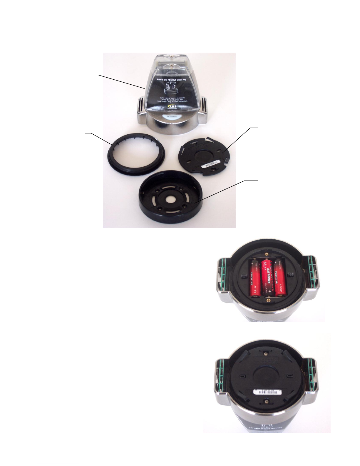
Page 12-2 T7501
KeyCall
Unit
Threadlock
Battery
Cover
Mounting
Plate
Typical KeyCall Setup
1. Unpack the KeyCall unit, contents include:
□ 1 KeyCall unit
□ 3 AA Batteries
□ 2 Pieces of Foam Tape
2. To assemble, place the 3 AA batteries into the
KeyCall.
3. Place the Thread-lock into the Housing with
the teeth facing down.
4. Place the Battery Cover over the Battery Compartment, screw in place with
the 2 #4-40 x 3/16‖ Screws.

T7501 Page 12-3
Assign KeyCall Units to Tables
Each KeyCall has an exclusive address that allows it to be associated with a
selected location. This section will require the user to have the Program key,
numbered KeyCall Order Keys, and the KeyCall units with batteries.
To assign:
1. Enter KeyCallTX program.
2. Select the Tables tab, type in Access Code 56789.
3. Press the Assign to Table button.
4. Position KeyCalls at least 6 feet from T7501.
5. Insert and remove the Program Key from the KeyCall unit. LED will blink
Red several times and then Green when it associates. On the screen, note
that a serial number entry is highlighted.
6. Assign as a Clearing Unit, Starter Unit, or Assign a table number to the
highlighted serial number.

Page 12-4 T7501
Turn counterclockwise to lock
Note: if a table number is assigned wrong or must be changed, highlight the
associated unit and Edit or Delete.
7. Repeat for all units to be assigned.
8. Press Assign to Table when finished.
Mounting the KeyCall
1. Place the Mounting Plate on the desired location using the 2 pieces of
double sided foam tape or using 4
screws.
2. Place the KeyCall unit onto the
Mounting Plate, press down, then turn
the unit counter-clockwise to lock (unit
should spin freely without pulling off the
Mounting Plate.)

T7501 Page 12-5
The KeyCallTX Program
Setup Window
The KeyCallTX software is set to activate on the start up of the PC. The program
will come up on the Orders window.

Page 12-6 T7501
Setup Window
1. From the Orders window, select the Setup tab. Note: An access code is
required.
2. At the Timing Interval section , set the timeouts
to alert servers and management that an order is overdue; the display for a
table will change colors and at last page a manager. These time limits vary
and can be set to the restaurant‘s requirements. Also set a default
message to notify when an order goes beyond the Page After time
interval.
3. At the System Configuration section set the required parameters for:
a. Restaurant ID- This is the System ID of the restaurant. ID is also
used for the Manager and Server Paging.
b. Manager Pager- Pager number of the Manager. This pager is
notified when an order is overdue. See section on Timing Interval.
c. Server Pager- Pager number of Server. This pager is notified when a
patron uses the Push for Service Button on the KeyCall. The Server
Pager number is separate from Manager Pager number.

T7501 Page 12-7
d. Low Battery Alert- Value set for the percentage left on the KeyCall‘s
batteries before an alert is seen. Recommended value is 15 for 15%.
e. Grid Columns- Preference on number of Grid Columns to appear on
the Orders window. Each Grid holds 12 orders. Choices up to 3
columns totaling 36 orders shown at one time. Note: User will need
to exit and re-enter program for this setting to take affect. On the
Orders widow, the user can also modify with the buttons
f. Clear Order- User much select to check the box to enable use of a
Clearing Unit (see description on page 12-14) or the Touch Screen
monitor (using the monitor on the PC) to Clear Orders from the
Orders window.
g. Beep Error- Enable Error beep on KeyCall unit and set Volume Level.
The Error Beep occurs when the KeyCall unit fails to connect to the
T7501 or a Key is inserted incorrectly.
h. Access Code- Password used to enter system. Change is NOT
recommended. Password must be a 1 to 5 digit number. NOTE: DO
NOT LEAVE ACCESS CODE FIELD BLANK.
i. CSV Destination- Specify a folder location where Reports data will be
stored as Comma Separated Value (CSV) data. Default location is
C:\KeyCallTX\Data.
j. Upgrade- Update the current Firmware version if connected to a
Network
k. Purge Data- Delete any stored reports.

Page 12-8 T7501
Order Window
Patrons are given numbered ―order keys” when they order. It is
recommended the server put the order key into the Starter Unit to begin a
timer (Elapsed time) of when the order is placed.
After the patron decides where to sit they insert the order key in the table
unit.
The table unit transmits the patron‘s location to the central monitor.
The Order key number, Table number, and Elapsed Time are shown on the
Order monitor.
The monitor for that table will change from white, to yellow, to orange, and
finally to red. Once red, the manager will be paged if the patron waits for
their order beyond a preset critical time.
After the patron is served, the server retrieves the key, and inserts the key
into a Clearing Unit to clear the order from the monitor.

T7501 Page 12-9
Order Information
To view basic details of an Order on the Orders Window, double-click the Order
and the Order Info window will pop-up.
o Order – Key number of customer.
o Table – Table number assigned to
the KeyCall unit.
o Elapsed – Elapsed Time.
Clear will clear the order. Note: If
Touch screen is not selected to clear a
unit under the Setup Window, a prompt
will ask for the access code to view the
Order Info.
To change the Table for an Order:
Double-click the Table number.
At the pop-up window, type in the new Table number
Press Enter
Close will exit the Order Info window.
Organizing the Orders Window
The window comprises of 12 rows per column, consisting of the Order, Table,
and Elapsed Time in each cell.
The number of columns can change from 1, 2, or 3 by pressing the buttons
The arrangement in each cell will not change.
Sorting
While active, the user can sort the orders according to Order, Table, or Elapsed
Time by pressing:
Table and Order will sort by ascending order, Elapsed Time by longest time.
Note: It is recommended to sort by the Order number.
.

Page 12-10 T7501
Navigating the Order Window
Page Up and Page Down to scroll through large numbers of orders.
Top will return to the top of the Order window.
Exit will exit the KeyCallTX program.
Customer Paging
To Page a customer (using LRS Guest Pagers):
Press the Customer button.
Enter the pager number and press Page button.
All customer pagers should range from number 201 and
above.
Manager or Server Paging
To Page a manager or server (using LRS
Alpha Staff Pagers):
Press the Manager or Server button.
Enter a message and press Page
button.
Note: The drop down box contains 3
preset messages and stores the last 7
messages typed by the user.

T7501 Page 12-11
Recall
The Recall button brings up a window showing the last 5 transactions. In the
event a transaction was Cleared, user can retrieve the information. Transaction
will resume from the initial start.
Key - Key number of Customer.
Table – Table number Key was used.
Delivered – Day and time order was
cleared.
Elapsed Time – Complete service time
to fulfill order.
To retrieve, highlight a transaction and press
the Recall button in the window.

Page 12-12 T7501
Status Window
The operating status of the KeyCall system can be periodically checked. The
T7501 tries to contact and check the battery status of each unit several times
daily.
A green display for a unit indicates acceptable performance.
If the Last Contact column is red it would indicate contact with a KeyCall unit
is lost and it should be checked.
A red indication in the Battery Level column indicates the batteries should be
replaced.

T7501 Page 12-13
Reports Window
Daily reports can be used to establish wait time trends.
Select the REPORTS tab.
Select the period of time to view.
Select the type of report to view
Daily Summary Report
Shows the average order delivery time
and number of covers for the period
selected
Daily Detail Report
Shows the detail order delivery time
for every order.
Report CSV
Saves the selected reports in CSV
(Comma Separated Values) to a
predetermined file (see setup).

Page 12-14 T7501
Using The KeyCall
Starter Unit
The Starter Unit is located near the starting point of a transaction. After an order
is placed, insert the Key into the Starter Unit, observe beginning of Elapsed Time
on the Orders window with order number.
Clearing Unit
The Clearing Unit is located near food pickup area. After a patron‘s order has
been delivered and Key retrieved, insert the Key into the Clearing Unit to confirm
completion of the transaction.
Service Button
Alerts the Server by sending a page that a Table requires assistance. This will
also cause the LEDs at the top of the KeyCall unit to flash.
There is a one-minute time limit between signals sent to the Server pager when
the button is pressed to reduce unnecessary requests.
Key Holder
Each KeyCall has four spaces (two on each side) to store Keys.
The KeyCall Keys
Programming Key
The Programming Key is used when assigning KeyCall‘s to the T7501.
Order Keys
The Numbered Keys are given to patrons after their order is placed. The number
is used in tracking the location of the customer when they sit down at a table.

T7501 Page 12-15
Troubleshooting
Re-Enter KeyCallTX Program
If the user ever exits the KeyCall program (without resetting the computer),
double-click the KeyCallTX icon.
Reassigning a KeyCall Unit in an Existing Install
1. Confirm 3 fresh AA batteries are in the unit.
2. On the KeyCallTX program, go to the Tables window, and press Assign to
Table.
3. Insert and remove any number key into the KeyCall unit.
4. Note that a special serial number entry is highlighted on the table
configuration window.
5. Accept the table number as is by press Enter, otherwise Edit or Delete.
6. Repeat for all units to be reassigned.
7. Press Assign to Table to end.
Low Battery Indicator – Order Window
If the LO BAT message appears on the Orders Window, a KeyCall unit has
reached the low battery limit established in the Setup Window.
It is recommended to replace the batteries in the KeyCall unit.

Page 12-16 T7501
No Connection – Order Window
If the NO CONNECTION message appears on the Orders Window:
Check the crossover cable to the T7501.
No T7500 Connection – Order Window
If NO T7500 message appears on the Orders Window:
Check that the T7501 is powered on.
Check the crossover cable to the T7501.
Enter the Setup Window, go to the Network section, see if Network states NO
CONNECT and that the T7501 IP address is highlighted in red, select
Connect
Check TCP/IP settings of PC and T7501:
1. On T7501,check going into Setup, enter access code 5-6-7-8-9.
2. Select System, Network, LAN Config.
3. On PC, select Start, Control Panel, Network Connections.

T7501 Page 12-17
Computer
TX-7501
IP (inet addr)
192.168.200.25
192.168.200.155
Netmask (Mask)
255.255.255.0
255.255.255.0
Gateway
(Bcast)
192.168.200.254
192.168.200.1
Primary DNS
192.168.200.1
4. Select the Network Connection.
5. Select Properties.
6. Highlight the Internet Protocol (TCP/IP), and then select Properties.
Settings should appear as:
Notes: DNS Server is not required on the PC.
The Secondary DNS is not required on the T7501.
7. If Computer settings do not match the table, correct.
8. If T7501 does not match, call LRS.


T7501 Page 13-1
UP
SCROLL BUTTON
DOWN
SELECT/READ
BUTTON
Read All
10/25 1038am
UP
SCROLL
DN
CHAPTER 13 USING THE STAFF PAGERS
Staff Pagers Available for the T7501:
RX-E467 4-Line Alpha Numeric Pager
SP4 Star Pager
SP5 1-Line Rechargeable Alpha Numeric Pager
Messaging
The 4-Line Alpha Pager and Star Staff Pager are used as the Staff or Manager
pager. Paging with the T7501 requires using the Staff or M1 – M4 keys on the
Main Keyboard or using the Staff, Server, or Manager virtual buttons viewed on
the computer monitor during various applications.
Using the RX-E 4-Line Alpha Numeric Pager
Menus
Selecting functions
1 To select, Press Scroll Dn (or Up) until desired item shows.
2 Press Scroll to select
3 Press Read/Select to start/finish.
Power On/Off
Set ON (if unit is off)
1. Press and hold Scroll Up until YES NO shows.
2. At Power ON? Select YES.
3. Press Read/Select button.

Page 13-2 T7501
[01/16] 01/02/2006
10:04 am
This is the message that you
received this time
Set OFF
1. Select Power OFF?
2. Select YES/NO
3. Press Read.Select one time
Read Message
New At receipt the message is displayed.
Press Read/Select to display.
Stored To review stored messages,
1 Select Read All?
2 Press Read/Select to display messages and time stamps.
Delete Messages
1 Select Delete All?
2 Press Scroll to select YES/NO
3 Press Read/Select button.
Time/Date Set
1 Select Set Time/Date.
2 Press Read/Select
3 Press Scroll to set each time or date segment and press Read/Select to move
through the segments.
Set Contrast
1 Select Set Contrast.
2 Press Read/Select.
3 Scroll DN/UP to adjust.
Auto ON/OFF
1 Select Auto On/Off.
2 Press Read/Select.
3 Select ON/OFF.
4 Press Read/Select and Scroll to set on off time segment.

T7501 Page 13-3
Set Keytone On/Off
1 Select Set Keytone.
2 Press Read/Select.
3 Select On or Off
4 Press Read/Select to set.
Select Alert
1 Select Set Alert Mode.
2 Select Beep
Select Loud or Soft
Select Duration
3 Select Vibe or Off.
Select Strong or Weak
Select Pulse Type
Select Duration
Battery
The RX-E 4-Line Alpha pager uses 1 AAA Battery.
Programming
To program the pager, see Chapter 6 Battery Operating Alphanumeric Pagers.

Page 13-4 T7501
Using the Star Pager
Charging
Any rechargeable pager will require use of an LRS charger. The Star Pager
(SP4) uses the Charger 9 (CH-R9.)
1. Place the pager in the charger
2. Allow unit to charge fully overnight.
3. Remove from charger, and pager will vibrate, beep, and light all lights as a
verification that it is working
4. Replace the pager in the charger at the end of each day.
Programming
To program the Staff Star Pager, see Chapter 6 Rechargeable (Star) Staff
Pagers.
Note:
A Guest version of the Star Pager is available and must be purchased separately
from a Staff version. To page a Star Guest Pager with the T7501, press the Page
key on the 4 button keyboard or use the Guest virtual buttons viewed on the
computer monitor during various applications
To program the Guest Star Pager uses the same instructions, at Step 7, select
Guest in place of Staff.

T7501 Page 13-5
SELECT
BUTTON
Using the SP5 1-Line Rechargeable Alpha Numeric Pager
Charging
The SP5 uses the Charger 5 (CH-R5.)
1. Place the pager in the charger.
2. Allow unit to charge fully overnight.
3. Remove from charger, pager will vibrate or beep to show it is working.
4. LCD will show the pager‘s ID
5. Replace the pager in the charger at the end of each day.
Menus
To access the vibe/contrast menu, remove the pager from the charger. While
vibrating or beeping, press and hold the Select button for 8 seconds. This top
level menu will display:
If you PRESS and RELEASE the SP5 pager button the menu will change to:
To exit this menu wait 8 seconds.
To re-enter the vibe/contrast menu at any time, reset the pager, and then hold
the SP5 pager button.
Vibe
To set the Vibration Level
1. Enter the vibe/contrast menu as described above
2. highlight the Vibe selection then PRESS and HOLD the SP5 pager Button
until the screen shows

Page 13-6 T7501
3. Press or hold the Select Button to the desired vibration level. The level will
rise to max, Release the Select Button and press or hold again until the level
goes to minimum or desired level
4. To exit, wait 8 seconds. And the pager will go back to the vibe/contrast menu.
Contrast
To set the Contrast Level
1. Enter the vibe/contrast menu as described above
2. highlight the Contrast selection then PRESS and HOLD the SP5 pager Button
until the screen shows
3. Press or hold the Select Button to the desired Contrast. The level will
increase to max (NOTE: screen could be dark and hard to read), Release the
Select Button and press or hold again to change the level back towards the
minimum or to desired contrast.
4. To exit, wait 8 seconds. And the pager will go back to the vibe/contrast menu.
5. To exit this menu wait 8 additional seconds.
Settings
To view the current pager settings
1. Remove pager from the charger.
2. Press the Select Button repeatedly to scroll through the settings:
C1: [Restaurant ID number] and Pager ID number
C2: [Restaurant ID number] and All Page number
C3: [Restaurant ID number] and System ID number
G: Group number
Enc: Encryption enabled (128) or none
Ver: Current Firmware Version
3. To exit, wait 8 seconds.

T7501 Page 13-7
Messages
The pager stores the last 5 received messages. To view the messages:
1. Press the Select Button once.
2. Messages 2 lines in length will show an > symbol on the end of the first line
and an < on the second line. Messages over 2 lines in length, the middle
lines will show ―< the next line of the message >‖
3. Press the Select Button to continue scrolling forward through the message or
messages
Time
Pager will display the current time. This feature is automatically updated by the
T7501 transmitter. If the time does not appear, a flashing star will appear on the
right side of LCD to show pager is operational.
Programming
To program the pager, see Chapter 6 Battery Operating Alphanumeric Pagers.


T7501 Page 14-1
CHAPTER 14 GUEST PAGERS
Guest Pagers Available for use with the T7501:
AdverTeaser
Coaster Calls
Lobster Calls
Pizza
Messaging
To page Guest Pagers with the T7501, press the Page key on the 4 button
keyboard or use the Guest virtual buttons viewed on the computer monitor during
various applications.
When the Guest is paged, the pagers will light and/or vibrate to indicate their
table is ready.
Programming
To program the Guest Pagers, refer to Chapter 6 Program Pagers Pizzas,
Lobsters, and Adverteaser Guest Pagers.
Charging
Any rechargeable pager will require use of an LRS charger.
1. Place the pager in the charger. For Coasters, Pizza, and Lobster pagers, do
not stack more than 10 pagers at a time on a Charger.
2. Allow unit to charge fully overnight.
3. Remove from charger, and pager will vibrate, beep, and light all lights as a
verification that it is working
4. Replace the pager in the charger at the end of each day.
The pagers all use different chargers:
□ Coasters use the Charger 8 (CH-R8)
□ Adverteasers and Star Pagers use the Charger 9 (CH-R9)
□ Lobster Pagers use the Lobster Charger (CH-LP)
□ Pizza Pagers use the Pizza Charger (CH-PZ)

Page 14-2 T7501
AdverTeaser
Coaster Call
Lobster Call
Pizza Pager
 Loading...