

Page 1
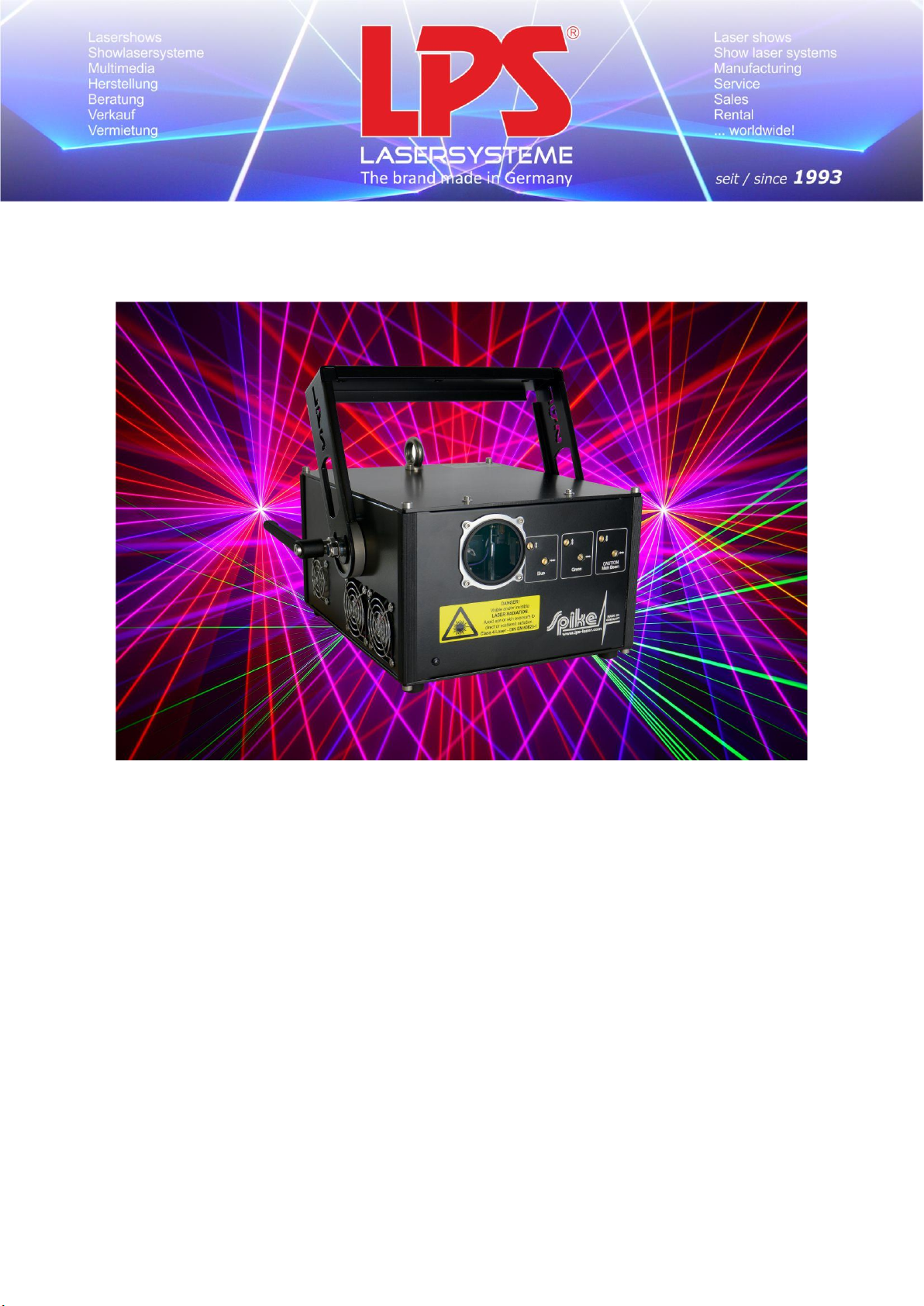
Manual
As of February 2019
P a g e 1 | 11
LPS-Lasersysteme Siegmund Ruff / CEO Haidschwaerze 18 72131 Ofterdingen Germany
Page 2
Foreword
CAUTION!
Should an error occur due to improper handling or maintenance, there is no warranty.
Thank you for purchasing an LPS product.
Before you operate this product the first time, please read this manual carefully.
Our systems are equipped with high sensitive electronics and mechanics.
Strong shocks can cause significant damage to the system.
Contents
Foreword ......................................................................................................................................................... 2
Contents .......................................................................................................................................................... 2
1. Commissioning .................................................................................................................................... 3
1.1 Areas of use ........................................................................................................................................ 3
1.2 Electrical Connection .......................................................................................................................... 3
1.3 Installation .......................................................................................................................................... 3
1.4 Operation ............................................................................................................................................ 3
1.5 Unpack and connect ........................................................................................................................... 4
2. Technical Specification ....................................................................................................................... 5
3. Overview ............................................................................................................................................. 7
3.1 Housing front view .............................................................................................................................. 7
3.2 Housing back view .............................................................................................................................. 8
3.3 Power switch ...................................................................................................................................... 9
3.4 Key switch ........................................................................................................................................... 9
3.5 Emergency Off .................................................................................................................................... 9
3.5.1 Emergency in ...................................................................................................................................... 9
3.5.2 Emergency through ............................................................................................................................ 9
3.6 ILDA In / Through .............................................................................................................................. 10
3.7 Emission LED ..................................................................................................................................... 10
4. Maintenance ..................................................................................................................................... 10
5. Beam Adjustment ............................................................................................................................. 11
LPS-Lasersysteme Siegmund Ruff / CEO Haidschwaerze 18 72131 Ofterdingen Germany
P a g e 2 | 11
Page 3

1. Commissioning
1.1 Areas of use
This product must be used for laser shows only.
This device is designed for mobile use and for permanent installations.
1.2 Electrical Connection
This product is approved to be operated only with an alternate current of 100 - 240 V.
1.3 Installation
It is required to mount the device only on a fixed truss or base.
In order to guarantee sufficient ventilation, leave 50 cm free space minimum around the device.
1.4 Operation
Operate the device only when familiar with its functions. Do not permit operation by persons not
qualified for operating the device. Most damages are the result of unprofessional operation!
Please consider that unauthorized modifications on the device are forbidden due to safety reasons!
If the device is operated in any way different to the one described in this manual, the product may
suffer damages and the guarantee becomes void.
P a g e 3 | 11
LPS-Lasersysteme Siegmund Ruff / CEO Haidschwaerze 18 72131 Ofterdingen Germany
Page 4

1.5 Unpack and connect
Please note:
LPS-Lasersysteme cannot be made liable for damages caused by incorrect installations and
unskilled operation!
Check the content of the package of its completeness.
The following parts are included:
- Laser system
- Manual
- Power plug (1 piece)
- Two keys for the key-interlock
- E-Stop, key for E-Stop, 10m cable
Connect the D/A converter and laser system with the data cable.
Plug in the power supply of the laser system and the D/A converter (power plug).
Make sure that the show laser system is mounted stable and cannot fall down.
Certifications:
IEC 60825-1
DIN EN 60825-1
E DIN 56912
CAUTION!
If you use controls or adjustments or if you perform procedures other than those specified here,
this might result in hazardous radiation exposure!
The laser exposure of this Lasersystem is able to ignite flammable materials.
Improper use of the Lasersystem might harm people.
There is a high risk of eye injuries if the laser power is not well calculated at any audience scanning.
LPS-Lasersysteme Siegmund Ruff / CEO Haidschwaerze 18 72131 Ofterdingen Germany
P a g e 4 | 11
Page 5
2. Technical Specification
Laser source
Laser diodes (Pure Diode)
Operating voltage
100 V – 240 VAC
Voltage line frequency
50 Hz / 60 Hz
Operating current
From 0.9 A
Power consumption
Approx. 260 W
Cooling requirements
air-cooled, optimized airflow
Degree of protection
IP 42
Protection class
1, protection ground
Operating temperature
5° - 40° C
Warm-up time
none
Total laser power
Spike 4K Green
3.8W Green
Spike 4K RGB
3.6W RGB
Spike 7K RGB
6.8W
Modulation
analogue modulation up to 50 kHz
LPS-Lasersysteme Siegmund Ruff / CEO Haidschwaerze 18 72131 Ofterdingen Germany
P a g e 5 | 11
Page 6
Wavelength
Spike 4K Green
3.8W green@520nm
Spike 4K RGB
3.6W RGB
800mW red@638nm, 1W green@520nm, 1.8W blue@445nm
Spike 7K RGB
6.8W RGB
1.2W red@638nm, 2W green@520nm, 3.6W blue@445nm
Scanner
Spike 4K Green
30kpps Scanner
Spike 4K RGB
30kpps Scanner
Spike 7K RGB
30kpps Scanner
Scanner UPGRADE
52kpps@7° with digital driver, max 60° angle
FB4 UPGRADE
FB4 Max upgrade
Deflection angle
maximal 50°, at other scanners larger deflection angles are
possible.
Dimension and weight
from 220 x 300 x 150 mm
7 kg
LPS-Lasersysteme Siegmund Ruff / CEO Haidschwaerze 18 72131 Ofterdingen Germany
P a g e 6 | 11
Page 7
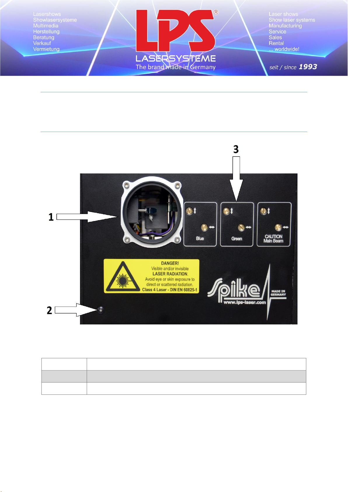
3. Overview
1
Laser output window
2
LED laser emission
3
Alignment aperture
The overview will help you to find a better handle to the functions of the systems.
3.1 Housing front view
P a g e 7 | 11
LPS-Lasersysteme Siegmund Ruff / CEO Haidschwaerze 18 72131 Ofterdingen Germany
Page 8
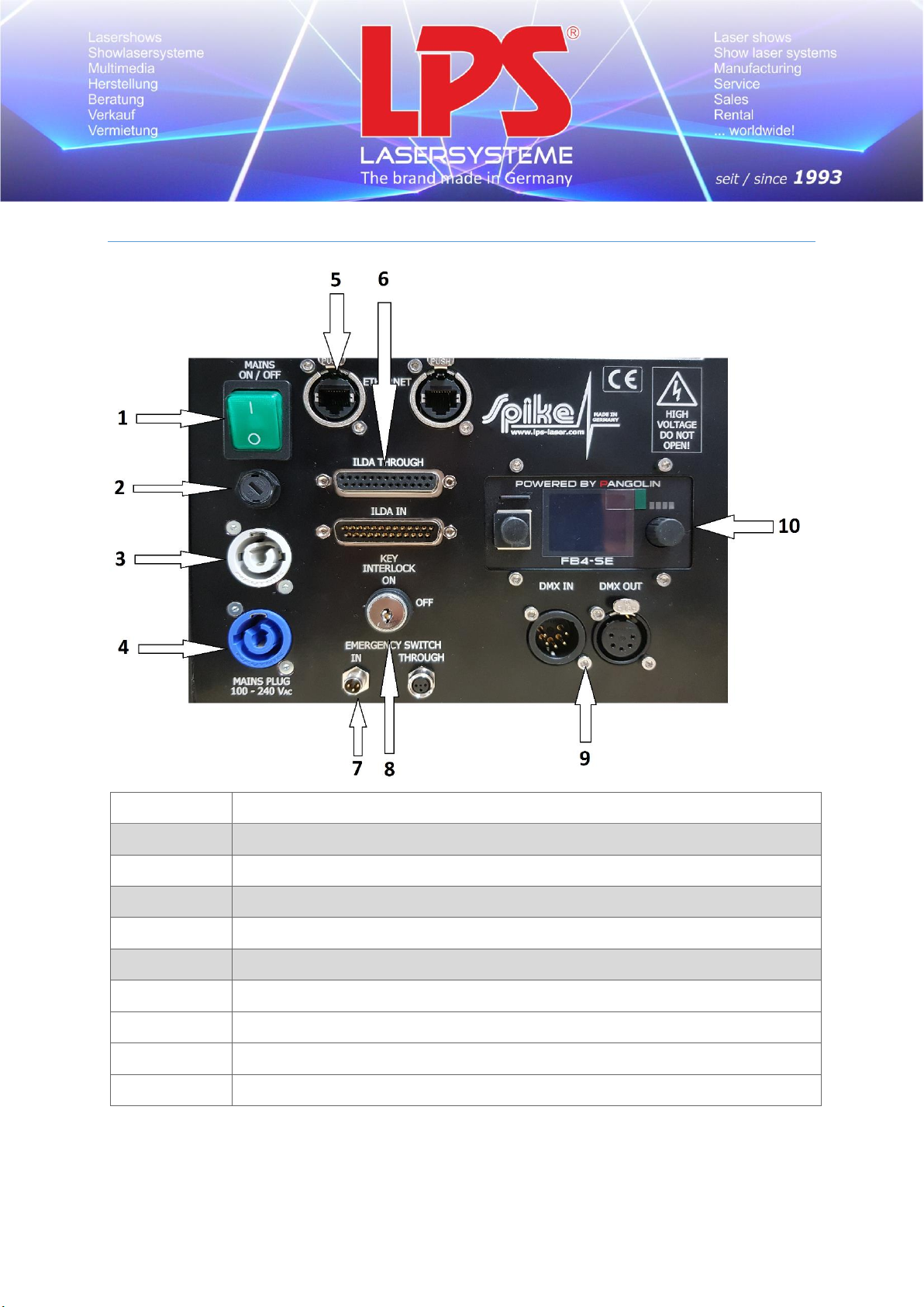
3.2 Housing back view
1
Power switch illuminated
2
fuse
3
Powercon out
4
Mains Plug (Powercon In)
5
Ethernet IN/OUT
6
ILDA IN / THROUGH
7
Emergency IN / THROUGH
8
Key-interlock „Laser Off / On“
9
DMX IN / OUT
10
Pangolin FB4 (Laser settings)
P a g e 8 | 11
LPS-Lasersysteme Siegmund Ruff / CEO Haidschwaerze 18 72131 Ofterdingen Germany
Page 9

3.3 Power switch
Use the power switch to turn the laser system on and off.
When the laser system is turned on, the power switch glows.
3.4 Key switch
Use the key switch to activate or deactivate the laser system. Only the lasers will be switched on and
off in this process. All other components, which are integrated in the laser system, will still work.
3.5 Emergency Off
3.5.1 Emergency in
Connect the emergency-off switch to the 3 pole socket (male).
Pin Assignment:
Pin No. Name Note
Pin 1 VCC out 4.3 V output voltage
Pin 4 GND GND
Pin 3 Return connected voltage (return line)
3.5.2 Emergency through
Connect the next laser system at this 3 pole socket (female). You only need one
emergency-off switch to switch off several laser systems at the same time.
Pin Assignment:
Pin No. Name Note
Pin 1 VCC out 4.3 V output voltage
Pin 4 GND GND
Pin 3 Return connected voltage (reduction)
P a g e 9 | 11
LPS-Lasersysteme Siegmund Ruff / CEO Haidschwaerze 18 72131 Ofterdingen Germany
Page 10

3.6 ILDA In / Through
This socket is an ILDA compatible D-sub socket. Therefore, any ILDA-compatible laser software can be
used for this laser system.
Connect your controller with the ILDA In by an ILDA-cable.
If you want to use the same signal on another laser system, use the ILDA Through socket for that.
To get the best results of signal transmission, only shielded and twisted-pair cables should be used.
3.7 Emission LED
Laser emission LED
This LED is lighting up yellow if all safety checks are in good conditions. It displays that the laser
output is possible now.
If this LED is not lighting up, one of the interlocks has deactivated the laser modules.
Please check if all interlocks are enabled correctly.
4. Maintenance
Dust, fog fluid, etc. cause deposits on mirrors, which might evoke a substantial decrease in laser
power.
Therefore a professional and periodic cleaning is essential!
LPS-Lasersysteme recommends a regular service, which should be implemented at least
once a year.
Benefits:
- A complete professional check of the system by an expert can prevent minimum technical
errors and / or attrition with large consequences.
- Due to inadequate cleaning of the fan and the heatsink, overheating and electronic defects
may occur.
- By its completely closed optical area, a pollution is hardly possible, but still not excluded.
Therefore, it should be checked during the regular cleaning of the electronics sector,
whether and how dirty the optical area is.
- For cleaning the electronic area, please remove the front and the back plate of the laser
system and remove all dust particles.
- For cleaning the optical and the laser area, please remove the top and the front of the laser
system.
- For cleaning, only manufacturer's recommended products should be used, because wrong
cleaning supplies can damage the components and warranty voids.
P a g e 10 | 11
LPS-Lasersysteme Siegmund Ruff / CEO Haidschwaerze 18 72131 Ofterdingen Germany
Page 11
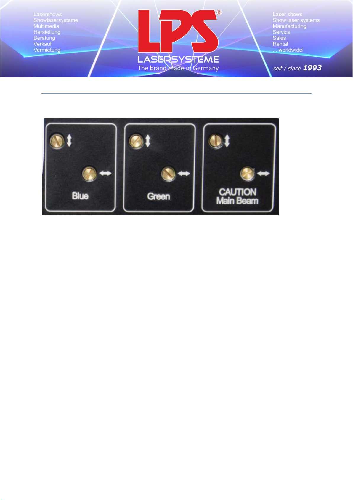
5. Beam Adjustment
For the adjustment of the single colours there is a mechanic on the front of your laser system:
Adjusting the colours:
1. Move the green beam by turning the screws, until it is aligned on the red beam at the projection
zone.
Hint: Dim the blue laser module to zero for that.
2. Move the blue beam by turning the brass-screws, until it is aligned on the red beam at the
projection zone.
Hint: Dim the green laser module to zero while you are moving the blue beam.
Now your colours should be aligned on each other.
Main Beam:
The position of the Main Beam (red) is only to be changed, if the beam is not aligned on the scanner unit
correctly!
P a g e 11 | 11
LPS-Lasersysteme Siegmund Ruff / CEO Haidschwaerze 18 72131 Ofterdingen Germany
 Loading...