

Page 1
Manual
As of February 2019
P a g e 1 | 9
LPS-Lasersysteme Siegmund Ruff / CEO Haidschwaerze 18 72131 Ofterdingen Germany
Page 2

Foreword
CAUTION!
Should an error occur due to improper handling or maintenance, there is no warranty.
Thank you for purchasing an LPS product.
Before you operate this product the first time, please read this manual carefully.
Our systems are equipped with high sensitive electronics and mechanics.
Strong shocks can cause significant damage to the system.
Contents
Foreword ................................................................................................................................................. 2
Contents .................................................................................................................................................. 2
1. Commissioning ............................................................................................................................ 3
1.1 Areas of use ................................................................................................................................. 3
1.2 Electric connection ...................................................................................................................... 3
1.3 Installation ................................................................................................................................... 3
1.3.1 Mount on an LPS-Bax system ...................................................................................................... 4
1.3.2 Mount on an Spike system .......................................................................................................... 5
1.4 Unpack and connect .................................................................................................................... 6
2. Technical specification ................................................................................................................ 6
3. Overview...................................................................................................................................... 7
3.1 Housing front view ...................................................................................................................... 7
3.2 Housing side view ........................................................................................................................ 8
4. DMX-512 connection ................................................................................................................... 9
4.1 DMX protocol .............................................................................................................................. 9
LPS-Lasersysteme Siegmund Ruff / CEO Haidschwaerze 18 72131 Ofterdingen Germany
P a g e 2 | 9
Page 3
1. Commissioning
Attention:
If you try to mount the SpectraL³ on an LPS-BaX laser system,
while the laser system is hanging, the laser system may fall apart!
1.1 Areas of use
This device is designed for mobile use and for permanent installations.
1.2 Electric connection
This product is approved to be operated only with 9V – 12V DC
1.3 Installation
Your SpectraL³ device was delivered with mounting brackets that fit only the laser system you
ordered (either an LPS-BaX or a Spike laser system).
Mounting the device on an LPS-Bax System, may only be done while the laser system stands safe.
As you need to release carrying connections of the laser system, while mounting the SpectraL³
device.
P a g e 3 | 9
LPS-Lasersysteme Siegmund Ruff / CEO Haidschwaerze 18 72131 Ofterdingen Germany
Page 4
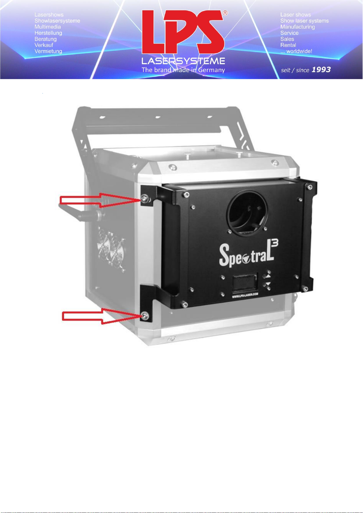
1.3.1 Mount on an LPS-Bax system
To mount the device on an LPS-BaX laser system, you need to open the four screws (two screws on
the left and two screws on the right).
Use the same four screws to fix the SpectraL³ device on the laser system, as shown in the picture
above.
P a g e 4 | 9
LPS-Lasersysteme Siegmund Ruff / CEO Haidschwaerze 18 72131 Ofterdingen Germany
Page 5
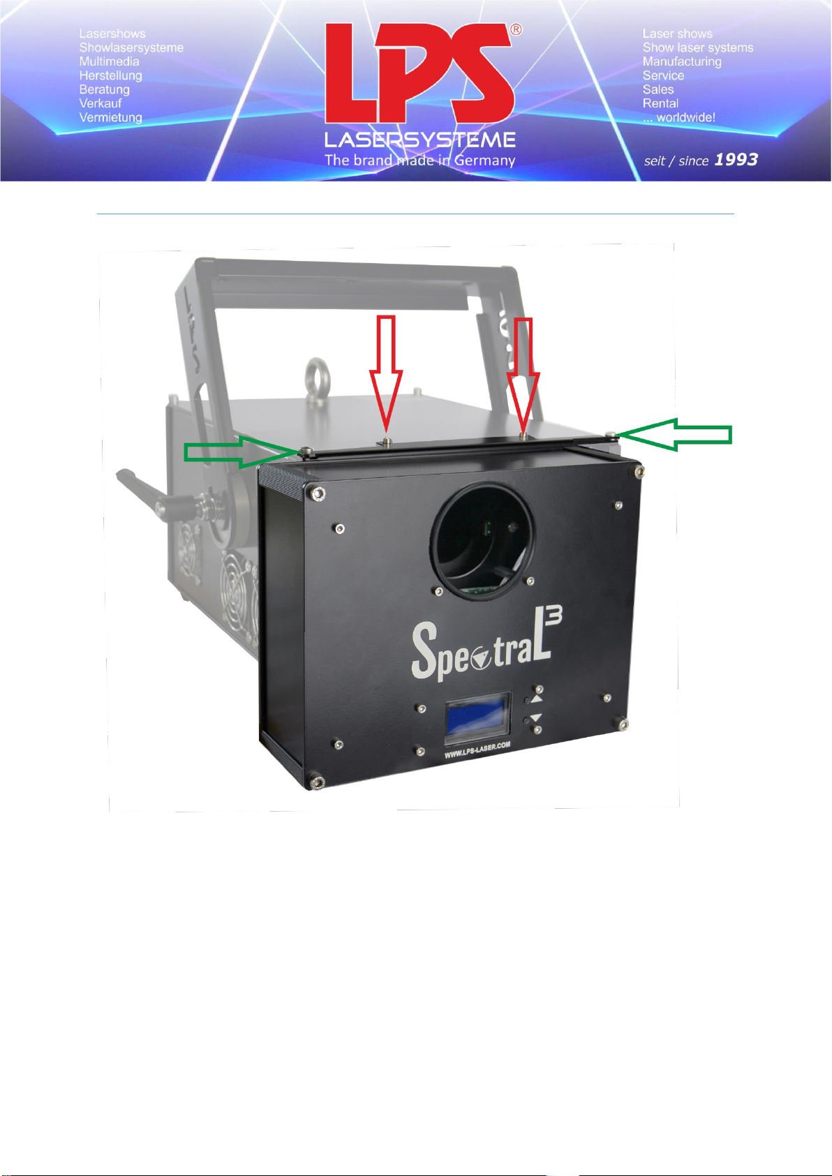
1.3.2 Mount on a Spike system
To mount the SpectraL³ device on a Spike laser system, you need to open the four screws which are
marked with the red arrows (two screws on the top and two screws on the bottom).
You do not need to open the screws which are marked with the green arrows.
Use the same four screws to fix the SpectraL³ device on the laser system, as shown in the picture
above.
P a g e 5 | 9
LPS-Lasersysteme Siegmund Ruff / CEO Haidschwaerze 18 72131 Ofterdingen Germany
Page 6
1.4 Unpack and connect
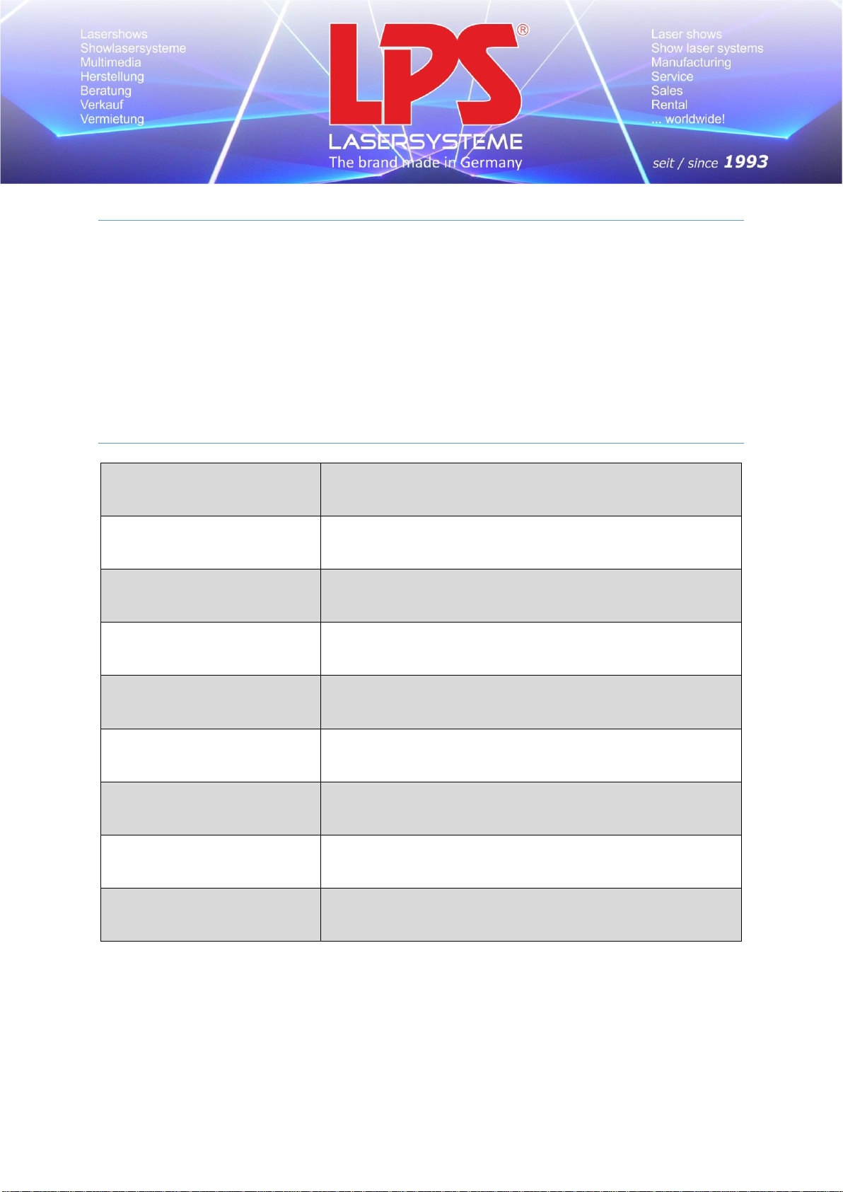
Operating voltage
12 VDC
Operating current
< 1100 mA
Power consumption
< 13 W
Degree of protection
IP 42
Protection class
3, extra low voltage
Operating temperature
5° - 40° C
Warm-up time
none
Deflection angle
> 45° (wide effect angle)
Dimension and weight
220 x 170 x 78 mm
1,8 kg
Check the content of the package of its completeness.
The following parts are included:
- SpectraL³ device
- 12V AC / DC power supply
- Mounting brackets for either LPS-BaX or Spike laser systems.
- Connect the SpectraL³ device with your DMX console.
- Plug in the 12V AC/DC power supply and connect it with your device.
2. Technical specification
LPS-Lasersysteme Siegmund Ruff / CEO Haidschwaerze 18 72131 Ofterdingen Germany
P a g e 6 | 9
Page 7
3. Overview
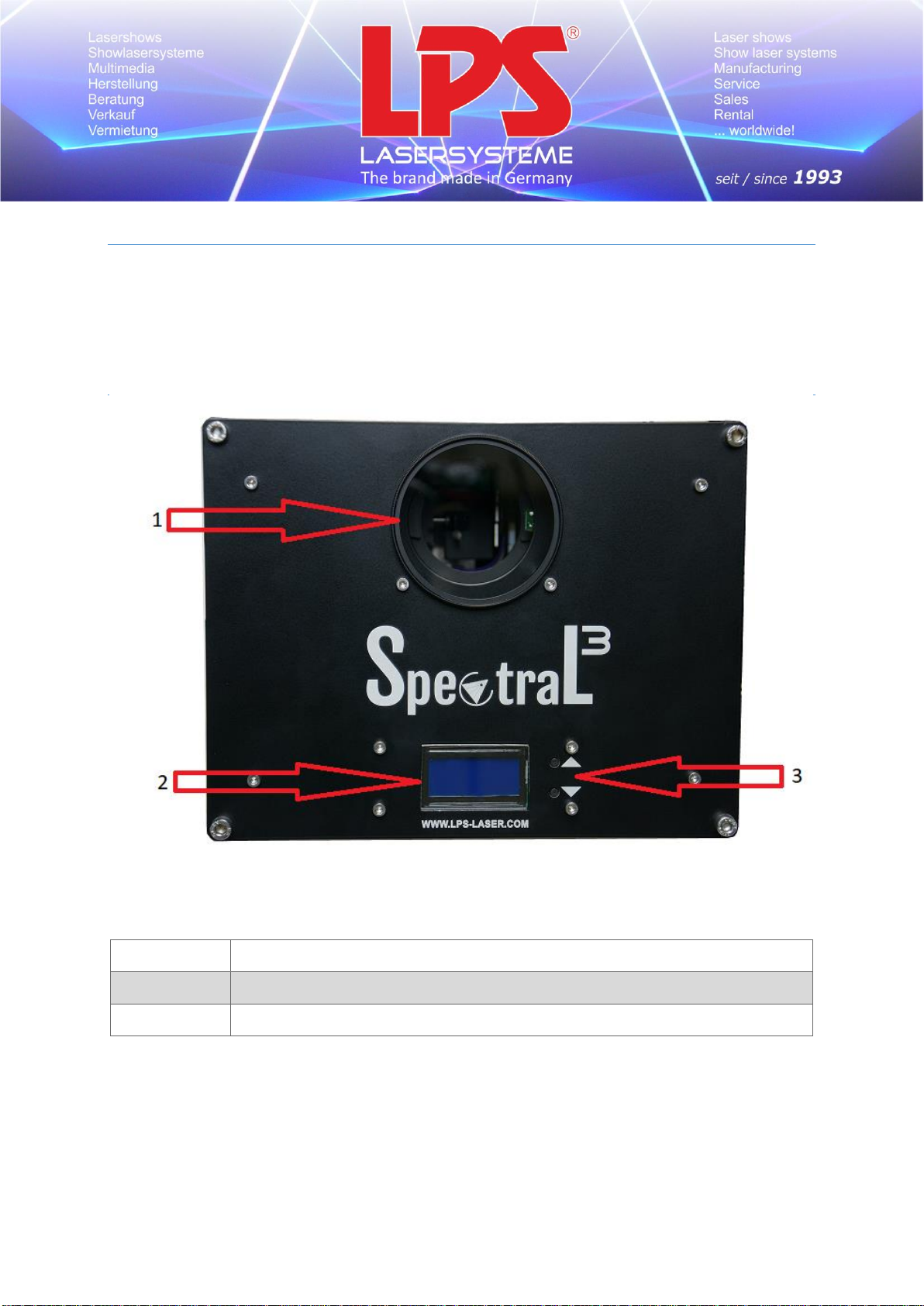
1
Laser output window
2
Display
3
Control buttons for setting the DMX address
The overview will help you to find a better handle to the functions of the systems.
3.1 Housing front view
LPS-Lasersysteme Siegmund Ruff / CEO Haidschwaerze 18 72131 Ofterdingen Germany
P a g e 7 | 9
Page 8
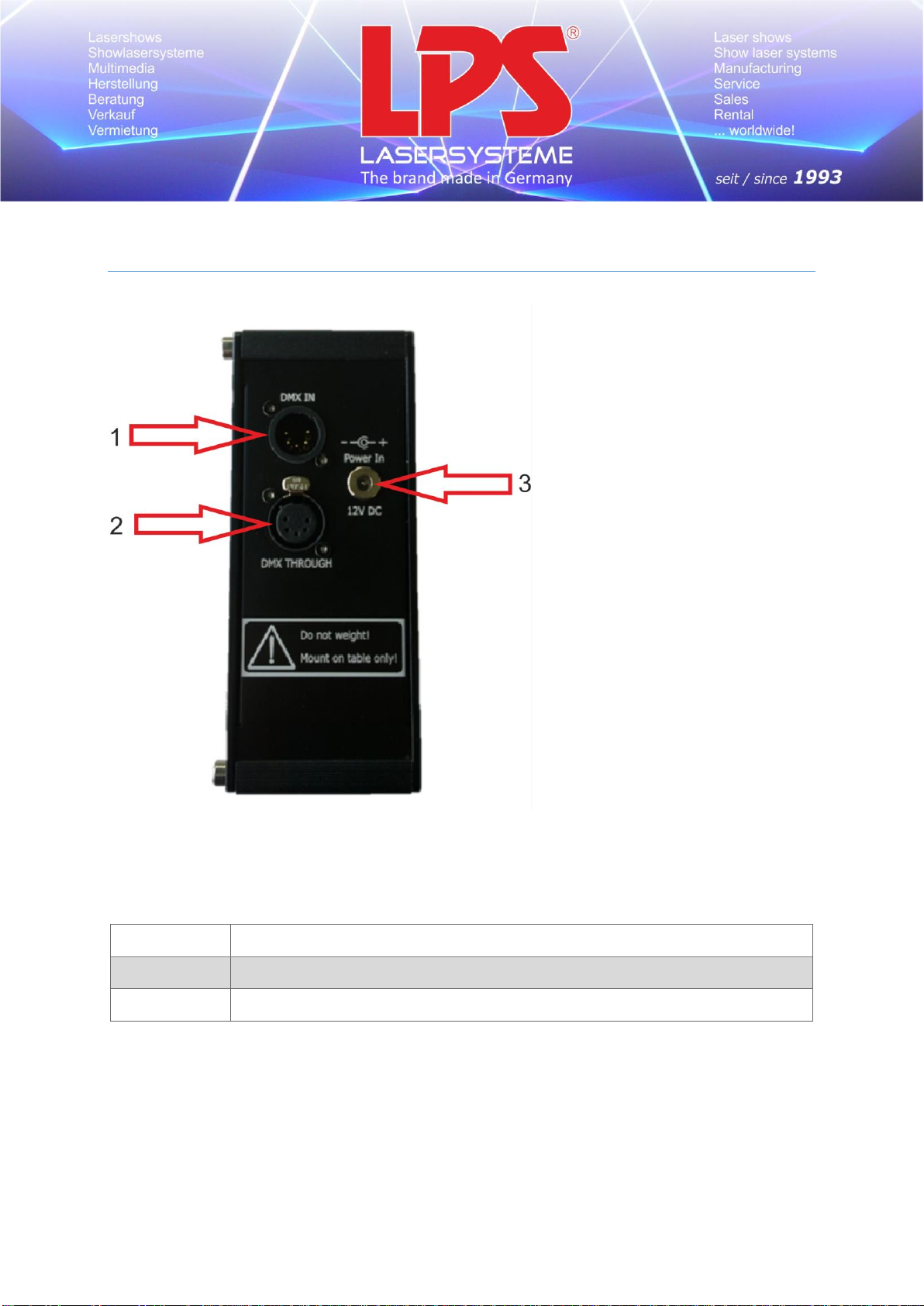
1
5-pin DMX In
2
5-pin DMX out
3
Power In (9V – 12V DC)
3.2 Housing side view
LPS-Lasersysteme Siegmund Ruff / CEO Haidschwaerze 18 72131 Ofterdingen Germany
P a g e 8 | 9
Page 9
4. DMX-512 connection
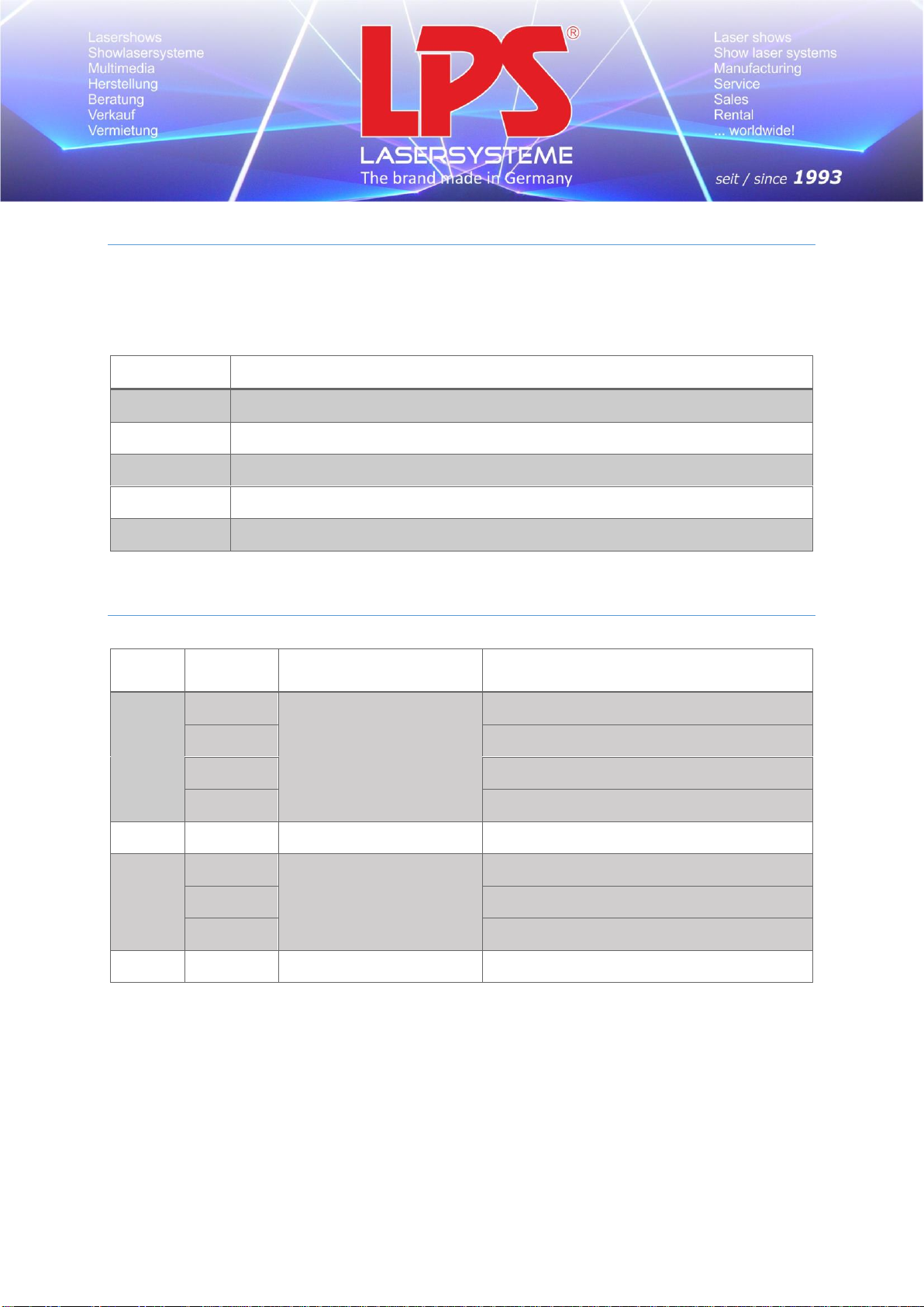
Pin
Description
1
Shield
2
Signal (-)
3
Signal (+)
4
Not connected
5
Not connected
Channel
DMX
Value
Function
Type of control
1
0 .. 57
Gobo selection
Open (no effect)
58 .. 127
Lumia
128 .. 198
Spectral line
199 .. 255
Spectral grating
2
0 .. 255
Gobo rotation manually
Setting to absolute angle
3
0 .. 116
Gobo rotation
automatically
Clockwise, getting slower
117 .. 138
No rotation
139 .. 255
Counterclockwise, getting faster
4
255
Reset
Reset the position: 0 -> 255 -> 0
The fixture is equipped with 5-pin XLR sockets for DMX input and output. The sockets are wired in
parallel. Only use a shielded twisted-pair cable designed for RS-485 and 5-pin XLR-plugs and
connectors, in order to connect the controller with the fixture, or one fixture with another.
4.1 DMX protocol
LPS-Lasersysteme Siegmund Ruff / CEO Haidschwaerze 18 72131 Ofterdingen Germany
P a g e 9 | 9
 Loading...