

Page 1
LPKF ProtoMat S
Manual
Order Code: 1000447
Page 2

Page 3

ProtoMat S
Manual
Version 0.9
English
LPKF Laser & Electronics AG
Osteriede 7
D-30827 Garbsen
Germany
Phone +49-5131-7095-0
Fax +49-5131-7095-90
Email [email protected]
Page 4

ProtoMat S
2 © 2011 LPKF AG
Publisher LPKF Laser & Electronics AG
Osteriede 7
D-30827 Garbsen
Germany
Phone: +49-5131-7095-0
Fax: +49-5131-7095-90
Email: [email protected]
Order code 10000447
File name ProtoMat_S_HB_V0.9_ENG.docx
Version 0.9
Creation date 28.03.2011
Print date 28.03.2011
Copyright © 2011 LPKF AG
This document and its contents in whole and in part are subject
to copyright. The reproduction, translation or duplication of the
contents as photocopy or any digital form requires written
permission of LPKF AG.
Product and
brand names
Product and brand names are trademarks of LPKF Laser &
Electronics AG, registered among others at the US Patent and
Trademark Office: LPKF
®
and the company logo, # 2,385,062
and # 2,374,780; Solarquipment
®
, # 3,494,986; ProConduct®, #
3,219,251; Allegro®, # 3,514,950.
Page 5

ProtoMat S
© 2011 LPKF AG 3
General information
General information
Introduction
All information about assembling, start up,
operating and maintenance, respectively
troubleshooting of the delivered machine are
provided by this product manual. This manual
is written for persons with a basic knowledge
of installing and operating software controlled
machines. General knowledge about safety at
work as well as basic knowledge about PC
handling, based on Microsoft Windows®
operating system, is required.
Availability
This document must be available in complete
and legible condition at the workplace near
the machine. Any person, allowed to operate
the machine, must read and understand this
manual. The machine owner has the duty to
ensure that all safety instructions, described in
the manual, will be heeded by the operators.
Notation
To facilitate the reading and understanding of
the document information text attributes, text
notations and text structures are used. The
text attributes (highlighting) inside this
document are defined as follows:
Attribute Function
Bold Important information
Italic Brand name
Bold + Italic LPKF Brand name
[…] Button
\...\ Input or output field
<…> Check box
{…} Radio button
>…>…> Menu path
/…/ Pointer to a numeric character
inside an image
Images
All pictures or graphics of this document are
framed. Every figure is characterized with a
continuously numbered title, for example “Fig.
1: Overview“. Numeric character inside the
image is used for the identification of specified
components or operation steps. Sideward
showing arrows inside the image are used to
indicate an activity direction.
Tables
Any technical data, facts or special context
will be organized in tables. Every table is
characterized with a continuously numbered
title, for example “Tab. 1: Scope of delivery“.
The table will be created with a highlighted
headline and labelled columns.
Page 6
ProtoMat S
4 © 2011 LPKF AG
Genral information
Procedure descriptions
For this manual step by step procedures or
workflows are compiled to operation sequences. An individual operation sequence
consists of at least three components
Title+Step+ Result.
Component Description
■ Title
Short description of the
expected result – characterized with a prefixed “■“.
1. Step A consecutively numbered
order of the individual work
item of the described
procedure.
➨ Partial
result
Partial result of an operation
step. The operation sequence
is continuously progressed.
♦ Result
Result of the operation
sequence - characterized with
a prefixed “♦“.
Symbols and signal words
Inside this document the following symbols
will be used to indicate important information:
Symbol Description
Safety instruction
WARNING – dangerous hazard
to people
ATTENTION – a machine
damage is possible
Note
The note will be used for any
information about the optimal
solution for a realisation of a
specific function or operation.
Note
The memo will be used for any
additional information about a
function or operation step.
© Copyright
® Registered Trademark
Registered trademark
The LPKF logo and the LPKF product names
are registered trademarks of LPKF Laser &
Electronics AG.
Microsoft and Windows are brand names or
registered trademarks of the Microsoft Corporation in USA and/or international.
All other brand names belong to the respective owner.
Standards
The following standards and guidelines had
been pursued for the creation of this
document:
Standard Description
DIN 5008
05-2005
Rules for writing and layouting
VDI 4500
Bl.1,2
11-2006
Technical documentation Definitions and legal basics
IEC 62079
11-2001
Preparation of instructions Structuring, content and
presentation
ISO 12100-2
02-2003
Safety of machinery - Basic
concepts, general principles for
design - Part 2: Technical
principles
DIN EN
60204
01-2006
Safety of machinery - Electrical
equipment of machines - Part 1:
General requirements
Page 7

ProtoMat S Content
© 2011 LPKF AG HB V0.9/Mrz-11 5
Table of contents
1 Product description ............................................................................. 9
1.1 Product characteristics ............................................................................................. 9
1.2 Type label ............................................................................................................... 10
1.3 Scope of delivery .................................................................................................... 10
1.3.1 Accessories .................................................................................................. 11
1.3.2 Provided components of the operator .......................................................... 11
1.3.2.1 Control computer ..................................................................................... 11
1.3.2.2 Dust extraction ......................................................................................... 12
1.4 Manufacturer ........................................................................................................... 13
1.5 EC declaration of conformity ................................................................................... 14
1.5.1 ProtoMat S43 ................................................................................................ 14
1.5.2 ProtoMat S63 ................................................................................................ 16
1.5.3 ProtoMat S103 .............................................................................................. 18
2 Safety notes ....................................................................................... 21
2.1 Device safety .......................................................................................................... 21
2.2 General safety notes ............................................................................................... 23
3 Functional description ...................................................................... 25
3.1 Function .................................................................................................................. 25
3.1.1 Permitted machining materials ..................................................................... 25
3.2 Equipment design ................................................................................................... 26
3.2.1 Housing ......................................................................................................... 26
3.2.2 Working area ................................................................................................ 28
3.2.3 Mill/drill head ................................................................................................. 29
3.2.3.1 ProtoMat S43 ........................................................................................... 29
3.2.4 Mill/drill head ................................................................................................. 30
3.2.4.1 ProtoMat S63/103 .................................................................................... 30
3.3 Conditions of use .................................................................................................... 32
3.3.1 Disclaimer ..................................................................................................... 33
3.4 Technical Data ........................................................................................................ 34
3.4.1 ProtoMat S43 ................................................................................................ 34
3.4.2 ProtoMat S63 ................................................................................................ 35
3.4.3 ProtoMat S103 .............................................................................................. 36
3.5 Emissions ................................................................................................................ 37
3.5.1 Acoustic emission ......................................................................................... 37
3.5.2 Material emission .......................................................................................... 37
3.6 Protection of persons .............................................................................................. 37
3.7 Disposal of waste material ...................................................................................... 37
Page 8

Content ProtoMat S
6 HB V0.9/Mrz-11 © 2011 LPKF AG
4 Transport and storage ....................................................................... 39
4.1 Transport ................................................................................................................. 39
4.1.1 Transport lock ............................................................................................... 39
4.2 Storage ................................................................................................................... 39
5 Installation .......................................................................................... 41
5.1 Assembly conditions ............................................................................................... 41
5.2 Unpacking the device ............................................................................................. 42
5.3 Installation and commissioning ............................................................................... 42
5.3.1 Installation ..................................................................................................... 42
5.3.1.1 Remove the transport lock ...................................................................... 43
5.3.1.2 Connecting the circuit board plotter ......................................................... 44
5.3.2 Commissioning ............................................................................................. 45
5.3.3 Remove the dummy tool ............................................................................... 46
6 Operation ............................................................................................ 47
6.1 Production process ................................................................................................. 47
6.2 Start system ............................................................................................................ 48
6.2.1 Tool status monitoring .................................................................................. 49
6.2.2 Grafical user interface .................................................................................. 50
6.2.2.1 Menu bar ................................................................................................. 51
6.2.2.2 Function bar ............................................................................................. 52
6.2.3 Window Processing ...................................................................................... 53
6.2.3.1 Manual control of the mill/drill head ......................................................... 54
6.2.3.2 Select head .............................................................................................. 55
6.2.3.3 Operate .................................................................................................... 56
6.2.3.4 Move to Position ...................................................................................... 57
6.2.3.5 Head actions ............................................................................................ 58
6.3 Establish a connection ............................................................................................ 59
6.4 Place material ......................................................................................................... 61
6.5 Tool setup ............................................................................................................... 62
6.5.1 Tool colour code ........................................................................................... 64
6.6 Manual drilling ......................................................................................................... 65
6.7 Manual milling ......................................................................................................... 68
6.8 Automatic mode ...................................................................................................... 73
6.8.1 Specify production type ................................................................................ 74
6.8.2 Loading the CBF file ..................................................................................... 76
6.8.2.1 Production of the printed circuit board..................................................... 78
6.9 Dispense ................................................................................................................. 80
6.9.1 Mount dispense set ...................................................................................... 81
6.9.2 Dispense process ......................................................................................... 82
Page 9

ProtoMat S Content
© 2011 LPKF AG HB V0.9/Mrz-11 7
6.10 Shutdown the System ............................................................................................. 85
6.10.1 Saving the CBF file ....................................................................................... 85
6.10.2 Exit CircuitPro ............................................................................................... 86
6.10.3 Switch off the circuit board plotter ................................................................ 86
6.10.3.1 Shutdown and switch off the PC ............................................................. 86
6.10.4 Switch off the dust extraction ........................................................................ 86
7 Troubleshooting ................................................................................ 87
8 Maintenance/servicing ...................................................................... 89
8.1 Regular maintenance .............................................................................................. 89
8.2 Maintenance ........................................................................................................... 90
9 Storage ............................................................................................... 91
9.1 Shutdown ................................................................................................................ 91
9.2 Storage ................................................................................................................... 91
9.2.1 Disposal ........................................................................................................ 92
10 Appendix ............................................................................................ 93
10.1 Tools and consumables .......................................................................................... 93
10.1.1 Tools ............................................................................................................. 93
10.1.1.1 Tool set 1/8“ ............................................................................................. 94
10.1.1.2 HF and micro wave tool set 1/8“ .............................................................. 95
10.1.2 Consumables ................................................................................................ 95
10.1.2.1 Base material ........................................................................................... 95
10.1.2.2 Multilayer-Material ................................................................................... 96
10.2 Glossary .................................................................................................................. 97
10.3 List of figures ........................................................................................................... 98
10.4 List of tables .......................................................................................................... 100
10.5 Index ..................................................................................................................... 101
Page 10

Content ProtoMat S
8 HB V0.9/Mrz-11 © 2011 LPKF AG
ddd
Page 11
ProtoMat S Product description
© 2011 LPKF AG HB V0.9/Mrz-11 9
1
Pos: 1 /ED_Technische_Dokumentation/2_Bedienung sanleitung/Maschine/ RP_Fräsbohrplo tter/ProtoMat_S_S erie/ProtoMat_S_Ser ie_IIG/Kapitel_1 _Produktbeschr eibung/1_1_Poduktbe schreibung @ 0\mod_125448 1044346_2058.doc x @ 3580 @ 12
1 Product description
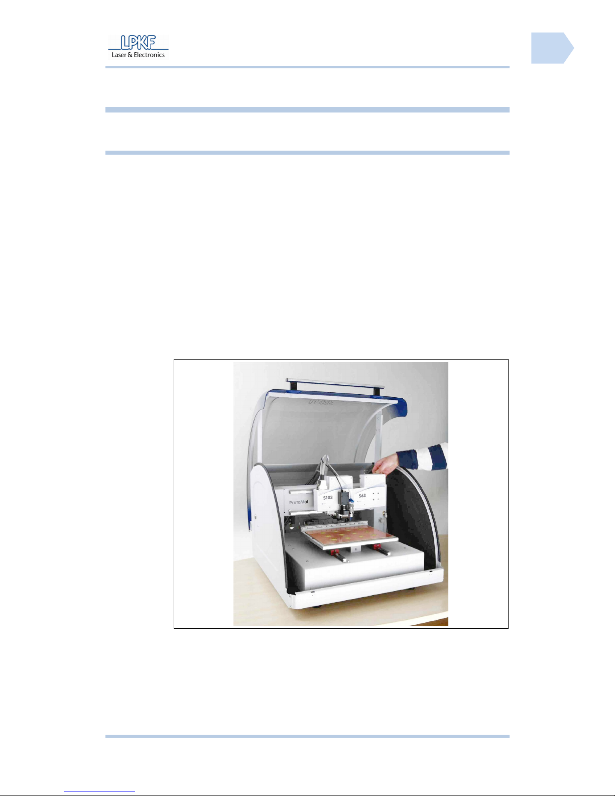
This chapter provides information about the mill/drill potter system ProtoMat S.
1.1 Product characteristics
Using a moving speed of 150 mm/s and a motor speed of 40,000 to 100,000
min
-1
the ProtoMat S produces high-end and complex printed circuit board very
fast and professionally. With a resolution of 0.25 µm this machine provides
highest precision.
The extensive equipment and the high grade of automation as e.g. automatical
exchange of tools, head illumination and a camera for detection of fiducials
make the ProtoMat S extremely comfortable in its operation. The modern and
ergonomically shaped soundproof housing facilitates easy handling. The safe
and comfortable employment of the circuit board plotter is thus possible in any
working environment without any additional effort.
As an optional accessory you can easily install a camera, a vacuum table and a
status light.
The ProtoMat S is controlled using the easy to operate software CircuitPro.
Moreover the software is able to import several CAD formats and to generate
production data from these files.
Fig. 1: ProtoMat S
series
Page 12
Product description ProtoMat S
10 HB V0.9/Mrz-11 © 2011 LPKF AG
1
Pos: 2 /ED_Technische_Dokumentation/2_Bedienung sanleitung/Maschine/ RP_Fräsbohrplo tter/ProtoMat_S_S erie/ProtoMat_S_Ser ie_IIG/Kapitel_1 _Produktbeschr eibung/1_2_Typensc hild @ 0\mod_1254482520 905_2058.docx @ 3583 @ 2
1.2 Type label
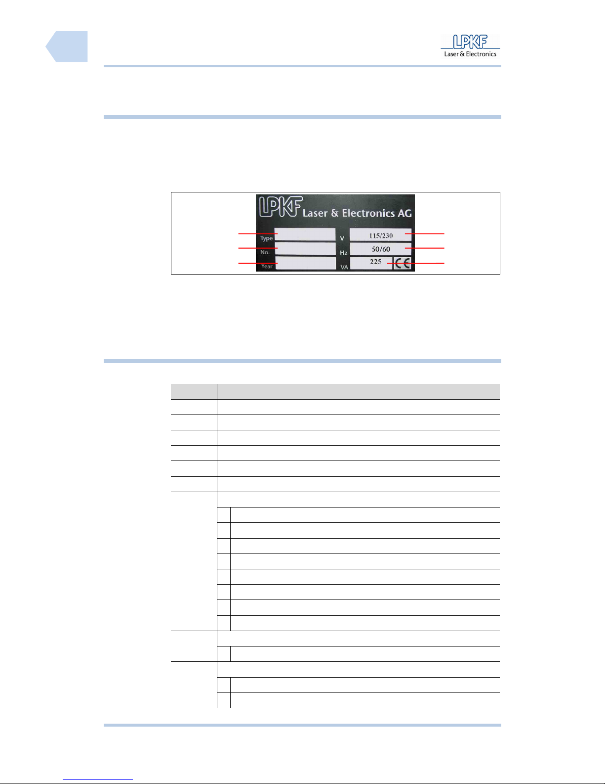
The type label is located at the right side of the machine housing besides the
mains switch.
If any questions occur concerning identification of your machine and the
corresponding equipment please always quote the serial number according to
the type label to the LPKF service.
Pos: 3 /ED_Technische_Dokumentation/2_Bedienung sanleitung/Maschine/ RP_Fräsbohrplo tter/ProtoMat_S_S erie/ProtoMat_S_Ser ie_IIG/Kapitel_1 _Produktbeschr eibung/1_3_Lieferu mfang @ 0\mod_125448339719 7_2058.docx @ 3587 @ 23344
1.3 Scope of delivery
The scope of delivery of the ProtoMat S Series includes:
Tab. 1: Scope of
delivery
Quantity Description
1 ProtoMat S series, inclusive sound proof housing
1 Power cable with safety plug (230 V AC), length 1,5 m
1 Power cable with US plug (115 V AC), length 1,5 m
1 USB connection cable, 5 m
1 Drill underlay material with the dimensions 229 x 305 mm (9 x 12“)
1 Base material FR4 with the dimensions 229 x 305 mm (9 x 12“)
1 Tool set with:
2 Reference hole stripes
5 Reference hole pivots (3 x 8 mm)
1 Force fitting tool for reference hole pivots
4 Fuses 10 A (T10L 250 V)
2 Reference hole drill, spiral drill 2.95 mm
1 Fixing tape (to be dissolved residual-free)
1 Maintenance and service set
1 Solder Paste cartridge for machines with dispense set
1 CD-ROM
1 Software CircuitPro
1 Set of operation manuals, consisting of
1 Operating manual CircuitPro
1 Operating manual ProtoMat S
Fig. 2: Type plate
/1/ Machine type /4/ Operating voltage
/2/ Serial number /5/ Mains frequency in Hz
/3/ Year of production /6/ Power consumption in VA
1
2
3
4
5
6
Page 13
ProtoMat S Product description
© 2011 LPKF AG HB V0.9/Mrz-11 11
1
1.3.1 Accessories
The following components can be delivered as accessories:
Tab. 2:
Accessories
Quantity Description
1 Tool set 1/8“
1 HF tool set 1/8“
1 Dust extraction with auto switch feature
1 Vacuum table to fix work pieces
1 Vision System for detection of fiducials
1 Measuring microscope to check milling tracks and drillings
1 Status Light
1.3.2 Provided components of the operator
The following components are not included in the delivery and have to be
provided by the operator.
1.3.2.1 Control computer
A control computer with the following characteristics has to be supplied by the
operator:
Tab. 3: PC data
Component Rating
CPU IBM compatible from Intel Pentium IV or higher
(comparable to Dual Core 2 GHz)
RAM At least 1 GB DDR2 RAM
Hard disk 2 GB free space on internal disk
Graphic board NVIDEA with at least 512 MB graphics memory
Screen resolution 1280 x 1024 / High Colour (16 Bit)
Monitor 17“ VGA colour monitor
Page 14
Product description ProtoMat S
12 HB V0.9/Mrz-11 © 2011 LPKF AG
1
1.3.2.2 Dust extraction
A dust extraction with the following characteristics has to be supplied by the
operator:
Tab. 2: Data for
dust extraction
Attribute Data
Exhaust power 0 - 280 m3/h
Low pressure 20,000 Pa
Connecting adapter Ø 50 mm
Sound level 62 dB (A)
Collection efficiency > 98 %
Power consumption 1.1 kW
Note
We recommend using a dust extraction unit type LPKF Air
Management System.
Page 15

ProtoMat S Product description
© 2011 LPKF AG HB V0.9/Mrz-11 13
1
Pos: 4 /ED_Technische_Dokumentation/2_Bedienung sanleitung/Maschine/ RP_Fräsbohrplo tter/ProtoMat_S_S erie/ProtoMat_S_Ser ie_IIG/Kapitel_1 _Produktbeschr eibung/1_4_Herste ller @ 0\mod_125500790812 0_2058.docx @ 3741 @ 2
1.4 Manufacturer
LPKF
LPKF Laser & Electronics AG
Osteriede 7
D-30827 Garbsen
Germany
Phone +49 (0)5131 - 70 95 – 0
Fax +49 (0)5131 - 70 95 - 90
Email [email protected]
Internet http://www.lpkf.com
LPKF Service
LPKF Laser & Electronics AG
Service Rapid Prototyping
Osteriede 7
D-30827 Garbsen
Germany
Phone +49 (0)5131 - 70 95 - 0
Fax +49 (0)5131 - 70 95 - 90
Email [email protected]
Internet http://www.lpkf.de/support/index.htm
Page 16

Product description ProtoMat S
14 HB V0.9/Mrz-11 © 2011 LPKF AG
1
Pos: 5 /ED_Technische_Dokumentation/2_Bedienung sanleitung/Maschine/ RP_Fräsbohrplo tter/ProtoMat_S_S erie/ProtoMat_S_Ser ie_IIG/Kapitel_1 _Produktbeschr eibung/1_5_EU-Konfor mitätserklärung @ 0\mod_1255007957167_ 2058.docx @ 3745 @ 2333
1.5 EC declaration of conformity
1.5.1 ProtoMat S43
EC declaration of conformity in accordance with machinery directive 2006/42/EG,
Appendix II A
The manufacturer/seller
LPKF Laser & Electronics AG
Osteriede 7
30827 Garbsen
Germany
hereby declares that the following product
Product name LPKF ProtoMat S43
Product type: Mill/drill plotter
conforms to the provisions of the directive identified above – including the
modifications effective at the time of this declaration.
This declaration refers to the product status where the product was placed on
the market. Parts or modifications installed afterwards by the operator are not
taken into consideration. Any subsequent modification shall invalidate the
declaration for this product.
The following harmonized standards are applied:
EN 60204-1:2007 Safety of machinery - Electrical equipment of
machines - Part 1: General requirements
The following domestic and international standards (or parts/clauses of this
standards) and specifications are applied:
EN ISO 12100-2:2004 Safety of machinery - Basic concepts,
general principles for design - Part 2:
Technical principles
EN ISO 12100-1:2004 Safety of machinery - Basic concepts,
general principles for design - Part 1: Basic
terminology, methodology
EN ISO 14121-1:2007 Safety of machinery - Risk assessment -
Part 1: Principles (ISO 14121-1:2007)
We maintain a quality assurance system according to DIN EN ISO 9001 that
has been certified by DeuZert - Certification number: A 40583 22 00 1.
Person authorized to compile the documentation: Rainer Aschenbeck
Address of the person: see manufacturer address
Page 17

ProtoMat S Product description
© 2011 LPKF AG HB V0.9/Mrz-11 15
1
The following EC guidelines are applied:
• EMC guideline 2004/108/EG
• Directive 2006/95/EC relating to electrical equipment designed for use
within certain voltage limits
Location: Garbsen
Date: 28. March 2011
Bernd Lange
(CTO)
Page 18

Product description ProtoMat S
16 HB V0.9/Mrz-11 © 2011 LPKF AG
1
1.5.2 ProtoMat S63
EC declaration of conformity in accordance with machinery directive 2006/42/EG,
Appendix II A
The manufacturer/seller
LPKF Laser & Electronics AG
Osteriede 7
30827 Garbsen
Germany
hereby declares that the following product
Product name LPKF ProtoMat S63
Product type: Mill/drill plotter
conforms to the provisions of the directive identified above – including the
modifications effective at the time of this declaration.
This declaration refers to the product status where the product was placed on
the market. Parts or modifications installed afterwards by the operator are not
taken into consideration. Any subsequent modification shall invalidate the
declaration for this product.
The following harmonized standards are applied:
EN 60204-1:2007 Safety of machinery - Electrical equipment of
machines - Part 1: General requirements
The following domestic and international standards (or parts/clauses of this
standards) and specifications are applied:
EN ISO 12100-2:2004 Safety of machinery - Basic concepts,
general principles for design - Part 2:
Technical principles
EN ISO 12100-1:2004 Safety of machinery - Basic concepts,
general principles for design - Part 1: Basic
terminology, methodology
EN ISO 14121-1:2007 Safety of machinery - Risk assessment -
Part 1: Principles (ISO 14121-1:2007)
We maintain a quality assurance system according to DIN EN ISO 9001 that
has been certified by DeuZert - Certification number: A 40583 22 00 1.
Person authorized to compile the documentation: Rainer Aschenbeck
Address of the person: see manufacturer address
Page 19

ProtoMat S Product description
© 2011 LPKF AG HB V0.9/Mrz-11 17
1
The following EC guidelines are applied:
• EMC guideline 2004/108/EG
• Directive 2006/95/EC relating to electrical equipment designed for use
within certain voltage limits
Location: Garbsen
Date: 28. March 2011
Bernd Lange
(CTO)
Page 20

Product description ProtoMat S
18 HB V0.9/Mrz-11 © 2011 LPKF AG
1
1.5.3 ProtoMat S103
EC declaration of conformity in accordance with machinery directive 2006/42/EG,
Appendix II A
The manufacturer/seller
LPKF Laser & Electronics AG
Osteriede 7
30827 Garbsen
Germany
hereby declares that the following product
Product name LPKF ProtoMat S103
Product type: Mill/drill plotter
conforms to the provisions of the directive identified above – including the
modifications effective at the time of this declaration.
This declaration refers to the product status where the product was placed on
the market. Parts or modifications installed afterwards by the operator are not
taken into consideration. Any subsequent modification shall invalidate the
declaration for this product.
The following harmonized standards are applied:
EN 60204-1:2007 Safety of machinery - Electrical equipment of
machines - Part 1: General requirements
The following domestic and international standards (or parts/clauses of this
standards) and specifications are applied:
EN ISO 12100-2:2004 Safety of machinery - Basic concepts,
general principles for design - Part 2:
Technical principles
EN ISO 12100-1:2004 Safety of machinery - Basic concepts,
general principles for design - Part 1: Basic
terminology, methodology
EN ISO 14121-1:2007 Safety of machinery - Risk assessment -
Part 1: Principles (ISO 14121-1:2007)
We maintain a quality assurance system according to DIN EN ISO 9001 that
has been certified by DeuZert - Certification number: A 40583 22 00 1.
Person authorized to compile the documentation: Rainer Aschenbeck
Address of the person: see manufacturer address
Page 21

ProtoMat S Product description
© 2011 LPKF AG HB V0.9/Mrz-11 19
1
The following EC guidelines are applied:
• EMC guideline 2004/108/EG
• Directive 2006/95/EC relating to electrical equipment designed for use
within certain voltage limits
Location: Garbsen
Date: 28. March 2011
Bernd Lange
(CTO)
Page 22

Product description ProtoMat S
20 HB V0.9/Mrz-11 © 2011 LPKF AG
1
Page 23
ProtoMat S Safety notes
© 2011 LPKF AG HB V0.9/Mrz-11 21
2
Pos: 6 /ED_Technische_Dokumentation/2_Bedienung sanleitung/Maschine/ RP_Fräsbohrplo tter/ProtoMat_S_S erie/ProtoMat_S_Ser ie_IIG/Kapitel_2 _Sicherheitshin weise/2_1_Gerätesi cherheit @ 0\mod_125440 6707494_2058.doc x @ 3552 @ 12
2 Safety notes
The following chapter lists the most important safety notes for working with the
machine and the corresponding control software.
2.1 Device safety
WARNING
Danger to life due to electrical shock!
Missing or inadequate electrical grounding may cause deadly
current strokes and/or fire.
The machine must operate connected with a tested protective
earth contact socket and the correct earthing must be checked.
WARNING
Danger to life due to electrical shock!
Missing or inadequate electrical fuse protection may cause
deadly current strokes and/or fire.
Never bypass any fuses! Use only the fuses recommended by
the manufacturer.
ATTENTION
Health hazard!
During machining of work parts harmful fine particles and gases
may develop that can be inhaled!
Make sure that dust extraction is activated during machining of
the work piece. Use fine particle filters exclusively.
ATTENTION
Risk of injury!
The machine is heavy and bulky, thus it cannot be carried, be
lifted or transported by only one person!
Lift and transport the machine always with two persons.
ATTENTION
Risk of injury!
Any accidental starting of the motor and moving of the mill/drill
head during repairs and servicing may cause considerable
injuries.
Make sure that only one person operates the machine. Secure
the machine during servicing and repair activities appropriate.
Page 24
Safety notes ProtoMat S
22 HB V0.9/Mrz-11 © 2011 LPKF AG
2
ATTENTION
Risk of injury!
During the machining process the used tools and the collet
chuck heat up so that direct contact may cause burn-ups.
Use safety gloves and a pair of tweezers during manual
exchange of tools during operation.
ATTENTION
Risk of injury!
The employed tools are sharp-edged and cause cuts and stab
wounds whenever used improperly.
Always store the tools in their toolbox and protect the toolbox
against unauthorised usage.
ATTENTION
Risk of injury!
The opened soundproof cover may close accidentally and jam
fingers or the complete hand.
Always lift the soundproof cover up to the latching position and
secure the machine against any shocks.
ATTENTION
Risk of injury!
An instable level surface can collapse and hurt the operator
during machining of a work piece due to vibrations and the
machine powers.
The machine must be placed on a solid surface.
Page 25
ProtoMat S Safety notes
© 2011 LPKF AG HB V0.9/Mrz-11 23
2
Pos: 7 /ED_Technische_Dokumentation/2_Bedienung sanleitung/Maschine/ RP_Fräsbohrplo tter/ProtoMat_S_S erie/ProtoMat_S_Ser ie_IIG/Kapitel_2 _Sicherheitshin weise/2_2_Allge meine_Sicherheitshin weise @ 0\mod_1254413988 782_2058.docx @ 3555 @ 2
2.2 General safety notes
General safety notes
Observe any legal accident prevention and labour
protection regulations.
Observe the accident prevention and labour protection
regulations given by the employer or the industrial union.
Read the operation manual before start up the machine and
any usage of the machine. Contact the LPKF service if any
problems occur!
The machine must exclusively be operated, repaired and
serviced by qualified and authorised staff.
Please wear adequate work clothes respective protective
clothing when working at the machine.
Use the machine only according to intended usage.
Never operate the machine in an environment with danger
of fire or explosions.
Only operate the machine in proper condition. Make a
visual check before any usage and replace faulty cables
and tubes at once.
Only operate the machine with correct operating protective
devices.
Only operate the machine with tools and accessories
licensed by LPKF.
Perform the required service and repair procedure
according to the described periods.
Separate the machine from mains power supply whenever
you have to perform repairs or servicing.
Always remove damages or functional disturbances at the
machine at once. Put the machine out of service and secure
it against further usage whenever the damage cannot be
removed.
Remove dust and remains of material using a paint brush
or draw off any machining remains. Never use compressed
air to clean the machine!
Dispose of machining remains according to legal
regulations.
Make sure that your work space is always clean.
Always keep children away from the work space.
Page 26

Safety notes ProtoMat S
24 HB V0.9/Mrz-11 © 2011 LPKF AG
2
Page 27

ProtoMat S Functional description
© 2011 LPKF AG HB V0.9/Mrz-11 25
3
Pos: 8 /ED_Technische_Dokumentation/2_Bedienung sanleitung/Maschine/ RP_Fräsbohrplo tter/ProtoMat_S_S erie/ProtoMat_S_Ser ie_IIG/Kapitel_3 _Funktionsbesc hreibung/3_1_Funktio n @ 0\mod_1254730740545_ 2058.docx @ 3600 @ 123
3 Functional description
In the following chapter the function of the circuit board plotter is described in
detail.
3.1 Function
The circuit board plotter ProtoMat S is employed for processing of electrical
printed circuit boards. Printed circuit boards can consist of several layers
(multilayer) and may have up to six layers. In addition the ProtoMat S can be
employed for processing of signs or housing components (front plate).
The circuit board plotter can be used for the following machining processes:
● Milling and drilling of single or double sided base material
● Milling and drilling of multilayer materials
● Milling of SMD soldering paste stencils
● Milling of solder resist masks
● Engraving of signs or housing plates
● Milling of cut-outs and outlines
● Perforating of planar materials
3.1.1 Permitted machining materials
For reliable and safe operation of the circuit board plotter ProtoMat S we
recommend original LPKF consumables. These articles are available with good
value as multilayer sets or they are sold as single material for the different
applications.
Tab. 4: Machining materials
Designation Contents Usage
FR4 base material,
copper-clad
FR4 base material 1,5 mm, 229 x
305 mm (9 x 12“), with or without
protective foil, 3 mm reference
hole drillings
Production of single or double sided
circuit boards
Multilayer set Base material, surface laminate,
prepreg, seal rings
Production of multilayer circuit boards
i.e. further processing with the LPKF
multilayer press Multipress S
Drilling underlay Drilling underlay, format DIN A4, 2
mm
Protection of the working table during
drilling or during material penetrating
drilling
Sinter plate Air permeable sinter plate for
vacuum table (optional)
Work plate or drilling underlay for the
vacuum table (optional)
Cleaning pad Metal-free cleaning pads Removal of oxidation remains on
copper coatings
Pos: 9 /ED_Technische_Dokumentation/2_Bedienung sanleitung/Maschine/ RP_Fräsbohrplo tter/ProtoMat_S_S erie/ProtoMat_S_Ser ie_IIG/Kapitel_3 _Funktionsbesc hreibung/3_2_Geräteauf bau @ 0\mod_12547406048 62_2058.docx @ 3608 @ 233344
Page 28
Functional description ProtoMat S
26 HB V0.9/Mrz-11 © 2011 LPKF AG
3
3.2 Equipment design
ProtoMat S series circuit board plotters are constructed equally in principle to
facilitate upgrades as simple as possible.
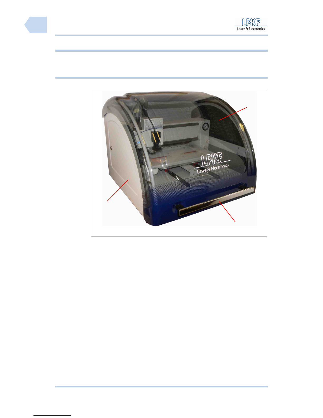
3.2.1 Housing
Fig. 3: Front view
/1/ Soundproof housing /2/ Cover knob
/3/ Soundproof cover
1
2
3
Page 29
ProtoMat S Functional description
© 2011 LPKF AG HB V0.9/Mrz-11 27
3
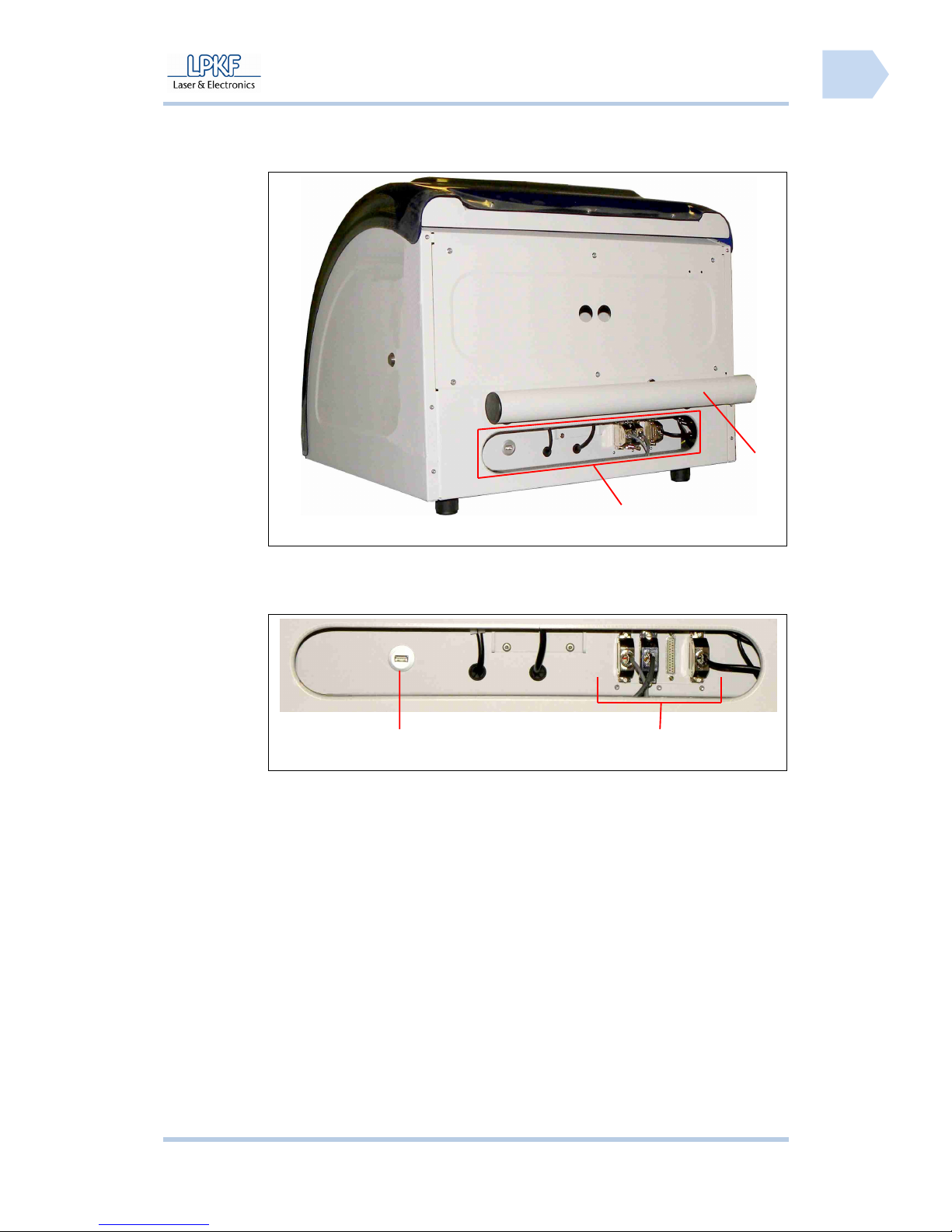
Fig. 4: Back view
/1/ Interfaces /2/ Suction pipe with connector for
extraction tube
Fig. 5: Interfaces
/1/ USB port /2/ LPKF ports (4 x SUB-D, 25 pin.)
1
1
2
2
Page 30
Functional description ProtoMat S
28 HB V0.9/Mrz-11 © 2011 LPKF AG
3
3.2.2 Working area
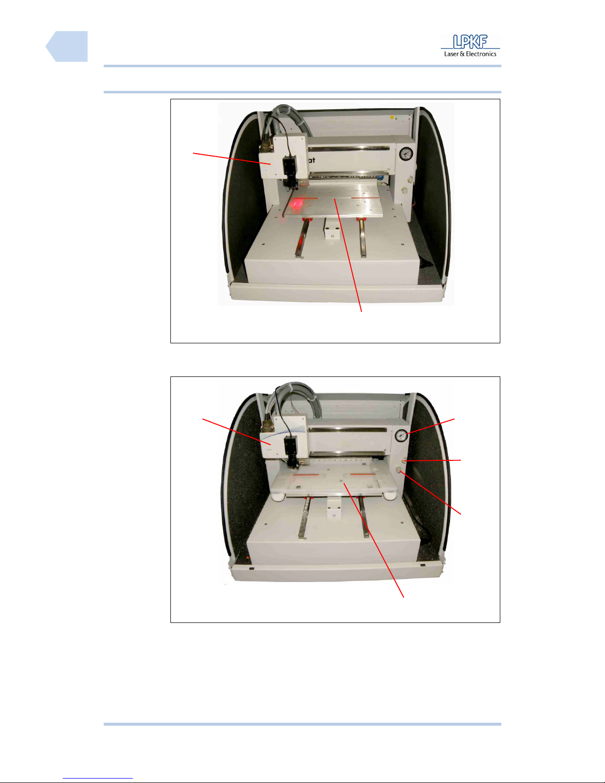
Fig. 6: Working
table
/1/ Mill/drill head /2/ Working table
Fig. 7: Vacuum
table
/1/ Mill/drill head /4/ Connector
/2/ Vacuum table /5/ Pressure meter
/3/ Vacuum control unit
2
1
1
2
3
4
5
Page 31
ProtoMat S Functional description
© 2011 LPKF AG HB V0.9/Mrz-11 29
3
3.2.3 Mill/drill head
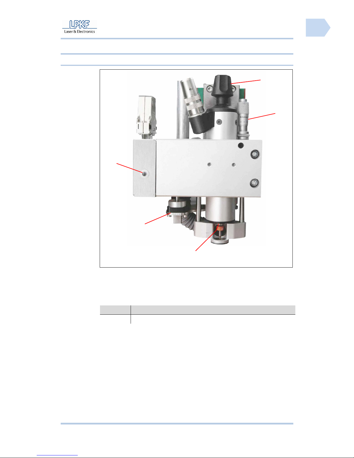
3.2.3.1 ProtoMat S43
Fig. 8: Mill/drill
head
ProtoMat S43
/1/ Status LED /4/ Milling depth adjustment (manual)
/2/ Manual Z direction adjustment /5/ Open/close collet chuck (manual)
/3/ Tool holder
Tab. 5: LED
signalling
ProtoMat S43
LED Signal
ON The circuit board plotter is ready for operation.
1
2
3
4
5
Page 32
Functional description ProtoMat S
30 HB V0.9/Mrz-11 © 2011 LPKF AG
3
3.2.4 Mill/drill head
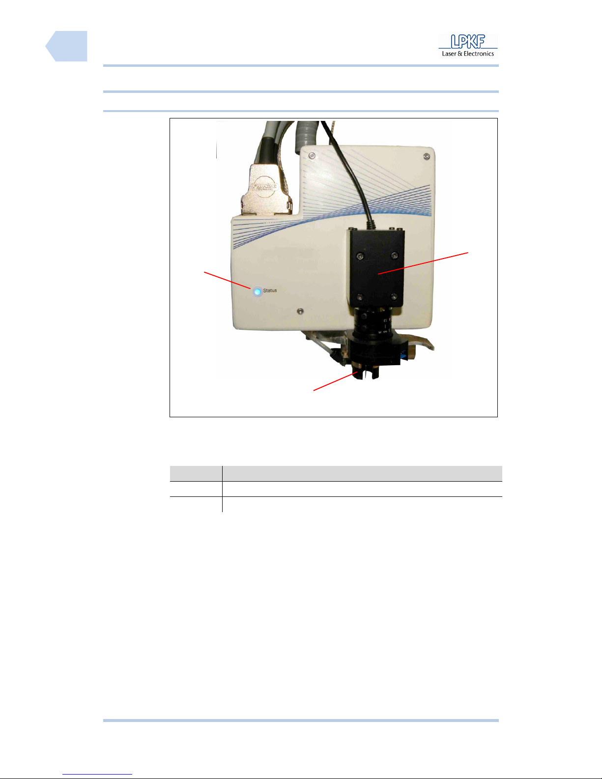
3.2.4.1 ProtoMat S63/103
Fig. 9: Mill/drill
head ProtoMat
S63/S103
/1/ Status LED /2/ Tool holder
/3/ Camera
Tab. 2: LED
signalling
ProtoMat S63/
S103
LED Signal
ON The circuit board plotter is ready for operation.
Flash The collet chuck is moving.
1
2
3
Page 33
ProtoMat S Functional description
© 2011 LPKF AG HB V0.9/Mrz-11 31
3
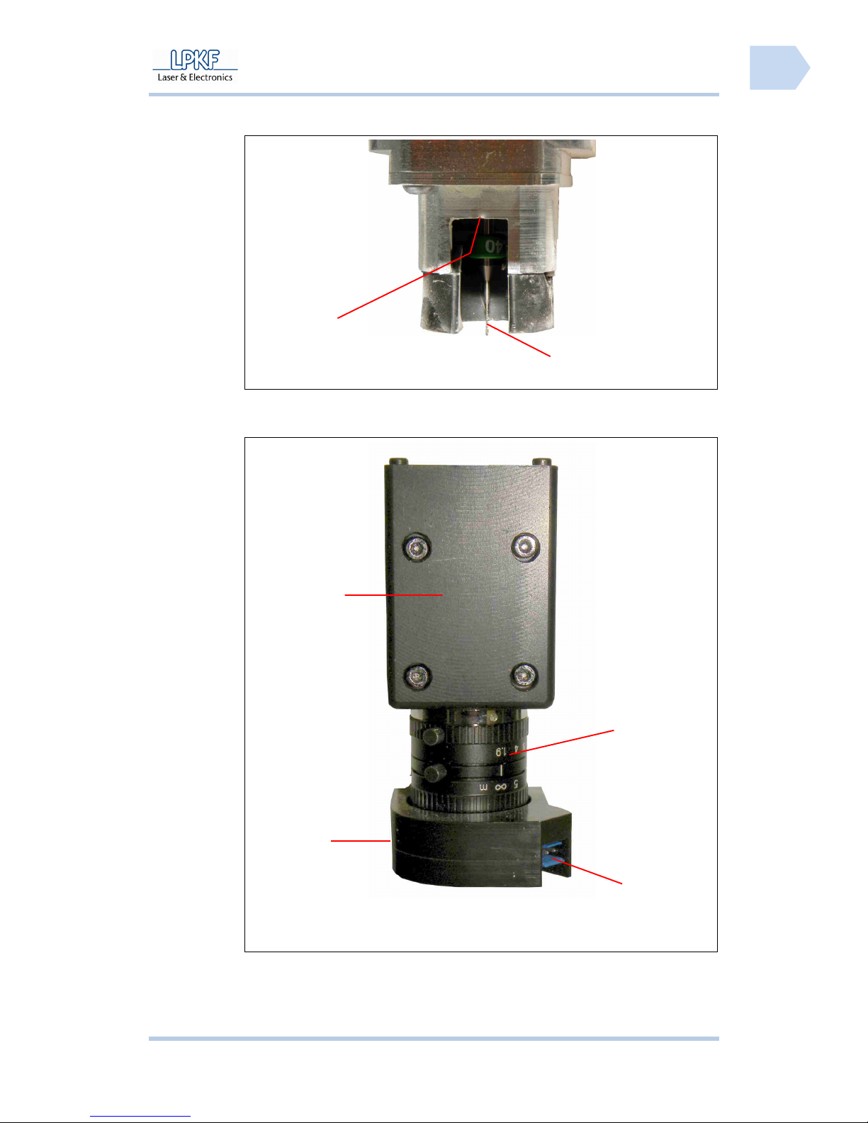
Fig. 10: Tool
holder unit
/1/ Tool holder /2/ Tool (e. g. Spiral drill 0.2 mm)
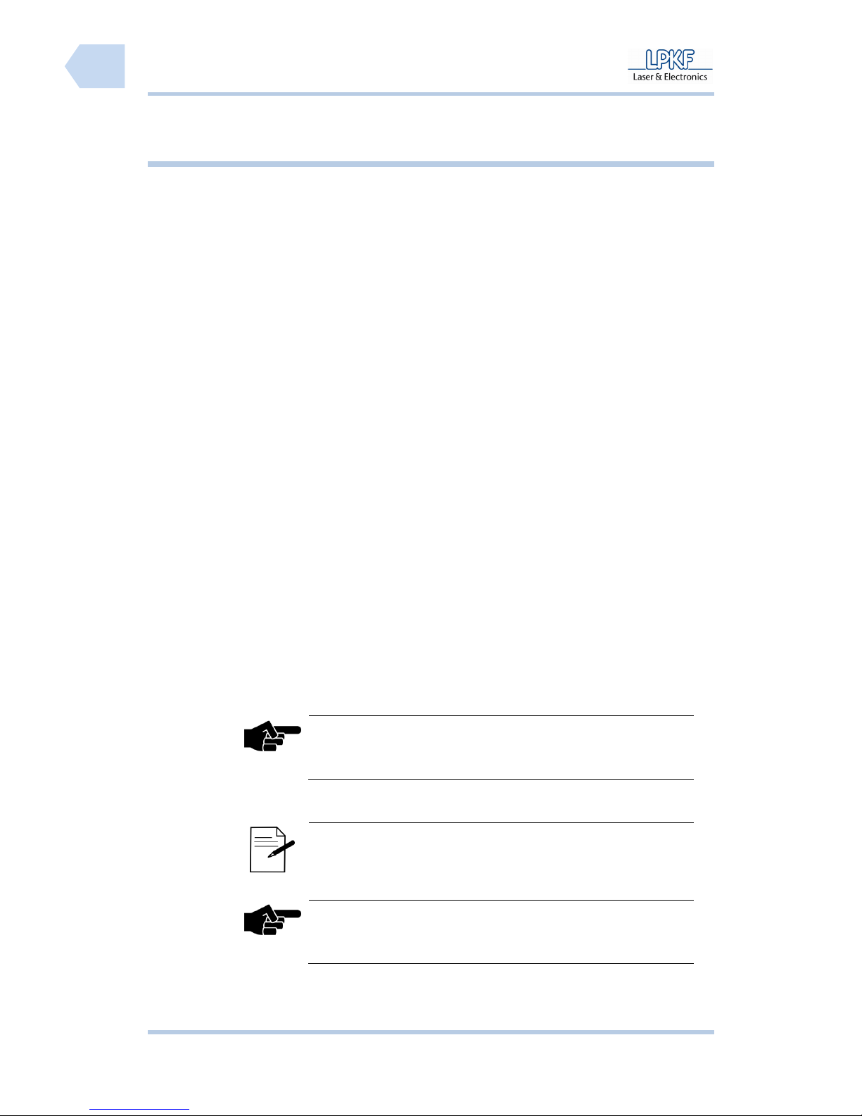
Fig. 11: Camera
/1/ Camera /3/ Connector for dispenser
/2/ Ring light /4/ Objective
1
2
1
4
2
3
Page 34
Functional description ProtoMat S
32 HB V0.9/Mrz-11 © 2011 LPKF AG
3
Pos: 10 /ED_Technische_Dokumentation/2_Bedienungsa nleitung/Maschi ne/RP_Fräsbohrplot ter/ProtoMat_S_Ser ie/ProtoMat_S_Ser ie_IIG/Kapite l_3_Funktionsbesc hreibung/3_3_Besti mmungsgemäßer_Gebrauc h @ 0\mod_12547334896 08_2058.docx @ 3604 @ 23
3.3 Conditions of use
The circuit board plotter can be used for production of single and multi-sided
circuit boards. Processing of signs as well as housing parts e.g. back or front
plates are acceptable likewise.
Permitted machining processes are:
● Milling and drilling of single and double sided base material
● Milling and drilling of multilayer material
● Milling of SMD soldering paste stencils
● Milling of solder resist mask
● Engraving of signs or housing plates
● Perforation of flat materials
● Milling of cut-outs and outlines
The following materials are permitted for this circuit board plotter:
● GFK or CFK base material
● PTFE or ceramic-filled base material
● Wood
● Nonferrous materials as:
- Aluminium acc. to DIN EN 573:EN AW-6012
- Brass acc. to DIN EN 1412: CW603N
● Plastics as:
- Polyoxymethylen
- ABS-Copolymere
The circuit board plotter may only be operated for the machining processes and
materials listed in this chapter.
The circuit board plotter may only be operated using the delivered control
software CircuitPro.
Note
Please contact the LPKF service at once if you wish to use an
other control software as the delivered item!
The circuit board plotter may only be start up with a sufficient dust extraction
and a fine particle filtering.
Memo
We recommend the LPKF dust extraction system with
integrated HEPA filter.
Note
Please contact the LPKF service first if you plan to use an
other dust extraction system.
Page 35

ProtoMat S Functional description
© 2011 LPKF AG HB V0.9/Mrz-11 33
3
The circuit board plotter may not be used for processing of highly combustible
materials, closed containers, hollow articles, textiles and foods. Any processing
of bodily parts (e.g. fingernails) is not allowed.
Note
Always contact the LPKF service first if you are not sure if the
used materials can be processed with the circuit board plotter.
3.3.1 Disclaimer
The circuit board plotter was developed and produced according to state of the
art technology and approved safety-related regulations. However improper use
or application may cause hazards for body and life of the operator or third
persons or impairments of the device or other material assets.
The manufacturer is not liable for damages that occur by improper use or the
following type of handlings:
● Improper handling, inclusive any applications not mentioned in this
manual
● Applications in improper environments
● Installation and operation with insufficiently trained and informed staff
or unauthorised persons
● Nonobservance of legal safety and work protection regulations
● Nonobservance of technical information
● Incorrect installation
● Insufficient mains power supply
● Unimplemented or insufficient maintenance
● Unauthorised technical modifications
● Employment of components or materials or spare parts that are not
specially licensed for this circuit board plotter
Page 36

Functional description ProtoMat S
34 HB V0.9/Mrz-11 © 2011 LPKF AG
3
Pos: 11 /ED_Technische_Dokumentation/2_Bedienungsa nleitung/Maschi ne/RP_Fräsbohrplot ter/ProtoMat_S_Ser ie/ProtoMat_S_Ser ie_IIG/Kapite l_3_Funktionsbesc hreibung/3_4_Techni sche_Daten @ 0\mod_1254 740954986_2058.doc x @ 3612 @ 2333
3.4 Technical Data
3.4.1 ProtoMat S43
Technical data circuit board plotter type ProtoMat S43:
Tab. 6: Technical
data ProtoMat
S43
Data Values
Mains power supply Voltage range from 110 to 240 V AC, 50 - 60 Hz
Power consumption 200 W
Weight Appr. 58 kg
Dimension 670 x 540 x 760 mm (W x H x D)
Permissible ambient temperature Range from 15 to 25 °C
Permissible atmospheric humidity Up to 60 %
Workplace noise level 71 dB (A), devoid of noise level dust extraction
Motor mill/drill head Three phase motor
Range of speeds Up to 40,000 min-1 (variable)
Processing speed 150 mm/s
Drilling capacity 150 strokes per minute
Tool change mechanism Manually
Number of tools Up to 15, software limit
Tool collet base 3.175 mm (1/8“)
Motor X-axis Three phase stepping motor
Motor Y-axis Three phase stepping motor
Motor Z-axis Two phase stepping motor
Milling depth adjustment Manually
Working area for work table 305 x 229 x 5 mm (X x Y x Z)
Working area for vacuum table 305 x 229 x 25 mm (X x Y x Z)
Resolution (X/Y) +/- 1 µm (0.04 Mil)
Repeat accuracy +/- 5 µm (0.2 Mil)
Exactness reference hole system +/- 20 µm (0.8 Mil)
Minimal drill diameter 0.2 mm
Page 37

ProtoMat S Functional description
© 2011 LPKF AG HB V0.9/Mrz-11 35
3
3.4.2 ProtoMat S63
Technical data circuit board plotter type ProtoMat S63:
Tab. 7: Technical
data ProtoMat
S63
Data Values
Mains power supply Voltage range from 110 to 240 V AC, 50 - 60 Hz
Power consumption 200 W
Weight Appr. 58 kg
Dimension 670 x 540 x 760 mm (W x H x D)
Permissible ambient temperature Range from 15 to 25 °C
Permissible atmospheric humidity Up to 60 %
Workplace noise level 71 dB (A), devoid of noise level dust extraction
Motor mill/drill head Three phase motor
Range of speeds Up to 60,000 min-1 (variable)
Processing speed 150 mm/s
Drilling capacity 150 strokes per minute
Tool change mechanism Automatically
Number of tools Up to 15 tool holder positions, software limit
Tool collet base 3.175 mm (1/8“)
Motor X-axis Three phase stepping motor
Motor Y-axis Three phase stepping motor
Motor Z-axis Two phase stepping motor
Milling depth adjustment Automatically
Working area work table 305 x 229 x 38 mm (X x Y x Z)
Working area vacuum table 305 x 229 x 25 mm (X x Y x Z)
Resolution (X/Y) +/- 0.25 µm (0.01 Mil)
Repeat accuracy +/- 5 µm (0.2 Mil)
Exactness reference hole system +/- 20 µm (0.8 Mil)
Minimal drill diameter 0.2 mm
Page 38

Functional description ProtoMat S
36 HB V0.9/Mrz-11 © 2011 LPKF AG
3
3.4.3 ProtoMat S103
Technical data circuit board plotter type ProtoMat S103:
Tab. 8: Technical
data ProtoMat
S103
Data Values
Mains power supply Voltage range from 110 to 240 V AC, 50 - 60 Hz
Power consumption 300 W
Weight Appr. 60 kg
Dimension 670 x 540 x 760 mm (W x H x D)
Permissible ambient temperature Range from 15 to 25 °C
Permissible atmospheric humidity Up to 60 %
Workplace noise level 71 dB (A), devoid of noise level dust extraction
Motor mill/drill head Three phase motor
Range of speeds Up to 100,000 min-1 (variable)
Processing speed 150 mm/s
Drilling capacity 150 strokes per minute
Tool change mechanism Automatically
Number of tools Up to 15 tool holder positions, software limit
Tool collet base 3.175 mm (1/8“)
Motor X axis Three phase stepping motor
Motor Y axis Three phase stepping motor
Motor Z axis Two phase stepping motor
Milling depth adjustment Automatically
Working area work table 305 x 229 x 38 mm (X x Y x Z)
Working area vacuum table 305 x 229 x 25 mm (X x Y x Z)
Resolution (X/Y) +/- 0.25 µm (0.01 Mil)
Repeat accuracy +/- 5 µm (0.2 Mil)
Exactness reference hole system +/- 20 µm (0.8 Mil)
Minimal drill diameter 0.2 mm
Page 39

ProtoMat S Functional description
© 2011 LPKF AG HB V0.9/Mrz-11 37
3
Pos: 12 /ED_Technische_Dokumentation/2_Bedienungsa nleitung/Maschi ne/RP_Fräsbohrplot ter/ProtoMat_S_Ser ie/ProtoMat_S_Ser ie_IIG/Kapite l_3_Funktionsbesc hreibung/3_5_Emissi onen @ 0\mod_12547432222 09_2058.docx @ 3616 @ 233
3.5 Emissions
3.5.1 Acoustic emission
The permanent acoustic noise and vibration values of the circuit board plotter
do not exceed the legal compulsory acoustic exposition level of 85 dB (A).
Max. noise level
(without soundproof hood and dust
extraction)
71 dB (A)
The noise level depends on the processing material. At a permanent heavy
noise level the operator has to wear an ear protection (one way ear protection
or circumaural headphones).
3.5.2 Material emission
During machining of circuit boards or materials dust or fine particles occur.
These fine particles are, depending on the material, more or less hazardous to
health and must not be expired to the environment. Thus a dust extraction has
to be activated during operation of the circuit board plotter that extracts fine
particles in a fine particle filter.
Pos: 13 /ED_Technische_Dokumentation/2_Bedienungsa nleitung/Maschi ne/RP_Fräsbohrplot ter/ProtoMat_S_Ser ie/ProtoMat_S_Ser ie_IIG/Kapite l_3_Funktionsbesc hreibung/3_6_Schutz _von_Personen @ 0\mod_12 54744675624_2058. docx @ 3620 @ 2
3.6 Protection of persons
Any effective legal and internal work protection measures have to be obeyed.
According to the application and the material to be processed the operator has
to wear appropriate protective clothing, this includes:
● Safety glasses
● Safety gloves
● Ear protection (one-way ear protection or earmuffs)
● Respirator mask
The safety instruction in chapter 2 (see Page 21) have to be obeyed in any
case.
Pos: 14 /ED_Technische_Dokumentation/2_Bedienungsa nleitung/Maschi ne/RP_Fräsbohrplot ter/ProtoMat_S_Ser ie/ProtoMat_S_Ser ie_IIG/Kapite l_3_Funktionsbesc hreibung/3_7_Entsor gung_des_Abfall materials @ 0\mod_12547452 55574_2058.doc x @ 3624 @ 2
3.7 Disposal of waste material
Local laws, directions and regulations as well as company directions concerning
waste of material (fine particles and rest materials) have to be obeyed.
Check disposal with the responsible employee of your company e.g. your
environmental protection representative.
Page 40

Functional description ProtoMat S
38 HB V0.9/Mrz-11 © 2011 LPKF AG
3
Page 41
ProtoMat S Transport and storage
© 2011 LPKF AG HB V0.9/Mrz-11 39
4
Pos: 15 /ED_Technische_Dokumentation/2_Bedienungsa nleitung/Maschi ne/RP_Fräsbohrplot ter/ProtoMat_S_Ser ie/ProtoMat_S_Ser ie_IIG/Kapite l_4_Transport_Lager ung/4_1_Transport @ 0\ mod_1254747966635_2 058.docx @ 3631 @ 1232
4 Transport and storage
The following chapter gives some information concerning transport and storage
of the circuit board plotter.
4.1 Transport
ATTENTION
Risk of injury!
The machine is heavy and bulky and cannot be transported or
lifted by one person!
Lift and transport the machine always with two persons.
For transports at large distances the circuit board plotter has to be stored in the
delivered covering box. The covering box has to be placed and fixed on an euro
pallet.
For transports at short distances the circuit board plotter can be take out of the
covering box to be carried by two persons to the working desk.
4.1.1 Transport lock
Fix the mill/drill head with a transport protection band and place a foam mat
under the mill/drill head.
4.2 Storage
Note
The circuit board plotter has to be stored in its covering box in a
cool and dry environment.
At longer down or storage times, transport locks have to be installed and the
circuit board plotters has to be stored in its covering box. Store the circuit board
plotter in a cool and dry location. Use a protective cover to protect it from dust
and humidity.
Page 42

Transport and storage ProtoMat S
40 HB V0.9/Mrz-11 © 2011 LPKF AG
4
Page 43
ProtoMat S Installation
© 2011 LPKF AG HB V0.9/Mrz-11 41
5
Pos: 16 /ED_Technische_Dokumentation/2_Bedienungsa nleitung/Maschi ne/RP_Fräsbohrplot ter/ProtoMat_S_Ser ie/ProtoMat_S_Ser ie_IIG/Kapite l_5_Installation_I nbetriebnahme/5_ 1_Aufstellungsbedin gungen @ 0\mod_125474 9141057_2058.docx @ 3635 @ 12
5 Installation
In this chapter installation and start up procedure of the circuit board plotter is
described in detail.
5.1 Assembly conditions
ATTENTION
Risk of injury!
An instable underground that crashes may harm operators due
to vibrations and machine powers that may occur during
processing of a work piece.
The machine must be placed on a solid surface.
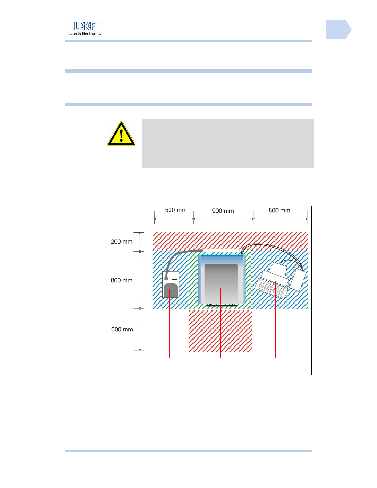
The circuit board plotter has to be installed on a solid work desk with a size of at
least 800 x 900 mm.
Fig. 12: Required
space
/1/ Dust extraction /3/ PC
/2/ Circuit board plotter
The areas marked in red are safety zones that must not be blocked with
objects.
Pos: 17 /ED_Technische_Dokumentation/2_Bedienungsa nleitung/Maschi ne/RP_Fräsbohrplot ter/ProtoMat_S_Ser ie/ProtoMat_S_Ser ie_IIG/Kapite l_5_Installation_I nbetriebnahme/5_ 2_Gerät_auspacken @ 0\ mod_1254753807408_20 58.docx @ 3639 @ 2
1
2
3
Page 44
Installation ProtoMat S
42 HB V0.9/Mrz-11 © 2011 LPKF AG
5
5.2 Unpacking the device
ATTENTION
Risk of injury!
The machine is heavy and bulky and cannot be transported or
lifted by one person!
Lift and transport the machine with two persons.
NOTE
The graphic unpacking instruction is to be found in the covering
box. After having removed the cover of the box you can take the
unpacking instruction and proceed as described.
■
Unpacking the circuit board plotter
1. Transport the euro pallet with a lift truck to the work desk.
2. Remove the adhesive tape from the box cover.
3. Lift the paper cover from the box.
4. Take the unpacking instruction and follow the instructions step by step.
♦ Now the circuit board plotter is unpacked and ready for installation.
Pos: 18 /ED_Technische_Dokumentation/2_Bedienungsa nleitung/Maschi ne/RP_Fräsbohrplot ter/ProtoMat_S_Ser ie/ProtoMat_S_Ser ie_IIG/Kapite l_5_Installation_I nbetriebnahme/5_ 3_Montage_und_Inb etriebnahme @ 0\mod_125475 3952922_2058.doc x @ 3643 @ 23443
5.3 Installation and commissioning
Note
Prerequisite for installation and start of operation is that the PC
and the dust extraction are available at the work place. PC and
dust extraction must be ready for operation.
Note
The control software CircuitPro has to be installed on the PC.
5.3.1 Installation
The installation of the circuit board plotter must be done in four steps:
I. Removal of the transport locks
II. Connection of the mains cable
III. Connection of the dust extraction
IV. Connection of the PC
Page 45
ProtoMat S Installation
© 2011 LPKF AG HB V0.9/Mrz-11 43
5
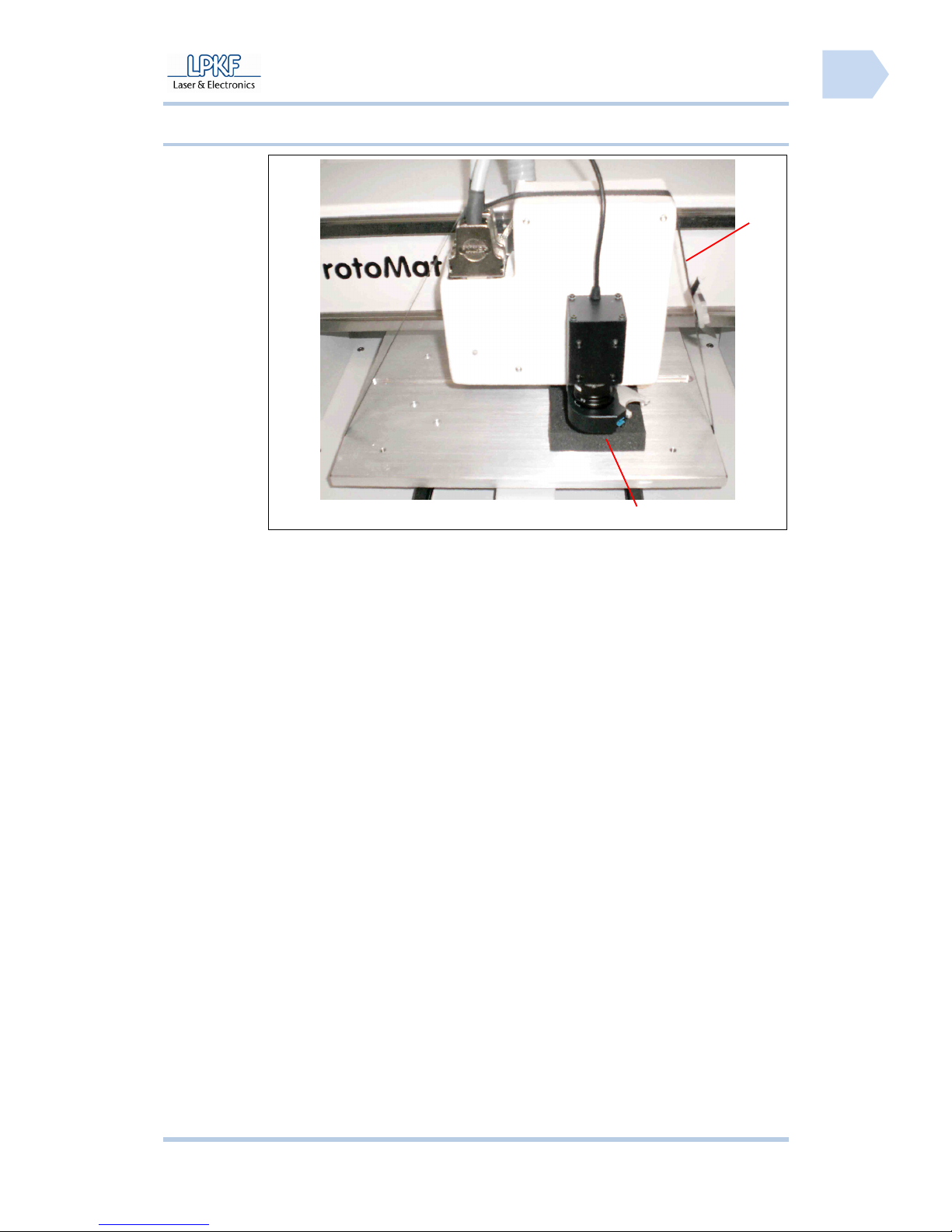
5.3.1.1 Remove the transport lock
Fig. 13: Transport
lock
/1/ Foam mat /2/ Security tape
■ Removal of the transport locks
1. Take a side cutter and open the security tape /2/.
2. Remove the security tape /2/ and dispose it.
3. Remove the foam mat /1/.
♦ The transport locks are removed.
2
1
Page 46
Installation ProtoMat S
44 HB V0.9/Mrz-11 © 2011 LPKF AG
5
5.3.1.2 Connecting the circuit board plotter
Note
The machine must be switched off before any cable can be
connected to the interfaces.
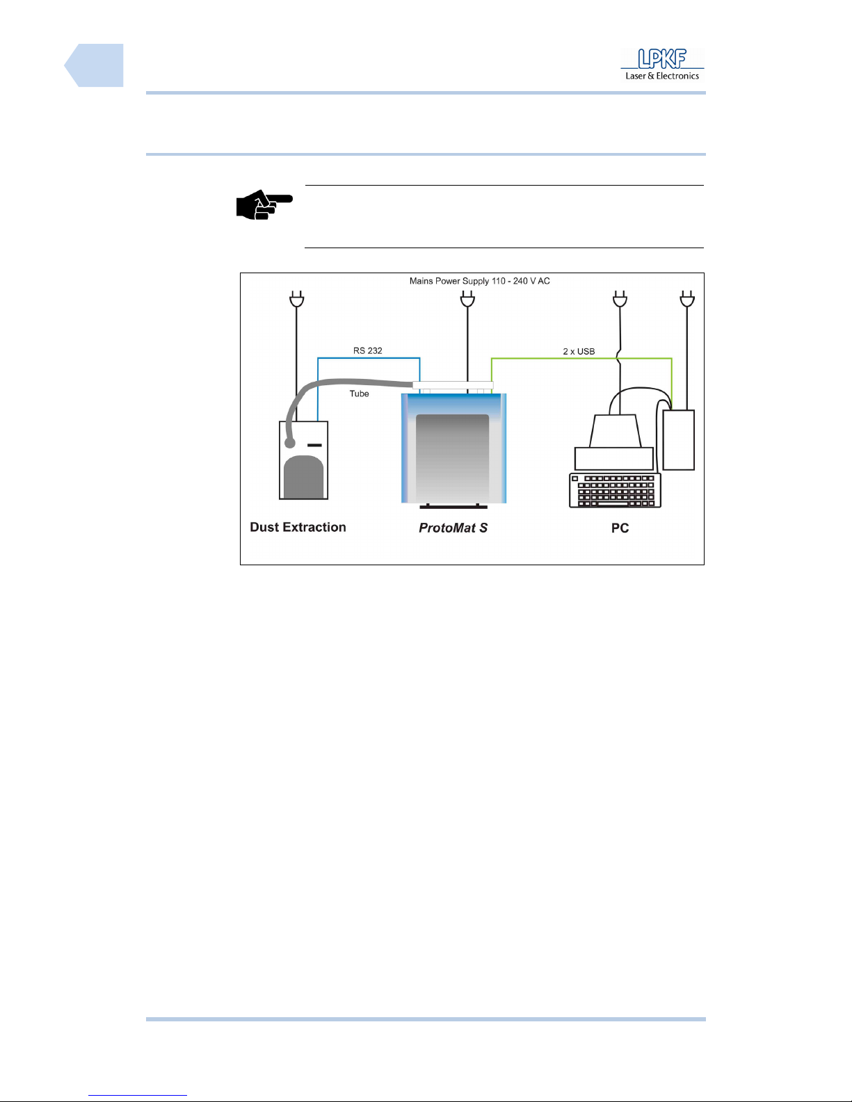
Fig. 14:
Connections
■ Connecting the circuit board plotter
1. Take the delivered USB cable and connect the circuit board plotter to the
PC (free USB slot).
2. If the camera unit is installed take the pre-installed USB cable of the
camera and connect it to the PC (free USB slot).
3. Take the RS232 cable and connect the circuit board plotter to the dust
extraction.
4. Open the soundproof hood of the circuit board plotter.
5. Insert the delivered mains cable into the AC power socket below the main
switch.
6. Guide the mains voltage cable alongside the machine through the gap of
the machine housing.
7. Connect the circuit board plotter with the mains power supply.
8. Connect the PC with the mains power supply.
9. Connect the monitor with the mains power supply.
Page 47
ProtoMat S Installation
© 2011 LPKF AG HB V0.9/Mrz-11 45
5
10. Connect the dust extraction with the mains power supply.
11. Plug the tube of the dust extraction into the suction pipe of circuit board
plotter (rear side).
12. Plug the other side of the tube on the coupler of the dust extraction.
♦ Now the circuit board plotter is connected.
Note
Do not connect any UBB hub to the USB interfaces of the
machine. The USB interface do not support this configuration at
all.
5.3.2 Commissioning
Always activate the system in the same sequence:
I. Switch on the PC (control unit)
II. Switch on the dust extraction and set the operation mode to automatic
or constant operation
III. Switch on the circuit board plotter
■ System start up
1. Switch on the PC.
2. Edit the user name and password.
3. Wait until the OS has booted up completely.
4. Switch on the dust extraction.
5. Turn the operation mode switch into the automatic position.
6. Adjust the desired extraction power.
7. Open the cover of the circuit board plotter.
8. Activate the circuit board plotter by setting the main switch to position I
(ON).
9. Close the cover.
10. Start CircuitPro.
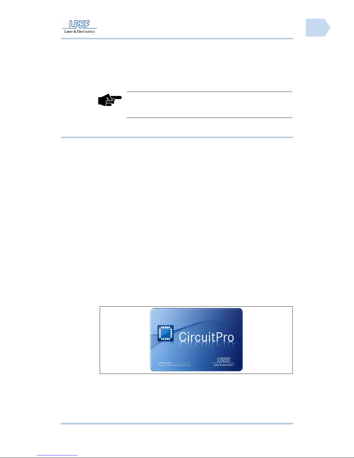
➨ The CircuitPro start-up logo is displayed:
Fig. 15: Start-up
Logo
♦ The circuit board plotter is ready.
Page 48
Installation ProtoMat S
46 HB V0.9/Mrz-11 © 2011 LPKF AG
5
5.3.3 Remove the dummy tool
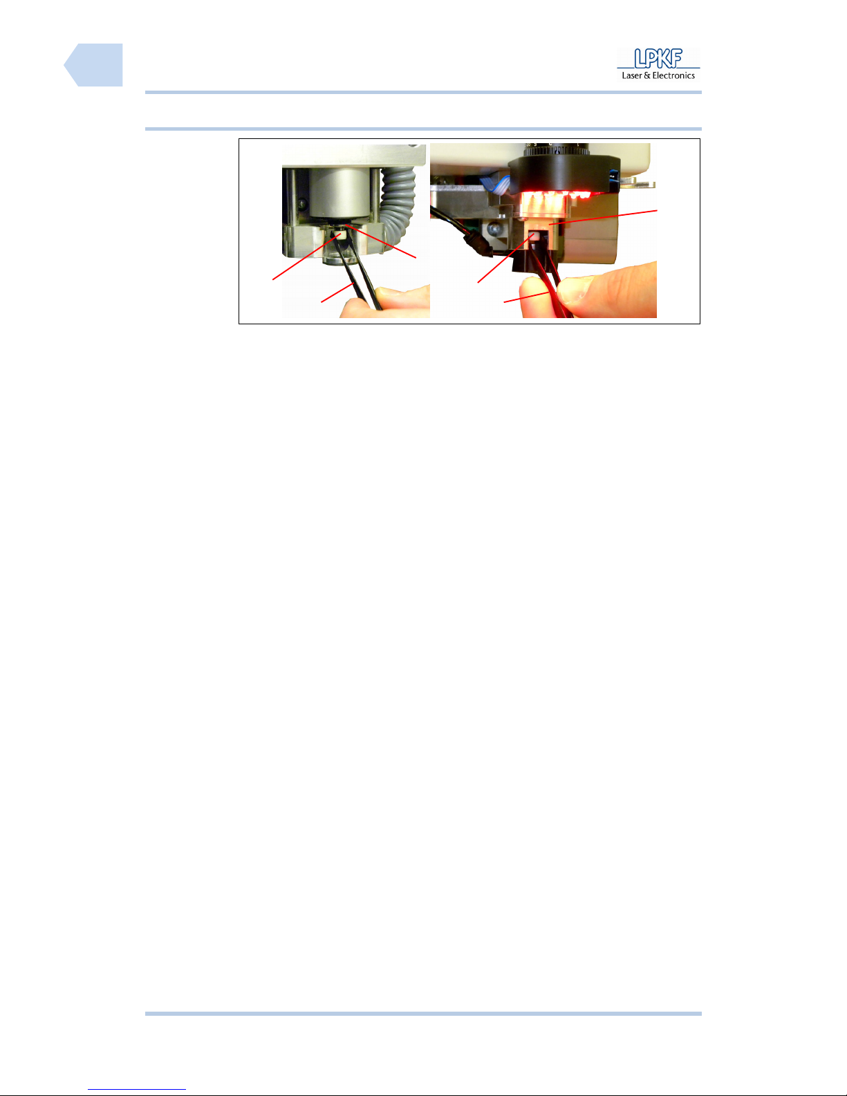
Fig. 16: Dummy
tool automatically
or mechanic lock
/1/ Dummy tool /3/ Tool holder
/2/ Tweezers
■ System start up
1. Take a tweezers and clamp the dummy tool.
2. For machines with mechanically lock:
- Turn the adjustment screw of the collet chuck.
For machines with automatic lock:
- The software open the collet chuck automatically.
➨ The tool holder release the dummy tool.
3. Remove the dummy tool.
♦ Now the circuit board plotter is ready for operation.
1
2
3
1
3
2
Page 49

ProtoMat S Operation
© 2011 LPKF AG HB V0.9/Mrz-11 47
6
Pos: 19 /ED_Technische_Dokumentation/2_Bedienungsa nleitung/Maschi ne/RP_Fräsbohrplot ter/ProtoMat_S_Ser ie/ProtoMat_S_Ser ie_IIG/Kapite l_6_Bedienung/6_01_Be arbeitungsprozes s @ 0\mod_12549013503 49_2058.docx @ 3672 @ 12
6 Operation
The following chapter describes production processes that you can carry out
with the circuit board plotter.
CircuitPro basic knowledge is required.
6.1 Production process
The production process has always three phases:
Phase I System start
The circuit board plotter, the PC and the dust extraction have to
be activated and the control software CircuitPro has to be
started.
Phase II Execute the production mode
Corresponding to the requirements for production of the material
the machining mode, e.g. manual drilling, manual milling or
automatically operation has to be selected. During automatically
mode the individual production phases are selected manually
and will be executed by the circuit board plotter.
Phase III System shut down
The control software CircuitPro has to be terminated and the
circuit board plotter, the PC and the dust extraction must
switched off.
Page 50
Operation ProtoMat S
48 HB V0.9/Mrz-11 © 2011 LPKF AG
6
Pos: 20 /ED_Technische_Dokumentation/2_Bedienungsa nleitung/Maschi ne/RP_Fräsbohrplot ter/ProtoMat_S_Ser ie/ProtoMat_S_Ser ie_IIG/Kapite l_6_Bedienung/6_02_0 1_System_starten @ 0\mod_1254904224405_2 058.docx @ 3675 @ 23
6.2 Start system
Always proceed in the same sequence when starting the system.
Note
The dust extraction is connected to the circuit board plotter
via a control cable and is operating automatically. The dust
extraction will be activated and deactivated by the circuit
board plotter.
■ System start
1. Check all connection cables and tubes.
➨ Exchange damaged cables or tubes at once.
2. Open the soundproof hood of the soundproof housing.
3. Switch on the circuit board plotter by setting the main switch to position 1
(ON).
4. Start the PC by setting the main switch to position 1 (ON).
5. Enter user name and password. Wait until the operation system has
booted the user interface.
6. Go to the task bar and click on Start>Programs>LPKF Laser &
Electronics>CircuitPro.
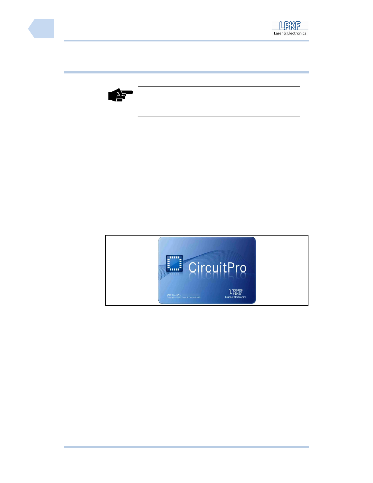
➨ The CircuitPro start-up logo is shown:
Fig. 17: Startup
image
♦ CircuitPro starts and establish the connection to the circuit board plotter.
Page 51
ProtoMat S Operation
© 2011 LPKF AG HB V0.9/Mrz-11 49
6
6.2.1 Tool status monitoring
Note
Only printed board plotter with automatically tool exchange
support this function.
It is possible that the mill/drill head is equipped with a tool, used by a production
process in the past. This tool can eject or must placed in the tool holder.
CircuitPro is checking the tool status.
■ Eject tool
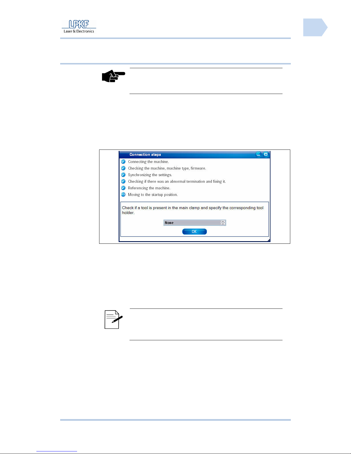
➨ When the connected circuit board plotter is detected by CircuitPro the
following message is shown:
Fig. 18: Check
active tool
1. Click {None} if no tool is clamped into the collet chuck.
or
1. Click {Tool From Tool Holder ID} and edit the tool position into the
input field \Tool Holder ID\.
2. Click on [Ok].
➨ The tool is placed in the tool holder according to the edit tool position.
Note
The drill/mill head moves to the zero position, if the value “0“
is entered in the input field \Tool holder ID\. The message
“Open collet chuck“ is shown. Click [OK] to eject the tool.
♦ The tool is placed in the tool holder.
Page 52
Operation ProtoMat S
50 HB V0.9/Mrz-11 © 2011 LPKF AG
6
Pos: 21 /ED_Technische_Dokumentation/2_Bedienungsa nleitung/Maschi ne/RP_Fräsbohrplot ter/ProtoMat_S_Ser ie/ProtoMat_S_Ser ie_IIG/Kapite l_6_Bedienung/6_02_0 2_Bedienoberf läche_CircuitPro @ 0\ mod_1267182074217_2058. docx @ 6460 @ 344
6.2.2 Grafical user interface
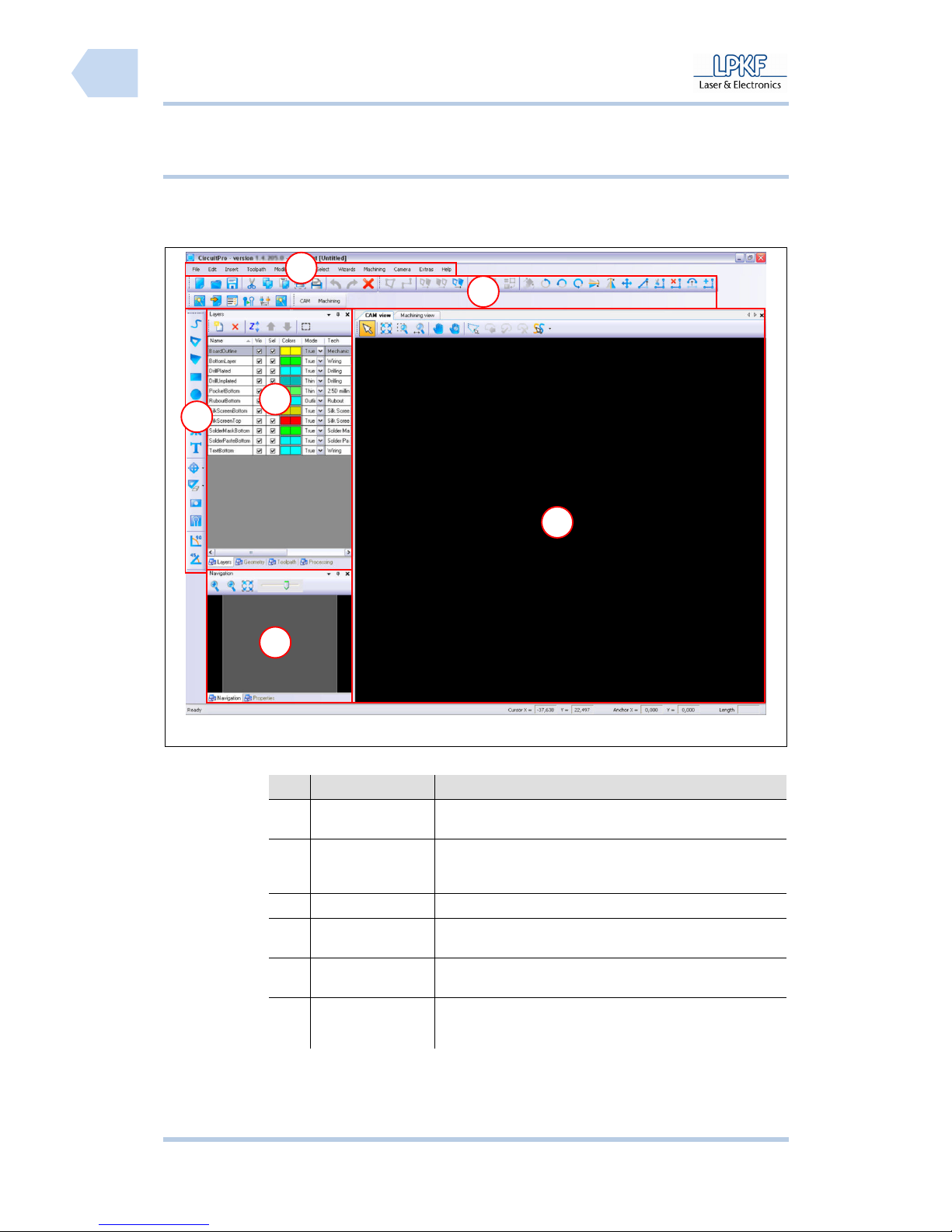
The CircuitPro user interface consists of several windows.
Fig. 19: User
interface
Tab. 9: User
interface
Nr. Display Function
/1/ Menu bar The individual program menus can be accessed via the
menu bar.
/2/ Function bar The function bar contains several functions for the control
of the circuit board plotter and modification of the
machining process.
/3/ Window Layer The window “Layer” lists the individual project layers.
/4/ Function bar
Insert
The function bar “Insert” contains several objects
which can be inserted into the project data.
/5/ Window
Navigation
The window “Navigation“ displays the actual
working area.
/6/ CAM View
The window “CAM View“ shows the project data.
The individual objects are highlighted in user
defined colours.
5
1
2
6
3
4
Page 53
ProtoMat S Operation
© 2011 LPKF AG HB V0.9/Mrz-11 51
6
6.2.2.1 Menu bar
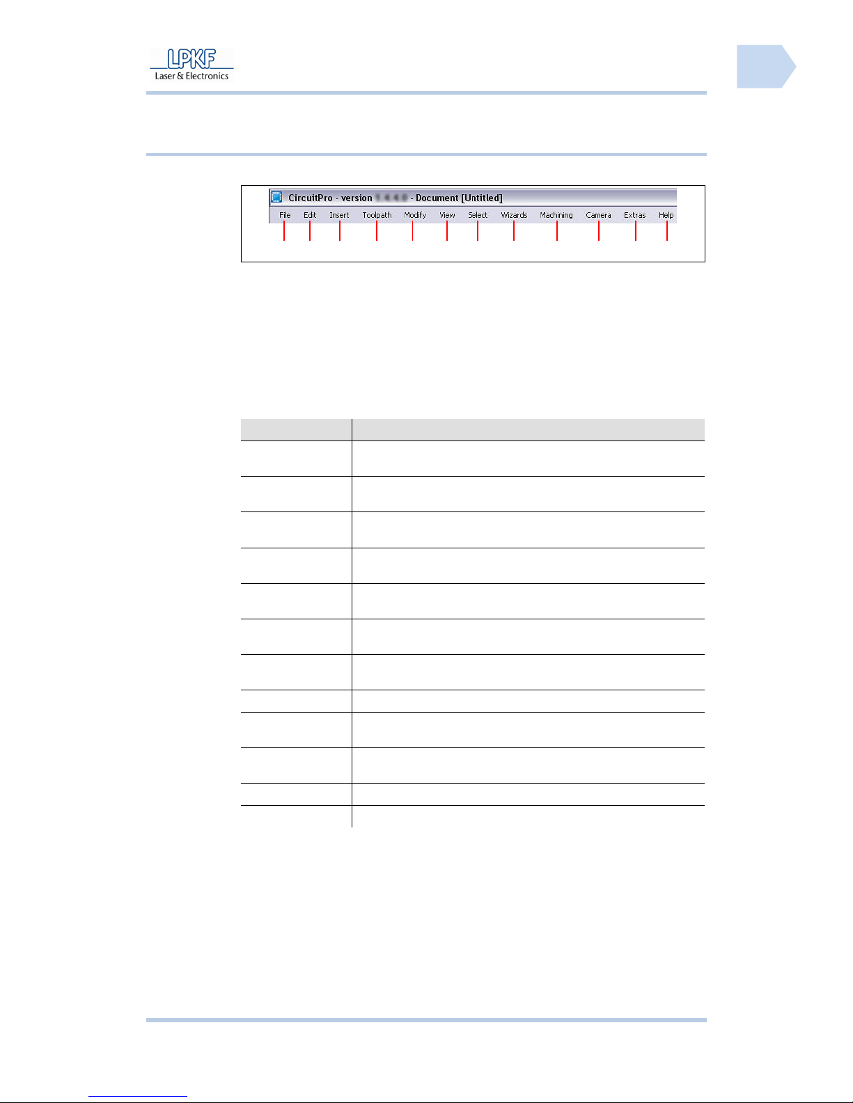
The CircuitPro program functions can be accessed via the menu bar.
Fig. 20: Menu bar
/1/ Menu File /7/ Menu Select
/2/ Menu Edit /8/ Menu Wizards
/3/ Menu Insert /9/ Menu Machining
/4/ Menu Toolpath /10/ Menu Camera
/5/ Menu Modify /11/ Menu Extras
/6/ Menu View /12/ Menu Help
Tab. 10: Menus
Menu Short description
File The menu “File“ provides program functions to open, store,
import and export work files.
Edit The menu “Edit“ provides program functions to create work data
as well as files, e.g. placing of new objects on the base material.
Insert The menu “Insert“ provides program functions to insert tool
paths or work areas.
Toolpath The menu “Toolpath“ includes the functions isolate tool path and
process contours.
Modify The menu “Modify“ offers program functions to process tool
paths.
View The menu “View“ allows the operator to activate/deactivate the
possible program windows.
Select Use the functions of the menu “Select“ to select certain zones of
the working area.
Wizards The menu “Wizards” is using to open several wizards.
Machining Use the functions of the menu “Operate“ to control the
machining process.
Camera The menu “Camera” offers program functions to set the installed
camera.
Extras The menu “Extras” offers functions to customize CircuitPro.
Help The menu “Help“ gives information about this program.
1 2 3 4 5 6
7
8 9 10
11
12
Page 54
Operation ProtoMat S
52 HB V0.9/Mrz-11 © 2011 LPKF AG
6
6.2.2.2 Function bar
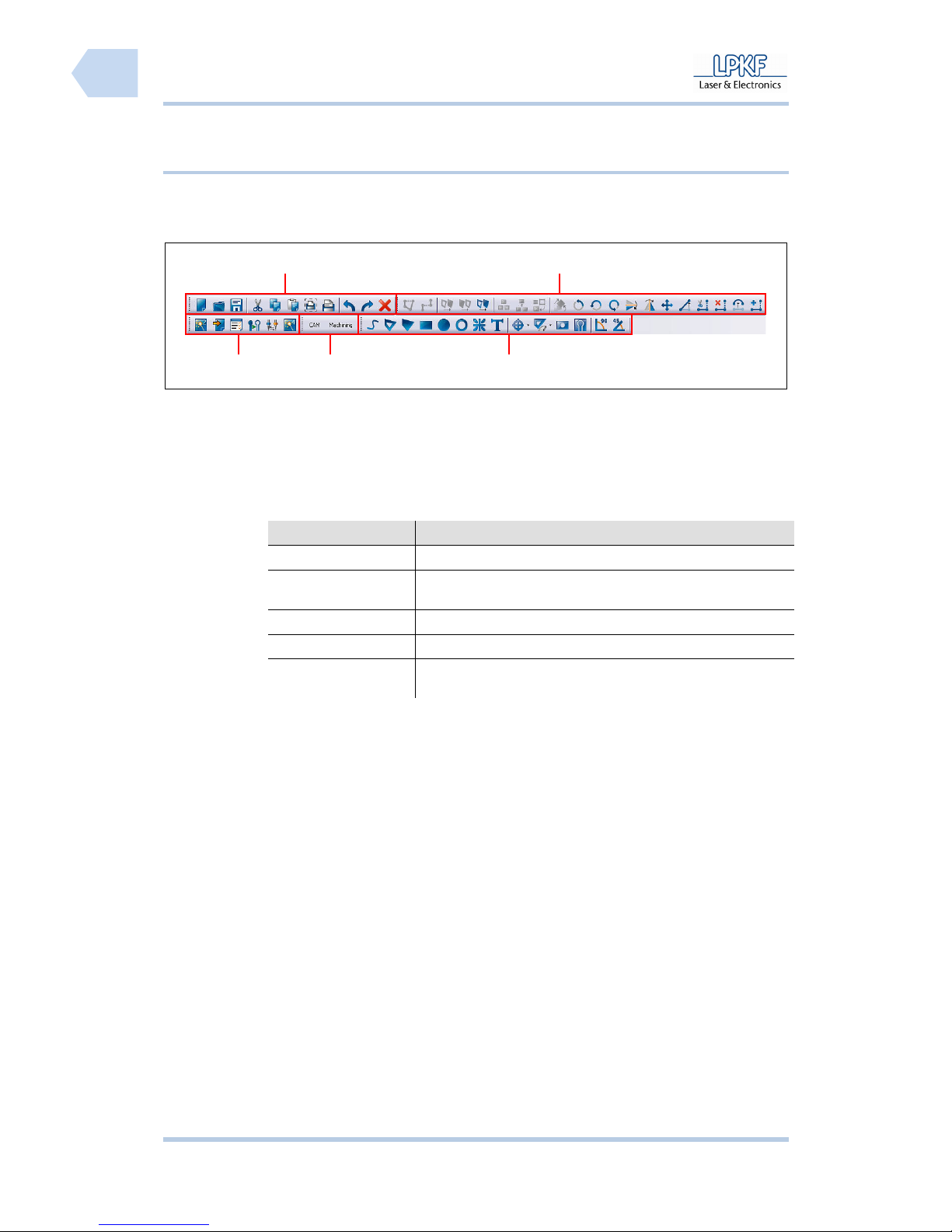
Tab. 11: Function
bars
Function Description
Processing Starts the wizards and opens several tool change functions.
Layouts Change the main window. The user can switch over from
CAM view to machining view.
Insert Several object functions.
Edit Several tool path functions.
Standard General program functions e.g. Open, Save, Import/Export
and Print.
Fig. 21: Function
bar
/1/ Processing /4/ Edit
/2/ Layouts /5/ Standard
/3/ Insert
1
4
2
3
5
Page 55
ProtoMat S Operation
© 2011 LPKF AG HB V0.9/Mrz-11 53
6
Pos: 22 /ED_Technische_Dokumentation/2_Bedienungsa nleitung/Maschi ne/RP_Fräsbohrplot ter/ProtoMat_S_Ser ie/ProtoMat_S_Ser ie_IIG/Kapite l_6_Bedienung/6_02_0 3_Fenster_Proc essing @ 0\mod_126719668 9265_2058.docx @ 6498 @ 34444 44
6.2.3 Window Processing
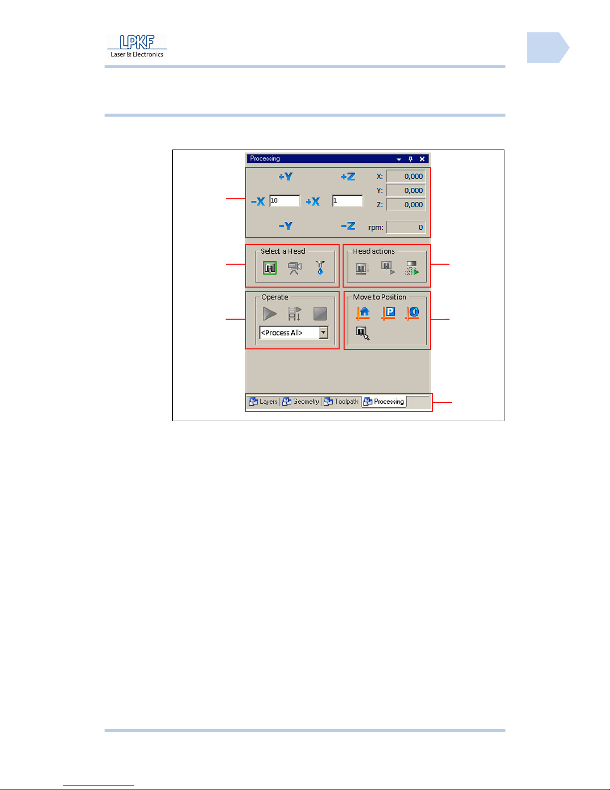
The connected circuit board plotter is controlled via the menu window
“Processing“:
Fig. 22: Window
Processing
/1/ Mill/drill head manual control functions /4/ Register
/2/ Select head /5/ Moving to determined positions
/3/ Processing functions /6/ Mill/drill head control
6
5
4
3
2
1
Page 56
Operation ProtoMat S
54 HB V0.9/Mrz-11 © 2011 LPKF AG
6
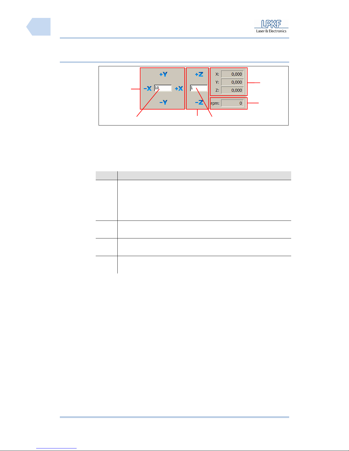
6.2.3.1 Manual control of the mill/drill head
Fig. 23: Control of
mill/drill head
/1/ Manual control X/Y direction /4/ Input field \Z step range\
/2/ Input field \X/Y step range\ /5/ Display motor speed
/3/ Manual control Z direction /6/ Display X/Y/Z coordinates
The individual buttons have the following functions:
No. Description
/1/, /2/ Type a value into the entry box \X/Y step size\ and click [-X] to move
the mill/drill head to the left side or click [+X] to move the mill/drill head
to the right side.
Type a value into the input field \X/Y step size\ and click [-Y] to move
the mill/drill head forward or click [+Y] to move the mill/drill backward.
/3/, /4/ Type a value into the input field \X/Y step size\ and click [-Z] to lift
down the mill/drill head or click [+Z] to lift up the mill/drill head.
/5/ The output field \R:\ displays the current spindle rotation speed of the
mill/drill head.
/6/ The output fields \X:\, \Y:\ and \Z:\ show the current position of the
mill/drill head.
6
1
4
5
32
Page 57
ProtoMat S Operation
© 2011 LPKF AG HB V0.9/Mrz-11 55
6
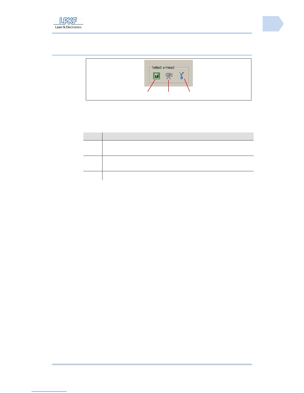
6.2.3.2 Select head
Fig. 24: Select
head
/1/ Mill/drill head /3/ Dispenser
/2/ Camera
The individual buttons have the following functions:
No. Description
/1/ Click [Mill/drill head] to move the mill/drill head (with mounted tool) to
the current camera position.
/2/ Click [Camera] to move the mill/drill head (with camera) to the current
tool position.
/3/ Click [Dispenser] to move the mill/drill head (with Dispenser) to
2 1
3
Page 58
Operation ProtoMat S
56 HB V0.9/Mrz-11 © 2011 LPKF AG
6
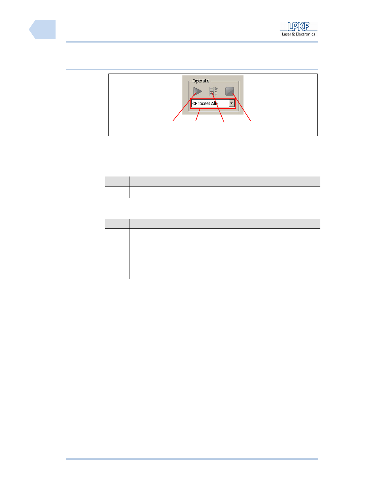
6.2.3.3 Operate
Fig. 25: Operate
/1/ Start processing /3/ Start processing select area
/2/ Selection field \Phase\ /4/ Stop processing
The input field has the following function:
No. Description
/2/ Click the selection field \Phase\ and select a machining phase.
The individual buttons have the following functions:
No. Description
/1/ Click [Start processing] to start the complete machining process.
/3/ Select a machining phase and mark the machining area with the
mouse. Click [Start processing select area] to start processing of the
machining phase within the selected area.
/4/ Click [Stop processing] to stop the current machining process.
4
3
2
1
Page 59
ProtoMat S Operation
© 2011 LPKF AG HB V0.9/Mrz-11 57
6
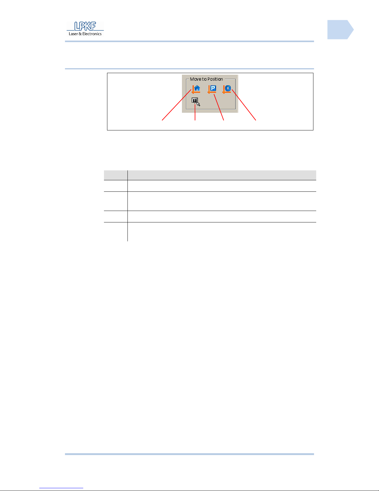
6.2.3.4 Move to Position
Fig. 26: Move to
Position
/1/ Home position /3/ Pause position
/2/ Move by mouse position /4/ Zero position
The individual buttons have the following functions:
No. Description
/1/ Click [Home Position] to move the mill/drill head to the home position.
/2/ Click [Move by mouse position] and the mill/drill head follows the
current mouse position.
/3/ Click [Pause Position] to move the mill/drill head to the pause position.
/4/ Click [Zero Position] to move the mill/drill head to the zero position
(reference point).
4 3
2
1
Page 60
Operation ProtoMat S
58 HB V0.9/Mrz-11 © 2011 LPKF AG
6
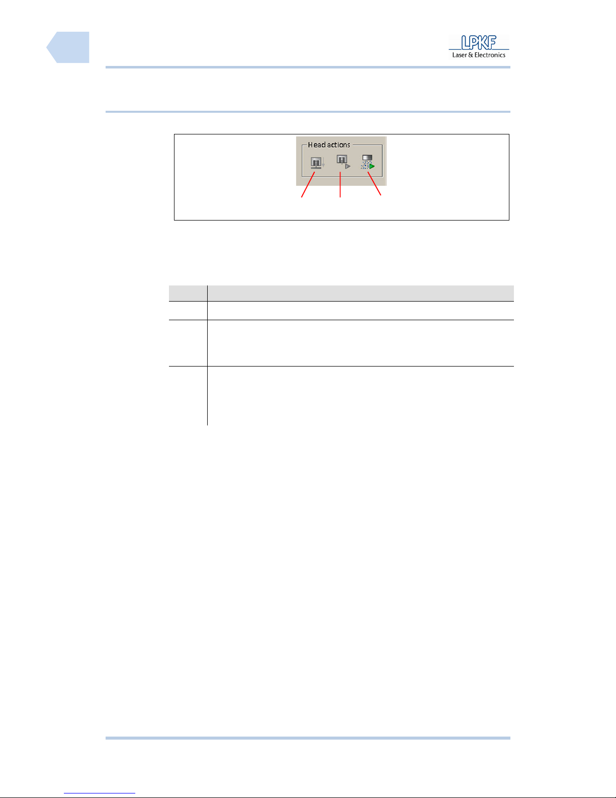
6.2.3.5 Head actions
Fig. 27: Various
/1/ Lift mill/drill head up/down /3/ Exhaust unit on/off
/2/ Motor on/off
The individual buttons have the following functions:
No. Description
/1/ Click [Lift head up/down] to lower the mill/drill head.
/2/ Click [Motor on/off] to start or stop the motor.
The symbol changes correspondingly from a green triangle (90°
position) to a red rectangle.
/3/ Click [Exhaust unit on/off] to activate/deactivate the exhaust unit by
operator.
The symbol changes correspondingly from a green triangle (90°
position) to a red rectangle.
3
2
1
Page 61
ProtoMat S Operation
© 2011 LPKF AG HB V0.9/Mrz-11 59
6
Pos: 23 /ED_Technische_Dokumentation/2_Bedienungsa nleitung/Maschi ne/RP_Fräsbohrplot ter/ProtoMat_S_Ser ie/ProtoMat_S_Ser ie_IIG/Kapite l_6_Bedienung/6_03_ Maschine_verbind en @ 0\mod_1267453299757_ 2058.docx @ 6550 @ 2
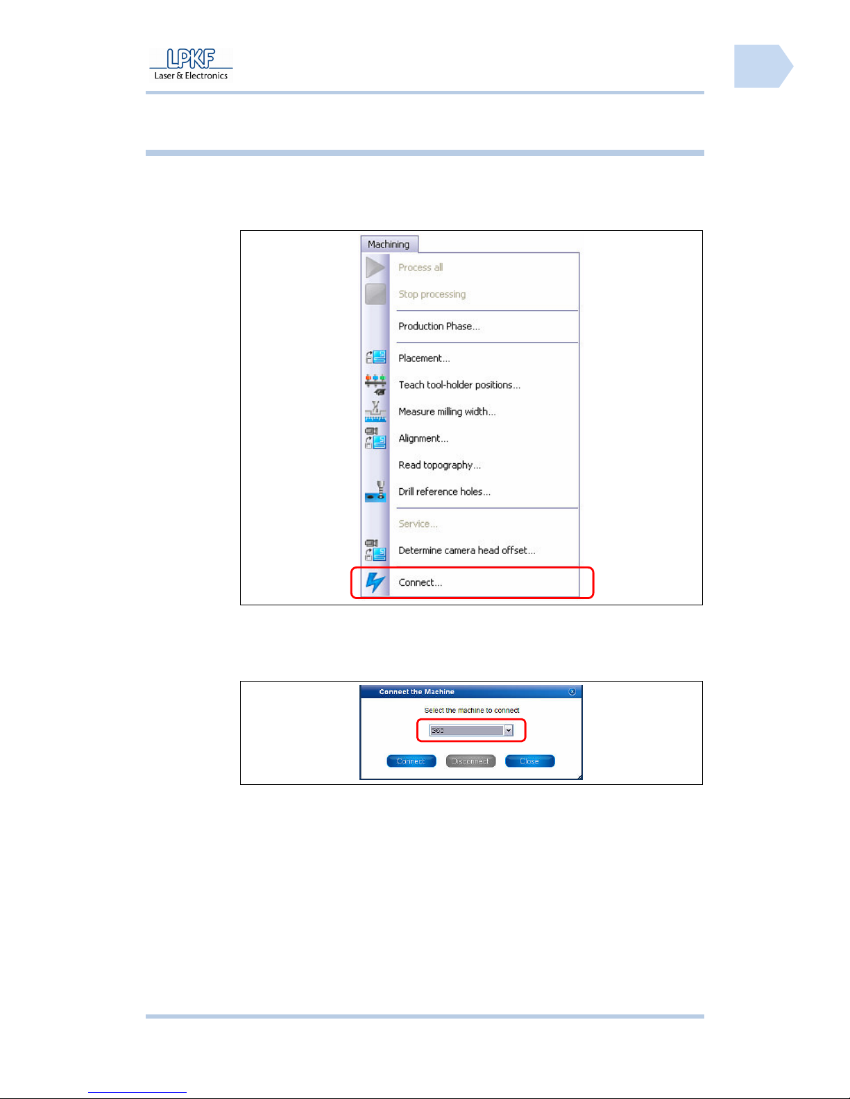
6.3 Establish a connection
As a first step a connection between the PC and the circuit board plotter has to
be established.
■ Establish a connection
Fig. 28: Select
circuit board
plotter
1. Go to the menu “Machining“ and click “Connect…”.
➨ The following window is shown:
Fig. 29: Connect
2. Click on the selection box \Machine type\ and select the type of the
connected machine.
3. Click [Connect].
Page 62
Operation ProtoMat S
60 HB V0.9/Mrz-11 © 2011 LPKF AG
6
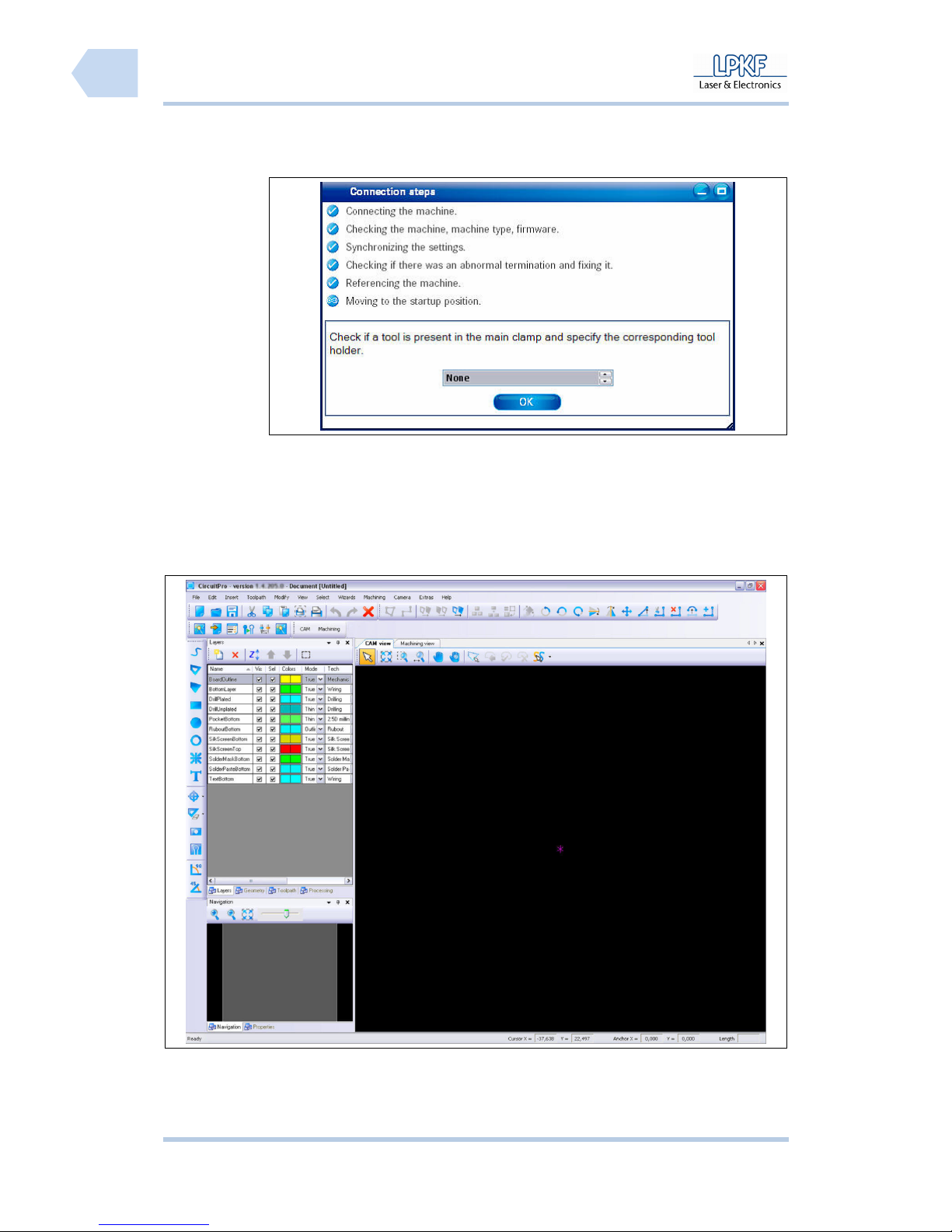
➨ The connection to the circuit board plotter is established and the following
message appears:
Fig. 30:
Connection
➨ After the circuit board plotter was detected and its data will be transmitted,
the CircuitPro user interface opens:
Fig. 31: User
interface
♦ Now the circuit board plotter is ready for operation.
Pos: 24 /ED_Technische_Dokumentation/2_Bedienungsa nleitung/Maschi ne/RP_Fräsbohrplot ter/ProtoMat_S_Ser ie/ProtoMat_S_Ser ie_IIG/Kapite l_6_Bedienung/6_04_ Material_auflege n @ 0\mod_1255676413949_2 058.docx @ 3960 @ 2
Page 63
ProtoMat S Operation
© 2011 LPKF AG HB V0.9/Mrz-11 61
6
6.4 Place material
Before any machining process the material has to be placed and fixed on the
working table.
■ Apply material
Fig. 32: Control
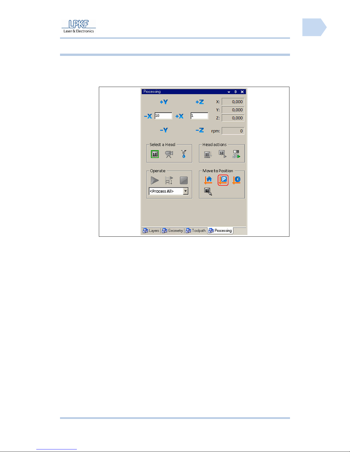
1. Click on [Move to pause position].
➨ The mill/drill head moves to pause position.
2. Open the soundproof hood.
3. Clean the working table and remove material rest with a smooth paint
brush or a slightly damp cloth.
4. Place the underlay on the working table so that the pivots fit into the
reference holes.
5. Place the production material on the underlay in a way that the pivots fit
into the reference holes.
6. Check the production material. The head of the reference hole pivots
must be lower than the production material surface.
For machines without vacuum table:
7. Fix the production material with a tape on the underlay. The tape has to
be removable without remains. The tape has to be guided alongside the
edges.
♦ The production material is fixed.
Pos: 25 /ED_Technische_Dokumentation/2_Bedienungsa nleitung/Maschi ne/RP_Fräsbohrplot ter/ProtoMat_S_Ser ie/ProtoMat_S_Ser ie_IIG/Kapite l_6_Bedienung/6_05_W erkzeug_einri chten @ 0\mod_12556765048 14_2058.docx @ 3964 @ 23
Page 64
Operation ProtoMat S
62 HB V0.9/Mrz-11 © 2011 LPKF AG
6
6.5 Tool setup
Note
Any change of tools is performed manually for circuit board
plotters without tool exchange appliance.
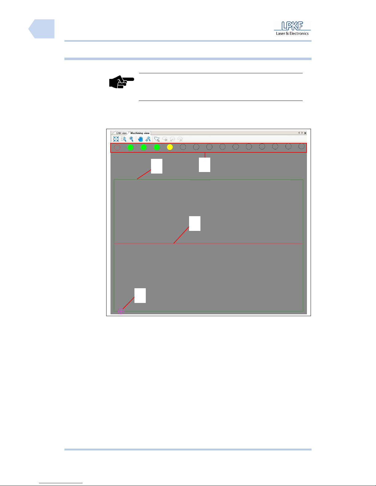
The tool magazine of the circuit board plotter can house up to 15 different tools.
The position of each tool is displayed in the window “Machining view“.
Fig. 33:
Machining view
/1/ Tool position /3/ Axis of refexion
/2/ Machining area /4/ Current mill/drill head position
1
2
3
4
Page 65
ProtoMat S Operation
© 2011 LPKF AG HB V0.9/Mrz-11 63
6
■ Tool setup
1. Insert a new tool into a free position of the tool exchange appliance.
Fig. 34: Tool
exchange
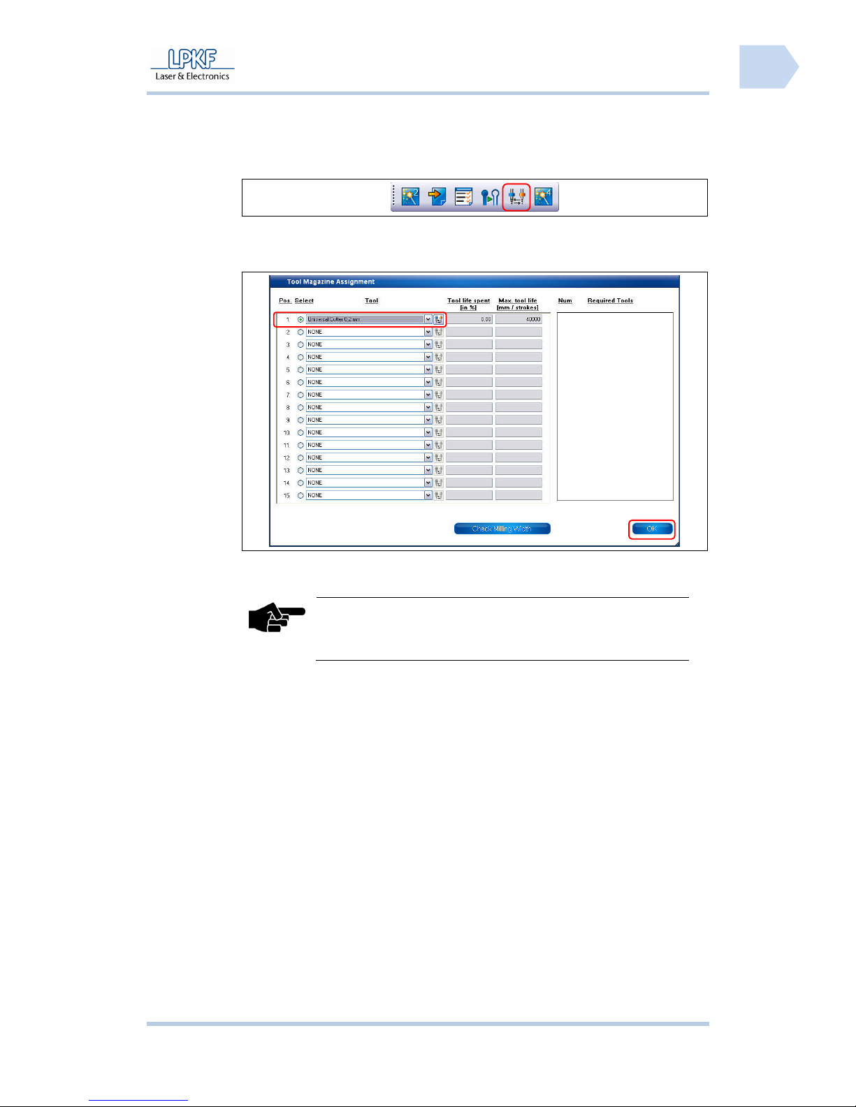
2. Click [Change tool].
➨ The following window is displayed:
Fig. 35: Tool
setup
3. Select a free position of the entry field \Tools\ and specify the tool.
Note
A selection of supported tools can be found in the list
“required tools“.
4. Click [Apply].
♦ Now the tool is configured.
Page 66
Operation ProtoMat S
64 HB V0.9/Mrz-11 © 2011 LPKF AG
6
6.5.1 Tool colour code
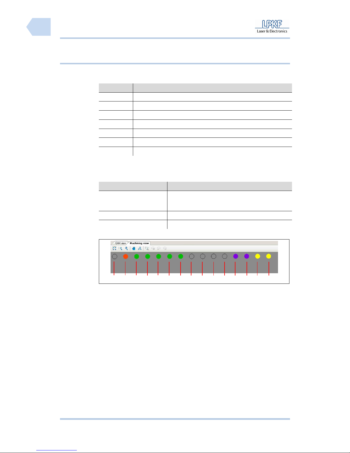
All LPKF tools are equipped with a distance ring, colour coded accordingly to
the tool applications:
Tab. 12: Tool
colour coding
Colour Tool application
Red MicroCutter
Orange UniversalCutter
Blue EndMill (RF)
Purple EndMill
Olive-green EndMill (long)
Yellow ContourRouter
Green SpiralDrills
The tool position display of the window “machining view” is corresponding to the
colour coding definitions:
Tab. 13: Tool
position display
code
Display Definition
Filled coloured circle The tool position is equipped with a mill or drill tool. The
displayed colour is according to the tool application
(see Tab. 12: Tool colour coding)
Unfilled coloured circle The tool is removed.
Unfilled black circle The tool position is not equipped.
Example:
Fig. 36: Tool
holder
/1/ not assembled /9/ not assembled
/2/ MicroCutter /10/ not assembled
/3/ SpiralDrill /11/ not assembled
/4/ SpiralDrill /12/ EndMill
/5/ SpiralDrill /13/ EndMill
/6/ SpiralDrill /14/ ContourRouter
/7/ SprialDrill /15/ ContourRouter
/8/ not assembled
1 2 3 4 5 6 7 8 9 10 11 12 13 14 15
Page 67
ProtoMat S Operation
© 2011 LPKF AG HB V0.9/Mrz-11 65
6
Pos: 26 /ED_Technische_Dokumentation/2_Bedienungsa nleitung/Maschi ne/RP_Fräsbohrplot ter/ProtoMat_S_Ser ie/ProtoMat_S_Ser ie_IIG/Kapite l_6_Bedienung/6_06_ Manuelles_Bohren @ 0\ mod_1254904262916_205 8.docx @ 3679 @ 2
6.6 Manual drilling
Note
Every individual tool for the PCB production must be clamped into
the mill/drill head manually, if a circuit board plotter without
automatic tool change function is used.
For the process “manual drilling“ the corresponding drill is inserted into the
collet chuck of the mill/drill head and the drilling position will be reached via
mouse movement. The motor is activated/deactivated by a clicking the start
button as well.
Note
The tools available allow drilling of round holes with a max.
diameter of 3 mm.
ATTENTION
Health hazard!
During machining process of work pieces harmful fine particles
and gases may occur which can be inhaled!
Make sure that the dust extraction is activated during machining
of the work piece. Be sure to use fine particle filters exclusively.
ATTENTION
Risk of injury!
During the machining process the used tools and the collet
chuck heat up, direct contact may cause burnings.
Wear protective gloves and tweezers for manual change of tools
during operation.
ATTENTION
Risk of injury!
The used tools are sharp-edged and cause cut or stab wounds
when used improperly.
Store the tools always in the toolbox and secure the toolbox
against unauthorised utilisation.
Page 68
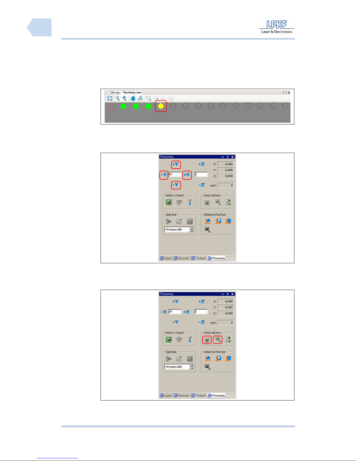
Operation ProtoMat S
66 HB V0.9/Mrz-11 © 2011 LPKF AG
6
■ Produce a drill hole
1. The preparative activities are described in detail on page 61.
➨ The PCB material is fixed on the working table.
Fig. 37:
Machining view
select tool
2. Select a drilling tool.
3. Move the mill/drill head to the start position:
Fig. 38: Adjust
position
Type a value into the input filed \X/Y step size\ and click[+X], [-X], [+Y] or
[-Y] until the drilling position is reached.
The exact position is displayed in the output fields \X:\ and \Y:\.
Fig. 39: Control
milling/drilling
head
4. Click on [motor on/off].
Page 69

ProtoMat S Operation
© 2011 LPKF AG HB V0.9/Mrz-11 67
6
➨ The drilling spindle rotates and the dust extraction is activated.
5. Click on [Lift head up/down ].
➨ The mill/drill head is lowered and the corresponding drilling hole is created.
After this process the mill/drill head returns to the rest position.
6. Click on [Motor on/off].
➨ The drilling spindle stops and the dust extraction is deactivated.
7. Repeat steps 3 to 6 if you wish to create further drilling holes.
♦ The drilling hole is created.
Page 70
Operation ProtoMat S
68 HB V0.9/Mrz-11 © 2011 LPKF AG
6
Pos: 27 /ED_Technische_Dokumentation/2_Bedienungsa nleitung/Maschi ne/RP_Fräsbohrplot ter/ProtoMat_S_Ser ie/ProtoMat_S_Ser ie_IIG/Kapite l_6_Bedienung/6_07_ Manuelles_Fräsen @ 0\ mod_1254904431585_20 58.docx @ 3687 @ 2
6.7 Manual milling
Note
Every individual tool for the PCB production must be clamped into
the mill/drill head manually, if a circuit board plotter without
automatic tool change function is used.
For the process “manual milling“ the milling tool has to be inserted into the collet
chucks of the mill/drill head. The mill/drill head will be moved to start position
and then the motor is to be started. Afterwards the mill/drill head is lift down and
the milling track will be accessed. The milling depth is adjusted automatically.
The production result depends directly on the depth of penetration of the used
milling tool. An insufficient material removal between the PCB tracks may cause
malfunctions of the printed circuit board. For the conical milling tools like
UniversalCutter and MicroCutter the milling depth is determinate by the depth of
penetration of the milling tool.
Always mill a test track on the PCB material and check the milling depth using a
measuring microscope. Change the milling depth setting if required and repeat
the milling process until you have the result required.
Note
Using the milling depth limiter depth of penetration can be
exactly adjusted to the required result in 2-µm steps.
ATTENTION
Health hazard!
During machining process of work pieces harmful fine particles
and gases may occur which can be inhaled!
Make sure that the dust extraction is activated during machining
of the work piece. Be sure to use fine particle filters exclusively.
ATTENTION
Risk of injury!
During the machining process the used tools and the collet
chuck heat up, direct contact may cause burnings.
Wear protective gloves and tweezers for manual change of
tools during operation.
Page 71

ProtoMat S Operation
© 2011 LPKF AG HB V0.9/Mrz-11 69
6
ATTENTION
Risk of injury!
The used tools are sharp-edged and cause cut or stab wounds
when used improperly.
Store the tools always in the toolbox and secure the toolbox
against unauthorised utilisation.
Page 72
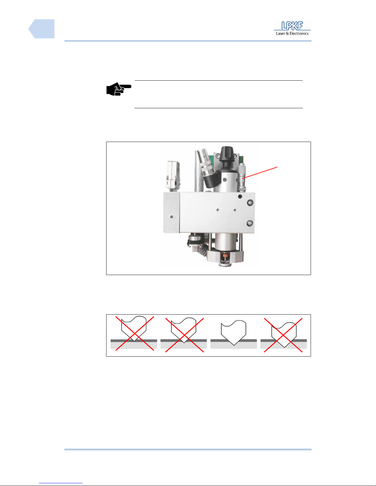
Operation ProtoMat S
70 HB V0.9/Mrz-11 © 2011 LPKF AG
6
■ Manual setting of milling depth
Note
Only for circuit board plotters with manual setting of the milling
depth the milling depth has to be adjusted using a micrometer
screw.
1. Preparative activities are described in detail on page 61.
➨ The PCB material is fixed on the working table.
Fig. 40: Mill/drill
head
2. Adjust the milling depth with the micrometer screw /1/.
3. Produce a test track.
4. Check the result using a measuring microscope.
Fig. 41: Optimal
milling depth
5. Repeat the process in necessary until a sufficient amount of material has
been removed.
♦ The milling depth is now adjusted.
1
Page 73
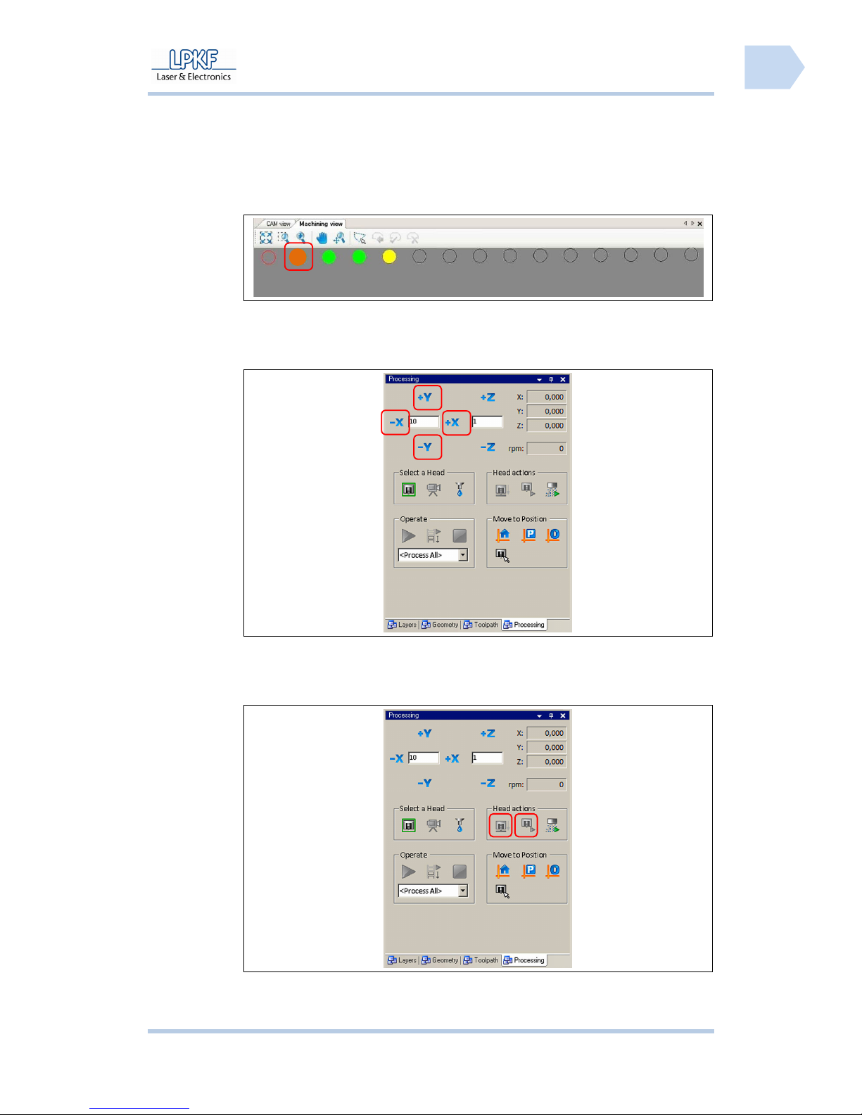
ProtoMat S Operation
© 2011 LPKF AG HB V0.9/Mrz-11 71
6
■ Produce a milling track
1. Preparative activities are described in detail on page 61
➨ The PCB material is fixed on the working table.
Fig. 42:
Machining view
select tool
2. Select a milling tool.
3. Move the mill/drill head to start position:
Fig. 43: Set
position
Click[+X], [-X], [+Y] or [-Y] until the start position is reached.
The exact position is displayed in the output field \X:\ and \Y:\.
Fig. 44:
Milling/drilling
head control
4. Click on [Motor on/off].
Page 74

Operation ProtoMat S
72 HB V0.9/Mrz-11 © 2011 LPKF AG
6
➨ The drilling spindle rotates and the dust extraction is activated.
5. Click on [Lift head up/down ].
➨The mill/drill head is lowered according to the milling depth setting.
6. Click [+X], [-X], [+Y] or [-Y] until the final position is reached.
➨ Now the milling track is produced.
7. Click on [Lift up/down head].
➨ The mill/drill head will be lift up.
8. Click on [Motor on/off].
➨ The drilling spindle stops and the dust extraction will be deactivated.
9. For further milling tracks you have to repeat the steps 3 to 8.
♦ Now the milling path is produced.
Page 75
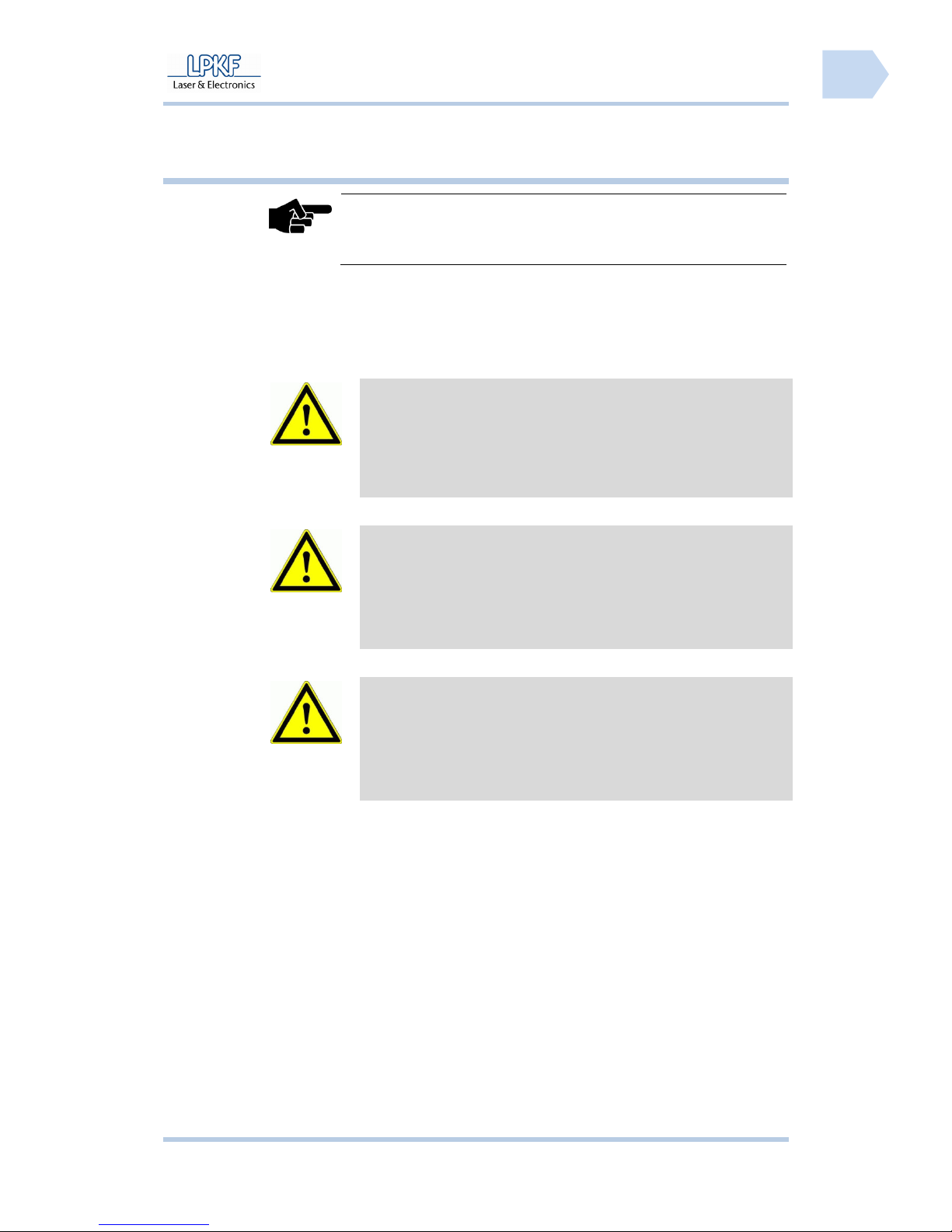
ProtoMat S Operation
© 2011 LPKF AG HB V0.9/Mrz-11 73
6
Pos: 28 /ED_Technische_Dokumentation/2_Bedienungsa nleitung/Maschi ne/RP_Fräsbohrplot ter/ProtoMat_S_Ser ie/ProtoMat_S_Ser ie_IIG/Kapite l_6_Bedienung/6_08_Au tomatikbetrieb @ 0\ mod_1254904474284_205 8.docx @ 3691 @ 233343
6.8 Automatic mode
Note
Every individual tool for the PCB production must be clamped into
the mill/drill head manually, if a circuit board plotter without
automatic tool change function is used.
During automatic operation single or multilayer PCBs are produced semiautomatically. According to the prepared CBF file the tools are selected and the
drill holes and milling paths are produced.
ATTENTION
Health hazard!
During machining of work pieces harmful fine particles and
gases may occur which can be inhaled!
Make sure that the dust extraction is activated during machining
of the work piece. Be sure to use fine particle filters exclusively.
ATTENTION
Risk of injury!
During the machining process the used tools and the collet
chuck heat up, direct contact may cause burnings.
Wear protective gloves and tweezers for manual change of tools
during operation.
ATTENTION
Risk of injury!
The used tools are sharp-edged and cause cut or stab wounds
when used improperly.
Store the tools always in the toolbox and secure the toolbox
against unauthorised utilisation.
Page 76
Operation ProtoMat S
74 HB V0.9/Mrz-11 © 2011 LPKF AG
6
6.8.1 Specify production type
Production data is assembled using the “Process Planning Wizard“.
■ Generate production data
Fig. 45: Start
wizard
1. Click Wizards>Process planning wizard….
➨ The following window is shown:
Fig. 46: Process
planning wizard
2. Edit the required setting for the production process and click [Next].
3. Follow the instructions of the assistant.
Page 77
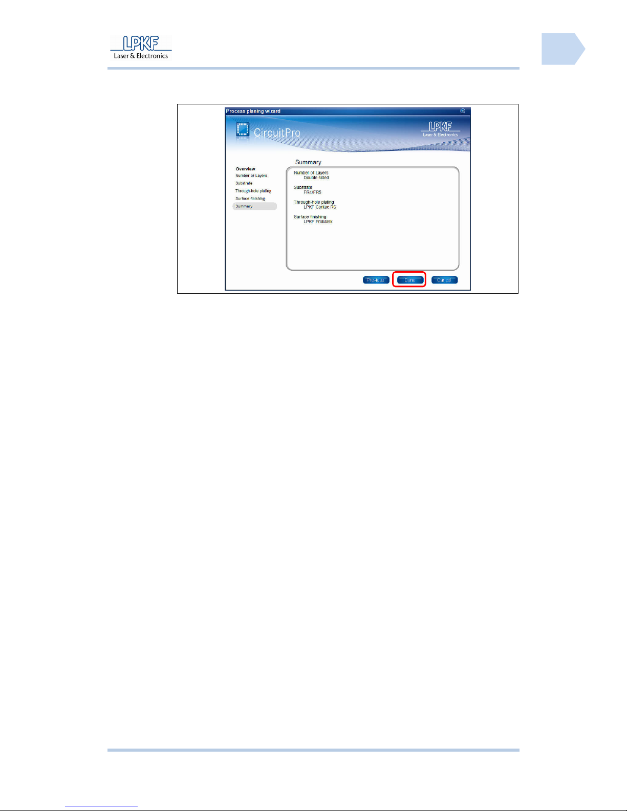
ProtoMat S Operation
© 2011 LPKF AG HB V0.9/Mrz-11 75
6
➨ If all settings have been made the following window is shown:
Fig. 47: Summary
4. Click [Done] and the window will be closed.
♦ Now the production process is configured.
Page 78
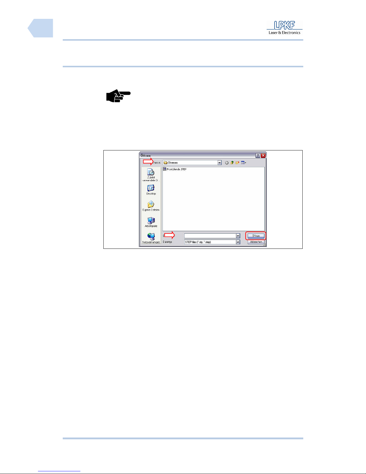
Operation ProtoMat S
76 HB V0.9/Mrz-11 © 2011 LPKF AG
6
6.8.2 Loading the CBF file
A CBF file contains all data required for the production of printed circuit boards.
You can either open an existing CBF file to rework it or create a new file.
Note
CircuitPro processes always one CBF file. Whenever you
open a additional file, all data is overwritten.
■ Open a CBF file
1. Click File>Open.
➨ The window “Open” is shown:
Fig. 48: Window
Open
2. Click the selection field \Search in:\ and select a destination folder.
3. Click on the CBF file.
➨ The file name appears in the selection field \File name\.
4. Click [Open].
➨ The CBF file is loaded and the projects contained are placed on the working
area.
Page 79
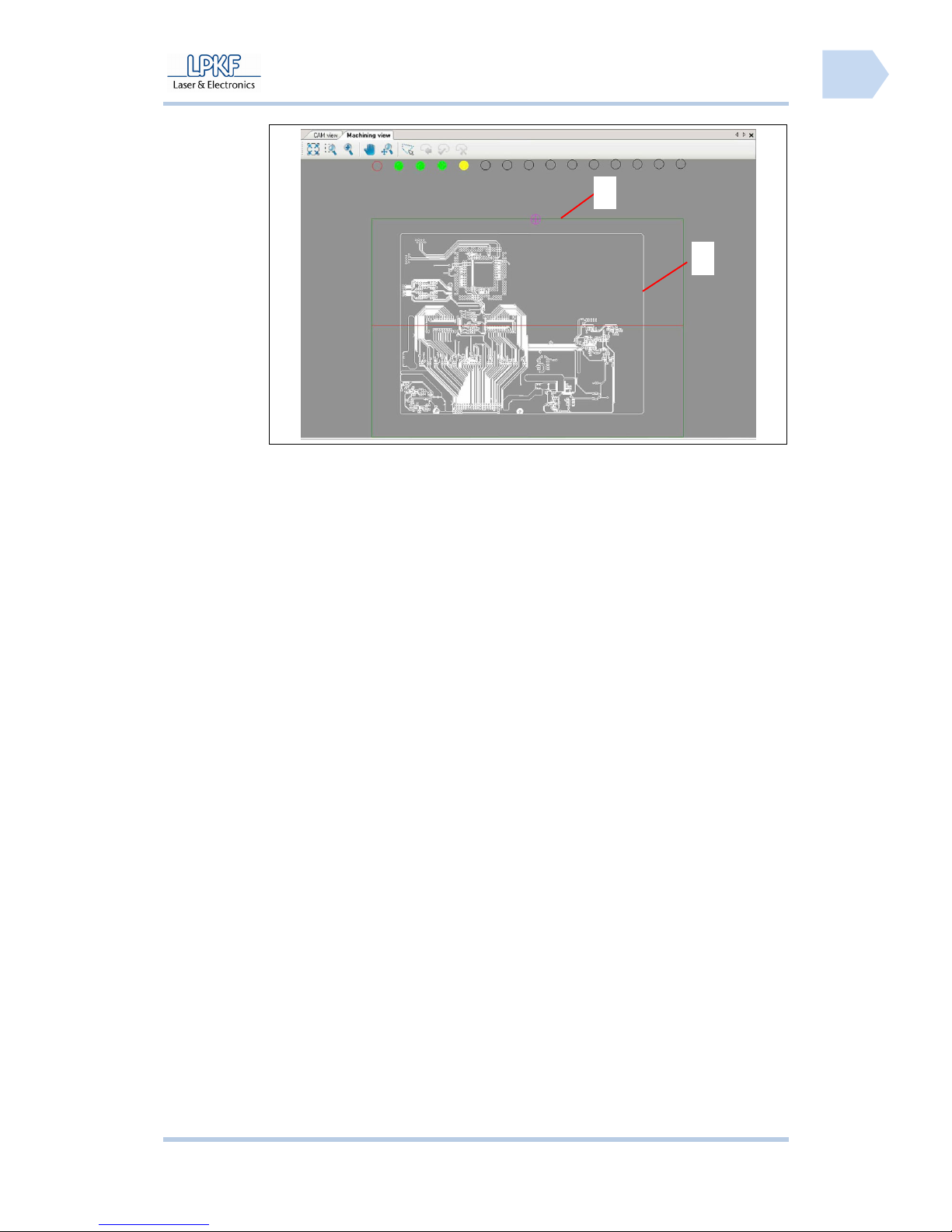
ProtoMat S Operation
© 2011 LPKF AG HB V0.9/Mrz-11 77
6
Fig. 49: Working
area
/1/ Working area /2/ PCB data
♦ Now the CBF file is loaded.
1
2
Page 80
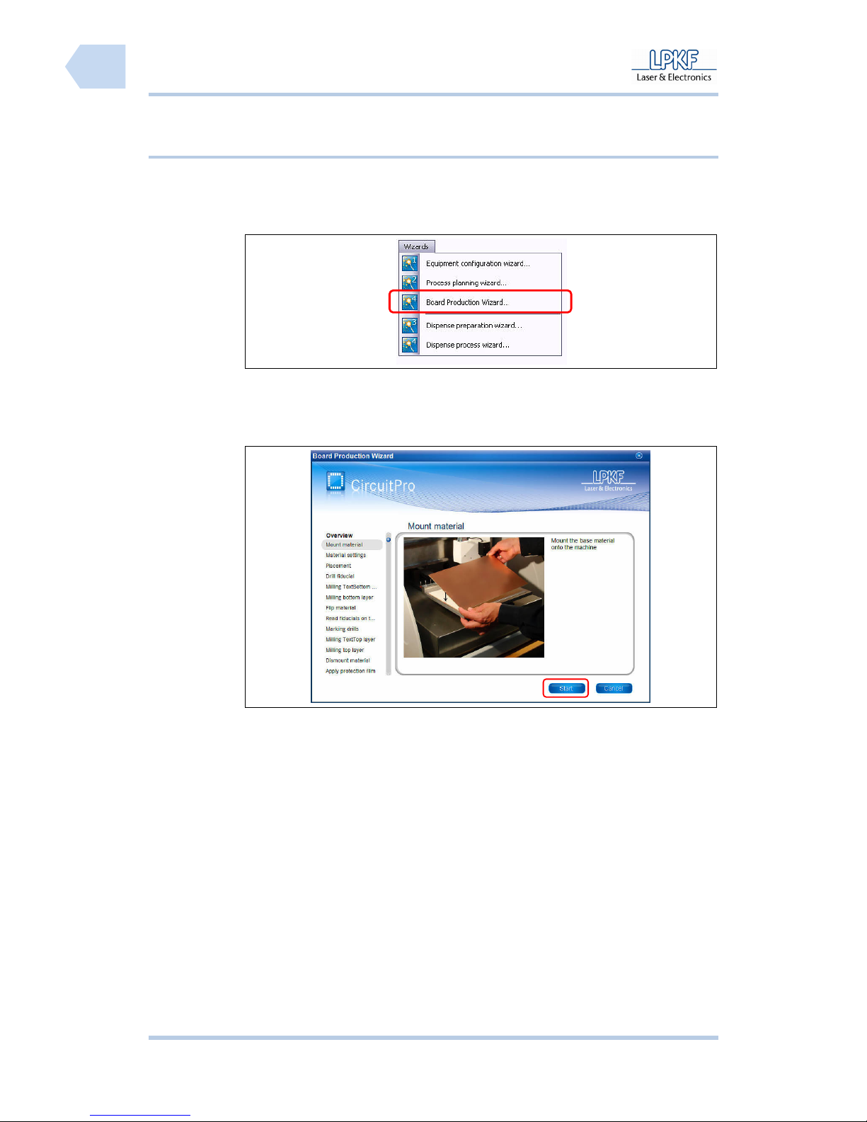
Operation ProtoMat S
78 HB V0.9/Mrz-11 © 2011 LPKF AG
6
6.8.2.1 Production of the printed circuit board
The production process can start when all settings for the PCB production have
are entered completely.
■ Production process
Fig. 50: Start
wizard
1. Click Wizard>Board Production Wizard.
➨ The following window is shown:
Fig. 51: Process
planning wizard
2. Follow the instructions and click [Start].
➨ The next production step is shown.
3. Follow the instructions and click [Next].
Page 81
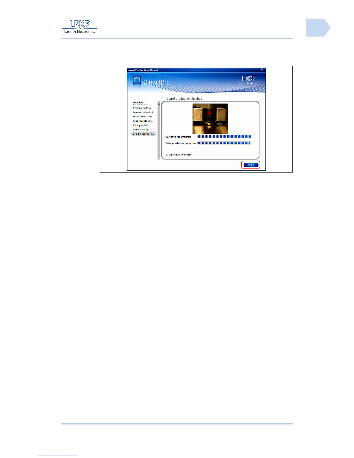
ProtoMat S Operation
© 2011 LPKF AG HB V0.9/Mrz-11 79
6
➨ The PCB production is finished, when all productions steps a run through and
the following window is shown:
Fig. 52: Process
planning wizard
4. Click [Finish] to stop the board production process.
5. Demount the board.
6. Clean the board and make a visual check.
♦ The board production is finished.
Page 82
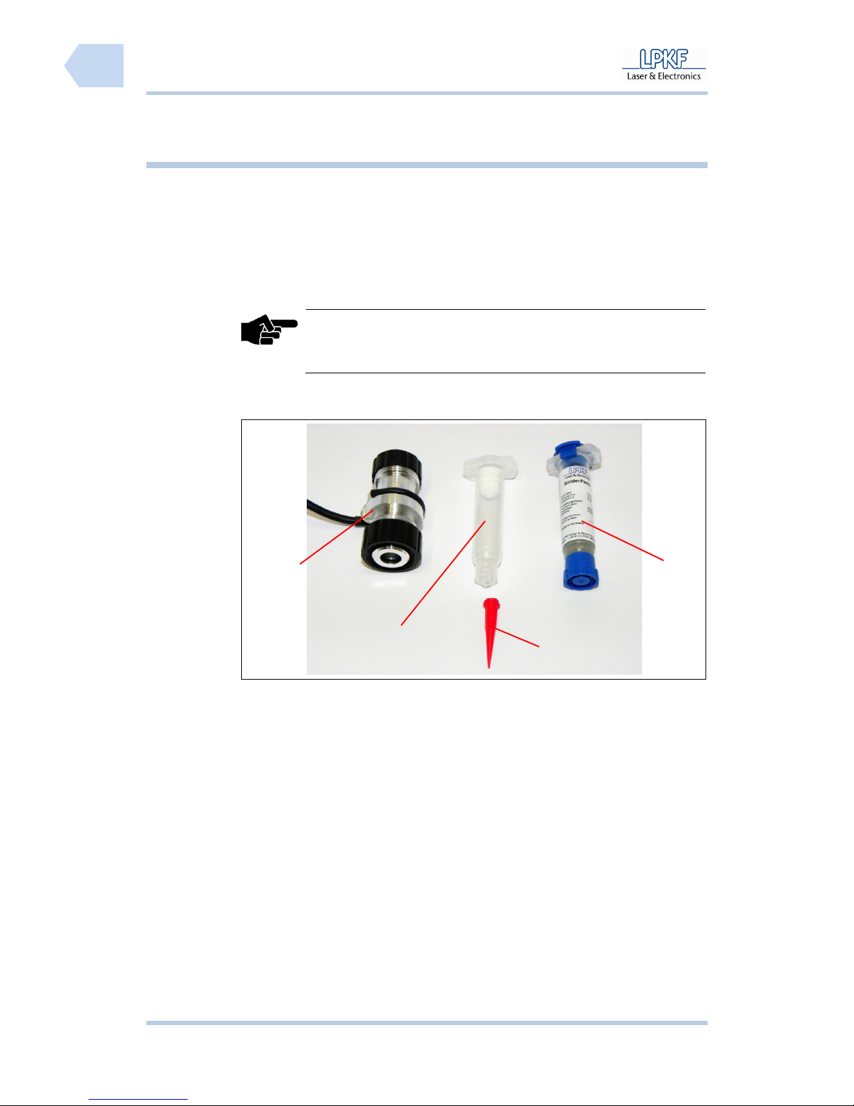
Operation ProtoMat S
80 HB V0.9/Mrz-11 © 2011 LPKF AG
6
Pos: 29 /ED_Technische_Dokumentation/2_Bedienungsa nleitung/Maschi ne/RP_Fräsbohrplot ter/ProtoMat_S_Ser ie/ProtoMat_S_Ser ie_IIG/Kapite l_6_Bedienung/6_09_Di spensen @ 0\mod_1296650 538439_2058.doc x @ 13793 @ 233
6.9 Dispense
The dispense device is used to apply solder paste on the printed circuit board
before the placement of SMD parts starts. With compressed air the solder paste
will be applied point by point with precision and in small quantity. Also applying
SMD glue or other materials which can be filled into cartridges is called
dispensing.
Note
The dispensing device is included in the delivery for all mill/drill
plotters with automatic tool change function.
The dispense set consists of:
Fig. 53: Complete
dispense set
/1/ Dispense adapter /3/ Dispensing tip
/2/ Empty cartridge /4/ Solder Paste cartridge
A plastic hose to connect the dispense device to the compressed air system is
also included in the delivery.
1
2
3
4
Page 83
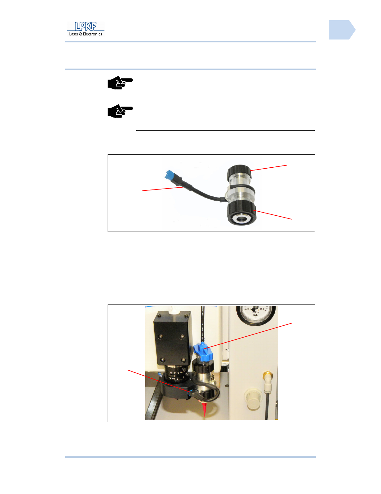
ProtoMat S Operation
© 2011 LPKF AG HB V0.9/Mrz-11 81
6
6.9.1 Mount dispense set
Note
Keep the solder paste stored in a cool place until consumption.
Before starting the dispense process the solder paste must be
warmed up to room temperature.
Note
The installation of the dispense set will be guided by an intuitive
wizard. Start the installation of the dispense set when requested
by the wizard.
■ Assembling the dispense set
Fig. 54: Dispense
adapter
1. Take the dispense adapter and loosen the upper fastening nut /3/. Pull
out the empty cartridge.
2. Take the empty cartridge and unscrew the dispensing tip.
3. Take the solder paste cartridge and unscrew the lower end cap. Screw
the dispensing tip on the outlet opening of the solder paste cartridge.
4. Insert the solder paste cartridge into the dispense adapter and tighten the
upper fastening nut carefully.
Fig. 55: Installed
dispense set
1
2
3
1
3
Page 84
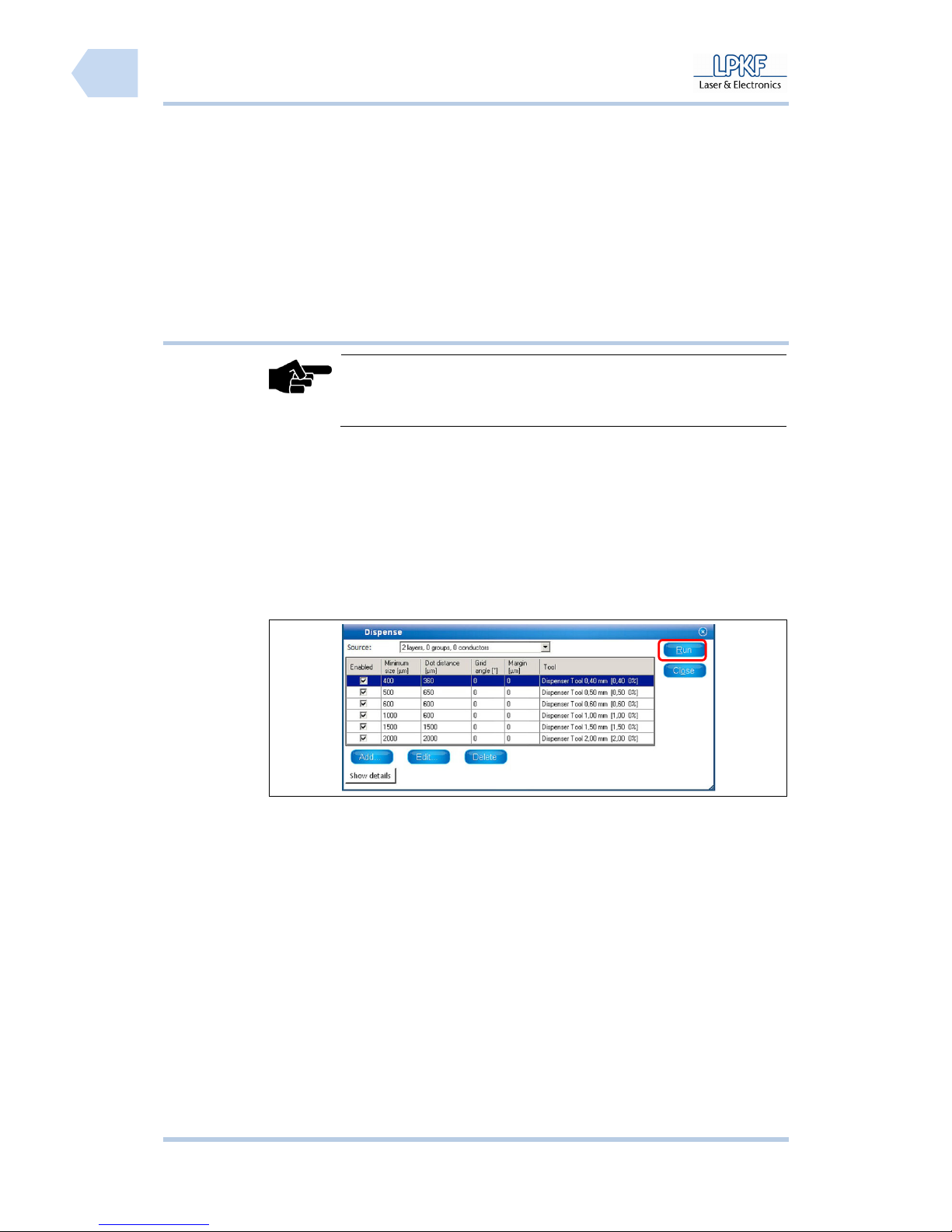
Operation ProtoMat S
82 HB V0.9/Mrz-11 © 2011 LPKF AG
6
5. Remove the upper closure cap of the solder paste cartridge and plug in
the coupling of the plastic hose /3/. Turn the coupling to fix it on the
solder paste cartridge.
6. Loosen the lower fastening nut and plug the dispense adapter into the
fixing device on the right side of the mill/drill head.
7. Plug the dispense adapter connection cable into the jack on the camera
lighting system /1/.
♦ The dispense device is ready to operate.
6.9.2 Dispense process
Note
A production file with the prepared solder paste layer must be
created before the dispense process can start.
■ Dispense process
1. Click on File>Open to open the project file.
➨ The project file will be loaded and the project data is displayed in the window
“CAM view”.
2. Click on Toolpath>Dispense.
➨ The following window is shown:
Fig. 56: Window
Dispense
3. Use the default values or enter new dispense parameters for the current
project.
4. Click [Run].
➨ The program is assigning the solder paste points.
5. Click on Wizards>Dispense preparation wizard.
Page 85
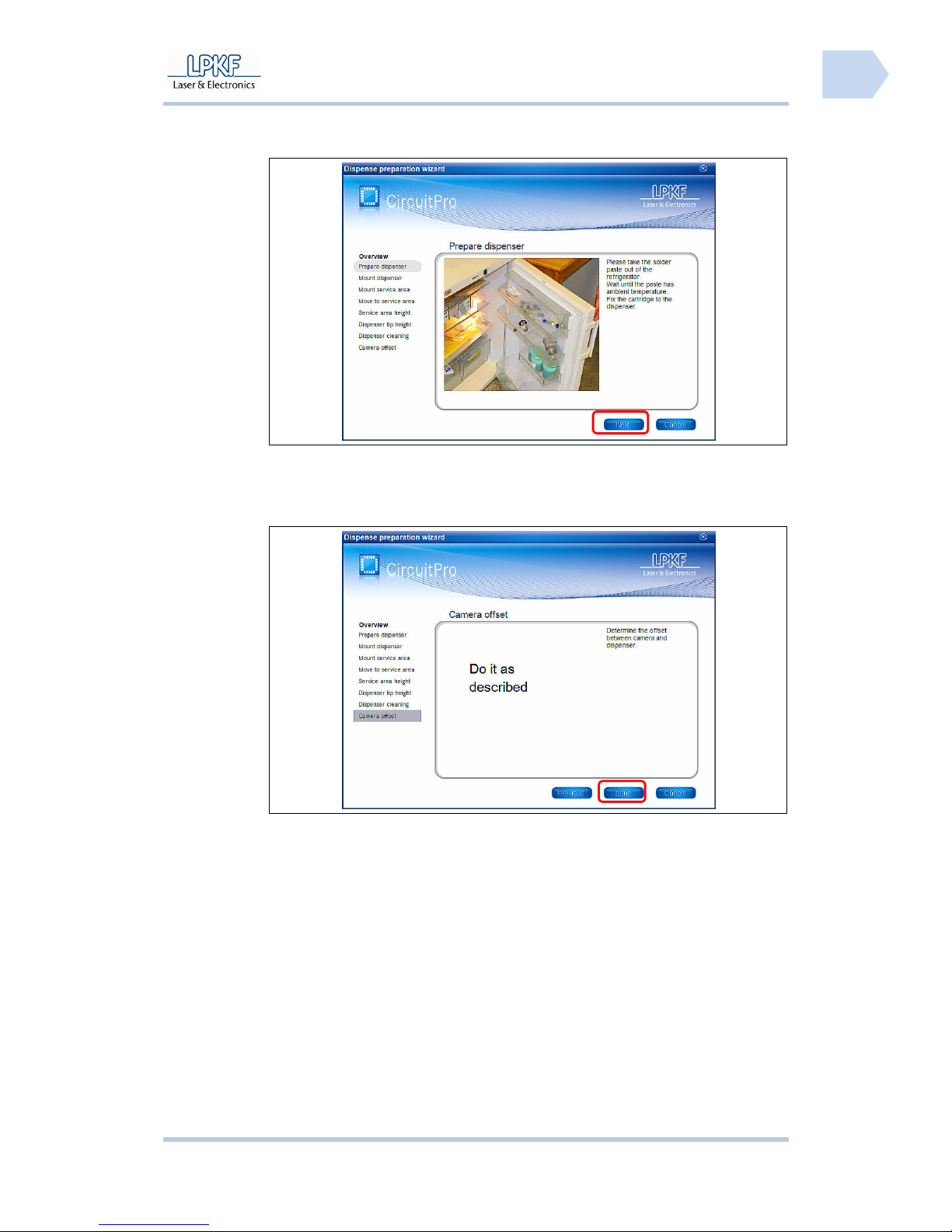
ProtoMat S Operation
© 2011 LPKF AG HB V0.9/Mrz-11 83
6
➨ The wizard is starting and the following window is shown:
Fig. 57: Start
Dispense
preparation
wizard
6. Follow the instructions and click [Next].
➨ After all processing steps have been carried out the following window is
shown:
Fig. 58: Dispense
preparation
wizard finished
7. Click [Done].
➨
The dispense preparation is finished.
8. Click on Wizards>Dispensing wizard.
➨ The wizard is starting and the following window is shown:
Page 86
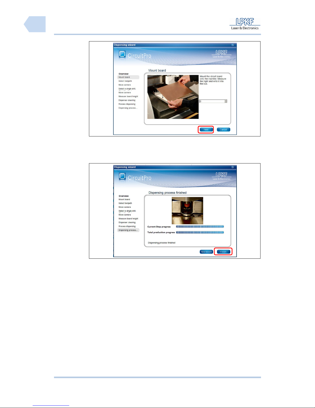
Operation ProtoMat S
84 HB V0.9/Mrz-11 © 2011 LPKF AG
6
Fig. 59: Start
Dispensing
wizard
9. Follow the instructions and click [Next].
➨ After all processing steps have been carried out the following window is
shown:
Fig. 60:
Dispensing
wizard finished
10. Click [Finish].
♦ The dispensing process is finished.
Page 87
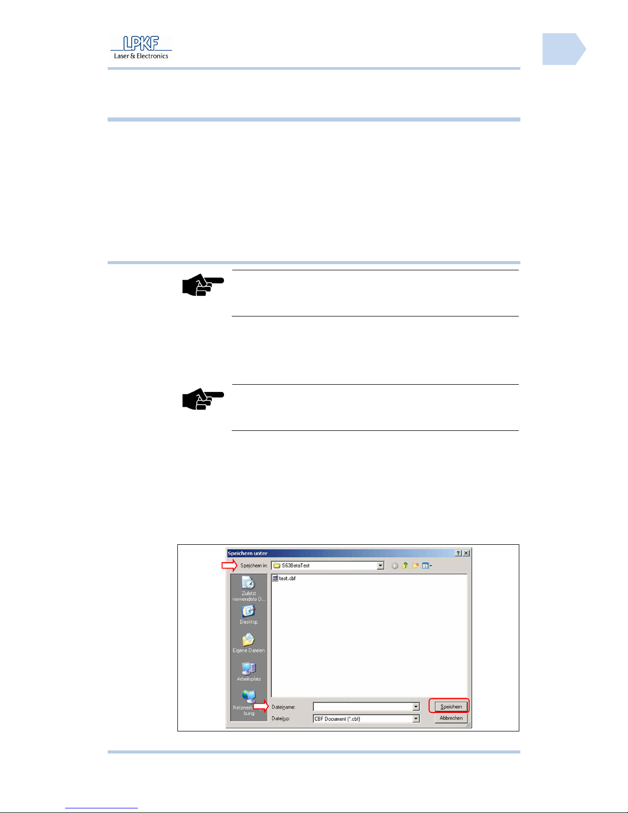
ProtoMat S Operation
© 2011 LPKF AG HB V0.9/Mrz-11 85
6
Pos: 30 /ED_Technische_Dokumentation/2_Bedienungsa nleitung/Maschi ne/RP_Fräsbohrplot ter/ProtoMat_S_Ser ie/ProtoMat_S_Ser ie_IIG/Kapite l_6_Bedienung/6_10_Sy stem_ausschalt en @ 0\mod_1254904321722_ 2058.docx @ 3683 @ 233343
6.10 Shutdown the System
Always proceed in the same sequence when shutdown the system:
I Save the current CBF file
II Exit CircuitPro
III Switch off the circuit board plotter
IV Shutdown and switch off the PC
V Switch off the dust extraction
6.10.1 Saving the CBF file
Note
Always save the current production data.
It is possible to save the current production data under the same file name or
under a new file name as well.
■ Saving the CBF file
Note
All existing data will be overwritten!
1. Click File>Save.
♦ The production data was saved by using the current file name.
■ Saving a new CBF file
1. Click File>Save as….
➨ The window “Save as…” is shown:
Fig. 61: Save as…
Page 88
Operation ProtoMat S
86 HB V0.9/Mrz-11 © 2011 LPKF AG
6
2. Click the input field \Save in\ and select the destination folder.
3. Click the input field \File name\ and edit the new file name.
4. Click [Save].
♦ The production data is saved in a new file.
6.10.2 Exit CircuitPro
When exit CircuitPro the mill/drill head and the working table are moving to the
zero position.
■ Exit CircuitPro
1. Click File>Exit.
♦ CircuitPro is terminated.
6.10.3 Switch off the circuit board plotter
Note
Always wait until the mill/drill head and the working table have
reached their reference position.
■ Switch off the circuit board plotter
1. Open the soundproof hood.
2. Set the main switch of the circuit board plotter to position 0 (OFF).
3. Close the soundproof hood.
♦The circuit board plotter is switched off.
6.10.3.1 Shutdown and switch off the PC
Note
Of course the PC can be left in action whenever the PC is used for
other applications.
■ Shutdown the PC
1. Click Start>Shut down.
2. Wait until the PC is completely shut down and set the main switch of the
PC in position OFF (0).
♦ The PC is switched off.
6.10.4 Switch off the dust extraction
Note
The dust extraction has only to be switched off if the system
operates in continuous running mode.
In automatic mode the dust extraction is switched on/off via the
circuit board plotter.
■ Switch off the dust extraction
1. Turn the main switch of the dust extraction to position OFF (0).
♦ The dust extraction is switched off.
Pos: 31 /ED_Technische_Dokumentation/2_Bedienungsa nleitung/Maschi ne/RP_Fräsbohrplot ter/ProtoMat_S_Ser ie/ProtoMat_S_Ser ie_IIG/Kapite l_7_Fehlerbeseitigu ng/7_1_Fehlerbesei tigung @ 0\mod_125484 4173282_2058.doc x @ 3660 @ 1
Page 89
ProtoMat S Troubleshooting
© 2011 LPKF AG HB V0.9/Mrz-11 87
7
7 Troubleshooting
This chapter gives some information concerning correction of small faults that
may occur during operation of the circuit board plotter.
Note
Please contact the LPKF service if the measures described in
this chapter do not provide the desired success. LPKF is not
liable for improper repairs!
Tab. 14: Trouble
shooting
Fault Cause Remedy
No connection No power supply Check the mains cable and insert the
mains plug into the socket if necessary.
Click [Connect].
Main switch of the circuit
board plotter is in position
OFF
Set the switch to position ON.
Click [Connect].
No data transmission Check the USB cable between plotter and
PC. Fix the connector plug or exchange the
USB cable.
Click [Connect].
Check the USB settings of the operating
system.
Click [Connect].
No dust extraction No power supply Check the mains cable and insert the
mains plug into the socket if necessary.
Main switch of the dust
extraction is in position OFF
Set the operation mode switch to either ON
or AUTOMATIK.
Fuse triggered
Press the Reset Button of the dust
extraction.
No data transmission Check the USB cable between circuit
board plotter and dust extraction. Fix the
connector plug or exchange the cable.
Tool uptight Position of the tool holder is
incorrect
Import the tool holder position again.
Tool was not correctly
inserted into the tool holder
Insert the tool with its top down into the tool
holder until it stops.
Tool holder soiled Clean the tool holder.
Collet chuck soiled Clean the collet chuck.
Page 90

Troubleshooting ProtoMat S
88 HB V0.9/Mrz-11 © 2011 LPKF AG
7
Page 91
ProtoMat S Maintenance/servicing
© 2011 LPKF AG HB V0.9/Mrz-11 89
8
Pos: 32 /ED_Technische_Dokumentation/2_Bedienungsa nleitung/Maschi ne/RP_Fräsbohrplot ter/ProtoMat_S_Ser ie/ProtoMat_S_Ser ie_IIG/Kapite l_8_Instandhaltun g_Wartung/8_1_Ins tandhaltung und Wartung @ 0\ mod_1254835912406_205 8.docx @ 3653 @ 12
8 Maintenance/servicing
This chapter lists the most important maintenance and servicing activities.
8.1 Regular maintenance
Regular maintenance of the circuit board plotter includes a visual inspection
before any start of operation and regular careful cleaning.
■ Visual inspection
1. Check the mains cable of the circuit board plotter, the USB cable to the
PC, the connection cable and the tube to the dust extraction.
➨ Replace damaged cables or tubes at once.
2. Check the soundproof hood for visible damages.
3. Open the hood and check the mill/drill head and the working table for
visible damages.
➨ Contact the LPKF service immediately whenever you find a damage and
make sure that the circuit board plotter is not used until the damage is
removed.
♦ The visual inspection is successfully terminated and the circuit board plotter
can be set to operation.
■ Cleaning the circuit board plotter
Note
Clean the circuit board plotter with a dry and antistatic cloth and a
paintbrush. To remove heavy soiling use a slightly damp cloth.
1. Disconnect the circuit board plotter from the mains power supply.
2. Clean the soundproof hood using a dry and antistatic cloth.
3. Open the hood and clean the working table with a paintbrush and slightly
damp cloth.
4. Close the hood after cleaning.
5. Connect the circuit board plotter to the mains power supply.
♦ Now the circuit board plotter is cleaned.
Page 92
Maintenance/servicing ProtoMat S
90 HB V0.9/Mrz-11 © 2011 LPKF AG
8
Pos: 33 /ED_Technische_Dokumentation/2_Bedienungsa nleitung/Maschi ne/RP_Fräsbohrplot ter/ProtoMat_S_Ser ie/ProtoMat_S_Ser ie_IIG/Kapite l_8_Instandhaltun g_Wartung/8_2_W artung @ 0\mod_1254838907429_2 058.docx @ 3656 @ 2
8.2 Maintenance
For proper function of the circuit board plotter maintenance activities have to be
carried out in certain intervals.
ATTENTION
Risk of injury!
Unintended starting of the motor and moving of the mill/drill
head during repairs or maintenance may cause severe injuries.
Make sure that only one person operates the machine. Protect
the machine against unauthorised usage during maintenance
and repair activities.
ATTENTION
Risk of injury!
The opened hood of the soundproof housing may shutdown and
crush finger or the whole hand.
Open the hood of the soundproof housing always up to the
latching position and protect the machine against shocks.
Tab. 15:
Maintenance and
service plan
Component Interval/Control Maintenance activity
Milling depth limiter after 100 operating
hours
cleaning
Chucks after 100 operating
hours
cleaning
Tool position Tool is not put down
correctly
Configure tool position
Dust extraction Extraction power
decreases perceptible
Exchange fine particle filter
Page 93
ProtoMat S Storage
© 2011 LPKF AG HB V0.9/Mrz-11 91
9
Pos: 34 /ED_Technische_Dokumentation/2_Bedienungsa nleitung/Maschi ne/RP_Fräsbohrplot ter/ProtoMat_S_Ser ie/ProtoMat_S_Ser ie_IIG/Kapite l_9_Lagerung/9_1_Außer _Betrieb_nehmen @ 0\ mod_1254831435051_2 058.docx @ 3650 @ 1223
9 Storage
This chapter describes the storage of the circuit board plotter.
9.1 Shutdown
Before storage set the circuit board plotter out of operation.
■ Disassembly of the circuit board plotter
1. Switch off the circuit board plotter and the dust extraction.
2. Unplug the mains cable from the electrical safety socket.
3. Remove the tube from the dust extraction.
4. Remove the connection cable from the dust extraction.
5. Remove the USB cable from the PC.
6. Open the hood and remove the mains cable.
7. Install the transport locks.
8. Place all the connection cables on the working table and close the hood.
♦ Now the circuit board plotter is disassembled.
Note
The PC and the dust extraction have to be disassembled
accordingly. The systems can be used for other machines or they
can be stored as well. The appropriate information concerning
disassembly and storage can be found in the respective operation
manuals.
9.2 Storage
Note
The circuit board plotter has to be stored in the covering box in a
cool and dry location.
ATTENTION
Risk of injury!
The machine is heavy and bulky and cannot be transported or
lifted by one person!
Lift and transport the machine always with two persons.
■ Packaging the circuit board plotter
1. Place the covering box besides the work desk.
2. Open the box cover and take the unpacking instruction.
3. Follow the unpacking instruction step by step in reverse direction.
♦ Now the circuit board plotter is packed.
Page 94
Storage ProtoMat S
92 HB V0.9/Mrz-11 © 2011 LPKF AG
9
■ Storing the circuit board plotter
1. Select an adequate location (cool and dry) for storage.
2. Place the covering box on an euro pallet.
3. Transport the euro pallet with a lift truck to the storage location.
4. Protect the covering box with a foil or a suitable tarpaulin.
♦ Now the circuit board plotter is stored.
9.2.1 Disposal
Note
Legal regulations and directives concerning disposal of electric
devices and machines have to be observed.
Dispose of the circuit board plotter must be done according to legal directives.
Page 95

ProtoMat S Appendix
© 2011 LPKF AG HB V0.9/Mrz-11 93
10
Pos: 35 /ED_Technische_Dokumentation/2_Bedienungsa nleitung/Maschi ne/RP_Fräsbohrplot ter/ProtoMat_S_Ser ie/ProtoMat_S_Ser ie_IIG/Kapite l_10_Anhang/10_1_W erkzeug und Verbrauchsm aterial @ 0\mod_1254755 787395_2058.doc x @ 3647 @ 12344344
10 Appendix
10.1 Tools and consumables
10.1.1 Tools
Any tool for the circuit board plotter can be ordered individually:
Tab. 16: Tools
Tool specification Length
(mm)
Ø
(mm)
Order
code.
End Mill RF, special tool, cylindrical, 1/8“ 36 0,15 115 832
End Mill RF, special tool, cylindrical, 1/8“ 36 0,25 115 833
End Mill RF, special tool, cylindrical, 1/8“ 36 0,40 115 834
Universal Cutter, conical, 1/8“ 36 0,2/0,5 115 835
Micro Cutter, Fine Line, conical, 1/8“ 36 0,1/0,15 115 836
End Mill long, cylindrical, PCB/aluminium 1/8“ 38 1,00 115 837
End Mill long, cylindrical, PCB/aluminium 1/8“ 38 2,00 115 838
End Mill, cylindrical, PCB/aluminium, 1/8“ 36 0,80 115 839
End Mill, cylindrical, PCB/aluminium, 1/8“ 36 1,00 115 840
End Mill, cylindrical, PCB/aluminium, 1/8“ 36 2,00 115 841
End Mill, cylindrical, PCB/aluminium, 1/8“ 36 3,00 115 842
Contour Router, special tool, cylindrical, 1/8“ 38 1,00 115 844
Contour Router, special tool, cylindrical, 1/8“ 38 2,00 115 845
Spiral Drill, cylindrical, 1/8“ 38 0,20 115 846
Spiral Drill, cylindrical, 1/8“ 38 0,30 115 847
Spiral Drill, cylindrical, 1/8“ 38 0,40 115 848
Spiral Drill, cylindrical, 1/8“ 38 0,50 115 849
Spiral Drill, cylindrical, 1/8“ 38 0,60 115 850
Spiral Drill, cylindrical, 1/8“ 38 0,70 115 851
Spiral Drill, cylindrical, 1/8“ 38 0,80 115 852
Spiral Drill, cylindrical, 1/8“ 38 0,85 115 853
Spiral Drill, cylindrical, 1/8“ 38 0,90 115 854
Spiral Drill, cylindrical, 1/8“ 38 1,00 115 855
Spiral Drill, cylindrical, 1/8“ 38 1,10 115 856
Spiral Drill, cylindrical, 1/8“ 38 1,20 115 857
Spiral Drill, cylindrical h, 1/8“ 38 1,30 115 858
Spiral Drill, cylindrical, 1/8“ 38 1,40 115 859
Page 96

A
ppendix ProtoMat S
94 HB V0.9/Mrz-11 © 2011 LPKF AG
10
Tab. 16: Tools
Tool specification Length
(mm)
Ø
(mm)
Order
code.
Spiral Drill, cylindrical, 1/8“ 38 1,50 115 860
Spiral Drill, cylindrical, 1/8“ 38 1,60 115 861
Spiral Drill, cylindrical, 1/8“ 38 1,70 115 862
Spiral Drill, cylindrical, 1/8“ 38 1,80 115 863
Spiral Drill, cylindrical, 1/8“ 38 1,90 115 864
Spiral Drill, cylindrical, 1/8“ 38 2,00 115 865
Spiral Drill, cylindrical, 1/8“ 38 2,10 115 866
Spiral Drill, cylindrical, 1/8“ 38 2,20 115 867
Spiral Drill, cylindrical, 1/8“ 38 2,30 115 868
Spiral Drill, cylindrical, 1/8“ 38 2,40 115 869
Spiral Drill, cylindrical, 1/8“ 38 2,95 115 870
Spiral Drill, cylindrical, 1/8“ 38 3,00 115 871
Furthermore LPKF offers tool sets.
10.1.1.1 Tool set 1/8“
Order code: 115 909
Tab. 17: Tool set
1/8“
Tool specification Length
(mm)
Ø
(mm)
Quantity
End Mill, cylindrical, PCB/Aluminium, 1/8“ 36 1,00 2
End Mill, cylindrical, PCB/Aluminium, 1/8“ 36 2,00 1
Contour Router, special tool, cylindrical, 1/8“ 38 1,00 1
Contour Router, special tool, cylindrical, 1/8“ 38 2,00 1
Spiral Drill, cylindrical, 1/8“ 38 0,60 5
Spiral Drill, cylindrical, 1/8“ 38 0,70 5
Spiral Drill, cylindrical, 1/8“ 38 0,80 5
Spiral Drill, cylindrical, 1/8“ 38 1,00 5
Spiral Drill, cylindrical, 1/8“ 38 1,10 2
Spiral Drill, cylindrical, 1/8“ 38 1,20 2
Spiral Drill, cylindrical, 1/8“ 38 1,50 2
Spiral Drill, cylindrical, 1/8“ 38 3,00 2
Page 97

ProtoMat S Appendix
© 2011 LPKF AG HB V0.9/Mrz-11 95
10
10.1.1.2 HF and micro wave tool set 1/8“
Order code: 116 394
Tab. 18: HF-Tool
set 1/8“
Tool specification Length
(mm)
Ø
(mm)
Quantity
End Mill RF, special tool, cylindrical, 1/8“ 36 0,15 3
End Mill RF, special tool, cylindrical, 1/8“ 36 0,25 5
End Mill RF, special tool, cylindrical, 1/8“ 36 0,40 3
End Mill long, cylindrical, PCB/aluminium 1/8“ 38 2,00 2
End Mill, cylindrical, PCB/aluminium, 1/8“ 36 1,00 5
End Mill, cylindrical, PCB/aluminium, 1/8“ 36 2,00 2
10.1.2 Consumables
10.1.2.1 Base material
Tab. 19: Base
material
Material Dimensions
(mm)
Copper
(µm)
Quantity
Order
code.
Base material FR4 420 x 297 x 1,5 18/18 10 106 398
Base material FR4 420 x 297 x 1,5 -/35 10 106 400
Base material FR4 420 x 297 x 1,5 35/35 10 106 401
Base material FR4
with protective foil
420 x 297 x 1,5 5/5 10 112 059
Base material FR4
reference holes 3 mm
229 x 305 x 1,5 18/18 10 115 967
Base material FR4
reference holes 3 mm
229 x 305 x 1,5 -/18 10 115 968
Base material FR4
reference holes 3 mm
229 x 305 x 1,5 -/35 10 115 969
Base material FR4
reference holes 3 mm
229 x 305 x 1,5 35/35 10 115 970
Base material FR4
reference holes 3 mm and
protective foil
229 x 305 x 1,5 5/5 10 115 971
Page 98

A
ppendix ProtoMat S
96 HB V0.9/Mrz-11 © 2011 LPKF AG
10
10.1.2.2 Multilayer-Material
Tab. 20:
Multilayer
material
Material Dimensions
(mm)
Copper
(µm)
Quantity
Order
code.
Thin laminate 104 ML
with protective foil for
galvanics
229 x 305 x 0,2 -/5 1 119 571
Prepeg Typ 2125 275 x 200 x 0,1 / 2 119 572
Base material FR4 229 x 305 x 1,0 18/18 1 119 574
Base material 104 ML 229 x 305 x 0,36 18/18 1 119 575
Thin laminate 104 ML
without protective foil for
ProConduct
229 x 305 x 0,2 -/18 1 119 818
Pressing plate with
reference holes
229 x 205 x 1,6 / 1 120 345
Press cushion with
reference holes
229 x 305 x 1,7 / 1 120 999
Page 99

ProtoMat S Appendix
© 2011 LPKF AG HB V0.9/Mrz-11 97
10
Pos: 36 /ED_Technische_Dokumentation/2_Bedienungsa nleitung/Maschi ne/RP_Fräsbohrplot ter/ProtoMat_S_Ser ie/ProtoMat_S_Ser ie_IIG/Kapite l_10_Anhang/10_2_ Glossar @ 0\mod_12556804920 26_2058.docx @ 3968 @ 2
10.2 Glossary
B
Base copper Copper foil single or double sided fixed on the insulating
substrates for PCB.
Base material The isolated material applied with the copper circuit
structures (conductor tracks and annular rings). The base
material can be either inflexible or flexible (bendable).
D
Dielectric A dielectric is an electrically nonconductive, insulating
material.
Dispense A dispenser applies tiny amounts of the solder paste kept
in a cartridge on a printed circuit board.. The application of
SMD adhesive and other materials, which can be filled into
cartridges is called dispensing, too.
F
Fiducial Optical labelling on the surface of the printed circuit board
for correct arrangement. It is designates as OS as well.
L
Lamination A cathode-quality electrolytic copper deposition as a thin,
continuous sheet on rotating drums direct from refinery
electrolytes. Used as a conductor for printed circuits,
copper foil readily bonds to insulating substrates, accepts
the printed resists, and etches out to make printed circuits.
M
Multilayer A product consisting of alternate layers of conductive
patterns and insulating materials bonded together, with
conductive patterns in mote than two layers, and with the
conductive patterns interconnected as required.
P
Prepreg Prepregs are epoxy impregnated and pre-polymerised
glass cloth laminates for the construction of multilayer PCB.
Due to the good flow behaviour all clearances are filled up
free from air thus producing a perfect interpass fusion and
adhesion of the prepreg layers as well as the copper foils.
R
Resist Coating material used to mask or to protect selected areas
of a pattern from the action of an etchant solder, or plating
Rubout area Defined copper-free areas on the multilayer PCB will be
labelled as rubout area. Only the conductor tracks and the
annular rings are included.
S
Soldering stop
mask
Coatings which mask off and surface insulate those areas
of a circuit where soldering is not desired.
T
Throughplating An electrical connection between conductive patterns on
opposite sides of an insulating base, e.g. plated-through
hole or clinched jumper wire.
Page 100

A
ppendix ProtoMat S
98 HB V0.9/Mrz-11 © 2011 LPKF AG
10
Pos: 37 /ED_Technische_Dokumentation/2_Bedienungsa nleitung/Maschi ne/RP_Fräsbohrplot ter/ProtoMat_S_Ser ie/ProtoMat_S_Ser ie_IIG/Kapite l_10_Anhang/10_3_Ab bildungsverzeichni s @ 0\mod_1255680605341_ 2058.docx @ 3972 @ 2
10.3 List of figures
Fig. 1: ProtoMat S series ..................................................................................... 9
Fig. 2: Type plate ............................................................................................... 10
Fig. 3: Front view ............................................................................................... 26
Fig. 4: Back view ................................................................................................ 27
Fig. 5: Interfaces ................................................................................................ 27
Fig. 6: Working table .......................................................................................... 28
Fig. 7: Vacuum table .......................................................................................... 28
Fig. 8: Mill/drill head ProtoMat S43 .................................................................... 29
Fig. 9: Mill/drill head ProtoMat S63/S103 .......................................................... 30
Fig. 10: Tool holder unit ..................................................................................... 31
Fig. 11: Camera ................................................................................................. 31
Fig. 12: Required space..................................................................................... 41
Fig. 13: Transport lock ....................................................................................... 43
Fig. 14: Connections .......................................................................................... 44
Fig. 15: Start-up Logo ........................................................................................ 45
Fig. 16: Dummy tool automatically or mechanic lock ........................................ 46
Fig. 17: Startup image ....................................................................................... 48
Fig. 18: Check active tool .................................................................................. 49
Fig. 19: User interface ....................................................................................... 50
Fig. 20: Menu bar ............................................................................................... 51
Fig. 21: Function bar .......................................................................................... 52
Fig. 22: Window Processing .............................................................................. 53
Fig. 23: Control of mill/drill head ........................................................................ 54
Fig. 24: Select head ........................................................................................... 55
Fig. 25: Operate ................................................................................................. 56
Fig. 26: Move to Position ................................................................................... 57
Fig. 27: Various .................................................................................................. 58
Fig. 28: Select circuit board plotter .................................................................... 59
Fig. 29: Connect ................................................................................................ 59
Fig. 30: Connection ............................................................................................ 60
Fig. 31: User interface ....................................................................................... 60
Fig. 32: Control .................................................................................................. 61
Fig. 33: Machining view ..................................................................................... 62
Fig. 34: Tool exchange ...................................................................................... 63
Fig. 35: Tool setup ............................................................................................. 63
Fig. 36: Tool holder ............................................................................................ 64
Fig. 37: Machining view select tool .................................................................... 66
Fig. 38: Adjust position ...................................................................................... 66
Fig. 39: Control milling/drilling head .................................................................. 66
Fig. 40: Mill/drill head ......................................................................................... 70
Fig. 41: Optimal milling depth ............................................................................ 70
Fig. 42: Machining view select tool .................................................................... 71
Fig. 43: Set position ........................................................................................... 71
Fig. 44: Milling/drilling head control ................................................................... 71
 Loading...