

Page 1
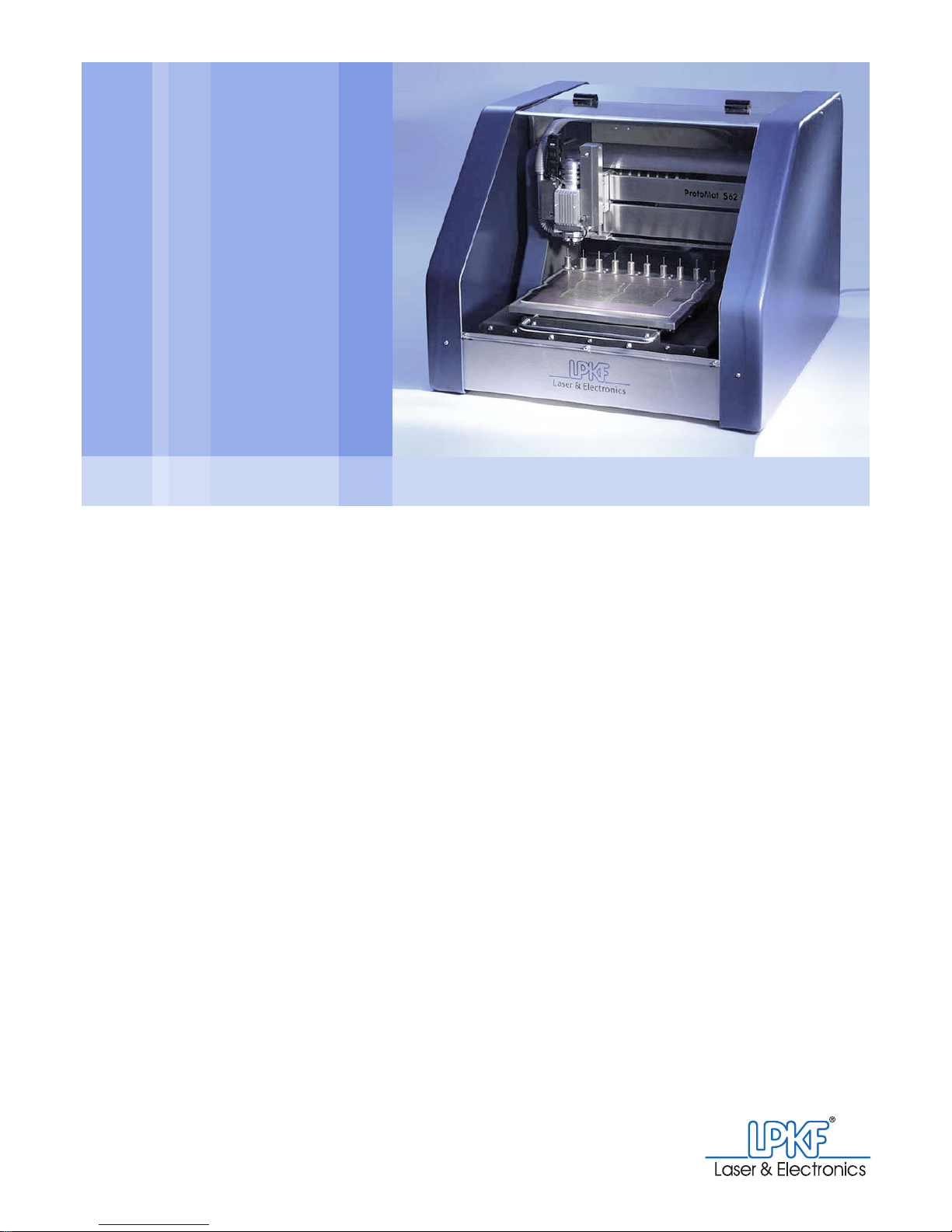
ProtoMat®S62
Operating Manual
7.1, English
Artikelnummer: xxx_xxx
Titelfoto einfügen:
Größe: 11,5 cm x 9,5 cm
Abstand:
links: 8,5 cm
oben: 1,5 cm
Article number: 121 882
Page 2

Page 3

ProtoMat®S62
Operating Manual
7.1, English
LPKF Laser & Electronics AG
Osteriede 7
D-30827 Garbsen
Germany
Phone ++ 49 - (0) 51 31 - 70 95 - 0
Fax ++ 49 - (0) 51 31 - 70 95 - 90
E-Mail [email protected]
Homepage http://www.lpkf.de
Page 4

ProtoMat®S62
Copyright© 2008 LPKF AG Any distribution or copying of this manual or part s of this manual in any form and
use of its contents require the written permission of the LPKF AG. Subject to
modifications.
Translation of the german original
Article number: 121 882
Introduction
The LPKF ProtoMat®S62 is a latest generation compact circuit board
plotter. It is suitable especially for the rapid and safe production of circuit
board prototypes in electronic labs and development departments.
The high number of revolutions (up to 62,000 rpm) ensures the production of accurate structures on different base and housing materials.
Thanks to the integrated Z-axis control, the ProtoMat
®
S62 is ideal for
2.5 dimensional work. Accordingly, for example, front plates for electronic
housings can be produced and previously populated SMD circuit boards
reworked.
By means of the optional camera system also double-sided materials,
for example for multi-layer and RF applications, can be processed precisely. Flexible and rigid/flexible workpieces can be fixed flat on the working surface thanks to the optional vacuum table.
The ProtoMat
®
S62 is controlled via the easy-to-use LPKF BoardMaster
software. The LPKF CircuitCAM software included in the delivery can be
used to import all common CAD data formats and make them ready for
the working process.
Page 5
Information about this document
Operating Manual 7.1 Rev.: 18.06.2008 3
Information about this document
This manual contains important information regarding operation, care
and maintenance of the LPKF circuit board plotter ProtoMat
®
S62. The
manual is directed at persons with basic knowledge in the inst allation and
operation of software-controlled machines. Knowledge regarding the
safety and behavior in workshops as well as regarding the operation of a
computer with Windows 2000/XP are required.
Availability
When working at or with the ProtoMat®S62, this document must be
available in complete and legible condition. It must be within easy reach
near the machine for all the persons entrusted with work on the machine.
As the machine owner, you have to make sure that the machine is only
operated by persons who have read and understood this manual or have
been informed about its contents.
Notations
Different notations enable better orientation in this document.
Symbols and signal words
→ An arrow points to a different location in this document or to another
document specified by name.
WARNING
Danger to life or health.
This symbol indicates a dangerous situation in which in case of
non-observance of the information there is a risk to life or health.
› Informations to avoid the danger are given.
CAUTION
Risk of material damage.
› This symbol indicates a situation which in case of non-observ-
ance of the information can result in material damage.
› Informations to avoid the risks are given.
Tip: The hand indicates tips for easier handling, material use and/or
further processing.
Page 6

Brand names
4 ProtoMat®S62
Bold print The following detailed information is shown in bold print:
• Switches, operating elements, labeled connections
for example power switches.
• Software elements:
– Menu entries, for example File > Open...
– Input boxes, selection boxes and lists, for example T ool Selec tion
List
– Buttons; for example: Cancel
– Windows, dialog boxes, for example input windows Tool
Positions
• Numberings in images
– Numbers in bold print in figures identify numberings (
1) or dimen-
sions (
50 mm).
– Numbers in bold print appearing inside parentheses (1) identify the
number in the figure described.
Italic print The following information is shown in italics:
• Proper names and brand names, for example Windows
(LPKF proper names are not shown in italics.)
• Software messages, for example "The file will be started..."
(The inverted commas are not part of the message.)
Indented headers Indented headings prompt you to carry out an action.
Example:
I. Carrying out an action
If the heading is preceded by a roman numeral (e. g. I), then you have
to carry out further actions to achieve a special work objective.
1. A numbered indented sentence prompts you to carry out one step
of an action.
2. Always carry out the steps of an action in the numbered order.
[ ] Square brackets indicate that no further steps need to be carried out for
this action.
Brand names
The LPKF Logo, LPKF ProtoMat, BoardMaster and LPKF ProConduct
are registered trademarks of LPKF Laser & Electronics AG.
Windows is a brand name of the Microsoft AG.
All other brandnames belong to the respective owner.
Page 7

Table of contents
Operating Manual 7.1 Rev.: 18.06.2008 5
Table of contents
Introduction. . . . . . . . . . . . . . . . . . . . . . . . . . . . . . . . . . . . . . . . . . . . . . . . . . . . . . . . . . 2
Information about this document . . . . . . . . . . . . . . . . . . . . . . . . . . . . . . . . . . . 3
List of figures. . . . . . . . . . . . . . . . . . . . . . . . . . . . . . . . . . . . . . . . . . . . . . . . . . . . . . . 11
1 For your safety 15
1.1 Designated use. . . . . . . . . . . . . . . . . . . . . . . . . . . . . . . . . . . . . . . . . . . . . . . . . 15
1.2 Safety instructions. . . . . . . . . . . . . . . . . . . . . . . . . . . . . . . . . . . . . . . . . . . . . . 17
2 What is what? 21
2.1 Circuit board plotter with acoustic cabinet . . . . . . . . . . . . . . . . . . . . . . . . . . 21
2.2 Milling/drilling head . . . . . . . . . . . . . . . . . . . . . . . . . . . . . . . . . . . . . . . . . . . . . 23
2.3 Traversing table and tool magazine . . . . . . . . . . . . . . . . . . . . . . . . . . . . . . . . 24
2.4 Connecting elements and rating plates. . . . . . . . . . . . . . . . . . . . . . . . . . . . . 25
2.5 LPKF dust extraction. . . . . . . . . . . . . . . . . . . . . . . . . . . . . . . . . . . . . . . . . . . . 27
3 What you should know 29
3.1 The milling/drilling head . . . . . . . . . . . . . . . . . . . . . . . . . . . . . . . . . . . . . . . . . 29
3.1.1 Defined positions . . . . . . . . . . . . . . . . . . . . . . . . . . . . . . . . . . . . . . . . . . . . . 29
3.1.2 Milling depth/width limitation. . . . . . . . . . . . . . . . . . . . . . . . . . . . . . . . . . . . . 30
3.2 The traversing table. . . . . . . . . . . . . . . . . . . . . . . . . . . . . . . . . . . . . . . . . . . . . 32
3.2.1 The pass hole system. . . . . . . . . . . . . . . . . . . . . . . . . . . . . . . . . . . . . . . . . . 33
3.2.2 Material fastening . . . . . . . . . . . . . . . . . . . . . . . . . . . . . . . . . . . . . . . . . . . . . 33
3.3 The tool magazine . . . . . . . . . . . . . . . . . . . . . . . . . . . . . . . . . . . . . . . . . . . . . . 34
3.4 Usable tools . . . . . . . . . . . . . . . . . . . . . . . . . . . . . . . . . . . . . . . . . . . . . . . . . . . 34
3.4.1 Surface tools. . . . . . . . . . . . . . . . . . . . . . . . . . . . . . . . . . . . . . . . . . . . . . . . . 35
3.4.2 Penetrative tools. . . . . . . . . . . . . . . . . . . . . . . . . . . . . . . . . . . . . . . . . . . . . . 37
3.5 The 2.5 D function . . . . . . . . . . . . . . . . . . . . . . . . . . . . . . . . . . . . . . . . . . . . . . 39
3.6 Manual operation . . . . . . . . . . . . . . . . . . . . . . . . . . . . . . . . . . . . . . . . . . . . . . . 40
3.7 Automatic operation . . . . . . . . . . . . . . . . . . . . . . . . . . . . . . . . . . . . . . . . . . . . 41
3.7.1 Production types and phase files . . . . . . . . . . . . . . . . . . . . . . . . . . . . . . . . . 41
3.7.2 Production phases . . . . . . . . . . . . . . . . . . . . . . . . . . . . . . . . . . . . . . . . . . . . 42
3.7.3 Data selection . . . . . . . . . . . . . . . . . . . . . . . . . . . . . . . . . . . . . . . . . . . . . . . . 46
Page 8

Table of contents
6 ProtoMat®S62
4 Manual tasks and settings 47
4.1 Switching on the system. . . . . . . . . . . . . . . . . . . . . . . . . . . . . . . . . . . . . . . . . .47
Switching on the LPKF dust extraction (optional) . . . . . . . . . . . . . . . . . . . . 48
Setting the suction force (optional). . . . . . . . . . . . . . . . . . . . . . . . . . . . . . . . 49
Switching on the circuit board plotter. . . . . . . . . . . . . . . . . . . . . . . . . . . . . . 49
Starting BoardMaster. . . . . . . . . . . . . . . . . . . . . . . . . . . . . . . . . . . . . . . . . . 50
Checking the connection settings (if necessary) . . . . . . . . . . . . . . . . . . . . . 51
4.2 Switching off the system . . . . . . . . . . . . . . . . . . . . . . . . . . . . . . . . . . . . . . . . .52
Quitting BoardMaster. . . . . . . . . . . . . . . . . . . . . . . . . . . . . . . . . . . . . . . . . . 52
Switching off the circuit board plotter. . . . . . . . . . . . . . . . . . . . . . . . . . . . . . 53
Switching off the LPKF dust extraction . . . . . . . . . . . . . . . . . . . . . . . . . . . . 53
4.3 Finding out about BoardMaster . . . . . . . . . . . . . . . . . . . . . . . . . . . . . . . . . . . . 54
4.3.1 The user interface . . . . . . . . . . . . . . . . . . . . . . . . . . . . . . . . . . . . . . . . . . . . 54
4.3.2 Frequently used functions . . . . . . . . . . . . . . . . . . . . . . . . . . . . . . . . . . . . . . 56
4.4 Positioning the milling/drilling head . . . . . . . . . . . . . . . . . . . . . . . . . . . . . . . .58
Moving the milling/drilling head to a predefined position . . . . . . . . . . . . . . . 59
Moving the milling/drilling head step by step in the X/Y direction . . . . . . . . 60
Moving the milling/drilling head with the mouse. . . . . . . . . . . . . . . . . . . . . . 60
Moving the milling/drilling head vertically. . . . . . . . . . . . . . . . . . . . . . . . . . . 61
4.5 Mounting/Dismounting the milling depth limiter base. . . . . . . . . . . . . . . . . . 62
Dismounting the plastic base/brush head . . . . . . . . . . . . . . . . . . . . . . . . . . 62
Mounting the plastic base/brush head . . . . . . . . . . . . . . . . . . . . . . . . . . . . . 63
4.6 Loading. . . . . . . . . . . . . . . . . . . . . . . . . . . . . . . . . . . . . . . . . . . . . . . . . . . . . . . .64
4.6.1 Loading and setting up the base material . . . . . . . . . . . . . . . . . . . . . . . . . . 64
Loading base material . . . . . . . . . . . . . . . . . . . . . . . . . . . . . . . . . . . . . . . . . 64
Defining the work area. . . . . . . . . . . . . . . . . . . . . . . . . . . . . . . . . . . . . . . . . 65
Defining the material height and z values . . . . . . . . . . . . . . . . . . . . . . . . . . 66
4.6.2 Setting up tools . . . . . . . . . . . . . . . . . . . . . . . . . . . . . . . . . . . . . . . . . . . . . . 67
Opening the tool magazine dialogue box. . . . . . . . . . . . . . . . . . . . . . . . . . . 67
Assigning tool positions . . . . . . . . . . . . . . . . . . . . . . . . . . . . . . . . . . . . . . . . 68
4.6.3 Inserting tools. . . . . . . . . . . . . . . . . . . . . . . . . . . . . . . . . . . . . . . . . . . . . . . . 70
Inserting tools. . . . . . . . . . . . . . . . . . . . . . . . . . . . . . . . . . . . . . . . . . . . . . . . 70
4.7 Selecting a tool for processing . . . . . . . . . . . . . . . . . . . . . . . . . . . . . . . . . . . .70
Picking up/Setting down a tool. . . . . . . . . . . . . . . . . . . . . . . . . . . . . . . . . . . 71
4.8 Setting the focus (VisionSystem only) . . . . . . . . . . . . . . . . . . . . . . . . . . . . . .71
Setting the focus to the saved value . . . . . . . . . . . . . . . . . . . . . . . . . . . . . . 71
Adjusting the focus position . . . . . . . . . . . . . . . . . . . . . . . . . . . . . . . . . . . . . 72
Page 9

Table of contents
Operating Manual 7.1 Rev.: 18.06.2008 7
4.9 Drilling. . . . . . . . . . . . . . . . . . . . . . . . . . . . . . . . . . . . . . . . . . . . . . . . . . . . . . . . 73
Drilling a hole . . . . . . . . . . . . . . . . . . . . . . . . . . . . . . . . . . . . . . . . . . . . . . . . 73
4.10 Milling. . . . . . . . . . . . . . . . . . . . . . . . . . . . . . . . . . . . . . . . . . . . . . . . . . . . . . . . 74
Creating a milling track . . . . . . . . . . . . . . . . . . . . . . . . . . . . . . . . . . . . . . . . . 75
Adjusting the milling depth (cylindrical tools) . . . . . . . . . . . . . . . . . . . . . . . . 76
Adjusting the milling width (Universal Cutter and Micro Cutter only) . . . . . . 76
4.11 Creating a pass hole system (basic equipment) . . . . . . . . . . . . . . . . . . . . . 77
Preparing the circuit board plotter. . . . . . . . . . . . . . . . . . . . . . . . . . . . . . . . . 77
Drilling pass holes into pass hole strips . . . . . . . . . . . . . . . . . . . . . . . . . . . . 78
Drilling pass holes into the drilling underlay . . . . . . . . . . . . . . . . . . . . . . . . . 80
4.12 Creating a pass hole system for the vacuum table. . . . . . . . . . . . . . . . . . . 81
Preparing the circuit board plotter and vacuum table. . . . . . . . . . . . . . . . . . 82
4.12.1 Drilling pass holes into pass hole strips . . . . . . . . . . . . . . . . . . . . . . . . . . . 83
Setting parameters for drilling pass holes. . . . . . . . . . . . . . . . . . . . . . . . . . . 83
Setting the machine parameters for drilling pass hole strips . . . . . . . . . . . . 84
Drilling pass holes into pass hole strips . . . . . . . . . . . . . . . . . . . . . . . . . . . . 84
4.12.2 Drilling pass holes into the sinter plate . . . . . . . . . . . . . . . . . . . . . . . . . . . . 86
Adjusting machine parameters . . . . . . . . . . . . . . . . . . . . . . . . . . . . . . . . . . . 86
Drilling pass holes into the sinter plate. . . . . . . . . . . . . . . . . . . . . . . . . . . . . 87
4.13 Inserting pass hole pins. . . . . . . . . . . . . . . . . . . . . . . . . . . . . . . . . . . . . . . . . 88
Inserting pass hole pins . . . . . . . . . . . . . . . . . . . . . . . . . . . . . . . . . . . . . . . . 89
5 Working sequence in automatic mode 91
5.1 Preparation . . . . . . . . . . . . . . . . . . . . . . . . . . . . . . . . . . . . . . . . . . . . . . . . . . . . 91
5.2 Defining the production type . . . . . . . . . . . . . . . . . . . . . . . . . . . . . . . . . . . . . 91
Selecting a phase file . . . . . . . . . . . . . . . . . . . . . . . . . . . . . . . . . . . . . . . . . . 91
5.3 Setting up a job . . . . . . . . . . . . . . . . . . . . . . . . . . . . . . . . . . . . . . . . . . . . . . . . 92
Creating a new job . . . . . . . . . . . . . . . . . . . . . . . . . . . . . . . . . . . . . . . . . . . . 93
Opening an existing job . . . . . . . . . . . . . . . . . . . . . . . . . . . . . . . . . . . . . . . . 93
Aligning/Distributing projects. . . . . . . . . . . . . . . . . . . . . . . . . . . . . . . . . . . . . 94
Saving a job . . . . . . . . . . . . . . . . . . . . . . . . . . . . . . . . . . . . . . . . . . . . . . . . . 95
5.4 Setting up the tools . . . . . . . . . . . . . . . . . . . . . . . . . . . . . . . . . . . . . . . . . . . . . 95
Opening the Tool Positions input window. . . . . . . . . . . . . . . . . . . . . . . . . . . 96
Configuring tools in the tool magazine . . . . . . . . . . . . . . . . . . . . . . . . . . . . . 97
Inserting tools . . . . . . . . . . . . . . . . . . . . . . . . . . . . . . . . . . . . . . . . . . . . . . . . 98
Page 10

Table of contents
8 ProtoMat®S62
5.5 Selecting/Setting up a production phase . . . . . . . . . . . . . . . . . . . . . . . . . . . .99
Selecting the production phase . . . . . . . . . . . . . . . . . . . . . . . . . . . . . . . . . . 99
5.5.1 Selecting tools (optional) . . . . . . . . . . . . . . . . . . . . . . . . . . . . . . . . . . . . . . . 99
Selecting tools . . . . . . . . . . . . . . . . . . . . . . . . . . . . . . . . . . . . . . . . . . . . . . 100
5.5.2 Activating data . . . . . . . . . . . . . . . . . . . . . . . . . . . . . . . . . . . . . . . . . . . . . . 101
Activating all data. . . . . . . . . . . . . . . . . . . . . . . . . . . . . . . . . . . . . . . . . . . . 101
Activating areas of data elements . . . . . . . . . . . . . . . . . . . . . . . . . . . . . . . 101
Activating data segments by index number . . . . . . . . . . . . . . . . . . . . . . . . 102
Deactivating all data. . . . . . . . . . . . . . . . . . . . . . . . . . . . . . . . . . . . . . . . . . 102
Deactivating data areas . . . . . . . . . . . . . . . . . . . . . . . . . . . . . . . . . . . . . . . 102
5.6 Setting up 2.5 D processing (optional) . . . . . . . . . . . . . . . . . . . . . . . . . . . . .103
5.6.1 Setting up contour milling with 2.5 D mode . . . . . . . . . . . . . . . . . . . . . . . . 104
Activating the 2.5 D mode for a phase. . . . . . . . . . . . . . . . . . . . . . . . . . . . 104
Setting the moving-free height. . . . . . . . . . . . . . . . . . . . . . . . . . . . . . . . . . 105
5.6.2 Setting up surface milling with 2.5 D mode . . . . . . . . . . . . . . . . . . . . . . . . 105
5.7 Starting production . . . . . . . . . . . . . . . . . . . . . . . . . . . . . . . . . . . . . . . . . . . . .106
Starting a production phase. . . . . . . . . . . . . . . . . . . . . . . . . . . . . . . . . . . . 106
Milling contours in 2.5 D mode (optional). . . . . . . . . . . . . . . . . . . . . . . . . . 107
Adjusting the milling depth/width . . . . . . . . . . . . . . . . . . . . . . . . . . . . . . . . 108
5.7.1 Stopping the production phase . . . . . . . . . . . . . . . . . . . . . . . . . . . . . . . . . 109
Interrupting the production phase . . . . . . . . . . . . . . . . . . . . . . . . . . . . . . . 109
5.8 Ending production. . . . . . . . . . . . . . . . . . . . . . . . . . . . . . . . . . . . . . . . . . . . . .109
Saving the production status . . . . . . . . . . . . . . . . . . . . . . . . . . . . . . . . . . . 109
Aborting production . . . . . . . . . . . . . . . . . . . . . . . . . . . . . . . . . . . . . . . . . . 110
6 Care and maintenance 111
6.1 Caring/inspecting . . . . . . . . . . . . . . . . . . . . . . . . . . . . . . . . . . . . . . . . . . . . . .111
Cleaning the surfaces . . . . . . . . . . . . . . . . . . . . . . . . . . . . . . . . . . . . . . . . 111
Carrying out a visual inspection. . . . . . . . . . . . . . . . . . . . . . . . . . . . . . . . . 111
Page 11

Table of contents
Operating Manual 7.1 Rev.: 18.06.2008 9
6.2 Maintaining milling depth limiter and collet chuck. . . . . . . . . . . . . . . . . . . 112
6.2.1 Removing and cleaning the milling depth limiter. . . . . . . . . . . . . . . . . . . . . 112
Removing the milling depth limiter . . . . . . . . . . . . . . . . . . . . . . . . . . . . . . . 112
Cleaning the milling depth limiter . . . . . . . . . . . . . . . . . . . . . . . . . . . . . . . . 114
6.2.2 Removing and cleaning the collet chuck. . . . . . . . . . . . . . . . . . . . . . . . . . . 114
Opening the collet chuck . . . . . . . . . . . . . . . . . . . . . . . . . . . . . . . . . . . . . . 114
Removing the collet chuck . . . . . . . . . . . . . . . . . . . . . . . . . . . . . . . . . . . . . 116
Cleaning the collet chuck and the collet chuck holder . . . . . . . . . . . . . . . . 117
6.2.3 Mounting the collet chuck and the milling depth limiter. . . . . . . . . . . . . . . . 118
Screwing in the collet chuck . . . . . . . . . . . . . . . . . . . . . . . . . . . . . . . . . . . . 118
Mounting the milling depth limiter. . . . . . . . . . . . . . . . . . . . . . . . . . . . . . . . 118
6.3 Replacing fuses . . . . . . . . . . . . . . . . . . . . . . . . . . . . . . . . . . . . . . . . . . . . . . . 119
Removing the side wall of the acoustic cabinet . . . . . . . . . . . . . . . . . . . . . 119
Replacing the fuses . . . . . . . . . . . . . . . . . . . . . . . . . . . . . . . . . . . . . . . . . . 120
Mounting the side wall of the acoustic cabinet . . . . . . . . . . . . . . . . . . . . . . 121
6.4 Configuring the tool holder position . . . . . . . . . . . . . . . . . . . . . . . . . . . . . . 121
6.4.1 Configuring the tool holder position (without camera). . . . . . . . . . . . . . . . . 121
Defining the milling/drilling head offset. . . . . . . . . . . . . . . . . . . . . . . . . . . . 121
Activating the service functions. . . . . . . . . . . . . . . . . . . . . . . . . . . . . . . . . . 122
Testing the tool holder position. . . . . . . . . . . . . . . . . . . . . . . . . . . . . . . . . . 124
Correcting the tool holder position . . . . . . . . . . . . . . . . . . . . . . . . . . . . . . . 125
6.4.2 Determining the tool holder position with VisionSystem. . . . . . . . . . . . . . . 126
Setting the camera offset . . . . . . . . . . . . . . . . . . . . . . . . . . . . . . . . . . . . . . 126
Preparing the tool magazine for determining the position. . . . . . . . . . . . . . 128
Calling the service functions. . . . . . . . . . . . . . . . . . . . . . . . . . . . . . . . . . . . 129
Reading in the position data. . . . . . . . . . . . . . . . . . . . . . . . . . . . . . . . . . . . 130
6.5 Adjusting the camera (only with VisionSystem). . . . . . . . . . . . . . . . . . . . . 131
Setting the camera offset . . . . . . . . . . . . . . . . . . . . . . . . . . . . . . . . . . . . . . 132
6.5.1 Calibrating fiducial recognition . . . . . . . . . . . . . . . . . . . . . . . . . . . . . . . . . . 134
Preparing the fiducial recognition . . . . . . . . . . . . . . . . . . . . . . . . . . . . . . . . 134
Determining the fiducial diameter. . . . . . . . . . . . . . . . . . . . . . . . . . . . . . . . 137
6.6 Changing the dust extraction filter. . . . . . . . . . . . . . . . . . . . . . . . . . . . . . . . 140
Page 12

Table of contents
10 ProtoMat®S62
7 Error messages/Malfunctions 141
8 Decommissioning, transport, disposal 143
8.1 Decommissioning . . . . . . . . . . . . . . . . . . . . . . . . . . . . . . . . . . . . . . . . . . . . . .143
Switching the ProtoMat
®
S62 off.. . . . . . . . . . . . . . . . . . . . . . . . . . . . . . . . 143
Disconnect the connecting cables.. . . . . . . . . . . . . . . . . . . . . . . . . . . . . . . 143
8.2 Transport . . . . . . . . . . . . . . . . . . . . . . . . . . . . . . . . . . . . . . . . . . . . . . . . . . . . .144
Fitting transport braces . . . . . . . . . . . . . . . . . . . . . . . . . . . . . . . . . . . . . . . 144
8.3 Disposal . . . . . . . . . . . . . . . . . . . . . . . . . . . . . . . . . . . . . . . . . . . . . . . . . . . . . .144
8.3.1 Machine parts and components. . . . . . . . . . . . . . . . . . . . . . . . . . . . . . . . . 144
8.3.2 Consumables . . . . . . . . . . . . . . . . . . . . . . . . . . . . . . . . . . . . . . . . . . . . . . . 144
9 Technical data 145
10 LPKF Service 147
11 EC Declaration of Conformity 149
12 Index 151
Page 13

List of figures
Operating Manual 7.1 Rev.: 18.06.2008 11
List of figures
Fig. 1: ProtoMat®S62 basic equipment . . . . . . . . . . . . . . . . . . . . . . . . . . . . . . . . . . . . . . 21
Fig. 2: Optional components . . . . . . . . . . . . . . . . . . . . . . . . . . . . . . . . . . . . . . . . . . . . . . . 22
Fig. 3: Milling/drilling head (front view) . . . . . . . . . . . . . . . . . . . . . . . . . . . . . . . . . . . . . . . 23
Fig. 4: Traversing table with tool magazine . . . . . . . . . . . . . . . . . . . . . . . . . . . . . . . . . . . . 24
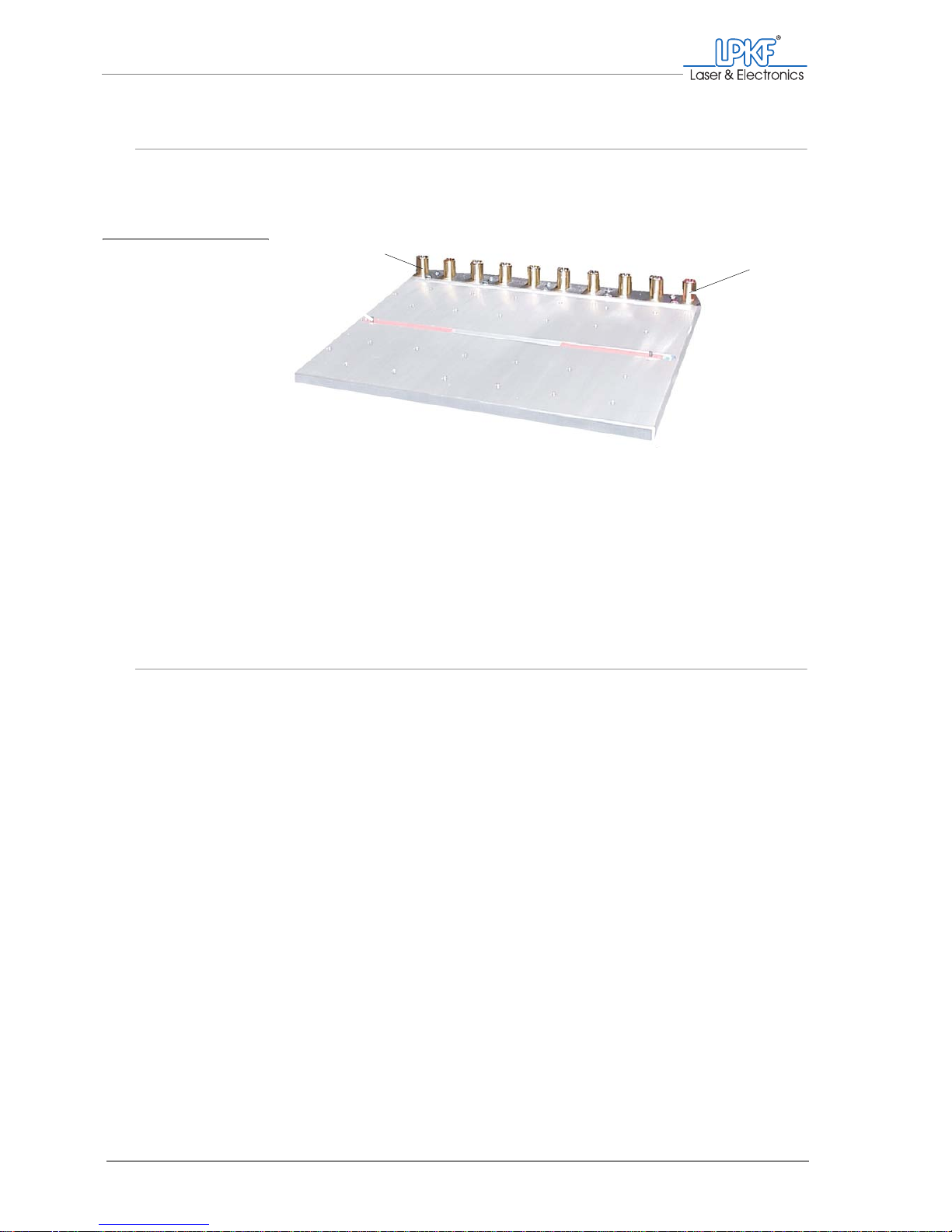
Fig. 5: Vacuum table (optional) . . . . . . . . . . . . . . . . . . . . . . . . . . . . . . . . . . . . . . . . . . . . . 24
Fig. 6: Main switch with mains connection . . . . . . . . . . . . . . . . . . . . . . . . . . . . . . . . . . . . 25
Fig. 7: Dust extraction and data connections . . . . . . . . . . . . . . . . . . . . . . . . . . . . . . . . . . 26
Fig. 8: Control unit with data connections . . . . . . . . . . . . . . . . . . . . . . . . . . . . . . . . . . . . . 26
Fig. 9: LPKF dust extraction . . . . . . . . . . . . . . . . . . . . . . . . . . . . . . . . . . . . . . . . . . . . . . . 27
Fig. 10: Defined positions of the milling/drilling head . . . . . . . . . . . . . . . . . . . . . . . . . . . . . 29
Fig. 11: Setting wheel for milling depth limiter . . . . . . . . . . . . . . . . . . . . . . . . . . . . . . . . . . . 30
Fig. 12: Milling width with Universal Cutter and Micro Cutter . . . . . . . . . . . . . . . . . . . . . . . 31
Fig. 13: Pass hole system . . . . . . . . . . . . . . . . . . . . . . . . . . . . . . . . . . . . . . . . . . . . . . . . . . 32
Fig. 14: Turning the material through the mirror axis . . . . . . . . . . . . . . . . . . . . . . . . . . . . . 33
Fig. 15: Tool positions . . . . . . . . . . . . . . . . . . . . . . . . . . . . . . . . . . . . . . . . . . . . . . . . . . . . . 34
Fig. 16: 2,5 D processing (application examples)) . . . . . . . . . . . . . . . . . . . . . . . . . . . . . . . 39
Fig. 17: Dust extraction - operating modes . . . . . . . . . . . . . . . . . . . . . . . . . . . . . . . . . . . . 48
Fig. 18: Dialog box Tool status . . . . . . . . . . . . . . . . . . . . . . . . . . . . . . . . . . . . . . . . . . . . . . 50
Fig. 19: Input window Connect... . . . . . . . . . . . . . . . . . . . . . . . . . . . . . . . . . . . . . . . . . . . . . 51
Fig. 20: BoardMaster user interface . . . . . . . . . . . . . . . . . . . . . . . . . . . . . . . . . . . . . . . . . . 54
Fig. 21: Removing the plastic base from the milling depth limiter . . . . . . . . . . . . . . . . . . . . 62
Fig. 22: Fitting the plastic base on the milling depth limiter . . . . . . . . . . . . . . . . . . . . . . . . . 63
Fig. 23: Defining the material size and position . . . . . . . . . . . . . . . . . . . . . . . . . . . . . . . . . 66
Fig. 24: Tool positions input window . . . . . . . . . . . . . . . . . . . . . . . . . . . . . . . . . . . . . . . . . . 67
Fig. 25: Assigning tool positions . . . . . . . . . . . . . . . . . . . . . . . . . . . . . . . . . . . . . . . . . . . . . 68
Fig. 26: Defined tool positions . . . . . . . . . . . . . . . . . . . . . . . . . . . . . . . . . . . . . . . . . . . . . . . 69
Fig. 27: Adjusting the focus position . . . . . . . . . . . . . . . . . . . . . . . . . . . . . . . . . . . . . . . . . . 72
Fig. 28: Selecting pass hole drills for pass hole strips . . . . . . . . . . . . . . . . . . . . . . . . . . . . 78
Fig. 29: BoardMaster message "Drill pass hole?" . . . . . . . . . . . . . . . . . . . . . . . . . . . . . . . . 78
Fig. 30: BoardMaster message "Depth limiter removed" . . . . . . . . . . . . . . . . . . . . . . . . . . 79
Fig. 31: Selecting pass hole drills for base material/drilling underlay . . . . . . . . . . . . . . . . . 80
Fig. 32: Pass hole strips in the vacuum table . . . . . . . . . . . . . . . . . . . . . . . . . . . . . . . . . . . 82
Fig. 33: Setting parameters for drilling pass holes . . . . . . . . . . . . . . . . . . . . . . . . . . . . . . . 83
Fig. 34: Selecting pass hole drills for pass hole strips . . . . . . . . . . . . . . . . . . . . . . . . . . . . 84
Page 14

List of figures
12 ProtoMat®S62
Fig. 35: BoardMaster message "Drill pass hole?" . . . . . . . . . . . . . . . . . . . . . . . . . . . . . . . .85
Fig. 36: BoardMaster message "Depth limiter removed" . . . . . . . . . . . . . . . . . . . . . . . . . . .85
Fig. 37: Machine parameters . . . . . . . . . . . . . . . . . . . . . . . . . . . . . . . . . . . . . . . . . . . . . . . .86
Fig. 38: Selecting pass hole drills for pass hole strips . . . . . . . . . . . . . . . . . . . . . . . . . . . . .87
Fig. 39: Press-in tool with pass hole pin . . . . . . . . . . . . . . . . . . . . . . . . . . . . . . . . . . . . . . . .89
Fig. 40: Positioning a project . . . . . . . . . . . . . . . . . . . . . . . . . . . . . . . . . . . . . . . . . . . . . . . .94
Fig. 41: Tool Positions input window . . . . . . . . . . . . . . . . . . . . . . . . . . . . . . . . . . . . . . . . . .96
Fig. 42: Assigning tool positions . . . . . . . . . . . . . . . . . . . . . . . . . . . . . . . . . . . . . . . . . . . . . . 97
Fig. 43: Defined tool positions . . . . . . . . . . . . . . . . . . . . . . . . . . . . . . . . . . . . . . . . . . . . . . .97
Fig. 44: Selecting tools . . . . . . . . . . . . . . . . . . . . . . . . . . . . . . . . . . . . . . . . . . . . . . . . . . . .100
Fig. 45: Activating the 2.5 D mode in the phases dialogue box . . . . . . . . . . . . . . . . . . . . .104
Fig. 46: Setting the moving-free height . . . . . . . . . . . . . . . . . . . . . . . . . . . . . . . . . . . . . . .105
Fig. 47: 2.5 D mode: Configuring . . . . . . . . . . . . . . . . . . . . . . . . . . . . . . . . . . . . . . . . . . . .107
Fig. 48: Adjusting the milling width . . . . . . . . . . . . . . . . . . . . . . . . . . . . . . . . . . . . . . . . . . .108
Fig. 49: Message when aborting production . . . . . . . . . . . . . . . . . . . . . . . . . . . . . . . . . . .110
Fig. 50: Collet chuck tools . . . . . . . . . . . . . . . . . . . . . . . . . . . . . . . . . . . . . . . . . . . . . . . . .112
Fig. 51: Dismantling the milling depth limiter . . . . . . . . . . . . . . . . . . . . . . . . . . . . . . . . . . .113
Fig. 52: Dismantling the milling depth limiter . . . . . . . . . . . . . . . . . . . . . . . . . . . . . . . . . . .113
Fig. 53: Setting the milling/drilling head offset . . . . . . . . . . . . . . . . . . . . . . . . . . . . . . . . . .115
Fig. 54: Tool with collet chuck wrench . . . . . . . . . . . . . . . . . . . . . . . . . . . . . . . . . . . . . . . .116
Fig. 55: Unscrewing the collet chuck . . . . . . . . . . . . . . . . . . . . . . . . . . . . . . . . . . . . . . . . .116
Fig. 56: Cleaning the collet chuck holder . . . . . . . . . . . . . . . . . . . . . . . . . . . . . . . . . . . . . . 117
Fig. 57: Cleaning the collet chuck holder . . . . . . . . . . . . . . . . . . . . . . . . . . . . . . . . . . . . . . 117
Fig. 58: Removing the side wall of the acoustic cabinet . . . . . . . . . . . . . . . . . . . . . . . . . . .119
Fig. 59: Orientation of the fuse holder . . . . . . . . . . . . . . . . . . . . . . . . . . . . . . . . . . . . . . . .120
Fig. 60: Setting the milling/drilling head offset . . . . . . . . . . . . . . . . . . . . . . . . . . . . . . . . . .122
Fig. 61: Setting the milling/drilling head offset . . . . . . . . . . . . . . . . . . . . . . . . . . . . . . . . . .123
Fig. 62: Tool Box with service functions . . . . . . . . . . . . . . . . . . . . . . . . . . . . . . . . . . . . . . .123
Fig. 63: Setting the milling/drilling head offset . . . . . . . . . . . . . . . . . . . . . . . . . . . . . . . . . .126
Fig. 64: Positioning the camera image above the bore . . . . . . . . . . . . . . . . . . . . . . . . . . .127
Fig. 65: Setting the milling/drilling head offset . . . . . . . . . . . . . . . . . . . . . . . . . . . . . . . . . .128
Fig. 66: Measuring insert for determining the position with VisionSystem . . . . . . . . . . . . .128
Fig. 67: Setting the milling/drilling head offset . . . . . . . . . . . . . . . . . . . . . . . . . . . . . . . . . .129
Fig. 68: Tool magazine with service functions . . . . . . . . . . . . . . . . . . . . . . . . . . . . . . . . . .130
Fig. 69: Setting the camera offset . . . . . . . . . . . . . . . . . . . . . . . . . . . . . . . . . . . . . . . . . . .132
Fig. 70: Positioning the camera above the bore . . . . . . . . . . . . . . . . . . . . . . . . . . . . . . . . . 133
Page 15

List of figures
Operating Manual 7.1 Rev.: 18.06.2008 13
Fig. 71: Bore in the camera image window . . . . . . . . . . . . . . . . . . . . . . . . . . . . . . . . . . . . 134
Fig. 72: Setting fiducial recognition . . . . . . . . . . . . . . . . . . . . . . . . . . . . . . . . . . . . . . . . . . 135
Fig. 73: Fiducial calibration . . . . . . . . . . . . . . . . . . . . . . . . . . . . . . . . . . . . . . . . . . . . . . . . 135
Fig. 74: Calibration not possible . . . . . . . . . . . . . . . . . . . . . . . . . . . . . . . . . . . . . . . . . . . . 136
Fig. 75: Calibration successful . . . . . . . . . . . . . . . . . . . . . . . . . . . . . . . . . . . . . . . . . . . . . 136
Fig. 76: Measured values in the camera image . . . . . . . . . . . . . . . . . . . . . . . . . . . . . . . . 137
Fig. 77: Fiducial settings . . . . . . . . . . . . . . . . . . . . . . . . . . . . . . . . . . . . . . . . . . . . . . . . . . 138
Fig. 78: Calibration settings . . . . . . . . . . . . . . . . . . . . . . . . . . . . . . . . . . . . . . . . . . . . . . . . 138
Fig. 79: Calibration complete . . . . . . . . . . . . . . . . . . . . . . . . . . . . . . . . . . . . . . . . . . . . . . 139
Fig. 80: Fiducial settings . . . . . . . . . . . . . . . . . . . . . . . . . . . . . . . . . . . . . . . . . . . . . . . . . . 139
Fig. 81: Measured values in the camera image . . . . . . . . . . . . . . . . . . . . . . . . . . . . . . . . 140
Page 16

For your notes
14 ProtoMat®S62
Page 17

For your safety
Operating Manual 7.1 Rev.: 18.06.2008 15
1. For your safety
In this chapter you will find information concerning proper use, liability a nd safety in connection
with the operation of the ProtoMat
®
S62.
If, after reading this manual, a situation should arise in which you are not sure how to use or
service the ProtoMat
®
S62, you should contact LPKF Support or consult a person skilled in the
art.
1.1 Designated use
The ProtoMat®S62 has been designed for the production of electric circuit boards with up to six layers and the processing of a variety of sign
and housing materials.
The ProtoMat
®
S62 can be used to:
• Mill and drill single-sided and double-sided printed circuit boards
• Mill and drill multi-layer materials
• Mill SMD solder paste stencils
• Mill solder stop foils
• Engrave housing plates and signs
• Mill cut-outs and contours
• Drill through flat materials
The ProtoMat
®
S62 is able to process the following materials:
• GFK/CFK base material
• PTFE/ceramic composite base material
• Wood
• Non-ferrous metals
– Aluminium acc. to DIN EN 573: EN AW-6012)
– Brass acc. to DIN EN 1412: CW603N
• Plastics
– Polyoxymethylenes
– ABS copolymers
The ProtoMat
®
S62 may only be used for the applications and materials
cited in this document.
The circuit board plotter may only be used together with the version of the
LPKF Software BoardMaster included in the scope of delivery. If you
want to use a different BoardMaster version, please contact the LPKF
Support first.
Page 18

Designated use
16 ProtoMat®S62
Operation of the circuit board plotter is only permitted subject to sufficient
dust extraction provision, which must include fine dust filtering. We recommend the use of the LPKF dust extraction with integrated HEPA filter.
If you want to use a different system for dust extraction, you should contact LPKF Service first.
Improper use The ProtoMat
®
S62 must not be used for processing highly combustible
materials, sealed containers, hollow pieces, textiles or foodstuffs. The
processing of parts of the body (e.g. finger nails) is not permitted.
If you are not sure about the use of the materials to be processed, you
should contact LPKF Support.
Liability for function and damage
The ProtoMat®S62 has been designed and built in accordance with the
state of the art and acknowledged safety engineering guidelines.
Nevertheless, its use may constitute a risk to the life and limb of the user
or of third parties, or cause damage to the machine and to other
equipment or property.
Disclaimer The manufacturer/seller cannot be held liable for damage caused by the
following actions/conditions:
• Improper handling, including any use not mentioned in this manual.
• Use in an unsuitable environment
• Installation and operation by insufficiently informed or unauthorised
persons
• Non-compliance with legal safety requirements
• Non-observance of technical information
• Installation carried out incorrectly
• Insufficient supply facilities
• Missing, faulty or insufficient maintenance
• Unauthorised technical modifications
• Use of non-original spare parts and those not specifically designed
for this machine/device
• Use of non-approved workpieces and/or materials
Page 19
For your safety
Operating Manual 7.1 Rev.: 18.06.2008 17
1.2 Safety instructions
WARNING
Risk of death by electric shock!
Missing or insufficient electrical fuse protection can result in fatal
electric shocks and/or fire.
› Use only fuses of type T4L 250 V.
› Fuse holders must
NEVER be bridged.
WARNING
Risk of injury caused by pointed/sharp tools!
Improper use can cause cuts and stab injuries.
› Handle tools carefully and keep them in the tool box when not in
use.
WARNING
Risk of injury!
When opened, the cover of the acoustic cabinet can drop down
due to impact shocks or vibrations. This can result in limbs being
broken or crushed.
› When opening the cover of the acoustic cabinet make sure that
it engages in the uppermost position and cannot drop down as
a result of vibrations or the influence of third parties.
WARNING
Dusts and gases are hazardous to your health!
The processing of the materials can give rise to dusts and gases
hazardous to your health.
› Ensure that the dust extraction is switched on when processing
materials. Extract the dust and material residues or remove
them with a brush or moistened cloth; do
NOT blow com-
pressed air through.
CAUTION
Material damage due to incorrect tool positioning!
The milling/drilling head, spindle and the tool can become dam-
aged if the tool positions indicated in BoardMaster do not correspond to the actual fitting of the circuit board plotter.
› Ensure that the settings in the Tool Status window corresponds
to the actual fitting of the circuit board plotter.
General safety instructions
› Read the installation instructions/operating manual before
operating the machine. In case of uncertainties ask a person
qualified in the art or contact LPKF Support.
› Use the machine only in accordance with its proper use.
› Never operate the machine in environments subject to fire or
explosion hazards.
› Operate the machine only in a suitable environment.
(Page 1 of 3)
Page 20
Safety instructions
18 ProtoMat®S62
› Protect the machine against direct sunlight, humidity and fly-
ing sparks.
› Operate the machine only with accessories approved by LPKF
and use only original LPKF tools.
› Use the machine only in perfect condition. Prior to each use,
perform a visual inspection. Look out in particular for damaged cables and hoses.
› Make sure that the safety devices are in perfect working order.
It is prohibited to ignore and bridge safety devices or to render
them inoperable.
› Make sure that there is no risk of stumbling caused by cables
and hoses.
› Have the machine operated, serviced and repaired by suffi-
ciently qualified and authorised personnel only.
› Repairs must only be carried out by qualified LPKF personnel
or following consultation with LPKF Support.
› Keep children away from the work area.
› Do not eat, drink or smoke in the workshop/work area.
› Observe the general and legal regulations for accident preven-
tion and environmental protection.
› You must wear the prescribed protective equipment at all
times when operating, servicing and repairing the machine.
› When handling the circuit board plotter, make sure that the
machine cannot start (unintentionally) or be operated by third
parties, for example via the computer.
› Unplug the machine from the mains prior to commencing any
maintenance work.
› Regular care and maintenance are essential.
General safety instructions (Continuation)
(Page 2 of 3)
Page 21

For your safety
Operating Manual 7.1 Rev.: 18.06.2008 19
› If evidence of damage or malfunctions is found, the device
must be brought to a standstill immediately. Have any malfunctions rectified immediately. If the damage cannot be put
right, the machine must be taken out of operation and secured
against being switched on.
› Extract the dust and material residues in the machine or
remove them with a brush. Do
NOT blow compressed air
through!
General safety instructions (Continuation)
(Page 3 of 3)
Page 22

For your notes
20 ProtoMat®S62
Page 23
What is what?
Operating Manual 7.1 Rev.: 18.06.2008 21
2. What is what?
In this chapter you get to know the components and operating e lements of the ProtoMat®S62.
Before installing the machine or putting it into operation, first familiarise yourself with the individual components.
2.1 Circuit board plotter with acoustic cabinet
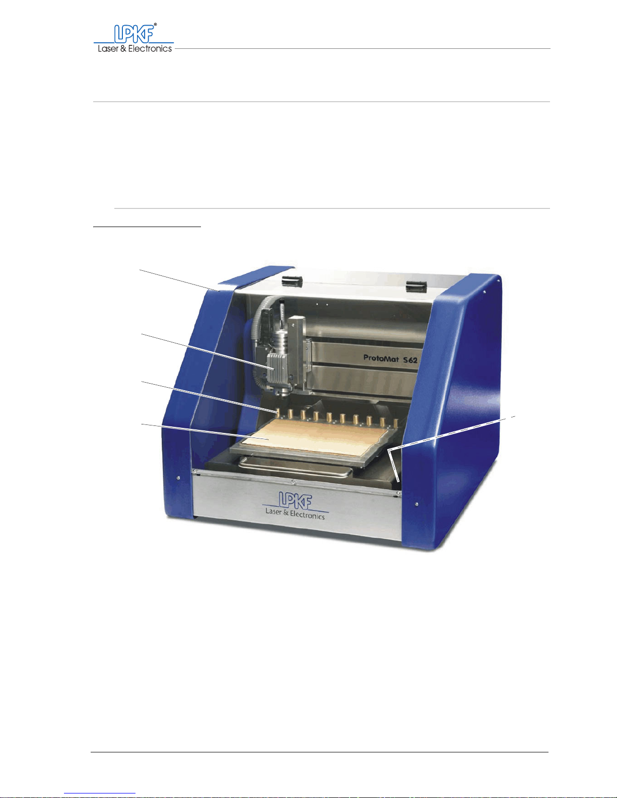
Fig. 1: ProtoMat®S62 basic equipment
1 Acoustic cabinet
2 Milling/drilling head
3 Tool magazine
4 Traversing table (with base material)
5 Main switch (in the acoustic cabinet)
1
2
3
4
5
Page 24
Circuit board plotter with acoustic cabinet
22 ProtoMat®S62
Optional components
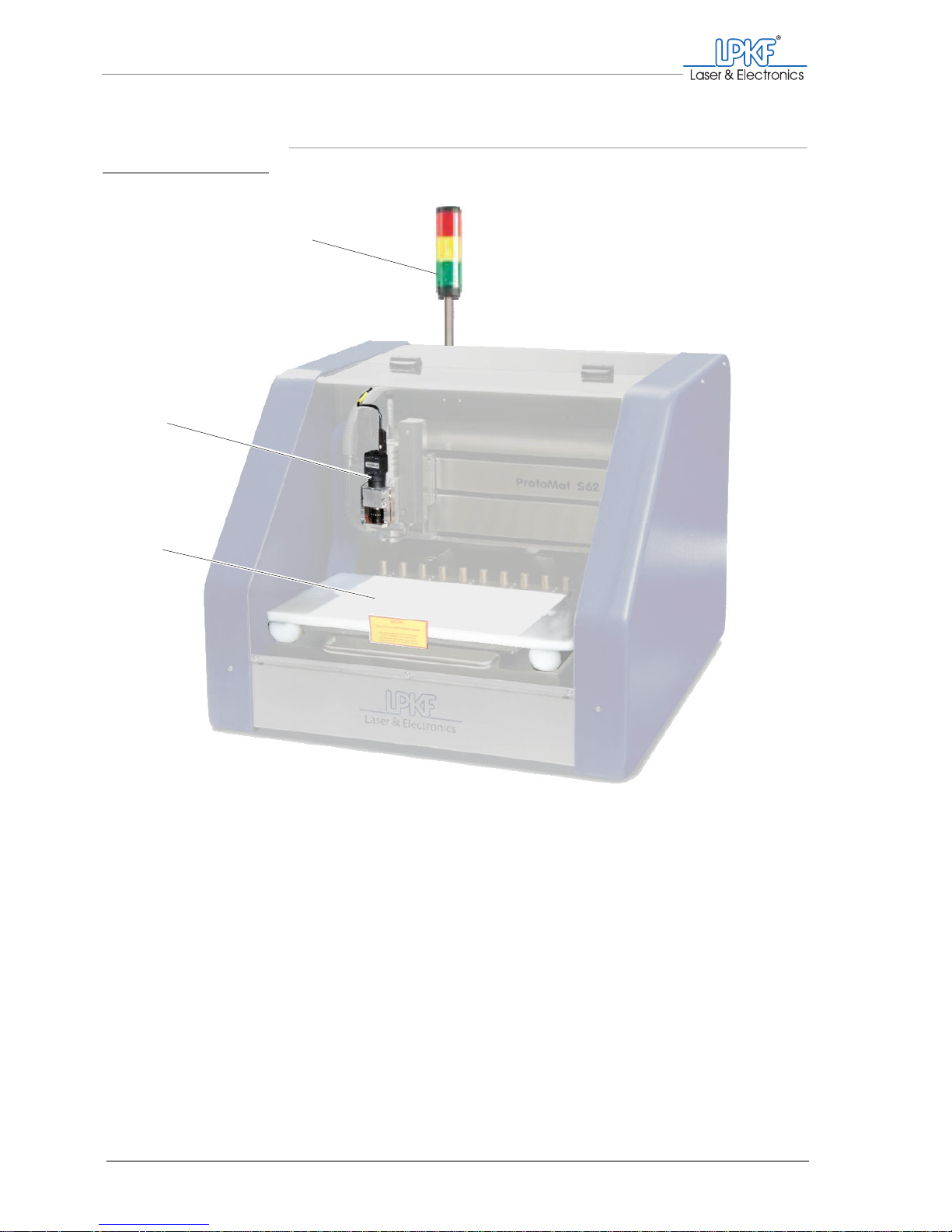
Fig. 2: Optional components
1 StatusLight 2 Camera (VisionSystem) 3 Vacuum table
1
2
3
Page 25
What is what?
Operating Manual 7.1 Rev.: 18.06.2008 23
2.2 Milling/drilling head
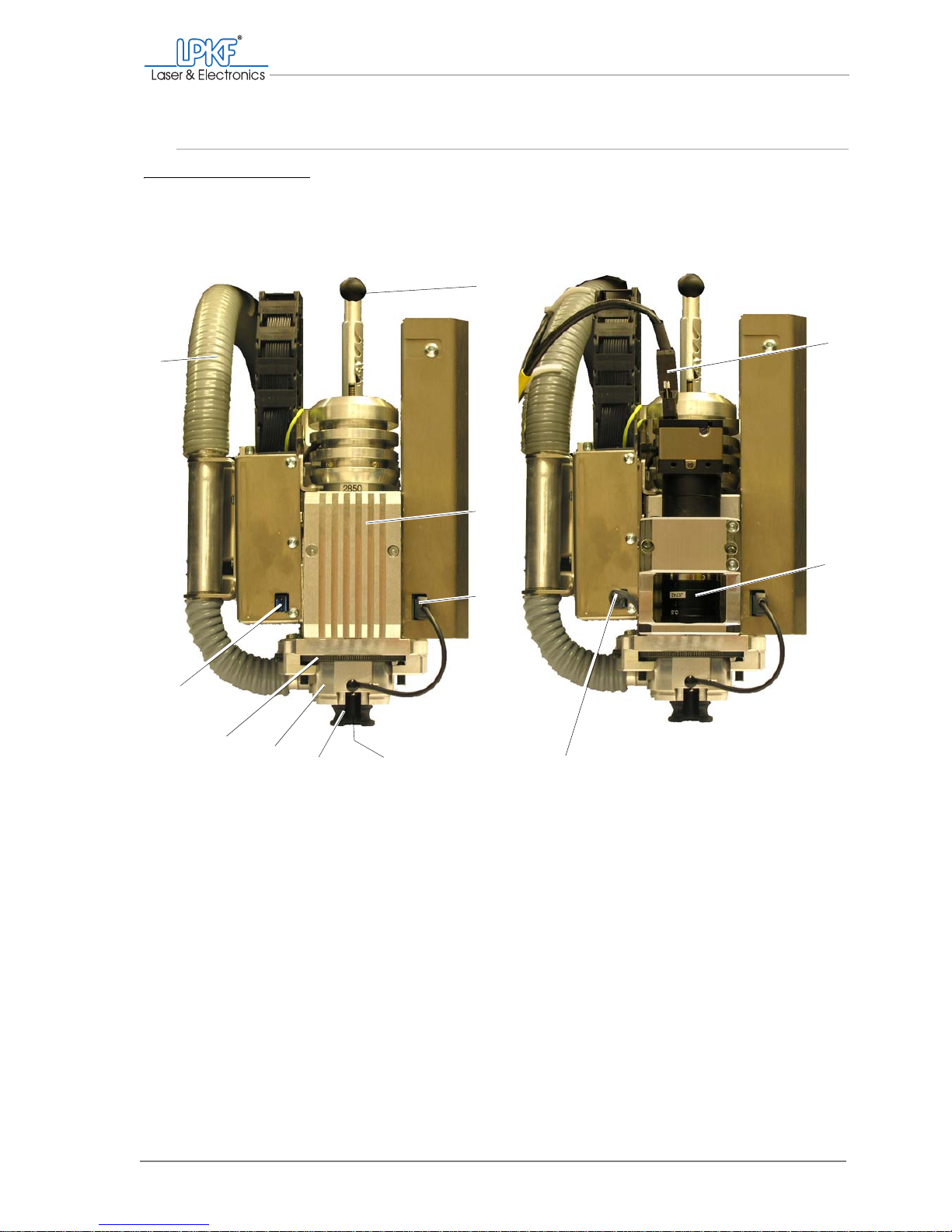
Fig. 3: Milling/drilling head (front view)
1 Spring adjustment
2 Heat sink
3 Lighting connection
4 Tool holder
5 Plastic base of the milling depth limiter,
alternatively: brush head (accessories)
6 Milling depth limiter
7 Setting wheel for milling depth limitation
8 Power supply for the camera
9 Hose for dust extraction
10 Data connection for the camera
11 Camera
12 Power supply cable for the camera
456
7
1
2
3
8
12
10
11
Basic equipment
Equipment with camera (VisionSystem)
9
Page 26
Traversing table and tool magazine
24 ProtoMat®S62
2.3 Traversing table and tool magazine
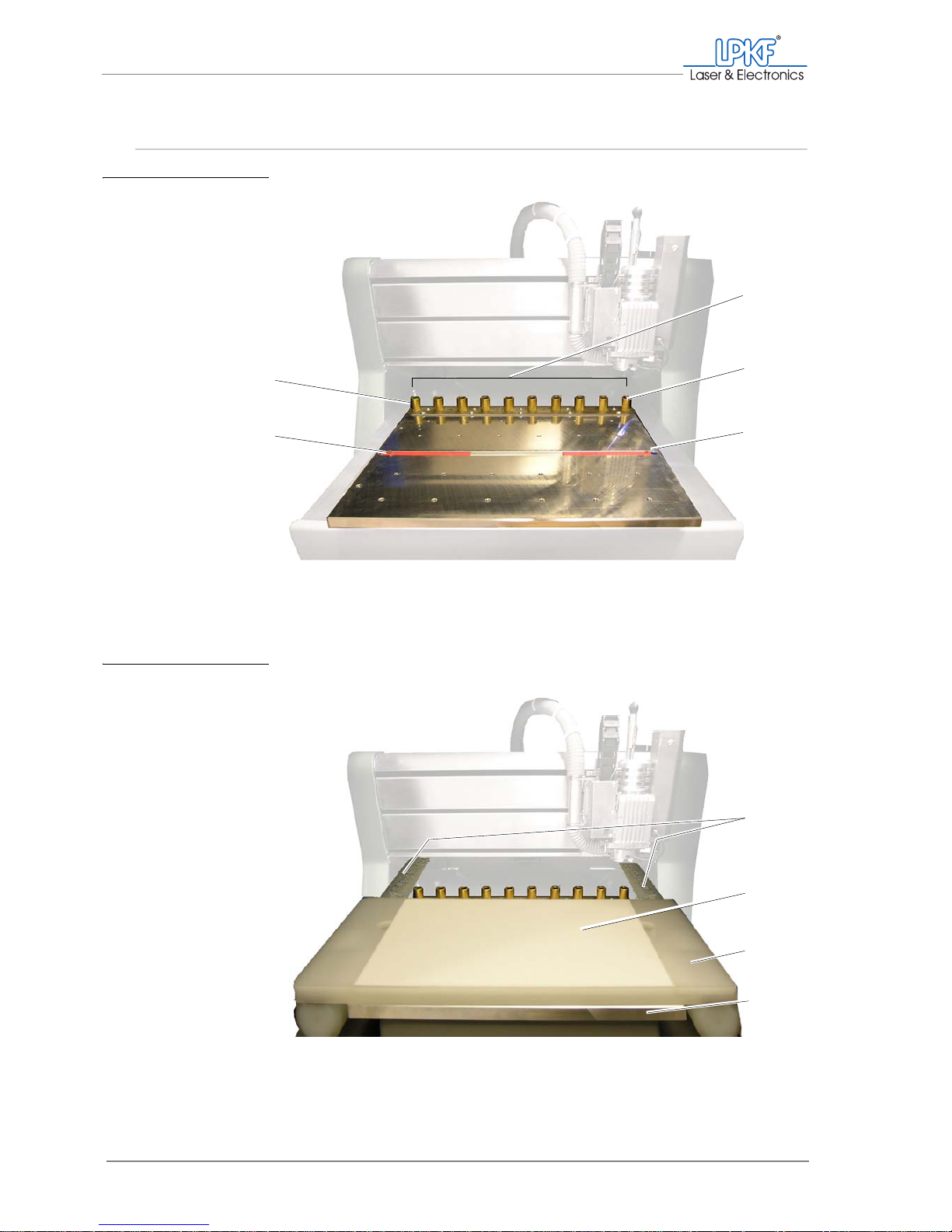
Fig. 4: Traversing table with tool magazine
1 Tool magazine
2 Tool position 10
3 Pass hole strip with pass hole pin
4 Pass hole strip with pass hole pin
5 Tool position 1
1
2
3
4
5
Fig. 5: Vacuum table (optional)
1 Extraction hoses
2 Sintered plate, permeable to air
3 Vacuum table
4 Traversing table
1
3
2
4
Page 27
What is what?
Operating Manual 7.1 Rev.: 18.06.2008 25
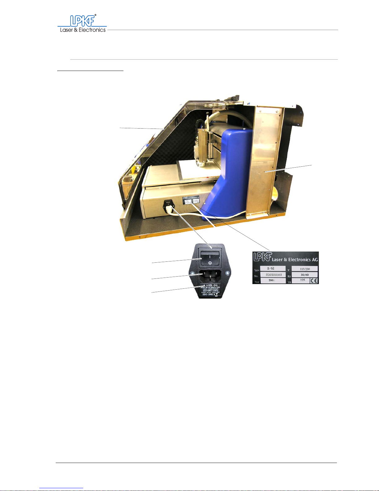
2.4 Connecting elements and rating plates
Fig. 6: Main switch with mains connection
1 Acoustic cabinet
with right side panel removed
2 Rating plate
3 Fuse holder
4 Mains connection
5 Main switch
6 Acoustic cabinet cover
1
6
2
3
4
5
Page 28
Connecting elements and rating plates
26 ProtoMat®S62
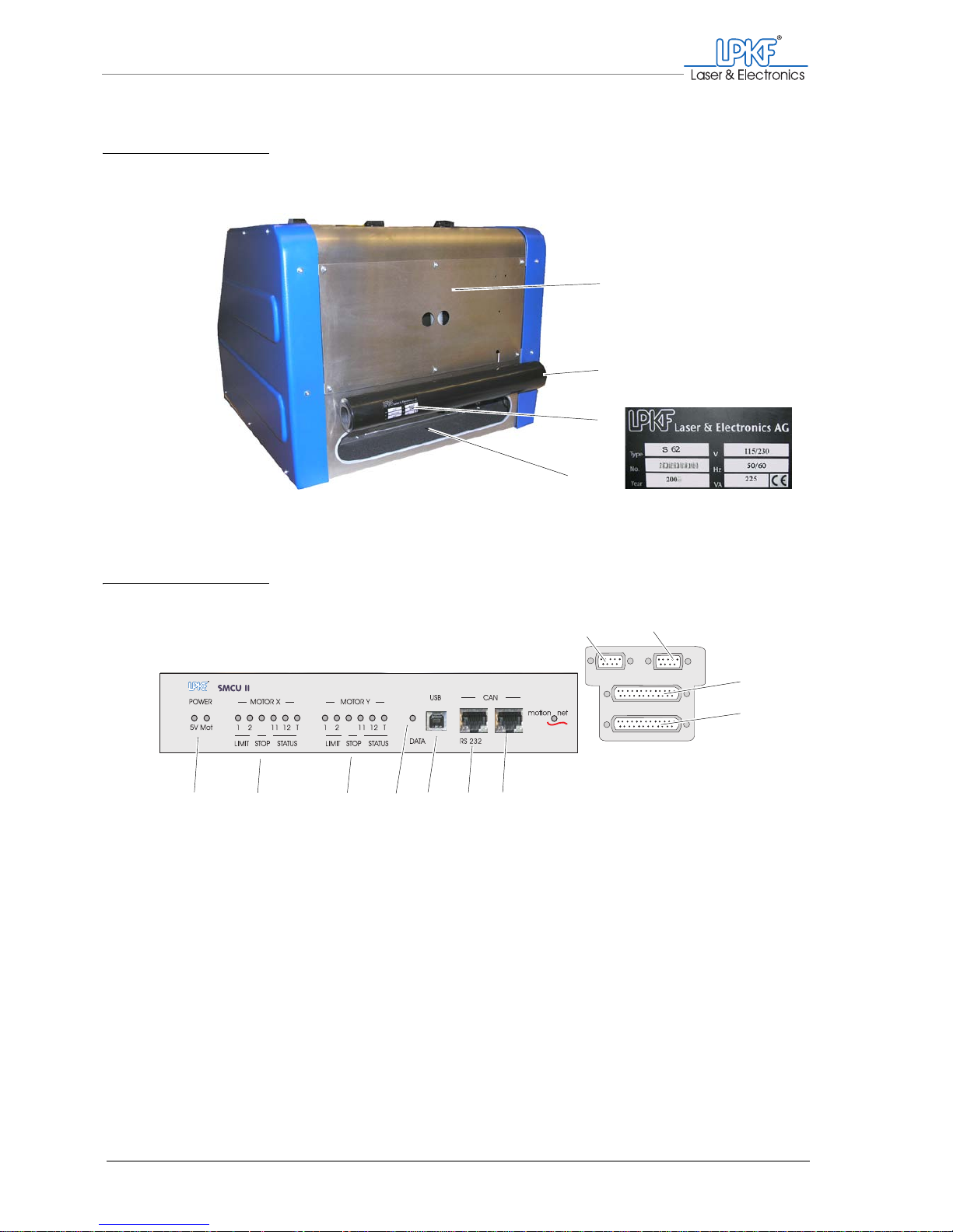
Fig. 7: Dust extraction and data connections
1 Acoustic cabinet (rear view)
2 Dust extraction
3 Rating plate
4 Control unit with data connections
1
2
3
4
Fig. 8: Control unit with data connections
1 Not used
2 StatusLight status signals (option)
3 Port 3 (dust extraction)
4 Port 4 (dust extraction)
5 RS 232
6 RS 232
7 USB (for service purposes only)
8 Data transfer indicator
9 Motor status indicator (y-axis)
10 Motor status indicator (x-axis)
11 Power indicator
(5 V electronic and motor voltage)
567891011
1
2
3
4
Page 29
What is what?
Operating Manual 7.1 Rev.: 18.06.2008 27
2.5 LPKF dust extraction
Note: The ProtoMat®S62 can be equipped with another type of dust extraction.
The relevant documentation contains information about function, operation and
maintenance.
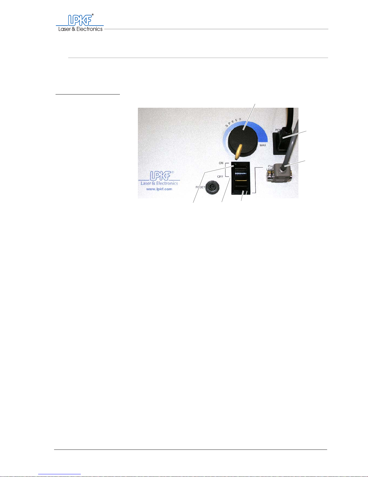
Fig. 9: LPKF dust extrac-
tion
1 Extraction force controller
2 Power supply
3 Data cable
4 Main switch in automatic mode
5 Main switch (OFF)
6 Main switch in continuous mode
1
2
3
456
Page 30

For your notes
28 ProtoMat®S62
Page 31
What you should know
Operating Manual 7.1 Rev.: 18.06.2008 29
3. What you should know
In this chapter you get to know the functions and operating elements of the ProtoMat®S62.
Prior to commencing operation, you must first familiarise yourself with the most important elements of the BoardMaster and its various operating modes.
3.1 The milling/drilling head
The milling/drilling head can be moved horizontally in the X direction only.
The traversing table must be moved in the Y direction to position the milling/drilling head in any position above the base material. The coordination of both traversing directions is controlled by BoardMaster. In the
following, this procedure will be denoted as moving the milling/drilling
head.
3.1.1 Defined positions
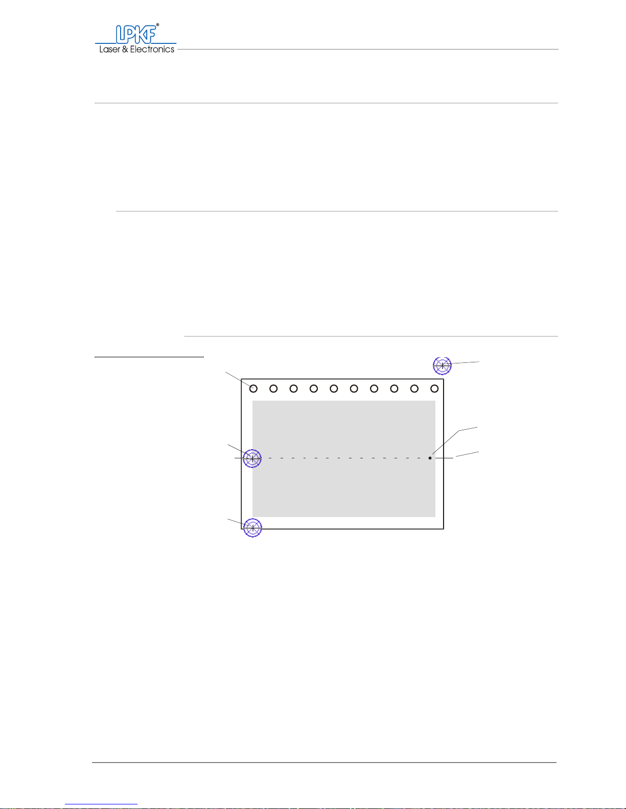
Fig. 10: Defined positions
of the milling/drilling head
1 Tool magazine
(position 1)
2 Milling/drilling head in
home position
3 Milling/drilling head in
zero position
4 Milling/drilling head in
pause position
5 Right pass hole pin
6 Mirror axis
1
2
3
4
5
6
Page 32
The milling/drilling head
30 ProtoMat®S62
Pause position In the pause position, the milling/drilling head is on the right and the tra-
versing table is at the front. Use the pause position to load the circuit
board plotter.
Home position The home position serves as the BoardMaster reference point and lies
exactly on the mirror axis of the traversing table. The milling/drilling head
is positioned exactly above the left pass hole pin; the traversing table is in
the central area.
Zero position The zero position corresponds to the zero point of the X/Y co-ordinate
system and is positioned at the front left on the traversing table. In the
zero position, the milling/drilling head is located on the left edge of the t raversing range and the traversing table is at the back.
3.1.2 Milling depth/width limitation
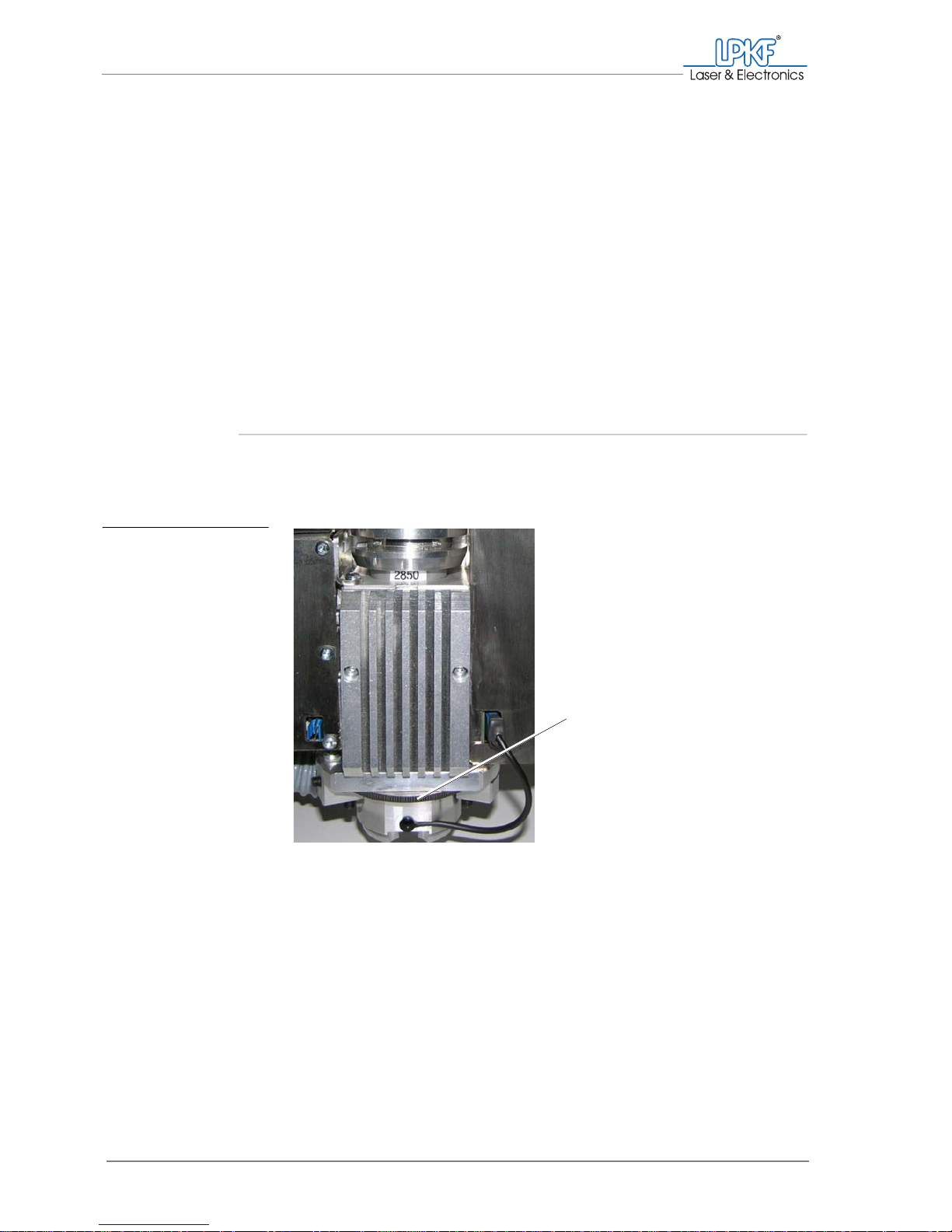
The milling depth limiter is located directly on the milling/drilling head.
The penetration depth of the surface tools can be set with the setting
wheel in order to regulate material removal.
Fig. 11: Setting wheel for
milling depth limiter
1 Setting wheel for milling depth limiter
1
Page 33
What you should know
Operating Manual 7.1 Rev.: 18.06.2008 31
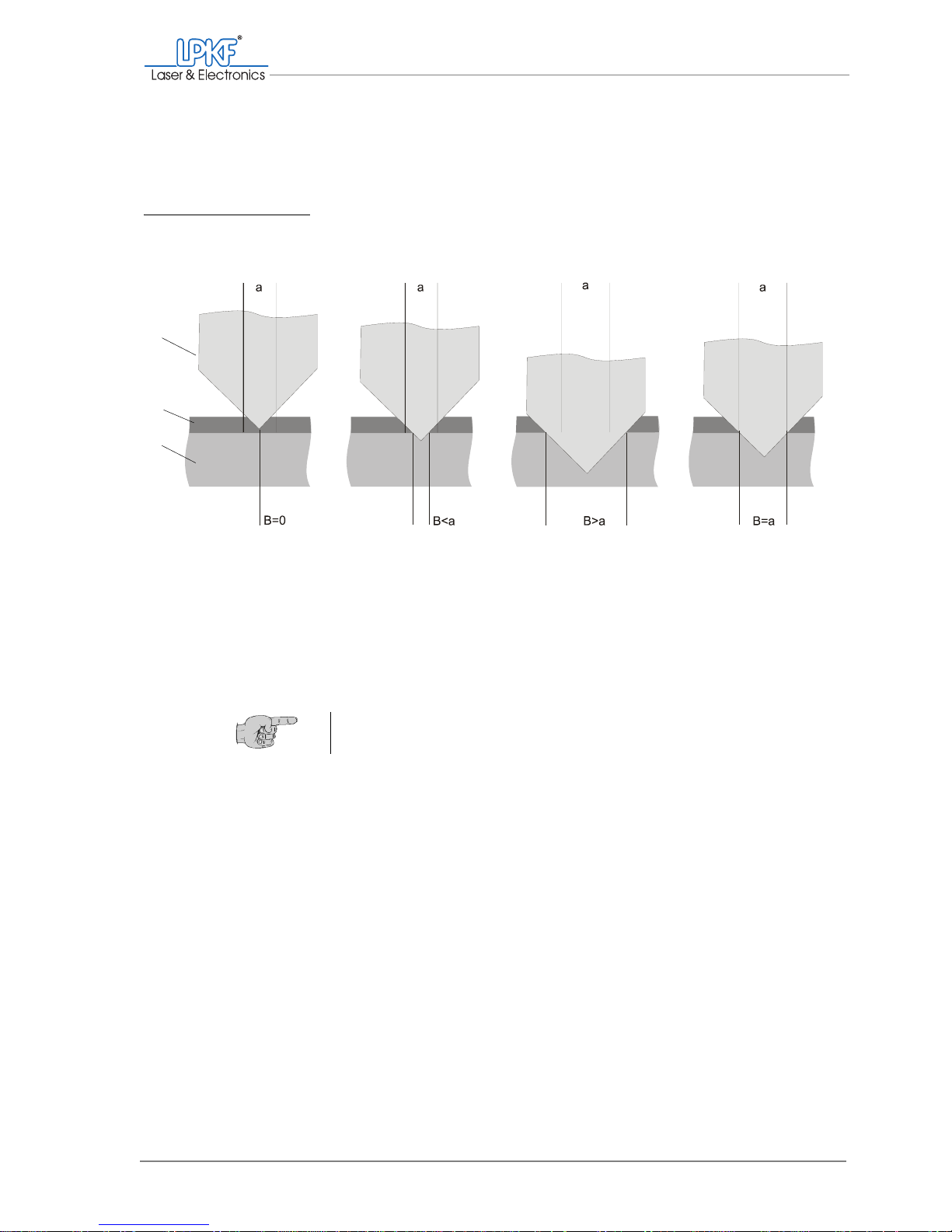
When using the conical tools Universal Cutter and Micro Cutter , you must
set the milling width to the desired size with the milling depth limiter.
Enlarge the milling depth for cutting wider milling tracks, reduce the milling depth for narrow milling tracks.
Always check the milling width at the lower edge of the (copper) laminate
to ensure the required electrical isolation between the conductor tracks.
Fig. 12: Milling width with Universal Cutter and Micro Cutter
1 Milling depth not sufficient,
no isolation
2 Milling depth too shal-
low,
milling track too narrow
3 Milling depth too deep,
milling track too wide
4 Milling depth perfect,
milling width equal to nominal
width
a - Nominal width, B - Milling width, c - Conical tool (Universal Cutter, Micro Cutter), d - (Cu) laminate, e - Carrier material
3421
c
d
e
Tip: Use the LPKF measuring microscope to check the milling width
exactly.
Page 34
The traversing table
32 ProtoMat®S62
3.2 The traversing table
The traversing table can be moved in the Y direction to position the milling/drilling head in any position above the work area. BoardMaster coordinates the traversing motions.
Note: The circuit board plotter can be equipped with the optionally availabl e vacuum table.
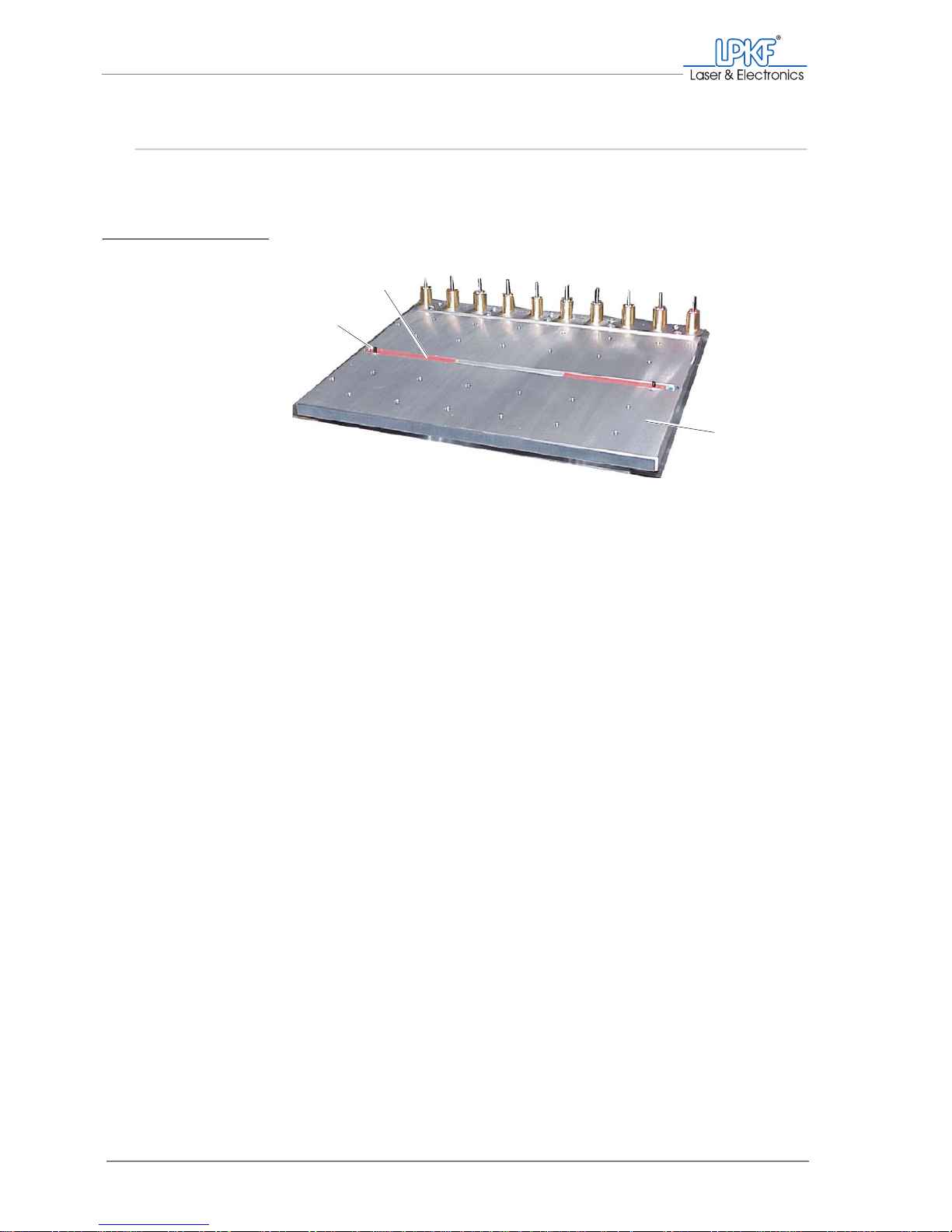
Fig. 13: Pass hole system
1 Pass hole strip (red)
2 Pass hole pin
3 Traversing table
1
2
3
Page 35
What you should know
Operating Manual 7.1 Rev.: 18.06.2008 33
3.2.1 The pass hole system
The ProtoMat®S62 is delivered from the factory with a pass hole system
for base material in standard size 9" x 12". It comprises two pass hole
pins mounted in exchangeable plastic strips. The plastic strips can be
used more than once and moved individually in the X direction. Accordingly, multiple pass hole positions can be set up for different base material sizes.
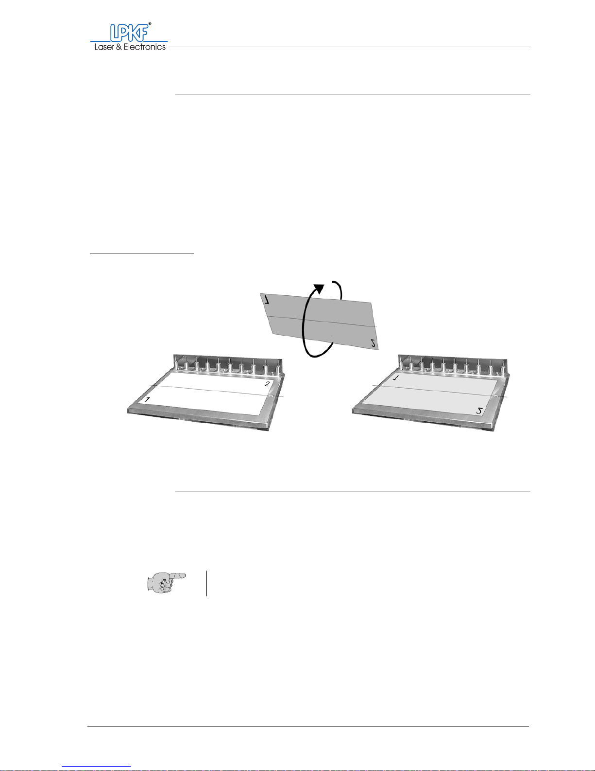
The pass hole pins mounted on the traversing table are positioned
exactly on the mirror axis of the co-ordinate system. If the base material
is turned through this (longitudinal) axis to process the second side, the
production data is automatically executed precisely to fit on the base
material.
3.2.2 Material fastening
The material must lie flat on the drilling underlay to ensure the desired
material removal rate across all areas when milling. Fasten it at the
edges using adhesive tape which will not leave any traces of residue
when removed.
Fig. 14: Turning the material through the mirror axis
Tip: For flexible materials use the optional vacuum table to fasten the
material in a perfectly flat position.
Page 36
The tool magazine
34 ProtoMat®S62
3.3 The tool magazine
The tool magazine is located on the traversing table and can be loaded
with up to 10 tools. The tool holder (positions) are numbered from left to
right.
Loading The tools must be inserted into the tool holder as far as they will go with
the tip pointing downwards and according to the tool position indicated in
BoardMaster. This facilitates (semi-)automatic taking up and putting
down.
3.4 Usable tools
The ProtoMat®S62 has been designed exclusively for the use of LPKF
drilling and milling tools manufactured specifically and equipped with
spacer rings. If other tools are used, we cannot guarante e that the circuit
board plotter will function without errors, nor can we be held liable for
working results.
The tools are subdivided into two main groups:
• Surface tools with 36 mm (1.42") total length (Cutters and End Mills)
• Penetrative tools with a total length of 38 mm (Spiral Drills, Contour
Routers and End Mills long).
The numbers on the spacer rings indicate the tool diameter.
Fig. 15: Tool positions
1 Tool position 1 2 Tool position 10
1
2
Page 37
What you should know
Operating Manual 7.1 Rev.: 18.06.2008 35
3.4.1 Surface tools
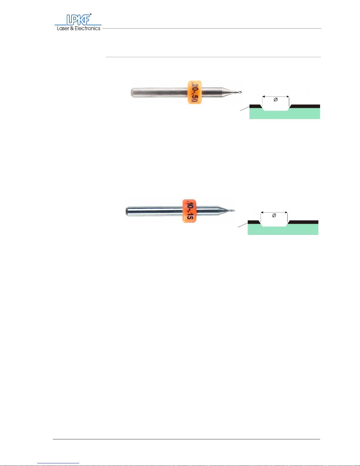
Universal Cutter 1/8"
Micro Cutter 1/8"
Application:
Milling insulation clearances of varying widths in copper-plated base material. Use the milling depth setting
to define the milling width.
Colour:
Orange
Shape:
Conical
Milling widths:
0.2 mm – 0.5 mm (8 mil – 20 mil), variably adjustable
via penetration depth
0.2 - 0.5 mm
(8 - 20 mil)
Copper
Application
Fine insulation clearances with copper layer 18 µm
thick. Use the milling depth setting to define the milling
width.
Colour:
Orange
Shape:
Conical
Milling widths:
0.1 mm – 0.15 mm (4 mil – 6 mil), variably adjustable
via penetration depth
0.1 - 0.15 mm
(4 - 6 mil)
Copper
Page 38
Usable tools
36 ProtoMat®S62
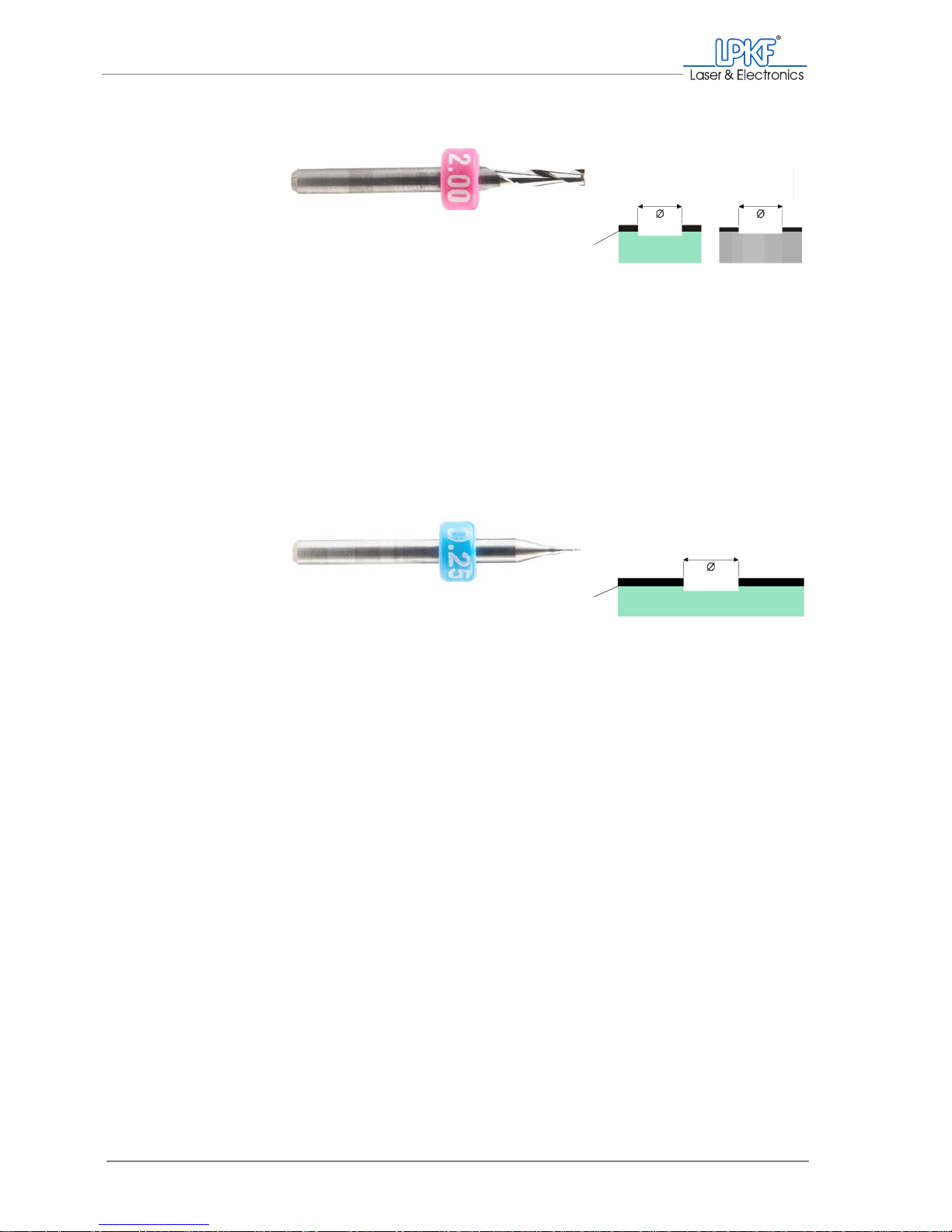
End Mill (End Mill 1/8")
RF end mill (End Mill (RF)
1/8")
Application:
Aluminium engraving, recesses and wide insulation clearances
Colour:
Purple
Shape:
Cylindrical
Milling widths:
d = 0.80 mm (31 mil)
d = 1.00 mm (39 mil)
d = 2.00 mm (79 mil)
d = 3.00 mm (118 mil)
0.8-3.0mm
(31-118mil)
Copper
0.8-3.0mm
(31-118mil)
Aluminium
Application:
Smallest insulation clearances in RF materials.
Colour:
Blue
Shape:
Cylindrical
Milling widths:
d = 0.15 mm (6 mil)
d = 0.25 mm (10 mil)
d = 0.4 mm (16 mil)
0.5-0.4mm
(6 - 16 mil)
Copper
Page 39
What you should know
Operating Manual 7.1 Rev.: 18.06.2008 37
3.4.2 Penetrative tools
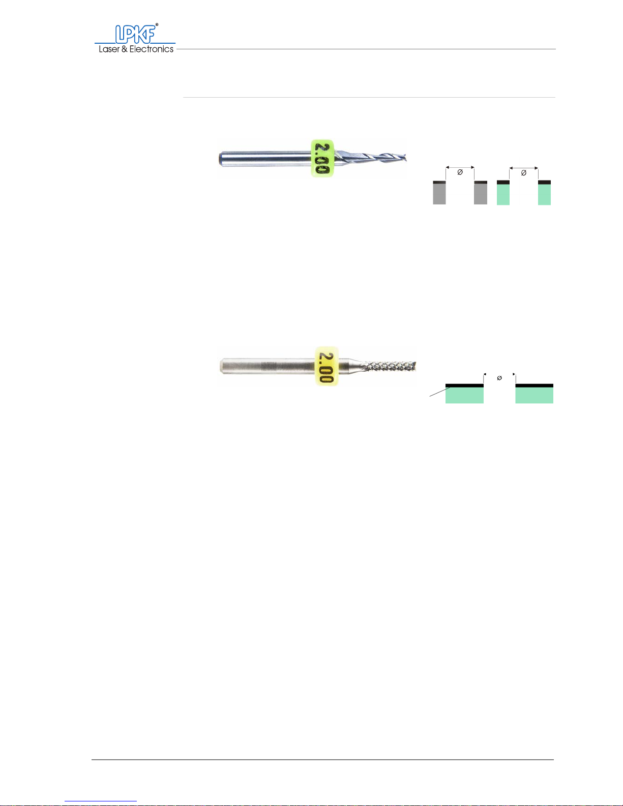
End mill long (End Mill
long 1/8")
)
Contour router
(Contour Router)
Application:
Contour milling, material cut-outs and dep anelisation in
aluminium and soft RF and microwave materials.
Colour:
Light green
Shape:
Cylindrical
Milling widths:
d = 1.00 mm (39 mil)
d = 2.00 mm (79 mil)
1-2mm
(39 - 79 mil)
Aluminium
1-2mm
(39 - 79 mil)
Dielectric
Application:
Contour milling, material cut-outs, depanelisation,
bores >2.4 mm/> 3.0 mm.
Colour:
Yellow
Shape:
Cylindrical
Milling widths:
d = 1.0 mm (39 mil)
d = 2.0 mm (79 mil)
1-2mm
(39 - 79 mil)
Copper
Page 40
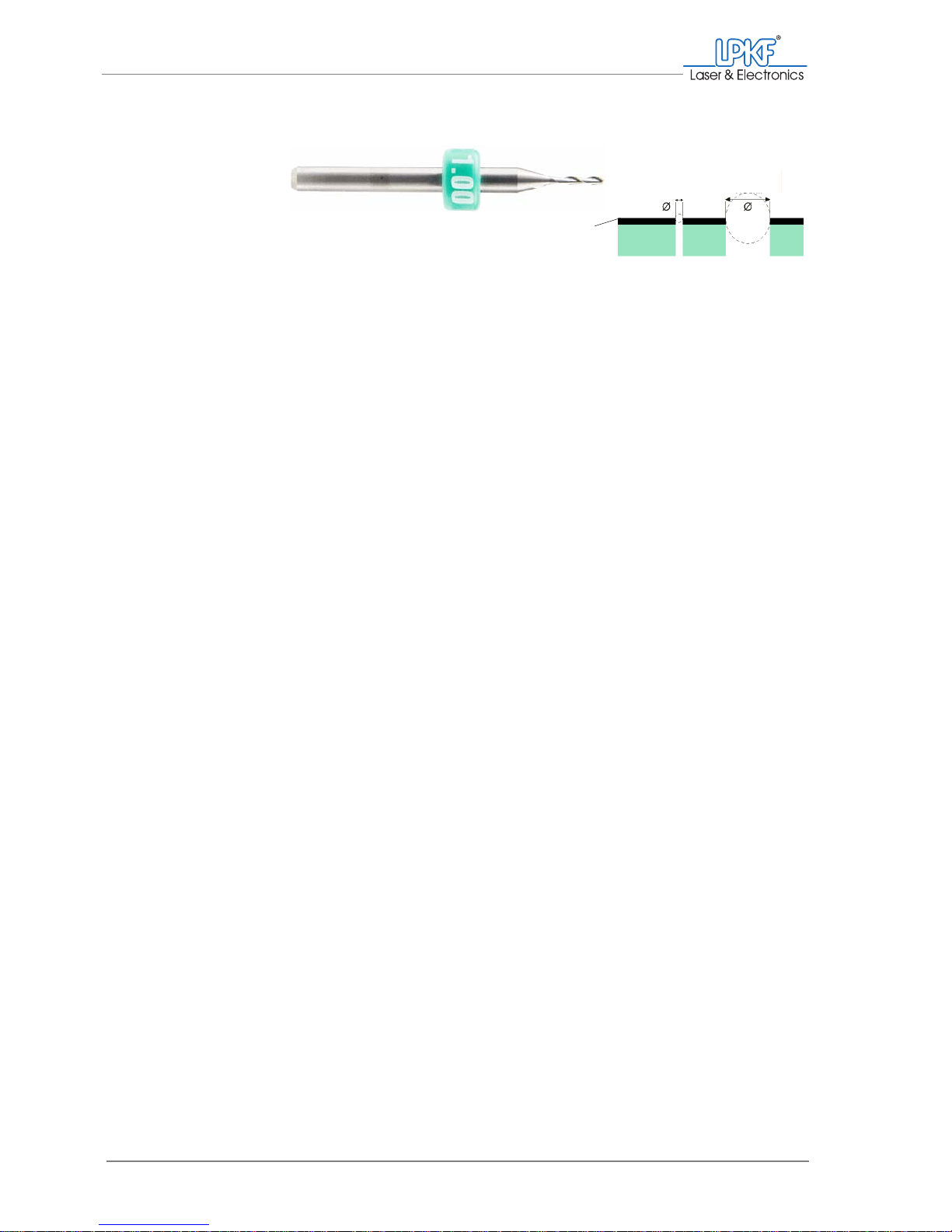
Usable tools
38 ProtoMat®S62
Drill (Spiral Drill)
Application:
Bores penetrating the material.
Colour:
Green
Shape:
Cylindrical
Available diameters:
0.20 mm (8 mil)
0.30 mm (12 mil)
0.40 mm (16 mil)
0.50 mm (20 mil)
0.60 mm (24 mil)
0.70 mm (28 mil)
0.80 mm (31 mil)
0.85 mm (33 mil)
0.90 mm (35 mil)
1.00 mm (39 mil)
1.10 mm (43 mil)
1.20 mm (47 mil)
1.30 mm (51 mil)
1.40 mm (55 mil)
1.50 mm (59 mil)
1.60 mm (63 mil)
1.70 mm (67 mil)
1.80 mm (71 mil)
1.90 mm (75 mil)
2.00 mm (79 mil)
2.10 mm (83 mil)
2.20 mm (87 mil)
2.30 mm (91 mil)
2.40 mm (94 mil)
2.95 mm (116 mil)
3.00 mm (118 mil)
min. 0.2 mm
(8 mil)
Copper
max. 3.0 mm
(118mil)
Page 41

What you should know
Operating Manual 7.1 Rev.: 18.06.2008 39
3.5 The 2.5 D function
With its software-controlled 2.5 D function, the ProtoMat®S62 is perfect
for milling contours and cut-outs in thickwalled housing materials that
make high material removals necessary. The material is removed in several cycles to protect the tool.
You can also mill stepped crevices, for example component pockets for
SMD loading, with the 2.5 D function.
Required accessories You will need the vacuum table (which can be purchased as an acces-
sory) to guarantee an exactly flat position when performing 2.5 D surface
milling. Contour/cut-out milling can also be performed with the basic
equipment in 2.5 D mode.
For optimum dust extraction, the milling depth limiter base must be
replaced with the LPKF brush head (which is available as an accessory)
when processing in 2.5 D mode (see chapter ‚ "Dismounting the plastic
base/brush head", on page 62).
Usable tools It is only possible to use the End Mill long 1/8" and the Contour Router in
2.5 D processing. The End Mill (RF) 1/8" is not suitable for the
2.5 D function.
Fig. 16: 2,5 D processing (application examples))
1 Deep milling in multiple
cycles
2 Contour milling in multiple
cycles
3 Stage milling in two cycles 4 Multi-stage milling with different
tool diameters
a - Milling cycle, b - Material
12 34
a
b
Page 42

Manual operation
40 ProtoMat®S62
Use For tool-friendly material removal/contour milling, the 2.5 D function
should be used with the following materials/milling depths:
Tab. 1: 2.5 D processi ng, milling depth and materials
3.6 Manual operation
The manual operation is used primarily for creating individual bores and
structures, for post-processing printed circuit boards manufactured automatically and for special applications.
Manual operation supplements the automatic functions and can be executed at any time.
Material Milling depth
GFK (FR4)/CFK base material
PTFE/ceramic composite base material
>2mm
Wood
Non-ferrous metals (aluminium, brass)
>0.25mm
Plastics (polyoxymethylenes, ABS copolymers
Page 43
What you should know
Operating Manual 7.1 Rev.: 18.06.2008 41
3.7 Automatic operation
In automatic mode, the CAD data prepared with CircuitCAM is used for
production. These *.LMD files contain information regarding layout, structure and use of the required tools.
3.7.1 Production types and phase files
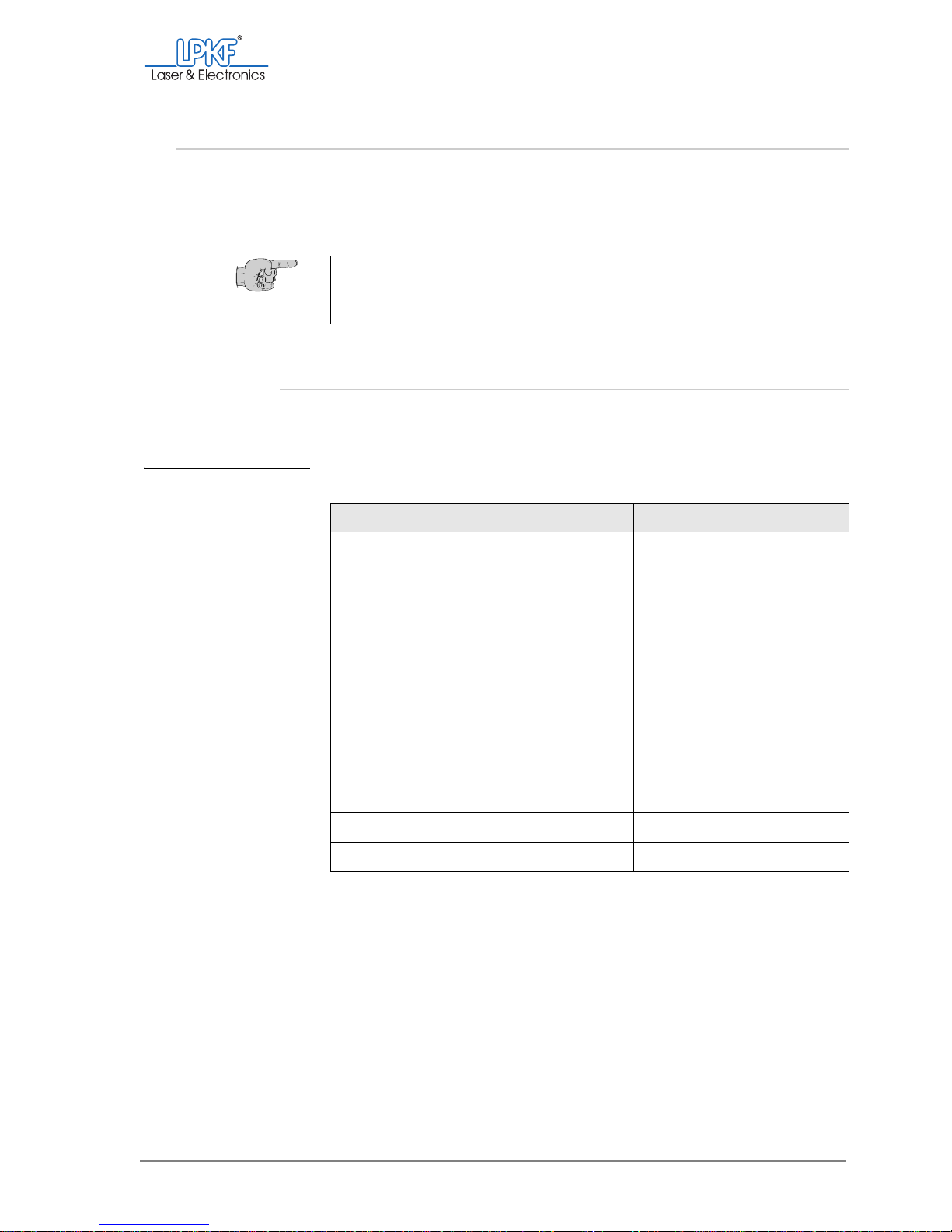
The following production types can be produced using the phase files
included in the scope of delivery:
Tab. 2: Production types and phase files
As the ProtoMat®S62 is factory-set to produce single-sided/double-sided
printed circuit boards followed by galvanic through-hole plating, it is not
necessary to select a phase file for this production type. Phase file
1-2layer.phs (<default>) is used.
Tip: Use the tutorial files prepared by LPKF to familiarise yourself with
the automatic operation and to produce a double-sided sample circuit
board. Detailed information about the tutor data can be found in the
tutorial ProtoMat
®
S62 Tutor data.
Production type Phase file
Single-sided/double-sided printed circuit
boards
(galvanic through-hole plating)
1-2layer.phs (<default>)
Single-sided/double-sided printed circuit
boards
(galvanic through-hole plating with LPKF
ProConduct)
1-2layer + proconduct.phs
4-layer multi-layer
(galvanic through-hole plating)
4-layer.phs
4-layer multi-layer
(galvanic through-hole plating with LPKF
ProConduct)
4-layer + proconduct.phs
6-layer multi-layer 6-layer.phs
Solder stop foils soldermask.phs
Solder paste stencils stencilmilling.phs
Page 44
Automatic operation
42 ProtoMat®S62
Automatic production takes place phase-by-phase, whereby each production phase must be started manually. The production phases should
always be carried out one after the other in the order specified. Individual
production phases can be skipped and/or executed at a later time. Note,
however, that some work step s are based on previous production pha ses
which cannot be executed afterwards.
You can create additional phase files for your individual applications
and/or reconfigure existing ones. Please see the BoardMaster manual for
information.
3.7.2 Production phases
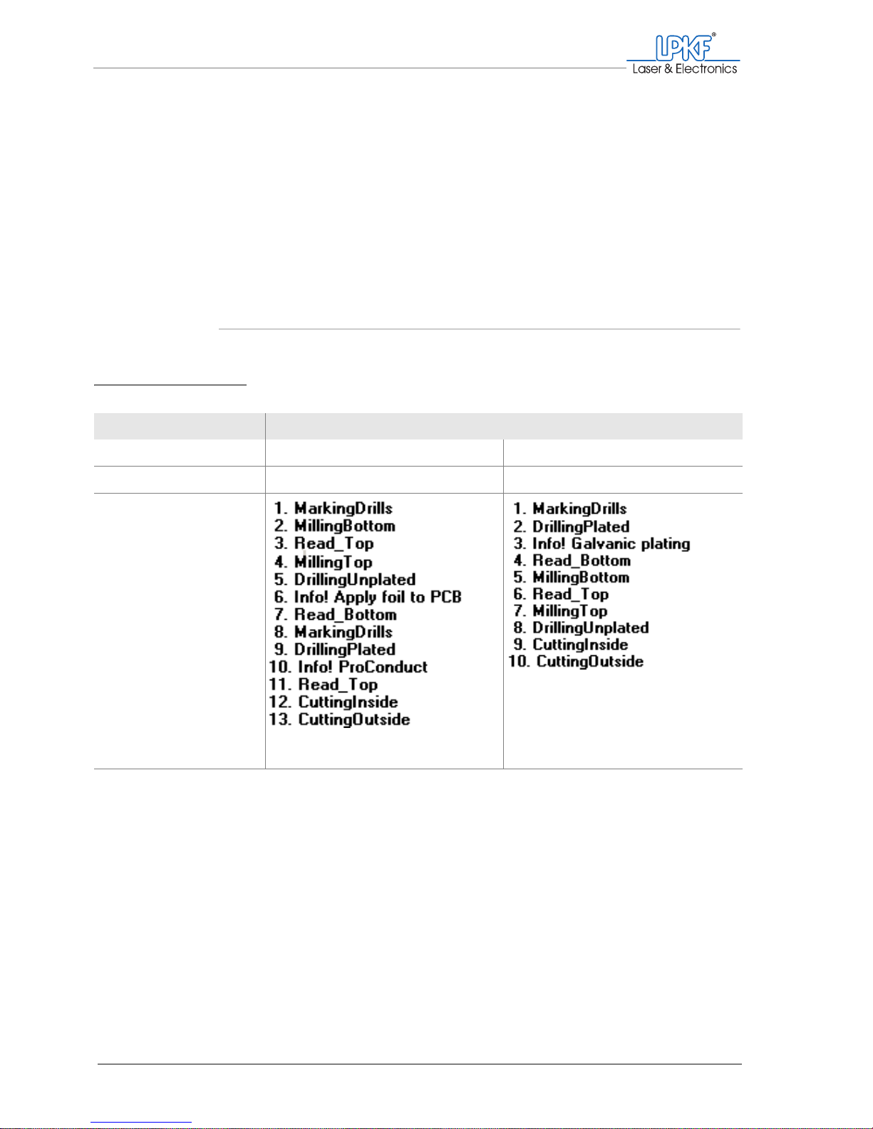
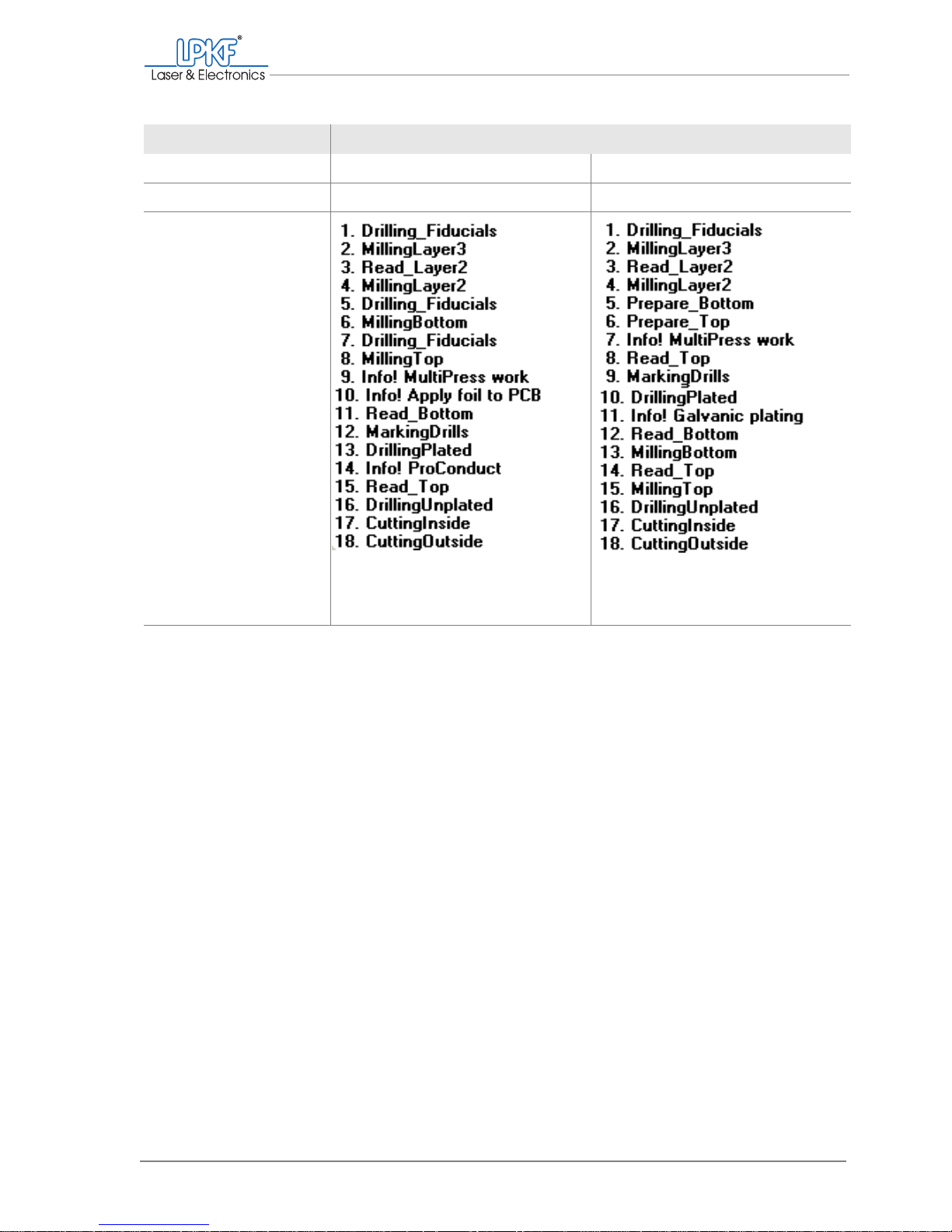
The following production phases are contained in the phase files:
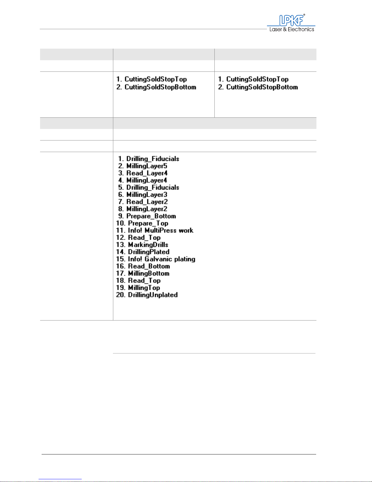
Tab. 3: Production phases
1/2-layer printed circuit boards
Plating LPKF ProConduct Galvanic
Required phase file 1-2layer + proconduct.phs 1-2layer.phs (<default>)
Production phases
(Page 1 of 3)
Page 45
What you should know
Operating Manual 7.1 Rev.: 18.06.2008 43
4-layer printed circuit boards
Plating LPKF ProConduct Galvanic
Required phase file 4layer + proconduct.phs 4layer.phs
Production phases
(Page 2 of 3)
Page 46
Automatic operation
44 ProtoMat®S62
Work steps in the production phases
BoardMaster assists you in selecting the next production phase and provides information about the manual operating steps required for production, for example for turning the base material or pressing the individual
layers externally before continuing processing with the ProtoMat
®
S62.
A production phase must always be selected and st arted manually. It can
be stopped at any time and resumed later. Accordingly, you can check
quality, correct the milling depth/width or change tools during production.
The production phases comprise the following work steps that are processed efficiently one after the other:
Solder stop foils Solder paste templates
Required phase file soldermask.phs stencilmilling.phs
Production phases
6-layer printed circuit boards
Plating Galvanic
Required phase file 6layer.phs
Production phases
(Page 3 of 3)
Page 47

For your notes
45 ProtoMat®S62
Tab. 4: Work steps in production phases
Production phase Work steps Processed material side
MarkingDrills Centre-punching bores
Drilling pass holes
Bottom
Read_Top Reading in pass holes
(only with VisionSystem)
Top
Read_Bottom Reading in pass holes
(only with VisionSystem)
Bottom
DrillingPlated Drilling holes for plating Bottom
DrillingUnplated Drilling mounting holes
(not for plating)
Top
MillingTop Milling Top
MillingBottom Milling Bottom
Info! Galvanic plating galvanic through-hole plating
(external with galvanic station)
All layers
Info! ProConduct Plating with the LPKF ProConduct
system
All layers
Info! MultiPress_work Pressing multiple layers with external
multi-layer press
All layers
Info! Apply foil to PCB Protective foil ProConduct Top and bottom
CuttingInside Milling internal cut-outs Top
CuttingOutside Milling contours Top
Read_Layer2
Read_Layer3
Read_Layer4
Reading in pass holes
(only with VisionSystem)
Top/bottom
Prepare_Top
Prepare_Bottom
Preparing outer layers for pressing,
drilling pass hole exemptions
(only with galvanically plated multi-layers)
Top/bottom
Page 48

Automatic operation
46 ProtoMat®S62
3.7.3 Data selection
Production only ever runs with the data you have activated.
You can use the selection functions to activate all data or select and acti-
vate subsections, individual lines or even individual segments of a line.
It is also possible to restrict the selection to one or more tools within a
production phase. Thus, for example, you can start by drilling only holes
with a selected diameter or cutting milling tracks with a certain width.
The data must be selected and reactivated for each production phase. If
no data is activated, BoardMaster considers the selected production
phase at the start as completed and no processing will be executed.
Page 49
Manual tasks and settings
Operating Manual 7.1 Rev.: 18.06.2008 47
4. Manual tasks and settings
This chapter contains essential information about manual operation of the ProtoMat®S62. You
will find detailed information about the automatic control and operation of the LPKF BoardMaster software in the BoardMaster manual. Observe the safety instructions and follow the guidances step by step in order to achieve the desired result.
Y
4.1 Switching on the system
To avoid unnecessary error messages you always should switch on the
system in the specified order.
In the following we assume that the computer is switched on and the
operating system has been started.
Note: If your ProtoMat®S62 is equipped with different dust extraction, familiarise yourself with the relevant information on setting options.
WARNING
Risk of injury!
When opened, the cover of the acoustic cabinet can drop down
due to impact shocks or vibrations. This can result in limbs being
broken or crushed.
› When opening the cover of the acoustic cabinet make sure that
it engages in the uppermost position and cannot drop down as
a result of vibrations or the influence of third parties.
Page 50
Switching on the system
48 ProtoMat®S62
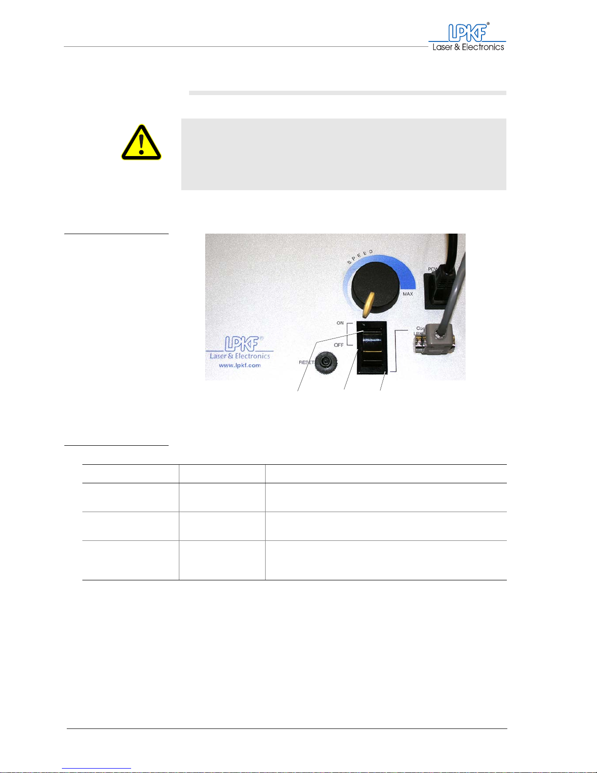
I. Switching on the LPKF dust extraction (optional)
1. Switch the main switch of the LPKF dust extraction to the desired
position.
Tab. 5: Operating modes of the LPKF dust extraction:
[ ] The set operation mode will be used.
WARNING
Health hazard!
Fine dusts and gases hazardous to your health can emerge dur-
ing material processing.
› Make sure that the dust extraction for material processing is
switched on (continuous or automatic operating mode).
Fig. 17: Dust extraction -
operating modes
1 Continuous operating mode 2 Off 3 Automatic mode
Setting Operating mode Operation
ON Continuous operat-
ing mode
Continuous extraction,
Switching On/Off using the BoardMaster is not possible
OFF Off No extraction,
Switching On/Off using the BoardMaster is not possible
Connection to
LPKF ProtoMat
Automatic mode The extraction starts automatically with the milling/drilling
motor, manual switching On/Off using the BoardMaster is
possible.
1
23
Page 51
Manual tasks and settings
Operating Manual 7.1 Rev.: 18.06.2008 49
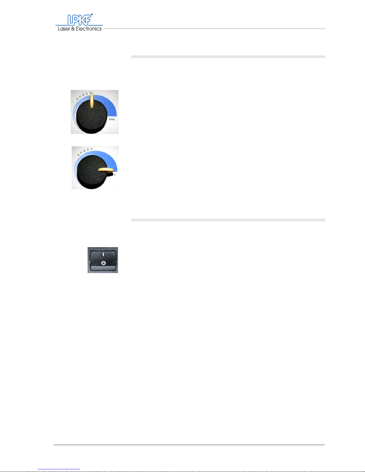
II. Setting the suction force (optional)
1. Turn the Speed controller to select the desired suction force. For
the optimum operation with low noise pollution we recommend the
following settings:
– Basic equipment (without vacuum table):
Turn the Speed controller to the medium range.
– For operation with vacuum table (optional):
Turn the Speed controller to the position Max.
[ ] The dust extraction is ready for operation.
III. Switching on the circuit board plotter
1. Make sure that there are no objects on the traversing/vacuum table
of the circuit board plotter.
2. Switch the main switch of the ProtoMat
®
S62 to the position I.
Note: The main switch is located on the right side of the circuit board plotter (if necessary, inside of the acoustic cabinet).
The lighting of the milling/drilling head is on.
3. Close the the acoustic cabinet cover.
Note: With opened cover the data communication to the computer is interrupted and the circuit board plotter can not be controlled by BoardMaster.
[ ] The circuit board plotter is switched on.
Page 52
Switching on the system
50 ProtoMat®S62
IV. Starting BoardMaster
1. Double click on the BoardMaster symbol on the desktop.
Make sure that you start the current BoardMaster version.
or:
Click on Start > Programs > LPKF Laser & Electronics >
BoardMaster ...
Note: Make sure to start the BoardMaster version delivered with the
ProtoMat
®
S62 circuit board plotter.
2. If the window Connect... appears:
– Ensure the correct connection settings (see "Checking the con-
nection settings (if necessary)" on page 51).
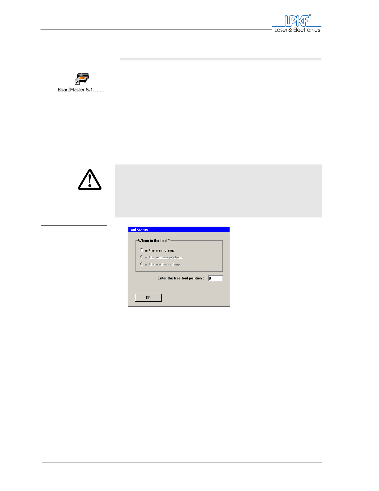
3. If there is already a tool in the circuit board plotter:
– Enter the corresponding position in the box Where is the tool ?.
– Enter the number of any free tool position in the field Enter the
free tool position:.
CAUTION
Machine damage caused by wrong operation.
The milling/drilling head, tool magazine and tools can collide
and become damaged if a wrong position is given.
› Make sure that the tool positions activated in the dialog
window correspond to those specified in the circuit board
plotter.
Fig. 18: Dialog box
Tool status
Page 53
Manual tasks and settings
Operating Manual 7.1 Rev.: 18.06.2008 51
4. If there is no tool in the circuit board plotter:
– Deactivate all entries.
– Enter the value 0 in the field Enter the free tool position:.
5. Click on OK.
[ ] The ProtoMat®S62 is ready for operation.
V. Checking the connection settings (if necessary)
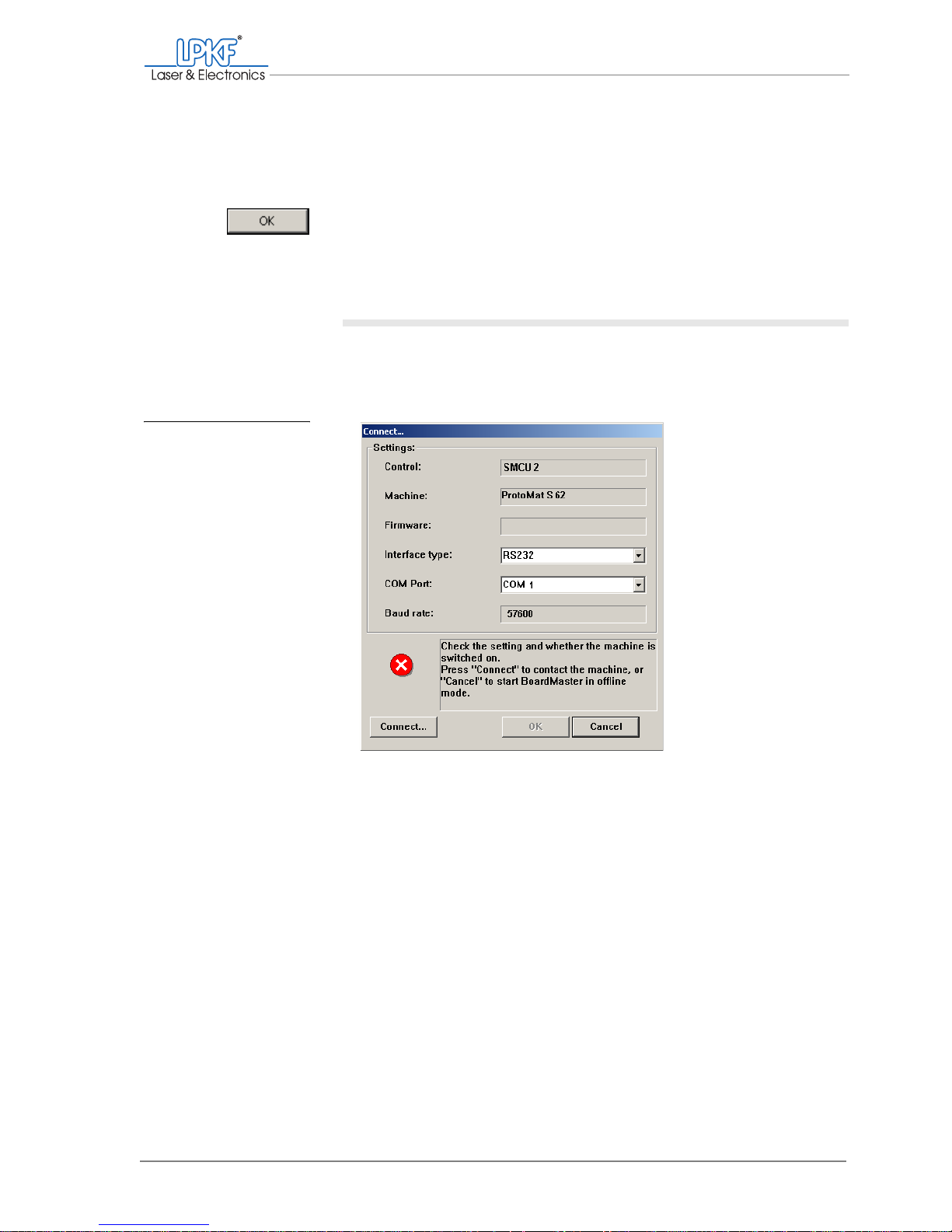
If the circuit board plotter is not recognised automatically, the input window Connect... appears. If necessary, you have to change the connec-
tion settings.
1. Make sure that the circuit board plotter is switched on and that the
milling/drilling head lighting is on.
Fig. 19: Input window Con-
nect...
Page 54
Switching off the system
52 ProtoMat®S62
2. Make sure that the following values are entered:
3. Check the settings of the Windows system control
(see ProtoMat
®
S62 Installation Manual)
4. Click on Connect....
As soon as the connection to the circuit board plotter can be established,
the BoardMaster user interface appears.
5. If the Connect... window opens repeatedly:
Check the settings in the Windows system configuration (see "Configuring the COM port" on page 29)
Note: If you click on Cancel BoardMaster will be opened, but the circuit
board plotter cannot be activated.
[ ] The BoardMaster user interface will be opened (see figure 20 on page 54).
4.2 Switching off the system
To switch off the ProtoMat®S62, quit the BoardMaster first and then
switch off the circuit board plotter and the computer.
I.
Quitting BoardMaster
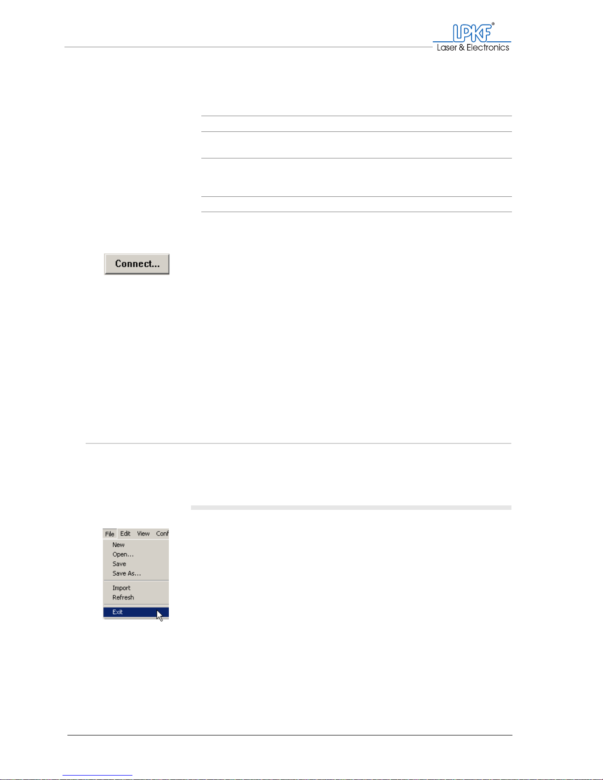
1. Click on File > Exit.
The message "Do you want to move the milling/drilling head to the refer-
ence point?" appears.
Control: SMCU 2
Machine: ProtoMat S62
Interface type: RS-232
(USB is only intended for service purposes)
COM Port: COM port to which the circuit board plotter is
connected and which was defined in the
Windows system control.
Baud rate: 57600
Page 55
Manual tasks and settings
Operating Manual 7.1 Rev.: 18.06.2008 53
2. Click on Yes.
The milling/drilling head and the working table will move to the Zero position.
Note: If you click on No, the Zero position must be reinitialized at the next
start, which is time-consuming.
[ ] Now you can switch off the circuit board plotter and, if necessary, the dust
extraction.
II. Switching off the circuit board plotter
1. Switch the main switch on the circuit board plotter (in the acoustic
cabinet) to the position 0.
The lighting of the milling/drilling head goes out.
[ ] Now you can switch off the dust extraction and shut down the computer.
III. Switching off the LPKF dust extraction
The LPKF dust extraction must be switched off manually only if it is
used in continuous operating mode. During the automatic operating
mode it is switched off automatically together with the circuit board plotter.
If your ProtoMat
®
S62 is equipped with another dust extraction, famil-
iarise yourself with the relevant operation information.
1. Set the main switch of the LPKF dust extraction to the position OFF
(centre position).
or:
Set the main switch of the LPKF dust extraction to the position
Connection to LPKF ProtoMat, to use the dust extraction after
the next start ProtoMat
®
S62 in the automatic operating mode.
[ ] The LPKF dust extraction is switched off.
Page 56
Finding out about BoardMaster
54 ProtoMat®S62
4.3 Finding out about BoardMaster
The ProtoMat®S62 is controlled by means of the LPKF Software
BoardMaster. In the following the user interface and the most important
selection and control elements will be explained.
4.3.1 The user interface
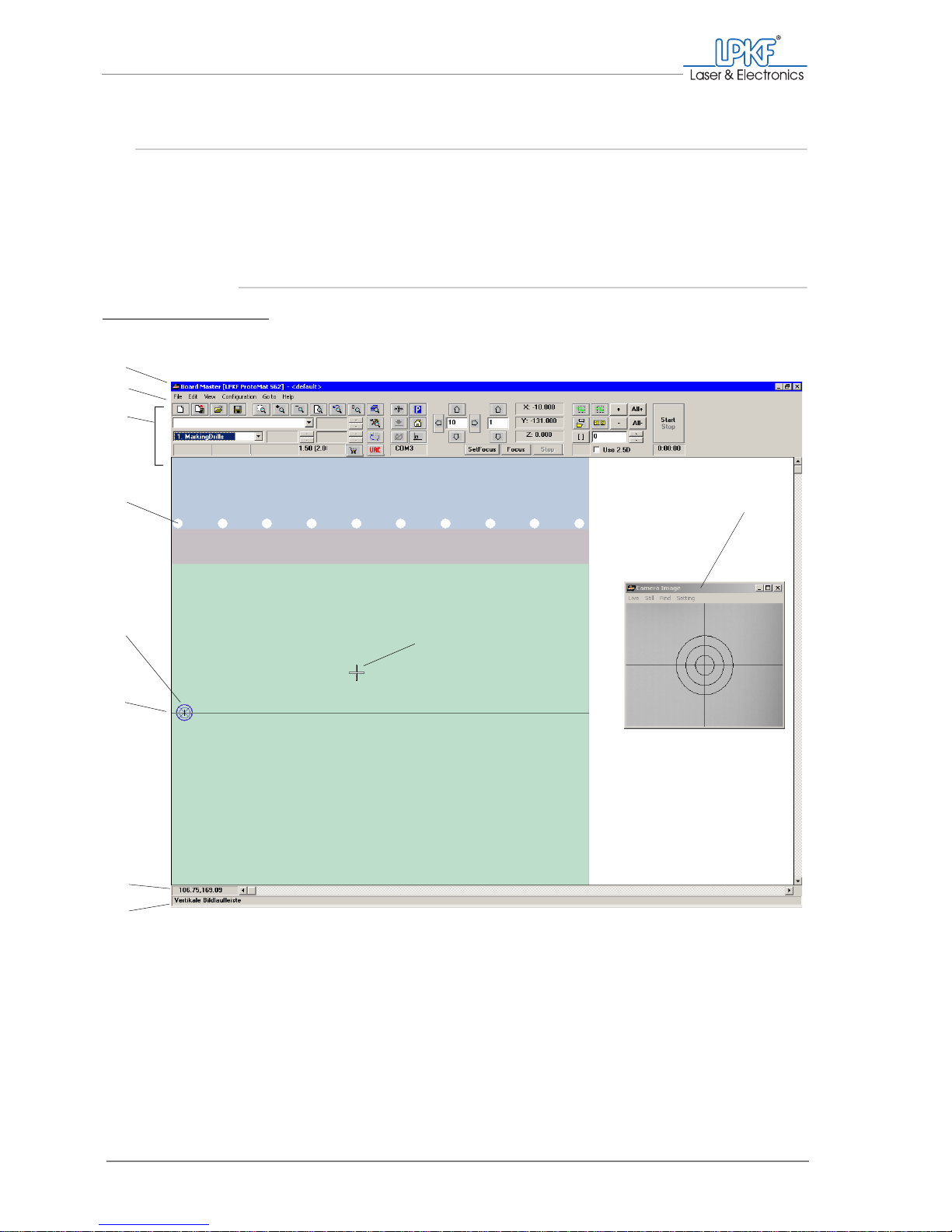
Fig. 20: BoardMaster user interface
1 Title bar
2 Main menu
3 Function bar
4 Tool holder/magazine
5 Current position of the
milling/drilling head
6 Mirror axis
7 Mouse pointer co-ordinates
8 Status bar
9 Mouse pointer
10 Camera image applica-
tion window (VisionSystem option only)
1
2
3
5
6
7
8
9
10
4
Page 57

Manual tasks and settings
Operating Manual 7.1 Rev.: 18.06.2008 55
Title b ar The title bar shows the program name, the circuit board plotter used as
well as the name of any loaded or newly created job.
Main menu The menu bar lists all available menus.
Function bar The function bar shows the functions used for manual control of the cir-
cuit board plotter and for starting automatic machining processes.
Tool holder/magazine The tool magazine indicates the individual tool holders. If the tools have
been defined in the tool holders, each tool type is indicated in colour.
Current position of the
milling/drilling head
The blue cross-hair shows the current position of the milling/drilling head.
Mirror axis Mirror axis of the work area. The base material should be positioned in
the centre of the mirror axis.
Mouse pointer co-ordi-
nates
The current X and Y co-ordinates of the mouse pointer referenced to the
HOME position.
Status bar The status bar provides information about the functions of buttons, dis-
plays or areas where the cursor is currently located.
Camera image application
window (optional)
The Camera image application window will only appear if the
VisionSystem has been installed. The window displays the area monitored by the camera. Please note that this area does not correspond to
the current position of the milling/drilling spindle.
Note: Detailed information about the functions of the individual operating
elements can be found in the BoardMaster manual.
Page 58
Finding out about BoardMaster
56 ProtoMat®S62
4.3.2 Frequently used functions
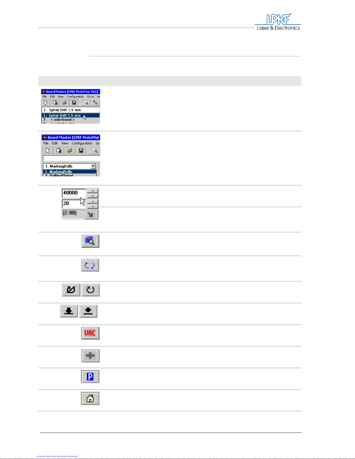
Frequently used functions can be called from the function bar.
Designation Function, note
Tool selection list Picking up/setting down the desired tool
Only the tools set up in the tool magazine dialogue box (Tool positions window) are dis-
played.
Phase selection list Select the production phase
The phases required for the selected production
type are displayed in the order of processing.
The current phase is preselected.
Rotation speed Set the motor speed for the selected tool
(the default setting depends on the tool).
Milling speed Set the feed rate for the selected tool when mill-
ing
(the default setting depends on the tool).
Phase configuration Open the Phases window .
Configure the phases (phase sequence, data
display colours, 2.5 D mode).
Toolbox dialog Open the Tool positions window.
Define the tool positions in the tool magazine.
Motor on
Motor off
Starts the milling/drilling spindle.
Stops the milling/drilling spindle.
Lift head
Lower head
Lifts the milling/drilling head.
Lowers the milling/drilling head.
Vacuum on/off Switches the dust extraction on/off.
Move by mouse Move the milling/drilling head with the mouse.
Move to pause Move the milling/drilling head to the pause posi-
tion.
Move to home Move the milling/drilling head to the home posi-
tion.
Page 59
Manual tasks and settings
Operating Manual 7.1 Rev.: 18.06.2008 57
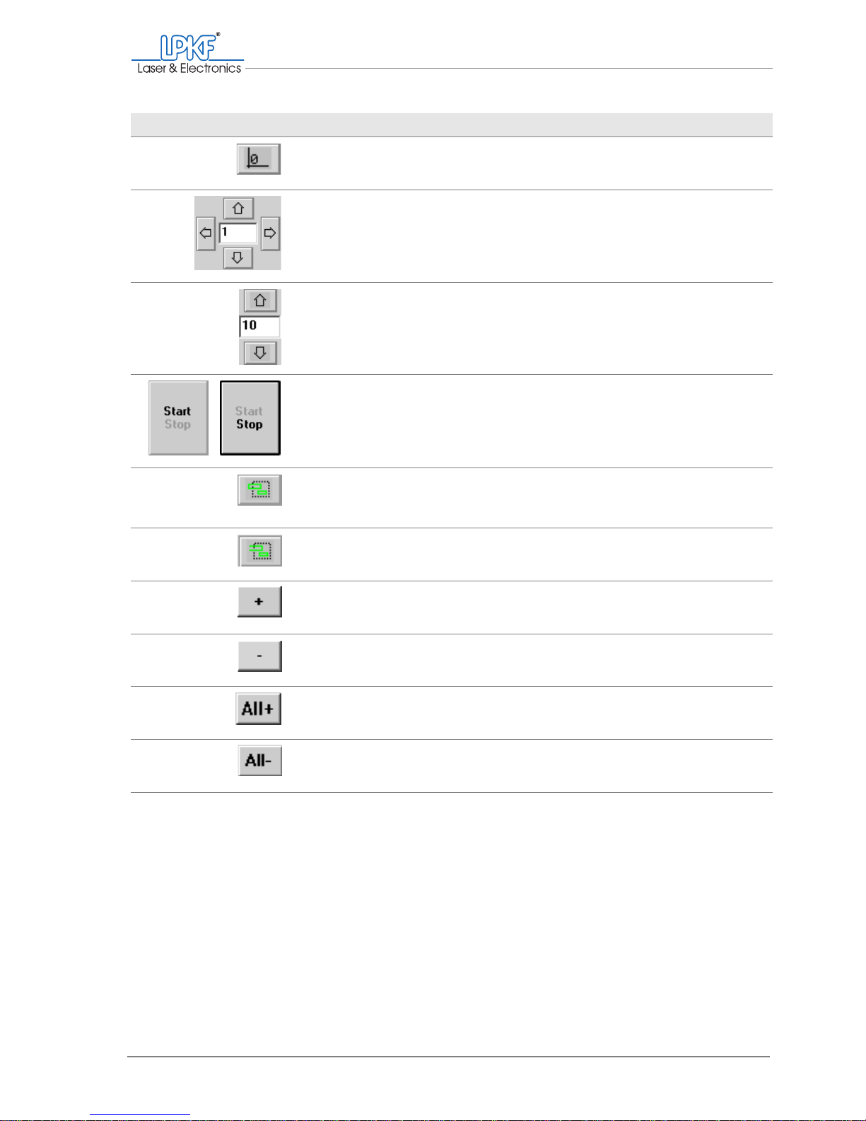
Move to zero Move the milling/drilling head to the zero posi-
tion.
Move to y+
Move to x-
Move to x+
Move to y-
Move the milling/drilling head horizontally.
Enter the increment in mm in the input box.
Move to z+
Move to z-
Move the milling/drilling head vertically.
Enter the increment in mm in the input box.
Start/Stop Start/stop the current production phase.
Add lines Add all (line) segments connected with the selec-
tion area.
Add segments Add all (line) segments within the selection area.
+ Activate selected elements for production.
- Deactivate selected elements
All+ Activate all elements for the current production
phase
All- Cancel the activation of all elements
Designation Function, note
Page 60
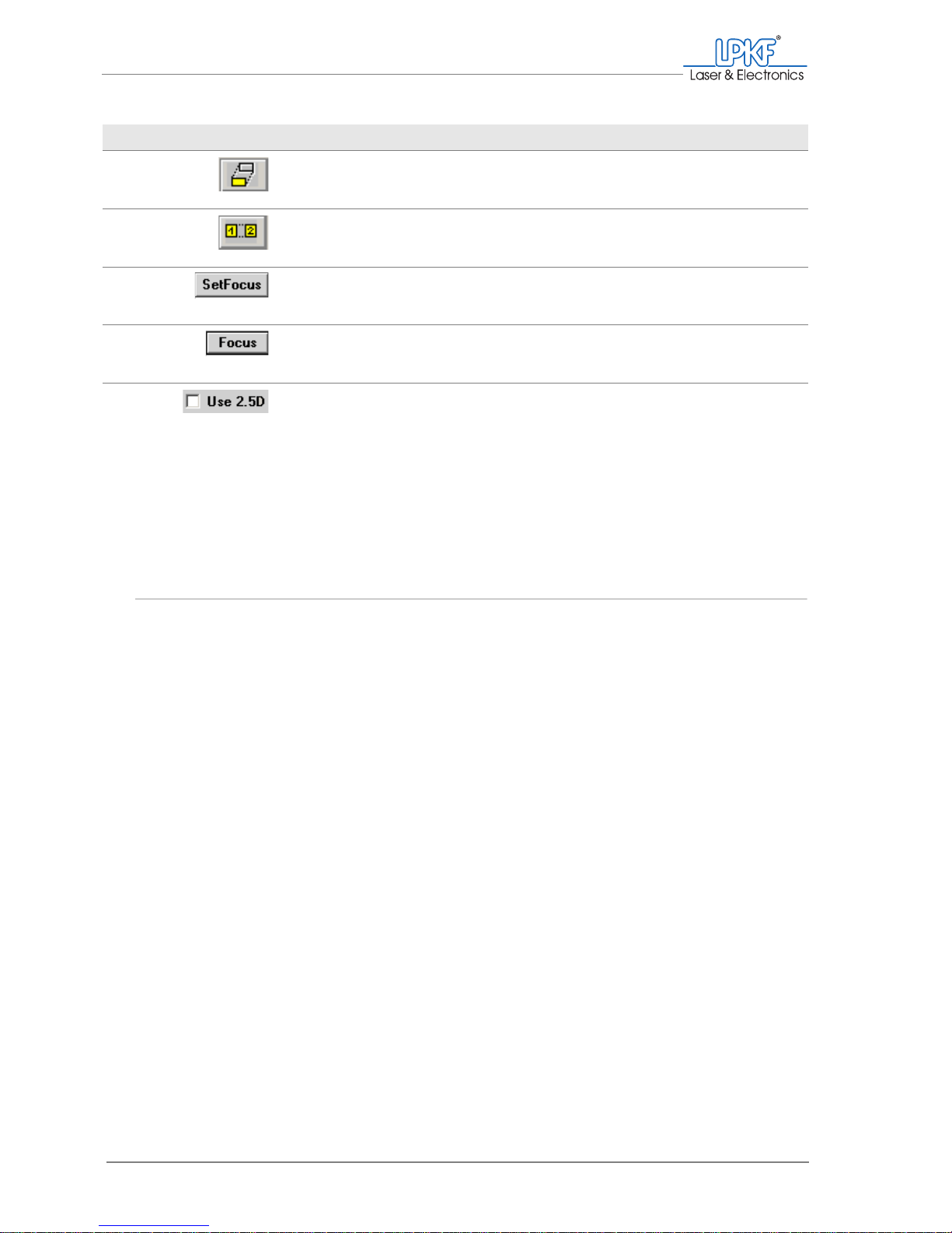
Positioning the milling/drilling head
58 ProtoMat®S62
When entering numerical values, decimal places must be separated by a
point (not a comma).
4.4 Positioning the milling/drilling head
The milling/drilling head can be positioned at will above the traversing
table. Thereby also the traversing t able will be moved. Th e co-ordination
of both traversing directions is controlled by BoardMaster. In the following, this procedure will be denoted as "moving the milling/drilling head".
Move project Move a project on the work area with the mouse.
Copy project Copy a project and position the copy on the work
area with the mouse.
SetFocus Save the vertical position of the milling/drilling
head as the focus position.
Focus Move the milling/drilling head vertically to the
saved focus position.
Use 2.5 D A check mark appears to indicate that
2.5 D mode has been activated (as a status display only; the mode must be activated in the
Phases window).
Designation Function, note
Page 61
Manual tasks and settings
Operating Manual 7.1 Rev.: 18.06.2008 59
Moving the milling/drilling head to a predefined position
To load the circuit board plotter, create a pass hole system or set up the
co-ordinate system, the milling/drilling head can be moved to defined
positions above the traversing table.
1. Click on one of the following buttons to move the milling/drilling
head to a predefined position.
The following positions are possible:
[ ] The milling/drilling head and the traversing table are moved automatically
to the selected position.
Move to pause
Pause position: The milling/drilling
head moves to the right, the traversing table moves forward.
Use:
Loading the circuit board plotter
Move to home
Home position: The milling/drilling
head moves to the mirror axis
above the left pass hole pin; the traversing table moves to the central
area.
Use:
Creating a pass hole system.
Move to zero
Zero position: The milling/drilling
head moves to the left, the traversing table moves backwards.
Use:
Reference point in BoardMaster,
definition of co-ordinate system
Page 62
Positioning the milling/drilling head
60 ProtoMat®S62
Moving the milling/drilling head step by step in the X/Y direction
1. Enter the desired increment in mm in the input box between the
arrow buttons (Move to x/y).
2. Click on the button for the desired direction.
The milling/drilling head or the traversing table is moved by the entered
value in the following direction.
Note: If the message "Outside the adjustment range" appears, the desired
value is too large.
Click on Yes to move the milling/drilling head to the edge of the traversing
range.
[]
Moving the milling/drilling head with the mouse
1. Click on the Move by mouse button.
2. In the work area, click on the desired position for the milling/drilling
head.
The milling/drilling head moves to the desired position.
or:
Press and hold down the left mouse button and drag the milling/drilling head across the traversing range.
The milling/drilling head will follow the movements of the mouse.
Note: You need to reactivate the Move by mouse button every time you
wish to move the milling/drilling head with the mouse.
[]
Move to x- The milling/drilling head moves to the left.
Move to x+ The milling/drilling head moves to the right.
Move to y+ The work table moves forwards.
Move to y- The work table moves backwards.
y+
y-
x+
x-
Page 63

Manual tasks and settings
Operating Manual 7.1 Rev.: 18.06.2008 61
Moving the milling/drilling head vertically
1. Enter the desired increment in mm in the input box between the
buttons Move to z+/z-.
2. Click on the button for the desired direction.
Note: If the message "Outside the adjustment range" appears, the desired
value is too large.
Click on Yes to lift or lower the milling/drilling head up to the maximum
value.
[ ] The milling/drilling head will be lifted/lowered by the desired value.
Page 64
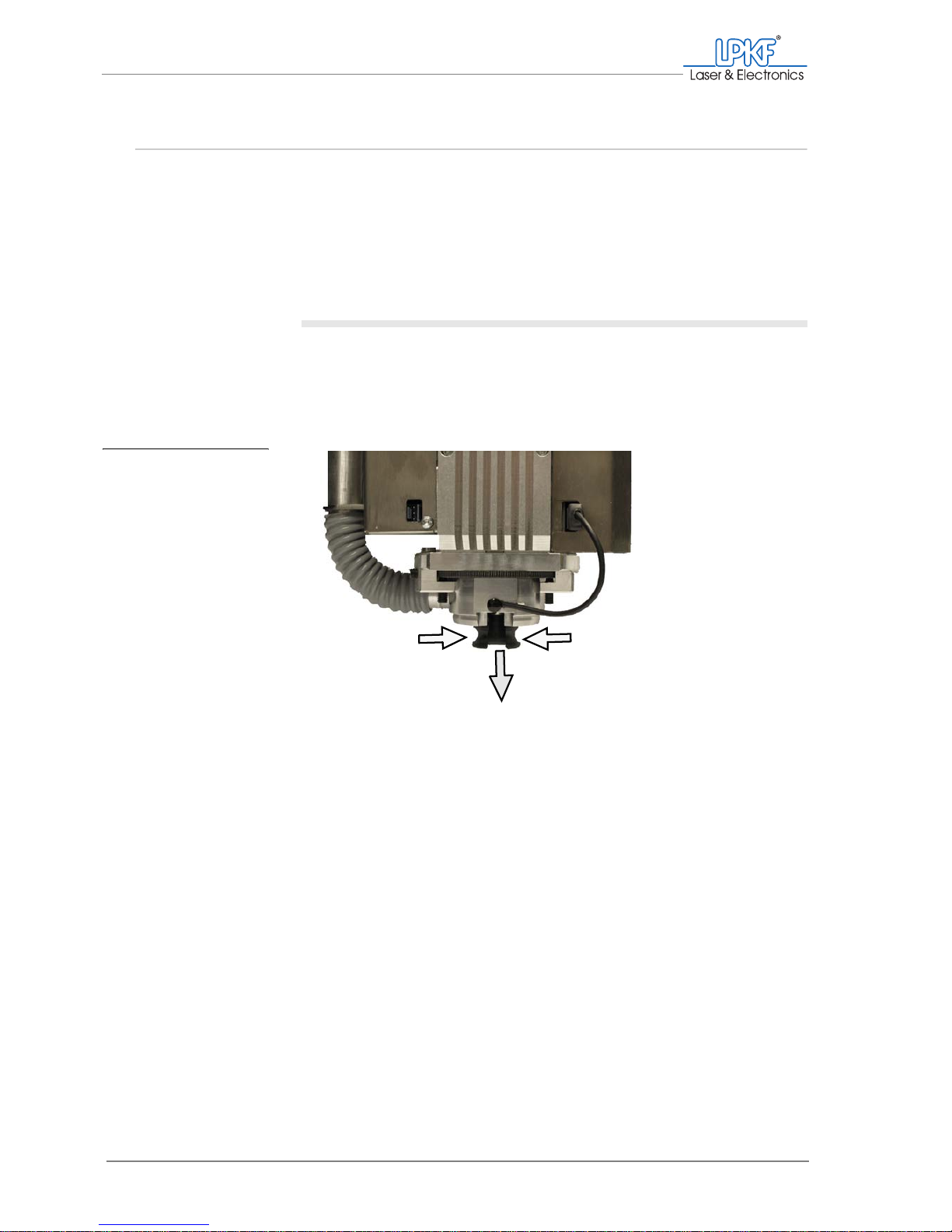
Mounting/Dismounting the milling depth limiter base
62 ProtoMat®S62
4.5 Mounting/Dismounting the milling depth limiter base
In order to ensure that milling will always be performed at the exact
working depth, you need to mount the milling depth limiter's plastic base
included in the scope of delivery or the brush head which is available to
purchase as an accessory. You should only dismount/replace the
base/brush head for special tasks such as drilling pass holes, cleaning
and maintenance.
Dismounting the plastic base/brush head
1. If it is not already there, move the milling/drilling head to the zero
position for easier access to the base/brush head.
2. Carefully squeeze the plastic base/brush head and pull it down and
out of the milling/drilling head.
[ ] The plastic base/brush head is dismounted.
Fig. 21: Removing the
plastic base
from the milling
depth limiter
1 Squeeze the plastic base/brush head 2 Pull the plastic base/brush head down and out
1
2
Page 65
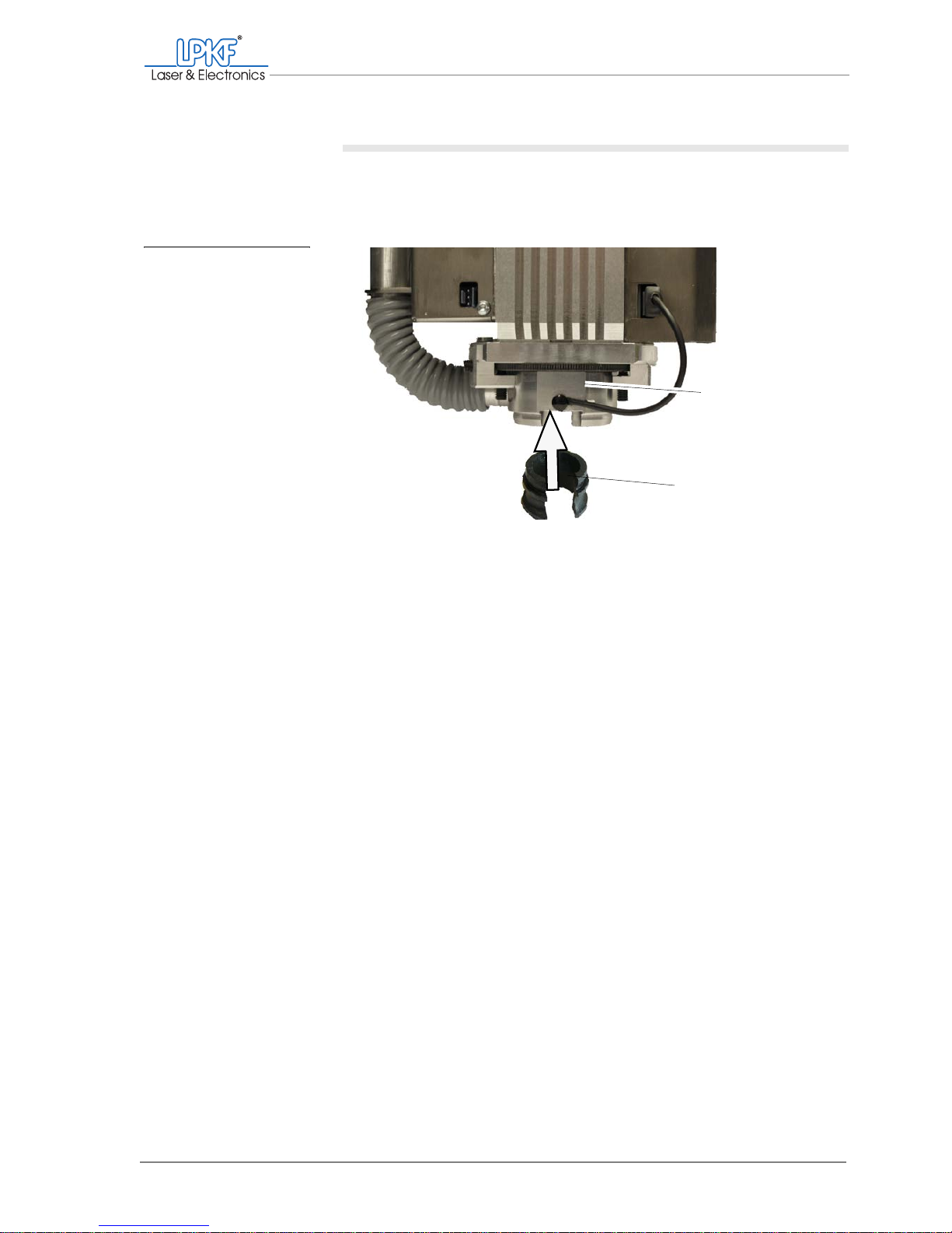
Manual tasks and settings
Operating Manual 7.1 Rev.: 18.06.2008 63
Mounting the plastic base/brush head
1. Take a firm hold of the milling/drilling head at the top to prevent it
lifting in the following and push the plastic base/brush head into the
milling depth limiter from below.
2. Rotate the base until the opening is oriented to the front.
[ ] The plastic base/brush head is smounted.
Fig. 22: Fitting the plastic
base on the milling
depth limiter
1 Milling depth limiter 2 Plastic base
1
2
Page 66
Loading
64 ProtoMat®S62
4.6 Loading
To avoid material damage, the circuit board plotter must only be loaded in
the pause position.
4.6.1 Loading and setting up the base material
The circuit board plotter has been designed for the use of base materials
with pass holes. We recommend the use of pre-drilled base materials at
all times. If your base material has no pass holes, you must drill them first
(see chapter ‚ "Drilling pass holes into the drilling underlay", on page 80).
Loading base material
1. Click on the Move to pause button in order to load the traversing
table.
2. Remove any material swarf from the traversing table with a soft
brush or a moistened cloth.
3. Set the drilling underlay down on the traversing table so that the
pass hole pins slot into the pass holes.
4. Set the base material down on the drilling underlay with the side to
be processed facing up so that the pass hole pins slot into the pass
holes.
5. Make sure that the pass hole pins do not protrude out of the base
material.
6. Using a non-residue adhesive tape, stick the edges of the base
material to the drilling underlay.
[ ] Now you can set up the work area.
WARNING
Health hazard!
The swarf and dust generated during material processing can
cause eye injuries and allergies.
› Extract the swarf and dust or remove them with a brush or mois-
tened cloth. N
EVER blow compressed air through the acoustic
cabinet.
Page 67
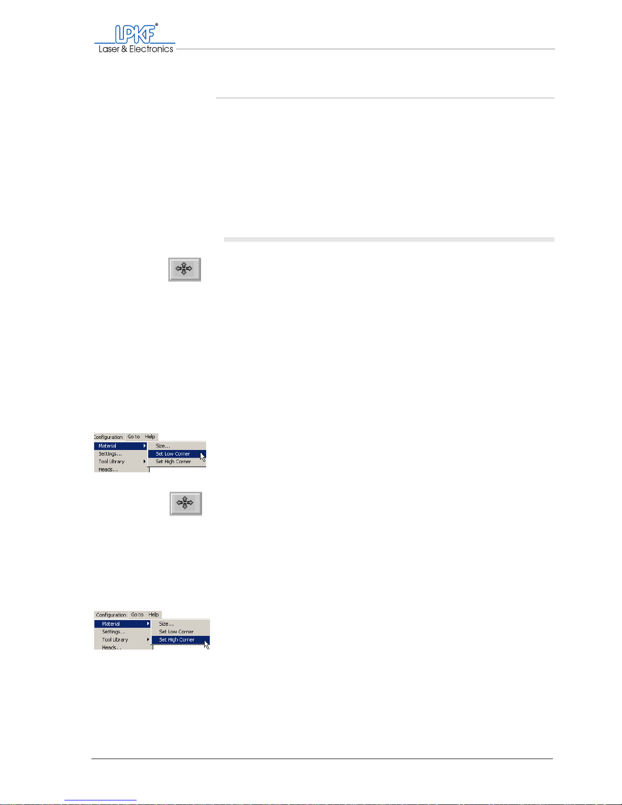
Manual tasks and settings
Operating Manual 7.1 Rev.: 18.06.2008 65
Setting up the work area
To get optimum use of the base material, you first need to define the work
area. Thereby the milling depth limiter's plastic base must be located
entirely above the base material. Accordingly, when setting up the work
area, you must make sure that the milling/drilling head is positioned over
the base material with at least 12 mm clearance to the edges of the
material to be processed.
Make absolutely sure to set the co-ordinates in the order specified
(starting with the front left-hand corner - then the rear right-hand corner).
Defining the work area
1. Click on the Move by mouse button.
2. Drag the mouse pointer with the left mouse button pressed to the
front left-hand corner of the desired work area.
The milling/drilling head will move immediately and can be positioned directly with the mouse.
Note: If you release the mouse button before completing the positioning
task, you will need to click on the Move by mouse button again before resuming.
3. Make sure that the milling/drilling head is in the correct position with
the milling depth limiter's plastic base located entirely above the
base material. The pass hole pins must not be located in the work
area.
4. In the BoardMaster menu bar, click on Configuration > Material >
Set Low Corner.
The co-ordinates for the front left-hand corner of the work area are re ad in.
5. Click on the Move by mouse button.
6. Drag the mouse pointer with the left mouse button pressed to the
rear right-hand corner of the desired work area.
The milling/drilling head will be positioned following the movement of the
mouse.
7. Make sure that the milling/drilling head is in the correct position with
the milling depth limiter's plastic base located entirely above the
base material.
8. In the BoardMaster menu bar, click on Configuration > Material >
Set High Corner.
The co-ordinates for the rear right-hand corner are read in and the base
material is displayed in dark grey in BoardMaster.
Page 68
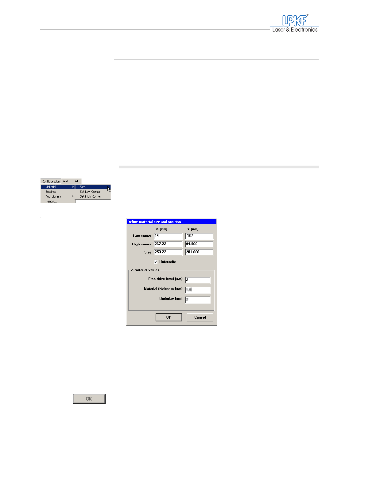
Loading
66 ProtoMat®S62
Defining the material height and z values
BoardMaster is factory-set with the following z values:
If you wish to use a thinner/thicker material or a different drilling underlay,
you will need to modify the values accordingly.
The moving-free height defines the distance between milling/drilling head
and material.
Defining the material height and z values
1. In the BoardMaster menu bar, click on Configuration > Material >
Size....
The Define material size and position window is opened.
The x and y values show the co-ordinates you have defined and the size
of the work area.
2. Enter the thickness of the material to be processed in mm in the
Material thickness [mm] input box.
3. Enter the thickness of the drilling underlay used in mm in the
Underlay [mm] input box.
4. Click on OK.
[ ] The work area is readily set up.
Material thickness: 1.60 mm
drilling underlay: 2 mm
Moving free height: 2 mm
Fig. 23: Defining the mate-
rial size and position
Page 69

Manual tasks and settings
Operating Manual 7.1 Rev.: 18.06.2008 67
4.6.2 Setting up tools
Before you load the tool magazine, you need to define a unique position
for each tool in it.
I.
Opening the tool magazine dialogue box
1. Click on the button for the Toolbox dialog.
2. Click on Yes to move the milling/drilling head to the pause position.
The Tool Positions input window opens.
The tool magazine can hold up to ten tools. The positions specified on
the left of the input window under Pos. correspond to the arrangement of
the tool holders from left (position 1) to right (position 10) in the tool magazine.
Fig. 24: Tool positions input window
1 Position in the tool magazine 2 Tool selection lists
12
_
Page 70
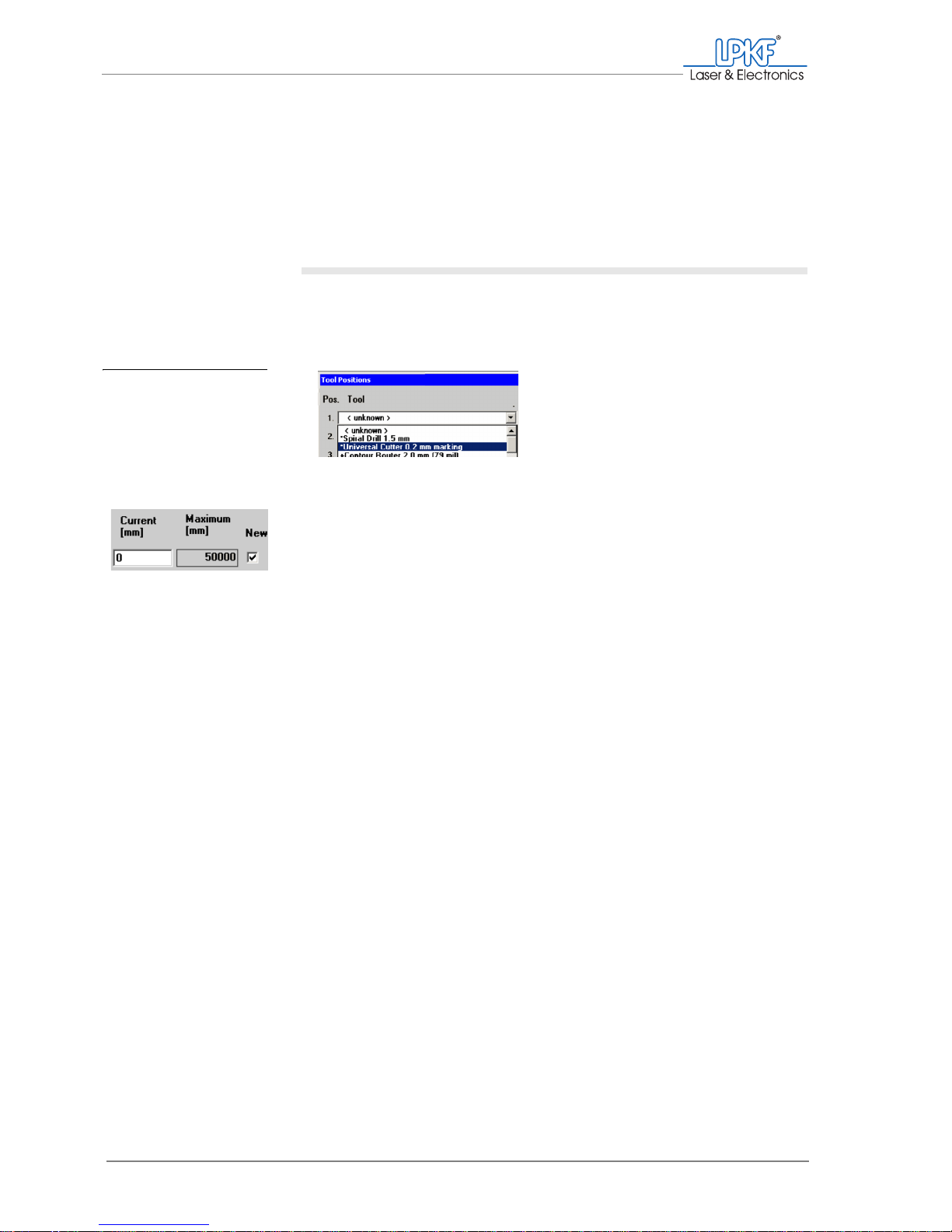
Loading
68 ProtoMat®S62
You can select one tool in each of the tool selection lists under Tool (2).
Each selection list contains all available tools.
Note: The most recently selected tools always appear as the default selections.
If you have already loaded a job, the required tools will be marked * or + in the
selection lists.
II. Assigning tool positions
1. In the selction list Tool for Pos. 1 select one of the required tools
(e.g. the Universal Cutter 0.2 mm marking) for centre-punching
the drill holes).
2. If you want to use a new or unused tool:
Activate the checkbox in the New column.
3. Select the other tools you need from the following selection lists.
Once you have assigned a tool position for each of the required tools, the
input window could look like this:
Fig. 25: Assigning tool po-
sitions
Page 71
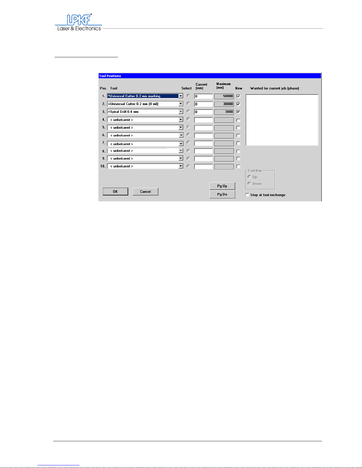
Manual tasks and settings
Operating Manual 7.1 Rev.: 18.06.2008 69
Note: The order of the tool positions can be selected at will. During operation, the tools are taken out of the correct tool holder automatically.
[ ] Once set up, the tools are displayed in the tool selection list on the func-
tion bar.
Fig. 26: Defined tool positions
Page 72
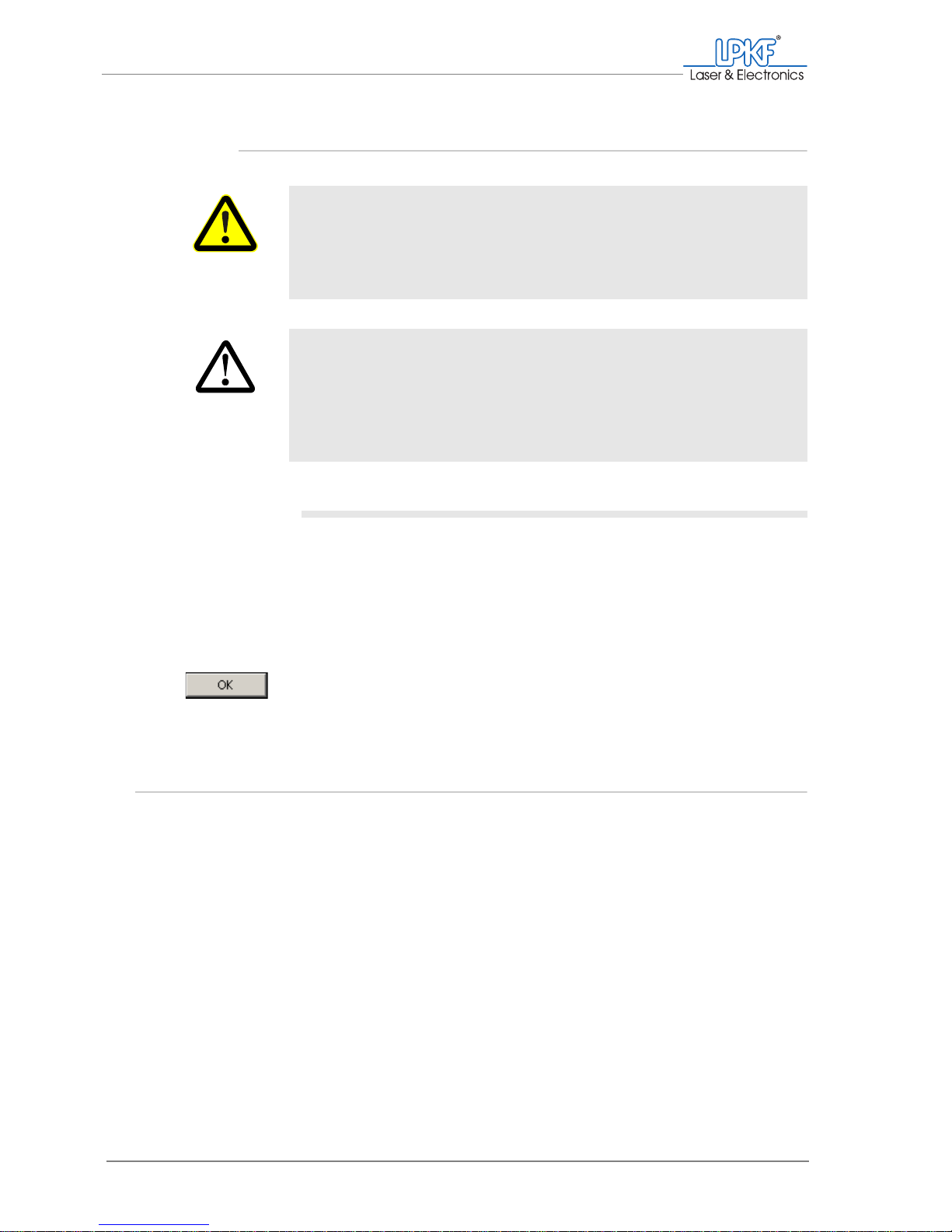
Selecting a tool for processing
70 ProtoMat®S62
4.6.3 Inserting tools
Inserting tools
1. With the tip pointing downwards, push the desired tools as far as
they will go into the tool holders defined in the Tool positions window (Pos.).
Note: Position 1 is on the left-hand side of the tool magazine, position 10
is on the right.
2. Close the acoustic cabinet cover.
3. Click on OK.
4.7 Selecting a tool for processing
To create a bore or milling track, you need to have set up the desired tool
and inserted it into the correct position in the tool magazine. The tools
currently set up are displayed in the tool selection list. The number in
front of the tool name corresponds to the position in the tool magazine.
WARNING
Risk of injury!
The tools to be used are very sharp edged and can cause cuts
and stab injuries.
› Handle tools carefully and keep them in the toolbox when not in
use.
CAUTION
Material damage due to incorrect loading!
If you insert the tools into other positions than those defined by
BoardMaster, the milling/drilling head and spindle and the tools
can become damaged.
› Insert the tools only into the tool holder (positions) defined in
BoardMaster.
Page 73
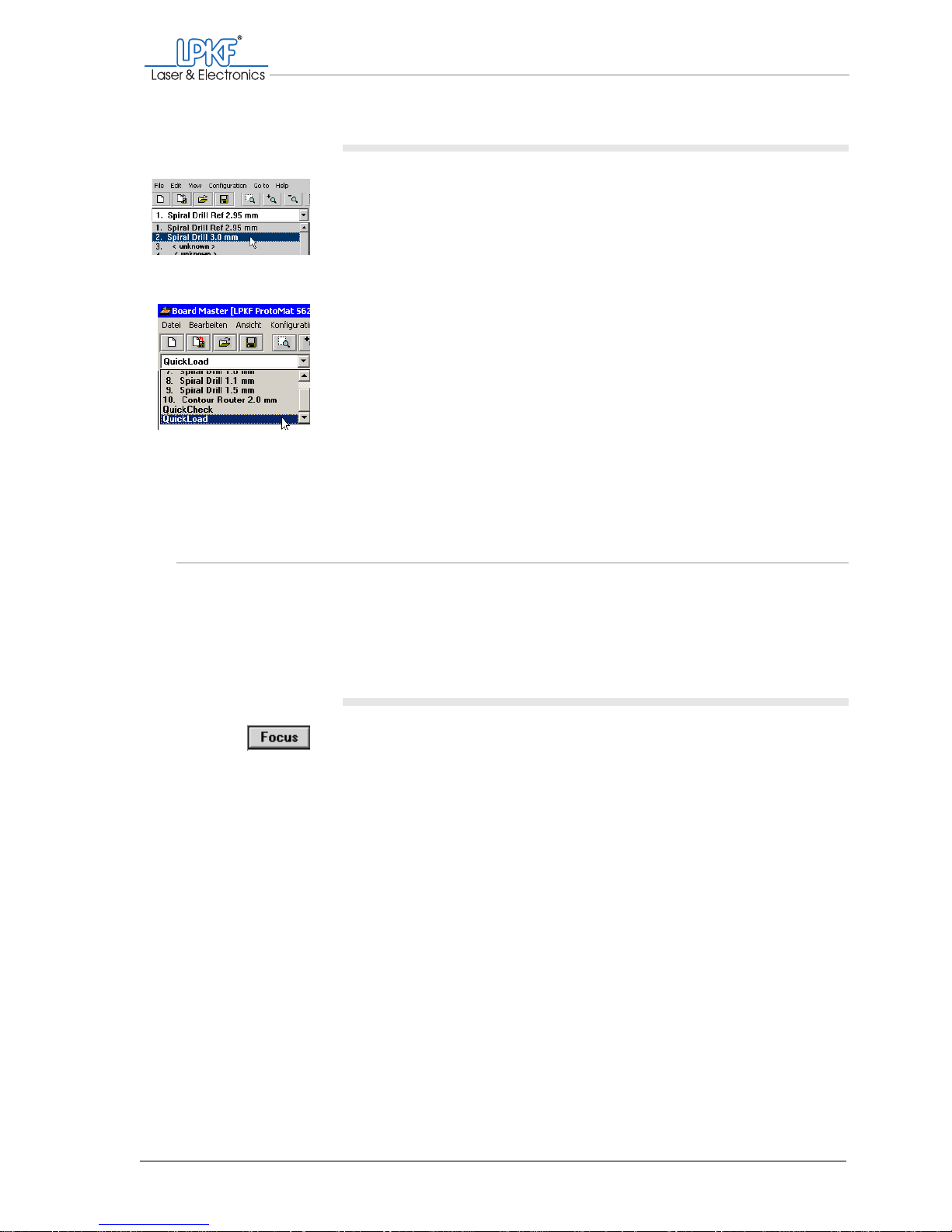
Manual tasks and settings
Operating Manual 7.1 Rev.: 18.06.2008 71
Picking up/Setting down a tool
1. Select the desired tool in the tool selection list.
If there is still a tool in the milling/drilling head, it will be set down first. The
desired tool is then taken up and the milling/drilling head pauses above
the tool holder.
2. To set down a tool loaded in the milling/drilling head without taking
up a new one:
– Select the QuickLoad entry in the tool selection list.
The tool is set down in the defined tool holder.
[]
4.8 Setting the focus (VisionSystem only)
The focus is determined by the height position of the milling/drilling head.
This z value can be saved as a focus position. If the milling/drilling head
has moved vertically in the interim period, you can quickly reset the focus
position and accordingly the focus to the original value.
Setting the focus to the saved value
1. On the function bar, click on Focus.
2. If the camera image is not focussed, reset the focus position (see
"Adjusting the focus position").
[]
Page 74
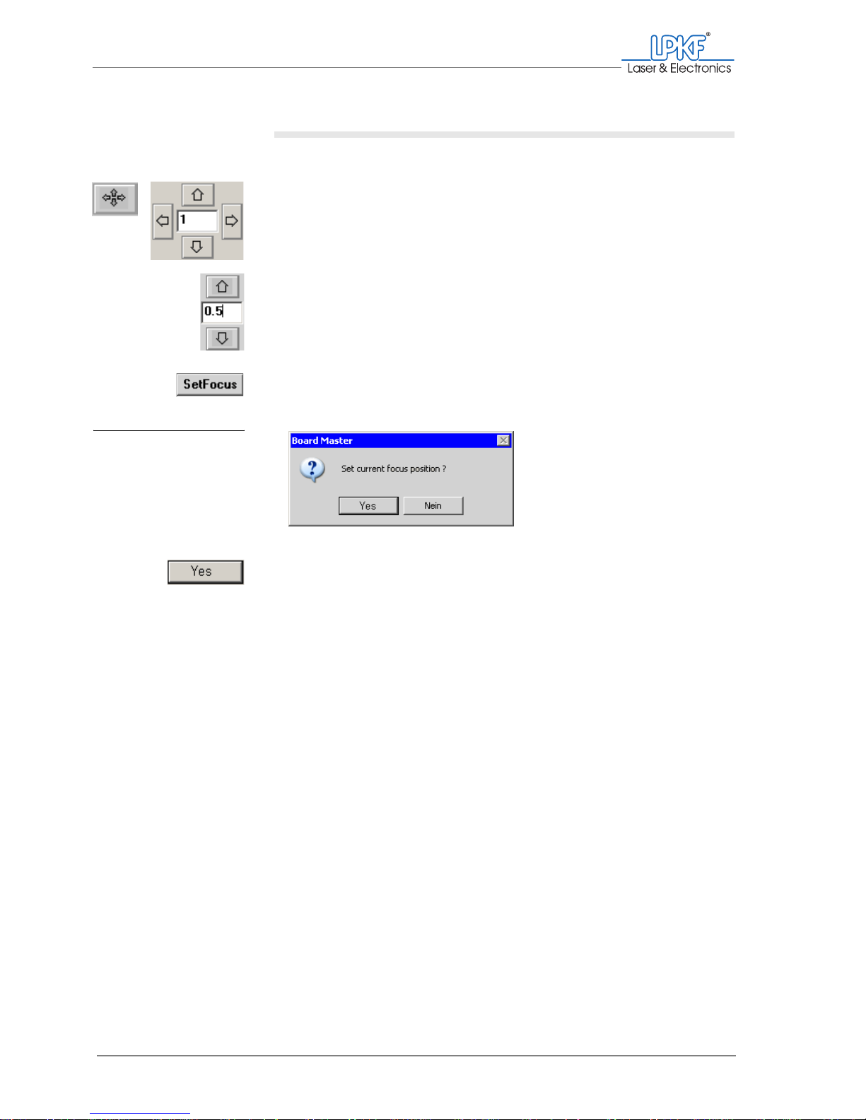
Setting the focus (VisionSystem only)
72 ProtoMat®S62
Adjusting the focus position
To set the focus position, the material to be used must be loaded.
1. Move the milling/drilling head so that the camera is positioned
above an as high-contrast area as possible, e.g. a bore, or at the
edge of a milling.
You might need to place a thin printed sheet of paper on the material to be processed to serve as a contrast background.
2. Use the arrow buttons (Move to z+/z-) to move the milling/drilling
head vertically and focus the camera image.
For fine-tuning, enter a value of 0.05 or less in the input box
between the arrow buttons.
The camera image is focussed.
3. On the function bar, click on SetFocus.
The "Set current focus position ?" window appears.
4. Click on Yes.
[ ] The vertical position of the milling/drilling head is saved as the focus posi-
tion.
Fig. 27: Adjusting the focus
position
Page 75
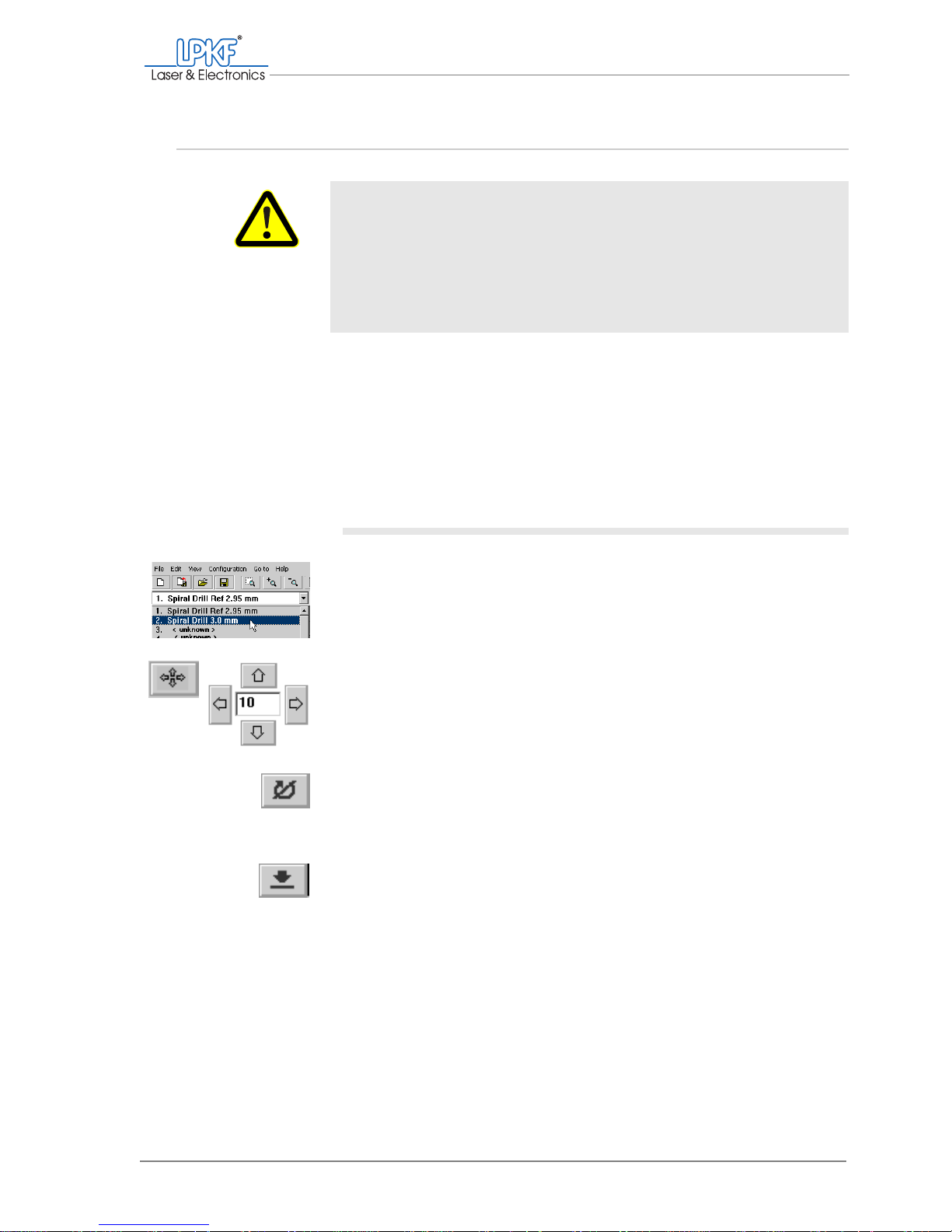
Manual tasks and settings
Operating Manual 7.1 Rev.: 18.06.2008 73
4.9 Drilling
For manual processing, the desired tool must be set up in BoardMaster
(Tool Positions window) and loaded in the corresponding tool holder
(see chapter 4.6.2‚ "Setting up tools", on page 67).
The available tools can be used to drill round holes up to 3 mm in diameter. You will need to use the Contour Router milling tool (suitable for use
for diameters 2.4 mm or larger) if you wish to drill larger holes/slots (see
"Milling" on page 61).
Drilling a hole
1. Select the desired drill in the tool selection list.
2. Move the milling/drilling head above the desired drilling position
with the mouse or the Move to x/y buttons.
3. Click on the Motor on button.
The milling/drilling spindle and the dust extraction (automatic mode only)
werden gestartet.
4. Click on the Lower head button.
Once the hole has been drilled, the milling/drilling head will be lifted automatically.
WARNING
Health hazard!
The processing of the materials can give rise to dusts and gases
hazardous to your health.
› You must switch on the dust extraction before processing mate-
rials of any type. Extract the dust and material residues or
remove them with a brush or moistened cloth;
DO NOT blow
them out.
Page 76
Milling
74 ProtoMat®S62
5. Move the milling/drilling head as necessary to drill more holes with
the same drill.
or:
Click on the Motor off button.
[ ] The milling/drilling spindle and the dust extraction (automatic mode only)
are switched off.
4.10 Milling
Please note that milling results are dependent upon tool penetration
depth. Insufficient material removal between the later conductor tracks
can cause the circuit board to malfunction. In the case of the Universal
Cutter and Micro Cutter conical mills, milling width is determined by penetration depth.
Always carry out a test milling on the base material to be used and check
the milling depth with a microscope to confirm sufficient material removal.
In order to ensure the desired milling width when using the Universal Cu t-
ter or Micro Cutter mills, you should check this with a measuring microscope.
Correct the milling depth if necessary before continuing work (see
chapter ‚ "Adjusting the milling depth/width", on page 76).
WARNING
Health hazard!
The processing of the materials can give rise to dusts and gases
hazardous to your health.
› Y ou must switch on the dust extra ction before processing ma te-
rials. Extract the dust and material residues or remove them
with a brush or moistened cloth; do
NOT blow compressed air
through.
Page 77
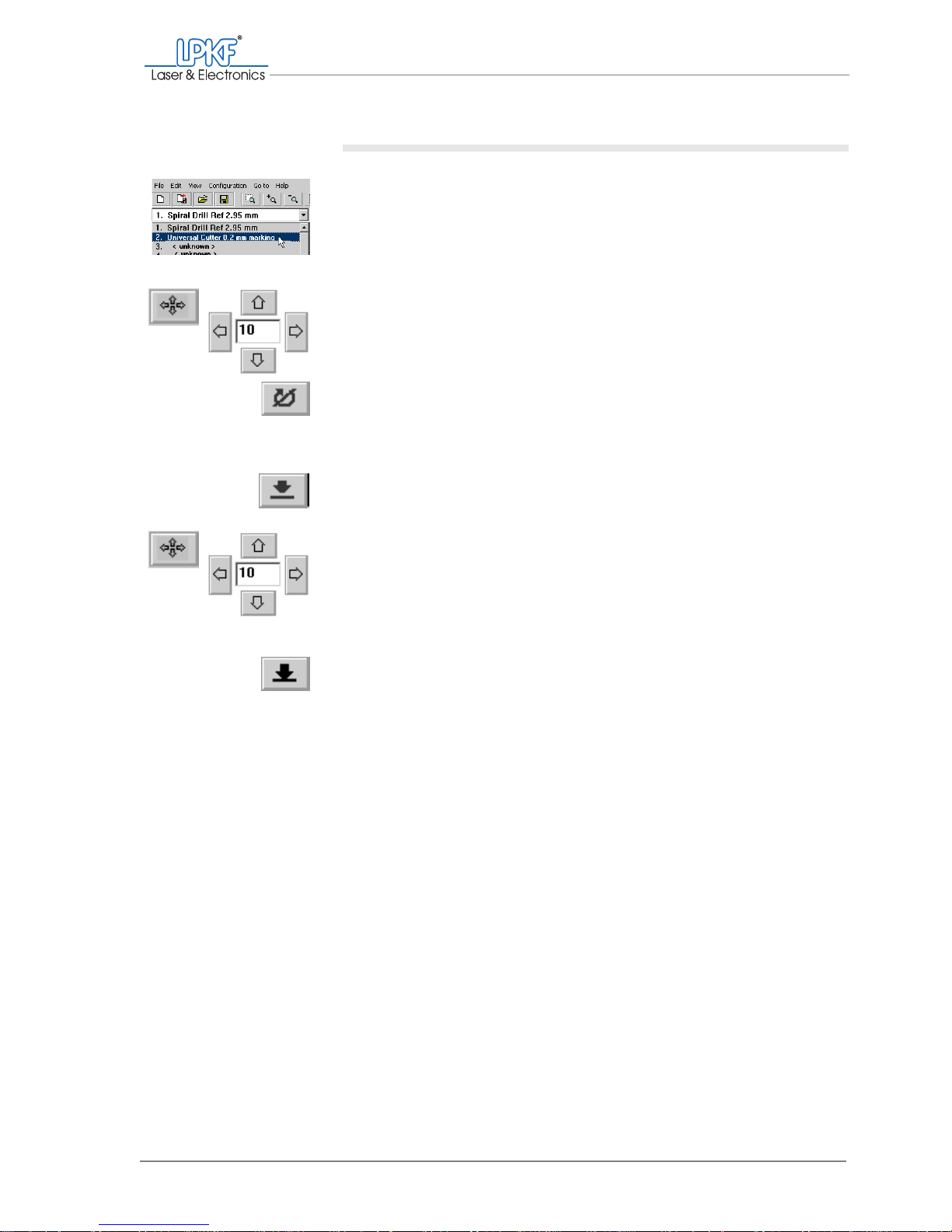
Manual tasks and settings
Operating Manual 7.1 Rev.: 18.06.2008 75
Creating a milling track
1. Select the desired mill in the tool selection list.
The mill is taken out of the tool magazine and the milling/drilling head
pauses above the tool holder.
2. Move the milling/drilling head with the mouse or the Move to x/y
buttons to the starting point of the desired milling track .
3. Click on the Motor on button.
The milling/drilling spindle and the dust extraction (automatic mode only)
will be started.
4. Click on the Lower head button.
The milling/drilling head is lowered onto the base material.
5. Move the milling/drilling head with the mouse or the Move to x/y
buttons in the desired direction and distance.
The milling track is created.
6. Click on the Lift head button.
The milling/drilling head is lifted slightly.
7. If necessary create further milling tracks as with the same tool.
or:
Click on the Motor off button.
[ ] The milling/drilling head is lifted slightly; the spindle and dust extraction
(automatic mode only) are switched off.
Page 78

Milling
76 ProtoMat®S62
Adjusting the milling depth/width
By means ofthe milling/drilling depth limiter the surface removal can be
set exactly to the desired rate.
For conical formed mills (Universal Cutter , Micro Cutter), the milling width
has to be set using the milling depth limiter.
Adjusting the milling depth (cylindrical tools)
1. Turn the adjusting wheel on the milling/drilling head to the left to
increase the milling depth.
2. Turn the adjusting wheel on the milling/drilling head to the right to
reduce the milling depth.
Note: The milling depth can be set in increments of 2 µm.
3. Perform a milling test run.
4. Check the result with a magnifying glass.
5. Repeat the process until sufficient material is removed.
[ ] The milling depth has been set correctly.
Adjusting the milling width (Universal Cutter and Micro Cutter
only)
1. Turn the adjusting wheel on the milling/drilling head to the left to
mill a wider track.
2. Turn the adjusting wheel on the milling/drilling head to the right to
mill a narrower track.
Note: On the Universal Cutter, the milling width can be set in 4 µm increments; on the Micro Cutter it can be set in 2.3 µm increments.
3. Perform a milling test run and check the width with a measuring
microscope.
4. Repeat the process until the milling track has the desired width.
[ ] The milling width corresponds to the desired setting.
+
_
+
Page 79
Manual tasks and settings
Operating Manual 7.1 Rev.: 18.06.2008 77
4.11 Creating a pass hole system (basic equipment)
The ProtoMat®S62 traversing table is factory-set with a pass hole system for standard material sizes (9" x 12"). If, after a period of time, the
pass hole pins are not seated free of play anymore, you will need to create a new pass hole system. You will also need to do this if you wish to
process materials of smaller dimensions.
Required tool and acces-
sories
To create the pass hole system in the traversing table, you will need the
following tool and accessories:
• Spiral Drill Ref. 2.95 mm
for pass holes in the plastic strips on the traversing table.
• Spiral Drill .3.0 mm:
for pass holes in the drilling underlay and in the base material
• Pass hole pins 3 mm x 8 mm
• Press-in tool for pass hole pins
• Combined collet for removing existing pass hole pins
You must remember that the procedures for drilling pass holes in the traversing table (see "Preparation" on p age 65) differ from those for the vacuum table (see "Creating a pass hole system (vacuum table)" on
page 69).
Conditions The following information assumes that the Spiral Drill Ref 2.95 mm and
Spiral Drill .3.0 mm tools have been set up in BoardMaster and loaded in
the tool magazine accordingly. (see chapter 4.6.2‚ "Setting up tools", on
page 67)
To drill pass holes into the plastic strips on the traversing table, proceed
as follows:
I.
Preparing the circuit board plotter
1. Dismount the plastic base/brush head from the milling depth limiter
(see "Dismounting the plastic base/brush head" on page 62).
2. Click on the Move to pause button in order to move the traversing
table to the loading position.
Page 80
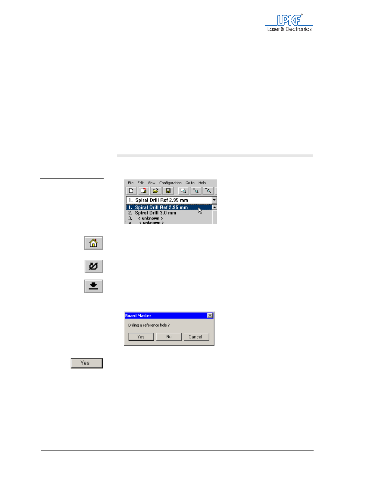
Creating a pass hole system (basic equipment)
78 ProtoMat®S62
3. Preparing the traversing table:
– Remove the drilling underlay from the traversing table.
– Pull the pass hole pins out of the red plastic strips using a collet.
– Move the plastic strips in the guide groove so that the new pass
holes can be positioned as appropriate for the size of your material.
If no more pass holes will fit in the plastic strips:
Lift the strips out of the guide groove and insert a new pair.
Note: The pass holes should be positioned at le ast 5 mm from the edge of
the base material.
Now you can drill the pass holes.
II. Drilling pass holes into pass hole strips
1. In the tool selection list select the Spiral Drill Ref 2.95 mm entry.
2. Click on the Move to home button.
3. Click on the Motor on button.
4. Click on the Lower head button.
A prompt asking if you wish to drill a pass hole will appear.
5. Click on Yes.
Fig. 28: Selecting pass
hole drills for pass
hole strips
Fig. 29: BoardMaster mes-
sage "Drill pass
hole?"
Page 81
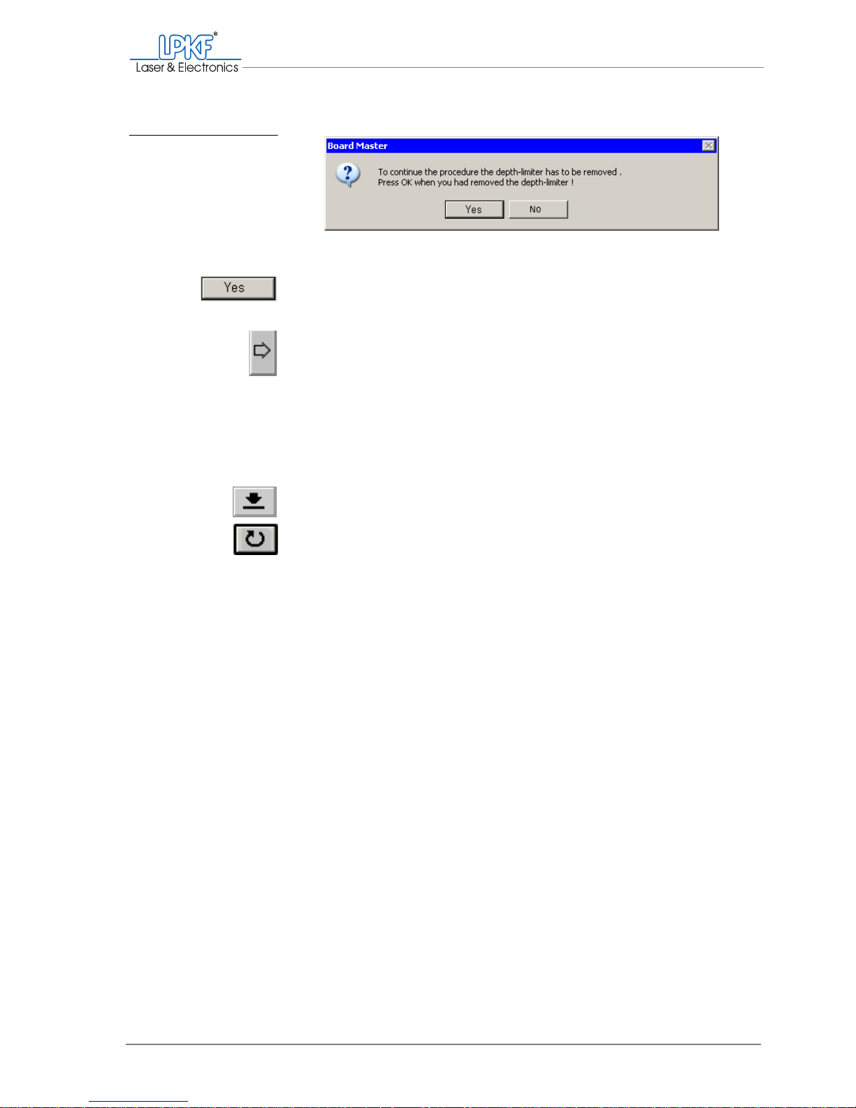
Manual tasks and settings
Operating Manual 7.1 Rev.: 18.06.2008 79
6. Check that the plastic base has been removed from the milling
depth limiter and click on Yes.
The pass hole will be drilled.
7. Using the arrow keys, move the milling/drilling head in the X direction so that it is located in the desired position above the right-hand
pass hole strip.
Take care not to move the milling/drilling head in the Y direction,
otherweise the pass hole will not be positioned exactly on the mirror
axis.
8. Make a note of the x value.
Note: LPKF base materials have a pass hole clearance of 295 mm.
9. Click on the Lower head button to drill the pass hole.
10. Click on the Motor off button.
11. If nesssescary drill new pass holes into the drill underlay
(see "Drilling pass holes into the drilling underlay").
[ ] Now you can insert the pass hole pins into the pass hole strips and
remount the plastic base on the milling depth limiter.
Fig. 30: BoardMaster mes-
sage "Depth limit-
er removed"
Page 82
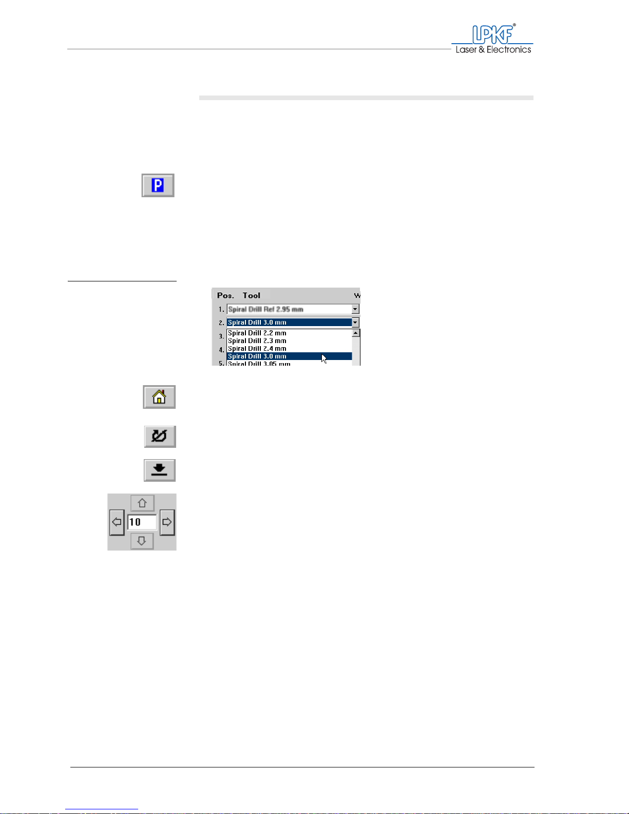
Creating a pass hole system (basic equipment)
80 ProtoMat®S62
Drilling pass holes into the drilling underlay
To drill pass holes into the drilling underlay, the Spiral Drill 3.0 mm must
be set up and positioned accordingly in the tool magazine.
1. Mount the plastic base on the milling depth limiter (see "Mounting
the plastic base/brush head" on page 63).
2. Click on the Move to pause button.
3. Pull any existing pass hole pins out of the plastic strips in the traversing table using flat nose pliers.
4. Place the base material/drilling underlay in the Y direction as centrally as possible on the traversing tables mirror axis.
5. On the function bar, click on the tool selection list and select the
entry 2. Spiral Drill 3.0 mm.
6. Click on the Move to home button.
7. Click on the Motor on button.
8. Click on the Lower head button.
The pass hole is drilled.
9. Use the Move to x+ button to move the milling/drilling head to the
desired position.
Take care not to move the milling/drilling head in the Y direction.
10. Make a note of the x value.
Fig. 31: Selecting pass
hole drills for base
material/drilling underlay
Page 83

Manual tasks and settings
Operating Manual 7.1 Rev.: 18.06.2008 81
11. Click on the Lower head button to drill the pass hole.
12. Click on the Motor off button.
[ ] To complete the pass hole system, yo u simply need to insert the p ass hole
pins (see chapter 4.13‚ "Inserting pass hole pins", on page 88) and mount
the plastic base on the milling depth limiter(see "Mounting the plastic
base/brush head").
4.12 Creating a pass hole system for the vacuum table
The scope of delivery of the vacuum table does not include a pass hole
system. To create the pass hole system, you will need the following tool
and accessories:
Required tool
and accessories
• Spiral Drill Ref. 2.95 mm
To drill the pass holes into the plastic strips and the vacuum table's
sinter plate
• Spiral Drill .3.0 mm:
To drill the pass holes into the base material (optional)
• Pass hole pins 3 mm x 10 mm
• Press-in tool for pass hole pins
The following information assumes that the Spiral Drill Ref 2.95 mm and
Spiral Drill .3.0 mmtools have been set up in BoardMaster and loaded in
the tool magazine accordingly (see chapter 4.6.2‚ "Setting up tools", on
page 67).
Page 84
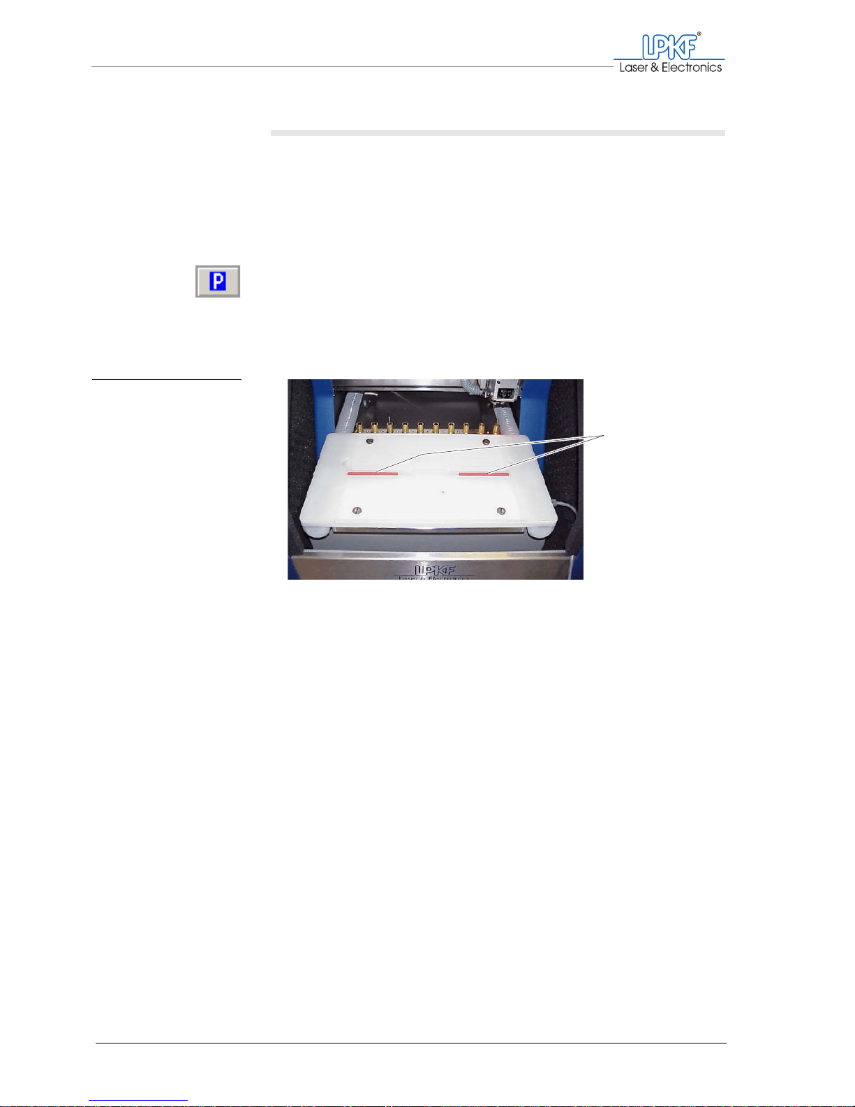
Creating a pass hole system for the vacuum table
82 ProtoMat®S62
Preparing the circuit board plotter and vacuum table
Before you can drill the pass holes, you need to prepare the circuit
board plotter:
1. Carefully squeeze the milling depth limiter's plastic base and pull it
down and out of the milling/drilling head.
If it is not already there, move the milling/drilling head to the zero
position for easier access to the base.
2. Click on the Move to pause button in order to move the traversing
table to the loading position.
3. Remove the sinter plate from the vacuum table.
4. Check that the red pass hole strips are in place in the vacuum
table.
5. If you are replacing an existing pass hole system:
– Use a collet to pull the pass hole pins out of the red plastic strips.
– Move the plastic strips in the guide groove so that the new pass
holes can be positioned as appropriate for the size of your material.
– If no more pass holes will fit in the plastic strips:
Lift the strips out of the guide groove and insert a new pair.
Note: The pass holes should be positioned at le ast 5 mm from the edge of
the base material.
[]
Fig. 32: Pass hole strips in
the vacuum table
1 Pass hole strips in the vacuum table
1
Page 85
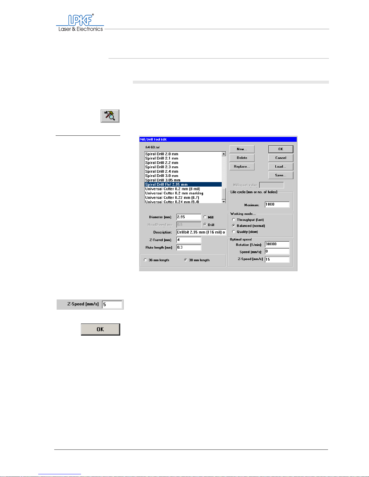
Manual tasks and settings
Operating Manual 7.1 Rev.: 18.06.2008 83
4.12.1 Drilling pass holes into pass hole strips
I. Setting parameters for drilling pass holes
1. Select the Spiral Drill Ref. 2.95 mm drill from the Tool selection
list.
2. Click on the Tool Lbrary button.
The Mill/Drill Tool Edit window is opens.
3. Make sure that in the fr4-60.tol selection list the Spiral Drill
2.95 mm pass hole drill is selected.
4. In the Optimal speed field, set the value for Z-Speed [mm/s] to 5.
5. Click on OK.
[ ] Next you need to set the machine parameters.
Fig. 33: Setting parameters
for drilling pass
holes
Page 86
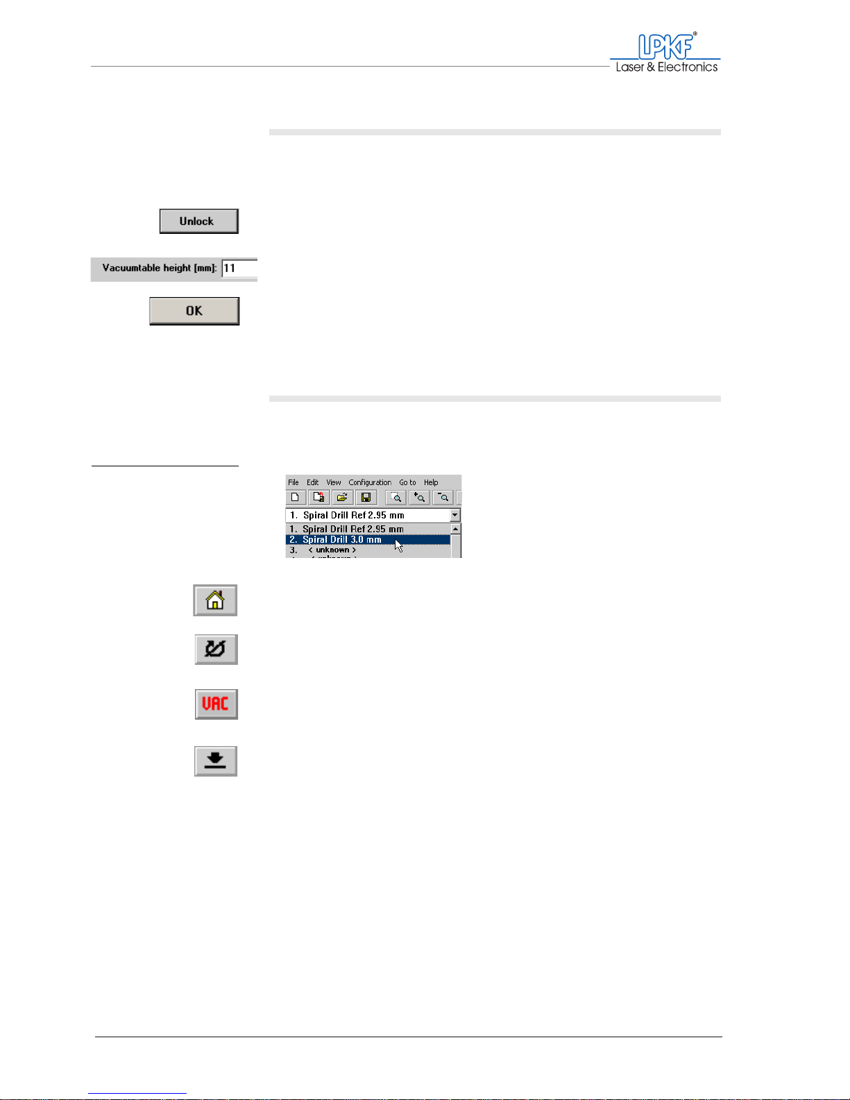
Creating a pass hole system for the vacuum table
84 ProtoMat®S62
II. Setting the machine parameters for drilling pass hole strips
1. In the main menu, click on Configuration > Settings.... .
The Machine settings window opens.
2. Click on Unlock.
3. Enter the value 11 in the Vacuum table height [mm] input box.
4. Click on OK.
[ ] Now you can drill the pass holes.
III. Drilling pass holes into pass hole strips
1. On the function bar, click on the tool selection list and select the
entry 2. Spiral Drill Ref 2.95 mm.
2. On the menu bar, click on the Move to home button.
The milling/drilling head moves to the HOME position.
3. On the function bar, click on the Motor on button.
The milling/drilling spindle and the dust extraction start up.
4. If the dust extraction does not start, click on the Vacuum on/off
button on the function bar.
5. On the function bar, click on the Lower head button.
The prompt „Drilling a reference hole ?“ appears.
Fig. 34: Selecting pass
hole drills for pass
hole strips
Page 87
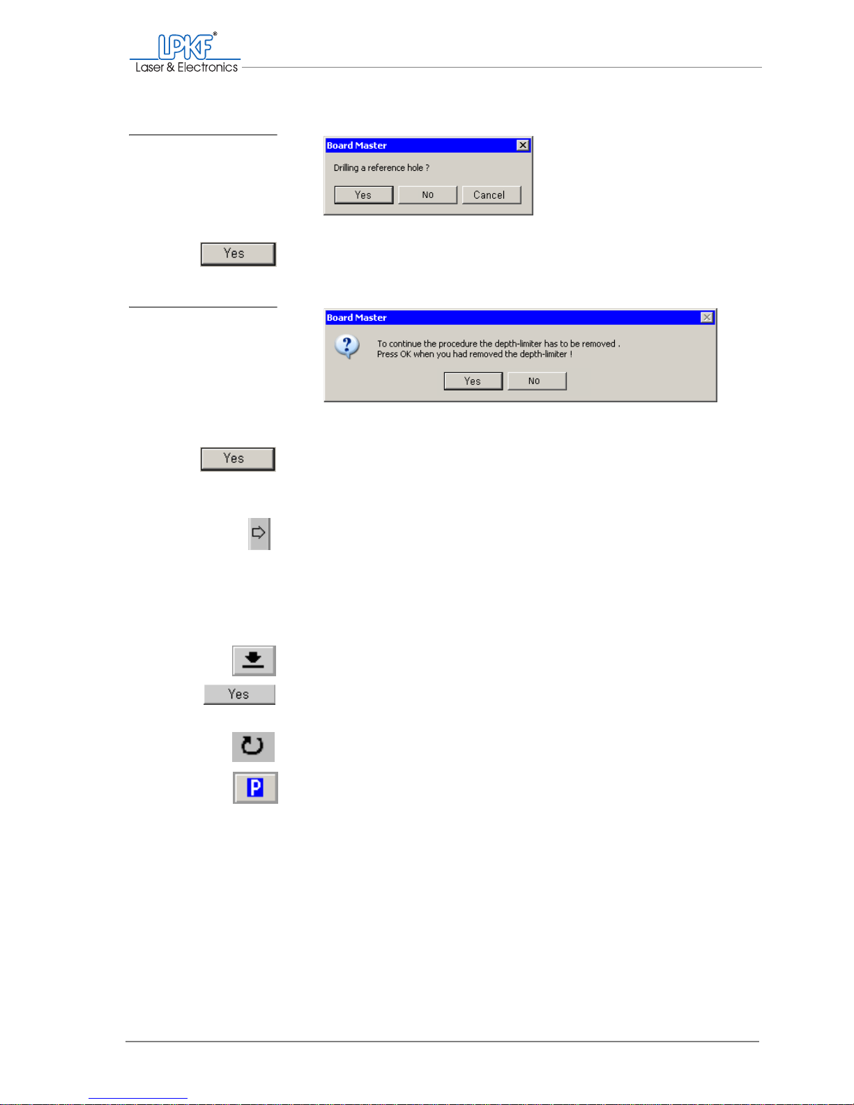
Manual tasks and settings
Operating Manual 7.1 Rev.: 18.06.2008 85
6. Click on Yes.
A prompt asking if the depth limiter has been removed appears.
7. Check that the plastic base has been removed from the milling
depth limiter and click on Yes.
The pass hole will be drilled.
8. Move the milling/drilling head using the Move to x+ button, so that
it is located in the desired position above the right-hand pass hole
strip.
Take care not to move the milling/drilling head in the Y direction,
otherwise the pass hole will not be positioned exactly on the mirror
axis.
9. Make a note of the x value used.
10. On the function bar, click on the Lower head button.
11. Confirm the prompts with Yes.
The pass hole will be drilled.
12. On the function bar, click on the Motor off button.
13. On the menu bar, click on the Move to pause button.
14. Remove dust and swarf with a brush.
15. Place the sinter plate on the vacuum table.
[ ] Now you can drill the pass holes into the sinter plate.
Fig. 35: BoardMaster mes-
sage "Drill pass
hole?"
Fig. 36: BoardMaster mes-
sage "Depth limit-
er removed"
Page 88
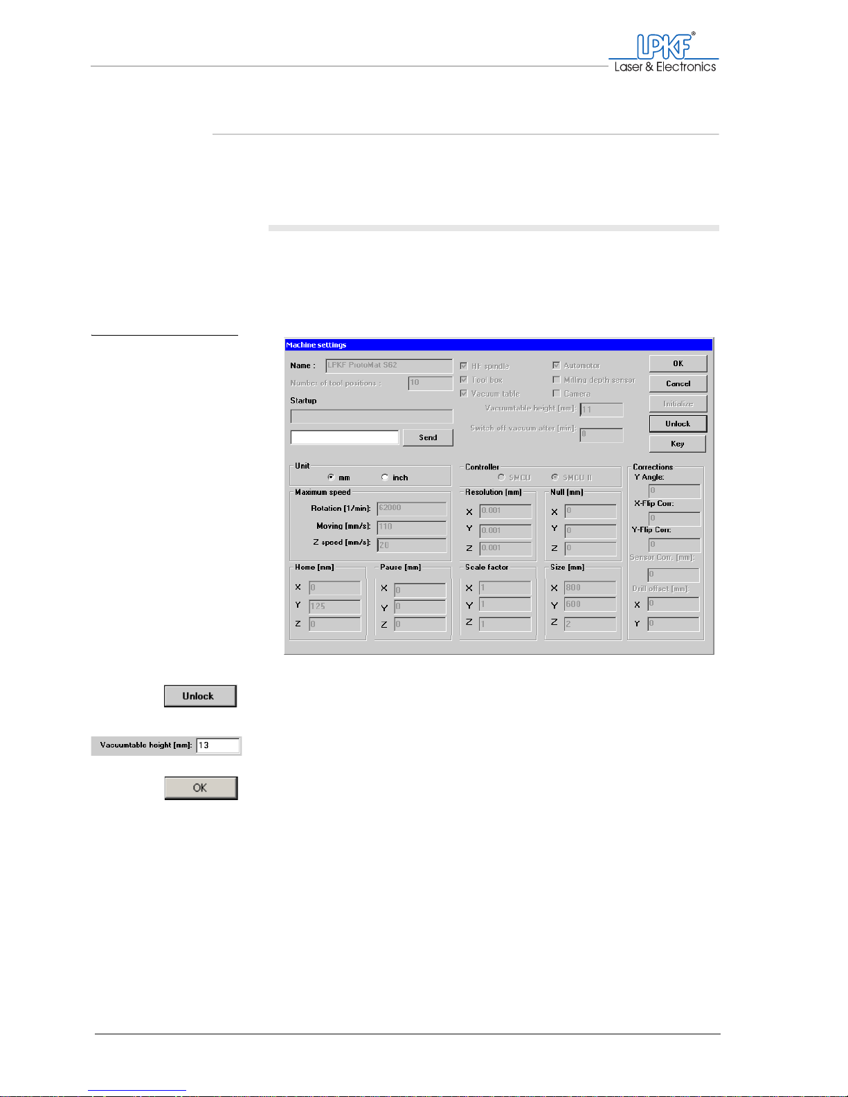
For your notes
86 ProtoMat®S62
4.12.2 Drilling pass holes into the sinter plate
Before drilling pass holes into the sinter plate, the machine parameters
have to be adjusted.
I.
Adjusting machine parameters
1. Put the the sinter plate on to the vaccum table.
2. On the menu bar, select Configuration > Settings... .
The Machine settings window opens.
3. Click on Unlock to allow the settings to be changed.
4. In the Vacuumtable height [mm] input box enter the value 13.
5. Click on OK.
[]
Fig. 37: Machine
parameters
Page 89
Manual tasks and settings
Operating Manual 7.1 Rev.: 18.06.2008 87
II. Drilling pass holes into the sinter plate
1. On the function bar, click on the tool selection list and select the
entry 2. Spiral Drill Ref 2.95 mm.
2. On the function bar, click on the Move to home button.
3. On the function bar, click on the Motor on button.
The milling/drilling spindle and the dust extraction start up.
4. On the function bar, click on the Lower head button.
5. Confirm both prompts with Yes.
The pass hole is drilled and the milling/drilling head is lifted automatically.
6. Using the Move to x+ button, move the milling/drilling head so that
it is located in the desired position above the right-hand pass hole
strip.
Take care not to move the milling/drilling head in the Y direction (if
you do this the pass hole will not be positioned in the centre of the
mirror axis).
7. On the function bar, click on the Lower head button.
8. Confirm the prompts with Yes.
The pass hole is drilled and the milling/drilling head is lifted automatically.
9. On the function bar, click on the Motor off button.
Fig. 38: Selecting pass
hole drills for pass
hole strips
Page 90

Inserting pass hole pins
88 ProtoMat®S62
10. If the dust extraction does not shut down automatically, click on the
Vacuum off button on the function bar.
11. On the menu bar, click on the Move to pause button.
The milling/drilling head moves to the pause position.
12. Remove any swarf with a brush.
13. Remove the sinter plate from the vacuum table.
[ ] To complete the pass hole system, you simply need to insert the pass hole
pins (see "Inserting pass hole pins") and mount the plastic base on the
milling depth limiter(see "Mounting the plastic base/brush head" on
page 63).
4.13 Inserting pass hole pins
Only use pass hole pins designed for your equipment configuration.
Note: For inserting the pass hole pins into the vacuum t able, the sinter plate h as
to be taken off.
Equipment Pass hole pins
Basic equipment: 3 mm x 8 mm
Vacuum table 3 mm x 10 mm
Page 91
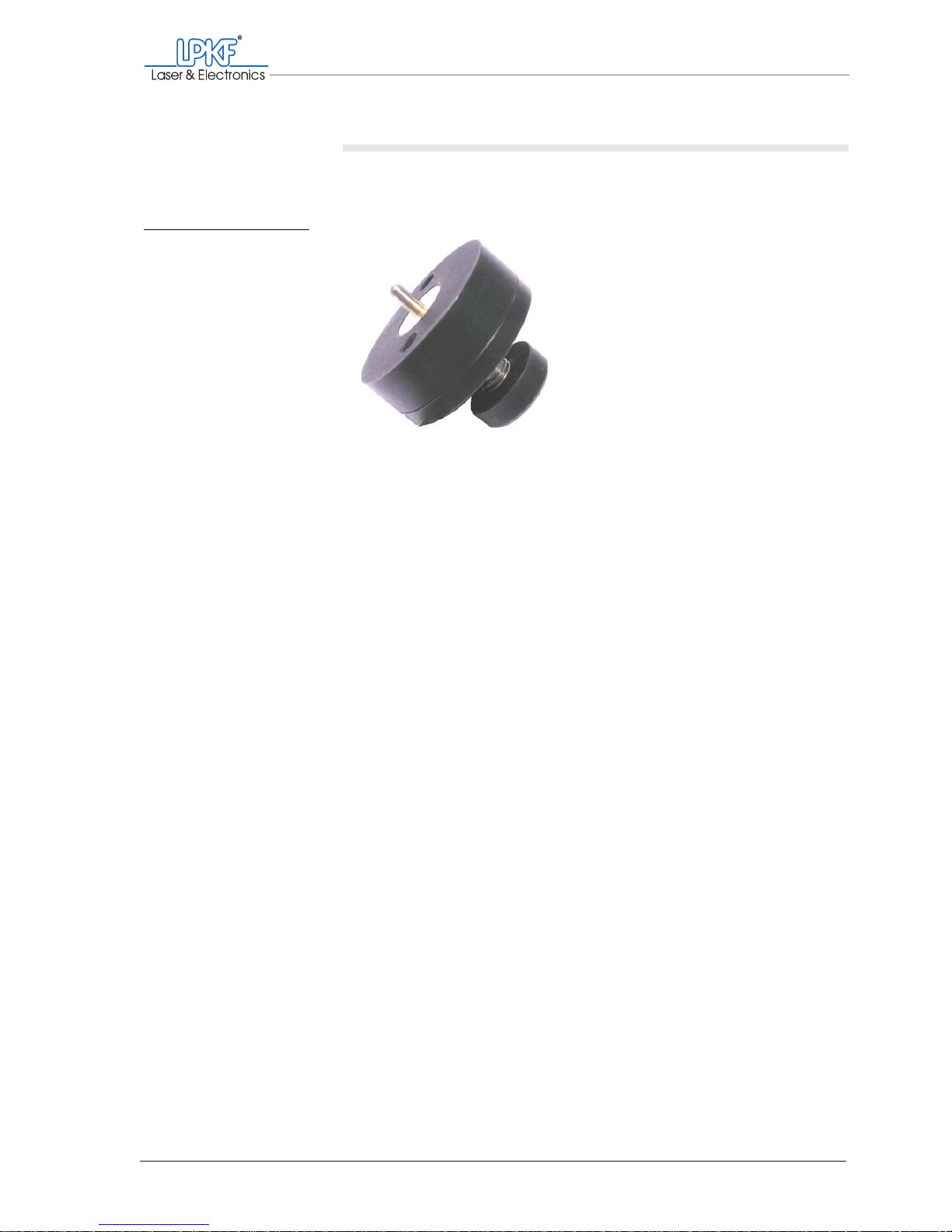
Manual tasks and settings
Operating Manual 7.1 Rev.: 18.06.2008 89
Inserting pass hole pins
1. Insert a pass hole pin with the rounded end into the press-in tool
(the bevelled end must stick out).
2. With the press-in tool press the pass hole pin as far as it will go into
the desired bore of the pass hole strip.
3. Check the pass hole pin for a snug fit in the pass hole strip.
4. Repeat the procedure to fit the pass hole pin in the second pass
hole strip.
5. Set the drilling underlay/sinter plate down on the traversing
table/vacuum table so that the pass hole pins slot into the bores.
6. Check that the pass hole pins do not protrude from the drilling
underlay/sinter plate any further than the thickness of the base
material.
You might need to press the pass hole pins further into the pass
hole strip.
7. Mount the plastic base on the milling depth limiter before resuming
work with the circuit board plotter (s. page 63).
[]
Fig. 39: Press-in tool with
pass hole pin
Page 92

Inserting pass hole pins
90 ProtoMat®S62
Page 93
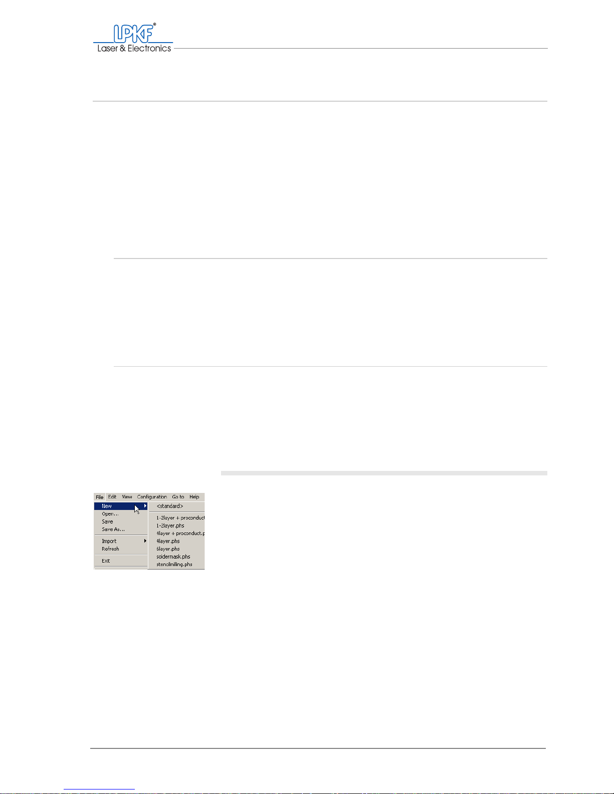
Working sequence in automatic mode
Operating Manual 7.1 Rev.: 18.06.2008 91
5. Working sequence in automatic mode
This chapter explains the fundamental working sequence for the semi-automatic production of
single-layer and multi-layer printed circuit boards. It can vary depending on the production type
and equipment of your ProtoMat
®
S62 and your individual requirements. If you are working with
the LPKF circuit board plotter for the first time, we recommend that you start by practising the
procedures described with the example files included in the delivery.
Knowledge of how to operate the circuit board plotter manually and the most important BoardMaster functions is assumed (see chapter 4‚ "Manual tasks and settings", on page 47).
5.1 Preparation
The following information assumes that the ProtoMat®S62 is switched
on, the material to be processed is fixed on the traversing/vacuum table
and the work area has been set up in BoardMaster. (see chapter 4.6.1‚
"Loading and setting up the base material", on page 64).
5.2 Defining the production type
The ProtoMat®S62 is factory-set for the production of single-sided or
double-sided printed circuit boards with galvanic through-hole plating.
The phase file 1-2layer.phs (<default>) is used for such applications.
To create a different production type, you will need to select the corresponding phase file.
Selecting a phase file
1. Click on File > New and select the phase file provided for the pro-
duction type (see table 6).
Page 94

Setting up a job
92 ProtoMat®S62
Tab. 6: Production types and phase files
[ ] The required production phases are displayed in the phase selection (see
Tab. 3 "Production phases" on page 40).
5.3 Setting up a job
A job contains all data and information required for production. You can
open and edit an existing job, or create a new one.
Note: The items listed below correspond to the standard production of a singlesided or double-sided printed circuit board with galvanic through-hole plating
(1-2layer.phs).
To set up a new job, you first need to import a project (LMD file). However, you can also open an existing job and add further projects to it.
Information about the
example files
• You can use the Tutor.LMD project to produce a double-sided prac-
tice printed circuit board.
• Fiducial.LMD contains information for drilling a fiducial (only needed
if you are using the VisionSystem).
Production type Phase file
Single-sided/double-sided printed circuit
boards
(galvanic through-hole plating)
1-2layer.phs (<default>)
Single-sided/double-sided printed circuit
boards
(galvanic through-hole plating with LPKF
ProConduct)
1-2layer + proconduct.phs
4-layer multi-layer
(galvanic through-hole plating)
4-layer.phs
4-layer multi-layer
(galvanic through-hole plating with LPKF
ProConduct)
4-layer + proconduct.phs
6-layer multi-layer 6-layer.phs
Solder stop foils soldermask.phs
Solder paste stencils stencilmilling.phs
Page 95
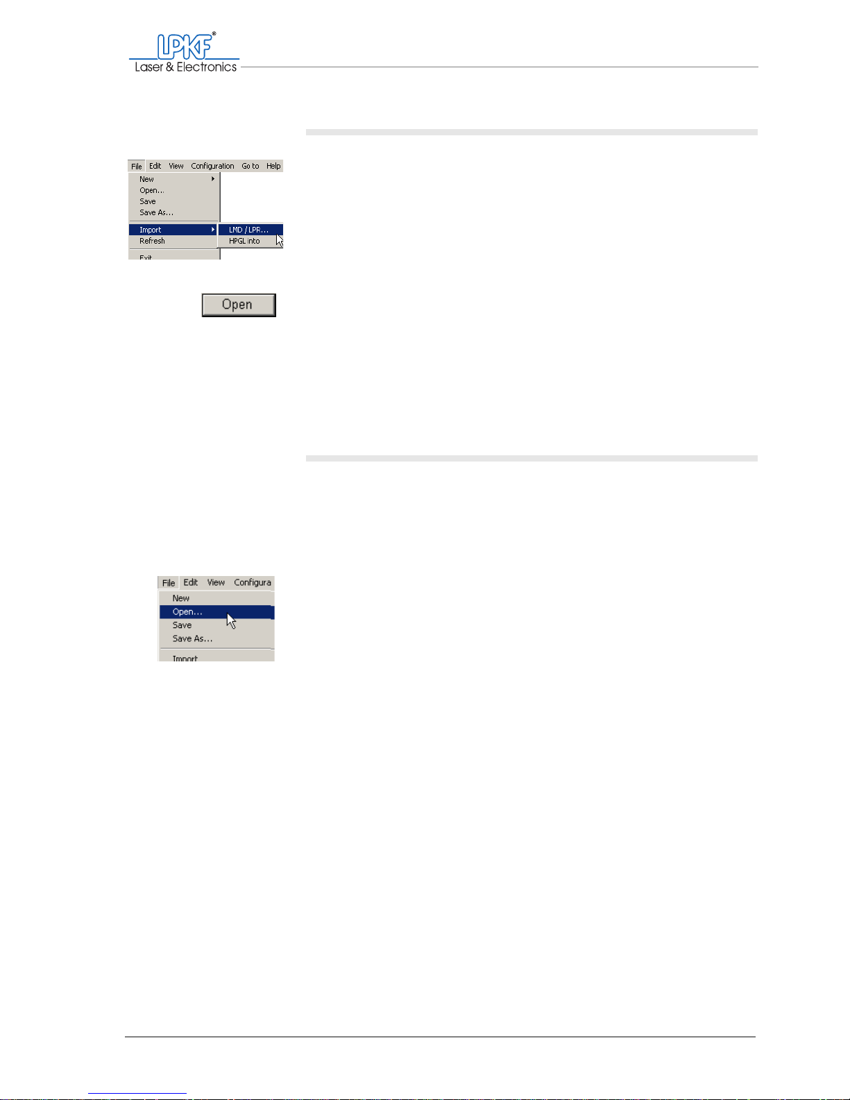
Working sequence in automatic mode
Operating Manual 7.1 Rev.: 18.06.2008 93
Creating a new job
1. Click on File > Import > LMD/LPR....
The Import Project window will appear.
2. Select a project (*.LMD file).
3. Click on Open.
The selected project will be placed in the centre of the work area.
4. Import other projects if you need them,
for example fiducial bores for automatic fiducial recognition (only
with the optional VisionSystem).
The imported projects can be moved and copied on the work area.
Opening an existing job
If already a job is open, you first have to decide whether you wish to
save any changes under a different name (see "Saving a job" on
page 95).
Once you have called the File > Open... menu item, an already opened
job can only be overwritten or the changes discarded.
1. Click on File > Open....
The Open window is displayed.
2. Double-click on the required *.job file.
Select for example Tutor.job to open the production example
included in the delivery.
[ ] The projects contained in the job can be moved, copied or deleted on the
work area.
Page 96
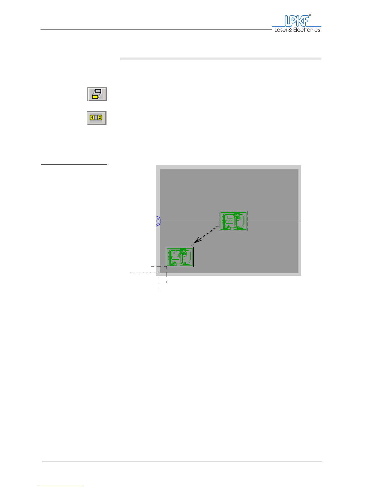
Setting up a job
94 ProtoMat®S62
Aligning/Distributing projects
To make optimum use of the base material, you can align, distribute
and duplicate projects individually.
1. On the function bar, click on the Move instance button to move a
project on the work area.
or:
On the function bar, click on the Copy instance button to copy a
project and move the copy on the work area.
2. Drag the project to be moved with the left mouse button pressed to
the desired position on the work area. Make sure that the distance
between the project and the edges of the base material is at least
12 mm.
[ ] The project will be positioned where the mouse button is released.
Note: It is also possible to align a project exactly on reference points, rotate and scale it and define it as a multiple panel. To do this, use the Edit >
Placement... menu item.
Fig. 40: Positioning a
project
12 mm
12 mm
Page 97
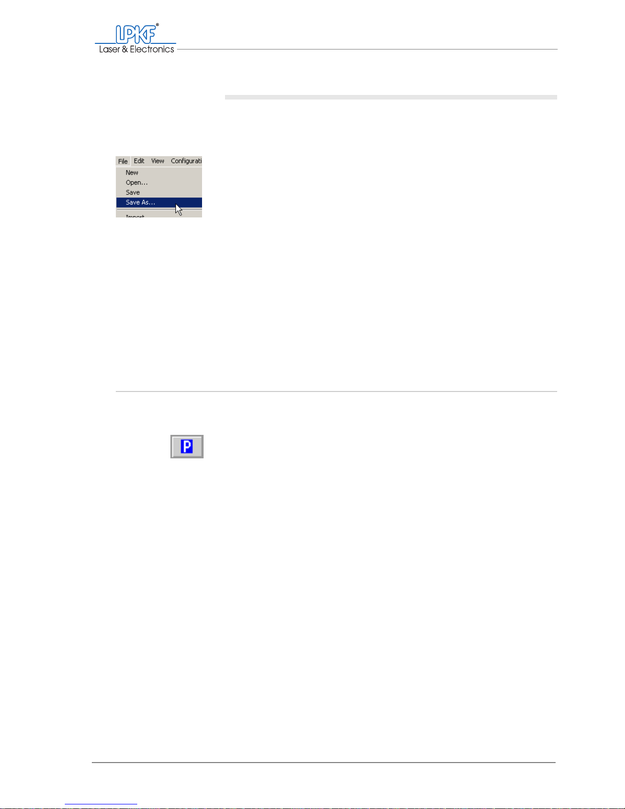
Working sequence in automatic mode
Operating Manual 7.1 Rev.: 18.06.2008 95
Saving a job
If you have have set up an already existing job, you can save it under a
different name or the current version can be overwritten.
1. To save the job under a new name:
Click on File > Save as....
The Save as window will open.
2. Enter a meaningful name for the job in the File name box.
3. Click on Save.
[ ] The job will be saved under the desired name.
4. To save the job under the current name and discard the previous
version:
Click on File > Save.
[ ] The changed job will be saved under the previous name.
5.4 Setting up the tools
BoardMaster assists you in setting up the tools by displaying the tools
required for production in the Tool Positions window.
Before loading the tool magazine, make sure that the milling/drilling hea d
is in the pause position.
Note: The entries listed below correspond to the standard production of a singlesided or double-sided printed circuit board with galvanic through-hole plating
(1-2layer.phs).
Page 98
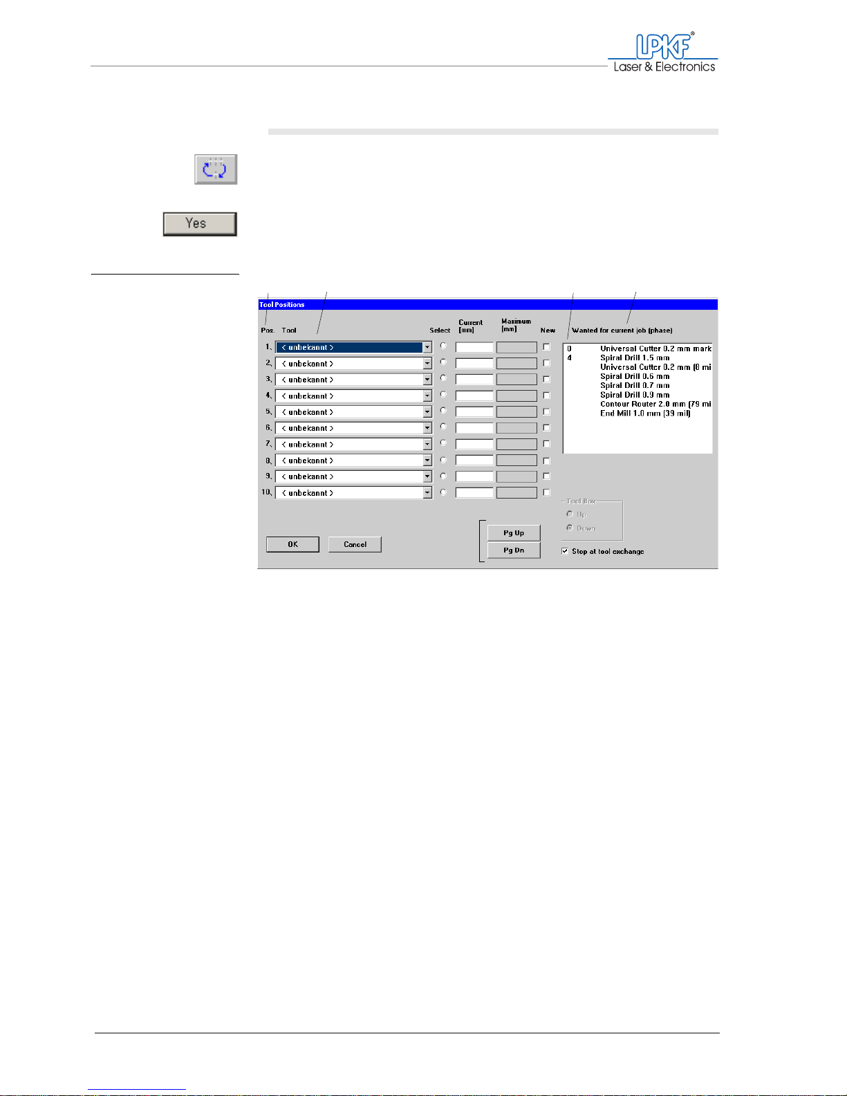
Setting up the tools
96 ProtoMat®S62
I. Opening the Tool Positions input window
1. Click on the Toolbox dialog button.
2. Click on Yes to move the milling/drilling head to the pause position.
The Tool Positions input window opens.
The tool magazine can hold up to 10 tools. The positions specified on the
left of the dialogue box under Pos. correspond to the arrangement of the
tool holders from left (position 1) to right (position 10) in the tool magazine.
Y ou can select one tool for each of the corresponding p ositions in the tool
magazine in the tool selection lists under Tool . Each selection list contains all available tools.
Fig. 41: Tool Positions input
window
1 Position in the tool magazine
2 Tool selection lists
3 Service life of the tools required for the current
phase
4 Tools required for the duration of production
12
3
4
Page 99
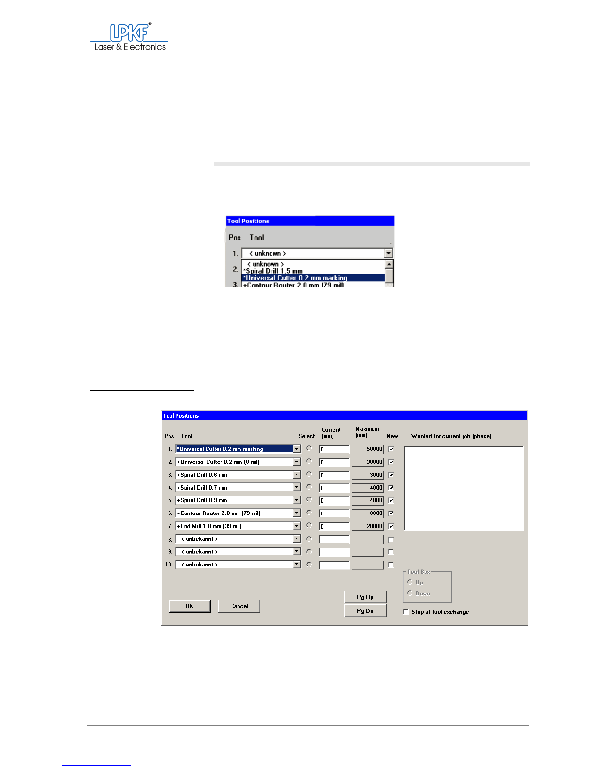
Working sequence in automatic mode
Operating Manual 7.1 Rev.: 18.06.2008 97
The tools required for the job are displayed in the Wanted for current
job (phase) box. The preceding numbers designate the tools required for
the current phase (displayed on the function bar). The numerical value
indicates the service life required for the job in mm (milling cutter) or the
number of bores (drill).
II.
Configuring tools in the tool magazine
1. Select one of the required tools for each position (Pos.) from the
Tool selection list .
Note: The tools required for the currently selected production phase are
marked with an *; the tools required for other production phases are
marked with a +.
Once you have assigned a tool position to each of the required tools, the
input window could look like this:
Fig. 42: Assigning tool po-
sitions
Fig. 43: Defined tool positions
Page 100
Setting up the tools
98 ProtoMat®S62
Note: The order of the tool positions can be selected at will. During operation, the tools are taken out of the correct tool holder automatically.
2. To adjust the manual milling depth setting after each tool change
during a production phase:
Activate the Stop at tool exchange checkbox.
[ ] Initially, keep the window open to insert the tools into the tool magazine
according to your settings.
III. Inserting tools
1. With the tip pointing downwards, push the required tools as far as
they will go into the tool holders (positions) defined in the Tool
Positions window.
Note: Position 1 is on the left-hand side of the tool magazine, position 10
is on the right.
2. Close the acoustic cabinet cover.
3. Click on OK.
[ ] The tools defined in the Tool Positions input window are displayed in the
tool selection list on the function bar.
WARNING
Risk of injury!
The tools to be used are very sharp edged and can cause cuts
and stab injuries.
› Handle tools carefully and keep them in the toolbox when not
in use.
CAUTION
Material damage due to incorrect loading!
If you insert the tools into other positions than those defined by
BoardMaster, the milli ng/drilling head and spindle and the tools
can become damaged.
› Insert the tools only into the tool holder (positions) defined by
BoardMaster.
 Loading...