

Page 1
Manual ProtoMat C30/C 30-S
English, version 1.0
LPKF Laser & Electronics AG
Osteriede 7
D-30827 Garbsen
Telefon : ++ 49 - 51 31 - 70 95 - 0
Telefax : ++ 49 - 51 31 - 70 95 - 90
eMail : [email protected]
Homepage : http: //www.lpkf.de
Page 2

2 ProtoMat C30/C30-S
Copyright (c) 2000 LPKF AG
Distribution or reproduction of this manual and use of its content
permitted only with the written approval of LPKF AG. Right to make
modifications reserved. No liability is accepted for the content. In
particular, we accept no liability for damage caused by information given,
information absent, or erroneous information.
Trademarks: HP-GL is a registered trademark of the Hewlett Packard
Corporation. All other trademarks are registered by their owners.
Page 3

ProtoMat C30/C30-S 3
Information on this manuel
The information contained in this document may be modified without
prior notification. No part of this document may be reproduced or
transmitted for any purpose or in any form by any means, electronic or
mechanical, by photocopy, by recording or by information storage and
information retrieval systems without the express written permission of
LPKF.
We have taken great trouble to ensure the accuracy and completeness
of the information in this document. However, LPKF accepts no liability
for the use of the document, including breach of copyright or other
infringement against third parties which may arise from this.
It is the duty of the system owner to care for and plan these measures as
well as to control their execution. The owner especially has to ensure
that
• the system is only used as directed
• the system is only operated in perfect and functional
condition. Especially the function of the safty appliances
has to be checked regularly
• the necessary personal protectiv equipment for the
operating, maintaining and repairing personnel is available
and being used
• the operating manual is kept legible and complete at the
place of operation
• only sufficiently qualified and authorized personnel
operates, maintains and repairs the system
• this personnel is regularly instructed in matters of work
safety and environmental protection and is informed on the
operation manuel and especially the safety instructions
• all safety and warning notes or signs stay on the system and
are legible
Page 4
4 ProtoMat C30/C30-S
Using this manual
I. Orientation
This manual is divided into the following chapters:
1.
Safty notes
2.
Introduction
3.
General Information
4.
Setup
5.
Operating displays
6.
Computer-controlled functions
7.
Tools and accessories
8.
Milling and drilling
9.
Appendix
10.
Declaration of conformity
11.
Index
II. Conventions used in this manual
Bold text
is used to emphasise important information.
Illustrations
are numbered. Example: Fig. 5
› Prompts for actions are identified with an arrow.
Italic sections
are used to indicate the reactions consequent on an
action.
Words printed in italics
mark proper names
Key inscriptions and menu terms are printed in
BOLD CAPITALS
.
III. Notes on the symbols used
Danger!
This symbol is used to highlight danger to life or health.
Caution!
This symbol is used to identify hazards which may cause
damage.
Note:
This symbol is used for notes intended to help you avoid faults in
operation or to help you improve your procedures.
Page 5

ProtoMat C30/C30-S 5
III. Legend
Copper laminate:special, very thin basis material used only for
laminating multilayer boards
Basis material: carrier material of thr main board, coated with a copper
foil
Solder foil: special foil for cutting aperatures for the connections to
be soldered
BoardMaster
: Machine control software
CircuitCAM
: Software for data preparation
IV. Target Group
This manuel is written for people with basic knowledge in PCB
production.
Page 6

6 ProtoMat C30/C30-S
Table of contents
1.0 Introduction. . . . . . . . . . . . . . . . . . . . . . . . . 10
1.1 LPKF ProtoMat C30 (C30/S) machine ratings
. . . .10
2.0 Safty Notes . . . . . . . . . . . . . . . . . . . . . . . . . 11
3.0 General information . . . . . . . . . . . . . . . . . . 12
3.1 Scope of supply
. . . . . . . . . . . . . . . . . . . . . . . . . . .12
3.2 Optional accessories
. . . . . . . . . . . . . . . . . . . . . . .12
3.3 Air-borne sound
. . . . . . . . . . . . . . . . . . . . . . . . . . .12
3.4 Installation
. . . . . . . . . . . . . . . . . . . . . . . . . . . . . . .13
4.0 Computer-controlled functions. . . . . . . . . 14
4.1 Connection to a PC
. . . . . . . . . . . . . . . . . . . . . . . .14
4.2 Machine orientation
. . . . . . . . . . . . . . . . . . . . . . . .15
4.3 Displays and connections
. . . . . . . . . . . . . . . . . . . .16
4.4 Functional elements on the plotter head
. . . . . . . .18
5.0 Use of LPKF BoardMaster . . . . . . . . . . . . . 19
6.0 Setup . . . . . . . . . . . . . . . . . . . . . . . . . . . . . . 20
6.1 Switch-on sequence
. . . . . . . . . . . . . . . . . . . . . . . .20
6.2 After switching on
. . . . . . . . . . . . . . . . . . . . . . . . . .20
7.0 Functional test with LPKF BoardMaster. . 21
7.1 HOME position and registration hole system
. . . . .22
Page 7

ProtoMat C30/C30-S 7
7.2 Checking and correcting the HOME position
. . . . .22
7.3 Programing the HOME position in
LPKF BoardMaster
. . . . . . . . . . . . . . . . . . . . . . . . . . . .26
7.4 Creating a new registration hole system
. . . . . . . .27
8.0 Tutorial on creating a printed circuit board30
8.1 Reprogramming the machine data
. . . . . . . . . . . . .32
9.0 Tools, material and accessories. . . . . . . . 34
9.1 Tools
. . . . . . . . . . . . . . . . . . . . . . . . . . . . . . . . . . . .34
9.2 Materials used for machining
. . . . . . . . . . . . . . . . .35
10.0 Procedures for milling and drilling . . . . 37
10.1 Securing the board
. . . . . . . . . . . . . . . . . . . . . . . .37
10.2 Operating the working depth limiter
. . . . . . . . . . .38
10.3 Changing a tool (C30)
. . . . . . . . . . . . . . . . . . . . .39
10.4 Changing a tool (C30/S)
. . . . . . . . . . . . . . . . . . . .39
10.5 Drilling
. . . . . . . . . . . . . . . . . . . . . . . . . . . . . . . . . .40
10.6 Isolation milling . . . . . . . . . . . . . . . . . . . . . . . . . . .
40
10.7 Contour milling in base material
. . . . . . . . . . . . . .41
10.8 Milling wide isolation channels and rubouts
. . . . .42
10.9 Front plate engraving
. . . . . . . . . . . . . . . . . . . . . .42
10.10 Milling solder-stop sheets
. . . . . . . . . . . . . . . . . .43
10.11 Milling layout films
. . . . . . . . . . . . . . . . . . . . . . . .43
10.11.1 Staining milled films . . . . . . . . . . . . . . . . . . . . . 44
Page 8

8 ProtoMat C30/C30-S
10.11.2 Removing the coating. . . . . . . . . . . . . . . . . . . . 44
11.0 Tool libraries in BoardMaster . . . . . . . . . 46
11.1 Cleaning the board
. . . . . . . . . . . . . . . . . . . . . . . .47
12.0 Practical tips . . . . . . . . . . . . . . . . . . . . . . . 48
13.0 Appendix . . . . . . . . . . . . . . . . . . . . . . . . . . 50
13.1 Maintenance
. . . . . . . . . . . . . . . . . . . . . . . . . . . . .50
13.1.1 Working depth limiter . . . . . . . . . . . . . . . . . . . . . 50
13.2 Lubricating the carriage guide wipers
. . . . . . . . . .51
13.2.1 Carriage guide wipers of the Y-axis . . . . . . . . . . 52
13.2.2 Carriage guide wipers of the X-axis . . . . . . . . . . 53
13.2.3 Oiling the rear wipers . . . . . . . . . . . . . . . . . . . . . 53
13.2.4 Oiling the front wipers. . . . . . . . . . . . . . . . . . . . . 54
13.3 SerialPort 1 serial connection
. . . . . . . . . . . . . . . .54
13.4 SerialPort2 serial connection
. . . . . . . . . . . . . . . .55
13.5 Connecting the stepping motors
. . . . . . . . . . . . . .55
13.6 Connecting the plotter head
. . . . . . . . . . . . . . . . .55
13.7 EPROMs
. . . . . . . . . . . . . . . . . . . . . . . . . . . . . . .56
13.8 Switching the device voltage,
electrical fuses
. . . . . . . . . . . . . . . . . . . . . . . . . . . . . . . .56
13.9 Removing the electronics unit
. . . . . . . . . . . . . . .57
13.10 The Command set
. . . . . . . . . . . . . . . . . . . . . . .59
13.10.1 Command structure . . . . . . . . . . . . . . . . . . . . . 59
13.10.2 HP-GL standard commands. . . . . . . . . . . . . . . 60
13.10.3 Special commands. . . . . . . . . . . . . . . . . . . . . . 61
13.10.4 Special command for the motor controller . . . . 63
Page 9

ProtoMat C30/C30-S 9
13.10.5 Direct commands . . . . . . . . . . . . . . . . . . . . . . . 63
13.11 Table of available tools
. . . . . . . . . . . . . . . . . . . .65
14.0 Concluding remarks . . . . . . . . . . . . . . . . 66
15.0 Konformitätserklärung für LPKF ProtoMat
C30 (C30/S) . . . . . . . . . . . . . . . . . . . . . . . . . . . . 67
15.1 Declaration of conformity
. . . . . . . . . . . . . . . . . . .68
16.0 Index . . . . . . . . . . . . . . . . . . . . . . . . . . . . . 69
Page 10

Introduction
10 ProtoMat C30/C30-S
1.0 Introduction
The LPKF
ProtoMat C30 (C30/S)
circuit-board plotter is a system for the
production of circuit board prototypes and engraving films, and for
engraving aluminium or plastic.
It is essential that you familiarize yourself with the functions of the LPKF
BoardMaster
driver program before using the plotter. You will find a
description of the driver program's functionality in the manual for the
LPKF
BoardMaster
. The operating interface for the LPKF
ProtoMat C30
(C30/S)
is a PC.
It is absolutely vital that you read the instructions given in this manual
before putting the machine into operation, otherwise you will invalidate
any warranty claims. The appropriate national warranty provisions apply
for machines exported to other countries of the European Community.
1.1 LPKF ProtoMat C30 (C30/S) machine ratings
Voltage 200-240V (or 100-120V)
Power input 150VA
Speed of plotter spindle DC motor,
5000 - 32,000/min (variable)
Weight approximately 24 kg
Drilling performance 78 lifts/min maximum
Resolution (smallest increment) 7.9375 µm (0.3125 mil)
Operating data:
Humidity 60% max.
Temperature: 15-25°C
Page 11

Safty Notes
ProtoMat C30/C30-S 11
2.0 Safty Notes
In order to be able to guarantee the safe operation of the system
the user must have read this manual and especially the safety
precautions printed in bold types!
• Never reach into the machine while it is running!
• Remember that the machine changes speed automatically
during the process!
• Only change the tool when the mill/drill motor is not
spinning!
• Insert the tool into the clamping device as far as it will go!
• Never operate the control PC simultaneously when working
with the device!
• Operator with longer hair must wear a hair net!
• If you modify the equipment yourself, the equipment's safety
can no longer be guaranteed and no guarantee claims can
be accepted!
• Please take note that some materials may produce
cancerogenous dust or hazardous gases. Ask your supplier
of the materials.
• Always work with the vacuum device!
• When using chemicals please take note of the safety notes
on the containers or separate security sheets delivered with
them!
• Keep the workplace tidy.
Page 12

General information
12 ProtoMat C30/C30-S
3.0 General information
3.1 Scope of supply
1.
One LPKF
ProtoMat C30 (C30/S)
machine unit with integrated
electronics
2.
One null modem cable (LPKF
ProtoMat C30 (C30/S)
control unit to
computer), 9/25-pin AT-adapter
3.
One set of accessories (adhesive tape, various Allen keys, 5
alignment pins, tweezers, brush, 7 mm box spanner, two red
registration hole strips, syringe containing oil, 2 alignment drill
2,95 mm)
4.
One mains cable
5.
Inserting tool for alignment pins
6.
This manual
3.2 Optional accessories
The following accessories are available for the LPKF
ProtoMat C30
(C30/S)
:
1.
Vacuum system with fine mesh filter.
The fine mesh filter is particularly essential when handling materials
containing glass fibre, such as FR4 base material.
2.
Noise and dust protective hood
3.
LPKF
AutoSwitch
.
Automatic switch for the vacuum system. This option allows the
vacuum system to be switched on and off by the plotter spindle.
4. ZelSpot
.
Illuminates the plotter head.
5.
LPKF
AutoContac
Integrated through-hole plating using a dispenser and a special
conductive paste capable of being soldered.
3.3 Air-borne sound
There is a continuous sound pressure level of 71 dBA at the workstation
during operation.
This value does not include the vacuum unit.
Page 13
General information
ProtoMat C30/C30-S 13
3.4 Installation
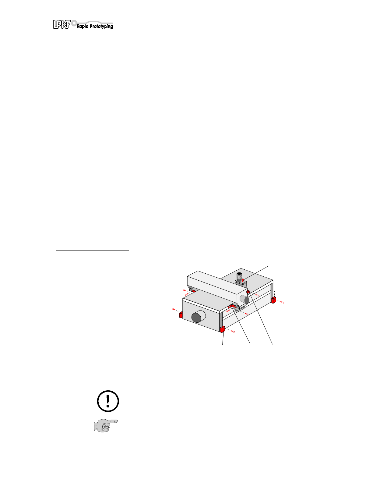
› Unpack the LPKF
ProtoMat C30 (C30/S)
carefully. Remove the
securing bolts. (see securing bolt 1 in the drawing)
• Securing device (M5 x 25, 4.5 x 60 screws)
Now loosen the transport securing devices. The transport securing
devices are located:
• To secure the X axis - (securing device 2) angle brackets on each
side of the machine's base plate M4 x 10 screws
• To secure the Y axis - (securing device 3) on the left-hand side of
the plotter head M4 x 40 screws
• To secure the Z axis - (securing device 4) on the plotter head
M4 x 20 screw
Set up the circuit-board plotter so that the cables connecting the
electronics unit are free to move.
› Connect the LPKF
ProtoMat C30 (C30/S)
to COM1 or COM2 on the
computer using the null modem cable.
› Plug the LPKF
ProtoMat C30 (C30/S)
control unit into the electricity
supply.
Fit the vacuum system onto the adaptor
(fits pipe no. 111124 on a Nilfisk industrial vacuum system).
fig. 1:
Caution! The machine must stand on a flat and firm base in order to
work correctly and without malfunctions.
Note: Keep all transport securing devices and reattach them
accordingly if the machine is to be shipped again. The packaging
should also be kept and used when the machine is returned for
servicing.
1- To secure themachine to the transportation base (M5 x 25, 4.5 x 60 screws)
2- To secure the X axis (M4 x 10 screws)
3- To secure the Y axis (M4 x 40 screw)
4- To secure the plotter head (M4 x 20 screw)
4
1
23
Page 14
Computer-controlled functions
14 ProtoMat C30/C30-S
4.0 Computer-controlled functions
4.1 Connection to a PC
The LPKF
ProtoMat C30 (C30/S)
has two serial ports. The first (25-pin)
is used for connection to the controlling computer (PC).
The second port (9-pin) is intended for future applications.
The 25-pin interface of the LPKF
ProtoMat C30 (C30/S)
control unit is
connected to a serial port on the computer with the null modem cable
supplied.
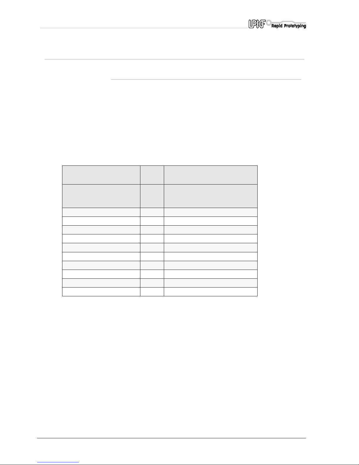
The RS232 (null modem) cable for the LPKF
ProtoMat C30 (C30/S)
circuit-board plotter is wired as follows:
The following parameters must be observed:
• Baud rate 9600(default setting, others upon request)
• Parity none
• Data bits 8
• Stop bit 1
• Handshake hardware
• FiFo buffer
enabled no
25-pin socket 25-pin socket
PC (COMx) Circuit-board plotter
(SerialPort1)
1 1
2TXD 3
3 RXD 2
45
5 4
77
8 GND 20
15,17 24
20 8
24 15,17
Page 15
Computer-controlled functions
ProtoMat C30/C30-S 15
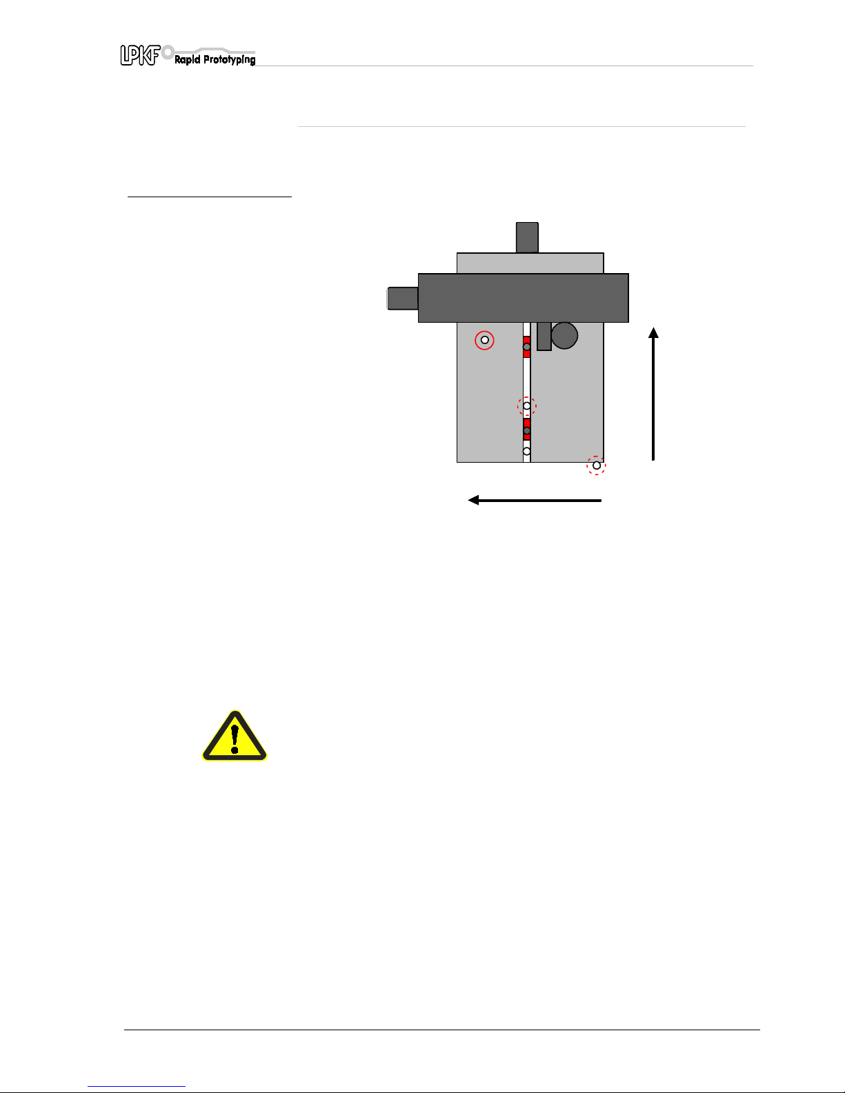
4.2 Machine orientation
Description of the machine's main positions:
fig. 2: LPKF ProtoMat C30 (C30/S):
The X axis has the greater
travel
Danger! Do not put fingers or any items into the movement range.
1
- PAUSE position.
The plotter head travels to this point to load or turn the material to be machined.
2
- HOME position.
This is on the plotter's axis of symmetry (registration hole system) and serves as the
reference position for the LPKF
BoardMaster
3
- Registration hole slide with hole for alignment pin
4
- Reference pin for the front registration hole strip. The front registration hole slide butts
against the stop.
5
- Tool change position (zero position).
The tool is changed here.
5
+ x
+ y
1
2
3
4
Page 16
Computer-controlled functions
16 ProtoMat C30/C30-S
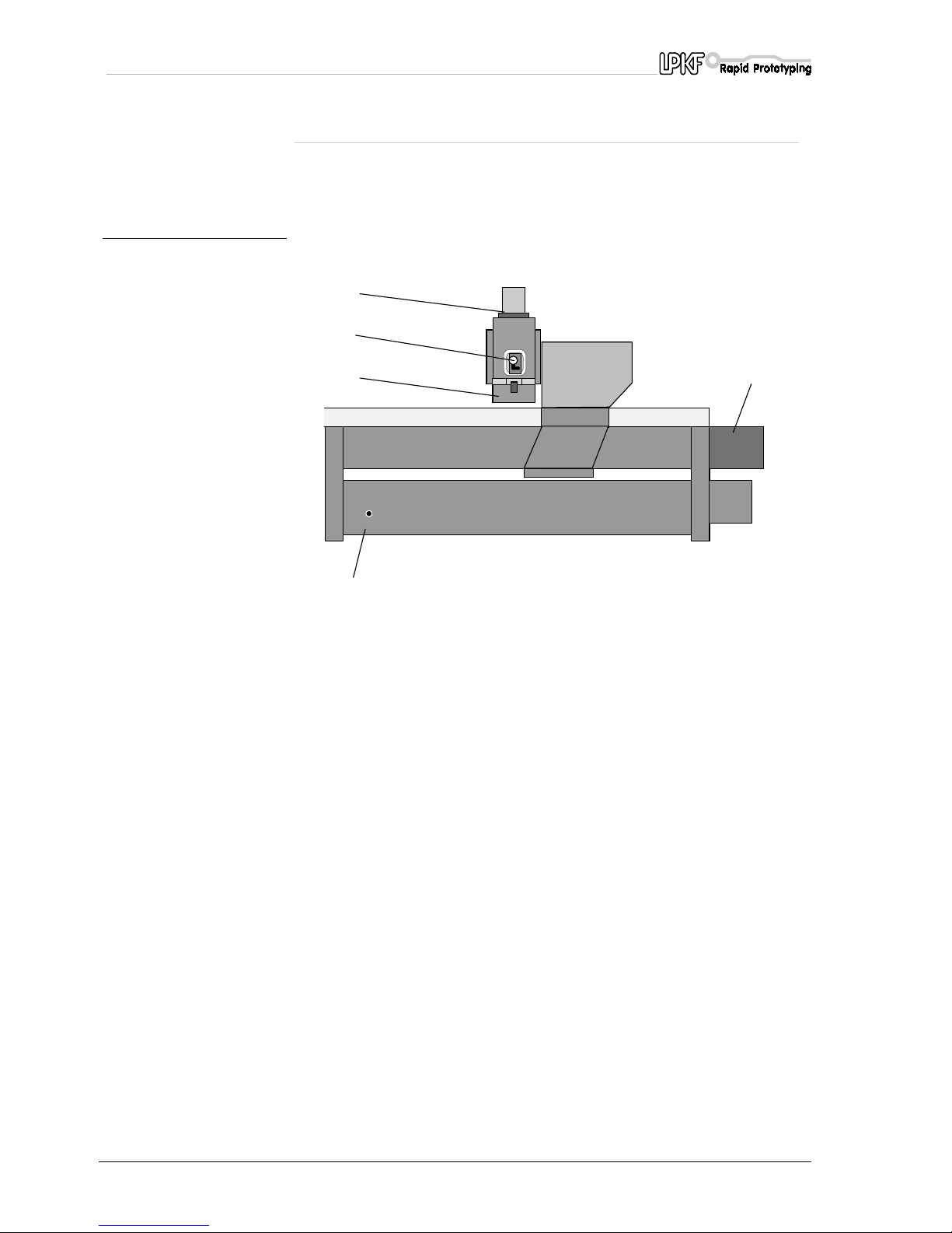
4.3 Displays and connections
Description of the front view:
fig. 3: Front view of LPKF ProtoMat
C30 (C30/S)
1
- Operating indicator for the integrated SMCU machine controller
2
- Motor for the longitudinal axis (X axis)
3
- Plotter spindle (DC motor)
4
- Lever for opening the tool collet (Only ProtoMat C30/S)
5
- Working depth limiter
POWER
LPKF
ProtoMat C30
3
4
2
5
Page 17
Computer-controlled functions
ProtoMat C30/C30-S 17
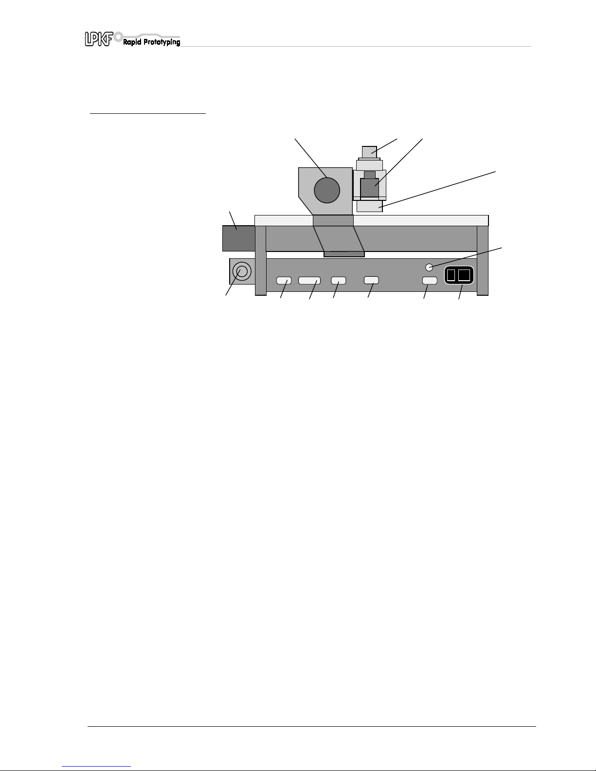
Description of the rear:
fig. 4: Rear view of the LPKF
ProtoMat C30 (C30/S)
1
- Vacuum system connection 8- X motor
2
- Serial port (9-pin) for expansion units 9- Y motor
3
- Serial port (25-pin) for connection to PC
10
- Plotter spindle (DC motor)
4
- X motor connection
11
- Solenoid actuator
5
- Y motor connection
12
- Working depth limiter
6
- Connection for plotter head and options
13
- DC motor connection
7
- On/Off switch with mains connector and fuses
10 11
23 7
9
12
8
1
4
5
6
13
IO
Page 18
Computer-controlled functions
18 ProtoMat C30/C30-S
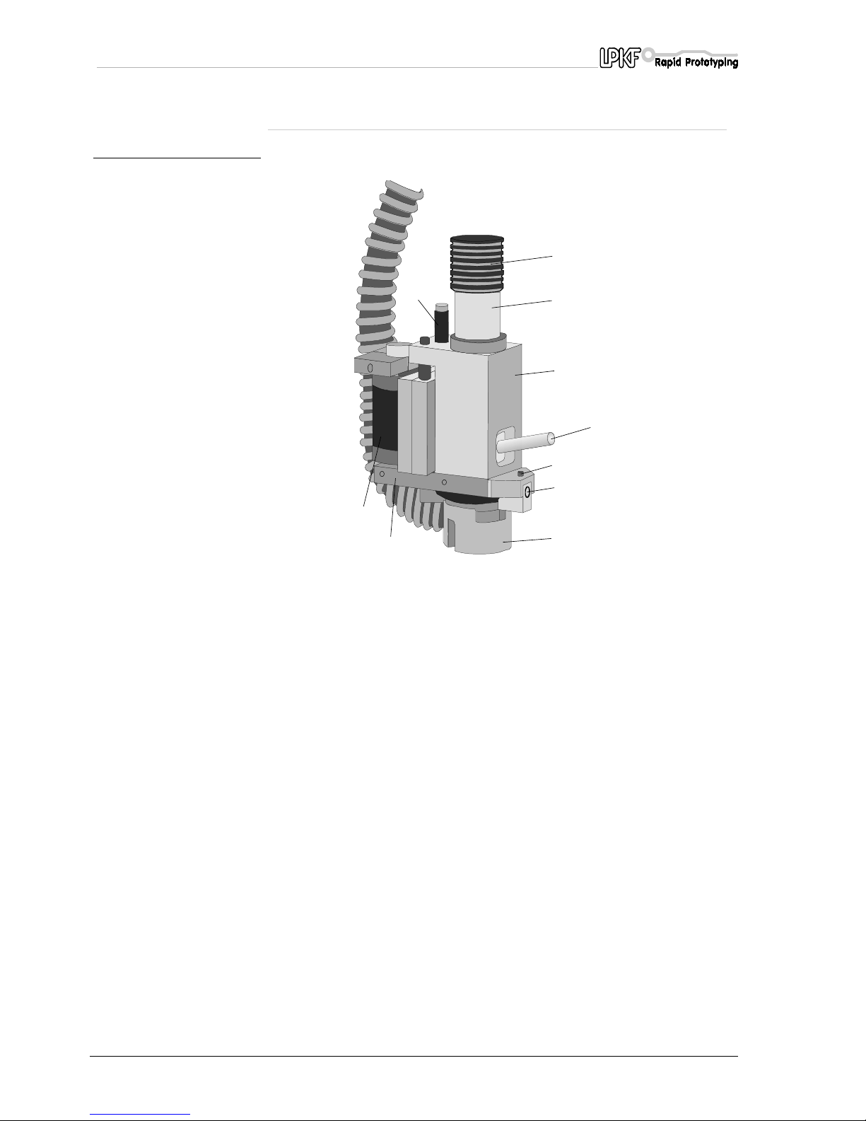
4.4 Functional elements on the plotter head
fig. 5: Front view of plotter head
1
- Shock absorber 6- Plotter spindle (DC motor)
2
- Lifting magnet 7- Bottom head stop adjustment
(Caution - do not adjust.)
3
- Working depth limiter 8- Fixing screw for working depth limiter
4
- Motor cover
9
- Plotter head base plate
5
- Mounting flange for the DC motor
10
- Lever for opening the tool collet
(Only ProtoMat C30/S)
4
9
3
1
7
8
10
5
6
2
Page 19

Use of LPKF BoardMaster
ProtoMat C30/C30-S 19
5.0 Use of LPKF BoardMaster
The data required to drive the plotters is generated by postprocessing
with LPKF
CircuitCAM
and is stored in a binary LPKF file (LMD format).
BoardMaster
now reads these files, decodes the plotter commands and
modifies them for the particular machine being driven.
This is necessary as although different machines may perform similar
operations, they nevertheless use different command sets.
The LPKF
ProtoMat C30 (C30/S)
circuit-board plotter is HP-GL
compatible, ie the driver generates data in HP-GL format plus some
special commands.
Modifications such as enlargement, rotation and duplication etc can be
made in LPKF
BordMaster
.
All LPKF circuit-board plotters are controlled through an asynchronous
interface (RS232C).
In the case of the LPKF
ProtoMat C30 (C30/S)
, this is set at
9600 Baud, 1 stop bit, 8 data bits, no parity, hardware handshake
and FIFO off
in the Windows control panel.
Page 20
Setup
20 ProtoMat C30/C30-S
6.0 Setup
Caution! You must ensure that the voltage set on the machine
corresponds with the mains line voltage before switching on. If not,
see the section headed Setting the device voltage, electrical fuses.
Remove all objects from the plotter and its traverse range before
switching on. Pilot pins must not be projecting from the base
material.
Danger! Never reach into the machine while it is being switched on.
Never move the plotter head manually. Doing so could damage the
electronics.
6.1 Switch-on sequence
It is useful, but not essential, to keep to the following switch-on
sequence:
1.
Computer
2.
LPKF
ProtoMat C30 (C30/S)
3.
Start up the
BoardMaster
program
If, for whatever reason, it should be necessary to switch the machine off
and back on, you must switch briefly to the
BoardMaster MACHINE
SETTINGS...
dialog box and quit this with OK. This will send the
necessary initialization parameters, such as speed ranges, dwell times,
positions and so on to the machine once again.
6.2 After switching on
The equipment moves to the x and y limit switches when the machine is
switched on. The system first halts in the tool change position. It now
waits for commands from
BoardMaster
. Check the following if the
equipment does not move when it is switched on:
1.
Is the POWER LED lit (only lights after successful initialization)?
2.
Are all cables correctly inserted?
3.
You may need to check the power supply fuses.
Page 21
Functional test with LPKF BoardMaster
ProtoMat C30/C30-S 21
7.0 Functional test with LPKF
BoardMaster
Danger! Make sure that no other persons are working on the
machine when the first functional test is taking place.
First check that the parameters for the serial port:
• 9600 baud
• 8 data bits
• 1 stop bit
• no parity bit
• hardware handshake
• FIFO off.
Also check that the correct interface has been selected in
BoardMaster
under
CONFIGURATION, INTERFACE...
. Consult the
BoardMaster
Manual if you require assistance. The remainder of the procedure is
carried out using
BoardMaster
:
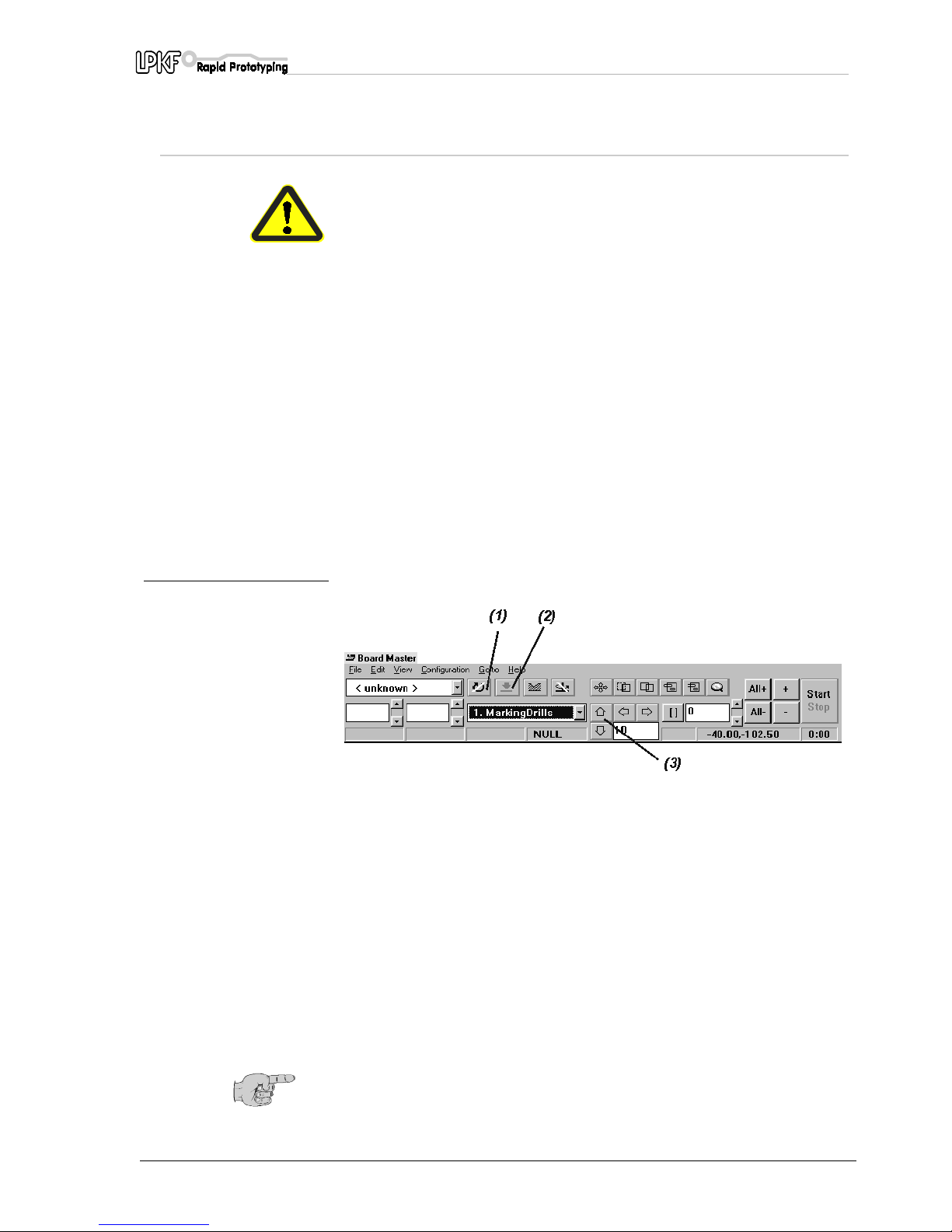
fig. 6:
1.
Move the head manually using the cursor keys on the
BoardMaster
toolbar (3).
2.
Switch on the motor. (1)
(The motor runs at low speed during the warm-up phase)
3.
Wait for the warm-up phase to complete.
4.
Lower/raise the head (2).
5.
Switch off the motor (1).
6.
Check the interface configuration, the connecting cable and the PC
interface if the equipment does not move.
Note: The motor cannot be switched off when the machine is in the
tool change position.
Page 22
Functional test with LPKF BoardMaster
22 ProtoMat C30/C30-S
7.1 HOME position and registration hole system
The HOME position must be on the machine's axis of symmetry
(registration hole system) for double-sided base.
Double-sided base material are rotated about this axis of symmetry.
Inaccuracies in the HOME position result in misalignment when doublesided base are rotated during the machining process.
The HOME position is contained on the configuration diskette supplied
as standard. With the
BoardMaster
program and configuration diskette
correctly installed, the HOME position corresponds to the setting for the
x/y coordinates as measured during the acceptance test.
Note: The registration hole system can only be guaranteed to be
parallel for the current position of the registration hole strips.
The front registration hole slide must be pushed against the pin in
the reference groove (reference point).
An additional hole must be drilled for each format in the rear
registration hole strip if base material of different sizes is used.
To do this, move from the HOME position towards the rear
registration hole strip.
Now move the rear registration hole strip to the required position.
An additional hole is drilled in the slide using a 2.95 mm drill.
The position of the slide for the various holes should recorded or
marked on the circuit-board plotter.
This guarantees parallelism for different formats.
You will need to perform a test run on the machine to check the
coordinates of the Home position on new machines and after
transporting the system.
The individual steps are described in the next section,
"Checking and
correcting the HOME position".
No further action is required if the preset coordinates are correct. If this
is not the case, the corrected coordinates will have to be entered in
BoardMaster
. See the section entitled
"Programming the HOME
position in
BoardMaster
".
7.2 Checking and correcting the HOME position
The test file Null-Pkt.LMD is supplied with installation program to simplify
the procedure for checking the HOME position.
This program drills a hole on one side of the board and then rotates the
board before milling a circle in the same place. This allows you to
perform a visual check on the position of the Home point in both axes.
Caution! Bevore beginning you must read the chapters " Operating
the working depth limiter" and "Changing a tool (C30)" as well as
"Changing a tool (C30/S).
Page 23
Functional test with LPKF BoardMaster
ProtoMat C30/C30-S 23
Carry out the following steps:
› Make registration holes in double-sided base material.
› Secure the material and drilling backing (2 mm) onto the base plate
using the registration hole pins. (see also the section entitled
"Securing the board onto the machine bed").
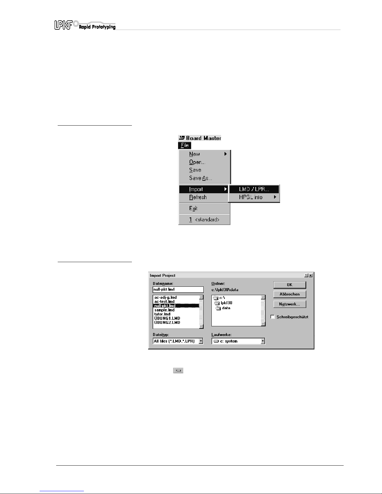
› Start up
BoardMaster
and select
LMD
or
LPR
from the
FILE,
IMPORT
menu.
fig. 7:
› Now select the file
NULL-PKT.LMD
and import it by clicking OK.
fig. 8:
› Click on to zoom the display and enclose the detail by clicking
and dragging with the left mouse button.
Page 24
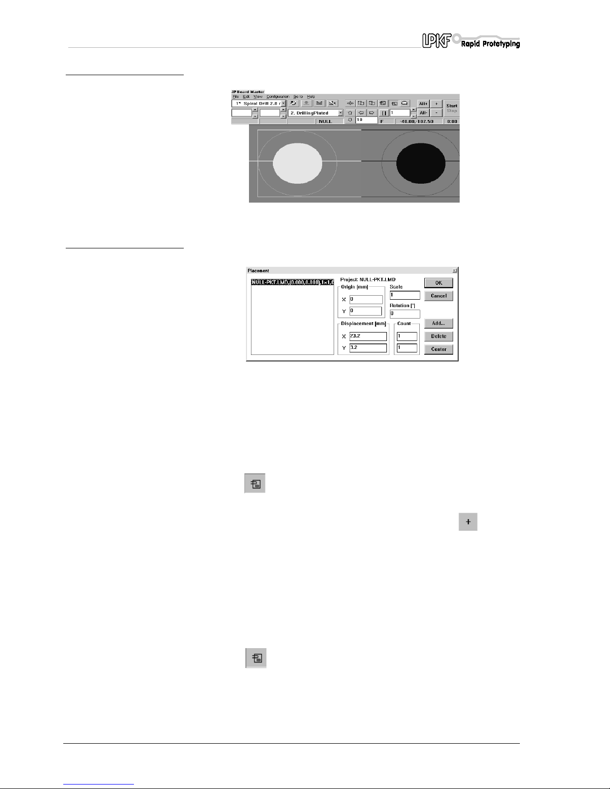
Functional test with LPKF BoardMaster
24 ProtoMat C30/C30-S
fig. 9:
› Right-click on the project.
fig. 10:
The PLACEMENT dialog box opens.
› Specify the position in the
Reference point
box as x=0, y=0 and
confirm by clicking on OK.
› Select the
DRILLINGPLATED
process from the production phase
list box.
› Click on and enclose the first hole by clicking and dragging with
the left mouse button.
› Now enable the selected hole for machining by clicking and
START
.
The software now prompts you to insert the specified drill. The hole is
drilled in the board once you have confirmed that the drill has been
inserted.
› Next move to the PAUSE position and rotate the board about the X
axis.
› Now select the
MILLINGTOP
process from the production phase list
box.
› Click on once again and enclose the milling track
corresponding to the first hole by clicking and dragging with the left
mouse button.
Page 25
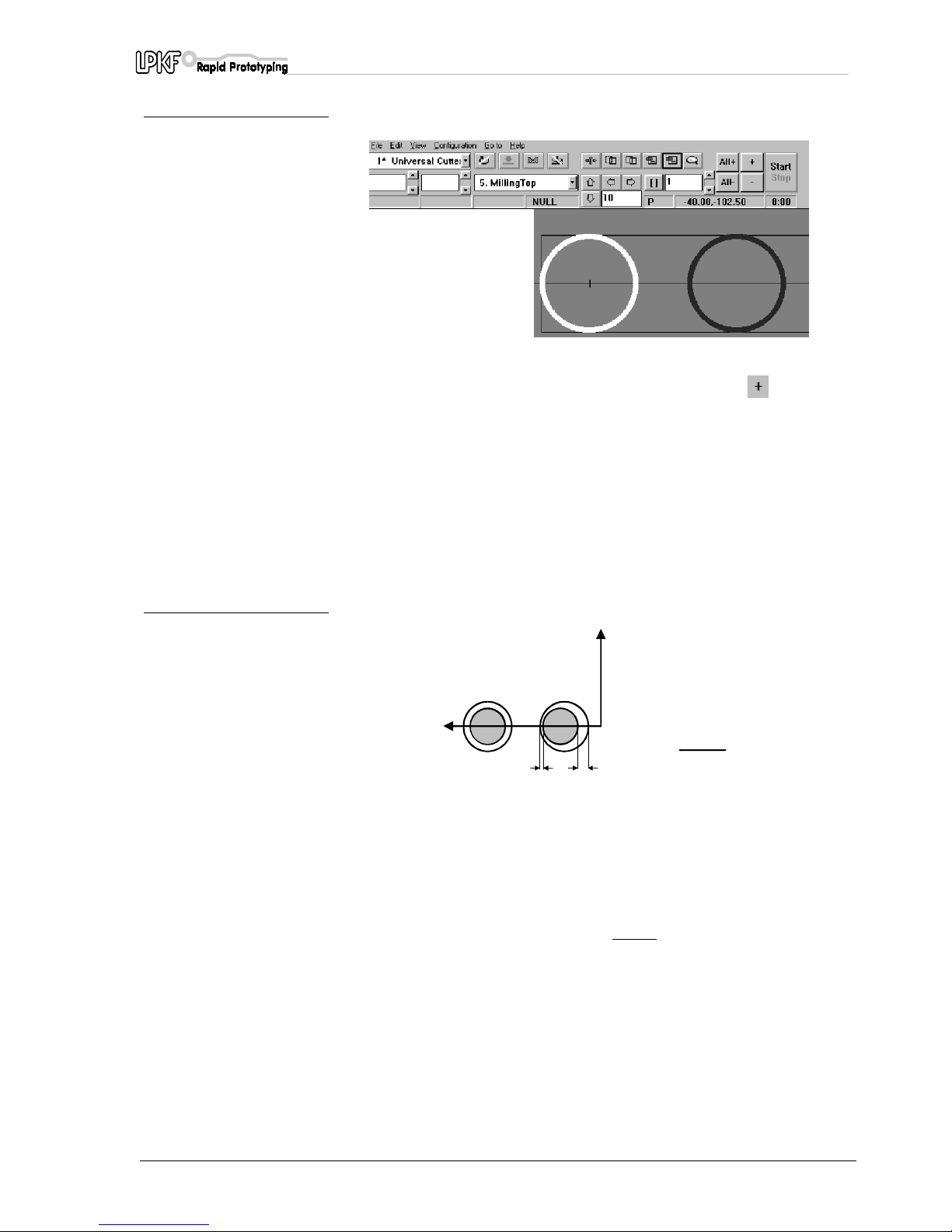
Functional test with LPKF BoardMaster
ProtoMat C30/C30-S 25
fig. 11:
› Now enable the milling track for machining by clicking and
START
.
The software again prompts you to insert the specified tool (see
chapter: changing a tool) and mills a circular track once you have
confirmed that the specified tool has been inserted.
› Check the settings, including the milling pass width and the milling
depth setting before you start machining.
Check visually that the milled channel passes precisely around the
centre point of the hole.
fig. 12:
› The Home position must be corrected if the milled line does not pass
exactly through the centre point.
This can be done directly by amending the Home position in the
MACHINE PARAMETERS
dialog box (see the section entitled
"Programming the Home position in LPKF BoardMaster"
).
The correct value can be calculated using the formula given above.
The Y coordinates must always be added
to the correction value.
› The procedure should be repeated as a check after making a
correction. It is advisable that you use the second hole and milling
track in the test program if the same board is to used to perform the
check.
› Take a note of the coordinates of the new Home position.
+Y
Korrekturwert:
(B-A)
4
B
A
+X
Page 26
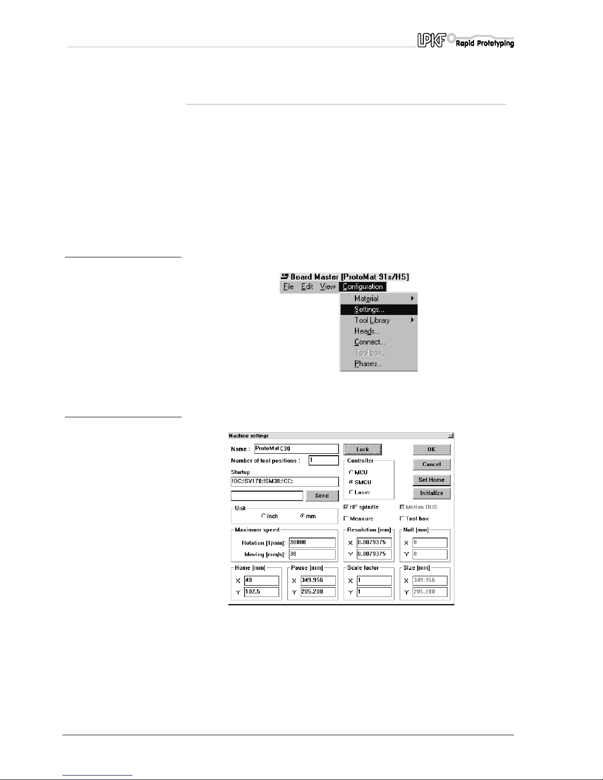
Functional test with LPKF BoardMaster
26 ProtoMat C30/C30-S
7.3 Programing the HOME position in
LPKF BoardMaster
As previously explained, the Home position of the LPKF
ProtoMat C30
(C30/S)
must lie precisely on the machine's axis of symmetry (the
registration hole system with the red plastic slides) when you are
machining double-sided base. You must enter a correction if a check as
described above shows that the Home position does not lie on the axis
of symmetry.
Proceed as follows to do this:
› Start up
BoardMaster
.
› Select
CONFIGURATION, SETTINGS
from the menu bar.
fig. 13:
› Click on
UNLOCK
so that you can make entries in this dialog box.
fig. 14:
› If necessary, correct the Home position coordinates by increased or
decreasing the value by the value previously measured.
› The new values will only be saved when the
MACHINE SETTINGS...
dialog box is closed and you quit
BoardMaster
.
Page 27
Functional test with LPKF BoardMaster
ProtoMat C30/C30-S 27
7.4 Creating a new registration hole system
The registration holes in the red registration hole strips grow with use
over time will no longer be as precise as they originally were.
New holes must be drilled in the strips if this is the case.
The registration hole strips must be replaced if there are too many holes
them after some time.
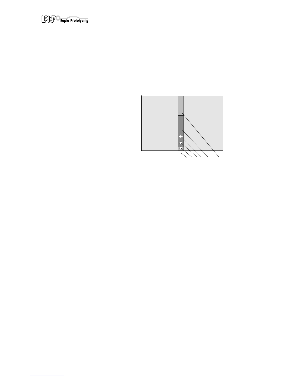
fig. 15: Front strip of the registration
hole system
A new registration hole system is created as follows:
› First press the two registration hole strips into the machine groove,
with the front registration hole strip pushed against the reference pin
at the front of the groove.
The distance between the two registration hole strips should be
approximately the size of the base material in the X axis.
› Select the tool in
BoardMaster
: "Spiral Drill Ref 2.95 mm"
› Fit the 2.95 mm diameter drill so that the distance between the base
plate and the tip of the drill is approximately 0.5 mm.
This is the
only
time a tool is not inserted into the collet as far as it
will go.
› Adjust the working depth limiter to the very top using the knurled
screw so that the drill stroke is lengthened.
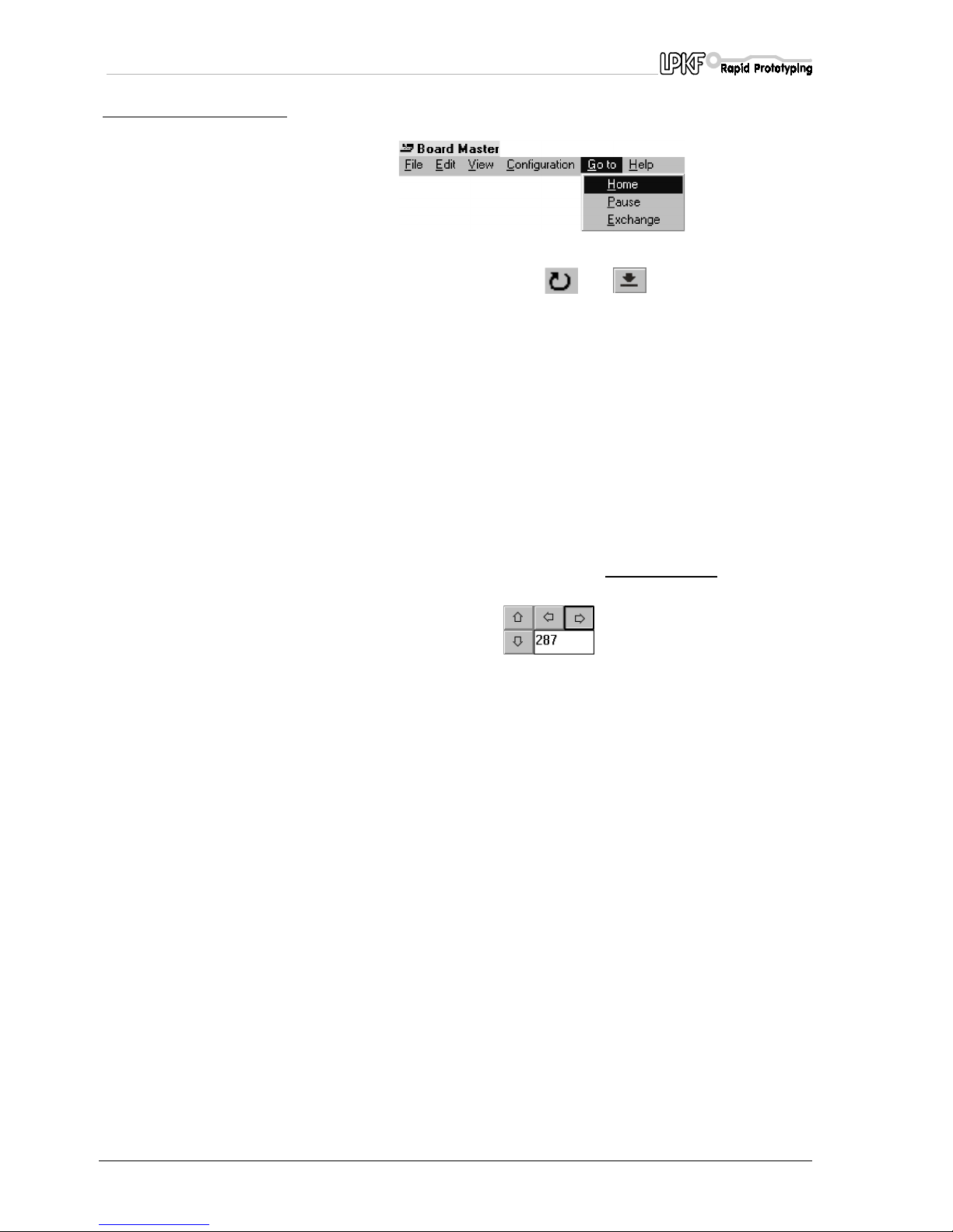
› Use
GO TO, HOME
from the
BoardMaster
menu to move the plotter
head to the Home position and then use the arrow buttons to move
the head to approximately the centre of the front registration hole
strip.
1- reference pin, may be covered by two-pin stripe (5) 4- mirror axis
2- front alignment pin 5- two-pin stripe
3- HOME position, min 10 mm distance to the
alignment pin
6- two-pin groove
1234 5 6
Page 28
Functional test with LPKF BoardMaster
28 ProtoMat C30/C30-S
fig. 16:
› Switch on the motor by clicking and (raise/lower head) to
drill a hole approximately 4 mm deep.
Do not move the position of the plotter head in the Y axis again.
› Use the arrow buttons in
BoardMaster
to move the plotter head
approximately 25 mm in the positive X direction and define this
position as the new Home position:
Open the
MACHINE SETTINGS...
dialog box in
BoardMaster
via
CONFIGURATION, SETTINGS
, select
UNLOCK
and click on the
SET HOME
button. (see also the section entitled Programming the
HOME position in LPKF
BoardMaster
)
› Move along the X axis to the second, rear registration hole strip and
drill a hole approximately 4 mm deep there too. It is imperative that
you do not move in the Y direction. Select a distance suitable for
working with a standard base material. For example, an A4 board is
297 mm, so a registration hole 5 mm from the edge of board gives a
distance between the holes of 287 mm. Simple method:
› Enter the value 287 in the
STEP WIDTH
box in
BoardMaster
and
then press the arrow button.
The plotter head moves in one 287 mm step to the new position.
› Now remove the drilling tool by selecting a different tool in
BoardMaster
.
› Move the plotter head to the side. Insert two alignment pins in the
holes now made in the registration hole strip.
Please check that the pins are positioned securely as any play has a
detrimental effect on alignment accuracy.
› Mark old holes with a felt pen so they cannot be confused with the
new ones.
› Position the previously drilled base material and drilling backing over
the alignment pins.
The format of the base material should be selected so that the
registration hole strip does not need to be moved more than 10 mm.
Moving the registration hole strip more than 10 mm reduces the
accuracy of the registration hole system.
Page 29

Functional test with LPKF BoardMaster
ProtoMat C30/C30-S 29
› Now secure the base material in this position with adhesive tape
(we recommend Tesakrepp 5250) on all four sides.
Danger! Please note that very sharp tools are involved and that
they may become hot. Always work with the vacuum system
switched on to avoid injury from swarf..
Note: You should select a distance between the registration holes
which allows you to work with standard base material.
A DIN A4 size board has a side length of 297 mm so holes 5 mm
from the edge give a distance between the holes of 287 mm.
Page 30
Tutorial on creating a printed circuit board
30 ProtoMat C30/C30-S
8.0 Tutorial on creating a printed circuit board
It is assumed that the relevant milling data has already been loaded or
prepared in
BoardMaster
. The data from the
CircuitCAM
tutorial can be
used, for example.
A further requirement is that the Home position has been programmed
exactly as described above.
Caution! Take care when handling the tools. Danger of cutting. Do
not forget to switch on the vacuum system during machining.
Bevore beginning you must read the chapters " Operating the
working depth limiter" and "Changing a tool (C30)" as well as
"Changing a tool (C30/S).
› Move to the Pause position using the
BoardMaster
menu
GO TO,
PAUSE.
› Secure the base material with alignment pins as described in the
section entitled "Securing the board".
› Move to the bottom left corner (-x, -y) of the base material using the
traverse buttons in
BoardMaster
such that the working depth limiter
does not quite come into contact with the adhesive tape.
Program this corner in the
BoardMaster
menu
CONFIGURATION,
MATERIAL, SET X,Y-MIN
.
› In the same way, move to the top right corner (+x, +y) of the material
and program this under
CONFIGURATION, MATERIAL, SET X,Y
MAX.
The material is shown in
BoardMaster
as light grey on the dark grey
machine surface.
› Select
LMD OR LPR
under
FILE, IMPORT
and import the tutorial file
TUTOR.LMD.
(See also the instructions for importing the file null-pkt.lmd in the
section entitled "Checking and correcting the HOME position")
› Position the view of the board in
BoardMaster
using
EDIT,
PLACEMENT
such that all graphical data is located on the material.
Note: You can open the PLACEMENT dialog box by right-clicking
when the mouse pointer is positioned immediately over the
graphical data.
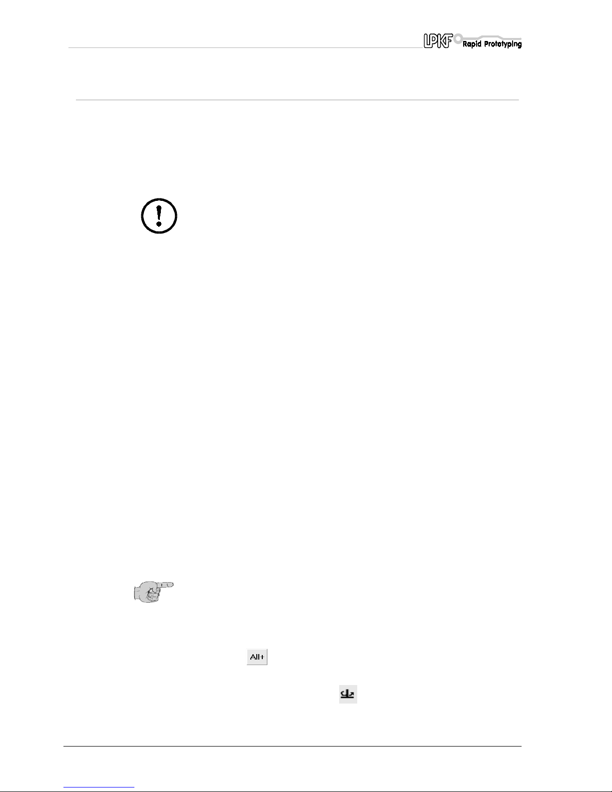
› Select the first machining phase,
DRILLINGPLATED
.
› Click on to select the drilling data. Selected data is shown
lighter.
› Click on
AUTO-MOTOR-ON
. (Right motor button in
BoardMaster
).
› Click on
START
.
Page 31
Tutorial on creating a printed circuit board
ProtoMat C30/C30-S 31
BoardMaster requests the tool required for the machining phase and
the machine moves to the TOOL CHANGE position and automatically
switches the motor off.
› Push down the lever to open the collet and lock it in position by
moving it to the right.
The tool in the machine can now be removed from the collet using the
tweezers supplied.
› Insert the tool requested as far as it will go and unlock the lever by
moving it to the left and then up.
The collet is now closed.
› Confirm the tool change by clicking OK.
The motor switches on and the first drilling diameter of the drilling
phase is executed. Once the holes of the current diameter have been
made, the next tool is requested and changed in the same way.
› Once the drilling phase has finished, the
MILLINGBOTTOM
milling
phase is selected once any galvanic through-hole plating has been
carried out.
› Click on to select the milling data.
The selected data is shown lighter.
› Click on the button
START
.
The plotter head moves to the TOOL CHANGE position and prompts
for the current tool.
› Click
STOP FOR ALTERATION AFTER TOOL CHANGE
in the
TOOL
combo box to set the milling depth.
› Insert the universal milling cutter.
› Click OK to quit the dialog box.
› Use the arrow buttons in
BoardMaster
to move to a free position on
the base material.
› Set the step size to 5-10 mm in the
STEP SIZE
box.
› Click the
AUTO-MOTOR-ON
button,
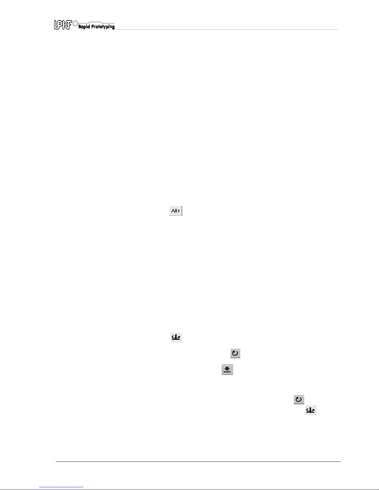
› Switch on the motor using the
MOTOR ON/OFF
button,
› Lower the head by clicking and move the head using the arrow
buttons. Set the milling depth. See also the section entitled "How the
mechanical working depth limiter works".
› Switch off the motor by clicking on
MOTOR ON/OFF
and switch
the motor back on by clicking on the
AUTO-MOTOR-ON
button.
› To start the machining use the
START
button.
› Then move to the Pause position and turn the material if you are
machining a double-sided base.
Page 32
Tutorial on creating a printed circuit board
32 ProtoMat C30/C30-S
› Select the
MILLINGTOP
milling phase and machine as described
above. If required, select the
CUTTING
milling phase and machine
with a contour milling cutter.
› Move to the Pause position, remove the board and proceed as
described in the section entitled "Cleaning the board".
8.1 Reprogramming the machine data
You will have to re-enter the Pause or Home position data in the
machine settings if the PC operating system crashes and the head no
longer moves to these positions. Proceed as follows:
› Start up
BoardMaster
.
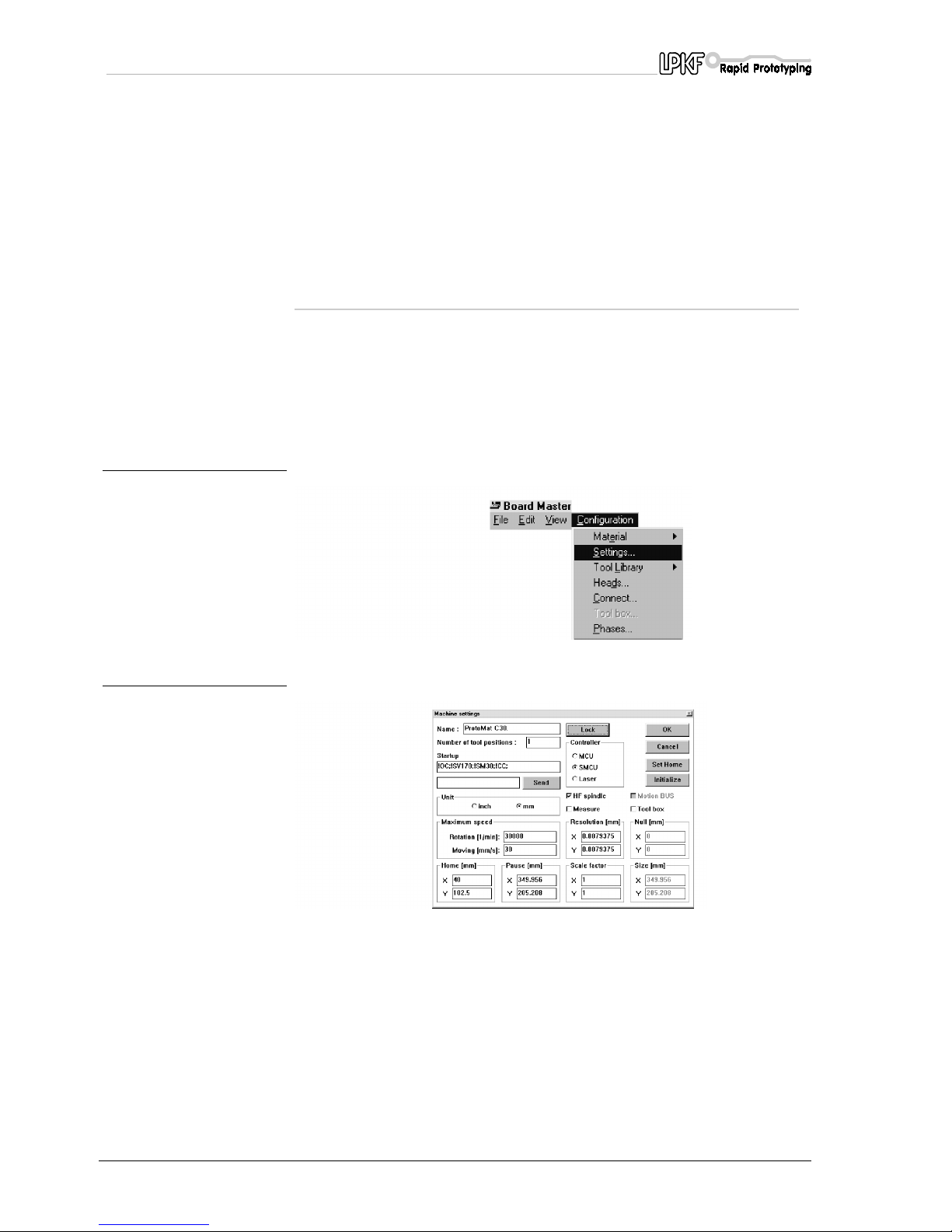
› Select
CONFIGURATION, PARAMETERS
from the menu bar.
fig. 17:
fig. 18:
› Click
UNLOCK.
This activates the CONTROL, SET HOME and INITIALIZE boxes.
› Click on
INITIALIZE
.
The device moves to all four end positions. The device then comes to
a halt in the zero position (at the front right). The traverse range thus
determined is displayed under SIZE and saved by BoardMaster.
See the BoardMaster Manual for more detailed information.The
coordinates for the Home position are generated automatically.
The X value is set at 0 and the Y value corresponds to half the value
specified for Y under
Size
.
Page 33

Tutorial on creating a printed circuit board
ProtoMat C30/C30-S 33
Now enter the values noted down for the Home position in the Home
box. These values are determined as described in the section entitled
"Checking and correcting the Home position".The coordinates for the
Pause position correspond to the values in the
Size
box. You can
enter any coordinates here.
› Click OK to quit this box.
›
BoardMaster
must be shut down and restarted.
The new values are saved when the
MACHINE SETTINGS...
dialog box
is closed and you quit
BoardMaster
.
Page 34
Tools, material and accessories
34 ProtoMat C30/C30-S
9.0 Tools, material and accessories
9.1 Tools
The tools for the
LPKF ProtoMat C30 (C30/S)
come in two different
lengths.
Tools used to machine the material surface (milling and engraving) are
36 mm long while tools used for drilling or contour milling are 38 mm
long. The following tools are available:
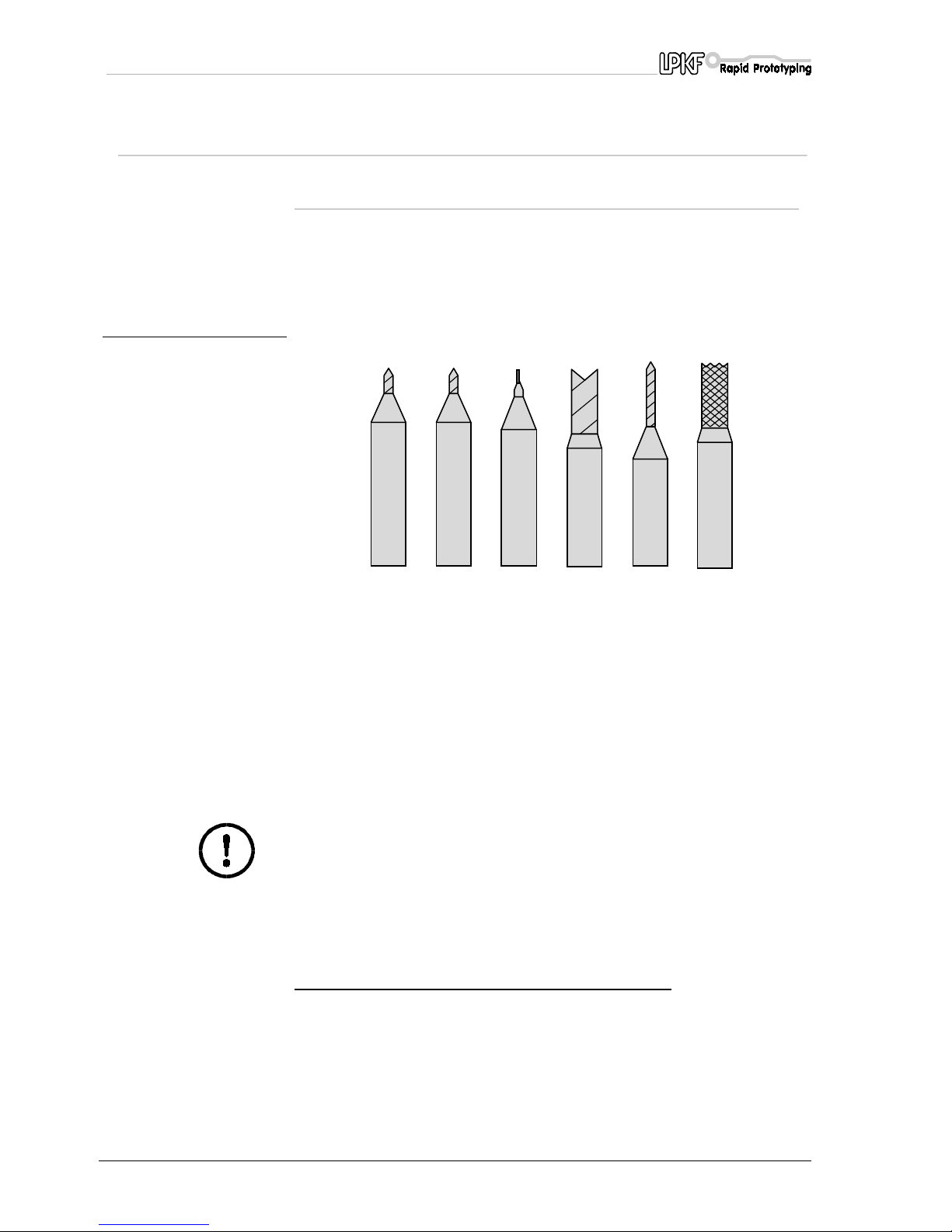
fig. 19: LPKF tools for circuit-board
plotter
Caution! Only change tools in the positions defined for this
purpose.
The tools must always be inserted in the toolholder as far as the stop,
otherwise the working depth will be incorrect.
In certain circumstances, this can even result in damage to the machine
base plate.
Tweezers are supplied for tool insertion and removal.
1
- universal LPKF milling
cutter and drill
for milling isolation channels and for engraving front panels
from 0.2 - 0.5 mm (depending on depth set). 36 mm long
2
- LPKF microm illing cutter for milling 0.1 to 0.2 mm isolation channels (depending on
depth set) with a 17 µm copper cladding on the base
material. 36 mm long
3
- LPKF HF milling cutter for creating 0.25 mm or 0.4 mm wide
rectangular section isolation channels.
4-
double-chamfered cutter
(0.8 mm; 1 mm; 2 mm)
for engraving front panels and for engraving wider isolation
channels. 36 mm long
5
- twist drill of various diameters for drilling in base material. 38 mm long
6
- contour milling cutter
(1.0 mm; 2.0 mm)
for milling out cut-outs in the base material. 38 mm long
Page 35

Tools, material and accessories
ProtoMat C30/C30-S 35
9.2 Materials used for machining
In general, all base materials supplied by LPKF can be used for
machining. You are free to machine all other materials at your own risk.
Please follow the manufacturers' instructions.
However, phenol resins of lesser quality, such as FR 2, can adversely
affect the milling quality.
Glass fibre reinforced epoxy material (FR 4 or G 10) can present a
health hazard due to the milling dust produced (allergies, risk of cancer).
Tool service life is also substantially reduced.
Caution! Never work without the extractor running.
We recommend epoxy material without glass fibre (FR 3). A total
thickness of 1.5 mm with a 35 µm copper coating is normally used.
Yielding milling is of the highest quality and a high tool service life, FR 4
has no known drawbacks other than a slightly reduced mechanical load
capacity (breakage). This should not be a significant drawback for
prototype boards unless particularly heavy components are to be
mounted.
Even finer milling channels can be engraved on 17 µm material at a
higher packing density. A 5 - 17 µm copper thickness is used for
galvanically through-hole plated, double-sided base to prevent an
excessively thick copper layer building up following galvanic copperplating.
Compromises must be taken for 70 µm material when setting the milling
depth in that a deeper milling depth results in wider milling passes of 0.3
to 0.6 mm. Special base materials with a thicker copper layer of up to
300 µm can no longer be machined with the LPKF universal milling
cutter. Contour milling cutters or special tools are needed for these
materials. In these cases, we would ask that you consult us and send
sample material so that we can carry out any tests which may be
necessary.
A drilling backing is essential for all machining processes on base
material. This allows holes to be drilled through the board without
damaging the machine. The drilling backing can be made simply of
bakelized paper and should be 2 mm thick.
Material supplied by LPKF and suitable for machining:
FR3 material: engraving, drilling, milling
FR4 material : engraving, drilling, milling
Engraving film: engraving
Other materials upon request.
Page 36

Tools, material and accessories
36 ProtoMat C30/C30-S
Danger! Do not allow to the material overheat - lethal gases may be
produced.Carcinogenic dusts may be produced when working with
materials containing glass fibres. You should therefore always
work with the vacuum system switched on. Carcinogenic dusts or
hazardous gases may be produced when working with unknown
materials. Ask your supplier or the manufacturer before you begin
machining.
Page 37
Procedures for milling and drilling
ProtoMat C30/C30-S 37
10.0 Procedures for milling and drilling
10.1 Securing the board
Make 3,0 mm or 3,05 mm diameter congruent registration holes in the
base material and drilling backing in the X axis.
This can also be done with any bench drill. Note that the diameter
decreases during galvanic through-hole plating.
Note: The drilling backing should be drilled to a larger diameter,
such as 5 mm to allow for inaccuracies in the registration holes.
› Move the plotter head to the Pause position.
› Insert alignment pins in the front and rear registration hole strips.
It is essential that you make sure the front registration hole strip in
the machine groove is pushed against the reference pin at the front.
› Position the drilled base material and drilling backing over the
alignment pins. The format of the base material should be selected
so that the registration hole strip does not need to be moved more
than 10 mm. Moving the registration hole strip more than 10 mm
reduces the accuracy of the registration hole system.
› Now additionally secure the base material in this position on all four
sides with adhesive tape (we recommend Tesakrepp 5250).
This prevent the corners of the board bending up.
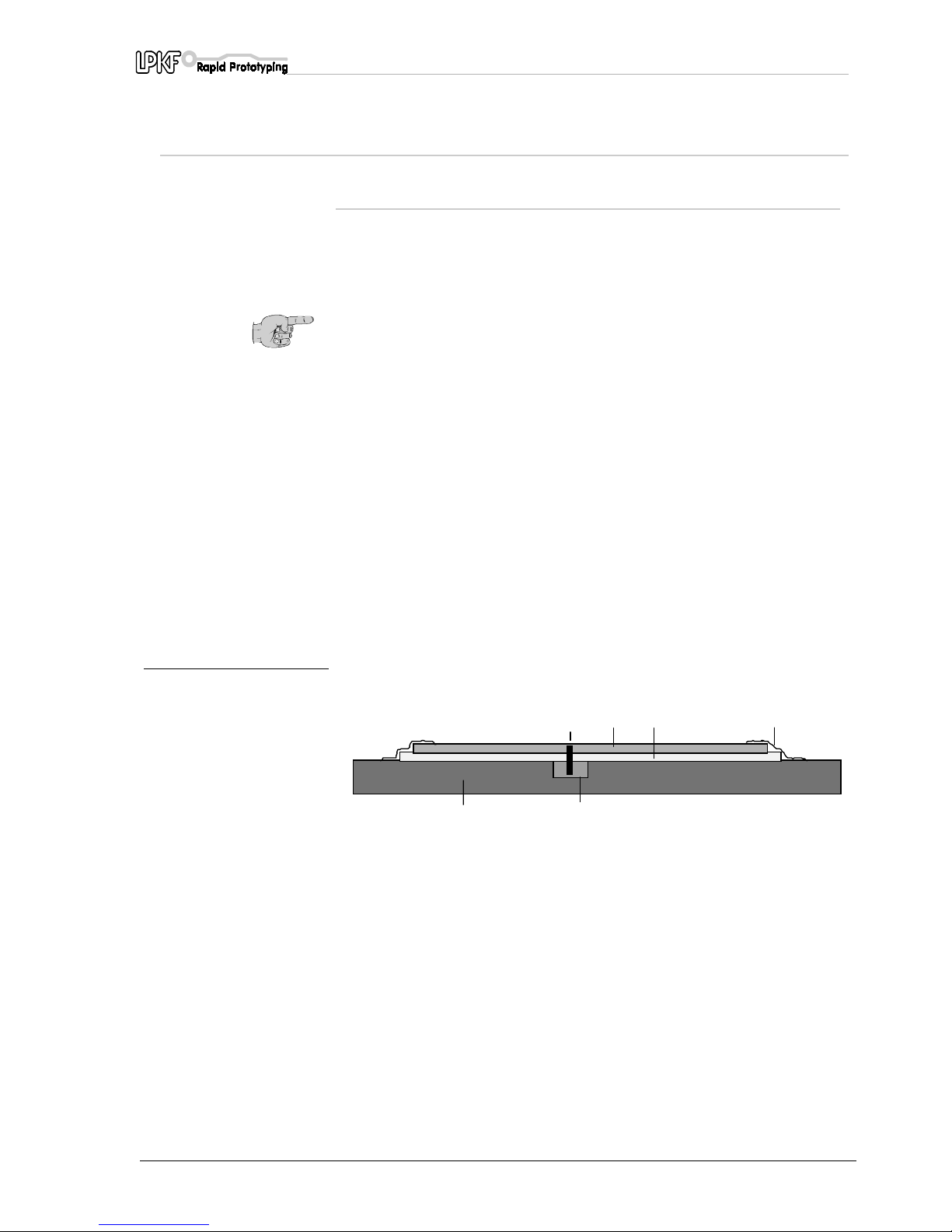
fig. 20: Securing the board
The alignment pins hold the board in position. They also act as a
reference when double-sided base are rotated.
This is particularly important for contour milling.
It is important that no adhesive tape, drilling or milling swarf is left
between the individual layers to ensure that the base material lies
absolutely flat. Small particles under the base material have an adverse
affect on the uniformity of the milling depth.
1
- Machine bed (aluminium base plate)
4
- 2 mm thick drilling backing
2
- 3 mm diameter alignment pins
5
- Adhesive tape
3
- Base material approximately 1.6 mm thick6- Registration hole strip
1
2
3
4
5
6
Page 38
Procedures for milling and drilling
38 ProtoMat C30/C30-S
Caution! Switch on the vacuum system. Bear in mind that the
vacuum filter might need be changed.
10.2 Operating the working depth limiter
Danger! Keep your fingers clear of the machine's traverse range
during operation.
It is particularly important that you keep the milling depth constant when
milling isolation channels in base materials which tend to be slightly
curved. LPKF
ProtoMat C30 (C30/S)
achieves this using the mechanical
working depth limiter.
This has following benefits:
• The depth limiter rides on the surface of the material. The
working depth limitercan follow slightly warped boards.
• The material is held down within certain limits by the working
depth limiter. The head is lowered by a solenoid actuator and
raised by a spring.
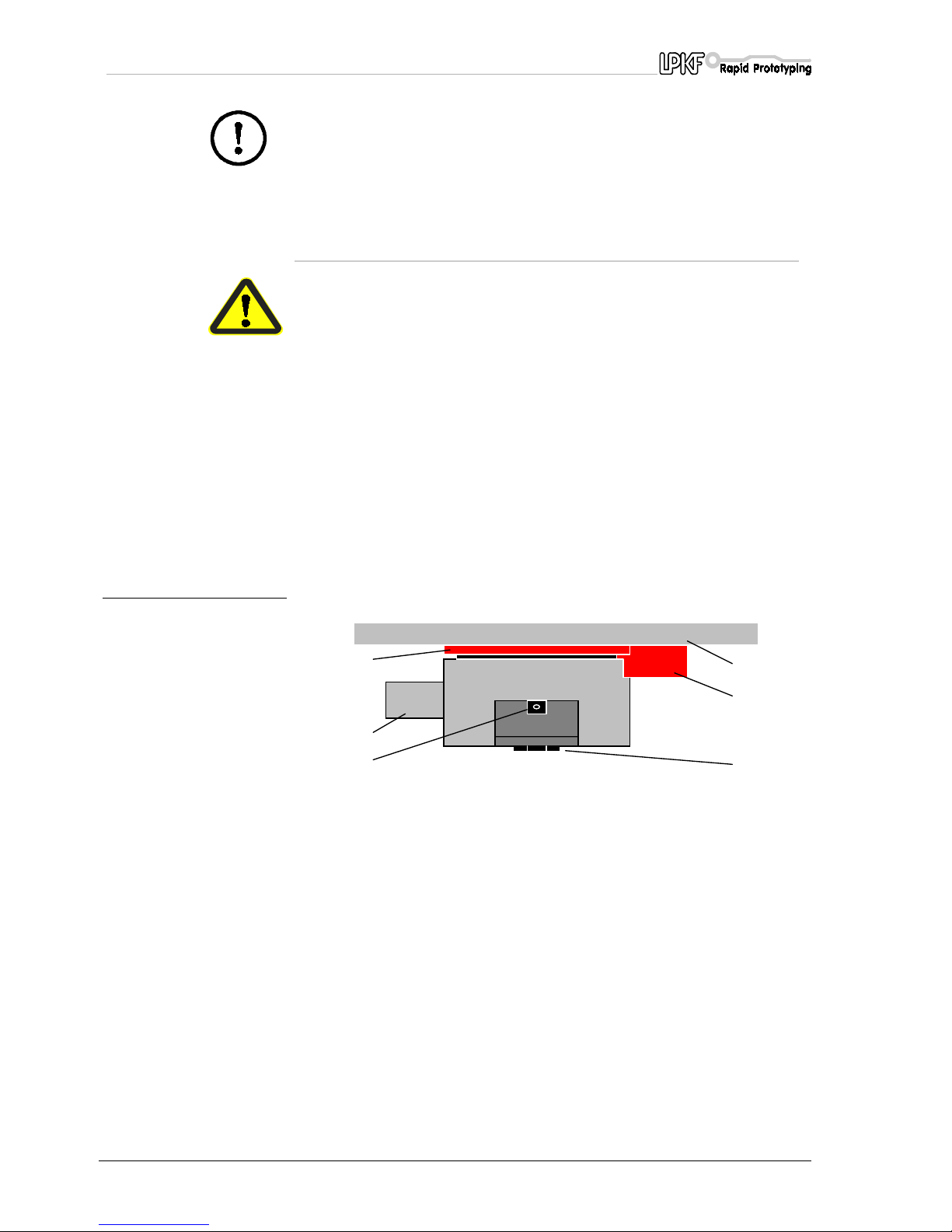
fig. 21: The LPKF ProtoMat C30
(C30/S) working depth
limiter
The milling depth is set by adjusting the knurled nut (2) on the working
depth limiter. Turning the wheel clockwise increases the milling depth
and also the milling width in the case of LPKF universal milling cutters
due to their conical shape.
Turning the wheel anti-clockwise reduces the milling depth.
The milling depth is altered by approximately 4 µm for each click of the
wheel. Turning the wheel anti-clockwise is easier than turning it
clockwise, particularly when the head is lowered.
1
- Holding plate
4
- Suction connector
2
- Knurled nut used to set milling depth
5
- Tool fixing screw (only ProtoMat C30)
3
- Holding block for working depth limiter
6
- Feeler ring in the working depth limiter
1
2
3
4
5
6
Page 39
Procedures for milling and drilling
ProtoMat C30/C30-S 39
10.3 Changing a tool (C30)
› Remove the tool fixing screw (see picture working depth limiter)
› Pull out a possibly available tool with the help of a tweezers from the
tool housing.
› Introduce the new tool up to the plot in the tool housing with a
tweezers.
› Move and fix the fixing screw.
10.4 Changing a tool (C30/S)
The plotter spindle collet on the
ProtoMat C30 (C30/S)
is operated by a
lever which simultaneously disengages the DC motor via a clutch as a
spring packet opens the collet.
Caution! There must be a tool in the plotter spindle collet whenever
the machine is switched on. It is imperative that the collet is closed.
(The collet is closed when the lever is in the “up” position).
Operating the lever when the motor is running could damage the
coupling between the motor and the collet. Do not switch on the
motor by opened tool clamp or without tool!
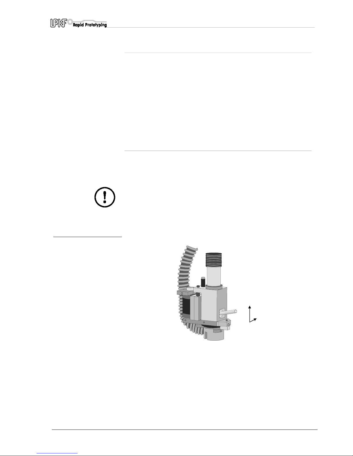
fig. 22: Operating the plotter spindle
collet
Position A: Lever in the normal position. The collet is closed.
The motor is connected to the spindle by a clutch.
Position B: The lever must be pushed down to open the collet.
The clutch disengages the motor and a spring pack opens
the collet.
Position C: After the lever is pushed down, the open collet is locked
open by moving the lever to the right. It is now a simple
matter to change the tool using the tweezers supplied.
A
B
C
Page 40
Procedures for milling and drilling
40 ProtoMat C30/C30-S
10.5 Drilling
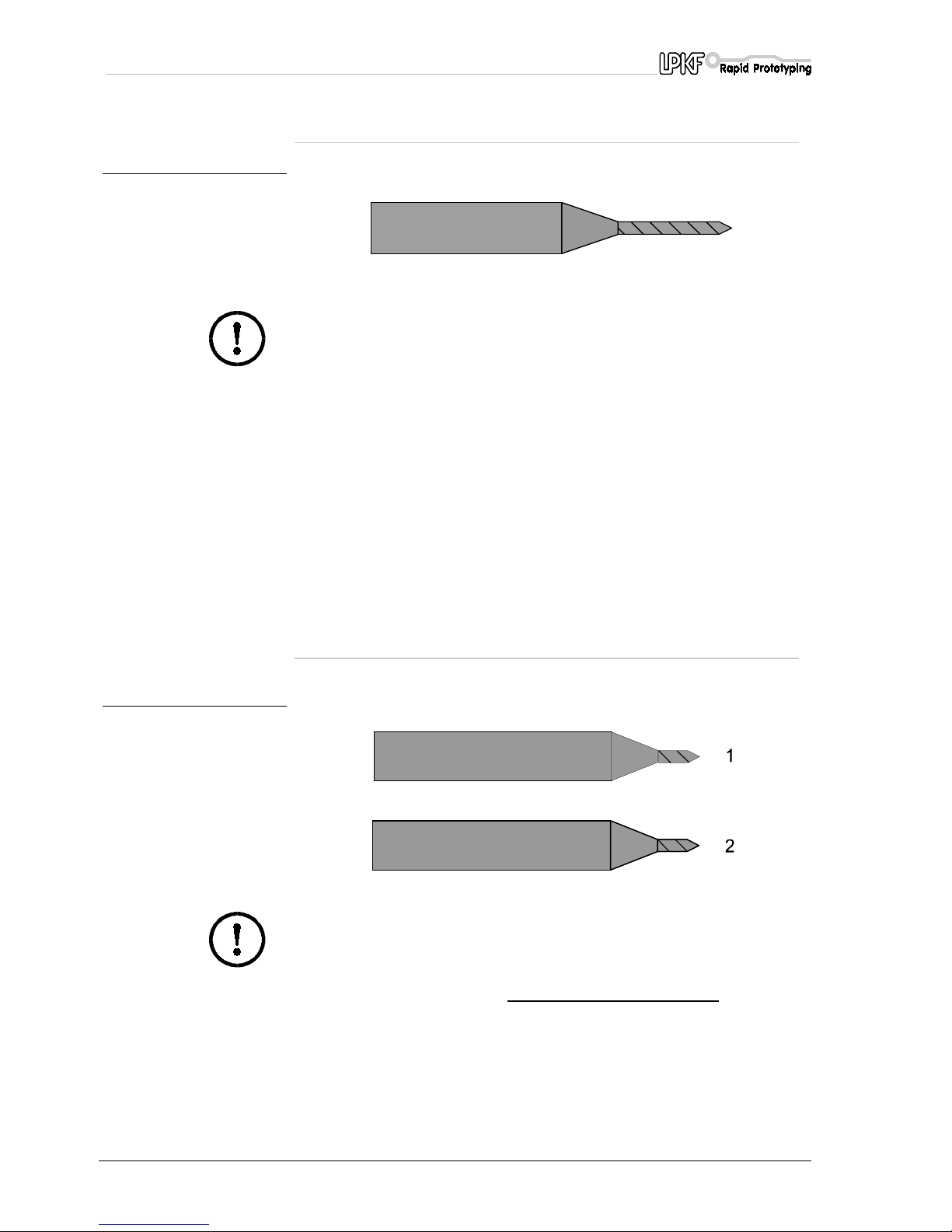
fig. 23: Twist drill
Caution! Make sure that the board is secured in position before
drilling. Switch on the vacuum system.
The boards must be drilled with drills designed specifically for boards. It
is important that the head always lowers at a constant speed. This is
ensured by a damper built into the plotter head.
Lowering the head too quickly may result in burring, particularly with
holes of small diameter. We therefore recommend that you punch holes
with a small diameter before drilling. The
MARKINGDRILLS
phase in
BoardMaster
is intended for this purpose and uses a special universal
milling cutter, the
0.2 MM UNIVERSAL MARKING CUTTER
.
Only one board can be drilled at a time. It is not possible to stack boards
one on top of the other. A drill cover plate is not required.
All drills are 38 mm long.
See the section entitled “Practical tips” for further instructions.
10.6 Isolation milling
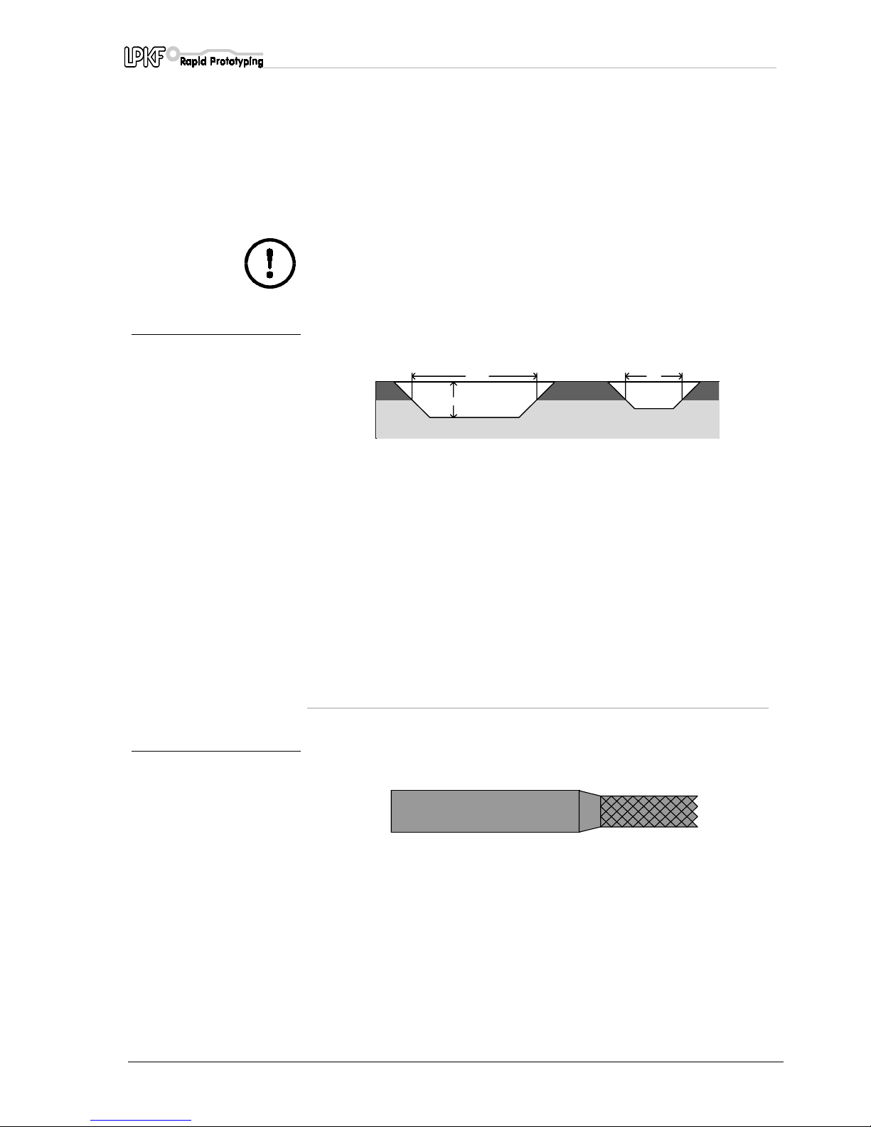
fig. 24: LPKF Universal (1) and
microcutters (2)
Caution! Make sure that the board is positioned securely before
milling. Switch on the vacuum system.
Ensure that the (36 mm long)
LPKF universal milling cutters
being used
are
sufficiently sharp
before you start milling. The milling width is
preset in
CircuitCAM
by selecting the isolation track width and the
appropriate tool. The preferred milling width is between 0.2 and 0.4 mm.
Page 41
Procedures for milling and drilling
ProtoMat C30/C30-S 41
As a rule, the milling depth must be set as wide (deep) as possible. The
tool wears more quickly if only the extreme milling cutter tip (<0.2 mm
isolation) is used than with deeper milling.The LPKF micromilling cutters
can be used to create even finer isolation channels but their service life
will be only approximately 20% of that of the LPKF universal milling
cutters mentioned above.
Caution! Do not confuse micromilling cutters and universal milling
cutters. It is only possible to distinguish the two under a
microscope.
fig. 25: Milling passes using the
LPKF universal, and micro
cutters
See the section entitled “Practical tips” for more information.
The board must be cleaned after machining. This can be done either in a
brush machine or, alternatively, with a manual board cleaner (LPKF
accessories).
In either case, the board must be rinsed thoroughly with water to remove
any copper dust produced by brushing. After rinsing, the board must be
dried thoroughly (hair drier) and then protected against oxidation by a
soldering varnish.
10.7 Contour milling in base material
fig. 26: Contour milling cutters
The traverse speed has to be reduced for contour milling. This may differ
from material to material. Use only contour milling cutters (38 mm long)
designed specifically for this purpose: 1 or 2 mm diameter if possible.
The 1 mm contour milling cutter should only be used for internal cut-outs
(smaller internal radius). It breaks relatively easily so set the feed rate to
the minimum setting.
The 2 mm contour milling cutter is far more robust and is to be
recommended for milling external contours.
ca. 0.2mm
ca. 0.075mm
Cu
ca. 0.1mm
FR4
Page 42
Procedures for milling and drilling
42 ProtoMat C30/C30-S
Danger! All speeds and feed rates prescribed in
BoardMaster
are
for FR4 material. You should begin at a lower feed rate when
working with other materials. Please note that some materials,
including FR4, may produce carcinogenic dusts (from glass fibres).
You should therefore always work with the vacuum system
switched on. Always use a microfilter. Some materials (such as
Teflon) may produce lethal gases during cutting.
10.8 Milling wide isolation channels and rubouts
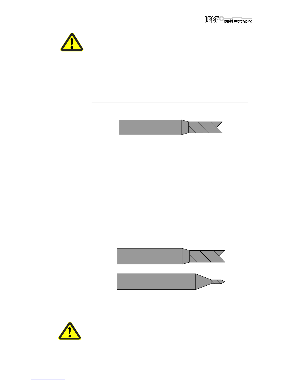
fig. 27: Double-chamfered cutter
Wide isolation channels and rubout areas (the removal of areas of
residual copper) can be created using 36 mm long double-chamfered
cutters.
Various diameters (0.8 mm, 1 mm, 2 mm, 3 mm) are available
depending on the size of the area of copper residue to be removed.
The milling depth must be set such that the copper is removed with
minimal burring. The 3 mm double-chamfered cutter is particularly well
suited to milling very wide isolation channels (VDE regulations).
10.9 Front plate engraving
fig. 28: Top: Double-chamfered
cutter. Bottom: LPKF
universal milling cutter
Set the traverse speed as appropriate for the engraving depth and the
material when engraving. Use an LPKF universal milling cutter or LPKF
double chamfered cutter.
Danger! Switch on the vacuum system, even when engraving.
Page 43

Procedures for milling and drilling
ProtoMat C30/C30-S 43
10.10 Milling solder-stop sheets
Create the pads in solder-stop sheets using a Unimill 100 Micromill with
a tool diameter of 0.15 mm.
The speed should be set to 20,000 rpm and the advance to 5 mm/s.
Note: Set the milling depth using an edge area of the solder-stop
sheet which is not used. Use the arrow buttons in BoardMaster to
mill a 2 x 2 mm square with the motor switched on and check the
depth.
› Once the milling depth has been set, start the milling procedure
using the file prepared by
CircuitCAM
.
› At the end of the milling procedure, check that all the pads have
been cut out.
› Start the milling procedure a second time if this is not the case.
10.11 Milling layout films
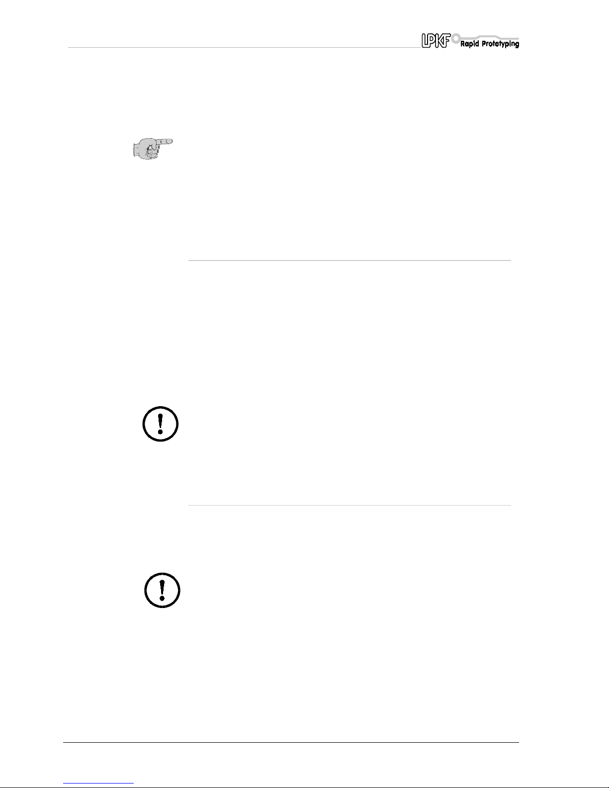
fig. 29: LPKF HF milling cutter
Layout filmscan be machined with LPKF HF milling cutters.
› Secure the film base (plexiglas or glass sheet) onto the machine
bench with Tesa tape.
› Lay the film material on the base with the coated (matte) side facing
upwards.
› Now flatten the film material out firmly flat and on the film support,
expelling any air completely.
› Now stick down the film on all four sides with a non-stretching
Page 44
Procedures for milling and drilling
44 ProtoMat C30/C30-S
› The film milling program may now be started.
Film material comes in DIN A3 and A4 formats (special sizes available
upon request).
Note: The film coating is easily scratched and is water soluble, so
do not let it come into contact with water.
The film can be recopied with a staining device upon request.
See the section entitled "Practical tips" for more information.
10.11.1 Staining milled films
Duroscal black stain is available for milled negative films which can then
be used to make positives.
The fully milled engraving film is stained with Duroscal stain by pouring
the liquid onto a SAFIR pad and spreading it evenly over the whole film.
Excess stain must be wiped off with cellulose wadding.
The stained film must be held against the light to check it and to find
poorly covered areas so that they can be re-stained.
Now remove the coating immediately. The stain must not be allowed to
dry.
Caution! Follow the instructions on the stain container. The stain
must not get onto the back of the film as it cannot be removed. The
stain is also very difficult to remove from other surfaces (fabrics,
skin). Wear an overall and rubber gloves.
10.11.2 Removing the coating
Treat only one film per container when removing coatings to prevent any
damage to the second film resulting from contact between its reverse
and a surface which is wet from the stain.
Caution! Follow the safety instructions on the quick-acting coating
remover container.
Page 45

Procedures for milling and drilling
ProtoMat C30/C30-S 45
There are two methods of removing the coating:
Quick coating removal.
Pour the quick-acting coating remover onto the film and immediately
wipe the dissolved protective coating with cellulose applying light
pressure. Now dry the film with cellulose wadding, blotting paper or a
cloth.
Removal with water.
This method involves placing the film in a bowl of hand-hot water (to
which a small amount of washing-up liquid has been added).
The protective layer dissolves after about 30 minutes.
Any remaining coating must be removed with a fine hand brush.
This method is more economical and kinder to the environment than the
quick-acting method of removal.
The film can be left in the water bath as long as you want.
Page 46
Tool libraries in BoardMaster
46 ProtoMat C30/C30-S
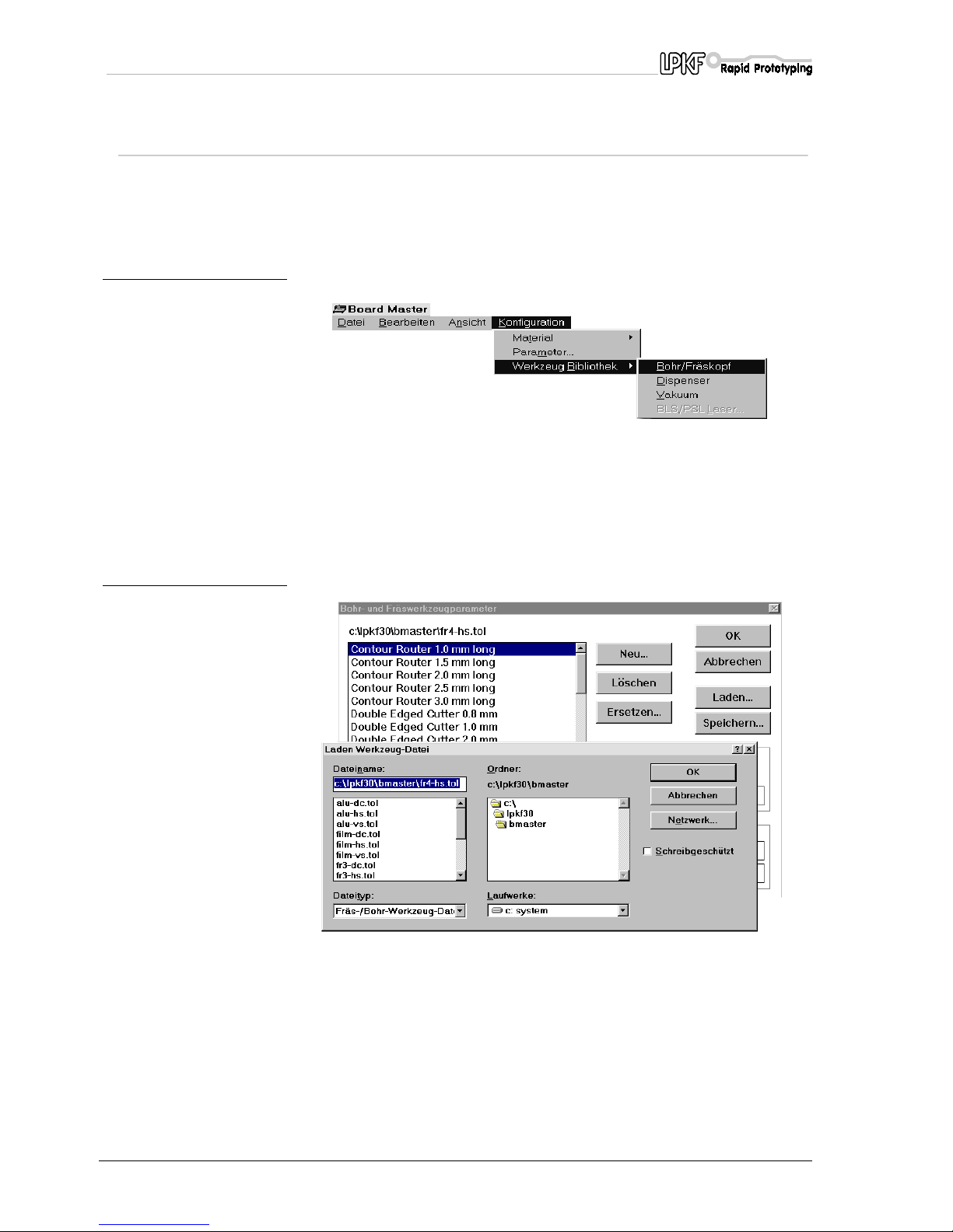
11.0 Tool libraries in
BoardMaster
BoardMaster
can be loaded with a previously created library of various
tools as an aid to deciding which tool can be used for which materials.
Select the Plotter head submenu of the Configuration,
TOOL LIBRARY
menu in
BoardMaster
.
fig. 30:
The
DRILLING AND MILLING TOOL PARAMETERS
dialog box opens
and you can now
LOAD
a suitable tool library from the directory
selected.
The tool library directory is called
C:\LPKF30\BMASTER
. Tool libraries
have the extension
.TOL
fig. 31:
Page 47

Tool libraries in BoardMaster
ProtoMat C30/C30-S 47
11.1 Cleaning the board
The finished board must be thoroughly cleaned before components are
mounted. This can be done manually or in a board brushing machine.
Place the board on a flat surface to clean it by hand.
Brush the board with a wet board cleaner (such as the LPKF PAD board
cleaner) in the preferred direction of the conductor paths. The point of
brushing is, firstly, to remove the layer of oxidation, and, secondly, to
remove any burrs resulting from the use of a blunt tool.
After brushing, the board must be clean of any metal particles. From now
on, the board should only be held by its edges or with gloves.
It is best to rinse off the board under running hot water to remove any
brushings from the isolation channels.Now dry the board with an air
drier. After drying the board coat it on both sides with soldering varnish.
Caution! Never use compressed air to blow out the channels as any
oil particles in the air introduced by a faulty oil separator can cause
problems later in the manufacturing process.
Page 48

Practical tips
48 ProtoMat C30/C30-S
12.0 Practical tips
• Set the milling depht such that
engraving is too deep
rather
than too shallow. Insufficient depth when engraving increases
wear on the milling tool.
• There are a number of reasons why the
milling width(h) might
be uneven
.
• It is important that the
machine bed is truly clean
.
• Adhesive tape residue and such like can have a significant
adverse affect on the milling depth.
• Millings between the machine bed, drilling backing and
board reduce precision.
• Severely
distorted materials
bend such that the flexure is
visible underneath; in this case, secure the edges well with
adhesive tape.
Ather important point for precise milling depth is that millings and
drilling chips are
removed by suction
.
• Hooks can occur between the milling tracks if the incorrect milling
suence is followed, in particular with circles.
If a circle is to be milled anti-clockwise with a tool which rotates
clockwise,
fine hooks
can occur between the copper areas if the
milling tracks overlap.
The reason for this is that the cutting speed on the outer edges is
reduced. The solution is to select the correct direction of milling.
In addition, you can select the
Remove spikes
option on the
Strategy
tab in
CircuitCAM
when you set up the isolation job.
•
Milling burrs
can be caused by blunt tools or incorrect traverse
speeds.
• Deeper settings may be the answer if the structure to be milled
allows. Otherwise, change the tool.
•
Burrs
arising during contour milling or
cut edges which are not
clean
are caused either by a blunt tool or an incorrect feed rate.
• With some materials, the
colour of the milling pass
gives
some indication of the condition of the tool.
Dark isolation tracks on epoxy materials indicate that the tool is
sharp, while lighter tracks indicate a blunt tool.
•
Drilling burrs
are caused either because the tool is blunt or the
head is being lowered too quickly. In the first case, change the
tool. In the second case, reduce the tool height over the material.
•
Drill deflection
occurs where thin tools which are no longer
absolutely sharp are used.
However, surface structure of the material may also be a factor.
Drill deflection cannot be avoided even with a sharp tool if, for
example, the glass fibre structure of FR4 materials penetrates
the copper.
Drill deflection is very slight for materials with additional,
removable copper film (FR4 material with 18 µm or 9 µm copper
coating).
Page 49

Practical tips
ProtoMat C30/C30-S 49
Note: We recommend that you punch-mark small diameter holes
before drilling. The MarkingDrills phase in BoardMaster is intended
for this purpose and uses a special universal milling cutter,
the "0.2 mm universal marking cutter".
•
Vitrification of the drilled hole
occurs where the drill remains in
the hole too long after the hole has been made.
These holes then cause problems for through-hole plating.
Ruce the drilling times as appropriate.
•
Drills may break
where the drilling backing has already been
used a number of times.
The drilling backing should be changed for each new board.
The drill may break if it comes into contact with the edge of an
existing hole in the base.
Broken tools must be removed from the board and the drilling
backing. Very thin drills may also break if the tool is too high
above the material.
•
Milling passes
created during film milling
will be uneven
if
there is air still trapped under the film.
The film may buckle after a while if
elastic adhesive tape
is
used to secure the film.
It is particularly important that the milling backing is flat (LPKF
engraving film backing).
•
Burrs
will be produced when milling film if either the tool is blunt
or milling is too deep.
•
Uniform misalignment
between the solder and component
sides occurs where the HOME position has not been
programmed accurately.
•
Increasing misalignment in the X axis
between the solder and
component sides occurs where the registration hole system is no
longer parallel to the X axis.
A new registration hole system will have to be drilled.
Page 50
Appendix
50 ProtoMat C30/C30-S
13.0 Appendix
13.1 Maintenance
Keep spindles clean. In rooms with a high air humidity, wipe down with a
lightly oiled cloth from time to time. Keep transport spindles oiled and
clean. Do not oil the bearings.
13.1.1 Working depth limiter
Dismantle and clean the working depth limiter at regular intervals. To do
this, first switch off the machine. Then proceed as follows:
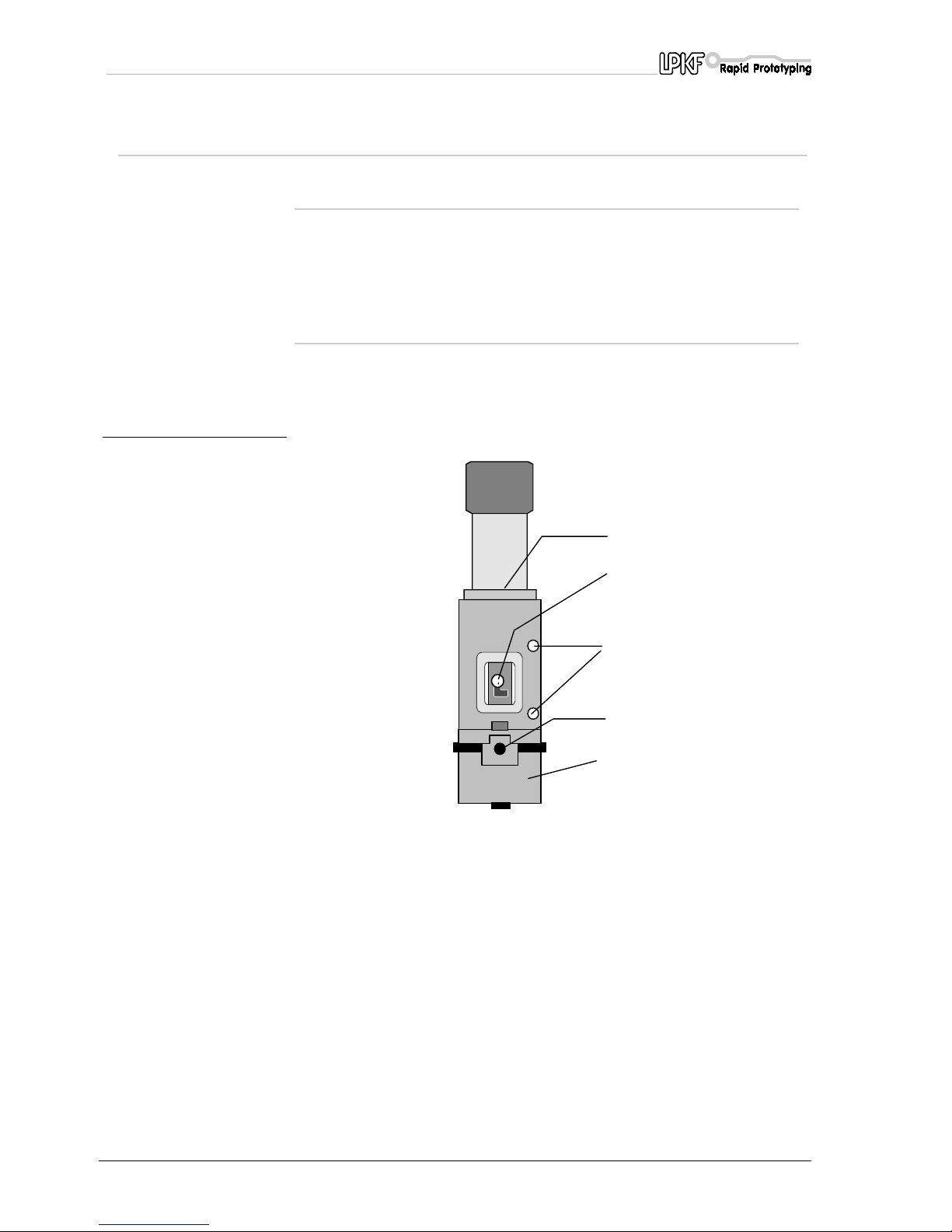
fig. 32:
› Mark the insertion depth of the spindle
(1)
.
› Unscrew and remove the collet lever
(2) (ProtoMat C30/S).
› Undo the Allen screws in the holding block
(3)
.
› The motor can now be lifted out vertically. Gently twist backwards
and forwards if necessary.
› Remove the fixture
(4)
.
› The working depth limiter
(5)
can now be removed to the side for
cleaning.
› Clean both parts of the working depth limiter using the brush
supplied.
5
2
3
1
4
Page 51
Appendix
ProtoMat C30/C30-S 51
› After cleaning, the working depth limiter is reassembled in reverse
order and the motor is reinserted in the retaining block.
› Always check that the insertion depth of the spindle is correct before
starting up.
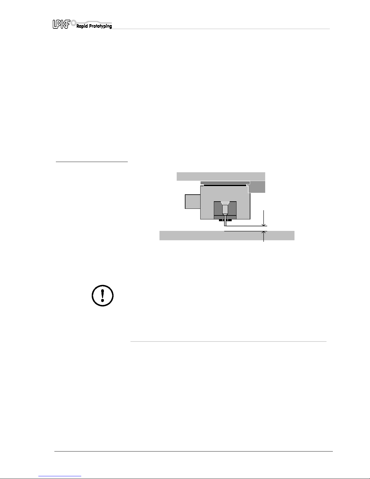
The distance between the drill tip and machine base plate must be 0.5
mm when the head is lowered.
The machine may not be able to drill through the board if the distance is
too great. A larger diameter should be used for the drill because a
smaller drill can easily break as it is being adjusted.
› Finally tighten the screws
(2)
back up and screw the collet lever
(1)
back in
(ProtoMat C30/S)
.
fig. 33:
› Check the distance when reassembling the plotter spindle.
The machine may be damaged if the distance is too small when
drilling.
Caution! Use only graphite to lubricate the working depth limiter.
13.2 Lubricating the carriage guide wipers
You must make sure that the carriage guide wipers on the LPKF
ProtoMat C30 (C30/S)
are always well lubricated.
0.5mm
Page 52
Appendix
52 ProtoMat C30/C30-S
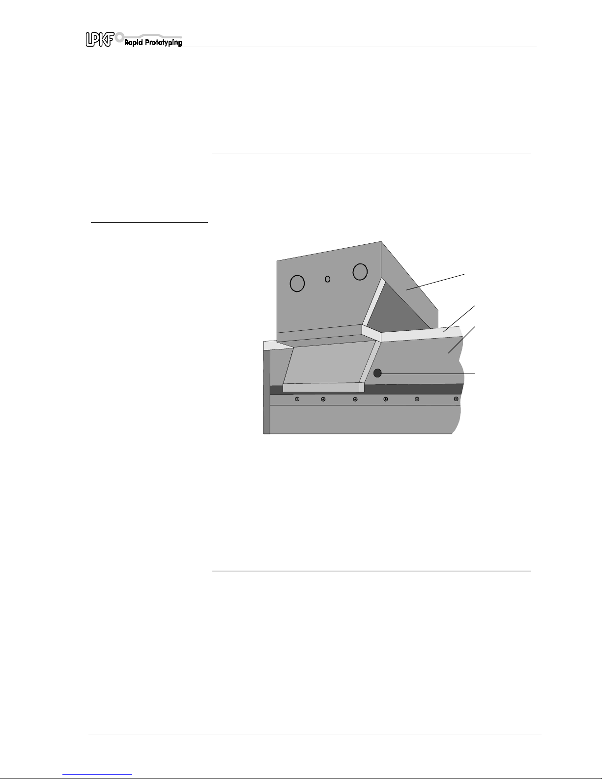
13.2.1 Carriage guide wipers of the Y-axis
› Drive the cutting head in the Homeposition, before the Y-axis will be
lubricated.
› Before the lubrication the Y-axis you must loose the cover located
internal hexagon head screws (3mm).
› After remoting the screws take off the cover.
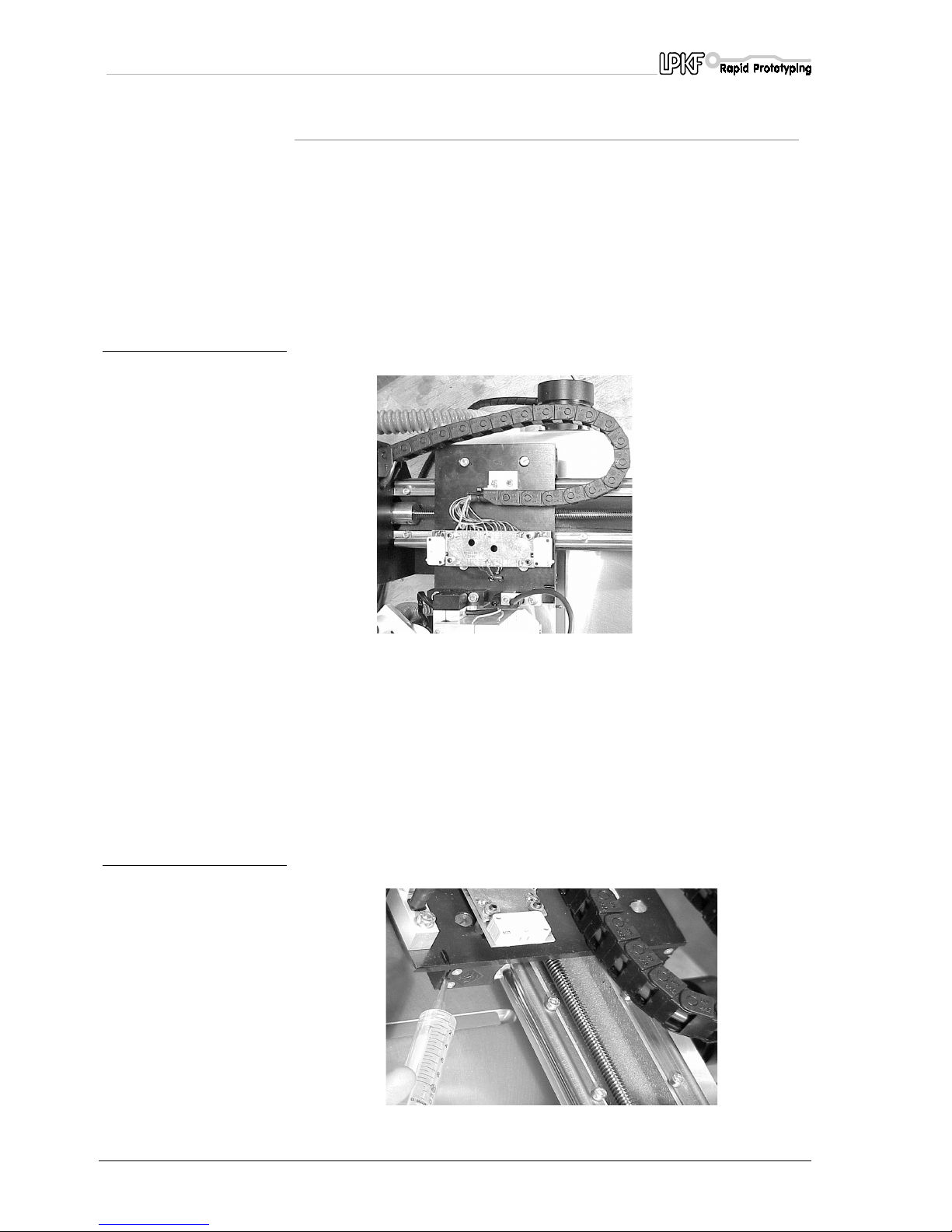
The positions of the oil insertion opening for the carriage guide wipers of
the Y-axis are marked in the following image with arrows:
fig. 34:
For the lubrication you have to use an acid-free precision mechanic - oil!
Stick the dosing neadle (conical grey) on the on-time syringe (delivered
with the mashine).
In the following image you can see the construction.
Now you have to lubricate all four carriage guide wipers of the Y-axis
with the help of the one-time syringe (See following image). The
prescribed quantity of oil for one carriage guide wiper totals 0,5 ml.
fig. 35:
Page 53
Appendix
ProtoMat C30/C30-S 53
› After lubricating the 4 carriage guide wipers you must plug in and
mount the cover.
13.2.2 Carriage guide wipers of the X-axis
The wipers (4 in total) are located on both sides of the carriage both in
front of and behind the guide cheeks.
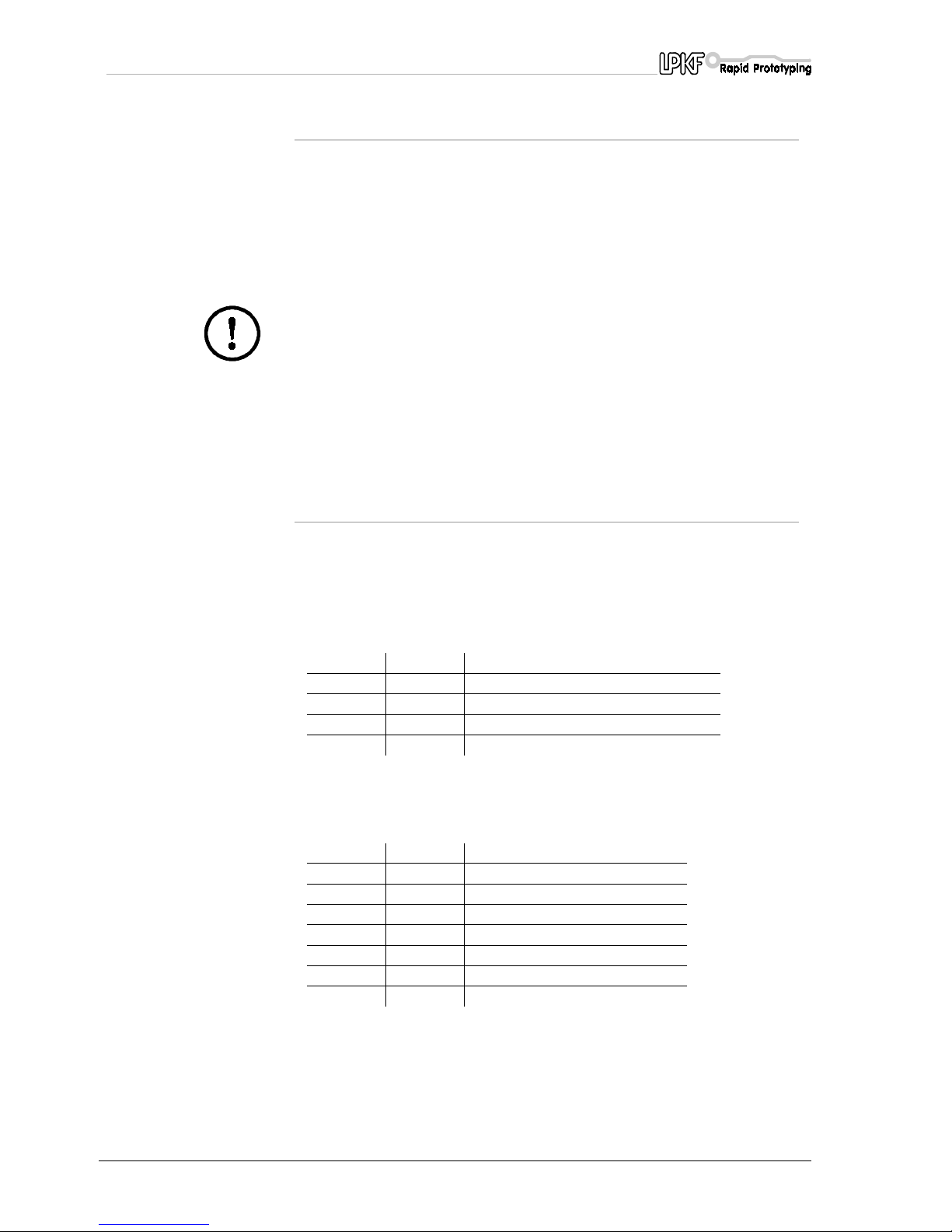
A hole has been drilled on the left and right of the guide rail cover to
allow access these wipers.
fig. 36:
13.2.3 Oiling the rear wipers
› Move the carriage to the tool change position.
The supply ports are now behind the guide wall. Use the syringe to
inject oil through the port and into the hole on both sides of the wiper.
1-
tool carriage
2
- Machine base plate
3
- cover for guide rails
4
- supply port
1
2
3
4
Page 54
Appendix
54 ProtoMat C30/C30-S
13.2.4 Oiling the front wipers
› Move the carriage
112 mm to the rear (+X)
of the tool change
position.
The supply ports is now located in front of the guide wall and the
wipers can be oiled using the syringe (0,5 ml).
Caution! Wipe any excess oil from the casing as it might corrode
the paintwork. Never move the carriage manually. Doing so could
cause the output stages of the stepping motors to be damaged by
induced voltage.
13.3 SerialPort 1 serial connection
The SerialPort1 serial data channel is an RS 232-C standard port with
electrical isolation and is used for communication between the control
unit and the PC.
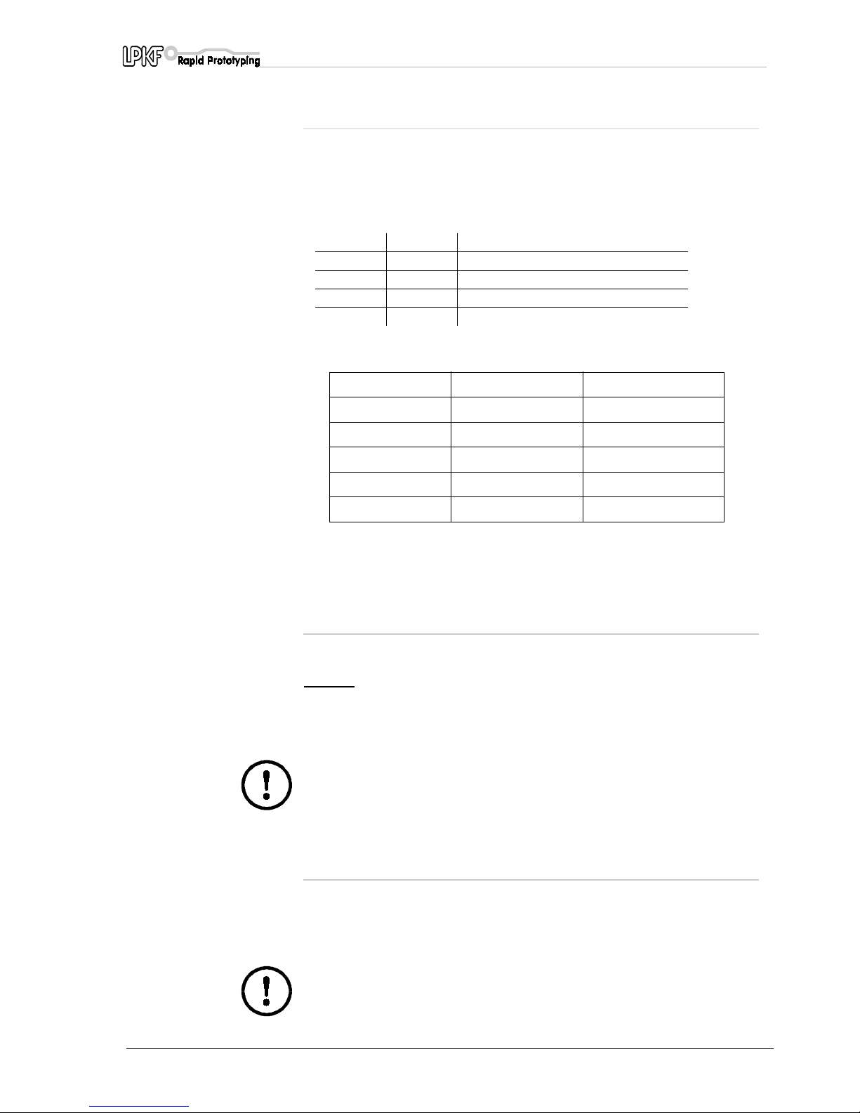
The SerialPort1 data transmission rate is programmed using DIL
switches 1 and 2.
SerialPort1 pinouts:
A signals are electrically isolated; all contacts not mentioned are not
used.
Switch 1 Switch 2 Baud rate
OFF OFF 4800 baud
ON OFF 9600 baud Default setting
OFF ON -
ON ON -
Pin Signal Meaning
2 TXD Transmit Data
3 RXD Receive Data
4 RTS Request to Send
5 CTS Clear to Send
7 GND-I Ground (isolated)
8 DCD Data Carrier Detect
20 DTR Data Terminal Ready
Page 55
Appendix
ProtoMat C30/C30-S 55
13.4 SerialPort2 serial connection
The SerialPort2data channel is an RS 232-C standard port and can be
used for communication between the control unit and another system.
The SerialPort2 data transmission rate is programmed using DIL
switches 3 and 4.
SerialPort2 pinouts:
Any pin not mentioned is not used.
13.5 Connecting the stepping motors
The stepping motors are connected on each axis using a 15-pin SUB-D
connector. If a limit switch is actuated, any further axis movement
towards
the limit switch is immediately blocked.
The position of the sockets is described in the section entitled
"LPKF ProtoMat 91S displays and connections".
Caution! Never confuse the cable for the stepping motor and the
plotter head.
13.6 Connecting the plotter head
The plotter head is connected to the control unit with a 15-pin socket.
The position of the socket is described in the section entitled "LPKF
ProtoMat 91S displays and connections".
A further 5-pin cable supplies the plotter spindle.
Caution! Never confuse the cable for the stepping motor and the
plotter head.
Switch 3 Switch 4 Baud rate
OFF OFF 4800 baud
ON OFF 9600 baud Default setting
OFF ON -
ON ON -
PIN Signal Meaning
3 TXD Transmit Data
2 RXD Receive Data
7 RTS Request to Send
8 CTS Clear to Send
5 GND Ground
Page 56
Appendix
56 ProtoMat C30/C30-S
13.7 EPROMs
The software for the control unit is held on two EPROMs.
The LPKF
ProtoMat C30 (C30/S)
must be partially dismantled if the
EPROMs need to be replaced.
Proceed as described under "Removing the electronics unit".
Use only an PLCC pliers to remove the EPROMs as otherwise the
mounting contacts might be damaged.
Support the board from below when inserting new EPROMs to avoid
bending the board. Take care that the orientation of the EPROMs is
correct.
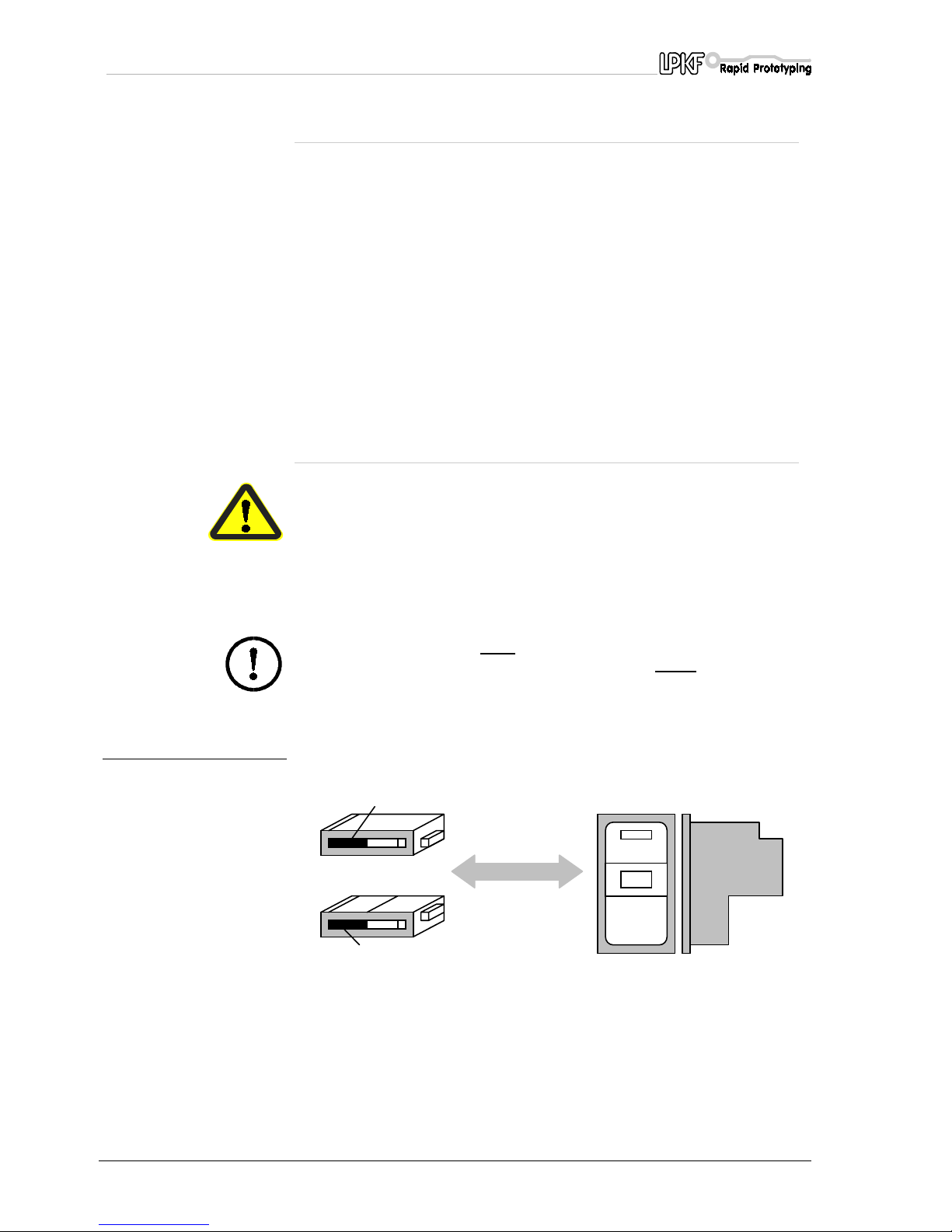
13.8 Switching the device voltage,
electrical fuses
Danger! Make sure that the mains connector is removed before
working on the fuses or opening the device.
The primary and secondary voltages on the LPKF ProtoMat C30 (C30/S)
are fused. The mains (primary) fuses are in the control unit power
connection and can be accessed from the outside.
Caution! Make sure that
both
fuses are replaced when switching to
another line voltage. Both fuses must have the
same
rating.
fig. 37: Setting the voltage and
fuses
The secondary fuses are inside the control unit.
The control unit must be removed from the mechanism before replacing
the fuses. Proceed as described under "Removing the electronics unit".
Page 57
Appendix
ProtoMat C30/C30-S 57
13.9 Removing the electronics unit
The control unit must be isolated from the mechanism.
First move the plotter head to the
TOOL CHANGE
position if the plotter
head is still attached. Now use the arrow buttons to move the crossbar to
the centre of the machine base plate.
Caution! The head must not be in either the TOOL CHANGE or
Home position and the limit switches must have been cleared.
Switch off the circuit board plotter and disconnect the device from the
mains by removing the mains connector.
fig. 38: Position of screws for
removing the electronics
unit from the mechanism
› Undo the electric connections between the mechanism and the
control unit. Tilt the circuit-board plotter towards the head.
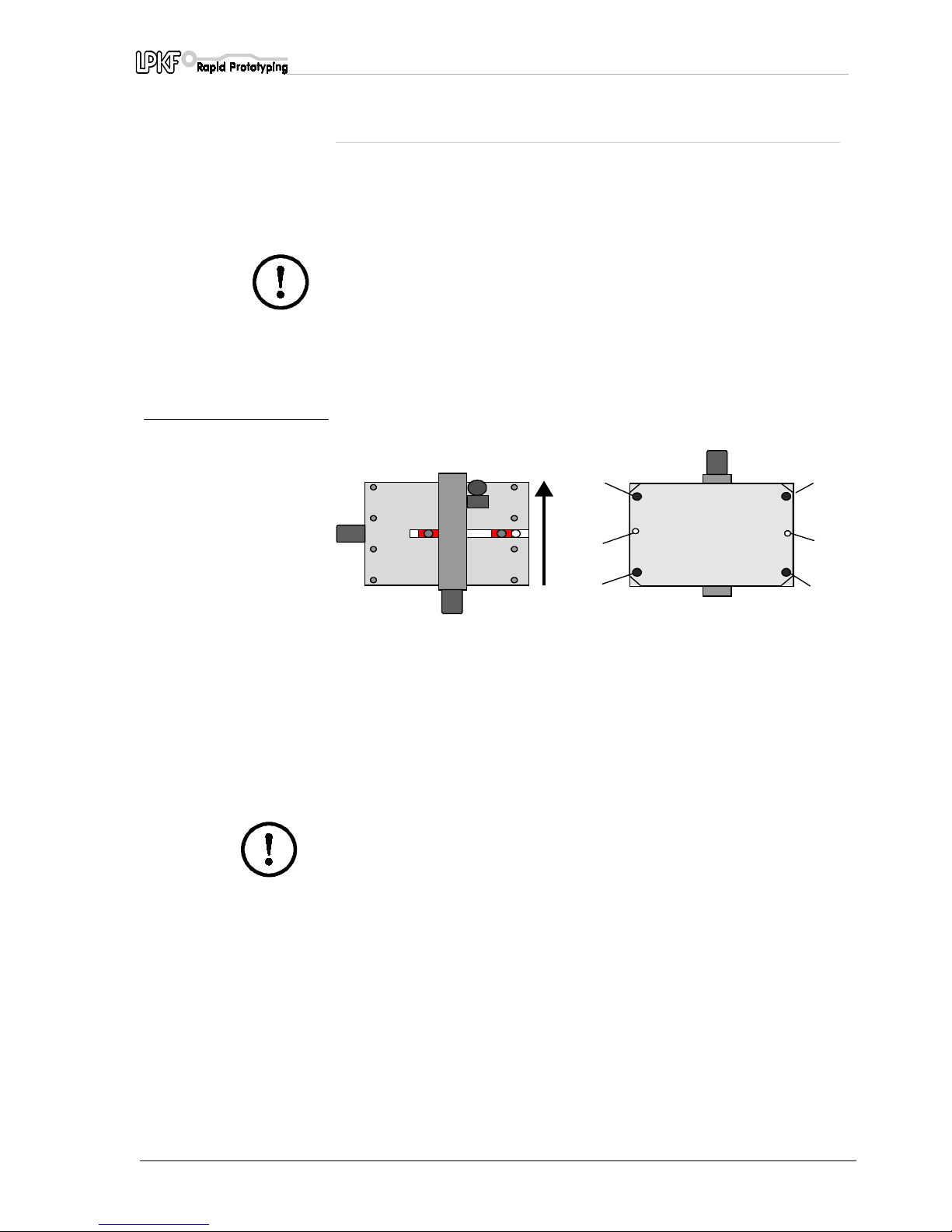
› Undo feet 1, 2, 3, 4 and the Allen screws 5, 6 on the underside of the
machine. Remove the cover with the limit switches. The control unit
has now been released.
Caution! Check that the machine is disconnected from the mains
by removing the mains connector.
1
2
3
4
5
6
Kippen
Page 58
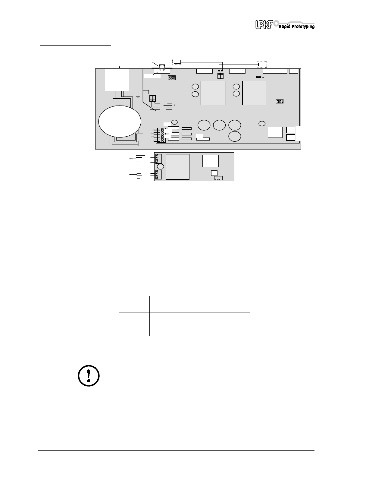
Appendix
58 ProtoMat C30/C30-S
fig. 39: View of the LPKF ProtoMat
C30 (C30/S) circuit board
The secondary circuits are protected by microfuses as follows:
The units are reassembled in the opposite order to that described above
for disassembly.
Caution! Never confuse the cable for the stepping motor and the
plotter head. Always check that head and motor cables are
connected correctly before switching on.
The fuses for the primary circuit are in the power switch, which also
contains the mains filter and the power selector (i.e. 230 V/115 V).
Medium time-lag fuses must be used:
• 230V fused with 1.6A
• 115V fused with 3.15A
head cable
Power LED
10 pole flat-cable
DC AMP
orange
red
brown
black
DC AMP
su
pply
violet
oran
g
e
white
g
reen
1.
EMI Filter
Pri 1
∼
Pri 2
Main Fuse 3,15A
+ X
X -
Y - axis X - axis SerialPort 1
SMCU
Limit-Switch located at cover
2 A
5 A
3,15 A
500 mA
+
Dip-Switches
1.
HS-Motor *
on
SerialPo rt 2
Transform er
2
1
3
4
5
67
8
9
10
11
12
13
red
brown
red
oran
g
e
brown
black
oran
g
e
black
DC AMP
suppl
y
HS - Motor
DC AMP
98/1
10 pole flat-cable
SM CU
15
14
701
703
704
705
1
- Mains filter
9
- DIL switches for setting the baud rate (in default setting)
2
- Transformer
10
- PSUs
3
- Transformer connection
11
- Processor
4
- Plotter head power pack
12
- EPROM L
5
- Z axis power pack (bare)
13
- EPROM H
6
- Y axis power pack
14
- EPROM for motor output stage
(electronics under the cover)
7
- X axis power pack
15
- Processor for motor output stage
(electronics under the cover)
8
- Processor section
701-705
Various fuses (see below)
Fuse Type Circuit
F701 3.15 A Power output phases
F703 5.00 A +24 V at I/O-interface
F704 2.00 A +5V and VREF
F705 0.50 A RS 232 C/SerialPort1
Page 59
Appendix
ProtoMat C30/C30-S 59
13.10 The Command set
13.10.1 Command structure
The SMCU (Signal Processor Control Unit) control unit in the machine
interprets the HP-GL commands described below and converts them
into defined actions.
The
machine has a resolution of 7.9375 µm
.
This differs from the resolution used by standard HP-GL plotters. The
use of master commands reduces the output.
The syntax:
The SMCUexpects a separator, which may not be a digit or uppercase
letter, between the command parameters. A new command can follow a
parameter without a separator. The last character transmitted in a
command file must be a semicolon or a line feed character (0A hex.).
Unrecognized commands are ignored by the control unit, but their
parameters can lead to unwanted plot absolute or plot relative
commands.
Symbol Meaning
{...} The contents can be repeated any number of times.
() The command parameters are contained within these brackets.
[] The content of these brackets is optional and does not have to be
included.
Page 60

Appendix
60 ProtoMat C30/C30-S
13.10.2 HP-GL standard commands
AA (x,y,a{,ß}){;}
Arc Absolute
Draws an arc around the absolute coordinate (x,y) starting from
the current position with the arc angle a=[degrees]. It is drawn
clockwise where the arc angle a is negative, but otherwise it is
drawn anti-clockwise.
AR (x,y,a{,ß}){;}
Arc Relative
Draws an arc around the relative coordinate (x,y) starting from the
current position with the arc angle a=[degrees]. It is drawn
clockwise where the arc angle a is negative, but otherwise it is
drawn anti-clockwise.
Cl (r{,ß}){;}
Circle
Dws a complete circle with radius r around the current position.
Resolution ß is ignored as the maximum resolution is always used
when drawing.
EA (x,y){;}
Edge Rectangle Absolute
Draws a rectangle defined by two corner points diagonally
opposite each other. The first corner point is determined by the
current position and the second by the absolute coordinate (x,y).
ER (x,y){;}
Edge Rectangle Relative
Draws a rectangle defined by two corner points diagonally
opposite each other. The first corner point is determined by the
current position and the second by the relative coordinate (x,y).
IN {;}
Initialize
Returns the control unit to the its status after switching on. This
restores all default settings.
IW (x0,y0,x1,y1){;}
Input Window
Restricts the XY axis working area to a window with the corner
coordinates specified.
OH {;}
Output Hard Clip Limits
The control automatically determines its maximum travel range
within the limit switches and sends the coordinates thus
determined to the PC as an ASCII string in the form
("W Xmin,Ymin,Zmin,Xmax,Ymax,Zmax <cr>").
OS {;}
Output Status
The control unit sends its status cell to the PC in ASCII hex ("S
xxxx <cr>").
Page 61

Appendix
ProtoMat C30/C30-S 61
PA (x1,y1{,...xn,yn}){;}
Plot Absolute
Draws a line from the current position to the absolute coordinates
specified in sequence. The PU and PD commands can be
specified as parameters between the coordinate pairs. The PA
command word is not necessary if additional coordinate pairs are
sent. All coordinate pairs without a command word are taken to
relate to the last PA or PR commands sent and are executed
accordingly.
PD {;}
Pen Down
Lowers the tool.
PR (x1,y1{,...xn,yn}){;}
Plot Relative
Draws a line from the current position to the relative coordinates
specified in sequence. The PU and PD commands can be
specified as parameters between the coordinate pairs. The PA
command word is not necessary if additional coordinate pairs are
sent. All coordinate pairs without a command word are taken to
relate to the last PA or PR commands sent and are executed
accordingly.
PU {;}
Pen Up
Raises the tool.
VS (v{,n}){;}
Velocity Select
Defines the track speed v=[µm/s] in the XY-plane with the tool
lowered and assigns this speed to the tool with number n.
13.10.3 Special commands
All special commands begin with the "!" character and their syntax is
otherwise the same as that for HP-GL standard commands.
!AS (a){;}
Acceleration Set
Dines a new acceleration constant a=mm/s2. The permissible
value range is 10 to 50000.
!CC {;}
Close Channel
Terminates any data transfer introduced with the command !OC.
!CM (n){;}
Change Mode
Toggles between the drill (n=0) and the mill working modes (n=1).
!CT (n){;}
Command Counter
Toggles between the echo mode (n=1) and the non-echo mode
(n=0). In echo mode, the machine confirms every correctly
completed command with the message "C<cr>".
!EM (n){;}
External Motor
Switches the milling/drilling motor on (n=1) or off (n=0)
Page 62

Appendix
62 ProtoMat C30/C30-S
!ES (n){;}
Enable Stop
Enables (n=1) and locks (n=0) the external stop function. The
external stop function is locked immediately after switching on.
!FP {;}
Full Power
Switches the XYZ axis motors to full power.
!HP {;}
Half Power
Switches the XYZ axis motors to half power.
!OC {;}
Open Channel
Opens direct data transmission from the SerialPort1 serial data
channel to the SerialPort2 serial data channel. All characters
received on the SerialPort1 data channel are sent to the
SerialPort2 data channel until the !CC character string is received.
!ON (a){;}
Output Nominal Position
The control unit sends the nominal position (target position) of the
motor axis addressed with parameter a. The following addresses
are attributed to the motor axes:
0 = X, Y, Z axis
1 = X axis
2 = Y axis
3 = Z axis
!RD (a){;}
Read Port
Forces a read on the input port with the
address a=<0..15>. The data is output as ASCII numbers through
the serial port which the command originated.
!RS (r){;}
Resolution Set
Tells the control unit the machine's step size (r=µm/step). The
permissible value range is 1 to 32000.
!TA (x,y,z){;}
Plot Three-D Absolute
Executes out a spatial movement from the current position to the
absolute coordinate (x,y,z).
!TD (t1,t2,t3,t4){;}
Time for Drilling
Sets a new drilling time t=[ms].
!TM (t1,t2,t3,t4){;}
Time for Milling
Sets the new milling time t=[ms].
!TR (x,y,z){;}
Plot Three-D Relative
Executes a spatial movement from the current position to the
relative coordinate (x,y,z).
!TS (t){;}
Time to Stabilize
Sets a stabilization time t=[ms] between the individual commands.
Page 63

Appendix
ProtoMat C30/C30-S 63
!TW (t){;}
Time to Wait
The next command is only executed once the waiting time t=[ms]
has expired.
!VU (v){;}
Velocity if Pen Up
Defines the track speed v=[µm/s] of the motion in the XY plane
when the tool is raised.
!VZ (v){;}
Velocity Z axis
Defines the speed v=[µm/s] of the movement in the Z axis.
!WR (a,d{,m}){;}
Write Port
Writes the data word d to the port with address a=<0..15> with the
option of assigning a bit mask.
!ZA (z){;}
Plot Z axis Absolute
Moves the Z axis from the current position to the absolute
coordinate (z).
!ZR (z){;}
Plot Z axis Relative
Moves the Z axis from the current position to the absolute
coordinate (z).
13.10.4 Special command for the motor controller
The command to open the SerialPort2 (!OC;) must be processed before
communication can take place with the plotter spindle drive motor, after
which the SerialPort2 serial port must be closed again (!CC;)
!RM (r){;}
Revolutions Motor, r=0...32.
Sets the speed (r)*1000 of the DC motor.
13.10.5 Direct commands
Direct commands are special commands which are executed by-passing
the command buffer immediately they are interpreted.
!CB{;}
Clear Buffer
Deletes all commands from the command buffer.
!GO{;}
Go On
Clears the stop command and continues command execution.
!RC{;}
Repeat Command
Repeats the most recently executed command.
Page 64

Appendix
64 ProtoMat C30/C30-S
!ST{;}
Stop
Interrupts the execution of commands once the current command
has completed.
The command set implemented is a subset of the HP-GL. Be
aware when controlling the device from any other CAD system that
the resolution of the HP-GL commands is substantially smaller
than that of normal pen plotters.
The step size is 7.9375 µm/step. (6.35 mm/800 steps).
Page 65

Appendix
ProtoMat C30/C30-S 65
13.11 Table of available tools
Tools marked with an asterisk (*) are available for the LPKF
ProtoMat
C30 (C30/S)
.
Name Diameter in mm Length 36mm
38 mm
Delivery time
S = stock part
Universal milling cutter 0.2 - 0.4 * S
Micromill 0.1 - 0.2 * S
RF cutter (Milling layout films) 0.25 * S
Contour milling cutters 1.0 * S
2.0 * S
3.0 * S
Double chamfered cutters 0.8 * S
1.0 * S
2.0 * S
3.0 * S
Drills 0.3 * S
0.4 * S
0.5 * S
0.6 * S
0.7 * S
0.8 * S
0.9 * S
1.0 * S
1.1 * S
1.2 * S
1.3 * S
1.4 * S
1.5 * S
1.6 * S
1.7 * S
1.8 * S
1.9 * S
2.0 * S
2.1 * S
2.2 * S
2.3 * S
2.4 * S
2.5 * S
2.6 * S
2.7 * S
2.8 * S
2.9 * S
2.95 *
3.0 * S
Page 66

Concluding remarks
66 ProtoMat C30/C30-S
14.0 Concluding remarks
The European Community Machinery Directive 93/44 dated 14 June
1993 has been used as a basis for this manual.
Where reference has not been made to the EC Directive in any section,
we hereby refer the reader to the relevant paragraphs of the Directive
and any claims concerning completeness and liability are excluded.
Furthermore, we hereby draw attention to all remaining risks unknown to
the manufacturer which might occur due to incorrect use of the machine.
LPKF shall not be held responsible for damage resulting from use of the
LPKF
ProtoMat C30 (C30/S)
.
This also applies where reference has been made to such damage.
Page 67

Konformitätserklärung für LPKF ProtoMat C30 (C30/S)
ProtoMat C30/C30-S 67
15.0 Konformitätserklärung für LPKF ProtoMat C30 (C30/S)
1.
Hersteller der mit LPKF ProtoMat C30 (C30/S) bezeichneten
Maschineist die Firma:
LPKF
Laser & Electronics AG
Osteriede 7
D-30827 Garbsen
2.
Bei der mit LPKF
ProtoMat
C30 (C30/S) bezeichneten Maschine
handelt es sich um einen Fräsbohrplotter, der zum Erstellen von
Leiterplattenprototypen und Gravurfilmen, sowie zum Gravieren
von Aluminium oder Kunststoff geeignet ist. Die Seriennummer der
vorstehenden Maschine ist 1F............(siehe auch Bodenplatte).
Weitere Angaben zur LPKF
ProtoMat
C30 (C30/S) sind dem
beiliegenden Handbuch zu entnehmen.
3.
Die LPKF
ProtoMat
C30 (C30/S) entspricht den Bestimmungen der
EG-Maschinenrichtlinie 93 / 68 vom 22. Juli 93, der EGNiederspannungsrichtlinie ( 73 / 23 / EWG ) und der EG-Richtlinie
EMV ( 89 / 336 / EWG ).
4.
Die LPKF
ProtoMat
C30 (C30/S) ist nach dem Stand der Technik
und nach den anerkannten sicherheitstechnischen Regeln gebaut
worden. Bei der Erstellung fanden auch bestehende DINVorschriften Anwendung.
5.
Bevollmächtigter Unterzeichner dieser Erklärung ist
Herr Bernd Hackmann
Vorstand LPKF AG
Osteriede 7
D-30827 Garbsen
Bernd Hackmann
Page 68

Konformitätserklärung für LPKF ProtoMat C30 (C30/S)
68 ProtoMat C30/C30-S
15.1 Declaration of conformity
1.
The manufacturer of the machine identified as the LPKF
ProtoMat
C30 (C30/S)
is:
LPKF
Laser & Electronics AG
Osteriede 7
D-30827 Garbsen, Germany
2.
The machine identified as LPKF
ProtoMat C30 (C30/S)
is a circuitboard plotter, suitable for the production of circuit board prototypes
and engraving films, as well as for the engraving of aluminium or
plastic. The series number of the above-mentioned machine is
1F............(see also base plate).
Further information on the LPKF
ProtoMat C30 (C30/S)
can be
obtained from the Manual enclosed.
3.
The LPKF
ProtoMat C30 (C30/S)
complies with the requirements of
the of EC Machinery Directive 93/68 dated 22 July 1993, the EC
Low Voltage Directive (73/23/EEC) and EC EMC Directive (89/336/
EEC).
4.
The LPKF
ProtoMat C30 (C30/S)
has been manufactured in
accordance with the state of the art and in accordance with
recognised rules of safety. Existing DIN specifications have also
been applied in the manufacture of the LPKF
ProtoMat C30 (C30/
S)
.
5.
Authorized signatory to this declaration:
Mr. Bernd Hackmann
Managing director LPKF AG
Osteriede 7
D-30827 Garbsen, Germany
Bernd Hackmann
Page 69

Index
ProtoMat C30/C30-S 69
16.0 Index
A
Adjustment
..........................................................................................................18
Alignment pin
.....................................................................................................28
Asynchronous interface
...............................................................................19
B
Baud rate
.......................................................................................................14, 21
Board material
...............................................................12, 22, 23, 29, 30, 31, 37
BoardMaster
............................................................19, 20, 21, 26, 30, 31, 32, 33
C
Carriage guides
................................................................................................51
Caution
....................................................................................................................4
Collet
................................................................................................................16, 39
Lever 31
Configuration diskette
...................................................................................22
Continuous sound pressure level
...........................................................12
Contour milling
................................................................................34, 37, 41, 48
Conventions
.........................................................................................................4
D
Danger
....................................................................................................................4
DC motor
..............................................................................................................39
Declaration of conformity
............................................................................69
Double-chamfered cutter
.............................................................................42
Drilling
....................................................................................................................28
Drilling burr
.........................................................................................................48
E
EPROMs
..............................................................................................................56
F
Faulty sections
..................................................................................................25
Fräsbohrplotter
.................................................................................................68
Functional test
...................................................................................................21
Fuses
.....................................................................................................................56
H
Hardware handshake
....................................................................................21
HOME position
..................................................................................................15
Checking 22
Test program 22
HP-GL
....................................................................................................................61
I
Isolation milling
.................................................................................................40
K
Konformitätserklärung
...................................................................................68
L
Layout film
...........................................................................................................43
Lever for collet
..................................................................................................39
Limit switch
...................................................................................................20, 60
Page 70

Index
70 ProtoMat C30/C30-S
Line voltage
........................................................................................................ 20
M
Machine bed
...................................................................................................... 48
Machine ratings
................................................................................................10
Milling
........................................................34, 35, 37, 38, 40, 41, 42, 43, 48, 49, 61
Milling depth
.....................................................................................31, 37, 38, 48
Milling pass
................................................................................................... 35, 49
Milling phase
................................................................................................ 31, 32
Milling track
........................................................................................................ 25
Milling width
................................................................................................. 40, 48
Milling-drilling plotter
........................................................ 10, 14, 19, 22, 34, 69
Motor
...................................................................... 16, 17, 18, 21, 30, 31, 55, 58, 61
N
Note
..........................................................................................................................4
O
Orientation
............................................................................................................ 4
P
PAUSE position
..........................................................................................15, 24
Pilot pins
.............................................................................................................. 20
Placement dialog box
...................................................................................30
Plotter head
.......................................................................... 18, 27, 28, 37, 55, 58
Postprocessing
................................................................................................. 19
R
Reference
................................................................................................ 15, 22, 37
Reference pin
........................................................................................15, 27, 37
Registration hole
.............................................................................................22
Registration hole slide
............................................................................15, 22
Registration hole strip
.....................................................12, 15, 22, 27, 28, 37
Registration hole system
...............................................15, 22, 26, 27, 28, 37
Residual copper areas
.................................................................................42
Rubout areas
..................................................................................................... 42
S
SeralPort1
........................................................................................................... 54
Serial port
..........................................................................................14, 17, 21, 62
SerialPort1
Pinouts 54
SerialPort2
.......................................................................................................... 55
Pinouts 55
SMCU
....................................................................................................................59
Solder-stop sheet
............................................................................................43
Special commands
.........................................................................................61
Supply ports
....................................................................................................... 54
Switch-on sequence
......................................................................................20
T
Tool change
........................................................................................................ 15
Tool combo box
................................................................................................31
Tool library
.......................................................................................................... 46
Transport securing devices
........................................................................ 13
Traverse range
...........................................................................................20, 32
Traverse speed
..............................................................................41, 42, 43, 48
Page 71

Index
ProtoMat C30/C30-S 71
V
Vacuum
.................................................................................................................40
Vacuum system
............................................................12, 13, 29, 30, 38, 40, 42
Vacuum system connection
.......................................................................17
Vitrification of the drilled hole
....................................................................49
W
Wipers
...................................................................................................................53
Working depth limiter
...........................................16, 17, 18, 27, 30, 31, 38, 50
X
X motor
.................................................................................................................17
Y
Y motor
.................................................................................................................17
Page 72

Index
72 ProtoMat C30/C30-S
 Loading...