

Page 1
32
To better respond to customer requirements and expectations, LPG Systems is constantly looking for
ways to improve the design and quality of its products. For this reason, there may be minor differences
between your equipment and the unit described in this manual.
≥
WARNING
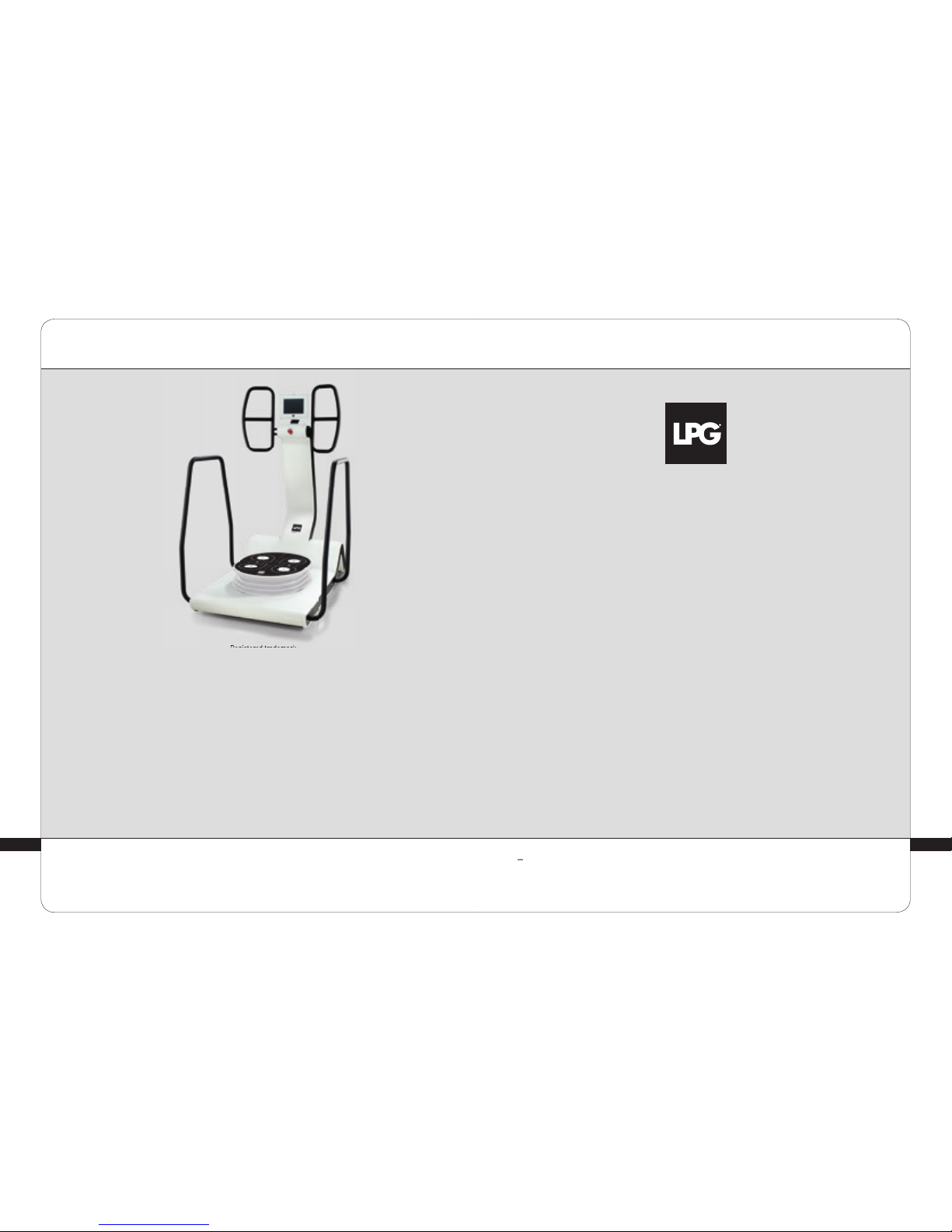
OPERATOR’S MANUAL HUBER 360® EVOLUTION
Registered trademark
Please read this entire manual carefully
before using your device.
© LPG Systems 2018. LPG and HUBER are registered trademarks.
Reproduction, even in part, is strictly prohibited.
Keep this manual and the separate installation
instructions for future reference
GU1306 - GB
Indice B of 10/18
Congratulations on the purchase of your HUBER 360® EVOLUTION device.
This model represents many years of research, combining the latest technologies
with LPG’s expertise. You can fully appreciate the technical perfection and
reliability that have made LPG Systems the leader in this field.
With the aim to continuously provide satisfaction, your device is equipped with
a specific software devised to ensure connection with the LPG dedicated server.
The data collected through this software will allow LPG to improve its support
and maintenance services. This operator’s manual describes how to operate the
device, instructions for periodic maintenance, and safety guidelines.
Your device should be used only by a professional who has completed the
manufacturer’s training provided by LPG Systems or an approved provider, if you
live outside of France, it’s not suitable for home use.
If you have any questions about operating or maintaining your device, please
contact LPG via the Customer Service Department of your local LPG distributor.
Page 2

54
>
One HUBER 360® EVOLUTION
>
One set of guardrails
>
One respositioning block
>
One articulated stool
>
Two pads
>
One heart rate monitor
>
One tablet
>
One power cable
>
One set of quick unpacking and set-up instructions
>
One POS display
1. DEVICE DESCRIPTION .............................................................. 6
2. CONTROL AND ACCESSORIES DESCRIPTION....................................... 8
3. IMPORTANT SAFETY INFORMATION ...............................................21
4. MAINTENANCE .................................................................... 26
5. TROUBLESHOOTING ............................................................... 29
6. TECHNICAL SPECIFICATIONS .....................................................31
7. WARRANTY ........................................................................ 33
8. APPENDIX: ELECTROMAGNETIC COMPATIBILITY .................................37
2.1 Control Screen........................................................... ...... 8
2.2 Handles...................................................................... .. 9
2.3 Platform...................................................................... . 9
2.4 Pads.......................................................................... 10
2.5 Articulated stool (Hu-seat) ....................................................13
2.6 Heart rate monitor ............................................................16
2.7 Tablet .........................................................................17
2.8 Guardrails.................................................................... 18
2.9 Repositioning block..................................................... ......19
3.1 Installation.............................................................. ......21
3.2 Warning................................................. ......................23
3.3 Precautions........................................................ ...........24
3.4 Contra-indications....................................................... .....25
3.5 Electromagnetic Compatibility............................................ ....26
4.1 Cleaning the device........................................................ ...28
4.2 Identification nameplate........................................... ...........28
4.3 Power cord............................................................... .... 29
1.1 Intended use........................................................ ........... 6
1.2 Presentation................................................. .................. 7
>
CONTENTS
>
CONTENTS
Page 3
76
≥
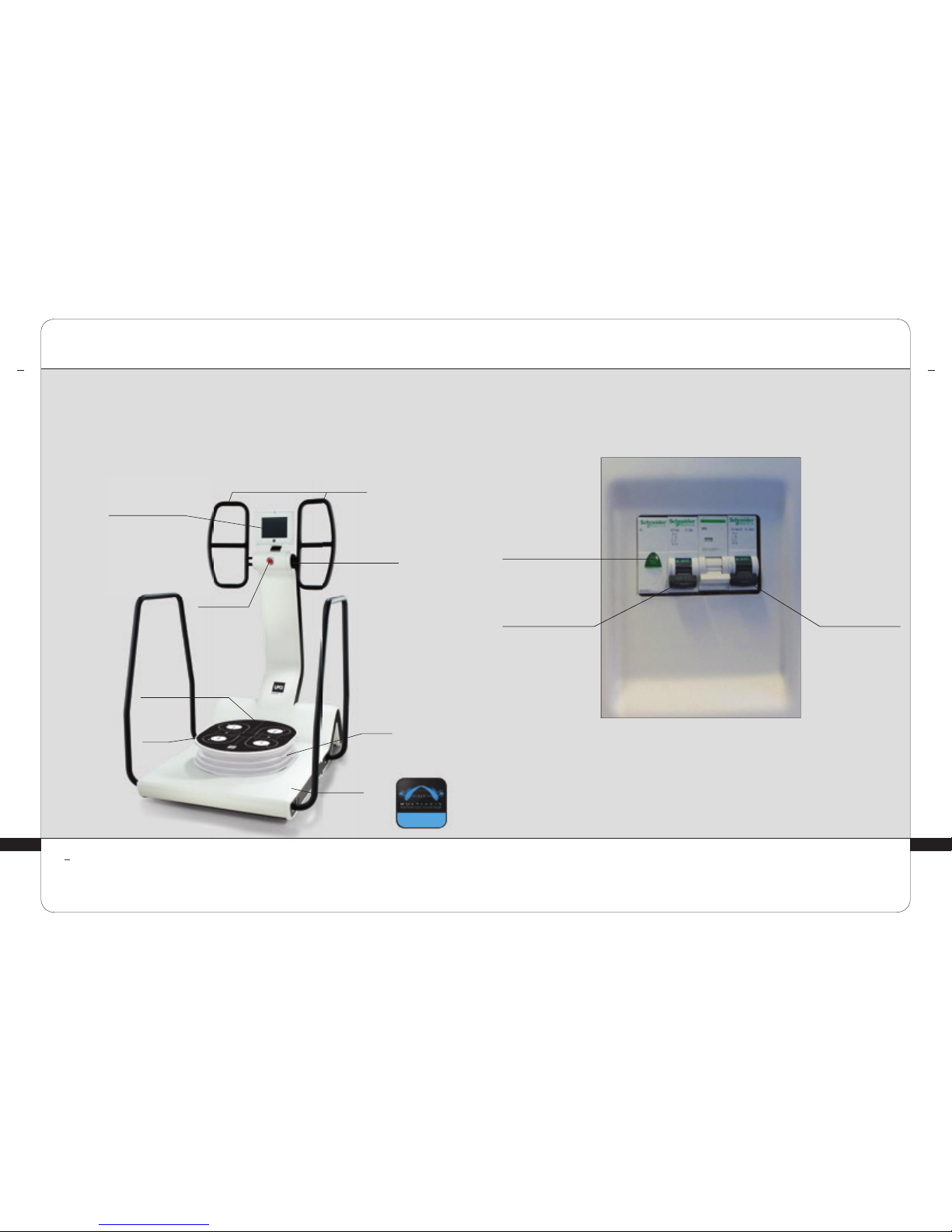
HANDLES
MEASURING
SYSTEM
PLATFORM
BASE
EMERGENCY
STOP BUTTON
TOUCHSCREEN
INTERFACE
BELLOWS
MEASURING
SYSTEM
The unit can only operate if its power cable is connected to the power outlet and if the on/off switch
is turned on.
WARNING
>
DEVICE DESCRIPTION
DEVICE DESCRIPTION
1
HUBER 360® EVOLUTION is intended for therapeutic use. It can be used for:
1. The muscle reinforcment
2. The joint mobility recovery
3. The additional therapy treatment for obesity
The machine can be used in hospitals and rehabilitation clinics by specialists and physiotherapists.
It is an independent device that cannot be combined with other machines. It should only be used by
professionals who have been specially trained by LPG Systems in its use. It is not meant to be used
at home.
1
>
DEVICE DESCRIPTION
DEVICE DESCRIPTION
INDICATOR
POWER ON
CIRCUIT BREAKER
POWER SWITCH NO. 1
TURN ON
FIRST
CIRCUIT BREAKER
POWER SWITCH NO. 2
TURN ON
SECOND
LPG® PATENT
Page 4
98
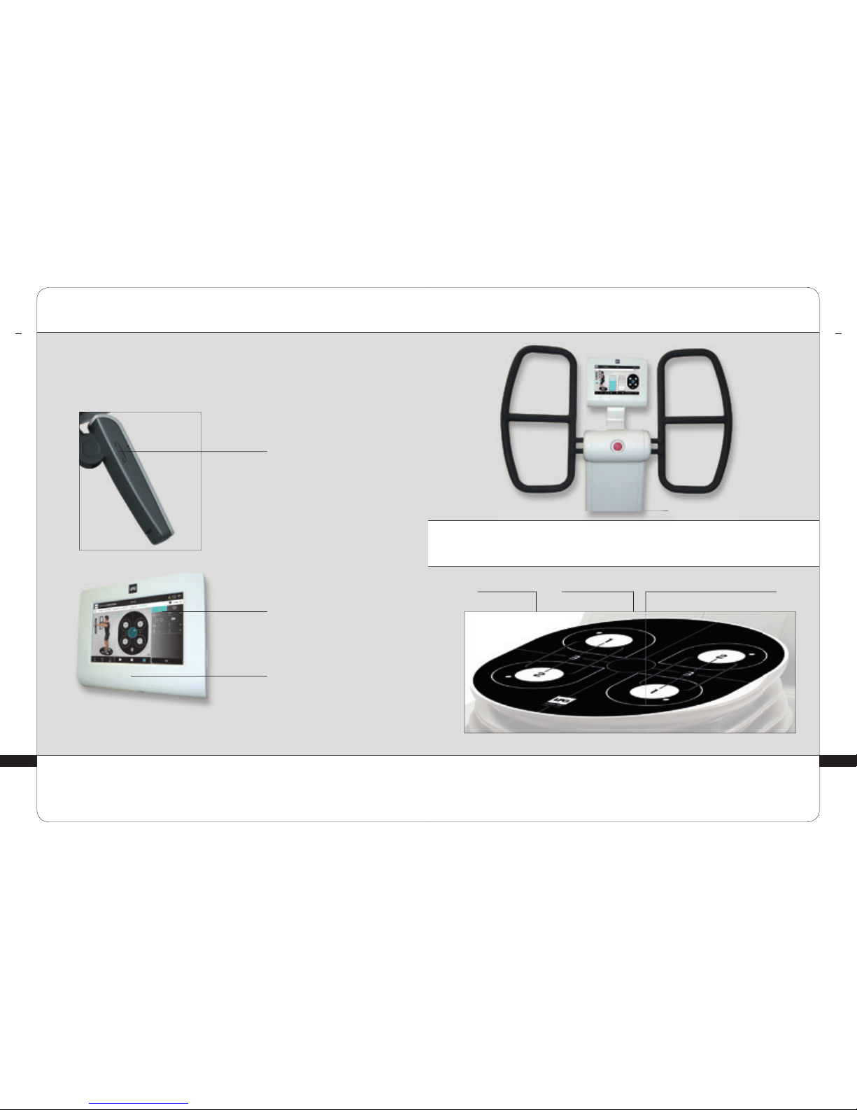
TOUCH SCREEN
POWER INDICATOR
USB PORT
>
HANDLES
>
PLATFORM
CONTROLS AND ACCESSORIES
PLATFORM LEVELPOSITIONING
MARKERS
ACCESSORIES POSITIONING HOLES
2
>
CONTROL SCREEN
CONTROLS AND ACCESSORIES
2
Page 5
1110
2
>
PADS
CONTROLS AND ACCESSORIES
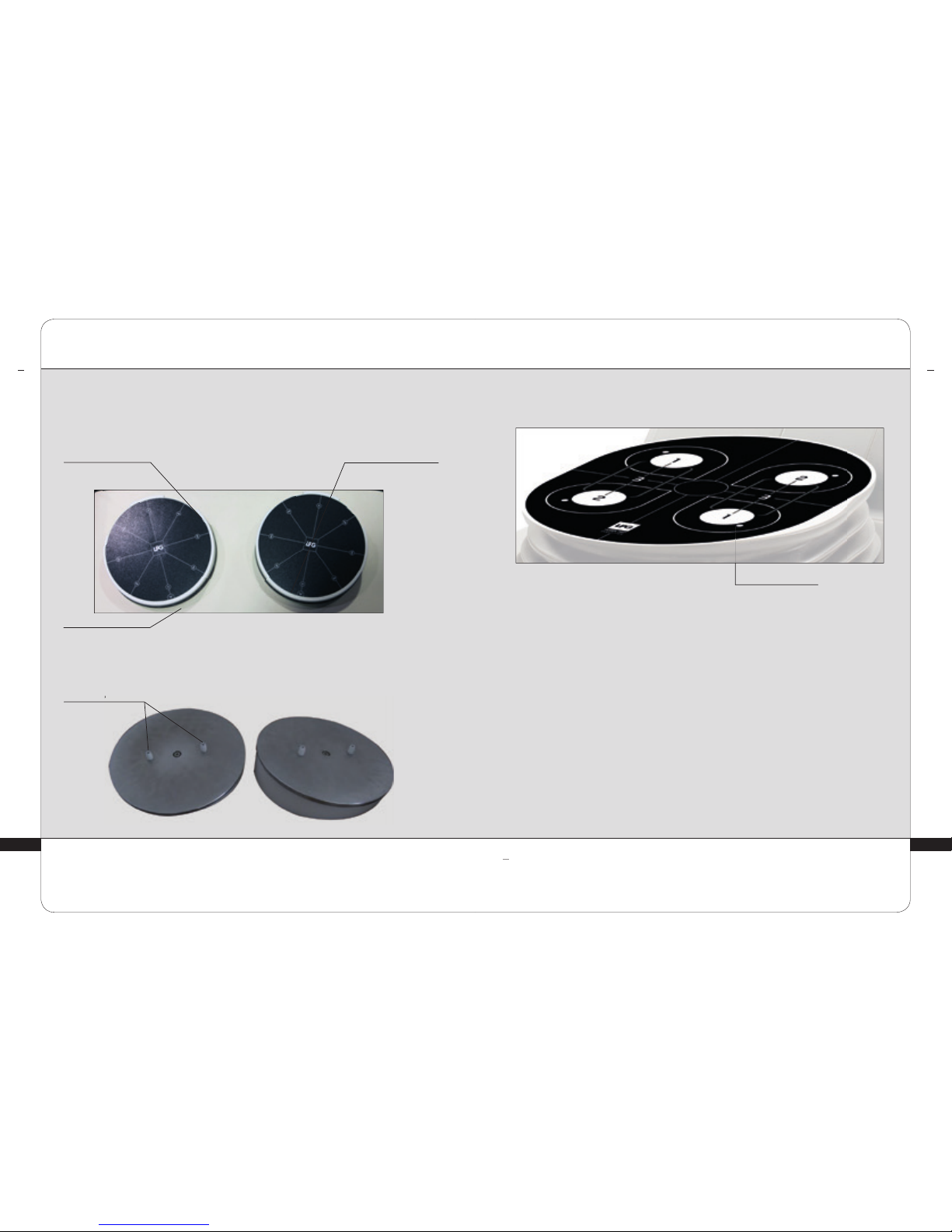
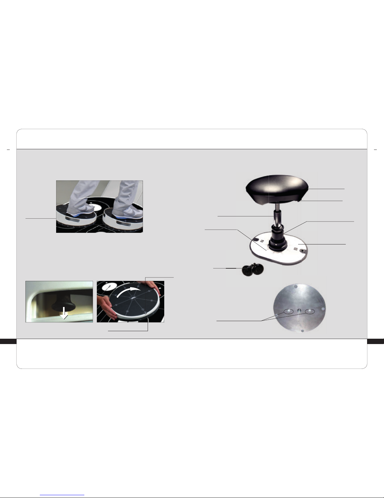
HUBER 360® EVOLUTION comes with two Pads that can be positioned on the
platform.
Underside
POSITIONING
PINS
FOOT ORIENTATION ANGLE
MARKER
PAD ROTATION ANGLE
MARKER
Overview
ORIENTATION MARKER ON
THE UPPER MOVABLE SIDE
2
≥
CONTROLS AND ACCESSORIES
>
PADS (CONT.)
All operations in this section should be performed when the device is powered off.
WARNING
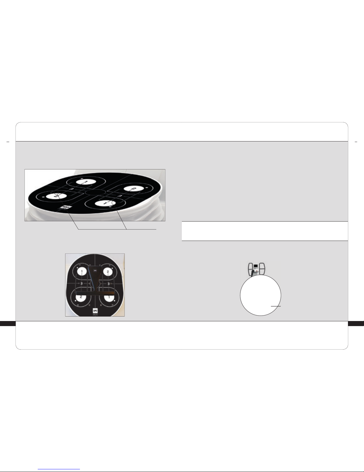
The Pads can be positioned on the platform in the positioning holes.
To position the Pads on the platform, you will need to align the positioning pins on
the Pads with the suitable positioning holes.
POSITIONING THE PADS:
POSITIONING HOLE
Page 6
1312
> PICTURE 1 > PICTURE 2
2
CONTROLS AND ACCESSORIES
>
PADS (CONT.)
The orientation of the Pads with respect to the platform can be adjusted in 15°
increments. To adjust the orientation of the Pads, you will need to unlock the locking
ring by pushing it downwards (photo 1), and then rotate the upper part of the Pads
so that the marker lines up with the proper degree of tilt (photo 2).
ORIENTATION OF FOOTINGS ON THE PAD:
The orientation of the footing can vary 0 to 90° with respect to the inclination of
the Pad. To do this, simply position the footing to the desired angle.
FOOTING
DIRECTION
ORIENTATION OF THE PADS:
PAD ROTATION ANGLE
DIRECTION MARKER ON
THE MOVABLE TOP SECTION
2
CONTROLS AND ACCESSORIES
>
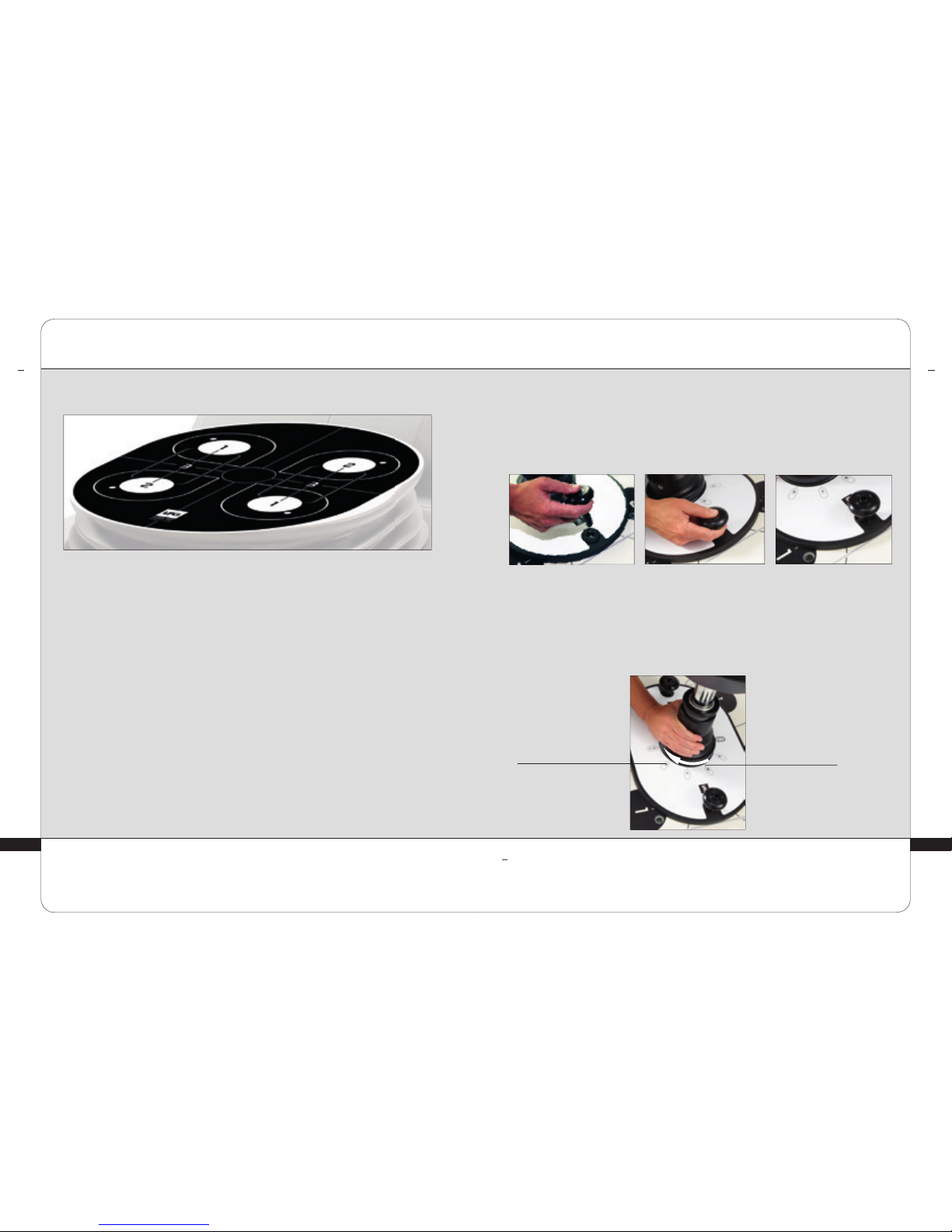
ARTICULATED STOOL
Your HUBER 360® EVOLUTION comes with an articulated stool that can be
positioned on the platform
SEAT
ARTICULATED
STOOL TILT
ANGLE MARKER
TILT ADJUSTMENT
WHEEL
BASE
POSITIONING
PINS
Overview
Underside
LOCK NUTS
PNEUMATIC
JACK
HEIGHT ADJUSTMENT
HANDLE
Page 7
1514
≥
CONTROLS AND ACCESSORIES
>
ARTICULATED STOOL (CONT.)
To position the articulated stool on the platform, you will need to align the
positioning pins on the articulated stool with the suitable positioning holes.
POSITIONING THE ARTICULATED STOOL
2 2
CONTROLS AND ACCESSORIES
>
ARTICULATED STOOL (CONT.)
LOCKING THE ARTICULATED STOOL ONTO THE PLATFORM
Before use, the articulated stool must be locked onto the platform. To do this, press
the middle button until the tool is lodged into the holes, as shown in the photos below:
Ensure that the articulated stool is properly locked before use.
All operations in this section should be performed when the device is powered off.
WARNING
TILT ANGLE
TILT MARKER
The articulated stool can tilt from 0 to 15°.
To do this, turn the articulated stool’s adjustment wheel to set the marker to the
desired tilt.
TILTING THE STOOL
Page 8
1716
The heart rate meter is designed only for casual use. It should not be used for obtaining measurements that
require professional or laboratory-quality precision.
The serial number for the heart rate meter can be found on the back of the belt.
The heart rate monitor contains a battery that cannot be disposed of with household garbage, it requires special
recycling. When the battery dies, dispose of it in an authorized location for recycling.
≥
ATTENTION
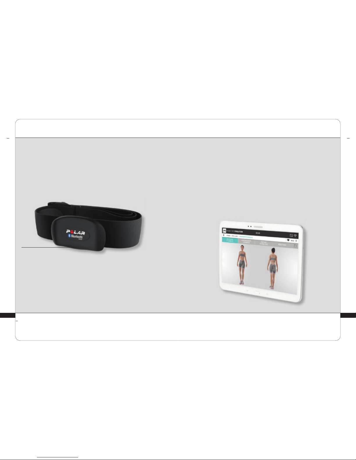
Your HUBER 360® EVOLUTION comes with a Heart Rate Monitor that constantly
displays your heart rate.
Activate your Heart Rate Monitor by centering it on your chest.
Moisten contact areas with water or gel. Next, follow the instructions on the
screen.
Your heart rate will appear at the lower right corner of the screen.
CARDIO BELT TO
BE POSITIONED
ON THE CHEST
Heart Rate
· Display: 30 to 240 bpm
· Limit: 30 to 230 bpm
· Maximum percentage for display: 240 bpm
>
HEART RATE MONITOR
2
CONTROLS AND ACCESSORIES
2
CONTROLS AND ACCESSORIES
>
TABLET
Your HUBER 360® EVOLUTION comes with a tablet that alllows you to access the
HUBER 360® application.
The HUBER 360® EVOLUTION application is downloadable thanks to the «my LPG»
application, available on the Play Store.
This application enables you to:
- carry out a functionnal assessment
- create customised exercises/programmes
- monitor patient at a distance
- send assessment to patients and prescribers
Details about how to use the application are provided when you open it.
Page 9
1918
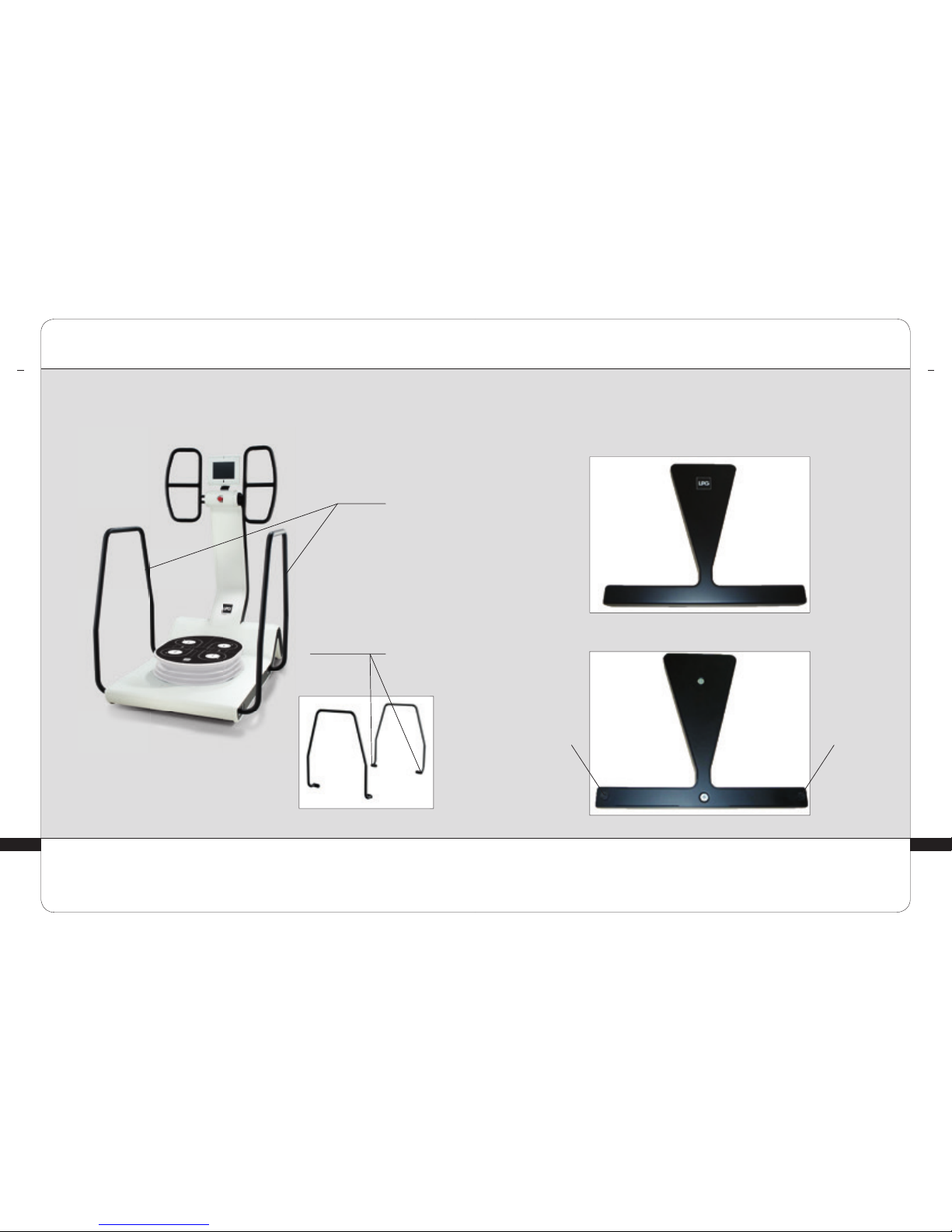
GUARDRAILS
ATTACHMENT MECHANISMS
HUBER 360® EVOLUTION comes with two guardrails attached to the machine.
These guardrails are meant to make the machine easier to use:
Overview
CONTROLS AND ACCESSORIES
2
>
GUARDRAILS
CONTROLS AND ACCESSORIES
2
POSITIONING
PINS
POSITIONING
PINS
>
REPOSITIONING BLOCK
HUBER 360® EVOLUTION comes with a repositioning block that can be positioned on
the platform:
Overview
Underside
Page 10
2120
>
REPOSITIONING BLOCK (CONT.)
POSITIONING THE REPOSITIONING BLOCK
The repositioning block can be positioned on the platform using the positioning
holes shown in the photo below:
POSITIONING HOLE
To position the repositioning block, align the positioning pins on the block with
the positioning holes in the platform.
2
CONTROLS AND ACCESSORIES
3
IMPORTANT SAFETY INFORMATION
>
IMPORTANT SAFETY INFORMATION
The following safety precautions must always be observed when using an electrical
device. Read all instructions before using the device.
DANGER - TO MINIMIZE THE RISK OF ELECTRIC SHOCK:
• Ensure that the circuit breakers are tripped and make sure the voltage is off after
its use and before its cleaning.
• Check that the voltage indicated on the nameplate matches the voltage of the power
outlet.
• High leakage current. ground connection is required before connection to the power
supply. The device must be connected to power circuits that only power this device.
Refer to local regulations.
1 meter
CLEARANCE: provide a clearance of 1 meter all around the device, keeping the
area free of any objects or people.
>
INSTALLATION
Page 11
2322
>
INSTALLATION (CONT.)
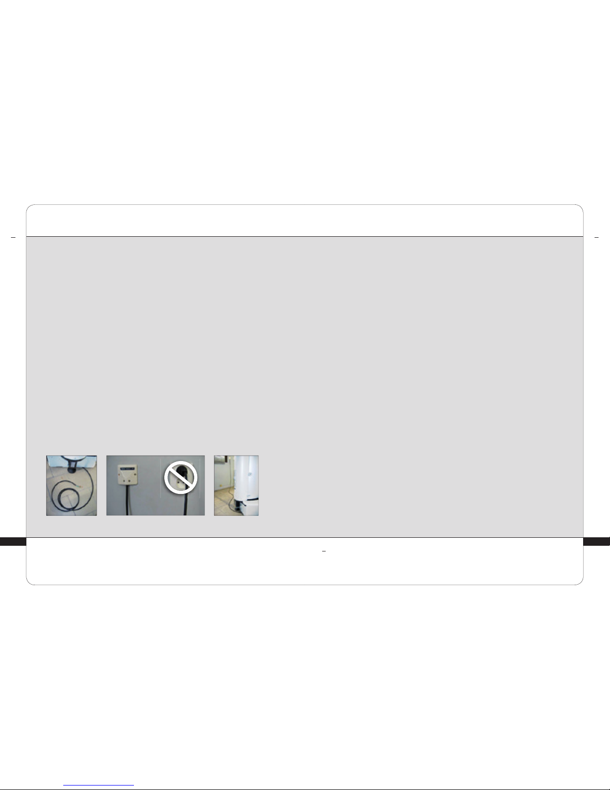
HUBER 360® EVOLUTION
CABLE
FIXED CONNECTION (HUBER 360® EVOLUTION)
AND STANDARD CONNECTION (PROHIBITED)
FIXED
CONNECTION
STANDARD
CONNECTION
INSTALLATION
COMPLETED
The installation of your HUBER 360® EVOLUTION machine must respect the
instructions given in the unpacking notice (to be found in the pocket glued to the box).
HUBER 360
®
EVOLUTION is a non-mobile device and must be connected by an approved
installation expert in accordance with all local/national regulations.
• Before any electrical installation work is undertaken, the electrical current must be
disconnected.
• Ensure that a differential device (detecting the DC and AC components from a frequency
inverter) is installed on the circuit upstream from the machine.This must comply strictly
with all appropriate safety regulations and restrictions.
• Ensure that the circuit-breaker rating is in correct correspondence to HUBER 360
®
EVOLUTION (the upstream circuit breaker must be rated higher than the machine).
Place the wall connection box (with isolating cover) as close to the main electrical supply
as possible for a permanent connection to HUBER 360
®
EVOLUTION. Do not connect with
a standard removable plug and socket.
• Locate the electrical system neutral, ensuring that the voltage on the neutral to ground is
close to 0V.
• Ensure the correct wiring of the phase, earth and neutral in HUBER 360
®
EVOLUTION.
• When the connection is completed, re-connect the electrical current and start
HUBER 360
®
EVOLUTION by activating the on/off circuit breaker.
• Ensure that HUBER 360
®
EVOLUTION is activated and functioning correctly.
• The unit must be connected to a dedicated single power line.
≥
1
Provided power cord information:
Europe H05VVF3G1,50
Japan VCTF3×2,00
USA, Canada, Mexico SJT3×14AWG1,5
WARNING
3
IMPORTANT SAFETY INFORMATION
3
IMPORTANT SAFETY INFORMATION
>
WARNING
• The device should never be left unattended while plugged in.
• Stop the device when not in use for a long period of time or before installing or
removing parts.
• Carefully monitor the device when it is used by, on, or around children or disabled
individuals.
• Never use this device if the power cord
1
or outlet is damaged, if it is not working
properly, if it has been dropped, or if it has been exposed to excessive humidity.
• Return the device to the LPG Systems service center for examination and repair.
• Never use the device if the vents are blocked. Keep openings free of dust and other
contaminants.
• Do not drop or insert any objects into any of the openings. This could damage the
machine.
• Do not use the device on a dirty or uneven floor or in a humid or salty environment, and
do not expose it to bad weather.
• Do not use the device around aerosol (sprays) or oxygen products.
• Never touch the patient and the unprotected connection cables at the same time.
TO MINIMIZE THE RISK OF BURNS, FIRE,
ELECTRIC SHOCK, OR PERSONAL INJURY:
Page 12

2524
>
PRECAUTIONS
• As with any physical training, a medical examination should be performed before using
the equipment.
• The professional should ensure that the settings (platform oscillation speed, amplitude,
activity/rest duration, etc.) are correct for the user’s morphology and physical condition.
• The equipment should be used under careful supervision by a trained professional.
• Users should warm up properly before using the equipment for exercise.
• Users should breathe regularly while exercising.
• Using this equipment with maximum effort is not recommended while the platform is
moving.
• The user should stop immediately if experiencing any discomfort during exercise.
• Do not operate the unit in unsuitable environmental conditions (see technical
specifications).
• When using the articulated stool, the user’s feet should rest on the platform, not on the
base of the articulated stool.
• As its name implies, the emergency stop button should be used only in emergencies.
• The tablet should only be used by a trained professional near the machine.
• This symbol means “High Voltage”:
WARNING : KEEP THESE INSTRUCTI ONS
IMPORTANT SAFETY INFORMATION
3 3
IMPORTANT SAFETY INFORMATION
>
WARNINGS
≥
This machine contains programs meant to guide the user in order for them to obtain the best
possible results that can be expected in their case. This in no way guarantees that the therapy will be
successful. Success varies according to each user’s health, morphology and physiology. It is strictly
prohibited to modify your unit without the authorization of LPG.
WARNING
• The equipment should not be used by anyone with heart, respiratory,
neurological, or rheumatic disease incompatible with physical activity.
• In the case of getting back into shape, maintenance and preventative activity, the
patient should be medically certified to undertake physical activity.
• Due to the risk of possible interference, it is important that the professional
ensure that the patient is not fitted with a personal medical equipment, such as a
pacemaker.
• If this is the case, determine with certainty whether the equipment in question
emits a signal that may interfere with the functioning of the unit.
• The unit must not be used by someone with a medical condition unless
accompanied at all times by a qualified professional certified to the standards of
the country of use.
• In the case of therapy, a diagnostic assessment performed prior to using the unit
provides the following indications and contraindications:
- Joint inflammation
- Acute rheumatism
- Recent trauma
- Musculoskeletal infection
- Fever
- Venous thrombosis
- Acute discopathy
- Neuropsychological problems that prevent an understanding of the instructions
or other serious psychological problems
- Cardiovascular disease or any progressive or chronic condition that
contraindicates exercise
- Severe anatomical deformities
Page 13

2726
IMPORTANT SAFETY INFORMATION
3
>
ELECTROMAGNETIC COMPATIBILTY
For more information on electromagnetic compatibility, refer to “Electromagnetic
Compatibility” in the appendix.
MAINTENANCE
4
>
CLEANING THE DEVICE
You should clean your device as often as possible, not only for hygienic purposes
and attractiveness, but also because cleaning helps maintaining it in good working
order and prolong its life:
• Use a damp sponge to clean the outside of all covers.
• Use wipes impregnated with a bactericidal and fungicidal solution to clean the
handles.
• Use a vacuum cleaner with a narrow attachment to clean the platform and the
inside of the positioning holes.
• For technical problems, please refer to Chapter 5 “Troubleshooting”
>
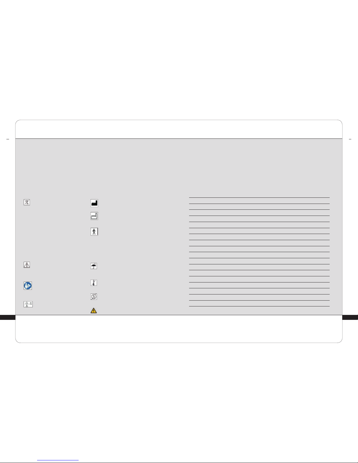
IDENTIFICATION NAMEPLATE
SERIAL NUMBER
VOLTAGE
AND FREQUENCY
The identification plate could be modified. The identification plate apposed on your device is the
approved identification plate.
WARNING
≥
Page 14
2928
The identification nameplate is located on the back of your device.
The nameplate indicates the voltage of the device and the serial number to identify
your device. When contacting LPG Systems customer service for a technical
problem, please provide the serial number of your HUBER 360
®
EVOLUTION.
This serial number gives you the year and month of manufacture of your device.
The letter indicates the year of manufacture: A=2010, B=2011…, E=2014,…
The two digits indicate the production month: 01=January, 02=February,
03=March…
This symbol means that the unit
was sold after August 13, 2006.
In conformity with the 2002/96/EC
directive, it cannot be thrown away with
standard household waste but must be
disposed of in an appropriate sorted
collection. When your device reaches the
end of its useful life, it must be brought
to an appropriate recycling center or
returned to your dealer. By doing so, you
help the environment by contributing to
the conservation of natural resources
and the protection of human health.
This symbol means that some
specific warnings or precautions
associated with this device are not
on the label.
This symbol means carefully read
the accompanying document
before using the device.
This symbol means that the
maximum allowed weight of the
operator of the device is 140 kg.
This symbol indicates the name and
address of the manufacturer.
This symbol indicates manufacturing
year.
This symbol means that your unit
has B parts that come into contact
with the patient. They are electrically
isolated from all other parts of the unit.
These parts are the handlebars, the
platform and the touchscreen interface.
This symbol means store the device
somewhere protected from inclement
weather.
This symbol indicates temperature
limits.
This symbol indicates relative humidity
limits.
This symbol means ”Danger: High
Voltage”
>
IDENTIFICATION NAMEPLATE (CONT.)
MAINTENANCE
4
MAINTENANCE
4
>
POWER CORD
If the power cord of your device is damaged, please contact LPG Systems Customer Service via
the Customer Service Department of your local LPG distributor, for a replacement.
NOTES
Page 15

3130
>
TECHNICAL SPECIFICATIONS
• General features
Dimensions l x w x h . . . . . . . . . . . . . . . . . . . . . . . . . . . . . . . . . . . . . . 180 cm x 105 cm x 210 cm
(133 cm with the guardrails)
Net weight. . . . . . . . . . . . . . . . . . . . . . . . . . . . . . . . . . . . . . . . . . . . . . . . . . . . . . . . . . . . . . . . 285 kg
Maximum weight allowed on the platform . . . . . . . . . . . . . . . . . . . . . . . . . . . . . . . . . . . . . 140 kg
• Electrical features
Voltage. . . . . . . . . . . . . . . . . . . . . . . . . . . . . . . . . . . . . . . . . . . . . . . . . . . . . . . . . . . . . . . . 200 - 240V
Rated frequency . . . . . . . . . . . . . . . . . . . . . . . . . . . . . . . . . . . . . . . . . . . . . . . . . . . . . .50 Hz / 60 Hz
Power consumption . . . . . . . . . . . . . . . . . . . . . . . . . . . Long-time : 750VA - Momentary : 1800VA
• Platform movement
Maximum oscillation frequency . . . . . . . . . . . . . . . . . . . . . . . . . . . . . . . . . . . . . . . . . . . . . 1 tr/sec
Maximum amplitude . . . . . . . . . . . . . . . . . . . . . . . . . . . . . . . . . . . . . . . . . . . . . . . . . . . . . . . . . . 10°
• Force measurement
Handle measurement scale. . . . . . . . . . . . . . . . . . . . . . . . . . . . . . . . . . . . . . . . . . . . . . . .0 to 85 kg
• Weight measurement
Measurement range. . . . . . . . . . . . . . . . . . . . . . . . . . . . . . . . . . . . . . . . . . . . . . . . . . . . .0 to 165 kg
• User replaceable batteries
Heart rate monitor . . . . . . . . . . . . . . . . . . . . . . . . . . . . . . . . . . . . . . . . . . . . . . . . .1 pile 3V CR2025
• Surrounding environment restrictions
Operating temperature . . . . . . . . . . . . . . . . . . . . . . . . . . . . . . . . . . . . . . . . . . . . .+ 10°C to + 30°C
Storage temperature . . . . . . . . . . . . . . . . . . . . . . . . . . . . . . . . . . . . . . . . . . . . . . . - 20°C to + 70°C
Ambient relative humidity . . . . . . . . . . . . . . . . . . . . . . . . . . . . . . 30 to 75% without condensation
Atmospheric pressure . . . . . . . . . . . . . . . . . . . . . . . . . . . . . . .no significant influence for operation
Max altitude . . . . . . . . . . . . . . . . . . . . . . . . . . . . . . . . . . . . . . . . . . . . . . . . . . . . . . . . . . . . . .2500 m
• Thermal caracteristics
Max touch screen temperature. . . . . . . . . . . . . . . . . . . . . . . . . . . . . . . . . . . . . . . . . . . . . . . 42.7°C
>
TROUBLESHOOTING
If your unit is not working properly, please run through the following checklist
before calling LPG Systems Customer Service:
• Is the unit properly connected to a power outlet?
• Is the power outlet live?
• Is the power switch in the ON position?
• Is the emergency stop button pressed? If so, turn off the power, release the
emergency stop button, and then restart the machine.
• For the symptoms listed below, stop the machine and wait 60 seconds before
restarting:
- Error message displayed on the screen;
- Screen not working;
- Excessive weight applied to the platform during exercise;
- Sensor defect.
• Once these checks have been completed and if the problem persists, please
contact LPG Systems Customer Service or the nearest authorized dealer,
indicating the model of your unit and its serial number.
5
TROUBLESHOOTING
LPG Systems Customer Service
+33 (0)4 75 78 69 89
6
TECHNICAL SPECIFICATIONS
Page 16

3332
Device designed for uninterrupted use.
HUBER 360® EVOLUTION is marked as a medical device under appendix
II of the 93/42/EC directive (consolidated version including the 2007/47/EC
Directive).
TECHNICAL SPECIFICATIONS
>
GENERAL WARRANTY CONDITIONS
You have recently acquired an appliance
distributed by LPG Systems or an LPG Systems
approved distributor. It is the purchaser/
user’s responsibility to find out from the local
authorities the conditions and professional
qualifications required before using the
appliance.
The purchase of this equipment implies the
legal acceptance by the purchaser/ professional
user of these general warranty conditions. If
the appliance was sold to you by an approved
LPG Systems distributor, the purchaser/
user should refer to the supplier’s warranty
conditions. These may in no way increase the
undertakings made by LPG in these present
warranty conditions.
The warranty can only be implemented and
is only valid if the warranty slip has been
duly filled out and returned to LPG Systems
within two weeks of delivery, irrespective of the
country. Warranty slips that are only partially
completed will be rejected.
The appliance is guaranteed against
manufacturing flaws and defects in the raw
materials.
The warranty extends for the shorter
of the following two periods: one (1) year
OR two thousand (2000) hours of use from
the invoice date. During this period, LPG
Systems undertakes to exchange or repair
free of charge, as quickly as possible, any
part that LPG Systems acknowledges as
defective, however LPG Systems does not
undertake to replace the entire appliance.
Traveling and living expenses for our
technicians and transportation costs of the
appliance or parts to and from the aftersales
service workshop are not covered by this
warranty.
Replacements and repairs performed within
this warranty, with or without immobilization
of the equipment, shall not have the effect of
extending the warranty period. Replaced parts
become the property of LPG Systems or the
approved distributor.
No compensation shall be paid for loss of use.
Subject to other conditions hereafter, warranty
shall apply if the purchaser/professional user
has allowed LPG to proceed to necessary repair
works.
6
>
TECHNICAL SPECIFICATIONS (CONT.)
WARRANTY
7
Page 17

3534
WARRANTY
• Damage occurring during transportation.
Transportation of this equipment and/or
spare parts is at the recipient’s own risk.
Before taking delivery, it is the recipient’s
responsibility to verify the state of the goods
and to make a claim against the transport
company in the manner usual in the delivery
country.
• Non-observance of the installation and
operating instructions, failure to carry
out maintenance and/or negligence in
maintaining the appliance, connection to a
faulty electricity supply or a non-earthed
electricity supply or a power supply whose
voltage is different to the one indicated on
the appliance.
• If an appliance is sold before the end of the
warranty period, the warranty is transferred
to the purchaser for the remaining warranty
period, on the condition that:
I The original invoice is provided.
II That the initial vendor is informed of the sale.
• Modification, mounting of accessories or
dismantling of the equipment.
• Any operation and/or intervention not
specified in the LPG Systems Operator’s
Manual and performed on the equipment
by the purchaser/user and/or any party not
approved by LPG Systems.
• Use of consumables, spare parts,
inappropriate components or parts not
supplied by LPG Systems.
• Normal wear and tear of any of the
equipment’s parts resulting from
normal usage.
• Damages or default resulting of accidental
events (falls, impacts...)
Damages or default resulting of natural
disasters (lightening, water damages...),
fire, negligence or abuses.
Warranty exclusion:
7
WARRANTY
WARRANTY
7
>
GENERAL WARRANTY CONDITIONS
>
WARRANTY ACTIVATION
YOU CAN ACTIVATE YOUR WARRANTY ONLINE AT:
http://warranty.lpgsystems.com
Failure to comply with the general warranty conditions during the warranty period and after
its expiry may constitute an exonerating cause of liability of LPG Systems in case of damage
attributable to the delivered products.
The purchaser/user is responsible for the use of the device and will assume full responsibility
for any damages, including damages caused to third parties, resulting from the failure to
observe the instructions for use of the device and / or resulting from an improper use.
Under no circumstances LPG SYSTEMS will be held liable for any intangible or indirect
damages, including any commercial or financial loss, loss of profit, loss of earnings, and
damage to the brand image.
LPG SYSTEMS’ liability, for all causes (with the exception of personal injury) is limited to the
amount of the defective device’s price.
Page 18
3736
>
OR FILL IN THE FORM AND RETURN TO LPG SYSTEMS
®
7
WARRANTYWARRANTY
Name: . . . . . . . . . . . . . . . . . . . . . . . . . . . . . . . . . . . . . . . . . . . . . . . . . . . . . . . . . . . . . . . . . . . . . . .
Address: . . . . . . . . . . . . . . . . . . . . . . . . . . . . . . . . . . . . . . . . . . . . . . . . . . . . . . . . . . . . . . . . . . . . .
Email: . . . . . . . . . . . . . . . . . . . . . . . . . . . . . . . . . . . . . . . . . . . . . . . . . . . . . . . . . . . . . . . . . . . . . . .
HUBER 360® EVOLUTION serial number: . . . . . . . . . . . . . . . . . . . . . . . . . . . . . . . . . . . . . . . . .
Date: . . . . . . . . . . . . . . . . . . . . . . . . . . . . . . . . . . . . . . . . . . . . . . . . . . . . . . . . . . . . . . . . . . . . . . . .
Through the form above, LPG SYSTEMS, which is the data controller, operates a processing
of your personal data, based on the sales agreement of your HUBER 360® EVOLUTION
device, in order to manage the guarantees that apply to it. LPG SYSTEMS only stores your
data for the time required by the operations for which it was collected and in compliance
with the regulations in force.
In accordance with the applicable regulations, you have the right to access, rectify and
delete your personal data, a right of limitation or opposition to the treatment for legitimate
reasons, a right of define general and specific guidelines on how you intend to exercise
your rights after your death, the right to portability of your data, and the right to lodge a
complaint with a supervisory authority .
You can exercise your rights by email at dataprivacy@lpgsystems.com or by mail at: LPG
SYSTEMS, Customer Service Department, Technoparc de la Plaine, 30 rue Dr Abel, CS
90035 - 26000 VALENCE (FRANCE), with a photocopy of an identity document bearing your
signature.
APPENDIX: ELECTROMAGNETIC COMPATIBILITY
8
>
APPENDIX: ELECTROMAGNETIC COMPATIBILITY
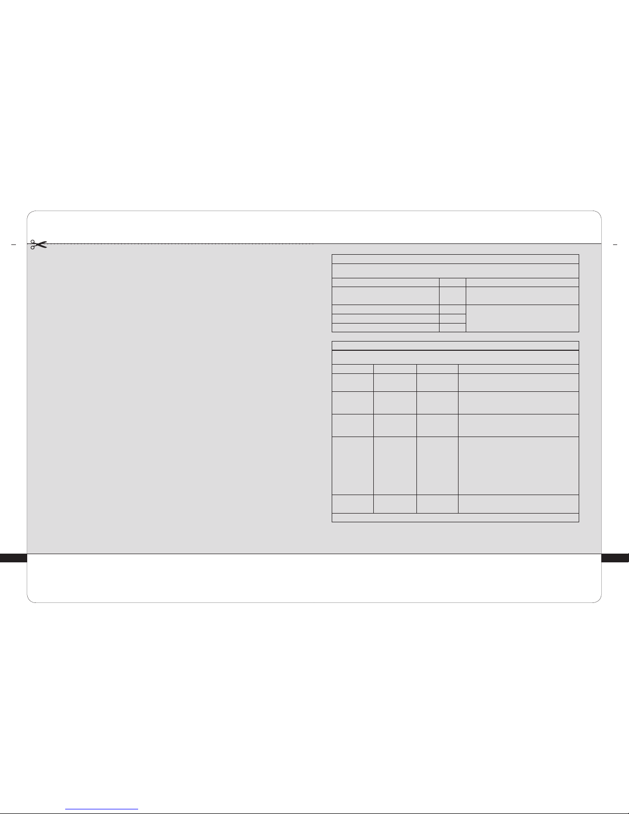
TABLE 1: DIRECTIVES AND MANUFACTURER DECLARATION – ELECTROMAGNETIC EMISSIONS
HUBER 360® EVOLUTION is intended for use in the electromagnetic environment specied below. HUBER 360® EVOLUTION customer or patient
should ensure that it is used in such an environment.
Emissions test Conformity Electromagnetic Environment - Directives
RF emissions CISPR 11 Group 1 HUBER 360® EVOLUTION uses RF energy only for its internal
functions. Therefore, its RF emissions are very low and unlikely
to cause interference in nearby electronic devices.
RF emissions CISPR 11 Class B HUBER 360® EVOLUTION may be used in all establishments,
including domestic sites and sites that are directly connected
to the low voltage public power grid, which supplies domestic
buildings.
Harmonic emissions IEC 61000-3-2 Class A
Voltage uctuations and icker IEC 61000-3-3 Conforms
TABLE 2: DIRECTIVES AND MANUFACTURER DECLARATION – ELECTROMAGNETIC IMMUNITY – EMISSIONS TESTS
HUBER 360® EVOLUTION is intended for use in the electromagnetic environment specied below. HUBER 360® EVOLUTION customer or patient
should ensure that it is used in such an environment.
Emissions test Conformity Conformity Electromagnetic Environment - Directives
Electrostatic
discharge (ESD)
IEC 61000-4-2
± 6 kV on contact
± 8 kV in the air
± 6 kV on contact
± 8 kV in the air
Flooring should be made of wood, concrete, or ceramic tile.
If the oor is covered with synthetic material, relative humidity
should be at least 30%.
Fast transient/burst
IEC 61000-4-4
± 2 kV for electrical
power lines
± 1 kV for input/output
lines
± 2 kV for electrical
power lines
± 1 kV for input/
output lines
The quality of the electrical power network should be equivalent
to that of a typical commercial or hospital environment.
Surge
IEC 61000-4-5
± 1 kV between
phases
± 2 kV between phase
and earth
± 1 kV between
phases
± 2 kV between phase
and earth
The quality of the electrical power network should be equivalent to
that of a typical commercial or hospital environment.
Voltage dips, short
interruptions, and
voltage variations
IEC 61000-4-11
<5% UT
(>95% voltage dip)
during 0.5 cycle
40% UT
(60% UT voltage dip)
during 5 cycles
70% UT
(30 % UT voltage dip)
during 25 cycles
<5% UT
(>95% voltage dip)
during 5s
<5% UT
(>95% voltage dip)
during 0.5 cycle
40 % UT
(60% UT voltage dip)
during 5 cycles
70% UT
(30 % UT voltage dip)
during 25 cycles
<5% UT
(>95% voltage dip)
during 5s
The quality of the electrical power network should be equivalent to
that of a typical commercial or hospital environment.
If HUBER 360® EVOLUTION patient requires operation to continue
during power outages, HUBER 360® EVOLUTION should be powered
through an uninterruptible power supply or a battery.
Power frequency
magnetic eld
IEC 61000-4-8
3 A/m 3 A/m Power frequency magnetic elds should have levels that are
characteristic of a typical hospital or commercial environment.
NOTE: UT is the AC voltage prior to the application of the test level.
Page 19
1571 - Ed 10/18 - GB - © LPG Systems 2018 - LPG Systems SAS au capital de 2 124 950 euros- Siren RCS 335.183.836 Romans - Any reproduction – even in part – is strictly prohibited. Non-binding photos.
HEADQUARTERS : LPG SYSTEMS
TECHNOPARC DE LA PLAINE
30, RUE DU DR. ABEL - CS 90035 - 26902 VALENCE CEDEX 09 - FRANCE
TEL.: +33 (0)4 75 78 69 00 - FAX: +33 (0)4 75 42 80 85
INTERNATIONAL/MARKETING
2753, ROUTE DES DOLINES - BP 243
06905 SOPHIA-ANTIPOLIS CEDEX - FRANCE
TEL.: +33 (0)4 92 38 39 00 - FAX: +33 (0)4 92 96 09 65
38
>
APPENDIX: ELECTROMAGNETIC COMPATIBILITY
TABLE 3: DIRECTIVES AND MANUFACTURER DECLARATION – ELECTROMAGNETIC IMMUNITY – IMMUNITY TESTS
HUBER 360
®
EVOLUTION is intended for use in the electromagnetic environment speci ed below. The HUBER 360® EVOLUTION customer or
patient should ensure that it is used in such an environment.
Immunity
Test
Test level
according to IEC
60601
Conformity
level
Electromagnetic environment - directives
Conducted RF
disturbances
IEC 61000-4-6
3 Veff
150 kHz to 80 MHz
3V
Portable and mobile RF communications devices should not be used closer to any part
of HUBER 360
®
EVOLUTION, including its cables, than the recommended separation
distance, calculated from the applicable equation on transmitter frequency.
Recommended separation distance:
d = 1.2√P
d = 1.2√P 80 MHz at 800MHz
d = 2.3√P 800 MHz at 2.5 GHz
where P is the transmitter’s maximum power output in watts (W), according to the
transmitter’s manufacturer, and d is the recommended separation distance in meters (m).
The eld strength for xed RF transmitters, as determined by an electromagnetic survey
at site a, should be less than the conformity level for each range of frequencies b.
Interference may be produced near the device marked with the following symbol:
Perturbations
RF rayonnées
CEI 61000-4-3
3 V/m
De 80 MHz
to 2,5 GHz
3 V/m
NOTE 1: At 80 MHz and 800 MHz, the highest frequency range applies. NOTE 2: These directives may not apply in all situations.
Electromagnetic propagation is affected by absorption and by re ections of structures, objects, and people.
a
The eld strength of xed transmitters, such as radio/telephone (cellular/wireless) base stations and land mobile radios, amateur radios,
AM and FM radio broadcasting, and TV broadcasting cannot be theoretically predicted with accuracy. To measure the electromagnetic
environment due to xed RF transmitters, consider performing an electromagnetic survey of the site. If the eld strength, measured where
HUBER 360® EVOLUTION is used, exceeds the applicable RF conformity level above, watch HUBER 360® EVOLUTION to ensure that it is
operating as normal. If there is any abnormal performance, additional measures may be necessary, such as reorienting or repositioning
HUBER 360® EVOLUTION.
b
For the frequency range of 150 kHz to 80 MHz, eld strength should be less than 3 V/m.
TABLE 4: RECOMMENDED SEPARATION DISTANCES BETWEEN PORTABLE AND MOBILE RF COMMUNICATION DEVICES
AND HUBER 360® EVOLUTION
HUBER 360
®
EVOLUTION is intended for use in an electromagnetic environment in which radiated RF disturbances are controlled. The HUBER
360® EVOLUTION patient or customer can prevent electromagnetic interference by maintaining a minimal distance between the portable or
mobile RF communications device (transmitter) and HUBER 360® EVOLUTION, as recommended below, based on the maximum transmission
power of the communication device.
Maximum rated
output of the
transmitter W
Separation distance according to the transmitter frequency m
d=1,2√P d=1,2√P d = 2,3√P
0,01 0,12 0,12 0,23
0,1 0,38 0,38 0,73
1 1,2 1,2 2,3
10 3,8 3,8 7,3
100 12 12 23
For transmitters whose maximum rated output is not shown above, the recommended separation distance d in meters (m) can be estimated using
the applicable equation for the transmitter frequency, where P is the transmitter’s maximum output in watts (W), according to its manufacturer.
NOTE 1: At 80 MHz and 800 MHz, the separation distance for the highest frequency range applies.
NOTE 2: These directives may not apply in all situations.
Electromagnetic propagation is affected by absorption and by re ections of structures, objects, and people.
APPENDIX: ELECTROMAGNETIC COMPATIBILITY
8
 Loading...