

LP HAL1200 Atlantic, HAL600 Atlantic User Manual
USER'S MANUAL
1200W AUTOMATIC LINEAR AMPLIFIER
Model: HAL1200 Atlantic
1

A - Introduction
Thank you for purchasing the HAL 1200 Atlantic.
(Automatic Transistorized Linear Amplifier No Tune Inside Computerized).
This compact and lightweight desktop HF linear power amplifier has a
maximum input power of 2.4 KW.
Our solid-state broadband power amp technology makes it the smallest and
lightest in the industry.
Typical output power is 1200W PEP/SSB with the drive power of 25-35 W.
The built-in band decoder will allow you forget about the band setting, without
any data connection to the transmitter, or when the amplifier is connected to
the modern radio through these cables band data as Yaesu BAND DATA,
Icom CI-V, Kenwood RS-232C or IF-232, Elecraft BAND OUT.
B - Cautions
B-1 Unpack the amplifier, check the fan guard at the rear panel Fan to see if
there is any damage caused by the physical shock during the transportation.
Fan blades must be free to rotate when powered.
The amplifier is cooled by forced airflow. Several inches of clearance on the
top and the rear wall are necessary to allow for smooth air intake into the fan.
B-2 Keep the amplifier out of direct sunlight, in a cool dry environment.
B-3 Internal high voltages, (AC, DC and RF), are present at all times, ON
AIR or OFF. Internal access should be limited to avoid injury.
B-4 Turn off the AC main power immediately upon any unusual sounds,
sights or odors. Check readings the display for Warning messages, the fuses
and all cable connections around the amplifier. Please notify the dealer or the
factory of any problems.
B-5 For your safety, do not operate the amplifier without adequate
grounding. A proper ground connection will result in peak performance and
stability, in addition to reduced RF strays or noises.
B-6 To eliminate the RF interference to such home appliances as TV, FM
radio, telephone sets, etc., it is recommended that clamp-on ferrite cores be
inserted at both ends of the remote control cable, coaxial jumper cable, and
antenna cables, as needed. Also, a common mode AC line filter (near the AC
outlet), and in-line low pass filters on the antenna coaxial cable, (as
necessary), are recommended.
2

B-7 The amplifier has fast acting sophisticated protection circuits controlled
by the latest microprocessor technology. Please note, however, any such
actions that cause the same fault to occur repeatedly, will lead to failure of the
valuable final power MOSFET transistors.
B-8 Before checking into the amplifier, always disconnect the mains power
supply, with the power disconnected, press the power switch to "POWER" to
ON, be sure to wait a minute to allow the high voltage discharge DC , return
the switch to OFF.
The internal potentiometers for RF power detector, protection circuits,
MOSFET bias voltage circuit, etc., are precisely adjusted at the factory, and
should not be altered. Doing so, would require readjustment with precision
measuring instruments.
B-9 The primary power supply is for AC from 100 to 260 V operation. Be
sure to verify your AC line voltage before you plug the AC power cord into the
outlet.
B-10 Before powering on the amplifier, be sure to connect a dummy load
(50 ohms, 1500 W min.) or a well-adjusted antenna to the output terminal.
Operating without any load will cause extreme stress to the RF power
MOSFET’s, although protection circuits should work under critical conditions.
B-11 Required drive power is slightly less than 30 W to obtain the full 1200 W
output. Do not attempt to operate with excessive drive from a high power
transceiver. Transmitting high drive RF (over 70 W) into the amplifier will void
the warranty.
B-12 Keep the copper/aluminum heat sink and air openings free from dust
and blockages. Periodic cleaning will prevent degraded cooling efficiency.
B-13 For long continuous operation in RTTY/FM modes, it is recommended
you reduce the RF drive levels by 20% to 30% lower output than CW/SSB
modes.
B-14 To prevent damage to the precision electronic components, avoid
extreme physical shock to the amplifier. If factory service is required, the
amplifier must be shipped using the original box and packaging materials.
3

C - Features
C-1 Our solid-state broadband design engineers worked to make the
HAL 1200 Atlantic, the lightest and most compact 1200 W HF amplifier in the
industry.
C-2 The amplifier is equipped with a newly developed band decoder.
The amplifier’s decoder whit the microprocessor, on detecting RF input,
changes bands automatically without any external connection, or as the data
signal is received from the connection of the associated HF transceiver’s
frequency bands.
C-3 The amplifier’s main PA section includes 4 high power MOSFET
SD2933 by ST Microelectronics, resulting in 1200 W PEP (SSB max.). The
amplifier’s broadband characteristics require no further tuning once the
operating band is selected.
C-4 The amplifier has no output ALC, because by the microprocessor,
controls the input attenuation, to keep the linear region between 20 to 45 W of
drive.
C-5 To ensure a clean RF emission, were used filters LPF of the fifth order
Cauer.
C-6 With the unique duct structure design and the powerfull blower fan, the
copper/aluminium heat sink block for RF PA module (and other components),
are effectively cooled. The fan’s quiet operation allows for even the weakest
DX signals to be heard.
C-7 The amp utilizes an advanced 16 bit MPU (microprocessor) to run the
various high speed protection circuits such as OverDrive, High antenna SWR,
OverHeating PA , in the event of erroneus Band Change, etc.
C-8 A bright, backlit LCD display, in graphical and numerical displays the
input power, output power and reflected power simultaneously, as well as
various status data and warning messages.
4

D - Specifications
Frequency : 1.8 ~ 54 MHz
all amateur bands including WARC bands
Automatic Band Change
(only PTT/TXGND Signal), or
with dedicated connection for the most common
Transceivers Yaesu, Kenwood, ICOM, Elecraft .
Mode : SSB, CW, RTTY
RF Drive : 20 ~ 45 W (30W typ.)
(automatic selection: NO ALC)
Output Power : 1200W PEP / 1000W CW (typ.) - HF
600W PEP / 500W CW (typ.) - 6 meters Band
Drain Voltage : 50 V
Drain Current : 40 A max.
Input Impedance : 50Ω (unbalanced)
Output Impedance : 50Ω (unbalanced)
Final Transistor : SD2933 x 4 (MOSFET by ST Microelectronics)
Harmonics : -50 dB (<)
IMD3 : -34 dB (typ.)
Output Filters : LPF CAUER of 5th order
(160m, 80m, 40m, 30/20m, 17/15m, 12/10m, 6m)
Cooling Method : Forced Air (Fan)
MPU : HITACHI/Renesas 16bit
DISPLAY : LCD FSTN 20x4 Backlight;
at Real Time:
- Band
- Type of Automatic Band Change
- Temperature of Power Section
- Status (Ready, StandBy, On Air,
Protect, Warning, .......)
- Warning of Protection
- Announcement for Attenuator Insertion
- Input Power (Graphic/Numeric)
- Output Power (Graphic/Numeric)
- Reflected Power (Graphic/Numeric)
at StandBy, Menu:
- Start (StandBy/Ready)
- AutoBand (Automatic/CAT)
- Temperature (Celsius/Fahrenheit)
5

PROTECTIONS: - Over Drive
- Output Power Limiter
- High SWR (SWR > 2:1)
- Over Temperature
- Fault of PA Fuses
- In the event of erroneus Band Change
Input/Output Connectors: UHF SO-239 Teflon
AC Power : AC 100 ~ 260 V / 16 ~ 10 A max.
Dimension : 261 x 334 x 153 mm (W x D x H)
Weight : Approx. 9 kg.
Accessories : AC Power Cord x 1
: Spare Fuse 10 A x 1 (for AC 230V line)
: Spare Fuse 16 A x 2 (for PA)
Only for KIT version : Fuse Holder x 1 with Fuse 10A x 1 (for AC 230V line)
6
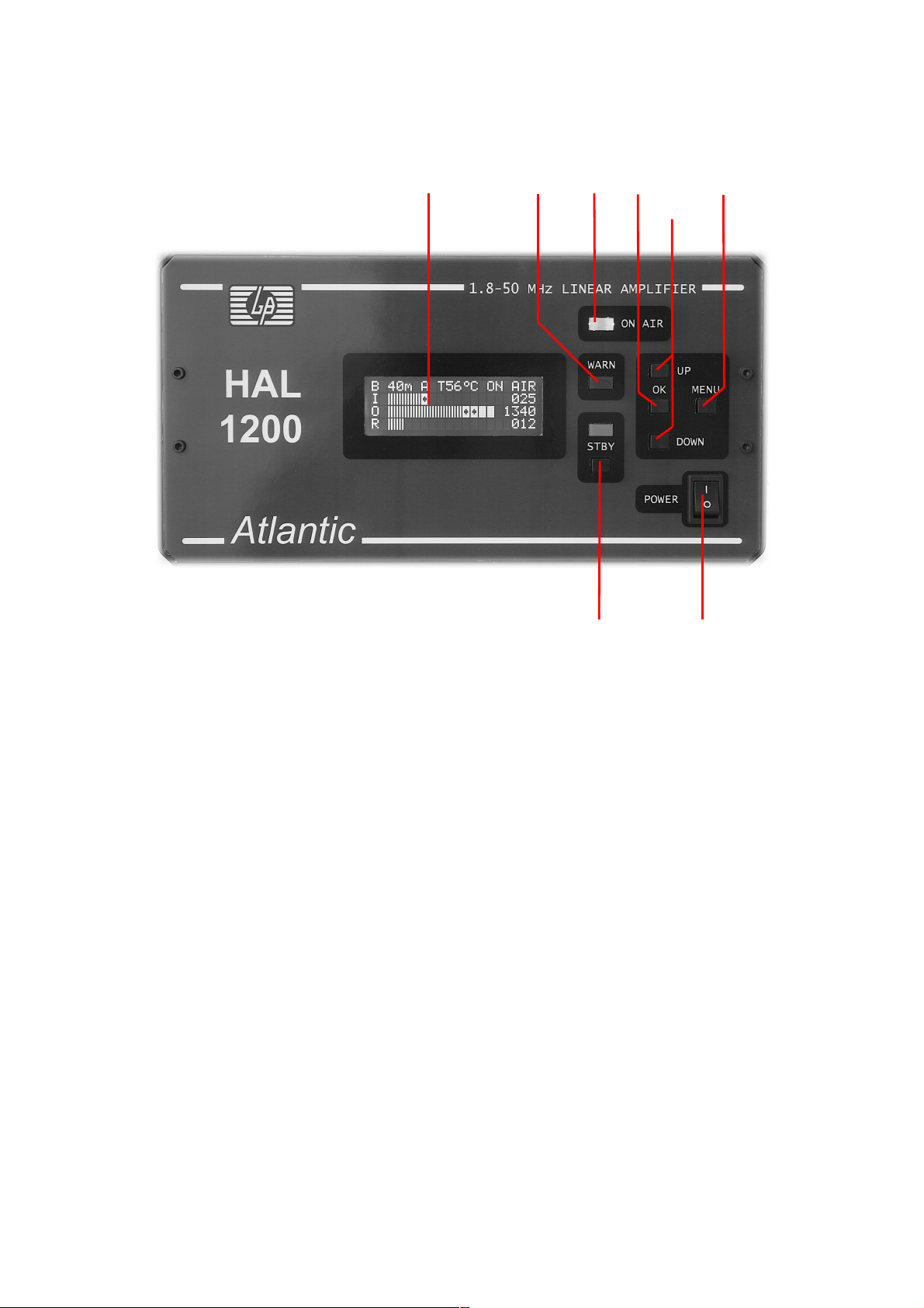
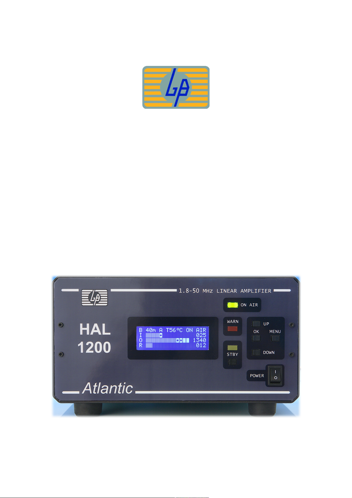
E - Front Panel Description
③ ④ ⑤ ⑥ ⑦
⑧
② ①
① POWER Main power switch to turn AC power ON (I) and OFF (O).
Display lights when turned on.
② STBY STAND-BY/OPERATE key and annunciator Yellow LED.
At STAND-BY mode, the Yellow LED is ON, RF signal pass through.
At OPERATE, ( READY) the amplifier is ready to go into ON AIR (TX) mode,
the yellow LED is OFF.
③ BACKLIGHT LCD DISPLAY.
④ WARN Warning Red LED annunciator.
Blinking for Warning, ON at PROTECTED Status (amp. Stopped).
⑤ ON AIR Green LED annunciator.
Lights when the amplifier is in transmit (TX) mode.
7
 Loading...