

Page 1

Item: __________________________
Quantity: ______________________
Tray Stand
Project: ________________________
Date: __________________________
MODELS
❑ 28-RTS side station
❑ 36-RTS side station
❑ 28-RTE end station
❑ 36-RTE end station
36-RTE Tray Stand shown.
Top:
❑ 36” Counter Top Height
❑ Other Height (specify ___________)
❑ Top Extensions (width ___________)
❑ Top Extensions (length ___________ )
❑ Silverware Wells with inserts
❑ Napkin Pan
Base Options:
❑ Cam Operated Line-up Locks
❑ Custom Color (specify RAL #)
❑ 5” Diameter Casters
❑ Stainless Steel Legs
❑ Other ___________
Other Options:
❑ Theme Package
❑ School Bus
❑ Train
❑ Space Shuttle
❑ Covered Wagon
❑ Circus Train
❑ Other (specify)
Add silverware and napkin
wells to top for space-saving
versatility.
Durable, colorful, molded
fiberglass
East to clean, low maintenance
Labor saving mobility
P.O. Box 795 • Jonesboro, GA 30237
Tel: 770.478.8803 • Fax: 770.471.3715
www.lowtempind.com • colorpoint@lowtempind.com
11
Page 2
Item: _____________________________
Quantity: _________________________
Tray Stand
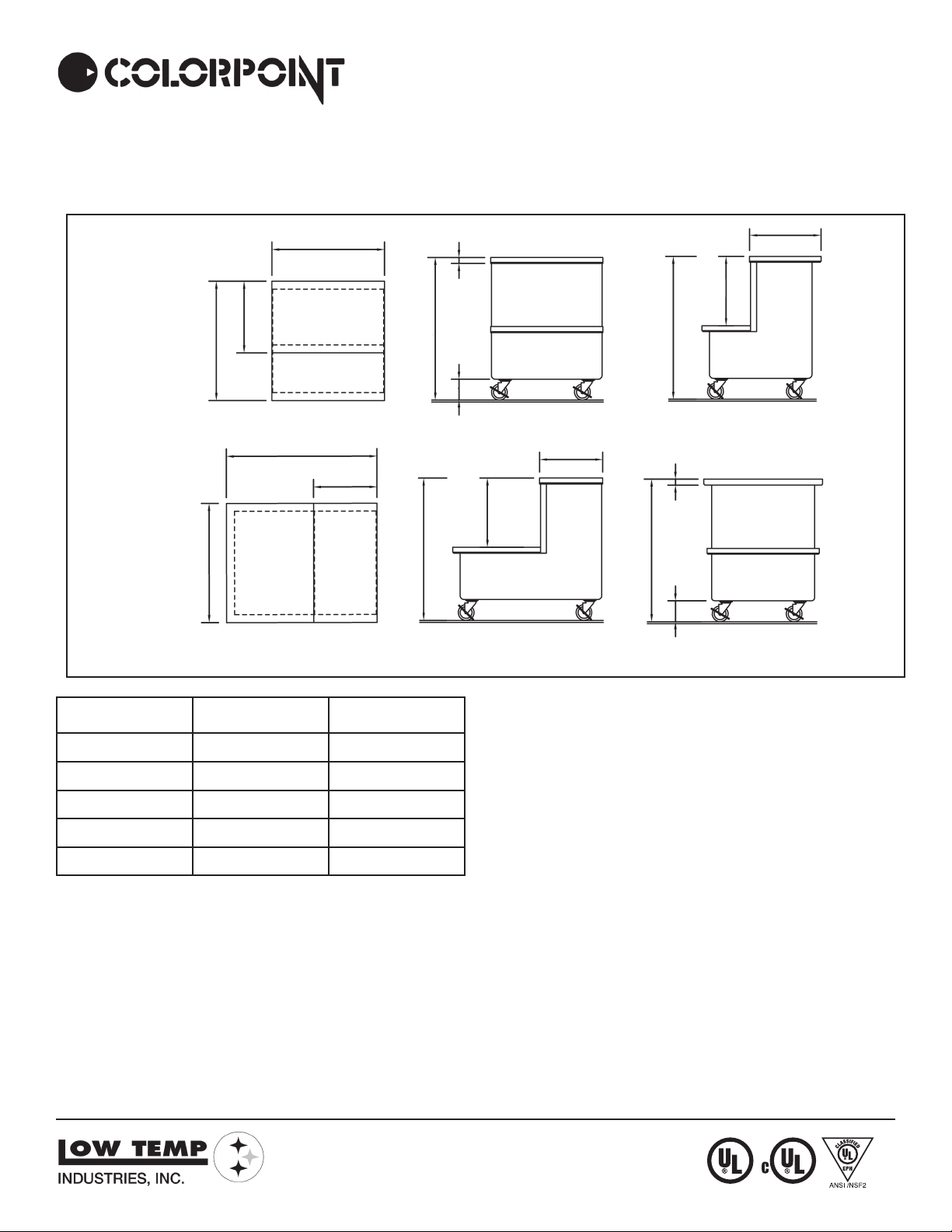
28-RTS/36-RTS
28-RTE/36-RTE
18”
30”
30”
Low Side
L
Low Side
Plan View
L
16”
36”
36”
Project: ___________________________
Date: _____________________________
18”
”
2
/
1
1
”
2
/
1
17
36”
”
4
/
1
5
Side View End View
16”
”
2
/
1
17
”
2
/
1
1
36”
Plan View
APPROX. SHIP
MODEL L WEIGHT
28-RTS 28 3/8” 205 lbs.
36-RTS 36 3/8” 220 lbs.
28-RTE 28 3/8” 205 lbs.
36-RTE 36 3/8” 220 lbs.
TOP: Top and platform to be 30” wide and
fabricated from a minimum of 14 ga. stain
less steel with square turndown on all sides
and corners fully welded, ground and pol
ished. Top to have #4 satin finish and with
all edges having a #7 hi-lite finish.
BODY: Body to be seamless molded fiberglass (F.R.P.) with smooth exterior surfaces
and rounded corners. To be constructed
by a hand lay-up process with four layers
of 1.5 oz continuous strand fiberglass mat,
plus a 24 oz layer of woven roving on the
bottom for added strength. Fiberglass to
be flame retardant per specification ASTM
E-162 having a flame spread of 25 or
less. Body interior to be reinforced at each
end with 4” wide, 12 gauge galvanized
channels welded to form integral “U” frame
for maximum stress relief.
CASTERS: 4” diameter, ball bearing, swivel type casters to be non-marking and with
brakes on all wheels. Casters to be mounted
thru two 12 gauge channels for extra rigid
ity.
P.O. Box 795 • Jonesboro, GA 30237
Tel: 770.478.8803 • Fax: 770.471.3715
www.lowtempind.com • colorpoint@lowtempind.com
”
4
/
1
5
Side View End View
We reserve the right to change specifications and product design without notice. Such revisions do not entitle the buyer to
corresponding changes, improvements, additions or replace
ment for previously purchased equipment.
All equipment to be built in accordance with the Underwriters
Laboratories. Inc. and the National Sanitation Foundation, Inc.
standards and shall bear the Underwriters Laboratories, Inc.
listing label for safety and the Underwriters Laboratories clas
sification label for sanitation.
-
U.L. SanitationClassified to NSF Standards
-
-
05/2006
 Loading...