

Page 1
HDS Gen3
Operator Manual
ENGLISH
lowrance.com
Page 2

Page 3

Preface
Disclaimer
As Navico is continuously improving this product, we retain the
right to make changes to the product at any time which may not be
reflected in this version of the manual. Please contact your nearest
distributor if you require any further assistance.
It is the owner’s sole responsibility to install and use the equipment
in a manner that will not cause accidents, personal injury or
property damage. The user of this product is solely responsible for
observing safe boating practices.
NAVICO HOLDING AS AND ITS SUBSIDIARIES, BRANCHES AND
AFFILIATES DISCLAIM ALL LIABILITY FOR ANY USE OF THIS PRODUCT
IN A WAY THAT MAY CAUSE ACCIDENTS, DAMAGE OR THAT MAY
VIOLATE THE LAW.
Governing Language: This statement, any instruction manuals, user
guides and other information relating to the product
(Documentation) may be translated to, or has been translated from,
another language (Translation). In the event of any conflict between
any Translation of the Documentation, the English language version
of the Documentation will be the official version of the
Documentation.
This manual represents the product as at the time of printing.
Navico Holding AS and its subsidiaries, branches and affiliates
reserve the right to make changes to specifications without notice.
Trademarks
Lowrance® and Navico® are registered trademarks of Navico.
Fishing Hot Spots® is a registered trademark of Fishing Hot Spots Inc.
Copyright© 2012 Fishing Hot Spots.
Navionics® is a registered trademark of Navionics, Inc.
NMEA 2000® is a registered trademark of the National Marine
Electronics Association.
SiriusXM® is a registered trademark of Sirius XM Radio Inc.
FUSION-LinkTM Marine Entertainment StandardTM is a registered
trademark of FUSION Electronics Ltd.
Preface | HDS Gen3 Operator Manual
3
Page 4

The terms HDMI and HDMI High-Definition Multimedia Interface,
and the HDMI Logo are trademarks or registered trademarks of
HDMI Licensing LLC in the United States and other countries.
SDTM and microSDTM are trademarks or registered trademarks of
SD-3C, LLC in the United States, other countries or both.
Additional mapping data: Copyright© 2012 NSI, Inc.: Copyright©
2012 by Richardson’s Maptech.
Navico product references
This manual refers to the following Navico products:
• Broadband Radar™ (Broadband Radar)
• DownScan Imaging™ (DownScan)
• DownScan Overlay™ (Overlay)
• GoFree™ (GoFree)
• SmartSteer™ (SmartSteer)
• SonicHub® (SonicHub)
• StructureMap™ (StructureMap)
• StructureScan® (StructureScan)
• StructureScan® HD (StructureScan HD)
Copyright
Copyright © 2014 Navico Holding AS.
Warranty
The warranty card is supplied as a separate document.
In case of any queries, refer to the brand website of your display or
system: lowrance.com.
Regulatory statements
This equipment is intended for use in international waters as well as
coastal sea areas administered by countries of the E.U. and E.E.A.
The HDS Gen3 complies with:
• CE under R&TTE directive 1999/5/EC
• The requirements of level 2 devices of the
Radiocommunications (Electromagnetic Compatibility)
standard 2008
The relevant Declaration of conformity is available in the HDS Gen3
section on the following website: lowrance.com.
4
Preface | HDS Gen3 Operator Manual
Page 5
About this manual
The manual assumes that the user has basic knowledge of
navigation, nautical terminology and practices.
Important text that requires special attention from the reader is
emphasized as follows:
Ú
Note: Used to draw the reader’s attention to a comment or
some important information.
Warning: Used when it is necessary to warn
personnel that they should proceed carefully to
prevent risk of injury and/or damage to equipment/
personnel.
Manual version
This manual is written for the HDS Gen3 software version 1.0. The
manual is continuously updated to match new software releases.
The latest available manual version can be downloaded from
lowrance.com.
Preface | HDS Gen3 Operator Manual
5
Page 6
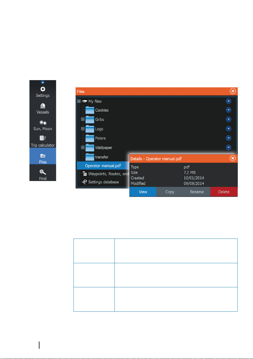
Viewing the manual on the screen
The pdf viewer included in the HDS Gen3 makes it possible to read
the manuals and other pdf files on the screen. Manuals can be
downloaded from lowrance.com.
The manuals can be read from an inserted microSD card or copied
to the unit’s internal memory.
Use the menu options or the keys and on-screen buttons to
maneuver in the pdf file as described below:
Search, Goto
page, Page Up
and Down
Scroll pages Touch operation: Drag finger on the screen in
Panning on the
page
6
Preface | HDS Gen3 Operator Manual
Select the relevant panel button.
any direction.
Key operation: Use the cursor keys.
Touch operation: Drag finger on the screen in
any direction.
Key operation: Use the cursor keys.
Page 7
Zoom In/Out Select the relevant panel button.
Touch operation: Use pinch or spread gestures.
Key operation: Use the + and - keys.
Exit the pdf
viewer
Touch operation: Select the X in the upper right
corner of the panel.
Key operation: Press the X key.
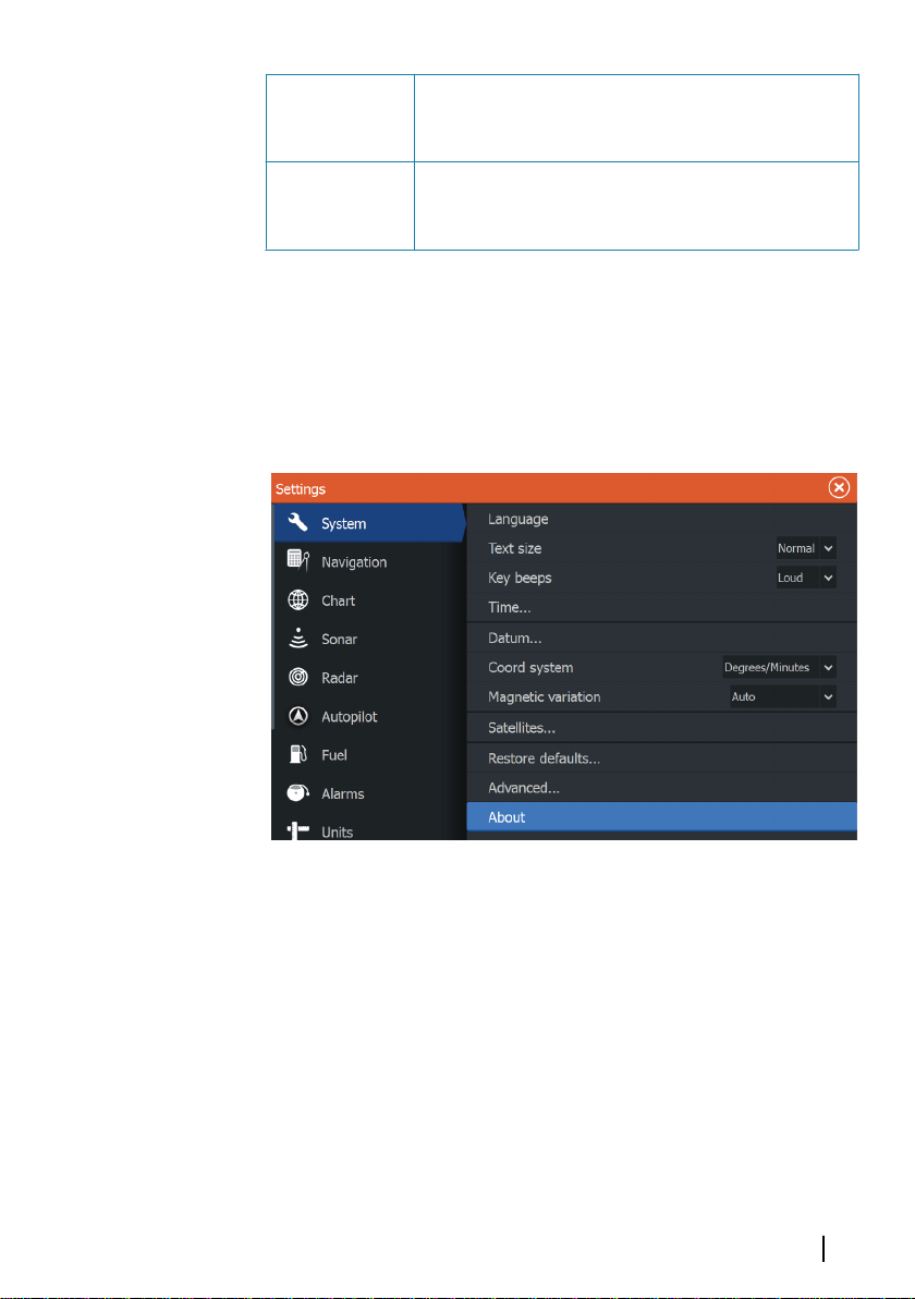
The Software version
The software version currently on this unit can be found in the
About dialog. The About dialog is available in the System Settings.
For more information, refer to "About" on page 142. For upgrading
your software, refer to "Software upgrades" on page 150.
Preface | HDS Gen3 Operator Manual
7
Page 8

8
Preface | HDS Gen3 Operator Manual
Page 9

Contents
15 Introduction
Operating the system
15
16
The front panel and keys
The Home page
18
19 Application pages
21 Integration of 3rd party devices
23 Basic operation
23 Systems Controls dialog
23 Turning the system on and off
24 Display illumination
24 Locking the touchscreen
25 Using menus and dialogs
26 Selecting pages and panels
26 Using the cursor on the panel
28 Creating a Man Overboard waypoint
29 Screen capture
30 Customizing your system
30 Customizing the Home page wallpaper
30 Adjusting panel size
31 Data Overlay
32 Adding new favorite pages
32 Edit favorite pages
33 Charts
33 The Chart panel
34 Chart data
34 Showing dual chart types
35 Vessel symbol
35 Chart scale
35 Panning the chart
36 Positioning the vessel on the chart panel
36 Displaying information about chart items
37 Using the cursor on the chart panel
37 Creating routes
37 Find objects on chart panels
38 3D charts
Contents | HDS Gen3 Operator Manual
9
Page 10

39 Chart overlay
39 Insight specific chart options
40 Insight view options
41
Navionics specific chart options
42 Navionics chart settings
43 Navionics view options
46 Jeppesen tides and currents
47 Chart settings
49 Waypoints, Routes, and Trails
49 Waypoints, Routes, and Trails dialogs
49 Waypoints
51 Routes
56 Trails
58 Navigating
58 Steer panel
59 Navigate to cursor position
59 Navigate a route
61 Navigating with the autopilot
61 Navigation settings
63 Sonar
63 The Sonar image
64 Zooming the Sonar image
64 Using the cursor on the Sonar panel
64 Viewing Sonar history
65 Setting up the Sonar image
67 Stop sonar
67 Advanced Sonar options
68 Recording Sonar data
70 Sonar view options
73 Sonar settings
10
76 StructureScan
76 The StructureScan image
77 Zooming the StructureScan image
77 Using the cursor on the StructureScan panel
78 Viewing StructureScan history
78 Setting up the StructureScan image
Contents | HDS Gen3 Operator Manual
Page 11

79 Stop sonar
80 Advanced StructureScan settings
81 SpotlightScan
81
The SpotlightScan image
82 SpotlightScan setup
83 SpotlightScan options
85 SpotlightScan operation tips
86 StructureMap
86 The StructureMap image
86 Activating Structure overlay
87 StructureMap sources
88 StructureMap tips
88 Recording StructureScan data
89 Using StructureMap with mapping cards
90 Structure options
91 Info panels
91 Dashboards
91 Customizing the Info panel
93 Video
93 The Video panel
93 Setting up the video panel
94 Simulator
94 Demo mode
95 Simulator source files
95 Advanced simulator settings
97 Autopilot
97 Safe operation with the autopilot
97 Switching from automatic navigation to standby mode
98 Autopilot interface
99 Autopilot control of the trolling motor
104 Autopilot settings
Contents | HDS Gen3 Operator Manual
11
Page 12

106 Radar
106 The Radar panel
107 Radar overlay
107
Radar operational modes
107 Radar Range
107 Using the cursor on a radar panel
108 Adjusting the radar image
109 Advanced radar options
110 Radar view options
112 EBL/VRM markers
113 Setting a guard zone around your vessel
114 MARPA targets
116 Recording radar data
116 Radar settings
118 AIS
118 AIS target symbols
119 Searching for AIS items
119 Viewing information about single AIS targets
120 AIS information on radar panels
120 Calling an AIS vessel
121 AIS SART
123 Vessel alarms
124 Vessel settings
12
126 Audio
126 Enabling audio
127 The Media bar
128 Setting up the audio system
129 Audio controls
129 Device explorer
130 Audio options
130 Audio mixer
130 Auxiliary sources
131 Radio
133 DVD video
134 SiriusXM™ weather
134 Sirius status panel
Contents | HDS Gen3 Operator Manual
Page 13

135 Sirius weather display
137 Sirius view options
137 Weather icons
138
Marine zones
138 Tropical statements
139 Adjusting color codes
139 Animating Sirius weather graphics
139 Weather alarms
140 Tools
140 Waypoints/routes/trails
140 Tides
140 Alarms
140 Settings
143 Vessels
144 Sun/Moon
144 Trip calculator
144 Files
144 Find
145 Alarms
145 Alarm system
145 Type of messages
145 Single alarms
146 Multiple alarms
146 Acknowledging a message
147 Alarms dialog
149 Maintenance
149 Preventive maintenance
149 Checking the connectors
149 Touchscreen Calibration
149 NMEA 0183 Data logging
150 Software upgrades
150 Backing up your system data
154 Touchscreen operation
Contents | HDS Gen3 Operator Manual
13
Page 14

14
Contents | HDS Gen3 Operator Manual
Page 15

1
Introduction
Operating the system
You can use both the keys and the touchscreen to operate the HDS
Gen3.
This manual uses the following general terminology to describe
operating the unit.
Term Touch Key
Select Tap the panel Use the cursor keys to select, then
confirm by pressing the Enter key
Press
and
hold
Drag Drag an item to a
Press and hold on
the screen
new position
Use the cursor keys to select, then
press and hold the Enter key
Use the cursor keys to select an item,
confirm by pressing the Enter key.
Use the cursor keys to select a new
position, and then press the Enter
key again to confirm the new
position.
Introduction | HDS Gen3 Operator Manual
15
Page 16
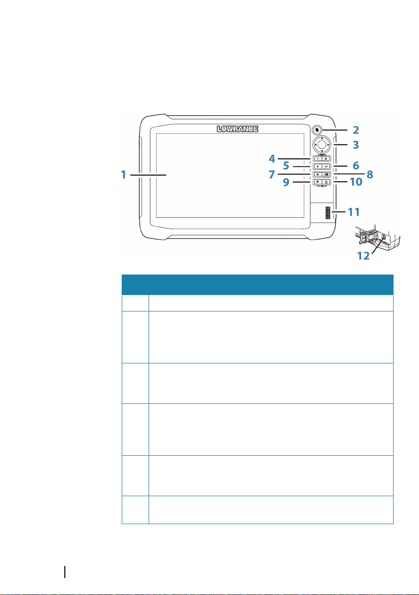
The front panel and keys
Key Description
1 Touchscreen
2 Pages key
Press once to activate the Home page. Repeat short
presses to cycle the favorite buttons. Press and hold from
an active page to go to the last used page.
3 Cursor keys
Press arrows to move through menu items, to adjust a
value, and to move the cursor on a panel.
4 Zoom Out / Zoom In keys and MOB key
Zoom keys for panels and images. Simultaneous pressing
both keys saves a Man Overboard (MOB) waypoint at the
current vessel position.
5 Exit (X) key
Press to exit a dialog, to return to previous menu level, and
to remove the cursor from the panel.
6 Enter key
Press to select or save your settings.
16
Introduction | HDS Gen3 Operator Manual
Page 17

Key Description
7 Menu key
A single press displays the menu for the active panel/
overlay. Press and hold to hide or show the menu. A quick
double-press displays the settings menu.
8 Panel key
Used on multiple-panel pages. A short press switches
between the panels, a long press expands active panel to a
full page panel and back again.
9 Waypoint key
Press to display the dialog for saving new waypoints. Press
twice to quick save a waypoint. Press and hold to access the
Find menu.
10 Power key
Press once to display the System Controls dialog. Repeat
short presses to cycle the backlight brightness. Press and
hold to turn the unit ON/OFF.
11 Card reader door
12 microSD Card readers
Introduction | HDS Gen3 Operator Manual
17
Page 18
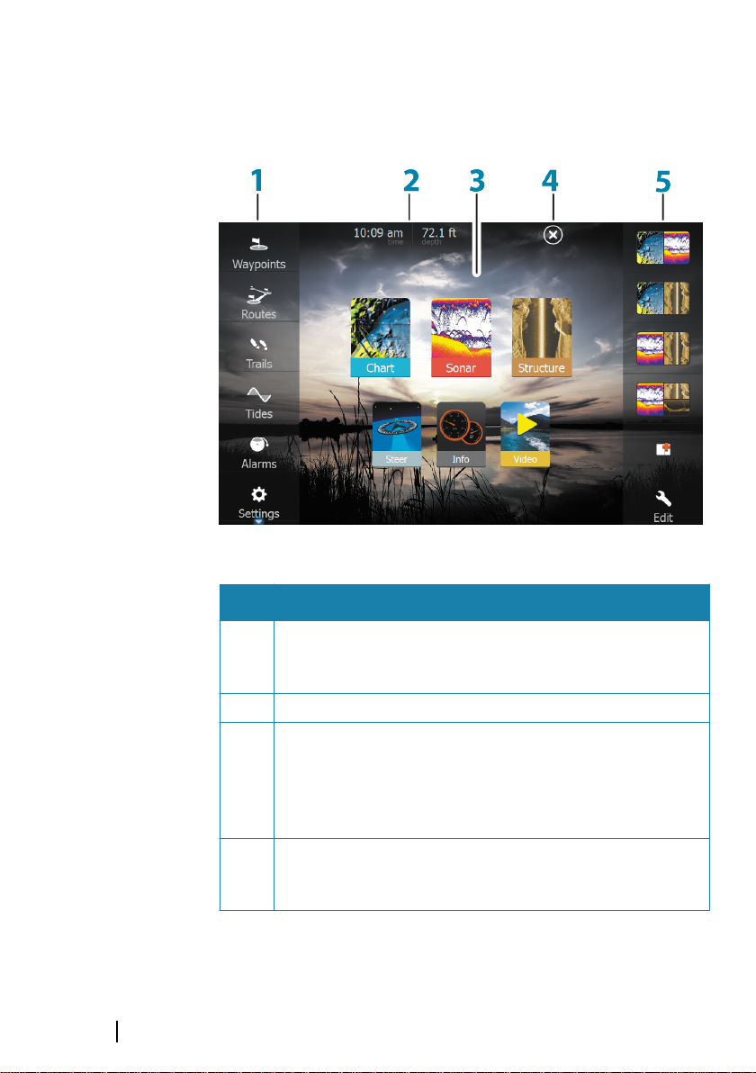
The Home page
The Home page is accessed from any operation by a short press on
the Pages key.
Key Description
18
1 Tools
Select a button to access dialogs used for carrying out a
task, or for browsing stored information.
2 Local time and Water depth
3 Applications
Select a button to display the application as a full page
panel.
Press and hold a button to display pre-configured split
page options for the application.
4 Close button
Select to exit the Home page and return to the previous
active page.
Introduction | HDS Gen3 Operator Manual
Page 19
Key Description
5 Favorites
Select a button to display the panel combination.
Press and hold a favorite button to enter edit mode for the
Favorites panel.
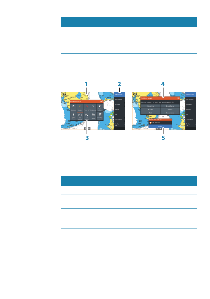
Application pages
Each application connected to the system is presented on panels.
The application can be presented as a full page, or in combination
with other panels in a multiple panel page.
All pages are accessed from the Home page.
Key Description
1 Application panel
2 Menu
Panel specific menu.
3 System Controls dialog
Quick access to basic system settings. Display the dialog by
a short press on the Power key.
4 Dialog
Information to or input from the user.
5 Alarm message
Displayed if dangerous situations or system faults occur.
Introduction | HDS Gen3 Operator Manual
19
Page 20
Split pages
You can have up to 4 panels on each page.
2 panels page 3 panels page 4 panels page
Panel sizes in a split page can be adjusted from the System
Controls dialog.
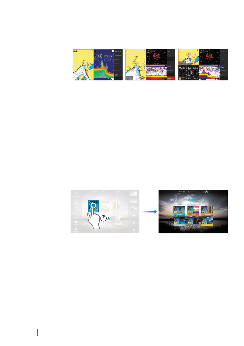
Quick split pages
Each full screen application has several pre-configured quick split
pages, featuring the selected application combined with each of
the other panels.
Ú
Access a quick split page by pressing and holding the application
button on the Home page.
Note: The number of quick split pages cannot be changed,
and the pages cannot be customized or deleted.
Favorite pages
All preconfigured favorite pages can be modified and deleted, and
you can create your own. You can have a total of 12 favorite pages.
For more information, refer to "Adding new favorite pages" on page 32.
20
Introduction | HDS Gen3 Operator Manual
Page 21

Integration of 3rd party devices
A device connected to the NMEA 2000 network should
automatically be identified by the system. If not, enable the feature
from the advanced option in the System settings dialog.
The 3rd party device is operated by using menus and dialogs as on
other panels.
This manual does not include specific operation instructions for any
3rd party device. For features and functionality, refer to the
documentation included with the 3rd party device.
Mercury VesselView integration
Mercury VesselView 7 SmartCraft data display and interaction are
enabled through the HDS Gen3 when a VesselView 7 or VesselView
4 gateway device is present on the NMEA 2000 network.
A Mercury icon appears in the Tools menu when the device is
available.
FUSION-Link integration
The FUSION-Link devices appear as additional sources when using
the audio function. No additional icons are available.
Refer to "Audio" on page 126 for more information.
BEP CZone integration
The HDS Gen3 integrates with BEP’s CZone system used for
controlling and monitoring a distributed power system on your
vessel.
The CZone icon is available in the Tools panel on the Home page
when a CZone system is available on the network.
A separate manual is provided with your CZone system. Refer to this
documentation and to the HDS Gen3 Installation manual for how to
install and configure the CZone system.
CZone dashboard
When the CZone is installed and configured, an additional CZone
dashboard is added to the Info panels.
Introduction | HDS Gen3 Operator Manual
21
Page 22

You switch between a panel’s dashboards by selecting the left and
right arrow symbols or by selecting the dashboard from the menu.
Editing a CZone dashboard
You can customize a CZone dashboard by changing the data for
each of the gauges. Available editing options depend on the type of
gauge and which data sources that are connected to your system.
For more information, refer to "Info panels" on page 91.
GoFree wireless
The HDS Gen3 includes built-in wireless functionality that lets you
use a wireless device to remotely view (phone and tablet) and
control the system (tablet only). The system is controlled from the
wireless device by Apps downloaded from their relevant
Application store.
Configuration and setup are described in the HDS Gen3 Installation
manual.
When remote control is accepted, the active page is mirrored to the
wireless device.
22
Ú
Introduction | HDS Gen3 Operator Manual
Note: For safety reasons, Autopilot and CZone functions
cannot be controlled from a wireless device.
Page 23

2
Basic operation
Systems Controls dialog
The Systems Controls dialog provides quick access to basic system
settings. You display the dialog by making a short press on the
Power key. The icons displayed on the dialog can vary. For example,
the adjust splits option is only available if you are viewing a split
page when you open the System Controls dialog.
Activating functions
Select the icon of the function you want to set or toggle on or off.
For those functions that toggle on and off, an orange bar across the
top of the icon indicates the function is activated, as shown in the
Data Overlay icon above.
Turning the system on and off
You turn the system on and off by pressing and holding the Power
key. You can also turn the unit off from the System Controls
dialog.
If the Power key is released before the shut-down is completed, the
power off process is cancelled.
Basic operation | HDS Gen3 Operator Manual
23
Page 24

Standby mode
In Standby mode, the Sonar and the backlight for screen and keys
are turned off to save power. The system continues to run in the
background.
You select Standby mode from the System Controls dialog.
Switch from Standby mode to normal operation by a short press on
the Power key.
Display illumination
Brightness
The display backlighting can be adjusted at any time from the
System Controls dialog. You can also cycle the preset backlight
levels by short presses on the Power key.
Night mode
The night mode option optimizes the color palette and backlight for
low light conditions.
24
Ú
Note: Details on the chart may be less visible when the
Night mode is selected!
Locking the touchscreen
You can temporarily lock a touchscreen to prevent accidental
operation of the system. Lock the touchscreen when large amounts
of water are on the screen, for example, in heavy seas and weather.
This feature is also useful when cleaning the screen while the unit is
turned on.
When the touch lock is active you can only operate the unit from
the keys.
Ú
You lock the touchscreen from the System Controls dialog.
You remove the lock function by a short press on the Power key.
Basic operation | HDS Gen3 Operator Manual
Note: To prevent false touchscreen activation the
touchscreen will automatically lock when it detects a
significant amount of water on the screen.
Page 25
Using menus and dialogs
Menus
The menu is used to operate the system and to adjust settings.
• Activate a menu item and toggle on/off an option by selecting
it
• Adjust a slide bar value by either:
• dragging the slide bar
• selecting the + or - icons
Select the Back menu option or the X key to return to the previous
menu level, and then exit.
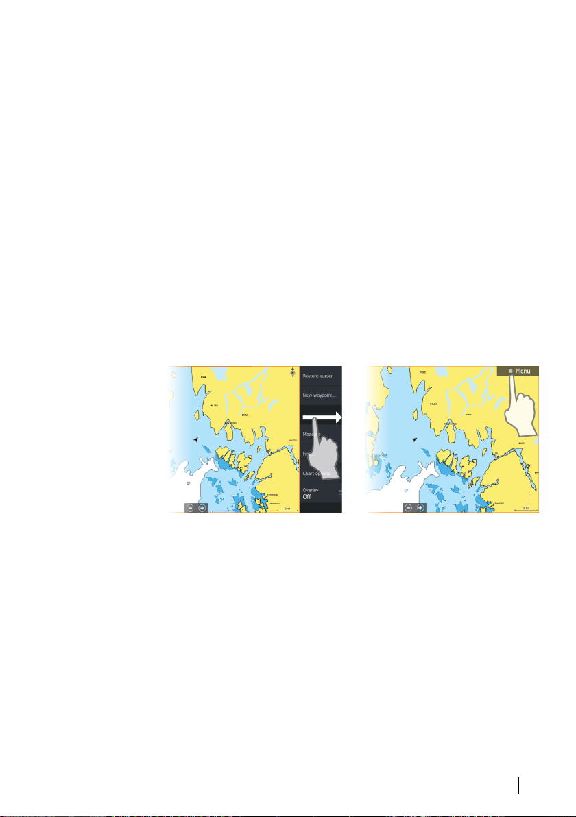
Page menus can be hidden to allow pages to be a full screen view.
To hide the menu, drag the menu to the right, or press and hold the
Menu key.
When you hide a menu on one page, the menu on other pages is
also hidden. To display the menu again, select the menu option, or
press the Menu key.
The status of the cursor (active vs. inactive) changes the menu
options.
Dialog boxes
Numeric and alphanumeric keyboards are automatically displayed
when required for entering user information in dialogs.
A dialog is closed by saving or cancelling the entry.
A dialog can also be closed by selecting the X in the dialog's upper
right corner or by pressing the X key.
Basic operation | HDS Gen3 Operator Manual
25
Page 26
Selecting pages and panels
Selecting a page
• Select a full page panel by selecting the relevant application
button on the Home page
• Select a favorite page by selecting the relevant favorite button
• Select a predefined split panel by pressing and holding the
relevant application icon
Select active panel
In a multiple panel page, only one panel can be active at a time. The
active panel is outlined with a border.
You can only access the page menu of an active panel.
You activate a panel by:
• Touch operation: tapping the panel
• Key operation: pressing the Panel key
Using the cursor on the panel
The cursor can be used to measure a distance, to mark a position,
and to select items.
Position the cursor by tapping the desired location on the screen or
by using the Cursor keys to move the cursor.
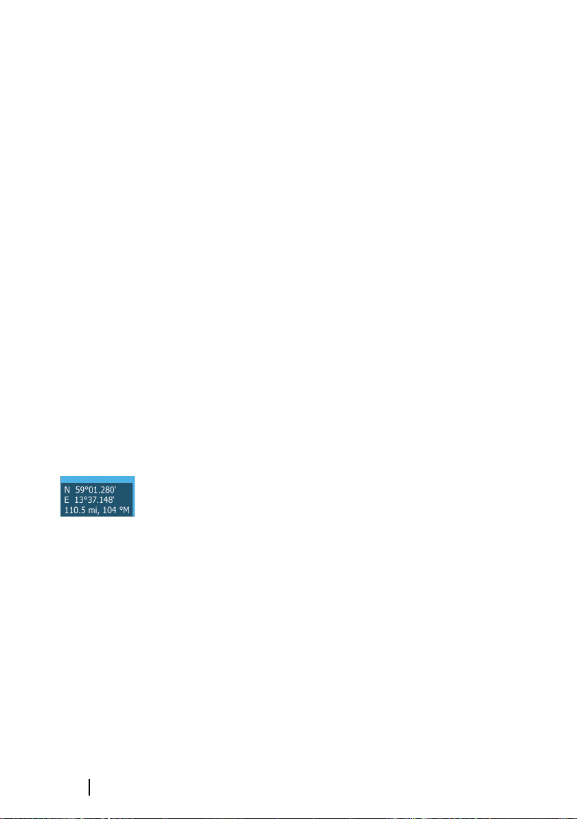
By default, the cursor is not shown on the panel.
26
When the cursor is active, the cursor position window is displayed.
To remove the cursor and cursor elements from the panel, press the
X key or select the Clear cursor option.
GoTo cursor
You can navigate to a selected position on the image by positioning
the cursor on the panel, then using the Goto Cursor option in the
menu.
The Cursor assist function
The cursor assist function allows for fine tuning and precision
placement of the cursor without covering details with your finger.
Press and hold your finger on the screen to switch the cursor
symbol to a selection circle, appearing above your finger.
Basic operation | HDS Gen3 Operator Manual
Page 27
Without removing your finger from the screen, drag the selection
circle over the desired item to display item information.
When you remove your finger from the screen the cursor reverts to
normal cursor operation.
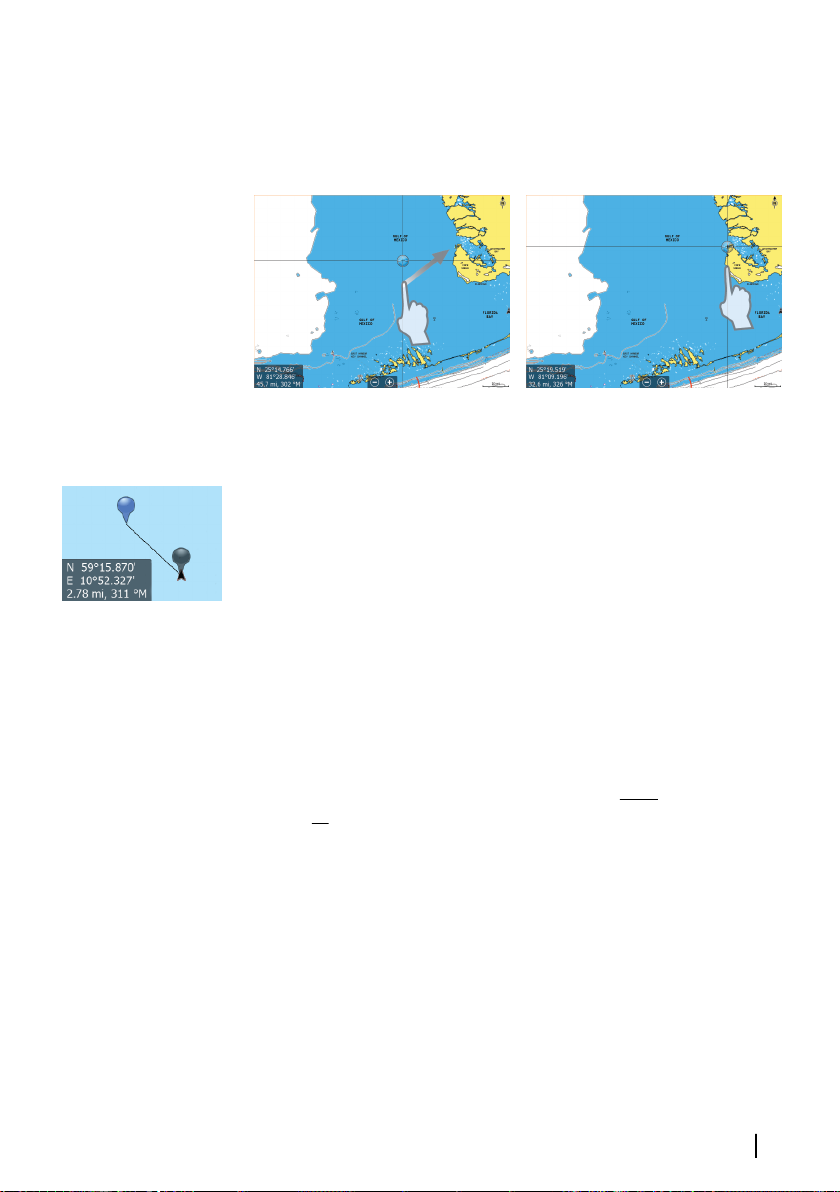
Measuring distance
The cursor can be used to measure the distance between your
vessel and a selected position, or between 2 points on the chart
panel.
1. Position the cursor on the point from where you want to
measure the distance.
2. Start the measure function from the menu.
- The measuring icons appear with a line drawn from the vessel
center to the cursor position, and the distance is listed in the
cursor information window.
3. You can reposition the measuring points by dragging either
icon as long as the measuring function is active.
Ú
You can also start the measuring function without an active cursor.
Both measuring icons are then initially located at the vessel position.
The grey icon follows the vessel as the vessel moves, while the blue
icon remains at the position given when you activated the function.
You terminate the measuring function by selecting the Finish
measuring menu option.
Basic operation | HDS Gen3 Operator Manual
Note: The bearing is always measured from the grey icon
to the blue icon.
27
Page 28
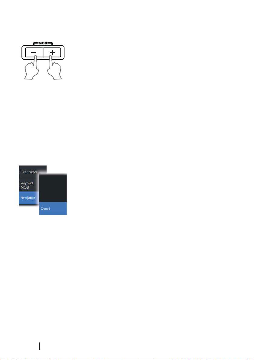
Creating a Man Overboard waypoint
If an emergency situation should occur, you can save a Man
Overboard (MOB) waypoint at the vessel’s current position by
pressing the Zoom In (+) and Zoom out (-) keys simultaneously.
When you activate the MOB function the following actions are
automatically performed:
• a MOB waypoint is saved at the vessel's position
• the display switches to a zoomed chart panel, centered on the
vessel's position
• the system displays navigation information back to the MOB
waypoint
Multiple MOB waypoints are saved by repeatedly pressing the MOB
buttons. The vessel continues to show navigation information to
the initial MOB waypoint. Navigation to subsequent MOB waypoints
needs to be done manually.
Cancel navigation to MOB
The system continues to display navigational information towards
the MOB waypoint until you cancel the navigation from the menu.
Display MOB waypoint information
You can display MOB information by selecting the MOB waypoint
and then the MOB waypoint pop-up.
28
Basic operation | HDS Gen3 Operator Manual
Page 29
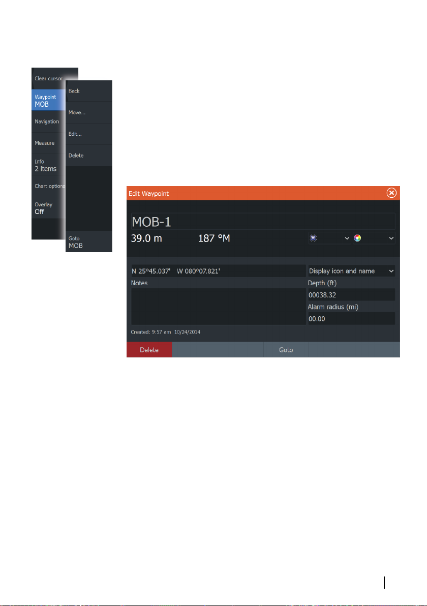
The MOB waypoint menu option
When a MOB waypoint is activated, you can use the Waypoint
MOB menu option to:
• Move it on the panel
• Edit its attributes
• Delete it
• Goto it
When you select the Edit menu option the Edit Waypoint dialog
opens.
Screen capture
Simultaneously press and hold the Pages and Power keys to take a
screen capture. By default, screen captures are saved to internal
memory.
Refer to "Tools" on page 140 for how to view files.
Basic operation | HDS Gen3 Operator Manual
29
Page 30
3
Customizing your system
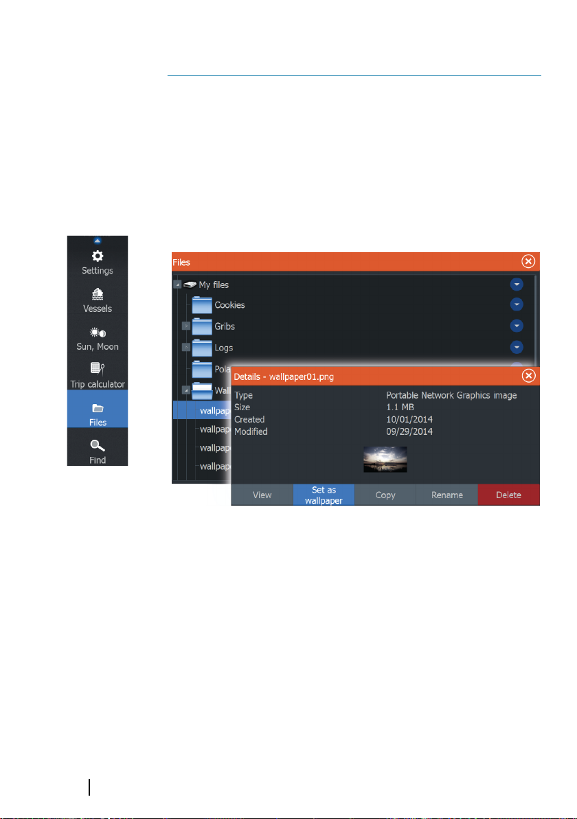
Customizing the Home page wallpaper
The Home page's wallpaper can be customized. You can select one
of the pictures included with the system, or you can use your own
picture in .jpg or .png format.
The images can be available on any location that can be seen in the
files browser. When a picture is chosen as the wallpaper, it is
automatically copied to the Wallpaper folder.
30
Adjusting panel size
You can change the panel size for an active split page. The panel
size can be adjusted for both favorite pages and for predefined split
pages.
1. Activate the System Controls dialog
2. Select the adjust splits option in the dialog
3. Adjust the panel size by:
- Touch operation: dragging the adjustment icon
- Key operation: using the cursor keys to move the adjustment
icon
Customizing your system | HDS Gen3 Operator Manual
Page 31

4. Confirm your changes by tapping one of the panels, selecting
the save option in the menu, or by pressing the Enter key.
The changes are saved to the active favorite or split page.
Data Overlay
You can have data information as overlay on a page. The
information can be any data available on the network.
Turning Data overlay on and off
You can turn overlay data on or off for any active page by selecting
the Data overlay icon on the System Controls dialog. When Data
overlay is on, an orange bar appears above the icon.
Edit overlay data
Use the Edit overlay option on the System Controls dialog to
access edit menu options to:
• Add a new data overlay to the active panel.
• Delete a selected data overlay.
• Change a selected data overlay to display different data.
• Configure a selected data overlay appearance (digital or analog,
size, and so on).
• Re-locate an item by selecting and moving it.
Customizing your system | HDS Gen3 Operator Manual
31
Page 32

Adding new favorite pages
1. Select the New icon in the favorite panel on the Home page to
open the page editor dialog
2. Drag and drop page icons to set up a new page
3. Change the panel arrangement (only possible for 2 or 3 panels),
if required.
4. Save the page layout
The system displays the new favorite page, and the new page is
included in the list of favorite pages on the Home page.
32
Edit favorite pages
1. Select the edit icon for a favorite icon to enter edit mode
- Select the X icon to remove the page
- Select the tool icon to display the page editor dialog
2. Add or remove panels in the page editor dialog.
3. Save or discard your changes to leave the favorite edit mode.
Customizing your system | HDS Gen3 Operator Manual
Page 33

4
Charts
The chart function displays your vessel’s position relative to land
and other chart objects. On the chart panel you can plan and
navigate routes, place waypoints and display AIS targets. You can
overlay a radar image, a StructureScan image or weather
information.
The Chart panel
Key Description
1 Waypoint*
2 Vessel with Heading extension line (Heading extension line
is optional)
3 Route*
4 North indicator
5 Grid lines*
6 Range rings*
7 Trail*
Charts | HDS Gen3 Operator Manual
33
Page 34

Key Description
8 Chart range scale
9 Range rings interval (only displayed when Range rings are
turned on)
* Optional chart items
Ú
Note: You turn the optional images on/off individually. For
more information, see "Chart settings" on page 47.
Chart data
The system is delivered with different embedded cartography
depending on region.
All units support Insight charts from Navico including Insight
Genesis. The system also supports Navionics Gold, Platinum+ and
Navionics+, C-MAP MAX-N/MAX-N+ by Jeppesen as well as content
created by variety of third party mapping providers in the AT5
format. For a full selection of available charts please visit
insightstore.navico.com, c-map.jeppesen.com or navionics.com.
Ú
Charts on microSD cards are shared over the Ethernet network, so
only one chart card per vessel is required.
Ú
Note: Insight charts are referred to as Lowrance in the
menu.
Note: The system does not automatically switch to
embedded cartography if the chart card is removed. A lowresolution chart will be displayed until you re-insert the
card or manually switch back to the embedded
cartography.
34
Showing dual chart types
If you have different chart types available - embedded, in the card
slot, or on the Ethernet network - you can show two different chart
types simultaneously on a page with two chart panels.
You can select a dual chart panel by pressing and holding the Chart
application button on the Home page, or by creating a favorite
page with two chart panels.
Charts | HDS Gen3 Operator Manual
Page 35

Selecting chart type
Chart type is set individually for each chart panel.
Activate one of the chart panels, and then select one of the
available chart types in the chart source menu option. Repeat the
process for the second chart panel, and select an alternative chart
type for this panel.
Vessel symbol
When the HDS has a valid GPS position lock, the vessel symbol
indicates vessel position. If no GPS position is available, the vessel
symbol includes a question mark.
Ú
Note: Without a heading sensor on the network, the vessel
icon orientates itself using COG (Course over Ground).
Chart scale
You zoom in and out on the chart by using the zoom (+ or -)
buttons, the + or - keys, or two fingers to pinch (zoom out) and
spread (zoom in).
Chart range scale and range rings interval (when turned on) are
shown in the lower right corner of the chart panel.
Panning the chart
You can move the chart in any direction by:
• Touch operation: dragging your finger on the screen
• Key operation: using the cursor keys to move the cursor to the
edge of the chart panel in the desired direction
Select the Clear cursor menu option or press the X key to remove
the cursor and cursor window from the panel. This also centers the
chart to the vessel position.
Charts | HDS Gen3 Operator Manual
35
Page 36

Positioning the vessel on the chart panel
Chart orientation
Several options are available for how the chart is rotated in the
panel. The chart orientation symbol in the panel’s upper right
corner indicates the north direction.
North up Heading up Course up
North up
Displays the chart with north upward.
Heading up
Displays the chart with the vessel’s heading directed upward.
Heading information is received from a compass. If heading is not
available, then the COG from the GPS is used.
Course up
Rotates the chart in the direction of the next waypoint when
navigating a route or navigating to a waypoint. If not navigating the
heading up orientation is used until navigation is started.
36
Look ahead
Moves the vessel icon closer to the bottom of the screen so that
you can maximize your view ahead.
Displaying information about chart items
When you select a chart item, a waypoint, a route or a target, basic
information for the selected item is displayed. Select the chart item's
pop-up to display all available information for that item. You can
also activate the detailed information dialog from the menu.
Ú
Charts | HDS Gen3 Operator Manual
Note: Pop-up information has to be enabled in chart
settings to see basic item information.
Page 37

Using the cursor on the chart panel
By default, the cursor is not shown on the chart panel.
When you activate the cursor, the cursor position window is
displayed. When the cursor is active, the chart does not pan or
rotate to follow the vessel.
Press the X key or select the Clear cursor menu option to remove
the cursor and the cursor window from the panel. This also centers
the chart to the vessel position.
Select the Restore cursor menu option to display the cursor in its
previous location. The Clear cursor and Restore cursor options
are useful features for toggling between the vessel's current
location and the cursor position.
Creating routes
You can create routes as follows on the chart panel.
1. Position the cursor on the chart panel.
2. Select New followed by New route in the menu.
3. Continue positioning the remaining routepoints.
4. Save the route by selecting the save option in the menu.
Ú
Note: For more information, refer to "Waypoints, Routes, and
Trails" on page 49.
Find objects on chart panels
You can search for other vessels or various chart items from a chart
panel.
Activate the cursor on the panel to search from the cursor position.
If the cursor is not active, the system searches for items from the
vessel's position.
Charts | HDS Gen3 Operator Manual
37
Page 38

Ú
Note: You must have a SIRIUS data package subscription to
search for fueling stations and an AIS receiver connected to
search for vessels.
3D charts
The 3D option provides a three dimensional graphical view of land
and sea contours.
Ú
When 3D chart option is selected, the Pan and the Rotate icons
appear on the right side of the chart panel.
Panning the 3D chart
You can move the chart in any direction by selecting the Pan icon
and then panning in the desired direction.
Controlling the view angle
You can control the view angle by selecting the Rotate icon and
then panning the chart panel.
• To change the direction you are viewing, pan horizontally
• To change the tilt angle of the view, pan vertically
Ú
Note: All chart types work in 3D mode, but without 3D
cartography for the appropriate area the chart appears flat.
Note: When centered on the vessel position, only the tilt
angle can be adjusted. The view direction is controlled by
the chart orientation setting. See "Positioning the vessel on the chart
panel" on page 36.
38
Charts | HDS Gen3 Operator Manual
Page 39

Zooming a 3D chart
You zoom in and out on a 3D chart by using the zoom (+ or -)
buttons, or by using the + and - keys.
Chart overlay
Radar, Structure, and Weather information can be displayed as
overlay on your chart panel.
Ú
When an overlay is selected, the chart menu expands to include
basic functions for the selected overlay.
Radar, Structure, and Weather functions are described in separate
sections in this manual.
Note: Weather overlay is currently only available in the
United States.
Insight specific chart options
Orientation, Look ahead, 3D and Change to Navionics/
Change to Insight (previously described in this section) are
common for all chart types.
Chart imagery style
The charts can be displayed in three imagery styles.
2D mapping style Shaded relief No contours
Charts | HDS Gen3 Operator Manual
39
Page 40

Insight view options
Insight Chart details
Low Basic level of information that cannot be removed, and
includes information that is required in all geographic
areas. It is not intended to be sufficient for safe
navigation
Medium Minimum information sufficient for navigation
Full All available information for the chart in use
Insight chart categories
Insight charts include several categories and sub-categories that
you can turn on/off individually depending on which information
you want to see.
40
Land Exaggeration and Water Exaggeration
Graphical settings available in 3D mode only. Exaggeration is a
multiplier applied to the drawn height of hills on land, and troughs
in water to make them look taller or deeper.
Charts | HDS Gen3 Operator Manual
Page 41

Navionics specific chart options
Orientation, Look ahead, 3D and Change to Navionics/
Change to Insight (previously described in this section) are
common for all chart types.
Community edits
Toggles on the chart layer including Navionics edits. These are user
information or edits uploaded to Navionics Community by users,
and made available in Navionics charts.
For more information, refer to Navionics information included with
your chart, or to Navionics website: www.navionics.com.
Charts | HDS Gen3 Operator Manual
41
Page 42

Navionics chart settings
Colored seabed areas
Used for displaying different depth areas in different shades of blue.
Presentation type
Provides marine charting information such as symbols, colors of the
navigation chart and wording for either International or U.S.
presentation types.
Annotation
Determines what area information, such as names of locations and
notes of areas, is available to display.
Chart details
Provides you with different levels of geographical layer information.
Safety depth
The Navionics charts use different shades of blue to distinguish
between shallow and deep water.
Safety depth, based on a selected limit, is drawn without blue
shading.
42
Ú
Note: The built in Navionics database features data down
to 20 m, after which it is all white.
Contours depth
Determines which contours you see on the chart down to the
selected safety depth value.
Rock filter level
Hides rock identification on the chart beneath a given depth.
This helps you to declutter charts in areas where there are many
rocks located at depths well below your vessel's draught.
Charts | HDS Gen3 Operator Manual
Page 43

Navionics view options
Chart shading
Shading adds terrain information to the chart.
Navionics dynamic tide and current icons
Shows tides and currents with a gauge and an arrow instead of the
diamond icons used for static tides and current information.
The tide and current data available in Navionics charts are related to
a specific date and time. The system animates the arrows and/or
gauges to show the tides and currents evolution over time.
Dynamic tide information Dynamic current information
The following icons and symbology are used:
Icons Description
Current speed.
The arrow length depends on the rate, and the
symbol is rotated according to flow direction. Flow
rate is shown inside the arrow symbol.
The red symbol is used when current speed is
increasing, and the blue symbol is used when
current speed is decreasing.
Tide height.
Charts | HDS Gen3 Operator Manual
The gauge has 8 labels and is set according to
absolute max/min value of the evaluated day.
The red arrow is used when tide is rising, and the
blue arrow is used when tide is falling.
43
Page 44

Ú
Note: All numeric values are shown in the relevant system
units (unit of measurement) set by user.
Easy View
Magnifying feature that increases the size of chart items and text.
Ú
Note: There is no indication on the chart showing that this
feature is active.
Photo overlay
Photo overlay enables you to view satellite photo images of an area
as an overlay on the chart. The availability of such photos is limited
to certain regions, and Navionics cartography version.
You can view photo overlays in either 2D or 3D modes.
No Photo overlay Photo overlay, land only Full Photo overlay
Photo transparency
The Photo transparency sets the opaqueness of the photo overlay.
With minimum transparency settings the chart details are almost
hidden by the photo.
44
Minimum transparency Maximum transparency
Charts | HDS Gen3 Operator Manual
Page 45

Navionics Fish N' Chip
The system supports Navionics Fish N' Chip (U.S. only) chart feature.
For more information, see www.navionics.com.
Depth highlight range
Select a range of depths between which Navionics fills with a
different color.
This allows you to highlight a specific range of depths for fishing
purposes. The range is only as accurate as the underlying chart data,
meaning that if the chart only contains 5 meter intervals for contour
lines, the shading is rounded to the nearest available contour line.
No Depth highlight range Depth highlight range: 6 m - 12 m
Shallow water highlight
Highlights areas of shallow water.
This allows you to highlight areas of water between 0 and the
selected depth (up to 10 meters/30 feet).
No shallow water highlighted Shallow water highlight: 0 m - 3 m
Charts | HDS Gen3 Operator Manual
45
Page 46

Jeppesen tides and currents
The system can display Jeppesen tides and currents. With this
information it is possible to predict the time, level, direction and
strength of currents and tides. This is an important tool when
considering planning and navigation of a trip.
In large zoom ranges the tides and currents are displayed as a
square icon including the letter T (Tides) or C (Current). When you
select one of the icons, tidal or current information for that location
are displayed.
Dynamic current data can be viewed by zooming inside a 1-nautical
mile zoom range. At that range, the Current icon changes to an
animated dynamic icon that shows the speed and direction of the
current. Dynamic icons are colored in black (greater than 6 knots),
red (greater than 2 knots and less than or equal to 6 knots), yellow
(greater than 1 knot and less than or equal to 2 knots) or green
(equal to or less than 1 knot), depending on the current in that
location.
If there is no current (0 knots) this will be shown as a white, square
icon.
46
Static Current and Tide icons Dynamic Current icons
Charts | HDS Gen3 Operator Manual
Page 47

Chart settings
Settings and display options made in the Chart settings page are
common for all chart panels.
3D boat selection
Determines which icon to use on 3D charts.
Boat settings
The boat settings are used when calculating an automatic route.
The boat's draught, width and height must be input to use the
autorouting and easy routing features.
Ú
Range Rings
The range rings can be used to present the distance from your
vessel to other chart objects.
The range scale is set automatically by the system to suit the chart
scale.
Charts | HDS Gen3 Operator Manual
Note: Autorouting is not available in Insight units, or in any
unit used in U.S. territorial waters.
47
Page 48

Vessels’ extension lines
Sets the lengths of the heading and course extension lines for your
vessel. For setting extension line lengths on other vessels shown as
AIS targets, refer to AIS "Course extension lines" on page 125.
A: Heading
B: Course Over Ground (COG)
The lengths of the extension lines are either set as a fixed distance,
or to indicate the distance the vessel moves in the selected time
period. If no options are turned on for the vessel then no extension
lines are shown for your vessel.
Your vessel heading is based on information from the active
heading sensor and the COG is based on information from the
active GPS sensor.
Synchronize 2D/3D chart
Links the position shown on one chart with the position shown on
the other chart when a 2D and a 3D chart are shown side by side.
Pop-up information
Selects whether basic information for chart items is displayed when
you select the item.
48
Grid lines
Turns on/off viewing of longitude and latitude grid lines on the
chart.
Hide chart
If the option is set to ON when viewing a Lowrance chart, the chart
(background) is not displayed and only the vessel, extensions,
waypoints, and routes are displayed on a white background.
Waypoints, Routes, Trails
Turns on/off displaying of these items on chart panels. Also opens
the Waypoints, Routes and Trails dialogs you can use to manage
them.
Charts | HDS Gen3 Operator Manual
Page 49

5
Waypoints, Routes, and Trails
Waypoints, Routes, and Trails dialogs
The Waypoints, Routes, and Trails dialogs give access to advanced
edit functions and settings for these items.
The dialogs are accessed from the Tools panel on the Home page
or from the chart Settings dialog.
Waypoints
A waypoint is a user generated mark positioned on a chart, on a
radar image or on the Sonar image. Each waypoint has an exact
position with latitude and longitude coordinates. A waypoint
positioned from the Sonar image has a depth value, in addition to
position information.
Waypoints, Routes, and Trails | HDS Gen3 Operator Manual
49
Page 50

A waypoint is used to mark a position you later may want to return
to. Two or more waypoints can also be combined to create a route.
Saving waypoints
You can save a waypoint at a selected location by positioning the
cursor on the panel, then selecting the new waypoint option in the
menu.
You can also save a waypoint by pressing the Waypoint key:
• Press once to display the New Waypoint dialog
• Press twice to quickly save a waypoint. If the cursor is active, the
waypoint is saved at the cursor position. If the cursor is not
active, the waypoint is saved at your vessel's position.
Moving a waypoint
50
1. Select the waypoint you want to move
The waypoint icon expands to indicate that it is active
-
2. Activate the menu and select the waypoint in the menu
3. Select the move option
4. Select the new waypoint position
5. Press the Enter key to confirm the new position.
The waypoint is now automatically saved at the new position.
Waypoints, Routes, and Trails | HDS Gen3 Operator Manual
Page 51

Edit a waypoint
You can edit all information about a waypoint from the Edit
Waypoint dialog.
The dialog can also be accessed from the Waypoints tool on the
Home page.
Waypoint alarm settings
You can set an alarm radius for each individual waypoint you create.
The alarm is set in the Edit Waypoint dialog.
Ú
Note: The waypoint radius alarm must be toggled ON in
the alarm panel to activate an alarm when your vessel
comes within the defined radius.
Routes
A route consists of a series of routepoints entered in the order that
you want to navigate them.
When you select a route on the chart panel it turns green, and the
route name is displayed.
Creating a new route on the chart panel
1. Activate the cursor on the chart panel.
2. Select the new route option from the menu.
3. Position the first waypoint on the chart panel.
4. Continue positioning new routepoints on the chart panel until
the route is completed.
5. Save the route by selecting the save option in the menu.
Waypoints, Routes, and Trails | HDS Gen3 Operator Manual
51
Page 52

Edit a route from the chart panel
1. Select the route to make it active.
2. Select the route edit option in the menu.
3. Position the new routepoint on the chart panel:
- If you set the new routepoint on a leg, a new point is added
between existing routepoints.
- If you set the new routepoint outside the route, the new
routepoint is added after the last point in the route.
4. Drag a routepoint to move it to a new position.
5. Save the route by selecting the save option in the menu.
Ú
Note: The menu changes depending on the selected edit
option. All edits are confirmed or cancelled from the menu.
Creating routes using existing waypoints
You can create a new route by combining existing waypoints from
Routes dialog. The dialog is activated by using the Routes tool
the
on the Home page.
52
Waypoints, Routes, and Trails | HDS Gen3 Operator Manual
Page 53

Converting Trails to Routes
You can convert a trail to a route from the Edit Trail dialog. The
dialog is activated by activating the trail, then selecting the trail's
pop-up, or the Trail menu option.
The Edit Trails dialog can also be accessed by selecting the Trails
tool on the Home page.
Autorouting and Easy Routing
The Autorouting and Easy Routing suggest new routepoint
positions based on information in the map and on your boat's size.
Before you can start using this feature the boat draught, width and
height must be entered into the system. The boat settings dialog is
automatically displayed if the information is missing when you start
the feature.
Ú
Ú
Ú
Waypoints, Routes, and Trails | HDS Gen3 Operator Manual
Note: HDS Gen3 units designed for sale in the U.S. region
do not have Autorouting or Easy Routing capabilities.
Autorouting or Easy Routing features are disabled on all
non-U.S. units when they are used in U.S. territorial waters.
Note: It is not possible to start the Autorouting or Easy
Routing if one of the selected routepoints is located in an
unsafe area. A warning dialog is displayed, and you have to
move the relevant routepoint(s) to a safe area to proceed.
Note: If no compatible cartography is available, the
Autorouting or Easy Routing menu option is not available.
Compatible cartography includes Jeppesen CMAP MAX-N
+, Navionics+ and Navionics Platinum. For a full selection of
available charts please visit insightstore.navico.com, cmap.jeppesen.com or navionics.com.
53
Page 54

1. Position at least two routepoints on a new route, or open an
existing route for editing.
2. Select Autorouting, followed by:
- Entire Route if you want the system to add new routepoints
between the first and the last routepoint of the open route.
- Selection if you want to manually select the routepoints that
define the limits for the autorouting, then select the relevant
routepoints. Selected routepoints are colored red. Only two
routepoints can be selected, and the system discards any
routepoints between your selected start and end points.
3. Select Accept to start the automatic routing.
-
When the automatic routing is completed the route appears
in preview mode, and the legs are color coded to indicate
save or unsafe areas. Navionics uses red (unsafe) and green
(safe), while C-MAP uses red (unsafe), yellow (dangerous) and
green (safe).
4. Move any routepoints if required when the route is in preview
mode.
5. Select Keep to accept the routepoints positions.
6. Eventually repeat step 2 (
system to automatically position routepoints for other parts of
the route.
7. Select Save to complete the automatic routing and save the
route.
Selection) and step 3 if you want the
54
Autorouting and Easy Routing examples
• Entire route option used when first and last route points are
selected.
First and last routepoint Result after automatic routing
Waypoints, Routes, and Trails | HDS Gen3 Operator Manual
Page 55

• Selection option used for autorouting part of a route.
Two routepoints selected Result after automatic routing
The Edit Route dialog
You can add and remove routepoints from the Edit Route dialog.
This dialog is activated by selecting an active route's pop-up or from
the menu.
The dialog can also be accessed by using the Routes tool on the
Home page.
Waypoints, Routes, and Trails | HDS Gen3 Operator Manual
55
Page 56

Trails
Trails are a graphical presentation of the historical path of the vessel,
allowing you to retrace where you have travelled. Trails can be
converted to routes from the Edit dialog.
From the factory, the system is set to automatically track and draw
the vessel's movement on the chart panel. The system continues to
record the until the length reaches the maximum points, and then
automatically begins overwriting the oldest points.
The automatic tracking function can be turned off from the Trails
dialog.
Creating new Trails
You can start a new trail from the Trails dialog, activated by using
the Trails tool on the Home page.
Trails settings
A trail is made up of a series of points connected by line segments
whose length depends on the frequency of the recording.
You can select to position trail points based on time settings,
distance, or by letting the system position a waypoint automatically
when a course change is registered.
56
Ú
Waypoints, Routes, and Trails | HDS Gen3 Operator Manual
Note: The Trails option must also be turned ON in the chart
settings to be visible.
Page 57

Waypoints, Routes, and Trails | HDS Gen3 Operator Manual
57
Page 58

6
Navigating
The navigation function included in the system allows you to
navigate to the cursor position, to a waypoint or along a predefined
route.
If autopilot functionality is included in your system, the autopilot
can be set to automatically navigate the vessel.
For information about positioning waypoints and creating routes,
refer to "Waypoints, Routes, and Trails" on page 49.
Steer panel
58
The Steer panel can be used to display information when you are
navigating. It is activated from the Home page, either as a full page
panel or as part of a multiple panel page.
Key Description
1 Data fields
2 Vessel heading
3 Bearing to waypoint
4 Destination point
Navigating | HDS Gen3 Operator Manual
Page 59

Key Description
5 Bearing line with allowed off course limit
When travelling on a route the bearing line shows the
intended course from one waypoint towards the next.
When navigating towards a waypoint (cursor position,
MOB, or an entered latitude and longitude position), the
bearing line shows the intended course from the point at
which navigation was started towards the waypoint.
6 Vessel symbol
Indicates distance and bearing relative to the intended
course. If the XTE (Cross Track Error) exceeds the defined
XTE limit, this is indicated with a red arrow including the
distance from the track line. Refer to ""XTE limit" on page
61".
Data Fields
The Steer panel provides the following information:
XTE Cross track error
SOG Speed over ground
COG Course over ground
POS Position
DTD Distance to destination
TTD Time to destination
Navigate to cursor position
You can start navigating to a cursor position on any chart, radar, or
Sonar panel.
Position the cursor at the selected destination on the panel, and
then select the Goto Cursor option in the menu.
Navigate a route
You can start navigating a route from the chart panel, steer panel, or
from the Route dialog.
Navigating | HDS Gen3 Operator Manual
59
Page 60

When route navigation is started, the menu expands and shows
options for canceling the navigation, for skipping a waypoint, and
for restarting the route from current vessel position.
Starting a route from the chart panel
Activate a route on the panel, and then select the route navigation
option from the menu.
You can select a routepoint to start navigating from a selected
position.
Starting a route from the steer panel
Select the start route option on the menu, and then details from the
dialogs.
Start navigating a route from the Route dialog
You can start navigating from the Route dialog, activated by:
• Selecting the Route tool from the Home page
• Selecting the route details from the menu
60
Cancel navigation
When you are navigating, the menu includes an option for
cancelling the navigation.
Navigating | HDS Gen3 Operator Manual
Page 61

Navigating with the autopilot
When you start navigation on a system with autopilot functionality,
you are prompted to set the autopilot to navigation mode.
If you choose not to engage the autopilot, the autopilot can be set
to navigation mode from the Autopilot Controller later on.
For more information about autopilot functionality, refer to "Autopilot"
on page 97.
Navigation settings
Arrival radius
Sets an invisible circle around the destination waypoint.
The vessel is considered arrived at the waypoint when it is within
this radius.
XTE limit
This setting defines how far the vessel can deviate from the selected
route, if the vessel goes beyond this limit, an alarm is activated.
XTE alarm (Cross track error)
Turns on/off the XTE alarm.
Navigating | HDS Gen3 Operator Manual
61
Page 62

Trails
Opens the Trails dialog where trails settings can be adjusted and
trails can be converted into routes for navigation. Refer to "Converting
Trails to Routes" on page 53.
Logging type
You can select to record trail points based on time, distance, or by
letting the unit position a point automatically when a course
change is registered.
Specify one of the following logging types in the Navigating
Settings dialog:
• Auto - the unit positions a point automatically when a course
change is registered.
• Distance - select the Distance field and enter the distance you
want to record.
• Time - select the Time field and enter the time you want to
record.
Phantom Loran
Enables use of Phantom Loran positioning system.
Loran settings
Defines Loran chains (GRI) and preferred station for waypoint entry,
cursor position and position panel.
The graphic example shows a cursor position window with Loran
position information.
For more information refer to your Loran system documentation.
62
Navigating | HDS Gen3 Operator Manual
Page 63

7
Sonar
The Sonar function provides a view of the water and bottom
beneath your vessel, allowing you to detect fish and examine the
structure of the sea floor.
The Sonar image
Key Description
1 Fish arches
2 History preview*
3 Temperature graph*
4 Depth at cursor
5 Amplitude scope*
6 Zoom (range) buttons
7 Water depth and Water temperature at cursor location
8 Range scale
9 Bottom
* Optional Sonar image items.
Sonar | HDS Gen3 Operator Manual
63
Page 64

Ú
Note: You turn the optional Sonar images on/off
individually. Refer to "Sonar Settings" on page 73.
Zooming the Sonar image
You can zoom the Sonar image by:
• using the zoom (+ or -) buttons
• pinching or spreading on the screen
• using the +/- keys
Zoom level is shown on the bottom left side of the panel.
When zooming in, the sea floor is kept near the bottom of the
screen, irrespective of whether it is in auto-range or manual range.
If the range is set considerably less than the actual depth, the unit is
not able to find the bottom when zooming.
If the cursor is active, the unit zooms in where the cursor is pointed.
Zoom bar
The zoom bar is displayed when you zoom the Sonar image.
Drag the zoom bar vertically to view different parts of the water
column.
Using the cursor on the Sonar panel
The cursor can be used to measure a distance to a target, to mark a
position, and to select targets.
By default, the cursor is not shown on the Sonar image.
When you position the cursor on the Sonar image; the screen
pauses, the depth at the cursor position is shown, and the
information window and the history bar are activated.
To remove the cursor and cursor elements from the panel, select
Clear cursor or press the X key.
64
Viewing Sonar history
Whenever the cursor is shown on the Sonar panel, the scroll bar is
shown at the top of the panel. The scroll bar shows the image you
are currently viewing in relation to the total Sonar image history
stored.
Sonar | HDS Gen3 Operator Manual
Page 65

If the scroll bar is on the far right side, it indicates that you are
viewing the latest soundings. If you position the cursor to the left
side of the screen, the history bar starts scrolling towards the left,
and the automatic scrolling as new soundings are received is turned
off.
You can view sonar history by panning the image. You can also use
the preview feature to pan history, refer to "Preview" on page 72.
To resume normal scrolling, select Clear cursor or press the X key.
Setting up the Sonar image
Use the Sonar menu options to set up the image. When the cursor
is active, some options on the Sonar menu are replaced with cursor
mode features. Select Clear cursor to return to the normal Sonar
menu.
The range
The range setting determines the water depth that is visible on the
screen.
Auto range
By default, the range is set to Auto. With Auto, the system
automatically displays the whole range from the water surface to
the bottom. Auto is the preferred setting for most fish finding sonar
use.
Sonar | HDS Gen3 Operator Manual
65
Page 66

Preset range levels
Allows for the selection of a specific depth range that is not tied to
the depth of the water.
Custom range
This option allows you to manually set both upper and lower range
limits.
Ú
Note: Setting a custom range puts the sonar in manual
mode. If the bottom is well beyond the lower range set,
you may lose digital depth.
Sonar frequency
The HDS Gen3 unit supports several transducer frequencies.
Available frequencies depend on the transducer model that is
connected.
You can view two frequencies at the same time by selecting dual
Sonar panels from the Home page.
Sensitivity
Increasing Sensitivity shows more detail on the screen. Decreasing
Sensitivity displays less. Too much detail clutters the screen.
Conversely, desired echoes may not be displayed if Sensitivity is set
too low.
Ú
Auto sensitivity
Auto sensitivity automatically adjusts the sonar return to the
optimal levels. Auto sensitivity can be adjusted (+/-) to your
preference while still maintaining the auto sensitivity functionality.
Note: Auto Sensitivity is the preferred mode for most
conditions.
66
Colorline
Allows the user to adjust the colors of the display to help
differentiate softer targets from harder ones. Adjusting the Colorline
can help separate fish and important structures on or near the
bottom from the actual bottom.
Sonar | HDS Gen3 Operator Manual
Page 67

Adjusting Sensitivity and Colorline
Select the Sensitivity or Colorline menu options in the Sonar menu
and adjust them by dragging the bar vertically or by using the
Cursor keys.
Ú
Ú
Note: Minor adjustments can be made by tapping above or
below the slider bar or pressing the Cursor keys.
Note: When the Sensitivity or Colorline slider bar is
displayed, it is automatically selected and adjustments can
be made up/down with the Cursor keys.
Stop sonar
Select the Stop sonar menu option to stop the sonar from pinging.
Use the stop sonar option anytime you want to disable the sonar
but not power off the unit.
Advanced Sonar options
The Advanced option is only available when cursor is not active.
Noise rejection
Signal interference from bilge pumps, engine vibration and air
bubbles can clutter the image.
The noise rejection option filters the signal interference and reduces
the on-screen clutter.
Surface clarity
Wave action, boat wakes, and temperature inversion can cause
onscreen clutter near the surface. The surface clarity option reduces
surface clutter by decreasing the sensitivity of the receiver near the
surface.
Scroll speed
You can select the scrolling speed of the Sonar image on the screen.
A high scroll speed updates the image fast, while a low scroll speed
presents a longer history.
Ú
Sonar | HDS Gen3 Operator Manual
Note: In certain conditions it may be necessary to adjust
the scroll speed to get a more useful image. Such as
67
Page 68

adjusting the image to a faster speed when vertically
fishing without moving.
Ping speed
Ping speed controls the rate the transducer transmits the Sonar
signal into the water. By default, the ping speed is set to max. It may
be necessary to adjust the ping speed to limit interference or to
adjust for specific fishing conditions.
Manual mode
Manual mode is an advanced user mode that restricts digital depth
capability, so the unit only sends sonar signals to the user selected
depth range. This allows the display to continue smooth scrolling if
the bottom depth is out of transducer range. When the unit is in
manual mode, you might not receive any depth readings, or you
might receive incorrect depth information.
Recording Sonar data
You can record Sonar and StructureScan data and save the file
internally in the HDS Gen3 unit, or save it onto a microSD card
inserted into the unit’s card reader.
The Log sonar dialog is activated from the Advanced menu
option, or the from the Sonar Settings dialog.
68
Sonar | HDS Gen3 Operator Manual
Page 69

When the Sonar image is being recorded, there is a flashing red
symbol in the top left corner and a message will appear periodically
at the bottom of the screen. The recording is stopped by selecting
the Log Sonar function and then selecting Stop.
The following options are available:
Filename
Specify the name of the recording (log).
File format
Select a file format from the drop-down, slg (Sonar only), xtf
(Structure only), or sl2 (Sonar & Structure).
Ú
Bytes per sounding
Select how many bytes per seconds that are to be used when
saving the log file. More bytes yield better resolution, but cause the
record file to increase in size compared to using lower byte settings.
Create StructureMap when completed
If StructureScan is available on the network, you can convert the
loggings to StructureMap format (.smf) after recording. The log file
can also be converted to StructureMap format from the Files option.
Note: XTF format is for use only with select 3rd party sonar
viewing tools.
Viewing the recorded sounder data
Both internally and externally stored sounder records may be
reviewed when selected.
The log file is displayed as a paused image, and you control the
scrolling and display from the replay menu option.
You can use the cursor on the replay image, and pan the image as
on a normal echo image.
If more than one channel was recorded in the selected echo file,
you can select which channel to display.
You exit the replay mode by pressing the X key or by selecting the
X symbol in the upper right corner of the replay image.
Sonar | HDS Gen3 Operator Manual
69
Page 70

Sonar view options
Select the View in the Sonar menu to see View options.
Split screen options
Zoom
70
Key Description
1 Zoom level
2 Zoom bars
The Zoom mode presents a magnified view of the sounder image
on the left side of the panel. By default the zoom level is set to 2x.
You can select up to 8x zoom from the drop-down menu, using the
+/- keys, or the zoom (+ or -) buttons. The range zoom bars on the
right side of the display shows the range that is magnified. If you
increase the zooming factor the range is reduced. You see this as
reduced distance between the zoom bars.
Sonar | HDS Gen3 Operator Manual
Page 71

Bottom lock
The bottom lock mode is useful when you want to view echoes
close to the bottom. In this mode the left side of the panel shows an
image where the bottom is flattened. The range scale is changed to
measure from the seabed (0) and upwards. The bottom and the
zero line are always shown on the left image, independent of the
range scale. The scaling factor for the image on the left side of the
panel is adjusted as described for the Zoom option.
Flasher
The Flasher mode shows a flasher-style sonar view in the left panel
and a normal sonar view in the right panel.
Palettes
You can select between several display palettes optimized for a
variety of fishing conditions.
Temperature graph
The temperature graph is used to illustrate changes in water
temperature.
When toggled on, a colored line and temperature digits are shown
on the Sonar image.
Depth line
A depth line can be added to the bottom surface to make it easier
to distinguish the bottom from fish and structures.
Sonar | HDS Gen3 Operator Manual
71
Page 72

Amplitude scope
The Amplitude scope is a display of real-time echoes as they appear
on the panel. The strength of the actual echo is indicated by both
width and color intensity.
Preview
You can have all available sonar history shown at the top of the
sonar screen. The Preview bar is a snapshot of available sonar
history. You can scroll through sonar history by dragging the
preview slider horizontally. By default, Preview is turned on when
the cursor is active.
Fish ID
You can select how you want the echoes to appear on the screen.
You can also select if you want to be notified by a beep when a fish
ID appears on the panel.
72
Traditional fish echoes Fish symbols
Ú
Sonar | HDS Gen3 Operator Manual
Note: Not all fish symbols are actual fish.
Fish symbols and depth
indication
Page 73

Sonar settings
Sonar source
If you have more than one Sonar on your network, you can select
which one to be the active source.
Network Sonar
You can share the Sonar images from this HDS Gen3 unit with other
HDS units connected on the Ethernet network.
For more information about how to setup Sonar, refer to the
separate HDS Gen3 Installation manual.
Overlay downscan
When a StructureScan unit is connected to your system, you can
overlay DownScan images on the regular echo image.
When activated, the Sonar menu expands to include basic
StructureScan options.
Select Overlay on the Structure options menu to adjust the level of
structure overlay shown on the screen. You can make adjustments
using the Overlay slider bar.
Fishing mode
This feature consists of preset packages of sonar settings designed
for specific fishing conditions.
Sonar | HDS Gen3 Operator Manual
73
Page 74

Ú
Reset fishing mode
Resets selected fishing mode to default settings, allowing you to
clear settings adjustments made while using a fishing mode.
Log sonar
You can record sonar data. This option is also available from the
Advanced option in the Sonar menu. For more information, refer to
"Recording Sonar data" on page 68.
Note: Selecting the proper fishing mode is critical to
optimal sonar performance. If you completed configuration
setup at initial startup, the proper fishing mode has already
been selected.
Fishing mode Depth Palette
General Use ≤ 1,000 ft White background
Shallow Water ≤ 60 ft White background
Fresh Water ≤ 400 ft White background
Deep Water ≤ 5,000 ft Deep Blue
Slow Trolling ≤ 400 ft White background
Fast Trolling ≤ 400 ft White background
Clear Water ≤ 400 ft White background
Ice Fishing ≤ 400 ft Ice fishing
74
View Sonar log
Used to view sonar recordings stored internally or on a microSD
card.
The log file is displayed as a paused image, and you control the
scrolling and display from the menu.
You can use the cursor on the image, measure distance, and set
view options as on a live sonar image. If more than one channel was
recorded in the selected sonar file, you can select which channel to
display.
You exit the view function by selecting the X in the upper right
corner or by pressing the X key.
Sonar | HDS Gen3 Operator Manual
Page 75

Installation
Used for Sonar installation and setup. See the separate HDS Gen3
Installation manual.
Sonar | HDS Gen3 Operator Manual
75
Page 76

StructureScan
StructureScan HD uses high frequencies to provide a high
resolution, picture-like image of the seabed.
8
Ú
StructureScan HD provides a 328 m (600 ft) wide coverage in high
detail with SideScan, while DownScan provides detailed images of
structure and fish directly below your boat, down to 92 m (300 ft).
The StructureScan page is accessed from the Home page when the
StructureScan transducer is connected and the Structure and Sonar
features are turned on in the system settings Advanced Settings
dialog.
Note: You must have a StructureScan HD transducer
installed to use StructureScan features.
The StructureScan image
The view
The StructureScan panel can be set up as a DownScan image, or
showing left/right side scanning.
The DownScan image can also be added as an overlay to the
traditional Sonar image.
76
StructureScan | HDS Gen3 Operator Manual
Page 77

Key Description
1 Depth
2 Temperature
3 Bottom
4 Frequency
5 Zoom (downscan) / Range (sidescan) icons
6 Range scale
Zooming the StructureScan image
You can zoom a StructureScan image by:
• using the zoom (+ or -) buttons
• pinching or spreading on the screen
• using the +/- keys
Zoom level is shown on the upper left side of the panel.
Using the cursor on the StructureScan panel
By default, the cursor is not shown on the StructureScan image.
When you position the cursor on a DownScan image; the screen
pauses, the cursor information window and the history bar are
activated. On a DownScan image, the depth is shown at cursor
position.
When you position the cursor on a SideScan image; the screen
pauses, and the cursor information window is activated. On a
SideScan image, the left/right distance from the vessel to the cursor
are shown at the cursor position.
StructureScan | HDS Gen3 Operator Manual
77
Page 78

To remove the cursor and the cursor elements from the panel, press
the X key or select the Clear cursor option.
Viewing StructureScan history
When the cursor is active in a DownScan view, the history bar is
shown at the top of the panel. The highlighted part of the history
bar shows the image you are currently viewing in relation to the
total StructureScan image history stored. You can pan the history by
dragging the image or the highlighted part of the history bar, to the
left or right.
In a SideScan view, you can pan the image to see sides and history
by dragging the image left, right, and up.
To resume normal StructureScan scrolling, select Clear cursor or
press the X key.
78
Setting up the StructureScan image
Use the StructureScan menu to set up the image. When the cursor
is active, some options in the menu are replaced with cursor mode
features. Select Clear cursor to return to the normal menu.
StructureScan | HDS Gen3 Operator Manual
Page 79

Range
The range setting determines the water depth that is visible on the
screen.
Auto range
When the range is set to Auto the system automatically sets the
range depending on the water depth.
Preset range levels
You can select between several preset range levels.
StructureScan frequencies
StructureScan supports two frequencies. 455 kHz provides ideal
range and image quality in most situations, while 800kHz is used to
provide higher detail in shallow water.
Contrast
The contrast determines the brightness ratio between light and
dark areas of the screen. This makes it easier to distinguish object
from the background.
To adjust the contrast setting:
1. Select the contrast icon or activate the contrast option in the
menu to display the color adjustment bar.
2. Drag the bar up or down to get the desired contrast setting or
select Auto contrast.
Ú
Note: We recommend that you use Auto contrast.
Palettes
You can select between several display palettes optimized for a
variety of fishing conditions.
View
You can set up the StructureScan page as a DownScan image, left
only, right only, or left/right side scanning.
Stop sonar
Use the Stop sonar menu option when you want to turn off the
StructureScan transducer, but not turn off the unit.
StructureScan | HDS Gen3 Operator Manual
79
Page 80

Advanced StructureScan settings
Surface clarity
Wave action, boat wakes and temperature inversions can cause onscreen clutter near the surface.
The surface clarity option reduces surface clutter by decreasing the
sensitivity of the receiver near the surface.
Ú
Note: By default, surface clarity is set to Low, for optimal
image return and clarity.
Noise rejection
Signal interference from bilge pumps, engine vibration and air
bubbles can clutter the sonar screen. The noise rejection option
filters the signal interference and reduces on-screen clutter.
Ú
Note: By default, Noise rejection is set to on, for optimal
signal returns and clarity.
Flipping the Structure image left/right
If required, the left/right SideScanning images can be flipped to
match the corresponding side of your vessel if the transducer has
been mounted backward.
Range Lines
Range lines can be added to the image to make it easier to estimate
depth (Downscan) and distance (SideScan).
Preview
You can turn off sonar history preview, have it always shown at the
top of the screen, or have it appear only when the cursor is active.
By default, the sonar history preview appears when the cursor is
active.
80
Recording StructureScan data
You can Log sonar data and save the file internally in the HDS
Gen3 unit, or onto a microSD card as described in "Recording sonar data"
on page 68.
StructureScan | HDS Gen3 Operator Manual
Page 81

9
SpotlightScan
To use the SpotlightScan feature, the SpotlightScan transducer
must be mounted on your trolling motor and its trolling motor
position sensor mounted on the trolling motor foot pedal. The
SpotlightScan feature can show structure and fish targets ahead
and around the boat without disturbing these areas before you
have a chance to fish them. Its trolling motor position sensor
ensures that the SpotlightScan returns match up correctly with the
orientation of your trolling motor. For installation instructions, refer
to the SpotlightScan Installation Manual.
The SpotlightScan transducer can be used for SpotlightScan
imaging, Downscan imaging, or as a conventional broadband/
CHIRP transducer.
The SpotlightScan transducer works with most MotorGuide and
Minn Kota cable steer trolling motors. Its scanning speed is
controlled by how fast the trolling motor is rotated with the foot
pedal.
The SpotlightScan image
SpotlightScan | HDS Gen3 Operator Manual
81
Page 82

Key Description
1 Water column
2 Bottom
3 Twin scanning beams
SpotlightScan setup
Configuring the heading sensor to the trolling motor
You must configure the heading sensor with the trolling motor foot
pedal.
1. Select Network from the Settings dialog
2. Select Device list
3. Select the position sensor (SLS-100)
4. Select Calibrate on the device information dialog
5. Select your trolling motor foot pedal
6. Select Calibrate
7. Select OK on the confirmation dialog.
Displaying SpotlightScan images
To display SpotlightScan images, the SpotlightScan feature must
first be turned on in the Advanced Settings dialog. For more
information, refer to "Tools" on page 140.
1. Select the Structure application in the Home page.
2. Select the View menu option.
3. Select the Spotlight menu option.
You can set up multiple panel pages to view SpotlightScan,
broadband sonar, and Downscan images at the same time. You
cannot view SpotlightScan and SideScan images at the same time.
82
SpotlightScan | HDS Gen3 Operator Manual
Page 83

Aligning the SpotlightScan image
You must align the SpotlightScan image with the direction the
trolling motor is pointing. If the image is not correctly aligned with
the trolling motor, the orientation of the image does not match the
underwater environment around your boat.
1. Position your trolling motor so it is pointing straight ahead
2. Access the Advanced option in the Structure menu
3. Select Position adjustment
4. Move the Position adjustment scroll bar so the top of the “V” is
centered at the top of the display.
Ú
Ú
Note: The “V” on the Structure display represents the
beams of the SpotlightScan transducer. The wide end of
the “V” should be aligned in the direction the trolling motor
is pointing.
Note: Do not use the arrow indicator on the trolling motor
head as a heading reference as it might not be aligned
correctly with the trolling motor.
SpotlightScan options
SpotlightScan menu options are available in the Structure menu.
Range
You can control how much of the area around your boat appears on
the display by increasing or decreasing the range.
Frequency
SpotlightScan can be used at 800 kHz or 455 kHz. 800 kHz provides
the highest resolution with less range. 455 kHz has the best range,
but with lower resolution.
Advanced SpotlightScan settings
Surface clarity
Wave action, boat wakes and temperature inversions can cause
onscreen clutter near the surface. The surface clarity option reduces
SpotlightScan | HDS Gen3 Operator Manual
83
Page 84

surface clutter by decreasing the sensitivity of the receiver near the
surface.
Noise rejection
Signal interference from bilge pumps, engine vibration and air
bubbles can clutter the sonar screen. The noise rejection option
filters the signal interference and reduces on-screen clutter.
Log sonar
You can Log sonar data and save the file internally in the HDS Gen3
unit, or onto a microSD card as described in "Recording Sonar data" on
page 68.
Position adjustment
You must align the SpotlightScan image with the direction the
motor is pointing. Refer to "Aligning the SpotlightScan image" on page 83.
Look Ahead
You can make the top half of the image predominant on the
display, for a better view of what is in front of you. Select Advanced
and then Look Ahead menu options in the Structure menu to
toggle it on and off.
Contrast
The contrast determines the brightness ratio between light and
dark areas of the screen. This makes it easier to distinguish object
from the background.
84
Palettes
You can select between several display palettes optimized for a
variety of fishing conditions.
View
You can select between SpotlightScan and DownScan.
Stop sonar
Pauses the sonar. Re-select to restart the sonar.
SpotlightScan | HDS Gen3 Operator Manual
Page 85

SpotlightScan operation tips
• Remove slack in the trolling motor cable to prevent image
distortion.
• Rotate the trolling motor at a slow, constant speed to achieve
the best results.
• Reducing the range increases the size of the water column,
providing the best view of fish activity beneath the boat.
SpotlightScan | HDS Gen3 Operator Manual
85
Page 86

10
StructureMap
The StructureMap feature overlays SideScan images from a
StructureScan source on the map. This makes it easier to visualize
the underwater environment in relation to your position, and aids in
interpreting SideScan images.
The StructureMap image
The example below shows a chart panel with Structure overlay,
combined with a traditional SideScan panel.
86
You move around in the chart as usual when you have a Structure
overlay:
• Touch operation: zoom the chart and the scanned image by
using the zoom (+ or -) buttons, or by pinching or spreading on
the screen. Drag on the panel to view the scanned image.
• Key operation: zoom the chart and the scanned image by using
the +/- keys.
Selecting the Clear cursor option removes the cursor from the
panel, and the chart center is positioned at the vessel.
Activating Structure overlay
1. Turn on Structure overlay from the chart menu
-
The chart menu is increased to show Structure options
- Structure data starts to appear on the chart screen as soon as
Structure overlay is enabled
StructureMap | HDS Gen3 Operator Manual
Page 87

2. Select Structure source
- Live data is default
Ú
Note: Structure overlay can also be activated by selecting a
saved StructureMap file in the files browser.
StructureMap sources
Two sources can be used to overlay Structure logs on the charts, but
only one can be viewed at a time:
• Live data - Used when StructureScan data is available on the
system.
• Saved files - These are recorded StructureScan (*.sl2) data that
are converted to StructureMap (*.smf) format. Saved *.smf files
can be used even if no StructureScan sources are connected.
Live source
When live data is selected, the SideScan imaging history is displayed
as a trail behind the vessel icon. The length of this trail varies
depending on available memory in the unit and range settings. As
the memory fills up, the oldest data is automatically deleted as new
data is added. When increasing the search range, the ping speed of
the StructureScan transducer is reduced, but the width and the
length of the image history is increased.
Note:
Ú
Live mode does not save any data. If the unit is
turned off, all recent data is lost.
Saved files
When Saved files are selected, the StructureMap file is overlaid on
the map based on position information in the file.
If the chart scale is large, the StructureMap area is indicated with a
boundary box until the scale is large enough to show Structure
details.
Saved mode is used to review and examine StructureMap files, and
to position the vessel on specific points of interest on a previous
scanned area.
Ú
StructureMap | HDS Gen3 Operator Manual
Note: When saved files are used as the source, all
StructureMap files found on the microSD card and in the
system’s internal memory are displayed. If there is more
than one StructureMap of the same area, the images
87
Page 88

overlap and clutter the chart. If several logs of the same
area are required, the maps should be put on separate
microSD cards.
StructureMap tips
• To get a picture of taller structures (a wreck, etc.) — do not
drive over it, instead, steer the boat so the structure is on the
left or right side of your boat.
• Do not use Autorange when using StructureScan. Set your
structure range to a significantly greater level (two-to-three
times) than the water depth to ensure a complete scan and to
maximize conversion accuracy.
• Do not overlap history trails when conducting a side-by-side
scan of an area.
Recording StructureScan data
StructureScan data can be recorded from a chart panel with
Structure overlay enabled.
StructureScan recordings can also be started from a StructureScan
panel.
When StructureScan data is being recorded, there is a flashing red
symbol and a message appears periodically at the bottom of the
screen.
88
Ú
The recording is stopped by re-selecting the record function.
Converting StructureScan data to StructureMap format
A StructureScan log file (.sl2) is converted to StructureMap format
(.smf ) after recording from the recording dialog, or from the files
browser.
StructureMap | HDS Gen3 Operator Manual
Note: The message includes information about file size.
Keep the size of your logs to 100MB or less to allow for
faster file conversion.
Page 89

You can create standard or high resolution files. High resolution .smf
files capture more detail, but take longer to convert and are larger
than standard resolution files.
To save disc space it is recommended to remove the StructureScan
(*.sl2) files after conversion.
Using StructureMap with mapping cards
StructureMap allows you to maintain full chart capability and can be
used with embedded cartography as well as Navionics, Insight and
other third-party charting cards compatible with the system.
When using StructureMap with mapping cards, copy the
StructureMap (.smf ) files to the unit’s internal memory. We
recommend keeping copies of StructureMap files on external
microSD cards.
StructureMap | HDS Gen3 Operator Manual
89
Page 90

Structure options
You adjust the StructureMap settings from the Structure options
menu. The menu is available when Structure overlay is enabled.
Not all options are available when saved StructureMap files are used
as the source. Unavailable options are greyed.
Range Sets the search range.
Transparency Sets the opaqueness of the Structure overlay.
With minimum transparency settings, the chart
details are almost hidden by the StructureMap
overlay.
Palette Selects Structure palette
Contrast Determines the brightness ratio between light
and dark areas of the screen.
Water column Shows/hides the water column in Live mode.
If turned OFF schools of bait fish might not be
seen on the SideScan image.
If turned ON the accuracy of the SideScan image
on the map might be affected by the water
depth.
Frequency Sets the transducer frequency used by the unit.
800 kHz offers the best resolution, while 455 kHz
has greater depth and range coverage.
Clear live
history
Log Sonar data Records StructureScan data.
Source Selects StructureMap source.
Clears existing live history data from the screen
and begins showing only the most current data.
90
StructureMap | HDS Gen3 Operator Manual
Page 91

11
Info panels
The Info panels consist of multiple gauges - analog, digital, and bar
- that can be customized to display selected data. The panel
displays data on dashboards, and you can define up to ten
dashboards within the panel.
Dashboards
A set of dashboard styles are predefined to display vessel,
navigation, and angler information.
You switch between the panel’s dashboards by selecting the left
and right arrow buttons on the panel. You can also select the
dashboard from the menu.
Vessel dashboard Navigation dashboard Angler dashboard
Ú
Note: Additional dashboards can be activated from the
menu if other systems (e.g. CZone) are present on the
network.
Customizing the Info panel
You can customize the Info panel by changing the data for each of
the gauges in the dashboard, by changing the dashboard layout,
and by adding new dashboards. You can also set limits for analog
gauges.
All edit options are available from the Info panel menu.
Available editing options depends on which data sources are
connected to your system.
Info panels | HDS Gen3 Operator Manual
91
Page 92

Edit a dashboard
Activate the dashboard you want to edit, then:
1. Activate the menu.
2. Select the edit option.
3. Select the gauge you want to change. Selected gauge is
indicated with a blue background.
4. Select information to be displayed, configure limits, and
eventually change the source for the information.
5. Save your changes by selecting the save option in the menu.
92
Info panels | HDS Gen3 Operator Manual
Page 93

Video
The video function allows you to view videos or camera sources on
your system.
12
Ú
Note: The video images are not shared from the Ethernet
network. You can only view the video on the unit
connected to the video source.
The Video panel
A video panel can be set up as a single panel, or as one of the
panels on a multiple panel page.
The video image is proportionally scaled to fit into the video panel.
Areas not covered by the image are colored black.
Setting up the video panel
Video source
HDS Gen3 supports one video input channel.
Video standard
HDS Gen3 supports NTSC and PAL video. Check the local video
standard or the standard of your cameras.
Adjusting the video image
You can optimize the video display by adjusting the video image
settings. Default for all settings: 50%.
Video | HDS Gen3 Operator Manual
93
Page 94

13
Simulator
The simulation feature lets you see how the unit works in a
stationary position and without being connected to the Sonar,
Radar, GPS, etc.
Use the simulator to become familiar with your unit before using it
on the water.
94
Demo mode
In this mode the unit automatically runs through the main features
of the product; it changes pages automatically, adjusts settings,
opens menus, and so on.
If you tap on a touchscreen or press a key when demo mode is
running, the demonstration pauses. After a time-out period, demo
mode resumes and any changed settings are restored to default.
Ú
Simulator | HDS Gen3 Operator Manual
Note: Demo mode is designed for retail/showroom
demonstrations.
Page 95

Simulator source files
You can select which data files are used by the simulator. A set of
source files is included in your system, and you can import files by
using a microSD card inserted into the card reader. You can also use
your own recorded files in the simulator.
Advanced simulator settings
The Advanced simulator settings allows for manually controlling the
simulator.
GPS source
Selects where the GPS data is generated from.
Speed, Course and Route
Used for manually entering values when GPS source is set to
Simulated course or Simulated route. Otherwise, GPS data including
speed and course come from the selected source file.
Simulator | HDS Gen3 Operator Manual
95
Page 96

Set start position
Moves your vessel to the current cursor position.
Ú
Note: This option is only available when the GPS source is
set to Simulated course.
96
Simulator | HDS Gen3 Operator Manual
Page 97

14
Autopilot
If a MotorGuide Xi5 trolling motor with Pinpoint GPS is connected
to the network, then the SmartSteer (autopilot) functionality is
available on your HDS Gen3.
To use trolling motor autopilot functionality, you need the
following:
• MotorGuide Xi5 trolling motor with Pinpoint GPS (available
from MotorGuide)
• MotorGuide Pinpoint GPS Gateway (available from MotorGuide)
• NMEA 2000® network.
For details about installing this equipment, refer to the separate
installation manuals that come with the equipment.
The Autopilot can automatically control the trolling motor to:
• Maintain a set heading
• Maintain the vessel's position
• Navigate to the cursor position, to a waypoint, or along a route
• Follow pre-defined turn patterns
Xi5 trolling motor software
You may have to update the software in the MotorGuide Xi5 trolling
motor to use it with the Lowrance SmartSteer interface. If an update
is necessary, a Trolling motor update dialog appears on your
networked HDS unit(s). The update process is initiated through an
HDS unit. Follow the onscreen instructions to update Xi5 software.
Safe operation with the autopilot
Warning: An autopilot is a useful navigational aid,
but DOES NOT replace a human navigator.
Switching from automatic navigation to standby mode
To switch from autopilot to handheld remote or foot pedal steering,
set the autopilot to standby mode. You can select standby mode
from the Autopilot Controller or the System Controls dialog.
Autopilot | HDS Gen3 Operator Manual
97
Page 98

Autopilot interface
Key Description
1 Autopilot information bar
2 Autopilot Controller
The Autopilot Controller
98
The autopilot is controlled from the Autopilot Controller,
activated from the System Controls dialog displayed by pressing
the Power key.
You can select the position of the Autopilot Controller on the page.
Refer to "Autopilot settings" on page 104.
Ú
The Autopilot Controller can also be set up as a panel in a split
panel page by using the Page Editor to make a Favorite page. For
information about Favorite pages, refer to "Adding new favorite pages" on
page 32.
Autopilot | HDS Gen3 Operator Manual
Note: As long as the Autopilot Controller is active, you
cannot operate the background panel or its menu.
Page 99

The Autopilot information bar
The Autopilot information bar is displayed when an autopilot
mode is selected. The bar includes information about the autopilot
mode and navigational information. The bar is present on all pages
if the autopilot is in an active mode. In the Autopilot settings dialog,
you can select that the bar is off when the autopilot is in standby
mode. Refer to the "Autopilot settings" on page 104.
Autopilot control of the trolling motor
Selecting an Arrival mode
The autopilot switches from navigation mode to the selected arrival
mode when your vessel reaches the destination. Arrival mode is set
to Standby by default. Before starting a navigation mode or a turn
pattern, it is important to select an arrival mode that fits your
navigation needs. Refer to "Arrival mode" on page 104.
Anchor mode
Maintains your vessel position at a selected location.
Ú
Autopilot | HDS Gen3 Operator Manual
Note: When in anchor mode, your vessel orientation can be
affected by wind or currents.
Anchor mode
Waypoint Enables anchor mode when your vessel arrives at
a selected waypoint.
Cursor Enables anchor mode when your vessel arrives at
the cursor position.
Here Enables anchor mode at your current location.
99
Page 100

Heading Lock mode
Locks and maintains the current vessel heading. Use the left and
right arrow buttons in the Autopilot Controller to make heading
adjustments. To make small heading adjustments, single-select the
left or right buttons. For larger adjustments, select and hold the left
or right buttons.
Standby mode
Cancels autopilot activity and returns the vessel to handheld remote
or foot pedal steering control.
Turn pattern steering
Steers the vessel in predefined turn patterns. When you select a turn
pattern, the system creates temporary waypoints on the turn. The
last waypoint on the turn is the final waypoint. When the vessel
reaches the final waypoint, the vessel goes into arrival mode. Refer
to "Arrival mode" on page 104.
Setting up a turn pattern
1. Select a turn pattern.
2. Enter the desired value(s) in the turn pattern dialog or use
default settings.
3. Select the direction of the turn.
100
Ú
Note: Selecting a turn radius smaller than the GPS accuracy
may result in incomplete navigation of the turn pattern.
U-turn
Changes the current set heading to be 180° in the opposite
direction.
Autopilot | HDS Gen3 Operator Manual
 Loading...