

Lowrance AIRMAP 500, AIRMAP 1000, AIRMAP 100 User Manual

TM
AirMap
INSTALLATION AND
OPERATION INSTRUCTIONS
VERSION 3.3

Copyright © 1996, 1997 Lowrance Avionics
All rights reserved.
Lowrance® is a registered trademark of Lowrance Electronics, Inc.
IMS SmartMap™ is a trademark of Lowrance Electronics, Inc.
Jeppesen® is a registered trademark of Jeppesen Sanderson, Inc.
WARNING!
USE THIS MAPPING UNIT ONL Y AS AN AID TO NA VIGA TION. A CAREFUL NAVIGATOR NEVER RELIES ON ONLY ONE METHOD TO OBTAIN POSITION INFORMATION.
Never use this product while operating a vehicle.
The background map built into this unit is not intended f or navigation and
its accuracy has not been verified. This map is deriv ed from U .S. government sources which rely on ground and aerial surveys and satellite data.
Since there can be inaccuracies in the data used to create the maps and
in the map’s resolution, plus position inaccuracies in the navigation system, use caution when using this product.
CAUTION
When showing navigation data to a position (wa ypoint), this unit will show
the shortest, most direct path to the waypoint. It pro vides navigation data
to the waypoint regardless of obstructions. Therefore , the prudent navigator will not only take advantage of all a vailable na vigation tools when travelling to a waypoint, but will also visually check to make certain a clear,
safe path to the wa ypoint is alw ays available.
The storage temperature for y our unit is from -4 degrees to +167 degrees
Fahrenheit (-20 to +75 deg rees Celsius). Extended stor age temperatures
higher or lower than specified will cause the liquid crystal display to fail.
Neither this type of failure nor its consequences are cov ered b y the warranty . For more information, consult the factory customer service department.
All features and specifications subject to change without notice.
All screens in this manual are simulated. Many were taken with an IMS
SmartMap™ loaded into one of the cartridge slots.

INTRODUCTION .......................................................................................................... 1
INSTALLATION............................................................................................................. 2
BATTERY INSTALLATION ............................................................................................ 3
EXTERNAL POWER .................................................................................................... 4
ANTENNA..................................................................................................................... 5
REMOTE ANTENNA MOUNT...................................................................................... 5
MAP CARTRIDGE INSTALLATION ............................................................................. 6
REMOVING MAP CARTRIDGE ................................................................................... 7
YOKE MOUNT .............................................................................................................. 8
KEYBOARD .................................................................................................................. 9
OPERATION ................................................................................................................. 10
TURNING POWER ON ................................................................................................ 10
MENUS ......................................................................................................................... 10
FINDING YOUR POSITION .......................................................................................... 10
COLD START ............................................................................................................... 10
INITIALIZATION ........................................................................................................... 11
ENTER BY MAP........................................................................................................... 11
ENTER MANUALLY...................................................................................................... 13
POSITION/NAVIGATION DISPLAYS ........................................................................... 14
NAVIGATION SCREENS ............................................................................................. 15
CDI INDICATOR ........................................................................................................... 16
MAPPING SCREENS .................................................................................................. 17
AUTOZOOM ................................................................................................................. 19
MAP CURSOR ............................................................................................................. 20
MAP SYMBOLS ........................................................................................................... 21
OBSTRUCTIONS ......................................................................................................... 21
AIRSPACE .................................................................................................................... 23
AIR MAP OPTIONS ..................................................................................................... 24
MAP ORIENTATION ..................................................................................................... 25
EARTH MAP OPTIONS ............................................................................................... 26
C-MAP OPTIONS......................................................................................................... 28
PLOTTER OPTIONS.................................................................................................... 29
ICONS .......................................................................................................................... 31
WINDOWS.................................................................................................................... 33
REPROGRAM WINDOW GROUPS............................................................................. 33
SATELLITE INFORMATION SCREEN ......................................................................... 35
DUAL MAPPING ........................................................................................................... 37
CLOCK ......................................................................................................................... 37
TIMERS ........................................................................................................................ 3 9
REPROGRAM BOXES................................................................................................. 40
DATABASES ................................................................................................................. 42
SAVING PRESENT POSITION AS A WAYPOINT (QUICK SAVE)............................. 46
SAVING CURSOR POSITION AS A WAYPOINT ........................................................ 47
SAVING PRESENT POSITION AS A WAYPOINT (SELECT WAYPOINT #).............. 47
SAVING CURSOR POSITION AS A WAYPOINT (SELECT WAYPOINT #) ............... 47
EDIT WAYPOINT LAT/LON .......................................................................................... 48
WAYPOINT NAMES ..................................................................................................... 48
WAYPOINT ICONS ...................................................................................................... 49
DELETE A WAYPOINT ................................................................................................ 49
MOVE A WAYPOINT .................................................................................................... 50
DISTANCE BETWEEN WAYPOINTS........................................................................... 50
WAYPOINT OPTIONS.................................................................................................. 51
ROUTES ....................................................................................................................... 51
SELECT WAYPOINTS - WAYPOINT LIST................................................................... 52
SELECT WAYPOINTS - FROM MAP........................................................................... 53

FINISHING THE ROUTE .............................................................................................. 53
FOLLOWING A ROUTE ............................................................................................... 54
DELETE A ROUTE....................................................................................................... 55
NAVIGATION ................................................................................................................ 55
NAVIGATE TO A DATABASE LOCATION .................................................................... 55
NAVIGATE TO CURSOR POSITION ........................................................................... 56
NAVIGATE TO A WAYPOINT USING THE MAP ......................................................... 56
“NEAREST” .................................................................................................................. 57
CANCEL NAVIGATION ................................................................................................ 58
SYSTEM SETUP.......................................................................................................... 58
TRACK HOLDING ........................................................................................................ 58
GPS CORRECTIONS .................................................................................................. 59
DATUM .......................................................................................................................... 59
PCF (POSITION CORRECTION FACTOR)................................................................. 60
UNITS OF MEASURE .................................................................................................. 61
POSITION FORMAT .................................................................................................... 61
NMEA/DGPS ................................................................................................................ 62
SERIAL COMMUNICATION SETUP ............................................................................ 65
RESET OPTIONS ........................................................................................................ 65
RESET GROUPS ......................................................................................................... 65
SYSTEM INFO ............................................................................................................. 65
NAME INPUT ............................................................................................................... 66
GPS SETUP ................................................................................................................. 66
GPS UPDATE RATE/BATTERY SAVE......................................................................... 67
POSITION PINNING .................................................................................................... 67
EXECUTE GPS SELF-TEST ....................................................................................... 67
EXECUTE GPS COLD STA RT .................................................................................... 68
ALARMS ....................................................................................................................... 69
MESSAGES.................................................................................................................. 70
BACKLIGHT ................................................................................................................. 71
CONTRAST .................................................................................................................. 72
SPEAKER ON/OFF ...................................................................................................... 72
SIMULATOR ................................................................................................................. 72
E6B COMPUTER ......................................................................................................... 74
BATTERIES .................................................................................................................. 76
DEFINITION OF TERMS/ABBREVIATIONS ............................................................... 76
JEPPESEN UPGRADE................................................................................................ 77
WINDOW BOXES......................................................................................................... 78
WINDOW GROUPS ..................................................................................................... 80
UPS RETURN POLICY ................................................................................................ 82
WARRANTY ................................................................................................................. 84
DATABASE LICENSE AGREEMENT........................................................................... 85
DATABASES LIMITED WARRANTY............................................................................ 86
HOW TO OBTAIN SERVICE - INTERNATIONAL .......................... INSIDE BACK COVER
HOW TO OBTAIN SERVICE - U.S.A. ONLY ................................................BACK COVER

INTRODUCTION
Thank you for purchasing a Lowrance Avionics AirMap™. With its large
LCD screen, easy to use menus, and outstanding performance, we think
you’ll be happy with y our AirMap for many y ears. No other handheld GPS
receiver on the market toda y has the AirMap’s combination of 12 channel
receiver , Jeppesen® database with obstacles (U.S . only), ground and h ydrographic mapping cartridge capability , and programmable screens in a
handheld unit.
Like most GPS receivers, your AirMap doesn’t have a compass or any
other navigation aid built into it. It relies solely on the signals from the
satellites to determine its position. Speed, direction of tra vel, and distance
are all calculated from position information. Therefore, in order for it to
determine the direction you’re travelling, you must be moving, and the
faster - the better . This is not to say the unit w on’t work at walking speeds
- it will. But the faster you travel, the easier it is for the unit to determine
your direction.
GPS works from satellites that transmit information to the world at very
high frequencies. One disadvantage to this frequency is that it’s “line-ofsight”. In other words, the signals don’t bounce around like your local
radio or television. If you don’t have a clear view of the sky, or if you’re
inside a metal building, the unit probably won’t be able to pick up the
signals from the satellites. This is common among all GPS receivers . W e
have f ound that using this product inside an aircraft is usually sufficiently
close to the windows and windshield that it works well. However, the included remote antenna bracket and cable (model PA-2) lets you mount
the removab le antenna on top of the dash, in case it’s required.
Another factor that influences the GPS’ position and navigation capabilities is called selective av ailability or SA. This is small errors purposefully
injected into the transmitted signal from the satellites. The government
does this to degrade the system’ s accur acy to civilian and f oreign users.
Even with SA, GPS is the most accurate na vigation system ever inv ented
on such a large scale. The Gover nment’s accuracy specification is 100
meters horizontally and 150 meters vertically 95% of the time. In other
words, the position shown on your AirMap could be up to 100 meters in
any direction from your actual position, and the altitude could be plus or
minus 150 meters from what’ s shown on the screen, 95% of the time .
One way around the S/A problem is to purchase a DGPS receiver and
connect it to your AirMap. A DGPS receiver (commonly called a beacon
receiver), picks up correction signals broadcast from ground stations . The
1

AirMap takes these corrections and applies them to the position and altitude screens, giving you much better accuracy. Even with S/A on, and
without a DGPS receiver , your AirMap gives y ou outstanding position and
navigation information.
Please sit down with the unit and this manual and f amiliarize yourself with
them before using this unit in the “real w orld”. A sim ulator is built in, which
lets you practice with the receiver.
INSTALLATION
The AirMap operates from six AA batteries or from 6 to 35 volts DC. The
cigarette lighter adapter included with your unit plugs into virtually any
aircraft’ s electrical system. The AirMap automatically switches to e xternal
power when it’s plugged into the unit (provided that the external power
has a higher voltage than the batteries.) If, for any reason, the external
power fails , the unit will automatically s witch to the batteries. The AirMap
does not require batteries when external power is in use, however they
make a good backup in case of power failure. A rechargeable battery
pack, (optional) has a nickle-metal h ydride battery and charger built into a
pack that’s almost identical to the alkaline battery pack that slides onto
the bottom of the AirMap.
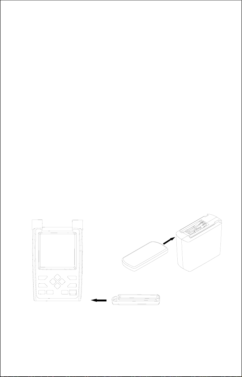
An external antenna kit supplied with the unit allows the removable antenna to be mounted on a suction cup bracket up to four feet away from
the GPS receiver .
NiMH BATTERY
SUCTION CUP
AND BRACKET
2

BATTERY INSTALLATION
The AirMap requires six AA batteries. We recommend DURA CELL® alkaline batteries, but other brands will work. You can use lithium batteries
which will last longer than alkaline batteries (but cost more) or rechargeable ni-cad batteries (won’t last as long as standard alkalines). Rechargeable alkaline batteries such as RayOVac® Renewals® will also work .
Do not use heavy-duty batteries or any battery other than the ones listed
above. Do not mix different types of batteries. (For example, don’t use
both alkaline and ni-cad batteries at the same time.)
To install the batteries, first turn the AirMap so that it is facing you. Now
grasp the bottom part of the case and push it to the right until it comes
completely off the unit. The bottom
part of the case holds the batteries.
Next, push the battery holder out the
bottom of the battery cover as
shown below. Install each battery
with the negative end (-) against the
spring. The positiv e end (+) of each
battery should be firmly against the
metal plate. When all six batteries
are installed, slide the battery holder
into the battery cover .
If the battery holder sticks when sliding into the battery cover, apply a
thin film of petroleum jelly to the “O”
rings on the battery holder.
3
IMPORTANT!
There are arrows molded into the bottom of the battery cover and battery
holder. Mak e certain the arrows are properly aligned! Otherwise, the battery holder won’t slide all the way into the cover and the battery pack
won’t slide onto the unit.
Slide the battery pack onto the unit and the AirMap is ready for use.
EXTERNAL POWER
Instead of batteries, the AirMap can operate on 6 to 35 volts DC from an
external power source. To use external power, an adapter cable is supplied with your unit that will plug into your v ehicle’s cigarette lighter . To use
this cable, simply plug one end into the AirMap and the other end into the
cigarette lighter. A rubber plug is supplied with your AirMap to cover the
external power jack on the side of the unit when it’s not in use.
You can leave the battery pack on when using external power , no damage
to the batteries or the unit will occur. However, if you remove the battery
pack from the AirMap, we recommend that the battery contact cover be
placed onto the battery pack as shown below . This will pre vent the battery
pack contacts from shorting against metal objects.
A separate cover is pro vided f or the bottom of the AirMap .
4
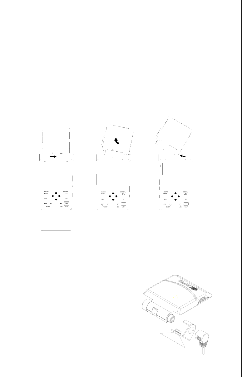
ANTENNA
Your AirMap has a removable antenna that folds over the display when
the unit is not in use. This prevents damage to the display. To open the
antenna, simply lift on an edge and raise it to the desired position. The
antenna is a quick release design, simplifying its remov al and installation.
To remove the antenna, push the antenna to the right (1), while simultaneously moving the antenna up (2), until it clears the AirMap's right side
(3). To replace the antenna, reverse the above steps. Make certain to
align the antenna with the AirMap until the antenna slides into place to the
left by itself. When it does, the antenna has mated with the connector
inside the unit and it’s ready f or use.
1. 2. 3.
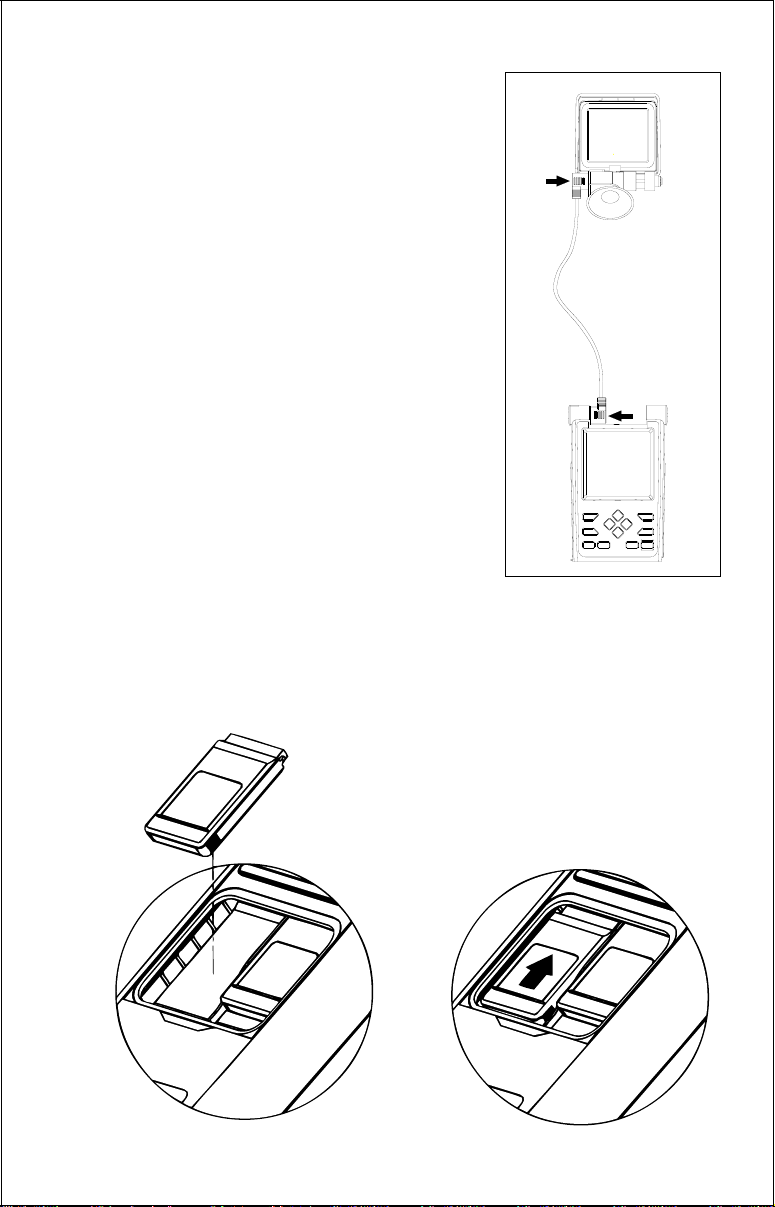
Remote Antenna Mount
The remote antenna kit lets you mount the
AirMap's antenna up to four feet a way. The
suction cup mount can be installed on virtually any flat surface .
First press the suction cup into the hole in
the bottom of the bracket. Next, remove
the antenna from the AirMap and slide the
suction cup bracket over the antenna as
shown at right. Press the antenna cab le
5
over the suction cup brac k et and onto the antenna. This locks the bracket onto the bracket
with a friction fit. Press the other end of the
cable firmly onto the AirMap's left antenna
mounting bracket. Moisten the suction cup and
press it onto any clean, smooth surface. The
unit is now ready for use.
MAP CARTRIDGE INSTALLATION
The AirMap uses Jeppesen®, IMS SmartMap™ and WorldMap™, and C-Map™ cartridges, all of which are packaged in a cartridge
housing specifically designed for Lowrance
mapping products.
The IMS SmartMap™ cartridges contain digitized data of over 120,000 bodies of water.
Nearly all inland waterways-public and private
lakes, rivers, and streams , plus coastal United
States waters up to 25 miles out are included.
There are also state and U.S. interstate highways and routes , cities and towns. These inland mapping cartridges cover
the entire continental United States in 64 highly detailed cartridges. The
WorldMap™ cartridges cover all other areas of the world, showing more
detail than the background map, but not as much as the SmartMap™
areas.
LEI IMS
TEXAS
NORTH
AMERICAS
DATABASE
LEI IMS
AMERICAS
DATABASE
6
AMERICA’S
DATABASE
The C-Map cartridges cover most of the world with detailed views of coastal
and some inland waters. Ov er 600 cartridges are available.
The Jeppesen® database cartridge contains the location of VOR’ s, NDB’ s,
intersections, and airports. It also has airport information such as runway
length and widths, frequencies, fuel availablity, and more. These cartridges can be updated every 28 days. See page 80 for Jeppesen database update information.
To install a cartridge into the AirMap,
off.
Never install or remove a cartridge with the unit turned on! You
first make certain the unit is turned
can damage your unit if you install or remove a cartridge with the unit
turned on. Next, pry the cov er off the back of the unit. Place the cartridge
into either slot with it’s label facing you as shown at the bottom of the
previous page. Now slide the cartridge towards the top until it stops. Replace the cover .
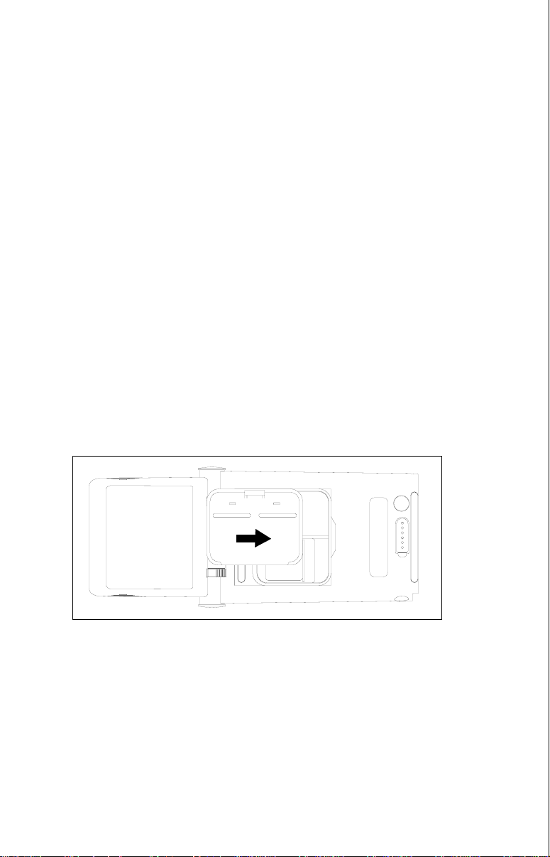
REMOVING A CAR TRIDGE
If you have difficulty removing a cartridge, use the back cover as a removal tool. Simply press one side of the cover against the ridge on the
cartridge and gently push towards the bottom of the unit. Don’t use a
corner of the cover - it could damage it.
IMPORTANT!
If you unplug the Jeppesen cartridge and turn the AirMap on, or if you
swap y our Jeppesen cartridge for a newer one,
all routes are erased!
No
waypoints will be erased - only routes. Make certain to write down any
stored routes before sw apping cartridges.
7

Y OKE MOUNTING
Included with your AirMap is a yoke mounting bracket. It secures to the
yoke’s shaft with a clamp. Follow the instructions included with the yoke
mount to assemble and attach it to your aircraft. The AirMap attaches to
the yoke mount with hook and loop material which is already attached to
the back of your unit. Simply press the AirMap onto the hook and loop
material that’s on the yok e mount.
Make certain to push the antenna back as far as it will go. It needs to be
as parallel to the ground as possible in order to receive signals from the
satellites. See the dr awings belo w for a typical installation.
When the AirMap is attached to the yoke mounting brac ket, it can operate
from batteries or the external power cord. To use the external power cord,
simply plug one end into the power connector on the right side of the
AirMap and the other end into the aircraft’s cigarette lighter.
8

KEYBOARD
The keyboard has twelve keys. The arrow keys are tied to most of the
features, letting you easily move the mapping cursor, navigate through
the menus, make selections from men us, and other tasks .
PAGES
MENU
Z-OUT Z-IN ENT PWR
WPT
EXIT
The WPT k ey lets y ou create, sav e, and recall wa ypoints and routes. The
P A GES key s witches the unit between the three major displays: windows ,
navigation, and mapping. To select different features, or to modify functions, press the MENU key. The Z-OUT and Z-IN keys z oom-out and zoomin your view on the mapping screen. The ENT and EXIT keys let y ou enter
or erase selections. The ENT ke y w orks the same as the right arrow key
for selecting features . In other words, you can use the ENT k ey instead of
the right arrow key to select a menu or enter data. The PWR key turns
both the AirMap and its lights on and off.
Note: To prev ent an accidental po wer shutdown, y ou must hold the PWR
key down for a few seconds in order to turn the unit off.
9
OPERATION
Turning Power On
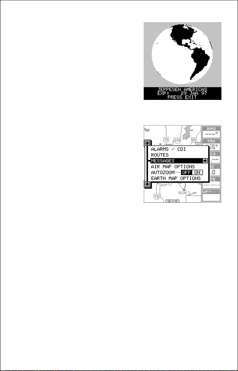
To turn the AirMap on, simply press the
PWR key. A screen similar to the one at
right appears. The database cartridge’s
name and expiration date appears at the
bottom of this screen. Press the EXIT k ey
to erase it. A warning message appears
next, press the EXIT ke y to er ase it, also.
MENUS
Most of the adjustments and features are
found on “men us”. Pressing the MENU k ey
lets you view the menus . Different menus
items are added or subtracted to the basic list, depending on which mode (mapping, navigation, or windows) the unit is
in. This gives y ou the features that are specific to the mode you are in, but also has
items that are used on all modes.
T o er ase the main menu, simply press the
EXIT key.
Finding Y our Position
Cold Start
When it’s turned on for the v ery first time, the GPS receiver doesn’t kno w
where it is, nor what the local time or date is. If you tell it your position,
time, and date, the unit will take less time to lock-on to the satellites and
give you a fix or position.
However, if you don’t want to push buttons at this time, that’s fine. The
AirMap will lock onto the satellites and give you a position without any
input from you. This is called a “cold-start”. It simply means that the unit is
searching without your help for the satellites that are in orbit. A cold-start
can take up to 5 minutes to acquire enough satellite data to determine
your position, although it typically takes less time than that.
Once the GPS receiver locks on to the satellites and finds y our position, it
stores the satellite data in its memory. The next time you use the unit, it
should take less time to lock on.
10
Once the AirMap locks on to the satellites and finds your position, it stores
the satellite data in its memory. The next time you use the unit, it should
take much less time to lock on.
T o use y our AirMap, first tak e it outside, awa y from hangers and buildings.
You need a clear view of the sky.
Open the antenna and adjust it so that it is parallel with the ground. Press
the PWR key. Read the message on the screen, then press the EXIT ke y
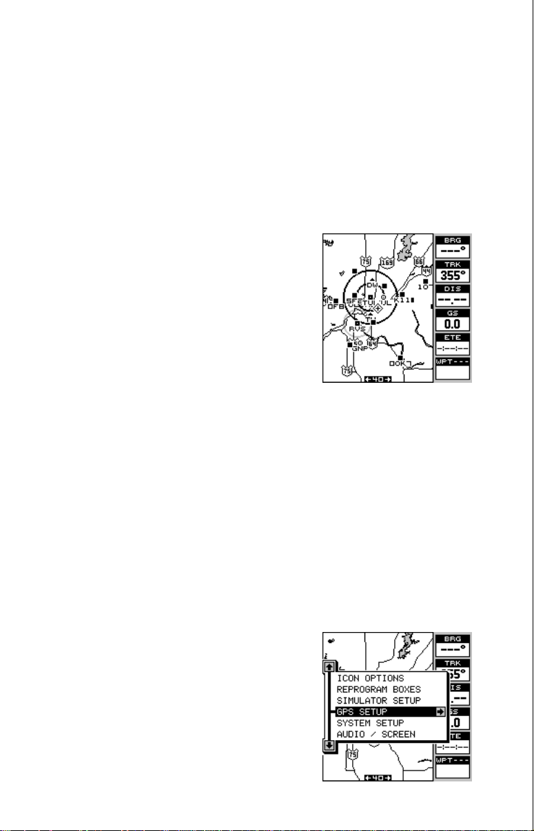
to erase the message. A screen similar to the one at right appears.
This is Map 3. Your present position is shown
as a cross surrounded by a diamond. As you
wait for the AirMap to find y our position, y ou’ll
see numbers flashing on the display. Anytime
you see flashing numbers, it means the AirMap does not have a position! Do not rely on
any data that is flashing! When the numbers
stop flashing, the unit has locked on to the satellites and the position is good.
That’s all y ou have to do to find y our position. The time displa y may not be
correct when the cold start method is used. See the manual initialization
section for details on changing the time.
Finding Y our Position
Initialization
A cold-start as described above can take up to 5 minutes to find your
position. There is another method to initialize the AirMap that may let it
acquire the satellites faster. Manually entering your position, local time
and date will help the GPS receiver determine which satellites are available and lock on to them f aster. There are two wa ys to input your position.
You can locate your position on the receiver’s map or enter your latitude
and longitude. Remember, once the receiver finds its position, it stores
the position into memory. The receiver won’t
have to initialized the next time you it on.
Enter by Map
To show the receiver your approximate location on its map, first press the MENU ke y , then
the up or down arrow keys until the “GPS
SETUP” menu is highlighted as sho wn at right.
Now press the right arrow key. The screen
shown at the top of the next page appears .
11
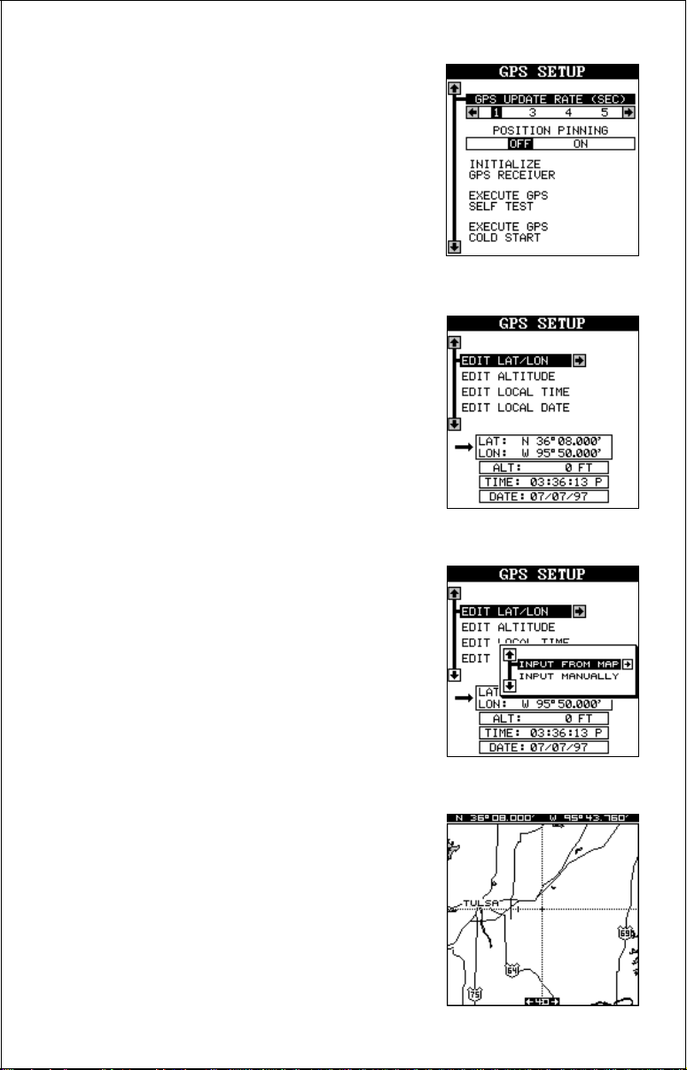
Using the down arrow key, highlight the “Initialize GPS Receiver” menu, then press the
right arrow key. The screen shown below appears next.
This is the GPS initialization screen. The position, altitude, time, and date the GPS receiver
is currently using to find the satellites is shown
at the bottom of this screen. Changing these
values to your local position and time will speed
the position lock.
T o change the position, highlight the “EDIT LA T/
LON label, then press the right arrow key. A
screen similar to the one at right appears. With
the “INPUT FROM MAP” label highlighted,
press the right arrow key. The screen below
appears.
The mapping screen appears with two lines
that intersect at the center. These lines are the
cursor. Using the arrow keys, mov e the cursor
to your present position. You can use the Z-IN
and Z-OUT keys to zoom in or out to find y our
area on the map. Once you have the cursor
close to your location, simply press the ENT
key. The unit returns to the GPS SETUP menu
with your local latitude and longitude showing
in the box at the bottom of the screen.
12
Enter Manually
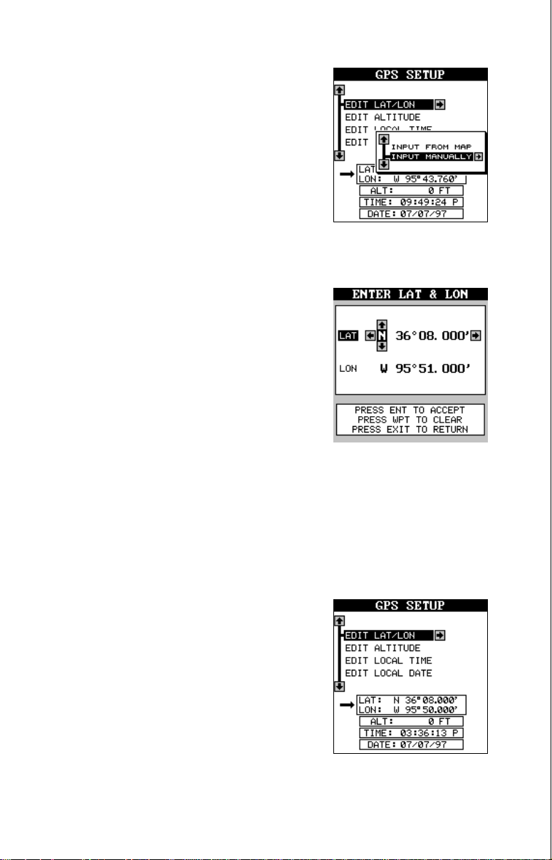
To change the position by manually entering
the latitude and longitude, press the MENU key,
then highlight the “GPS SETUP” label and
press the right arrow key. Now press right arrow key again while the “EDIT LAT/LON” box
is highlighted. The screen shown at right appears. Highlight the “INPUT MANU ALLY” label
and press the right arrow key. The screen
shown below appears.
If your latitude is south, press the up or down arrow k ey to change it. If it is
north, press the right arrow key to highlight the first number in the latitude.
Now press the up arrow key to increase the
number or the down arrow ke y to decrease it.
Once the first number in the latitude is set,
press the right arrow key once to mo v e to the
next number in the latitude.
Keep pressing the arrow k eys until the latitude
and longitude are set to your local position.
(Note: This position does not have to be very
accurate. If you can get it within one degree of
your actual position, that will be fine.) When it’s set, press the ENT key.
The AirMap accepts your entry and returns to the GPS setup menu.
Now change the local time and date if they’re incorrect on this screen by
highlighting the appropriate label and pressing the right arrow key. (Don’t
worry about altitude.) When ev erything is acceptable, press the EXIT ke y
to return to a mode screen. The AirMap will instantly use the data you
entered to find the satellites in the sky. (The
unit knows which satellites will be availab le at
the position, date, and time you entered. Therefore, it will only look for those satellites, making the search time much shorter than a cold
start which looks for all of the satellites until it
finds three.)
Once the AirMap finds and locks on to three
satellites, it stops flashing the numbers on the
display. (Note: Altitude will still flash until the
unit locks on to the fourth satellite. It takes four satellites to determine
altitude.)
13
IMPORTANT!
If the data shown in digital numbers on any screen is flashing, it means
that data is invalid. DO NOT RELY ON ANY NUMBERS THA T ARE FLASHING! Usually , this happens when the GPS receiver has lost its loc k on the
satellites. The data that is flashing was the last kno wn when the unit lost
its navigational capability .
DO NOT NAVIGATE WITH THIS UNIT UNTIL THE DATA STOPS
FLASHING!
POSITION/NA VIGA TION DISPLAYS
The AirMap has navigation, mapping, and windows group modes . These
screens were designed to show data that is used most often. Many of the
navigation, mapping, and windows screens can be customized to show
data other than the ones chosen by the factory . See the Reprogram Groups
section for more details.
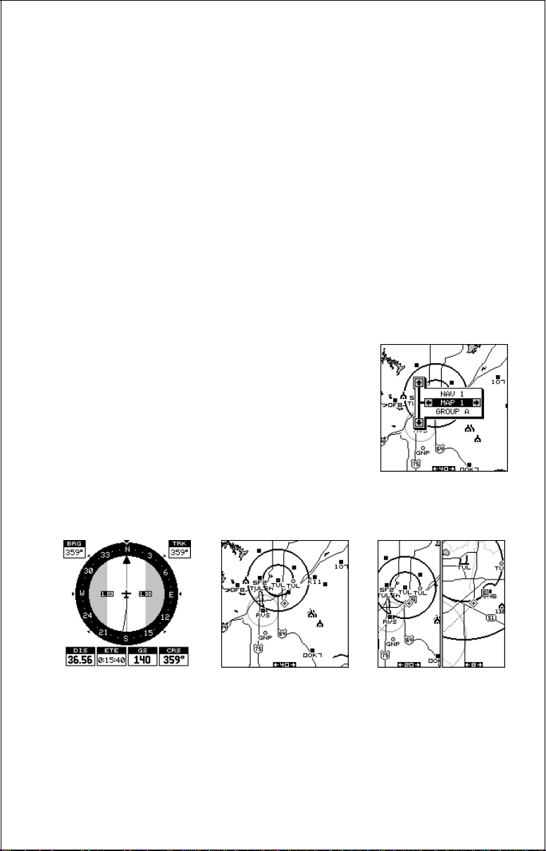
The three default displays are shown below. To
change displays, simply press the PAGES key. A
screen similar to the one at right appears. Now
press the up or down arrow keys to change modes .
(The windows display is shown as "Groups". For
example, Group A is the first windows group on
the PAGES menu.) Press the right arrow key to
see more screens on each mode. When the desired screen appears, press the EXIT key to clear
the menu.
NAVIGATION
(Nav 1)
MAPPING
(Map 1)
WINDOWS
(Group A)
Note: F or a list of abbre viations used on the displays, see the bac k of this
manual.
14
Navigation Screens
There are two navigation screens. Nav screen number one sho ws a graphical view of your trip , the other screen shows all navigation details in large
digital numbers.
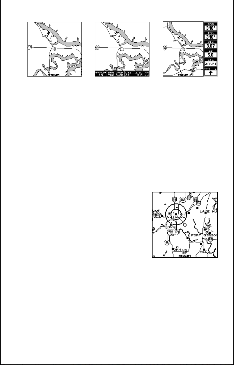
Nav Screen #1
This screen is dominated by a compass rose.
Your track (direction of travel) is indicated by
an arrow pointing down toward the compass
rose at the top center of the screen. Track is
also shown in the upper right corner of the display under the “TRK” label. In the example
screen shown at right, the track is 7°. The line
extending behind the arrow in the center show s
your track history.
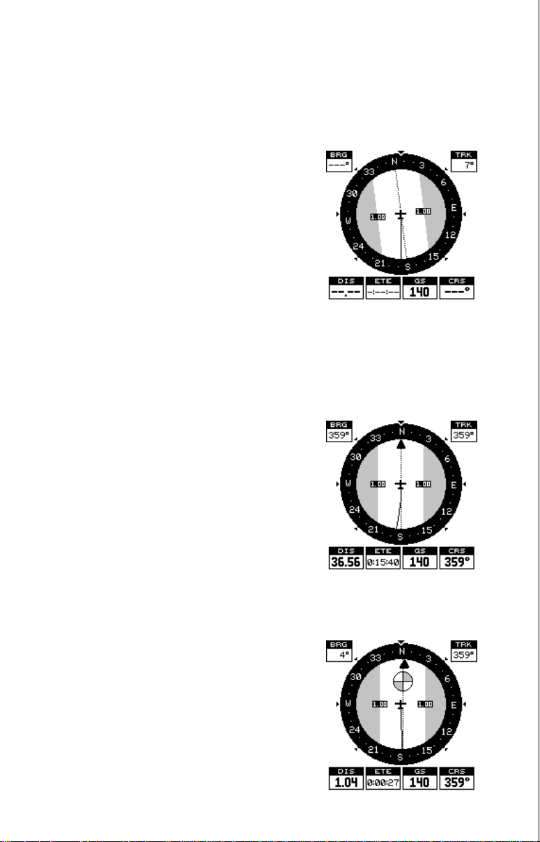
Your speed over ground or Ground Speed is shown at the bottom of this
screen. In this e xample, the ground speed is 140 knots. The screen looks
like this when you’ re not na vigating to a wa ypoint. (See page 58 f or inf ormation on waypoint navigation.) If y ou navigate to a wa ypoint, the screen
looks like the one below.
The bearing to the destination waypoint is
shown in the upper left corner of the screen.
Bearing is also shown by the large arrow pointing up to the compass.
The numbers on either side of the center arrow show the cross track error range . In other
words, (using the screen at right as an example) if the arrow crosses the dark band on
either side, you are one mile to the left or right
of the desired course.
A circle depicting your destination appears on
the screen as you approach the waypoint, as
shown here.
The digital boxes at the bottom of the screen
show (from left to right) your distance to go to
the destination (DIS), estimated time en route
(ETE), ground speed (GS), and course (CRS).
Course (CRS) is the bearing from your starting location to your destination. (Remember,
15
course has nothing to do with your present position, except f or your starting location.) It’s shown as a dotted line on the NAV 1 display. This is
shown as a reminder so that if you de viate from your original course, y ou
can easily return to it. (A “course” is a proposed path over the ground. A
“track” is y our actual path over ground.)
All of the digital boxes on this screen are programmable. See the “Programming” section f or more inf ormation.
Nav Screen #2
The navigation screen shows navigation inf ormation in large digital numbers. To vie w this screen, press the PAGES k e y, then press the up arrow
key until the black box surrounds the “NAV 1” label. Now press the right
arrow key. A screen similar to the one belo w appears. Press the EXIT key
to erase the menu.
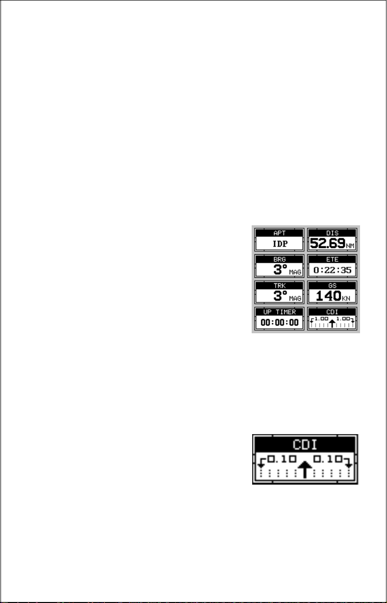
This screen is composed of eight digital display box es, including track (TRK), and g round
speed (GS). The destination shows in the upper left corner. Other boxes show navigation
data when a waypoint is recalled, including
bearing to the waypoint (BRG), distance to
waypoint (DIS), and estimated time en route
(ETE). The CDI is a course de viation indicator,
showing your distance to the left or right of the
desired course.
You can reprogram all of the digital box es on the NAV 2 screen. See the
"Programming" section for more inf ormation.
COURSE DEVIATION INDICAT OR (CDI)
The CDI shows your distance to the left or right
of the desired course to a waypoint. (In order
to use the CDI, you must first recall a w aypoint
or route. See the Navigation section for more
details.) The arrow in the center of the box
shows the direction to the destination. For example, if you’re travelling
straight towards the waypoint, the arrow points straight up. If you turn to
the right, the arrow points to the left, showing that the destination is to
your left.
16
The smaller arrows pointing down on each side
show the CDI’ s range. The def ault is 1/10 mile.
The small vertical bar shows the distance off
course and represents the course line. If the
bar moves to the right, then you are to the left
of the desired course line, and vice-versa. The CDI indicator shown above
shows that we are about .02 miles to the left of the desired course. (With
the CDI range of .10 miles, each vertical dotted line represents .02 mile.)
You can adjust the CDI’s range through the “Alarms/CDI” men u.
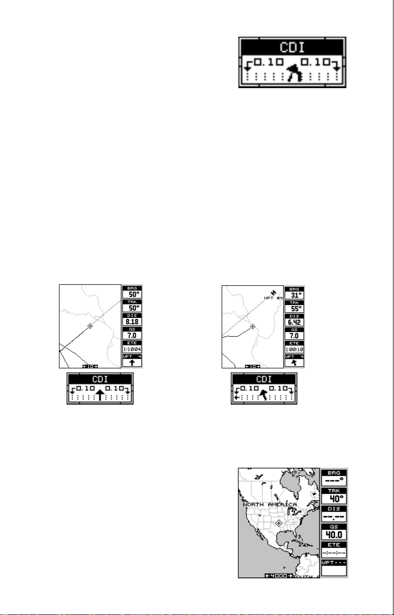
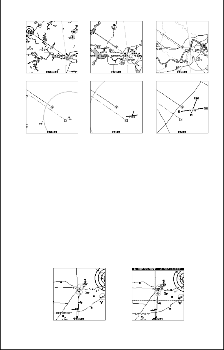
Using the CDI with a mapping screen helps you visualize your position in
relation to the course. The screen belo w left shows that we are on course.
The CDI arrow is pointing straight ahead and no off-course bar is showing. Looking at the screen on the right, howe v er , y ou can see that we are
off course to the right. In f act, w e are so far off course that we exceeded
the range of the CDI. The vertical bar has gone off the scale on the left
side of the CDI. A small arrow points to the left, showing the direction to
the desired course line. The CDI gives you a quick, easy to read visual
indicator of your relationship between your direction of tra v el and the desired direction.
Mapping
The AirMap has a ground map of the world built inside. This map has the
majority of its detail in far southern Canada, the continental United States
and Hawaiian islands, northern Mexico, the
Bahamas, and Bermuda. The background map
shows when the AirMap is first turned on, with
or without a map cartridge.
With the Jeppesen® cartridge plugged in, a
complete aviation database is activated. Airports, NDBs, V ORs , and other airspace information (including obstructions) are overlaid
onto the ground map.
17
MAP 1 MAP 2 MAP 3
There are three different mapping screens av ailable. Map screen number
3 shows by default, as sho wn at right. Your current position displa ys at the
center of the screen by a cross surrounded by a flashing diamond.
To view the other mapping screens, press the PAGES key. Press the up
or down arrow key to highlight the "MAP 1" label. Now press the right or
left arrow key to select a diff erent mapping screen. Press the EXIT k ey to
erase the pages menu.
Maps 2 and 3 (as shown above) have navigation data displayed using
digital numbers. The digital displays on map 3 can be rearranged or
changed to other displays. See the “Reprogram Boxes” section for more
information.
As you move , the map slides past your present
position, which always remains at the center
of the screen. The line extending from your
position shows the path you’ve tak en.
Use the Z-OUT and Z-IN keys to enlarge or
reduce the mapping area. If you have an IMS
SmartMap™ cartridge installed, it’s detail typically begins showing when you zoom in to the
10 mile range.
Jeppesen™ data shows at all zoom ranges, however, Lowrance® has a
unique method of displaying this data. If you were to turn on all airports,
VORs , NDBs, and controlled airspaces at the same time without filtering
the data, the map screen would become so cluttered that it would be
useless. The AirMap turns off virtually all aviation data at large ranges,
selectively turning on more data as you zoom in closer to your present
position or cursor location. See the two screens at the top of the next
page. The first one’s range is 150 NM and shows little aviation data. The
second screen is zoomed in to the 30 NM range and now shows much
more detail around the present position.
18

AUTOZOOM
Generally, when you travel using a mapping receiv er like the AirMap , you
spend some amount of time zooming in and out, looking at detail or the
whole route between the start and destination.
(Note: The autozoom feature does not work with C-Map cartridges.)
The AirMap has an autozoom feature that eliminates m uch of the button
pushing that competitive units force y ou to make. It works in conjunction
with the navigation feature. First you must recall a waypoint. (See the
waypoint section f or more information on navigating to a wa ypoint.) When
you turn the autozoom mode on, the AirMap zooms in on your present
position. As you travel towards the destination (recalled waypoint), the
AirMap begins zooming out, showing more of your course to the waypoint. After you cross the halfway point to your destination, the AirMap
zooms in closer , one zoom range at a time, keeping the destination on the
screen. Nearly every time it zooms in, you can see more detail. This is a
benefit for two reasons. Number one , you w ant to see more detail as you
get closer to the destination, especially if you’ve ne ver been there before .
T w o, it takes a load (small, perhaps , but still another thing to keep trac k of)
while you’ re occupied with other details .
The screens at the top of the next page show a slice of the progression of
a trip on an area lake. Screen number one is the start and is on the 1 mile
range. Intermediate stages progressively zoom out, until you’ re at the midway point. The AirMap then begins zooming in as you get closer to the
destination.
19
To use the autozoom feature, first set the AirMap up to navigate to a
waypoint. (See the Navigation section f or more details.) Next, simply press
the MENU key, then use the up or down arrow keys to highlight the
“AUT OZOOM OFF/ON” menu. Press the right arrow ke y to turn it on, the
left to turn it off.
Map Cursor
Pressing an arrow key while a map is on shows two dotted lines that
intersect at your present position. These dotted lines are called a “cursor”
and have a v ariety of uses.
You can move the cursor around the display b y pressing the arrow ke ys in
the direction you want it to move. This lets you view different areas of a
map, away from your present position. When it’s turned on, the zoom-in
and zoom-out keys w ork from the cursor’s position - not the present position, so you can zoom in on any detail, anywhere while na vigating.
CURSOR OFF
CURSOR ON
20
The latitude/longitude of the cursor shows in the box at the top of the
screen whenever the cursor is activated. The map cursor is also used to
place and erase icons and waypoints .
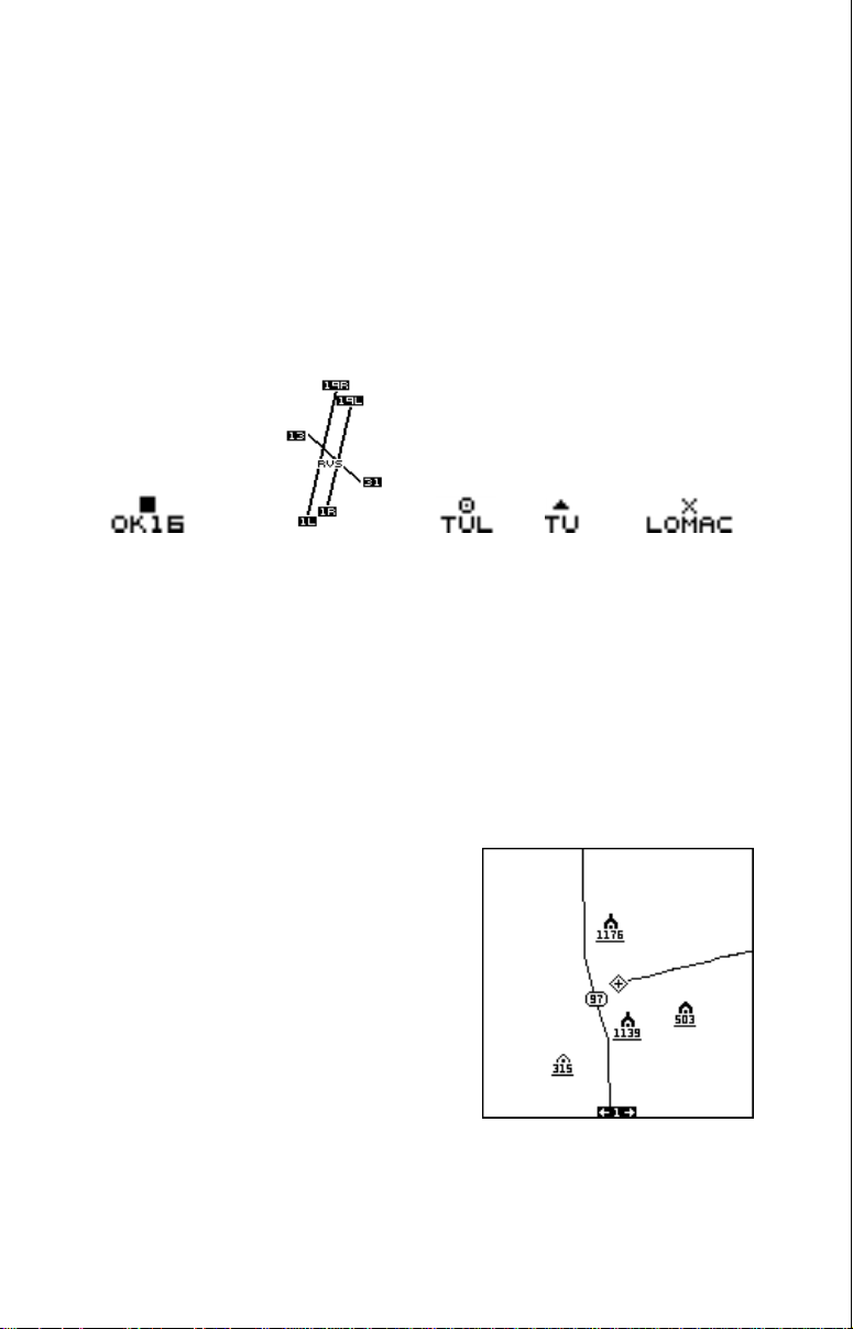
MAP SYMBOLS
Airports, VORs, NDBs, and Intersections
All airpor ts are shown as a square with its identifier beneath it. Larger
airpor ts are shown the same way until you zoom in closer, then their
runways become visible. Zoom in farther, and the runway numbers also
appear. VOR’ s are shown as a circle with a dot inside, while NDB’ s hav e a
triangle. Intersections are depicted as an “X”.
AIRPORT WITH
SMALL RUNWAY(S)
AIRPORT WITH
LARGE RUNWAY(S)
VOR NDB INTERSECTION
Obstructions
Your Airmap has obstruction capability. The database cartridge installed
in your unit lets you see ground obstructions on the map displa y such as
radio and television towers . This information is included in the Jeppesen
cartridge, so you don't need two cartridges for a viation data.
The obstruction portion of the database
cartridge covers all of the continental
United States, Alaska, and parts of
Canada, Mexico , and Bahamas.
On the screen shown at right, four obstructions are shown. Three different symbols
are used to show them, depending on their
height. The y are:
®
21
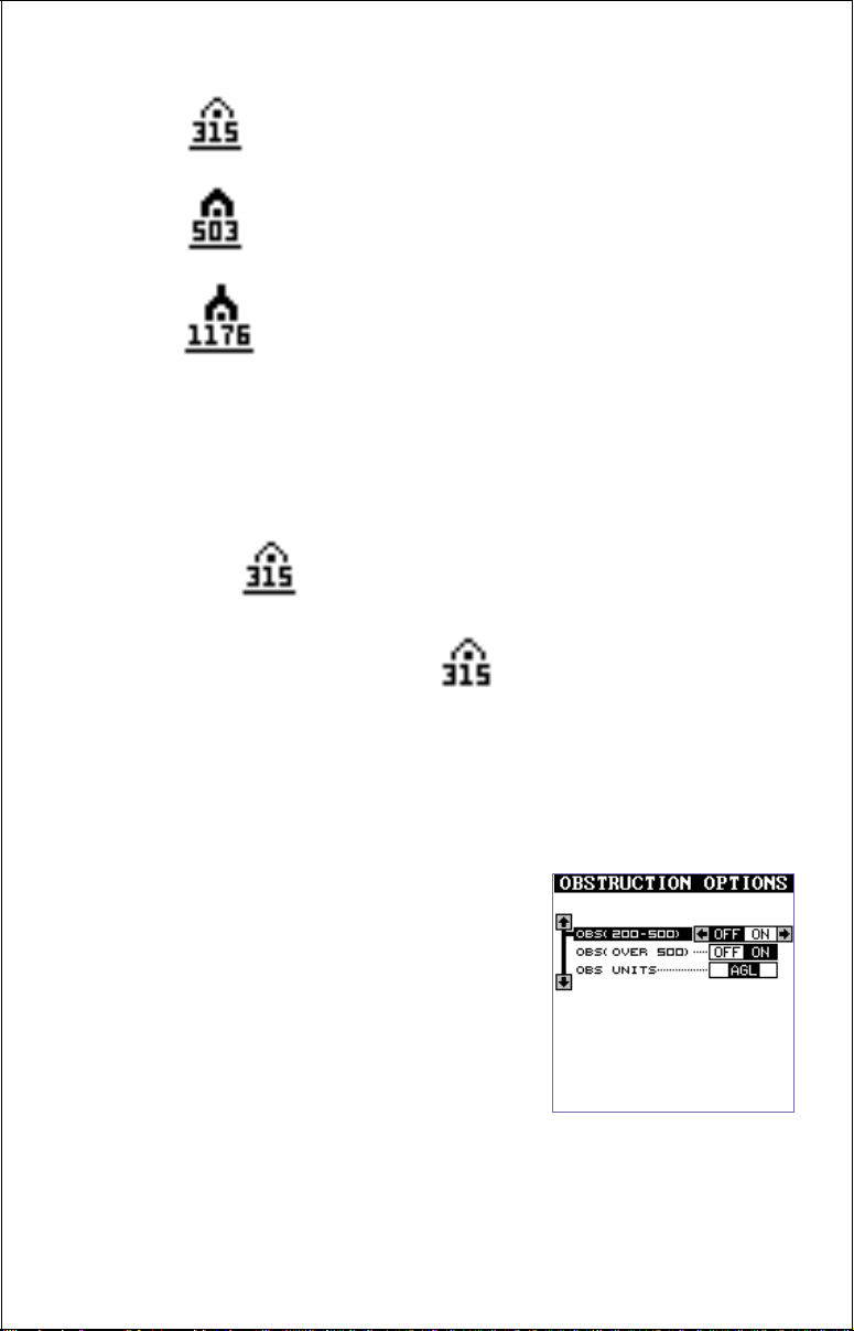
SMALL - 205 to 499 feet
MEDIUM - 500 to 999 feet
LARGE - 1000 feet and abov e
The elevation shows beneath the symbol. If a line is beneath the elevation, then the height is AGL, or above ground level. If no line shows beneath the height, then it is MSL or above mean sea le v el.
For e xample, this obstruction is
315 feet AGL:
This obstructions is 315 feet MSL:
Typically, you'll need to zoom in to a range of 40 miles to see the large
obstruction symbols, and smaller ranges to see the larger obstruction's
height and smaller obstructions. To view smaller obstruction's height, you
may need to zoom in to the 5 mile range .
You can turn the obstructions on or off and
switch from AGL to MSL by highlighting the
"OBSTRUCTIONS" label on the "Air Map
Options" menu, then pressing the right arrow
key. The obstruction menu appears as shown
at right. The AirMap defaults are: obstructions
from 205 to 499 feet (shown as 200-500 on
the menu) off and obstructions 500 feet and
above on. AGL defaults on, also. You can
change any of these by highlighting the desired menu, then pressing the left or right arrow keys.
22
Airspace
The AirMap can show the following airspaces: Class B and C airspace,
control zones, control areas (CTA), Terminal Control Areas (TMA), prohibited, restricted, MOA’s (including tr aining, danger, and caution areas),
and alert areas.
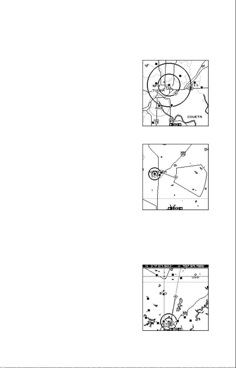
In this example, the Class C airspace surrounding Tulsa International airport (TUL) is clearly
visible as two dark circles. The control zone
airspace around Richard Jones (Riverside) airport (RVS) is shown in gra y.
This screen shows the Eureka MOA east of
Wichita, Kansas on the 100 nautical mile range.
The airspace defaults for the AirMap are as
follows: Class B, C, D, Prohibited, Restricted,
and MOA’ s are on. All other airspaces default
off. An airspace alarm can be set that will warn
you of any of the abov e airspaces are within a preset radius of your position. Another airspace alarm will “look-ahead” and tell you how soon you
will cross into an airspace. See the alarms section fro more information.
Airspace Information
The AirMap lets you identify an airspace without physically entering it by using the cursor.
To do this, press any arrow key while a map is
showing. In this example, we’re using Map 1.
The cursor appears. Now move the cursor to
the desired airspace as shown at right. (Note:
You may have to zoom-in and/or zoom-out to
view the airspace.)
23
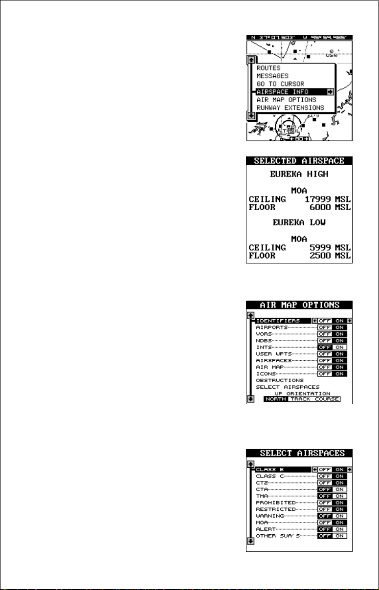
With the cursor moved to the airspace, press
the MENU key. A screen similar to the one at
right appears.
Now highlight the “Airspace Info” label and
press the right arrow key. A message screen
appears as shown below.
This is the information for the airspace that the
cursor is resting on. To view information about
another airspace, simply move the cursor to
that airspace and repeat these steps. To erase
this screen, simply press the EXIT key.
Air Map Options
You can select the aviation symbols and airspaces that you want displa yed on the screen.
T o do this, first press the MENU k ey , then press
the up or down arrow keys until the black box
is on the “AIR MAP OPTIONS” label. Press
the right arrow key to select it. A screen similar to the one at right appears.
Use the up and down arrow ke ys to mo v e the
box to the desired symbol, then press the right
arrow key to turn it on or the left arrow k e y to turn it off.
Note: You can’t turn off restricted or
prohibited airspaces.
To change the airspace selections, press the
down arrow key until the “Select Airspaces”
label is highlighted, then press the right arrow
key. The screen shown at right appears.
24
 Loading...