

Page 1

®
AirMap 100
INSTALLATION AND
OPERATION INSTRUCTIONS
®
Page 2

Copyright © 1996, 1997, 1998 Lowrance Electronics, Inc.
All rights reserved.
AirMap™ 100 is a trademark of Lowrance Avionics .
Lowrance® is a registered trademark of Lowrance Electronics, Inc.
Jeppesen® is a registered trademark of Jeppesen Sanderson, Inc.
WARNING!
USE THIS UNIT ONLY AS AN AID T O NA VIGA TION. A CAREFUL NA VIGATOR NEVER RELIES ON ONLY ONE METHOD TO OBTAIN POSITION INFORMA TION.
Never use this product while operating a vehicle.
The background map built into this unit is not intended f or navigation and
its accuracy has not been verified. This map is deriv ed from U .S. government sources which rely on ground and aerial surveys and satellite data.
Since there can be inaccuracies in the data used to create the maps and
in the map’s resolution, plus position inaccuracies in the navigation system, use caution when using this product.
CAUTION
When showing navigation data to a position (wa ypoint), this unit will show
the shortest, most direct path to the waypoint. It pro vides navigation data
to the waypoint regardless of obstructions. Therefore , the prudent navigator will not only take advantage of all a vailable na vigation tools when travelling to a waypoint, but will also visually check to make certain a clear,
safe path to the wa ypoint is alw ays available.
The operating and storage temperature for y our unit is from -4 degrees to
+167 degrees Fahrenheit (-20 to +75 deg rees Celsius). Extended storage
temperatures higher or lower than specified will cause the liquid crystal
display to fail. Neither this type of failure nor its consequences are covered by the warranty. F or more inf ormation, consult the factory customer
service department.
All features and specifications subject to change without notice.
Lowrance Avionics may find it necessary to change or end our policies,
regulations, and special offers at any time . We reserve the right to do so
without notice.
All screens in this manual are simulated.
Page 3

This device complies with P art 15 of the FCC Rules. Oper ation is subject
to the following two conditions: (1) this device may not cause harmful
interference, and (2) this device must accept any interference received,
including interference that may cause undesired oper ation.
Note:
This equipment has been tested and found to comply with the limits for a
Class B digital device, pursuant to P art 15 of the FCC Rules. These limits
are designed to provide reasonable protection against harmful interference in a residential installation. This equipment generates, uses and can
radiate radio frequency energy and, if not installed and used in accordance with the instructions, may cause harmful interference to radio communications. How ever , there is no guarantee that interf erence will not occur in a particular installation. If this equipment does cause harmful interference to radio or television reception, which can be determined by turning the equipment off and on, the user is encouraged to try to correct the
interference by one or more of the f ollo wing measures:
• Reorient or relocate the receiving antenna.
• Increase the separation between the equipment and receiver.
• Connect the equipment into an outlet on a circuit different from that to
which the receiver is connected.
• Consult the factory customer service department for help.
Specifications
Dimensions................................................. 6.75” L x 2.25” W x 1.625” D
Display.................................................................. 160 H x 104 W pix els
P o w er ....................................................................................... 5-35 vdc
Waypoints.........................................................................................750
Routes ................................................................................................9 9
Wa ypoints per Route (maximum)........................................................ 99
Total Wa ypoints used in Routes......................................................1500
Icons............................................................................................... 1000
Sava ble Plot Trails.................................................................................3
Maximum Plot Trail P oints..................................................3000 per trail
Page 4

DEFINITION OF TERMS/ABBREVIATIONS
Due to space considerations, the digital displays use abbreviations for
some names. They are as follows:
ALT ............... Altitude
BRG ............. Bearing - The direction from your present position to a
waypoint.
CDI ............... Course Deviation Indicator - Shows your distance to the
side of the desired course line.
CLOCK......... Your local time.
TRK .............. T r ack - The direction you’re trav elling.
DIS ............... Distance - Distance remaining between your present po-
sition and a waypoint.
DNT/UPT...... Countdown timer (DNT) and Count up timer (UPT)
ETA............... Estimated Time of Arrival
ETE .............. Estimated Time En route
ICON ............ A symbol you can place on the map, representing a land-
mark.
POSITION .... Your present position.
GS ................ Ground Speed - Your actual speed.
UTC.............. Coordinated Universal Time - Time at the prime meridian
at Greenwich, England. Formerly known as GMT.
VOLTS .......... Electrical system voltage.
VMG ............. Velocity Made Good - Your ground speed towards a re-
called waypoint, airport, etc.
Page 5

INTRODUCTION ............................................................................................................1
SA - What is it? ........................................................................................................2
Don’t Get Lost ..........................................................................................................2
GETTING STA RTED ......................................................................................................3
Power ................................................................................................................. 3
BATTERIES ..............................................................................................................3
Battery Installation .............................................................................................3
NiMH Battery .....................................................................................................3
External Antenna ..................................................................................................... 4
Yoke Mount ..............................................................................................................5
OPERATION ................................................................................................................. 6
Turning Power On ....................................................................................................6
Satellite Status Screen ............................................................................................6
Finding Y our Position................................................................................................8
Auto Search.......................................................................................................8
Manual Initialization........................................................................................... 8
Position Acquisition ........................................................................................... 9
POSITION/NAVIGATION SCREENS ......................................................................9
Navigation Screens ...........................................................................................10
Course Deviation Indicator (CDI)................................................................11
Map ................................................................................................................. 12
Cursor .........................................................................................................14
Map Symbols ..............................................................................................14
Obstructions................................................................................................ 15
Airspace ......................................................................................................16
Map Setup...................................................................................................18
Map Options ......................................................................................................18
Map Orientation .......................................................................................... 18
Autozoom ....................................................................................................20
View Destination .........................................................................................21
Range Rings/Grid Lines..............................................................................21
Earth Map Options ............................................................................................ 22
Earth Map On/Off .......................................................................................22
Text Labels ..................................................................................................22
Locations..................................................................................................... 22
Map Detail ...................................................................................................22
Gray Fill.......................................................................................................23
Map Boundaries ..........................................................................................24
Air Map Options.................................................................................................24
Runway Extensions ....................................................................................25
Plot Trail Options ...............................................................................................26
Clear Trail ....................................................................................................26
Flash Trail ....................................................................................................26
Update Options ...........................................................................................26
Save Trail .................................................................................................26
Show Trail.................................................................................................27
ICONS ...............................................................................................................27
MAP DOWNLOADING ...................................................................................... 29
WINDOWS.........................................................................................................31
Reprogram Window Groups .......................................................................36
Reprogram Boxes ....................................................................................... 37
RESET GROUPS ..............................................................................................38
DATABASES...................................................................................................... 38
Aviation Database.......................................................................................38
User Database - Waypoints ........................................................................42
Page 6

WAYPOINTS......................................................................................................42
Waypoint Menu ...........................................................................................42
Saving Your Present Position as a Waypoint (Quick Save Method)...........42
Saving The Cursor Position as a Waypoint ................................................43
Saving Your Present Position as a Waypoint (Select Number Method) .....43
Saving a New Position ................................................................................44
Waypoint Averaging .................................................................................... 44
Project a Waypoint ......................................................................................45
Selecting a Waypoint .................................................................................. 46
Editing a Waypoint ......................................................................................46
NAVIGATION............................................................................................................47
Navigating to a cursor location..........................................................................47
Navigating to a Waypoint using the Map...........................................................48
OTHER WAYPOINT OPTIONS .........................................................................49
Move a Waypoint.........................................................................................49
Delete a Waypoint .......................................................................................49
Delete All Waypoints ...................................................................................49
“Nearest” Feature........................................................................................50
ROUTES ................................................................................................................. 51
Create a Route ..................................................................................................51
Delete a Waypoint from Route .......................................................................... 53
Waypoint Statistics ............................................................................................ 53
Following a Route..............................................................................................53
Waypoint Information ..................................................................................54
Delete a Route...................................................................................................55
CANCEL NAVIGATION ............................................................................................55
Navigation Notes......................................................................................................55
SYSTEM SETUP .....................................................................................................56
Sound ................................................................................................................ 56
Contrast .............................................................................................................56
Set Local Time...................................................................................................57
Units of Measure ...............................................................................................57
NMEA / DGPS ...................................................................................................57
NMEA Output ....................................................................................................58
DGPS.................................................................................................................58
Serial Communication Setup.............................................................................59
Reset Options.................................................................................................... 60
Reset Groups .................................................................................................... 61
System Info ........................................................................................................ 61
GPS SETUP ............................................................................................................61
Power Save........................................................................................................ 60
Position Format .................................................................................................60
DATUM............................................................................................................... 62
PCF (Position Correction Factor) ......................................................................63
POSITION PINNING ......................................................................................... 64
ALARMS ................................................................................................................. 65
SUNRISE/SET MOONRISE/SET CALCULATOR ...................................................67
SIMULATOR .............................................................................................................67
E6B COMPUTER.....................................................................................................68
AVIATION DATA DOWNLOAD.................................................................................71
JEPPESEN® DATABASE UPGRADE.....................................................................73
DATUM LIST ............................................................................................................74
UPS RETURN SERVICE.........................................................................................79
WARRANTY.............................................................................................................81
DATABASE LICENSE AGREEMENT ......................................................................82
DATABASE WARRANTY .........................................................................................83
Page 7

INTRODUCTION
Thank you for purchasing a Lowr ance Avionics AirMap 100. With its large
LCD screen, easy to use menus, and outstanding performance, we think
you’ll be happy with y our AirMap 100 f or man y y ears. No other handheld
GPS receiver on the market today has the AirMap’s combination of 12
channel receiver , Jeppesen® database with obstacles (U.S. only), ground
and hydrographic mapping capability, and programmable screens in a
handheld unit.
The Global Positioning System (GPS) w as developed by the United States
Department of Defense as a 24-hour a day, 365 days a year global navigation system for the military . Civilian availability was added (b ut with less
accuracy) using the same satellites. T w enty-four satellites orbit the Earth.
Three of these satellites are spares, unused until needed. The rest virtually guarantee that at least four satellites are in vie w of anyplace on Earth
at all times.
The system requires three satellites in order to determine a position. This
is called a 2D fix. It takes four satellites to determine both position and
elevation, (y our height abov e sea le v el - also called altitude.) called a 3D
fix.
Remember, the unit must have a clear view of the satellites in order to
receiver their signals. Unlike radio or television, GPS works at very high
frequencies. The signals can be blocked easily by trees, buildings, even
your body. Fortunately, they do travel through glass and plastic, so your
receiver will work in the aircraft, if it has a clear view of the satellites
through the windshield or side windows. Let someone else dr ive if you
use it in a car or other vehicle.
Never use this GPS receiver while operating a vehicle!
The first time you use this unit, walk outside and turn it on in your backyard, an open field or park. Once it locks onto the satellites, you can experiment with it around buildings and trees. This will give you some idea
of its sensitivity to blockage.
Like most GPS receivers, this unit doesn’t have a compass or any other
navigation aid built inside. It relies solely on the signals from the satellites
to calculate a position. Speed, direction of travel, and distance are all
calculated from position information. Theref ore, in order for it to determine
direction of travel, you must be moving and the faster, the better. This is
not to say that it won’t work at walking speeds - it will. There will simply be
more “wandering” of the data sho wn on the displa y.
1
Page 8

SA - What is it?
Another factor that greatly influences the receiver’s ability to deter mine
position is SA. The United States government intentionally degrades the
satellites signal for civilian users. They introduce small errors into the
satellite’s signals that makes the GPS receiver less accurate. These errors are called selective av ailability , or SA. Ho w bad is it? The y guarantee
that the position reported by a GPS receiver that meets their specifications is within 100 meters horizontally and 150 meters vertically 95% of
the time. (The position can be better than that or worse than that the other
5% of the time.) In other words, the position shown on your receiver is
within 100 meters of your actual position, 95% of the time. That’s o ver 300
feet! Not exactly pinpoint accur acy, but then few people need positioning
accuracy greater than this. However, if you do want better performance,
(and who doesn’t?) many manufacturers (including Lo wrance) sell a DGPS
receiver that attaches to your GPS receiv er . The DGPS system transmits
correction signals that nullify the effects of SA. The DGPS receiver takes
signals from these land-based transmitters and gives them to the GPS
receiver which then uses them to show a more accurate position. The
ironic part is the federal government implemented SA and is also operating many DGPS transmitters. (You can use the signals from all of the
Coast Guard DGPS stations for free, b y the wa y.) The downside to this is
it requires another piece of electronic gear (the DGPS receiver) which
usually isn’t small enough to carry with you, but will work nicely on a
vehicle. And you ha ve to be close enough to a station to receive the DGPS
signals.
Don’t Get Lost
Generally, you find that using your GPS receiver without DGPS is both
easy and amazingly accurate. It’s easily the most accurate method of
electronic navigation available to the general public today. Remember,
however that this receiver is only a tool. Always have another method of
navigation available, such as a chart or map and a compass. It’s a good
idea to carry spare batteries with you, especially if you’re venturing into
unknown territory .
Also remember that this unit will always show navigation information in
the shortest line from your present position to a waypoint, regardless of
terrain! It only calculates position, it can’t know what’s between you and
your camp, f or example. It’ s up to you to saf ely navigate around obstacles,
no matter how you’re using this product.
2
Page 9
GETTING STARTED
Po wer
The AirMap 100 operates from AA batteries, a DURACELL® NiMH rechargeable battery, or from 5 to 35 volts DC using the external power
cable. If the power cable is used, the AirMap 100 automatically switches
to it if the external power is greater than the battery voltage. If for any
reason the external power fails, the unit automatically switches to the
batteries.
BATTERIES
The unit requires four AA batteries. W e recommend you use alkaline batteries for the best trade-off between battery life and cost. However, you
can use nickel-cadmium (ni-cad), or lithium batteries. You can also use
rechargeable alkaline batteries such as RayOVac® Renewals®. With the
exception of lithium, none of the abov e batteries will last as long as standard alkaline batteries. We recommend DURACELL® brand, but others
will work. Do not use “heavy-duty” batteries or any type other than the
ones listed above. Do not mix different types of batteries. (For example,
don’t use both alkaline and ni-cad batteries at the same time.)
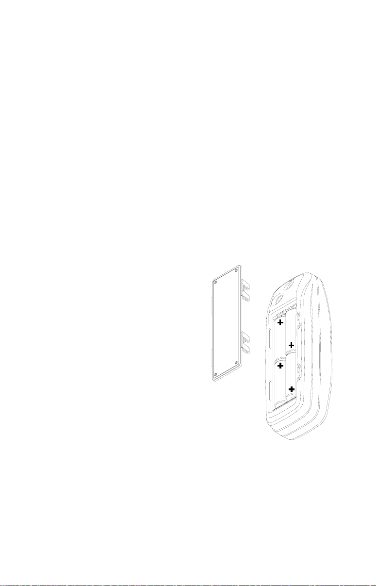
Battery Installation
First turn the unit so that its back is facing
you. Push the two tabs to the left and remove the battery cover as shown at right.
Install the batteries according to this diagram. (There’s a decal in the battery compartment showing the correct polarity,
also.) Replace the battery compartment
cover and the unit is ready f or use.
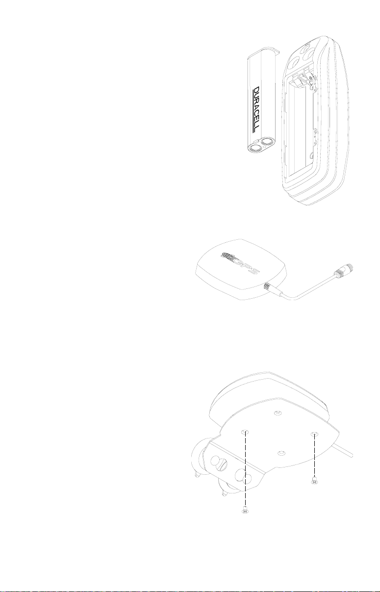
NiMH Battery
The DURACELL® DR-121 nickel-metal
hydride (NiMH) battery replaces the four
standard batteries. It is sold as an accessory , model BR-1 which includes a charger
custom designed for the DR-121. The battery never needs to be remo ved
from the unit, since the charger connects to the GPS receiver and charges
the DR-121. You can even use the receiv er while the battery is charging!
To install the NiMH battery, remove the battery cover and place the battery into the compartment as shown on the next page. It will only fit one
way, so if it’s difficult to install, simply turn it over and drop it into place.
Replace the compartment cover and follow the charging instructions included with the BR-1.
3
Page 10
(Note: The DR-121 is the only batter y that
can be recharged in this unit! Using the external power cable alone does not charge the
battery! You must use a charger supplied by
Lowrance in order to charge the battery . Also,
this charger will only charge a DR-121. It will
not charge any other type of battery installed
in the unit, including ni-cads or rechargeable
alkallines.)
External Antenna
Although this GPS receiver is e xtremely sensitive, it can be used
in locations where the built-in antenna simply cannot receive signals from enough satellites. An e xternal antenna is supplied with your unit
to use when conditions warrant. Usually, it’s
best to use the external antenna when the unit is attached to the yoke
mount.
A second connector on the back
of the unit is for an external antenna. The external antenna included with your unit plugs directly into this connector.
To use the antenna, first assemble the bracket, antenna, and
suction cups as at right. Two screws are
provided to attach the bracket to the antenna.
4
Page 11
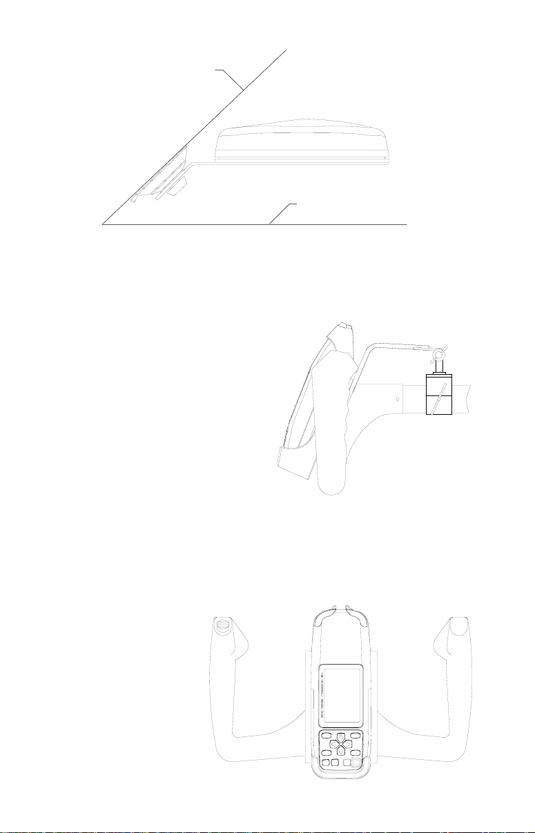
WINDSHIELD
DASH
Moisten the suction cups and press them firmly against the inside of the
windshield, away from y our line of sight. Route the antenna’ s cable to the
GPS receiver and it’s ready for use.
Y OKE MOUNTING
Included with your AirMap is a yoke
mounting bracket. It secures to the
yoke’s shaft with a clamp. Fasten the
cradle packed with your unit to the
yoke mount with four 2 mm screws.
Follow the instructions included with
the yoke mount to assemble and attach it to your aircraft. The AirMap simply snaps into the cradle.
The AirMap can operate from batteries or the external power cord when
it’s attached to the y oke mounting brack et. To use the external power cord,
simply plug one end into the power connector on the AirMap and the
other end into the aircraft’s cigarette lighter.
Some pilots like to keep
fresh batteries in their
units, even when using
the external power . If the
power fails, the unit will
automatically switch to
the batteries, thus keeping the unit on without
interruption.
5
Page 12
OPERATION
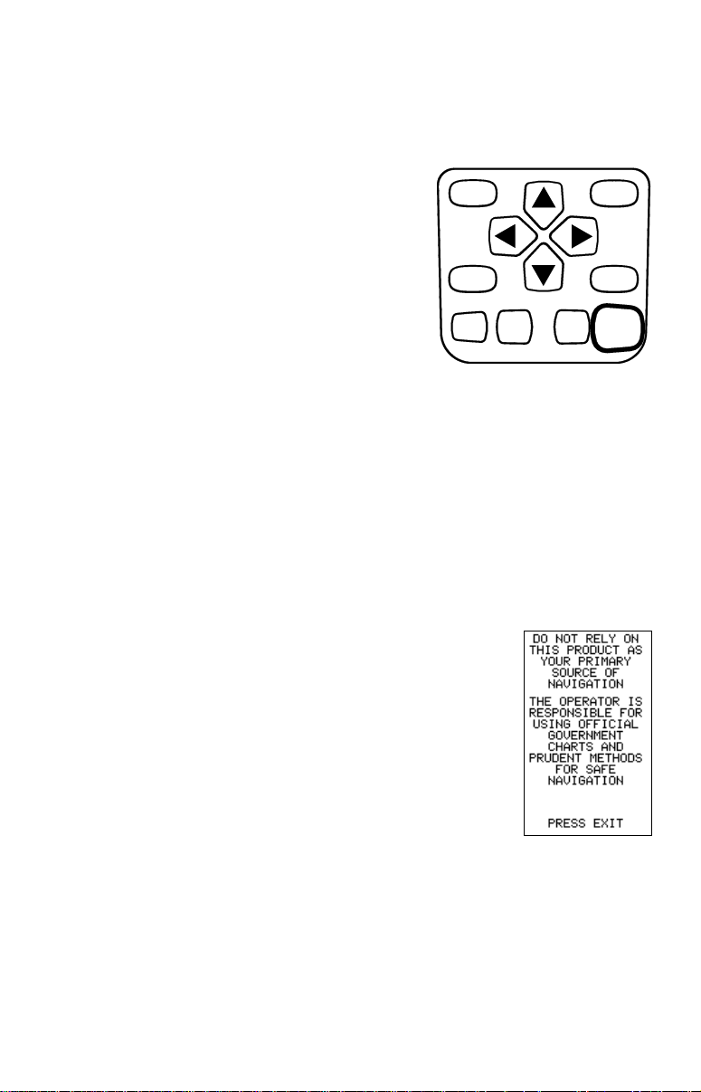
Keyboard
There are 12 keys on the keyboard. You navigate through the menus,
adjust the chart’s cursor, and enter data using the arrow keys. The five
major modes of operation are accessed
using the PAGES key. Press the MENU k ey
to select or adjust a feature from a list. The
Z-IN and Z-OUT keys zoom-in or z oom-out
the view on the plotter screen. The ENT and
EXIT keys are used to enter or clear data or
screens. Save and edit wa ypoints using the
WPT key. The PWR key turns the unit on
and off. Pressing it once while the unit is
operating turns on the screen’s backlight. T o
prevent an accidental shutdown, you must
hold the PWR key down for a few seconds in order to turn the unit off.
Menus
Most of the unit’s f eatures are f ound on “men us’. Y ou can view the men us
by pressing the MENU key. This product has “Intelligent Menus”. There
are many menus that pertain to only the map, for example. When you
press the MENU key and the plotter is sho wing, menu items for the plotter
show in addition to the normal menus. For e xample, if the navigation screen
is showing, and you press the MENU ke y, plotter menu items won’t show
on the list. This helps you find the needed item without scrolling through
unnecessary menus.
PAGES WPT
MENU EXIT
ZIN ENT
ZOUT
PWR
Turning Power On
To turn the unit on, simply press the PWR key. A GPS
logo screen appears, then the screen similar to the one
at right appears. Read the message on the screen,
then press the EXIT key to erase it or wait a few seconds and it automatically clears. The satellite status
screen shown at the top of the next page appears ne xt.
Satellite Status Screen
This screen shows a graphical view of the satellites that are in vie w . Each
satellite is shown on the circular chart relative to your position. The point
in the center of the chart is directly overhead. The small inner ring represents 45° above the horizon and the large ring represents the horizon.
North is at the top of the screen. You can use this to see which satellites
are obstructed by obstacles in your immediate area if you hold the unit
facing north.
6
Page 13

The GPS receiver is tracking satellites that are surrounded by a black box. If the satellite number is not
surrounded by a box, then the receiver hasn’t locked
onto that satellite and it isn’t being used to solve the
position.
Beneath the circular graph are the bar graphs, one f or
each satellite in view . Although the unit has twelv e channels, it dedicates one channel per visible satellite. Therefore, if only six satellites are visib le, only six bar charts show at the bottom
of the screen. The higher the bar on the graph, the better the unit is receiving the signals from the satellite.
The number in the upper left corner is the “expected horizontal position
error” or e xpected error from a benchmark location. In other words , if the
expected error shows 50 f eet, then the position sho wn by the unit is estimated to be within 50 feet of the actual location. Ho we v er , this n umber is
only valid if you’re using DGPS or if S/A is tur ned off. Due to S/A, the
accuracy can only be less than 100 meters, 95% of the time, per U.S.
government specifications. Although the expected error is not accurate
unless you hav e a DGPS receiv er, it does give you an indicator of the fix
quality the unit currently has. The smaller the expected error n umber , the
better (and more accurate) the fix is.
If the expected error is flashing, then the unit has not locked onto the
satellites, and the number shown is not v alid.
The fix indicator on the left center shows either 2D or 3D . A 2D fix means
the unit has locked onto three satellites and has calculated its position. A
3D fix means the unit has locked onto at least four satellites and has
calculated both the position and altitude. (Remember, it tak es three satellites to determine the position - four to determine position and altitude.) If
neither 2D nor 3D are showing, then the unit doesn’t hav e the position or
altitude.
A battery level indicator on the lower right side of the screen shows the
approximately how much life is in the batteries. This r uns from “F” (fully
charged) to “E” (e xpired).
A light bulb indicator at the top right corner of the screen appears when
the backlights are on.
7
Page 14

Finding Y our Position
Auto Search
To lock onto the satellites, the GPS receiver needs to know it’s current
position, local time, and date. (Elev ation (altitude) is also used in the equation, but it’ s rarely required to determine a position.) It needs this data so
that it can calculate which satellites should be in view . It then searches for
only those satellites. When your GPS receiver is turned on for the first
time, it doesn’t know what your position or elevation (altitude) is. It does
know the current UTC time and date since these were programmed into it
at the factory and an internal clock keeps the time while the unit is turned
off. It begins searching for the satellites using the above data that it acquired the last time it was turned on. This probably was at the Lowrance
factory. Since it’s almost certain that you’re not at the Lowrance factory,
it’s probab ly looking for the wrong satellites . If it doesn’t find the satellites
it’s looking f or after fiv e minutes, it s witches to A uto Search. The receiver
looks for any satellite in the sky. Due to advanced technology, the auto
search time has shrunk to about five minutes, so the longest time you
should ever ha ve to w ait is ten minutes from the time y ou turn the unit on
until it locks onto the satellites and shows a position. Once the unit loc ks
onto the satellites, it should take less than a minute to find your position
the next time it’s turned on, provided you haven’t moved more than approximately 100 miles from the last location it was used.
Manual Initialization
If you don’t want to wait for the Auto Search, then you may be able to
speed up the initialization process by using the manual initialization f eature. Using this feature tells the unit it’ s approximate position. Once it knows
it’s location, it determines exactly which satellites should be in view and
starts looking only for those satellites.
To manually initialize the unit, press the MENU key.
Now press the down arrow ke y until the “GPS SETUP”
label is highlighted. Press the right arrow k ey . The “INIT
GPS” (Initialize GPS) label is highlighted. Press the right
arrow key again. The screen at right appears. Use the
arrow keys to mo ve the crosshairs to your appro ximate
location on the map. You may use the ZOUT key to
zoom the map out. This will mak e it easier and faster to
find your location on the map. Once you have the
crosshairs on your location, press the ENT key. The
unit returns to the satellite status screen.
Using the manual initialization method loads a position that’s close to
yours into the GPS receiver. It should now have position, time , and date,
8
Page 15

thereby giving it the data it needs to determine which satellites are in
view . Once the satellites are known, the receiver searches for only those
satellites, making a lock f aster than an auto search method.
Position Acquisition
When the receiver locks onto the satellites and calculates a position, it
shows the message “Position Acquired” on the screen. All position and
navigation data flashes until the unit acquires a position.
any data that is flashing!
When the numbers are flashing, the y represent
Do not rely on
the last known values when the unit lost it’s lock on the satellites.
(Note: The altitude data may still flash even if the unit shows a “Position
Acquired” message and all other data is not flashing. The unit must be
locked onto at least f our satellites to determine altitude. It only tak es three
satellites to determine position. You can navigate with this unit if the altitude is flashing, simply ignore the altitude display until it quits flashing.)
REMEMBER, DO NOT NAVIGA TE WITH THIS UNIT UNTIL THE
NUMBERS STOP FLASHING!
Once the unit has acquired the satellites and is showing a fix on the status screen, or the position acquired message appears, it’s ready f or use .
POSITION/NA VIGA TION SCREENS
This unit has four modes: status, map, navigation, and window groups.
Use the PAGES and arrow keys to switch between the different screens.
The four def ault screens are shown belo w.
STATUS NAVIGATION MAP WINDOWS
9
(GROUP “A”)
Page 16

To change modes, simply press the PAGES key. A
screen similar to the one at right appears. Use the up
or down arrow keys to change modes. (The windows
mode is shown as “groups”. Group “A” is the first windows group .)
Press the right arrow key while the above menu is showing to switch
between different versions of each mode. When the desired screen appears, press the EXIT key to erase the men u.
Navigation Screens
There are two different na vigation screens. Nav screen number one shows
a graphical view of your trip, Nav screen number 2 shows all navigation
details in large digital numbers. You can also customize both navigation
screens to show data other than the default. See the “Prog ramming Box es”
section for more information.
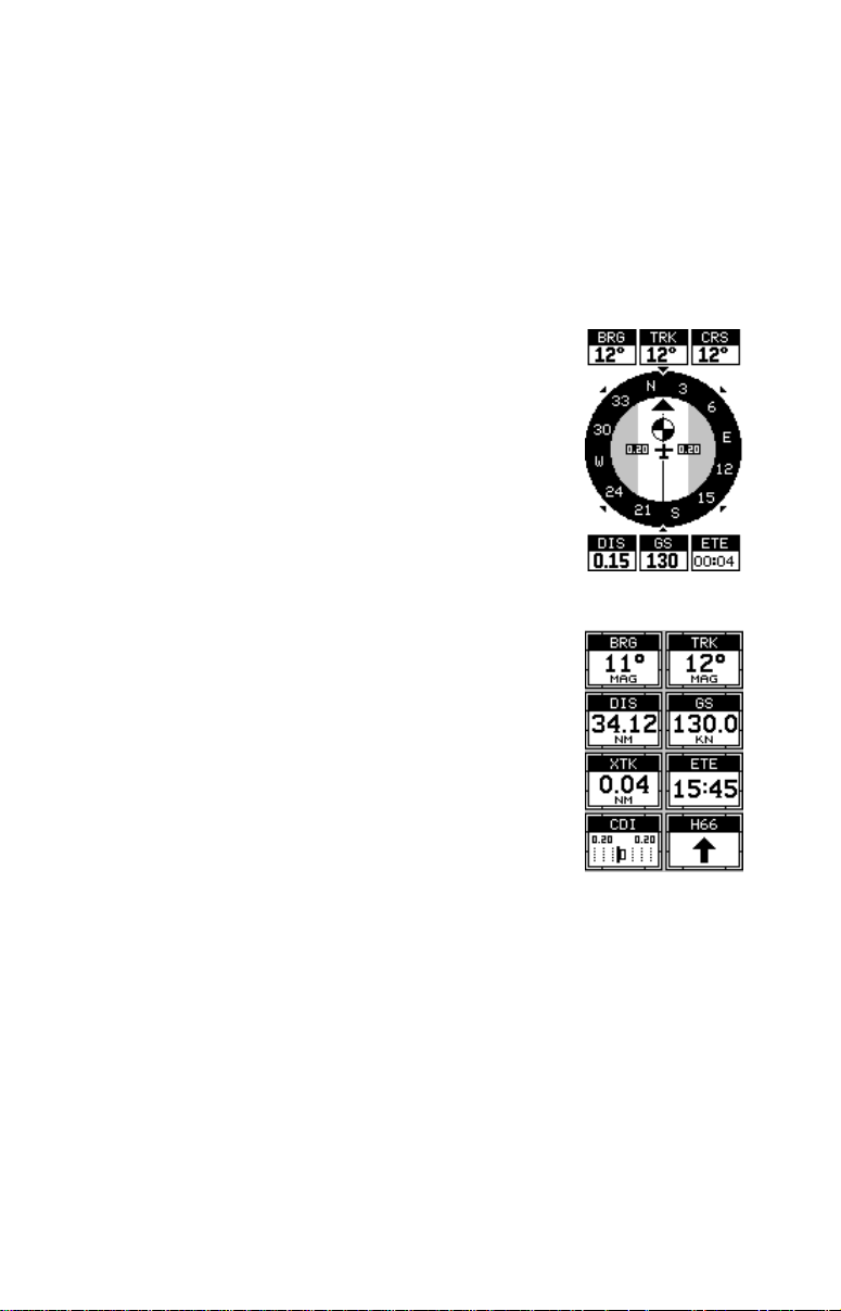
Nav Screen #1
This screen has a compass rose that shows not only
your direction of travel, but also the direction to a recalled waypoint. The navigation screen looks like the
one at right when you’re
not
navigating to a wa ypoint.
Your position is shown by the airplane in the center of
the screen. Your trail history, or path you’ve taken is
depicted by the line extending from the arro w. The arrow pointing down at the top of the compass rose indicates the current track (direction of tra vel) you are taking. This is also shown in the “TRK” (track) box in the
upper right corner of the screen. On the example shown at right, the tr ack
is 24°. The current ground speed (GS) shows in the box in the lower
center of this screen.
When navigating to a waypoint, Nav screen number
one looks like the one at right. Bearing to the destination waypoint is in the bo x in the upper left corner. Bearing is also shown by the large arrow pointing up towards the compass, abov e the present position arrow .
Distance from the present position to the waypoint (DIS)
shows beneath the compass on the lower left side of
the screen.
10
Page 17
Lines on either side of the present position show the current cross track
error range. Cross track error is the distance you are off-course to the
side of the desired course line. The course line is an imaginary line draw n
from your position when you started navigating to the destination waypoint. It’s sho wn on the screen as a vertical dotted line. The default f or the
cross track error range is 0.25 mile. For example, if the present position
symbol touches the right cross track error line, then you are .25 mile to
the right of the desired course. You need to steer left to return to the
desired course. The cross track error is also shown in the “XTK” box. In
the upper right corner is the course (CRS) box showing the direction from your starting position to the waypoint. Remember, a course is a proposed path from
the starting position to the destination. Track is your
actual direction of trav el.
A circle depicting your destination appears on the
screen as you approach the waypoint as sho wn on the
screen at right.
Nav Screen #2
This navigation screen shows all navigation information in large digital numbers. To view this screen, press
the PAGES key, then press an arrow key until the
“NA V1” label is highlighted. While it’s highlighted, press
the right arrow key . The screen shown at right appears.
Press the EXIT key to erase the menu.
This screen is composed of eight digital boxes. Track
(TRK) and ground speed (GS) data are all that show if
you’ re not na vigating to a wa ypoint. If y ou are navigating to a waypoint, then bearing (BRG), distance to
waypoint (DIS), estimated time en route (ETE), cross track error (XTK),
destination arrow , and the CDI also operate. See below f or more information on the CDI.
The destination arrow shows the direction to the destination when the top
of the screen is pointing in your direction of trav el.
Course Deviation Indicator (CDI)
Once navigation to a destination is established, the CDI shows y our distance to the left or right of the desired course. The vertical line in the box
shows both the direction you must steer to get back on course and the
distance to the course line. For example, if you’re travelling straight to-
11
Page 18
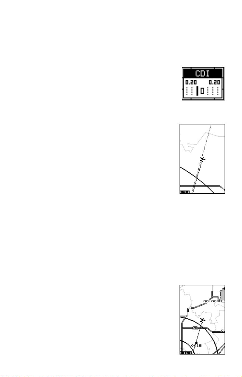
wards the destination, from the start, then the line stays in the center. If
you drift off course to the right, the line moves to the
left
. This signifies that
you need to steer to the left to get back on course. This is called “chasing
the needle”. If you steer to wards the line (needle), y ou’ll alwa ys be heading in the correct direction to get back on course.
The CDI’s range shows beneath the CDI label. On the
screen at right, the CDI range is .20 mile, which is the
default. You can adjust the range by selecting the
“ALARMS/CDI” label on the main menu. This is also
shown by the dotted lines at the far left and right side of
the CDI. If the solid line is on either of the dotted lines ,
then you are 0.20 mile off course. Remember, if the
line moves to the left, then you are too f ar to the
right
of
the desired course line and vice-versa.
Using the CDI with a mapping screen helps you visu-
alize your position in relation to the course. The map
screen on the right shows that we are off course to the
right. The vertical bar on the CDI shown above has
moved to the left side, sho wing the direction to the desired course line. The CDI gives you a quick, easy to
read visual indicator of your relationship between your
direction of travel and the desired direction.
Map
The AirMap 100 has a ground map of the world built inside. This map has
the majority of its detail in far southern Canada, the continental United
States and Hawaiian islands, northern Mexico, the Bahamas, and Bermuda. The map screens show your course and track from a “birds-eye”
view . If you’ re navigating to a wa ypoint, the map shows your starting location, present position, course line, and destination. You don’t hav e to navigate to a waypoint, however, to use the map.
A complete aviation database is included using Jeppesen® data . Airports, NDBs, V ORs, and other airspace
information (including obstructions such as radio and
TV towers) are ov erlaid onto the ground map .
Using the map is as simple as pressing the PAGES
key, then highlighting “MAP 1”. A screen similar to the
one at right appears. The airplane symbol in the center
of the screen is your present position. It points in the
direction you’ re travelling. The solid line extending from
12
Page 19

the airplane symbol is your plot trail, or path you’ve taken. The map’s
range shows in the lower left corner of the screen. In this example, the
map’s range is ten miles from the left edge of the screen to the right.
MAP-1
MAP-2 MAP-3
There are three different mapping screens. T o vie w the other map screens,
press the PAGES key, highlight the MAP label, and press the right arrow
key until the desired map screen appears. Press the EXIT key to erase
the menu. Map-2 (shown below) has navigation data added at the bottom
of the screen, beneath the map. The data includes bearing to waypoint
(BRG), track (TRK), and distance to wa ypoint (DIS).
Map-3 is similar to Map-2. It shows ground speed (GS), tr ack (TRK), and
the CDI at the bottom of the screen.
As you travel, the map slides past your present position, which always
remains at the center of the screen. The line e xtending from your position
shows the path you’ve tak en.
The Z-IN and Z-OUT keys zoom-in and out all maps to enlarge or reduce
their coverage area. The availab le ranges are: 0.1, 0.15, 0.2, 0.3, 0.4, 0.6,
0.8, 1, 1.5, 2, 3, 4, 5, 6, 8, 10, 15, 20, 30, 40, 60, 80, 100, 150, 200, 300,
400, 600, 800, 1000, 1500, and 2000 miles.
Jeppesen™ data shows at all zoom ranges, however, Lowrance has a
unique method of displaying this data. If you were to turn on all airports,
VORs , NDBs, and controlled airspaces at the same time without filtering
the data, the map screen would become so cluttered that it would be
useless. The AirMap 100 turns off virtually all aviation data at large ranges,
selectively turning on more data as you zoom in closer to your present
position or cursor location. The background land data also shows more
as you zoom in.
13
Page 20
Cursor
Pressing an arrow key turns on two dotted lines that intersect at the present
position symbol. These lines are called a “cursor” and hav e many uses. T o
turn the cursor on, simply press the arrow key in the direction you want
the cursor to move. This lets you view areas on the map that are away
from your present position. The zoom-in and zoom-out keys work from
the cursor’s position when it’s active - not the present position. You can
zoom in on any detail, anywhere. You can also place icons and w aypoints.
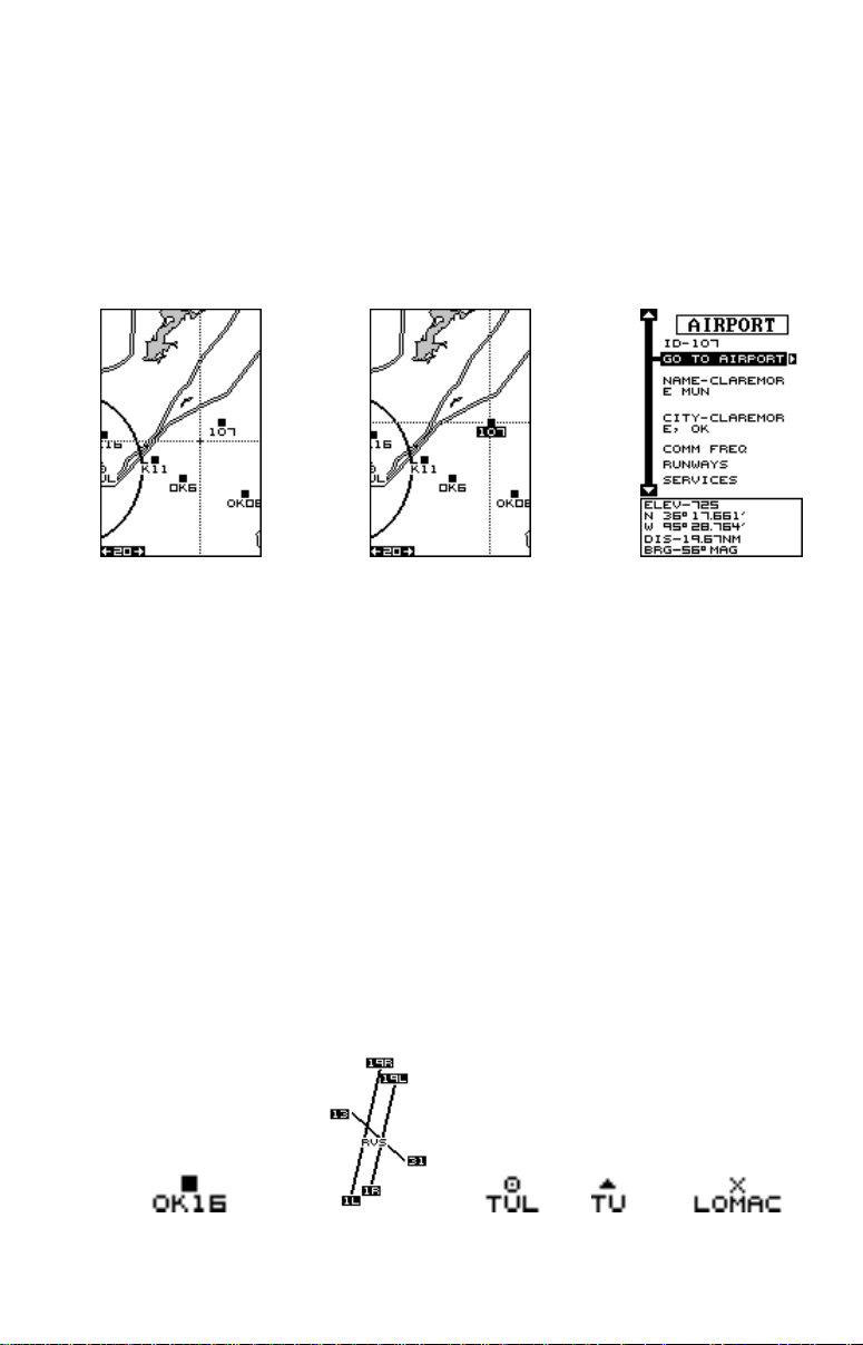
The cursor has an extremely useful f eature that lets you identify airports,
VOR’ s, NDB’ s, intersections, and user-defined wa ypoints. In this e xample,
an airpor t is identified. First, move the cursor to the airport. When the
label on the airport is highlighted, press the WPT key . The w aypoint screen
appears with the highlighted airport’s data showing. You can navigate to
this airport by pressing the right arrow key , view other inf ormation by highlighting the “COMM FREQ”, “RUNWAYS”, or “SERVICES” labels. Press
the EXIT key to erase this screen. You can select another feature in the
same manner or press the EXIT key to erase the cursor . The unit centers
your present position on the screen after erasing the cursor.
MAP SYMBOLS
Airports, VORs, NDBs, and Intersections
All airpor ts are shown as a square with its identifier beneath it. Larger
airpor ts are shown the same way until you zoom in closer, then their
runways become visible. Zoom in farther, and the runway numbers also
appear. VOR’ s are shown as a circle with a dot inside, while NDB’ s hav e a
triangle. Intersections are depicted as an “X”.
AIRPORT WITH
SMALL RUNWAY(S)
AIRPORT WITH
LARGE RUNWAY(S)
VOR NDB INTERSECTION
14
Page 21
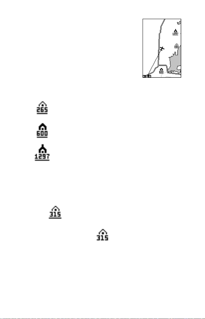
Obstructions
Your Airmap has obstruction capability. The database
installed in your unit lets you see ground obstructions
on the map display such as radio and television towers. The obstruction portion of the database covers all
of the continental United States, Alaska, and parts of
Canada, Mexico , and Bahamas.
On the screen shown at right, three obstructions are
shown. Three diff erent symbols are used to show them,
depending on their height. They are:
SMALL - 205 to 499 feet
MEDIUM - 500 to 999 feet
LARGE - 1000 feet and abov e
The elevation shows beneath the symbol. If a line is beneath the elevation, then the height is AGL, or above ground level. If no line shows beneath the height, then it is MSL or above mean sea le v el.
For e xample, this obstruction is
315 feet AGL:
This obstructions is 315 feet MSL:
Typically, you'll need to zoom in to a range of 40 miles or less to see the
large obstruction symbols, and smaller ranges to see the larger
obstruction's height and smaller obstructions. T o vie w smaller obstruction's
height, you may need to z oom in to the 5 mile range.
Obstructions are off by default. To tur n them on, press the MENU key,
while a map is showing, then select the “MAP-1 SETUP” label and press
the right arrow key. Now select “AIR MAP OPTIONS” and press the right
15
Page 22
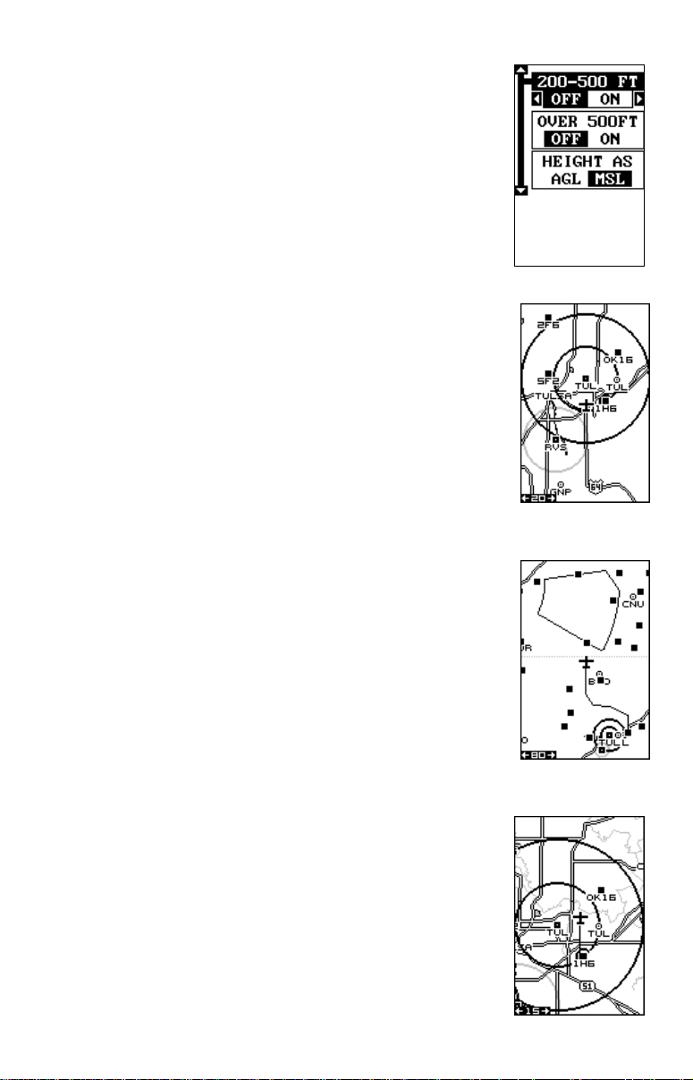
arrow key. Finally, select “OBSTR UCT OPTIONS” and
press the right arrow key. The screen at right appears.
The defaults are: obstr uctions from 205 to 499 feet
(shown as 200-500 on the menu) off. Obstructions 500
feet and above off. MSL defaults on. You can change
any of these by highlighting the desired menu, then
pressing the left or right arrow keys.
Airspace
This unit can show the following airspaces: Class B and
C airspace, control zones, control areas (CTA), Terminal Control Areas (TMA), prohibited, restricted, MOA’ s
(including training, danger, and caution areas), and alert
areas.
In this example, the Class C airspace surrounding Tulsa
International airport (TUL) is clearly visible as two dark
circles. The control zone airspace around Richard Jones
(Riverside) airport (RVS) is shown in gra y.
This screen shows the Eureka MOA east of Wichita,
Kansas on the 80 nautical mile range.
All airspace defaults are on for this unit e xcept warning
and alerts. An airspace alarm can be set that will warn
you if any of the above airspaces are within a preset
radius of your position. Another airspace alarm will “lookahead” and show how soon you will cross into an airspace. See the alarms section for more inf ormation.
Airspace Status
You can view information about the airspace you’re in
using the airspace status feature. To do this, press the
MENU key , then highlight “AIRSP A CE ST ATUS” sho wn
at the top of the next page.
16
Page 23
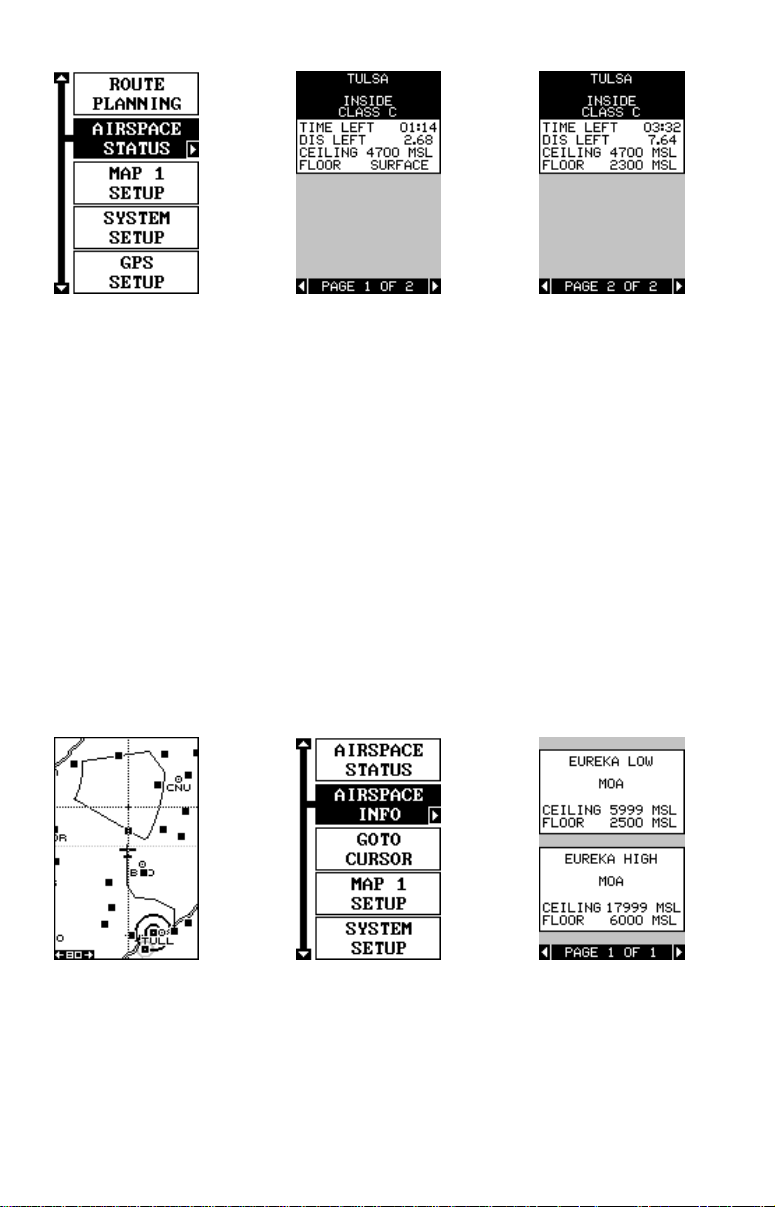
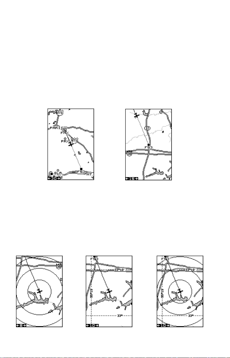
With “AIRSPACE ST ATUS” highlighted, press the right arrow k ey . The center
screen above shows ne xt. In this e xample, we’ re in Tulsa class “C” airspace.
The time and distance remaining until we leave the inner ring of the airspace
(assuming we keep the present track and speed) shows on this screen
above the ceiling and floor of the airspace. Since we’re near the center of
the class “C” airspace, (see the map at the bottom of the previous page)
page one shows information about the inner ring, page two shows outer
ring information. To view page two, simply press a right or left arrow k ey.
Press the EXIT key to erase the status screens .
Airspace Information
You can identify an airspace without physically entering it by using the
cursor. To do this, press any arrow key while a map is showing. In this
example, we’ re using Map 1. The cursor appears. Now move the cursor to
the desired airspace as shown below left. (Note: You may have to z oom-in
and/or zoom-out to view the airspace.)
With the cursor moved to the airspace, press the MENU key. A screen
similar to the one in the center appears.
Now highlight the “AIRSPACE INFO” label and press the right arrow key.
A message screen appears as shown above right.
17
Page 24
This is the information for the airspace that the cursor is resting on. If
there are more pages of information about the airspace, press the left or
right arrow keys to view them. To erase this screen, simply press the EXIT
key. To see information about another airspace, simply move the cursor to
that airspace and repeat these steps.
MAP SETUP
The map has many customization options. To change
them, first press the MENU key while a map is showing
on the screen. The “MAP SETUP” screen is highlighted.
Press the right arrow key. A screen similar to the one
at right appears.
Change Maps
Changes made to the map using the options in the
Map Setup is normally limited to only to the current
map screen. The change can be all map screens, however, by switching
the “THIS MAP” to “ALL MAPS” in the “CHANGE” menu. To do this, simply
highlight the “CHANGE” label, then press the right arrow key. To switch
back, repeat the above .
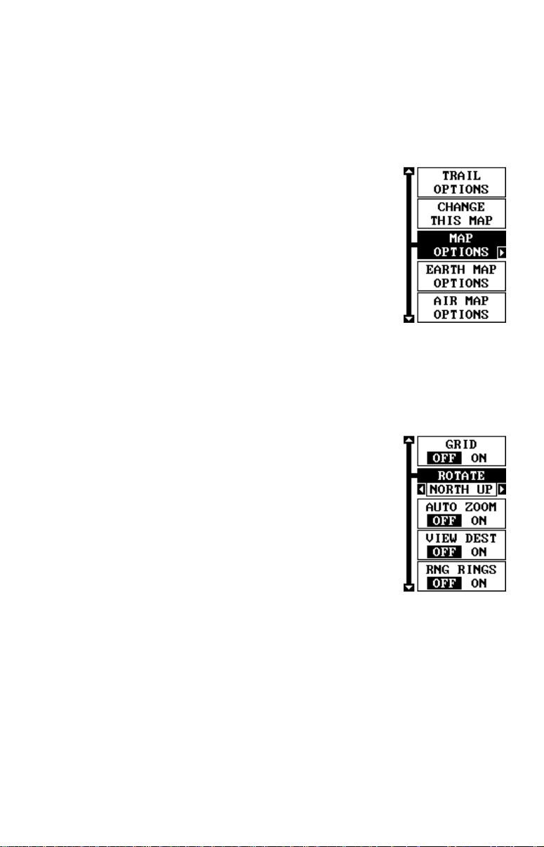
MAP OPTIONS
The following map options are listed under the “Map
Options” menu: Map Orientation, Auto Zoom, View
Destination, Range Rings, and Grids.
Map Orientation
By default, this receiver shows the map with north always at the top of the screen. This is the way most
maps and charts are printed on paper. This is fine if
you’ re always tra velling due north. What you see to your
left corresponds to the left side of the map, to your
right is shown on the right side of the map, and so on. However, if you
travel any other direction, the map doesn’t line up with your view of the
world.
To correct this problem, a track-up mode rotates the map as you turn.
Thus, what you see on the left side of the screen should alw ays be to your
left, and so on. A course-up mode keeps the map at the same orientation
as the initial bearing to the waypoint.
18
Page 25
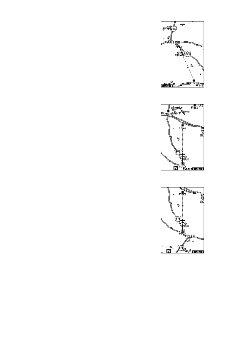
In the north-up view shown at right, we're travelling
southeast towards camp, saved as waypoint number
14. In this view, the present position indicator appears
to move to wards the lo wer right corner of the screen.
NORTH-UP
In the track-up view , the present position mov es straight
towards the top of the displa y . A "N" shows to help you
see which direction is north when the track-up mode is
on. Remember, in the track-up mode, the screen rotates as you change direction. It always keeps your
direction of travel (track) heading towards the top of
the screen.
TRACK-UP
In the course-up mode, the screen is locked into your
original bearing to the recalled waypoint, regardless of
your track.
COURSE-UP
To select the desired mode, first press the MENU key, select “MAP 1
SETUP”, then select “MAP OPTIONS”. Finally , select “R OTA TE” and press
the right or left arrow key until the desired mode appears. Press the EXIT
key to erase this men u.
19
Page 26
AUTOZOOM
This receiver has an autozoom f eature that eliminates much of the button
pushing that competitive units force you to make. It works in conjunction
with the navigation features. First, recall a waypoint. (See the waypoint
section for more information on navigating to a w a ypoint.) Then, with the
autozoom mode on, the unit zooms out until the entire course shows,
from the present position to the destination waypoint (recalled wa ypoint).
As you trav el towards the destination, the unit automatically begins zooming in, one zoom range at a time, keeping the destination on the screen.
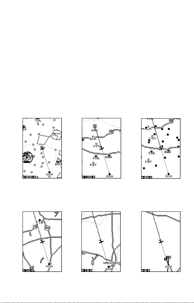
The screens below show a slice of the progression of a trip to Mangham
Regional airport in Nacogdoches, Texas. Screen number one is the start
and is on the 200 mile range. Intermediate stages progressiv ely zoom in
as it gets closer to the destination.
12 3
456
20
Page 27
To use the autozoom feature, first press the MENU key, select “Map 1
Setup”, then “Map Options”. Highlight “Auto Zoom”, then press the right
arrow ke y to turn it on. Press the EXIT key repeatedly to er ase the menus.
VIEW DESTINA TION
The GPS receiver normally centers the present position on the screen
and moves the map past it. If a waypoint is recalled, the unit can center
the waypoint on the screen, instead of the present position. To do this,
press the MENU key, select “Map 1 Setup”, then “Map Options”. Highlight
“View Dest”, then press the right arrow key to turn it on. Press the EXIT
key repeatedly to erase the men us.
VIEW DESTINATION
OFF
VIEW DESTINATION
ON
Range Rings/Grid Lines
The map screen can be customized with rings that are 1/4 of the range
and/or grids that divide the map into equal segments of latitude and longitude. To do this, press the MENU key, select “Map 1 Setup”, then “Map
Options”. Highlight the desired option, then press the right arrow key to
turn it on. Press the EXIT key repeatedly to erase the menus. A sample
screen of each type shows below.
RANGE RINGS GRID
21
BOTH RINGS & GRID
Page 28
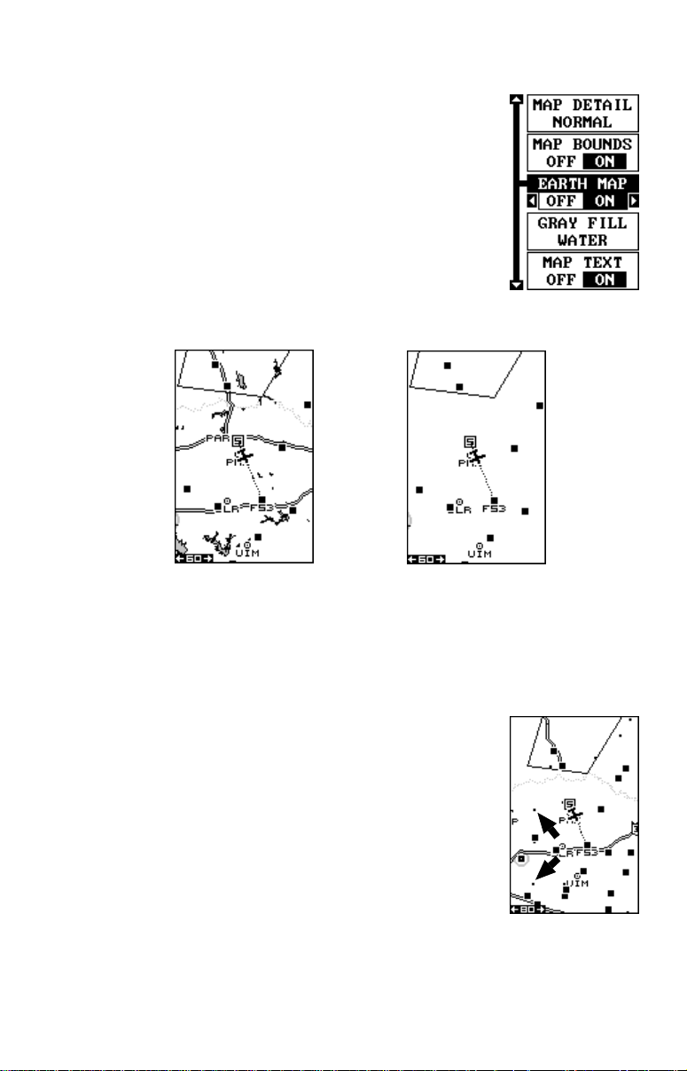
EARTH MAP OPTIONS
The earth map consists of the built-in background map
of the world. To change the Earth map options, first
press the MENU key, then select the Earth Map label.
Press the right arrow key. The screen shown at right
appears.
Earth Map On/Off
The background map can be turned on or off using the
“Earth Map” menu. The ear th map is the background
map that shows on the map screens. Simply highlight
the menu, then press the left arrow key to turn it off.
EARTH MAP ON
EARTH MAP OFF
T ext Labels
Select “Map Text” to turn all names on the map (such as Lake Tahoe or
Mississippi River) off or on. The def ault is “on”. Press the left arrow key to
turn them off.
Locations
Normally, text disappears as you zoom out. This
declutters the screen, making it easier to see significant map detail. T urning “Locations” on from the earth
map menu places a dot on the screen where a text
label should be when the screen is zoomed out. The
arrows on the screen at right show two locations where,
if zoomed in, text will show. (Note: this doesn’t affect
air data, just the earth map.)
Map Detail
The detail shown on the background map diminishes as the screen is
zoomed out. This prevents cluttering of the display, or overlapping of text
22
Page 29

and graphics which can make it unreadable. There are two detail levels:
normal and high. The difference between the two shows belo w. The screen
on the left is normal detail, on the right is high detail. Both screens are on
the 60 mile range. Normally , you’ll only see a diff erence in detail when the
unit is zoomed out to the 30 mile range or higher .
NORMAL DETAIL
HIGH DETAIL
To change the map’s detail setting, select “Map Detail” from the ear th
map menu, then press the right arrow key.
Gray Fill
When this unit is first turned on, all water (lakes, oceans, rivers) is filled
with gray to distinguish it from land, which is clear. (See below) To make
the land fill with gray and water remain clear, select the “Gray Fill” label
from the Earth Map menu, then press the left arrow key. Press the EXIT
key repeatedly to return to the mapping screen.
WATER FILLED
WITH GRAY
LAND FILLED WITH
GRAY
Normally, you'll want to fill water with gray when you're using the GPS
receiver ov er land and fill land with gr a y when y ou're using it o v er w ater.
23
Page 30

Map Boundaries
The Map Boundary feature shows the area that’ s covered by the detailed backg round map. The solid line on
the screen at right shows the coverage area of the detail in the built-in background map. If you download
SmartMap, WorldMap, or other more detailed maps,
the map boundary feature will show their cov erage areas, also . The default f or this feature is on. To turn it off,
select “MAP BOUNDS” from the “EAR TH MAP” men u
and press the left arrow key.
Symbols, Locations, and Contour s
These features on the Earth Map menu are used when special map data
is downloaded to this unit. You can turn each of the above on or off independently. The y only work with the special data. See the MapSelect section for more information on downloading map data to this unit.
AIR MAP OPTIONS
You can select the aviation symbols and airspaces that
you want displa yed on the screen. To do this, first press
the MENU key, then select “MAP-1 SETUP”. F rom this
menu, select “AIR MAP OPTIONS”. A screen similar
to the one at right appears.
You can turn all air data off by selecting “AIRMAP”,
then pressing the left arrow key. Use the up and do wn
arrow keys to select the desired symbol, then press
the right arrow key to turn it on or the left arrow ke y to
turn it off. T o turn the identifying text off on all airports,
VOR’s, NDB’s, and intersections, select “ID’S” and press the left arrow
key. You can also turn off all air ports, VOR’s, NDB’s, and intersections
from the air map options menu.
T o change the airspace selections, select “AIRSP A CES
SHOWN”. The screen shown at right appears.
Again, use the up and down arrow keys to move the
box to the desired airspace that you wish to change,
then press the right arrow key to turn it on or the left
arrow key to turn it off.
24
Page 31

Runway Extensions
This unit can draw a line on the screen that extends
the runway which makes it easier to line up on the
runway during final approach. To use the extension,
you must first navigate to an airport. (See the Navigation
section for more details.) In this example, (shown at
right) we’re navigating to Mangham Regional airport in
Nacogdoches, Texas. Next, select “Runways/
Extensions” from the “AIRMAP OPTIONS” menu shown
on the previous page. The screen shown below
appears.
Now select “RUNW A Y EXTENSION” on this menu. The
screen below left appears.
Use the left or right arrow keys to select the desired
runway. In this example, w e’ re using runway 36. When
the extension appears on the desired runway, press
the EXIT key to return to the map .
A line on the screen extends from the airport in line with the selected
runway.
To turn the extension off, repeat the above steps, but select “NONE” on
the above menu.
25
Page 32

TRAIL OPTIONS
The line extending from the present position symbol is
called a plot trail. You can customize the plot trail and
save trails using the trail options menu. To use it, press
the MENU key, select “MAP SETUP”, then “TRAIL
OPTIONS”. The screen at right appears.
Clear Trail
To erase the current plot trail from the screen, select
Clear Trail from the T rail Options menu. A message appears, asking if you really want to erase the plot trail.
Follow the instructions on the screen. When the trail is erased, the unit
returns to the map screen.
Flash T rail
By default, the plot trail flashes once per second. This typically makes it
easier to see the plot trail against the background map . To turn the flashing off, select “FLASH TRL” from the trail options menu. Press the left
arrow key to turn it off.
Update Options
By default, the plotter places a dot on the screen e very
3 seconds to create the plot trail. You can change this
time from once per second to once every thirty minutes. The plot trail can also be updated by distance
instead of by time. The distance update rate can be set
from 0.01 to once every 10 miles.
From the trail options menu, choose “UPDATE BY” to
change the update rate or type. To change the rate or
distance, simply select either the “UPDATE RATE” or
‘UPDATE DIS” menus as appropriate, use the left or right arrow keys to
adjust it, then press the EXIT key to erase the menu.
PLOT TRAILS - Save T rail
This unit automatically saves the current plot trail in
memory when you turn it off. You can save two other
trails in memory . To save y our current plot trail in a specific memory location, choose “SAVE TRAIL” from the
“TRAIL OPTIONS” menu. The screen shown at right
appears. Highlight the desired number that you wish to
save the current trail under, (i.e. “Trail 1 or Trail 2) and
press the right arrow key. Your current trail is saved.
Press the EXIT key to erase this men u.
26
Page 33

PLOT TRAILS - T rails Shown
The current plot trail shows on the plotter by def ault. To
place a previously sav ed trail onto the plotter, choose
“TRAILS SHOWN” from the Trail Options menu. The
screen shown at right appears. Highlight the desired
trail on this screen, then press the right arrow key to
select it. Press the EXIT key to erase this menu. The
selected plot trail shows on the plotter .
ICONS
The plotter has 28 symbols or “icons” available that can be placed anywhere on the screen. They can be used to mark airports that aren’t in the
database, ramps, or virtually any point of interest. An icon can be placed
at your present position or at the cursor’ s location. Ho wev er, you can’t use
icons for navigation.
Place Icon - Present Position
T o place an icon at y our present position, simply press
the ENT key while the mapping screen is on. The screen
shown at right appears. Use the arrow keys to highlight the desired icon. Now press the ENT key again.
The mapping screen reappears with the icon showing
at the position you were at when the ENT key was
pressed.
MAP-1 SCREEN
PRESS ENT KEY
SELECT ICON
PRESS ENT KEY
27
ICON PLACED
AT POSITION.
Page 34

Place Icon - Cursor Position
To place an icon at the cursor’s position, first use the arrow ke ys to mov e
the cursor to the location that you wish to place the icon. Ne xt, press the
ENT key. Now select the icon using the arrow keys. While it’s selected,
press the ENT key. The map reappears with the icon placed at the cursor
crosshairs. Press the EXIT key to erase the cursor . On the screens shown
below , the house icon w as placed at the cursor’s location.
MOVE CURSOR
PRESS ENT KEY
SELECT ICON
PRESS ENT KEY
ICON PLACED AT
CURSOR POS.
Icon Options
Icons can be erased from the plotter individually, all of
a specific type, or all at once. They can also simply be
turned off without erasing them. To make changes to
the icons, press the MENU key, then select “MAP
SETUP”, and finally select “ICON OPTIONS”. The
screen shown at right appears.
The first menu (ICONS OFF/ON) simply turns all icon
symbols off or on. This doesn’t erase the icons, it simply “hides” the icons from the map. You can use this
feature to temporarily de-clutter the display.
The DEL ALL ICONS selection does erase all of the icons from memory ,
Use this only if you want to erase all icons that have been placed on all
map screens.
To erase only a certain type of icon, select the DEL ICON TYPE menu.
The icon menu appears. Highlight the icon style that you want to erase
from memory, then press the ENT k ey. The unit returns to the map screen
with only the selected icons erased.
28
Page 35

You can delete individual icons by selecting the DEL
FROM MAP menu from the Icon Options menu. Once
this menu is selected, the unit returns to the plotter
screen with the cursor activated as shown at right. Use
the arrow ke ys to mov e the cursor to the icon that y ou
want to erase. Once the crosshairs are on top of the
icon, press the ENT key . The icon is immediately er ased.
Press the EXIT key to erase the cursor.
Map Downloading
The AirMap 100 has a background map of the world permanently installed
inside. You can send an enhanced map from an optional IMS MapSelect
CD-ROM to the unit using a personal computer .
BACKGROUND MAP
ONLY
BACKGROUND MAP
WITH IMS MAP
Important!
Downloading enhanced maps will erase the Jeppesen database. Y ou
can’t have both an enhanced map and aviation data in the unit
simultaneously.
Currently, the IMS MapSelect CD has the following databases:
IMS SmartMap™ data covers the 48 contiguous states and are broken
down into 64 different mapping regions. Contained in this database are
the names and locations of over 140,000 cities; 30,000 national, state
and county parks; 120,000 inland bodies of water plus coastal w aters out
to 25 miles; as well as nearly all state and federal highways, interstates
and routes.
IMS W orldMap™ data covers 35 specific regions around the globe including Canada, Europe, Indonesia and Australia. Contained in this database are the names and locations of cities, towns, provinces and states ,
29
Page 36

plus major roadways including tw o- and four-lane highwa ys, inland waterways and coastal h ydrogr aph y.
Coastal Navaid data covers coastal regions of the 49 U.S. States (excluding Hawaii), the District of Columbia, the Great Lakes and many large
coastal rivers and other large inland lakes. Contained are approximately
60,000 marine navigation aids. Each na vigation aid is displayed as a small
symbol, with information useful to the navigator (including light type (flashing or continuous), light color , and other aid markings) below the symbol.
To use one of these, install the software from the CD-ROM onto your PC
compatible computer according to the instructions supplied with the CD.
Next, connect the cable supplied with this unit from a serial port on the
computer to the GPS receiver. Now turn the unit on and adjust the
communication port baud rate to its highest level (Press MENU - SYSTEM
SETUP - COM PORT SETUP). Set the parity to “none” and 8 data bits .
Start the GDM-16 program on the computer. Click on the “GPS” label,
then click on “Options”. Select the com port that the GPS cable is connected
to and click “OK”. Now clic k on the “GPS” label, then “Initialize”. This starts
the communication between the GPS unit and the computer. If the
communications fail, try switching the baud rate on the AirMap 100 to a
lower setting. Once the communications are established, click on the “Map
Select” tab. Choose a memory partition to download a map into, then
choose a map. If you have problems, click on “Help”. There is extensive
help available on the GDM-16 prog ram.
TRANSFERRING MAP DAT A
Using the GDM Software, you ma y transfer up to two maps of your choice
to your GPS Unit.
1. Click on the MapSelect Tab.
2. Select a map by clicking on the desired database button (IMS
SmartMap, IMS WorldMap, or Coastal Navaids). A map appears on
the screen . Click the desired area that you want to download to the
GPS unit.
3. Select a memory partition by clicking on Memory Partition 1 or 2.
(Note: An y data already present in a selected memory partition will be
overwritten. When tr ansferring map data larger than 1 megabyte, both
memory partitions are automatically selected.)
4. Click the Transfer Map Data Button.
A status bar appears on both the PC and the GPS unit’s screen. When
the bar disappears, the transfer is complete. You’ll be able to see the
difference when the unit is zoomed in to ranges of ten miles or less .
30
Page 37

WINDOWS
The windows feature provides ten diff erent data screens chosen f or their
broad range of navigation information and ease of use.
T o use the windows f eature, press the P A GES key, then
highlight the “GROUP A” label at the bottom of the
screen. Group A is visib le in the background when y ou
switch to the windows group. Press the left or right arrow key to s witch between all off the groups. When the
desired group appears, press the EXIT key to erase
the Pages menu. A summary of the groups follow s. Note
that many of the groups have navigation data that require navigation to a waypoint in order to show data.
See the waypoint section for information on waypoint
navigation. All of these groups can be rearranged. See
the reprogramming section for more inf ormation.
Group A
This screen has two maps, one abov e the other. Each map works separately from the other . For e xample, the top map has autoz oom turned on,
while the bottom map doesn’t. To zoom in or out on the bottom map,
simply press the ZIN or ZOUT keys. The main menu also has selections
for the upper map and lower map setups.
GROUP A MAIN MENU
31
Page 38

Group B
This screen has a map in the track-up mode on the top
half with bearing (BRG), distance to go (DIS), track
(TRK) and the CDI on the lower half . (See page 10 for
an explanation of the CDI.)
Group C
A half screen map in the track-up mode again appears
at the top. The CDI shows in the middle of the screen.
Your present course (CRS) shows at the top of the CDI.
Track (TRK) and distance to go (DIS) show at the bottom of the screen.
Group D
This screen is the same as group C except ground
speed (GS) replaces distance to go (DIS) in the
lower right corner.
Group E
A CDI combined with a digital boxes makes up this
screen. Beneath the CDI are bearing (BRG), distance
to go (DIS), track (TRK), ground speed (GS), and altitude (ALT).
32
Page 39

Group F
This screen shows two position windows. Each can
show the position in different formats. (See Position
Format in the GPS Setup section for more details.)
Group G
The group G screen shows DGPS information. There
must be a DGPS receiver connected to the unit in order to use this screen.
The DGPS corrections at the top of the screen shows
a list of the satellites in view. The satellite’s number is
followed b y an identifier showing its status. They are as
follows:
OK DGPS corrections are in use by GPS receiver
and corrections are availab le.
OLD Unit hasn’t received corrections in last 60
seconds.
NA No correction available .
The DGPS station’s ID number , frequency, bit rate, signal strength, signal
to noise ratio (SNR), and time since the GPS receiver received the satellite corrections (AGE) all show at the bottom of this screen.
Group H
This is a time screen. An analog clock shows at the
top, f ollowed by a digital cloc k showing your local time .
The clock’s alarm setting shows in this window, also.
UTC time shows at the bottom of this screen. (UTC is
the time at the prime meridian. It used to be called GMT .)
To set the clock alarm, first press the MENU key, then
select “CLOCK ALM SETUP” and press the right ar-
33
Page 40

row key. The screen shown belo w left appears. Now press the right arrow
key. The screen below center appears. Using the arrow keys, enter the
alarm’s time. Press the ENT ke y . The unit returns to the clock alarm menu.
CLOCK ALARM
MENU
CLOCK ALARM
ADJUST MENU
CLOCK ALARM
SET
Highlight the “CLOCK ALM OFF ON” menu and press the right arrow key
to turn it on. Press the EXIT key to erase the menus. The unit returns to
the group with the alarm’s time showing in the cloc k’s window.
Group I
This group has estimated time enroute (ETE) at the
top of the screen, a trip timer, estimated time of arrival
(ETA), and the digital clock.
The trip timer measures the total time you have been
travelling. It starts counting when you exceed a preset
speed. The default is 5 miles per hour. You can adjust
this time from zero to 200 m.p.h.. To do this, press the
MENU key, then select “TRIP TIMER SETUP” menu.
The screen at right appears. Highlight the “START GS”
label, then press the left or right arrow keys until the
desired speed appears. Press the EXIT key to erase
this screen.
TRIP TIMER MENU
34
Page 41

Group J
There are three timers on this screen and an odometer
(TRIP METER). The trip timer is described in group I.
The trip meter measures the distance you’ve trav elled
since it was last reset. To reset the trip meter , press the
MENU key, then select “TRIP METER RESET” and
press the right arrow key. The unit retur ns to Group J
with the trip meter reset to zero.
The up timer starts at zero and counts up. The up timer
also has an alarm. The down timer starts from a user setting and counts
down to zero.
MAIN MENU
UP TIMER MENU
UP TIMER SET
T o start a timer , first press the MENU key, then highlight the desired timer
setup menu. In this example, we’re using the count up timer, so the UP
TIMER SETUP was selected. Now press the right arrow key. A screen
similar to the one above center appears. To star t the timer, simply highlight the “UP TIMER” menu, then press the right arrow key. To reset the
timer to zero, select the “UP TIMER RESET” men u. The up timer has an
alarm that can be set to sound at a preset time. (For example, one hour
from now, three hours, etc.) To set the alarm, highlight the “UP TIMER
ALM SET” and press the right arrow key. The screen at the upper right
appears.
Using the arrow keys , highlight the first number in the time that y ou w ant
to set. (The time is in hours, min utes, and seconds) No w press the up or
down arrow k eys until the desired number sho ws. Contin ue until the time
shown in the display is correct, then press the ENT key. The unit returns
to the timer menu screen. To turn the alarm on, highlight the “UP ALARM”
label. Press the right arrow key. Press the EXIT key to erase the menu.
The time you set shows in the “UP TIMER” box . The timer continues
35
Page 42
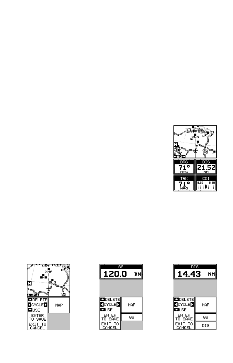
counting until you stop it. When it reaches the alarm’ s time setting, a tone
sounds. Press the EXIT k e y to shut the alarm off .
The countdown timer starts from a time that you enter and counts down
to zero. (Note: When the countdown timer reaches z ero, it begins counting up until you press the EXIT key. This tells y ou how long it’ s been since
the alarm sounded.) Use the “DOWN TIMER SETUP” menu to adjust the
countdown timer and reset it to zero.
Reprogram Window Groups
All of the windows groups can be customized. The changes you make to
the groups will remain in memory, even if all power is removed from the
unit. You can, however, retur n the groups to the factory settings using
“Reset Groups” on the system setup menu.
To customize a group, first switch to the g roup that you
wish to change. For this e xample, group “B” is used as
shown at right. Ne xt, press the MENU k e y, then select
“REPROGRAM GROUP”. The screen shown at the
bottom left corner of this page appears.
The first window appears at the top of this screen. To
select a different window, press the right or left arrow
keys until the desired window appears . T o add it to the
group, simply press the down arrow key. Continue
adding windows to the group in this manner until the group is filled with
windows. As you add windows to the group, their relative position on the
screen is represented by box es in the lower right side of this screen. When
the screen is filled with windows, the unit automatically saves your
reprogrammed group and returns to the group, as sho wn at the top of the
next page.
36
Page 43

If you finish selecting windows before filling the group
with windows, press the ENT key. To leave the
reprogramming menu without saving the changes,
simply press the EXIT key. In this e xample, the finished
group “B” looks lik e the one at right.
Reprogram Boxes
The digital box es on MAP 2 and 3 and both NAV screens
can be reprogrammed, changing the informations
shown by the box es .
To customize a screen, first switch to the screen that
you want to customize . Map-2 (sho wn at right) is used
in this example. Ne xt, press the MENU key, then select
the “Reprogram Boxes” menu. The screen shown below left appears.
This is the MAP-2 edit screen. The “BRG” bo x near the left corner flashes,
which means it’s ready for change. If you don’t want to change this box,
simply press the left or right arrow key to mo ve to the box that y ou do want
to change. In this example, we will change the bearing (BRG) box to
ground speed (GS). To do this, simply press the up or down arrow key
while the box is flashing. The box changes each time the arrow key is
pressed. When the desired box appears, then you can change another
box or save your changes by pressing the ENT key. If you want to leave
this screen without saving the changes, simply press the EXIT k ey . In this
37
Page 44

example, we simply changed the BRG to GS , then pressed the ENT ke y.
The screen on the far right on the previous page is the final v ersion. Use
this same method to change the NA V screens .
RESET GROUPS
To restore all window groups and boxes on the navigation and plotter
screens to their factory settings, first press the MENU ke y, then highlight
the “SYSTEM SETUP” label and press the right arrow ke y. No w highlight
the “RESET GROUPS” label on this menu. Press the right arrow key. A
message appears, asking if you really want to do this. Press the right
arrow key f or yes, or the left arrow k ey to exit without resetting the g roups.
DATAB ASES
Thanks to the Jeppesen database and the GPS receiver’ s ability to sav e
locations in memory, (waypoints) you can navigate to virtually any location. The AirMap 100 can also store up to 750 user waypoints. You can
store your present position, the cursor’s location, or enter latitude/longitude positions as waypoint locations.
The Jeppesen database contains airport, VOR, NDB, and intersection
locations, plus pertinent airpor t data such as com frequencies, runway
information, and services (fuel availability, repairs, oxygen, etc.)
You can also create routes composed of any airport , VOR, NDB, intersection or your own wa ypoints in any combination.
Aviation Database
To use the database, first press the WPT key. The
screen shown at right appears. This is the User Waypoint screen. You’ll use this screen to store and recall
your own locations. Now press the up arrow key. This
moves the black box to the “USER WPT” label at the
top of the screen. Pressing the right arrow ke y repeatedly switches to each of the database screens in the
order shown at the top of the next page.
38
Page 45

USER AIRPORT VOR
NDB INT
To find a particular airport, VOR, NDB, or intersection, first switch to the
appropriate database. In this e xample , we’ll use the airport database.
Suppose we’re planning a trip to Fort Smith Regional
airport in Fort Smith, Arkansas. There are three ways
to find this airpor t in the AirMap’s database. You can
find it by searching through the airport identifiers (ID),
airport name, or city. In this example, we kno w the airport identifier is FSM, so we’ll highlight the “ID” label b y
pressing the down arrow key once . No w press the right
arrow key. The screen at the top of the next page appears next.
39
Page 46

Select the first letter in the identifier by pressing the up
or down arrow keys until the letter “F” appears in the
“ID” field. When it does, press the right arrow key once .
This moves the selector to the second number in the
identifier field. Again, press the up or do wn arrow ke ys
until the letter “S” appears.
Finally, press the right arrow key one more time, moving the selector to the last number in the “ID” field, then
press up or down arrow keys until the letter “M” appears. The screen should look like the one at right.
Y ou can find an airport by using the airport name (name)
or city fields the same as the ID field. Simply move the
black box to the desired label, then use the arro w ke ys
to select the name.
After you’ve f ound the airport, press the EXIT key . The
screen shown at right appears.
At the bottom of the screen is the airpor t’s elevation,
which in this case is 469 feet. Beneath this is the
airport’s position, and at the v ery bottom of this screen
in the distance and bearing from your present position
to the airport.
Communication Frequencies
To view the communication frequencies used at the
selected airport, press the down arrow key and move
the black bo x to the “COMM FREQ” label, as shown at
right. Now press the right arrow k ey . The screen shown
at the top of the next page appears.
40
Page 47

This is the communication frequencies screen. In this
example, all applicab le com frequencies for Fort Smith
Regional airport are shown. Also, this airport has more
frequencies that can be shown on one page. Press the
left or right arrow keys to view the rest of the radio
information. When you’ re finished with this screen, press
the EXIT key. The unit retur ns to the previous database screen.
Runways
To view the runway information, press the down arrow
key on the airport database screen shown at the bottom of the previous page until the black box is on the
“RUNWAYS” label, then press the r ight arrow key. A
screen similar to the one at right appears.
The active runways a vailable at the time of your database are shown in the center of the screen. Data for
each runway is shown at the top and bottom of the
screen. In the example screen shown abov e, runway 7
- 25 has a hard surface, is 8000 f eet long and 150 feet
wide. It also has lights which are activated on 118.30
mHz.
To view the data for the other runway, press either the
right or left arrow key. The screen shown at right appears. No w information for runway 1 - 19 is shown.
If the airport has more than two runways, simply k eep
pressing the right or left arrow keys until the desired
runway appears.
When you’ re finished with this screen, press the EXIT
key to return to the airport database screen.
Services
To view the services available at the airport, highlight
the “SERVICES” label on the AIRPORT main menu
shown at the bottom of the previous page, then press
the right arrow key. The screen at r ight shows. After
viewing the information, press the EXIT ke y.
41
Page 48

OTHER AVIATION DATABASES
The VOR, NDB, and intersection databases work the
same as the airport. Simply switch to the desired
database, highlight the ID, name, or city (where
applicable) and select the location you wish to view.
When you’re finished with these screens, press the
EXIT key to erase them.
USER DATABASE - W AYPOINTS
This GPS receiver gives you the ability to create your own database of
locations, called “waypoints’. You can save your present position, cursor
position, or enter a coordinate and save it as a waypoint. For example,
you may wish to store the location of your parked car as a waypoint before starting on a hike. When you w ant to return to the car, all you ha ve to
do is recall the waypoint and the unit will sho w distance and bearing from
your present position to the car . This unit stores up to 750 waypoints.
Waypoint Men u
With few e xceptions, in order to sa v e, modify, or recall
a waypoint, you’ll use the waypoint menu, shown at
right. The current wa ypoint number shows at the top of
the screen. Its name appears beneath the “GO TO
WPT” label. The waypoint’ s position, distance and bearing from your present position to the wa ypoint, and the
date and time the waypoint was saved show at the
bottom of the screen. It’ s icon sho ws just to the right of
the distance and bearing. In short, all of the detail about
the waypoint shows on this screen.
Saving Y our Present Position as a W a ypoint (Quic k Sa ve Method)
To save your present position, simply press the WPT
key twice. Your current position is placed into the first
availab le w aypoint number on the list. A message appears on the display telling you the w aypoint number it
just used. This also momentarily places you in the wa ypoint menu. Anytime this menu is showing, simply press
the WPT key once and the unit will store your present
position on the waypoint list. In this case, waypoint
number one was assigned when the WPT key was
pressed.
42
Page 49

Saving The Cursor Position as a Waypoint
When the cursor is showing on the map and you press the WPT key
twice, the cursor’ s position is placed into the first availab le waypoint number. In the example screen shown below, the cursor is placed at the
desired location. Pressing the WPT twice causes wa ypoint number two to
be placed at the cursor’s crosshairs. (Waypoint 2 was the next available
waypoint number.) A message appears on the display telling you the
waypoint number it just used. Wait a f ew seconds and the menu will clear
automatically. Press the EXIT key to erase the cursor.
MOVE CURSOR TO
DESIRED LOCATION
PRESS WPT KEY
TWICE
Saving Y our Present Position as a Wa ypoint
(Select Number Method)
The method shown previously doesn’t let you choose
the waypoint number. You can pic k the w a ypoint n umber, then sa ve your present or cursor position. To save
your present position, press the WPT key once. (If
you’ re saving the cursor position, first mov e the cursor
to the desired location, then press the WPT key.) A
screen similar to the one at right appears.
Highlight the “WPT” label near the top of the screen.
Press the right or left arrow keys until the desired wa ypoint number appears that you wish to save your
present (or cursor) location under. Wa ypoint number 4
is used in this example. Now select “CREATE WPT” . A
screen similar to the one at right appears. Finally, highlight “CURRENT POS” and press the right arrow key.
The unit returns to the waypoint screen with the position saved under the selected w aypoint n umber .
.
43
Page 50

Saving a New P osition
T o sa ve a position other than the cursor’s or the present
position as a waypoint, first select the waypoint number as described on the previous page. Next, select
“CREATE WPT”. The screen shown at the bottom of
the previous page appears. Select “ENTER POS”. The
screen shown at right appears. Using the arro w keys,
enter the latitude and longitude of the position that you
want to save. (Note: latitude and longitude is the default, howe ver if UTM or other position f ormat is in use,
this screen will let you enter the position in the format
that’s currently in use.)
Waypoint A veraging
Although electronic position finding devices such as this one show the
position in precise digital numbers, there is some ambiguity in the displayed position. With position pinning turned off, you can see this by w atching the position displayed on the unit mo ve while you’ re standing still. This
is due to many factors; SA, atmospheric conditions, the number of satellites being tracked and their location relativ e to y our position, and so on.
However, even with SA tur ned on, this GPS receiver can show surprisingly accurate position information. If you wish to increase the accuracy
of a saved position, use the waypoint averaging method. This method
requires the unit to remain untouched at the location that you want to
save, preferably for at least one hour. Longer times will result in a better
position. The unit averages all of the positions reported by its GPS receiver , resulting in typically higher position accuracy.
To use this feature, first press the WPT ke y and select
a waypoint number, then select “CREATE WPT”. The
screen at the bottom of the previous page appears.
Now select “AVERAGE POS”. The screen shown at
right appears. Your present position shows at the top
of the screen. A box with a plotter graphically shows
the movement of your average position. The number
of positions or points taken appears beneath the plotter. The position is updated once per second. No w place
the unit where it has an unobstructed view of the sky.
At the end of the position gathering time, press the ENT key to save the
averaged position.
44
Page 51

Project a Waypoint
You can save a waypoint even if you don’t know it’s
position or location on the map. This unit lets y ou project
the location of a waypoint from a known waypoint using only bearing and distance from the known waypoint. This is useful if you don’t kno w the latitude/longitude of a location, but you do know the distance and
bearing from a saved waypoint or your own position.
(Note: To project a waypoint from your present position, you must first save your present position as a
waypoint.)
To use this feature, press the WPT key, then select a
waypoint number that you want to save the projected
waypoint under. Waypoint 5 is used in this example.
Now select “CREA TE WPT”. Finally , select “PROJECT
POS”. The screen shown above appears.
The unit needs a location (reference waypoint) to
project the new waypoint from. The default reference
is waypoint number one. Highlight the “REFERENCE
WPT” label on the Project WPT menu and press the
right arrow key. The screen above right appears. Select a waypoint using either the waypoint number, or
waypoint list. When you’v e chosen the wa ypoint, highlight the “SET REFERENCE” label and press the right
arrow key. The unit returns to the Project WPT screen
shown at right. The starting waypoint you chose sho ws
in the middle of this screen. Now set the distance from
the starting waypoint to the projected waypoint b y highlighting the “SET DISTANCE” label and pressing the
right arrow key. Use the arrow k eys to set the distance,
then press the ENT key when you’ re finished. The unit
returns to the Project WPT screen. Now enter the bearing from the starting waypoint to the projected waypoint by selecting “SET BEARING” from the Project
WPT screen. Once y ou’ve entered the bearing, the unit
returns to the Project WPT screen with the distance
and bearing showing at the bottom of the screen, as
shown at right. In this example, a distance of 10.5 miles
and a bearing of 164° was used. Now press the ENT
key. The unit saves the projected location under the
waypoint number that y ou pic k ed at the beginning.
45
Page 52

SELECTING A USER WAYPOINT
In order to edit or navigate to a user waypoint, you
must first select it. There are three w a ys to do this: by
waypoint number , wa ypoint list, or search by name. All
selection methods are on the user waypoint menu.
Waypoint Number
To select a waypoint by its number, simply highlight
the “WPT” label at the top of the w a ypoint men u, then
press the left or right arrow keys until the desired wa ypoint number appears.
Waypoint List
The waypoint number selection method forces you to
scroll through all waypoint numbers , whether there’ s a
location saved in them or not. The waypoint list is composed only of saved waypoints. To use the list, select
“WPT LIST” from the wa ypoint menu. The screen shown
at right appears. The names of all waypoints stored in
memory show on this list. Simply highlight the desired
waypoint and press the right arrow k ey to select it. The
waypoint men u reappears.
(Note: When created, a waypoint is given a default name designated by
an asterisk (*). Default names are not shown on the map. The waypoint
number is shown until it’ s renamed.)
EDITING A WAYPOINT
You can customize a waypoint by giving it a name or change it’s position
or icon. To do this, first press the WPT ke y. The waypoint screen appears .
Follow the instructions below f or each item.
Edit Position
Any latitude/longitude can be assigned to any wa ypoint
by manually entering it using the keyboard. First select the waypoint number that you want to save a position under from the waypoint menu. Next, highlight
“EDIT POSITION” and press the right arrow key. The
screen shown at right appears. Using the left and right
arrow keys, highlight each n umber in the position and
change it using the up and down arrow keys. When
you’ re ready to save this position and return to the wa ypoint screen, press the ENT key. Note: You can also
use this method to change the position of an existing wa ypoint.
46
Page 53

Edit Name
You can assign a name to each waypoint. The name
can have up to eight characters . T o do this, first select
the waypoint that you wish to name , then choose “EDIT
NAME” from the waypoint menu. A screen similar to
the one at right appears.
Press the up or down arrow keys to select the first
letter in the name. Press the right arrow key to highlight the next position in the name. Repeat this sequence until you’ve entered all of the letters in the w aypoint name. Press the ENT key to accept this name, the WPT key to
erase all characters in the name, or the EXIT key to leave this screen
without saving any changes.
Edit Icon
To change the icon assigned to a waypoint, first select
the waypoint, then choose “EDIT SYMBOL ”. The screen
at right appears. Use the arro w k eys to select the icon
that you want to assign to the wa ypoint, then press the
ENT key. The waypoint now has the new icon.
NAVIGATION
The AirMap 100 makes it easy to navigate to any location. All y ou have to
do is select the location from the database, then highlight the “GO TO”
label on the waypoint screen and press the right arrow key. The unit immediately shows navigation inf ormation to the waypoint
on all navigation, map, and windo ws screens .
In this example, Hallib urton field in Duncan, Oklahoma
was recalled. It’s 142 nautical miles from our present
position on a bearing of 222°. To do this, we simply
pressed the WPT key, selected the AIRPORT database, then selected Haliburton field. Ne xt, the “GO T O
AIRPORT” label was selected and the right arrow key
pressed. The unit returned to the mapping screen that
was in use before we pressed the WPT ke y, (shown at
right) which happened to be MAP-2.
47
Page 54

Navigating to a cursor location
This unit lets you navigate to a location without storing it in the waypoint
database by using the map and cursor. To do this, first switch to a map.
Now move the cursor to the location that you want to navigate to. Next,
MOVE CURSOR TO
DESIRED LOCATION
PRESS MENU KEY,
THEN PRESS RIGHT
ARROW KEY
NAVIGATING TO
CURSOR
POSITION
press the MENU key. A ne w , highlighted menu appears on the list: “Go To
Cursor”. Press the right arrow key. It now shows navigation data to the
cursor location (shown as “D” on the map). See the screens below .
Navigating to a Waypoint using the Map
The unique “birds-eye” view used by the map gives
you an easy wa y to navigate to a wa ypoint. On the map
screen shown at right, the airplane is your present position. The box with the “S” in it was your starting location when the waypoint was recalled. The dotted line is
called a course line and is the shortest path from the
starting location to the destination. The “D” on the map
screen at the top of this page is the cursor destination,
when the cursor position is used as a destination.
(When an aviation database is used as the destination, it’s designator will sho w instead of the “D”. ) If you
follow the course line, you’ll reach the destination, covering the shortest
distance in the least time.
CAUTION!
The AirMap 100 does NOT tak e land features, altitudes, restricted or prohibited areas, or any other feature into account when it projects the trac k
line on the screen. Theref ore, y ou m ust use care when navigating on the
track line and av oid any object that may be in y our path to the destination.
48
Page 55

OTHER W A YPOINT OPTIONS
Move a Waypoint
You can move all information from one user waypoint
number to another to help organize the waypoints. In
this example, we’ll move all of the information in waypoint number 1 to waypoint n umber 10. To do this, highlight the “MOVE WPT” on the user waypoint screen
and press the right arrow key. The screen shown at
right appears. The “From” label is highlighted at the top
of the screen. Press the right arrow key until the wa ypoint number that you want to move appears. In this
example, we selected waypoint number 1. Now press
the down arrow key once to highlight the “To” label.
Press the left or right arrow key until the number that
you want to move the waypoint to appears. Again, in
this example, we chose to mo ve wa ypoint number 1 to
waypoint number 10, so we pressed the right arrow
key until “10” appeared. As y ou can see on the screen
above, wa ypoint number 1 is showing in the “From” box.
Now press the ENT key. The “From” box is now empty
and the “To” box has w a ypoint n umber 10.
Note: The names in the “From” and “To” box es are not the wa ypoint numbers - they are the waypoint names .
Press the EXIT key to erase this men u.
Delete a Waypoint
To erase all of the information in a user waypoint, first press the WPT k ey,
then select the waypoint you want to erase. Now highlight the “DELETE
WPT” label and press the right arrow key. A message appears, asking if
you really want to delete this wa ypoint. Press the right arro w key to delete
it, the left to exit without deleting the wa ypoint.
Delete All W a ypoints
You can remove all of the waypoints from the unit’s memory. To do this,
press the MENU key, then highlight the “SYSTEM SETUP” menu and
press the right arrow key. Now highlight the DEL ALL WPTS label. The
unit removes all wa ypoints from memory . Note: This also removes all routes
from memory .
49
Page 56

“NEAREST” FEATURE
The AirMap 300 can show a list of the nearest airports,
VORs , NDBs, intersections, or user w a ypoints to y our
present position.
To use this feature, simply press the Z-OUT and Z-IN
keys
at the same time
. The screen shown at right appears. The nearest airports show first. The airpor t’s
range and bearing that’s closest to y our present position shows at the top of this list. The other airports are
shown on the list in increasing order from your present
position. To view airports not shown, press the down arrow key to the
bottom of the list and hold it. The list scrolls upward until the last airport
appears.
To view information about any of these airports, highlight the desired airport, then press the right arrow key.
For the screen shown at right, we highlighted the “1H6”
airport, then pressed the right arrow key. You’ll recognize this as the airport database screen. You can view
any information about this airport using the arrow and
EXIT keys. If you wish to navigate to this airport, simply highlight the “GO TO AIRPORT” label, then press
the right arrow key. Press the EXIT k ey to return to the
nearest waypoint list.
To see the other lists, move the black box to the “AIRPORT” label at the
top of the screen, then press the left or right arrow keys . This rotates the
“nearest” f eature to the other lists . All of these work identically to the airports list. You can view all data or navigate to any item on any list.
Press the EXIT to return to the navigation, mapping, or windows screen.
50
Page 57

Waypoint Options
You can customize the method used to show a user
waypoint on the map screens . To do this, first press the
MENU key, then select “MAP SETUP”, finally select
“WAYPOINT OPTIONS”. The screen shown at right appears. You can turn all of the wa ypoints, their symbols,
names, or numbers on or off. Simply select the desired
label, then press the appropriate arrow key. Press the
EXIT key to erase this men u.
ROUTES
You can connect several waypoints (user or aviation) together to form a
route. When y ou recall the route, the unit shows navigation inf ormation to
the first waypoint in the route, then when you reach that waypoint, it
switches to the next w aypoint, and so on until you reach the last w aypoint
in the route.
Create a Route
To create a route, first press the MENU key, highlight
the “ROUTE PLANNING” label, and press the r ight
arrow key. The screen shown at right appears.
This unit can store up to 99 routes. Route number one
shows on this page. If y ou wish to create a route using
a different number, simply press the left or right arrow
keys until the desired route number appears. In this
example, how e v er, we’ll use route number one.
If you wish to name the route, highlight the “EDIT NAME”
label and press the right arrow key. Use the arrow k eys to name the route,
(you can use up to eight characters in the name) then press the ENT ke y
when you’ re finished.
The gray boxes in the lower half of the screen comprise the list of waypoints that form the route. To add
waypoints to the route , highlight the first gray bo x in the
middle of the screen and press the right arrow key. The
screen shown at right appears. To add a waypoint to
the route from the waypoint tab le, select the “ADD WPT”
label. The screen shown at the left on the next page
appears.
51
Page 58

Add From Waypoint List
This screen is virtually identical to the database screen Select a user
waypoint, airport, V OR, NDB , or intersection. You can select a user wa ypoint either by using the waypoint number, waypoint name, or from the
waypoint list. After selecting the wa ypoint, highlight the “ADD TO R OUTE”
label and press the right arrow key. The unit returns to the route screen
with the first waypoint at the top of the list. Highlight the next waypoint
location beneath the first waypoint and press the right arrow key. Now
repeat the previous steps to select the second waypoint for your route.
After selecting the second waypoint, the unit returns to the waypoint list
screen. The second waypoint shows beneath the first one, with bearing
and distance from the first waypoint in the route to the second showing
under the second waypoint’ s name .
SELECT FIRST
WAYPOINT AND ADD
TO ROUTE
UNIT RETURNS TO
ROUTE PAGE
REPEAT UNTIL
ALL WAYPOINTS
ARE IN ROUTE
Add From Map
You can add waypoints from the map, even create new ones . To do this,
select “ADD FROM MAP” from the menu as shown below left. A screen
similar to the one below center appears. Using the arrow keys, move the
cursor to the desired waypoint or location. No w press the ENT key to add
it to the route. If it’s an e xisting waypoint, it will be added to the route . If you
52
Page 59

mark a location with the cursor that isn’t a waypoint,
the unit will create a waypoint and add it to the route. To
add another location or waypoint to the route, move
the cursor to that location and press the ENT key. When
you’ re finished, press the EXIT key. The screen at right
appears.
The total route distance shows at the bottom of the
screen. Continue selecting waypoints until all of the wa ypoints in the route are on the list. Your route is now
saved in memory. Press the EXIT key to er ase the men us.
Delete a Waypoint
To remove a waypoint from a route, first select the route, then select the
waypoint that you want to delete and press the right arrow key. Highlight
the “Delete” label on this menu and press the right arrow key. The unit
returns to the route list with the waypoint removed from the list. (Note:
This doesn’t delete the waypoint from the database, it simply removes it
from the route.)
Waypoint Statistics
By default, this unit shows the distance and bearing from each waypoint
in the route to the next. It will also show estimated time en route (ETE),
estimated time of arrival (ETA), or the waypoint names (NAMES). T o view
the different statistics, highlight the “SHOW-DIS/BRG” label, then press
the left or right arrow key until the desired statistic appears.
Following a Route - Direct To Method
Before starting the route, you’ll need to decide if you want to start at the
first waypoint and travel forward to the last waypoint or start at the last
waypoint in the route and tra vel backw ards (rev erse) to the first waypoint.
The default is forward. You can also start at the closest waypoint to your
position, then travel f orward or rev erse through the route using the “A UT O
START” feature .
To follow a route, first select the route number that yo u
wish to follow by highlighting the “Route #” label, and
pressing the left or right arrow keys until the desired
route number appears. In this example we’ re using route
number one (shown at right). To run the route from the
last waypoint to the first, highlight the “R UN” label and
press the right arrow key to change it from forward to
reverse.
53
Page 60

Now highlight the first waypoint in the route that you
wish to start with and press the right arrow key. (The
first waypoint in the route is used in this e xample.) The
screen shown at right appears. Now select “DIRECT
TO” and press the right arrow key.
The unit returns to the last used navigation, mapping,
or windows screen. In this example, map screen 1 w as
in use. A box with the “S” inside represents your location when you started the route. A dotted line shows
from your starting position to the waypoint. A dashed
line extends from this waypoint to each of the other
waypoints in the route . F ollow these lines to get to each
of the waypoints. When you enter the radius set by the
arrival alarm, the unit automatically switches to the next
waypoint on the list, showing navigation data to that
waypoint, and so on until the last w aypoint on the route
list has been reached. (Note: The arrival alarm does
not have to be turned on.) The unit continues to sho w
navigation data to the last waypoint in the route until
you end the navigation. (See “Cancel Navigation)
Following a Route - Auto Start Method
You don’t have to choose the starting waypoint in a route . Selecting “AUT O
ST AR T” on the route planning menu, starts navigation along the
leg
of the
route that is closest to your present position. For e xample, imagine a route
with four wa ypoints, n umbered 1 thru 4. When the route was started, the
first leg of the route (from waypoint #1 to wa ypoint #2) w as the closest to
the present position. Theref ore, the unit shows navigation information to
waypoint number 2. The first leg of the route, from #1 to #2 is shown on
the screen by a dotted line. Once you arrive at waypoint number 2, the
unit switches to the ne xt waypoint in the route, and so on. The rest of the
route navigation is used normally .
Waypoint Inf ormation
To see details about the highlighted waypoint, select
the waypoint from the list of waypoints on the route
screen, then press the right arrow key. The screen at
right appears. No w select “WPT INFO”. The screen at
the top of the next page appears.
54
Page 61

The selected waypoint number appears at the top of
this screen. In this example, Jones airport (Riverside)
in Tulsa was selected. Information about the waypoint
shows at the bottom of the screen. When you’re finished with this screen, press the EXIT key to erase it.
Delete a Route
To erase a route, highlight the “ROUTE #” label on the
route planning menu, then select the route you want to
erase. Next, highlight the “DELETE ROUTE” label and
press the right arrow key. A message appears, asking
if you really want to erase the route. If you press the
right arrow key, the route will be erased. If you select
“Yes” (by pressing the right arrow key) the unit then
asks if you want to erase the waypoints used in the
route from memory also. Press the right arrow key again
to erase them, or the left arrow key to leave the waypoints in memory . The unit returns to the routes menu.
Press the EXIT key to erase the menu.
CANCEL NA VIGATION
This unit continues to navigate to a recalled wa ypoint,
the last waypoint in a route , or the cursor position until
you stop it.
To stop the navigation function, press the MENU key,
then press the up or down arrow ke ys until the “Cancel
Nav” label is highlighted. Press the right arrow k ey . The
unit stops showing navigation information.
Navigation Notes
If you are navigating with this unit, either to a waypoint or in a route and
shut it off, it will preserve the current wa ypoint number that it is navigating
to. It also sa ves the current route (if it is in use) and the route’s forward or
reverse order. When you turn the unit on, it will show navigation data to
the waypoint as soon as it locks onto the satellites as if it had ne v er been
turned off.
55
Page 62

SYSTEM SETUP
Many features are listed under the “System Setup” label on the main menu. These commands aff ect the basic operation of the unit. To use them, press the MENU
key, then “System Setup”. The screen at right appears.
Audio/Screen
To turn the speaker off or on, adjust the contrast and
backlight, select “AUDIO/SCREEN” from the System
Setup menu. The screen shown below appears.
Sound
T o turn the speaker off , highlight the “SOUND” label as
shown at right, then press the left arrow key. Note: This
turns the speaker completely off. The unit will not sound
a tone when a key is pressed, nor will any alarm sound.
The alarm messages will still flash on the screen, however.
Contrast
T o adjust the displa y’s contr ast, highlight the “Contrast”
label. Press the right or left arro w keys until the screen’ s
contrast is best for the lighting conditions.
Backlight
The display has lights that can be turned on for night use. To turn the
lights on, simply press the PWR key. To turn them off, press the PWR key
again. A light bulb indicator on the satellite status screen shows when the
lights are on.
The default light level is maximum. To reduce the level, select “BACKLIGHT”, then press the left arrow key until the lights are at the desired
lev el. To increase the light level, press the right arrow key.
The lights automatically turn off after 30 seconds to preserve the battery
power. It will do this even if the external power is applied to the unit. The
time delay is adjustable from 5 to 240 seconds b y selecting Light Dly from
the System Setup menu . You can also turn the lights on continuously
from this menu. Highlight this menu, then press the right arrow key to
increase the time the lights are on, the left arrow key to decrease it.
56
Page 63

Set Local Time
When this unit is first initialized, it may not show the
correct time for your location due to daylight savings
time, time zone variances , and so on. If the time shown
on the clock displays is incorrect, select “SET LOCAL
TIME” from the system setup menu and press the right
arrow key. The screen shown at right appears.
Use the left or right arrow keys to select the number in
the current time that you want to change. Use the up or
down arrow keys to change the number. Press the ENT key to save the
change, the EXIT key to erase the men u without changing it.
Units of Measure
You can view data in three different f ormats: statute, nautical, and metric.
The default is nautical. The chart below shows the settings for each.
Statute Nautical Metric
Distance ....... miles ...................nautical miles ...kilometers
Speed ........... miles per hour.....knots ................kilometers per hour
Altitude ......... feet .....................feet...................meters
The unit will also show bearing in degrees true or magnetic, and the clock in 12 hour (a.m./p.m.) or 24 hour
formats. To change a unit of measure, first select
“CHANGE UNITS” from the System Setup menu. Highlight the desired selection, then press the left or right
arrow key. You can change any or all of the settings on
this page. When you’re finished, press the EXIT key.
NMEA / DGPS
This product transmits data through the power/data port in the back of the
unit using NMEA 0183 format, version 1.5 or 2.0. The data is used by
other electronic devices such as marine autopilots for position and steering information.
DGPS on the other hand, is a data input. DGPS is an acronym f or Diff erential Global Positioning System. Currently, it relies on a system of groundbased transmitters that send correction signals to small DGPS receivers.
DGPS gives you more accurate positions than is otherwise possib le .
All wiring connections to this GPS receiver are made through the power
57
Page 64

cable. See the sample wiring diagrams on the next page for general wiring procedures. Read your other product’s owner’s manual for more wiring information.
Once the cables are wired, turn the unit on, press the menu key, and
select “NMEA / DGPS CONFIG” from the System Setup menu. A screen
similar to the one shown below appears.
NMEA Output
T o turn the NMEA output on, highlight the “NMEA OUT”
menu (shown at right), then press the right arrow key.
If your other equipment works, then no setup will need
to be performed. If your other equipment doesn’t recognize the NMEA data being sent by the AirMap 100
and the wiring is correct, then you may need to change
the NMEA or the serial communication settings.
Configure NMEA Output
Highlight the “Configure NMEA” menu, then press the
right arrow key. The screen shown below appears.
NMEA 0183 Version
There are two versions of the NMEA data, 1.5 and 2.0.
If your other equipment requires 1.5, press the left arrow key to select it.
GLL, RMC/RMB, APB, GGA, GSA/GSV
Sentences
Some equipment requires different sentences. The default setting for these sentences is on. In other words,
it automatically sends these sentences when NMEA is turned on. To turn
any of these off, move the black box to the desired menu and press the
left arrow key. Press the EXIT key when everything on this screen is the
way you w ant it.
DGPS
This unit will recognize Starlink® and Magnavo x® automatic DGPS receivers. If you have either one of these receivers, simply highlight the “Star
DGPS” or “Magn DGPS” on the NMEA / DGPS menu (sho wn at the top of
this page) and press the right arrow key to turn it on. (Note: If you have a
Magnavo x DGPS receiv er connected, the AirMap 100 can’t send NMEA
data.) With the e xception of serial communications, typically no other setup
needs to be made with these receivers.
58
Page 65

TO AIRMAP 100
AIRMAP 100
WIRES
WHITE WIRE
BLACK WIRE
GROUND WIRES
OTHER DEVICE’S
WIRES
OTHER
DEVICE’S
RECEIVE
DA TA WIRE
RED WIRE
TO +12V
OTHER
DEVICE
AIRMAP 100
TRANSMITTING NMEA
DA TA TO ANOTHER DEVICE
12 VDC
BA TTERY
TO AIRMAP 100
AIRMAP 100
WIRES
WHITE WIRE
DGPS
RECEIVER’S
TRANSMIT
DA TA WIRE
GREEN WIRE
RED WIRE
TO +12V
BLACK WIRE
GROUND WIRES
DGPS
RECEIVER’S
RECEIVE
DA TA WIRE
(IF NEEDED)
DGPS
RECEIVER
59
AIRMAP 100
RECEIVING DATA
A DGPS RECEIVER
FROM
12 VDC
BA TTERY
Page 66

If you hav e any other Magnavo x or Starlink compatible
DGPS receiver connected to the AirMap 100, you ma y
need to change the settings. To do this, mov e the black
box to the “Configure DGPS” label and press the right
arrow key. A screen similar to the one at right appears.
These menus select the beacon receiver’s frequency
and bit rate (in bits per second). To change one of these
settings, simply highlight the menu item you wish to
change, then press the right or left arrow ke y until the
desired number appears.
The “STAR AUTO” menu works with the Starlink or compatible receivers
that automatically determine the frequency and bit rate. If y ou have one of
these receivers, lea v e this set to “ON”.
Press the EXIT key when you’re finished.
Serial Communication Setup
If you’re connecting a computer or other serial device
to this unit, (including DGPS receivers) you’ll probab ly
need to change the communications settings. To do
this, select “COM POR T SETUP” on the System Setup
menu. Press the right arrow k e y. The screen sho wn at
right appears.
Check your computer or DGPS receiver’s manual for
the proper data settings. Highlight the menu item you
need to change. Press the left or right arrow keys to
change them. The serial port defaults are 4800 baud,
no parity, and 8 data bits. Press the EXIT key to erase this men u.
Reset Options
To return the unit to the or iginal factory settings, highlight the “RESET
OPTIONS” menu on the System Setup screen. No w press the right arrow
key. A message appears, asking if you want to restore the original options. Press the right arrow key if you do, the left arrow key to quit.
If you restore the unit to the factory settings, all options such as contrast,
alarms, and other system choices are returned to their default values.
Howe v er, no waypoints, routes, or icons are erased.
60
Page 67

Reset Groups
To return all window groups and boxes on the navigation and mapping
screens to their factory defaults, select “RESET GROUPS” on the System Setup menu. Finally , press the right arrow ke y . All window groups and
digital box es are reset to their f actory settings.
System Info
The system information screen shows the release date and the software’ s
version number. To view this screen, highlight “SYSTEM INFO” on the
System Setup menu. Now press the right arrow key. Press the EXIT key
when you’ re finished reading this screen.
GPS SETUP
Items found under the GPS Setup menu include initialization, (covered at the beginning of this manual), position format, power save, datums, and more. To use
any of these features , first press the MENU k e y, highlight GPS Setup and press the right arrow key. The
screen shown at right appears.
POWER SAVE
This GPS receiver has an important power save feature that significantly improves battery life. However,
this feature does affect the receiver's performance. If you are using it
under heavy cover, such as trees or around tall buildings, the receiver
can lose its lock on the satellites easier when the power save feature is
enabled. The power save feature changes the position update rate. We
recommend you test the power sa ve feature in known surroundings and
determine its capabilities before venturing into unknown territory .
To turn the power save feature on, select "PWR SAVE" from the GPS
SETUP menu and press the right arrow key to turn it on. Press the EXIT
key to erase the men u.
The letters "PS" for "Power Save" show on the satellite status screen
whenever the po wer sav e mode is on. Y ou can also v erify the power sa ve
mode status by viewing the GPS Setup menu.
T o turn the power sa ve mode off, simply return to the GPS Setup menu as
described above, highlight the "PWR SAVE" label, and press the left arrow key.
61
Page 68

Position Format
The AirMap 100 can show the position in degrees, minutes, and thousandths of a minute (36° 28.700') or degrees, minutes , seconds, and tenths
of a second (36° 28' 40.9"). It can also show position in UTM (Universal
Transverse Mercator) projection, British, Irish, Swedish, Swiss, Finnish,
New Zealand, German, Taiwan, and Military Grid.
UTM’s are mark ed on USGS topographic charts. This system divides the
Earth into 60 zones, each 6 degrees wide in longitude.
German, Taiwan, British, Irish, Swedish, Swiss, New Zealand, and Finnish grid systems are the national coordinate system used only in their
respective countries. In order to use these grid systems, you must be in
the respective country . This unit will pic k the matching datum for you when
you select the grid. See the Datums section for more information.
The military grid reference system (MGRS) uses two grid lettering
schemes, which are referred to as standard and alternate MGRS on the
AirMap 100. Your position and datum in use determines which one to use.
If you use the standard, and your position is off significantly, then try using
the alternate.
Note: When the position format is changed, it affects
the way all positions are shown on all screens. This
includes waypoints.
To change the format, highlight the “Position Format”
label on the “GPS Setup” menu, then press the right
arrow key. A screen similar to the one at right appears.
Press the up or down arrow keys to select the desired
format. Press the EXIT key to erase the position format menu.
DATUM
Maps and charts are based on a survey of the area that’s cov ered by the
map or chart. These surve ys are called “Datums”. Maps that are created
using different datums will show the same latitude/longitude in slightly
different locations.
All datums are named. The GPS system is based on the WGS-84 datum,
which covers the entire world. Other datums may also cover the entire
world, or just a small portion. By default, your position shows using the
WGS-84 datum. However, it can show your position using one of 191
different datums.
62
Page 69

To change the datum, first press the MENU key, then
highlight the “GPS Setup” label and press the right arrow key. Now highlight the “Select Datum” label. Finally,
press the right arrow key again. A screen similar to the
one at right appears.
The WGS-84 label is highlighted. To change it, simply
press the up or down arrow keys to highlight the desired datum, then press the ENT key. This selects the
datum and erases the select datum menu. To erase
the menu without changing the datum, simply press
the EXIT key.
A list of the datums used by the AirMap 100 is in the back of this manual.
PCF (Position Correction Factor)
Another method used to make your displa y match a chart or map is called
“PCF” or Position Correction Factor. This unit gives you the capability to
move or offset the position shown on the display to match one on the
chart. The unit will add this offset to all position and navigation displays at
all times.
Remember, the position error on an y radio na vigation system is very dynamic and the PCF offset should never be used in an attempt to cancel
the error.
In general terms, PCF should only be used if your map indicates what the
possible error is. PCF should always be reset to zero when you’re
finished with the chart.
For example, suppose you are stopped at a location that is accurately
marked on a chart. Your unit shows a longitude position that is .244 minutes east of the one on the chart and .047 minutes north latitude. Using
the PCF feature, you can make the AirMap 100 match the chart you’re
using. If you move, the unit will continuously add the change to all position, navigation, and mapping displays. This makes it more closely match
the datum used by the chart. F or this reason, you should be careful when
entering the PCF offset. It’s saved in memory and doesn’t change when
the unit is turned off. However, resetting the unit does erase the PCF
offset.
To change the PCF offset, first press the MENU key, then highlight the
“GPS Setup” label and press the right arrow key. Now highlight the “Set
PCF Offset” label. Finally, press the right arrow k e y again.
63
Page 70

A screen similar to the one at right appears.
Now enter the correction for y our location. Remember ,
this is the difference between the location shown on
the present position display and the position shown on
the chart. In this example , we entered 0 degrees, 0.047
minutes north latitude and 0 degrees, 0.244 minutes
east longitude. That is the difference between the
present position shown by the AirMap 100 and the one
on our chart.
After you’ve entered the latitude/longitude correction,
press the ENT key to accept it. The AirMap 100 erases
the PCF entry screen and returns to the navigation or
mapping screens with the correction factor applied.
POSITION PINNING
When using a GPS receiver at extremely lo w speeds, it can ha v e trouble
determining your course over ground, or direction you’ re tra velling. This is
due in large part to SA, or selective availability. SA is small inaccuracies
purposefully put into the GPS satellite’s signal by the government. This
causes wide variations in the track displa y and other na vigation displa ys
when using the unit at slow speeds.
If you’re using this receiver without DGPS and stop, the position pinning
feature locks the present position indicator on the plotter until y ou’ve moved
a short distance or exceed a very slow speed. This pre vents the “w andering” plot trail seen when you’re stopped with position pinning turned off.
This also affects the navigational displays.
The easiest way to see the effects of SA is to stand still with the GPS
receiver turned on and watch your plot trail with position pinning turned
off. You’ll see the present position change, speed increase and decrease,
and a random plot trail on the plotter’ s screen.
If you wish to turn the position pinning feature off, press the MENU key,
then highlight the “GPS Setup” label and press the right arrow key. Now
highlight the “Pinning” label. Finally, press the left arrow k e y.
64
Page 71

ALARMS
This GPS receiver has several alar ms. You can set an arrival alarm to
sound a warning tone when you cross a preset distance from a waypoint.
For example , if you hav e the arrival alarm set to .1 mile, then the alarm will
sound when you come within .1 mile of the recalled wa ypoint. The course
deviation indicator alarm (CDI) can sound a warning when your track drifts
too far to the right or left of the line to the waypoint. For example, if the
alarm is set to .1 mile, then the alarm will sound if you drift .1 of a mile or
more to the right or left of the line to the waypoint. The anchor alarm
sounds a warning when you drift outside of a preset radius. Again, using
the .1 mile as an example, if you’re anchored and your seaplane or
floatplane moves more than .1 of a mile , the alarm will sound.
To use any of these alarms, first press the MENU key,
then select the “ALARMS/CDI” menu. A screen similar
to the one shown at right appears. Press the up or down
arrow key to highlight the desired alarm, then press
the right arrow key to turn it on.
T o adjust an alarm’s distance , highlight the alarm’s “DIS”
menu item, then press the right or left arrow keys to
increase or decrease the alarm’s distance.
The DGPS message appears when the unit begins or stops using DGPS
data to help determine your position.
The default setting for this messages is “on”. To turn the message off,
select “DGPS MSG” and press the left arrow key.
Press the EXIT key to erase the alarms menu when you’re finished.
Important!
Anchor Alarm - Since civilian users don’t receive the accuracy given to
military users, the anchor alarm may sound even when you’re sitting
still. This typically happens when using small (less than .05 mile) anchor alarm ranges. If y ou hav e a DGPS beacon receiv er connected to
this unit, smaller ranges may be usable .
65
Page 72

AIRSPACE ALARMS
This unit has two airspace alarms that are triggered by any airspace that
it’s capab le of showing. The first alarm is a “look-ahead” alarm that (based
on your current speed and track) sounds an alarm ten minutes bef ore you
reach an airspace.
The second alarm, “Distance warning” sounds when
you are within 2 nautical miles of an airspace in any
direction.
The limits on both the “look ahead” and the “distance
warning” alarm are adjustable. To do this, first select
the alarms menu from the main menu. Next, highlight
“AIRSPACE ALARMS” and press the right arrow key.
The screen shown at right appears.
To adjust an alarm, or tur n it on or off, highlight the desired label, then
press the right or left arrow keys. When you have e v erything on this page
set as desired, press the EXIT key to erase this menu and return to the
ALARMS menu.
When an alarm is triggered, the AirMap 100 flashes a
message on the screen as shown at right. T o vie w the
airspace information, switch to the “Messages” mode .
Airspace alarms work in the 3D mode. In other words ,
not only does your position and track determine when
an airspace alarm is triggered, but also your altitude
(as displayed on the AirMap 100), plus or min us 1000
feet. F or example , if the ceiling of an airspace that you
are heading for is 4000 feet and the AirMap 100 is sho wing 4500 feet, the airspace alarm will be triggered and
a message will be shown on the display, as shown
above. A message is also placed in the airspace status menu when the airspace alarm is triggered. T o vie w
the message, press the MENU key, then highlight the
“AIRSPACE STATUS” label and press the right arrow
key. A screen similar to the one at right appears, describing the airspace you are about to penetrate.
(Note: The distance and time alar ms will still sound if
triggered by either a restricted or prohibited airspace,
even if the y’re turned off.)
66
Page 73

SUNRISE/SET MOONRISE/SET CALCULA T OR
This unit has a sunrise/sunset and moonrise/moonset
calculator that shows this information anywhere or anytime in the world. To use it, press the MENU key, then
highlight “SUN/MOON CALC” and press the right arrow key. Highlight either the sun or moon calculator
and press the right arrow key. The screen shown at
right appears if you chose the sunrise calculator. (Both
calculators work identically . The sunrise/sunset calculator is used for this example .) The sunrise and sunset
for today’s date appear in the center of the screen.
T oda y’ s date shows at the top of the screen. If you want
to know the sunrise/sunset for a different date, press the ENT key, then
enter the new date with the arrow keys. The unit returns to the sunr ise/
sunset calculator screen with the sunrise and sunset times shown for the
date you entered.
The sunrise and sunset show for your present position. If you move the
plotter’s cursor to a different position before using this calculator, it will
show the sunrise/sunset for the cursor’s location.
The moonrise/moonset calculator works identically to
the sunrise/sunset calculator. It looks like the screen at
right. A moon symbol shows near the bottom of the
screen, showing the approximate phase of the moon.
The arrow next to the symbol shows if it is moving towards a full moon (up) or a new moon (down).
Press the EXIT key to erase this screen.
SIMULATOR
A simulator is built into this unit that has several options. You can use
nearly all of the unit’s features - even save and recall waypoints. This is
useful for trip planning.
To use the simulator, press the MENU key, then highlight “SIMULATOR SETUP” . Now press the right arrow key. The screen shown at right appears.
If you simply press the right arrow key, turning the simulator on, the AirMap 100 will start from your present
position and follow a track of 355° at 100 miles per
hour.
67
Page 74

T o change either the track or speed, highlight the one y ou want to change,
then press the right or left arrow key. When the numbers are correct,
press the EXIT key.
Starting Position
Normally , the starting position for the simulator is your
present position. If you want to change the starting
position, highlight the “SET START WPT” label on the
Simulator Setup menu, then press the right arrow key.
The screen shown at right appears.
You can select any waypoint as the simulator’ s starting
point. Select the starting point by pressing the right arrow key on the “WPT#” label until the desired starting
waypoint number appears. Now highlight the “SET SIM
START” label and press the right arrow ke y. The unit returns to the Simulator Setup menu using the specified waypoint as the starting wa ypoint.
Use Arrow Ke ys to Steer
This option lets you change both the course and speed
on the screen as the simulator is running. To do this,
highlight the “STEER WITH ARROWS” label on the
Simulator Setup screen, then press the right arrow key.
The screen shown at right appears. Use the up and
down arrow keys to increase or decrease the speed.
Use the right and left arrow keys to change the track.
When you’re finished changing the track and speed,
press the EXIT key to erase the men us .
E6B COMPUTER
To help you with flight planning, this unit has a computer built into it that
lets you calculate density altitude, true airspeed, wind speed and direction, plus vertical navigation.
To use this computer, first press the MENU key, then
select “E6B COMPUTER” label. The screen shown at
right appears. Highlight the desired mode and press
the right arrow key.
Density Altitude/T rue Airspeed
To calculate density altitude or true airspeed, highlight
“ALTITUDE/AIRSPEED” from the screen at right and
press the right arrow key. The screen at the top of the
next page appears.
68
Page 75

simply highlight each item on the list at right, press the
right arrow key, enter the values, and finally press the
ENT key. You’ll need the indicated altitude “I AL T”, barometric pressure (BARO) in inches of mercury , outside
air temperature (I TEMP), and calibrated airspeed
(CAS).
On the example shown at right, the indicated altitude
is 5000 feet, barometric pressure is 30.02”, outside air
temperature is 59° Fahrenheit, and the calibrated airspeed is 129 knots. This giv es us a pressure altitude of
4908 feet, a density altitude of 5740 feet, and a true
airspeed of 140.4 knots. Obviously, you don’t need airspeed to calculate density altitude, this was done for
illustration purposes.
Wind Speed/Direction
To determine the wind speed and direction, first solve
for true airspeed on the previous screen. Then, select
“WIND SPD/DIR” on the E6B Computer menu. A screen
similar to the one at right appears. With true airspeed
solved, the only other thing necessary for the unit to
determine the wind is your heading. In this example,
the heading is 321° magnetic. This gives us a wind
speed of 10.7 knots on a bearing of 333° magnetic, for
a 10.4 knot headwind.
69
Page 76

Vertical Navigation
The AirMap 100 can help you decide when to let down
for an approach to an airport. To use this feature, first
press the MENU key, then highlight the “E6B Computer”
label. Now highlight the “Ver tical Navigation” label as
shown at right and press the right arrow key. A screen
similar to the one at right appears. It’s inactive at this
time.
We are travelling to the Wichita Mid-Continent airport
in Wichita, Kansas. It’s identifier is shown at the bottom of the screen ICT. We are travelling at 4500 feet, and need to be at the pattern altitude
(about 2300 feet) by 5 nautical miles from the airport using a 450 fpm
descent.
After determining the above data, highlight each item
on this screen and enter the data. When you’ re finished,
highlight the “V ertical Nav” label at the top of the screen
and press the right arrow key. A screen similar to the
one below appears.
The solution to our vertical navigation problem shows
at the bottom of the screen. Our current altitude is 4500
feet and at our current airspeed, we should begin our
descent in 41 minutes and 8 seconds. If we maintain a
450 fpm descent in about 48 minutes, then we should
reach pattern altitude 5 nautical miles before we reach
the airport.
70
Page 77

Jeppesen® Aviation Data Downloading Instructions
The aviation data in your AirMap 100 is held in “flash”
memory. This means it can be re-programmed at any
time. You can order updates at any time. Contact LEI
Extras, Inc. at 1-800-324-0045 for database update
pricing and information. A diskette with the Jeppesen
aviation data is supplied with your unit along with a
cable to connect the unit to an PC-compatible personal
computer. The data on the diskette was the most recent
at the time your unit was b uilt at the factory. It may be
more recent than the database in the unit’s memory.
To determine if the data in the unit is older than the
diskette’s, turn the unit on and look at the disclaimer screen, shown at
right. The Jeppesen data’s expiration date shows near the bottom of this
screen. Compare this date with the one on the disk ette’ s label. If it’ s older
than the diskette, you ma y want to update y our unit.
To update the aviation database, first connect the cable supplied with
your unit to a serial port on the computer. Ne xt, connect the other end to
the AirMap 100. Turn the computer and the unit on, and place the diskette
in the computer.
IMPORT ANT!
The data on this diskette has a copy-protection f eature. Do not attempt to
copy the data or it could be damaged. Also, do not download this data to
any GPS receiver other than the one you own. The software will only
allow the data to be downloaded to one AirMap unit. You can download
the data multiple times to one unit.
AirMap 100 Setup
The serial port is the only setup the AirMap needs.
Press the MENU key. No w (using the up or down arrow
key) highlight the “SYSTEM SETUP” label and press
the right arrow key. Highlight the “COM PORT SETUP”
label and press the right arrow key. The screen sho wn
at right appears. The baud rate is highlighted at the top
of the screen. Use the right arrow key to change the
baud rate. Try using the highest baud available. If you
have a communications f ailure, try a slower rate. There
is a lot of data to transfer , therefore the f aster the baud
rate, the shorter time it will take. The AirMap is now
ready to transfer data.
71
Page 78

PC Setup
Windows 3.x
• Insert the diskette into the drive.
• Select File | Run from the Program Manager menu.
• Type in the letter of the floppy drive followed by “FIXFLOP” and press
Enter.
• Select File | Run from the Program Manager menu.
• Type in the letter of the floppy drive followed b y “JEPPESEN” and press
Enter.
PC Setup
Windows 95
• Insert the diskette into the drive.
• Click the Start button and select “Run”.
• Type in the letter of the floppy drive followed b y “JEPPESEN” and press
Enter.
Using the PC Software
A new window (shown at right)
should appear on your PC’s
screen. Select the serial port that
the cable from the AirMap is
connected to on your PC. Now
select the baud rate that you
previously selected on the AirMap.
Finally, click on the “Transfer”
button. The PC will send the
aviation data to the AirMap.
If you hav e prob lems , clic k on “Help” on the data transf er prog ram.
The aviation data update service for your Lowrance Avionics portable
GPS receiver consists of copyrighted data compilations owned b y Jeppesen Sanderson, Inc., which have a limited, non-exclusive license to use
as specifically set forth herein. You may not copy, distribute or use any
portion of said copyrighted subject matter, except in connection with the
ordinary and intended use of the GPS receiver.
72
Page 79

NOTICE!
JEPPESEN DATABASE UPGRADE
The data inside your AirMap 100 is a combination of Lowrance Avionics
and Jeppesen. Database updates are made based upon a computer diskette program. Unlik e other manuf acturers, y ou don’t need to return your
unit for the Jeppesen database upgr ade. Under this program you will receive a new PC-compatib le computer diskette .
Updates to the aviation database are availab le as f ollo ws:
1. A onetime no-charge update is available in the event that the database enclosed in the AirMap 100 or on the diskette at the time of
purchase has expired. This update offer is valid during the first 30
days from original purchase and dated proof of purchase is required.
2. Additional updates are available under either of the f ollowing options:
“On-request” non-subscription onetime update................. US $75.00
or
Annual subscription consisting of 13 updates................. US $595.00
(once every 28 days)
For update service, please contact:
LEI Extras, Inc.
12000 E. Skelly Driv e
Tulsa, OK USA 74128
U.S . residents can call 1-800-324-0045
International customers please call 918-438-8686
All customers can also fax: 918-234-1710
The aviation data update service for your Lowrance Avionics portable
GPS receiver consists of copyrighted data compilations owned b y Jeppesen Sanderson, Inc., which have a limited, non-exclusive license to use
as specifically set forth herein. You may not copy, distribute or use any
portion of said copyrighted subject matter, except in connection with the
ordinary and intended use of the GPS receiver.
73
Page 80

DATUMS
WGS 84 .................
DEFAULT
ADINDAN...............
MEAN
ADINDAN...............
BURKINA
FASO
ADINDAN...............
CAMEROON
ADINDAN...............
ETHIOPIA
ADINDAN...............
MALI
ADINDAN...............
SENEGAL
ADINDAN...............
SUDAN
AFGOOYE .............
SOMALIA
AIN EL ABD ...........
1970
BAHRAIN
AIN EL ABD ...........
1970 SAUDI
ARABIA
ANNA 1 ASTRO ....
1965 COCOS
ISLANDS
ANTIGUA ...............
ISLAND
ASTRO 1943
ARC 1950 ..............
MEAN
ARC 1950 ..............
BOTSWANA
ARC 1950 ..............
BURUNDI
ARC 1950 ..............
LESOTHO
ARC 1950 ..............
MALAWI
ARC 1950 ..............
SWAZILAND
ARC 1950 ..............
ZAIRE
ARC 1950 ..............
ZAMBIA
ARC 1950 ..............
ZIMBABWE
WGS 1984
Default
Adindan
Mean for Ethiopia, Sudan
Adindan
Burkina Faso
Adindan
Cameroon
Adindan
Ethiopia
Adindan
Mali
Adindan
Senegal
Adindan
Sudan
Afgooye
Somalia
Ain el Abd 1970
Bahrain
Ain el Abd 1970
Saudi Arabia
Anna 1 Astro 1965
Cocos Islands
Antigua Island Astro 1943
Antigua (Leeward Islands)
Arc 1950
Mean for Botswana, Lesotho,
Malawi, Swaziland, Zaire, Zambia,
Zimbabwe
Arc 1950 - Botswana
Arc 1950 - Burundi
Arc 1950 - Lesotho
Arc 1950 - Malawi
Arc 1950 - Swaziland
Arc 1950 - Zaire
Arc 1950 - Zambia
Arc 1950 - Zimbabwe
ARC 1960 ..............
MEAN
ASCENSION..........
ISLAND
1958
ASTRO BEACON ..
E 1945
IWO JIMA
ASTRO DOS 714 ..
ST HELENA
ISLAND
ASTRO TERN ........
ISLAND
1961
ASTRONOMICAL ..
STATION ‘52
MARCUS ISLE
AUSTRALIAN ........
GEODETIC
1966
AUSTRALIAN ........
GEODETIC
1984
AYABELLE .............
LIGHTHOUSE
DJIBOUTI
BELLEVUE ............
(IGN) EFATE
ERRAOMANGO
BERMUDA .............
1957
BISSAU..................
GUINEA
BOGOTA ................
OBSERVATORY
COLOMBIA
BUKIT RIMPAH......
INDONESIA
CAMP AREA..........
ASTRO
ANT ARCTICA
CAMPO..................
INCHAUSPE
ARGENTINA
CANTON ASTRO ..
’66 PHOENIX
ISLANDS
CAPE .....................
SOUTH
AFRICA
CAPE .....................
CANAVERAL
BAHAMAS FL
74
Arc 1960 - Mean for Kenya,
Tanzania
Ascension Island 1958 Ascension Island
Astro Beacon E 1945 - Iwo Jima
Astro DOS 71/4 - St Helena Island
Astro Tern Island (FRIG) 1961 Tern Island
Astronomical Station 1952 Marcus Island
Australian Geodetic 1966 Australia & Tasmania
Australian Geodetic 1984 Australia & Tasmania
Ayabelle Lightlhouse - Djibouti
Bellevue (IGN) - Efate &
Erromango Islands
Bermuda 1957 - Bermuda
Bissau - Guinea-Bissau
Bogota Observatory - Colombia
Bukit Rimpah - Indonesia (Bangka
& Belitung Islands)
Camp Area Astro - Antarctica
(McMurdo Camp Area)
Campo Inchauspe - Argentina
Canton Astro 1966 - Phoenix
Islands
Cape - South Africa
Cape Canaveral - Bahamas,
Florida
Page 81

CARTHAGE ...........
TUNISIA
CH-1903 ................
CHATHAM .............
ISLAND ASTRO
NEW ZEALAND
CHUA ASTRO .......
P ARA GU AY
CORREGO ............
ALEGRE
BRAZIL
DABOLA ................
GUINEA
DJAKARTA .............
(BA TAVIA)
INDONESIA
DOS 1968 ..............
NEW GEORGIA
ISLANDS
EASTER ................
ISLAND
1967
EUROPEAN...........
1950 MEAN
WESTERN
EUROPEAN...........
1950 MEAN
CENTRAL
EUROPEAN...........
1950 MEAN
MIDDLE EAST
EUROPEAN...........
1950
CYPRUS
EUROPEAN...........
1950
EGYPT
EUROPEAN...........
1950 GREAT
BRIT AIN
EUROPEAN ‘50 .....
FINLAND
NORWA Y
EUROPEAN...........
1950
GREECE
EUROPEAN...........
1950
IRAN
Carthage - Tunisia
Switzerland
Chatham Island Astro 1971
New Zealand (Chatham Island)
Chua Astro
Paraguay
Corrego Alegre
Brazil
Dabola
Guinea
Djakarta (Batavia)
Indonesia (Sumatra)
DOS 1968
New Georgia Islands
(Gizo Island)
Easter Island 1967
Easter Island
European 1950
Mean for Austria, Belgium,
Denmark, Finland, France,
West Germany, Gibralter, Greece,
Italy, Luxembourg, Netherlands,
Norway, Portugal, Spain, Sweden,
Switzerland
European 1950
Mean for Austria, Denmark,
France, West Germany ,
Netherlands, Switzerland
European 1950
Mean for Iraq, Israel, Jordan,
Lebanon, Kuwait,
Saudi Arabia, Syria
European 1950
Cyprus
European 1950
Egypt
European 1950
England, Channel Islands, Ireland,
Scotland, Shetland Islands
European 1950
Finland, Norway
European 1950
Greece
European 1950
Iran
EUROPEAN...........
1950 ITALY
(SARDINIA)
EUROPEAN...........
1950 ITALY
(SICILY)
EUROPEAN...........
1950
MALTA
EUROPEAN...........
1950 SPAIN
PORTUGAL
EUROPEAN...........
1979
MEAN
FORT THOMAS.....
1955 NEVIS
ST. KITTS
GAN 1970 ..............
REPUBLIC OF
MALDIVES
GEODETIC ............
DATUM 1949
NEW ZEALAND
GRACIOSA ............
BASE SW
1948 AZORES
GUAM ....................
1963
GUNUNG ...............
SEGARA
INDONESIA
GUX 1 ASTRO.......
GUADALCANAL
ISLAND
HERAT NOR TH .....
AFGHANIST AN
HJORSEY ..............
1955
ICELAND
HONG KONG ........
1963
HU-TZU-SHAN ......
TAIWA N
INDIAN...................
BANGLADESH
INDIAN...................
INDIA NEPAL
INDIAN 1954 .........
THAILAND
VIETNAM
INDIAN 1975 .........
THAILAND
European 1950
Italy (Sardinia)
European 1950
(Sicily)
European 1950
Malta
European 1950
Portugal, Spain
European 1979
Mean for Austria, Finland,
Netherlands, Norway, Spain,
Sweden, Switzerland
Fort Thomas, 1955
Nevis, St. Kitts
(Leeward Islands)
Gan 1970
Republic of Maldives
Geodeic Datum 1949
New Zealand
Graciosa Base SW 1948
Azores (Faial, Graciosa, Pico,
Sao Jorge, Terceira)
Guam 1963
Guam
Gunung Segara
Indonesia (Kalimantan)
GUX 1 Astro
Guadalcanal Island
Herat North
Afghanistan
Hjorsey 1955
Iceland
Hong Kong 1963
Hong Kong
Hu-Tzu-Shan
Taiwan
Indian
Bangladesh
Indian
India, Nepal
Indian - 1954
Thailand, Vietnam
Indian - 1975
Thailand
75
Page 82

IRELAND ...............
1965
ISTS 061 ................
ASTRO 1968
S GEORGIA
ISTS 073 ................
ASTRO 1969
DIEGO GARCIA
JOHNSTON ...........
ISLAND
1961
KANDAWALA .........
SRI LANKA
KERGUELEN.........
ISLAND
1949
KERTAU 1948 ........
W MALAYSIA
SINGAPORE
KUSAIE ASTRO ....
CAROLINE 1951
ISLANDS
L C 5 ASTRO.........
1961 CA YMAN
BRAC ISLAND
LEIGON .................
GHANA
LIBERIA .................
1964
LUZON...................
PHILIPPINES
LUZON...................
PHILIPPINES
MINDANAO
MAHE ISLAND ......
1971
MASSAW A.............
ETHIOPIA
(ERITREA)
MERCHICH ...........
MOROCCO
MIDWAY ASTRO ...
1961
MINNA ...................
CAMEROON
MINNA ...................
NIGERIA
MONTSERRAT ......
ISLAND
ASTRO 1958
M’PORALOKO.......
GABON
Ireland 1965
Ireland
ISTS 061 Astro 1968
South Georgia Islands
ISTS 073 Astro 1969
Diego Garcia
Johnston Island 1961
Johnston Island
Kandawala
Sri Lanka
Kerguelen Island 1949
Kerguelen Island
Kertau 1948
West Malaysia & Singapore
Kusaie Astro 1951
Caroline Islands
L.C. 5 Astro 1961
Cayman Brac Island
Leigon
Ghana
Liberia 1964
Liberia
Luzon
Philipines
(Excluding Mindanao)
Luzon
Philipines (Mindanao)
Mahe 1971
Mahe Island
Massawa
Ethiopia (Eritrea)
Merchich
Morocco
Midway Astro 1961
Midway Islands
Minna
Cameroon
Minna
Nigeria
Montserrat Island Astro 1958
Montserrat
(Leeward Islands)
M’Poraloko
Gabon
NAHRWAN.............
OMAN
NAHRWAN.............
SAUDI ARABIA
NAHRWAN.............
UNITED ARAB
EMIRATES
NAPARIMA BWI.....
TRINIDAD AND
TOBAGO
N AMERICA ...........
1927 MEAN
CARRIBEAN
N AMERICA ...........
1927 MEAN
CENTRAL AMER
N AMERICA ...........
1927 MEAN
CANADA
N AMERICA ...........
1927 MEAN
CONUS
N AMERICA ...........
1927 MEAN
CONUS EAST
N AMERICA ...........
1927 MEAN
CONUS WEST
N AMERICA ...........
1927 ALASKA
N AMERICA ...........
1927 BAHAMAS
(NO SAN SALV)
N AMERICA ...........
1927 BAHAMAS
N AMERICAN ........
1927 CANADA
(WEST)
N AMERICAN ........
1927 CANADA
(CENTRAL)
N AMERICAN ........
1927 CANADA
EAST
N AMERICAN ........
1927 CANADA
NORTH
N AMERICAN ........
1927 CANADA
YUKON
76
Nahrwan
Oman (Masirah Island)
Nahrwan
Saudi Arabia
Nahrwan
United Arab Emirates
Naparima BWI
Trinidad & Tobago
North American 1927
Mean for Antigua, Barbados, Barbuda,
Caicos Islands, Cuba, Dominican
Republic, Grand Cayman, Jamaica,
Turks Islands
North American 1927
Mean for Belize, Costa Rica,
El Salvador, Guatmala, Honduras,
Nicaragua
North American 1927
Mean for Canada
North American 1927
Mean for CONUS
(Continental United States)
North American 1927
Mean for CONUS (East of Mississippi
River) including Louisiana, Missouri,
Minnesota
North American 1927
Mean for CONUS
(West of Mississippi River)
North American 1927
Alaska
North American 1927
Bahamas
(Except San Salvador Island)
North American 1927
Bahamas (San Salvador Island)
North American 1927
Canada (Alberta, British Columbia)
North American 1927
Canada (Manitoba, Ontario)
North American 1927
Canada (New Brunswick,
Newfoundland, Nova Scotia, Quebec)
North American 1927
Canada (Northwest Territories,
Saskatchewan)
North American 1927
Canada (Yukon)
Page 83

N AMERICAN ........
1927 CANAL
ZONE
N AMERICAN ........
1927 CUBA
N AMERICAN ........
1927
GREENLAND
N AMERICAN ........
1927 MEXICO
N AMERICAN ........
1983 ALASKA
CANADA CONUS
N AMERICAN ........
1983 CENTRAL
AM MEXICO
OBSERVATORIA ...
METEREO
1939 AZORES
OLD EGYPTIAN ....
1907 EGYPT
OLD HAWAIIAN.....
MEAN
OLD HAWAIIAN.....
HAWAII
OLD HAWAIIAN.....
KAUAI
OLD HAWAIIAN.....
MAUI
OLD HAWAIIAN.....
OAHU
OMAN ....................
ORD SURVEY .......
G BRITAIN
1936 MEAN
ORD SURVEY .......
G BRITAIN
1936 ENGLAND
ORD SURVEY G ...
BRITAIN 1936
ENGLND WALES
ORD SURVEY G ...
BRITAIN 1936
SCOTLAND
ORD SURVEY .......
G BRITAIN
1936 WALES
PICO DE ................
LAS NIEVES
CANARY ISLES
North American 1927
Canal Zone
North American 1927
Cuba
North American 1927
Greenland (Hayes Peninsula)
North American 1927
Mexico
North American 1983
Alaska, Canada, CONUS
North American 1983
Central America, Mexico
Observaorio Metereo 1939
Azores (Corvo & Flores Islands)
Old Egyptian 1907
Egypt
Old Hawaiian
Mean for Hawaii, Kauai,
Maui, Oahu
Old Hawaiian
Hawaii
Old Hawaiian
Kauai
Old Hawaiian
Maui
Old Hawaiian
Oahu
Oman
Oman
Ordinance Survey
Great Britain 1936 - Mean for
England, Isle of Man, Scotland,
Shetland Islands, Wales
Ordinance Survey
Great Britian 1936 - England
Ordinance Survey
Great Britian 1936 - England,
Isle of Man, Wales
Ordinance Survey
Great Britian 1936 - Scotland,
Shetland Islands
Ordinance Survey
Great Britian 1936 - Wales
Pico de las Nieves
Canary Islands
PITCAIRN ..............
ASTRO
1967
POINT 58 ...............
BURKINA
FASO NIGER
POINTE NOIRE .....
1948 CONGO
PORTO SANTO.....
1936 MADEIRA
ISLANDS
POTSDAM .............
PROVISIONAL.......
S AMERICA
1956 MEAN
PROVISIONAL.......
S AMERICA
1956 BOLIVIA
PROVISIONAL.......
S AMERICA
1956 N CHILE
PROVISIONAL.......
S AMERICA
1956 S CHILE
PROV S AMER ......
1956
COLOMBIA
PROVISIONAL.......
S AMERICA
1956 ECUADOR
PROVISIONAL.......
S AMERICA
1956 GUYANA
PROVISIONAL.......
S AMERICA
1956 PERU
PROVI S AMER .....
1956
VENEZUELA
PROVISIONAL.......
S CHILEAN
1963 S CHLIE
PUERTO RICO ......
VIRGIN
ISLANDS
QA TAR ...................
NATIONAL
QORNOQ ..............
GREENLAND
(SOUTH)
REUNION ..............
MASCARENE
ISLANDS
ROME 1940 ...........
Pitcairn astro 1967
Pitcairn Island
Point 58
Mean for Burkina Faso & Niger
Pointe Noire 1948
Congo
Porto Santo 1936
Porto Santo, Madeira Islands
Germany
Provisional S. American 1956
Mean for Bolivia, Chile, Colombia,
Ecuador, Guyana, Peru, Venezuela
Provisional S. American 1956
Bolivia
Provisional S. American 1956
Chile (Northern, Near 19°S)
Provisional S. American 1956
Chile (Southern, Near 43°S)
Provisional S. American 1956
Colombia
Provisional S. American 1956
Ecuador
Provisional S. American 1956
Guyana
Provisional S. American 1956
Peru
Provisional S. American 1956
Venezuela
Provisional S. American 1956
Chile (South, Near 53°S) (Hito XVIII)
Puerto Rico
Puerto Rico, Virgin Islands
Qatar National
Qatar
Qornoq
Greenland (South)
Reunion
Mascarene Islands
Rome 1940
77
Page 84

ITALY
(SARDINIA) ...........
RT 90 .....................
SANTO (DOS) .......
’65 ESPIRITO
SANTO ISLAND
SAO BRAZ.............
AZORES
SAPPER HILL........
1943 EAST
FALKLND ISLE
SCHWARZECK .....
NAMIBIA
SEL VAGEM
GRANDE
SALVAGE ISLE
SOVIET..................
GEODETIC
SYSTEM 1985
S AMERICAN ........
1969 MEAN
S AMERICAN ........
1969
ARGENTINA
S AMERICAN ........
1969 BOLIVIA
S AMERICAN ........
1969 BRAZIL
S AMERICAN ........
1969 CHILE
S AMERICAN ........
1969
COLOMBIA
S AMERICAN ........
1969
ECUADOR
S AMERICAN ........
1969 ECUADOR
GALAP A GOS
S AMERICAN ........
1969 GUYANA
S AMERICAN ........
1969
P ARA GU AY
S AMERICAN ........
1969 PERU
S AMERICAN ........
1969 TOBAG O
AND TRINIDAD
Italy (Sardinia)
Sweden
Santo (DOS)
1965 Espirito Santo Island
Sao Braz
Azores (Sao Miguel,
Santa Maria Islands)
Sapper Hill 1943
East Falkland Island
Schwarzeck
Nambia
Selvagem Grande
Salvage Islands
SGS 85
Soviet Geodetic System 1985
South American 1969
Mean for Argentina, Bolivia,
Brazil, Chile, Colombia, Ecuador,
Guyana, Paraguay, Peru,
T rinidad & Tobago, Venezuela
South American 1969
Argentina
South American 1969
Bolivia
South American 1969
Brazil
South American 1969
Chile
South American 1969
Colombia
South American 1969
Ecuador
South American 1969
Ecuador (Baltra, Galapagos)
South American 1969
Guyana
South American 1969
Paraguay
South American 1969
Peru
South American 1969
Trinidad & Tobago
S AMERICAN ........
1969
VENEZUELA .........
SOUTH ASIA .........
SINGAPORE .........
TANANARIVE ........
OBSERV ATORY
1925
MADAGASCAR
TIMBALAI ..............
1948 BRUNEI
E MALAYSIA
TOKYO...................
MEAN
TOKYO...................
JAPAN
TOKYO...................
KOREA
TOKYO...................
OKINAWA ..............
TRISTAN DA ..........
CUNHA
ASTRO 1968
VITI LEVU ..............
1916 FIJI
WAKE ....................
ENIWETOK ‘60 ......
MARSHALL ISL .....
WAKE ISLAND ......
ASTRO 1952
WGS 1972 .............
GLOBAL
DEFINITION
YACARE .................
URUGUAY
ZANDERIJ .............
SURINAME
South American 1969
Venezuela
South Asia
Singapore
Tananarive Observatory 1925
Madagascar
Timbalai 1948
Brunei, East Malaysia
(Sabah, Sarawak)
Tokyo
Mean for Japan, Korea, Okinawa
Tokyo
Japan
Tokyo
Korea
Tokyo
Okinawa
Tristan Astro 1968
Tristan da Cunha
Viti Levu 1916
Fiji (Viti Levu Island)
Wake
Eniwetok 1960
Marshall Islands
Wake Island Astro 1952
Wake Atoll
WGS 1972
Global Definition
Yacare
Uruguay
Zanderij
Suriname
78
Page 85

LOWRANCE AVIONICS
FULL ONE-YEAR WARRANTY
“We", “our”, or “us” ref ers to LO WRANCE AVIONICS, adivision of LEI, the manufacturer of
this product. “You” or “your” refers to the first person who purchases this product as a
consumer item for personal, family, or household use.
We warrant this product against defects or malfunctions in materials and workmanship,
and against failure to conform to this product’s written specifications, all for one year (1)
from the date of original purchase by you. WE MAKE NO O THER EXPRESS W ARRANTY
OR REPRESENTATION OF ANY KIND WHATSOEVER CONCERNING THIS PRODUCT.
Your remedies under this warranty will be available so long as you can show in a reasonable manner that any defect or malfunction in materials or workmanship, or any nonconformity with the product’s written specifications, occurred within one year from the date
of your original purchase, which must be substantiated by a dated sales receipt or sales
slip. Any such defect, malfunction, or non-conformity which occurs within one year from
your original purchase date will either be repaired without charge or be replaced with a
new product identical or reasonably equivalent to this product, at our option, within a reasonable time after our receipt of the product. If such defect, malfunction, or non-conformity
remains after a reasonable number of attempts to repair by us, you may elect to obtain
without charge a replacement of the product or a refund for the product. THIS REPAIR,
REPLACEMENT, OR REFUND (AS JUST DESCRIBED) IS THE EXCLUSIVE REMEDY
AVAILABLE TO YOU AGAINST US FOR ANY DEFECT, MALFUNCTION, OR NON-CONFORMITY CONCERNING THE PRODUCT OR FOR ANY LOSS OR DAMAGE RESULTING FROM ANY OTHER CAUSE WHATSOEVER. WE WILL NOT UNDER ANY CIRCUMSTANCES BE LIABLE TO ANYONE FOR ANY SPECIAL, CONSEQUENTIAL, INCIDENTAL, OR OTHER INDIRECT DAMAGE OF ANY KIND.
Some states do not allow the exclusion or limitation of incidental or consequential damages, so the above limitations or exclusions may not apply to you.
This warranty does NOT apply in the following circumstances: (1) when the product has
been serviced or repaired by anyone other than us, (2) when the product has been connected, installed, combined, altered, adjusted, or handled in a manner other than according to the instructions furnished with the product, (3) when any serial number has been
effaced, altered, or removed, or (4) when any defect, problem, loss, or damage has resulted from any accident, misuse, negligence, or carelessness, or from any failure to provide reasonable and necessary maintenance in accordance with the instructions of the
owner’s manual for the product.
We reserve the right to make changes or improvements in our products from time to time
without incurring the obligation to install such improvements or changes on equipment or
items previously manufactured.
This warranty gives you specific legal rights and you ma y also ha ve other rights which ma y
vary from state to state.
REMINDER: You must retain the sales slip or sales receipt proving the date of your original purchase in case warranty service is ever required.
This warranty does not apply to any database or its contents supplied initially with this
product. For warranty information on the databases and their contents, please refer to the
“Databases Limited Warranty” included with this product.
LOWRANCE AVIONICS 12000 E SKELLY DR TULSA, OK 74128
79
Page 86

Lowrance's UPS Return Service - U.S.A. Only
Lowrance A vionics and United Parcel Service (UPS) are proud to offer all
of our customers free shipping for all units sent to us f or repair or service.
If you hav e to send this unit to the f actory, and you are in the continental
United States, use the enclosed UPS shipping label for easy, free shipping to our factory customer service department. There are six easy
steps:
1. Call Lowrance at the toll-free number on the bac k of this manual f or a
Return Authorization (RA) number and instructions about what accessories to return. Do not return a product to the factory without a
Return Authorization (RA) Number!
2. Pac k your unit and any accessories in the original shipping container ,
if possible. Be sure to include pr oof of purchase f or warranty veri-
fication!
3. Wr ite a brief note detailing the problem you're having with the unit.
Please include your name, address, and da ytime telephone number.
4. Please include pa yment for non-w arranty repairs. Check, money order ,
Visa, or MasterCard may be used.
5. Fill in your name, address, zip code, date , and RA number in the blanks
provided on the UPS form included with your unit.
6. Attach the label to the shipping box, tear off the tab for your receipt
and give the package to any UPS driver or take the package to any
UPS Customer Center. You will not be charged f or this shipment.
That's it! Your unit will be shipped to Lowrance's customer service department at no charge to you. Units under w arranty will be returned to you at
no charge.
NOTE!
Lowrance will pay UPS surface shipping charges both to and from the
factory for this unit in the ev ent it needs repair. Your unit is insured against
loss or shipping damage when you use the enclosed UPS label.
This UPS shipping offer is good only in the continental United States (e xcludes Alaska and Hawaii).
80
Page 87

KEEP THIS LABEL!
Y OU WILL NEED IT IF YOU EVER NEED TO RETURN YOUR UNIT TO
THE FACTORY FOR REPAIR.
Accessory Ordering Information
To order accessories such as power cables, please contact:
1) Your local marine dealer. Most quality dealers that handle marine electronic equipment should be able to assist you with these items. Consult
your local telephone directory for listings.
2) LEI Extras, Inc. P.O. Bo x 129 Catoosa, OK 74015-0129
or call
800-324-0045
(USA orders only.)
Lowrance Avionics may find it necessary to change or end our shipping
policies, regulations, and special offers at an y time . We reserve the right
to do so without notice.
81
Page 88

LOWRANCE D AT ABASES LICENSE AGREEMENT
THIS IS A LEGAL AGREEMENT BETWEEN THE END-USER WHO
FIRST PURCHASES THIS PRODUCT AS A CONSUMER ITEM FOR
PERSONAL, F AMILY , OR HOUSEHOLD USE (“Y OU”) AND LO WRANCE
ELECTRONICS, INC., THE MANUFACTURER OF THIS PRODUCT.
(“WE”, “OUR”, OR “US”). USING THE PRODUCT ACCOMPANIED BY
THIS LICENSE AGREEMENT CONSTITUTES ACCEPTANCE OF
THESE TERMS AND CONDITIONS .
1. This License Agreement applies to the one or more databases that
your product may contain. We refer to these singly as a “Database”
and together as the “Databases.” Your product may thus include the
“WBS Database” which contains worldwide background surf ace mapping data, the “SmartMap Database” which contains inland mapping
data, or other Databases.
2. The Databases that your product may contain are licensed, not sold.
We grant to you the nonexclusive, nonassignable right to use these
Databases for supplemental navigation reference purposes, but only
as long as you comply with the terms and conditions of this License
Agreement. W e reserve the right to terminate this license if you violate
any aspect of this License Agreement. You are responsible for using
official government charts and prudent navigation for safe tra vel.
3. The Databases housed in your product are protected by the cop yright
notices appearing on the product or its screen(s). You ma y NOT modify,
adapt, translate, rev erse engineer, decompile, disassemb le, rent, lease,
or resell any Database, and you may NOT create derivative works
based upon any Database or its contents.. Any unauthorized reproduction, use, or transfer of a Database ma y be a crime and ma y subject you to damages and attorney fees.
4. This License Agreement will terminate immediately without prior notice from us if you fail to comply with or violate any of the pro visions of
this Agreement. Upon termination, you will promptly return all products containing one or more Databases to us.
5. Prices and programs are subject to change without notice.
6. This License Agreement shall be governed by the la ws of the State of
Oklahoma and comprises the complete and exclusive understanding
between you and us concerning the above subject matter.
7. If you do not accept all terms and conditions, promptly return the product within 30 days of purchase. Please return using the enclosed UPS
shipping label and include: Proof of Purchase, Name, Address, and
Phone Number. Your purchase price and any applicable taxes will be
refunded. Please allo w 4-6 weeks to process y our refund.
82
Page 89

DAT ABASES LIMITED WARRANTY
“We”, “our”, or “us” refers to Lowrance Avionics, a division of LEI, the manufacturer of this
product. “You” or “your” ref ers to the first person who purchases the product as a consumer
item for personal, family, or household use. The Databases Limited Warranty applies to the
one or more databases that your product may contain. We refer to each of these as a
“Database” or together as the “Databases .” Your product may thus include the “WBS Database” which contains worldwide background surface mapping data, the “SmartMap Database” which contains inland mapping data, or other Databases.
We warrant to you that we have accurately compiled, processed, and reproduced the
portions of the source material on which the Databases are based. Howev e r , we are under
no obligation to provide updates to the Databases, and the data contained in the Databases may be incomplete when compared to the source material. WE MAKE NO EXPRESS OR IMPLIED WARRANTY OF ANY KIND ABOUT THE ACCURACY OF THE
SOURCE MATERIAL ITSELF, INCLUDING BUT NOT LIMITED TO IMPLIED WARRANTIES OF MERCHANTABILITY OR FITNESS FOR A PARTICULAR PURPOSE.
If there is a defect in any Database, y our exclusive remedy shall be, at our option, either a
refund of the price you paid for the product containing the defectiv e Database or a replacement of such product. WE WILL NOT UNDER ANY CIRCUMSTANCES BE LIABLE TO
ANY ONE FOR ANY SPECIAL, CONSEQUENTIAL, INCIDENTAL, OR OTHER INDIRECT
DAMAGE OF ANY KIND.
Some states do not allow the exclusion or limitation of incidental or consequential damages, so the above limitations or exclusions may not apply to you.
This warranty does NOT apply in the following circumstances: (1) when the product has
been serviced or repaired by anyone other than us, (2) when the product has been connected, installed, combined, altered, adjusted, or handled in a manner other than according to the instructions furnished with the product, (3) when any serial number has been
effaced, altered, or removed, or (4) when any defect, problem, loss, or damage has resulted from any accident, misuse, negligence, or carelessness, or from any failure to provide reasonable and necessary maintenance in accordance with the instructions of the
owner’s manual for the product.
We reserve the right to make changes or improvements in our products from time to time
without incurring the obligation to install such improvements or changes on equipment or
items previously manufactured.
This warranty gives you specific legal rights and you ma y also ha ve other rights which ma y
vary from state to state.
Your remedies under this warranty will be available so long as you can show in a reasonable manner that the defect occurred within one (1) year from the date of your original
purchase, and we must receive your warr anty claim no later than 30 days after such 1-y ear
period expires. Your claim must be substantiated by a dated sales receipt or sales slip.
83
Page 90

How to Obtain Service
(Canadian Customers Only)
We back your investment in quality products with quick, expert service and genuine
Lowrance replacement parts. If you need service or repairs, contact the Lowrance
Factory Customer Service Department at the toll-free number listed below. A technician may be able to solve the prob lem and sav e you the incon venience of returning your
unit. You will be asked for your unit's serial number.
800-324-4740
Canada Only. Monday through Friday 8:00 A.M. - 8:00 P.M. Central Time.
When sending a product for repair, please do the following:
1. Always use the original shipping container and filler material the product was packed
in when shipping your product.
2 Always insure the parcel against damage or loss during shipment. Lowrance does
not assume responsibility for goods lost or damaged in transit.
3. For proper testing, repair, and service, send a brief note with the product describing
the problem. Be sure to include y our name, return shipping address, and a daytime
telephone number.
How to Obtain Service
(International Customers Only - Except Canada)
If you need service or repairs, contact the dealer in the country you purchased your
unit.
WARRANTY REPAIR WILL BE HONORED ONLY IN THE
COUNTRY UNIT WAS PURCHASED.
Please follow the shipping instructions shown below on this page if you have to mail
your unit to the dealer. For proper testing, repair, and service, send a brief note with the
product describing the problem. Be sure to include your name, return shipping address, and a daytime telephone number.
Accessory Ordering Information - All Countries
To order accessor ies such as power cables or transducers, please contact:
1. Your local dealer. Most quality dealers that handle GPS navigation equipment
should be able to assist you with these items. Consult your local telephone directory for listings.
2. Canadian customers only can write:
Lowrance/Eagle Canada, 919 Matheson Blvd., E. Mississauga, Ontario L4W2R7
or fax 416-629-3118
84
Page 91

How to Obtain Service - U.S.A. Only
We back your investment in quality products with quick, expert ser vice
and genuine Lowrance® replacement parts. If you're in the United States
and you have questions, please contact the Factory Customer Service
Department using our toll-free number listed below. You must send the
unit to the factory for warranty service or repair. Please call the factory
before sending the unit. You will be asked for your unit's serial number.
Use the following toll-free number:
800-324-4740
U.S.A.only. Monday through Friday 8:00 A.M. - 8:00 P.M. Central time, except holidays.
Your unit is covered by a full one-y ear w arranty. (See page 79 inside this
manual for complete warranty details.) If your unit fails and the failure is
not covered b y the original warranty , Lowrance has a flat-r ate repair policy
that covers y our unit and accessories pack ed with the unit at the f actory.
There is a 180-day warranty on all non-w arranty repairs from the f actory,
which is similar to the original warranty , but is f or 180 days rather than one
year . For further details, please call us at the above number.
Lowrance also gives y ou free UPS shipping from anywhere in the continental United States both to and from the factory for all warranty repairs.
You can also use the enclosed UPS shipping label for non-warranty shipments. See page 80 for more information. Remember, non-warranty repairs are subject to Lowrance's published flat-rate charges and 180-day
warranty.
LITHO IN U.S.A. 988-0145-63 Rev A
85
 Loading...