


ENGLISH
Active ImagingTM transducers:
• Active Imaging 3-IN-1
• Active Imaging SideScan
Installation manual
www.simrad-yachting.com | www.lowrance.com
Preface
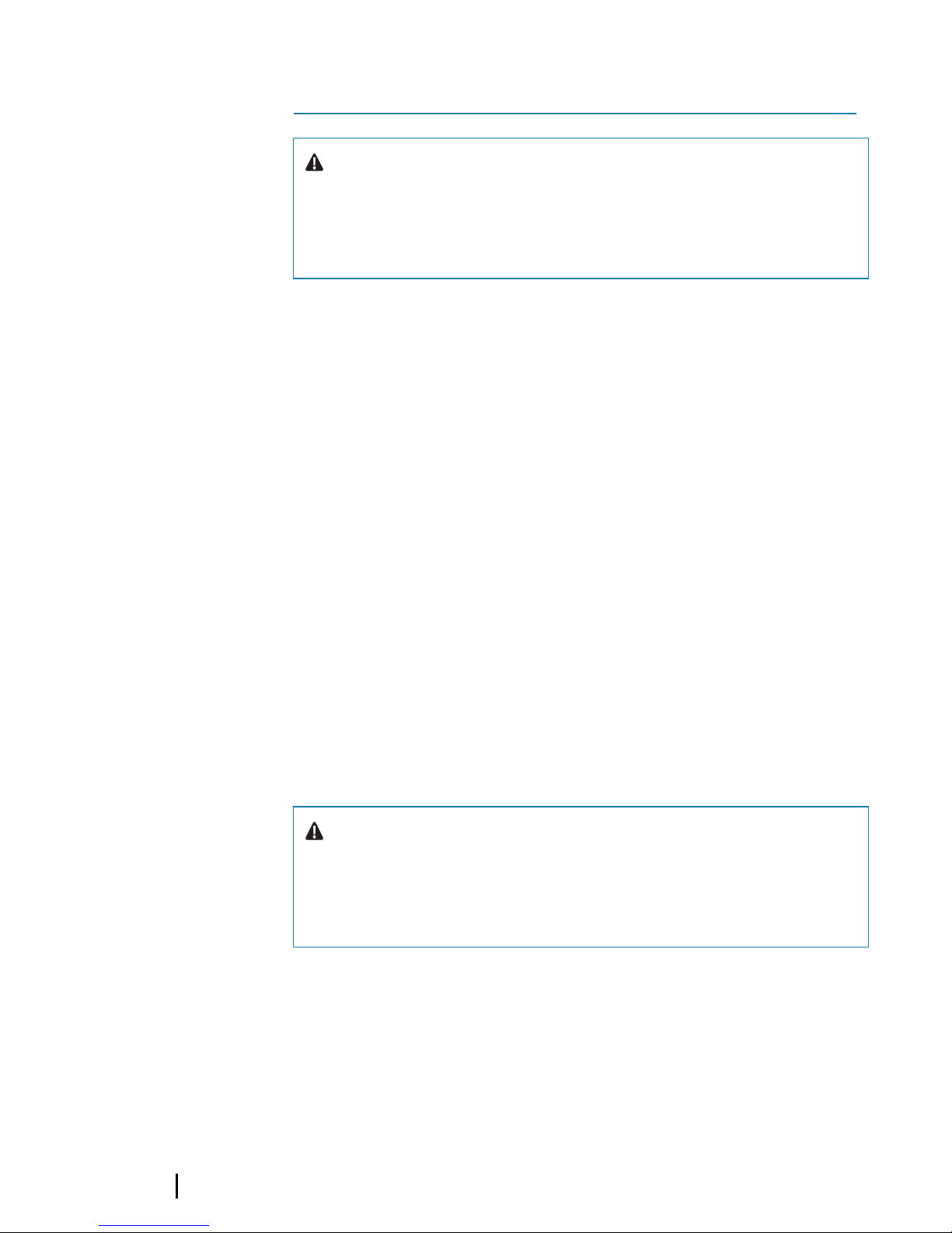
Warning: It is your sole responsibility to install and
use the instrument and transducer(s) in a manner that
will not cause accidents, personal injury or property
damage. Always observe safe boating practices.
Sonar performance: The accuracy of the sonar depth display can
be affected by many factors, including the type and location of the
transducer and water conditions. Never use this instrument to
gauge depth or other conditions for swimming or diving.
The choice, location, and installation of transducers and other
components of the system are critical to the performance of the
system as intended. If in doubt, consult your Navico dealer.
To reduce the risk of misusing or misinterpreting this instrument,
you must read and understand all aspects of the Installation and
Operation manuals. We also recommend that you practice all
operations using the built-in simulator before using this instrument
on the water.
Disclaimer: Navico Holding AS and its subsidiaries, branches and
affiliates disclaim all liability for any use of this product in a way that
may cause accidents, damage or that may violate the law.
Compliance Statements: The transducers comply with:
• CE under EMC Directive 2014/30/EU
• The requirements of level 2 devices of the Radio communications
(Electromagnetic Compatibility) standard 2017
Warning: The user is cautioned that any changes or
modifications not expressly approved by the party
responsible for compliance could void the user’s
authority to operate the equipment.
The relevant Declaration of Conformity is available at the following
websites under the product's section:
• http://www.lowrance.com/
• http://www.simrad-yachting.com/
1
2
Preface | Active Imaging transducers Installation
Manual

Trademarks: Lowrance® and Navico® are registered trademarks of
Navico. Simrad® is used by license from Kongsberg.
Navico products and features referenced: SideScan™
(SideScan), DownScan Imaging™ (DownScan), DownScan Overlay™
(DownScan Overlay), FishReveal™ (FishReveal), and Active Imaging™
(Active Imaging).
Copyright: Copyright © 2018 Navico Holding AS.
Preface | Active Imaging transducers Installation Manual
3

Parts included
The transom mounting bracket assembly parts and a hardware
mounting kit are included with the transducers. The transducer has
a cable attached with a 9 pin connector.
A
B
C
A Transom mount plate
B Transducer bracket mount plate
C Transducer with cable attached
Hardware mounting kit (included)
Transom mount screws #10x1-1/4" (2)
#10 flat washers for transom mount screws (2)
Bracket assembly bolt, M6 flanged head (2)
Bracket assembly flanged nut M6 (2)
Transducer attachment screws M4 (6)
Transducer attachment lock washers M4 (6)
Cable ties (2), used to secure the cable as needed
2
4
Parts included | Active Imaging transducers Installation
Manual

Required tools and supplies (not included)
Drill Phillips (cross-head) screwdriver
Drill bits Marine high-grade above- or below-
waterline sealant/adhesive compound
Parts included | Active Imaging transducers Installation Manual
5
Installation
Mounting options
The transducer can be mounted on the transom, jackplate, or step.
Use the following table to determine which mounting option is
best suited to your boat/installation preferences.
Ú
Note: When installing, keep the transducer on the protective
foam nest where the transducer is placed from factory.
Ú
Note: Before drilling any holes, ensure that holes are drilled in a
safe position. Ensure you do not drill into tanks, reservoirs,
hoses, or cables, etc. and that the holes will not weaken the
structure in any way.
Ú
Note: When mounting the transducer, make sure there is
nothing around the mounting location that could interfere with
its sonar beams.
Ú
Note: If mounting where the transducer comes out of the
water, for example when the boat is on plane, the sonar will not
work while the transducer is out of the water.
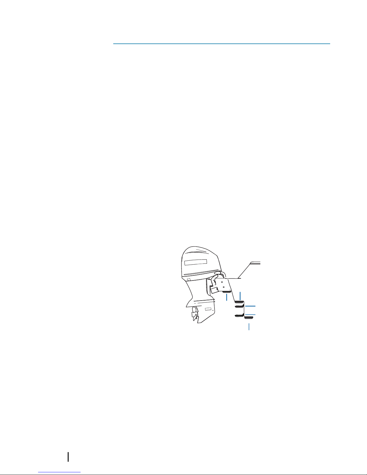
A
B
C
D
E
X
A Jackplate mount (Transom bracket)
B Direct Step mount (Flush bracket)
Requires separately sold Skimmer Flush mount kit
(part no. 000-12602-001)
C Step mount (Transom bracket)
D Transom mount (Transom bracket)
3
6
Installation | Active Imaging transducers Installation
Manual

E Do not mount the transducer under the hull or so
that it hangs down under the hull. The transducer
is better protected when mounted above the
bottom of the hull. There is less chance of
damage from obstructions in the water, or when
trailering and launching the boat.
Transducer mounting options
Transom mount
(Transom bracket)
Refer to "Transom
mount" on page 10
• Keeps transducer in the water when the
boat is on plane, allowing you to track
bottom at high speeds
• Transducer angle can be adjusted so it is
parallel with the water
• Transducer more likely to collide with
obstructions in the water and adds drag
to the boat
Step mount
(Transom bracket)
Refer to "Step mount
using the transom bracket"
on page 12.
• Transducer is not in the water when boat
is on plane; protects transducer and
prevents drag from transducer
• Transducer angle can be adjusted so it is
parallel with the water
• Sonar does not track bottom when
transducer comes out of the water
"Jackplate mount using the
transom bracket" on
page 15
• Transducer is not in the water when boat
is on plane; protects transducer and
prevents drag from transducer
• Transducer angle can be adjusted so it is
parallel with the water
• Allows you to mount transducer without
drilling holes in your boat
• Sonar does not track bottom when
transducer comes out of the water
Installation | Active Imaging transducers Installation Manual
7
Transducer mounting options
"Direct Step mount (Flush
bracket)" on page 13
Requires separately
sold Skimmer Flush
mount kit (part no.
000-12602-001)
• Transducer is not in the water when boat
is on plane; protects transducer and
prevents drag from transducer
• Transducer angle cannot be adjusted so
it is parallel with the water
• Sonar does not track bottom when
transducer comes out of the water
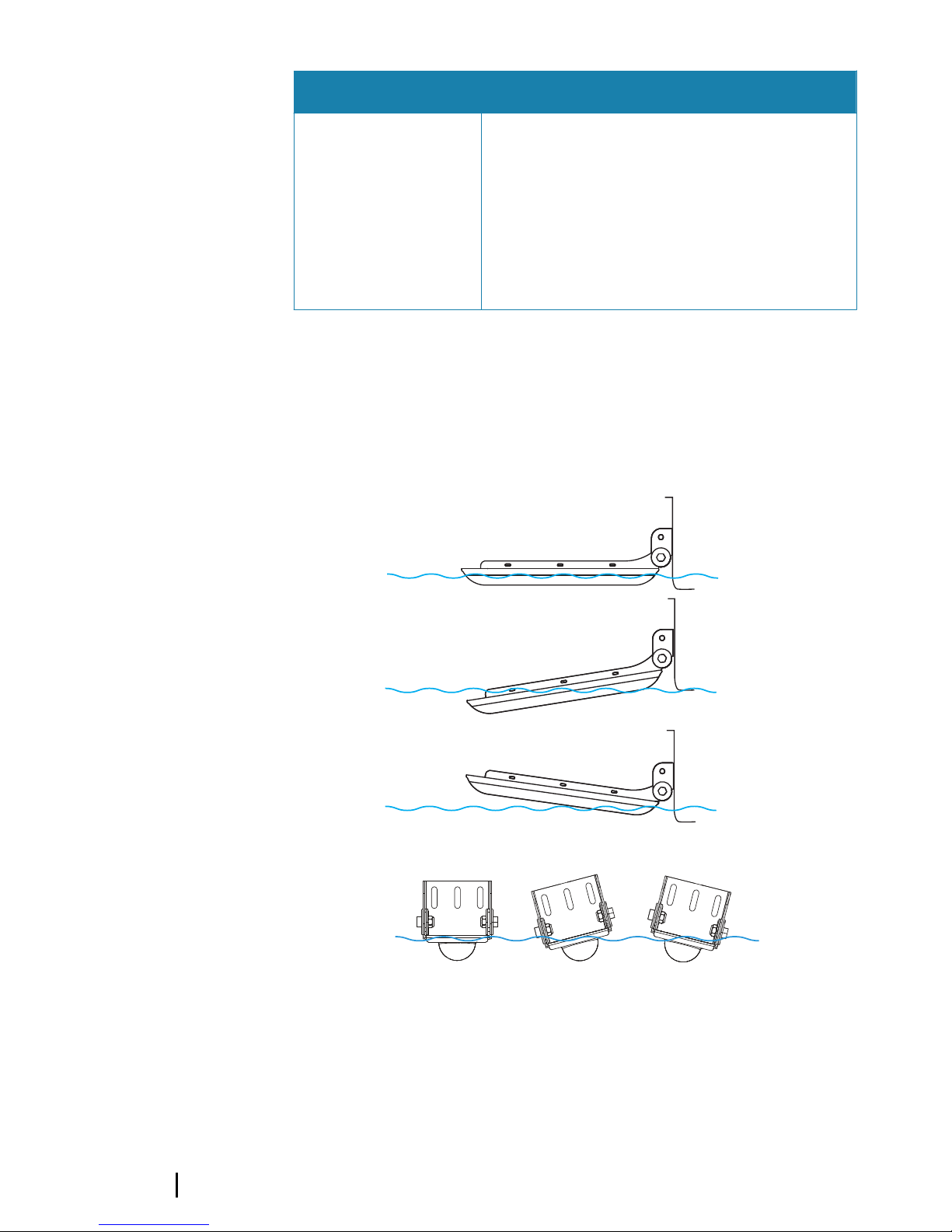
Transducer angle
After mounting the transducer, make sure the transducer is adjusted
so it will be parallel with the waterline in both the horizontal and
vertical axis when moving at trolling speed.
ü
û
û
ü
û
û
DownScan Overlay and FishReveal
The transducer should be installed within approximately 0.3 m (1 ft)
of the broadband sounder transducer to get optimum performance
from the DownScan Overlay and the FishReveal features. These
8
Installation | Active Imaging transducers Installation
Manual
features' performance could be degraded if the transducer is too far
away from the broadband sounder transducer.
Ú
Note: The Active Imaging 3-IN-1 transducer includes a
broadband sounder. As a result, the DownScan Overlay and
FishReveal broadband images work perfectly every time since
the images come from the same place.
< 0.3m (1ft)
Transom and step mount (Transom
bracket)
The transducer can be mounted to the transom or step with the
transom bracket. With these mounting options the transducer can
be in the water when you are on plane, or can be mounted so it is
only in the water when you are moving at trolling speed.
Transom and Step mount (fiberglass) supplies (not
included)
3 mm (1/8”) Drill bit (Transom
mount pilot holes)
Marine high-grade above- or
below-waterline sealant/
adhesive compound
Transom mount (aluminum hull) supplies (not included)
M4 Machine Screws Marine high-grade above- or
below-waterline sealant/
adhesive compound
Plastic isolating material such as King Starboard (prevents
corrosion between bracket and aluminum hull)
Installation | Active Imaging transducers Installation Manual
9

Transom mount bracket assembly
Ú
Note: Ensure the cable has been threaded through the bracket
before running the cable through the boat.
Transom mount
The transducer can be mounted on a transom bracket. With this
mounting option the transducer can be in the water when you are
on plane, or can be mounted so it is only in the water when you are
moving at trolling speed.
Ú
Note: Sonar does not track bottom when the transducer is out
of the water.
10
Installation | Active Imaging transducers Installation
Manual

1. Attach the transducer to the bracket mount plate using the 6
M4 attachment screws and M4 lock washers.
2. Loosely attach the transducer bracket mount plate to the
transom mount plate using M6 screws and nuts. Be careful to
run the cable between the bracket mount plate and the
transom mount plate before inserting the screws.
3. Choose a transducer location.
4. Place the bracket against the transom and then align the
bottom of the transducer with the bottom of boat. Use a pencil
to mark the pilot holes through the slots in the transom mount
plate.
5. Drill the pilot holes into the boat’s transom.
6. Apply a marine high-grade above- or below-waterline sealant/
adhesive compound to the pilot holes.
7. Align the transom mount plate screw slots over the pilot holes
and fasten the bracket to the transom using the supplied
screws.
8. To make adjustments to transducer position, loosen the screws
and slide bracket up or down.
9. Set the angle of the transducer, and tighten the M6 screws that
attach the transducer bracket mount plate to the transom
mount plate.
10. Route the transducer cable to the location where the display or
sonar module is installed.
11. Connect the transducer cable to the sonar port on the display or
sonar module.
After the transducer is connected and your boat is in the water,
ensure what is shown on the left and right side on your display
corresponds with what is on the left and right side of your boat. If
they are showing the opposite sides of what they should, turn on
the Flip Left/Right feature in your display unit to correct it. Refer to
your display unit's Operation manual for more information.
Installation | Active Imaging transducers Installation Manual
11

Step mount using the transom bracket
The transducer can be mounted on a transom bracket. With this
mounting option the transducer can be in the water when you are
on plane, or can be mounted so it is only in the water when you are
moving at trolling speed.
Ú
Note: Sonar does not track bottom when the transducer is out
of the water.
1. Attach the transducer to the bracket mount plate using the 6
M4 attachment screws and M4 lock washers.
2. Loosely attach the transducer bracket mount plate to the
transom mount plate using M6 screws and nuts. Be careful to
run the cable between the bracket mount plate and the
transom mount plate before inserting the screws.
3. Choose a transducer location.
4. Move the transducer bracket into the desired position and then
use a pencil to mark the pilot holes through the slots in the
transom mount plate.
5. Drill the pilot holes.
6. Apply a marine high-grade above- or below-waterline sealant/
adhesive compound to the pilot holes.
7. Align the transom mount plate screw slots over the pilot holes
and fasten the bracket to the transom using the supplied
screws.
8. To make adjustments to transducer position, loosen the screws
and slide bracket up or down.
9. Set the angle of the transducer and tighten the M6 screws that
attach the transducer bracket mount plate to the transom
mount plate.
10. Route the transducer cables through the bracket to the location
where the display or sonar module is installed.
12
Installation | Active Imaging transducers Installation
Manual

11. Connect the transducer cable to the sonar port on the display or
sonar module.
After the transducer is connected and your boat is in the water,
ensure what is shown on the left and right side on your display
corresponds with what is on the left and right side of your boat. If
they are showing opposite of what they should, turn on the Flip
Left/Right feature in your display unit to correct it. Refer to your
display unit's Operation manual for more information.
Direct Step mount (Flush bracket)
Flush mount bracket assembly
To mount the transducer directly to the step (Direct Step mount),
use the flush mount bracket (sold separately, part no.
000-12602-001).
Installation | Active Imaging transducers Installation Manual
13
Direct step mount installation
X
Ú
Note: Do not install the transducer under the hull.
You can mount the transducer in either direction; with the cable
coming out towards or away from the transom when installing with
the direct step (Flush bracket) mount. However, after the transducer
is connected and your boat is in the water, you need to check what
is shown on the left and right side on your display corresponds with
what is on the left and right side of your boat. If they are showing
opposite of what they should, turn on the Flip Left/Right feature in
your display unit to correct it. Refer to your display unit's Operation
manual for more information.
Ú
Note: Sonar does not track bottom when the transducer is out
of the water.
Direct step mount bracket and supplies (not included)
Pilot hole drill bit (Direct Step
mount pilot holes for selftapping metal screws)
Marine high-grade above- or
below-waterline sealant/
adhesive compound
Maximum 5 mm (#10 or 3/16”)
self-tapping metal screws
To direct step mount using flush bracket
1. Make sure the boat’s step is the same length or longer than the
transducer.
2. After selecting a mounting location, route the transducer cable
to the location where the display or sonar module is or will be
installed.
14
Installation | Active Imaging transducers Installation
Manual

3. Attach the transducer to the flush bracket using the M4
transducer attachment screws and lock washers.
4. Hold the assembly in the desired position. Use a pencil to mark
the pilot holes through the mounting holes on the flush
bracket.
5. Drill the pilot holes.
6. Apply a marine high-grade above- or below-waterline sealant/
adhesive compound to the pilot holes.
7. Align the flush bracket mounting holes over the pilot holes and
mount the flush bracket with the transducer to the step using
self-tapping metal screws (not supplied). Do NOT overtighten
the screws; otherwise you could strip out the fiberglass pilot
holes or crack the mounting holes on the bracket.
8. Connect the transducer cable to the sonar port on the display or
sonar module.
After the transducer is connected and your boat is in the water,
ensure what is shown on the left and right side on your display
corresponds with what is on the left and right side of your boat. If
they are showing opposite of what they should, turn on the Flip
Left/Right feature in your display unit to correct it. Refer to your
display unit's Operation manual for more information.
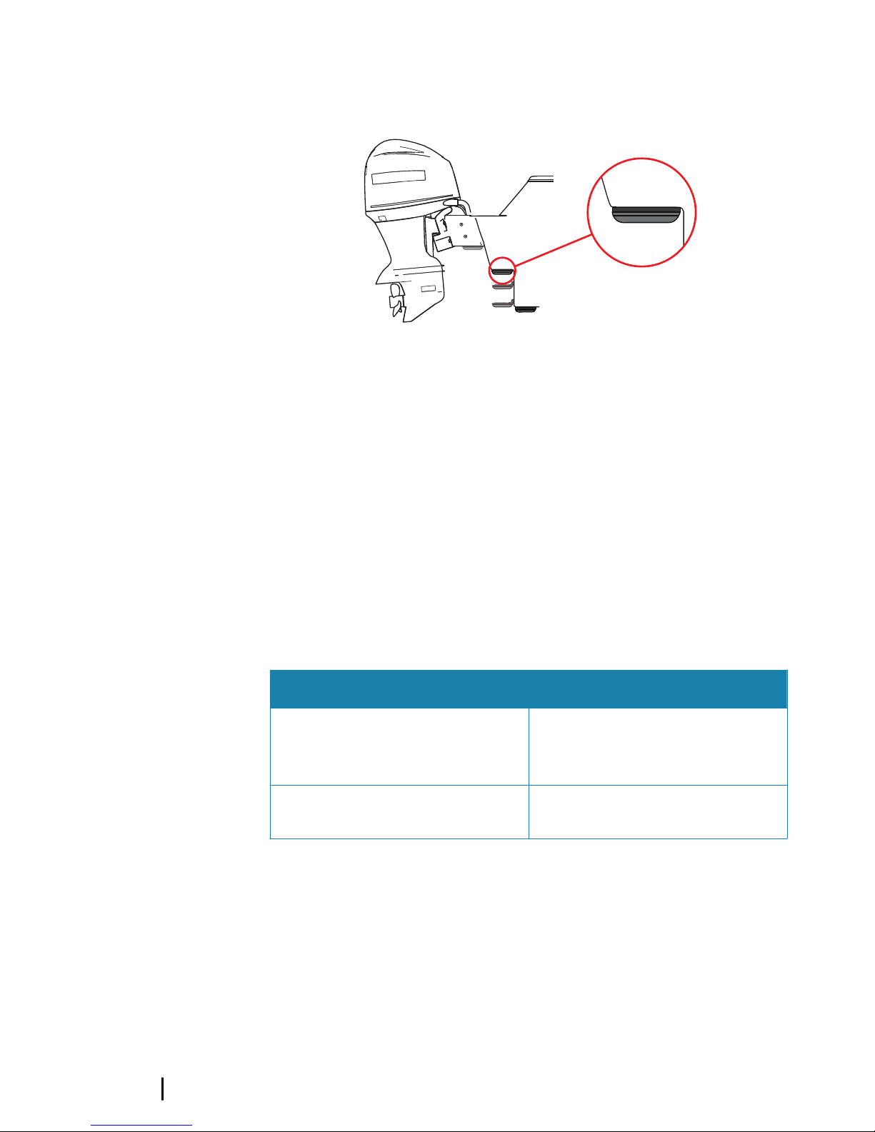
Jackplate mount using the transom bracket
The transducer transom bracket can be mounted inside or outside
of the jackplate by drilling through the jackplate and then running
bolts through the hinge hole in the side of the bracket into the
jackplate. The illustration above shows the transom bracket
mounted inside the jackplate.
Ú
Note: Sonar does not track bottom when the transducer is out
of the water.
Installation | Active Imaging transducers Installation Manual
15

Jackplate mount supplies (not included)
6 mm (1/4”) Drill bit (Jackplate
Mount)
M6 (1/4”) jackplate mount bolts
Warning: Before installing the transducer on the
jackplate, lower the jackplate to its lowest setting to
make sure there is enough clearance between the
jackplate, engine, transom, and the transducer. Lack of
clearance could damage the transducer when the
engine is all the way down.
1. Attach the bracket mount plate to the transducer using the 6
M4 attachment screws and M4 lock washers. Do not attach the
transom mount plate to the transducer bracket mount plate at
this time.
2. Choose a transducer location on the inside or outside of the
jackplate.
3. Adjust the jackplate up and down to make sure the transducer
will not obstruct jackplate movement.
4. Make sure nothing blocks the sonar beam on either side of the
transducer.
5. Move the transom mount plate into the desired position and
use a pencil to mark the holes through the hinge hole and the
top hole in the side of the bracket.
6. Using a 6 mm or equivalent drill bit, drill the holes into the
jackplate.
7. Depending where you want to mount it on the jackplate, slide
the transom mount plate inside the jackplate or hold it on the
outside of the jackplate and align the bracket holes with holes
you drilled in the jackplate.
8. Slide the M6 bolt into the top hole on the side of the jackplate
and the top hole of the transom mount plate.
9. Attach the M6 nut to the end of the bolt and tighten the nut.
10. Route the cable between the bracket mount plate (holding the
transducer) and the transom mount plate.
11. Hold the transducer mount plate (which is attached to the
transducer) so the bottom transom mount plate holes, the
hinge holes of the bracket mount plate (holding the transducer),
and the bottom holes you drilled in the jackplate are aligned. Be
16
Installation | Active Imaging transducers Installation
Manual

careful that the cable is properly routed between the transom
mount plate and the transducer mount plate.
12. Slide the second M6 bolt into the bottom hole you drilled on
the side of the jackplate, the transducer mount plate holes and
the transom mount plate holes.
13. Attach the M6 nut to the end of the bolt and tighten the nut.
14. Route the transducer cable to the location where the display or
sonar module is installed.
15. Connect the transducer cable to the sonar port on the display or
sonar module.
After the transducer is connected and your boat is in the water,
ensure what is shown on the left and right side on your display
corresponds with what is on the left and right side of your boat. If
they are showing opposite of what they should, turn on the Flip
Left/Right feature in your display unit to correct it. Refer to your
display unit's Operation manual for more information.
Installation | Active Imaging transducers Installation Manual
17

Dimensions
Transducer and transom mount bracket
250.0 mm (9.84”)
257.0 mm (10.11”)
280.0 mm (11.02”)
67.0 mm (2.63”)
79.0 mm (3.11”)
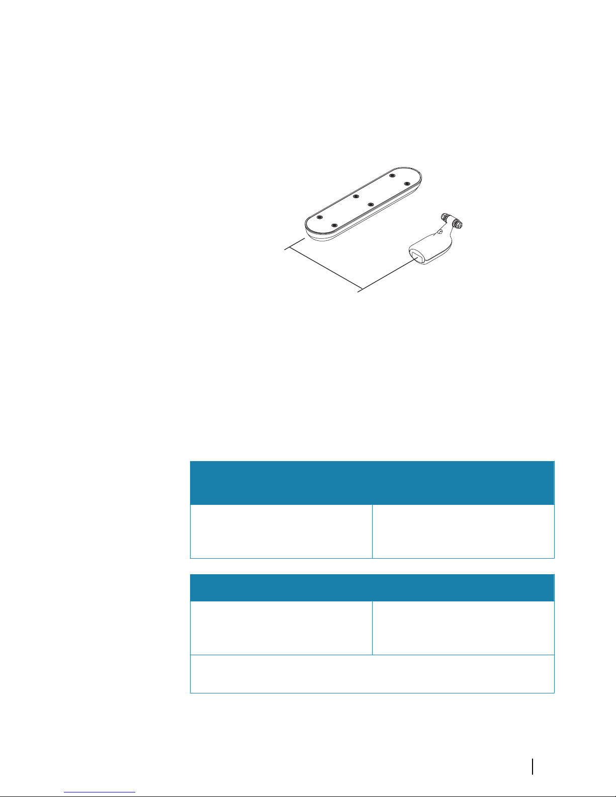
Active Imaging SideScan and Active
Imaging 3-IN-1 transducer cables
Ú
Note: The transducers come with either a 7.6 m (25 ft) cable or
a 1.83 m (6 ft) cable attached.
7.6 m (25’) or 1.83 m (6’)
26
mm (1”)
47.9 mm (2”)
24.5 mm
(0.97”)
A 26 mm (1”) diameter hole is recommended for cable connector
clearance.
4
18
Dimensions | Active Imaging transducers Installation
Manual

Parts and accessories
The most up-to-date parts and accessories are available at:
www.simrad-yachting.com or www.lowrance.com.
Active Imaging 3-IN-1 transducer (000-14489-001)
Includes the transducer with cable, transom mounting bracket
assembly and mounting screws, washers, and nuts.
Active Imaging SideScan transducer (000-14490-001)
Includes the transducer with cable, transom mounting assembly
and mounting screws, washers, and nuts.
Transom mount kit (000-12603-001)
Includes the transom mounting bracket assembly and mounting
screws, washers, and nuts.
Flush mount kit (000-12602-001)
Includes a 2 piece Flush mount mounting bracket. Use mounting
hardware supplied with the transducer.
10-FT 9-Pin Transducer Extension cable (000-00099-006)
5
Parts and accessories | Active Imaging transducers Installation
Manual
19

Technical specifications
Active Imaging 3-in-1 transducer
Environmental
Operating temperature -15°C to +55°C (+5°F to +131°F)
Storage temperature -30°C to +70°C (-22°F to +158°F)
Physical
Dimensions See "Dimensions" on page 18
Cable length 7.6 m (25 ft) or 1.8 m (6 ft)
Mounting options Transom, flush step, and
jackplate mounting
Number of pins 9 pins
Transducer
Output Traditional, SideScan imaging,
DownScan imaging and
temperature
Frequency • Traditional: 200 kHz/High
Chirp, 83 kHz/Medium Chirp
• SideScan: 455 kHz, 800 kHz
Max depth • Traditional: 305 m (1000 ft) at
200 kHz/High Chirp and 83
kHz/Medium Chirp
• DownScan: 91 m (300 ft)
• SideScan: 91 m (300 ft) side
range at 455 kHz, 46 m (150
ft) side range at 800 kHz
Operating speed • Traditional: 48 knots (55 mph)
• DownScan and SideScan: 9
knots (10 mph)
6
20
Technical specifications | Active Imaging transducers
Installation Manual

Active Imaging SideScan transducer
Environmental
Operating temperature -15°C to +55°C (+5°F to +131°F)
Storage temperature -30°C to +70°C (-22°F to +158°F)
Physical
Dimensions See "Dimensions" on page 18
Cable length 7.6 m (25 ft) or 1.8 m (6 ft)
Mounting options Transom, flush step, and
jackplate mounting
Number of pins 9 pins
Transducer
Output SideScan imaging, DownScan
imaging and temperature
Frequency 455 kHz and 800 kHz
Max depth • DownScan: 91 m (300 ft)
• SideScan: 91 m (300 ft) side
range at 455 kHz, 46 m (150
ft) side range at 800 kHz
Operating speed DownScan and SideScan: 9
knots (10 mph)
Technical specifications| Active Imaging transducers Installation
Manual
21

Troubleshooting tips
Troubleshooting tips
Transducer data not
displayed
• Check unit software is compatible
• Check transducer cable is connected to
display unit or sonar module (and it is
connected to the display unit)
• Check sonar is enabled in display unit,
refer to display unit Operator manual
• Check transducer is submerged in the
water
No depth Check range or turn on auto range
Data washed out /
same color
Turn down contrast; try different palettes
Left/right data
swapped on screen
Toggle the Flip Left/Right feature
No source is
displayed
• Make sure all switches are powered
• Ensure the sonar is enabled in display
unit, refer to display unit Operator
manual
• Check transducer cable is connected to
display unit
7
22
Troubleshooting tips | Active Imaging transducers
Installation Manual


*988-12309-001*
www.lowrance.com
www.simrad-yachting.com
 Loading...