

Page 1

Pub. 988-0151-361
Addendum I
LCX Sonar/GPS Series 25, 26,
110, 111 and GlobalMap
GPS
Series 6500, 6600, 7500, 7600
This addendum addresses the manuals for the units listed above (part
988-0151-311 for the LCX sonar/GPS units and 988-0151-331 for the
GlobalMap GPS units). Since the manuals were written, some changes
have occurred to these units. These changes will affect the installation
and operation of your unit, and include:
Map Dataset Choice Menu (LCX-26, 111; GlobalMap 6600, 7600)
• The Map Dataset Choice menu, featured only in the hard drive units,
now has a Lowrance MMC/SD option.
• The units without a hard drive (LCX-25, 110 and GlobalMap 6500,
7500) no longer have the Map Dataset Choice menu, as indicated in
their respective manuals.
Navigate Trail or Route
• The Navigate Trail/Route procedure has changed from the instruc-
tions listed in the manual. The procedure no longer includes the
step featuring the Navigate Option window.
Installation
• The LCX manual (part 988-0151-311) did not include MMC card in-
stallation instructions for the LCX-110 and LCX-111. This addendum describes those steps.
• Both the LCX series and the GlobalMap series have two communica-
tions ports to exchange NMEA 0183 position data with other devices. This addendum includes the wiring diagram for Com Port 2.
• The drawings showing unit dimensions and cable connections for the
LCX series (manual part 988-0151-311) have changed.
Map Dataset Choice menu
• The Map Dataset Choice menu, now featured only in the units with
the 20 gigabyte hard drive (LCX-26C HD and LCX-111C HD), has
five options: Standard, NauticPath, Fishing Hot Spots
Lowrance MMC/SD and Navionics
and Fishing Hot Spots Elite settings pull information from the
unit's hard drive, so there is no need to place a card into one of
. The Standard, NauticPath
Elite,
1
Page 2
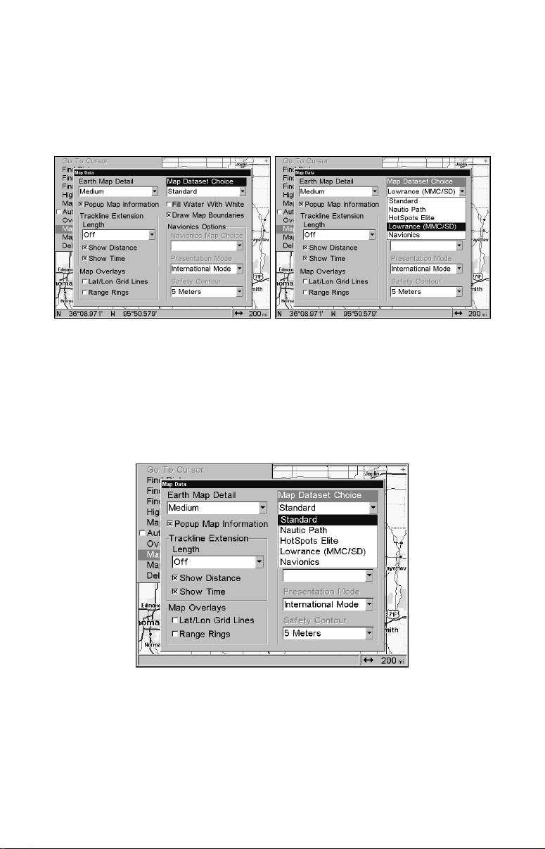
the MMC drawers or doors on the front of the unit. The other two
choices, Lowrance MMC/SD and Navionics, require an MMC, SD
or Navionics card. You must select the Lowrance MMC/SD setting to view information on a MMC or SD card, just as you must
use the Navionics setting to view information on a Navionics
card.
Map Dataset Choice menu (left) for the LCX-26C HD and LCX-111C HD
with the Lowrance MMC/SD option selected (right).
Caution:
Be sure and switch the Map Dataset Choice setting back to
Standard when you are finished with one of the other four chart
options. Otherwise, you will see only the basic background map
instead of the high detail custom map built into the unit's hard
drive.
Map Dataset Choice menu with Standard selected. The Standard option gives you access to the high detail map on the unit's hard drive.
NOTE:
The LCX-25C and LCX-110C do not have the Map Dataset Choice
menu. To access an enhanced detail custom map (made yourself with
MapCreate software), a FreedomMap, a NauticPath, Fishing
2
Page 3
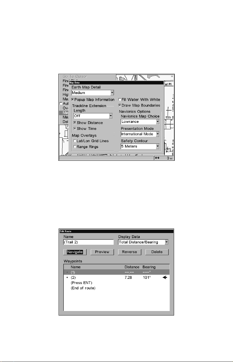
Hot Spots, Fishing Hot Spots Elite or Navionics chart, you must insert an MMC or SD card containing the mapping data into one of the
MMC drawers or doors on the front of the unit. Choose the default
Lowrance setting to view a MapCreate, FreedomMap, NauticPath,
Fishing Hot Spots, MMC or SD card. Only when a Navionics card is
loaded in the MMC drawer will you be able to select the desired
Navionics chart from the Navionics Map Choice menu.
The Navionics Options menu for the LCX-25C and LCX-110C with the
default Lowrance setting chosen.
Navigate Trail/Route procedure
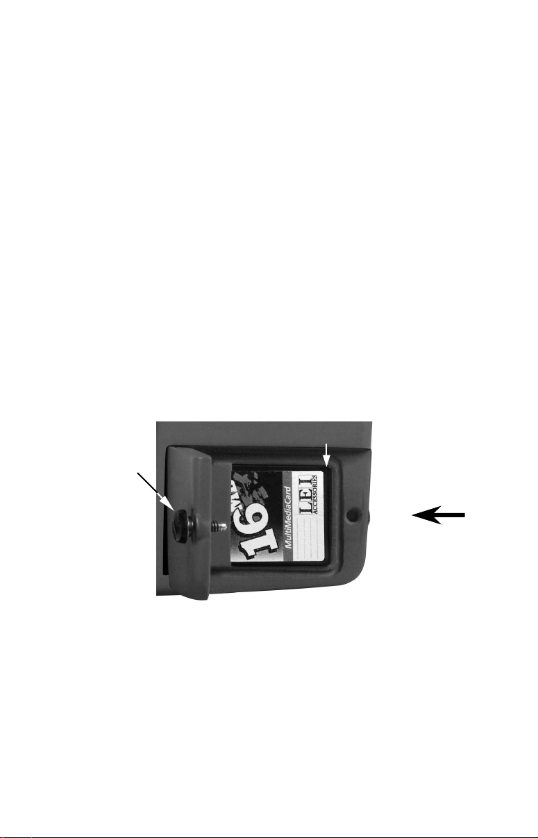
The Navigate Trail or Route procedure has changed. In the manual, it
says after pressing the Navigate button a Navigate Option window will
appear asking if you want to be prompted or directed to intermediate
waypoints along the trail or route. That will not be the case with your
unit.
Highlighting NAVIGATE and pressing ENT is the last command needed to
navigate a trail or route from the Edit Route screen.
3
Page 4
Here is the proper procedure for navigating a trail or route:
1. From the My Trails or Route Planning menu, press ↓ to the Saved
Trails or Saved Routes list.
To navigate a Trail:
2. Use ↑ ↓ to select a trail, then press
↓ to
NAVIGATE and press ENT.
ENT|→ ↓ to NAVIGATE|ENT. Press
3. Upon arrival at your destination, cancel navigation by pressing
MENU|MENU|↓ to CANCEL NAVIGATION|ENT.
To navigate a Route:
2. Use ↑ ↓ to select a route, then press
ENT| ↓ to NAVIGATE|ENT.
3. Upon arrival at your destination, cancel navigation by pressing
MENU|MENU|↓ to CANCEL NAVIGATION|ENT.
Installation
MMC or SD Memory Card Installation for LCX-110 & LCX-111
In the LCX-110 and LCX-111, the two MMC slots are located in compartments on the front of the case. The water-proof compartment doors
are located at the lower right corner. The following figure shows a
close-up of one compartment with the door opened.
MMC groove for card removal
Thumb
screw
Insert card face up,
this way
Memory card compartment with a 16 MB MMC card installed.
To remove an MMC or SD Card
1. Open the card compartment door by unscrewing the thumb screw.
The screw should only be finger tight. If it was over-tightened, use a
thumbnail, a coin or a screwdriver to open the door.
2. Use the ball of your finger or thumb and press down in the center of
the card, then drag the MMC from the slot. Or, use a thumbnail or fingernail to grab the groove in the bottom of the MMC and drag it out.
See the figure above for the groove location.
4
Page 5
To add an MMC or SD Card
1. Open the card compartment door.
2. Grasp the bottom of the MMC and push the top of the card into the
slot. Once the card is started, press down in the center of the card with
the ball of your finger or thumb and push the card all the way to the
left, until it is firmly seated in the slot.
3. Close the compartment door and fasten the thumb screw finger tight.
Com Port Wiring
The Com-2 communications port wiring diagram below was omitted
from the LCX manual (page 33) and the GlobalMap manual (page 16).
Com-1 can send or receive NMEA 0183 data; Com-2 can only send
NMEA 0183 data.
Blue (Transmit)
Com-2
To unit
Com-2 wiring to transmit NMEA position information
Shield (Ground)
to another NMEA-compatible device.
NMEA Receive
Ground
To Other
Device
In-Dash and Bracket Installation
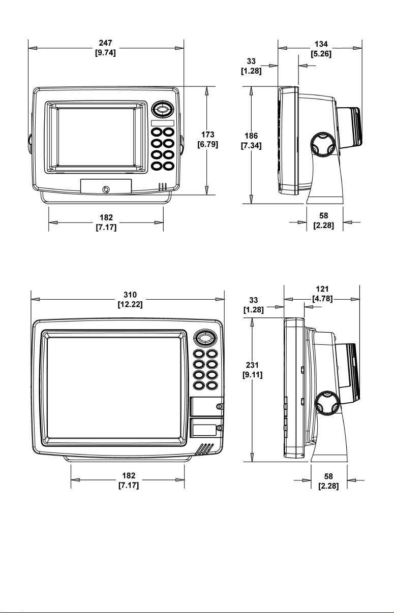
The in-dash mounting dimension drawing on page 38 of the LCX manual is only for the LCX-25 and LCX-26. No dash mount kit is available
for the LCX-110 and LCX-111.
In the LCX manual, the drawing on page 37 for an LCX-25 or LCX-26 is
incorrect. A similar drawing for the LCX-110 and LCX-111 was omitted. Both corrected drawings are shown on the following page.
Cable Connections
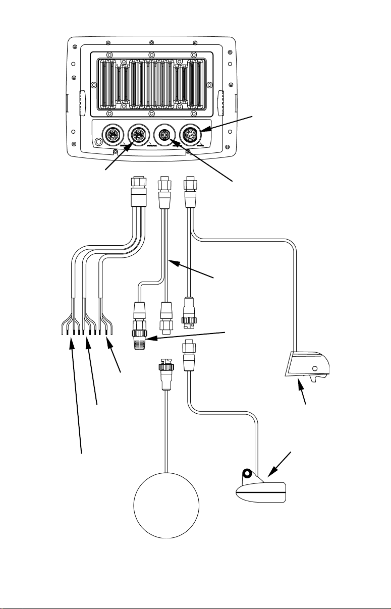
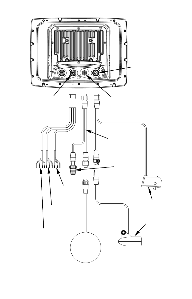
Following the mounted dimension drawings are illustrations showing
cable connections for the two case types in the LCX series. They correct
page 34 in the LCX manual.
5
Page 6
Millimeter
[Inch]
Front view (left) and side view (right) showing dimensions of the LCX-
25 and LCX-26 mounted on gimbal brackets.
Front view (left) and side view (right) showing dimensions of the LCX-
110 and LCX-111 mounted on gimbal brackets.
6
Page 7
Power/Data
socket
Sonar/GPS unit,
rear view
Sonar socket
Network
socket
LGC 2000 25'
extension cable
60-ohm
terminator
Power Cable
Power
Supply
Cable
NMEA 0183
Data Cable
NMEA 2000
SP-BL optional
speed sensor
Transducer
GPS
antenna
module
Cable connections, LCX-25 and LCX-26.
7
Page 8
Sonar/GPS unit,
rear view
Sonar socket
Power/Data
socket
Power
Supply
Cable
NMEA 0183
Data Cable
Network
socket
LGC 2000 25'
extension cable
60-ohm
terminator
NMEA 2000
Power Cable
SP-BL optional
speed sensor
Transducer
GPS
antenna
module
Cable connections, LCX-110 and LCX-111.
Printed in USA 031705
8
Copyright 2005 LEI
 Loading...