

Page 1

GlobalNav 200
INSTALLATION AND
OPERATION INSTRUCTIONS
TM
Page 2

Copyright © 1996, 1997 Lowrance Electronics, Inc.
All rights reserved.
GlobalNav 200™ is a trademark of Lowrance Electronics
Lowrance® is a registered trademark of Lowrance Electronics
WARNING!
USE THIS UNIT ONLY AS AN AID TO NAVIGATION. A CAREFUL
NAVIGATOR NEVER RELIES ON ONLY ONE METHOD TO OBTAIN
POSITION INFORMATION.
Never use this product while operating a vehicle.
CAUTION
When showing navigation data to a position (wa ypoint), this unit will show
the shortest, most direct path to the waypoint. It pro vides navigation data
to the waypoint regardless of obstructions. Therefore, the prudent navigator will not only take advantage of all available navigation tools when
travelling to a waypoint, but will also visually check to make certain a
clear, safe path to the waypoint is always available.
The storage temperature for your unit is from -4 degrees to +167 degrees Fahrenheit (-20 to +75 degrees Celsius). Extended storage temperatures higher or lower than specified will cause the liquid crystal display to fail. Neither this type of failure nor its consequences are covered
by the warranty. For more information, consult the factory customer service department.
All features and specifications subject to change without notice.
Lowrance Electronics may find it necessary to change or end our poli-
cies, regulations, and special off ers at any time. W e reserve the right to do
so without notice.
All screens in this manual are simulated.
Page 3

INTRODUCTION .......................................................................................................... 1
GETTING STA RTED .................................................................................................... 3
BATTERY INSTALLATION....................................................................................... 3
EXTERNAL ANTENNA ........................................................................................... 4
KEYBOARD.................................................................................................................. 4
OPERATION ................................................................................................................. 5
TURNING POWER ON ........................................................................................... 5
MENUS .................................................................................................................... 5
FINDING YOUR POSITION ..................................................................................... 5
COLD STA RT ..................................................................................................... 5
INITIALIZATION ................................................................................................. 6
POSITION/NAVIGATION DISPLAYS ...................................................................... 8
NAVIGATION SCREENS ................................................................................... 8
CDI...................................................................................................................... 10
PLOTTER ................................................................................................................ 11
PLOTTER CURSOR .......................................................................................... 11
PLOTTER OPTIONS.......................................................................................... 12
RECORD TRAIL ............................................................................................ 12
PLOTTER ORIENTATION ............................................................................. 12
CLEAR CURRENT PLOT TRAIL................................................................... 13
GRID LINES................................................................................................... 14
PLOTTER UPDATE ....................................................................................... 14
ICONS ................................................................................................................ 14
PLACE ICON - PRESENT POSITION .......................................................... 14
PLACE ICON - CURSOR LOCATION ........................................................... 15
ERASE ICONS .............................................................................................. 15
WINDOWS............................................................................................................... 16
REPROGRAM WINDOW GROUPS.............................................................. 17
RESET GROUPS .......................................................................................... 18
SATELLITE INFORMATION SCREEN.......................................................... 19
CLOCK........................................................................................................... 19
CLOCK ALARM ............................................................................................. 20
TIMERS ......................................................................................................... 20
REPROGRAM BOXES ............................................................................................ 21
WAYPOINTS ............................................................................................................ 22
SAVING YOUR PRESENT POSITION (QUICK SAVE) ..................................... 22
SAVING CURSOR POSITION........................................................................... 22
SAVING YOUR PRESENT POSITION .............................................................. 23
EDIT WAYPOINT LAT/LON................................................................................ 24
WAYPOINT NAMES ........................................................................................... 24
MOVE A WAYPOINT .......................................................................................... 25
DISTANCE BETWEEN WAYPONTS ................................................................. 26
WAYPOINT OPTIONS ....................................................................................... 26
DELETE A WAYPOINT ...................................................................................... 27
ROUTES .................................................................................................................. 27
CREATE A ROUTE ............................................................................................ 27
SELECT WAYPOINTS FOR ROUTE ............................................................ 28
FINISHING THE ROUTE ............................................................................... 29
DELETE A WAYPOINT FROM ROUTE ........................................................ 29
WAYPOINT DETAIL....................................................................................... 29
FOLLOW A ROUTE ........................................................................................... 30
DELETE A ROUTE ............................................................................................ 31
NAVIGATION ................................................................................................................ 31
NAVIGATE TO A WAYPOINT .................................................................................. 31
NAVIGATE TO A CURSOR LOCATION .................................................................. 31
Page 4

NAVIGATING TO A WAYPOINT USING THE PLOTTER........................................ 32
CANCEL NAVIGATION ........................................................................................... 32
SYSTEM SETUP.......................................................................................................... 33
BACKLIGHT ............................................................................................................. 33
SOUND .................................................................................................................... 33
CONTRAST ............................................................................................................. 33
UNITS OF MEASURE ............................................................................................. 34
NMEA/DGPS ........................................................................................................... 34
NMEA OUTPUT ................................................................................................. 36
DGPS.................................................................................................................. 36
SERIAL COMMUNICATION SETUP ................................................................. 37
RESET OPTIONS ................................................................................................... 37
RESET GROUPS .................................................................................................... 37
SYSTEM INFO ........................................................................................................ 37
GPS SETUP ................................................................................................................. 38
COLD STA RT........................................................................................................... 38
POSITION FORMAT ................................................................................................ 39
DATUM ..................................................................................................................... 40
PCF ....................................................................................................................... 41
POSITION PINNING ............................................................................................... 42
ALARMS ....................................................................................................................... 42
MESSAGES .................................................................................................................. 43
SIMULATOR ................................................................................................................. 44
STA RTING POSITION ............................................................................................. 44
USER ARROW KEYS TO STEER .......................................................................... 44
DEFINITION OF TERMS/ABBREVIATIONS ............................................................... 45
WINDOW GROUPS ..................................................................................................... 46
LIST OF DATUMS ........................................................................................................ 48
WARRANTY STATEMENT ........................................................................................... 53
HOW TO OBTAIN SERVICE - INTERNATIONAL ...........................INSIDE BACK COVER
HOW TO OBTAIN SERVICE - U .S.A. ONLY..................................................BACK COVER
Page 5

INTRODUCTION
Welcome to the e xciting world of GPS! Whether you’ re a first-time user or
a professional navigator, you’ll find the GlobalNav 200 is a full-featured
GPS receiver at a price that was impossible just a few years ago. The
Rockwell® receiver built inside has 12 channels that will track all of the
satellites that are in view of your location. It’ s acquisition time and tracking
ability are second to none in its class.
The Global Positioning System (GPS) w as developed by the United States
Department of Defense as a 24-hour a day, 365 days a year global navigation system for the military. Civilian availability was added with less
accuracy using the same satellites. Twenty-f our satellites orbit the Earth.
Three of these satellites are spares, unused until needed. The rest virtually guarantee that at least four satellites are in vie w of anyplace on Earth
at all times.
The system requires three satellites in order to determine a position. This
is called a 2D fix. It takes four satellites to determine both position and
elev ation, (your height abov e sea le v el - also called altitude.) called a 3D
fix.
Remember, the unit must have a clear view of the satellites in order to
receiver their signals. Unlike radio or television, GPS works at very high
frequencies. The signals can be blocked easily by trees, buildings, even
your body. Fortunately, they do travel through glass and plastic, so your
receiver will work in the car, if it has a clear vie w of the satellites through
the windshield or side windows. Let someone else drive if you use it in a
car or other vehicle.
Never use this GPS receiver while operating a vehicle!
The first time you use this unit, walk outside and turn it on in your backyard, an open field or park. Once it locks onto the satellites, you can experiment with it around buildings and trees. This will give you some idea
of its sensitivity to blockage.
Like most GPS receivers, this unit doesn’t have a compass or any other
navigation aid built inside. It relies solely on the signals from the satellites
to calculate a position. Speed, direction of travel, and distance are all
calculated from position information. Theref ore, in order for it to determine
direction of travel, you must be moving and the faster, the better. This is
not to say that it won’t work at walking speeds - it will. There will simply be
more “wandering” of the data sho wn on the displa y.
1
Page 6

S/A - What is it?
Another factor that greatly influences the receiver’s ability to deter mine
position is SA. The United States government intentionally degrades the
satellites signal for civilian users. They introduce small errors into the
satellite’s signals that makes the GPS receiver less accurate. These errors are called selective av ailability , or SA. How bad is it? The y guarantee
that the position reported by a GPS receiver that meets their specifications is within 100 meters horizontally and 150 meters vertically 95% of
the time. (The position can be better than that or worse than that the other
5% of the time.) In other words, the position shown on your receiver is
within 100 meters of your actual position, 95% of the time. That’s o ver 300
feet! Not exactly pinpoint accur acy, but then few people need positioning
accuracy greater than this. However, if you do want better performance,
(and who doesn’t?) many manufacturers (including Lo wrance) sell a DGPS
receiver that attaches to your GPS receiv er . The DGPS system transmits
correction signals that nullify the effects of SA. The DGPS receiver takes
signals from these land-based transmitters and gives them to the GPS
receiver which then uses them to show a more accurate position. The
ironic part is the federal government implemented SA and is also operating many DGPS transmitters. (You can use the signals from all of the
Coast Guard DGPS stations for free, b y the wa y.) The downside to this is
it requires another piece of electronic gear (the DGPS receiver) which
usually isn’t small enough to carry with you, but will work nicely on a
vehicle. And you ha ve to be close enough to a station to receive the DGPS
signals.
Don’t Get Lost
Generally, you find that using your GPS receiver without DGPS is both
easy and amazingly accurate. It’s easily the most accurate method of
electronic navigation available to the general public today. Remember,
however that this receiver is only a tool. Always have another method of
navigation available, such as a chart or map and a compass. It’s a good
idea to carry spare batteries with you, especially if you’re venturing into
unknown territory .
Also remember that this unit will always show navigation information in
the shortest line from your present position to a waypoint, regardless of
terrain! It only calculates position, it can’t know what’s between you and
your camp, f or example. It’ s up to you to saf ely navigate around obstacles,
no matter how you’re using this product.
2
Page 7
GETTING STARTED
Po wer
This unit operates from four AA batteries, or one DURACELL® NiMH
rechargeable battery, or from 5 to 16 volts DC using a CA-2 external
power cable (not included). If the power cable is used, the unit automatically switches to it if the external pow er is greater than the battery voltage.
If for any reason the e xternal power fails, the unit automatically switches
to the batteries.
BATTERIES
The unit requires four AA batteries. W e recommend you use alkaline batteries for the best trade-off between battery life and cost. However, you
can use nickel-cadmium (ni-cad), or lithium batteries. You can also use
rechargeable alkaline batteries such as RayOVac® Renewals®. With the
exception of lithium, none of the abov e batteries will last as long as standard alkaline batteries. We recommend DURACELL® brand, but others
will work. Do not use “heavy-duty” batteries or any type other than the
ones listed above. Do not mix different types of batteries. (For example,
don’t use both alkaline and ni-cad batteries at the same time.)
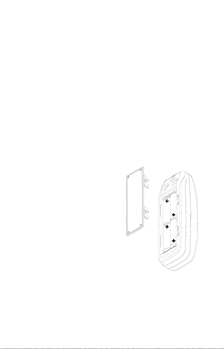
Battery Installation
First turn the unit so that its back is facing
you. Push the two tabs to the left and remove the battery cover as shown at right.
Install the batteries according to this diagram. (There’s a decal in the battery compartment showing the correct polarity,
also.) Replace the battery compartment
cover and the unit is ready f or use.
NiMH Battery
The DURACELL® DR-121 nickel-metal
hydride (NiMH) battery replaces the four
standard batteries. It is sold as an accessory , model BR-1 which includes a charger
custom designed for the DR-121. The battery never needs to be removed from the
unit, since the charger connects to the GPS receiver and charges the
DR-121. You can even use the receiver while the battery is charging!
To install the NiMH battery, remove the battery cover and place the battery into the compar tment as shown on the next page. It will only fit one
way, so if it’s difficult to install, simply turn it over and drop it into place .
3
Page 8
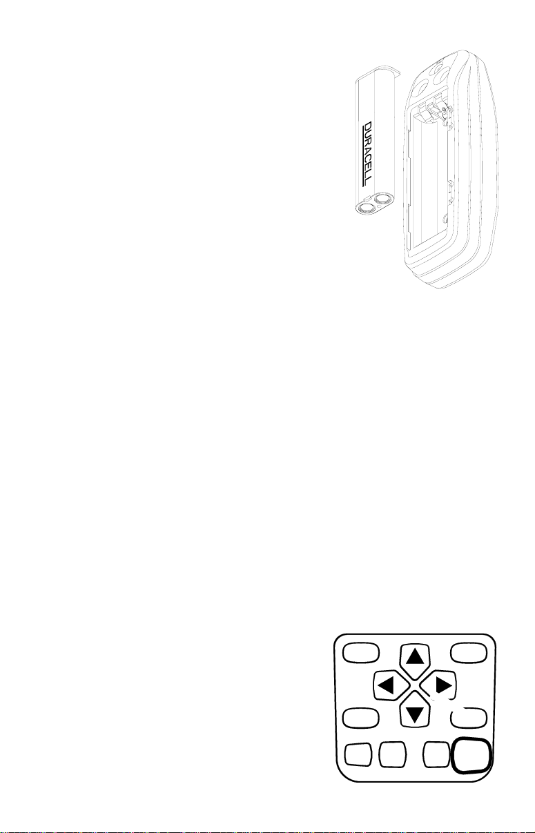
Replace the compartment cover and follow the
charging instructions included with the BR-1.
(Note: The DR-121 is the only battery that can
be recharged in this unit! Using the external
power cable alone does not charge the battery! You must use a charger supplied b y Lowrance in order to charge the battery . Also, this
charger will only charge a DR-121. It will not
charge any other type of battery , including nicads or rechargeable alkallines.)
External Antenna
Although this GPS receiver is extremely sensitive, it can be used in locations where the
built-in antenna simply cannot receive signals
from enough satellites. A second connector on the back of the unit is for
an external antenna. The Lowrance model EA-2 antenna plugs directly
into this connector. Other antennas ma y work. If y ou use an antenna other
than Lowrance, it will need to be a passive antenna. This unit does not
supply power to the antenna.
KEYBOARD
The keyboard has twelve keys. The arrow keys are tied to most of the
features, letting you easily mo ve the plotter’ s cursor , navigate through the
menus, make selections from menus , and other tasks.
The WPT k ey lets you create , sav e, and recall wa ypoints and routes. The
P A GES key s witches the unit between the three major displays: windows ,
navigation, and plotter . To select different features , or to modify functions,
press the MENU key. The Z-IN and Z-OUT keys zoom-in and zoom-out
your view on the plotter screen. The ENT
and EXIT keys let you enter or er ase selections. The PWR key tur ns both the Global-
P A GES
WPT
Nav 200 and it’ s lights on and off .
Note: To prevent an accidental power shut-
down, you must hold the PWR ke y down for
MENU
EXIT
a few seconds in order to turn the unit off.
ZIN ENT
ZOUT
4
PWR
Page 9
OPERATION
Turning Power On
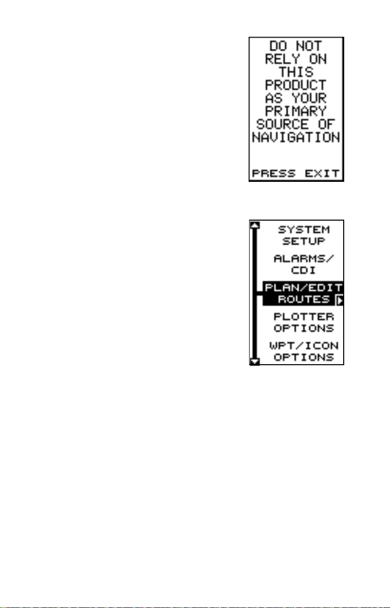
To turn the GlobalNav 200 on, simply press the
PWR key. A screen similar to the one at right appears. Read the message on the screen, then
press the EXIT key to erase it. The GlobalNav
200 is now ready for use.
MENUS
Most of the GlobalNav 200’s adjustments and features are found on
“menus”. Pressing the MENU key lets you view
the menus. Different menu items are added to the
basic list, depending on which page (plotter, navigation, or windows) the unit is on. This gives you
the features that are specific to the page you are
on, but also has items that are used on all pages.
Pressing the up or down arrow keys moves the
black bo x to highlight different menus on the list.
Pressing the right arrow key selects the highlighted menu item.
To erase a menu, press the EXIT key.
Finding Y our Position
Cold Start
When the GlobalNav 200 is turned on for the very first time, it doesn’t
know where it is, nor what the local time or date is. If you tell it your position, time, and date, the unit should take less time to loc k-on to the satellites and give you a fix or position.
However, if you don’t want to push buttons at this time, that’s fine. The
GlobalNav 200 will lock onto the satellites and giv e you a position without
any input from you. This is called a “cold-start”. It simply means that the
unit is searching without help for the satellites that are in orbit. A cold-start
can take over tw o minutes to acquire enough satellite data to determine
your position, although it typically takes less time than that.
To use your GlobalNav 200, first make certain you have a clear view of
the sky, free from any obstructions such as trees or buildings. Also , don’t
5
Page 10
try to use it under a carport, covered boat dock, or inside a building. T urn
the power on, press the EXIT key to erase the opening message and
watch the display.
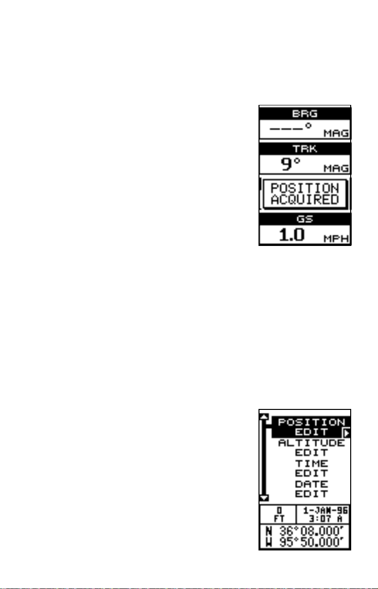
As you wait for the GlobalNav 200 to find your position, you’ll see numbers flashing on the display . Anytime you see flashing numbers, it means the GlobalNav 200 does
not have a position! Do not rely on an y data that
is flashing! Once the GlobalNav 200 locks on to
the satellites and finds your position, it shows a
“Position Acquired” message on the screen. It
also stores the satellite data in its memory. The
next time you use the unit, it should take much
less time to lock on.
That’s all y ou have to do to find y our position. Your
local time display may not be correct when the
cold start method is used. See the initialization
section for details on changing the time.
Finding Y our Position
Initialization
A cold-start as described above can take over two minutes to find your
position. A faster method is to initialize the GlobalNav 200 man ually . To do
this, first press the PWR key. Ne xt, read the message on the screen and
press the EXIT key to erase it. Now press the MENU key.
Press the up or down arrow keys until the “GPS SETUP” menu is highlighted. Now press the right arrow key. Next, using the down arrow key,
highlight the “INIT GPS” (initialize GPS) menu,
then press the right arrow key. The screen shown
at right appears.
This is the GPS initialization screen. The position, altitude, time, and date the GlobalNav 200 is
currently using to find the satellites is shown at
the bottom of this screen. Changing these v alues
to your local position and time will speed the position lock.
To change the position, press the right arrow key
while the “POSITION” box is highlighted. The
screen shown at right appears.
6
Page 11
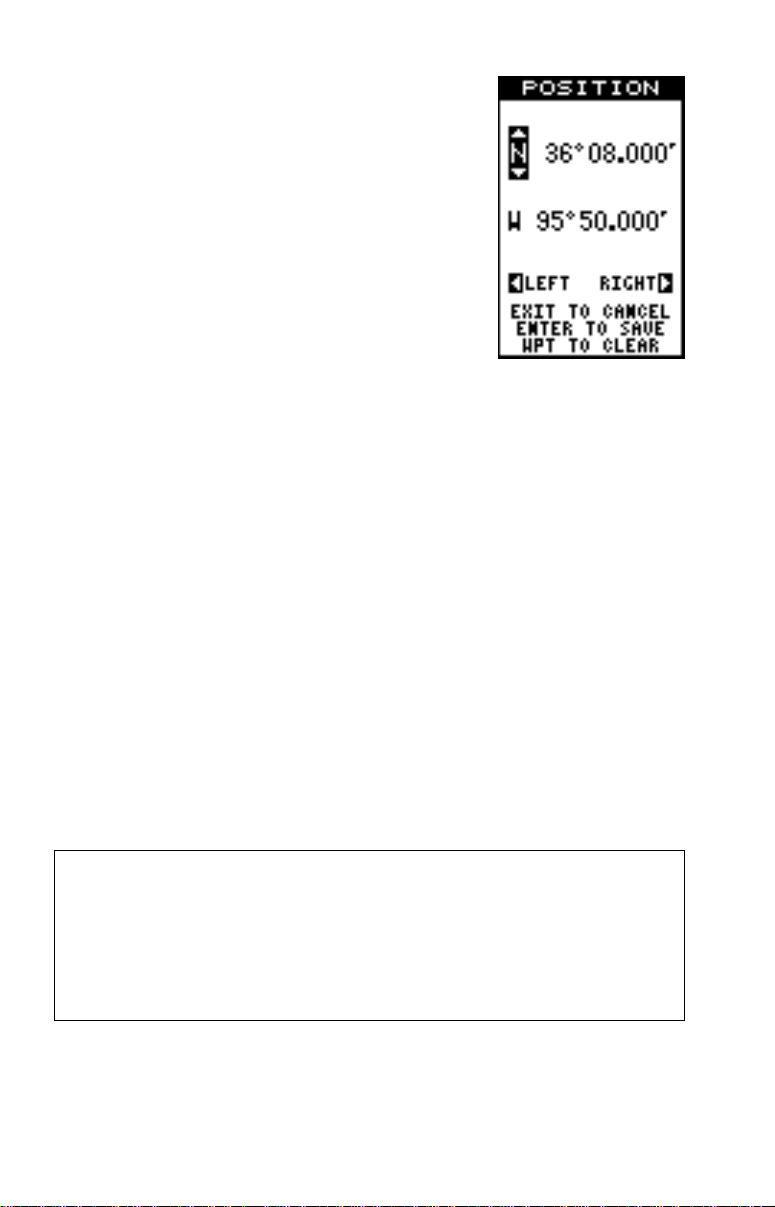
If your latitude is south, press the up or down arrow key to change it. If it is north, press the right
arrow key to mo ve the change box to the first number in the latitude. Now press the up arro w ke y to
increase the number or the down arrow k ey to decrease it. Once the first number in the latitude is
set, press the right arrow key once to mo ve to the
next number in the latitude.
Keep pressing the arrow k eys until the latitude and
longitude are set to your local position. (Note: This
position does not have to be v ery accurate. If y ou
can get it within one degree of your actual position, that will be fine.) When
it’s set, press the ENT key. The GlobalNav 200 accepts your entry and
returns to the GPS setup menu.
Now change the local time and date (if they’re incorrect) on this screen.
(Don’t worry about altitude.) When ever ything is acceptable, press the
EXIT key repeatedly to return to a page screen. The GlobalNav 200 will
instantly use the data you entered to find the satellites in the sky . (The unit
knows which satellites will be av ailable at the position, date, and time you
entered. Theref ore, it will only look f or those satellites, making the search
time much shorter than a cold start which looks for all of the satellites until
it finds three.)
Once the GlobalNav 200 finds and locks on to three satellites, it stops
flashing the numbers on the display. (Note: Altitude will still flash until the
unit locks on to the fourth satellite. It takes four satellites to determine
altitude.)
IMPORTANT!
If the data shown in digital numbers on any screen is flashing, it means
that data is invalid. DO NOT RELY ON ANY NUMBERS THAT ARE
FLASHING! Usually , this happens when the GlobalNav 200 has lost its
lock on the satellites. The data that is flashing w as the last known when
the unit lost its navigational capability .
DO NOT NAVIGATE WITH THIS UNIT UNTIL THE DATA STOPS
FLASHING!
7
Page 12
POSITION/NA VIGA TION DISPLAYS
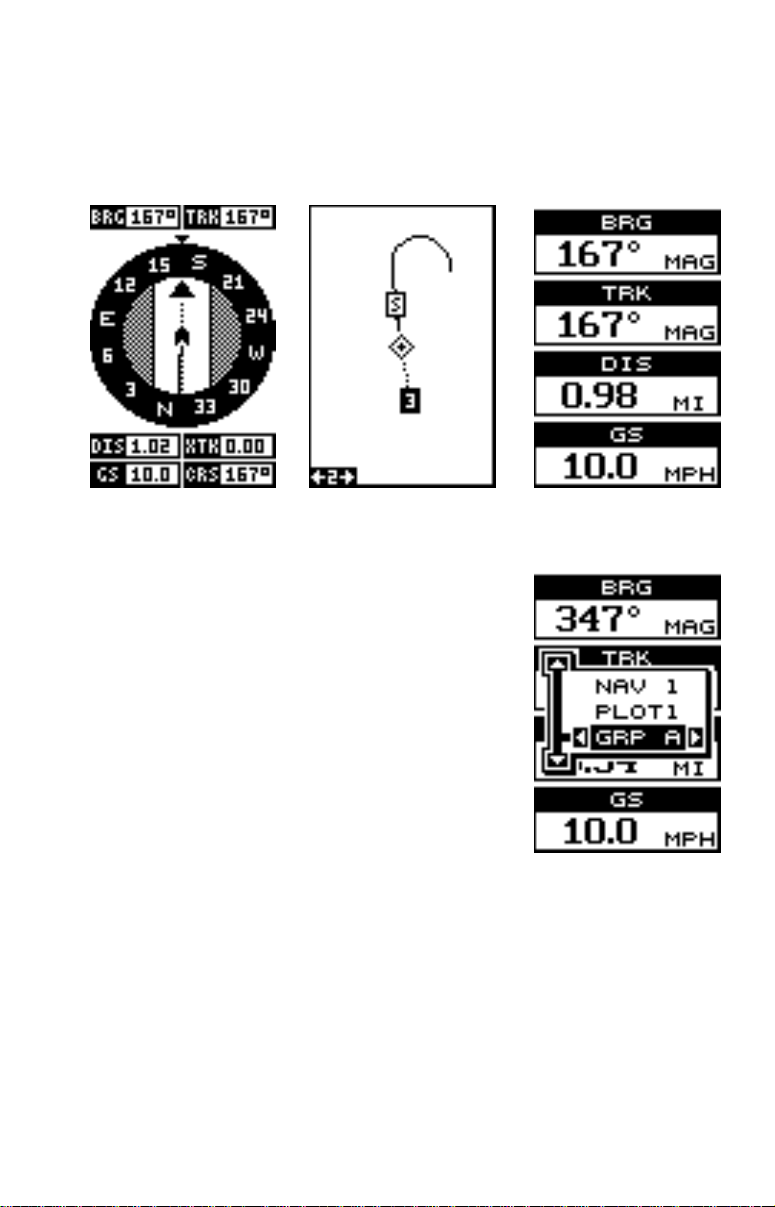
The GlobalNav 200 has navigation, plotter, and windows group pages.
These screens were designed to show data that is used most often. The
three default screens are shown belo w.
NAV-1 PLOT-1 GROUP A
To change screens, simply press the P A GES ke y .
A screen similar to the one at right appears. Now
press the up or down arrow ke ys to change pages.
(The windows display is shown as "GRP" (groups).
For example, Group A is the first windows group
on the PAGES menu.) Press the right arrow key
to see more screens on each page. When the desired screen appears, press the EXIT key to clear
the menu.
Note: For a list of abbreviations used on the displays, see the back of this man ual.
Navigation Screens
There are two navigation screens. Nav screen number one sho ws a graphical view of your trip , the other screen shows all navigation details in large
digital numbers. You can customize the navigation screens to sho w different data than the ones chosen by Lowrance. See the “Customize Screen”
section for more details.
8
Page 13
Nav Screen #1
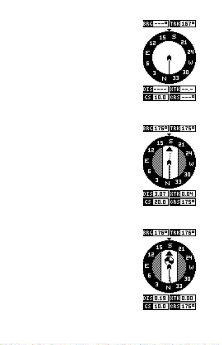
This screen is dominated by a compass rose (See
the screen at right.) Your position is in the center
of the circle, designated by an arrow that always
points straight up. Your track (direction of tra vel) is
indicated by an arrow pointing down toward the
compass rose at the top center of the screen. Your
track in digital numbers is also shown to the right
of the arrow. On the screen shown at right, the
track is 167°. The line extending behind the arro w
in the center shows your track history, or path
you’ve tra velled.
Your speed over ground or Ground Speed (GS)
shows in the digital box in the bottom left corner
of the screen. The screen looks like the one abo ve
when you’re not navigating to a waypoint. (See
page 28 for information on waypoint navigation.)
If you navigate to a waypoint, the screen looks
like the one at right.
The bearing to the destination waypoint is shown
in the upper left corner of the screen. Bearing is
also shown by the large arrow pointing up to the
compass. The bearing is 176° on the screen at
right.
NAV-1
The lines on either side of the present position
arrow show the cross track error range. In other
words, (using the screen abov e as an example) if
the arrow crosses the line on either side, you are
.10 miles to the left or right of the desired course.
A circle depicting your destination appears on the
screen as you approach the waypoint as shown
on the screen at right.
The digital box es on the bottom of the screen show
your distance to go to the destination (DIS), ground
speed (GS), cross track error (XTK), and course
(CRS).
Course (CRS) is the bearing from your starting
location to your destination. (Remember, course
9
Page 14
has nothing to do with your present position, except f or your starting location.) It’s shown as a dotted line on the NAV 1 display. This is sho wn as a
reminder so that if you deviate from your original course, you can easily
return to it. (A “course” is a proposed path over the ground. A “track” is
your actual path ov er ground.)
Nav Screen #2
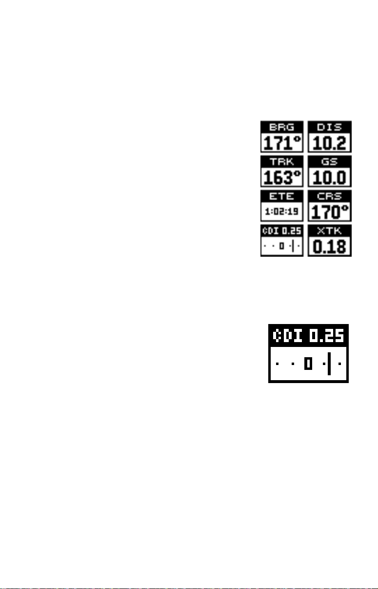
This navigation screen shows navigation inf ormation in large digital numbers. To view this screen,
press the PAGES key, then press the up arrow
key until the “NAV 1” label is highlighted. No w press
the right arrow key. A screen similar to the one at
right appears. Press the EXIT key to erase the
page menu.
This screen is composed of eight digital display
boxes, showing your track (TRK), and ground
speed (GS). The other bo xes show navigation data
when a waypoint is recalled, including bearing to
the waypoint (BRG), course (CRS), distance to
waypoint (DIS), estimated time en route (ETE),
and cross track error (XTK) along with a CDI. See below for more information on the CDI.
Course Deviation Indicator (CDI)
The CDI shows your distance to the left or right of
the desired course. You must recall a waypoint or
run a route to use the CDI. The ver tical line in the
center of the box shows the direction to the destination. For example , if you’ re travelling straight to wards
the destination, the line stays in the center of the
CDI. If you turn to the right, the line moves to the left, showing that the
destination is to your left.The CDI’ s range shows in the upper left corner .
The default is 0.25 mile. The dots at the far right and left side of the CDI
represent 0.25 mile. If the line is on either of these dots, then you are 0.25
miles off course. Remember , if the bar mov es to the left, then you are too
far to the
right
of the desired course line, and vice-versa. On the indicator
shown above , we are almost 0.2 mile to the left of the desired course. You
can adjust the CDI’s range through the “ALARMS/CDI” men u.
Using the CDI with the plotter helps you visualize your position in relation
to the course. The CDI is on several of the GlobalNav 200’s windows.
10
Page 15
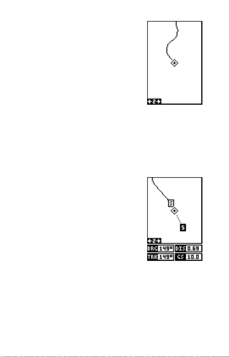
Plotter
The plotter lets you see your course and trac k from
a “birds-eye” view. If you’ve recalled a waypoint,
the plotter show your starting location, present
position, and destination. Ho wev er, y ou don’t have
to recall a waypoint to use the plotter.
To use the plotter, simply press the PAGES key,
then press the up or down arrow keys until the
“Plot” label is highlighted. Press the EXIT key to
erase the page menu. A screen similar to the one
at right appears. This is plot-1. The diamond flashing in the center of the screen is your present position. The solid line extending from the diamond is your plot trail, or path
you’ve tra velled. The plotter’s range is shown in the lo wer left corner of the
screen. In this e xample, the plotter’ s range is two miles from the left edge
of the screen to the right.
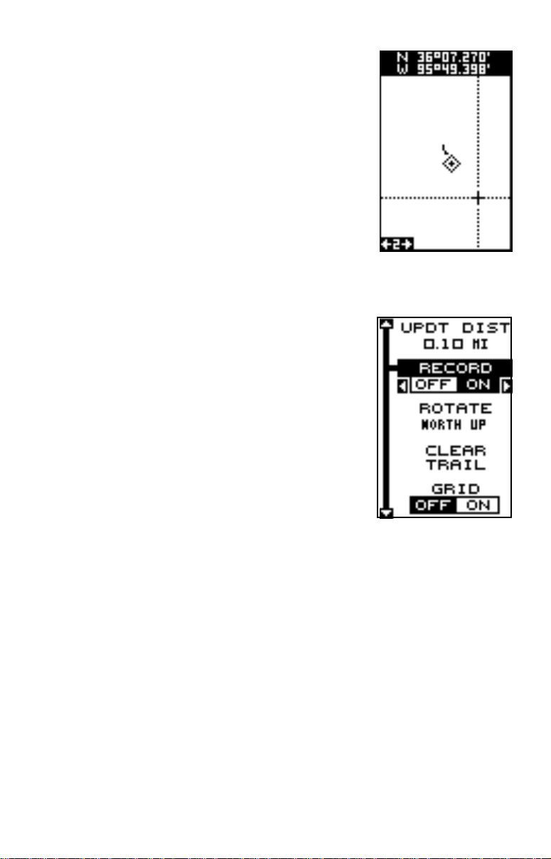
There are two different plotter screens available. Plot screen number 1
shows by default. Your current position displa ys at the center of the screen
as a cross surrounded by a flashing diamond.
T o vie w the other plotter screen, press the P AGES
key. Press the up or do wn arrow key to move the
black bo x to the "PLOT" label. Now press the right
arrow or left arrow ke y to select plot-2. This screen
(as shown at right) has navigation data display ed
at the bottom of the screen in digital numbers.
This data is active whenev er you’ve recalled a wa ypoint. Press the EXIT k ey to erase the page menu.
This screen shows bearing to waypoint (BRG),
distance to waypoint (DIS), ground speed (GS),
and track (TRK).
Use the Z-IN and Z-OUT keys to enlarge or reduce the plotter area. This
changes the plotter’s range . The available ranges are: 0.1, 0.15, 0.2, 0.3,
0.4, 0.6, 0.8, 1, 1.5, 2, 3, 4, 5, 6, 8, 10, 15, 20, 30, 40, 60, 80, 100,150,
200, 300, 400, 600, 800, 1000, 1500, and 2000 miles.
Cursor
Pressing an arrow key while the plotter is on sho ws tw o dotted lines that
intersect at your present position. These dotted lines are called a “cursor”
and have a v ariety of uses.
11
Page 16
You can move the cursor around the display by
pressing the arrow keys in the direction y ou w ant
it to move. This lets you vie w different areas of the
plotter, a way from y our present position. When it’ s
turned on, the zoom-in and zoom-out keys work
from the cursor’s position - not the present position, so you can zoom in on any detail, an ywhere
while navigating. The latitude/longitude of the cursor shows in the box at the top of the plot-1 screen
whenever the cursor is activated. The cursor is
also used to place and erase icons and waypoints .
Press the EXIT key to erase the cursor.
PLOTTER OPTIONS
The GlobalNav 200 lets you customize the plotter
using the “Plotter Options” menu. T o use this men u,
first press the MENU key, then use the up or down
arrow keys to highlight the “Plotter Options” label.
Finally, press the right arrow key. The screen
shown at right appears.
Record Trail On / Off
The line extending from the present position diamond on the plotter is call the plot trail. As each
dot on the trail is placed on the screen, it’s also
saved in memory. The plot trail recording can be
turned off, if desired. To turn it off, press the up or
down arrow ke y until the “Plot Tr ail” menu is highlighted and press the left arrow key.
Plotter Orientation
Normally, the GlobalNav 200 shows the plotter with north always at the
top of the screen. This is the way most maps and charts are printed on
paper. This is fine if you’ re always tr avelling due north. W aypoints you see
to your left corresponds to the left side of the plotter , to your right is shown
on the right side of the plotter, and so on. How ev er , if you tr av el any other
direction, the plotter doesn’t line up with your view of the w orld.
To correct this problem, the GlobalNav 200 has a track-up mode that
rotates the plotter as you turn. Thus, what you see on the left side of the
screen should always be to your left, and so on. It also has a course-up
mode that keeps the plotter at the same orientation as your initial bearing
to the waypoint.
12
Page 17
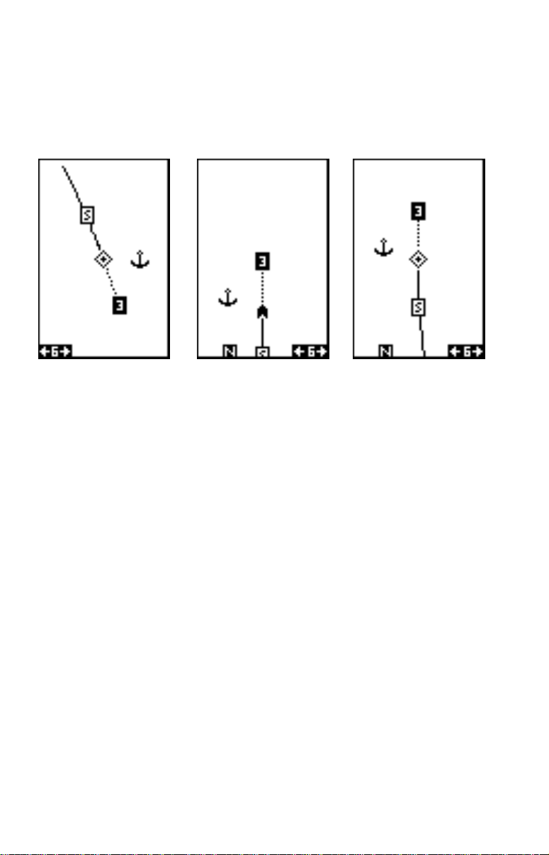
In the examples shown below , we're tra velling southeast (about 150° magnetic). In the north-up view , the present position indicator appears to mov e
towards the lower right corner of the screen. The anchor icon shown on
the right side of the screen is actually on our left. North is always at the
top center of this screen.
NORTH-UP MODE COURSE-UP MODE
TRACK-UP MODE
In the track-up view, the present position symbol (which has changed to
an arrow) mov es straight tow ards the top of the displa y. As y ou can see,
the anchor icon is now shown in its proper orientation - to our right. A "N"
shows to help you see which direction is north when the track-up mode is
on. Remember, in the track-up mode, the screen rotates as you change
direction. It alwa ys k eeps y our direction of tr avel (track) heading towards
the top of the screen.
In the course-up mode, the screen is locked into y our original bearing to
the recalled waypoint, regardless of y our track.
To select the desired mode, highlight the “ROTATE” label on the “Plotter
Options” menu, then press the left or right arrow keys until the desired
mode appears. Press the EXIT key to leav e this men u
Clear Current Plot Trail
The line extending from the present position diamond on the plotter shows
the path you’ve tak en, This is the plot trail. To erase the plot trail, highlight
the “ClearTrail” label on the Plotter Options menu, then press the right
arrow key. A message bo x appears, asking y ou if you really want to erase
the plot trail. Follow the directions on this message box. The GlobalNav
200 returns to the plotter screen with the plot trail erased from the screen.
13
Page 18
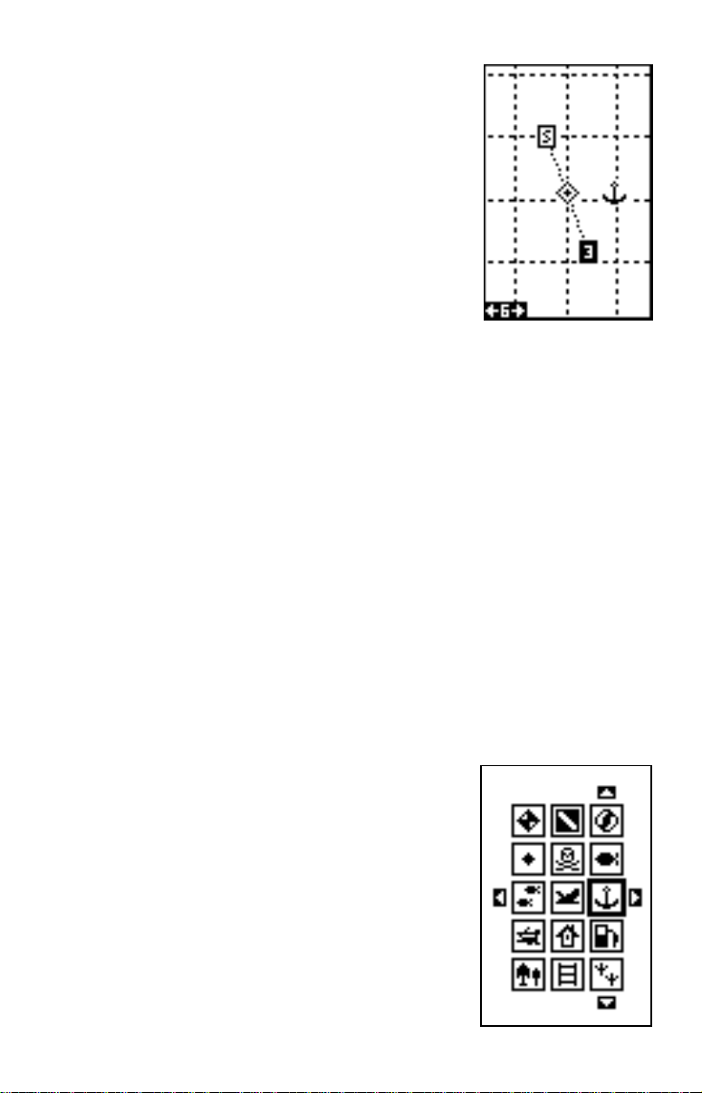
Grid Lines
The GlobalNav 200 can place grid lines on the
plotter to help you see your position, or the position of waypoints and icons.
T o do this , highlight the “Grid” label on the “Plotter
Options” menu, then press the right arrow key to
turn them on. Press the EXIT key to e xit this menu.
A plotter screen similar to the one at right appears.
The grid lines appear as vertical and horizontal
dashed lines.
GRID LINES
Plotter Update
The plotter places a dot on your trail as you mo ve . It determines when to
place a dot depending on either time or distance. By default, it places a
dot every three seconds.
T o change the update method from time to distance , highlight the “Update
By” label, then press the right arrow k ey . This moves the label from “TIME”
to “DIST”.
If you want to change the update time or distance, simply highlight either
the “UPDT RA TE” to change the update time or the “UPDT DIST” to change
the update distance, then press the left or right arrow keys until the desired setting appears. Press the EXIT k e y to er ase the plotter menu.
ICONS
The GlobalNav 200 has fifteen symbols or “icons” available. These icons
can be placed anywhere on the plotter screens. These can be used to
mark fishing or hunting spots, boat ramps, rest stops, or whatever. You
can place an icon at your present position, or at
the cursor location.
Place Icon - Present Position
To place an icon at your present position, simply
press the ENT key. The screen shown at right
appears. Use the arrow keys to move the black
box to the desired icon. Now press the ENT key.
The plotter screen appears with the icon you selected placed at your position when you first
pressed the ENT key, not your present position.
14
Page 19
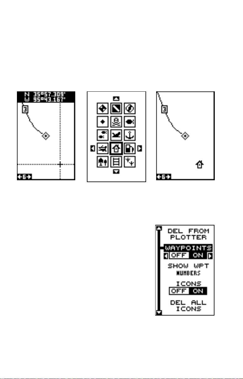
Place Icon - Cursor Location
To place an icon at cursor's location, first use the arrow keys to mov e the
cursor to the position that you want to place the icon. Next, press the ENT
key. No w select the desired icon using the arrow keys. When it's selected,
press the ENT key again. The plotter screen reappears with the icon at
the cursor's location. Press the EXIT key to erase the cursor. On the
screens shown above, the house icon was selected and placed at the
cursor location.
PLACE CURSOR ICON ON PLOTTER
PRESS ENT KEY
AND SELECT ICON
Erase Icons
To erase an icon from the screen, first press the
MENU key, then select the “WPT/Icon Options”
menu. A screen similar to the one at right appears.
There are three methods used to erase icons from
the screen. You can delete all of the icons, regardless of their position on the display, delete all
of the icons of a certain type, or selectively erase
individual icons. You can also simply turn all of
the icons off without erasing them.
To turn all of the icons off, without erasing them,
highlight the “ICONS OFF ON” label, then press
the left arrow key. T o erase all of the icons, highlight the “DEL ALL ICONS” menu, then press the right arrow ke y. A mes-
sage appears, asking you if you want to delete all icons. Press the right
arrow key to erase them. The unit returns to the plotter screen with all
icons deleted.
15
Page 20
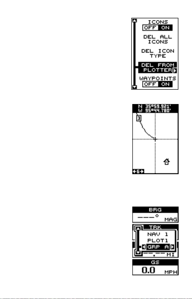
To remove only icons of a certain type, highlight
the “DEL ICON TYPE” label. Press the right arrow key. The icon selection menu appears. Use
the arrow keys to highlight the icon style that y ou
wish to erase. Press the ENT key when you’re
ready to erase the icons. A message appears,
asking you if you want to delete the icons of that
type. Press the left arrow k e y to er ase them. The
unit returns to the plotter screen with all icons of
the type you selected erased.
To remove only certain icons, highlight the “DEL
FROM PLO TTER” label. Press the right arrow key .
The unit returns to the plotter screen with the cursor centered on your present position as shown
at right. Use the arrow k eys to mo v e the cursor to
the icon on the map that you wish to erase. Press
the ENT key to erase the icon. If you wish to delete another icon, move the cursor ov er it and press
the ENT key . When you’ re finished, press the EXIT
key to erase the cursor.
WINDOWS
This feature giv es you 15 different groups of windows so you can use the best navigation display
for your situation.
T o use the windows f eature, press the P A GES key,
then highlight the “GROUP A” label as shown at
right. Group “A” is visible in the bac kground when
you switch to the windows groups. To view each
group, simply press the right or left arrow key while
the pages menu is showing. Each group shows in
the background as you press the arrow keys.
When you see the group you w ant to use, simply
16
Page 21
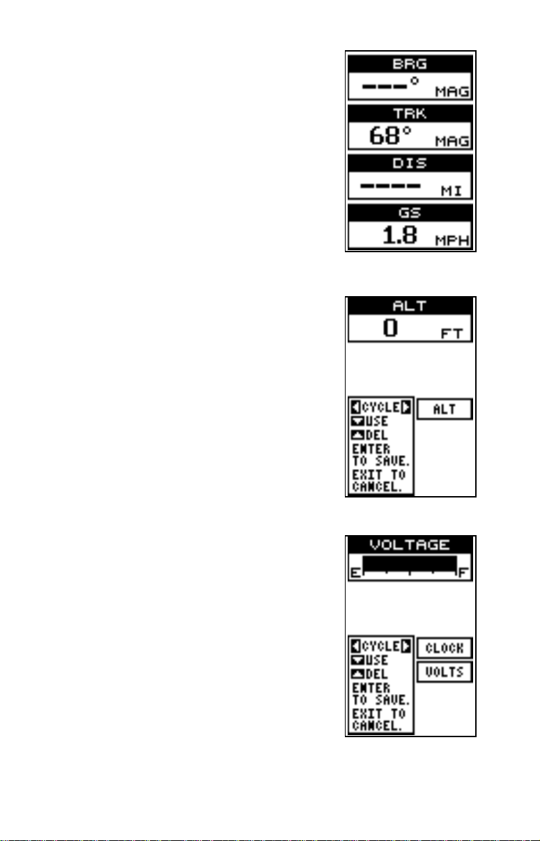
REPROGRAM WINDO W GROUPS
You can customize the window groups to meet
your own needs. The GlobalNav 200 gives you 35
different windows that can be rearranged into
many combinations.
To reprogram a group, first go to the pages menu
and select the group that you wish to change. In
this example, we’re reprogramming group “A”,
shown at right.
Next, press the MENU key, highlight the "Reprogram Groups" label and press the right arrow key.
A screen similar to the one shown at right appears.
The altitude window appears at the top of the
screen. To view a different window, press the left
or right arrow key. When the desired window
appears, press the down arrow key to select it. In
this example, we selected the digital clock. The
GlobalNav 200 will add this window to the selected group. It then shows the selected window’s
position, as shown at right. If you want to delete
this window from the group, simply press the up
arrow key.
The next window selected was the voltmeter.
Continue selecting windows in this manner until all
of the desired windows have been added to the
group.
17
Page 22
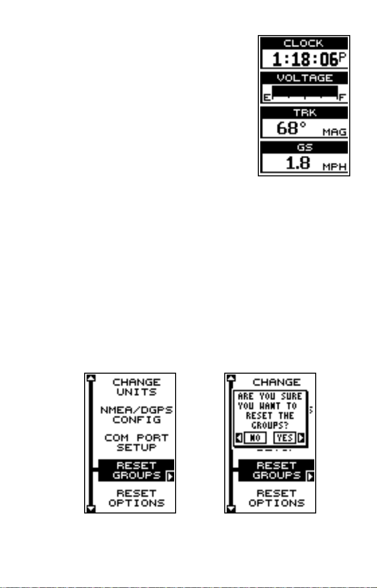
When the last window has been added, the
GlobalNav 200 returns to normal operation with
your reprogrammed group showing on the screen,
as shown at right.
RESET GROUPS
T o restore all windows groups to their f actory settings, first press the MENU
key, then highlight the “System Setup” label and press the right arrow k ey .
Now highlight the “Reset Groups” label on this menu. Press the right arrow key. A message appears, asking if you really want to do this. Press
the right arrow key to continue , or the left arrow k e y to e xit without resetting the groups.
18
Page 23
press the EXIT key to erase the pages men u.
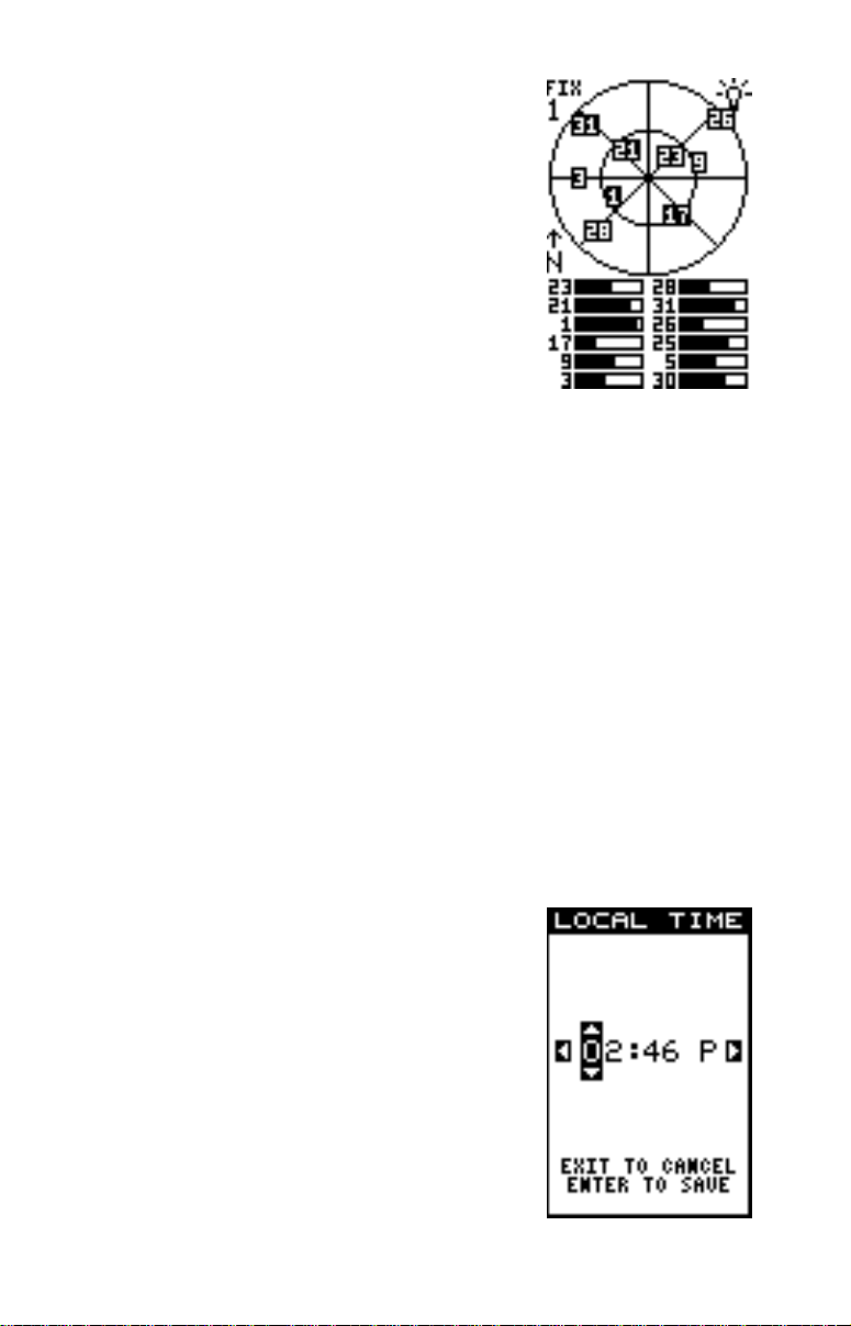
Satellite Information Screen (Group O)
This screen shows technical information about the
status of the GPS receiver . The receiver has twelv e
channels. Data for each channel is shown as bar
graphs on the right side of the display. Ev ery satellite in the constellation has a number assigned
to it, called the PRN. The bar graph is beside each
satellite’s number . The higher the bar on the graph,
the better the signal is being received from the
satellite.
Each satellite is also shown on the circular graph
at the top of the screen. This shows you not only which satellites are in
your area, but also their direction from your position, and their elevation
(distance above the horizon.) The small inner circle represents 45° abov e
the horizon and the large outer circle represents the horizon. A satellite is
straight above y ou when it is at the intersection of the horizontal and vertical lines that pass through the circles.
The “N” on the left center of the screen shows the direction of north relative to the satellite graph.
The FIX number in the top left of the screen shows the quality of fix. If the
FIX is 9, then it's the best you can get. A FIX of 1 is the worst. The light
bulb in the top right corner of the screen shows when the backlight is on.
CLOCK
Whenever a clock, timer, or alarm is showing on a display, new items
appear in the list when you press the MENU key. These items let you set
the clock’ s time , alarms, or the timers.
Set Local Time
If the time shown on the clock display is not your
local time, change it using the “Set Local Time”
function. To do this, press the MENU key , then highlight the “Set Clock” label. Press the right arrow
key. The screen at right appears.
Using the right and left arrow keys , move the blac k
box to the first number in the time that y ou want to
change. Now press the up or down arrow keys
until the desired number shows. Continue until the
time shown in the display is correct, then press
the ENT key. This enters the new time and erases
19
Page 24
the set local time menu.
Clock Alarm
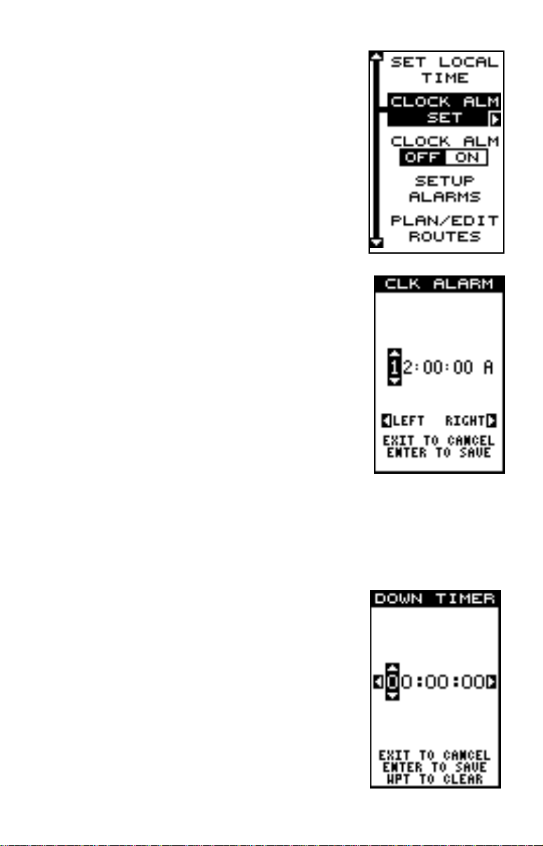
You can set the alarm by using the “Clock Alarm”
menu. T o set this alarm, press the MENU ke y while
group “J” is showing, then highlight the “Clk Alm
Set” label. Press the right arrow key. The screen
shown below appears. Using the right and left
arrow keys, move the black box to the first number in the time that you want to set. Now press
the up or down arrow keys until the desired n umber shows. Continue until the time shown in the
display is correct, then press the ENT key. The
alarm is now set.
To turn the alar m on, press the MENU key, then
highlight the “CLK ALM” menu. Press the right
arrow key. The alar m is now activated.
When the alarm goes off, a message flashes on
the screen. Press the EXIT key to turn the alarm
off.
Note: The GlobalNav 200 must be on in order for
the alarms to work. In other words, if you set the
alarm to go off at 7:00 a.m., then the GlobalNav
200 will have to be on at 7:00 a.m., also.
Timers
The GlobalNav 200 has two timers built in. One is a countdown timer and
the other is a count-up timer. The countdown timer counts down from the
time you put in to zero . The count-up timer starts at zero and counts up to
the time you entered.
To set either timer, first switch to a window group
with a timer. Ne xt, press the MENU key , then highlight the desired timer set menu. In this e xample,
we’ re setting the countdown timer. Now press the
right arrow key. A screen similar to the one at
right appears.
Using the right and left arrow keys, mo ve the black
box to the first number in the time that you want
to set. (The time is in hours, minutes, and seconds) Now press the up or down arrow k eys until
20
Page 25
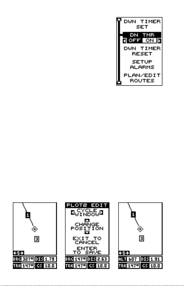
the desired number shows. Continue until the time
shown in the display is correct, then press the
ENT key .
T o start the timer, press the MENU k ey , then mov e
the black bo x to the “Dn Tmr Off On” label. Press
the right arrow key to start the timer. The timer
continues counting until you stop it. If you turn
the up timer’s alarm on (press the right arrow ke y
when the black box is on the (Up ALM...Off/On
label), it will flash a message when it reaches the
time you entered in the up timer set menu. Press
the EXIT key to erase the message .
You can reset either alarm to the time you originally set by pressing the
MENU key, then moving the black box to either the “Up Tmr Reset” or
“DN Tmr Reset” label, then press the right arrow key.
REPROGRAM BO XES
The digital boxes on the PLOT-2 and both NAV screens can be reprogrammed. The changes you make to the screen will remain in memory,
even if all po wer is remov ed from the unit. You can, how ev er , return to the
factory settings from the “Preset Groups” item in the “System Setup” men u.
To customize a screen, first switch to the screen that you want to customize. In this e xample, we’ll change Plot-2. Next, press the MENU key, then
highlight the “Reprgr Bo xes” menu. Press the right arrow ke y . The screen
shown below center appears.
This is the plot-2 edit screen. The “BRG” box near the left corner flashes,
21
Page 26
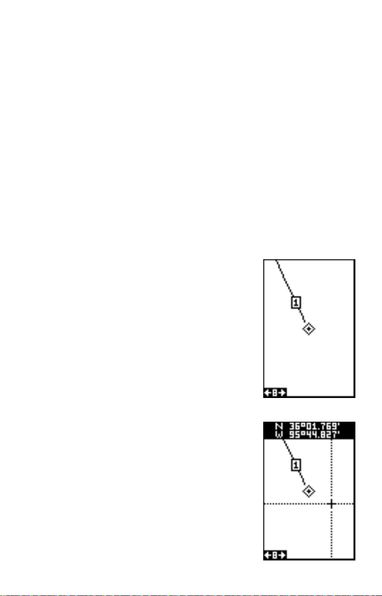
which means it’s ready for change. If you don’t want to change this box,
simply press the up or down arrow key to move to the box that you do
want to change. In this example, we will change the BRG box to altitude
(ALT). To do this, simply press the left or right arrow key while the box is
flashing. The bo x changes each time the arrow k ey is pressed. When the
desired box appears, then you can change another box or save your
changes by pressing the ENT key. If you want to leave this screen without saving the changes, simply press the EXIT key. In this example, we
simply changed the BRG to ALT, then pressed the ENT key. The screen
on the right on the previous page is the final version. Use this same
method to change the NAV screens.
WAYPOINTS
The GlobalNav 200 gives you the capability of creating your own database of locations, called “wa ypoints”. Y ou can sa ve y our present position,
cursor position, or enter a latitude/longitude and save it as a waypoint.
The GlobalNav 200 can store up to 999 wa ypoints.
Saving Your Present Position as a Waypoint
(Quick Save Method)
To save your present position, simply press the
WPT key
twice
. The GlobalNav 200 puts y our current position into the first available w aypoint number on the list. A message appears on the displa y
telling you the waypoint number it just used. This
also momentarily places you in the database
menu. Anytime a database menu is showing, simply press the WPT k ey once and the unit will store
your present position in the waypoint list.
Every time you sav e a waypoint, the date and time
are logged along with the position data. It’s position is also placed on the plotter as shown abov e.
In this case, waypoint number one w as assigned
when we quick-saved our position.
Saving The Cursor Position as a Waypoint
When the cursor is showing on the plotter and
you press the WPT k ey twice , the GlobalNa v 200
puts the
cursor’s
position into the first available
waypoint number. In the example screen shown
at right, the cursor is placed at the desired location. Pressing the WPT twice causes waypoint
number two to be placed at the cursor’ s crosshairs.
22
Page 27
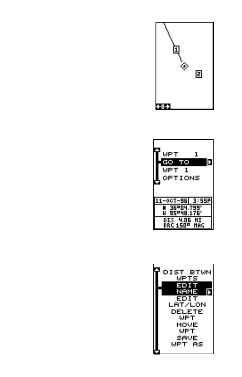
(See the screen at the top of the next page.) A
message appears on the display telling you the
waypoint number it just used. Wait a f ew seconds
and the menu will clear automatically. Press the
EXIT key to erase the cursor.
Saving Y our Present P osition as a Waypoint
(Select Number Method)
The method shown above doesn’t let y ou choose
the waypoint number. You can pick the waypoint
number, then save your present position. To do
this, first press the WPT k ey once. A screen similar to the one at right appears.
Now press the up arrow ke y once. This is the wa ypoint number selection menu. Press the left or
right arrow keys until the waypoint number appears that you wish to store your present position. In this e xample , w e’re going to store a position as waypoint number
6.
Now press the down arrow key until the “WPT
Options” label is highlighted. Press the right arrow key. A screen similar to the one shown at right
appears.
Highlight the “SaveWPT As” label (shown at the
bottom of the menu) and press the right arrow
key when y ou’ re at the location you wish to sav e.
This saves your present position under the waypoint number you selected on the first page.
Saving Cursor P osition as a Waypoint
23
Page 28
(Select Number Method)
To save the cursor position under a specific waypoint number, first position the cursor at the desired position. Then follow the previous instructions for saving y our present position as a waypoint using the select number method. Remember, the
method
of saving your present position and
the cursor’s position is identical.
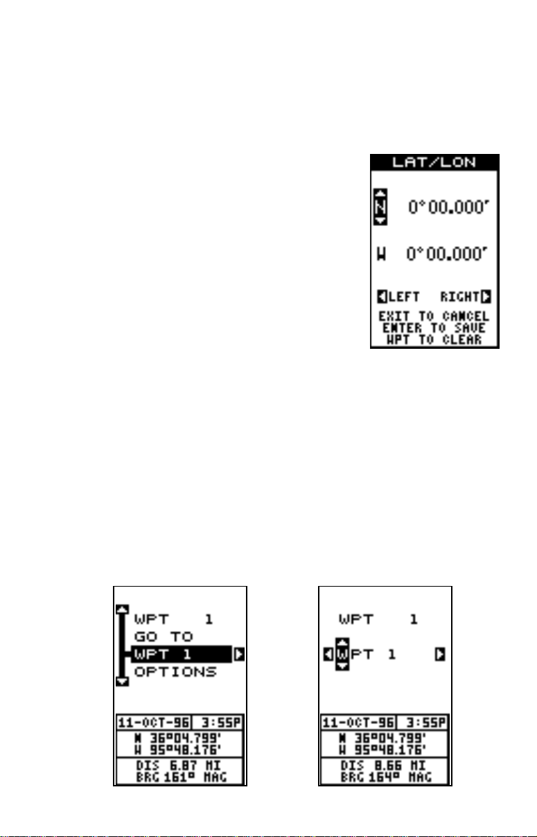
Edit Lat/Lon
The GlobalNav 200 lets you enter any latitude/
longitude using the keyboard and save it under
any wa ypoint number , from 1 to 750. You can also
change any waypoint’ s position using this method.
To do this, first select the waypoint number that
you want to save a position under from the waypoint menu. In this example, we’ll use waypoint
number 10. Next, highlight the “Options” menu and
press the right arrow key. Now highlight the “Edit
Lat/Lon” menu and press the right arrow k ey. The
screen shown at right appears. Using the left and
right arrow keys, highlight each n umber in the position and change it using the up and down arrow ke ys. When you’re ready to sa ve this position
and return to the waypoint screen, press the ENT key. The location you
entered shows at the bottom of the screen under the waypoint number
you selected. Note: You can also use this method to change the position
of an existing wa ypoint.
WAYPOINT NAMES
The GlobalNav 200 automatically assigns the waypoint number as a name
when the waypoint position is sa ved. You can find a wa ypoint by highlighting the name on the waypoint menu as sho wn below left. No w press the
right arrow key. The screen shown below right appears. Use the arrow
24
Page 29
keys to scroll through the sa ved waypoints. Only
waypoints that hav e a position will show using this
method.
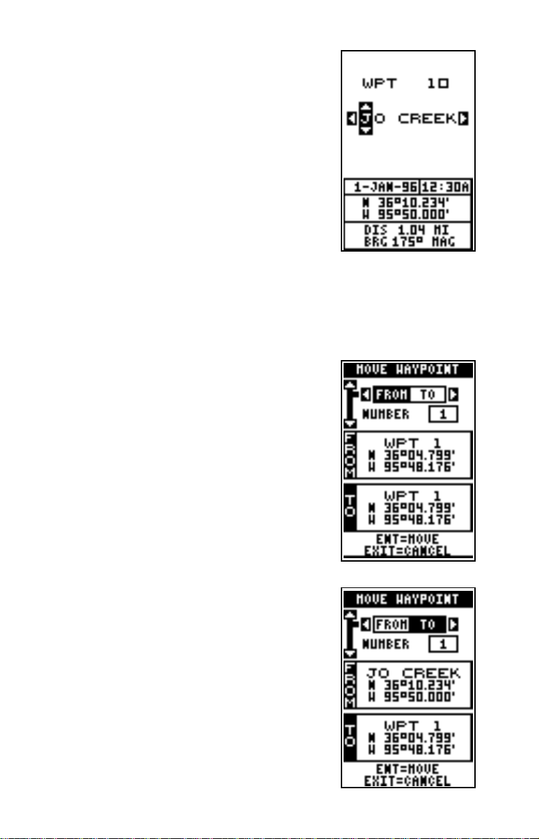
Edit Name
The GlobalNav 200 also lets you assign a name
to each waypoint. The name can hav e up to eight
characters. To name a waypoint, first select the
waypoint number that you wish to name . No w highlight the “WPT Options” label and press the right
arrow key. Finally, highlight the “EDIT NAME” label and press the right arrow key. A screen similar to the one at right appears.
Press the up or down arrow keys to select the first letter in the name.
Press the right arrow key to mo ve the blac k box to the ne xt position in the
name. Repeat this sequence until you’ve entered all of the letters in the
waypoint name. Press the ENT key to accept this name, the WPT ke y to
erase all characters in the name, or the EXIT k ey
to leave this screen without sa ving any changes .
MOVE A WAYPOINT
You can move all information from one waypoint
number to another. In this example, we’ll move
all of the information in waypoint number 10 to
waypoint number 20. T o do this , highlight the waypoint options label on the waypoint screen and
press the right arrow key . Now highlight the “Move
WPT” label. Press the right arrow ke y . The screen
shown at right appears. The black box is resting
on the “From” label. Now press the down arrow
key once to highlight the “Number” label. Press
the left or right arrow key until the number 10
appears. Now highlight the “T O” label, as sho wn
below. Highlight the “Number” label, then press
the right arrow key until the desired wa ypoint number shows in the box. When everything on this
page is correct, press the ENT key.
Note:The names in the “F rom” and “T o” box es are
not the waypoint numbers - the y are the waypoint
names. When a wa ypoint is moved from one number to another, the ne w waypoint number gets the
old waypoint name. For e xample, moving wa ypoint
number 2 to waypoint n umber 5 deposits the name
25
Page 30
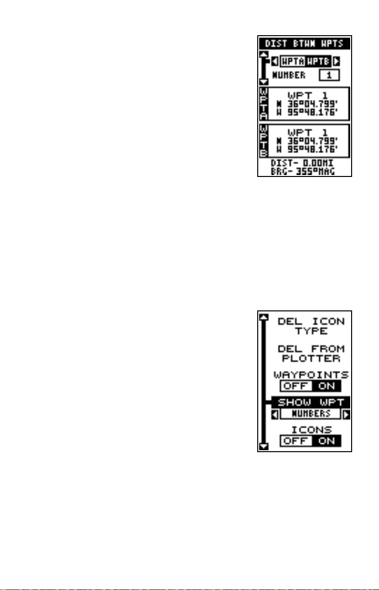
“WPT 2” in wa ypoint 5’s name field.
DIST ANCE BETWEEN WAYPOINTS
The GlobalNav 200 can easily give you the distance between two user wa ypoints. To do this, first
press the WPT ke y, highlight the “Options” men u
and press the right arrow key, then highlight the
“Dist Btwn WPTS” label and press the right arrow
key. The screen at right appears.
The black box is resting on the “WPT B” label.
Now press the down arrow key to highlight the
waypoint number label. Press the left or right arrow keys until the desired w a ypoint appears in the “WPT B” bo x.
Once you hav e the first waypoint showing on the screen, then y ou need
to choose the other waypoint that y ou’re going to measure. Move the black
box back to the “Select” label at the top of the screen, then press the left
arrow key to select “A”. Now choose the waypoint that you wish to measure. The distance and bearing from the first waypoint “A” to the second
waypoint “B” shows at the bottom of the screen. You can select more
waypoints to measure at this time or press the EXIT key to erase this
screen.
WAYPOINT OPTIONS
You can customize the look of the waypoints on
the plotter, or even turn them off. To do this, first
press the MENU key, then highlight the “WPT/
Icon Opts” label. Press the r ight arrow key. The
screen shown at right appears.
To keep the waypoints from showing on the plotter, simply press the right arrow key when the
“Wa ypoints” label is highlighted.
T o change the method wa ypoints show on the plotter, highlight the “SHO W WPT” label. The def ault
is numbers. In other words, when the waypoint shows on the plotter, it’s
number appears in a box, showing both its identity and location. You can
change this from number to name, or simply an empty box (position) sho wing no identifiable name or number b y pressing the left or right arrow keys
until the desired method appears. Now press the EXIT key. This erases
the menu and returns to the plotter with your selection.
26
Page 31
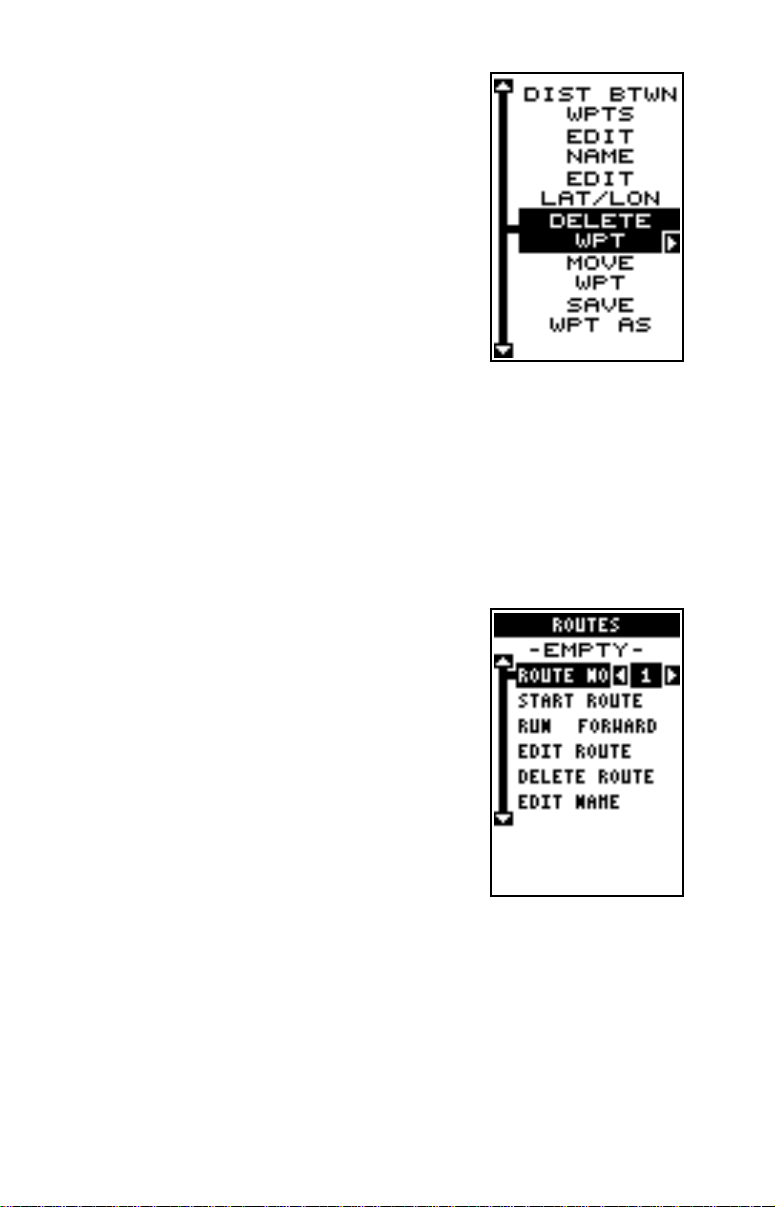
Delete a W a ypoint
To erase all of the information in a waypoint, first
press the WPT ke y, then select the waypoint you
want to erase. Now highlight the “Options” label
and press the right arrow key. Finally, highlight
the “Delete WPT” label and press the right arrow
key . A message appears, asking if you really want
to delete this waypoint. Press the right arrow k ey
to delete it, the left to exit without deleting the wa ypoint.
ROUTES
You can connect several user waypoints together to form a route. When
you recall the route, the GlobalNav 200 will sho w you navigation inf ormation to the first waypoint in the route, then when y ou reach that wa ypoint,
it switches to the next waypoint, and so on until you reach the last way point in the route.
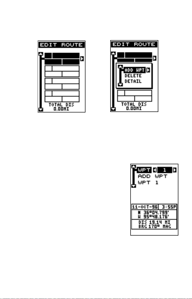
T o create a route , first press the MENU key, highlight the “PLAN/EDIT ROUTES” label, and press
the right arrow key. The screen shown at right appears.
This unit can store up to 99 different routes. Route
number one shows on this page. If you wish to
create a route using a different number, simply
press the left or right arrow keys until the desired
route number appears. In this example , howev er ,
we’ll use route number one.
At the bottom of this menu is the “Edit Name” label. If y ou wish to name the route, highlight that label, then press the right
arrow key. Use the arro w keys to name the route , (you can use up to eight
characters in the name) then press the ENT key when y ou’re finished.
To add waypoints to the route, highlight the “Edit Route” label and press
the right arrow key . The screen shown at the top of the next page appears .
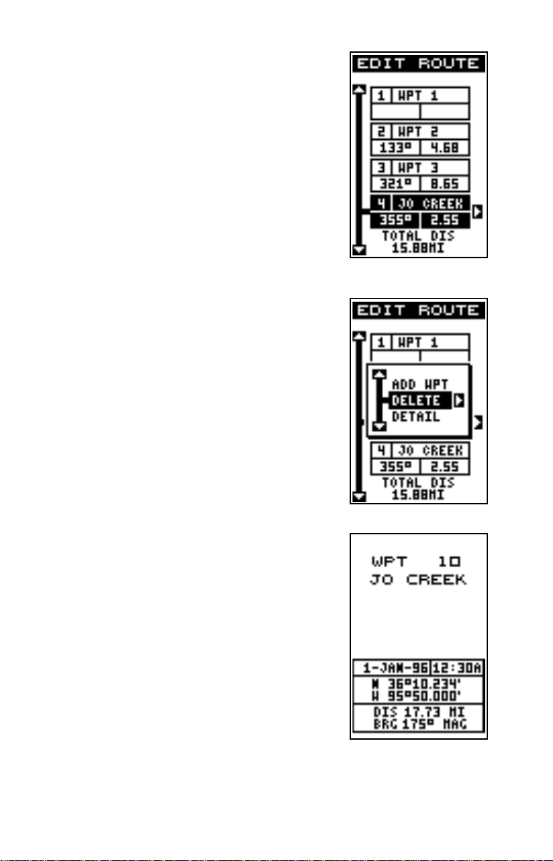
This is the waypoint list screen. This shows all of the wa ypoints that f orm
27
Page 32
the route. To select the first waypoint in the route, press the right arrow
key. A new menu appears as sho wn belo w right.
This menu lets you go to the wa ypoint selection menu, delete a wa ypoint
from the route, or see details about any waypoint in the route. Since we
want to add a waypoint to the route, press the right arrow key on the
“Insert From WPTS” label. The screen shown below appears.
Select Waypoints
Select the first waypoint either b y using the waypoint number at the top of the screen or waypoint
name menus. As you move through the list of
saved w a ypoints , their date and time sav ed, position, and distance and bearing from your present
position show at the bottom of the screen. When
the desired waypoint appears that you want to
use as the first waypoint on the route, move the
black box to the “Add WPT” label, then press the
right arrow key. The unit returns to the route planning screen with this waypoint placed in the first
location on the list.
To add more waypoints to the route, simply press the down arrow k ey to
the next position on the list and press the right arrow ke y . Continue until all
of the waypoints ha ve been added to the route .
28
Page 33
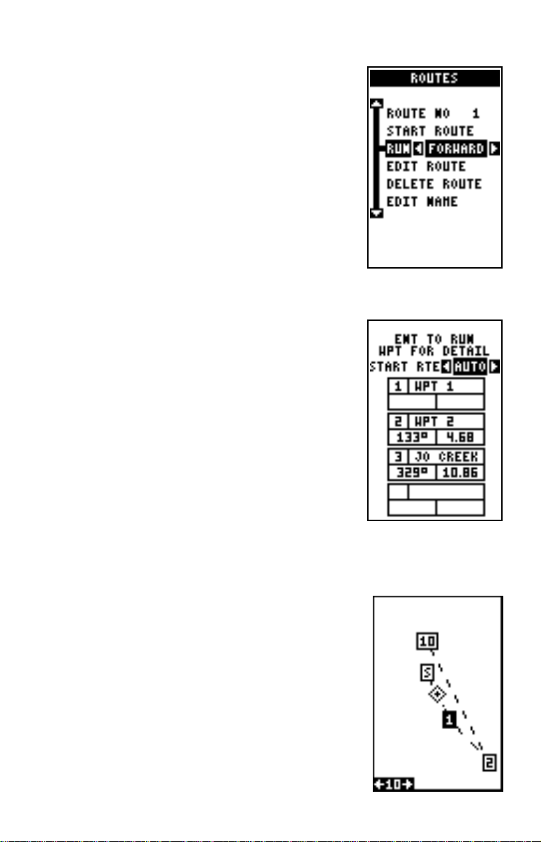
As you add wa ypoints to the list, their bearing and
distance from each other is shown to the right of
the waypoint name. On the screen at right, waypoint 2 is on a bearing of 133° and 4.68 miles
from waypoint 1. The total route distance is shown
at the bottom of this screen.
Finishing the Route
When you’ve selected all of the wa ypoints for the
route, simply press the EXIT key until you return
to the navigation, plotter , or windows screen. Your
route is saved in memory.
Delete a Waypoint
To delete a waypoint from a route, first select the
route, then highlight the EDIT ROUTE label and
press the right arrow key. Now highlight the w a ypoint that you want to remove from the route’s
list. Press the right arro w key. The screen show n
at right appears. Highlight the “Delete” label on
this menu and press the right arrow key. The unit
returns to the route list with the waypoint remov ed
from the list. (Note: This doesn’t delete the waypoint from the database, it only removes it from
the route.)
Waypoint Detail
T o vie w the position, bearing, distance, and other
information about a waypoint saved in a route,
first select the route, then highlight the desired
waypoint from the route’ s list. Now press the right
arrow key. The screen shown above appears.
Move the blac k box to the “Detail” label and press
the right arrow key. The screen at right appears.
This screen shows the waypoint’ s name, n umber
creation time and date, icon, position, distance,
and bearing from your present position. When
you’ re finished viewing this information, press the
EXIT key to erase it.
29
Page 34
Following a Route
Before starting the route, you’ll need to decide if
you want to start at the beginning and travel forward or start at the last waypoint in the route and
travel backwards (reverse) to the first waypoint.
The default is forward. To change it, press the
MENU key, then select the “PLAN/EDIT
ROUTES” label and press the right arrow key.
The screen shown at right appears.To run a route
from the end to the beginning, highlight the “RUN”
label, then press the right arrow key to change it.
To follow a route, first select the route number
that you wish to follow b y highlighting the “Route
No” label, and pressing the left or right arrow keys until the desired route
number appears. In this example we’ re using route
number one. Now highlight the “STA R T ROUTE”
label and press the right arrow key. The screen
shown at right appears.
The black box is on the “Start RTE Auto” label.
This starts the navigation to the waypoint that is
closest to your present position. If you want to
start the route with the first waypoint in the route,
press the right arrow key until the number “1” appears.
If you want to see details about the highlighted
waypoint, press the WPT key.
When you hav e e verything on this screen set as desired, press the ENT
key to start the GlobalNav 200 navigating to the
first waypoint on the route .
As you trav el to the first waypoint, the unit shows
navigation data to the waypoint. If you use the
plotter, as sho wn at right, the unit dra ws a dotted
line from your starting position (shown by the “S”),
and a dashed line from the first waypoint to each
of the other waypoints in the route. When you enter the radius set by the arrival alarm, the
GlobalNav 200 automatically switches to the ne xt
waypoint on the list, showing navigation data to
that waypoint, and so on until the last wa ypoint on
30
Page 35
the route list has been reached. (Note: The arrival alarm does not hav e to
be turned on in order to use the route feature.)
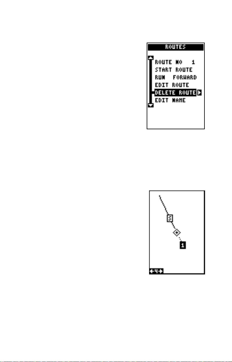
Delete a Route
To erase a route, first press the MENU key, then
highlight the “Plan/Edit Routes” label and press
the right arrow key. The screen shown at r ight
appears. Now select the route y ou want to erase
at the top of the screen, then highlight the “Delete Route” label and press the right arrow k ey. A
message appears, asking if you really want to
erase the route. If you press the right arrow key,
the route will be erased.
NA VIGATION
Navigate T o a Waypoint
The GlobalNav 200 makes it easy to navigate to an y waypoint. First, press
the WPT key, then select the desired waypoint by first highlighting the
waypoint number at the top of the screen, then
pressing the left or right arrow keys until the desired waypoint n umber appears. No w highlight the
“Go To ” label and press the right arrow key. The
unit immediately returns to the navigation, plotter,
or windows screen and shows navigation information to the selected location.
In this example, we recalled waypoint number 1.
Switching to a plotter screen (shown at right)
shows our starting location “S”, the recalled waypoint “1”, and our present position.
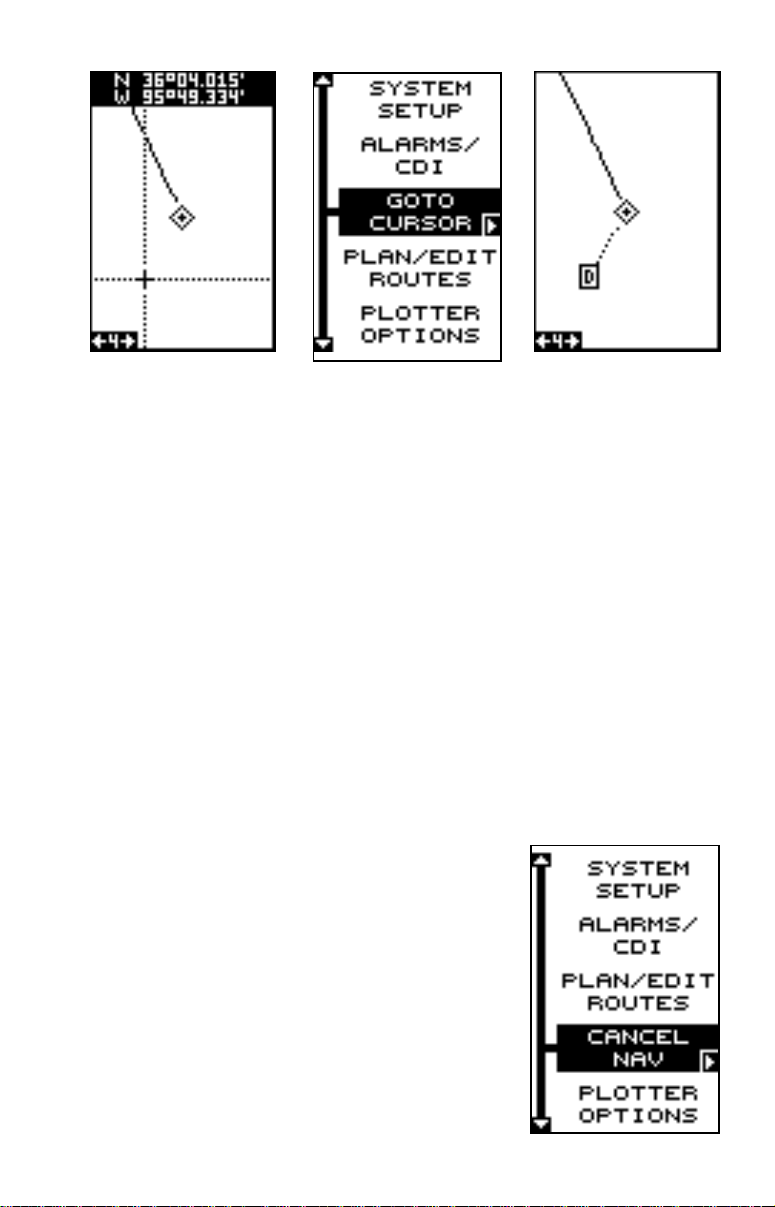
Navigating to a cursor location
The GlobalNav 200 lets you navigation to a location without storing it in
the waypoint database by using the plotter and cursor. To do this, first
switch to the plotter screen. Now mo ve the cursor to the location that y ou
want to navigate to. Next, press the MENU key. A ne w men u appears on
the list: “Go To Cursor”. Press the right arrow key. The GlobalNav 200
shows nav data to the cursor location (shown as “D” on the plotter). See
the screens at the top of the next page.
31
Page 36
Navigating to a Waypoint using the Plotter
The unique “birds-ey e” vie w used by the plotter giv es you an easy w a y to
navigate to a waypoint. On the plotter screen shown on the previous
page, the diamond with a cross in it is your present position. The bo x with
the “S” in it was your starting location when you recalled the waypoint.
The dotted line is called a track line and is the shortest path from the
starting location to the destination. The number “1” is waypoint number
one, which is the recalled waypoint and the destination. The “D” on the
plotter screen at the top of this page is the cursor destination, when the
cursor position is used as a destination. If y ou follow the track line, you’ll
reach the destination, covering the shortest distance in the least time.
CAUTION!
The GlobalNav 200 does NOT tak e land features, altitudes, restricted or
prohibited areas, or any other feature into account when it projects the
track line on the screen. Therefore, you must use care when navigating
on the track line and avoid any object that may be in your path to the
destination.
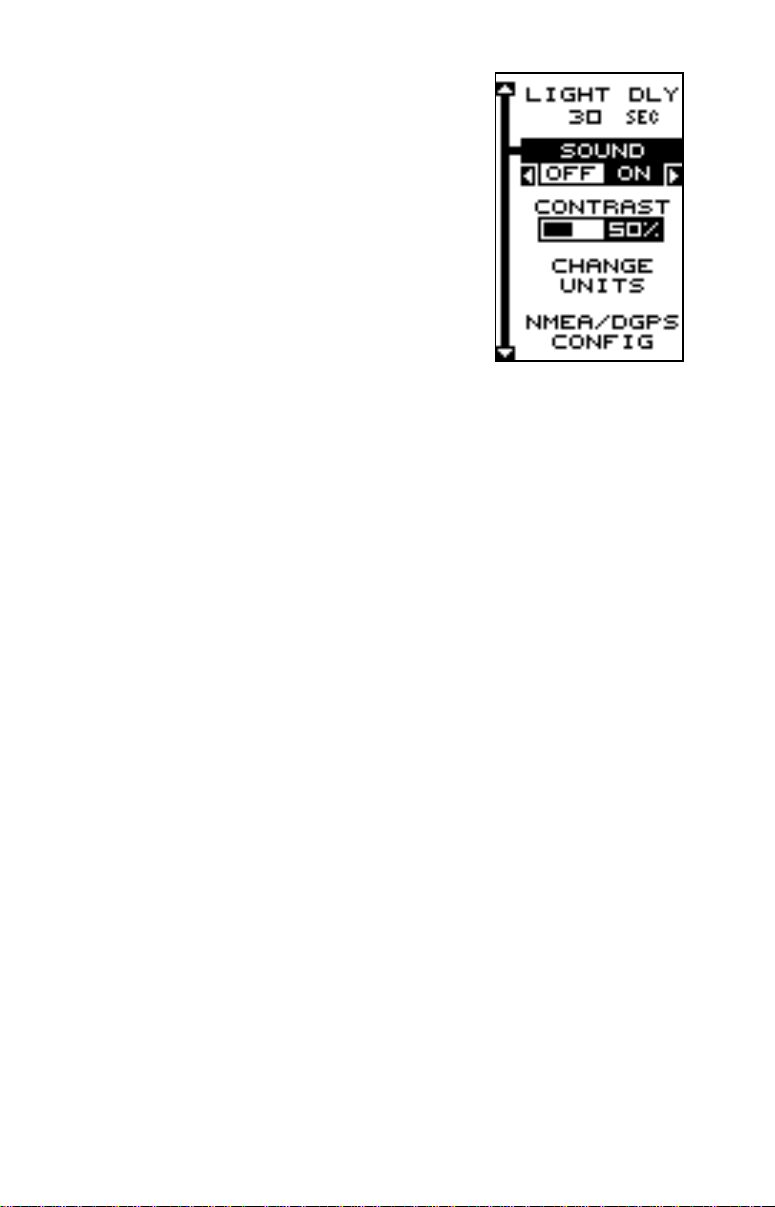
CANCEL NAVIGATION
The GlobalNav 200 continues to navigate to a recalled waypoint, the last waypoint in a route, or
the cursor position until you stop it.
To stop the navigation function, press the MENU
key, then press the up or down arrow keys until
the “Cancel Navigation” label is highlighted. Press
the right arrow key. The unit stops showing navigation information.
32
Page 37
SYSTEM SETUP
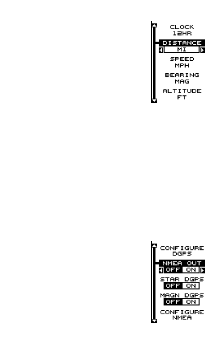
The GlobalNav 200 has sev eral menus and commands listed under the “System Setup” label on
the main menu. These commands affect the basic operation of the unit. To use them, press the
MENU key, then highlight the “System Setup” label. Press the right arrow k ey. The screen shown
at right appears.
BA CKLIGHT
The GlobalNav 200’s display has lights that can
be turned on for night use. To turn the lights on,
simply press the PWR key. T o turn them off , press
the PWR key again. An indicator on the satellite status screen (Group
“O”) shows when the lights are on.
The GlobalNav 200 automatically turns the lights off after 30 seconds to
preserve the battery power. It will do this even if the external power is
applied to the unit.
The time delay is adjustable from 5 to 240 seconds . Y ou can also turn the
lights on continuously from this menu. Use the “Light Dly” (light delay)
menu to change this. Highlight this menu, then press the right arrow key
to increase the time the lights are on, the left arrow key to decrease it.
Press the EXIT key to erase this men u.
SOUND
To turn the speaker off, highlight the “SOUND” label as shown above,
then press the left arrow key. Note: This turns the speaker completely off .
The unit will not sound a tone when a key is pressed, nor will any alarm
sound. The alarm messages will still flash on the screen, howev er.
CONTRAST
To adjust the display’s contrast, highlight the “Contrast” label on the “System Setup” menu as sho wn abov e. Press the right or left arrow keys until
the screen’s contrast is best for the lighting conditions. Press the EXIT
key to erase this screen.
33
Page 38
Units of Measure
The GlobalNav 200 can show its data in many
different formats. For example, distance can be
displayed in statute miles (MI), nautical miles (NM),
or kilometers (KM). The f ollowing can be changed
on the “Change Units” menu: (Defaults shown in
bold)
Clock ...............12-hour (a.m.-p.m.), 24 hour
Distance .......... miles, nautical miles, kilometers
Speed ..............miles per hour, knots,
kilometers per hour
Bearing............ magnetic, true
Altitude ............ feet, meters
T o change a unit of measure , first select the “Change Units” label from the
“System Setup” menu. The screen shown above appears. Highlight the
desired selection, then press the left or right arrow key. You can change
any or all of the settings on this page. When you’re finished, press the
EXIT key.
NMEA / DGPS
The GlobalNav 200 transmits data through the data port in the back of the
unit using NMEA 0183 format, version 1.5 or 2.0. This data is used by
other electronic devices such as marine autopilots for position and steering information.
DGPS on the other hand, is a data input. DGPS is an acronym f or Diff erential Global Positioning System. Currently, it relies on a system of groundbased transmitters that send correction signals to small DGPS receivers.
DGPS gives you more accurate positions than is
otherwise possible.
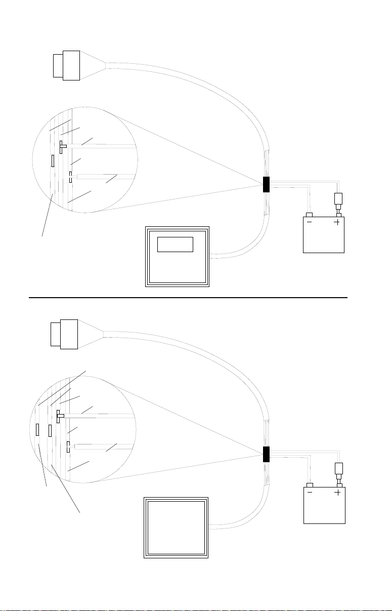
All wiring connections to the GlobalNav 200 are
made to it’s power cable. See the sample wiring
diagrams on the next page f or general wiring procedures. Read your other product’s owner’s
manual for more wiring information.
Once the cables are wired, turn the GlobalNav
200 on, press the menu key, and select NMEA /
DGPS from the System Setup menu. A screen
similar to the one at right appears.
34
Page 39
TO GLOBALNAV 200
GLOBALNAV 200’S
WIRES
WHITE WIRE
RED WIRE
TO +12V
BLACK WIRE
GROUND WIRES
OTHER DEVICE’S
WIRES
OTHER
DEVICE’S
RECEIVE
DA TA WIRE
OTHER
DEVICE
GLOBALNA V 200
TRANSMITTING NMEA
DA TA TO ANOTHER DEVICE
12 VDC
BATTER Y
TO GLOBALNAV 200
GLOBALNAV 200’S
WIRES
DGPS
RECEIVER’S
TRANSMIT
DATA WIRE
GREEN WIRE
WHITE WIRE
RED WIRE
BLACK WIRE
GROUND WIRES
DGPS
RECEIVER’S
RECEIVE
DA TA WIRE
(IF NEEDED)
TO +12V
DGPS
RECEIVER
35
GLOBALNA V 200
RECEIVING DATA
A DGPS RECEIVER
FROM
12 VDC
BATTER Y
Page 40
NMEA OUTPUT
T o turn the NMEA output on, highlight the “NMEA OUTPUT” menu (shown
at the bottom of the previous page), then press the right arrow ke y . If y our
other equipment works, then no setup will need to be performed. If your
other equipment doesn’t recognize the NMEA data being sent by the
GlobalNav 200 and the wiring is correct, then you may need to change
the NMEA or the serial communication settings.
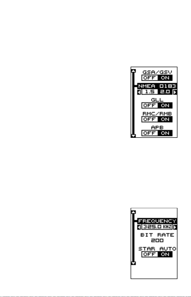
Configure NMEA Output
Highlight the “Configure NMEA Output” menu,
then press the right arrow key. A screen similar to
the one at right appears.
NMEA 0183 Version
There are two versions of the NMEA data, 1.5
and 2.0. If y our other equipment requires 2.0, press
the right arrow key to select it.
GLL, RMC/RMB, APB, GGA, GSA/GSV
Sentences
Some equipment requires different sentence. The
GlobalNav 200’s default setting for these sentences is on. In other words, it automatically sends these sentences when
NMEA is turned on. To turn any of these off, move the black box to the
desired menu and press the left arrow key. Press the EXIT key when
everything on this screen is the wa y you want it.
DGPS
The GlobalNav 200 will recognize Starlink® and Magnavox® automatic
DGPS receivers. If you have either one of these receivers, simply highlight the “Star DGPS” or “Magn DGPS” on the NMEA / DGPS menu and
press the right arrow key to turn it on. (Note: If y ou
have a Magna vo x DGPS receiver connected, the
GlobalNav 200 can’t send NMEA data.) With the
exception of serial communications, typically no
other setup needs to be made with these receivers.
If you hav e an y other Magna v o x or Starlink compatible DGPS receiver connected to the GlobalNa v
200, you may need to change the settings . To do
this, move the b lack bo x to the “Configure DGPS”
label and press the right arrow key. A screen similar to the one at right appears.
36
Page 41
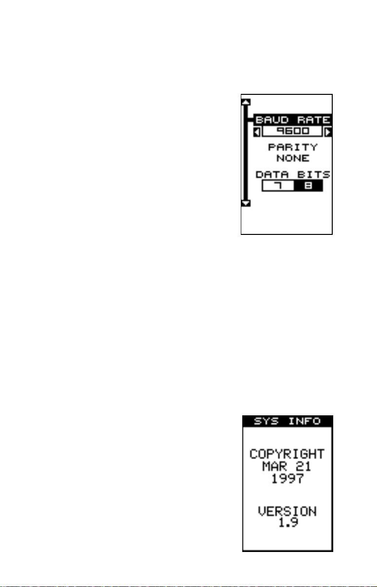
These menus select the beacon receiver’ s frequency and bit r ate (in bits
per second). T o change one of these settings , simply highlight the menu
item you wish to change, then press the right or left arrow key until the
desired number appears. Press the EXIT k e y when y ou’re finished.
SERIAL COMMUNICA TIONS SETUP
To set the data por t, move the black box to the
“Com Port Setup” on the System Setup menu.
Press the right arrow key. The screen shown at
right appears.
Check your DGPS receiver’ s manual for the proper
data settings. Highlight the menu item you need
to change. Press the left or right arrow keys to
change them. The serial port defaults are 4800
baud, no parity, and 8 data bits. Press the EXIT
key to erase this men u.
RESET OPTIONS
To return the GlobalNav 200 to its original factory settings, highlight the
“Preset Options” menu on the System Setup screen. No w press the right
arrow key. A message appears , asking if you w ant to restore the original
options. Press the right arrow k e y if you do, the left arrow k ey to quit.
If you restore the unit to the factory settings, all options such as contrast,
alarms, and other system choices are returned to their default values.
Howe ver, no waypoints, routes, or icons are erased.
RESET GROUPS
To return all groups on the navigation and plot-2 screens to their factory
defaults, highlight the “RESET GROUPS” label on the “System Setup”
menu. Finally, press the right arrow key. All digital
boxes on these screens are reset to their factory
settings.
SYSTEM INFO
The system information screen shows the release
date and the version number of the code stored
inside the GlobalNav 200. To view this screen,
highlight the “System Info” label on the “System
Setup” menu. Now press the right arrow key. A
screen similar to the one at right appears. Press
the EXIT key when you’re finished reading this
screen.
37
Page 42
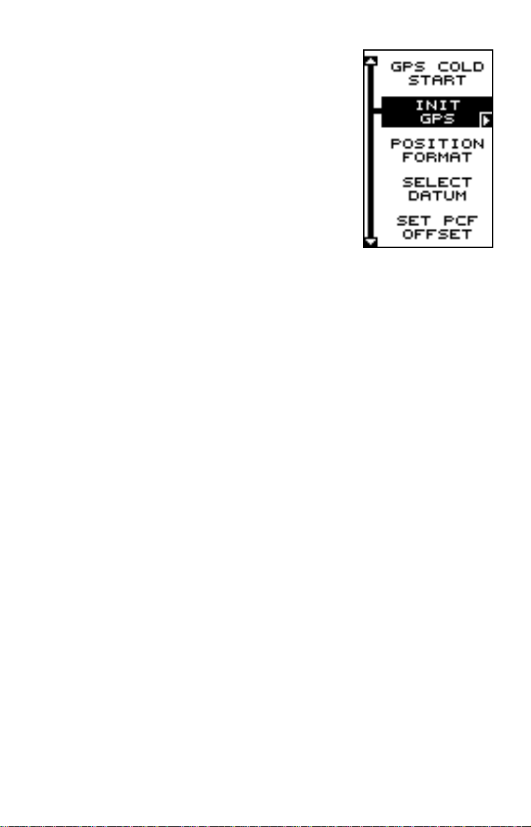
GPS SETUP
The GPS Setup menu has sub-menus that affect
the GPS receiver . From these men us you can set
the update rate, initialize the GPS receiver, do a
self-test on the receiver , and do a cold-start. (Note:
The “Initialize GPS receiver” is covered in the
“Finding Your Position” section in the front of this
manual.
To view these menu items, press the MENU key,
then highlight the “GPS Setup” menu. Press the
right arrow key. The screen at right appears.
GPS Cold Start
When the GlobalNav 200 is turned on for the first time “out of the bo x”, it
automatically sends a “cold-start” message to the GPS receiver . You can
also send a cold start message to the receiver at any time.
If the unit can’t lock on to the satellites using the data you’v e given it, or if
it has trouble finding the satellites, perhaps it is using the wrong data. This
can happen if you’ve entered the wrong data by accident when initializing
the receiver. For example, if you entered east longitude instead of west.
Or if you’ve mov ed a long distance with the unit turned off.
To send a cold star t message to the receiver, highlight the “GPS Cold
Start” label, then press the right arrow key. A message appears, asking
you if you really want to do a cold start. Follow the instructions on this
message page.
The unit will begin searching for the satellites. It can take as long as 5
minutes for it to lock on to the necessary satellites. Remember, when it
does, your local time and possibly date can be wrong. Use the method
shown in the initialization section at the front of this manual to change
them, if needed. Once this is done, an internal clock will k eep the correct
time, ev en when the unit is turned off. The GPS system updates this cloc k
when the unit is locked on to the satellites.
38
Page 43
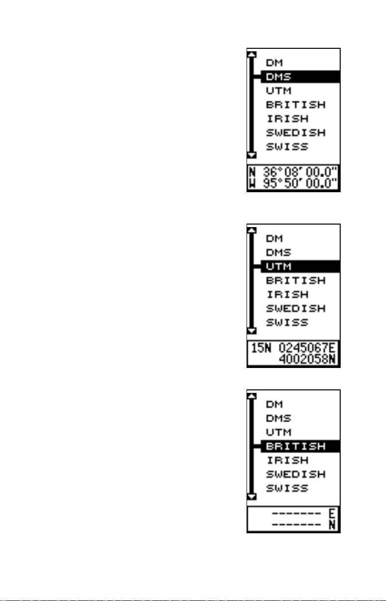
Position Format
To change the position format, highlight the “Position Format” label on the “GPS Setup” menu
(shown on the previous page), then press the right
arrow key. A screen similar to the one at right appears.
The GlobalNav 200 can show the position in degrees, minutes, and thousandths of a minute (36°
28.700') or degrees, minutes, seconds , and tenths
of a second (36° 28' 40.9"). It can also sho w position in UTM (Universal Transverse Mercator) projection, British, Irish, Swedish, Swiss, Finnish, and
Military Grid systems.
UTM’s are marked on USGS topog raphic charts.
This system divides the Earth into 60 zones, each
6 degrees wide in longitude. Their unit of measure is in meters. For example, 15N means that
the position shown to the right of the “15N” is in
zone 15, and it’ s north of the equator.
British, Irish, Swedish, Swiss, and Finnish grid systems are the national coordinate system used only
in their respective countries.
Note: In order to use either the British, Irish, Swedish, Swiss, or Finnish grid systems, you m ust be
in the respective country.
The GlobalNav 200 will pick the matching datum
for you when y ou select the grid. See the Datums
section for more information.
39
Page 44
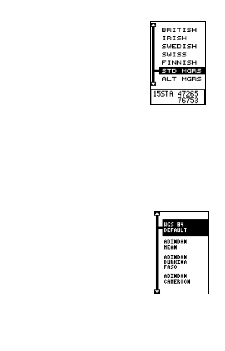
The GlobalNav 200 can use the military grid reference system (MGRS). It uses two grid lettering schemes, which are referred to as standard
and alternate MGRS on the GlobalNav 200. Y our
position and datum in use determines which one
to use. If you use the standard, and your position is off significantly, then tr y using the alternate.
Press the up or down arrow ke ys to highlight the
desired position format. Press the EXIT key to
both select the format and erase the position format menu.
DATUM
Maps and charts are based on a survey of the area that’s cov ered b y the
map or chart. These surve ys are called “Datums”. Maps that are created
using different datums will show the same latitude/longitude in slightly
different locations.
All datums are named. The GPS system is based on the WGS-84 datum,
which covers the entire world. Other datums may also cover the entire
world, or just a small portion. By default, the GlobalNav 200 shows your
position on the map using the WGS-84 datum. How ev er, it can sho w your
position using one of 191 different datums.
To change the datum, first press the MENU key,
then highlight the “GPS Setup” label and press
the right arrow key. Now highlight the “Select Datum” label. Finally , press the right arrow k ey again.
A screen similar to the one at right appears.
The WGS-84 label is highlighted. T o change it, simply press the up or down arrow keys to highlight
the desired datum, then press the ENT key. This
selects the datum and erases the select datum
menu. To erase the menu without changing the
datum, simply press the EXIT key.
A list of the datums used by the GlobalNav 200 is in the back of this
manual.
40
Page 45
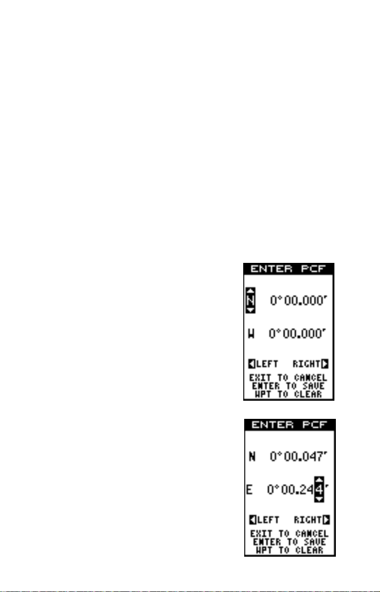
PCF (Position Correction Factor)
Another method used to make your displa y match a chart or map is called
“PCF” or Position Correction Factor. This unit gives you the capability to
move or offset the position shown on the display to match one on the
chart. The unit will add this offset to all position and navigation displays at
all times.
Remember, the position error on an y radio navigation system is v ery dynamic and the PCF offset should never be used in an attempt to cancel
the error.
In general terms, PCF should only be used if your map indicates what the
possible error is. PCF should always be reset to zero when you’re
finished with the chart.
For example, suppose you are stopped at a location that is accurately
marked on a chart. Your unit shows a longitude position that is .244 minutes east of the one on the chart and .047 minutes north latitude. Using
the PCF feature, you can make the GlobalNa v 200
match the chart you’re using. If you mov e, the unit
will continuously add the change to all position,
navigation, and mapping displays. This makes it
more closely match the datum used by the chart.
For this reason, you should be careful when entering the PCF offset. It’s saved in memory and
doesn’t change when the unit is turned off. Ho wever, resetting the unit does erase the PCF offset.
To change the PCF offset, first press the MENU
key , then highlight the “GPS Setup” label and press
the right arrow key. Now highlight the “Set PCF
Offset” label. Finally, press the right arrow key
again. A screen similar to the one abov e right appears.
Now enter the correction for y our location. Remember, this is the difference between the location
shown on the present position display and the position shown on the chart. In this example , we entered 0 degrees, 0.047 minutes north latitude and
0 degrees, 0.244 minutes east longitude. That is
the difference between the present position sho wn
by the GlobalNav 200 and the one on our chart.
41
Page 46
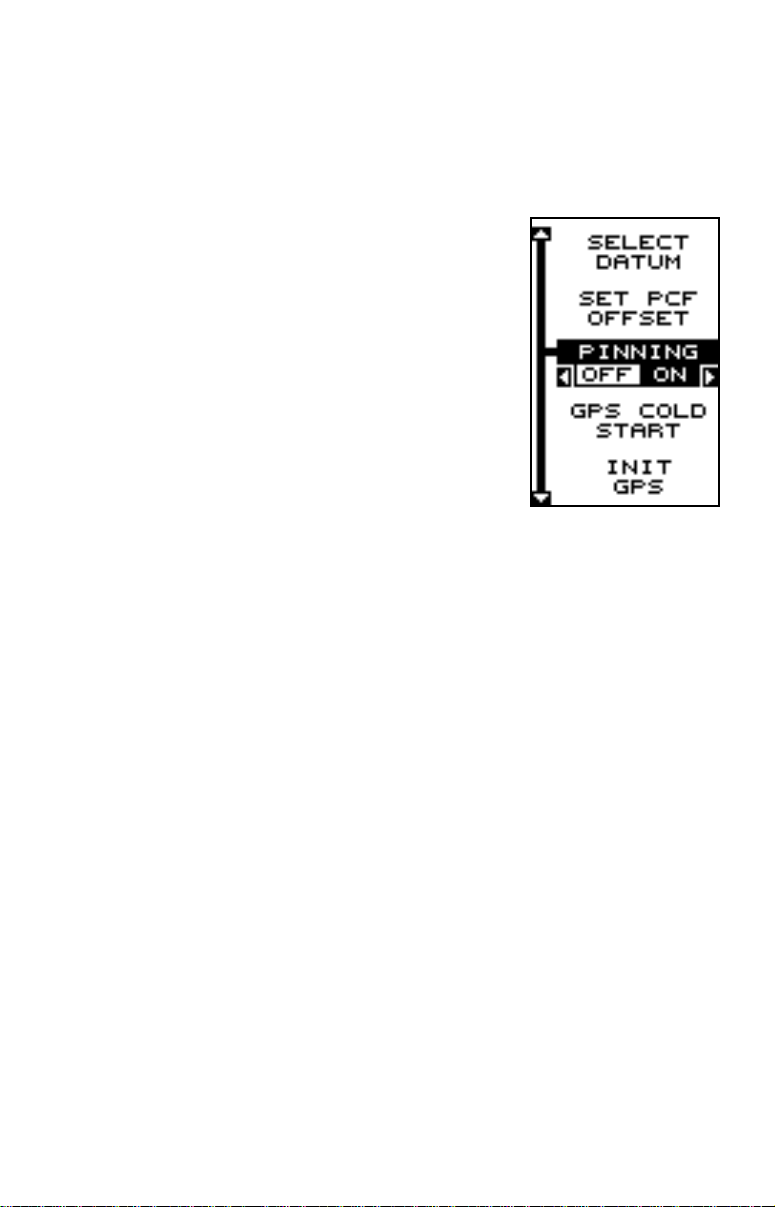
After you’ve entered the latitude/longitude correction, press the ENT ke y
to accept it. The GlobalNav 200 er ases the PCF entry screen and returns
to the navigation or mapping screens with the correction factor applied.
POSITION PINNING
When using a GPS receiver at extremely low
speeds, it can have trouble determining your
course over ground, or direction y ou’ re tra velling.
This is due in large part to SA, or selective availability. SA is small inaccuracies purposefully put
into the GPS satellite’s signal b y the government.
This cause wide variations in the track displa y and
other navigation displays when using the unit at
slow speeds.
If you’ re using the GlobalNav 200 without DGPS
and stop, the position pinning feature locks the
present position indicator on the plotter until you’ve
moved a short distance or exceed a very slow
speed. This prevents the “wandering” plot trail seen when you’re stopped
with position pinning turned off. This also affects the na vigational displays.
The easiest way to see the eff ects of S/A is to stand still with the GlobalNav
200 turned on and watch your plot trail with position pinning turned off.
You’ll see the present position change, speed increase and decrease,
and a random plot trail on the plotter’ s screen.
If you wish to turn the position pinning feature off, press the MENU key,
then highlight the “GPS Setup” label and press the right arrow key. Now
highlight the “Pinning” label. Finally, press the left arrow k ey.
ALARMS
The GlobalNav 200 has several alarms. You can set an arrival alarm to
flash a warning message when you cross a preset distance from a waypoint. For example, if you have the arrival alarm set to .1 mile, then the
alarm will flash a message when you come within .1 mile of the recalled
waypoint. The course deviation indicator alarm (CDI) can warns when
your track drifts too far to the right or left of the line to the waypoint. For
example, if the alarm is set to .1 mile, then the alarm flashes a message
if you drift .1 of a mile or more to the right or left of the line to the waypoint.
The anchor alarm is triggered when you drift outside of a preset radius.
Again, using the .1 mile as an example, if y ou’ re anchored and your boat
moves more than .1 of a mile , the alarm will flash a message.
To use any of these alarms, first press the MENU key, then select the
42
Page 47
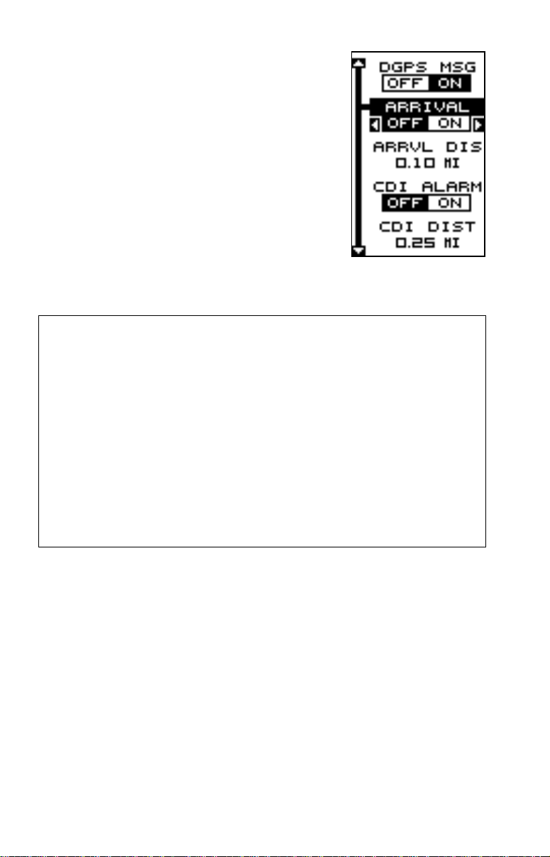
“ALARMS/CDI” menu. A screen similar to the one
shown at right appears. Press the up or down arrow ke y to move the black bo x to the desired alarm,
then press the right arrow key to turn it on.
T o adjust an alarm’ s distance, mov e the black bo x
to the alarm’s “DIST” menu item, then press the
right or left arrow keys to increase or decrease
the alarm’s distance.
When you’ re finished adjusting the alarms, press
the EXIT key to erase this men u.
Important Alarm Notes:
Anchor Alarm - Since civilian users don’t receive the accuracy given to
military users, the anchor alarm may be triggered even when you’re
sitting still. This typically happens when using small (less than .05 mile)
anchor alarm ranges. If y ou have a DGPS beacon receiver connected
to the GlobalNav 200, smaller ranges ma y be usable .
Arrival Alarm - If you set the arrival alarm’s distance to a small number ,
and you run a route (see the routes section), the GlobalNav 200 may
not show navigation data to the next waypoint, once you arrive at the
first one, since you may not be able to come close enough to the first
waypoint to trip the arrival alarm.
MESSAGES
The position and DGPS message selections are found on the Alarms/
CDI menu. When turned on, the position message appears for a f ew seconds whenever the GlobalNa v 200 loc ks onto the satellites and sho ws a
position. It also appears when the unit loses the lock onto the satellites
and cannot navigate. Pressing the EXIT key erases these messages.
The DGPS message appears whenever the unit begins or stops using
DGPS data to help determine your position.
The default setting f or these messages is “on”. T o turn either message off ,
select the “Setup Alarms” menu from the main men u, then move the blac k
box to the desired message and press the left arrow k ey. Press the EXIT
key to erase this screen.
43
Page 48
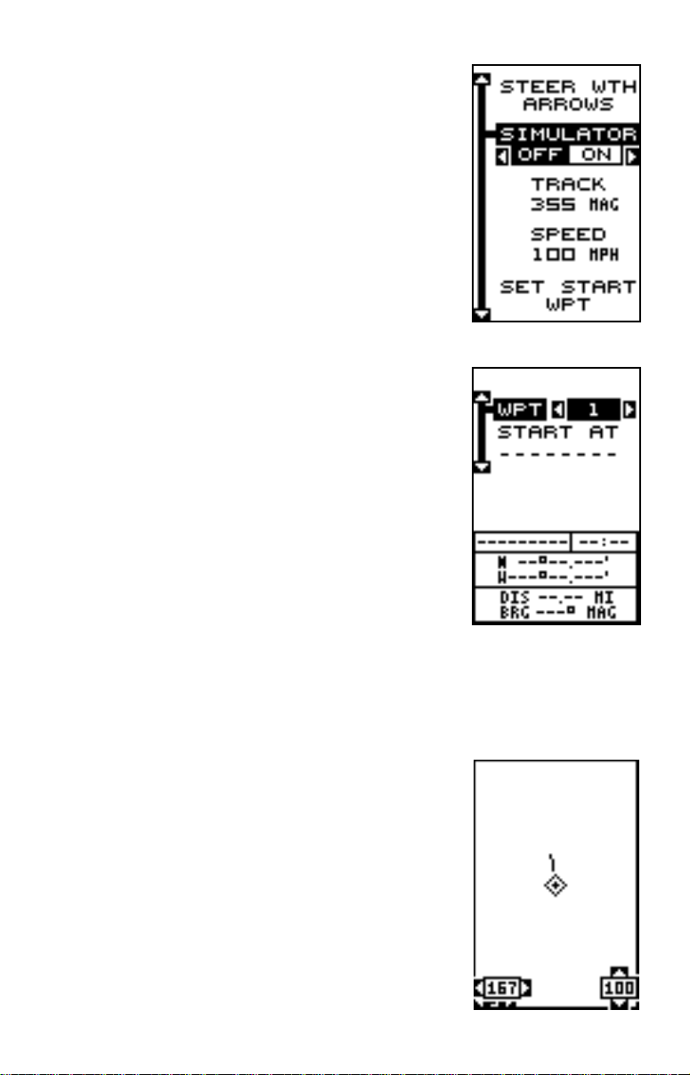
SIMULATOR
A simulator is built into the GlobalNav 200 that
has sever al options. Y ou can use nearly all of the
unit’s features - even save and recall waypoints.
This is useful for trip planning.
To use the simulator, press the MENU key, then
press the up or down arrow ke ys until the “Simulator Setup” menu is surrounded b y the black box.
Now press the right arrow key. The screen shown
at right appears.
If you simply press the right arrow key, turning the
simulator on, the GlobalNav 200 will start from
your present position and follo w a track of 355° at
100 miles per hour.
To change either the track or speed, highlight the
one you want to change, then press the right or
left arrow key. When the numbers are correct,
press the EXIT key.
Starting Position
Normally , the starting position for the simulator is
your present position. If you want to change the
starting position, highlight the “Set Starting Waypoint” label on the Simulator Setup menu, then
press the right arrow key. The screen shown at right appears.
You can select any waypoint as the simulator’s starting point. Select the
starting point by pressing the right arrow key on the “WPT#” label until the
desired starting waypoint number appears. Now
highlight the “Start At” label and press the right
arrow key . The GlobalNav 200 returns to the Simulator Setup menu using the waypoint you specified as the starting waypoint.
Use Arrow Ke ys to Steer
This option lets you change both the course and
speed on the screen as the simulator is running.
To do this, highlight the “Steer With Arrows” label
on the Simulator Setup screen, then press the right
arrow key . The screen shown at right appears. Use
the up and down arrow keys to increase or de-
44
Page 49

crease the speed. Use the right and left arrow keys to change the track.
Press the EXIT key to erase these men us .
When you’re finished changing the track and speed, press the EXIT key
to erase the menus.
T o turn the simulator off , press the MENU key, then move the blac k box to
the “Simulator Setup” label. Finally, press the left arro w ke y.
Note: Your plot trail will be erased when you turn the simulator on or off.
DEFINITION OF TERMS/ABBREVIATIONS
Due to space considerations, the digital displays use abbreviations for
some names. They are as follows:
ALT ............... Altitude - Your height above sea le v el.
BRG ............. Bearing - The direction from your present position to a
waypoint.
CLOCK......... Your local time.
TRK .............. Track - The direction you’re travelling.
DIS ............... Distance - Distance remaining between your present po-
sition and a waypoint.
DNT/UPT...... Countdown timer (DNT) and Count up timer (UPT)
ETE .............. Estimated Time En route
FIX ............... A measure of your receiver’s position quality. A fix of 1 is
bad, 9 is the best.
ICON ............ A symbol you can place on the map, representing a land-
mark.
POSITION.... Your present position.
GS ................ Ground Speed - Your actual speed.
TTG .............. Time To Go - Time remaining at your present speed until
you reach a wa ypoint.
VOLTS .......... Electrical system voltage.
VMG ............. Velocity Made Good - Your ground speed towards a re-
called waypoint, airport, etc.
CDI ............... Course Deviation Indicator - Shows your distance to the
side of the desired course line.
45
Page 50
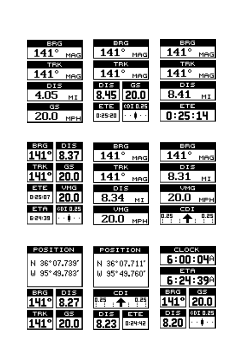
WINDOWS
The following is a listing of windows g roups A through O.
GROUP “A” GROUP “B” GROUP “C”
GROUP “D” GROUP “E” GROUP “F”
GROUP “G” GROUP “H” GROUP “I”
46
Page 51
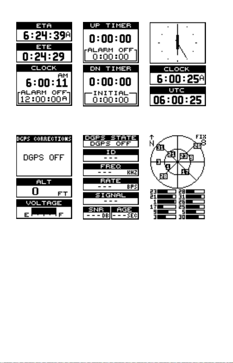
GROUP “J” GROUP “K” GROUP “L”
GROUP “M” GROUP “N” GROUP “O”
47
Page 52

DATUMS
WGS 84 .................
DEFAULT
ADINDAN...............
MEAN
ADINDAN...............
BURKINA
FASO
ADINDAN...............
CAMEROON
ADINDAN...............
ETHIOPIA
ADINDAN...............
MALI
ADINDAN...............
SENEGAL
ADINDAN...............
SUDAN
AFGOOYE .............
SOMALIA
AIN EL ABD ...........
1970
BAHRAIN
AIN EL ABD ...........
1970 SAUDI
ARABIA
ANNA 1 ASTRO ....
1965 COCOS
ISLANDS
ANTIGUA ...............
ISLAND
ASTRO 1943
ARC 1950 ..............
MEAN
ARC 1950 ..............
BOTSWANA
ARC 1950 ..............
BURUNDI
ARC 1950 ..............
LESOTHO
ARC 1950 ..............
MALAWI
ARC 1950 ..............
SWAZILAND
ARC 1950 ..............
ZAIRE
ARC 1950 ..............
ZAMBIA
ARC 1950 ..............
ZIMBABWE
WGS 1984
Default
Adindan
Mean for Ethiopia, Sudan
Adindan
Burkina Faso
Adindan
Cameroon
Adindan
Ethiopia
Adindan
Mali
Adindan
Senegal
Adindan
Sudan
Afgooye
Somalia
Ain el Abd 1970
Bahrain
Ain el Abd 1970
Saudi Arabia
Anna 1 Astro 1965
Cocos Islands
Antigua Island Astro 1943
Antigua (Leeward Islands)
Arc 1950
Mean for Botswana, Lesotho,
Malawi, Swaziland, Zaire, Zambia,
Zimbabwe
Arc 1950 - Botswana
Arc 1950 - Burundi
Arc 1950 - Lesotho
Arc 1950 - Malawi
Arc 1950 - Swaziland
Arc 1950 - Zaire
Arc 1950 - Zambia
Arc 1950 - Zimbabwe
ARC 1960 ..............
MEAN
ASCENSION..........
ISLAND
1958
ASTRO BEACON ..
E 1945
IWO JIMA
ASTRO DOS 714 ..
ST HELENA
ISLAND
ASTRO TERN ........
ISLAND
1961
ASTRONOMICAL ..
STATION ‘52
MARCUS ISLE
AUSTRALIAN ........
GEODETIC
1966
AUSTRALIAN ........
GEODETIC
1984
AYABELLE .............
LIGHTHOUSE
DJIBOUTI
BELLEVUE ............
(IGN) EFATE
ERRAOMANGO
BERMUDA .............
1957
BISSAU..................
GUINEA
BOGOTA ................
OBSERVATORY
COLOMBIA
BUKIT RIMPAH......
INDONESIA
CAMP AREA..........
ASTRO
ANT ARCTICA
CAMPO..................
INCHAUSPE
ARGENTINA
CANTON ASTRO ..
’66 PHOENIX
ISLANDS
CAPE .....................
SOUTH
AFRICA
CAPE .....................
CANAVERAL
BAHAMAS FL
48
Arc 1960 - Mean for Kenya,
Tanzania
Ascension Island 1958 Ascension Island
Astro Beacon E 1945 - Iwo Jima
Astro DOS 71/4 - St Helena Island
Astro Tern Island (FRIG) 1961 Tern Island
Astronomical Station 1952 Marcus Island
Australian Geodetic 1966 Australia & Tasmania
Australian Geodetic 1984 Australia & Tasmania
Ayabelle Lightlhouse - Djibouti
Bellevue (IGN) - Efate &
Erromango Islands
Bermuda 1957 - Bermuda
Bissau - Guinea-Bissau
Bogota Observatory - Colombia
Bukit Rimpah - Indonesia (Bangka
& Belitung Islands)
Camp Area Astro - Antarctica
(McMurdo Camp Area)
Campo Inchauspe - Argentina
Canton Astro 1966 - Phoenix
Islands
Cape - South Africa
Cape Canaveral - Bahamas,
Florida
Page 53

CARTHAGE ...........
TUNISIA
CH-1903 ................
CHATHAM .............
ISLAND ASTRO
NEW ZEALAND
CHUA ASTRO .......
P ARA GU AY
CORREGO ............
ALEGRE
BRAZIL
DABOLA ................
GUINEA
DJAKARTA .............
(BA TAVIA)
INDONESIA
DOS 1968 ..............
NEW GEORGIA
ISLANDS
EASTER ................
ISLAND
1967
EUROPEAN...........
1950 MEAN
WESTERN
EUROPEAN...........
1950 MEAN
CENTRAL
EUROPEAN...........
1950 MEAN
MIDDLE EAST
EUROPEAN...........
1950
CYPRUS
EUROPEAN...........
1950
EGYPT
EUROPEAN...........
1950 GREAT
BRIT AIN
EUROPEAN ‘50 .....
FINLAND
NORWA Y
EUROPEAN...........
1950
GREECE
EUROPEAN...........
1950
IRAN
Carthage - Tunisia
Switzerland
Chatham Island Astro 1971
New Zealand (Chatham Island)
Chua Astro
Paraguay
Corrego Alegre
Brazil
Dabola
Guinea
Djakarta (Batavia)
Indonesia (Sumatra)
DOS 1968
New Georgia Islands
(Gizo Island)
Easter Island 1967
Easter Island
European 1950
Mean for Austria, Belgium,
Denmark, Finland, France,
West Germany, Gibralter, Greece,
Italy, Luxembourg, Netherlands,
Norway, Portugal, Spain, Sweden,
Switzerland
European 1950
Mean for Austria, Denmark,
France, West Germany ,
Netherlands, Switzerland
European 1950
Mean for Iraq, Israel, Jordan,
Lebanon, Kuwait,
Saudi Arabia, Syria
European 1950
Cyprus
European 1950
Egypt
European 1950
England, Channel Islands, Ireland,
Scotland, Shetland Islands
European 1950
Finland, Norway
European 1950
Greece
European 1950
Iran
EUROPEAN...........
1950 ITALY
(SARDINIA)
EUROPEAN...........
1950 ITALY
(SICILY)
EUROPEAN...........
1950
MALTA
EUROPEAN...........
1950 SPAIN
PORTUGAL
EUROPEAN...........
1979
MEAN
FORT THOMAS.....
1955 NEVIS
ST. KITTS
GAN 1970 ..............
REPUBLIC OF
MALDIVES
GEODETIC ............
DATUM 1949
NEW ZEALAND
GRACIOSA ............
BASE SW
1948 AZORES
GUAM ....................
1963
GUNUNG ...............
SEGARA
INDONESIA
GUX 1 ASTRO.......
GUADALCANAL
ISLAND
HERAT NOR TH .....
AFGHANIST AN
HJORSEY ..............
1955
ICELAND
HONG KONG ........
1963
HU-TZU-SHAN ......
TAIWAN
INDIAN...................
BANGLADESH
INDIAN...................
INDIA NEPAL
INDIAN 1954 .........
THAILAND
VIETNAM
INDIAN 1975 .........
THAILAND
European 1950
Italy (Sardinia)
European 1950
(Sicily)
European 1950
Malta
European 1950
Portugal, Spain
European 1979
Mean for Austria, Finland,
Netherlands, Norway, Spain,
Sweden, Switzerland
Fort Thomas, 1955
Nevis, St. Kitts
(Leeward Islands)
Gan 1970
Republic of Maldives
Geodeic Datum 1949
New Zealand
Graciosa Base SW 1948
Azores (Faial, Graciosa, Pico,
Sao Jorge, Terceira)
Guam 1963
Guam
Gunung Segara
Indonesia (Kalimantan)
GUX 1 Astro
Guadalcanal Island
Herat North
Afghanistan
Hjorsey 1955
Iceland
Hong Kong 1963
Hong Kong
Hu-Tzu-Shan
Taiwan
Indian
Bangladesh
Indian
India, Nepal
Indian - 1954
Thailand, Vietnam
Indian - 1975
Thailand
49
Page 54

IRELAND ...............
1965
ISTS 061 ................
ASTRO 1968
S GEORGIA
ISTS 073 ................
ASTRO 1969
DIEGO GARCIA
JOHNSTON ...........
ISLAND
1961
KANDAWALA .........
SRI LANKA
KERGUELEN.........
ISLAND
1949
KERTAU 1948 ........
W MALAYSIA
SINGAPORE
KUSAIE ASTRO ....
CAROLINE 1951
ISLANDS
L C 5 ASTRO.........
1961 CA YMAN
BRAC ISLAND
LEIGON .................
GHANA
LIBERIA .................
1964
LUZON...................
PHILIPPINES
LUZON...................
PHILIPPINES
MINDANAO
MAHE ISLAND ......
1971
MASSAW A.............
ETHIOPIA
(ERITREA)
MERCHICH ...........
MOROCCO
MIDWAY ASTRO ...
1961
MINNA ...................
CAMEROON
MINNA ...................
NIGERIA
MONTSERRAT ......
ISLAND
ASTRO 1958
M’PORALOKO.......
GABON
Ireland 1965
Ireland
ISTS 061 Astro 1968
South Georgia Islands
ISTS 073 Astro 1969
Diego Garcia
Johnston Island 1961
Johnston Island
Kandawala
Sri Lanka
Kerguelen Island 1949
Kerguelen Island
Kertau 1948
West Malaysia & Singapore
Kusaie Astro 1951
Caroline Islands
L.C. 5 Astro 1961
Cayman Brac Island
Leigon
Ghana
Liberia 1964
Liberia
Luzon
Philipines
(Excluding Mindanao)
Luzon
Philipines (Mindanao)
Mahe 1971
Mahe Island
Massawa
Ethiopia (Eritrea)
Merchich
Morocco
Midway Astro 1961
Midway Islands
Minna
Cameroon
Minna
Nigeria
Montserrat Island Astro 1958
Montserrat
(Leeward Islands)
M’Poraloko
Gabon
NAHRWAN.............
OMAN
NAHRWAN.............
SAUDI ARABIA
NAHRWAN.............
UNITED ARAB
EMIRATES
NAPARIMA BWI.....
TRINIDAD AND
TOBAGO
N AMERICA ...........
1927 MEAN
CARRIBEAN
N AMERICA ...........
1927 MEAN
CENTRAL AMER
N AMERICA ...........
1927 MEAN
CANADA
N AMERICA ...........
1927 MEAN
CONUS
N AMERICA ...........
1927 MEAN
CONUS EAST
N AMERICA ...........
1927 MEAN
CONUS WEST
N AMERICA ...........
1927 ALASKA
N AMERICA ...........
1927 BAHAMAS
(NO SAN SALV)
N AMERICA ...........
1927 BAHAMAS
N AMERICAN ........
1927 CANADA
(WEST)
N AMERICAN ........
1927 CANADA
(CENTRAL)
N AMERICAN ........
1927 CANADA
EAST
N AMERICAN ........
1927 CANADA
NORTH
N AMERICAN ........
1927 CANADA
YUKON
50
Nahrwan
Oman (Masirah Island)
Nahrwan
Saudi Arabia
Nahrwan
United Arab Emirates
Naparima BWI
Trinidad & Tobago
North American 1927
Mean for Antigua, Barbados, Barbuda,
Caicos Islands, Cuba, Dominican
Republic, Grand Cayman, Jamaica,
Turks Islands
North American 1927
Mean for Belize, Costa Rica,
El Salvador, Guatmala, Honduras,
Nicaragua
North American 1927
Mean for Canada
North American 1927
Mean for CONUS
(Continental United States)
North American 1927
Mean for CONUS (East of Mississippi
River) including Louisiana, Missouri,
Minnesota
North American 1927
Mean for CONUS
(West of Mississippi River)
North American 1927
Alaska
North American 1927
Bahamas
(Except San Salvador Island)
North American 1927
Bahamas (San Salvador Island)
North American 1927
Canada (Alberta, British Columbia)
North American 1927
Canada (Manitoba, Ontario)
North American 1927
Canada (New Brunswick,
Newfoundland, Nova Scotia, Quebec)
North American 1927
Canada (Northwest Territories,
Saskatchewan)
North American 1927
Canada (Yukon)
Page 55

N AMERICAN ........
1927 CANAL
ZONE
N AMERICAN ........
1927 CUBA
N AMERICAN ........
1927
GREENLAND
N AMERICAN ........
1927 MEXICO
N AMERICAN ........
1983 ALASKA
CANADA CONUS
N AMERICAN ........
1983 CENTRAL
AM MEXICO
OBSERVATORIA ...
METEREO
1939 AZORES
OLD EGYPTIAN ....
1907 EGYPT
OLD HAWAIIAN.....
MEAN
OLD HAWAIIAN.....
HAWAII
OLD HAWAIIAN.....
KAUAI
OLD HAWAIIAN.....
MAUI
OLD HAWAIIAN.....
OAHU
OMAN ....................
ORD SURVEY .......
G BRITAIN
1936 MEAN
ORD SURVEY .......
G BRITAIN
1936 ENGLAND
ORD SURVEY G ...
BRITAIN 1936
ENGLND WALES
ORD SURVEY G ...
BRITAIN 1936
SCOTLAND
ORD SURVEY .......
G BRITAIN
1936 WALES
PICO DE ................
LAS NIEVES
CANARY ISLES
North American 1927
Canal Zone
North American 1927
Cuba
North American 1927
Greenland (Hayes Peninsula)
North American 1927
Mexico
North American 1983
Alaska, Canada, CONUS
North American 1983
Central America, Mexico
Observaorio Metereo 1939
Azores (Corvo & Flores Islands)
Old Egyptian 1907
Egypt
Old Hawaiian
Mean for Hawaii, Kauai,
Maui, Oahu
Old Hawaiian
Hawaii
Old Hawaiian
Kauai
Old Hawaiian
Maui
Old Hawaiian
Oahu
Oman
Oman
Ordinance Survey
Great Britain 1936 - Mean for
England, Isle of Man, Scotland,
Shetland Islands, Wales
Ordinance Survey
Great Britian 1936 - England
Ordinance Survey
Great Britian 1936 - England,
Isle of Man, Wales
Ordinance Survey
Great Britian 1936 - Scotland,
Shetland Islands
Ordinance Survey
Great Britian 1936 - Wales
Pico de las Nieves
Canary Islands
PITCAIRN ..............
ASTRO
1967
POINT 58 ...............
BURKINA
FASO NIGER
POINTE NOIRE .....
1948 CONGO
PORTO SANTO.....
1936 MADEIRA
ISLANDS
PROVISIONAL.......
S AMERICA
1956 MEAN
PROVISIONAL.......
S AMERICA
1956 BOLIVIA
PROVISIONAL.......
S AMERICA
1956 N CHILE
PROVISIONAL.......
S AMERICA
1956 S CHILE
PROV S AMER ......
1956
COLOMBIA
PROVISIONAL.......
S AMERICA
1956 ECUADOR
PROVISIONAL.......
S AMERICA
1956 GUYANA
PROVISIONAL.......
S AMERICA
1956 PERU
PROVI S AMER .....
1956
VENEZUELA
PROVISIONAL.......
S CHILEAN
1963 S CHLIE
PUERTO RICO ......
VIRGIN
ISLANDS
QA TAR ...................
NATIONAL
QORNOQ ..............
GREENLAND
(SOUTH)
REUNION ..............
MASCARENE
ISLANDS
ROME 1940 ...........
ITALY
(SARDINIA)
Pitcairn astro 1967
Pitcairn Island
Point 58
Mean for Burkina Faso & Niger
Pointe Noire 1948
Congo
Porto Santo 1936
Porto Santo, Madeira Islands
Provisional S. American 1956
Mean for Bolivia, Chile, Colombia,
Ecuador, Guyana, Peru, Venezuela
Provisional S. American 1956
Bolivia
Provisional S. American 1956
Chile (Northern, Near 19°S)
Provisional S. American 1956
Chile (Southern, Near 43°S)
Provisional S. American 1956
Colombia
Provisional S. American 1956
Ecuador
Provisional S. American 1956
Guyana
Provisional S. American 1956
Peru
Provisional S. American 1956
Venezuela
Provisional S. American 1956
Chile (South, Near 53°S) (Hito XVIII)
Puerto Rico
Puerto Rico, Virgin Islands
Qatar National
Qatar
Qornoq
Greenland (South)
Reunion
Mascarene Islands
Rome 1940
Italy (Sardinia)
51
Page 56

RT 90 .....................
SANTO (DOS) .......
’65 ESPIRITO
SANTO ISLAND
SAO BRAZ.............
AZORES
SAPPER HILL........
1943 EAST
FALKLND ISLE
SCHWARZECK .....
NAMIBIA
SEL VAGEM
GRANDE
SALVAGE ISLE
SOVIET..................
GEODETIC
SYSTEM 1985
S AMERICAN ........
1969 MEAN
S AMERICAN ........
1969
ARGENTINA
S AMERICAN ........
1969 BOLIVIA
S AMERICAN ........
1969 BRAZIL
S AMERICAN ........
1969 CHILE
S AMERICAN ........
1969
COLOMBIA
S AMERICAN ........
1969
ECUADOR
S AMERICAN ........
1969 ECUADOR
GALAP A GOS
S AMERICAN ........
1969 GUYANA
S AMERICAN ........
1969
P ARA GU AY
S AMERICAN ........
1969 PERU
S AMERICAN ........
1969 TOBAG O
AND TRINIDAD
S AMERICAN ........
1969
VENEZUELA
Sweden
Santo (DOS)
1965 Espirito Santo Island
Sao Braz
Azores (Sao Miguel,
Santa Maria Islands)
Sapper Hill 1943
East Falkland Island
Schwarzeck
Nambia
Selvagem Grande
Salvage Islands
SGS 85
Soviet Geodetic System 1985
South American 1969
Mean for Argentina, Bolivia,
Brazil, Chile, Colombia, Ecuador,
Guyana, Paraguay, Peru,
T rinidad & Tobago, Venezuela
South American 1969
Argentina
South American 1969
Bolivia
South American 1969
Brazil
South American 1969
Chile
South American 1969
Colombia
South American 1969
Ecuador
South American 1969
Ecuador (Baltra, Galapagos)
South American 1969
Guyana
South American 1969
Paraguay
South American 1969
Peru
South American 1969
Trinidad & Tobago
South American 1969
Venezuela
SOUTH ASIA .........
SINGAPORE .........
TANANARIVE ........
OBSERV ATORY
1925
MADAGASCAR
TIMBALAI ..............
1948 BRUNEI
E MALAYSIA
TOKYO...................
MEAN
TOKYO...................
JAPAN
TOKYO...................
KOREA
TOKYO...................
OKINAWA ..............
TRISTAN DA ..........
CUNHA
ASTRO 1968
VITI LEVU ..............
1916 FIJI
WAKE ....................
ENIWETOK ‘60 ......
MARSHALL ISL .....
WAKE ISLAND ......
ASTRO 1952
WGS 1972 .............
GLOBAL
DEFINITION
YACARE .................
URUGUAY
ZANDERIJ .............
SURINAME
South Asia
Singapore
Tananarive Observatory 1925
Madagascar
Timbalai 1948
Brunei, East Malaysia
(Sabah, Sarawak)
Tokyo
Mean for Japan, Korea, Okinawa
Tokyo
Japan
Tokyo
Korea
Tokyo
Okinawa
Tristan Astro 1968
Tristan da Cunha
Viti Levu 1916
Fiji (Viti Levu Island)
Wake
Eniwetok 1960
Marshall Islands
Wake Island Astro 1952
Wake Atoll
WGS 1972
Global Definition
Yacare
Uruguay
Zanderij
Suriname
52
Page 57

LOWRANCE ELECTRONICS
FULL ONE-YEAR WARRANTY
“We", “our”, or “us” refers to LOWRANCE ELECTRONICS, INC., the manufacturer of this
product. “You” or “your” refers to the first person who purchases this product as a consumer item for personal, family, or household use.
We warrant this product against def ects or malfunctions in materials and workmanship, and
against failure to conform to this product’ s written specifications, all for one year (1) from the
date of original purchase by you. WE MAKE NO O THER EXPRESS W ARRANTY OR REPRESENT ATION OF ANY KIND WHA TSOEVER CONCERNING THIS PRODUCT. Your remedies under this warranty will be available so long as y ou can show in a reasonable manner
that any defect or malfunction in materials or workmanship, or any non-conf ormity with the
product’s written specifications, occurred within one y ear from the date of your original purchase, which must be substantiated by a dated sales receipt or sales slip . Any such def ect,
malfunction, or non-conformity which occurs within one year from your original purchase date
will either be repaired without charge or be replaced with a new product identical or reasonably equivalent to this product, at our option, within a reasonable time after our receipt of the
product. If such def ect, malfunction, or non-conformity remains after a reasonable number of
attempts to repair by us, you ma y elect to obtain without charge a replacement of the product
or a refund for the product. THIS REPAIR, REPLACEMENT, OR REFUND (AS JUST DESCRIBED) IS THE EXCLUSIVE REMEDY AVAILABLE TO YOU AGAINST US FOR ANY
DEFECT, MALFUNCTION, OR NON-CONFORMITY CONCERNING THE PRODUCT OR
FOR ANY LOSS OR DAMAGE RESULTING FROM ANY OTHER CA USE WHATSOEVER.
WE WILL NOT UNDER ANY CIRCUMSTANCES BE LIABLE T O ANY ONE FOR ANY SPECIAL, CONSEQUENTIAL, INCIDENT AL, OR O THER INDIRECT D AMAGE OF ANY KIND .
Some states do not allow the exclusion or limitation of incidental or consequential damages,
so the above limitations or exclusions ma y not apply to you.
This warranty does NOT apply in the following circumstances: (1) when the product has
been serviced or repaired by anyone other than us, (2) when the product has been connected, installed, combined, altered, adjusted, or handled in a manner other than according to
the instructions furnished with the product, (3) when any serial number has been effaced,
altered, or removed, or (4) when any def ect, problem, loss, or damage has resulted from any
accident, misuse, negligence, or carelessness, or from any f ailure to provide reasonable and
necessary maintenance in accordance with the instructions of the owner’s manual for the
product.
We reserve the right to make changes or improvements in our products from time to time
without incurring the obligation to install such improvements or changes on equipment or
items previously manuf actured.
This warranty gives you specific legal rights and you ma y also hav e other rights which may
vary from state to state.
REMINDER: Y ou must retain the sales slip or sales receipt proving the date of your original
purchase in case warranty service is ever required.
LOWRANCE ELECTR ONICS, INC.
12000 E SKELLY DRIVE TULSA, OK 74128
(800) 324-1356
53
Page 58
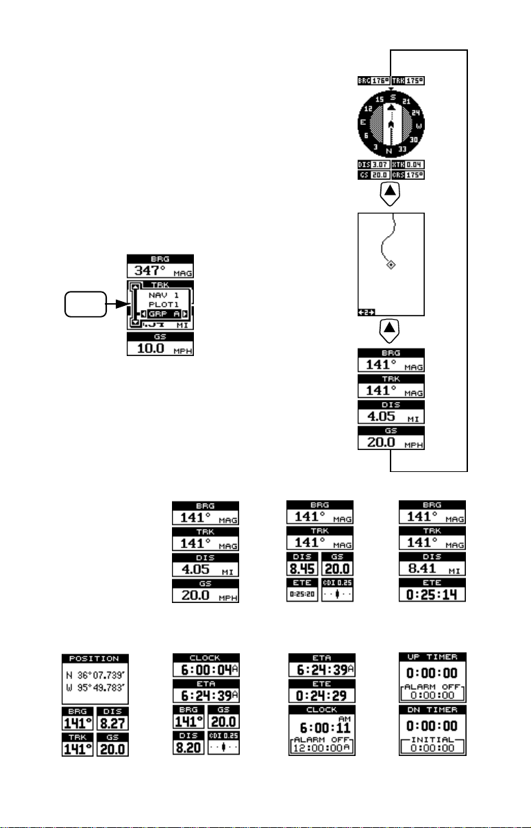
PAGES
Press the PAGES key to view the
pages menu, then using the up
and down arrow keys to switch
between nav, plot, and groups
screens. Use the right or left arrow keys to s witch between different screens on each page.
PAGES
GROUPS
SCREENS
GRP A GRP B GRP C
GRP H GRP I GRP J GRP K
54
Page 59

NAV
SCREENS
PLOT
SCREENS
NAV-1 NAV-2
GRP D
PLOT-1
GRP E GRP F GRP G
PLOT-2
GRP OGRP L GRP M GRP N
55
Page 60

How to Obtain Service
(Canadian Customers Only)
We back your investment in quality products with quick, expert service and genuine
Lowrance replacement parts. If you need service or repairs, contact the Lowrance
Factory Customer Service Department at the toll-free number listed below. A technician may be able to solve the prob lem and sav e you the incon venience of returning your
unit. You will be asked for your unit's serial number.
800-324-1356
Canada Only . Monday through F riday 8:00 A.M. - 8:00 P.M. Centr al Time.
When sending a product for repair, please do the f ollowing:
1. Alwa ys use the original shipping container and filler material the product was packed
in when shipping your product.
2 Always insure the parcel against damage or loss during shipment. Lowrance does
not assume responsibility for goods lost or damaged in transit.
3 . For proper testing, repair , and service, send a brief note with the product describing
the problem. Be sure to include y our name, return shipping address, and a daytime
telephone number.
How to Obtain Service
(International Customers Only - Except Canada)
If you need service or repairs, contact the dealer in the country you purchased your unit.
WARRANTY REPAIR WILL BE HONORED ONLY IN THE
COUNTRY UNIT WAS PURCHASED.
Please follow the shipping instructions shown below on this page if you ha ve to mail your
unit to the dealer. For proper testing, repair , and service, send a brief note with the product
describing the problem. Be sure to include your name, return shipping address, and a
daytime telephone number.
Accessory Ordering Information - All Countries
T o order accessories such as power cables or tr ansducers, please contact:
1. Your local dealer. Most quality dealers that handle GPS navigation equipment should
be able to assist you with these items. Consult your local telephone directory for
listings.
2. Canadian customers only can write:
Lowrance/Eagle Canada, 919 Matheson Blvd., E. Mississauga, Ontario L4W2R7
or fax 416-629-3118
59
Page 61

How to Obtain Service - U.S.A. Only
We back your investment in quality products with quick, expert ser vice
and genuine Lowrance® replacement parts. If you're in the United States
and you have questions, please contact the Factory Customer Service
Department using our toll-free number listed below. You must send the
unit to the factory for warranty service or repair. Please call the factory
before sending the unit. You will be asked for your unit's serial number.
Use the following toll-free number:
800-324-1356
Your unit is covered by a full one-year warranty. (See inside this manual
for complete warranty details .) If your unit fails and the failure is not co vered by the original warranty, Lowrance has a flat-rate repair policy that
covers your unit and accessories pac ked with the unit at the factory . There
is a 180-day warranty on all non-w arranty repairs from the f actory, which
is similar to the original warranty , b ut is for 180 days r ather than one year .
For further details, please call us at the above n umber.
Accessory Ordering Information
To order accessories such as power cables, please contact:
1) Your local marine dealer. Most quality dealers that handle marine electronic equipment should be able to assist you with these items. Consult
your local telephone directory for listings.
2) LEI Extras, Inc. P.O. Box 129 Catoosa, OK 74015-0129
or call
800-324-0045
(USA orders only.)
Lowrance Electronics may find it necessary to change or end our shipping policies, regulations, and special off ers at any time . We reserve the
right to do so without notice.
LITHO IN U.S.A. 12999 988-0145-36
60
 Loading...