

Page 1
1240A
IN-DASH MOUNT SONAR
INSTALLATION AND
OPERATION INSTRUCTIONS
http://www.lowrance.com
Page 2
INSTALLATION
MOUNTING
Your 1240A is designed for convenient mounting the dash of your boat, or
it can be mounted on any flat panel that's at least four inches in diameter.
If the sonar is to located in the vicinity of a magnetic compass, run it in
position temporarily to make certain it doesn't affect the compass readings.
If the compass heading changes, choose an alternate location. (Note: The
sonar must be running when you make this test.)
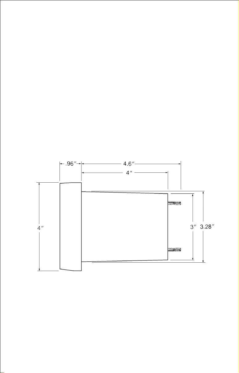
To mount the 1240A, first make certain there is clearance behind the dash
in the desired location. (See below for the unit's dimensions.) Also, be sure
there is enough room to connect power and attach the transducer connector at the rear of the unit. At least 5 1/4" are needed from the front surface
of the dash to clear all connectors and wiring. Once you've decided on the
mounting location, mark the spot.
Next, determine where to mount the control. Select an area with sufficient
space for the control decal on the front and enough depth behind the panel
for the control. The maximum panel thickness the control will attach to is
5/8". Make certain the control's cable will reach the display. Mark the spot
for the control.
Using a 3 3/8" hole saw, drill the display mounting hole. The display's bezel
will overlap the hole by 5/16", hiding minor chipping which may occur when
drilling the hole in fiberglass.
Page 3
Now drill the hole for the control. Use a 3/8" drill bit.
MAKE CERTAIN THAT ALL HOLES ARE DRILLED PERPENDICULAR
TO THE MOUNTING SURFACE AND NOT AT AN ANGLE.
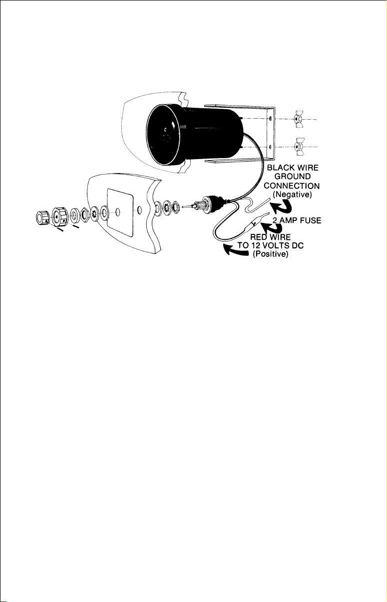
A "U" bracket is supplied to hold the sonar to the dash. Place it over the
studs on the back of the unit and secure it using the nylon wing nuts
provided. If the "U" bracket is too long, it can be cut to the desired length
with a saw.
Before mounting the control, clean the mounting surface for the control
decal. Remove the paper backing from the decal to expose the adhesive
and place it over the control's mounting location. Make certain the holes in
the decal and dash are aligned.
Mounting hardware for the control, consisting of two nuts, lockwashers,
and flat washers are supplied in the hardware pack. First, thread a nut onto
the shaft. The amount of threading depends on the thickness of the dash.
Place a lockwasher and a flat washer on the shaft. Insert the control in the
hole from the back side of the dash and place another flat washer and lock
washer onto the shaft. Thread the other nut on, but don't tighten it yet. Place
the large knob onto the shaft and tighten the set screw enough to lock it into
position on the flat side of the shaft. With the switch in the far left "OFF"
position, rotate the control so that the pointer on the knob aligns with the
"OFF" position on the decal. When it's properly positioned, slide the knob
off and tighten the nut on the control. About 1 1/2 threads should show
beyond the nut on the front of the dash. Place the foam washer and large
knob over the shaft and tighten the knob's setscrew. Place the small knob
onto the shaft, align the setscrew with the flat on the shaft, leave a small
gap between the small knob and the large one and tighten its setscrew.
Page 4

POWER CONNECTION
12-volt DC power for the 1240A is supplied from the boat's 12-volt electrical
system. You can connect the power either from an existing fuse block that's
behind the dash or directly to the battery. An in-line fuse holder is supplied
with the unit in case a fuse is not available. Attach the fuse holder as close
to the power source as possible. This will help protect both the unit and the
power cable in the event of a short circuit.
Caution! Never connect this unit to power without a fuse!
The positive wire is red. The negative wire is black and should be attached
to the negative ground buss or the negative side of the battery.
This unit is protected from accidental polarity reversal and no damage will
result if the battery connections are wrong. However, the unit will not work
until correct polarity is applied.
OPERATION
To turn the sonar on, rotate the large control knob from the "off" position
to either 40 feet or 100 feet. This is a three-position switch and controls both
power on/off and range select. To turn the sonar off, rotate the switch back
to the "off" position.
SENSITIVITY CONTROL
(Pull Out for Maximum
Suppression)
RANGE AND POWER
ON/OFF
RANGE SELECT
There are two scales on the 1240A - 0 to 40 feet and 0 to 100 feet. Make
the selection by turning the large knob to the 40 or 100 setting. Depths
greater than 100 feet can also be measured. For instance, as the water
depth goes from 90 to 110 feet, you will see the bottom signal on the dial
move past the "zero" signal to the 10-foot mark. Thus, on the second
revolution, depths of 100 to 200 feet can be read by adding 100 feet to the
reading on the dial.
Page 5

If you're in doubt about the depth, turn the unit off until the scan disc stops.
Turn it back on and watch to see if the bottom signal completes one
revolution before stopping. If it does, the present water depth is the depth
shown plus 100 feet. If the signal travels around the dial two times, the
water depth is the depth shown plus 200 feet.
SENSITIVITY
Vary the sensitivity by rotating the small knob. It works similarly to the
volume control on a radio. Turned fully counterclockwise, it's at minimum
and the only signal that will appear on the dial, (unless it's in extremely
shallow water) will be the constant surface signal at "0". Turning the knob
clockwise will increase the receiver sensitivity and weaker echoes from
deeper water shows on the dial.
For example, if you are in 10 feet of water and the sensitivity control is at
minimum, you will see only the "0" signal. As you turn up the sensitivity, a
Page 6

signal appears at 10 feet on the dial. As it's turned up more, this signal will
get wider and other smaller signals from fish (if present) appear between
0 and 10 feet. The bottom signal gets wider because you are seeing more
bottom area. Remember that the true depth is always the shallowest edge
of the bottom signal, NOT the middle. As you turn the sensitivity up more,
another signal appears at 20 feet on the dial, double the depth of the first
signal. It's caused by the sound waves hitting bottom, bouncing back,
hitting the surface of the water and then bouncing down to the bottom and
back again. These signals have travelled double the actual depth.
Always set the sensitivity to return a steady bottom signal, regardless of
depth. To show fish, adjust the sensitivity to show a second bottom signal,
when possible.
SUPPRESSION
Use suppression to reduce or eliminate false flashes on the dial caused by
electrical interference or cavitation on the transducer. With the small knob
pushed in, suppression is at minimum. This is the normal position for
trolling as it gives the highest resolution (ability of the sonar to separate
targets such as fish that are close together or near the bottom). To switch
to high suppression, pull out the small knob. You will feel a "click". The knob
in the "pulled-out" position gives the best interference rejection which is
usually required when operating at speed. Because of the type of suppression circuity used by Lowrance, the unit's sensitivity is not affected.
(Sensitivity in a sonar unit is measured by the instrument's ability to read
at depth plus show details.) A small amount of resolution will be lost when
engaging suppression. Note that suppression can be engaged by pulling
out on the sensitivity knob at any time.
SPECIFICATIONS
Dimensions.............................. Fits 3 3/8" diameter mounting hole
Maximum outside diameter 4"
Depth behind mounting surface 4 5/8"
Weight: .................................... 23 oz (with control)
Dial .......................................... 0-40 feet; 0-100 feet
Input Voltage ........................... 12 vDC (10.5 to 15 vDC)
Current Drain........................... 200 ma., one echo
Transmitter Frequency ............ 192 kHz
Pulse Repetition Rate.............. 0-60 ft - 60 pps
0-100 ft - 24 pps
Pulse Width ............................. Suppression minimum - 200 us
Suppression maximum - 800 us
Output Power .......................... 150 watts peak to peak (19 watts RMS)
Page 7

LOWRANCE ELECTRONICS
FULL ONE-YEAR WARRANTY
“We", “our”, or “us” refers to LOWRANCE ELECTRONICS, INC., the manufacturer of this
product. “You” or “your” refers to the first person who purchases this product as a consumer item for personal, family, or household use.
We warrant this product against defects or malfunctions in materials and workmanship,
and against failure to conform to this product’s written specifications, all for one year (1)
from the date of original purchase by you. WE MAKE NO OTHER EXPRESS WARRANTY
OR REPRESENTATION OF ANY KIND WHATSOEVER CONCERNING THIS PRODUCT.
Your remedies under this warranty will be available so long as you can show in a reasonable manner that any defect or malfunction in materials or workmanship, or any nonconformity with the product’s written specifications, occurred within one year from the date
of your original purchase, which must be substantiated by a dated sales receipt or sales
slip. Any such defect, malfunction, or non-conformity which occurs within one year from
your original purchase date will either be repaired without charge or be replaced with a
new product identical or reasonably equivalent to this product, at our option, within a reasonable time after our receipt of the product. If such def ect, malfunction, or non-conf ormity
remains after a reasonable number of attempts to repair by us, you may elect to obtain
without charge a replacement of the product or a refund for the product. THIS REPAIR,
REPLACEMENT, OR REFUND (AS JUST DESCRIBED) IS THE EXCLUSIVE REMEDY
AVAILABLE TO YOU AGAINST US FOR ANY DEFECT, MALFUNCTION, OR NON-CONFORMITY CONCERNING THE PRODUCT OR FOR ANY LOSS OR DAMAGE RESULTING FROM ANY OTHER CAUSE WHATSOEVER. WE WILL NOT UNDER ANY CIRCUMSTANCES BE LIABLE TO ANYONE FOR ANY SPECIAL, CONSEQUENTIAL, INCIDENTAL, OR OTHER INDIRECT DAMAGE OF ANY KIND.
Some states do not allow the exclusion or limitation of incidental or consequential damages, so the above limitations or exclusions may not apply to you.
This warranty does NOT apply in the following circumstances: (1) when the product has
been serviced or repaired by anyone other than us, (2) when the product has been connected, installed, combined, altered, adjusted, or handled in a manner other than according to the instructions furnished with the product, (3) when any serial number has been
effaced, altered, or removed, or (4) when any defect, problem, loss, or damage has resulted from any accident, misuse, negligence, or carelessness, or from any failure to provide reasonable and necessary maintenance in accordance with the instructions of the
owner’s manual for the product.
We reserve the right to make changes or improvements in our products from time to time
without incurring the obligation to install such improvements or changes on equipment or
items previously manufactured.
This warranty gives you specific legal rights and you ma y also hav e other rights which may
vary from state to state.
REMINDER: You must retain the sales slip or sales receipt proving the date of your original purchase in case warranty service is ever required.
This warranty does not apply to any database or its contents supplied initially with this
product. For warranty information on the databases and their contents, please refer to the
“Databases Limited Warranty” included with this product.
LOWRANCE ELECTRONICS, INC. 12000 E SKELLY DR TULSA, OK 74128
Page 8

How to Obtain Service - U.S.A. Only
We back your investment in quality products with quick, expert ser vice
and genuine Lowrance® replacement parts. If you're in the United States
and you have questions, please contact the Factory Customer Service
Department using our toll-free number listed below. You must send the
unit to the factory for warranty service or repair. Please call the factory
before sending the unit. You will be asked for your unit's serial number.
Use the following toll-free number:
800-324-1356
U.S.A.only. Monday through Fr iday 8:00 A.M. - 8:00 P.M. Central time, except holidays.
Your unit is covered by a full one-year warranty. (See inside this manual
for complete warranty details .) If y our unit fails and the failure is not covered by the original warranty, Lowrance has a flat-rate repair policy that
covers your unit and accessories pac ked with the unit at the factory . There
is a 180-day warranty on all non-w arranty repairs from the f actory, which
is similar to the original warranty , but is f or 180 days r ather than one year .
For further details, please call us at the above n umber.
http://www.lowrance.com
Accessory Ordering Information
To order accessories, please contact:
1) Your local marine dealer. Most quality dealers that handle marine electronic equipment should be able to assist you with these items. Consult
your local telephone directory for listings.
2) LEI Extras, Inc. P.O. Box 129 Catoosa, OK 74015-0129
or call
800-324-0045
(USA orders only.)
On the internet, http://www.leiextr as.com
Lowrance Electronics may find it necessary to change or end our shipping policies, regulations, and special offers at any time. We reserve the right to do so without notice.
Copyright 2000, Lowrance Electronics, Inc.
LITHO IN U.S.A. 988-0061-02 Rev A.
 Loading...