

Page 1
I & M Mark 708ME
3170 Wasson Road • Cincinnati, OH 45209 USA
Phone 513-533-5600 • Fax 513-871-0105
[email protected] • www.lowfl owvalve.com
Installation & Maintenance Instructions for
Mark 708 & Motor Actuator
Warning: Jordan LowFlow Control Valves must only be used, installed and repaired in accordance with these
Installation & Maintenance Instructions. Observe all applicable public and company codes and regulations. In
the event of leakage or other malfunction, call a qualifi ed service person; continued operation may cause system
failure or a general hazard. Before servicing any valve, disconnect, shut off, or bypass all pressurized fl uid. Before
disassembling a valve, be sure to release all spring tension.
Please read these instructions carefully!
5. For best control, 3’ 0” straight sections of pipe
should be installed on either side of the valve.
Your Jordan LowFlow Valve product will provide you with
long, trouble-free service if it is correctly installed and
maintained. Spending a few minutes now reading these
instructions can save hours of trouble and downtime
later. When making repairs, use only genuine Jordan
LowFlow Valve parts, available for immediate shipment
from the factory.
6. In preparing threaded pipe connections, care
should be exercised to prevent pipe-sealing compound from getting into pipelines. Pipe sealing
compound should be used sparingly, leaving the
two end threads clean. Jordan uses, and recommends, thread sealer Tefl on ribbon.
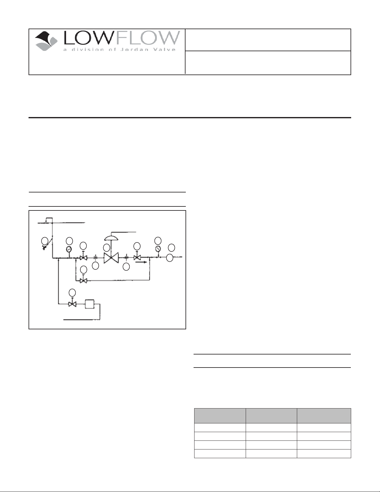
7. The fl ow arrow on the valve body must be pointed
in the direction of the fl ow. Ideally the valve should
Ideal Installation
be installed in the highest horizontal line of piping to provide drainage for inlet and outlet piping,
to prevent water hammer, and to obtain faster response.
8. If possible, install a relief valve downstream from
the valve. Set at 15 psi above the control point of
3
4
1
7
5
2
1
2
4
6
R
the valve.
9. In hot vapor lines, upstream and downstream piping near the valve should be insulated to minimize
condensation.
10. Evaluate inlet and outlet pipe friction losses and velocities to decide when smaller outlet piping might
1. Shut off Valve
1
2. Pipe Union
3. Strainer and Drain Valve
4. Pressure Gauge
5. Mark 708ME
6. Relief Valve
7. Bypass Valve
1. To control very low fl ow rates, Mark 708 control
valves are often provided with trims having very
small clearances. To keep this trim functioning
cause excessive back pressure. When required, a
standard tapered expander connected to the outlet
of the valve is recommended.
11. Where surges are severe, a piping accumulator is
recommended.
12. On steam control applications, install a steam trap
with suffi cient capacity to drain the coil or condenser. Be sure to have a good fall to the trap, and no
backpressure. Best control is maintained if the coil
or condenser is kept dry.
properly, it is essential that the fl uid fl owing through
the valve be clean.
Start-Up Procedure
2. To protect the valve from grit, scale, thread chips
and other foreign matter, ALL pipelines and piping
components should be blown out and thoroughly
cleaned before the installation process begins.
3. Shutoff valves, pressure gauges, and by-pass piping
1. Be sure that the action of the control valve and of
the controller are such that you achieve the desired
results. The action can be changed if needed using the instructions shown in “Reversing Action”.
should be installed as indicated in the Installation
Schematic to provide easier adjustment, operation
and testing.
4. A line strainer should be installed on the inlet side
of the valve to protect it from grit, scale, and other
foreign matter. A 0.033 perforated screen is usually
suitable for this purpose. Line strainers are available from Jordan Valve.
Increase in pressure
or temperature must:
Close Valve Air to Close (direct) Direct
Close Valve Air to Open (reverse) Reverse
Open Valve Air to Close (direct) Reverse
Open Valve Air to Open (reverse) Direct
And the action of
the valve is:
Then the action of the
controller must be:
-1-
Page 2
2. The control valve has been pre-set by Jordan Valve,
however, fi ner adjustment may be required to compensate for the system conditions of your application.
3. With inlet, outlet and bypass shutoff valves closed,
and no pressure in the down stream line, fully
open the outlet valve. Slowly open the inlet valve
just enough to start fl ow through the control valve.
Increase the fl ow gradually by slowly opening the
inlet shutoff valve. Do not fully open the inlet valve
until you are sure that the controller and control
valve have control of the system. Usually, the
handwheel on the inlet valve will turn freely when
this point is reached.
4. To shut off the line fl uid, close the inlet shutoff
valve fi rst, and then close the outlet shutoff valve.
may be dressed with a very fi ne crocus cloth, but
generally it is best not to as the stem has a fi ne machined fi nish. Use approved non-residue-forming
solvent for cleaning. Wipe dry with clean cloth.
3. Insert a new set of packing in packing box. Press
each ring down in place with a tube as it is installed.
4. After packing is installed, assemble packing adapter, gland, and gland nuts. Tighten the nuts hand
tight.
5. The fi nal packing adjustment should be made with
the valve pressurized and the packing tightened
just enough to stop any leakage, while stroking the
valve. Excessive tightening could cause the stem
to stick and result in improper valve operation
due to high friction forces.
Maintenance
Caution: Make certain that there is no pressure in the
valve before loosening any fi ttings or joints. The following steps are recommended:
1. Close the inlet shutoff valve.
2. Allow pressure to bleed off through the downstream piping. Do not attempt to reverse the fl ow
through the valve by bleeding pressure from the
upstream side of the valve.
3. When the pressure gauges indicate that all pressure has been removed from the system, close the
outlet shutoff valve, and the valve may be serviced.
Note: refer to the drawing at the end of this document for description and proper orientation of parts.
To reduce maintenance time, refer to proper fi gure and
follow steps indicated below for applicable maintenance
operation.
Proposed Maintenance
Procedure
Renewing Stem Packing Packing Replacement
Valve Disassembly,
Inspecting Parts, Replacing
Plug or Seat Ring
Valve Reassembly Valve Reassembly
Motor Valve Seat Spring
Preload
Packing Replacement
Renew valve plug stem packing if control valve has been
in service beyond normal maintenance, and packing
shows signs of wear. Wear will be indicated by leakage,
which cannot be corrected by minor tightening of the
packing fl ange. An additional packing ring can be installed to overcome minor leakage without dismantling
the control valve or breaking valve plug connection.
1. Remove the actuator from the bonnet. (See Removing Actuator from Valve.)
2. Remove all of the packing and discard. Clean valve
stem and packing box thoroughly. The valve stem
Follow Steps...
Valve Disassembly
Motor Valve Seat Spring
Preload
Removing Actuator from Valve
1. Position the valve to full open and disconnect all
electrical connections.
2. Remove the actuator from the valve as follows:
loosen the two stem connector nuts and move
them down the stem. Lock these nuts together.
Remove the two nuts that secure the packing
fl ange, then the then the two hex bolts that secure
the yoke to the bonnet. Remove the gland nuts (11)
that secure the packing gland (9) and the packing
adaptor (7). Using a wrench on the nuts and on
the fl ats of the actuator stem, turn the stem connector (while holding the actuator stem in place)
until the stems disengage. The actuator will be free
of the valve.
Body & Bonnet Disassembly
1. For actuator removal, refer to section on “Removing
Actuator”.
2. Remove the body/bonnet bolts and carefully sepa-
rate the body from the bonnet so as not to damage
delicate trim components.
3. Remove stem nuts and indicator. Withdraw the
stem and plug out of the bonnet. (The smaller trims
have a one-piece stem and plug, which can be
withdrawn through the packing.)
4. With a socket wrench, remove the seat from the
body. Remove and discard the body/bonnet gasket.
5. Soft seats are disassembled by removing the seat
cap from the seat and then the soft seat can be
removed.
6. Clean all parts with an approved non-residue-forming solvent. Remove encrusted material with a very
fi ne Crocus or aluminum oxide cloth. However, do
not use these abrasives on the seating surface or
the trim surface (the portion of the plug that enters
the seat bore.) The machining tolerances on these
surfaces are so closely controlled that you might
change the valves fl ow characteristic.
7. Inspect all parts and replace and worn or damaged
parts. It is always advisable to replace seals and
-2-
Page 3
gaskets. DO NOT attempt to resurface seating surfaces of the plug or seat. Seats and plugs are only
sold in factory-matched sets.
Valve Reassembly
1. Soft seated valves: insert soft seat into the seat
cavity, install the seat cap and tighten.
2. Lubricate the seat threads with a lubricant such as
NO-LOK and thread the seat into the body. Torque
to values shown.
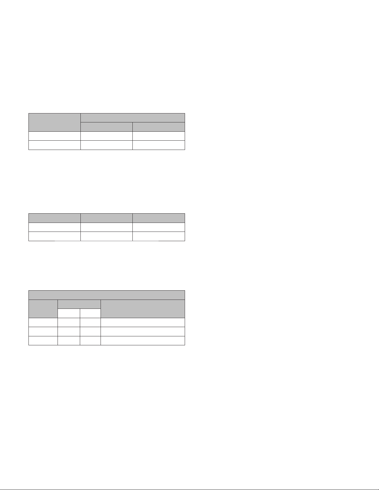
Valve Size
3/4” 26 310
1/2” 20 240
ft. - lbs. in. - lbs.
Seat Torque
3. Guided trim: Assemble plug to stem.
4. Insert the stem into the bonnet. Set the gasket
around the boss on the bonnet. Carefully assemble
the bonnet to the body and allow the plug to center
into the seat. Push down on the stem to be sure
that the plug has fully engaged the seat. Handtighten the body bolts.
ed down the stem and then locked together.
3. Slowly stroke the motor to closed position, while
rotating valve stem and stem nuts back and forth
(approximately ¼ turn). Caution: valve stem should
rotate freely. When it no longer rotates freely, the
plug is in contact with the seat, and the motor must
be stopped or damage may occur. If required, the
valve stem may be threaded into the actuator stem
to allow motor to complete stroke.
4. With motor in full closed position and stopped by
limit switch, rotate the stem down until the plug is
in contact with the seat, and turn and additional ¼
- ½ turn to preload the seat.
5. Position motor to open position, and confi rm that
the motor is stopped by the limit switch prior to
the plug reaching the upper stop. Without rotating
the stem, thread the stem nuts up and lock them
against the actuator stem.
Note: limit switches and high/low set points are
factory-set. If command signal range will not fully
stroke the valve, refer to electrical connection diagram for the motor actuator that was shipped with
the valve. With seat spring preload set, if plug hits
upper stop prior to limit switch, the limit switch will
require adjustment; consult factory for procedure.
Valve Size Gasket Material Quantity Required
All Tefl on 1
1/2” & 3/4” Grafoil 2
5. Remove and replace the packing as described in
“Packing Replacement”.
6. While holding the plug fi rmly in position in the
seat, secure the body to the bonnet with the bolts.
Torque bolts evenly to the values shown.
Torque Values (in. - lbs.)
Material
Gr. BD* 125 200 650 deg. (also SAE GR. 8)
Gr. B7 125 200 1000 deg. F
Gr. B6 125 200 900 deg. F (410 SST)
* Standard Bolting
Bolt Diameter
5/16” 3/8”
Limitation
7. Reassemble the two stem nuts and indicator all
the way onto the stem threads. Lock the two nuts
together.
8. Position to full open.
9. Mount the motor actuator support legs to the bonnet fl ange and secure with the hex nuts. Thread
the stem into the motor actuator stem. Hold the
actuator stem with a wrench to prevent it from turning.
Motor Valve Seat Spring Preload
1. Position the valve to be full open.
2. The two stem nuts should be loosened and thread-
-3-
Page 4
Trim Removal Instructions
Ordering Spare Parts
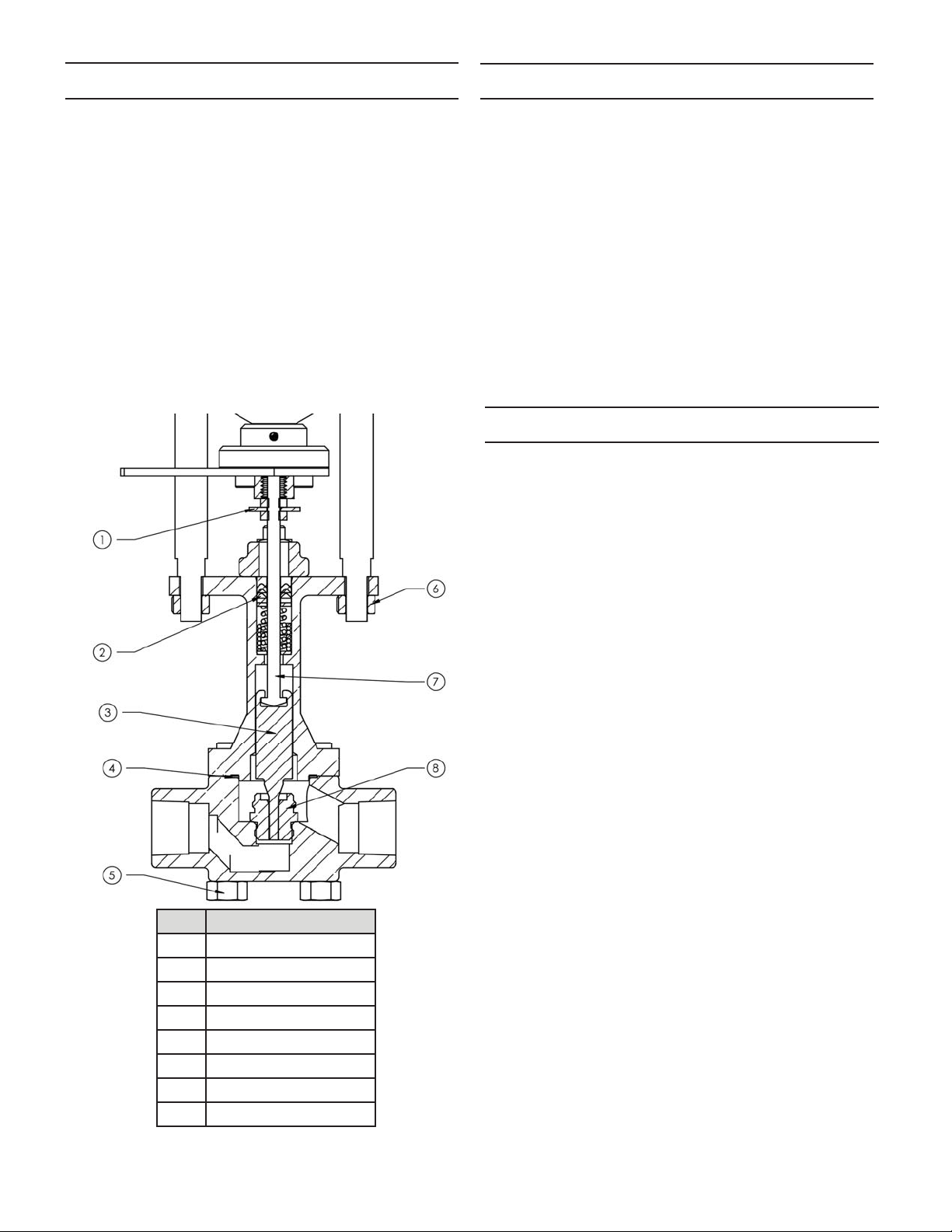
Referring to drawing below:
1. Position valve stem at mid-stroke.
2. Unthread the four bolts (5) and remove body.
3. Loosen hex nuts and indicator washer (1). Unthread
stem from motor shaft and remove nuts and washer
(1).
4. Remove the hex nuts (6) and lift motor from valve.
5. Push stem (7) through body. (DO NOT push stem
threads through packing unless stem is being replaced).
6. Slide plug (3) off stem.
7. Remove and install new seat (8) – optional.
8. Install new gasket (4). Install new packing (2) if stem
is removed.
9. Assemble in reverse order. Note: stem must be
threaded into connector until bottomed out to
maintain stroke adjustment.
Use only genuine Jordan Valve parts to keep your valve
in good working order. So that we can supply the parts,
which were designed for your valve, we must know exactly which product you are using. The only guarantee to
getting the correct replacement parts is to provide your
Jordan Representative with the valve serial number. This
number is located on the valve identifi cation tag. If the
serial number is not available, the parts needed for your
valve might be determined using the following information: Model Number, Valve Body Size, Seat Material and
Cv Rating, Spring Range and Set Point, Trim Material, Part
Name - Number and Quantity.
NOTE: Any parts ordered without a valve serial number
that are found to be incorrect are subject to up to a minimum 25% restock charge when returned.
Trouble Shooting
If You Experience Erratic Control:
Oversizing can cause cycling or hunting (recalcu-
late the size required).
Undersizing can cause the control point to drop off
under peak loads (increase the trim size).
Inlet pressure to the valve maybe varying signifi -
cantly and the controller may not be following it
(adjust the controller).
Control loop may require equal percentage trim if
high rangabilities are being utilized.
Steam traps may need reconditioning.
Safety relief valves may be leaking.
Valve stroke may be out of adjustment or there may
be foreign matter in the valve preventing full movement.
Item Description
1 Lock Nuts/ Indicator
2 Packing
3 Plug
4 Gasket
5 Bolts
6 Hex Nuts
7Stem
8 Seat
If You Experience Insuffi cient Flow:
Check shutoff valves to be sure they are fully open.
Inlet pressure to valve may be insuffi cient to pro-
vide the needed fl ow (check the inlet pressure with
a pressure gauge).
Strainers should be checked for clogging and
blown down if needed.
Steam traps may need reconditioning.
Dirt in the trim may prevent the valve from passing
its full capacity.
Diaphragm failure or insuffi cient air pressure to re-
verse acting (air-to-open) actuators would prevent
the valve from properly stroking open. Incorrect actuator spring adjustment in reverse acting actuators
would prevent the valve properly stroking open.
If You Experience Overpressure (outlet):
Dirt in the trim may prevent valve from shutting off.
Diaphragm failure, incorrect actuator spring adjust-
ment, or insuffi cient air pressure to direct acting
(air-to-close) actuators would prevent the valve
from properly stroking closed.
-4-
Page 5
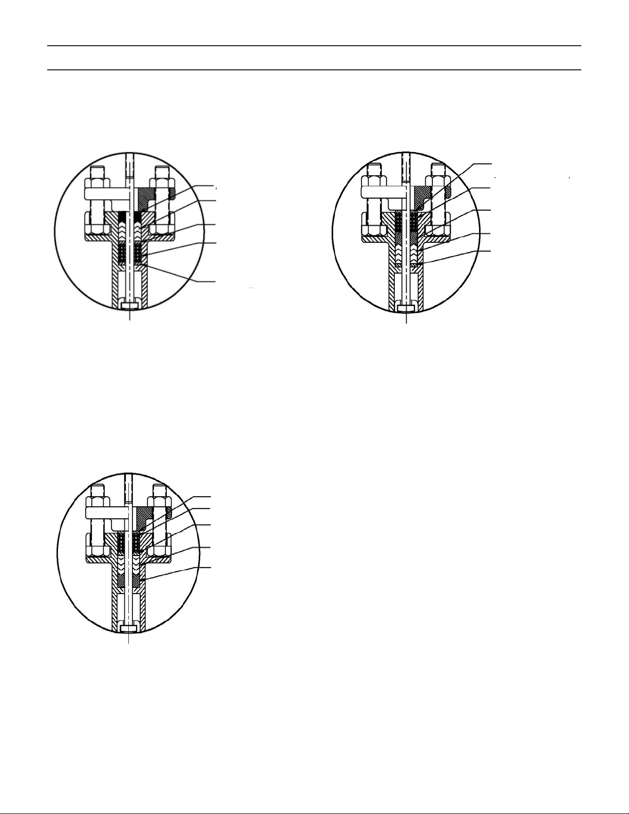
Mark 708ME Packing Assembly
Adaptor
Packing
Packing Washer
Spring (2)
Packing Washer
Packing Washer
(exotic material)
Spring (2)
Adaptor
Packing
Packing Washer
(exotic material)
Standard Packing
Inverted Packing - for Exotic Body Material
(Put spring on top of packing.)
(JV P/N 92065)
Packing Washer
Spring (2)
Packing Washer
Packing (Inverted)
Adaptor
Packing for Vacuum
(Invert packing rings and put spring on top)
(JV P/N 96071)
-5-
Page 6
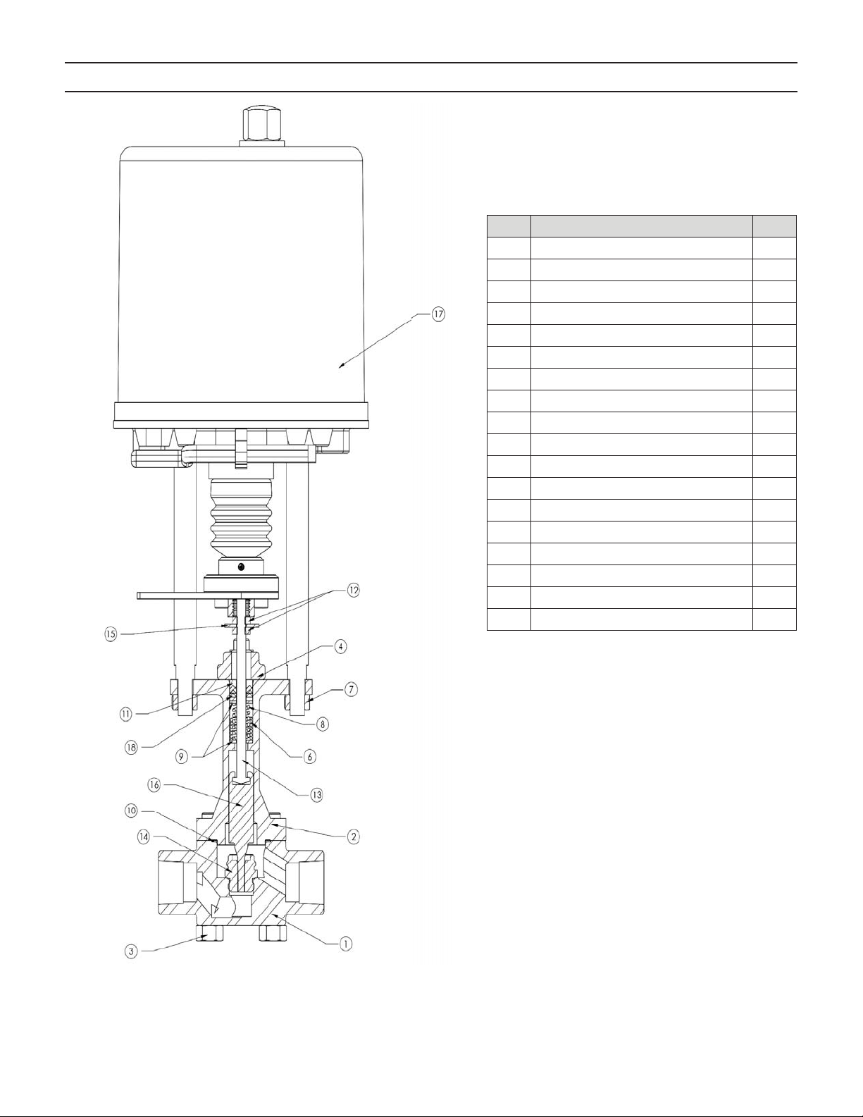
Illustration and Parts List
Item Description Qty.
1 Body 1
2 Bonnet 1
3 HHCS 5/16- 18 x 2” 4
4 Gland 1
5 HHCS 5/16-18 x 1”(Not Shown) 2
6 Packing Spring 1
7 Hex Nut 5/16-18 2
8 Spring 1
9 Retainer Washer 2
10 Body Gasket 1
11 Adapter 1
12 Hex Nut 10-24 2
13 Stem 1
14 Seat 1
15 Washer 1
16 Plug 1
17 Motor 1
18 Packing 1
-6-
Page 7
-7-
Page 8
-8-
Page 9
-9-
Page 10
-10 -
Page 11
-11-
Page 12
-12-
Page 13
-13-
Page 14
-14-
Page 15
-15-
Page 16
Bulletin IM-MK708ME-1114
3170 Wasson Road • Cincinnati, OH 45209 USA
Phone 513-533-5600 • Fax 513-871-0105
[email protected] • www.lowfl owvalve.com
-16 -
 Loading...